JP6963243B2 - Wire stop clip - Google Patents

Wire stop clip Download PDF

Info

Publication number
JP6963243B2
JP6963243B2 JP2021035186A JP2021035186A JP6963243B2 JP 6963243 B2 JP6963243 B2 JP 6963243B2 JP 2021035186 A JP2021035186 A JP 2021035186A JP 2021035186 A JP2021035186 A JP 2021035186A JP 6963243 B2 JP6963243 B2 JP 6963243B2
Authority
JP
Japan
Prior art keywords
electric wire
portions
movable
wire
receiving portion
Prior art date
Legal status (The legal status is an assumption and is not a legal conclusion. Google has not performed a legal analysis and makes no representation as to the accuracy of the status listed.)
Active
Application number
JP2021035186A
Other languages
Japanese (ja)
Other versions
JP2021141806A (en
Inventor
将 田中
仁司 柿本
勝也 安河内
Original Assignee
九州電力送配電株式会社
九州電気産業株式会社
Priority date (The priority date is an assumption and is not a legal conclusion. Google has not performed a legal analysis and makes no representation as to the accuracy of the date listed.)
Filing date
Publication date
Application filed by 九州電力送配電株式会社, 九州電気産業株式会社 filed Critical 九州電力送配電株式会社
Publication of JP2021141806A publication Critical patent/JP2021141806A/en
Application granted granted Critical
Publication of JP6963243B2 publication Critical patent/JP6963243B2/en
Active legal-status Critical Current
Anticipated expiration legal-status Critical

Links

Images

Landscapes

  • Clamps And Clips (AREA)
  • Insulated Conductors (AREA)
  • Electric Cable Installation (AREA)
  • Suspension Of Electric Lines Or Cables (AREA)

Description

本発明は、電柱の腕金に碍子を介して高圧架空電線等の電線を挟持する電線止めクリップに関するものである。 The present invention relates to an electric wire stopper clip for sandwiching an electric wire such as a high-voltage overhead electric wire through an insulator on a utility pole arm.

従来、この種の電線止めクリップは、電柱の腕金の碍子の上部に、金属製支持台を固定し、金属製支持台の上に金属製の電線止めクリップを固定し、当該クリップにて電線を挟持固定していた。 Conventionally, in this type of electric wire stopper clip, a metal support base is fixed on the upper part of the insulator of the arm of the utility pole, and a metal wire stopper clip is fixed on the metal support base, and the electric wire is used by the clip. Was pinched and fixed.

上記電線止めクリップの構造は、長方形支持枠の一方に金属製の電線受部を設け、ボルトに螺合しボルトの回転により、上記電線受部に近接し得る金属製の可動電線受部を設け、上記電線受部と上記可動電線受部により電線を挟持していた(特許文献1)。 In the structure of the wire stop clip, a metal wire receiving portion is provided on one side of the rectangular support frame, and a metal movable wire receiving portion that can be brought close to the wire receiving portion by screwing into the bolt and rotating the bolt is provided. , The electric wire was sandwiched between the electric wire receiving portion and the movable electric wire receiving portion (Patent Document 1).

また、上記電線受部と上記可動電線受部の内側に各々針電極を設け、上記電線を挟持したとき上記両針電極を、電線の両側から被覆を破って導体に接触させることで、電力用バリスタを通じて地中に流れる接地回路を構成し、高圧架空電線を落雷等による雷サージから保護する構成であった。 Further, needle electrodes are provided inside the electric wire receiving portion and the movable electric wire receiving portion, respectively, and when the electric wire is sandwiched, both needle electrodes are brought into contact with the conductor by breaking the coating from both sides of the electric wire. A grounding circuit that flows into the ground through a varistor was constructed to protect the high-voltage overhead power line from lightning surges caused by lightning strikes.

このような従来の電線止めクリップは、上記電線受部の針電極の両側に、電線の外周に沿う一対の半円弧状の押え円弧板(金属製)が設けられており、上記可動電線受部の針電極の両側にも、同じく電線の外周に沿う一対の半円弧状の押え円弧板(金属製)が設けられており、上記電線を挟持した状態において、上記電線の両側から上記押え円弧板(電線受部側2か所、可動電線受部側2か所の計4か所)が電線を挟持する構成であった(特許文献1)。 In such a conventional electric wire stop clip, a pair of semi-arc-shaped pressing arc plates (made of metal) along the outer periphery of the electric wire are provided on both sides of the needle electrode of the electric wire receiving portion, and the movable electric wire receiving portion is provided. A pair of semi-arc-shaped presser arc plates (made of metal) are also provided on both sides of the needle electrode of the wire, and the presser arc plates (made of metal) are provided from both sides of the wire while the wire is sandwiched. (Two places on the electric wire receiving part side and two places on the movable electric wire receiving part side, a total of four places) were configured to sandwich the electric wire (Patent Document 1).

また、同様のクリップとして、碍子上の金具の中央部に被覆を剥いだ電線をボルトにて固定し、その両側の電線に沿う左右方向の一定範囲を、電線の上下部を覆う硬質の金属製カバーにて被覆する構成のものが提案されている(特許文献2)。 Also, as a similar clip, the stripped wire is fixed to the center of the metal fitting on the insulator with bolts, and a certain range in the left-right direction along the wire on both sides is made of hard metal that covers the upper and lower parts of the wire. A structure that is covered with a cover has been proposed (Patent Document 2).

実開平6−7120号公報Jikkenhei 6-7120 特開2008−181819号公報Japanese Unexamined Patent Publication No. 2008-181819

ところで、上記特許文献1の装置では、押え円弧板が硬質の金属製であるため、電線が風等で煽られると、上記電線が長さ方向に対して直交する方向に振動し、上記振動による電線の曲げ応力が、上記電線と上記押え円弧板との接触部に集中するという課題があった。 By the way, in the apparatus of Patent Document 1, since the pressing arc plate is made of hard metal, when the electric wire is fanned by wind or the like, the electric wire vibrates in a direction orthogonal to the length direction, and the vibration causes the electric wire. There is a problem that the bending stress of the electric wire is concentrated on the contact portion between the electric wire and the pressing arc plate.

また、上記特許文献2の装置では、電線の風圧による振動に対しては、硬質金属による押え金具先端に電線の曲げ応力が集中し、電線の経年劣化を早めるおそれがあった。 Further, in the device of Patent Document 2, the bending stress of the electric wire is concentrated on the tip of the holding metal fitting made of hard metal in response to the vibration caused by the wind pressure of the electric wire, which may accelerate the aged deterioration of the electric wire.

本発明は上記従来の課題に鑑みてなされたものであり、弾性を有する線状部材により電線を把持し得るように構成することにより、電線が振動しても、電線の特定部位への応力の集中を抑止し得る電線止めクリップを提供することを目的とする。 The present invention has been made in view of the above-mentioned conventional problems, and by configuring the electric wire so that it can be gripped by an elastic linear member, even if the electric wire vibrates, the stress on a specific portion of the electric wire is applied. It is an object of the present invention to provide a wire stop clip that can suppress concentration.

上記の目的を達成するため本発明は、
第1に、金属製矩形枠を基台とし、一端部が上方に延長されることで電線受部が形成され、上記電線受部の左右側板に溝が各々形成され、上記電線受部には、上記電線受部の左右に水平方向に延びる、1本が上下に往復する上線部と下線部と、上記上線部と上記下線部の各先端部側の折り返し部分を有する形状の弾性線材からなる左右一対の電線把持部が、その各上記折り返し部分を外向きに両上記溝に係合された状態で各基端部を以って左右水平に各々固定され、上記基台の上記電線受部と対向面に金属製のボルトが貫装されるとともに、上記ボルトに螺合状態にて金属製の可動電線受部が設けられ、上記可動電線受部の左右側板に溝が各々形成され、上記可動電線受部には、上記可動電線受部の左右に水平方向に延びる、1本が上下に往復する上線部と下線部と、上記上線部と上記下線部の各先端部側の折り返し部分を有する形状の弾性線材からなる左右一対の可動電線把持部が、その各上記折り返し部分を外向きに両上記溝に係合された状態で各基端部を以って左右水平に各々固定され、左右の上記電線把持部に沿って電線を配置した状態にて、上記ボルトを回転させて上記可動電線受部を上記電線受部に近接させることにより、左右一対の上記電線把持部と左右一対の上記可動電線把持部により、上記電線における上記電線受部と上記可動電線受部の左右の上記電線前後の両側面が所定長に亘り挟持された挟持状態となるものである電線止めクリップにより構成される。
In order to achieve the above object, the present invention
First, using a metal rectangular frame as a base, one end is extended upward to form an electric wire receiving portion, and grooves are formed on the left and right side plates of the electric wire receiving portion, respectively, and the electric wire receiving portion has a groove. It is composed of an elastic wire having a shape extending horizontally to the left and right of the electric wire receiving portion and having an upper line portion and an underline portion in which one reciprocates up and down, and a folded portion on each tip side of the upper line portion and the underline portion. The pair of left and right electric wire grips are fixed horizontally to the left and right by each base end portion in a state where the folded portions thereof are outwardly engaged with both the grooves, and the electric wire receiving portion of the base is used. A metal bolt is pierced on the facing surface, and a metal movable electric wire receiving portion is provided in the bolt in a screwed state, and grooves are formed on the left and right side plates of the movable electric wire receiving portion. The movable electric wire receiving portion includes an overlined portion and an underlined portion extending horizontally to the left and right of the movable electric wire receiving portion, and a folded portion on each tip side of the overlined portion and the underlined portion. A pair of left and right movable electric wire gripping portions made of elastic wire having a shape are fixed horizontally to the left and right by each base end portion in a state where the folded portions thereof are outwardly engaged with the grooves. at the left and right in a state of placing the electrodeposition line along the electrical wire gripping unit, the movable wire receiving portion by rotating the bolt by proximity to the wire receiving portion, right and left and right pair of the electrical wire gripping unit by the movable electrical wire gripping unit, the wire clipped in which both sides of the front and rear of the left and right of the electric wires of the wire receiving portion and said movable wire receiving portion of the electric wire is clamped state of being sandwiched for a predetermined length It is composed.

金属製矩形枠は、例えば金属製長方形枠(9)により構成することができる。尚、金属製矩形枠は長方形に限らず、正方形等も含まれる。1本が上下に往復する部分は例えば上線部(20b)、下線部(20c)により構成することができる。折り返し部分は例えばU字状部(20a)又は菱形部(20g)により構成することができる。上記電線把持部及び可動電線把持部の基端部は、電線把持部及び可動電線把持部の溝係合部(21,21)及び挿通部(22,22)とすることができる。このように構成すると、電線止クリップの両側の電線の、前面側側面と後面側側面とを弾性線材からなる電線把持部及び可動電線把持部にて所定長に亘り挟持することができ、電線が前後方向に振動しても上記電線把持部と可動電線把持部は、電線の振動に合わせて弾性変形することができ、電線の挟持部の特定部位に応力が集中することがなく、電線の破断、破損を抑止することができる。 The metal rectangular frame can be configured by, for example, the metal rectangular frame (9). The metal rectangular frame is not limited to a rectangle, but also includes a square and the like. The portion where one reciprocates up and down can be composed of, for example, an overlined portion (20b) and an underlined portion (20c). The folded portion can be composed of, for example, a U-shaped portion (20a) or a diamond-shaped portion (20g). The base end portion of the electric wire grip portion and the movable electric wire grip portion can be a groove engaging portion (21, 21) and an insertion portion (22, 22) of the electric wire grip portion and the movable electric wire grip portion. With this configuration, the front side surface and the rear side side surface of the electric wires on both sides of the electric wire stop clip can be sandwiched by the electric wire gripping portion and the movable electric wire gripping portion made of the elastic wire for a predetermined length, and the electric wire can be held. Even if it vibrates in the front-rear direction, the electric wire gripping portion and the movable electric wire gripping portion can be elastically deformed according to the vibration of the electric wire, and the stress does not concentrate on a specific part of the electric wire holding portion, and the electric wire breaks. , Damage can be suppressed.

第2に、上記電線把持部及び上記可動電線把持部の上記折り返し部分はU字状部であることを特徴とする上記第1記載の電線止めクリップにより構成される。 Secondly, the electric wire grip portion and the folded portion of the movable electric wire grip portion are formed by the electric wire stopper clip according to the first aspect, which is a U-shaped portion.

折り返し部分をU字状部とすることにより、電線把持部の簡単な形状にて、電線の挟持部の特定部位への応力集中を防止すると共に、電線の破断、破損を抑止することができる。 By forming the folded portion into a U-shaped portion, the simple shape of the electric wire gripping portion can prevent stress concentration in a specific portion of the electric wire holding portion and prevent breakage or breakage of the electric wire.

第3に、上記電線把持部及び可動電線把持部の上記U字状部の先端は、上記電線から離れる方向に傾斜した反部が形成されている上記第2記載の電線止めクリップにより構成される。 Thirdly, the tip of the U-shaped portion of the electric wire grip portion and the movable electric wire grip portion is formed by the electric wire stopper clip according to the second description, wherein a counter portion inclined in a direction away from the electric wire is formed. ..

U字状部に反部を設けることにより、電線把持部の上下に往復する部分(上下線部)が電線の側面に密着し、これにより電線を確実に挟持することができる。 By providing the reverse portion in the U-shaped portion, the portion reciprocating up and down (upper and lower wire portion) of the electric wire grip portion is brought into close contact with the side surface of the electric wire, whereby the electric wire can be reliably sandwiched.

第4に、上記電線把持部及び上記可動電線把持部の上記折り返し部分は菱形部であることを特徴とする上記第1記載の電線止めクリップにより構成される。 Fourth, the electric wire gripping portion and the folded portion of the movable electric wire gripping portion are formed by the electric wire stopper clip according to the first aspect, which is a rhombic portion.

折り返し部を菱形部とすることにより、菱形部の先端屈曲部に電線の軸方向の中心を合わせることができ、より確実に電線を挟持することができる。 By forming the folded portion into a rhombus portion, the center of the electric wire in the axial direction can be aligned with the bent portion at the tip of the rhombus portion, and the electric wire can be more reliably sandwiched.

第5に、上記電線把持部及び上記可動電線把持部の上記菱形部は一対の屈曲部と一つの先端屈曲部を具備しており、上記一対の屈曲部は上記電線の方向に突出して形成されることにより、上記電線把持部の上記屈曲部と上記可動電線把持部の上記屈曲部により電線を包み込むように構成されたものである上記第4記載の電線止めクリップにより構成される。 Fifth, the rhombic portion of the electric wire grip portion and the movable electric wire grip portion includes a pair of bent portions and one tip bent portion, and the pair of bent portions are formed so as to project in the direction of the electric wire. As a result, it is configured by the electric wire stopper clip according to the fourth item, which is configured to wrap the electric wire by the bent portion of the electric wire grip portion and the bent portion of the movable electric wire grip portion.

このように構成すると、電線の軸方向の中心を先端屈曲部に合わせることができると共に、一対の屈曲部により電線を包み込むことができるので、電線を挟持していく過程において、電線が電線把持部から外れることを防止して、確実に電線を挟持することができる。 With this configuration, the center of the electric wire in the axial direction can be aligned with the bent tip portion, and the electric wire can be wrapped by the pair of bent portions. Therefore, in the process of sandwiching the electric wire, the electric wire grips the electric wire. It is possible to prevent the electric wire from coming off and to securely pinch the electric wire.

第6に、上記電線把持部及び上記可動電線把持部の上記折り返し部分は、上記上線部の上記先端部と上記下線部の上記先端部の間隔を拡幅すると同時に、上記上線部の上記先端部及び上記下線部の上記先端部から電線方向に折り曲げられた折曲部が各々形成され、かつ両上記折曲部の先端部間を上下方向に結ぶ連結部が形成され、上記連結部は上記電線の円周方向に沿う湾曲状に形成され、これにより上記折り返し部は全体に三角形状の三角部として形成されているものである上記第1記載の電線止めクリップにより構成される。 Sixth, the folded portion of the electric wire grip portion and the movable electric wire grip portion widens the distance between the tip portion of the overlined portion and the tip portion of the underlined portion, and at the same time, the tip portion of the overlined portion and the tip portion of the overlined portion. Bent portions bent in the direction of the electric wire are formed from the tip portion of the underlined portion, and a connecting portion connecting the tips of both the bent portions in the vertical direction is formed. The folded portion is formed in a curved shape along the circumferential direction, whereby the folded portion is formed as a triangular portion having a triangular shape as a whole.

このように構成すると、三角部の湾曲状の連結部を電線の円周方向に沿わせることができ、三角部にて電線の前方側側面と後方側側面を包み込むことができるため、電線を確実に挟持することができるし、弾性線材からなる電線把持部及び可動電線把持部にて所定長に亘り電線を挟持することができるので、電線の挟持部の特定部位に応力が集中することがなく、電線の破断、破損を抑止することができる。 With this configuration, the curved connecting portion of the triangular portion can be aligned along the circumferential direction of the electric wire, and the front side surface and the rear side side surface of the electric wire can be wrapped by the triangular portion, so that the electric wire can be secured. Since the electric wire can be sandwiched between the electric wire gripping portion and the movable electric wire gripping portion made of elastic wire for a predetermined length, stress does not concentrate on a specific part of the electric wire sandwiching portion. , It is possible to prevent breakage and breakage of electric wires.

第7に、左側の上記電線把持部と右側の上記電線把持部は、各一対の上記上下線部を上下方向に位置させた状態で水平方向の同一水準に位置しており、左側の上記可動電線把持部と右側の上記可動電線把持部は、各一対の上記上下線部を上下方向に位置させた状態で水平方向に同一水準に位置しており、上記電線受部の左右の上記電線把持部と上記可動電線受部の左右の上記可動電線把持部は、各々同一水準位置に設けられているものである上記第1〜6の何れかに記載の電線止めクリップにより構成される。 Seventh, the electric wire grip portion on the left side and the electric wire grip portion on the right side are located at the same level in the horizontal direction with each pair of the upper and lower wire portions positioned in the vertical direction, and the movable portion on the left side. The electric wire gripping portion and the movable electric wire gripping portion on the right side are located at the same level in the horizontal direction with each pair of the upper and lower wire portions positioned in the vertical direction, and the electric wire gripping portions on the left and right of the electric wire receiving portion. The movable wire gripping portions on the left and right of the portion and the movable wire receiving portion are configured by the electric wire stopper clip according to any one of 1 to 6 above, which are provided at the same level position.

このように構成すると、電線止クリップの左右両側の電線において、電線の左右の円弧状の各前方側側面と左右の各後方側側面を、各々左右一対の上下線部にて挟持することができ、電線止クリップの左右両側の電線を安定して挟持することができると共に、挟持部における特定部位に応力が集中するのを抑止することができる。 With this configuration, in the electric wires on the left and right sides of the electric wire stop clip, each of the left and right arcuate front side surfaces and the left and right rear side surfaces of the electric wire can be sandwiched by a pair of left and right vertical line portions. , The electric wires on both the left and right sides of the electric wire stop clip can be stably sandwiched, and the concentration of stress on a specific portion of the sandwiched portion can be suppressed.

第8に、上記電線受部には上記左右側板間に第1針電極を導通状態で固定すると共に、上記可動電線受部には上記左右側板間に第2針電極を導通状態で固定し、上記電線の上記挟持状態において、両上記第1及び第2針電極が上記電線の被覆を突き破って導体に接触する構成である上記第1〜7の何れかに記載の電線止めクリップにより構成される。 Eighth, the first needle electrode is fixed to the electric wire receiving portion between the left and right side plates in a conductive state, and the second needle electrode is fixed to the movable electric wire receiving portion between the left and right side plates in a conductive state. The wire stopper clip according to any one of 1 to 7 above, wherein both the first and second needle electrodes break through the coating of the wire and come into contact with the conductor in the sandwiched state of the wire. ..

上記第1針電極は針電極(15)とすることができ、上記第2針電極は針電極(27)とすることができる。このように構成すると、電線を把持することにより、同時に、針電極を電線の導体に導通させることができ、落雷時等の放電ルートを容易に構成することができる。また上記針電極の左右の電線の所定長に亘り電線把持部及び可動電線把持部にて電線を把持し得るので、針電極近傍での電線の応力集中を防止し得て、電線止クリップの放電機能が害されることがない。 The first needle electrode can be a needle electrode (15), and the second needle electrode can be a needle electrode (27). With this configuration, by gripping the electric wire, the needle electrode can be electrically conducted to the conductor of the electric wire at the same time, and a discharge route at the time of a lightning strike or the like can be easily configured. Further, since the electric wire can be gripped by the electric wire gripping portion and the movable electric wire gripping portion over the predetermined lengths of the electric wires on the left and right of the needle electrode, it is possible to prevent the stress concentration of the electric wire in the vicinity of the needle electrode and discharge the electric wire stop clip. The function is not impaired.

第9に、左右の上記電線把持部は後方向の附勢力を上記電線に与えるべく、上記各基端部から各上記折り返し部分が上記可動電線受部方向に各々傾斜しており、左右の上記可動電線把持部は前方向の附勢力を上記電線に与えるべく、上記各基端部から各上記折り返し部分が上記電線受部方向に各々傾斜しているものである上記第1〜8の何れかに記載の電線止めクリップにより構成される。 9. The movable electric wire grip portion is any one of the above 1 to 8 in which each of the folded portions is inclined in the direction of the electric wire receiving portion from each of the base end portions in order to apply an urging force in the forward direction to the electric wire. Consists of the wire stopper clip described in.

このように構成すると、左右の電線把持部と左右の可動電線把持部により電線を挟持した状態において、電線の前方側側面と後方側側面には、左右の電線把持部の弾性線材による後方向きの附勢力と、左右の可動戦線把持部の弾性線材による前方向きの附勢力が常時作用していることになり、電線止クリップの左右両側において電線を確実に挟持することができ、これにより電線把持部と可動電線把持部が電線に密着して電線の振動に追従し得るため、電線への曲げ応力を均等に分散することができる。 With this configuration, when the wires are sandwiched between the left and right wire grips and the left and right movable wire grips, the front and rear sides of the wires are facing backward by the elastic wires of the left and right wire grips. The urging force and the forward urging force due to the elastic wire of the left and right movable front grips are always acting, and the wire can be securely pinched on both the left and right sides of the wire stop clip, thereby gripping the wire. Since the portion and the movable electric wire grip portion are in close contact with the electric wire and can follow the vibration of the electric wire, the bending stress on the electric wire can be evenly distributed.

第10に、上記金属製矩形枠の左右側面板から外側水平方向に、一対の水平載置板が設けられ、左右の上記電線把持部に沿って配置された上記電線は、上記一対の水平載置板上に載置されるように構成され、上記電線受部側の上記第1針電極は後方側に向かう末広がり状のテーパ部が設けられ、上記可動電線受部側の上記第2針電極は前方側に向かう末広がり状のテーパ部が設けられ、上記水平載置板上に載置された上記電線を上記第1針電極の上記テーパ部と上記第2針電極の上記テーパ部が掬い上げ、上記電線のセンタリングが行われるものである上記第8に記載の電線止めクリップにより構成される。 Tenth, a pair of horizontal mounting plates are provided in the lateral horizontal direction from the left and right side plates of the metal rectangular frame, and the electric wires arranged along the left and right electric wire grip portions are the pair of horizontal mounting plates. The first needle electrode on the wire receiving portion side is provided with a divergent tapered portion toward the rear side so as to be mounted on the mounting plate, and the second needle electrode on the movable wire receiving portion side. Is provided with a divergent tapered portion toward the front side, and the tapered portion of the first needle electrode and the tapered portion of the second needle electrode scoop up the electric wire mounted on the horizontal mounting plate. It is composed of the electric wire stopper clip according to the eighth item, wherein the electric wire is centered.

第1針電極の後方側に向かう末広がり状のテーパ部とはテーパ部(15d,15d’)をいう。第2針電極の前方側に向かう末広がり状のテーパ部とはテーパ部(27c,27c’)をいう。このように構成すると、水平載置部に電線を載置した場合は、可動電線把持部を電線把持部に近接させる際、電線を第1及び第2針電極で掬い上げ、センタリングすることができる。また、電線受部及び可動電線受部より電線が左右方向に出た位置において、当該電線が上下方向等に移動した際、電線把持部及び可動電線把持部がその弾性により電線に沿って上下方向に移動することができ、電線受部及び可動電線受部から左右方向に出た位置の電線が上下方向に移動した場合においても、電線把持部及び可動電線把持部が電線の動きに沿って移動可能であるため、より効果的に電線を把持することができるし、応力の集中を効果的に防止することができる。 The divergent tapered portion toward the rear side of the first needle electrode means the tapered portion (15d, 15d'). The divergent tapered portion toward the front side of the second needle electrode means the tapered portion (27c, 27c'). With this configuration, when the electric wire is placed on the horizontal mounting portion, the electric wire can be scooped up and centered by the first and second needle electrodes when the movable electric wire grip portion is brought close to the electric wire grip portion. .. Further, when the electric wire moves in the vertical direction or the like at a position where the electric wire protrudes from the electric wire receiving portion and the movable electric wire receiving portion in the left-right direction, the electric wire grip portion and the movable electric wire grip portion move in the vertical direction along the electric wire due to its elasticity. Even when the electric wire at the position protruding from the electric wire receiving part and the movable electric wire receiving part in the left-right direction moves in the vertical direction, the electric wire gripping part and the movable electric wire gripping part move along with the movement of the electric wire. Since it is possible, the electric wire can be gripped more effectively, and the concentration of stress can be effectively prevented.

第11に、上記金属製矩形枠は、電柱の腕金に設けられた碍子上に固定された金属製支持台の上面に固定されたものである上記第1〜10の何れかに記載の電線止めクリップにより構成される。 Eleventh, the electric wire according to any one of the above 1 to 10, wherein the metal rectangular frame is fixed to the upper surface of a metal support base fixed on an insulator provided on the arm of a utility pole. It consists of a stop clip.

上記金属製支持台は例えば上金具(5)により構成することができる。このように構成すると、本発明の電線止クリップを複数の電柱に設けて、当該電線止クリップにて電線を保持することで、風の振動等によっても電線の破損又は破断を極力抑止することができる。 The metal support base can be configured by, for example, the upper metal fitting (5). With this configuration, the wire stop clips of the present invention are provided on a plurality of utility poles, and the wires are held by the wire stop clips, so that damage or breakage of the wires can be suppressed as much as possible due to wind vibration or the like. can.

第12に、上記電線の上記挟持状態において、上記金属製矩形枠と地面は電力用バリスタを介して接地されているものである上記第11記載の電線止めクリップにより構成される Twelvely, in the pinched state of the electric wire, the metal rectangular frame and the ground are grounded via a power varistor.

このように構成すると、高圧架空電線を落雷等の雷サージ等から保護することができる。 With this configuration, the high-voltage overhead power line can be protected from lightning surges such as lightning strikes.

本発明は上述のように、電線止クリップの両側の電線の、前面側側面と後面側側面とを弾性線材からなる電線把持部及び可動電線把持部にて所定長に亘り挟持することができ、電線が前後方向等に振動しても上記電線把持部と可動電線把持部は、電線の振動に合わせて弾性変形することができ、電線の挟持部の特定部位に応力が集中することがなく、電線の破断、破損を抑止することができる。 As described above, in the present invention, the front side surface and the rear side side surface of the electric wires on both sides of the electric wire stop clip can be sandwiched by the electric wire gripping portion and the movable electric wire gripping portion made of the elastic wire for a predetermined length. Even if the electric wire vibrates in the front-rear direction or the like, the electric wire grip portion and the movable electric wire grip portion can be elastically deformed according to the vibration of the electric wire, and stress does not concentrate on a specific part of the electric wire holding portion. It is possible to prevent breakage and breakage of electric wires.

また、折り返し部分をU字状部とすることにより、電線把持部の簡単な形状にて、電線の挟持部の特定部位への応力集中を防止すると共に、電線の破断、破損を抑止することができる。 In addition, by forming the folded portion into a U-shaped portion, the simple shape of the electric wire gripping portion can prevent stress concentration in a specific part of the electric wire holding portion and prevent breakage or breakage of the electric wire. can.

また、U字状部に反部を設けることにより、電線把持部の上下に往復する部分(上下線部)が電線の側面に密着し、これにより電線を確実に挟持することができる。 Further, by providing the reverse portion in the U-shaped portion, the portion reciprocating up and down (upper and lower wire portion) of the electric wire grip portion is brought into close contact with the side surface of the electric wire, whereby the electric wire can be reliably sandwiched.

また、菱形部の先端屈曲部に電線の軸方向の中心を合わせることができ、より確実に電線を挟持することができる。 Further, the center of the electric wire in the axial direction can be aligned with the bent tip of the rhombus portion, and the electric wire can be more reliably sandwiched.

また、折り返し部を菱形部とすることにより、電線の軸方向の中心を先端屈曲部に合わると共に、一対の屈曲部により電線を包み込むことができるので、電線を挟持していく過程において、電線が電線把持部から外れることを防止して、確実に電線を挟持することができる。 Further, by forming the folded portion into a diamond-shaped portion, the center of the electric wire in the axial direction can be aligned with the bent end portion, and the electric wire can be wrapped by the pair of bent portions. Can be prevented from coming off from the wire gripping portion, and the wire can be securely pinched.

また、三角部の湾曲状の連結部を電線の円周方向に沿わせることができ、三角部にて電線の前方側側面と後方側側面を包み込むことができるため、電線を確実に挟持することができるし、弾性線材からなる電線把持部及び可動電線把持部にて所定長に亘り電線を挟持することができるので、電線の挟持部の特定部位に応力が集中することがなく、電線の破断、破損を抑止することができる。 In addition, the curved connecting portion of the triangular portion can be aligned along the circumferential direction of the electric wire, and the front side surface and the rear side side surface of the electric wire can be wrapped by the triangular portion, so that the electric wire can be securely sandwiched. In addition, since the electric wire can be sandwiched over a predetermined length by the electric wire gripping portion and the movable electric wire gripping portion made of elastic wire, stress does not concentrate on a specific part of the electric wire sandwiching portion, and the electric wire is broken. , Damage can be suppressed.

また、電線止クリップの左右両側の電線において、電線の左右の円弧状の各前方側側面と左右の各後方側側面を、各々左右一対の上下線部にて挟持することができ、電線止めクリップの左右両側の電線を安定して挟持することができると共に、挟持部における特定部位に応力が集中するのを抑止することができる。 Further, in the electric wires on both the left and right sides of the electric wire stop clip, each of the left and right arcuate front side surfaces and the left and right rear side surfaces of the electric wire can be sandwiched by a pair of left and right upper and lower wire portions. It is possible to stably pinch the electric wires on both the left and right sides of the above, and it is possible to prevent stress from concentrating on a specific portion of the pinching portion.

また、電線把持部及び可動電線把持部にて電線を把持することにより、同時に、針電極を電線の導体に導通させることができ、落雷時等の接地ルートを容易に構成することができる。また上記針電極の左右の電線の所定長に亘り電線把持部及び可動電線把持部にて電線を把持し得るので、針電極近傍での電線の応力集中を防止し得て、電線止クリップの放電機能が害されることがない。 Further, by gripping the electric wire with the electric wire gripping portion and the movable electric wire gripping portion, the needle electrode can be electrically conducted to the conductor of the electric wire at the same time, and the grounding route at the time of a lightning strike can be easily configured. Further, since the electric wire can be gripped by the electric wire gripping portion and the movable electric wire gripping portion over the predetermined lengths of the electric wires on the left and right of the needle electrode, it is possible to prevent the stress concentration of the electric wire in the vicinity of the needle electrode and discharge the electric wire stop clip. The function is not impaired.

また、左右の電線把持部と左右の可動電線把持部により電線を挟持した状態において、電線の前方側側面と後方側側面には、左右の電線把持部の弾性線材による後方向きの附勢力と、左右の可動戦線把持部の弾性線材による前方向きの附勢力が常時作用していることになり、電線止クリップの左右両側において両電線把持部が電線に密着し、電線に対する曲げ応力を分散すると共に、電線を確実に保持することができる。 Further, in a state where the electric wire is sandwiched between the left and right electric wire gripping portions and the left and right movable electric wire gripping portions, the front side surface and the rear side side surface of the electric wire are provided with a rearward urging force by the elastic wires of the left and right electric wire gripping portions. The forward urging force of the elastic wire of the left and right movable front grips is always acting, and both wire grips are in close contact with the wire on both the left and right sides of the wire stop clip, and the bending stress on the wire is dispersed. , The electric wire can be held securely.

また、水平載置部に電線を載置した場合は、可動電線把持部を電線把持部に近接させる際、電線を第1及び第2針電極で掬い上げ、センタリングすることができる。また、電線受部及び可動電線受部より電線が左右方向に出た位置において、当該電線が上下方向等に移動した際、電線把持部及び可動電線把持部がその弾性により電線に沿って上下方向に移動することができ、電線受部及び可動電線受部から左右方向に出た位置の電線が上下方向に移動した場合においても、電線把持部及び可動電線把持部が電線の動きに沿って移動可能であるため、より効果的に電線を把持することができるし、応力の集中を効果的に防止することができる。 Further, when the electric wire is placed on the horizontal mounting portion, the electric wire can be scooped up by the first and second needle electrodes and centered when the movable electric wire grip portion is brought close to the electric wire grip portion. Further, when the electric wire moves in the vertical direction or the like at a position where the electric wire protrudes from the electric wire receiving portion and the movable electric wire receiving portion in the left-right direction, the electric wire grip portion and the movable electric wire grip portion move in the vertical direction along the electric wire due to its elasticity. Even when the electric wire at the position protruding from the electric wire receiving part and the movable electric wire receiving part in the left-right direction moves in the vertical direction, the electric wire gripping part and the movable electric wire gripping part move along with the movement of the electric wire. Since it is possible, the electric wire can be gripped more effectively, and the concentration of stress can be effectively prevented.

また、本発明の電線止クリップを複数の電柱に設けて、当該電線止クリップにて電線を保持することで、風の振動等によっても電線の破損又は破断を極力抑止することができる。 Further, by providing the electric wire stop clip of the present invention on a plurality of utility poles and holding the electric wire by the electric wire stop clip, it is possible to suppress the breakage or breakage of the electric wire as much as possible due to the vibration of the wind or the like.

また、高圧架空電線を落雷等の雷サージ等がら保護することができる。 In addition, the high-voltage overhead power line can be protected from lightning surges such as lightning strikes.

本発明に係る電線止クリップ(第1実施形態)の平面図である。It is a top view of the electric wire stop clip (1st Embodiment) which concerns on this invention. 同上クリップの縦断面図である(図1のX1−X1線断面図)。It is a vertical sectional view of the same clip (X1-X1 line sectional view of FIG. 1). 同上クリップにて電線を把持した状態の縦断面図である。It is a vertical cross-sectional view of the state where the electric wire is gripped by the same clip. 同上クリップにて電線を把持した状態の平面図である。It is a top view of the state where the electric wire is gripped by the same clip. 同上クリップにて電線を把持した状態の正面図である。It is a front view of the state where the electric wire is gripped by the same clip. 同上クリップにて電線を把持した状態の背面図である。It is a rear view of the state where the electric wire is gripped by the same clip. (a)は同上クリップにて小径の電線を把持した状態の電線受部近傍の溝を含む縦断面図、(b)は同上クリップにて大径の電線を把持した状態の電線受部近傍の溝を含む縦断面図である。(A) is a vertical cross-sectional view including a groove in the vicinity of the electric wire receiving portion in which the small diameter electric wire is gripped by the same clip, and (b) is the vicinity of the electric wire receiving portion in which the large diameter electric wire is gripped by the same clip. It is a vertical sectional view including a groove. 同上クリップの金属製長方形枠と取付金具の分解斜視図である。It is an exploded perspective view of the metal rectangular frame of the same clip and the mounting bracket. 同上クリップの電線把持部を示す図であり、(a)は正面図、(b)は平面図、(c)は側面図である。It is a figure which shows the electric wire grip part of the same clip, (a) is a front view, (b) is a plan view, (c) is a side view. 同上クリップで電線を把持した状態における電線を軸方向から見た図である。It is the figure which looked at the electric wire in the state which held the electric wire by the clip with the same above, as seen from the axial direction. 同上クリップを電柱の腕金に固定した状態の説明図である。It is explanatory drawing of the state which fixed the clip to the arm metal of the electric pole. 同上クリップを碍子の上に固定し電線を把持した状態の正面図である。It is a front view of the state where the clip is fixed on the insulator and the electric wire is gripped. (a)は同上クリップで電線を把持した状態の電柱間の電線を示す説明図、(b)は(a)の平面図であり電線の振動の様子を示す説明図である。(A) is an explanatory view showing an electric wire between utility poles in a state where the electric wire is gripped by the same clip, and (b) is a plan view of (a) and is an explanatory view showing a state of vibration of the electric wire. 同上クリップの第2の実施形態の電線把持部を示す図であり、(a)は正面図、(b)は平面図、(c)は側面図である。It is a figure which shows the electric wire grip part of the 2nd Embodiment of the said clip, (a) is a front view, (b) is a plan view, (c) is a side view. 同上クリップ(第2の実施形態)の平面図である。It is a top view of the same clip (second embodiment). 同上クリップ(第2の実施形態)の縦断面図である(図15のX2−X2線断面図)。It is a vertical sectional view of the same clip (second embodiment) (X2-X2 line sectional view of FIG. 15). 同上クリップ(第2の実施形態)にて電線を把持した状態の縦断面図である。It is a vertical cross-sectional view of a state in which an electric wire is gripped by the same clip (second embodiment). 同上クリップ(第2の実施形態)にて電線を把持した状態の平面図である。It is a top view of the state where the electric wire is gripped by the same clip (second embodiment). 同上クリップ(第2の実施形態)にて電線を把持した状態の正面図である。It is a front view of the state in which the electric wire is gripped by the same clip (second embodiment). 同上クリップ(第2の実施形態)にて電線を把持した状態の背面図である。It is a rear view of the state in which the electric wire is gripped by the same clip (second embodiment). (a)は同上クリップ(第2の実施形態)にて小径の電線を把持した状態の電線受部近傍の溝を含む縦断面図、(b)は同上クリップにて大径の電線を把持した状態の電線受部近傍の溝を含む縦断面図、(c)は同上クリップにてさらに大径の電線を把持した状態の電線受部近傍の溝を含む縦断面図である。尚、各々可動電線受部側は省略している。(A) is a vertical cross-sectional view including a groove in the vicinity of the electric wire receiving portion in a state where the small-diameter electric wire is gripped by the same clip (second embodiment), and (b) is the large-diameter electric wire being gripped by the same clip. A vertical cross-sectional view including a groove in the vicinity of the electric wire receiving portion in the state, (c) is a vertical cross-sectional view including a groove in the vicinity of the electric wire receiving portion in a state where a larger diameter electric wire is gripped by the same clip. The movable wire receiving portion side is omitted. 同上クリップ(第2の実施形態)で電線を把持した状態における電線を軸方向から見た図である。It is the figure which looked at the electric wire in the state which held the electric wire by the same clip (the second embodiment) from the axial direction. (a)は第1の実施形態の電線把持部にて電線を把持した状態の一方の電線把持部と電線との関係を示す斜視図、(b)は、第2の実施形態の電線把持部にて電線を把持した状態の一方の電線把持部と電線との関係を示す斜視図である。(A) is a perspective view showing the relationship between one electric wire grip portion and the electric wire in a state where the electric wire is gripped by the electric wire grip portion of the first embodiment, and (b) is the electric wire grip portion of the second embodiment. It is a perspective view which shows the relationship between one electric wire gripping part and the electric wire in the state of holding the electric wire in. 同上クリップの電線把持部(第3実施形態)を示す図であり、(a)は正面図、(b)は平面図、(c)は側面図である。It is a figure which shows the electric wire grip part (third embodiment) of the said clip, (a) is a front view, (b) is a plan view, (c) is a side view. (a)は同上クリップの平面図、(b)は同上クリップの縦断面図である(図25(a)のX3−X3線断面図)。(A) is a plan view of the same clip, and (b) is a vertical sectional view of the same clip (X3-X3 line sectional view of FIG. 25 (a)). (a)は同上クリップにて電線を把持した状態の平面図、(b)は同上クリップの縦断面図である(図26(a)のX4−X4線断面図)。(A) is a plan view of a state in which an electric wire is gripped by the same clip, and (b) is a vertical sectional view of the same clip (X4-X4 line sectional view of FIG. 26 (a)). (a)は同上クリップにて電線を把持した状態の正面図、(b)は同上クリップにて電線を把持した状態の背面図である。(A) is a front view in a state where the electric wire is gripped by the same clip, and (b) is a rear view in a state where the electric wire is gripped by the same clip. 同上クリップの電線把持部(第4実施形態)を示す図であり、(a)は正面図、(b)は平面図、(c)は側面図である。It is a figure which shows the electric wire grip part (fourth embodiment) of the same clip, (a) is a front view, (b) is a plan view, (c) is a side view. (a)は同上クリップの平面図、(b)は同上クリップの縦断面図である(図29(a)のX5−X5線断面図)。(A) is a plan view of the same clip, and (b) is a vertical cross-sectional view of the same clip (X5-X5 line sectional view of FIG. 29 (a)). (a)は同上クリップにて電線を把持した状態の平面図、(b)は同上クリップの縦断面図である(図30(a)のX6−X6線断面図)。(A) is a plan view of a state in which an electric wire is gripped by the same clip, and (b) is a vertical sectional view of the same clip (X6-X6 line sectional view of FIG. 30 (a)). (a)は同上クリップにて電線を把持した状態の正面図、(b)は同上クリップにて電線を把持した状態の背面図である。(A) is a front view in a state where the electric wire is gripped by the same clip, and (b) is a rear view in a state where the electric wire is gripped by the same clip. 同上クリップの電線把持部(第5実施形態)を示す図であり、(a)は正面図、(b)は平面図、(c)は側面図である。It is a figure which shows the electric wire grip part (fifth embodiment) of the said clip, (a) is a front view, (b) is a plan view, (c) is a side view. 同上クリップの電線把持部(第6実施形態)を示す図であり、(a)は正面図、(b)は平面図、(c)は側面図である。It is a figure which shows the electric wire grip part (sixth embodiment) of the said clip, (a) is a front view, (b) is a plan view, (c) is a side view. 同上クリップの電線把持部(第7実施形態)にて電線を把持した状態の正面図である。It is a front view of the state where the electric wire is gripped by the electric wire gripping part (7th Embodiment) of the same clip. (a)は第3の実施形態の電線把持部にて電線を把持した状態の一方の電線把持部と電線との関係を示す斜視図、(b)は、第4の実施形態の電線把持部にて電線を把持した状態の一方の電線把持部と電線との関係を示す斜視図である。(A) is a perspective view showing the relationship between one electric wire gripping portion and the electric wire in a state where the electric wire is gripped by the electric wire gripping portion of the third embodiment, and (b) is the electric wire gripping portion of the fourth embodiment. It is a perspective view which shows the relationship between one electric wire gripping part and the electric wire in the state of holding the electric wire in. (a)は第6の実施形態の電線把持部にて電線を把持した状態の一方の電線把持部と電線との関係を示す斜視図、(b)は、第5の実施形態の電線把持部にて電線を把持した状態の一方の電線把持部と電線との関係を示す斜視図である。(A) is a perspective view showing the relationship between one electric wire grip portion and the electric wire in a state where the electric wire is gripped by the electric wire grip portion of the sixth embodiment, and (b) is the electric wire grip portion of the fifth embodiment. It is a perspective view which shows the relationship between one electric wire gripping part and the electric wire in the state of holding the electric wire in.

以下、本発明に係る電線止めクリップについて詳細に説明する。 Hereinafter, the electric wire stopper clip according to the present invention will be described in detail.

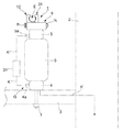
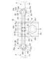
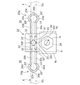
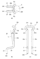
本発明に係る電線止めクリップ1は、図11に示すように、電柱(鉄塔、鉄柱、コンクリート柱、木柱等を含む)2の腕金3上に、上金具5及び下金具4が予め固定されている碍子6をボルトナット7にて固定し、上記上金具5の上に本発明に係る上記電線止めクリップ1が固定され、当該電線止めクリップ1にて架空電線E(高圧電線、低圧電線等を含む、以下単に「電線E」という)を保持するものである。
(第1の実施形態)
As shown in FIG. 11, in the electric wire stopper clip 1 according to the present invention, the upper metal fitting 5 and the lower metal fitting 4 are fixed in advance on the arm metal 3 of the utility pole (including the iron tower, the iron pillar, the concrete pillar, the wooden pillar, etc.) 2. The insulator 6 is fixed with bolts and nuts 7, and the electric wire stopper clip 1 according to the present invention is fixed on the upper metal fitting 5, and the overhead electric wire E (high-voltage electric wire, low-voltage electric wire) is fixed by the electric wire stopper clip 1. Etc., hereinafter simply referred to as "electric wire E").
(First Embodiment)

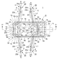
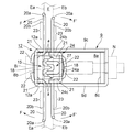
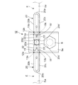
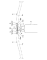
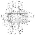
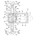
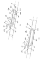
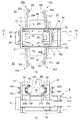
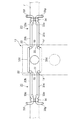
図8に示すように、上記上金具5の上面に上向きコ字状の金属製の取付金具8の底板8aの下面を上記上金具5の上面に例えば溶接により固定し、上記取付金具8の上側から、上下開口の金属製長方形枠9を、上記取付金具8の前面側起立板8bと後面側起立板8cが上記金属製長方形枠9の前面板9aと後面板9bの内側に入るように被覆する(図8矢印A参照)。 As shown in FIG. 8, the lower surface of the bottom plate 8a of the metal mounting bracket 8 having an upward U-shape is fixed to the upper surface of the upper bracket 5 by welding, for example, and the upper side of the mounting bracket 8 is formed. The metal rectangular frame 9 having the upper and lower openings is coated so that the front side standing plate 8b and the rear side standing plate 8c of the mounting bracket 8 are inside the front plate 9a and the rear surface plate 9b of the metal rectangular frame 9. (See arrow A in FIG. 8).

上記取付金具8の上記前面側起立板8bと上記後面側起立板8cには水平方向同一水準位置にボルト孔10,10が貫通形成されている。一方、上記金属製長方形枠9の前面板9aと上記後面板9bにも水平方向同一水準位置にボルト孔11,11が貫通形成されており、上記取付金具8に上記金属製長方形枠9を被覆したとき、各ボルト孔11,11及び10,10の中心が同一中心軸P上に位置し得るように構成されている(図1参照)。 Bolt holes 10 and 10 are formed through the front side upright plate 8b and the rear side upright plate 8c of the mounting bracket 8 at the same level position in the horizontal direction. On the other hand, bolt holes 11 and 11 are formed through the front plate 9a and the rear surface plate 9b of the metal rectangular frame 9 at the same level in the horizontal direction, and the mounting bracket 8 is covered with the metal rectangular frame 9. When this is done, the centers of the bolt holes 11, 11 and 10, 10 can be located on the same central axis P (see FIG. 1).

上記金属製長方形枠9は、前後方向に長い長方形状の上下開口枠から構成されており、当該金属製長方形枠9を基台として、前方側の上記前面板9aを包摂する隣接コーナ部を含む横断面コ字状の一端部が、上方に延長されることにより、横断面コ字状の電線受部12が形成されている(図1、図2、図8参照)。 The metal rectangular frame 9 is composed of a rectangular upper and lower opening frame that is long in the front-rear direction, and includes an adjacent corner portion that includes the front plate 9a on the front side based on the metal rectangular frame 9. By extending one end portion having a U-shaped cross section upward, a wire receiving portion 12 having a U-shaped cross section is formed (see FIGS. 1, 2, and 8).

尚、図1、図8(他の図においても同じ)において、上記金属製長方形枠9において、上記電線受部12が形成された側を「前方」、電線受部12が形成されていない側を「後方」、「前方」から「後方」を向いた場合の左右を「左方、右方」(外向き左右方向)、「前方」から「後方」を向いた場合の上下を「上下方向」と定義する。 In addition, in FIGS. 1 and 8 (the same applies to other figures), in the metal rectangular frame 9, the side where the electric wire receiving portion 12 is formed is "front", and the side where the electric wire receiving portion 12 is not formed is the side. "Back", left and right when facing "back" from "front" (outward left and right), and "up and down" when facing "front" to "back" Is defined.

上記電線受部12は、図1、図2、図8に示すように、下方に上記ボルト孔11が形成された上記前面板9a及び上記後面板9b、及び、左側面板9c、右側面板9dとから構成されている。 As shown in FIGS. 1, 2, and 8, the electric wire receiving portion 12 includes the front plate 9a and the rear surface plate 9b in which the bolt holes 11 are formed downward, and the left side plate 9c and the right side plate 9d. It is composed of.

上記電線受部12の両端縁には、互いに平行な左右側板12a,12bが後向きで形成されており、上記左右側板12a,12bの下端部は上記左右側面板9c,9dの上縁に一体化している(図2参照)。 Left and right side plates 12a and 12b parallel to each other are formed backward on both end edges of the electric wire receiving portion 12, and the lower ends of the left and right side plates 12a and 12b are integrated with the upper edges of the left and right side plates 9c and 9d. (See Fig. 2).

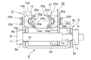
上記左右側板12a,12bには、上記左右側面板9c,9dの上縁より上方位置に、内部に左右の電線把持部20,20の上線部20b、下線部20cが各々係合する電線受用の溝13,13が後向きに各々凹設されている(図3、図5、図7、図8参照)。この溝13,13は左右対称形状なので、図2の溝13にてその形状を説明すると、当該溝13は、後方向の凹状の溝から構成されており、図7に示すように、後述の左右電線把持部20,20(上下線部20b,20c)が係合する上下のコーナ部13a,13bを有しており、後向の開口側には上側に電線受用のテーパ部13c、上記開口側の下側に電線受用のテーパ部13dが各々形成されている。 The left and right side plates 12a and 12b are for receiving electric wires in which the upper and lower wire portions 20b and the underline portions 20c of the left and right electric wire grip portions 20 and 20 are internally engaged at positions above the upper edges of the left and right side plate 9c and 9d. The grooves 13 and 13 are recessed rearward, respectively (see FIGS. 3, 5, 7, and 8). Since the grooves 13 and 13 have a symmetrical shape, the shape will be described with reference to the groove 13 in FIG. 2. The groove 13 is composed of a concave groove in the rear direction, and as shown in FIG. 7, it will be described later. It has upper and lower corner portions 13a and 13b with which the left and right wire gripping portions 20 and 20 (upper and lower wire portions 20b and 20c) are engaged. Tapered portions 13d for receiving electric wires are formed on the lower side of each side.

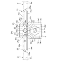
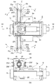
上記電線受部12の上記左右側板12a,12bの内側には、金属製の針電極15が固定されている。この針電極15は図1、図2に示すように、後向で、上方と下方に上針部15a〜15cと下針部15a’〜15c’が設けられていると共に、図1に示すように、上記上下針部が、平面視においては、左右方向に間隔を以って3個並設されており(上下針部15a,15a’、上下針部15b,15b’、上下針部15c,15c’)、これらの針電極15は、電線を把持したとき、電線Eの被覆を破って内部の金属製の導体に接触させ、電線Eの導体Ecと金属製の電線受部12とを導通させるためのものである(図3参照)。 A metal needle electrode 15 is fixed inside the left and right side plates 12a and 12b of the electric wire receiving portion 12. As shown in FIGS. 1 and 2, the needle electrode 15 is provided with upper needle portions 15a to 15c and lower needle portions 15a'to 15c' on the upper and lower sides, and as shown in FIG. In addition, three upper and lower needle portions are arranged side by side at intervals in the left-right direction in a plan view (upper and lower needle portions 15a, 15a', upper and lower needle portions 15b, 15b', upper and lower needle portions 15c, 15c'), these needle electrodes 15 break the coating of the electric wire E and come into contact with the internal metal conductor when the electric wire is gripped, and conduct the conductor Ec of the electric wire E and the metal electric wire receiving portion 12. (See FIG. 3).

この針電極15は上記電線受部12の内側の面にその前面15’(図2参照)を接触することにより、電線受部12に導通状態で接続固定されている。尚、18は貫通孔18aを介して針電極15を前面板9aに固定するための金具である(図2、図5参照)。 The needle electrode 15 is connected and fixed to the electric wire receiving portion 12 in a conductive state by contacting the front surface 15'(see FIG. 2) with the inner surface of the electric wire receiving portion 12. Reference numeral 18 denotes a metal fitting for fixing the needle electrode 15 to the front plate 9a via the through hole 18a (see FIGS. 2 and 5).

また上記電線受部12の前面板9aには、左側に、上下に貫通孔19,19’、右側に上下に貫通孔19,19’(計4個)が各々貫通形成されている(図5、図8参照)。そして、上記上側の左右の貫通孔19,19は上記左右の上記溝13,13の上側の上記コーナ部13a,13aと略同一の高さに設けられ、上記下側の左右の貫通孔19’,19’は上記左右の上記溝13,13の下側の上記コーナ部13b,13bと略同一の高さに設けられている。そして、上記左側の貫通孔19,19’に左の電線把持部20の端部20b’,20c’を、上記電線受部12の内側(後方側)から挿通して、左方向に広げられた上記電線把持部20の上下線部20b,20cが、左側の上記溝13内の上側のコーナ部13aと下側のコーナ部13bに位置するように構成されている(図5、図7(a)(b)参照)。さらに、上記右側の貫通孔19,19’に右の電線把持部20の端部20b’,20c’を、上記電線受部12の内側(後方側)から挿通して、右方向に広げられた上記電線把持部20の上下線部20b,20cが、右側の上記溝13の上側のコーナ部13aと下側のコーナ部13bに位置するように構成されている(図7(a)(b)、図5参照)。 Further, the front plate 9a of the electric wire receiving portion 12 is formed with through holes 19, 19'upper and lower on the left side and through holes 19, 19' (4 in total) on the right side, respectively (FIG. 5). , See FIG. 8). The upper left and right through holes 19 and 19 are provided at substantially the same height as the upper corner portions 13a and 13a of the left and right grooves 13 and 13, and the lower left and right through holes 19' , 19'are provided at substantially the same height as the corner portions 13b and 13b below the left and right grooves 13 and 13. Then, the ends 20b'and 20c' of the left electric wire gripping portion 20 were inserted into the left through holes 19 and 19'from the inside (rear side) of the electric wire receiving portion 12 and widened to the left. The upper and lower wire portions 20b and 20c of the electric wire grip portion 20 are configured to be located at the upper corner portion 13a and the lower corner portion 13b in the groove 13 on the left side (FIGS. 5 and 7 (a). ) (B). Further, the ends 20b'and 20c' of the right wire gripping portion 20 are inserted into the through holes 19 and 19'on the right side from the inside (rear side) of the wire receiving portion 12 and expanded to the right. The upper and lower wire portions 20b and 20c of the electric wire grip portion 20 are configured to be located at the upper corner portion 13a and the lower corner portion 13b of the groove 13 on the right side (FIGS. 7A and 7B). , See FIG. 5).

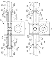
次に、電線把持部20について説明する。この電線把持部20は、上記電線受部12の左側に1個、電線受部12の右側に1個、後述の可動電線受部24の左側に1個、右側に1個、計4個を使用しているが、全て同一形状であるので、以下、1個の電線把持部20について説明する。 Next, the electric wire gripping portion 20 will be described. The electric wire gripping portion 20 has one on the left side of the electric wire receiving portion 12, one on the right side of the electric wire receiving portion 12, one on the left side of the movable electric wire receiving portion 24 described later, and one on the right side, for a total of four. Although they are used, they all have the same shape, so one electric wire gripping portion 20 will be described below.

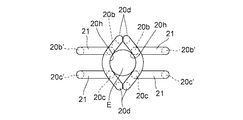
この電線把持部20は金属製(例えばステンレス(SUS304WPB等))の例えば直径約2mm〜3mmの弾性線材であり、弾性的に曲げることのできる金属線材から構成されており、基本形は図5、図9に示すように、1本の線材を、例えば半径10mmにて一端部はU字形状に折り曲げられてU字状部20aが形成され、上記U字状部20aから、互いに平行な2本の上線部20bと下線部20cが構成され、他端部は一対の端部20b’,20c’が形成されている。 The electric wire grip portion 20 is made of metal (for example, stainless steel (SUS304WPB or the like)) and is made of an elastic wire having a diameter of, for example, about 2 mm to 3 mm, and is made of a metal wire that can be elastically bent. As shown in 9, one wire rod is bent into a U-shape at one end at a radius of 10 mm, for example, to form a U-shaped portion 20a, and two wires parallel to each other are formed from the U-shaped portion 20a. An overlined portion 20b and an underlined portion 20c are formed, and a pair of end portions 20b'and 20c'are formed at the other end portion.

そして、図1、図9、図23(a)に示すように、上記他端部側の端部20b’,20c’に比較的近い上線部20bと下線部20cの同一点a,aを、同じ方向(一方向、図1においては前方側)に略直角に各々折り曲げて溝係合部21,21を形成すると共に、さらに上記各溝係合部21,21よりも上記端部20b’,20c’に近い上線部20b,下線部20cの同一点b,bを、他方向(図1においては右又は左方向)に略直角に各々折り曲げて挿通部22,22を形成することで、1つの電線把持部20が形成されている。即ち、一端はU字状部20aが形成され、他端は2本の線材からなる平面視略L字状の基端部(溝係合部21,21及び挿通部22,22)が形成されている。このように電線把持部20は予め図1、図9に示す形状に加工されている。尚、上記U字状部20aから上記一点a,aまでの上下線部20b,20cを接触部23という。 Then, as shown in FIGS. 1, 9, and 23 (a), the same points a and a of the overlined portion 20b and the underlined portion 20c that are relatively close to the ends 20b'and 20c' on the other end side are designated. The groove engaging portions 21 and 21 are formed by bending each in the same direction (one direction, the front side in FIG. 1) at substantially right angles, and the end portions 20b', rather than the groove engaging portions 21 and 21 are further formed. The same points b and b of the overlined portion 20b and the underlined portion 20c close to 20c'are bent at substantially right angles in other directions (right or left in FIG. 1) to form the insertion portions 22, 22. Two wire gripping portions 20 are formed. That is, a U-shaped portion 20a is formed at one end, and a substantially L-shaped base end portion (groove engaging portions 21, 21 and insertion portions 22, 22) made of two wire rods is formed at the other end. ing. In this way, the electric wire grip portion 20 is preliminarily processed into the shapes shown in FIGS. 1 and 9. The vertical line portions 20b and 20c from the U-shaped portion 20a to the one point a and a are referred to as contact portions 23.

そしてこの電線把持部20は、図1、図2、図5に示すように、上記端部20b’,20c’を含む上記挿通部22,22を上記電線受部12の左側の上下の貫通孔19,19’に内側から各々挿通し、U字状部20a側が上記電線受部12の左方向に位置するように回動させて、上記溝係合部21,21を上記溝13内の上下のコーナ部13a,13bに係合することで基端部(挿通部22,22及び溝係合部21,21)を以って固定し(図1、図7(a)(b)参照)、上記U字状部20aが電線受部12の外向きの左側に上下方向に(横向き)U字状になるように(水平に位置するように)、上記接触部23を上記電線受部12の左側に水平に位置させる(図1、図5参照)。 Then, as shown in FIGS. 1, 2, and 5, the electric wire gripping portion 20 inserts the insertion portions 22 and 22 including the end portions 20b'and 20c'in the upper and lower through holes on the left side of the electric wire receiving portion 12. Insert each into 19 and 19'from the inside, rotate the U-shaped portion 20a side so that it is located to the left of the wire receiving portion 12, and move the groove engaging portions 21 and 21 up and down in the groove 13. By engaging with the corner portions 13a and 13b of the above, the base end portions (insertion portions 22, 22 and groove engaging portions 21 and 21) are fixed (see FIGS. 1, 7 (a) and 7 (b)). The contact portion 23 is placed in the wire receiving portion 12 so that the U-shaped portion 20a is vertically (horizontally) U-shaped (positioned horizontally) on the outward left side of the wire receiving portion 12. Position horizontally on the left side of (see FIGS. 1 and 5).

この時点で、上記接触部23は、図1、図9に示すように、上記中心軸Pに直交する左右水平線L1に対して後方傾斜角θとして約10度だけ後方に傾斜した状態となっているが、電線を把持した状態においては、図4に示すように、上記接触部23は上記電線Eと密着し、該電線Eと平行になるように構成されている。即ち、電線Eを把持した状態では、後述の可動電線把持部24の電線把持部20の前方側への移動によって電線Eによって前方側に押され、上記接触部23の後方向きの附勢力に抗して前方に押圧され、図4に示すように上記電線把持部20を以って、電線Eに平行な状態で電線Eの側面(前方側側面Ea)を保持し得るように構成されている。即ち、左の上記電線把持部20は後方向の附勢力を上記電線Eに与えるべく、上記基端部(一点a)から上記各U字状部20aが上記可動電線受部24方向に傾斜している。 At this point, as shown in FIGS. 1 and 9, the contact portion 23 is in a state of being tilted rearward by about 10 degrees as a rearward tilt angle θ with respect to the left and right horizontal lines L1 orthogonal to the central axis P. However, in the state where the electric wire is gripped, as shown in FIG. 4, the contact portion 23 is configured to be in close contact with the electric wire E and to be parallel to the electric wire E. That is, in the state where the electric wire E is gripped, the movable electric wire gripping portion 24 is pushed forward by the electric wire E due to the movement of the electric wire gripping portion 20 to the front side, and resists the rearward urging force of the contact portion 23. As shown in FIG. 4, the electric wire gripping portion 20 is configured to be able to hold the side surface (front side surface Ea) of the electric wire E in a state parallel to the electric wire E. .. That is, in the electric wire gripping portion 20 on the left, each U-shaped portion 20a is inclined in the direction of the movable electric wire receiving portion 24 from the base end portion (one point a) in order to apply a rearward urging force to the electric wire E. ing.

また図1の状態(電線Eを把持する前)において、左の上記電線把持部20は、上記電線受部12の上記貫通孔19,19’に上記各挿通部22,22を挿通され、上記各上線部20bと上記各下線部20cを、左の上記溝13に係合した状態で、上記電線受部12にずれることなく強固に固定された状態となっている(図5参照)。 Further, in the state of FIG. 1 (before gripping the electric wire E), the electric wire gripping portion 20 on the left is inserted through the through holes 19 and 19'of the electric wire receiving portion 12 and the insertion portions 22 and 22 are inserted. Each of the overlined portions 20b and each of the underlined portions 20c are firmly fixed to the electric wire receiving portion 12 in a state of being engaged with the groove 13 on the left (see FIG. 5).

また、上記電線把持部20の上記U字状部20aは、上記上下線部20b,20cの長手方向の延長線L2上より若干前方側(電線から離れる方向)に湾曲形成された反部Hが形成されており(図1矢印R参照)、これにより、上記接触部23にて電線Eの側面を把持したとき、上記U字状部20aの反部Hの円弧部20a’(図9(a)参照)が電線Eの側面の周方向の円弧に沿って密着するように構成されている(図2、図9、図10参照)。これにより、接触部23(上下線部20b,20c)を電線Eの側面に密着させることができる(図23(a)参照)。 Further, the U-shaped portion 20a of the electric wire gripping portion 20 has a counter portion H curved slightly forward (in the direction away from the electric wire) from the extension line L2 in the longitudinal direction of the vertical wire portions 20b and 20c. It is formed (see arrow R in FIG. 1), so that when the side surface of the electric wire E is gripped by the contact portion 23, the arc portion 20a'of the counter portion H of the U-shaped portion 20a (FIG. 9 (a)). ) Are in close contact with each other along the circumferential arc on the side surface of the electric wire E (see FIGS. 2, 9, and 10). As a result, the contact portion 23 (upper and lower wire portions 20b, 20c) can be brought into close contact with the side surface of the electric wire E (see FIG. 23A).

上記電線受部12の右側の電線把持部20も、上記電線把持部20と同じ形状のものであり、上記左側の上記電線把持部20を左右反転してU字状部20aが上記電線受部12の右側に位置するように取り付けたものである。 The wire grip portion 20 on the right side of the wire receiving portion 12 also has the same shape as the wire grip portion 20, and the wire grip portion 20 on the left side is inverted left and right so that the U-shaped portion 20a is the wire receiving portion. It is attached so as to be located on the right side of 12.

即ち、右側の電線把持部20は、図1、図2、図5に示すように、上記端部20b’,20c’を含む上記挿通部22,22を上記電線受部12の右側の貫通孔19,19’に内側から挿通し、U字状部20a側が右方向に位置するように回動させて、上記溝係合部21,21を上記溝13の上下のコーナ部13a,13bに係合することで基端部(挿通部22,22及び溝係合部21,21)を以って固定し(図3、図4参照)、上記U字状部20aが電線受部12の外向きの右側に上下方向に(横向き)U字状になるように(水平に位置するように)、上記接触部23を上記電線受部12の右側に水平に位置させる(図1、図5参照)。 That is, as shown in FIGS. 1, 2, and 5, the electric wire gripping portion 20 on the right side has a through hole on the right side of the electric wire receiving portion 12 through the insertion portions 22 and 22 including the end portions 20b'and 20c'. It is inserted into 19 and 19'from the inside and rotated so that the U-shaped portion 20a side is located to the right, and the groove engaging portions 21 and 21 are engaged with the upper and lower corner portions 13a and 13b of the groove 13. By fitting, the base end portions (insertion portions 22, 22 and groove engaging portions 21 and 21) are fixed (see FIGS. 3 and 4), and the U-shaped portion 20a is outside the wire receiving portion 12. The contact portion 23 is positioned horizontally on the right side of the wire receiving portion 12 so as to form a U-shape (horizontally) in the vertical direction (horizontally) on the right side of the orientation (see FIGS. 1 and 5). ).

この時点で、上記接触部23は、図1に示すように、上記中心軸Pに直交する左右水平線L1に対して後方傾斜角θとして約10度だけ後方に傾斜した状態となっているが、電線Eを把持した状態においては、図4に示すように、上記接触部23は上記電線Eに密着し、該電線Eと略平行になるように構成されている。即ち、電線Eを把持した状態では、後述の可動電線把持部24の前方側への移動によって電線Eによって前方側に押され、上記接触部23の後方向きの附勢力に抗して前方に押圧され、図4に示すように、電線Eに平行な状態で電線Eの側面(前方側側面Ea)を保持し得るように構成されている。即ち、右の上記電線把持部20は後方向の附勢力を上記電線Eに与えるべく、上記基端部(一点a)から上記各U字状部20aが上記可動電線受部24方向に傾斜している。 At this point, as shown in FIG. 1, the contact portion 23 is in a state of being inclined backward by about 10 degrees as a rearward inclination angle θ with respect to the left and right horizontal lines L1 orthogonal to the central axis P. In the state where the electric wire E is gripped, as shown in FIG. 4, the contact portion 23 is configured to be in close contact with the electric wire E and substantially parallel to the electric wire E. That is, in the state where the electric wire E is gripped, the movable electric wire gripping portion 24, which will be described later, is pushed forward by the electric wire E due to the movement to the front side, and is pushed forward against the rearward urging force of the contact portion 23. As shown in FIG. 4, the side surface (front side surface Ea) of the electric wire E can be held in a state parallel to the electric wire E. That is, in the electric wire gripping portion 20 on the right, each U-shaped portion 20a is inclined in the direction of the movable electric wire receiving portion 24 from the base end portion (one point a) in order to apply a rearward urging force to the electric wire E. ing.

また図1の状態(電線Eを把持する前)において、右の上記電線把持部20は、上記電線受部12の上記貫通孔19,19’に上記各挿通部22,22を挿通され、上記各上線部20bと上記各下線部20cを、右の上記溝13に係合した状態で、上記電線受部12にずれることなく強固に固定された状態となっている。 Further, in the state of FIG. 1 (before gripping the electric wire E), the electric wire gripping portion 20 on the right is inserted through the through holes 19 and 19'of the electric wire receiving portion 12 and the insertion portions 22 and 22 are inserted. Each of the overlined portions 20b and each of the underlined portions 20c are firmly fixed to the electric wire receiving portion 12 in a state of being engaged with the groove 13 on the right side.

また、上記電線把持部20の上記U字状部20aは、上記上下線部20b,20cの長手方向の延長線L2上より若干前方側(電線から離れる方向)に湾曲形成された反部Hが形成されており(図1矢印R参照)、これにより、上記接触部23にて電線の側面を把持したとき、上記U字状部20aの反部Hの円弧が電線の側面の円弧に沿って密着するように構成されている(図2、図9、図10参照)。これにより、接触部23(上下線部20b,20c)を電線Eの側面に密着させることができる(図23(a)参照) Further, the U-shaped portion 20a of the electric wire gripping portion 20 has a counter portion H curved slightly forward (in the direction away from the electric wire) from the extension line L2 in the longitudinal direction of the vertical wire portions 20b and 20c. It is formed (see arrow R in FIG. 1), so that when the side surface of the electric wire is gripped by the contact portion 23, the arc of the counter portion H of the U-shaped portion 20a is along the arc of the side surface of the electric wire. It is configured to be in close contact (see FIGS. 2, 9, and 10). As a result, the contact portion 23 (upper and lower wire portions 20b, 20c) can be brought into close contact with the side surface of the electric wire E (see FIG. 23 (a)).

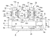
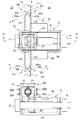
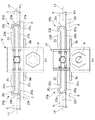
上記金属製長方形枠9の前面板9a、後面板9bに形成された上記ボルト孔11,11、及び、上記取付金具8の前面側起立板8bと後面側起立板8cに形成されたボルト孔10,10に1本の金属製のボルトBを挿通し、螺子の切っていない後端部B’にナットNを挿通して抜止ピン28(図2、図6参照)で抜け止めすることで、ボルトBを回転可能な状態として上記取付金具8に上記金属製長方形枠9を固定する(図2参照)。 The front plate 9a of the metal rectangular frame 9, the bolt holes 11 and 11 formed in the rear surface plate 9b, and the bolt holes 10 formed in the front side upright plate 8b and the rear surface side upright plate 8c of the mounting bracket 8. , 10 by inserting one metal bolt B, inserting a nut N into the unthreaded rear end B', and using a retaining pin 28 (see FIGS. 2 and 6) to prevent it from coming off. The metal rectangular frame 9 is fixed to the mounting bracket 8 with the bolt B rotatable (see FIG. 2).

上記金属製長方形枠9内におけるボルトBの雄螺子部B”には、可動電線受部24の下端の金属製の雌螺子部25を螺合して、上記ボルトBを正逆回転させることにより、上記可動電線受部(金属製)24を上記電線受部12に近接、離間し得るように構成する(図1、図2参照)。 By screwing the metal female screw portion 25 at the lower end of the movable electric wire receiving portion 24 into the male screw portion B of the bolt B in the metal rectangular frame 9, the bolt B is rotated in the forward and reverse directions. , The movable electric wire receiving portion (made of metal) 24 is configured so as to be close to and separated from the electric wire receiving portion 12 (see FIGS. 1 and 2).

上記可動電線受部24は、上記ボルトBへの螺合状態において、上記雌螺子部25に固定された直立基板24aと、該直立基板24aの左右両縁には前向きに左右側板24b,24cが平行に形成されている(図1参照)。この可動電線受部24は、上記電線受部12と対称形状であり、平面視前向き「コ」字状に形成されている。但し左右側板24b,24cの左右方向幅は金属製長方形枠9の内部に位置しているから電線受部12側より若干狭い。尚、可動電線受部24側の電線把持部20,20を「可動電線把持部20,20」という。 The movable electric wire receiving portion 24 has an upright substrate 24a fixed to the female screw portion 25 and left and right side plates 24b and 24c facing forward on both left and right edges of the upright substrate 24a in a screwed state to the bolt B. They are formed in parallel (see FIG. 1). The movable electric wire receiving portion 24 has a symmetrical shape with the electric wire receiving portion 12, and is formed in a forward-looking "U" shape in a plan view. However, since the widths of the left and right side plates 24b and 24c in the left-right direction are located inside the metal rectangular frame 9, they are slightly narrower than the wire receiving portion 12 side. The electric wire gripping portions 20 and 20 on the movable electric wire receiving portion 24 side are referred to as "movable electric wire gripping portions 20 and 20".

上記左右側板24b,24cには、上記電線受部12の上記溝13,13と同一高さに、各々溝26,26が凹設されている(図1、図2参照)。この溝26,26は左右対称形状なので、図2の溝26にてその形状を説明すると、当該溝26は、前向きの凹状の溝から構成されており、図7に示すように、後述の左右の可動電線把持部20が係合する上下のコーナ部26a,26bを有しており、前方向の開口側には上側に電線受用のテーパ部26c、上記開口側の下側に電線受用のテーパ部26dが各々形成されており、その形状は、上記電線受部12の上記溝13,13と略対称形状である(テーパ部26dとテーパ部13dの形状が異なる)。 Grooves 26 and 26 are recessed in the left and right side plates 24b and 24c at the same height as the grooves 13 and 13 of the electric wire receiving portion 12, respectively (see FIGS. 1 and 2). Since the grooves 26 and 26 have a symmetrical shape, the shape will be described with reference to the groove 26 in FIG. 2. The groove 26 is composed of a forward-facing concave groove, and as shown in FIG. 7, the left and right grooves will be described later. Has upper and lower corner portions 26a and 26b with which the movable electric wire gripping portion 20 of the above is engaged. Each of the portions 26d is formed, and the shape thereof is substantially symmetrical with the grooves 13 and 13 of the electric wire receiving portion 12 (the shapes of the tapered portion 26d and the tapered portion 13d are different).

上記可動電線受部24の上記左右側板24b,24cに挟まれた内側には、上記針電極15に対向する金属製の針電極27が固定されている(図1、図2参照)。この針電極27は図2に示すように、前方向で、上方と下方に上針部27a,27bと下針部27a’,27b’が設けられていると共に、図1に示すように、上記上下針部が、平面視においては、左右方向に間隔を以って2個並設されており(上下針部27a,27a’、上下針部27b,27b’)、これらの針電極27は、電線Eを把持したとき、電線Eの被覆を破って内部の導体Ecに接触させ、電線Eの導体と金属製の可動電線受部24とを導通させるためのものである(図3参照)。この針電極27の上記上下針部27a,27a’は、平面視において(図1参照)、対向する上記針電極15の上下針部15a,15a’と上下針部15b,15b’との中間位置、上記上下針部27b,27b’は、対向する上記針電極15の上下針部15b,15b’と上下針部15c,15c’との中間位置に位置するように構成されている。 A metal needle electrode 27 facing the needle electrode 15 is fixed inside the movable wire receiving portion 24 sandwiched between the left and right side plates 24b and 24c (see FIGS. 1 and 2). As shown in FIG. 2, the needle electrode 27 is provided with upper needle portions 27a, 27b and lower needle portions 27a', 27b' in the forward direction in the upper and lower directions, and as shown in FIG. 1, the above-mentioned needle electrode 27 is provided. In a plan view, two upper and lower needle portions are arranged side by side with an interval in the left-right direction (upper and lower needle portions 27a, 27a', upper and lower needle portions 27b, 27b'), and these needle electrodes 27 are When the electric wire E is gripped, the coating of the electric wire E is broken and brought into contact with the internal conductor Ec, so that the conductor of the electric wire E and the metal movable electric wire receiving portion 24 are made conductive (see FIG. 3). The upper and lower needle portions 27a, 27a'of the needle electrode 27 are located at intermediate positions between the upper and lower needle portions 15a, 15a'and the upper and lower needle portions 15b, 15b' of the opposing needle electrodes 15 in a plan view (see FIG. 1). The upper and lower needle portions 27b and 27b'are configured to be located at intermediate positions between the upper and lower needle portions 15b and 15b'and the upper and lower needle portions 15c and 15c'of the opposing needle electrodes 15.

この針電極27は上記可動電線受部24の直立基板24aの内側の面にその後面27’を接触することにより、導通状態で接続固定されている。尚、可動電線受部24においても、金具18が貫通孔18aを介して針電極27を直立基板24aに固定している(図2、図6参照)。針電極15は後方側に向かう末広がり状のテーパ部(図2参照)、針電極27は前方側に向かう末広がり状のテーパ部を有しており(図2参照)、最終的に電線Eを把持したときは(図3参照)、針電極15,27の各先端が電線Eの導体Ecに導通し、両テーパ部は電線Eのセンタリングを行うように構成されている。 The needle electrode 27 is connected and fixed in a conductive state by contacting the rear surface 27'with the inner surface of the upright substrate 24a of the movable electric wire receiving portion 24. Also in the movable electric wire receiving portion 24, the metal fitting 18 fixes the needle electrode 27 to the upright substrate 24a via the through hole 18a (see FIGS. 2 and 6). The needle electrode 15 has a divergent tapered portion toward the rear side (see FIG. 2), and the needle electrode 27 has a divergent tapered portion toward the front side (see FIG. 2), and finally grips the electric wire E. When this happens (see FIG. 3), the tips of the needle electrodes 15 and 27 are electrically connected to the conductor Ec of the electric wire E, and both tapered portions are configured to center the electric wire E.

また上記可動電線受部24には、左側に、上下に貫通孔30,30’、右側に上下に貫通孔30,30’(計4個)が各々貫通形成されている(図6参照)。 Further, the movable electric wire receiving portion 24 is formed with through holes 30 and 30'upper and lower on the left side and through holes 30 and 30'(4 in total) on the upper and lower sides on the right side (see FIG. 6).

そして、上記上側の左右の貫通孔30,30は上記左右の上記溝26,26の上側の上記コーナ部26a,26aと略同一の高さに設けられ、上記下側の左右の貫通孔30’,30’は上記左右の上記溝26,26の下側の上記コーナ部26b,26bと略同一の高さに設けられている。そして、上記左側の貫通孔30,30’に左の可動電線把持部20の端部20b’,20c’を、上記可動電線受部24の内側(前側)から挿通して、左方向に広げられた上記可動電線把持部20の上下線部20b,20cが、左側の上記溝26内の上側のコーナ部26aと下側のコーナ部26bに位置するように構成されている(図7(a)(b)、図6参照)。さらに、上記右側の貫通孔30,30’に右の可動電線把持部20,20の端部20b’,20c’を、上記可動電線受部24の内側(前側)から挿通して、右方向に広げられた上記可動電線把持部20の上下線部20b,20cが、右側の上記溝26の上側のコーナ部26aと下側のコーナ部26bに位置するように構成されている(図7(a)(b)、図6参照)。 The upper left and right through holes 30 and 30 are provided at substantially the same height as the upper corner portions 26a and 26a of the left and right grooves 26 and 26, and the lower left and right through holes 30' , 30'are provided at substantially the same height as the corner portions 26b, 26b below the left and right grooves 26, 26. Then, the ends 20b'and 20c' of the left movable electric wire gripping portion 20 are inserted into the left through holes 30 and 30'from the inside (front side) of the movable electric wire receiving portion 24 and expanded to the left. The vertical wire portions 20b and 20c of the movable electric wire grip portion 20 are configured to be located at the upper corner portion 26a and the lower corner portion 26b in the groove 26 on the left side (FIG. 7A). (B), see FIG. 6). Further, the ends 20b'and 20c' of the right movable electric wire gripping portions 20 and 20 are inserted into the through holes 30 and 30'on the right side from the inside (front side) of the movable electric wire receiving portion 24 to the right. The vertical line portions 20b and 20c of the expanded movable electric wire grip portion 20 are configured to be located at the upper corner portion 26a and the lower corner portion 26b of the groove 26 on the right side (FIG. 7 (a). ) (B), see FIG. 6).

上記可動電線受部24側の上記可動電線把持部20,20は、上記電線受部12側の電線把持部20,20に対して、各接触部23,23が上記電線把持部20,20の上記各接触部23,23に対向するように、上記電線受部12側の上記電線把持部20,20に対して、同一高さで、かつ平行となるように、上記可動電線受部24に固定されている(図1参照)。また、上記電線受部12側の電線把持部20,20と上記可動電線受部24側の可動電線把持部20,20は対称形状となるように構成されている。 In the movable electric wire gripping portions 20 and 20 on the movable electric wire receiving portion 24 side, the contact portions 23 and 23 are the electric wire gripping portions 20 and 20 with respect to the electric wire gripping portions 20 and 20 on the electric wire receiving portion 12 side. The movable wire receiving portion 24 is provided with the same height and parallel to the wire gripping portions 20 and 20 on the wire receiving portion 12 side so as to face the contact portions 23 and 23. It is fixed (see FIG. 1). Further, the electric wire gripping portions 20 and 20 on the electric wire receiving portion 12 side and the movable electric wire gripping portions 20 and 20 on the movable electric wire receiving portion 24 side are configured to have a symmetrical shape.

但し、可動電線受部24の左右方向幅は、上記電線受部12の左右方向幅より狭く、可動電線把持部20,20の挿通部22,22側の取付位置(貫通孔30,30と貫通孔30’,30’)の幅は、上記貫通孔19,19と貫通孔19’,19’の幅よりも狭いので、左右の可動電線把持部20,20は上記電線受部12側の電線把持部20,20よりも左右方向に近接して固定されている(図1、図4〜図6参照)。 However, the width in the left-right direction of the movable wire receiving portion 24 is narrower than the width in the left-right direction of the wire receiving portion 12, and the mounting positions (through holes 30 and 30 and through holes 30 and 30) on the insertion portions 22 and 22 of the movable wire grip portions 20 and 20. Since the width of the holes 30'and 30') is narrower than the widths of the through holes 19 and 19 and the through holes 19' and 19', the left and right movable electric wire gripping portions 20 and 20 are electric wires on the electric wire receiving portion 12 side. It is fixed closer to the left and right directions than the grip portions 20 and 20 (see FIGS. 1, 4 to 6).

そして可動電線受部24の上記可動電線把持部20は、図1、図2、図6に示すように、上記端部20b’,20c’を含む上記挿通部22,22を上記可動電線受部24の左側の貫通孔30,30’に挿通し、U字状部20a側が左方向に位置するように回動させて上記溝係合部21,21を上記溝26の上下のコーナ部26a,26bに係合することで基端部(挿通部22,22及び溝係合部21,21)を以って固定し(図7(a)(b)、図6参照)、上記U字状部20aが可動電線受部24の外向きの左側に上下方向に(横向き)U字状になるように(水平に位置するように)、上記接触部23を上記可動電線受部24の左側に水平に位置させる(図1、図6参照)。 Then, as shown in FIGS. 1, 2, and 6, the movable wire gripping portion 20 of the movable wire receiving portion 24 has the insertion portions 22, 22 including the end portions 20b'and 20c', and the movable electric wire receiving portion. The groove engaging portions 21 and 21 are inserted into the through holes 30 and 30'on the left side of the 24 and rotated so that the U-shaped portion 20a side is located to the left, and the upper and lower corner portions 26a of the groove 26. By engaging with 26b, it is fixed by the base end portions (insertion portions 22, 22 and groove engaging portions 21 and 21) (see FIGS. 7 (a) and 7 (b) and FIG. 6), and the above U-shape. The contact portion 23 is placed on the left side of the movable wire receiving portion 24 so that the portion 20a is vertically (horizontally) U-shaped (positioned horizontally) on the outward left side of the movable wire receiving portion 24. Position it horizontally (see FIGS. 1 and 6).

この時点で、上記接触部23は、図1に示すように、上記中心軸Pに直交する左右水平線L1に対して前方傾斜角θとして約10度だけ前方に傾斜した状態となっているが(図9参照)、電線Eを把持した状態においては、図4に示すように、上記接触部23は上記電線Eと略平行になるように構成されている。即ち、電線Eを把持した状態では、上記可動電線把持部24の前方側への移動によって電線Eによって後方側に押され、上記接触部23の前向きの附勢力に抗して後方に押圧され、図4に示すように、電線Eに平行な状態で電線Eの側面(後方側側面Eb)を保持し得るように構成されている。即ち、左の上記可動電線把持部20は前方向の附勢力を上記電線Eに与えるべく、上記各基端部(一点a)から上記U字状部20aが上記電線受部12方向に各々傾斜している。 At this point, as shown in FIG. 1, the contact portion 23 is in a state of being tilted forward by about 10 degrees as a forward tilt angle θ with respect to the left and right horizontal lines L1 orthogonal to the central axis P. (See FIG. 9), in the state where the electric wire E is gripped, as shown in FIG. 4, the contact portion 23 is configured to be substantially parallel to the electric wire E. That is, in the state where the electric wire E is gripped, the movable electric wire gripping portion 24 is pushed to the rear side by the electric wire E by moving to the front side, and is pushed backward against the forward urging force of the contact portion 23. As shown in FIG. 4, the side surface (rear side side surface Eb) of the electric wire E can be held in a state parallel to the electric wire E. That is, in the movable electric wire gripping portion 20 on the left, the U-shaped portion 20a is inclined in the direction of the electric wire receiving portion 12 from each base end portion (one point a) in order to apply an urging force in the front direction to the electric wire E. doing.

また、上記可動電線把持部20の上記U字状部20aは、上記上線部20b,20cの長手方向の延長線L2上より若干後方側(電線から離れる方向)に湾曲形成された反部Hが形成されており(図1矢印R’参照)、これにより、上記接触部23にて電線Eの側面を把持したとき、上記U字状部20aの反部Hの円弧部20a’が電線Eの側面の円弧に沿って密着するように構成されている(図2、図9、図10参照)。これにより、接触部23(上下線部20b,20c)を電線Eの側面に密着させることができる(図23(a)参照)。 Further, the U-shaped portion 20a of the movable electric wire grip portion 20 has a counter portion H formed so as to be slightly rearward (in a direction away from the electric wire) from the extension line L2 in the longitudinal direction of the overline portions 20b and 20c. It is formed (see arrow R'in FIG. 1), so that when the side surface of the electric wire E is gripped by the contact portion 23, the arc portion 20a'of the reverse portion H of the U-shaped portion 20a becomes the electric wire E. It is configured to be in close contact with each other along the arc on the side surface (see FIGS. 2, 9, and 10). As a result, the contact portion 23 (upper and lower wire portions 20b, 20c) can be brought into close contact with the side surface of the electric wire E (see FIG. 23A).

上記可動電線受部24の右側の可動電線把持部20も、左側の上記可動電線把持部20と同じ形状のものであり、上記左側の上記可動電線把持部20を左右反転してU字状部20aが上記電線受部12の右側に位置するように取り付けたものである。 The movable wire grip portion 20 on the right side of the movable wire receiving portion 24 also has the same shape as the movable wire grip portion 20 on the left side, and the movable wire grip portion 20 on the left side is inverted left and right to form a U-shaped portion. 20a is attached so as to be located on the right side of the electric wire receiving portion 12.

即ち、図1に示すように、右側の可動電線把持部20は、図1、図2、図6に示すように、上記端部20b’,20c’を含む上記挿通部22,22を上記可動電線受部24の右側の貫通孔30,30’に内側から挿通し、U字状部20a側が右方向に位置するように回動させて上記溝係合部21,21を上記溝26の上下のコーナ部26a,26bに係合することで基端部(挿通部22,22及び溝係合部21,21)を以って固定し(図7参照)、上記U字状部20aが可動電線受部24の外向き右側に上下方向に(横向き)U字状になるように(水平に位置するように)、上記接触部23を上記可動電線受部24の右側に水平に位置させる(図1参照)。 That is, as shown in FIG. 1, the movable electric wire gripping portion 20 on the right side can move the insertion portions 22 and 22 including the end portions 20b'and 20c' as shown in FIGS. 1, 2 and 6. Insert it into the through holes 30 and 30'on the right side of the electric wire receiving portion 24 from the inside, and rotate it so that the U-shaped portion 20a side is located in the right direction to move the groove engaging portions 21 and 21 above and below the groove 26. By engaging with the corner portions 26a and 26b of the above, the base end portions (insertion portions 22, 22 and groove engaging portions 21 and 21) are fixed (see FIG. 7), and the U-shaped portion 20a is movable. The contact portion 23 is positioned horizontally on the right side of the movable wire receiving portion 24 so as to form a U-shape (horizontally) in the vertical direction (horizontally) on the outward right side of the electric wire receiving portion 24 (so that it is positioned horizontally). (See FIG. 1).

この時点で、上記接触部23は、図1に示すように、上記中心軸Pに直交する左右水平線L1に対して前方傾斜角θとして約10度だけ前方に傾斜した状態となっているが、電線Eを把持した状態においては、図4に示すように、上記接触部23は上記電線Eと略平行になるように構成されている。即ち、電線Eを把持した状態では、後述の可動電線把持部24の前方側への移動によって電線Eによって後方側に押され、上記接触部23の前方向きの附勢力に抗して後方に押圧され、図4に示すように、電線Eに平行な状態で電線Eの側面(後方側側面Eb)を保持し得るように構成されている。即ち、右の上記可動電線把持部20は前方向の附勢力を上記電線Eに与えるべく、上記各基端部(一点a)から上記U字状部20aが上記電線受部12方向に各々傾斜している(図1参照)。 At this point, as shown in FIG. 1, the contact portion 23 is in a state of being inclined forward by about 10 degrees as a forward inclination angle θ with respect to the left and right horizontal lines L1 orthogonal to the central axis P. In the state where the electric wire E is gripped, as shown in FIG. 4, the contact portion 23 is configured to be substantially parallel to the electric wire E. That is, in the state where the electric wire E is gripped, the movable electric wire gripping portion 24, which will be described later, is pushed backward by the electric wire E due to the movement to the front side, and is pushed backward against the forward urging force of the contact portion 23. As shown in FIG. 4, the side surface (rear side side surface Eb) of the electric wire E can be held in a state parallel to the electric wire E. That is, in the movable electric wire gripping portion 20 on the right, the U-shaped portion 20a is inclined in the direction of the electric wire receiving portion 12 from each base end portion (one point a) in order to apply an urging force in the front direction to the electric wire E. (See Fig. 1).

また、上記可動電線把持部20の上記U字状部20aは、上記上下線部20b,20cの長手方向の延長線L2上より若干後方側(電線から離れる方向)に湾曲形成された反部Hが形成されており(図1矢印R’参照)、これにより、上記把持部23にて電線Eの側面を把持したとき、上記U字状部20aの反部Hの円弧が電線の側面の円弧に沿って密着するように構成されている(図10参照)。これにより、接触部23(上下線部20b,20c)を電線Eの側面に密着させることができる(図23(a)参照)。 Further, the U-shaped portion 20a of the movable electric wire grip portion 20 is curved so as to be slightly rearward (in the direction away from the electric wire) from the extension line L2 in the longitudinal direction of the vertical wire portions 20b and 20c. (See arrow R'in FIG. 1), whereby when the side surface of the electric wire E is gripped by the gripping portion 23, the arc of the reverse portion H of the U-shaped portion 20a is the arc of the side surface of the electric wire. (See FIG. 10). As a result, the contact portion 23 (upper and lower wire portions 20b, 20c) can be brought into close contact with the side surface of the electric wire E (see FIG. 23A).

このように、左側の上記可動電線把持部20と右側の上記可動電線把持部20は、各一対の上下線部20b,20cを縦方向(上下方向)に位置させた状態で水平方向の同一水準に位置しており(図6参照)、左側の上記可動電線把持部20と右側の上記可動電線把持部20は、各一対の上下線部20b,20cを縦方向(上下方向)に位置させた状態で水平方向に同一水準に位置しており、上記電線受部12の左右の上記電線把持部20,20と上記可動電線受部24の左右の上記可動電線把持部20,20は、同一水準位置に設けられている(図2、図5、図6参照)。 As described above, the movable electric wire gripping portion 20 on the left side and the movable electric wire gripping portion 20 on the right side have the same level in the horizontal direction with the pair of vertical wire portions 20b and 20c positioned in the vertical direction (vertical direction). (See FIG. 6), the movable electric wire gripping portion 20 on the left side and the movable electric wire gripping portion 20 on the right side have each pair of vertical wire portions 20b and 20c positioned in the vertical direction (vertical direction). In the state, they are located at the same level in the horizontal direction, and the left and right electric wire gripping portions 20 and 20 of the electric wire receiving portion 12 and the left and right movable electric wire gripping portions 20 and 20 of the movable electric wire receiving portion 24 are at the same level. It is provided at the position (see FIGS. 2, 5, and 6).

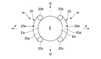
上記上金具5は(図11参照)、端子5aから金属棒K(導線)を介して電力用バリスタ31に接続され、さらに電力用バリスタ31から金属棒K、ギャップGを介して端子4aにて下金具4に接続され、下金具4から電気ケーブルK’を介して腕金3及び電柱2を介して地面に接地されている。 The upper metal fitting 5 (see FIG. 11) is connected from the terminal 5a to the power varistor 31 via a metal rod K (conductor), and further from the power varistor 31 to the terminal 4a via the metal rod K and the gap G. It is connected to the lower metal fitting 4 and is grounded from the lower metal fitting 4 to the ground via the arm metal 3 and the utility pole 2 via the electric cable K'.

本発明は上述のように構成されているので、以下、その作用について説明する。尚、前にも書いたが、可動電線受部24側の電線把持部20,20を「可動電線把持部20,20」という。 Since the present invention is configured as described above, its operation will be described below. As mentioned earlier, the electric wire gripping portions 20 and 20 on the movable electric wire receiving portion 24 side are referred to as "movable electric wire gripping portions 20 and 20".

本発明に係る電線止めクリップ1は、図11に示すように、碍子6上の上金具5上に固定され、電線受部12と可動電線受部24は図1、図2に示すように離間しており、電線受部12側の左右の電線把持部20,20と、可動電線受部24側の左右の可動電線把持部20,20間には電線Eは存在せず、上記電線受部12側の電線把持部20,20は何れも直線L1,L1に対して、一点a,aから約10度(θ)ずつ後方に傾斜しており、上記可動電線把持部24側の可動電線把持部20,20は何れも直線L1,L1に対して、一点a,aから約10度(θ)ずつ前方に傾斜しているものとする。 As shown in FIG. 11, the electric wire stopper clip 1 according to the present invention is fixed on the upper metal fitting 5 on the porcelain 6, and the electric wire receiving portion 12 and the movable electric wire receiving portion 24 are separated as shown in FIGS. 1 and 2. The electric wire E does not exist between the left and right electric wire gripping portions 20 and 20 on the electric wire receiving portion 12 side and the left and right movable electric wire gripping portions 20 and 20 on the movable electric wire receiving portion 24 side, and the electric wire receiving portion is described above. Both the electric wire gripping portions 20 and 20 on the 12 side are inclined rearward by about 10 degrees (θ) from one point a, a with respect to the straight lines L1 and L1, and the movable electric wire gripping portion 24 side on the movable electric wire gripping portion 24 side. It is assumed that the portions 20 and 20 are inclined forward by about 10 degrees (θ) from each of the points a and a with respect to the straight lines L1 and L1.

次に、一定の径の電線Eを上記電線受部12と可動電線受部24間に上記電線止クリップ1の金属製長方形枠9の長手方向に直交する方向に配置し、該電線Eを、上記電線受部12側の上記電線把持部20,20と、上記可動電線把持部24側の上記可動電線把持部20,20に沿うように、上記各電線把持部20,20と上記各可動電線把持部20,20に平行に配置する。即ち、作業者は電線Eを電線把持部20,20と可動電線把持部20,20間に平行に配置する。 Next, an electric wire E having a constant diameter is arranged between the electric wire receiving portion 12 and the movable electric wire receiving portion 24 in a direction orthogonal to the longitudinal direction of the metal rectangular frame 9 of the electric wire stop clip 1. The electric wire gripping portions 20 and 20 and the movable electric wires are aligned with the electric wire gripping portions 20 and 20 on the electric wire receiving portion 12 side and the movable electric wire gripping portions 20 and 20 on the movable electric wire gripping portion 24 side. It is arranged parallel to the grip portions 20 and 20. That is, the operator arranges the electric wire E in parallel between the electric wire grip portions 20 and 20 and the movable electric wire grip portions 20 and 20.

具体的には、上記電線Eを、図5に示すように、上記電線受部12側の左右の電線把持部20,20のU字状部20a,20aが電線Eの前方側側面Eaの軸方向の中心部に位置し、左右の上線部20b,20bと下線部20c,20cに沿って電線Eが位置するように、即ち、左右の上線部20b,20bと下線部20c,20cの中央部が電線Eの前方側側面Eaの長手方向の略中央位置に位置するように当該電線Eを配置する。 Specifically, as shown in FIG. 5, the U-shaped portions 20a and 20a of the left and right electric wire gripping portions 20 and 20 on the electric wire receiving portion 12 side form the shaft of the front side surface Ea of the electric wire E. Located in the center of the direction, so that the electric wire E is located along the left and right overlined portions 20b, 20b and underlined portions 20c, 20c, that is, the central portion of the left and right overlined portions 20b, 20b and underlined portions 20c, 20c. Arranges the electric wire E so as to be located at a substantially central position in the longitudinal direction of the front side surface Ea of the electric wire E.

このように配置すると、同時に、図6に示すように、上記電線Eは、上記可動電線受部24側の左右の可動電線把持部20,20のU字状部20a,20aが電線Eの後方側側面Ebの軸方向の中心部に対応して位置し、左右の上線部20b,20bと下線部20c,20cに沿って電線Eが位置するように、即ち、左右の上線部20b,20bと下線部20c,20cの中央部が電線Eの後方側側面Ebの長手方向の略中央位置に対応して位置することになる。 When arranged in this way, at the same time, as shown in FIG. 6, in the electric wire E, the U-shaped portions 20a and 20a of the left and right movable electric wire gripping portions 20 and 20 on the movable electric wire receiving portion 24 side are behind the electric wire E. Positioned corresponding to the axial center of the side side surface Eb, so that the electric wires E are located along the left and right upper line portions 20b and 20b and the underlined portions 20c and 20c, that is, the left and right upper line portions 20b and 20b. The central portions of the underlined portions 20c and 20c are located corresponding to the substantially central positions in the longitudinal direction of the rear side side surface Eb of the electric wire E.

かかる状態において、作業者は、上記ボルトBの頭に、六角レンチを嵌合し、当該六角レンチを右方向に回転させ、上記ボルトBを右螺子方向に回転する。すると、上記ボルトBが右螺子方向に回転するため、上記雌螺子部25を介して可動電線受部24が、電線受部12の方向に徐々に近接していく。 In such a state, the operator fits a hexagon wrench on the head of the bolt B, rotates the hexagon wrench to the right, and rotates the bolt B in the right screw direction. Then, since the bolt B rotates in the right-hand screw direction, the movable electric wire receiving portion 24 gradually approaches the electric wire receiving portion 12 via the female screw portion 25.

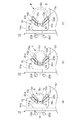
そして、上記電線受部12側の左右の電線把持部20,20の左右の接触部23,23(左右の各上線部20b,下線部20c)は、電線Eの電線受部12側の前方側側面Eaにて、上記接触部23,23の各後方側の附勢力に抗して前方側に押され、図4に示すように、電線把持部20,20の左右の上記接触部23(左右の各上線部20b,下線部20c)は、上記電線Eの前方側側面Eaに平行な状態まで押され、当該平行状態で、後方側の附勢力を電線Eの前方側側面Eaに及ぼした状態で上記電線Eの前方側側面Eaに強く接触(密着)した状態となる。 The left and right contact portions 23, 23 (each left and right upline portion 20b, underline portion 20c) of the left and right electric wire grip portions 20 and 20 on the electric wire receiving portion 12 side are on the front side of the electric wire E on the electric wire receiving portion 12 side. On the side surface Ea, the contact portions 23 and 23 are pushed forward against the urging force on the rear side, and as shown in FIG. 4, the contact portions 23 (left and right) on the left and right sides of the wire grip portions 20 and 20. Each of the upper line portion 20b and the underline portion 20c) is pushed to a state parallel to the front side side surface Ea of the electric wire E, and in the parallel state, a rearward urging force is applied to the front side side surface Ea of the electric wire E. In this state, the electric wire E is in a state of being strongly contacted (adhered) to the front side surface Ea.

このとき上記電線把持部20,20の両端のU字状部20a,20aの反部Hの円弧部20a’,20a’は、図10に示すように、上記電線Eの電線受部12側の側面(前方側側面Ea)の円弧に沿って接触した状態(電線を抱き込んだ状態)となり、これにより上記接触部23,23(上線部20b、下線部20c)が電線Eの側面に確実に接触し、ずれを生じないように構成されている。また、上記反部Hによって先端の上記U字状部20aにおける電線Eに対する曲げ応力の集中を緩和し、電線の破損を防止することができる(図23(a)参照)。 At this time, as shown in FIG. 10, the arcuate portions 20a'and 20a'of the counter portions H of the U-shaped portions 20a and 20a at both ends of the electric wire gripping portions 20 and 20 are on the electric wire receiving portion 12 side of the electric wire E. It is in a state of being in contact with the side surface (front side side Ea) along the arc (state in which the electric wire is embraced), whereby the contact portions 23 and 23 (upline portion 20b, underline portion 20c) are surely attached to the side surface of the electric wire E. It is configured so that it does not come into contact and shift. Further, the counter portion H can alleviate the concentration of bending stress on the electric wire E at the U-shaped portion 20a at the tip, and can prevent the electric wire from being damaged (see FIG. 23 (a)).

同時に、上記ボルトBの右回りの回転により、可動電線受部24側の左右の可動電線把持部20,20は(特に、両先端のU字状部20a,20aは)、上記電線Eの後方側側面Eb(可動電線受部24側の左右側面)に各々当接し、同様に上記電線Eの後方側側面Ebを前方に押圧していく。 At the same time, due to the clockwise rotation of the bolt B, the left and right movable electric wire gripping portions 20 and 20 on the movable electric wire receiving portion 24 side (particularly, the U-shaped portions 20a and 20a at both ends) are behind the electric wire E. Each side surface Eb (left and right side surfaces on the movable electric wire receiving portion 24 side) is in contact with each other, and similarly, the rear side surface Eb of the electric wire E is pressed forward.

上記可動電線受部24側の上記左右のU字状部20a,20aにて上記電線Eを前方に押していくと、上記電線Eを前方側に押していくと共に、上記電線受部12の左右の電線把持部20,20の後方向きの附勢力に抗して電線Eを前方に押していく状況になり、この状況になると、上記可動電線把持部20,20においても、これらの可動電線把持部20,20の前方向きの附勢力に抗して上記電線Eを前方に押していくことになり、上記電線受部12側の左右の電線把持部20,20が上記電線Eに平行になった状態において、略同時期に、可動電線受部24側の左右の可動電線把持部20,20が、上記電線Eの後方側側面Eb(可動電線受部24側の側面)に平行な状態となり、図4に示すように、左右の可動電線把持部20,20の上記左右の接触部23,23(左右の上線部20b,下線部20c)は、上記電線Eの後方側側面Ebに平行な状態まで押され、当該平行状態で、前方側の附勢力を電線Eの後方側側面Ebに及ぼした状態で上記電線Eの側面に強く接触(密着)した状態となる。 When the electric wire E is pushed forward by the left and right U-shaped portions 20a and 20a on the movable electric wire receiving portion 24 side, the electric wire E is pushed forward and the left and right electric wires of the electric wire receiving portion 12 are pushed. The electric wires E are pushed forward against the backward urging force of the grips 20 and 20, and in this situation, the movable electric wire grips 20 and 20 also have these movable electric wire grips 20 and 20. The electric wire E is pushed forward against the forward urging force of 20, and the left and right electric wire gripping portions 20 and 20 on the electric wire receiving portion 12 side are parallel to the electric wire E. At about the same time, the left and right movable electric wire gripping portions 20 and 20 on the movable electric wire receiving portion 24 side became parallel to the rear side side surface Eb (the side surface on the movable electric wire receiving portion 24 side) of the electric wire E, and FIG. As shown, the left and right contact portions 23, 23 (left and right upper line portions 20b, underline portion 20c) of the left and right movable electric wire grip portions 20 and 20 are pushed to a state parallel to the rear side side surface Eb of the electric wire E. In the parallel state, the urging force on the front side is applied to the rear side surface Eb of the electric wire E, and the side surface of the electric wire E is strongly contacted (adhered).

このとき左右の上記可動電線把持部20,20の両端のU字状部20a,20aの反部Hの円弧部20a’,20a’は、図10に示すように、上記電線Eの可動電線受部24側の側面(後方側側面Eb)の円弧に沿って接触した状態(電線を抱き込んだ状態)となり、これにより電線Eの側面に接触部23,23(上線部20b、下線部20c)が確実に接触し、ずれを生じないように構成されている(図23(a)参照)。また、同様に、上記反部Hによって先端の上記U字状部20aにおける電線Eに対する曲げ応力の集中を緩和し、電線の破損を防止することができる。 At this time, as shown in FIG. 10, the arcuate portions 20a'and 20a'of the counter portions H of the U-shaped portions 20a and 20a at both ends of the left and right movable electric wire gripping portions 20 and 20 are the movable electric wire receivers of the electric wire E. The side surface on the side of the portion 24 (rear side surface Eb) is in contact with the arc (the state in which the electric wire is embraced), whereby the contact portions 23 and 23 (upline portion 20b, underline portion 20c) are brought into contact with the side surface of the electric wire E. Are configured to ensure contact with each other and prevent misalignment (see FIG. 23 (a)). Similarly, the counter portion H can alleviate the concentration of bending stress on the electric wire E at the U-shaped portion 20a at the tip, and prevent the electric wire from being damaged.

上記作業者は、上記六角レンチを右方向に回転し、電線受部12の左右の電線把持部20,20、及び、可動電線受部24の左右の可動電線把持部20,20が図4に示すように電線Eの前方側側面Ea、後方側側面Ebに各々平行に接し、上記電線受部12側の左右の電線把持部20,20と、上記可動電線受部24側の左右の可動電線把持部20,20が、電線Eの前方側と後方側の両側面Ea,Ebに所定長さに亘って平行となり、上記電線Eの前方側と後方側の両側面Ea,Ebが上記左右の電線把持部20,20及び可動電線把持部20,20によって挟み込むように把持された時点で、上記六角レンチの回転を停止する。 The operator rotates the hexagonal wrench to the right, and the left and right wire grips 20 and 20 of the wire receiving portion 12 and the left and right movable wire grips 20 and 20 of the movable wire receiving portion 24 are shown in FIG. As shown, the front side side surface Ea and the rear side side surface Eb of the electric wire E are in parallel with each other, and the left and right electric wire gripping portions 20 and 20 on the electric wire receiving portion 12 side and the left and right movable electric wires on the movable electric wire receiving portion 24 side are respectively. The grip portions 20 and 20 are parallel to the front side and rear side side surfaces Ea and Eb of the electric wire E over a predetermined length, and the front side and rear side side surfaces Ea and Eb of the electric wire E are on the left and right sides. The rotation of the hexagonal wrench is stopped when the electric wires are gripped so as to be sandwiched between the electric wire grips 20 and 20 and the movable electric wire grips 20 and 20.

この状態において、左の上記電線Eは、電線受部12側の左の弾性線材からなる電線把持部20の後方向きの附勢力と、可動電線把持部24側の左の弾性線材からなる可動電線把持部20の前方向きの附勢力によって、上記各接触部23,23が電線Eに密着し、上記各接触部23,23の所定長さに亘って電線に接触し、電線Eは、電線把持部及び可動電線把持部20,20によって、軸方向に、該電線Eの前方側側面Ea及び後方側側面Ebから強く挟持された状態となる。 In this state, the left electric wire E is a movable electric wire composed of a rearward urging force of the electric wire grip portion 20 made of the left elastic wire on the electric wire receiving portion 12 side and the left elastic wire on the movable electric wire grip portion 24 side. Due to the forward urging force of the grip portion 20, each of the contact portions 23, 23 comes into close contact with the electric wire E, and comes into contact with the electric wire over a predetermined length of each of the contact portions 23, 23, and the electric wire E grips the electric wire. The portion and the movable electric wire gripping portions 20 and 20 are in a state of being strongly sandwiched from the front side side surface Ea and the rear side side surface Eb of the electric wire E in the axial direction.

同時に、右の電線Eも、上記電線受部12側の右の弾性線材からなる電線把持部20の後方向きの附勢力と、可動電線受部24側の右の弾性線材からなる可動電線把持部20の前方向きの附勢力によって、上記各接触部23,23が電線Eに密着し、上記各接触部23,23の所定長さに亘って電線に接触し、電線Eは、電線把持部及び可動電線把持部20,20によって、軸方向に、該電線Eの前方側側面Ea及び後方側側面Ebから強く挟持された状態となる。 At the same time, the right electric wire E also has a rearward urging force of the electric wire grip portion 20 made of the right elastic wire material on the electric wire receiving portion 12 side and a movable electric wire grip portion made of the right elastic wire material on the movable electric wire receiving portion 24 side. Due to the forward urging force of 20, each of the contact portions 23, 23 is in close contact with the electric wire E, and is in contact with the electric wire over a predetermined length of each of the contact portions 23, 23. The movable electric wire gripping portions 20 and 20 are in a state of being strongly sandwiched from the front side side surface Ea and the rear side side surface Eb of the electric wire E in the axial direction.

また、このとき、電線Eは、図7(a)に示すように、その前方側側面Eaは、電線把持部20,20の上下線部20b,20cに当接して上記溝13,13内において確実に支持され、その後方側側面Ebは、可動電線把持部20,20の上下線部20b,20cに当接して上記溝26,26内において確実に支持され、ずれることはない(図7(a)の電線Eの直径は10mm)。尚、電線Eの径が大の場合であっても、図7(b)に示すように(電線Eの直径は19mm)、その前方側側面Eaは、上記電線把持部20,20の上下線部20b,20cと共に、左右の上記両溝13,13の左右のテーパ部13c,13dに当接して確実に支持され、その後方側側面Ebは、上記可動電線把持部20,20の上下線部20b,20cに当接すると共に、左右の上記溝部26,26の左右のテーパ部26c,26dにも当接することで確実に支持され、大きくずれることはない。さらに電線径が大の場合であっても、電線Eの外周は、上記左右の溝13,26の範囲内においては、左右のテーパ部13c,13d及び左右のテーパ部26c,26dに接触し、確実に支持され、ずれることはない。 Further, at this time, as shown in FIG. 7A, the front side surface Ea of the electric wire E abuts on the vertical wire portions 20b and 20c of the electric wire gripping portions 20 and 20 and is formed in the grooves 13 and 13. It is securely supported, and its rear side surface Eb abuts on the vertical wire portions 20b and 20c of the movable electric wire grip portions 20 and 20 and is reliably supported in the grooves 26 and 26 and does not shift (FIG. 7 (FIG. 7). The diameter of the electric wire E in a) is 10 mm). Even when the diameter of the electric wire E is large, as shown in FIG. 7B (the diameter of the electric wire E is 19 mm), the front side surface Ea thereof is the vertical line of the electric wire gripping portions 20 and 20. Together with the portions 20b and 20c, the left and right tapered portions 13c and 13d of the left and right grooves 13 and 13 are abutted and reliably supported, and the rear side surface Eb thereof is the vertical line portion of the movable electric wire grip portions 20 and 20. By abutting on 20b and 20c and also abutting on the left and right tapered portions 26c and 26d of the left and right groove portions 26 and 26, it is reliably supported and does not deviate significantly. Further, even when the wire diameter is large, the outer circumference of the wire E comes into contact with the left and right tapered portions 13c and 13d and the left and right tapered portions 26c and 26d within the range of the left and right grooves 13 and 26. It is surely supported and does not shift.

また、かかる挟持状態において、図3、図4に示すように、電線止クリップ1の電線受部12側の針電極15の上下針部15a〜15c,15a’〜15c’及び可動電線受部24側の針電極27の上下針部27a,27b、27a’,27b’は各々上記電線Eの被覆E’を破って内部の導体Ecに接触し、電線止クリップ1との導通状態を実現し得る。また上記針電極15,27の左右の電線Eの所定長に亘り電線把持部20,20及び可動電線把持部20,20にて電線Eを弾性的に把持し得るので、針電極近傍での電線Eの応力集中を防止し得て、電線止クリップ1の放電機能が害されることがない。 Further, in such a pinched state, as shown in FIGS. 3 and 4, the upper and lower needle portions 15a to 15c, 15a'to 15c'and the movable wire receiving portion 24 of the needle electrode 15 on the wire receiving portion 12 side of the wire stop clip 1 The upper and lower needle portions 27a, 27b, 27a', 27b'of the side needle electrode 27 can break the coating E'of the electric wire E and come into contact with the inner conductor Ec, respectively, to realize a conductive state with the electric wire stop clip 1. .. Further, since the electric wire E can be elastically gripped by the electric wire gripping portions 20 and 20 and the movable electric wire gripping portions 20 and 20 over the predetermined lengths of the left and right electric wires E of the needle electrodes 15 and 27, the electric wire in the vicinity of the needle electrode The stress concentration of E can be prevented, and the discharge function of the wire stop clip 1 is not impaired.

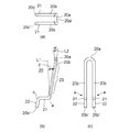
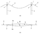
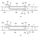
実際には、電線Eは、図13(a)に示されるように、複数の電柱2,2・・・間の各腕金3,3・・・上の各電線止クリップ1に順次、同様に固定されていく。図12に示すように、電線Eは、比較的硬質なものであり、当該電線止めクリップ1の両側における上記電線把持部20,20及び可動電線把持部20,20によって挟持された部分S,Sは、上記電線把持部20,20に平行な状態を保持し、上記部分S,Sより先の部分が図13(a)に示すように、緩やかに下に凸状になるように、各電柱2,2・・・間に掛け渡されていく。 Actually, as shown in FIG. 13A, the electric wire E is sequentially applied to the electric wire stop clips 1 on the arms 3, 3 ... Between the plurality of utility poles 2, 2 ... It will be fixed to. As shown in FIG. 12, the electric wire E is relatively hard, and the portions S, S sandwiched by the electric wire grip portions 20, 20 and the movable electric wire grip portions 20, 20 on both sides of the electric wire stop clip 1. Holds a state parallel to the electric wire gripping portions 20 and 20, and each electric pole is formed so that the portions ahead of the portions S and S are gently convex downward as shown in FIG. 13 (a). It will be passed between 2, 2 ...

このとき風により、上記電線Eは図13(b)に示すように、その中央部Mを最も大きな振幅を以って前後方向(矢印F,F’方向)に振動する。この場合、電線Eの電線止クリップ1の左右両側において、電線Eの前方側と後方側の円弧状の両側面Ea,Ebは、電線把持部20,20と、可動電線把持部20,20の接触部23,23によって、長手方向の所定範囲に亘って挟持されているので、上記電線Eが前後方向(図4、矢印F,F’方向)に振動したとしても、弾性線材から構成されている上記電線把持部20,20及び可動電線把持部20,20は、上記電線Eの前後方向の振動に合わせて、上記一点a,a近傍を支点として、上記U字状部20aを含む上記接触部23,23全体が、前後方向(図4の矢印F,F’方向)に弾性変形して振動するため、電線Eの上記接触部23,23が接触している挟持部(電線Eの軸方向の所定長さ)における特定の部位に応力が集中することがなく、従って、振動による電線Eの劣化、或いは断線等の事故を極めて効果的に防止することができる。 At this time, as shown in FIG. 13B, the electric wire E vibrates in the front-rear direction (arrows F, F'direction) with the largest amplitude in the central portion M due to the wind. In this case, on the left and right sides of the electric wire stop clip 1 of the electric wire E, the arc-shaped both side surfaces Ea and Eb on the front side and the rear side of the electric wire E are the electric wire gripping portions 20 and 20 and the movable electric wire gripping portions 20 and 20. Since the electric wires E are sandwiched by the contact portions 23 and 23 over a predetermined range in the longitudinal direction, even if the electric wire E vibrates in the front-rear direction (FIG. 4, arrows F, F'direction), it is composed of an elastic wire. The electric wire gripping portions 20, 20 and the movable electric wire gripping portions 20, 20 include the U-shaped portion 20a with the vicinity of the one point a, a as a fulcrum in accordance with the vibration of the electric wire E in the front-rear direction. Since the entire portions 23 and 23 elastically deform and vibrate in the front-rear direction (directions of arrows F and F'in FIG. 4), the holding portions (axis of the electric wire E) in which the contact portions 23 and 23 of the electric wire E are in contact with each other. Since the stress does not concentrate on a specific portion in the predetermined length in the direction), it is possible to extremely effectively prevent an accident such as deterioration or disconnection of the electric wire E due to vibration.

特に、電線Eは前方側側面Eaと後方側側面Ebとが電線把持部及び可動電線把持部20,20によって所定長さに亘って対向するバネ力によって強く挟持された状態となり、電線Eが振動しても、所定長さの電線把持部20,20及び可動電線把持部20,20も電線と共に弾性的に振動するので(例えば図4にて、電線が矢印F(F’)方向に振動したとき、電線把持部20(可動電線把持部20)は矢印F(F’)方向に変形し得るが、可動電線把持部20(電線把持部20)も前方(後方)に附勢されているので、F(F’)方向に電線Eの変形に追従し得して変形し得る)、電線Eの所定長さに亘って、挟持箇所の特定部位への応力集中を分散することができる。また、電線把持部20,20の基端部が電線を確実に支持することも加わり、電線の動きによる応力集中が、針電極近傍で起きることがなく、放電機能にも影響を与えない。 In particular, the electric wire E is in a state in which the front side surface Ea and the rear side side surface Eb are strongly sandwiched by the electric wire gripping portions and the movable electric wire gripping portions 20 and 20 by the spring force facing each other over a predetermined length, and the electric wire E vibrates. Even so, the electric wire grips 20 and 20 and the movable electric wire grips 20 and 20 having a predetermined length also vibrate elastically together with the electric wire (for example, in FIG. 4, the electric wire vibrates in the direction of arrow F (F'). At this time, the electric wire grip portion 20 (movable electric wire grip portion 20) can be deformed in the direction of the arrow F (F'), but since the movable electric wire grip portion 20 (electric wire grip portion 20) is also urged forward (rear). , It can follow the deformation of the electric wire E in the F (F') direction and can be deformed), and it is possible to disperse the stress concentration on the specific portion of the pinched portion over the predetermined length of the electric wire E. Further, the base end portions of the electric wire gripping portions 20 and 20 reliably support the electric wire, so that stress concentration due to the movement of the electric wire does not occur in the vicinity of the needle electrode and does not affect the discharge function.

また、電線把持部20と可動電線把持部20は、縦方向(上下方向)の上線部20bと下線部20cによって電線の円弧状の前方側側面Eaと後方側側面Ebとを、所定長さに亘り弾性的に挟持する構成であるから、電線の前後方向の振動に追従し易くなり、電線に対する曲げ応力の集中を効果的に分散し得る。 Further, the electric wire gripping portion 20 and the movable electric wire gripping portion 20 have the arc-shaped front side surface Ea and the rear side side surface Eb of the electric wire set to a predetermined length by the upper line portion 20b and the underline portion 20c in the vertical direction (vertical direction). Since it is elastically sandwiched over the wire, it is easy to follow the vibration of the electric wire in the front-rear direction, and the concentration of bending stress on the electric wire can be effectively dispersed.

しかも、電線の前方側側面Eaを2本の上線部20bと下線部20c(接触部23,23)によって上下間隔を開けた状態で保持し、電線の円弧状の後方側側面Ebを2本の上線部20bと下線部20cにて上下間隔を開けた状態で電線の円弧状の側面を保持するものであるから、電線の前後方向の動き(図10矢印F,F’方向)だけでなく、例えば上下方向の動き(図10矢印Q,Q’方向)にも追従することができ、電線の多方面の動きに追従し得て、電線に対する応力の集中を効果的に分散し得る。 Moreover, the front side surface Ea of the electric wire is held by the two upper line portions 20b and the underline portion 20c (contact portions 23, 23) in a vertically spaced state, and the arc-shaped rear side side surface Eb of the electric wire is held by two. Since the arcuate side surface of the electric wire is held with the upper line portion 20b and the underline portion 20c spaced apart from each other, not only the movement of the electric wire in the front-rear direction (in the directions of arrows F and F'in FIG. For example, it can follow the movement in the vertical direction (directions of arrows Q and Q'in FIG. 10), can follow the movement in various directions of the electric wire, and can effectively disperse the concentration of stress on the electric wire.

また、電線把持部20(可動電線把持部20も同じ)のU字状部20aは電線から離間する方向の反部Hが形成されているので、上記反部Hから上線部20b、下線部20cにて電線を抱き込むように密着し得るため、電線把持部20の先端部における電線の曲げ応力集中を効果的に分散し得る。 Further, since the U-shaped portion 20a of the electric wire gripping portion 20 (the same applies to the movable electric wire gripping portion 20) has a counter portion H formed in the direction away from the electric wire, the overline portion 20b and the underline portion 20c are formed from the counter portion H. Since the electric wire can be brought into close contact with each other so as to embrace the electric wire, the bending stress concentration of the electric wire at the tip of the electric wire grip portion 20 can be effectively dispersed.

以上のように、電線止クリップ1の左右両側において電線Eを確実に挟持することができ、これにより電線把持部20と可動電線把持部20が電線Eに密着して電線Eの振動に追従し得るため、電線Eへの曲げ応力を均等に分散することができる。 As described above, the electric wire E can be securely sandwiched on both the left and right sides of the electric wire stop clip 1, whereby the electric wire gripping portion 20 and the movable electric wire gripping portion 20 come into close contact with the electric wire E and follow the vibration of the electric wire E. Therefore, the bending stress on the electric wire E can be evenly distributed.

電線Eの、電線把持部20(可動電線把持部20も同じ)の上線部20b、下線部20cとの接触部23は、電線Eの側部中央からやや上下に離れた外周の途中となる。風圧荷重等により電線Eが振動する際は、電線Eがその外周を、所定長さに亘り、上記上線部20b、下線部20cとの間にはさみ入れることで、素線間摩耗(電線内のアルミ素線同士が接触した状態で摺動し、素線に摩耗が生じる現象)を軽減し、電線把持部20のばね変形による弾性力(反発力)が曲げ応力を分散することができる。よって、曲げ応力の分散効果と素線間摩耗の軽減効果を高めることができる。 The contact portion 23 of the electric wire E with the upper line portion 20b and the underline portion 20c of the electric wire grip portion 20 (the same applies to the movable electric wire grip portion 20) is in the middle of the outer circumference slightly separated from the center of the side portion of the electric wire E. When the electric wire E vibrates due to a wind pressure load or the like, the electric wire E sandwiches the outer circumference thereof between the overlined portion 20b and the underlined portion 20c over a predetermined length, thereby causing wear between the wires (inside the electric wire). The phenomenon that the aluminum wires slide in contact with each other and the wires are worn) can be reduced, and the elastic force (repulsive force) due to the spring deformation of the wire grip portion 20 can disperse the bending stress. Therefore, the effect of dispersing bending stress and the effect of reducing wear between strands can be enhanced.

また、U字状の折り返し部分の先端は、電線振幅方向に沿って反部Hを設けることにより、電線Eへの強い押圧から後退し、接触部23と同様に電線Eの外周に沿うことになる。そのため、電線把持部20の先端側に弾性力は偏りにくい。このことは、接触部23から反部Hの範囲に曲げ応力を分散させるように作用し、更に曲げ応力の分散により素線間摩耗の軽減効果を高めることができる。 Further, the tip of the U-shaped folded portion is retreated from the strong pressure on the electric wire E by providing the counter portion H along the electric wire amplitude direction, and is along the outer periphery of the electric wire E like the contact portion 23. Become. Therefore, the elastic force is less likely to be biased toward the tip end side of the electric wire grip portion 20. This acts to disperse the bending stress in the range from the contact portion 23 to the counter portion H, and further, the effect of reducing the wear between the strands can be enhanced by dispersing the bending stress.

(第2の実施形態)
次に、第2の実施形態について説明する。
尚、上記第1の実施形態と同一部分については同一符号を付し、それらの説明は便宜上省略する。
(Second Embodiment)
Next, the second embodiment will be described.
The same parts as those in the first embodiment are designated by the same reference numerals, and the description thereof will be omitted for convenience.

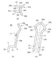
図14(a)〜(c)に示すように、電線把持部20は、金属製の弾性線材から構成されている点、及び、端部20b’,20c’側の形状、即ち、溝係合部21,21、挿通部22,22(即ち基端部)の形状は第1の実施形態の電線把持部20と同じであるが、折り返し部の形状が、第1の実施形態ではU字状部20aであるのに対し、第2の実施形態では菱形部20gである点が異なる。尚、電線受部12側と可動電線受部24側に使用する4本の電線把持部20(可動電線把持部20)は全て同一形状なので1個の電線把持部20について説明する。 As shown in FIGS. 14 (a) to 14 (c), the electric wire grip portion 20 has a point formed of a metal elastic wire and a shape on the end portions 20b'and 20c', that is, groove engagement. The shapes of the portions 21 and 21 and the insertion portions 22 and 22 (that is, the base end portion) are the same as those of the electric wire grip portion 20 of the first embodiment, but the shape of the folded portion is U-shaped in the first embodiment. The difference is that the portion 20a is a diamond-shaped portion 20g in the second embodiment. Since the four electric wire gripping portions 20 (movable electric wire gripping portions 20) used on the electric wire receiving portion 12 side and the movable electric wire receiving portion 24 side all have the same shape, one electric wire gripping portion 20 will be described.

より詳細に説明すると、上記菱形部20gは、図14(c)の側面図をみると、上線部20b、下線部20cの他端から、上線部20bと下線部20c間の間隔を広げる方向に一旦、拡幅して菱形の一対の屈曲部20d,20dを形成した後、上線部20bと下線部20c間の仮想中心線L3上に先端屈曲部20eが形成され、上記屈曲部20d,20dと上記先端屈曲部20eにより菱形部20gが形成されている。 More specifically, when looking at the side view of FIG. 14C, the diamond-shaped portion 20g is in a direction of widening the distance between the overlined portion 20b and the underlined portion 20c from the other ends of the overlined portion 20b and the underlined portion 20c. Once the width is widened to form a pair of rhombic bent portions 20d and 20d, the tip bent portion 20e is formed on the virtual center line L3 between the overlined portion 20b and the underlined portion 20c, and the bent portions 20d and 20d and the above-mentioned bent portions 20d and 20d are formed. A rhombic portion 20g is formed by the tip bending portion 20e.

そして、上記一対の屈曲部20d,20dは、図14(b)の平面図をみると、上線部20b、下線部20cから拡幅しているのみならず、上記溝係合部21,21とは逆方向(電線E側)に「く」字状に屈曲している(図23(b)参照)。これにより、上記菱形部20gの先端屈曲部20eは、図18、図23(b)に示すように、電線Eの前方側側面Eaの軸方向に沿う湾曲部20f(電線受部12側)と、電線Eの後方側側面Ebの軸方向に沿う湾曲部20f(可動電線受部24側)が形成されていると共に、図23(a)に示すように、電線Eの円周方向に沿う湾曲部20hが形成されている。 Looking at the plan view of FIG. 14B, the pair of bent portions 20d and 20d are not only widened from the overlined portions 20b and the underlined portions 20c, but are also different from the groove engaging portions 21 and 21. It is bent in a dogleg shape in the opposite direction (on the wire E side) (see FIG. 23 (b)). As a result, as shown in FIGS. 18 and 23 (b), the tip bent portion 20e of the diamond-shaped portion 20g becomes a curved portion 20f (electric wire receiving portion 12 side) along the axial direction of the front side surface Ea of the electric wire E. , A curved portion 20f (movable electric wire receiving portion 24 side) along the axial direction of the rear side surface Eb of the electric wire E is formed, and as shown in FIG. 23 (a), the curved portion 20f along the circumferential direction of the electric wire E is formed. The portion 20h is formed.

また、図14(b)に示すように、上下線部20b,20cは、左右水平線L1,L1に対して後方傾斜角θ又は前方傾斜角θ(例えばθ=約10度)として後方又は前方に傾斜している点は第1の実施形態の電線把持部20と同じである(図15参照)。 Further, as shown in FIG. 14B, the vertical line portions 20b and 20c are rearwardly or forwardly set with a rearward inclination angle θ or a forward inclination angle θ (for example, θ = about 10 degrees) with respect to the left and right horizontal lines L1 and L1. The point of inclination is the same as that of the electric wire grip portion 20 of the first embodiment (see FIG. 15).

そして、図15、図16、図19に示すように、電線受部12に、電線把持部20,20の基端部(溝係合部21、挿通部22)が第1の実施形態と同様に固定され、上記上下線部20b,20c及び上記菱形部20g,20gが上記電線受部12の左右に水平になるように固定され、電線受部12に固定された状態で、左右の上下線部20b,20cは、左右水平線L1,L1に対して後方に傾斜角θ(例えばθ=約10度)に傾斜している。 Then, as shown in FIGS. 15, 16 and 19, the electric wire receiving portion 12 has the base end portions (groove engaging portion 21, insertion portion 22) of the electric wire gripping portions 20 and 20 as in the first embodiment. The upper and lower wire portions 20b and 20c and the diamond-shaped portions 20g and 20g are fixed so as to be horizontal to the left and right of the electric wire receiving portion 12, and are fixed to the electric wire receiving portion 12 on the left and right vertical wires. The portions 20b and 20c are inclined rearward at an inclination angle θ (for example, θ = about 10 degrees) with respect to the left and right horizontal lines L1 and L1.

さらに、図15、図16、図20に示すように、可動電線受部24に、可動電線把持部20,20の基端部(溝係合部21、挿通部22)が第1の実施形態と同様に固定され、上記上下線部20b,20c及び上記菱形部20g,20gが上記可動電線受部24の左右に水平になるように固定され、可動電線受部12に固定された状態で、左右の上下線部20b,20cは、左右水平線L1,L1に対して前方に傾斜角θ(例えばθ=約10度)に傾斜している。 Further, as shown in FIGS. 15, 16 and 20, the movable electric wire receiving portion 24 has the base end portions (groove engaging portion 21, insertion portion 22) of the movable electric wire gripping portions 20 and 20 in the first embodiment. The vertical wire portions 20b and 20c and the diamond-shaped portions 20g and 20g are fixed so as to be horizontal to the left and right of the movable electric wire receiving portion 24, and are fixed to the movable electric wire receiving portion 12. The left and right vertical line portions 20b and 20c are inclined forward with respect to the left and right horizontal lines L1 and L1 at an inclination angle θ (for example, θ = about 10 degrees).

また、図15に示すように、かかる状態において、菱形部20g,20gの上記屈曲部20d,20dは互いに対向する方向に位置するように、相互に略対称となるように取り付けられている。尚、可動電線受部24の可動電線把持部20,20の取付位置は、電線受部12の電線把持部20,20の取付位置より中央部方向に近接しているので、上記電線把持部20,20の屈曲部20d,20dの位置より、可動電線把持部20,20の屈曲部20d,20dの位置は中央部よりに位置している。 Further, as shown in FIG. 15, in such a state, the bent portions 20d and 20d of the rhombic portions 20g and 20g are attached so as to be located in directions facing each other so as to be substantially symmetrical with each other. Since the mounting positions of the movable wire gripping portions 20 and 20 of the movable wire receiving portion 24 are closer to the central portion than the mounting positions of the wire gripping portions 20 and 20 of the wire receiving portion 12, the wire gripping portion 20 is described above. , 20 from the positions of the bent portions 20d and 20d, the positions of the bent portions 20d and 20d of the movable electric wire grip portions 20 and 20 are located closer to the central portion.

第2の実施形態は上述のように構成されているので、以下、その作用について説明する。
第2の実施形態の電線止めクリップ1は、第1の実施形態と同様に、図11に示すように、上金具5上に固定され、電線受部12と可動電線受部24は図15、図16に示すように離間しており、電線受部12側の左右の電線把持部20,20と、可動電線受部24側の左右の可動電線把持部20,20間には電線Eは存在せず、上記電線受部12側の電線把持部20,20は何れも直線L1,L1に対して、一点a,aから約10度ずつ後方に傾斜しており、上記可動電線把持部24側の可動電線把持部20,20は何れも直線L1に対して、一点a,aから約10度ずつ前方に傾斜しているものとする。
Since the second embodiment is configured as described above, its operation will be described below.
As shown in FIG. 11, the electric wire stopper clip 1 of the second embodiment is fixed on the upper metal fitting 5 as shown in FIG. 11, and the electric wire receiving portion 12 and the movable electric wire receiving portion 24 are shown in FIG. As shown in FIG. 16, the wires E are separated between the left and right wire gripping portions 20 and 20 on the wire receiving portion 12 side and the left and right movable wire gripping portions 20 and 20 on the movable wire receiving portion 24 side. Instead, the wire grips 20 and 20 on the wire receiving portion 12 side are all inclined rearward by about 10 degrees from each point a, a with respect to the straight lines L1 and L1, and the movable wire grip portion 24 side. It is assumed that the movable electric wire gripping portions 20 and 20 of the above are inclined forward by about 10 degrees from each of the points a and a with respect to the straight line L1.

次に、一定の径の電線Eを上記電線受部12と可動電線受部24間に上記電線止クリップ1の金属製長方形枠9の長手方向に直交する方向に配置し、該電線Eを、上記電線受部12側の上記電線把持部20,20と、上記可動電線受部24側の上記可動電線把持部20,20に沿うように、上記各電線把持部20,20と上記各可動電線把持部20,20に平行に配置する(図18参照)。即ち、作業者は電線Eを電線把持部20,20と可動電線把持部20,20間に平行に配置する。 Next, an electric wire E having a constant diameter is arranged between the electric wire receiving portion 12 and the movable electric wire receiving portion 24 in a direction orthogonal to the longitudinal direction of the metal rectangular frame 9 of the electric wire stop clip 1. The electric wire gripping portions 20 and 20 and the movable electric wires are aligned with the electric wire gripping portions 20 and 20 on the electric wire receiving portion 12 side and the movable electric wire gripping portions 20 and 20 on the movable electric wire receiving portion 24 side. It is arranged parallel to the grip portions 20 and 20 (see FIG. 18). That is, the operator arranges the electric wire E in parallel between the electric wire grip portions 20 and 20 and the movable electric wire grip portions 20 and 20.

具体的には、上記電線Eを、図19に示すように、上記電線受部12側の左右の電線把持部20,20の菱形部20g,20gの先端屈曲部20e,20eが電線Eの前方側側面Eaの軸方向の中心線L4に位置し、左右の上線部20b,20bと下線部20c,20cに沿って電線Eが位置するように、即ち、左右の上線部20b,20bと下線部20c,20cの間隔の中央部が、電線Eの前方側側面Eaの長手方向の略中央位置に位置するように当該電線Eを配置する。 Specifically, as shown in FIG. 19, the wire E is the diamond-shaped portions 20g of the left and right wire gripping portions 20 and 20 on the wire receiving portion 12 side, and the tip bending portions 20e and 20e of the 20g are in front of the wire E. It is located at the center line L4 in the axial direction of the side side surface Ea so that the electric wires E are located along the left and right overlined portions 20b and 20b and the underlined portions 20c and 20c, that is, the left and right overlined portions 20b and 20b and the underlined portion. The electric wire E is arranged so that the central portion of the interval of 20c and 20c is located at a substantially central position in the longitudinal direction of the front side surface Ea of the electric wire E.

このように配置すると、同時に、図20に示すように、上記電線Eは、上記可動電線受部24側の左右の可動電線把持部20,20の菱形部20g,20gの各先端屈曲部20e,20eが電線Eの後方側側面Ebの軸方向の中心線L4に対応して位置し、左右の上線部20b,20bと下線部20c,20cに沿って電線Eが位置するように、即ち、左右の上線部20b,20bと下線部20c,20cの間隔の中央部が、電線Eの後方側側面Ebの長手方向の略中央位置に対応して位置することになる。 When arranged in this way, at the same time, as shown in FIG. 20, the electric wire E is a bent end portion 20e of each of the diamond-shaped portions 20 g and 20 g of the left and right movable electric wire grip portions 20 and 20 on the movable electric wire receiving portion 24 side. 20e is located corresponding to the axial center line L4 of the rear side surface Eb of the electric wire E, and the electric wire E is positioned along the left and right overlined portions 20b and 20b and the underlined portions 20c and 20c, that is, left and right. The central portion of the distance between the overlined portions 20b and 20b and the underlined portions 20c and 20c is located corresponding to a substantially central position in the longitudinal direction of the rear side surface Eb of the electric wire E.

かかる状態において、作業者は、上記ボルトBの頭に、六角レンチを嵌合し、当該六角レンチを右方向に回転させ、上記ボルトBを右螺子方向に回転する。すると、上記ボルトBが右螺子方向に回転するため、上記雌螺子部25を介して可動電線受部24が、電線受部12の方向に徐々に近接していく。 In such a state, the operator fits a hexagon wrench on the head of the bolt B, rotates the hexagon wrench to the right, and rotates the bolt B in the right screw direction. Then, since the bolt B rotates in the right-hand screw direction, the movable electric wire receiving portion 24 gradually approaches the electric wire receiving portion 12 via the female screw portion 25.

そして、電線把持部20,20の先端の左右の上下湾曲部20f,20f及び湾曲部20hに電線Eの前方側側面Eaが接触し、上記前方側側面Ea,Eaにて電線把持部20,20の接触部23,23の各後方側の附勢力に抗して前方側に押され、図18に示すように、電線把持部20,20の左右の上記接触部23(左右の各上線部20b,下線部20c)は、上記電線Eの前方側側面Eaに平行な状態まで押され、当該平行状態で、後方側の附勢力を電線Eの前方側側面Eaに及ぼした状態で上記電線Eの前方側側面Eaに強く接触(密着)した状態となる。 Then, the front side surface Ea of the electric wire E comes into contact with the left and right vertical curved portions 20f, 20f and the curved portion 20h at the tips of the electric wire grip portions 20, 20, and the electric wire grip portions 20, 20 are formed at the front side side surfaces Ea, Ea. The contact portions 23 and 23 are pushed forward against the urging force on the rear side, and as shown in FIG. , The underlined portion 20c) is pushed to a state parallel to the front side surface Ea of the electric wire E, and in the parallel state, the rear side biasing force is applied to the front side surface Ea of the electric wire E. It is in a state of being in strong contact (adhesion) with the front side surface Ea.

このとき上記電線把持部20,20の両端の菱形部20g,20gの湾曲部20f,20fに案内されて、先端屈曲部20e,20eに電線Eの前方側側縁Eaが入り込み(図21(a)、図23(b)参照)、電線Eの周方向の円弧が湾曲部20hに沿って位置し(図22参照)、これにより電線Eの上記中心線L4が上記電線把持部20,20の上線部20b、下線部20cの中間部に位置し、電線把持部20,20に対して電線Eがずれないように構成される(図19参照)。 At this time, the front side edge Ea of the electric wire E enters the tip bent portions 20e and 20e by being guided by the rhombic portions 20g and the curved portions 20f and 20f of the electric wire grip portions 20 and 20 at both ends (FIG. 21 (a). ), FIG. 23 (b)), an arc in the circumferential direction of the electric wire E is located along the curved portion 20h (see FIG. 22), whereby the center line L4 of the electric wire E becomes the electric wire gripping portions 20 and 20. It is located in the middle of the overlined portion 20b and the underlined portion 20c, and is configured so that the electric wire E does not shift with respect to the electric wire gripping portions 20 and 20 (see FIG. 19).

同様に、可動電線把持部20,20の両端の菱形部20g,20gの湾曲部20f,20fに案内されて、先端屈曲部20e,20eに電線Eの後方側側縁Ebが入り込み(図23(b)参照)、電線Eの周方向の円弧が湾曲部20hに沿って位置し(図22参照)、これにより電線Eの上記中心線L4が上記可動電線把持部20,20の上線部20b、下線部20cの中間部に位置し、上記可動電線把持部20,20に対して電線Eがずれないように構成されている(図20参照)。 Similarly, the rear side edge Eb of the electric wire E enters the tip bent portions 20e and 20e guided by the rhombic portions 20g and the curved portions 20f and 20f of the movable electric wire grip portions 20 and 20 (FIG. 23 (FIG. 23). b)), the arc in the circumferential direction of the electric wire E is located along the curved portion 20h (see FIG. 22), whereby the center line L4 of the electric wire E becomes the overlined portion 20b of the movable electric wires gripping portions 20, 20. It is located in the middle of the underlined portion 20c, and is configured so that the electric wire E does not shift with respect to the movable electric wire gripping portions 20 and 20 (see FIG. 20).

そして、上記ボルトBの右回りの回転により、可動電線受部24側の左右の可動電線把持部20,20は(特に、両先端の菱形部20g,20gは)、上記電線Eの後方側側面Eb(可動電線受部24側の左右側面)に各々当接し、同様に上記電線Eの後方側側面Ebを前方に押圧していく。このとき、上記電線把持部20,20の上記菱形部20g,20gの上記屈曲部20d,20dは、各々電線Eの前方側側面Ea側(後方側)に屈曲し、かつ、上記可動電線把持部20,20の上記菱形部20g,20gの上記屈曲部20d,20dは、各々電線Eの後方側側面Eb側(前方側)に屈曲しているので、左側において、上下の屈曲部20d,20dにより電線Eの前方側側面Eaと後方側側面Ebを包み込む状態となり、右側においても同様に、上下の屈曲部20d,20dにより電線Eの前方側側面Eaと後方側側面Ebを包み込む状態となり(図18、図22参照)、電線把持部20,20及び可動電線把持部20,20により電線Eを挟持していく過程において、電線Eの電線把持部20,20及び可動電線把持部20,20からの外れを防止して、安定して電線Eを挟持していくことができる。 Then, due to the clockwise rotation of the bolt B, the left and right movable electric wire gripping portions 20 and 20 on the movable electric wire receiving portion 24 side (particularly, the diamond-shaped portions 20g and 20g at both ends) are placed on the rear side surface of the electric wire E. Each of them abuts on Eb (left and right side surfaces on the movable electric wire receiving portion 24 side), and similarly presses the rear side side surface Eb of the electric wire E forward. At this time, the diamond-shaped portions 20g of the electric wire grip portions 20 and 20 and the bent portions 20d and 20d of the 20 g are bent toward the front side side surface Ea side (rear side) of the electric wire E, respectively, and the movable electric wire grip portion. Since the diamond-shaped portions 20g of 20 and 20 and the bent portions 20d and 20d of 20 g are bent toward the rear side side surface Eb side (front side) of the electric wire E, respectively, the upper and lower bent portions 20d and 20d are formed on the left side. The front side surface Ea and the rear side surface Eb of the electric wire E are wrapped, and similarly, the front side side surface Ea and the rear side surface Eb of the electric wire E are wrapped by the upper and lower bent portions 20d and 20d on the right side (FIG. 18). , FIG. 22), in the process of sandwiching the electric wire E by the electric wire gripping portions 20, 20 and the movable electric wire gripping portions 20, 20, from the electric wire gripping portions 20, 20 and the movable electric wire gripping portions 20, 20 of the electric wire E. It is possible to prevent the electric wire E from coming off and to stably hold the electric wire E.

上記可動電線受部24側の上記左右の菱形部20g,20gにて上記電線Eを前方に押していくと、上記電線Eを前方側に押していくと共に、上記電線受部12の左右の電線把持部20,20の後方向きの附勢力に抗して電線Eを前方に押していく状況になり、この状況になると、上記可動電線把持部20,20においても、これらの可動電線把持部20,20の前方向きの附勢力に抗して上記電線Eを前方に押していくことになり、上記電線受部12側の左右の電線把持部20,20が上記電線Eに平行になった状態において、略同時期に、可動電線把持部24側の左右の可動電線把持部20,20が、上記電線Eの後方側側面Eb(可動電線把持部24側の側面)に平行な状態となり、図18に示すように、左右の可動電線把持部20,20の上記左右の接触部23,23(左右の上線部20b,下線部20c)は、上記電線Eの後方側側面Ebに平行な状態まで押され、当該平行状態で、前方側の附勢力を電線Eの後方側側面Ebに及ぼした状態で上記電線Eの側面に強く接触(密着)した状態となる。 When the electric wire E is pushed forward by the left and right diamond-shaped portions 20 g and 20 g on the movable electric wire receiving portion 24 side, the electric wire E is pushed forward and the left and right electric wire grip portions of the electric wire receiving portion 12 are pushed. The electric wire E is pushed forward against the backward urging force of 20 and 20, and in this situation, the movable electric wire gripping portions 20 and 20 also have the movable electric wire gripping portions 20 and 20. The electric wire E is pushed forward against the forward urging force, and in a state where the left and right electric wire gripping portions 20 and 20 on the electric wire receiving portion 12 side are parallel to the electric wire E, the same is substantially the same. At this time, the left and right movable electric wire gripping portions 20 and 20 on the movable electric wire gripping portion 24 side are in a state parallel to the rear side side surface Eb (the side surface on the movable electric wire gripping portion 24 side) of the electric wire E, as shown in FIG. The left and right contact portions 23, 23 (left and right upper line portions 20b, underline portion 20c) of the left and right movable electric wire grip portions 20 and 20 are pushed to a state parallel to the rear side side surface Eb of the electric wire E. In the parallel state, the urging force on the front side is applied to the rear side surface Eb of the electric wire E, and the side surface of the electric wire E is strongly contacted (closely attached).

このとき、電線把持部20の屈曲部20dと、可動電線把持部20の屈曲部20d同士は、図18に示すように、左右方向に若干ずれた状態で接触部cにて接触又は近接するので、電線Eの直径が小の場合であっても支障なく電線把持部20,20及び可動電線把持部20,20にて電線Eを把持し得る。また、先端屈曲部20e,20e(湾曲部20h)が電線の周方向の円弧部に接触することにより、先端の上記菱形部20gに接触する電線Eに対する曲げ応力の集中を緩和し、電線の破損を防止することができる。 At this time, as shown in FIG. 18, the bent portion 20d of the electric wire grip portion 20 and the bent portion 20d of the movable electric wire grip portion 20 come into contact with or approach each other at the contact portion c in a state of being slightly displaced in the left-right direction. Even when the diameter of the electric wire E is small, the electric wire E can be gripped by the electric wire gripping portions 20 and 20 and the movable electric wire gripping portions 20 and 20 without any trouble. Further, when the tip bending portions 20e and 20e (curved portions 20h) come into contact with the arcuate portion in the circumferential direction of the electric wire, the concentration of bending stress on the electric wire E in contact with the rhombic portion 20g at the tip is alleviated, and the electric wire is damaged. Can be prevented.

上記作業者は、上記六角レンチを右方向に回転し、電線受部12の左右の電線把持部20,20(接触部23)、及び、可動電線受部24の左右の可動電線把持部20,20(接触部23)が図18に示すように電線Eの前方側側面Ea、後方側側面Ebに各々平行に接し、上記電線受部12側の左右の電線把持部20,20と、上記可動電線受部24側の左右の可動電線把持部20,20が、電線Eの前方側と後方側の両側面Ea,Ebに平行となり、上記電線Eの前方側と後方側の両側面Ea,Ebが上記左右の電線把持部20,20及び可動電線把持部20,20によって挟み込むように把持された時点で、上記六角レンチの回転を停止する。 The operator rotates the hexagonal wrench to the right, and the left and right electric wire gripping portions 20 and 20 (contact portion 23) of the electric wire receiving portion 12 and the left and right movable electric wire gripping portions 20 of the movable electric wire receiving portion 24, 20 (contact portion 23) is in parallel with the front side side surface Ea and the rear side side surface Eb of the electric wire E as shown in FIG. The left and right movable electric wire gripping portions 20 and 20 on the electric wire receiving portion 24 side are parallel to both front and rear side surfaces Ea and Eb of the electric wire E, and both front and rear side surfaces Ea and Eb of the electric wire E. The rotation of the hexagonal wrench is stopped when is gripped by the left and right electric wire gripping portions 20 and 20 and the movable electric wire gripping portions 20 and 20 so as to be sandwiched between the two.

この状態において、左の上記電線Eは、電線受部12側の左の弾性線材からなる電線把持部20の後方向きの附勢力と、可動電線把持部24側の左の弾性線材からなる可動電線把持部20の前方向きの附勢力によって、上記各接触部23,23が電線Eに密着し(図23(b)参照)、上記各接触部23,23の所定長さに亘って、軸方向に、該電線Eの前方側側面Ea及び後方側側面Ebから強く挟持された状態となる。 In this state, the left electric wire E is a movable electric wire composed of a rearward urging force of the electric wire grip portion 20 made of the left elastic wire on the electric wire receiving portion 12 side and the left elastic wire on the movable electric wire grip portion 24 side. The forward urging force of the grip portion 20 causes the contact portions 23, 23 to come into close contact with the electric wire E (see FIG. 23 (b)), and extends in the axial direction over the predetermined lengths of the contact portions 23, 23. In addition, the electric wire E is strongly sandwiched from the front side surface Ea and the rear side surface Eb.

同時に、右の電線Eも、上記電線受部12側の右の弾性線材からなる電線把持部20の後方向きの附勢力と、可動電線受部24側の右の弾性線材からなる可動電線把持部20の前方向きの附勢力によって、上記各接触部23,23が電線Eに密着し、上記各接触部23,23の所定長さに亘って、軸方向に、該電線Eの前方側側面Ea及び後方側側面Ebから強く挟持された状態となる。 At the same time, the right electric wire E also has a rearward urging force of the electric wire grip portion 20 made of the right elastic wire material on the electric wire receiving portion 12 side and a movable electric wire grip portion made of the right elastic wire material on the movable electric wire receiving portion 24 side. The forward urging force of 20 causes the contact portions 23, 23 to come into close contact with the electric wire E, and the front side surface Ea of the electric wire E axially extends over the predetermined lengths of the contact portions 23, 23. And it is in a state of being strongly sandwiched from the rear side surface Eb.

尚、電線Eが電線受部12、可動電線受部24から外側に出た位置において、上下方向にずれた場合(右又は左の電線Eが水平で、左又は右の電線Eのみが上下にずれた場合を含む)、電線把持部20、可動電線把持部20は、屈曲部20d,20dが電線Eに沿って上下に移動するため、電線Eに沿って所定範囲の長さに亘り接触部23,23が弾性的に上下に移動し、従って電線把持部20、可動電線把持部20全体が電線Eに沿って上下に移動することで、上下に移動する電線Eに沿って電線把持部20、可動電線把持部20を位置させることができる。このように、折り返し部を菱型部20gとすることにより、電線Eが電線受部12、可動電線受部24から外側に出た位置において、上下方向にずれた場合、電線把持部20、可動電線把持部20を電線Eに沿わせることができ、電線Eの動きに追従して、電線Eに対する応力の集中を防止することができる。 When the electric wire E is displaced in the vertical direction at the position where the electric wire E protrudes outward from the electric wire receiving portion 12 and the movable electric wire receiving portion 24 (the right or left electric wire E is horizontal, and only the left or right electric wire E is up and down). In the electric wire gripping portion 20 and the movable electric wire gripping portion 20, since the bent portions 20d and 20d move up and down along the electric wire E, the contact portions along the electric wire E over a predetermined range of length. 23, 23 elastically move up and down, and therefore, the electric wire grip portion 20 and the entire movable electric wire grip portion 20 move up and down along the electric wire E, so that the electric wire grip portion 20 is moved up and down along the electric wire E. , The movable electric wire grip portion 20 can be positioned. In this way, by forming the folded portion into a diamond-shaped portion 20 g, when the electric wire E is displaced outward from the electric wire receiving portion 12 and the movable electric wire receiving portion 24 in the vertical direction, the electric wire gripping portion 20 is movable. The electric wire grip portion 20 can be aligned with the electric wire E, and the movement of the electric wire E can be followed to prevent the concentration of stress on the electric wire E.

また、このとき、電線Eは、図17、図21(a)に示すように、その前方側側面Eaは、電線把持部20,20の上下線部20b,20cに当接して上記溝13,13内において確実に支持され、その後方側側面Ebは、可動電線把持部20,20の上下線部20b,20cに当接して上記溝26,26内において確実に支持され、ずれることはない。尚、図21(a)において、可動電線受部24側の支持構成は、第1の実施形態の図7(a)(b)と略同様なので、電線受部12側のみ示す(図21(b)、(c)においても同様)。また、針電極15,27を確実に導体に接触させることができる(図17、図21(a)参照)。 At this time, as shown in FIGS. 17 and 21 (a), the front side surface Ea of the electric wire E abuts on the vertical wire portions 20b and 20c of the electric wire grip portions 20 and 20, and the groove 13 The rear side surface Eb is surely supported in the 13 and abuts on the vertical wire portions 20b and 20c of the movable electric wire gripping portions 20 and 20, and is surely supported in the grooves 26 and 26 and does not shift. In FIG. 21 (a), the support configuration on the movable wire receiving portion 24 side is substantially the same as in FIGS. 7 (a) and 7 (b) of the first embodiment, so only the wire receiving portion 12 side is shown (FIG. 21 (a). The same applies to b) and (c)). Further, the needle electrodes 15 and 27 can be surely brought into contact with the conductor (see FIGS. 17 and 21 (a)).

尚、電線Eの径が大の場合であっても、図21(b)に示すように(電線Eの直径は15mm)、その前方側側面Eaは、上記電線把持部20,20の上下線部20b,20cと共に、左右の上記両溝13,13の左右のテーパ部13c,13dに当接して確実に支持され、その後方側側面Ebは、上記可動電線把持部20,20の上下線部20b,20cに当接すると共に、左右の上記溝部26,26の左右のテーパ部26c,26dにも当接することで確実に支持され(図21(b)、図7(b)参照)、大きくずれることはない。さらに電線径が大の場合であっても、電線Eの外周は、上記左右の溝13,26の範囲内においては、左右のテーパ部13c,13d及び左右のテーパ部26c,26dに接触し(図7(b)参照)、確実に支持され、ずれることはない(図21(c)、図17参照)。しかも、電線Eが径大の場合は、電線を上記テーパ部13c,13d及び上記テーパ部26c,26dに接触させることにより(図7(b)参照)、針電極15,27の電線Eへの入り込み量を制御でき、電線Eの径が変化しても、針電極15,27の電線Eへの入り込み量を一定とすることができる(図21(a)〜(c)参照)。この点は、第1の実施形態でも同様である(第3〜第4の実施形態でも同様)。 Even when the diameter of the electric wire E is large, as shown in FIG. 21 (b) (the diameter of the electric wire E is 15 mm), the front side surface Ea thereof is the vertical line of the electric wire gripping portions 20 and 20. Together with the portions 20b and 20c, the left and right tapered portions 13c and 13d of the left and right grooves 13 and 13 are abutted and reliably supported, and the rear side surface Eb thereof is the vertical line portion of the movable electric wire grip portions 20 and 20. It is reliably supported by abutting on 20b and 20c and also abutting on the left and right tapered portions 26c and 26d of the left and right groove portions 26 and 26 (see FIGS. 21 (b) and 7 (b)), resulting in a large deviation. There is no such thing. Further, even when the wire diameter is large, the outer circumference of the wire E comes into contact with the left and right tapered portions 13c and 13d and the left and right tapered portions 26c and 26d within the range of the left and right grooves 13 and 26 ( (See FIG. 7 (b)), which is reliably supported and does not shift (see FIGS. 21 (c) and 17). Moreover, when the electric wire E has a large diameter, the electric wire is brought into contact with the tapered portions 13c and 13d and the tapered portions 26c and 26d (see FIG. 7B) to connect the needle electrodes 15 and 27 to the electric wire E. The penetration amount can be controlled, and even if the diameter of the electric wire E changes, the penetration amount of the needle electrodes 15 and 27 into the electric wire E can be kept constant (see FIGS. 21 (a) to 21 (c)). This point is the same in the first embodiment (the same applies to the third to fourth embodiments).

そして、上記電線Eの径に拘わらず、電線Eの前方側側面Eaと後方側側面Ebは、上記菱形部20g,20gの電線Eの側面に沿った湾曲部20f,20fに沿って支持されるので、菱形部20g,20gと電線Eの接触部に応力が集中することはない。 Regardless of the diameter of the electric wire E, the front side surface Ea and the rear side side surface Eb of the electric wire E are supported along the curved portions 20f and 20f along the side surfaces of the rhombic portions 20g and 20g. Therefore, stress does not concentrate on the contact portions between the diamond-shaped portions 20 g and 20 g and the electric wire E.

また、かかる状態において、図17に示すように、電線止クリップ1の電線受部12側の針電極15の上下針部15a〜15c,15a’〜15c’及び可動電線受部24側の針電極27の上下針部27a,27b、27a’,27b’は各々上記電線Eの被覆を破って内部の導体Ecに接触し、電線止クリップ1との導通状態を実現し得る。また上記針電極15,27の左右の電線Eの所定長に亘り電線把持部20,20及び可動電線把持部20,20にて電線Eを把持し得るので(図18参照)、針電極近傍での電線Eの応力集中を防止し得て、電線止クリップ1の放電機能が害されることがない。 Further, in such a state, as shown in FIG. 17, the upper and lower needle portions 15a to 15c, 15a'to 15c' of the needle electrode 15 on the wire receiving portion 12 side of the wire stop clip 1 and the needle electrode on the movable wire receiving portion 24 side. The upper and lower needle portions 27a, 27b, 27a', 27b'of 27 can each break the coating of the electric wire E and come into contact with the inner conductor Ec to realize a conductive state with the electric wire stop clip 1. Further, since the electric wire E can be gripped by the electric wire gripping portions 20 and 20 and the movable electric wire gripping portions 20 and 20 over the predetermined lengths of the left and right electric wires E of the needle electrodes 15 and 27 (see FIG. 18), in the vicinity of the needle electrodes. The stress concentration of the electric wire E can be prevented, and the discharge function of the electric wire stop clip 1 is not impaired.

また、第1の実施形態と同様に、風により、上記電線Eは図13(b)に示すように、その中央部Mを最も大きな振幅を以って前後方向(矢印F,F’方向)に振動する。このとき、電線Eの電線止クリップ1の左右両側において、電線Eの前方側と後方側の円弧状の両側面Ea,Ebは、電線把持部20,20と、可動電線把持部20,20の接触部23,23によって、長手方向の所定範囲に亘って挟持されているので(図18参照)、上記電線Eが前後方向(矢印F,F’方向)に振動したとしても、弾性線材から構成されている上記電線把持部20,20及び可動電線把持部20,20は、上記電線Eの前後方向の振動に合わせて、上記一点a,a近傍を支点として、上記菱形部20gを含む上記接触部23,23全体が、前後方向(図18の矢印F,F’方向)に弾性変形して振動するため、電線Eの上記接触部23,23が接触している挟持部(電線Eの軸方向の所定長さ)における特定の部位に応力が集中することがなく、従って、振動による電線Eの劣化、或いは断線等の事故を極めて効果的に防止することができる(例えば図18にて、電線が矢印F(F’)方向に振動したとき、電線把持部20(可動電線把持部20)は矢印F(F’)方向に変形し得るが、可動電線把持部20(電線把持部20)も前方(後方)に附勢されているので、F(F’)方向に電線Eの変形に追従し得して変形し得る)。 Further, as in the first embodiment, due to the wind, the electric wire E has the central portion M having the largest amplitude in the front-rear direction (arrows F, F'direction) as shown in FIG. 13 (b). Vibrates to. At this time, on the left and right sides of the electric wire stop clip 1 of the electric wire E, the arc-shaped both side surfaces Ea and Eb on the front side and the rear side of the electric wire E are the electric wire gripping portions 20 and 20 and the movable electric wire gripping portions 20 and 20. Since the electric wires E are sandwiched by the contact portions 23 and 23 over a predetermined range in the longitudinal direction (see FIG. 18), even if the electric wire E vibrates in the front-rear direction (arrows F and F'directions), it is composed of an elastic wire. The electric wire gripping portions 20 and 20 and the movable electric wire gripping portions 20 and 20 include the diamond-shaped portion 20g with the vicinity of one point a and a as a fulcrum in accordance with the vibration of the electric wire E in the front-rear direction. Since the entire portions 23 and 23 are elastically deformed and vibrate in the front-rear direction (directions of arrows F and F'in FIG. 18), the holding portions (axis of the electric wire E) in which the contact portions 23 and 23 of the electric wire E are in contact with each other. Stress does not concentrate on a specific part in the predetermined length in the direction), and therefore, accidents such as deterioration or disconnection of the electric wire E due to vibration can be prevented extremely effectively (for example, in FIG. 18). When the electric wire vibrates in the direction of the arrow F (F'), the electric wire grip portion 20 (movable electric wire grip portion 20) may be deformed in the direction of the arrow F (F'), but the movable electric wire grip portion 20 (electric wire grip portion 20). Is also attached to the front (rear), so that it can follow the deformation of the electric wire E in the F (F') direction and can be deformed).

特に、電線Eは前方側側面Eaと後方側側面Ebとが電線把持部及び可動電線把持部20,20によって所定長さに亘って対向するバネ力によって強く挟持された状態となり、電線Eが振動しても、所定長さの電線把持部も電線と共に弾性的に振動するので、電線Eの挟持箇所の特定部位への応力集中を分散することができる。また、電線把持部20,20の基端が電線Eを確実に支持することも加わり、電線Eの動きによる応力集中が、針電極近傍で起きることがなく、放電機能にも影響を与えない。 In particular, the electric wire E is in a state where the front side surface Ea and the rear side side surface Eb are strongly sandwiched by the electric wire gripping portions and the movable electric wire gripping portions 20 and 20 by the spring force facing each other over a predetermined length, and the electric wire E vibrates. Even so, since the electric wire gripping portion having a predetermined length also elastically vibrates together with the electric wire, the stress concentration on the specific portion of the sandwiched portion of the electric wire E can be dispersed. Further, the base ends of the electric wire gripping portions 20 and 20 reliably support the electric wire E, and stress concentration due to the movement of the electric wire E does not occur in the vicinity of the needle electrode and does not affect the discharge function.

また、電線把持部20と可動電線把持部20は、縦方向(上下方向)の上線部20aと下線部20bによって電線の円弧状の前方側側面Eaと後方側側面Ebとを挟持する構成であるから、電線の前後方向の振動に追従し易くなり、電線に対する曲げ応力の集中を効果的に分散し得る(図22参照)。 Further, the electric wire gripping portion 20 and the movable electric wire gripping portion 20 are configured to sandwich the arc-shaped front side surface Ea and the rear side side surface Eb of the electric wire by the upper line portion 20a and the underline portion 20b in the vertical direction (vertical direction). Therefore, it becomes easy to follow the vibration in the front-rear direction of the electric wire, and the concentration of bending stress on the electric wire can be effectively dispersed (see FIG. 22).

しかも、電線の前方側側面Eaを2本の上線部20bと下線部20cによって上下間隔を開けた状態で保持し、電線の円弧状の後方側側面Ebを2本の上線部20bと下線部20cにて上下間隔を開けた状態で電線の円弧状の側面を保持するものであるから、電線の前後方向の動き(図10矢印F,F’方向)だけでなく、例えば上下方向の動き(図10矢印Q,Q’方向)にも追従することができ、電線の多方面の動きに追従し得て、電線に対する応力の集中を効果的に分散し得る。 Moreover, the front side surface Ea of the electric wire is held by the two upper line portions 20b and the underline portion 20c in a state of being spaced vertically apart, and the arcuate rear side side surface Eb of the electric wire is held by the two upper line portions 20b and the underline portion 20c. Since the arc-shaped side surface of the electric wire is held with a vertical gap between the two, not only the movement of the electric wire in the front-rear direction (in the directions of arrows F and F'in FIG. 10) but also the movement in the vertical direction (FIG. 10). It can also follow (10 arrows Q, Q'direction), can follow the movements of the electric wire in various directions, and can effectively disperse the concentration of stress on the electric wire.

また、菱型部20gの屈曲部20d,20dが電線Eの上部と下部に引っ掛かっているので、電線Eの上下方向の動きに対して電線把持部20、可動電線把持部20の全体が電線Eに沿って弾性的に移動し得るため、電線Eの上下方向の動きに追従し得て、電線に対する応力の集中を分散し得る。この機能は第1の実施形態(U字状部20a)より、菱形部gの方が電線Eへの引っ掛かりが強いので、第2の実施形態ではより強化されている。 Further, since the bent portions 20d and 20d of the diamond-shaped portion 20g are hooked on the upper portion and the lower portion of the electric wire E, the entire electric wire grip portion 20 and the movable electric wire grip portion 20 with respect to the vertical movement of the electric wire E are the electric wire E. Since it can move elastically along the wire, it can follow the vertical movement of the wire E and disperse the concentration of stress on the wire. This function is further enhanced in the second embodiment because the diamond-shaped portion g is more likely to be caught by the electric wire E than the first embodiment (U-shaped portion 20a).

上述のように、第2の実施形態においても、第1の実施形態と同様に、電線止クリップ1の左右両側において電線Eを確実に挟持することができ、これにより電線把持部20と可動電線把持部20が電線Eに密着して電線Eの振動に追従し得るため、電線Eへの曲げ応力を均等に分散し、素線間摩耗の軽減効果を高めることができる。 As described above, also in the second embodiment, as in the first embodiment, the electric wire E can be reliably sandwiched on both the left and right sides of the electric wire stop clip 1, whereby the electric wire gripping portion 20 and the movable electric wire can be securely sandwiched. Since the grip portion 20 is in close contact with the electric wire E and can follow the vibration of the electric wire E, the bending stress on the electric wire E can be evenly distributed, and the effect of reducing the wear between the wires can be enhanced.

第2の実施形態においては、電線把持部は例えば直径約3mmの弾性線材(spring wire)であり、第1の実施形態と同様に、耐食性に優れたステンレス(例えばSUS304WPB等)を使用し、一端を菱形状に曲げ加工し、例えば平行な幅9mmの直線部(接触部23)を有し、他端はクランク状に曲げ加工した一対の端部20b’,20c’が形成されている(1本の線材を中央から折り返し上下対称に成形する)。 In the second embodiment, the electric wire grip portion is, for example, an elastic wire having a diameter of about 3 mm (spring wire), and as in the first embodiment, stainless steel having excellent corrosion resistance (for example, SUS304WPB) is used, and one end thereof is used. Has a parallel straight portion (contact portion 23) having a width of 9 mm, and a pair of end portions 20b'and 20c' that have been bent into a crank shape are formed at the other end (1). The wire of the book is folded back from the center and molded vertically symmetrically).

特に第2の実施形態においては、電線中心よりも電線把持部20(可動電線把持部20)が外側に位置するように先端を菱形状に広げ、断面を円弧形にすることで、電線把持部20(可動電線把持部20)を中心に電線Eを案内し、かつ外れにくい構造とした(図22参照)。 In particular, in the second embodiment, the tip is widened in a diamond shape so that the wire grip portion 20 (movable wire grip portion 20) is located outside the center of the wire, and the cross section is arcuate to grip the wire. The electric wire E is guided around the portion 20 (movable electric wire gripping portion 20), and the structure is such that the electric wire E is hard to come off (see FIG. 22).

(第3の実施形態)(図24〜図27参照)
次に、第3の実施形態について説明する。
尚、上記第1の実施形態と同一部分については同一符号を付し、それらの説明は省略する。
(Third Embodiment) (see FIGS. 24 to 27)
Next, a third embodiment will be described.
The same parts as those in the first embodiment are designated by the same reference numerals, and the description thereof will be omitted.

図24(a)〜(c)に示すように、電線把持部20(可動電線把持部20も同じ)は、金属製の弾性線材から構成されている点、及び、端部20b’,20c’側の形状、即ち、溝係合部21,21、挿通部22,22の形状は第1の実施形態の電線把持部20と同じであるが、折り返し部の形状が、第2の実施形態では菱形部20g(図14参照)であるのに対し、上記菱形部20gの上記先端屈曲部20eを形成しないで、折曲部20j,20jを設け、これら折曲部20j,20jの先端部を上下方向に、図24(c)では直線的に結ぶ連結部20kを設け、全体に三角形状の三角部20iを設けた点が異なっている。尚、電線受部12側と可動電線受部24側に使用する4本の電線把持部20(可動電線把持部20)は全て同一形状なので1個の電線把持部20について説明する。 As shown in FIGS. 24 (a) to 24 (c), the electric wire grip portion 20 (the same applies to the movable electric wire grip portion 20) is made of an elastic wire made of metal, and ends 20b'and 20c'. The shape of the side, that is, the shape of the groove engaging portions 21 and 21 and the insertion portions 22 and 22, is the same as that of the wire grip portion 20 of the first embodiment, but the shape of the folded portion is the same as that of the second embodiment. While the rhombus portion is 20 g (see FIG. 14), the bent portions 20j and 20j are provided without forming the tip bent portion 20e of the rhombus portion 20 g, and the tips of the bent portions 20j and 20j are moved up and down. In the direction, FIG. 24C is different in that the connecting portion 20k connected linearly is provided and the triangular portion 20i having a triangular shape is provided as a whole. Since the four electric wire gripping portions 20 (movable electric wire gripping portions 20) used on the electric wire receiving portion 12 side and the movable electric wire receiving portion 24 side all have the same shape, one electric wire gripping portion 20 will be described.

より詳細に説明すると、上記三角部20iは、図24(c)の側面図をみると、上線部20b、下線部20cの各先端部から、上線部20bと下線部20c間の間隔を広げる方向に一旦、拡幅して三角形の一対の折曲部20j,20jを形成した後、上記折曲部20j,20jの各先端部間を連結部20kにて連結した略三角形状となっている。 More specifically, the triangular portion 20i has a direction in which the distance between the overlined portion 20b and the underlined portion 20c is widened from the tip portions of the overlined portion 20b and the underlined portion 20c when viewed from the side view of FIG. 24 (c). After once widening to form a pair of triangular bent portions 20j and 20j, the tip portions of the bent portions 20j and 20j are connected by a connecting portion 20k to form a substantially triangular shape.

そして、上記一対の折曲部20j,20jは、図24(b)の平面図をみると、上線部20b、下線部20cの各先端部から拡幅しているのみならず、上記溝係合部21,21とは逆方向(電線Eの方向)に屈曲することにより、電線Eの軸方向の周面に沿う湾曲部20m,20mが形成され、さらに上記連結部20kは、図24(a)に示すように、電線Eの円周方向の面に沿うように湾曲状に形成されている(この湾曲状の部分を湾曲部20nという)。これにより、上記三角部20iの湾曲部20m,20mは、図26(a)に示すように、電線Eの前方側側面Eaの軸方向の周面に沿うと共に、電線Eの後方側側面Ebの軸方向の周面に沿い、湾曲部20nは、図24(a)に示すように、電線Eの円周方向に沿うように形成されている。 Looking at the plan view of FIG. 24B, the pair of bent portions 20j and 20j are not only widened from the tip portions of the overlined portion 20b and the underlined portion 20c, but also the groove engaging portion. By bending in the direction opposite to 21 and 21 (direction of the electric wire E), curved portions 20m and 20m are formed along the circumferential surface of the electric wire E in the axial direction, and the connecting portion 20k is further shown in FIG. 24 (a). As shown in the above, the electric wire E is formed in a curved shape along the surface in the circumferential direction (this curved portion is referred to as a curved portion 20n). As a result, as shown in FIG. 26A, the curved portions 20m and 20m of the triangular portion 20i are along the circumferential surface of the front side surface Ea of the electric wire E in the axial direction, and are formed on the rear side surface Eb of the electric wire E. As shown in FIG. 24A, the curved portion 20n is formed along the circumferential direction of the electric wire E along the circumferential surface in the axial direction.

即ち、上記電線把持部20及び上記可動電線把持部20は1本が上下に往復する上線部2bと下線部2cと、上記上線部2bと下線部2cの先端部に上記折り返し部分が形成されており、上記折り返し部分は、上記上線部2bの先端部と上記下線部2cの先端部の間隔を拡幅すると同時に、上記上線部2bの先端部及び上記下線部2cの先端部から電線Eの方向に屈曲する折曲部20j,20jが各々形成され、かつ両上記折曲部20j,20jの先端部間を結ぶ連結部20kが形成され、上記連結部20kは上記電線Eの円周方向に沿う湾曲状に形成されており(湾曲部20n)、全体として上記折り返し部は三角部20iとして形成されているものである。 That is, in the electric wire gripping portion 20 and the movable electric wire gripping portion 20, the overlined portion 2b and the underlined portion 2c, and the tip portions of the overlined portion 2b and the underlined portion 2c are formed with the folded portion. The folded portion widens the distance between the tip of the overlined portion 2b and the tip of the underlined portion 2c, and at the same time, from the tip of the overlined portion 2b and the tip of the underlined portion 2c in the direction of the electric wire E. Bending portions 20j and 20j are formed, respectively, and a connecting portion 20k connecting the tip portions of the bent portions 20j and 20j is formed, and the connecting portion 20k is curved along the circumferential direction of the electric wire E. It is formed in a shape (curved portion 20n), and the folded portion is formed as a triangular portion 20i as a whole.

また、図24(b)に示すように、上下線部20b,20cは、左右水平線L1,L1に対して後方傾斜角θ又は前方傾斜角θ(例えばθ=約10度)として後方又は前方に傾斜している点は第1の実施形態の電線把持部20と同じである(図25(a)参照)。 Further, as shown in FIG. 24B, the vertical line portions 20b and 20c are rearward or forward with respect to the left and right horizontal lines L1 and L1 with a rearward inclination angle θ or a forward inclination angle θ (for example, θ = about 10 degrees). The point of inclination is the same as that of the electric wire grip portion 20 of the first embodiment (see FIG. 25 (a)).

そして、図25、図26に示すように、電線受部12に、電線把持部20,20の基端部(溝係合部21、挿通部22)が第1の実施形態と同様に固定され、図27(a)に示すように、上記上下線部20b,20c及び上記三角部20i,20iが上記電線受部12の左右に水平になるように固定され、電線受部12に固定された状態で、左右の上下線部20b,20cは、左右水平線L1,L1に対して後方に傾斜角θ(例えばθ=約10度)に傾斜している(図25(a)参照)。 Then, as shown in FIGS. 25 and 26, the base end portions (groove engaging portion 21, insertion portion 22) of the electric wire gripping portions 20 and 20 are fixed to the electric wire receiving portion 12 in the same manner as in the first embodiment. As shown in FIG. 27A, the vertical line portions 20b and 20c and the triangular portions 20i and 20i were fixed so as to be horizontal to the left and right of the electric wire receiving portion 12 and fixed to the electric wire receiving portion 12. In this state, the left and right vertical line portions 20b and 20c are inclined rearward with respect to the left and right horizontal lines L1 and L1 at an inclination angle θ (for example, θ = about 10 degrees) (see FIG. 25A).

さらに、図25、図26に示すように、可動電線受部24に、可動電線把持部20,20の基端部(溝係合部21、挿通部22)が第1の実施形態と同様に固定され、図27(b)に示すように、上記上下線部20b,20c及び上記三角部20i,20iが上記可動電線受部24の左右に水平になるように固定され、可動電線受部12に固定された状態で、左右の上下線部20b,20cは、左右水平線L1,L1に対して前方に傾斜角θ(例えばθ=約10度)に傾斜している(図25(a)参照)。 Further, as shown in FIGS. 25 and 26, the movable electric wire receiving portion 24 has the base end portions (groove engaging portion 21, insertion portion 22) of the movable electric wire gripping portions 20 and 20 in the same manner as in the first embodiment. As shown in FIG. 27B, the vertical line portions 20b and 20c and the triangular portions 20i and 20i are fixed so as to be horizontal to the left and right of the movable electric wire receiving portion 24, and the movable electric wire receiving portion 12 is fixed. The left and right vertical line portions 20b and 20c are inclined forward with respect to the left and right horizontal lines L1 and L1 at an inclination angle θ (for example, θ = about 10 degrees) (see FIG. 25 (a)). ).

また、図25に示すように、かかる状態において、三角部20i,20iの上記折曲部20j,20jは互いに対向する方向に位置するように、相互に略対称となるように取り付けられている。尚、可動電線受部24の可動電線把持部20,20の取付位置は、電線受部12の電線把持部20,20の取付位置より中央部方向に近接しているので、上記電線把持部20,20の屈曲部20j,20jの位置より、可動電線把持部20,20の屈曲部20j,20jの位置は中央部よりに位置している。 Further, as shown in FIG. 25, in such a state, the bent portions 20j and 20j of the triangular portions 20i and 20i are attached so as to be substantially symmetrical with each other so as to be located in directions facing each other. Since the mounting positions of the movable wire gripping portions 20 and 20 of the movable wire receiving portion 24 are closer to the central portion than the mounting positions of the wire gripping portions 20 and 20 of the wire receiving portion 12, the wire gripping portion 20 is described above. , 20 from the positions of the bent portions 20j and 20j, the positions of the bent portions 20j and 20j of the movable electric wire grip portions 20 and 20 are located closer to the central portion.

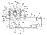
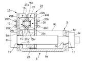
また、第3の実施形態では、上記金属製長方形枠9にも変更が加えられている。図25(a)(b)に示すように、上記金属製長方形枠9の電線受部12の上記左右側板12a,12bの上記溝13,13の下方近傍位置から、上記金属製長方形枠9の中央部より若干後方よりの範囲において、上記左側面板9cと上記右側面板9dから左右方向に水平載置板9e,9e’が設けられている。 Further, in the third embodiment, the metal rectangular frame 9 is also changed. As shown in FIGS. 25 (a) and 25 (b), the metal rectangular frame 9 is formed from a position near the lower side of the grooves 13 and 13 of the left and right side plates 12a and 12b of the electric wire receiving portion 12 of the metal rectangular frame 9. Horizontal mounting plates 9e and 9e'are provided in the left-right direction from the left side plate 9c and the right side plate 9d in a range slightly behind the central portion.

また、針電極15,27の形状は第1、第2の実施形態と同一であるが、電線Eのセンタリング機能があるので、ここで説明する(図25(a)(b)等)。上記針電極15は、左右方向に上針部15a〜15c、下針部15a’〜15c’が形成されているが、これらの上針部15a〜15cと下針部15a’〜15c’間は、後方に行くにつれて(後方側に向かう)末広がり状のテーパ部15d,15d,15d(上側、テーパ部の後側の先端縁は金属製の刃となっている)とテーパ部15d’,15d’,15d’(下側、テーパ部の後側の先端縁は金属製の刃となっている)が形成されている。また、針電極27は、左右方向に上針部27a,27b、下針部27a’,27b’が形成されているが、これらの上針部27a,27bと下針部27a’,27b’間は、前方に行くにつれて(前方側に向かう)末広がり状のテーパ部27c,27c(上側、テーパ部の前側の先端縁は金属製の刃となっている)とテーパ部27c’,27c’(下側、テーパ部の前側の先端縁は金属製の刃となっている)が形成されている。これらの上針部15a〜15c、下針部15a’〜15c’、及び上針部27a,27b、下針部27a’,27b’の上下高さは、同一水準位置に位置している。 Further, the shapes of the needle electrodes 15 and 27 are the same as those of the first and second embodiments, but since they have a centering function of the electric wire E, they will be described here (FIGS. 25 (a) and 25 (b) and the like). The upper needle portion 15a to 15c and the lower needle portion 15a'to 15c'are formed in the needle electrode 15 in the left-right direction. , 15d, 15d, 15d (upper side, the tip edge on the rear side of the tapered part is a metal blade) and the tapered parts 15d', 15d' , 15d'(the lower end edge of the rear side of the tapered portion is a metal blade) is formed. Further, in the needle electrode 27, upper needle portions 27a, 27b and lower needle portions 27a', 27b'are formed in the left-right direction, and between these upper needle portions 27a, 27b and lower needle portions 27a', 27b'. 27c, 27c (upper side, the tip edge on the front side of the tapered part is a metal blade) and the tapered parts 27c', 27c' (lower) as they go forward (toward the front side). The front edge of the tapered portion on the side is a metal blade). The vertical heights of the upper needle portions 15a to 15c, the lower needle portions 15a'to 15c', the upper needle portions 27a, 27b, and the lower needle portions 27a', 27b'are located at the same level.

上記水平載置板9e,9e’は水平方向の長方形状の板状体であり(図25,図26、図27参照)、左右は同一の大きさに構成されている。この水平載置板9e,9e’は、電線Eを電線把持部20,20及び可動電線把持部20,20にて挟持する場合、当該電線Eを上記水平載置板9e,9e’上に載置することにより、電線Eを電線把持具20,20及び可動電線把持具20,20によって挟持するまでの間、安定して載置保持することができるものである。具体的な作用については、以下の動作説明にて説明する。 The horizontal mounting plates 9e and 9e'are rectangular plate-like bodies in the horizontal direction (see FIGS. 25, 26 and 27), and the left and right sides are configured to have the same size. When the electric wire E is sandwiched between the electric wire gripping portions 20 and 20 and the movable electric wire gripping portions 20 and 20, the horizontal mounting plates 9e and 9e'mount the electric wire E on the horizontal mounting plates 9e and 9e'. By placing the electric wire E, the electric wire E can be stably placed and held until it is sandwiched by the electric wire gripping tools 20 and 20 and the movable electric wire gripping tools 20 and 20. The specific operation will be described in the following operation description.

第3の実施形態は上述のように構成されているので、以下、その作用について説明する。 Since the third embodiment is configured as described above, its operation will be described below.

第3の実施形態の電線止めクリップ1は、第1の実施形態と同様に、図11に示すように、上金具5上に固定され、電線受部12と可動電線受部24は図25(a)(b)に示すように離間しており、電線受部12側の電線把持部20,20と、可動電線受部24側の可動電線把持部20,20間には電線Eは存在せず、上記電線受部12側の電線把持部20,20は何れも直線L1,L1に対して、一点a,aから後方に傾斜しており、上記可動電線把持部24側の可動電線把持部20,20は何れも直線L1に対して、一点a,aから前方に傾斜しているものとする。 As shown in FIG. 11, the electric wire stopper clip 1 of the third embodiment is fixed on the upper metal fitting 5, and the electric wire receiving portion 12 and the movable electric wire receiving portion 24 are fixed to FIG. 25 (as shown in FIG. 11). a) As shown in (b), the electric wire E does not exist between the electric wire gripping portions 20 and 20 on the electric wire receiving portion 12 side and the movable electric wire gripping portions 20 and 20 on the movable electric wire receiving portion 24 side. However, the wire grip portions 20 and 20 on the wire receiving portion 12 side are all inclined rearward from one point a, a with respect to the straight lines L1 and L1, and the movable wire grip portion on the movable wire grip portion 24 side. It is assumed that both 20 and 20 are inclined forward from one point a, a with respect to the straight line L1.

次に、一定の径の電線Eを上記電線受部12と可動電線受部24間に上記電線止クリップ1の金属製長方形枠9の長手方向に直交する方向に配置する。このとき、上記水平載置板9e,9e’上に電線Eが載置される。この場合、図27(a)(b)に電線Eを二点鎖線で示すように、電線Eは上記水平載置板9e,9e’上に載置され、上記電線把持部20,20及び可動電線把持部20,20から少し下に位置することになる。 Next, an electric wire E having a constant diameter is arranged between the electric wire receiving portion 12 and the movable electric wire receiving portion 24 in a direction orthogonal to the longitudinal direction of the metal rectangular frame 9 of the electric wire stop clip 1. At this time, the electric wire E is placed on the horizontal mounting plates 9e and 9e'. In this case, as shown by the two-dot chain line in FIGS. 27 (a) and 27 (b), the electric wire E is mounted on the horizontal mounting plates 9e and 9e', and the electric wires gripping portions 20 and 20 and the movable wires E are movable. It will be located slightly below the wire grips 20 and 20.

その後、作業者は、上記ボルトBの頭に、六角レンチを嵌合し、当該六角レンチを右方向に回転させ、上記ボルトBを右螺子方向に回転する。すると、上記ボルトBが右螺子方向に回転するため、上記雌螺子部25を介して可動電線受部24が、電線受部12の方向に徐々に近接していく。このとき、水平載置板9e,9e’上に載置された電線E(図25(b)参照)を、針電極15,27の下側のテーパ部15d’,27c’が掬い上げながら、電線Eを水平載置板9e,9e’から徐々に上昇させる。このとき、上記可動電線受部24の可動電線把持部20,20の上記三角部20i,20iは、前方に傾斜しているので、下側の折曲部20j,20jが上記水平載置板9e,9e’上の電線Eの後方側側面Ebの下半部に当接し、上記折曲部20j,20jは電線Eに沿うように移動する。 After that, the operator fits a hexagon wrench on the head of the bolt B, rotates the hexagon wrench to the right, and rotates the bolt B to the right screw direction. Then, since the bolt B rotates in the right-hand screw direction, the movable electric wire receiving portion 24 gradually approaches the electric wire receiving portion 12 via the female screw portion 25. At this time, the electric wires E (see FIG. 25B) mounted on the horizontal mounting plates 9e and 9e'are scooped up by the tapered portions 15d' and 27c'on the lower side of the needle electrodes 15 and 27. The electric wire E is gradually raised from the horizontal mounting plates 9e and 9e'. At this time, since the triangular portions 20i and 20i of the movable electric wire gripping portions 20 and 20 of the movable electric wire receiving portion 24 are inclined forward, the lower bent portions 20j and 20j are the horizontal mounting plates 9e. , 9e'Abuts on the lower half of the rear side surface Eb of the electric wire E, and the bent portions 20j and 20j move along the electric wire E.

また、上記操作者が上記ボルトBを回転すると、電線受部12側の電線把持部20,20の上記三角部20i,20iは、後方に傾斜しているので、下側の折曲部20j,20jが上記水平載置部9e,9e’上の電線Eの前方側側面Eaの下半部に当接し、上記屈曲部20j,20jは電線Eに沿うように移動する。 Further, when the operator rotates the bolt B, the triangular portions 20i and 20i of the electric wire gripping portions 20 and 20 on the electric wire receiving portion 12 side are inclined rearward, so that the lower bent portion 20j, The 20j comes into contact with the lower half of the front side surface Ea of the electric wire E on the horizontal mounting portions 9e and 9e', and the bent portions 20j and 20j move along the electric wire E.

その後、さらに操作者が上記ボルトBを右螺子方向に回転すると、電線Eは、前後から針電極15,27の下側のテーパ部15d’,27c’が電線Eを掬い上げながら、電線Eを徐々に水平載置板9e,9e’から徐々に上昇させ、最終的に、針電極15の上側のテーパ部15d(左右方向の3か所)と下側のテーパ部15d’(左右方向の3か所)、及び、針電極27の上側のテーパ部27c(左右方向の2か所)と下側のテーパ部27c’(左右方向の2か所)により、針電極15と針電極27の中心位置に上昇させられ、針電極15及び針電極27により電線Eのセンタリングが行われる(図26(b)参照)。即ち、前後のテーパ部15d,15d’及び27c,27c’の中心部に電線Eが位置することになる。尚、この時点で、針電極15と27のテーパ部の先端縁は、電線Eの導体Ecに接触する。 After that, when the operator further rotates the bolt B in the right-hand screw direction, the electric wire E draws the electric wire E while the tapered portions 15d'and 27c'on the lower side of the needle electrodes 15 and 27 scoop up the electric wire E from the front and back. Gradually raise from the horizontal mounting plates 9e and 9e', and finally, the upper tapered portion 15d (three places in the left-right direction) and the lower tapered portion 15d' (three in the left-right direction) of the needle electrode 15. The center of the needle electrode 15 and the needle electrode 27 due to the upper tapered portion 27c (two locations in the left-right direction) and the lower tapered portion 27c'(two locations in the left-right direction) of the needle electrode 27. It is raised to the position, and the needle electrode 15 and the needle electrode 27 center the electric wire E (see FIG. 26 (b)). That is, the electric wire E is located at the center of the front and rear tapered portions 15d, 15d'and 27c, 27c'. At this point, the tip edges of the tapered portions of the needle electrodes 15 and 27 come into contact with the conductor Ec of the electric wire E.

そして、最終的には図26(a)(b)、図27(a)(b)に示すように、上記電線受部12側の左右の電線把持部20,20の三角部20i,20iの連結部20kの中心が、電線Eの前方側側面Eaの軸方向の中心線L4に位置し、左右の上線部20b,20bと下線部20c,20cに沿って電線Eが位置するように、即ち、左右の上線部20b,20bと下線部20c,20cの間隔の中央部が、電線Eの前方側側面Eaの長手方向の略中央位置に位置するように当該電線Eが配置される。 Finally, as shown in FIGS. 26 (a) and 26 (b) and 27 (a) and 27 (b), the triangular portions 20i and 20i of the left and right wire gripping portions 20 and 20 on the wire receiving portion 12 side. The center of the connecting portion 20k is located at the axial center line L4 of the front side surface Ea of the electric wire E, and the electric wire E is located along the left and right overlined portions 20b and 20b and the underlined portions 20c and 20c, that is. The electric wire E is arranged so that the central portion of the distance between the left and right overlined portions 20b and 20b and the underlined portions 20c and 20c is located at a substantially central position in the longitudinal direction of the front side surface Ea of the electric wire E.

同時に、図27(b)に示すように、上記電線Eは、上記可動電線受部24側の左右の可動電線把持部20,20の三角部20i,20iの連結部20kの中心が、電線Eの後方側側面Ebの軸方向の中心線L4に位置し、左右の上線部20b,20bと下線部20c,20cに沿って電線Eが位置するように、即ち、左右の上線部20b,20bと下線部20c,20cの間隔の中央部が、電線Eの後方側側面Ebの長手方向の略中央位置に対応して位置するように当該電線Eが配置される。 At the same time, as shown in FIG. 27B, in the electric wire E, the center of the connecting portion 20k of the triangular portions 20i and 20i of the left and right movable electric wire gripping portions 20 and 20 on the movable electric wire receiving portion 24 side is the electric wire E. The electric wires E are located along the left and right overlined portions 20b and 20b and the underlined portions 20c and 20c, that is, the left and right overlined portions 20b and 20b. The electric wire E is arranged so that the central portion of the interval between the underlined portions 20c and 20c is located substantially at the center of the rear side surface Eb of the electric wire E in the longitudinal direction.

そして、電線把持部20,20の先端の左右の上下の湾曲部20m,20mに電線Eの前方側側面Eaが接触し、上記前方側側面Ea,Eaにて電線把持部20,20の接触部23,23の各後方側の附勢力に抗して前方側に押され、図26(a)に示すように、電線把持部20,20の左右の上記接触部23,23(左右の各上線部20b,下線部20c)は、上記電線Eの前方側側面Eaに平行な状態まで押され、当該平行状態で、後方側の附勢力を電線Eの前方側側面Eaに及ぼした状態で上記電線Eの前方側側面Eaに強く接触(密着)した状態となる。 Then, the front side surface Ea of the electric wire E comes into contact with the left and right upper and lower curved portions 20 m and 20 m of the tips of the electric wire grip portions 20 and 20, and the contact portions of the electric wire grip portions 20 and 20 are brought into contact with the front side surfaces Ea and Ea. It is pushed forward against the urging force on each of the rear sides of 23 and 23, and as shown in FIG. The portion 20b and the underlined portion 20c) are pushed to a state parallel to the front side surface Ea of the electric wire E, and in the parallel state, the rear side urging force is applied to the front side surface Ea of the electric wire E. It is in a state of being strongly contacted (closely attached) to the front side surface Ea of E.

このとき上記電線把持部20,20の両端の三角部20i,20iの湾曲部20n,20nに案内されて、電線Eの前方側側面Eaが入り込み(図26(a)、図24(a)参照)、電線Eの周方向の円弧が湾曲部20nに沿って位置し、これにより電線Eの上記中心線L4が上記電線把持部20,20の上線部20b、下線部20cの中間部に位置し、電線把持部20,20に対して電線Eがずれないように構成される(図26(a)、図35(a)参照)。 At this time, the front side surface Ea of the electric wire E is guided by the curved portions 20n and 20n of the triangular portions 20i and 20i at both ends of the electric wire grip portions 20 and 20 (see FIGS. 26 (a) and 24 (a)). ), The circumferential arc of the electric wire E is located along the curved portion 20n, whereby the center line L4 of the electric wire E is located at the intermediate portion between the upper line portion 20b and the underline portion 20c of the electric wire grip portions 20 and 20. , The electric wire E is configured so as not to be displaced with respect to the electric wire gripping portions 20 and 20 (see FIGS. 26 (a) and 35 (a)).

同様に、可動電線把持部20,20の両端の三角部20i,20iの湾曲部20n,20nに案内されて、電線Eの後方側側縁Ebが入り込み(図26(a)、図24(a)参照)、電線Eの周方向の円弧が湾曲部20nに沿って位置し、これにより電線Eの上記中心線L4が上記可動電線把持部20,20の上線部20b、下線部20cの中間部に位置し、上記可動電線把持部20,20に対して電線Eがずれないように構成されている(図26(a)、図35(a)参照)。 Similarly, the rear side edge Eb of the electric wire E is guided by the curved portions 20n and 20n of the triangular portions 20i and 20i at both ends of the movable electric wire grip portions 20 and 20 (FIGS. 26 (a) and 24 (a). ), The circumferential arc of the electric wire E is located along the curved portion 20n, whereby the center line L4 of the electric wire E is the intermediate portion between the upper line portion 20b and the underline portion 20c of the movable electric wire grip portions 20 and 20. It is configured so that the electric wire E does not shift with respect to the movable electric wire gripping portions 20 and 20 (see FIGS. 26 (a) and 35 (a)).

そして、上記ボルトBの右回りの回転により、可動電線受部24側の左右の可動電線把持部20,20は(特に、両先端の三角部20i,20iは)、上記電線Eの後方側側面Eb(可動電線受部24側の左右側面)に各々当接し、同様に上記電線Eの後方側側面Ebを前方に押圧していく。このとき、上記電線把持部20,20の上記三角部20i,20iは、各々電線Eの前方側側面Ea側(後方側)に屈曲し、かつ、上記可動電線把持部20,20の上記三角部20i,20iの上記折曲部20j,20jは、各々電線Eの後方側側面Eb側(前方側)の軸方向に沿って屈曲し、かつ、上記連結部20kは電線Eの周方向に沿って湾曲しているので、左側において、上下の折曲部20j,20j及び連結部20kにより電線Eの前方側側面Eaと後方側側面Ebを包み込む状態となり、右側においても同様に、上下の折曲部20j,20j及び連結部20kにより電線Eの前方側側面Eaと後方側側面Ebを包み込む状態となり(図26(a)参照)、電線把持部20,20及び可動電線把持部20,20により電線Eを挟持していく過程において、電線Eの電線把持部20,20及び可動電線把持部20,20からの外れを防止して、安定して電線Eを挟持していくことができる。 Then, due to the clockwise rotation of the bolt B, the left and right movable electric wire gripping portions 20 and 20 on the movable electric wire receiving portion 24 side (particularly, the triangular portions 20i and 20i at both ends) are placed on the rear side surface of the electric wire E. Each of them abuts on Eb (left and right side surfaces on the movable electric wire receiving portion 24 side), and similarly presses the rear side side surface Eb of the electric wire E forward. At this time, the triangular portions 20i and 20i of the electric wire grip portions 20 and 20 are bent toward the front side side surface Ea side (rear side) of the electric wire E, respectively, and the triangular portions of the movable electric wire grip portions 20 and 20 are formed. The bent portions 20j and 20j of the 20i and 20i are bent along the axial direction of the rear side side surface Eb side (front side) of the electric wire E, respectively, and the connecting portion 20k is along the circumferential direction of the electric wire E. Since it is curved, the upper and lower bent portions 20j and 20j and the connecting portion 20k wrap the front side side surface Ea and the rear side side surface Eb of the electric wire E on the left side, and similarly on the right side, the upper and lower bent portions. The front side surface Ea and the rear side side surface Eb of the electric wire E are wrapped by the 20j, 20j and the connecting portion 20k (see FIG. In the process of sandwiching the electric wire E, the electric wire E can be stably sandwiched by preventing the electric wire E from coming off from the electric wire gripping portions 20 and 20 and the movable electric wire gripping portions 20 and 20.

上記可動電線受部24側の上記左右の三角部20i,20iにて上記電線Eを前方に押していくと、上記電線Eを前方側に押していくと共に、上記電線受部12の左右の電線把持部20,20の後方向きの附勢力に抗して電線Eを前方に押していく状況になり、この状況になると、上記可動電線把持部20,20においても、これらの可動電線把持部20,20の前方向きの附勢力に抗して上記電線Eを前方に押していくことになり、上記電線受部12側の左右の電線把持部20,20が上記電線Eに平行になった状態において、略同時期に、可動電線受部24側の左右の可動電線把持部20,20が、上記電線Eの後方側側面Eb(可動電線受部24側の側面)に平行な状態となり、図26(a)に示すように、左右の可動電線把持部20,20の上記左右の接触部23,23(左右の上線部20b,下線部20c)は、上記電線Eの後方側側面Ebに平行な状態まで押され、当該平行状態で、前方側の附勢力を電線Eの後方側側面Ebに及ぼした状態で上記電線Eの側面に強く接触(密着)した状態となる。 When the electric wire E is pushed forward by the left and right triangular portions 20i and 20i on the movable electric wire receiving portion 24 side, the electric wire E is pushed forward and the left and right electric wire grip portions of the electric wire receiving portion 12 are pushed. The electric wire E is pushed forward against the backward urging force of 20 and 20, and in this situation, the movable electric wire gripping portions 20 and 20 also have the movable electric wire gripping portions 20 and 20. The electric wire E is pushed forward against the forward urging force, and in a state where the left and right electric wire gripping portions 20 and 20 on the electric wire receiving portion 12 side are parallel to the electric wire E, the same is substantially the same. At this time, the left and right movable electric wire gripping portions 20 and 20 on the movable electric wire receiving portion 24 side are in a state parallel to the rear side side surface Eb (the side surface on the movable electric wire receiving portion 24 side) of the electric wire E, and FIG. As shown in the above, the left and right contact portions 23, 23 (left and right upper line portions 20b, underline portion 20c) of the left and right movable electric wire grip portions 20 and 20 are pushed to a state parallel to the rear side side surface Eb of the electric wire E. Then, in the parallel state, the urging force on the front side is applied to the rear side surface Eb of the electric wire E, and the side surface of the electric wire E is strongly contacted (adhered).

このとき、電線Eは電線受部12、可動電線受部24の内側の針電極15,27によりセンタリングされているが(図26(b)参照)、電線受部12、可動電線受部24より外側に出た左右方向の電線Eが例えば上下方向に移動したとしても(電線受部12、可動電線受部24の左又は右の一方の電線Eが水平であっても、電線受部12、可動電線受部24の右又は左の他方の電線Eが上下方向に移動したときを含む)、上記電線Eの前方側側面Ea及び後方側側面Ebには上下の折曲部20j,20jが前後方向から包み込むように位置しているので、電線把持部20及び可動電線把持部20は電線Eの上下方向の動きに追従して、接触部23,23を含めて弾性的に上下方向に動くことができ、電線Eから外れることはない。この機能は、第1の実施形態(U字状部20a)より、三角部20iの方が電線Eへの引っ掛かりが強いので、第1の実施形態より強化されている。 At this time, the electric wire E is centered by the needle electrodes 15 and 27 inside the electric wire receiving portion 12 and the movable electric wire receiving portion 24 (see FIG. 26B), but from the electric wire receiving portion 12 and the movable electric wire receiving portion 24. Even if the electric wire E in the left-right direction that goes out to the outside moves, for example, in the vertical direction (even if one of the left or right electric wires E of the electric wire receiving portion 12 and the movable electric wire receiving portion 24 is horizontal, the electric wire receiving portion 12, (Including when the other electric wire E on the right or left side of the movable electric wire receiving portion 24 moves in the vertical direction), the upper and lower bent portions 20j and 20j are front and rear on the front side side surface Ea and the rear side side surface Eb of the electric wire E. Since it is positioned so as to wrap from the direction, the electric wire gripping portion 20 and the movable electric wire gripping portion 20 follow the vertical movement of the electric wire E and elastically move in the vertical direction including the contact portions 23 and 23. Can be done and will not come off from the wire E. This function is enhanced as compared with the first embodiment because the triangular portion 20i is more likely to be caught by the electric wire E than the first embodiment (U-shaped portion 20a).

また、電線把持部20の折曲部20jと、可動電線把持部20の折曲部20j同士は、図26(a)に示すように、左右方向に若干ずれた状態で近接部c’にて近接又は接触するので、電線Eの直径が小の場合であっても支障なく電線把持部20,20及び可動電線把持部20,20にて電線Eを把持し得る。また、湾曲部20nが電線Eの周方向の円弧部に接触することにより、先端の上記三角部20iに接触する電線Eに対する曲げ応力の集中を緩和し、電線の破損を防止することができる。 Further, as shown in FIG. 26A, the bent portion 20j of the electric wire gripping portion 20 and the bent portion 20j of the movable electric wire gripping portion 20 are slightly displaced in the left-right direction at the proximity portion c'. Since they are close to each other or come into contact with each other, the electric wire E can be gripped by the electric wire gripping portions 20 and 20 and the movable electric wire gripping portions 20 and 20 without any problem even when the diameter of the electric wire E is small. Further, when the curved portion 20n comes into contact with the arc portion in the circumferential direction of the electric wire E, the concentration of bending stress on the electric wire E in contact with the triangular portion 20i at the tip can be alleviated, and the electric wire can be prevented from being damaged.

上記作業者は、上記六角レンチを右方向に回転し、電線受部12の左右の電線把持部20,20(接触部23)、及び、可動電線受部24の左右の可動電線把持部20,20(接触部23)が図26(a)に示すように電線Eの前方側側面Ea、後方側側面Ebに各々平行に接し、上記電線受部12側の左右の電線把持部20,20と、上記可動電線受部24側の左右の可動電線把持部20,20が、電線Eの前方側と後方側の両側面Ea,Ebに平行となり、上記電線Eの前方側と後方側の両側面Ea,Ebが上記左右の電線把持部20,20及び可動電線把持部20,20によって挟み込むように把持された時点で、上記六角レンチの回転を停止する。 The operator rotates the hexagonal wrench to the right, and the left and right electric wire gripping portions 20 and 20 (contact portion 23) of the electric wire receiving portion 12 and the left and right movable electric wire gripping portions 20 of the movable electric wire receiving portion 24, 20 (contact portion 23) is in parallel with the front side side surface Ea and the rear side side surface Eb of the electric wire E as shown in FIG. The left and right movable electric wire gripping portions 20 and 20 on the movable electric wire receiving portion 24 side are parallel to both front and rear side surfaces Ea and Eb of the electric wire E, and both front and rear side surfaces of the electric wire E. When Ea and Eb are gripped so as to be sandwiched between the left and right electric wire grip portions 20 and 20 and the movable electric wire grip portions 20 and 20, the rotation of the hexagonal wrench is stopped.

この状態において、左の上記電線Eは、電線受部12側の左の弾性線材からなる電線把持部20の後方向きの附勢力と、可動電線受部24側の左の弾性線材からなる可動電線把持部20の前方向きの附勢力によって、上記各接触部23,23が電線Eに密着し(図26(a)参照)、上記各接触部23,23の所定長さに亘って、軸方向に、該電線Eの前方側側面Ea及び後方側側面Ebから強く挟持された状態となる。 In this state, the left electric wire E is a movable electric wire composed of a rearward urging force of the electric wire grip portion 20 made of the left elastic wire material on the electric wire receiving portion 12 side and the left elastic wire material on the movable electric wire receiving portion 24 side. Due to the forward urging force of the grip portion 20, the contact portions 23, 23 are brought into close contact with the electric wire E (see FIG. 26 (a)), and the contact portions 23, 23 are in axial direction over a predetermined length. In addition, the electric wire E is strongly sandwiched from the front side surface Ea and the rear side surface Eb.

同時に、右の電線Eも、上記電線受部12側の右の弾性線材からなる電線把持部20の後方向きの附勢力と、可動電線受部24側の右の弾性線材からなる可動電線把持部20の前方向きの附勢力によって、上記各接触部23,23が電線Eに密着し、上記各接触部23,23の所定長さに亘って、軸方向に、該電線Eの前方側側面Ea及び後方側側面Ebから強く挟持された状態となる。 At the same time, the right electric wire E also has a rearward urging force of the electric wire grip portion 20 made of the right elastic wire material on the electric wire receiving portion 12 side and a movable electric wire grip portion made of the right elastic wire material on the movable electric wire receiving portion 24 side. The forward urging force of 20 causes the contact portions 23, 23 to come into close contact with the electric wire E, and the front side surface Ea of the electric wire E axially extends over the predetermined lengths of the contact portions 23, 23. And it is in a state of being strongly sandwiched from the rear side surface Eb.

また、このとき、電線Eは、図26(b)、図21(a)に示すように、その前方側側面Eaは、電線把持部20,20の上下線部20b,20cに当接して上記溝13,13内において確実に支持され、その後方側側面Ebは、可動電線把持部20,20の上下線部20b,20cに当接して上記溝26,26内において確実に支持され、ずれることはない。また、針電極15,27を確実に導体に接触させることができる(図26(b)、図21(a)参照)。 Further, at this time, as shown in FIGS. 26 (b) and 21 (a), the electric wire E is in contact with the vertical line portions 20b and 20c of the electric wire grip portions 20 and 20 and the front side surface Ea is in contact with the electric wire grip portions 20 and 20. It is securely supported in the grooves 13 and 13, and its rear side surface Eb abuts on the vertical wire portions 20b and 20c of the movable electric wire gripping portions 20 and 20 and is surely supported and displaced in the grooves 26 and 26. There is no. Further, the needle electrodes 15 and 27 can be surely brought into contact with the conductor (see FIGS. 26 (b) and 21 (a)).

尚、電線Eの径が大の場合であっても、図21(b)、図21(c)に示すように、第2の実施形態と同様に、電線Eを確実に支持することができるし、針電極15,27の電線Eへの入り込み量を制御でき、電線の径が変化しても、針電極15,27の電線Eへの入り込み量を一定とすることができる(図21(a)〜(c)参照)。この点は、第3の実施形態でも同様である。 Even when the diameter of the electric wire E is large, as shown in FIGS. 21 (b) and 21 (c), the electric wire E can be reliably supported as in the second embodiment. However, the amount of the needle electrodes 15 and 27 entering the electric wire E can be controlled, and the amount of the needle electrodes 15 and 27 entering the electric wire E can be kept constant even if the diameter of the electric wire changes (FIG. 21 (FIG. 21). a)-(c)). This point is the same in the third embodiment.

そして、上記電線Eの径に拘わらず、電線Eの前方側側面Eaと後方側側面Ebは、上記三角部20i,20iの電線Eの側面に沿った湾曲部20n,20nに沿って支持されるので、三角部20i,20iと電線Eの接触部に応力が集中することはない。 Then, regardless of the diameter of the electric wire E, the front side surface Ea and the rear side side surface Eb of the electric wire E are supported along the curved portions 20n and 20n along the side surface of the electric wire E of the triangular portions 20i and 20i. Therefore, stress does not concentrate on the contact portions between the triangular portions 20i and 20i and the electric wire E.

また、かかる状態において、図26(b)に示すように、電線止クリップ1の電線受部12側の針電極15の上下針部15a〜15c,15a’〜15c’及び可動電線受部24側の針電極27の上下針部27a,27b、27a’,27b’は各々上記電線Eの被覆を破って内部の導体Ecに接触し、電線止クリップ1との導通状態を実現し得る。また上記針電極15,27の左右の電線Eの所定長に亘り電線把持部20,20及び可動電線把持部20,20にて電線Eを把持し得るので(図26(a)参照)、針電極近傍での電線Eの応力集中を防止し得て、電線止クリップ1の放電機能が害されることがない。 Further, in such a state, as shown in FIG. 26B, the upper and lower needle portions 15a to 15c, 15a'to 15c' of the needle electrode 15 on the wire receiving portion 12 side of the wire stop clip 1 and the movable wire receiving portion 24 side. The upper and lower needle portions 27a, 27b, 27a', 27b'of the needle electrode 27 of the above can break the coating of the electric wire E and come into contact with the inner conductor Ec, respectively, to realize a conductive state with the electric wire stop clip 1. Further, since the electric wire E can be gripped by the electric wire gripping portions 20 and 20 and the movable electric wire gripping portions 20 and 20 over the predetermined lengths of the left and right electric wires E of the needle electrodes 15 and 27 (see FIG. 26A), the needle. The stress concentration of the electric wire E in the vicinity of the electrode can be prevented, and the discharge function of the electric wire stop clip 1 is not impaired.

また、風により、上記電線Eは図13(b)に示すように、その中央部Mを最も大きな振幅を以って前後方向(矢印F,F’方向)に振動する。このとき、電線Eの電線止クリップ1の左右両側において、電線Eの前方側と後方側の円弧状の両側面Ea,Ebは、電線把持部20,20と、可動電線把持部20,20の接触部23,23によって、長手方向の所定範囲に亘って挟持されているので(図26(a)参照)、第1、2の実施形態と同様に、電線Eの上記接触部23,23が接触している挟持部(電線Eの軸方向の所定長さ)における特定の部位に応力が集中することがなく、従って、振動による電線Eの劣化、或いは断線等の事故を極めて効果的に防止することができる(例えば図26(a)にて、電線が矢印F(F’)方向に振動したとき、電線把持部20(可動電線把持部20)は矢印F(F’)方向に変形し得るが、可動電線把持部20(電線把持部20)も前方(後方)に附勢されているので、F(F’)方向に電線Eの変形に追従し得して変形し得る。 Further, as shown in FIG. 13B, the electric wire E vibrates in the front-rear direction (arrows F, F'direction) with the largest amplitude in the central portion M due to the wind. At this time, on the left and right sides of the electric wire stop clip 1 of the electric wire E, the arc-shaped both side surfaces Ea and Eb on the front side and the rear side of the electric wire E are the electric wire gripping portions 20 and 20 and the movable electric wire gripping portions 20 and 20. Since the contact portions 23, 23 are sandwiched over a predetermined range in the longitudinal direction (see FIG. 26A), the contact portions 23, 23 of the electric wire E are similarly connected to the first and second embodiments. Stress does not concentrate on a specific part of the in contacting holding portion (predetermined length in the axial direction of the electric wire E), and therefore, accidents such as deterioration or disconnection of the electric wire E due to vibration are extremely effectively prevented. (For example, in FIG. 26A, when the electric wire vibrates in the direction of the arrow F (F'), the electric wire grip portion 20 (movable electric wire grip portion 20) is deformed in the direction of the arrow F (F'). However, since the movable electric wire grip portion 20 (electric wire grip portion 20) is also biased forward (rear), it can follow the deformation of the electric wire E in the F (F') direction and can be deformed.

特に、電線Eは前方側側面Eaと後方側側面Ebとが電線把持部及び可動電線把持部20,20によって所定長さに亘って対向するバネ力によって強く挟持された状態となり、電線Eが振動しても、所定長さの電線把持部も電線と共に弾性的に振動するので、電線Eの挟持箇所の特定部位への応力集中を分散することができる。また、電線把持部20,20、可動電線把持部20,20の基端が電線を確実に支持することも加わり、電線の動きによる応力集中が、針電極近傍で起きることがなく、放電機能にも影響を与えない。 In particular, the electric wire E is in a state where the front side surface Ea and the rear side side surface Eb are strongly sandwiched by the electric wire gripping portions and the movable electric wire gripping portions 20 and 20 by the spring force facing each other over a predetermined length, and the electric wire E vibrates. Even so, since the electric wire gripping portion having a predetermined length also elastically vibrates together with the electric wire, the stress concentration on the specific portion of the sandwiched portion of the electric wire E can be dispersed. In addition, the base ends of the electric wire grips 20 and 20 and the movable electric wire grips 20 and 20 reliably support the electric wire, so that stress concentration due to the movement of the electric wire does not occur near the needle electrode, and the discharge function is provided. Does not affect.

また、電線把持部20と可動電線把持部20は、縦方向(上下方向)の上線部20aと下線部20bによって電線の円弧状の前方側側面Eaと後方側側面Ebとを挟持する構成であるから、電線の前後方向の振動に追従し易くなり、電線に対する曲げ応力の集中を効果的に分散し得る。 Further, the electric wire gripping portion 20 and the movable electric wire gripping portion 20 are configured to sandwich the arc-shaped front side surface Ea and the rear side side surface Eb of the electric wire by the upper line portion 20a and the underline portion 20b in the vertical direction (vertical direction). Therefore, it becomes easy to follow the vibration in the front-rear direction of the electric wire, and the concentration of bending stress on the electric wire can be effectively dispersed.

しかも、電線の前方側側面Eaを2本の上線部20bと下線部20cによって上下方向に間隔を開けた状態で保持し、電線の円弧状の後方側側面Ebを2本の上線部20bと下線部20cにて上下方向に間隔を開けた状態で電線の円弧状の側面を保持するものであるから、電線の前後方向の動き(図10矢印F,F’方向)だけでなく、例えば上下方向の動き(図10矢印Q,Q’方向)にも追従することができ、電線の多方面の動きに追従し得て、電線に対する応力の集中を効果的に分散し得る。 Moreover, the front side surface Ea of the electric wire is held by the two upper line portions 20b and the underline portion 20c in a vertically spaced state, and the arcuate rear side side surface Eb of the electric wire is underlined with the two upper line portions 20b. Since the arcuate side surface of the electric wire is held by the portion 20c with a space in the vertical direction, not only the movement of the electric wire in the front-rear direction (in the directions of arrows F and F'in FIG. 10) but also in the vertical direction, for example. It is possible to follow the movement of the electric wire (in the directions of arrows Q and Q'in FIG. 10), to follow the movement of the electric wire in various directions, and to effectively disperse the concentration of stress on the electric wire.

特に、第3の実施形態では、上記第2の実施形態と同様に、上記電線Eの前方側側面Ea及び後方側側面Ebには上下の折曲部20j,20jが前後方向から包み込むように位置しており、折曲部20j,20jが電線Eの前後に引っ掛かっているので、電線把持部20及び可動電線把持部20は電線Eの上下方向の動きに追従して、接触部23,23を含めて弾性的に上下方向に動くことができ、電線Eから外れることはない。 In particular, in the third embodiment, similarly to the second embodiment, the upper and lower bent portions 20j and 20j are positioned so as to wrap the front side side surface Ea and the rear side side surface Eb of the electric wire E from the front-rear direction. Since the bent portions 20j and 20j are hooked on the front and back of the electric wire E, the electric wire gripping portion 20 and the movable electric wire gripping portion 20 follow the vertical movement of the electric wire E to form the contact portions 23 and 23. It can move elastically in the vertical direction including it, and does not come off from the electric wire E.

上述のように、第3の実施形態においても、第1,2の実施形態と同様に、電線止クリップ1の左右両側において電線Eを確実に挟持することができ、これにより電線把持部20と可動電線把持部20が電線Eに密着して電線Eの振動に追従し得るため、電線Eへの曲げ応力を均等に分散し、素線間摩耗の軽減効果を高めることができる。 As described above, also in the third embodiment, as in the first and second embodiments, the electric wire E can be reliably sandwiched on both the left and right sides of the electric wire stop clip 1, whereby the electric wire gripping portion 20 and the electric wire gripping portion 20 can be sandwiched. Since the movable electric wire grip portion 20 can adhere to the electric wire E and follow the vibration of the electric wire E, the bending stress on the electric wire E can be evenly distributed and the effect of reducing the wear between the wires can be enhanced.

第3の実施形態においては、電線把持部は例えば直径約3mmの弾性線材(spring wire)であり、第1の実施形態と同様に、耐食性に優れたステンレス(例えばSUS304WPB等)を使用し、一端を三角状に曲げ加工し、例えば平行な幅9mmの直線部(接触部23)を有し、他端はクランク状に曲げ加工した一対の端部20b’,20c’が形成されている(1本の線材を中央から折り返し上下対称に成形する)。 In the third embodiment, the electric wire grip portion is, for example, an elastic wire having a diameter of about 3 mm (spring wire), and as in the first embodiment, stainless steel having excellent corrosion resistance (for example, SUS304WPB) is used, and one end thereof is used. Has a parallel straight portion (contact portion 23) having a width of 9 mm, and a pair of end portions 20b'and 20c' that are bent in a crank shape are formed at the other end (1). The wire of the book is folded back from the center and molded vertically symmetrically).

(第4の実施形態)(図28〜図31参照)
次に、第4の実施形態について説明する。
尚、上記第1の実施形態と同一部分については同一符号を付し、それらの説明は省略する。
(Fourth Embodiment) (See FIGS. 28 to 31)
Next, a fourth embodiment will be described.
The same parts as those in the first embodiment are designated by the same reference numerals, and the description thereof will be omitted.

図28(a)〜(c)に示すように、電線把持部20は、金属製の弾性線材から構成されている点、及び、端部20b’,20c’側の形状、即ち、溝係合部21,21、挿通部22,22の形状は第1の実施形態の電線把持部20と同じであるが、折り返し部の形状が、第3の実施形態では三角部20i(図24参照)であるのに対し、上記三角部20iの上線部20b側の折曲部20jは第3の実施形態と同様に、上線部20bの他端から上線部20bと下線部20cの間隔を広げる方向に一旦拡幅するが、下線部20c側の折曲部20jを形成することなく、そのまま下線部20cを直線的に延長して直線部20qを形成し、該直線部20qが連結部20kに接続するように構成する。このように構成した折り返し部をR形部20pという。 As shown in FIGS. 28 (a) to 28 (c), the wire grip portion 20 has a point formed of an elastic wire made of metal and a shape on the end portions 20b'and 20c', that is, groove engagement. The shapes of the portions 21 and 21 and the insertion portions 22 and 22 are the same as those of the wire gripping portion 20 of the first embodiment, but the shape of the folded portion is the triangular portion 20i (see FIG. 24) in the third embodiment. On the other hand, the bent portion 20j on the upper line portion 20b side of the triangular portion 20i is once in the direction of widening the distance between the upper line portion 20b and the underline portion 20c from the other end of the upper line portion 20b, as in the third embodiment. Although the width is widened, the underlined portion 20c is linearly extended to form the straight portion 20q without forming the bent portion 20j on the underlined portion 20c side, so that the straight portion 20q is connected to the connecting portion 20k. Constitute. The folded portion configured in this way is referred to as an R-shaped portion 20p.

より詳細に説明すると、上の上記折曲部20jは、図28(b)の平面図をみると、上線部20b(上線部20bと下線部20cとの距離)から拡幅しているのみならず、上記溝係合部21,21とは逆方向(電線Eの方向)に屈曲することにより、上線部20bには、電線Eの幅方向の周面に沿う湾曲部20mが形成され、さらに上記連結部20kは、図28(a)に示すように、電線Eの円周方向の面に沿うように湾曲部20nが形成されている。これにより、上記R形部20pの上線部20b側の湾曲部20mは、図30(a)に示すように、電線Eの前方側側面Eaの軸方向の周面に沿うと共に、電線Eの後方側側面Ebの軸方向に沿う周面に沿い、図28(a)に示すように、電線Eの円周方向に沿う湾曲部20nが形成されている。尚、図28(a)(c)に示すように、上記連結部20kの上記湾曲部20nの下側の湾曲部を下側湾曲部20rという(図35(b)参照)。 More specifically, the above-mentioned bent portion 20j is not only widened from the overlined portion 20b (distance between the overlined portion 20b and the underlined portion 20c) in the plan view of FIG. 28 (b). By bending in the direction opposite to the groove engaging portions 21 and 21 (in the direction of the electric wire E), the overlined portion 20b is formed with a curved portion 20m along the peripheral surface in the width direction of the electric wire E, and further described above. As shown in FIG. 28A, the connecting portion 20k has a curved portion 20n formed along the surface of the electric wire E in the circumferential direction. As a result, as shown in FIG. 30A, the curved portion 20m on the upper line portion 20b side of the R-shaped portion 20p is along the circumferential surface of the front side surface Ea of the electric wire E in the axial direction and is behind the electric wire E. As shown in FIG. 28A, a curved portion 20n along the circumferential direction of the electric wire E is formed along the peripheral surface of the side side surface Eb along the axial direction. As shown in FIGS. 28 (a) and 28 (c), the lower curved portion of the connecting portion 20k and the curved portion 20n is referred to as a lower curved portion 20r (see FIG. 35 (b)).

また、第4の実施形態の電線把持部20の形状は、左側の電線把持部20と右側の可動電線把持部20が同一形状、右側の電線把持部20と左側の可動電線把持部20が同一形状となり、左右の電線把持部20,20(可動電線把持部20,20も同じ)は、左右対称形状となる。 Further, in the shape of the electric wire grip portion 20 of the fourth embodiment, the electric wire grip portion 20 on the left side and the movable electric wire grip portion 20 on the right side have the same shape, and the electric wire grip portion 20 on the right side and the movable electric wire grip portion 20 on the left side have the same shape. The left and right electric wire grips 20 and 20 (same for the movable electric wire grips 20 and 20) have a symmetrical shape.

また、図28(b)に示すように、上下線部20b,20cは、左右水平線L1,L1に対して後方傾斜角θ又は前方傾斜角θ(例えばθ=約10度)として後方又は前方に傾斜している点は第1の実施形態の電線把持部20と同じである(図29(a)参照)。 Further, as shown in FIG. 28B, the vertical line portions 20b and 20c are rearward or forward with respect to the left and right horizontal lines L1 and L1 with a rearward inclination angle θ or a forward inclination angle θ (for example, θ = about 10 degrees). The point of inclination is the same as that of the electric wire grip portion 20 of the first embodiment (see FIG. 29 (a)).

そして、図29、図30に示すように、電線受部12に、電線把持部20,20の基端部(溝係合部21、挿通部22)が第1の実施形態と同様に固定され、図29(a)(b)に示すように、上記上下線部20b,20c及び上記R部20p,20pが上記電線受部12の左右に水平になるように固定され、4本全体の折曲部20jが上側、直線部20qが下側になるように電線受部12に固定された状態で、左右の上下線部20b,20cは、左右水平線L1,L1に対して後方に傾斜角θ(例えばθ=約10度)に傾斜している(図29(a)参照)。 Then, as shown in FIGS. 29 and 30, the base end portions (groove engaging portion 21, insertion portion 22) of the electric wire gripping portions 20 and 20 are fixed to the electric wire receiving portion 12 in the same manner as in the first embodiment. As shown in FIGS. 29 (a) and 29 (b), the upper and lower wire portions 20b and 20c and the R portions 20p and 20p are fixed so as to be horizontal to the left and right of the electric wire receiving portion 12, and the entire four wires are folded. With the curved portion 20j on the upper side and the straight portion 20q on the lower side, the left and right vertical line portions 20b and 20c are inclined rearward with respect to the left and right horizontal lines L1 and L1. It is inclined (for example, θ = about 10 degrees) (see FIG. 29 (a)).

さらに、図29(a)(b)に示すように、可動電線受部24に、可動電線把持部20,20の基端部(溝係合部21、挿通部22)が第1の実施形態と同様に固定され、図29(a)(b)に示すように、上記上下線部20b,20c及び上記R形部20p,20pが上記可動電線受部24の左右に水平になるように固定され(折曲部20jが上側)、可動電線受部24に固定された状態で、左右の上下線部20b,20cは、左右水平線L1,L1に対して前方に傾斜角θ(例えばθ=約10度)に傾斜している。 Further, as shown in FIGS. 29A and 29B, the movable electric wire receiving portion 24 has the base end portions (groove engaging portion 21, insertion portion 22) of the movable electric wire gripping portions 20 and 20 in the first embodiment. As shown in FIGS. 29 (a) and 29 (b), the upper and lower wire portions 20b and 20c and the R-shaped portions 20p and 20p are fixed so as to be horizontal to the left and right of the movable electric wire receiving portion 24. (The bent portion 20j is on the upper side), and in a state of being fixed to the movable electric wire receiving portion 24, the left and right vertical line portions 20b and 20c have an inclination angle θ (for example, θ = about) forward with respect to the left and right horizontal lines L1 and L1. It is tilted to 10 degrees).

また、図29に示すように、かかる状態において、R形部20p,20pの上線部20bの上記折曲部20j,20jは互いに対向する方向に位置するように、相互に略対称となるように取り付けられている。尚、可動電線受部24の可動電線把持部20,20の取付位置は、電線受部12の電線把持部20,20の取付位置より中央部方向に近接しているので、上記電線把持部20,20の屈曲部20j,20jの位置より、可動電線把持部20,20の屈曲部20j,20jの位置は中央部よりに位置している。 Further, as shown in FIG. 29, in such a state, the bent portions 20j and 20j of the overlined portions 20b of the R-shaped portions 20p and 20p are located in directions facing each other so as to be substantially symmetrical with each other. It is attached. Since the mounting positions of the movable wire gripping portions 20 and 20 of the movable wire receiving portion 24 are closer to the central portion than the mounting positions of the wire gripping portions 20 and 20 of the wire receiving portion 12, the wire gripping portion 20 is described above. , 20 from the positions of the bent portions 20j and 20j, the positions of the bent portions 20j and 20j of the movable electric wire grip portions 20 and 20 are located closer to the central portion.

また、第4の実施形態では、上記第3の実施形態と同様に、図29〜図31に示すように、上記金属製長方形枠9の電線受部12の上記左右側板12a,12bの上記溝13,13の下方近傍位置から、上記金属製長方形枠9の中央部より若干後方よりの範囲において、上記左側面板9cと上記右側面板9dから左右方向に水平載置板9e,9e’が設けられている。 Further, in the fourth embodiment, as in the third embodiment, as shown in FIGS. 29 to 31, the grooves of the left and right side plates 12a and 12b of the electric wire receiving portion 12 of the metal rectangular frame 9 Horizontal mounting plates 9e and 9e'are provided in the left-right direction from the left side plate 9c and the right side plate 9d in a range slightly behind the center of the metal rectangular frame 9 from the lower vicinity positions of 13 and 13. ing.

この水平載置板9e,9e’は、電線Eを電線把持部20,20及び可動電線把持部20,20にて挟持する際、当該電線Eを上記水平載置板9e,9e’上に載置することにより、電線Eを電線把持具20,20及び可動電線把持具20,20によって挟持するまでの間、安定して載置保持することができるものである。具体的な作用については、以下の動作説明にて説明する。 When the electric wire E is sandwiched between the electric wire gripping portions 20 and 20 and the movable electric wire gripping portions 20 and 20, the horizontal mounting plates 9e and 9e'mount the electric wire E on the horizontal mounting plates 9e and 9e'. By placing the electric wire E, the electric wire E can be stably placed and held until it is sandwiched by the electric wire gripping tools 20 and 20 and the movable electric wire gripping tools 20 and 20. The specific operation will be described in the following operation description.

第4の実施形態は上述のように構成されているので、以下、その作用について説明する。 Since the fourth embodiment is configured as described above, its operation will be described below.

第4の実施形態の電線止めクリップ1は、第1の実施形態と同様に、図11に示すように、上金具5上に固定され、電線受部12と可動電線受部24は図29(a)(b)に示すように離間しており、電線受部12側の電線把持部20,20と、可動電線受部24側の可動電線把持部20,20間には電線Eは存在せず、上記電線受部12側の電線把持部20,20は何れも直線L1,L1に対して、一点a,aから後方に傾斜しており、上記可動電線把持部24側の可動電線把持部20,20は何れも直線L1に対して、一点a,aから前方に傾斜しているものとする。 As shown in FIG. 11, the electric wire stopper clip 1 of the fourth embodiment is fixed on the upper metal fitting 5, and the electric wire receiving portion 12 and the movable electric wire receiving portion 24 are fixed in FIG. 29 (as shown in FIG. 11). a) As shown in (b), the electric wire E does not exist between the electric wire gripping portions 20 and 20 on the electric wire receiving portion 12 side and the movable electric wire gripping portions 20 and 20 on the movable electric wire receiving portion 24 side. However, the wire grip portions 20 and 20 on the wire receiving portion 12 side are all inclined rearward from one point a, a with respect to the straight lines L1 and L1, and the movable wire grip portion on the movable wire grip portion 24 side. It is assumed that both 20 and 20 are inclined forward from one point a, a with respect to the straight line L1.

また、上記電線把持部20,20及び可動電線把持部20,20は、何れも折曲部20jが上側となるように(直線部20qは下側となるように)、上記電線受部12と上記可動電線受部24に取り付ける。 Further, the electric wire gripping portions 20 and 20 and the movable electric wire gripping portions 20 and 20 both have the electric wire receiving portion 12 so that the bent portion 20j is on the upper side (the straight portion 20q is on the lower side). It is attached to the movable electric wire receiving portion 24.

次に、一定の径の電線Eを上記電線受部12と可動電線受部24間に上記電線止クリップ1の金属製長方形枠9の長手方向に直交する方向に配置する。このとき、上記水平載置板9e,9e’上に電線Eが載置される。この場合、図29(b)、図31(a)(b)に電線Eを二点鎖線で示すように、電線Eは上記水平載置板9e,9e’上に載置され、上記電線把持部20,20及び可動電線把持部20,20の直線部20q,20qが丁度電線Eの上半部付近に位置することになる。 Next, an electric wire E having a constant diameter is arranged between the electric wire receiving portion 12 and the movable electric wire receiving portion 24 in a direction orthogonal to the longitudinal direction of the metal rectangular frame 9 of the electric wire stop clip 1. At this time, the electric wire E is placed on the horizontal mounting plates 9e and 9e'. In this case, as shown by the two-dot chain line in FIGS. 29 (b) and 31 (a) and (b), the electric wire E is placed on the horizontal mounting plates 9e and 9e'and grips the electric wire. The straight portions 20q and 20q of the portions 20 and 20 and the movable electric wire gripping portions 20 and 20 are located exactly near the upper half of the electric wire E.

その後、作業者は、上記ボルトBの頭に、六角レンチを嵌合し、当該六角レンチを右方向に回転させ、上記ボルトBを右螺子方向に回転する。すると、上記ボルトBが右螺子方向に回転するため、上記雌螺子部25を介して可動電線受部24が、電線受部12の方向に徐々に近接していく。このとき、水平載置板9e,9e’上に載置された電線E(図29(b)参照)を、針電極15,27の下側のテーパ部15d’,27c’が掬い上げながら、電線Eを徐々に水平載置板9e,9e’から上昇させる。このとき、上記可動電線受部24の可動電線把持部20,20の上記R形部20p,20pの上側の折曲部20j,20jは、前方に傾斜しているので、下側の直線部20q,20qが上記水平載置板9e,9e’上の電線Eの後方側側面Ebの中間部から上半部付近に当接すると共に、下側湾曲部20r,20rが電線Eの中間部から上半部付近に係合し、上記R形部20p,20pは上記電線Eに沿うように移動する。この機能は、第1の実施形態(U字状部20a)より、R形部20pの方が電線Eへの引っ掛かりが強いので、第1の実施形態より強化されている。 After that, the operator fits a hexagon wrench on the head of the bolt B, rotates the hexagon wrench to the right, and rotates the bolt B to the right screw direction. Then, since the bolt B rotates in the right-hand screw direction, the movable electric wire receiving portion 24 gradually approaches the electric wire receiving portion 12 via the female screw portion 25. At this time, the electric wires E (see FIG. 29 (b)) mounted on the horizontal mounting plates 9e and 9e'are scooped up by the tapered portions 15d' and 27c'on the lower side of the needle electrodes 15 and 27. The electric wire E is gradually raised from the horizontal mounting plates 9e and 9e'. At this time, since the upper bent portions 20j and 20j of the movable wire gripping portions 20 and 20 of the movable wire receiving portion 24 and the R-shaped portions 20p and 20p are inclined forward, the lower straight portion 20q , 20q abut from the middle to the upper half of the rear side surface Eb of the electric wire E on the horizontal mounting plates 9e, 9e', and the lower curved portions 20r, 20r are from the middle to the upper half of the electric wire E. Engage in the vicinity of the portion, and the R-shaped portions 20p and 20p move along the electric wire E. This function is enhanced as compared with the first embodiment because the R-shaped portion 20p is more likely to be caught by the electric wire E than the first embodiment (U-shaped portion 20a).

また、上記操作者が上記ボルトBを回転すると、電線受部12側の電線把持部20,20の上記R形部20p,20pは、後方に傾斜しているので、下側の直線部20q,20qが上記水平載置部9e,9e’上の電線Eの前方側側面Eaの中間部から上半部付近に当接すると共に、下側湾曲部20r,20rは電線Eの中間部から上半部付近に係合し、その結果、上記R形部20p,20pは上記電線Eに沿うように移動する。 Further, when the operator rotates the bolt B, the R-shaped portions 20p and 20p of the electric wire gripping portions 20 and 20 on the electric wire receiving portion 12 side are inclined rearward, so that the lower straight portion 20q, 20q abuts from the middle portion to the upper half of the front side surface Ea of the electric wire E on the horizontal mounting portions 9e, 9e', and the lower curved portions 20r, 20r are from the middle portion to the upper half portion of the electric wire E. Engage in the vicinity, and as a result, the R-shaped portions 20p and 20p move along the electric wire E.

その後、さらに操作者が上記ボルトBを右螺子方向に回転すると、電線Eは、前後から針電極15,27の下側のテーパ部15d’,27c’が電線Eを掬い上げながら(図29(b)参照)、電線Eを徐々に水平載置板9e,9e’から上昇させ、最終的に、針電極15の上側のテーパ部15d(左右方向の3か所)と下側のテーパ部15d’(左右方向の3か所)、及び、針電極27の上側のテーパ部27c(左右方向の2か所)と下側のテーパ部27c’(左右方向の2か所)により、針電極15と針電極27の中心位置に上昇させられ、針電極15及び針電極27により電線Eのセンタリングが行われる(図30(b)参照)。 After that, when the operator further rotates the bolt B in the right-hand screw direction, the electric wire E is scooped up by the tapered portions 15d'and 27c'on the lower side of the needle electrodes 15 and 27 from the front and back (FIG. 29 (FIG. 29). b)), the electric wire E is gradually raised from the horizontal mounting plates 9e and 9e', and finally, the upper tapered portion 15d (three points in the left-right direction) and the lower tapered portion 15d of the needle electrode 15 are raised. '(3 places in the left-right direction) and the upper tapered part 27c (2 places in the left-right direction) and the lower tapered part 27c' (2 places in the left-right direction) of the needle electrode 27 make the needle electrode 15 Is raised to the center position of the needle electrode 27, and the needle electrode 15 and the needle electrode 27 center the electric wire E (see FIG. 30B).

そして、上記左右の電線把持部のR形部20p,20pの湾曲部20n,20n及び、上記左右の可動電線把持部のR形部20p,20pの湾曲部20n,20nによって、最終的には図30(a)(b)、図31(a)(b)に示すように、上記電線受部12側の左右の電線把持部20,20のR形部20p,20pの連結部20kの略中心が、電線Eの前方側側面Eaの軸方向の中心線L4に位置し、左右の上線部20b,20bと下線部20c,20cに沿って電線Eが位置するように、即ち、左右の上線部20b,20bと下線部20c,20cの間隔の中央部が、電線Eの前方側側面Eaの長手方向の略中央位置に位置するように当該電線Eが配置される。 Then, the curved portions 20n and 20n of the R-shaped portions 20p and 20p of the left and right electric wire grip portions and the curved portions 20n and 20n of the R-shaped portions 20p and 20p of the left and right movable electric wire grip portions are finally shown in the figure. As shown in 30 (a) and 30 (b) and FIGS. 31 (a) and 31 (b), the substantially center of the connecting portion 20k of the R-shaped portions 20p and 20p of the left and right wire gripping portions 20 and 20 on the wire receiving portion 12 side. Is located at the axial center line L4 of the front side surface Ea of the electric wire E, and the electric wire E is located along the left and right upper line portions 20b and 20b and the underlined portions 20c and 20c, that is, the left and right upper line portions. The electric wire E is arranged so that the central portion of the interval between the 20b and 20b and the underlined portions 20c and 20c is located at a substantially central position in the longitudinal direction of the front side surface Ea of the electric wire E.

同時に、図31(b)に示すように、上記電線Eは、上記可動電線受部24側の左右の可動電線把持部20,20のR形部20p,20pの連結部20kの略中心が、電線Eの後方側側面Ebの軸方向の中心線L4に位置し、左右の上線部20b,20bと下線部20c,20cに沿って電線Eが位置するように、即ち、左右の上線部20b,20bと下線部20c,20cの間隔の中央部が、電線Eの後方側側面Ebの長手方向の略中央位置に対応して位置するように当該電線Eが配置される。 At the same time, as shown in FIG. 31B, in the electric wire E, the substantially center of the connecting portion 20k of the R-shaped portions 20p and 20p of the left and right movable electric wire gripping portions 20 and 20 on the movable electric wire receiving portion 24 side is located. It is located at the center line L4 in the axial direction of the rear side surface Eb of the electric wire E, and the electric wire E is located along the left and right overlined portions 20b and 20b and the underlined portions 20c and 20c, that is, the left and right overlined portions 20b, The electric wire E is arranged so that the central portion of the distance between the 20b and the underlined portions 20c and 20c is located substantially at the central position in the longitudinal direction of the rear side surface Eb of the electric wire E.

上記操作者が六角レンチを右方向に回動していくと、当該第4の実施形態においては、上記第3の実施形態と同様である。即ち、上記可動電線受部24側の上記左右のR形部20p,20pにて上記電線Eを前方に押していくと、上記電線Eを前方側に押していくと共に、上記電線受部12の左右の電線把持部20,20の後方向きの附勢力に抗して電線Eを前方に押していく状況になり、この状況になると、上記可動電線把持部20,20においても、これらの可動電線把持部20,20の前方向きの附勢力に抗して上記電線Eを前方に押していくことになり、上記電線受部12側の左右の電線把持部20,20が上記電線Eに平行になった状態において、略同時期に、可動電線把持部24側の左右の可動電線把持部20,20が、上記電線Eの後方側側面Eb(可動電線把持部24側の側面)に平行な状態となり、図30(a)に示すように、左右の可動電線把持部20,20の上記左右の接触部23,23(左右の上線部20b,下線部20c)は、上記電線Eの後方側側面Ebに平行な状態まで押され、当該平行状態で、前方側の附勢力を電線Eの後方側側面Ebに及ぼした状態で上記電線Eの側面に強く接触(密着)した状態となる(図30(b)参照)。 When the operator rotates the hexagon wrench to the right, the fourth embodiment is the same as the third embodiment. That is, when the electric wire E is pushed forward by the left and right R-shaped portions 20p and 20p on the movable electric wire receiving portion 24 side, the electric wire E is pushed forward and the left and right of the electric wire receiving portion 12 are pushed. The electric wire E is pushed forward against the backward urging force of the electric wire grips 20 and 20, and in this situation, the movable electric wire grips 20 and 20 also have these movable electric wire grips 20. , 20 pushes the electric wire E forward against the forward urging force of 20, 20 in a state where the left and right electric wire gripping portions 20 and 20 on the electric wire receiving portion 12 side are parallel to the electric wire E. At about the same time, the left and right movable electric wire gripping portions 20 and 20 on the movable electric wire gripping portion 24 side became parallel to the rear side side surface Eb (the side surface on the movable electric wire gripping portion 24 side) of the electric wire E, and FIG. As shown in (a), the left and right contact portions 23, 23 (left and right upper line portions 20b, underline portion 20c) of the left and right movable electric wire grip portions 20 and 20 are parallel to the rear side surface Eb of the electric wire E. It is pushed to the state, and in the parallel state, the urging force on the front side is applied to the rear side side surface Eb of the electric wire E, and the side surface of the electric wire E is strongly contacted (closely attached) (see FIG. 30B). ).

上記操作者は六角レンチを最後まで回動すると、上記第3の実施形態と同様に、この状態において、上記電線Eは、電線受部12側の弾性線材からなる電線把持部20の後方向きの附勢力と、可動電線受部24側の弾性線材からなる可動電線把持部20の前方向きの附勢力によって、上記各接触部23,23が電線Eに密着し(図30(a)参照)、上記各接触部23,23の所定長さに亘って、軸方向に、該電線Eの前方側側面Ea及び後方側側面Ebから強く挟持された状態となる。その他の作用は、第3の実施形態と同様である(図35(b)参照)。 When the operator rotates the hexagonal wrench to the end, in this state, the electric wire E faces the rear of the electric wire grip portion 20 made of the elastic wire on the electric wire receiving portion 12 side, as in the third embodiment. The contact portions 23 and 23 are brought into close contact with the electric wire E by the urging force and the forward urging force of the movable electric wire grip portion 20 made of the elastic wire material on the movable electric wire receiving portion 24 side (see FIG. 30A). Over the predetermined length of each of the contact portions 23, 23, the electric wire E is strongly sandwiched from the front side side surface Ea and the rear side side surface Eb of the electric wire E. Other actions are the same as in the third embodiment (see FIG. 35 (b)).

上述のように、第4の実施形態においても、第1〜3の実施形態と同様に、電線止クリップ1の左右両側において電線Eを確実に挟持することができ、これにより電線把持部20と可動電線把持部20が電線Eに密着して電線Eの振動に追従し得るため、電線Eへの曲げ応力を均等に分散し、素線間摩耗の軽減効果を高めることができる。 As described above, also in the fourth embodiment, the electric wire E can be reliably sandwiched on both the left and right sides of the electric wire stop clip 1 as in the first to third embodiments, whereby the electric wire gripping portion 20 and the electric wire gripping portion 20 can be sandwiched. Since the movable electric wire grip portion 20 can adhere to the electric wire E and follow the vibration of the electric wire E, the bending stress on the electric wire E can be evenly distributed and the effect of reducing the wear between the wires can be enhanced.

第4の実施形態においては、電線把持部は例えば直径約3mmの弾性線材(spring wire)であり、第1の実施形態と同様に、耐食性に優れたステンレス(例えばSUS304WPB等)を使用し、一端をR形状に曲げ加工し、例えば平行な幅9mmの直線部(接触部23)を有し、他端はクランク状に曲げ加工した一対の端部20b’,20c’が形成されている。 In the fourth embodiment, the electric wire grip portion is, for example, an elastic wire having a diameter of about 3 mm (spring wire), and as in the first embodiment, stainless steel having excellent corrosion resistance (for example, SUS304WPB) is used, and one end thereof is used. Is bent into an R shape, for example, it has a parallel straight portion (contact portion 23) having a width of 9 mm, and a pair of end portions 20b'and 20c' that are bent into a crank shape are formed at the other end.

(第5の実施形態)
次に、第5の実施形態について図32により説明する。
この第5の実施形態の電線把持部20は、溝係合部21,21は形成されているが、溝係合部21,21の端部がU字状に連結部20sにて連結されている点、及び、先端には折り返し部が形成されておらず、上線部20bから電線Eの円周方向の円弧に沿って屈曲されると共に(円弧に沿う部分を湾曲部20nという)、上記上線部20bから直角方向に屈曲された長屈曲部20uと、上記下線部20cから上記長屈曲部20uとは逆方向の直角方向に屈曲された短屈曲部20vが設けられている。この先端部をQ形部20tという(図36(a)参照)。
(Fifth Embodiment)
Next, the fifth embodiment will be described with reference to FIG.
In the electric wire gripping portion 20 of the fifth embodiment, the groove engaging portions 21 and 21 are formed, but the ends of the groove engaging portions 21 and 21 are connected by the connecting portion 20s in a U shape. A folded portion is not formed at the right angle and the tip thereof, and the wire E is bent from the overline portion 20b along the circular arc in the circumferential direction (the portion along the arc is referred to as the curved portion 20n), and the overline portion is described above. A long bent portion 20u bent in a direction perpendicular to the portion 20b and a short bent portion 20v bent in a direction perpendicular to the long bent portion 20u from the underlined portion 20c are provided. This tip portion is referred to as a Q-shaped portion 20t (see FIG. 36A).

尚、上記連結部20sを挿通嵌合するため、図8における電線受部12の左右の貫通孔19,19’を縦に連結して縦長貫通孔19”,19”とし、図6における上記可動電線受部24の左右の貫通孔30,30’を縦に連結して縦長貫通孔30”,30”とすることにより、上記連結部20s(左右2個ずつ)を挿通嵌合することができる。 In order to insert and fit the connecting portion 20s, the left and right through holes 19 and 19'of the electric wire receiving portion 12 in FIG. 8 are vertically connected to form vertically long through holes 19 "and 19", and the movable through holes 19 "and 19" in FIG. 6 are formed. By vertically connecting the left and right through holes 30 and 30'of the electric wire receiving portion 24 to form vertically long through holes 30 "and 30", the connecting portions 20s (two on each side) can be inserted and fitted. ..

また、上線部20b,20bは上記溝係合部21,21に直交する左右水平線L1に対して傾斜角θ(例えばθ=約10度)傾斜しており、これにより電線受部12、可動電線受部24に装着したとき、第1〜第4の実施形態と同様に、前方又は後方に傾斜して装着される。 Further, the overline portions 20b and 20b are inclined at an inclination angle θ (for example, θ = about 10 degrees) with respect to the left and right horizontal lines L1 orthogonal to the groove engaging portions 21 and 21, whereby the electric wire receiving portion 12 and the movable electric wire are inclined. When attached to the receiving portion 24, it is attached so as to be inclined forward or backward as in the first to fourth embodiments.

上記第5の実施形態の電線把持部20を装着するには、2本の電線把持部20,20の上記連結部20s,20sを、上記電線受部12の上記縦長貫通孔19”,19”に各々挿通し、上線部20bと下線部20cが各々溝13,13内に位置するように左右に広げて、上記Q形部20t,20tを上記電線受部12の左右に位置するように、水平に取り付ける。このとき、上記長屈曲部20uは各々電線Eの下側になるような向きに取り付ける。 In order to mount the electric wire gripping portion 20 of the fifth embodiment, the connecting portions 20s and 20s of the two electric wire gripping portions 20 and 20 are connected to the vertically long through holes 19 ", 19" of the electric wire receiving portion 12. The overlined portion 20b and the underlined portion 20c are spread to the left and right so as to be located in the grooves 13 and 13, respectively, and the Q-shaped portions 20t and 20t are located to the left and right of the electric wire receiving portion 12. Install horizontally. At this time, the long bent portions 20u are attached so as to be on the lower side of the electric wire E.

上記第5の実施形態の可動電線把持部20として可動電線受部24に装着するには、2本の可動電線把持部20,20の上記連結部20s,20sを、上記電線受部12の上記縦長貫通孔30”,30”に各々挿通し、上線部20bと下線部20cが各々溝13,13内に位置するように左右に広げて、上記Q形部20t,20tを上記可動電線受部24の左右に位置するように、水平に取り付ける。このとき、上記長屈曲部20uは各々電線Eの上側から下側に位置するような向きに取り付ける(図36(b)参照)。 In order to mount the movable electric wire gripping portion 20 of the fifth embodiment on the movable electric wire receiving portion 24, the connecting portions 20s and 20s of the two movable electric wire gripping portions 20 and 20 are attached to the electric wire receiving portion 12. Insert each into the vertically long through holes 30 "and 30", widen the upper line portion 20b and the underline portion 20c to the left and right so as to be located in the grooves 13 and 13, respectively, and expand the Q-shaped portions 20t and 20t to the movable electric wire receiving portion. Install horizontally so that they are located on the left and right sides of 24. At this time, the long bent portions 20u are attached so as to be located from the upper side to the lower side of the electric wire E (see FIG. 36 (b)).

その後は、上記第1〜4の実施形態と同様に、電線Eを水平載置版9e,9e’に、金属製長方形枠9に直交するように載置し、六角レンチをボルトBに嵌合し、右方向に回すことで、上記電線把持部20,20と可動電線把持部20,20間に電線Eを挟持することができる。 After that, as in the first to fourth embodiments, the electric wire E is placed on the horizontal mounting plates 9e and 9e'so as to be orthogonal to the metal rectangular frame 9, and the hexagon wrench is fitted to the bolt B. Then, by turning it to the right, the electric wire E can be sandwiched between the electric wire gripping portions 20 and 20 and the movable electric wire gripping portions 20 and 20.

電線Eを挟持した場合は、長屈曲部20uが電線の円周方向の円弧に沿って密着し、かつ短屈曲部20vが電線把持部20,20及び可動電線把持部20,20の挟持力によって図32(a)の矢印R方向に回動するため、より強固に電線Eを前後方向に挟持することができる(図36(b)参照)。 When the electric wire E is sandwiched, the long bent portion 20u is in close contact with the electric wire along the circular arc in the circumferential direction, and the short bent portion 20v is due to the sandwiching force of the electric wire grip portions 20 and 20 and the movable electric wire grip portions 20 and 20. Since it rotates in the direction of the arrow R in FIG. 32 (a), the electric wire E can be more firmly sandwiched in the front-rear direction (see FIG. 36 (b)).

このように折り返し部が存在しなくても電線Eを強固に挟持することができるし、電線Eを水平載置板9e,9e’に載置した場合は、針電極15,27によって電線Eのセンタリングを行うことができる。また、上記長屈曲部20uによって電線Eの上下方向の動きに沿わせることができ、確実に電線Eを把持することができる。第5の実施形態におけるその他の作用は、上記第1〜第4の実施形態と同様である。第5の実施形態においても、電線把持部の材質は、第1〜第4の実施形態と同様である。 In this way, the electric wire E can be firmly sandwiched even if the folded portion does not exist, and when the electric wire E is placed on the horizontal mounting plates 9e, 9e', the needle electrodes 15 and 27 allow the electric wire E to be held. Can be centered. Further, the long bent portion 20u can follow the vertical movement of the electric wire E, and the electric wire E can be reliably gripped. Other actions in the fifth embodiment are the same as those in the first to fourth embodiments. Also in the fifth embodiment, the material of the electric wire grip portion is the same as that in the first to fourth embodiments.

(第6の実施形態)
次に、第6の実施形態について図33、図36(a)により説明する。
この第6の実施形態の電線把持部20は、溝係合部21,21の端部がU字状に連結部20sにて連結されている点は上記第5の実施形態と同様である。
(Sixth Embodiment)
Next, the sixth embodiment will be described with reference to FIGS. 33 and 36 (a).
The electric wire gripping portion 20 of the sixth embodiment is the same as that of the fifth embodiment in that the ends of the groove engaging portions 21 and 21 are connected by the connecting portion 20s in a U shape.

この第6の実施形態では、先端には折り返し部が形成されておらず、上線部20bから電線Eの円弧に沿う方向の斜め上側に、直角方向に傾斜した直線屈曲部33aと、下線部20cから電線Eの円周方向の円弧に沿う方向の斜め下側に、直角方向に傾斜した直線屈曲部33bが、上下方向に対称に形成されており、当該先端部をY形部33cという。 In this sixth embodiment, the folded-back portion is not formed at the tip end, and the straight bending portion 33a inclined in the perpendicular direction and the underlined portion 20c are obliquely upper side in the direction along the arc of the electric wire E from the upper line portion 20b. A straight bending portion 33b inclined in a right angle direction is formed symmetrically in the vertical direction on the diagonally lower side in the direction along the circular arc in the circumferential direction of the electric wire E, and the tip portion is referred to as a Y-shaped portion 33c.

尚、上記連結部20sを挿通嵌合するため、図8における電線受部12の左右の貫通孔19,19’を縦に連結して縦長貫通孔19”,19”とし、上記可動電線受部24の左右の貫通孔30,30’を縦に連結して縦長貫通孔30”,30”とすることにより、上記連結部20s(左右2個)を挿通嵌合することができる点は、上記第5の実施形態と同様である。 In order to insert and fit the connecting portion 20s, the left and right through holes 19 and 19'of the electric wire receiving portion 12 in FIG. 8 are vertically connected to form vertically long through holes 19 "and 19", and the movable electric wire receiving portion is formed. The point that the connecting portions 20s (two left and right) can be inserted and fitted by vertically connecting the left and right through holes 30 and 30'of the 24 to form vertically long through holes 30 "and 30" is described above. It is the same as the fifth embodiment.

上記第6の実施形態の電線把持部20を装着するには、2本の電線把持部20,20の上記連結部20s,20sを、上記電線受部12の上記縦長貫通孔19”,19”に各々挿通し、上線部20bと下線部20cが各々溝13,13内に位置するように左右に広げて、上記Y形部33c,33cを上記電線受部12の左右に位置するように、水平に取り付ける。 In order to mount the electric wire gripping portion 20 of the sixth embodiment, the connecting portions 20s and 20s of the two electric wire gripping portions 20 and 20 are connected to the vertically long through holes 19 ", 19" of the electric wire receiving portion 12. The Y-shaped portions 33c and 33c are located on the left and right sides of the electric wire receiving portion 12, respectively. Install horizontally.

上記第6の実施形態の可動電線把持部20として可動電線受部24に装着するには、2本の電線把持部20,20の上記連結部20s,20sを、上記電線受部12の上記縦長貫通孔30”,30”に各々挿通し、上線部20bと下線部20cが各々溝26,26内に位置するように左右に広げて、上記Y形部33c,33cを上記可動電線受部24の左右に位置するように、水平に取り付ける。 In order to mount the movable electric wire gripping portion 20 of the sixth embodiment on the movable electric wire receiving portion 24, the connecting portions 20s and 20s of the two electric wire gripping portions 20 and 20 are vertically elongated of the electric wire receiving portion 12. The Y-shaped portions 33c and 33c are expanded to the left and right so that the overlined portions 20b and the underlined portions 20c are located in the grooves 26 and 26, respectively, through the through holes 30 "and 30", respectively. Install horizontally so that it is located on the left and right of.

その後は、上記第1〜4の実施形態と同様に、電線Eを水平載置板9e,9e’に、金属製長方形枠9に直交するように載置し、六角レンチをボルトBに嵌合し、右方向に回すことで、上記電線把持部20,20と可動電線把持部20,20間に電線Eを挟持することができる。 After that, as in the first to fourth embodiments, the electric wire E is placed on the horizontal mounting plates 9e and 9e'so as to be orthogonal to the metal rectangular frame 9, and the hexagon wrench is fitted to the bolt B. Then, by turning it to the right, the electric wire E can be sandwiched between the electric wire gripping portions 20 and 20 and the movable electric wire gripping portions 20 and 20.

電線Eを挟持した場合は、上下の直線屈曲部33a,33bが電線の円周方向の円弧に沿って密着するため、強固に電線Eを前後方向に挟持することができる(図36(a)参照)。 When the electric wire E is sandwiched, the upper and lower linear bent portions 33a and 33b are in close contact with each other along the circular arc in the circumferential direction of the electric wire, so that the electric wire E can be firmly sandwiched in the front-rear direction (FIG. 36 (a)). reference).

このように折り返し部が存在しなくても電線Eを強固に挟持することができるし、電線Eを水平載置板9e,9e’に載置した場合は、針電極15,27によって電線Eのセンタリングを行うことができる。また、上記直線屈曲部33a,33bによって電線Eの上下方向の動きに沿わせることができ、確実に電線Eを把持することができる。第6の実施形態におけるその他の作用は、上記第1〜第4の実施形態と同様である。第6の実施形態においても、電線把持部の材質は、第1〜第4の実施形態と同様である。 In this way, the electric wire E can be firmly sandwiched even if the folded portion does not exist, and when the electric wire E is placed on the horizontal mounting plates 9e, 9e', the needle electrodes 15 and 27 allow the electric wire E to be held. Can be centered. Further, the linear bent portions 33a and 33b can follow the vertical movement of the electric wire E, and the electric wire E can be reliably gripped. Other actions in the sixth embodiment are the same as those in the first to fourth embodiments. Also in the sixth embodiment, the material of the electric wire grip portion is the same as that of the first to fourth embodiments.

(第7の実施形態)
次に、第7の実施形態について、図34に基づいて説明する。
この第7の実施形態の電線把持部20は、電線受部12における上の貫通孔19,19に挿通される上の1本の電線把持部20と、電線受部12における下の貫通孔19’,19’に挿通される下の1本の電線把持部20により構成される。また、上下の電線把持部20,20の先端部における上下の電線把持部20,20を連結する連結具34,34を有している。
(7th Embodiment)
Next, the seventh embodiment will be described with reference to FIG. 34.
The electric wire gripping portion 20 of the seventh embodiment includes an upper electric wire gripping portion 20 inserted into the upper through holes 19 and 19 in the electric wire receiving portion 12, and a lower through hole 19 in the electric wire receiving portion 12. It is composed of a lower wire grip portion 20 inserted through the', 19'. Further, it has connecting tools 34, 34 for connecting the upper and lower wire gripping portions 20, 20 at the tip portions of the upper and lower wire gripping portions 20, 20.

より具体的に説明すると、上の電線把持具20は、左右の水平直線状の上線部20b,20bと、基端部側の上記貫通孔19,19に電線受部12の内側から挿通される挿通部22,22と、電線受部12の外側において、上記貫通孔19,19から突出する部分を連結する連結部33dと、上記左右の先端部において、一旦上下の電線把持部20,20の間隔が狭くなる方向に屈曲し、上記連結具34によって連結される被連結部33e,33eを構成した後、電線Eの円周方向に沿って斜め上方に屈曲する直線屈曲部33f,33fとから構成されている。 More specifically, the upper wire gripping tool 20 is inserted into the left and right horizontal linear upper line portions 20b and 20b and the through holes 19 and 19 on the proximal end side from the inside of the wire receiving portion 12. On the outside of the insertion portions 22 and 22, the wire receiving portions 12, the connecting portions 33d connecting the portions protruding from the through holes 19 and 19, and the upper and lower wire gripping portions 20 and 20 at the left and right tip portions. From the linear bent portions 33f and 33f that bend in the direction in which the interval becomes narrower to form the connected portions 33e and 33e connected by the connecting tool 34 and then bend diagonally upward along the circumferential direction of the electric wire E. It is configured.

下の電線把持具20は、左右の水平直線状の下線部20c,20cと、基端部側の上記貫通孔19’,19’に電線受部12の内側から挿通される挿通部22,22と、電線受部12の外側において、上記貫通孔19’,19’から突出する部分を連結する連結部33dと、上記左右の先端部において、一旦上下の電線把持部20,20の間隔が狭くなる方向に屈曲し、上記連結具34によって連結される被連結部33e,33eを構成した後、電線Eの円周方向に沿って斜め下方に屈曲する直線屈曲部33g,33gとから構成されている。 The lower wire gripping tool 20 has insertion portions 22, 22 which are inserted from the inside of the wire receiving portion 12 into the left and right horizontal linear underlined portions 20c, 20c and the through holes 19', 19'on the base end portion side. And, on the outside of the electric wire receiving portion 12, the distance between the connecting portion 33d connecting the portions protruding from the through holes 19'and 19'and the upper and lower electric wire gripping portions 20 and 20 is once narrowed at the left and right tip portions. The connected portions 33e and 33e are bent in the direction of the wire E, and then the linear bent portions 33g and 33g are bent diagonally downward along the circumferential direction of the electric wire E. There is.

これらの上の電線把持部20,20を電線受部12に装着するには、左右の直線屈曲部33f,33fを貫通孔19,19から挿通し、挿通部22,22が図34の位置まで挿入し、左右の直線屈曲部33f,33fを左右方向に開いて、上線部20b,20bを左右に水平に位置させる。下の電線把持部20,20を電線受部12に装着するには、左右の直線屈曲部33g,33gを貫通孔19’,19’から挿通し、挿通部22,22が図34の位置まで挿入し、左右の直線屈曲部33g,33gを左右方向に開いて、下線部20c,20cを左右に水平に位置させる。 In order to attach the electric wire gripping portions 20 and 20 above these to the electric wire receiving portion 12, the left and right linear bent portions 33f and 33f are inserted through the through holes 19 and 19, and the insertion portions 22 and 22 reach the positions shown in FIG. 34. It is inserted, and the left and right linear bent portions 33f and 33f are opened in the left-right direction, and the upper line portions 20b and 20b are positioned horizontally to the left and right. In order to attach the lower wire grip portions 20 and 20 to the wire receiving portion 12, the left and right linear bent portions 33 g and 33 g are inserted through the through holes 19'and 19', and the insertion portions 22 and 22 reach the positions shown in FIG. 34. Insert and open the left and right linear bent portions 33g and 33g in the left and right directions, and position the underlined portions 20c and 20c horizontally to the left and right.

上記可動電線受部24においても、図示していないが、左右の直線屈曲部33f,33fを貫通孔30,30から挿通し、挿通部22,22が溝26,26の位置まで挿通し、左右の直線屈曲部33f,33fを左右方向に開いて、上線部20b,20bを左右に水平に位置させると共に、下の電線把持部20,20を可動電線受部24に装着するには、左右の直線屈曲部33g,33gを貫通孔30’,30’から挿通し、挿通部22,22が溝26,26の位置まで挿通し、左右の直線屈曲部33g,33gを左右方向に開いて、下線部20c,20cを左右に水平に位置させる。 Also in the movable electric wire receiving portion 24, although not shown, the left and right linear bent portions 33f and 33f are inserted through the through holes 30 and 30, and the insertion portions 22 and 22 are inserted to the positions of the grooves 26 and 26 to the left and right. To open the straight bent portions 33f and 33f in the left-right direction to position the upper line portions 20b and 20b horizontally to the left and right, and to attach the lower wire grip portions 20 and 20 to the movable wire receiving portion 24, the left and right The straight bent portions 33 g and 33 g are inserted through the through holes 30'and 30', the insertion portions 22 and 22 are inserted to the positions of the grooves 26 and 26, and the left and right straight bent portions 33 g and 33 g are opened in the left-right direction and underlined. The portions 20c and 20c are positioned horizontally to the left and right.

そして、電線受部12側の上下の電線把持部20,20の上記被連結部33e,33eを連結具34,34にて連結し、可動電線受部24側の可動電線把持部20,20の上記被連結具33e,33eを連結具34,34にて連結すれば良い。 Then, the connected portions 33e and 33e of the upper and lower wire gripping portions 20 and 20 on the wire receiving portion 12 side are connected by the connecting tools 34 and 34, and the movable wire gripping portions 20 and 20 on the movable wire receiving portion 24 side are connected. The connected tools 33e and 33e may be connected by the connecting tools 34 and 34.

その後は、上記第1〜4の実施形態と同様に、電線Eを水平載置版9e,9e’に、金属製長方形枠9に直交するように載置し、六角レンチをボルトBに嵌合し、右方向に回すことで、上記電線把持部20,20と可動電線把持部20,20間に電線Eを挟持することができる。 After that, as in the first to fourth embodiments, the electric wire E is placed on the horizontal mounting plates 9e and 9e'so as to be orthogonal to the metal rectangular frame 9, and the hexagon wrench is fitted to the bolt B. Then, by turning it to the right, the electric wire E can be sandwiched between the electric wire gripping portions 20 and 20 and the movable electric wire gripping portions 20 and 20.

電線Eを挟持した場合は、上下の直線屈曲部33f,33gが電線の円周方向の円弧に沿って密着するため、強固に電線Eを前後方向に挟持することができる。 When the electric wire E is sandwiched, the upper and lower linear bent portions 33f and 33g are in close contact with each other along the circular arc in the circumferential direction of the electric wire, so that the electric wire E can be firmly sandwiched in the front-rear direction.

このように折り返し部が存在しなくても電線Eを強固に挟持することができるし、電線Eを水平載置板9e,9e’に載置した場合は、針電極15,27によって電線Eのセンタリングを行うことができる。また、上記直線屈曲部33f,33gによって電線Eの上下方向の動きに沿わせることができ、確実に電線Eを把持することができる。第7の実施形態におけるその他の作用は、上記第1〜第4の実施形態と同様である。また、第7の実施形態における電線把持部20の材質は、第1〜第4の実施形態と同様である。 In this way, the electric wire E can be firmly sandwiched even if the folded portion does not exist, and when the electric wire E is placed on the horizontal mounting plates 9e, 9e', the needle electrodes 15 and 27 allow the electric wire E to be held. Can be centered. Further, the linear bent portions 33f and 33g can follow the vertical movement of the electric wire E, and the electric wire E can be reliably gripped. Other actions in the seventh embodiment are the same as those in the first to fourth embodiments. Further, the material of the electric wire gripping portion 20 in the seventh embodiment is the same as that in the first to fourth embodiments.

(実験例)
碍子6,6上に弾性線材による電線把持部及び可動電線把持部20を使用した本発明に係る電線止クリップ1,1(第1の実施形態のもの)を各々固定し、上記電線止クリップ1,1間に電線E(約1.4m、直径約10mm)を上述の方法にて把持し、電線Eの中央を油圧シリンダのロッドの先端に接続し、該油圧シリンダにて両振幅(片振幅は中心からθ=約4度)の往復動作(約15往復/分)を繰り返し行った。
(Experimental example)
The wire stop clips 1 and 1 (of the first embodiment) according to the present invention using the electric wire grip portion made of the elastic wire and the movable wire grip portion 20 are fixed on the insulators 6 and 6, respectively, and the wire stop clip 1 The electric wire E (about 1.4 m, diameter about 10 mm) is gripped between 1 and 1 by the above method, the center of the electric wire E is connected to the tip of the rod of the hydraulic cylinder, and both amplitudes (single amplitude) are used in the hydraulic cylinder. Repeated a reciprocating operation (about 15 reciprocations / minute) of θ = about 4 degrees from the center.

比較例として、同様の条件で、上記碍子6,6上に弾性線材による電線把持部及び可動電線把持部20を使用していない電線止クリップを固定し、電線Eの中央を油圧シリンダのロッドの先端に接続し、同様の条件で実験を行った。 As a comparative example, under the same conditions, an electric wire grip portion made of elastic wire and an electric wire stop clip that does not use the movable electric wire grip portion 20 are fixed on the insulators 6 and 6, and the center of the electric wire E is the rod of the hydraulic cylinder. It was connected to the tip and the experiment was conducted under the same conditions.

実験の結果、電線把持部及び可動電線把持部20を使用していない電線止クリップの場合、約20000回で振幅の変位の拡大を生じ、断線したのに対し、本発明に係る電線止クリップの場合は、約200000回で振幅の変位の拡大を生じた。 As a result of the experiment, in the case of the electric wire stop clip in which the electric wire grip portion and the movable electric wire grip portion 20 are not used, the displacement of the amplitude is expanded and the wire is broken after about 20,000 times, whereas the electric wire stop clip according to the present invention is used. In this case, the amplitude displacement was expanded at about 200,000 times.

振幅の変位の拡大に至るまでの往復動作の回数は、本発明の電線止クリップ1は、従来の電線止クリップに比べて約10倍となり、電線Eの把持部への応力の集中を分散することができ、電線の破断、破損を防止できることを確認することができた。 The number of reciprocating movements leading to the expansion of the amplitude displacement is about 10 times that of the conventional wire stop clip 1 of the present invention, and the stress concentration on the grip portion of the wire E is dispersed. It was possible to confirm that the electric wire could be prevented from being broken or damaged.

本発明は、以上のように、電線把持部20のクランク状に曲げた部位(基端部)を電線受部12の貫通孔19,19’、可動電線受部24の貫通孔30,30’に挿入し支点とし、電線把持部(可動電線把持部)20は約10度の角度を付けた平行直線部(接触部23)及び第1の実施形態においてはU字状部20a、第2の実施形態においては菱形部20g、第3の実施形態においては三角部20iで構成する。ボルトBを締め付け、電線把持部(可動電線把持部)20を電線Eに平行に沿わせると、電線把持部(可動電線把持部)20にばねの反発力が生じる。また、電線Eの振動によっても電線把持部(可動電線把持部)20の反発力は生じる。これら電線把持部20のばねの反発力により、風で電線Eが振動したときの電線Eの曲率半径を大きくし、曲げ応力を分散することで局部的に生じる電線Eへの疲労蓄積を軽減する構造とした。 In the present invention, as described above, the crank-shaped bent portion (base end portion) of the electric wire grip portion 20 is formed through the through holes 19, 19'of the electric wire receiving portion 12, and the through holes 30, 30'of the movable electric wire receiving portion 24. The electric wire gripping portion (movable electric wire gripping portion) 20 is a parallel straight line portion (contact portion 23) having an angle of about 10 degrees, and in the first embodiment, the U-shaped portion 20a, the second In the embodiment, it is composed of a diamond-shaped portion 20 g, and in the third embodiment, it is composed of a triangular portion 20i. When the bolt B is tightened and the electric wire grip portion (movable electric wire grip portion) 20 is aligned with the electric wire E, a repulsive force of a spring is generated in the electric wire grip portion (movable electric wire grip portion) 20. Further, the repulsive force of the electric wire gripping portion (movable electric wire gripping portion) 20 is also generated by the vibration of the electric wire E. Due to the repulsive force of the springs of the electric wire gripping portion 20, the radius of curvature of the electric wire E when the electric wire E is vibrated by the wind is increased, and the bending stress is dispersed to reduce the locally generated fatigue accumulation on the electric wire E. The structure was used.

また、電線振動により電線に局所的な側圧が加わると、電線E内のより線間の摩耗が進行し、より線の焼き付き・固着が発生するのでより線の自由度が損なわれ、より線(電線)の疲労破壊の加速要因となる。 Further, when a local lateral pressure is applied to the electric wire due to the vibration of the electric wire, the wear between the stranded wires in the electric wire E progresses, and the stranded wire is seized and fixed, so that the degree of freedom of the stranded wire is impaired and the stranded wire (the stranded wire ( It becomes a factor of accelerating fatigue failure of electric wires).

そこで最も側圧を受けやすい電線導通部(例えば鋼心1本、アルミ素線6本で構成)の中心を避けてばね鋼線(弾性線材)を平行及びU字状又は菱形又は三角形状に成形した上下2本の弾性素材(電線把持部、可動電線把持部20)を電線Eの被覆部に線接触させ、延長することで側圧を軽減する構造とした。 Therefore, the spring steel wire (elastic wire) was formed in a parallel and U-shaped or diamond-shaped or triangular shape, avoiding the center of the wire conductive portion (for example, composed of one steel core and six aluminum strands) that is most susceptible to lateral pressure. The upper and lower elastic materials (electric wire gripping portion, movable electric wire gripping portion 20) are brought into line contact with the covering portion of the electric wire E and extended to reduce the lateral pressure.

以上の構成によって電線振動による疲労強度を、従来に比べて約10倍に延長することができた。 With the above configuration, the fatigue strength due to electric wire vibration can be extended about 10 times as compared with the conventional case.

また、電線把持部20は、貫通孔19,19、30,30’に挿入した後、針電極15,27をリベットかしめ(金具18)で取り付けることで外れない構造とした。さらに、電線サイズ毎に電線把持部20及び金具斜面(テーパ部13c,13d、26c,26d)と電線Eの被覆との接触状態、その際の針電極15,27と電線導通部(導体Ec)の接触状態(切りこみ状態)については、図21に示すように、電線Eの直径10mm(図21(a)参照)と直径15mm(図21(b)参照)は電線把持部20の上下線部20b,20cに接触させ、径大の電線Eの直径19mm(図21(c)参照)は上記金具斜面(テーパ部13c,13d、26c,26d)に電線被覆を接触させることで、数種類の電線サイズに対応して、針電極15,27が電線Eに切り込み過ぎないように制御機能を付加した。 Further, the electric wire gripping portion 20 has a structure that cannot be removed by inserting the wire gripping portions 20 into the through holes 19, 19, 30, 30'and then attaching the needle electrodes 15 and 27 with rivet caulking (metal fittings 18). Further, for each wire size, the contact state between the wire grip portion 20 and the metal fitting slopes (tapered portions 13c, 13d, 26c, 26d) and the coating of the wire E, and the needle electrodes 15 and 27 and the wire conducting portion (conductor Ec) at that time. As shown in FIG. 21, the contact state (cut state) of the electric wire E is 10 mm in diameter (see FIG. 21 (a)) and 15 mm in diameter (see FIG. 21 (b)). The diameter of the large-diameter electric wire E is 19 mm (see FIG. 21 (c)), which is brought into contact with the 20b and 20c. A control function was added so that the needle electrodes 15 and 27 do not cut too much into the electric wire E according to the size.

また、本発明は以上のように、従来装置の押え円弧板をなくし、代わりに弾性線材(ばね鋼材)により成形した電線把持部(可動電線把持部)20を配置した(図1、図17等参照)。 Further, as described above, in the present invention, the holding arc plate of the conventional device is eliminated, and instead, an electric wire grip portion (movable electric wire grip portion) 20 formed of an elastic wire (spring steel material) is arranged (FIGS. 1, FIG. 17, etc.). reference).

電線把持部(可動電線把持部)20によって、所定長に亘り電線Eを把持することで、従来装置に比べ曲げ応力及び素線間摩耗の集中部を分散させ、疲労破壊の影響を軽減する構造とした。 A structure in which the electric wire gripping portion (movable electric wire gripping portion) 20 grips the electric wire E over a predetermined length to disperse the concentrated portion of bending stress and wear between wires as compared with the conventional device, and reduce the influence of fatigue fracture. And said.

また、電線止クリップ1の両側の電線Eの、前面側側面Eaと後面側側面Ebとを弾性線材からなる電線把持部20及び可動電線把持部20にて所定長に亘り挟持することにより、電線Eが前後方向等に振動しても上記電線把持部20と可動電線把持部20は、電線Eの振動に合わせて弾性変形するため、電線Eの挟持部の特定部位に応力が集中することがなく、電線Eの破断、破損を効果的に抑止することができる。 Further, the electric wires E on both sides of the electric wire stop clip 1 are sandwiched between the front side side surface Ea and the rear surface side side surface Eb by the electric wire gripping portion 20 made of the elastic wire and the movable electric wire gripping portion 20 for a predetermined length. Even if E vibrates in the front-rear direction or the like, the electric wire grip portion 20 and the movable electric wire grip portion 20 are elastically deformed in accordance with the vibration of the electric wire E, so that stress may be concentrated on a specific portion of the sandwiched portion of the electric wire E. It is possible to effectively prevent breakage and breakage of the electric wire E.

また、電線Eは、複数のアルミ素線または、複数のアルミ素線と鋼心からなり、アルミ素線はより線となっている。電線サイズが大きくなるにつれ、アルミ素線の数は増す。もしくはアルミ素線や鋼心の太さが増す。そのため、電線の可撓性は、電線サイズが小さいほど高い。従って、本発明によれば、小サイズの電線であるほど応力集中の分散効果が高まり、電線寿命を延ばす効果は顕著となる。 Further, the electric wire E is composed of a plurality of aluminum strands or a plurality of aluminum strands and a steel core, and the aluminum strands are stranded wires. As the wire size increases, the number of aluminum wires increases. Alternatively, the thickness of the aluminum wire and steel core increases. Therefore, the flexibility of the electric wire is higher as the electric wire size is smaller. Therefore, according to the present invention, the smaller the size of the electric wire, the higher the effect of dispersing stress concentration, and the more remarkable the effect of extending the life of the electric wire.

また、折り返し部分をU字状部20aとすることにより、電線把持部(可動電線把持部)20の簡単な形状にて、電線Eの挟持部の特定部位への応力集中を防止すると共に、素線間摩耗を防止し、電線の破断、破損を抑止することができる。 Further, by forming the folded portion into a U-shaped portion 20a, the simple shape of the electric wire gripping portion (movable electric wire gripping portion) 20 prevents stress concentration in a specific portion of the pinching portion of the electric wire E, and also prevents stress concentration. It is possible to prevent line wear and prevent breakage and breakage of electric wires.

また、U字状部20aに反部Hを設けることにより、電線把持部(可動電線把持部)20の上下に往復する部分(接触部23、上下線部20b,20c)が電線Eの側面に、所定範囲に亘って密着し、これにより電線を確実に挟持することができる。 Further, by providing the reverse portion H on the U-shaped portion 20a, the portions (contact portion 23, vertical wire portions 20b, 20c) reciprocating up and down of the electric wire grip portion (movable electric wire grip portion) 20 are on the side surface of the electric wire E. , It adheres over a predetermined range, so that the electric wire can be securely sandwiched.

また、折り返し部を菱形部20gとすることにより、菱形部20gの先端屈曲部20eに電線Eの軸方向の中心線L4を合わせることができ、より確実に電線Eを挟持することができる。 Further, by forming the folded portion to the rhombus portion 20 g, the center line L4 in the axial direction of the electric wire E can be aligned with the tip bent portion 20e of the rhombus portion 20 g, and the electric wire E can be more reliably sandwiched.

また、三角部20iの湾曲状の連結部20kを電線Eの円周方向に沿わせることができ、三角部20iにて電線Eの前方側側面Eaと後方側側面Ebを包み込むことができるため、電線Eを確実に挟持することができるし、弾性線材からなる電線把持部20及び可動電線把持部20にて所定長に亘り電線Eを挟持することができるので、電線Eの挟持部の特定部位に応力が集中することがなく、電線の破断、破損を抑止することができる。 Further, since the curved connecting portion 20k of the triangular portion 20i can be aligned with the circumferential direction of the electric wire E, and the front side side surface Ea and the rear side side surface Eb of the electric wire E can be wrapped by the triangular portion 20i. Since the electric wire E can be reliably sandwiched and the electric wire E can be sandwiched by the electric wire gripping portion 20 made of the elastic wire and the movable electric wire gripping portion 20 for a predetermined length, a specific portion of the sandwiching portion of the electric wire E can be sandwiched. The stress does not concentrate on the wire, and the breakage and breakage of the electric wire can be suppressed.

また、電線Eの軸方向の中心を先端屈曲部20eに合わせると共に、一対の湾曲部20f,20fにより電線Eを包み込むことができるので、電線Eを挟持していく過程において、電線Eが電線把持部20から外れることを防止して、確実に電線Eを挟持することができる。 Further, since the center of the electric wire E in the axial direction is aligned with the tip bent portion 20e and the electric wire E can be wrapped by the pair of curved portions 20f and 20f, the electric wire E grips the electric wire in the process of sandwiching the electric wire E. It is possible to prevent the electric wire E from coming off from the portion 20 and to securely hold the electric wire E.

また、電線止クリップ1の左右両側の電線Eにおいて、電線Eの左右の前方側側面Eaと左右の各後方側側面Ebを、各々左右一対の上下線部20b,20cにて挟持することができ、電線止めクリップ1の左右両側の電線Eを安定して挟持することができると共に、挟持部における電線Eの特定部位に応力が集中するのを抑止することができる。 Further, in the electric wires E on both the left and right sides of the electric wire stop clip 1, the left and right front side surfaces Ea of the electric wire E and the left and right rear side surfaces Eb can be sandwiched by a pair of left and right upper and lower wire portions 20b and 20c, respectively. The electric wires E on both the left and right sides of the electric wire stopper clip 1 can be stably sandwiched, and the concentration of stress on a specific portion of the electric wire E in the sandwiching portion can be suppressed.

また、電線把持部20及び可動電線把持部20にて電線Eを把持することにより、同時に、針電極15,27を電線Eの導体に導通させることができ、落雷時等の接地ルートを容易に構成することができる。また上記針電極の左右の電線の所定長に亘り電線把持部20及び可動電線把持部20にて電線Eを把持し得るので、針電極15,27近傍での電線の応力集中を防止し得て、電線止クリップの放電機能が害されることがない。 Further, by gripping the electric wire E with the electric wire gripping portion 20 and the movable electric wire gripping portion 20, the needle electrodes 15 and 27 can be electrically conducted to the conductor of the electric wire E at the same time, and the grounding route in the event of a lightning strike can be easily performed. Can be configured. Further, since the electric wire E can be gripped by the electric wire gripping portion 20 and the movable electric wire gripping portion 20 over a predetermined length of the electric wires on the left and right of the needle electrode, stress concentration of the electric wire in the vicinity of the needle electrodes 15 and 27 can be prevented. , The discharge function of the wire stop clip is not impaired.

また、左右の電線把持部20と左右の可動電線把持部20により電線Eを挟持した状態において、電線Eの前方側側面Eaと後方側側面Ebには、左右の電線把持部20の弾性線材による後方向きの附勢力と、左右の可動戦線把持部20の弾性線材による前方向きの附勢力が常時作用していることになり、電線止めクリップ1の左右両側において、電線Eを確実に保持することができ、電線止クリップの左右両側において両電線把持部(両可動電線把持部)20,20が電線に密着し、電線に対する曲げ応力を分散することができる。また、上記附勢力を常時作用させることにより、小さな振幅の振動であっても上記曲げ応力を確実に抑制することができる。 Further, in a state where the electric wire E is sandwiched between the left and right electric wire grip portions 20 and the left and right movable electric wire grip portions 20, the front side side surface Ea and the rear side side surface Eb of the electric wire E are made of elastic wires of the left and right electric wire grip portions 20. The rearward urging force and the forward urging force due to the elastic wires of the left and right movable front grip portions 20 are always acting, and the electric wire E is securely held on both the left and right sides of the electric wire stop clip 1. 20 and 20 of both electric wire gripping portions (both movable electric wire gripping portions) are in close contact with the electric wire on both the left and right sides of the electric wire stop clip, and the bending stress on the electric wire can be dispersed. Further, by constantly applying the urging force, the bending stress can be reliably suppressed even with a vibration having a small amplitude.

また、水平載置部9e,9e’に電線Eを載置した場合は、可動電線把持部20,20を電線把持部20,20に近接させる際、電線Eを第1及び第2針電極15,27で掬い上げ、センタリングすることができる。また、電線受部12及び可動電線受部24より電線Eが左右方向に出た位置において、当該電線Eが上下方向等に移動した際、電線把持部20及び可動電線把持部20がその弾性により電線Eに沿って上下方向に移動することができ、電線受部12及び可動電線受部24から左右方向に出た位置の電線Eが上下方向に移動した場合においても、電線把持部20及び可動電線把持部20が電線Eの動きに沿って移動可能であるため、より効果的に電線Eを把持することができるし、応力の集中を効果的に防止することができる。 Further, when the electric wire E is placed on the horizontal mounting portions 9e and 9e', when the movable electric wire grip portions 20 and 20 are brought close to the electric wire grip portions 20 and 20, the electric wire E is placed on the first and second needle electrodes 15. , 27 can be scooped up and centered. Further, when the electric wire E moves in the vertical direction or the like at a position where the electric wire E protrudes from the electric wire receiving portion 12 and the movable electric wire receiving portion 24 in the left-right direction, the electric wire grip portion 20 and the movable electric wire grip portion 20 are elastic. It can move in the vertical direction along the electric wire E, and even when the electric wire E at the position protruding from the electric wire receiving portion 12 and the movable electric wire receiving portion 24 in the left-right direction moves in the vertical direction, the electric wire gripping portion 20 and the movable electric wire gripping portion 20 and the movable electric wire E. Since the electric wire gripping portion 20 can move along the movement of the electric wire E, the electric wire E can be gripped more effectively, and the concentration of stress can be effectively prevented.

また、本発明の電線止クリップ1を複数の電柱に設けて、当該電線止クリップ1にて電線を保持することで、風の振動等によっても電線の破損又は破断を極力抑止することができる。 Further, by providing the electric wire stop clip 1 of the present invention on a plurality of utility poles and holding the electric wire by the electric wire stop clip 1, it is possible to suppress damage or breakage of the electric wire as much as possible due to wind vibration or the like.

また、高圧架空電線を落雷等の雷サージ等がら保護することができる。 In addition, the high-voltage overhead power line can be protected from lightning surges such as lightning strikes.

水平載置板9e,9e’は、第1、第2の実施形態のU字状部20a、菱形部20fの金属製長方形枠9に設けても良い。この場合、第1、第2の実施形態において、作業者が電線Eを電線把持部20,20と可動電線把持部20,20間に位置するように配置しても良いし、電線Eを水平載置板9e,9e’上に載置して、針電極15,27にて電線Eを掬い上げセンタリングを行うように構成しても良い。また、第3〜第7の実施形態において、電線Eを水平載置板9e,9e’上に載置せず、作業者が電線Eを電線把持部20,20と可動電線把持部20,20間に位置するように配置しても良い。 The horizontal mounting plates 9e and 9e'may be provided on the metal rectangular frame 9 of the U-shaped portion 20a and the diamond-shaped portion 20f of the first and second embodiments. In this case, in the first and second embodiments, the operator may arrange the electric wire E so as to be located between the electric wire grip portions 20 and 20 and the movable electric wire grip portions 20 and 20, or the electric wire E may be arranged horizontally. It may be mounted on the mounting plates 9e, 9e', and the electric wire E may be scooped up and centered by the needle electrodes 15 and 27. Further, in the third to seventh embodiments, the electric wire E is not placed on the horizontal mounting plates 9e, 9e', and the operator puts the electric wire E on the electric wire grip portions 20, 20 and the movable electric wire grip portions 20, 20. It may be arranged so as to be located between them.

本発明に係る電線止クリップによると、電線の挟持部における特定部位への応力の集中を抑止して、電線の破断、破損等を大幅に減少し得る極めて実用効果の高いものである。 According to the electric wire stop clip according to the present invention, it is extremely effective in suppressing the concentration of stress on a specific portion of the sandwiched portion of the electric wire and significantly reducing the breakage and breakage of the electric wire.

1 電線止クリップ
2 電柱
3 腕金
5 上金具(金属製支持台)
6 碍子
9 金属製長方形枠(金属製矩形枠)
12 電線受部
12a,12b 左右側板
13 溝
15 針電極(第1針電極)
15d,15d’ テーパ部
20 電線把持部、可動電線把持部
20a U字状部
20b 上線部
20c 下線部
20d 屈曲部
20e 先端屈曲部
20f 菱形部
20i 三角部
20j 折曲部
20k 連結部
20n 湾曲部
21 溝係合部
22 挿通部
24 可動電線受部
24b,24c 左右側板
26 溝
27 針電極(第2針電極)
27c,27c’ テーパ部
31 電力用バリスタ
B ボルト
E 電線
E’ 被覆
Ea 前方側側面
Eb 後方側側面
H 反部
1 Wire stop clip 2 Utility pole 3 Arm 5 Upper bracket (metal support)
6 Insulator 9 Metal rectangular frame (metal rectangular frame)
12 Wire receiving parts 12a, 12b Left right plate 13 Groove 15 Needle electrode (1st needle electrode)
15d, 15d'Tapered part 20 Wire gripping part, movable wire gripping part 20a U-shaped part 20b Overlined part 20c Underlined part 20d Bending part 20e Tip bending part 20f Rhombus part 20i Triangular part 20j Bending part 20k Connecting part 20n Curved part 21 Groove engagement part 22 Insertion part 24 Movable wire receiving part 24b, 24c Left right plate 26 Groove 27 Needle electrode (second needle electrode)
27c, 27c'Tapered part 31 Power varistor B Bolt E Electric wire E'Covering Ea Front side side surface Eb Rear side side surface H

Claims (12)

金属製矩形枠を基台とし、一端部が上方に延長されることで電線受部が形成され、
上記電線受部の左右側板に溝が各々形成され、
上記電線受部には、上記電線受部の左右に水平方向に延びる、1本が上下に往復する上線部と下線部と、上記上線部と上記下線部の各先端部側の折り返し部分を有する形状の弾性線材からなる左右一対の電線把持部が、その各上記折り返し部分を外向きに両上記溝に係合された状態で各基端部を以って左右水平に各々固定され、
上記基台の上記電線受部と対向面に金属製のボルトが貫装されるとともに、上記ボルトに螺合状態にて金属製の可動電線受部が設けられ、
上記可動電線受部の左右側板に溝が各々形成され、
上記可動電線受部には、上記可動電線受部の左右に水平方向に延びる、1本が上下に往復する上線部と下線部と、上記上線部と上記下線部の各先端部側の折り返し部分を有する形状の弾性線材からなる左右一対の可動電線把持部が、その各上記折り返し部分を外向きに両上記溝に係合された状態で各基端部を以って左右水平に各々固定され、
左右の上記電線把持部に沿って電線を配置した状態にて、上記ボルトを回転させて上記可動電線受部を上記電線受部に近接させることにより、左右一対の上記電線把持部と左右一対の上記可動電線把持部により、上記電線における上記電線受部と上記可動電線受部の左右の上記電線前後の両側面が所定長に亘り挟持された挟持状態となるものである電線止めクリップ。
Using a metal rectangular frame as a base, one end is extended upward to form an electric wire receiving part.
Grooves are formed on the left and right side plates of the wire receiving portion.
The electric wire receiving portion has an overlined portion and an underlined portion extending horizontally to the left and right of the electric wire receiving portion, and a folded portion on each tip side of the overlined portion and the underlined portion. A pair of left and right electric wire grips made of elastic wire having a shape are fixed horizontally by each base end portion in a state where each of the folded portions thereof is outwardly engaged with both the grooves.
A metal bolt is pierced on the surface of the base facing the electric wire receiving portion, and the bolt is provided with a metal movable electric wire receiving portion in a screwed state.
Grooves are formed on the left and right side plates of the movable wire receiving portion.
The movable electric wire receiving portion includes an overlined portion and an underlined portion extending horizontally to the left and right of the movable electric wire receiving portion, and a folded portion on each tip side of the overlined portion and the underlined portion. A pair of left and right movable electric wire gripping portions made of an elastic wire having a shape of the above are fixed horizontally by each base end portion in a state where the folded portions thereof are outwardly engaged with the grooves. ,
At the left and right in a state of placing the electrodeposition line along the electrical wire gripping unit, the movable wire receiving portion by rotating the bolt by proximity to the wire receiving portion, right and left and right pair of the electrical wire gripping unit of the above movable electrical wire gripping unit, the wire retaining clip in which both sides of the front and rear of the left and right of the electric wires of the wire receiving portion and said movable wire receiving portion of the electric wire is clamped state of being sandwiched for a predetermined length.
上記電線把持部及び上記可動電線把持部の上記折り返し部分はU字状部であることを特徴とする請求項1記載の電線止めクリップ。 The electric wire stopper clip according to claim 1, wherein the electric wire grip portion and the folded portion of the movable electric wire grip portion are U-shaped portions. 上記電線把持部及び上記可動電線把持部の上記U字状部の先端は、上記電線から離れる方向に傾斜した反部が形成されている請求項2記載の電線止めクリップ。 The electric wire stopper clip according to claim 2, wherein the tip of the U-shaped portion of the electric wire grip portion and the movable electric wire grip portion is formed with a counter portion inclined in a direction away from the electric wire. 上記電線把持部及び上記可動電線把持部の上記折り返し部分は菱形部であることを特徴とする請求項1記載の電線止めクリップ。 The electric wire stopper clip according to claim 1, wherein the folded portion of the electric wire grip portion and the movable electric wire grip portion is a diamond-shaped portion. 上記電線把持部及び上記可動電線把持部の上記菱形部は一対の屈曲部と一つの先端屈曲部を具備しており、上記一対の屈曲部は上記電線の方向に突出して形成されることにより、上記電線把持部の上記屈曲部と上記可動電線把持部の上記屈曲部により電線を包み込むように構成されたものである請求項4記載の電線止めクリップ。 The wire grip portion and the diamond-shaped portion of the movable electric wire grip portion include a pair of bent portions and one tip bent portion, and the pair of bent portions are formed so as to project in the direction of the electric wire. The electric wire stopper clip according to claim 4, wherein the electric wire is wrapped by the bent portion of the electric wire grip portion and the bent portion of the movable electric wire grip portion. 上記電線把持部及び上記可動電線把持部の上記折り返し部分は、上記上線部の上記先端部と上記下線部の上記先端部の間隔を拡幅すると同時に、上記上線部の上記先端部及び上記下線部の上記先端部から電線方向に折り曲げられた折曲部が各々形成され、
かつ両上記折曲部の先端部間を上下方向に結ぶ連結部が形成され、上記連結部は上記電線の円周方向に沿う湾曲状に形成され、これにより上記折り返し部は全体に三角形状の三角部として形成されているものである請求項1記載の電線止めクリップ。
The folded portion of the electric wire grip portion and the movable electric wire grip portion widens the distance between the tip portion of the overlined portion and the tip portion of the underlined portion, and at the same time, the tip portion of the overlined portion and the underlined portion. Bent portions bent in the direction of the electric wire are formed from the tip portion, respectively.
In addition, a connecting portion is formed that connects the tips of both of the bent portions in the vertical direction, and the connecting portion is formed in a curved shape along the circumferential direction of the electric wire, whereby the folded portion has a triangular shape as a whole. The electric wire stopper clip according to claim 1, which is formed as a triangular portion.
左側の上記電線把持部と右側の上記電線把持部は、各一対の上記上下線部を上下方向に位置させた状態で水平方向の同一水準に位置しており、
左側の上記可動電線把持部と右側の上記可動電線把持部は、各一対の上記上下線部を上下方向に位置させた状態で水平方向に同一水準に位置しており、
上記電線受部の左右の上記電線把持部と上記可動電線受部の左右の上記可動電線把持部は、各々同一水準位置に設けられているものである請求項1〜6の何れかに記載の電線止めクリップ。
The electric wire grip portion on the left side and the electric wire grip portion on the right side are located at the same level in the horizontal direction with each pair of the upper and lower wire portions positioned in the vertical direction.
The movable electric wire grip portion on the left side and the movable electric wire grip portion on the right side are located at the same level in the horizontal direction with each pair of the upper and lower wire portions positioned in the vertical direction.
6. Wire stop clip.
上記電線受部には上記左右側板間に第1針電極を導通状態で固定すると共に、上記可動電線受部には上記左右側板間に第2針電極を導通状態で固定し、
上記電線の上記挟持状態において、両上記第1及び第2針電極が上記電線の被覆を突き破って導体に接触する構成である請求項1〜7の何れかに記載の電線止めクリップ。
The first needle electrode is fixed to the electric wire receiving portion between the left and right side plates in a conductive state, and the second needle electrode is fixed to the movable electric wire receiving portion between the left and right side plates in a conductive state.
The electric wire stopper clip according to any one of claims 1 to 7, wherein both the first and second needle electrodes break through the coating of the electric wire and come into contact with the conductor in the sandwiched state of the electric wire.
左右の上記電線把持部は後方向の附勢力を上記電線に与えるべく、上記各基端部から各上記折り返し部分が上記可動電線受部方向に各々傾斜しており、
左右の上記可動電線把持部は前方向の附勢力を上記電線に与えるべく、上記各基端部から各上記折り返し部分が上記電線受部方向に各々傾斜しているものである請求項1〜8の何れかに記載の電線止めクリップ。
In order to apply a rearward urging force to the electric wire, the left and right electric wire grip portions are inclined from each base end portion to the folded portion in the direction of the movable electric wire receiving portion.
Claims 1 to 8 in which the left and right movable electric wire gripping portions are such that each of the folded portions is inclined in the direction of the electric wire receiving portion from each of the base end portions in order to apply an urging force in the front direction to the electric wire. The wire stop clip described in any of.
上記金属製矩形枠の左右側面板から外側水平方向に、一対の水平載置板が設けられ、
左右の上記電線把持部に沿って配置された上記電線は、上記一対の水平載置板上に載置されるように構成され、
上記電線受部側の上記第1針電極は後方側に向かう末広がり状のテーパ部が設けられ、上記可動電線受部側の上記第2針電極は前方側に向かう末広がり状のテーパ部が設けられ、
上記水平載置板上に載置された上記電線を上記第1針電極の上記テーパ部と上記第2針電極の上記テーパ部が掬い上げ、上記電線のセンタリングが行われるものである請求項8に記載の電線止めクリップ。
A pair of horizontal mounting plates are provided in the horizontal direction on the outside from the left and right side plates of the metal rectangular frame.
The electric wires arranged along the left and right electric wire grip portions are configured to be mounted on the pair of horizontal mounting plates.
The first needle electrode on the wire receiving portion side is provided with a divergent tapered portion toward the rear side, and the second needle electrode on the movable wire receiving portion side is provided with a divergent tapered portion toward the front side. ,
8. The electric wire mounted on the horizontal mounting plate is scooped up by the tapered portion of the first needle electrode and the tapered portion of the second needle electrode, and the electric wire is centered. Wire stopper clip described in.
上記金属製矩形枠は、電柱の腕金に設けられた碍子上に固定された金属製支持台の上面に固定されたものである請求項1〜10の何れかに記載の電線止めクリップ。 The electric wire stopper clip according to any one of claims 1 to 10, wherein the metal rectangular frame is fixed to the upper surface of a metal support base fixed on an insulator provided on an arm of a utility pole. 上記電線の上記挟持状態において、上記金属製矩形枠と地面は電力用バリスタを介して接地されているものである請求項11記載の電線止めクリップ。 The electric wire stopper clip according to claim 11, wherein in the sandwiched state of the electric wire, the metal rectangular frame and the ground are grounded via a power varistor.
JP2021035186A 2020-03-09 2021-03-05 Wire stop clip Active JP6963243B2 (en)

Applications Claiming Priority (2)

Application Number Priority Date Filing Date Title
JP2020039569 2020-03-09

Publications (2)

Publication Number Publication Date
JP2021141806A JP2021141806A (en) 2021-09-16
JP6963243B2 true JP6963243B2 (en) 2021-11-05

Family

ID=77669241

Family Applications (1)

Application Number Title Priority Date Filing Date
JP2021035186A Active JP6963243B2 (en) 2020-03-09 2021-03-05 Wire stop clip

Country Status (1)

Country Link
JP (1) JP6963243B2 (en)

Families Citing this family (1)

* Cited by examiner, † Cited by third party
Publication number Priority date Publication date Assignee Title
CN118523236B (en) * 2024-07-23 2024-09-20 广州勇艺邦电子科技有限公司 Power line drainage device

Also Published As

Publication number Publication date
JP2021141806A (en) 2021-09-16

Similar Documents

Publication Publication Date Title
US8303357B2 (en) Conductor-connecting washer, connection mechanism using the same, and method of manufacturing conductor-connecting washer
US4315188A (en) Wire electrode assemblage having arc suppression means and extended fatigue life
JP6963243B2 (en) Wire stop clip
CN108701951A (en) Ultrasonic welding jig, method of manufacturing electric wire with terminal, and electric wire with terminal
WO2014042075A1 (en) Terminal fitting
JP2019153418A (en) Wire with terminal and manufacturing method of wire with terminal
JP2009124882A (en) Electric wire clamp device
JP4532462B2 (en) Press-fit terminal
JP3237995B2 (en) Interphase spacer for multiconductor
JP2024153512A (en) Fixtures
EP4636269A1 (en) Washer and screw connection assembly
CN114520422A (en) Grounding clip with lateral anti-torsion protection
CN218775560U (en) Flat wire bending pliers
JP2010059615A (en) Fitting for connecting reinforcement
EP4583316A1 (en) Conductor-bonded structure and method for ultrasonically bonding conductors
KR200474641Y1 (en) Cable for car
US20190043645A1 (en) Wire bonding method
JPH0313967Y2 (en)
JP2014207824A (en) Connector for lead-in wire
JP2813345B2 (en) Asymmetric multi-conductor transmission line
EP4175074A1 (en) Grounding clip and connection assembly
WO2023218972A1 (en) Terminal base assembly
JP2016158338A (en) Clamp for holding wire
JPH06163091A (en) Flexible connecting device
JPH0670122U (en) Pin insulator fixing arm

Legal Events

Date Code Title Description
A621 Written request for application examination

Free format text: JAPANESE INTERMEDIATE CODE: A621

Effective date: 20210408

A521 Request for written amendment filed

Free format text: JAPANESE INTERMEDIATE CODE: A821

Effective date: 20210305

A871 Explanation of circumstances concerning accelerated examination

Free format text: JAPANESE INTERMEDIATE CODE: A871

Effective date: 20210426

A131 Notification of reasons for refusal

Free format text: JAPANESE INTERMEDIATE CODE: A131

Effective date: 20210713

A521 Request for written amendment filed

Free format text: JAPANESE INTERMEDIATE CODE: A523

Effective date: 20210827

TRDD Decision of grant or rejection written
A01 Written decision to grant a patent or to grant a registration (utility model)

Free format text: JAPANESE INTERMEDIATE CODE: A01

Effective date: 20210914

A61 First payment of annual fees (during grant procedure)

Free format text: JAPANESE INTERMEDIATE CODE: A61

Effective date: 20211005

R150 Certificate of patent or registration of utility model

Ref document number: 6963243

Country of ref document: JP

Free format text: JAPANESE INTERMEDIATE CODE: R150

R250 Receipt of annual fees

Free format text: JAPANESE INTERMEDIATE CODE: R250

R250 Receipt of annual fees

Free format text: JAPANESE INTERMEDIATE CODE: R250