JP6961516B2 - Lens barrel - Google Patents
Lens barrel Download PDFInfo
- Publication number
- JP6961516B2 JP6961516B2 JP2018042444A JP2018042444A JP6961516B2 JP 6961516 B2 JP6961516 B2 JP 6961516B2 JP 2018042444 A JP2018042444 A JP 2018042444A JP 2018042444 A JP2018042444 A JP 2018042444A JP 6961516 B2 JP6961516 B2 JP 6961516B2
- Authority
- JP
- Japan
- Prior art keywords
- lens
- optical axis
- lens barrel
- group
- axis direction
- Prior art date
- Legal status (The legal status is an assumption and is not a legal conclusion. Google has not performed a legal analysis and makes no representation as to the accuracy of the status listed.)
- Active
Links
Images


Classifications
-
- G—PHYSICS
- G02—OPTICS
- G02B—OPTICAL ELEMENTS, SYSTEMS OR APPARATUS
- G02B27/00—Optical systems or apparatus not provided for by any of the groups G02B1/00 - G02B26/00, G02B30/00
- G02B27/02—Viewing or reading apparatus
-
- G—PHYSICS
- G02—OPTICS
- G02B—OPTICAL ELEMENTS, SYSTEMS OR APPARATUS
- G02B7/00—Mountings, adjusting means, or light-tight connections, for optical elements
- G02B7/02—Mountings, adjusting means, or light-tight connections, for optical elements for lenses
- G02B7/04—Mountings, adjusting means, or light-tight connections, for optical elements for lenses with mechanism for focusing or varying magnification
-
- G—PHYSICS
- G02—OPTICS
- G02B—OPTICAL ELEMENTS, SYSTEMS OR APPARATUS
- G02B27/00—Optical systems or apparatus not provided for by any of the groups G02B1/00 - G02B26/00, G02B30/00
- G02B27/10—Beam splitting or combining systems
-
- G—PHYSICS
- G02—OPTICS
- G02B—OPTICAL ELEMENTS, SYSTEMS OR APPARATUS
- G02B5/00—Optical elements other than lenses
- G02B5/005—Diaphragms
-
- G—PHYSICS
- G02—OPTICS
- G02B—OPTICAL ELEMENTS, SYSTEMS OR APPARATUS
- G02B7/00—Mountings, adjusting means, or light-tight connections, for optical elements
- G02B7/02—Mountings, adjusting means, or light-tight connections, for optical elements for lenses
- G02B7/04—Mountings, adjusting means, or light-tight connections, for optical elements for lenses with mechanism for focusing or varying magnification
- G02B7/10—Mountings, adjusting means, or light-tight connections, for optical elements for lenses with mechanism for focusing or varying magnification by relative axial movement of several lenses, e.g. of varifocal objective lens
Landscapes
- Physics & Mathematics (AREA)
- General Physics & Mathematics (AREA)
- Optics & Photonics (AREA)
- Lens Barrels (AREA)
- Adjustment Of Camera Lenses (AREA)
Description
本発明は変倍動作時に複数の光学要素が光軸方向に関して進退するレンズ鏡筒に関し、主に変倍動作時に絞りユニットや防振ユニット等の電気ユニットが光軸方向に進退するレンズ鏡筒に関するものである。 The present invention relates to a lens barrel in which a plurality of optical elements move forward and backward in the optical axis direction during a magnification change operation, and mainly relates to a lens barrel in which an electric unit such as an aperture unit or an anti-vibration unit moves forward and backward in the optical axis direction during the magnification change operation. It is a thing.
変倍動作によって絞りユニットや防振ユニット等の電気ユニットが光軸方向に進退するレンズ鏡筒においては、移動する電気ユニットと固定部材に保持された制御基板とをフレキシブルプリント回路基板(以下、FPC)を用いて接続する必要がある。FPCは、電気ユニットの移動に伴い、屈曲するため、繰り返し屈曲の負荷を受ける。これにより、電気接続の性能が劣化する恐れがあるため、屈曲に対する耐久性が必要である。 In a lens barrel in which an electric unit such as an aperture unit or an anti-vibration unit moves back and forth in the optical axis direction due to a variable magnification operation, a flexible printed circuit board (hereinafter referred to as FPC) is formed by connecting a moving electric unit and a control board held by a fixing member. ) To connect. Since the FPC bends as the electric unit moves, it is repeatedly subjected to the load of bending. As a result, the performance of the electrical connection may deteriorate, so durability against bending is required.
そこで、FPCの屈曲耐久性を向上させるために、電気ユニットが光軸方向に進退するレンズ鏡筒において、FPCの屈曲の径を大きくする構成が考えられる。また、FPCの屈曲耐久性を向上させるために、光軸方向に進退するシャッタユニットのFPCを、シャッタユニットの前側又は後側に沿って曲率がほぼ一定となるように、光軸方向に湾曲させる構成がある(特許文献1)。 Therefore, in order to improve the bending durability of the FPC, it is conceivable to increase the bending diameter of the FPC in the lens barrel in which the electric unit advances and retreats in the optical axis direction. Further, in order to improve the bending durability of the FPC, the FPC of the shutter unit that advances and retreats in the optical axis direction is curved in the optical axis direction so that the curvature becomes substantially constant along the front side or the rear side of the shutter unit. There is a configuration (Patent Document 1).
しかしながら、FPCの屈曲の径を大きくする構成では、FPCの屈曲の径が大きくなるにつれて、装置が大型化してしまう。また、特許文献1の構造においては、シャッタユニットの移動距離を長くした場合、装置が大型化してしまう。
However, in the configuration in which the bending diameter of the FPC is increased, the device becomes larger as the bending diameter of the FPC is increased. Further, in the structure of
そこで、本発明の目的は、電気ユニットが光軸方向に進退するレンズ鏡筒において、装置を大型化する事なく、電気ユニットに接続されたFPCの屈曲耐久性を向上することを可能にしたレンズ鏡筒を提供することである。 Therefore, an object of the present invention is a lens capable of improving the bending durability of an FPC connected to an electric unit in a lens barrel in which the electric unit moves back and forth in the optical axis direction without increasing the size of the device. To provide a lens barrel.
本発明のレンズ鏡筒は、レンズを収容する筐体と、前記筐体内に配置され、前記レンズを保持するとともに前記レンズの光軸方向に移動可能なレンズ保持枠と、前記レンズ保持枠に保持されるとともに、駆動部を備えた電気ユニットと、前記筐体に保持された基板と、一方の端部が前記基板に接続されるとともに他方の端部が前記駆動部に接続されたフレキシブルプリント回路基板と、を備え、前記フレキシブルプリント回路基板は、前記レンズ保持枠が前記レンズの光軸方向に物体側から像側へ移動するのに伴って、前記光軸方向に沿うように延びる状態から、前記光軸と直交する軸を中心として屈曲することで、前記光軸と直交する方向に見て前記光軸と交差するように前記光軸と略直交する方向に延びる複数の直線部および屈曲部からなる略U字形状となるように撓むとともに、前記レンズの光軸方向に見て前記駆動部と重なる位置に配置されていることを特徴とする。 The lens barrel of the present invention has a housing for accommodating a lens, a lens holding frame arranged in the housing and capable of holding the lens and moving in the optical axis direction of the lens, and holding the lens in the lens holding frame. A flexible printed circuit having an electric unit provided with a drive unit, a substrate held in the housing, and one end connected to the substrate and the other end connected to the drive unit. The flexible printed circuit substrate includes a substrate, and the flexible printed circuit substrate extends from a state in which the lens holding frame extends along the optical axis direction as the lens holding frame moves from the object side to the image side in the optical axis direction of the lens. By bending around an axis orthogonal to the optical axis, a plurality of straight portions and bending portions extending in a direction substantially orthogonal to the optical axis so as to intersect the optical axis when viewed in a direction orthogonal to the optical axis. The lens is bent so as to have a substantially U-shape, and is arranged at a position overlapping the drive unit when viewed in the optical axis direction of the lens.
本発明によれば、電気ユニットが光軸方向に進退するレンズ鏡筒において、装置を大型化する事なく、電気ユニットに接続されたFPCの屈曲耐久性を向上することを可能にしたレンズ鏡筒を提供することが出来る。 According to the present invention, in a lens barrel in which an electric unit moves forward and backward in the optical axis direction, it is possible to improve the bending durability of an FPC connected to the electric unit without increasing the size of the device. Can be provided.
以下に、本発明の好ましい実施の形態を、添付の図面に基づいて詳細に説明する。 Hereinafter, preferred embodiments of the present invention will be described in detail with reference to the accompanying drawings.
<レンズ鏡筒の全体構造>
以下、図1〜図7を参照して、本発明の第1の実施例によるレンズ鏡筒について説明する。
<Overall structure of lens barrel>
Hereinafter, the lens barrel according to the first embodiment of the present invention will be described with reference to FIGS. 1 to 7.
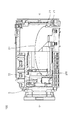
図1は、本発明の実施例によるレンズ鏡筒100のWIDE位置における断面図である。レンズ鏡筒100の光学系は、複数の光学部材の一例としての、第1レンズ群10、第2レンズ群20、第3レンズ群30、第4レンズ群40で構成され、それらのレンズ群を通る光線が光軸O上に配置された撮像素子9で結像し、映像が撮影される。
FIG. 1 is a cross-sectional view of the
撮像素子9は撮像素子保持部材8を介して後部筺体部材7に固定されている。第1レンズ群10は第1レンズ1と1群レンズ枠11で構成されており、第1レンズ1を保持した1群レンズ枠11は前部筺体部材6に固定されている。第2レンズ群20は第2レンズ2と2群レンズ枠21で構成されており、前部筺体部材6と後部筺体部材7の中で光軸方向に進退可能に保持されている。第2レンズ2はレンズ鏡筒100の変倍動作に関わるレンズであり、第2レンズ群20が光軸方向に進退することによってレンズ鏡筒100の変倍動作が行われる。第3レンズ群30は第3レンズ3と3群レンズ枠31で構成されており、前部筺体部材6と後部筺体部材7の中で光軸方向に進退可能に保持されている。第3レンズ3はレンズ鏡筒100の合焦動作に関わるレンズであり、第3レンズ群30が光軸方向に進退することによってレンズ鏡筒100の変倍動作が行われる。第4レンズ群40は第4レンズ4と4群レンズ枠41で構成されており、前部筺体部材6と後部筺体部材7の中で光軸方向に進退可能に保持されている。第4レンズ4はレンズ鏡筒100の変倍動作に関わるレンズであり、第4レンズ群40が光軸方向に進退することによってレンズ鏡筒100の変倍動作が行われる。
The image pickup element 9 is fixed to the
絞りユニット5は、絞りユニット5の開口径を変化させることによりレンズ鏡筒100の光量を調節する。絞りユニット5は、絞り駆動部52によって羽根部材を駆動する事によって開口径を変えている。絞りユニット5は2群レンズ枠21に保持されており、レンズ鏡筒100の変倍動作によって、2群レンズ枠21と一体に光軸方向に進退する。
The
絞り駆動部52には、図2に示すように、外部から入力を伝達するための絞りFPC51が電気的に接続されている。絞りFPC51(フレキシブルプリント回路基板)は、レンズ鏡筒100の内部から後部筐体部材7の外部に引き出され、外部電源と接続される。
As shown in FIG. 2, a
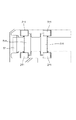
<絞りFPC51の構造>
図2は本発明の実施例によるレンズ鏡筒100のWIDE位置における要部断面図であり、レンズ鏡筒100の正姿勢状態において鉛直方向上から見た図である。図3は本発明の実施例によるレンズ鏡筒100のTELE位置における要部断面図であり、図2と同様に、レンズ鏡筒100の正姿勢状態において鉛直方向上から見た図である。図4は本発明の実施例によるレンズ鏡筒100のTELE位置における断面図である。
<Structure of aperture FPC51>
FIG. 2 is a cross-sectional view of a main part of the
レンズ鏡筒100はWIDE状態において第2レンズ群20が最も光軸方向後側に位置し、TELE状態において第2レンズ群20が最も光軸方向前側に位置する構成となっている。具体的には、第2レンズ群20は、図2に示すように、レンズ鏡筒100がWIDEの状態では、レンズ鏡筒100がTELEの状態のときよりも、光軸方向の撮像素子9の側に位置する。また、第2レンズ群20は、図3に示すように、レンズ鏡筒100がTELEの状態では、レンズ鏡筒100がWIDEの状態のときよりも、第1レンズ群10の側に位置している。
The
絞りFPC51は長手形状の部材であり、一方の端部は絞り駆動部52の近傍において、2群レンズ枠21の移動群側FPC保持部211(第1固定部)に固定されている。また、他方の端部は、後部筺体部材7の固定群側FPC保持部71(第2固定部)に固定されている。よって、第2レンズ群20が光軸方向に進退する動作に伴い、絞りFPC51は屈曲動作を繰り返すことになる。
The
また、固定群側FPC保持部71と移動群側FPC保持部211の位置関係は、光軸方向において移動群側FPC保持部211が前、固定群側FPC保持部71が後ろとなっている。水平方向に関して、移動群側FPC保持部211及び固定群側FPC保持部71は、光軸を含み、正姿勢状態時の鉛直方向に延びる面で分断される領域の同じ側に位置する。さらに、水平方向に関して、移動群側FPC保持部211及び固定群側FPC保持部71は、レンズ鏡筒100の筐体からはみ出さない範囲において、より光軸から離間した位置に配置している。また、後部筺体部材7には、図4に示すように、光軸方向に延びるFPC壁部72が設けられている。よって、絞りFPC52が鉛直方向に撓んだ場合にも、絞りFPC52が第3レンズ群30や第4レンズ群40に接触することを抑制できる。
Further, regarding the positional relationship between the fixed group side
絞りFPC51は、レンズ鏡筒100がWIDE状態の場合において、屈曲部510と、その前後の前側直線部513及び後側直線部514と、からなる。前側直線部513及び後側直線部514は略平行に配置されている。また、前側直線部513及び後側直線部514は、レンズ鏡筒100がWIDE状態の場合において、レンズ鏡筒100の正姿勢状態における水平方向に並行な方向に対して長手となっている。また、屈曲部510は、レンズ鏡筒100の正姿勢状態における鉛直方向に延びる軸線周りに屈曲するような形状となっている。また、絞りFPC51は、レンズ鏡筒100がTELE状態の場合において、光軸方向に関して長手となる。
The
また、絞りFPC51を収容するためのスペースは、第2レンズ群20の移動ストローク領域と略一致している。そのため、収容のためにレンズ鏡筒100を大型化する必要はない。
Further, the space for accommodating the
また、絞りFPC51はWIDE状態において撓みが最も大きくなる。絞りFPC51は過度な負荷がかかることを回避するため、TELE状態においてもある程度の撓みを持つようにする必要があるが、その場合、WIDE状態での撓みが大きくなるため、収容に要するスペースが非常に大きくなる。しかしながら、移動群側FPC保持部211及び固定群側FPC保持部71を、上記のような位置関係で配置することによって、レンズ鏡筒100の水平方向スペースを最大限に活用することが可能となる。よって、レンズ鏡筒100を必要以上に大型化する必要はない。
Further, the
<絞りFPC51の保持構造>
上述したように、絞りFPC51の一方の端部は、2群レンズ枠21の移動群側FPC保持部211に固定されており、他方の端部は後部筺体部材7の固定群側FPC保持部71に固定されている。以下に、この保持構造の詳細について説明する。図5は本発明の実施例によるレンズ鏡筒の分解斜視図である。
<Aperture FPC51 holding structure>
As described above, one end of the
図6は本発明の実施例によるレンズ鏡筒の移動群側FPC保持部の詳細図である。絞りFPC51に設けられた移動群係合部511は、絞りFPC51の外形より突出する形状を持つ2つの補強板によって構成されており、絞りFPC51の長手方向において並んで配置されている。また、2群レンズ枠21に設けられた移動群側FPC保持部211は4つの爪によって構成されており、移動群係合部511に2つずつ係合する事で、絞りFPCの位置と姿勢を規制しながら保持している。
FIG. 6 is a detailed view of the FPC holding portion on the moving group side of the lens barrel according to the embodiment of the present invention. The moving
図7は本発明の実施例によるレンズ鏡筒の固定群側FPC保持部の詳細図である。絞りFPC51に設けられた固定群係合部512は絞りFPC51の外形より突出する形状を持つ2つの補強板によって構成されており、絞りFPC51の長手方向において並んで配置されている。また、後部筺体部材7に設けられた固定群側FPC保持部71は4つの爪によって構成されており、固定群係合部512に2つずつ係合する事で、絞りFPCの位置と姿勢を規制しながら保持している。
FIG. 7 is a detailed view of the fixed group side FPC holding portion of the lens barrel according to the embodiment of the present invention. The fixed
よって、絞りFPC51は移動群係合部511と固定群係合部512にてそれぞれ位置と姿勢を規制されて保持されるため、第2レンズ群20が進退する間も常に水平姿勢を保持しており、鉛直方向に振れることを抑制できる。
Therefore, since the position and orientation of the
また、絞りFPC51は、移動群側FPC保持部の近傍および固定群側FPC保持部の近傍以外で他の部材と接触しないように配置されている。よって、絞りFPC51が、他の部材に接触することによって摩耗することを抑制できる。
Further, the
<絞りFPC51の配置>
図8は本発明の実施例によるレンズ鏡筒の光軸方向から見た要部分解図である。22は2群レンズ枠21と係合し、第2レンズ群20を光軸方向に進退可能に案内及び保持する2群支持部材である。23は2群レンズ枠21と係合し、第2レンズ群20を光軸方向に進退させるための2群駆動部である。
<Arrangement of aperture FPC51>
FIG. 8 is an exploded view of a main part of the lens barrel as viewed from the optical axis direction according to the embodiment of the present invention.
32は3群レンズ枠31及び4群レンズ枠41と係合し、第3レンズ群30及び第4レンズ群40を光軸方向に進退可能に案内及び保持する3群4群支持部材である。33は3群レンズ枠31と係合し、第3レンズ群30を光軸方向に進退させるための3群駆動部である。43は4群レンズ枠41と係合し、第4レンズ群40を光軸方向に進退させるための4群駆動部である。
レンズ鏡筒100の光軸方向垂直面における投影面積の大小は絞りユニットの外形で大きく左右される。また、レンズ移動群の支持部材22、32や駆動部23、33、43は光軸方向に関して長手であるため、光軸方向垂直面においては絞りユニットと重複して配置することができない場合が多い。そのため、レンズ移動群の支持部材22、32及び駆動部23、33、43、絞りユニットの光軸方向垂直面における配置に関して、レンズ鏡筒100を大型化しないためのレイアウトには制約が多い。よって、絞りユニット外形近傍の限られたスペースで光軸周方向に配置する必要がある。また、さらに、絞りユニットのFPCを収容するスペースを別途設けようとすると、レンズ鏡筒外形に対して凸となってしまう。絞りユニットの駆動部は一般的に絞りユニット外形から凸となっている場合が多いが、前述のようにこの位置に光軸方向長手部材を配置することができないため、従来、デッドスペースとなる場合が多かった。
The size of the projected area of the
本発明のレンズ鏡筒100は、絞りユニット5の絞り駆動部52と絞りFPC51を光軸方向垂直面において重畳するように配置することでこのデッドスペースを有効活用し、装置の大型化を防いでいる。このような構成とすることで、レンズ鏡筒100の外形を大型化する事なく、絞りFPC51の屈曲部510の曲率を大きくすることが可能となり、装置を大型化することなく屈曲するFPCの耐久性を向上させることができる。
In the
以上により、電気ユニットが光軸方向に進退するレンズ鏡筒において、装置を大型化する事なく、電気ユニットに接続されたFPCの屈曲耐久性を向上することを可能にすることができる。 As described above, in the lens barrel in which the electric unit moves forward and backward in the optical axis direction, it is possible to improve the bending durability of the FPC connected to the electric unit without increasing the size of the device.
以上、本発明の好ましい実施形態について説明したが、本発明はこれらの実施形態に限定されず、その要旨の範囲内で種々の変形及び変更が可能である。また設計機能を考慮した構成であれば、それを限定するものではない。 Although the preferred embodiments of the present invention have been described above, the present invention is not limited to these embodiments, and various modifications and modifications can be made within the scope of the gist thereof. Further, the configuration is not limited as long as the configuration considers the design function.
100 レンズ鏡筒
1 第1レンズ
10 第1レンズ群
11 1群レンズ枠
2 第2レンズ
20 第2レンズ群
21 2群レンズ枠
211 移動群側FPC保持部
22 2群支持部材
23 2群駆動部
3 第3レンズ
30 第3レンズ群
31 3群レンズ枠
32 3群4群支持部材
33 3群駆動部
4 第4レンズ
40 第4レンズ群
41 4群レンズ枠
43 4群駆動部
5 絞りユニット
51 絞りFPC
510 屈曲部
511 移動群係合部
512 固定群係合部
513 前側長手部
514 後側長手部
52 絞り駆動部
6 前部筺体部材
7 後部筺体部材
71 固定群側FPC保持部
72 FPC壁部
8 撮像素子保持部材
9 撮像素子
100
510
Claims (5)
前記筐体内に配置され、前記レンズを保持するとともに前記レンズの光軸方向に移動可能なレンズ保持枠と、
前記レンズ保持枠に保持される駆動部を備えた電気ユニットと、
前記筐体に保持された基板と、
一方の端部が前記基板に接続されるとともに他方の端部が前記駆動部に接続されるフレキシブルプリント回路基板と、を備え、
前記フレキシブルプリント回路基板は、前記レンズ保持枠が前記レンズの光軸方向に物体側から像側へ移動するのに伴って、前記光軸方向に沿うように延びる状態から、前記光軸と直交する軸を中心として屈曲することで、前記光軸と直交する方向に見て前記光軸と交差するように前記光軸と略直交する方向に延びる複数の直線部および屈曲部からなる略U字形状となるように撓むとともに、前記レンズの光軸方向に見て前記駆動部と重なる位置に配置されていることを特徴とするレンズ鏡筒。 The housing that houses the lens and
A lens holding frame that is arranged in the housing and can hold the lens and move in the optical axis direction of the lens.
An electric unit having a drive unit held by the lens holding frame and
The substrate held in the housing and
A flexible printed circuit board with one end connected to the board and the other end connected to the drive.
The flexible printed circuit board is orthogonal to the optical axis from a state in which the lens holding frame extends along the optical axis direction as the lens holding frame moves from the object side to the image side in the optical axis direction of the lens. A substantially U-shape composed of a plurality of straight portions and bent portions extending in a direction substantially orthogonal to the optical axis so as to intersect the optical axis when viewed in a direction orthogonal to the optical axis by bending around the axis. The lens barrel is bent so as to be such that the lens barrel is arranged at a position where it overlaps with the driving unit when viewed in the optical axis direction of the lens.
前記第1固定部および前記第2固定部は、前記光軸と略平行な第1直線上に配置されることを特徴とする、請求項1または2に記載のレンズ鏡筒。 The one end of the flexible printed circuit board is fixed to a first fixing portion provided on the lens holding frame, and the other end of the flexible printed circuit board is provided on the housing. 2 Fixed to the fixed part,
The lens barrel according to claim 1 or 2, wherein the first fixing portion and the second fixing portion are arranged on a first straight line substantially parallel to the optical axis.
Priority Applications (4)
| Application Number | Priority Date | Filing Date | Title |
|---|---|---|---|
| JP2018042444A JP6961516B2 (en) | 2018-03-08 | 2018-03-08 | Lens barrel |
| US16/291,393 US11106001B2 (en) | 2018-03-08 | 2019-03-04 | Lens barrel |
| EP19160807.4A EP3537202A1 (en) | 2018-03-08 | 2019-03-05 | Lens barrel |
| CN201910167196.6A CN110244427A (en) | 2018-03-08 | 2019-03-06 | Lens barrel |
Applications Claiming Priority (1)
| Application Number | Priority Date | Filing Date | Title |
|---|---|---|---|
| JP2018042444A JP6961516B2 (en) | 2018-03-08 | 2018-03-08 | Lens barrel |
Publications (3)
| Publication Number | Publication Date |
|---|---|
| JP2019158978A JP2019158978A (en) | 2019-09-19 |
| JP2019158978A5 JP2019158978A5 (en) | 2020-02-13 |
| JP6961516B2 true JP6961516B2 (en) | 2021-11-05 |
Family
ID=65717790
Family Applications (1)
| Application Number | Title | Priority Date | Filing Date |
|---|---|---|---|
| JP2018042444A Active JP6961516B2 (en) | 2018-03-08 | 2018-03-08 | Lens barrel |
Country Status (4)
| Country | Link |
|---|---|
| US (1) | US11106001B2 (en) |
| EP (1) | EP3537202A1 (en) |
| JP (1) | JP6961516B2 (en) |
| CN (1) | CN110244427A (en) |
Family Cites Families (13)
| Publication number | Priority date | Publication date | Assignee | Title |
|---|---|---|---|---|
| JP3428354B2 (en) * | 1997-03-31 | 2003-07-22 | ミノルタ株式会社 | Electrical connection mechanism in the lens barrel |
| JPH11218669A (en) * | 1998-01-30 | 1999-08-10 | Canon Inc | Flexible printed wiring board connecting structure in lens barrel |
| JP2000147355A (en) * | 1998-11-11 | 2000-05-26 | Nikon Corp | Variable focal distance lens barrel |
| JP2001194570A (en) * | 2000-01-06 | 2001-07-19 | Canon Inc | Structure for supporting flexible printed wiring of lens barrel |
| JP4612755B2 (en) * | 2000-02-21 | 2011-01-12 | キヤノン株式会社 | Lens barrel and optical equipment |
| JP4474201B2 (en) | 2004-05-26 | 2010-06-02 | キヤノン株式会社 | Lens barrel and camera |
| JP4855001B2 (en) * | 2005-07-25 | 2012-01-18 | Hoya株式会社 | Imaging module |
| JP2009139573A (en) | 2007-12-05 | 2009-06-25 | Fujinon Corp | Lens barrel and imaging apparatus |
| KR101567813B1 (en) * | 2008-12-31 | 2015-11-11 | 삼성전자주식회사 | Lens barrel assembly and camera having the same |
| JP5634172B2 (en) | 2010-08-31 | 2014-12-03 | キヤノン株式会社 | Lens barrel and optical apparatus having the same |
| KR20120133649A (en) * | 2011-05-31 | 2012-12-11 | 삼성전자주식회사 | Rens barrel assembly |
| JP2014191164A (en) * | 2013-03-27 | 2014-10-06 | Canon Inc | Lens barrel, interchangeable lens, and imaging apparatus |
| JP2016099538A (en) * | 2014-11-25 | 2016-05-30 | キヤノン株式会社 | Electronic apparatus |
-
2018
- 2018-03-08 JP JP2018042444A patent/JP6961516B2/en active Active
-
2019
- 2019-03-04 US US16/291,393 patent/US11106001B2/en active Active
- 2019-03-05 EP EP19160807.4A patent/EP3537202A1/en not_active Withdrawn
- 2019-03-06 CN CN201910167196.6A patent/CN110244427A/en active Pending
Also Published As
| Publication number | Publication date |
|---|---|
| EP3537202A1 (en) | 2019-09-11 |
| US20190278049A1 (en) | 2019-09-12 |
| US11106001B2 (en) | 2021-08-31 |
| CN110244427A (en) | 2019-09-17 |
| JP2019158978A (en) | 2019-09-19 |
Similar Documents
| Publication | Publication Date | Title |
|---|---|---|
| JP5832264B2 (en) | interchangeable lens | |
| KR20120133649A (en) | Rens barrel assembly | |
| JP6961516B2 (en) | Lens barrel | |
| JP5435045B2 (en) | Lens barrel and camera | |
| JP2009128593A (en) | Lens barrel and camera | |
| JP5822558B2 (en) | Lens barrel and camera system | |
| JP6235388B2 (en) | Imaging device | |
| JP6020816B2 (en) | Lens barrel | |
| JP2008122541A (en) | Zoom lens barrel and imaging apparatus with same | |
| JP2009282328A (en) | Arrangement method of flexible printed circuit board in lens barrel of imaging apparatus, and imaging apparatus using flexible printed circuit board employing the arrangement method of flexible printed circuit board | |
| JP6405118B2 (en) | Imaging device | |
| JP2010107788A (en) | Imaging apparatus | |
| JP6100068B2 (en) | Imaging device and network camera | |
| JP2019184976A (en) | Lens barrel | |
| JP2004205610A (en) | Camera | |
| JP6022367B2 (en) | Photography lens, imaging device, and optical element | |
| US11555980B2 (en) | Lens barrel and camera including the lens barrel | |
| JP7199955B2 (en) | lens barrel | |
| JP2016218246A (en) | Lens barrel and optical instrument | |
| WO2024135073A1 (en) | Lens device | |
| JP4844312B2 (en) | Lens barrel, optical equipment | |
| JP2019158978A5 (en) | ||
| JP2014145881A (en) | Monitoring camera | |
| JP2012128348A (en) | Lens barrel | |
| JP2012185376A (en) | Lens barrel and photographing device |
Legal Events
| Date | Code | Title | Description |
|---|---|---|---|
| A521 | Written amendment |
Free format text: JAPANESE INTERMEDIATE CODE: A523 Effective date: 20191223 |
|
| A621 | Written request for application examination |
Free format text: JAPANESE INTERMEDIATE CODE: A621 Effective date: 20191223 |
|
| A977 | Report on retrieval |
Free format text: JAPANESE INTERMEDIATE CODE: A971007 Effective date: 20200817 |
|
| A131 | Notification of reasons for refusal |
Free format text: JAPANESE INTERMEDIATE CODE: A131 Effective date: 20200901 |
|
| A521 | Written amendment |
Free format text: JAPANESE INTERMEDIATE CODE: A523 Effective date: 20201029 |
|
| A131 | Notification of reasons for refusal |
Free format text: JAPANESE INTERMEDIATE CODE: A131 Effective date: 20210323 |
|
| A521 | Written amendment |
Free format text: JAPANESE INTERMEDIATE CODE: A523 Effective date: 20210519 |
|
| TRDD | Decision of grant or rejection written | ||
| A01 | Written decision to grant a patent or to grant a registration (utility model) |
Free format text: JAPANESE INTERMEDIATE CODE: A01 Effective date: 20210914 |
|
| A61 | First payment of annual fees (during grant procedure) |
Free format text: JAPANESE INTERMEDIATE CODE: A61 Effective date: 20211013 |
|
| R151 | Written notification of patent or utility model registration |
Ref document number: 6961516 Country of ref document: JP Free format text: JAPANESE INTERMEDIATE CODE: R151 |