JP6960980B2 - Image-based tray alignment and tube slot positioning in visual systems - Google Patents
Image-based tray alignment and tube slot positioning in visual systems Download PDFInfo
- Publication number
- JP6960980B2 JP6960980B2 JP2019229826A JP2019229826A JP6960980B2 JP 6960980 B2 JP6960980 B2 JP 6960980B2 JP 2019229826 A JP2019229826 A JP 2019229826A JP 2019229826 A JP2019229826 A JP 2019229826A JP 6960980 B2 JP6960980 B2 JP 6960980B2
- Authority
- JP
- Japan
- Prior art keywords
- tray
- tube
- camera
- coordinate system
- marker
- Prior art date
- Legal status (The legal status is an assumption and is not a legal conclusion. Google has not performed a legal analysis and makes no representation as to the accuracy of the status listed.)
- Active
Links
Images


Classifications
-
- G—PHYSICS
- G01—MEASURING; TESTING
- G01N—INVESTIGATING OR ANALYSING MATERIALS BY DETERMINING THEIR CHEMICAL OR PHYSICAL PROPERTIES
- G01N35/00—Automatic analysis not limited to methods or materials provided for in any single one of groups G01N1/00 - G01N33/00; Handling materials therefor
- G01N35/00584—Control arrangements for automatic analysers
- G01N35/00722—Communications; Identification
- G01N35/00732—Identification of carriers, materials or components in automatic analysers
-
- G—PHYSICS
- G01—MEASURING; TESTING
- G01N—INVESTIGATING OR ANALYSING MATERIALS BY DETERMINING THEIR CHEMICAL OR PHYSICAL PROPERTIES
- G01N35/00—Automatic analysis not limited to methods or materials provided for in any single one of groups G01N1/00 - G01N33/00; Handling materials therefor
- G01N35/00584—Control arrangements for automatic analysers
- G01N35/00594—Quality control, including calibration or testing of components of the analyser
- G01N35/00693—Calibration
-
- G—PHYSICS
- G01—MEASURING; TESTING
- G01N—INVESTIGATING OR ANALYSING MATERIALS BY DETERMINING THEIR CHEMICAL OR PHYSICAL PROPERTIES
- G01N35/00—Automatic analysis not limited to methods or materials provided for in any single one of groups G01N1/00 - G01N33/00; Handling materials therefor
- G01N35/02—Automatic analysis not limited to methods or materials provided for in any single one of groups G01N1/00 - G01N33/00; Handling materials therefor using a plurality of sample containers moved by a conveyor system past one or more treatment or analysis stations
- G01N35/04—Details of the conveyor system
-
- G—PHYSICS
- G06—COMPUTING; CALCULATING OR COUNTING
- G06T—IMAGE DATA PROCESSING OR GENERATION, IN GENERAL
- G06T7/00—Image analysis
- G06T7/0002—Inspection of images, e.g. flaw detection
- G06T7/0012—Biomedical image inspection
-
- G—PHYSICS
- G06—COMPUTING; CALCULATING OR COUNTING
- G06T—IMAGE DATA PROCESSING OR GENERATION, IN GENERAL
- G06T7/00—Image analysis
- G06T7/70—Determining position or orientation of objects or cameras
- G06T7/73—Determining position or orientation of objects or cameras using feature-based methods
- G06T7/75—Determining position or orientation of objects or cameras using feature-based methods involving models
-
- G—PHYSICS
- G01—MEASURING; TESTING
- G01N—INVESTIGATING OR ANALYSING MATERIALS BY DETERMINING THEIR CHEMICAL OR PHYSICAL PROPERTIES
- G01N35/00—Automatic analysis not limited to methods or materials provided for in any single one of groups G01N1/00 - G01N33/00; Handling materials therefor
- G01N35/00584—Control arrangements for automatic analysers
- G01N35/00722—Communications; Identification
- G01N35/00732—Identification of carriers, materials or components in automatic analysers
- G01N2035/00742—Type of codes
- G01N2035/00772—Type of codes mechanical or optical code other than bar code
-
- G—PHYSICS
- G01—MEASURING; TESTING
- G01N—INVESTIGATING OR ANALYSING MATERIALS BY DETERMINING THEIR CHEMICAL OR PHYSICAL PROPERTIES
- G01N35/00—Automatic analysis not limited to methods or materials provided for in any single one of groups G01N1/00 - G01N33/00; Handling materials therefor
- G01N35/00584—Control arrangements for automatic analysers
- G01N35/00722—Communications; Identification
- G01N35/00732—Identification of carriers, materials or components in automatic analysers
- G01N2035/00821—Identification of carriers, materials or components in automatic analysers nature of coded information
- G01N2035/00851—Identification of carriers, materials or components in automatic analysers nature of coded information process control parameters
-
- G—PHYSICS
- G01—MEASURING; TESTING
- G01N—INVESTIGATING OR ANALYSING MATERIALS BY DETERMINING THEIR CHEMICAL OR PHYSICAL PROPERTIES
- G01N35/00—Automatic analysis not limited to methods or materials provided for in any single one of groups G01N1/00 - G01N33/00; Handling materials therefor
- G01N35/02—Automatic analysis not limited to methods or materials provided for in any single one of groups G01N1/00 - G01N33/00; Handling materials therefor using a plurality of sample containers moved by a conveyor system past one or more treatment or analysis stations
- G01N35/04—Details of the conveyor system
- G01N2035/0401—Sample carriers, cuvettes or reaction vessels
- G01N2035/0418—Plate elements with several rows of samples
-
- G—PHYSICS
- G06—COMPUTING; CALCULATING OR COUNTING
- G06T—IMAGE DATA PROCESSING OR GENERATION, IN GENERAL
- G06T2207/00—Indexing scheme for image analysis or image enhancement
- G06T2207/10—Image acquisition modality
- G06T2207/10016—Video; Image sequence
-
- G—PHYSICS
- G06—COMPUTING; CALCULATING OR COUNTING
- G06T—IMAGE DATA PROCESSING OR GENERATION, IN GENERAL
- G06T2207/00—Indexing scheme for image analysis or image enhancement
- G06T2207/30—Subject of image; Context of image processing
- G06T2207/30004—Biomedical image processing
- G06T2207/30024—Cell structures in vitro; Tissue sections in vitro
-
- G—PHYSICS
- G06—COMPUTING; CALCULATING OR COUNTING
- G06T—IMAGE DATA PROCESSING OR GENERATION, IN GENERAL
- G06T2207/00—Indexing scheme for image analysis or image enhancement
- G06T2207/30—Subject of image; Context of image processing
- G06T2207/30204—Marker
- G06T2207/30208—Marker matrix
Description
関連出願
本出願は、2015年2月18日に出願された「IMAGE−BASED TRAY ALIGNMENT AND TUBE SLOT LOCALIZATION IN A VISION SYSTEM」と題する米国仮出願第62/117,912号明細書に対する優先権を請求し、この開示は、参照により全体が本明細書に組み込まれる。
Related Application This application claims priority over US Provisional Application No. 62 / 117,912, entitled "IMAGE-BASED TRAY ALIGNMENT AND TUBE SLOT LOCALIZATION IN A VISION SYSTEM" filed on February 18, 2015. However, this disclosure is incorporated herein by reference in its entirety.
本明細書に開示された実施形態は、一般にチューブトレイの画像を取得してトレイとそのトレイ内に保持されたチューブの特性を決定することに関し、より詳細には基準マーカを使用してトレイを較正し位置合せして、トレイとそのトレイ内に保持されたチューブの特性を正確に決定することに関する。 The embodiments disclosed herein generally relate to taking an image of a tube tray to characterize the tray and the tubes held within the tray, and more particularly with reference markers. It relates to calibrating and aligning to accurately characterize the tray and the tubes held in the tray.
体外診断(IVD)は、検査室が、患者の液状サンプルに対して行われる検査に基づいて疾病診断を支援することを可能にする。IVDは、患者の体液又は膿瘍から得られた液体サンプルの分析によって行える患者の診断及び治療に関連した様々なタイプの分析試験及び検査を含む。そのような検査は、通常、患者サンプルを収容したチューブ又はガラス瓶が装填された自動臨床化学分析装置(分析装置)によって行われる。最新IVD検査で様々な検査が必要とされ、検査を行うのに大量の試験が必要なので、単一検査室内で複数の分析装置が使用されることが多い。分析装置の間では自動化システムも使用されうる。サンプルは、診療室から検査室に送られ、検査室に保管され、自動化システム又は分析装置に入れられ、その後の試験のために保管されうる。 In Vitro Diagnosis (IVD) allows laboratories to assist in disease diagnosis based on tests performed on a patient's liquid sample. IVD includes various types of analytical tests and tests related to patient diagnosis and treatment that can be performed by analysis of fluid samples obtained from the patient's body fluids or abscesses. Such tests are usually performed by an automated clinical chemistry analyzer (analyzer) loaded with a tube or glass bottle containing the patient sample. Due to the variety of tests required in the latest IVD tests and the large number of tests required to perform the tests, multiple analyzers are often used in a single laboratory. Automation systems may also be used among the analyzers. Samples can be sent from the clinic to the laboratory, stored in the laboratory, placed in an automated system or analyzer, and stored for subsequent testing.
分析装置間の保管と移送は、典型的には、トレイを使って行われる。トレイは、典型的には、テストチューブ内に蓄えられたいくつかの患者サンプルの配列である。そのようなトレイは、しばしば積み重ね可能であり、検査室の一部分から別の部分への複数サンプルの容易な搬送を可能にする。例えば、検査室は、病院又は診療所から試験のために患者サンプルのトレイを受け取ることがある。その患者サンプルトレイは、実験室内の冷蔵庫に保管されうる。患者サンプルトレイは、引出し内にも保管されうる。いくつかの自動化システムでは、分析装置は、患者サンプルトレイを受け入れ、サンプルをそれ相応に取り扱うことができ、一方、いくつかの分析装置は、サンプルがオペレータによってトレイから取り出され、さらなる処理の前にキャリア(パックなど)に入れられることを必要とすることがある。トレイは、一般に、サンプルを搬送し、場合によっては順番に配列することを可能にする受動装置である。 Storage and transfer between analyzers is typically done using trays. A tray is typically an array of several patient samples stored in a test tube. Such trays are often stackable, allowing easy transfer of multiple samples from one part of the laboratory to another. For example, a laboratory may receive a tray of patient samples for testing from a hospital or clinic. The patient sample tray can be stored in the refrigerator in the laboratory. The patient sample tray can also be stored in the drawer. In some automated systems, the analyzer can accept the patient sample tray and handle the sample accordingly, while in some analyzers the sample is removed from the tray by the operator and before further processing. May need to be placed in a carrier (pack, etc.). A tray is generally a passive device that allows samples to be transported and, in some cases, arranged in sequence.
一般に、トレイ内に保管されたサンプルチューブに関する情報は、オペレータ又はサンプル処理機構が各チューブと相互作用するまで分からない。例えば、サンプル取り扱いロボットアームが、チューブを取り上げ、トレイから取り出し、キャリアに入れることがある。次に、キャリアは、デキャッパステーションまで移動して、キャップがあれば除去し、バーコードリーダのそばを通り、それにより、チューブの側面のバーコードを読み取ってチューブの内容を明らかにできる。多くの先行技術のサンプル取り扱い機構では、チューブの識別は、チューブがトレイから取り出された後まで分からない。このように、トレイ内の全てのチューブは、チューブが自動化システム内の保持具上に配置されるまで同じように取り扱われることが多い。 In general, information about sample tubes stored in trays is not known until the operator or sample processing mechanism interacts with each tube. For example, a sample handling robot arm may pick up a tube, remove it from a tray, and place it in a carrier. The carrier can then move to the decapper station, remove any caps, pass by the bar code reader, and thereby read the bar code on the side of the tube to reveal the contents of the tube. In many prior art sample handling mechanisms, tube identification is not known until after the tube has been removed from the tray. As such, all tubes in the tray are often treated the same until the tubes are placed on a retainer in the automation system.
実施形態は、x軸とy軸を有するトレイ座標系と、x軸とy軸を有するカメラ座標系を使用するトレイ較正方法を提供する。この方法は、行と列の行列で配列された複数のチューブスロットを有するトレイの画像を取得することを含む。各チューブスロットは、サンプルチューブを収容するように構成され、トレイの画像が、カメラによって取得される。方法は、また、プロセッサを使用して、トレイ上のチューブスロット間の断面領域上に配置された複数の基準マーカを検出することと、トレイ座標系をカメラ座標系と予め位置合わせすることを含む。方法は、更に、プロセッサを使用して、平行線をトレイ座標系のx座標に沿ったマーカの位置に合わせ、対の平行線をトレイ座標系のy座標に沿った各行上のマーカの位置に合わせることによってトレイ格子を計算することと、プロセッサを使用して、各検出基準マーカの、トレイ上の物理位置に対する対応関係を識別して、トレイ座標系のカメラ座標系へのマッピングを提供することによってトレイを較正することとを含む。 The embodiment provides a tray calibration method using a tray coordinate system having x-axis and y-axis and a camera coordinate system having x-axis and y-axis. This method involves obtaining an image of a tray with multiple tube slots arranged in a row and column matrix. Each tube slot is configured to accommodate a sample tube and an image of the tray is captured by the camera. The method also includes using a processor to detect multiple reference markers located on the cross-sectional area between the tube slots on the tray and pre-aligning the tray coordinate system with the camera coordinate system. .. The method also uses a processor to align parallel lines to the marker positions along the x-coordinate of the tray coordinate system and pair parallel lines to the marker positions on each row along the y-coordinate of the tray coordinate system. Computing the tray grid by alignment and using a processor to identify the correspondence of each detection reference marker to its physical position on the tray and provide a mapping of the tray coordinate system to the camera coordinate system. Includes calibrating the tray by.
一実施形態によれば、トレイは、開位置と閉位置の間で移動可能な引出しの一部分に収まるように構成され、引出しが開位置と閉位置の間で移動されたときにトレイの画像がカメラによって取得される。 According to one embodiment, the tray is configured to fit within a portion of a drawer that is movable between the open and closed positions, and the image of the tray is displayed when the drawer is moved between the open and closed positions. Acquired by the camera.
別の実施形態によれば、方法は、カメラに隣接し別のカメラ座標系を有する別のカメラによってトレイの別の画像を取得することと、トレイ座標系を他のカメラ座標系と予め位置合わせすることと、各検出基準マーカの、トレイ上の物理位置との対応関係を識別して、トレイ座標系の他のカメラ座標系へのマッピングを提供することとを含む。 According to another embodiment, the method is to obtain another image of the tray by another camera that is adjacent to the camera and has a different camera coordinate system, and prealigns the tray coordinate system with the other camera coordinate system. This includes identifying the correspondence of each detection reference marker with its physical position on the tray and providing mapping of the tray coordinate system to other camera coordinate systems.
更に別の実施形態では、トレイ格子を計算することは、更に、検出マーカをトレイ座標系のx座標に沿ったクラスタにグループ化することを含み、各クラスタ内の検出マーカは、他のクラスタによって構成されたトレイ座標系のy方向の他の線に平行な、トレイ座標系のy方向の線内にある。 In yet another embodiment, computing the tray grid further comprises grouping the detection markers into clusters along the x-coordinate of the tray coordinate system, with the detection markers in each cluster being made by another cluster. Within the y-direction line of the tray coordinate system, parallel to the other y-direction lines of the configured tray coordinate system.
一実施形態の一態様によれば、複数の基準マーカは、白ドットである。 According to one aspect of one embodiment, the plurality of reference markers are white dots.
一実施形態では、トレイ格子を計算することは、更に、線形回帰を行なって、平行線をトレイ座標系のx座標に沿ったマーカの位置に合わせ、かつ対の平行線をトレイ座標系のy座標に沿った各行上のマーカの位置に合わせることを含む。断面領域は、概略菱形領域であり、概略菱形領域の各行上の基準マーカは、繰返し菱形領域の上角にある上角基準マーカと、繰返し菱形領域の右角にある右角基準マーカとを含む。 In one embodiment, computing the tray grid further performs a linear regression to align the parallel lines with the markers along the x-coordinate of the tray coordinate system and the pair of parallel lines to y in the tray coordinate system. Includes aligning the position of the marker on each row along the coordinates. The cross-sectional area is a schematic rhombus region, and reference markers on each row of the schematic rhombus region include an upper angle reference marker at the upper corner of the repeating rhombus region and a right angle reference marker at the right corner of the repeating rhombus region.
別の実施形態では、方法は、更に、各検出基準マーカの、トレイ上の物理位置との対応関係を使用して、オンライン動作中にトレイを位置合わせすることを含む。 In another embodiment, the method further comprises aligning the tray during online operation using the correspondence of each detection reference marker to its physical position on the tray.
更に別の実施形態では、トレイを較正することは、更に、次の式によって再投影誤差を最小にすることによってカメラの姿勢を導出することを含む。 In yet another embodiment, calibrating the tray further comprises deriving the camera orientation by minimizing the reprojection error by the following equation.
R,t = argminR,tΣi||pi- f(RPi+ t,Kc,dc)||2, R, t = argmin R, t Σi || p i --f (RP i + t, K c , d c ) || 2 ,
ここで、{Pi}と{pi}は、三次元及び二次元対応関係であり、f()は、カメラ座標系からその画像平面への三次元から二次元への投影関数であり、Kcは、焦点距離、及びカメラ軸と画像上の主点のスキューを含む本質的較正行列であり、dcは、そのレンズ歪みベクトルであり、回転行列Rと並進ベクトルtは、カメラ画像の姿勢を示す非本質的パラメータである。 Here, {P i } and { pi } are three-dimensional and two-dimensional correspondence relationships, and f () is a three-dimensional to two-dimensional projection function from the camera coordinate system to the image plane. K c is the focal length, and is essentially a calibration matrix containing a skew of the principal point of the camera axis and the image, d c is the lens distortion vector, rotation matrix R and translation vector t is the camera image It is a non-essential parameter indicating posture.
実施形態は、トレイ座標系とカメラ座標系を使用するチューブスロット位置特定方法を提供する。この方法は、プロセッサを使用して、行及び列の行列で配列されたチューブスロットを含むトレイの少なくとも1つのカメラから一連の画像を受け取ることを含む。各チューブスロットは、サンプルチューブを収容するように構成される。トレイの画像は、少なくとも1つのカメラによって取得される。方法は、また、プロセッサを使用して、トレイ上のチューブスロット間の断面領域上に配置された複数の基準マーカを自動的に検出することと、プロセッサを使用して、トレイの各行が実質的にカメラの視界の中心にあることを示すエンコーダ値を受け取ることを含む。方法は、更に、プロセッサを使用して、トレイ座標系からの位置のカメラ座標系からの位置へのマッピングを提供する較正情報を決定することと、プロセッサを使用して、エンコーダ値と較正情報に基づいてトレイを自動的に位置合わせすることを含む。 The embodiment provides a tube slot positioning method using a tray coordinate system and a camera coordinate system. The method involves using a processor to receive a series of images from at least one camera in a tray containing tube slots arranged in a row and column matrix. Each tube slot is configured to accommodate a sample tube. Images in the tray are acquired by at least one camera. The method also uses a processor to automatically detect multiple reference markers placed on the cross-sectional area between the tube slots on the tray, and uses the processor to effectively make each row in the tray. Includes receiving an encoder value that indicates that it is in the center of the camera's view. The method further uses a processor to determine calibration information that provides a mapping of positions from the tray coordinate system to positions from the camera coordinate system, and uses the processor to the encoder values and calibration information. Includes automatic alignment of trays based on.
一実施形態によれば、トレイは、開位置と閉位置の間で移動可能な引出しの一部分に収まるように構成され、引出しが開位置と閉位置の間で移動されたときに少なくとも1つのカメラによってトレイの画像が取得される。 According to one embodiment, the tray is configured to fit in a portion of a drawer that is movable between the open and closed positions, and at least one camera when the drawer is moved between the open and closed positions. Gets the image of the tray.
別の実施形態によれば、較正情報は、各検出基準マーカの、トレイ上の物理位置との対応関係を示す。 According to another embodiment, the calibration information indicates the correspondence of each detection reference marker with the physical position on the tray.
更に別の実施形態では、較正情報は、トレイのタイプ、トレイの向き及びトレイの位置を示す。プロセッサを使用してトレイを自動的に位置合わせすることは、エンコーダ値と較正情報に基づいて基準マーカの位置を予測することと、マーカの投影位置と検出マーカの位置との間のオフセットを自動的に決定することと、少なくとも1つのカメラの視界内にあるトレイとチューブスロットを位置合わせするようにオフセットを自動的に補償することとを含む。 In yet another embodiment, the calibration information indicates the tray type, tray orientation and tray position. Automatically aligning the tray using the processor predicts the position of the reference marker based on the encoder value and calibration information, and automatically offsets the offset between the projected position of the marker and the position of the detection marker. Includes deterministic determination and automatic compensation for offsets to align trays and tube slots within the field of view of at least one camera.
一実施形態では、方法は、更に、断面領域のそれぞれの中心におけるチューブスロット格子点を定義することと、補償されたチューブスロット格子点を一連の画像のうちの1つ以上に投影して、決定されたオフセットに基づいてチューブスロットを位置特定することとを含む。 In one embodiment, the method further determines by defining tube slot grid points at each center of the cross-sectional area and projecting the compensated tube slot grid points onto one or more of a series of images. Includes locating tube slots based on the offsets made.
別の実施形態では、方法は、更に、一連の画像の1つ以上から各チューブスロットに対応するデータを抽出して、チューブがチューブスロットのうちの1つを占有するかどうかとチューブタイプの少なくとも1つを決定する。 In another embodiment, the method further extracts data corresponding to each tube slot from one or more of a series of images to determine if the tube occupies one of the tube slots and at least the tube type. Determine one.
実施形態は、体外診断環境で使用される視覚システムを提供する。システムは、行と列の行列で配列された複数のチューブスロットを有するトレイを含む。各チューブスロットは、サンプルチューブを受け取るように構成される。トレイは、また、複数のチューブスロットと、断面領域上に配置された複数の基準マーカとの間に配置された複数の断面領域を含む。システムは、また、トレイを受けるように構成された表面と、表面に位置決めされたトレイの一連の画像を取得するように構成された少なくとも1つのカメラと、トレイの各行が実質的に少なくとも1つのカメラの視界の中心にあることを示すエンコーダ値を生成するように構成されたエンコーダとを含む。システムは、更に、少なくとも1つのカメラからトレイの一連の画像を受け取り、トレイ上のチューブスロット間の断面領域上に配置された複数の基準マーカを自動的に検出し、エンコーダ値を受け取り、トレイ座標系からの位置のカメラ座標系からの位置へのマッピングを提供する較正情報を生成し、エンコーダ値と較正情報とに基づいてトレイを自動的に位置合わせするように構成されたプロセッサを含む。 The embodiment provides a visual system used in an in vitro diagnostic environment. The system includes trays with multiple tube slots arranged in a row and column matrix. Each tube slot is configured to receive a sample tube. The tray also includes a plurality of cross-section areas located between the plurality of tube slots and a plurality of reference markers placed on the cross-section area. The system also includes a surface configured to receive the tray, at least one camera configured to capture a series of images of the tray positioned on the surface, and substantially at least one row of tray. Includes an encoder configured to generate an encoder value indicating that it is in the center of the camera's field of view. The system also receives a series of images of the tray from at least one camera, automatically detects multiple reference markers placed on the cross-sectional area between the tube slots on the tray, receives the encoder value, and receives the tray coordinates. Includes a processor configured to generate calibration information that provides a mapping of positions from the system to position from the camera coordinate system and automatically align the tray based on the encoder values and the calibration information.
一実施形態によれば、表面は、開位置と閉位置の間で移動可能な引出しを含み、引出しが開位置と閉位置の間で移動されたときにトレイの画像が少なくとも1つのカメラによって取得される。 According to one embodiment, the surface comprises a drawer that is movable between open and closed positions, and an image of the tray is acquired by at least one camera when the drawer is moved between open and closed positions. Will be done.
別の実施形態によれば、各断面領域は、概略菱形領域であり、各概略菱形領域は、複数チューブスロットのうちの4つの間に配置される。概略菱形領域の各行上の基準マーカは、繰返し菱形領域の上角にある上角基準マーカと、繰返し菱形領域の右角にある右角基準マーカとを含む。 According to another embodiment, each cross-sectional area is a schematic rhombic region, and each schematic rhombic region is located between four of a plurality of tube slots. Reference markers on each row of the generally rhombic region include an upper angle reference marker at the upper corner of the repeating rhombus region and a right angle reference marker at the right corner of the repeating rhombus region.
更に別の実施形態では、プロセッサは、更に、トレイ上のチューブスロット間の断面領域上に配置された複数の基準マーカを検出し、トレイ座標系をカメラ座標系と予め位置合わせし、トレイ座標系のx座標に沿ったマーカの位置に平行線を合わせ、トレイ座標系のy軸に沿った各行上のマーカの位置に対の平行線を合わせることによってトレイ格子を計算し、各検出基準マーカの、トレイ上の物理位置との対応関係を識別することによって較正情報を決定することによって、トレイ座標系からの位置のカメラ座標系からの位置へのマッピングを提供する較正情報を決定するように構成される。 In yet another embodiment, the processor further detects a plurality of reference markers located on the cross-sectional area between the tube slots on the tray, pre-aligns the tray coordinate system with the camera coordinate system, and tray coordinate system. The tray grid is calculated by aligning the parallel lines with the positions of the markers along the x-coordinate of, and aligning the pair of parallel lines with the positions of the markers on each row along the y-axis of the tray coordinate system. Configured to determine the calibration information that provides a mapping of the position from the tray coordinate system to the position from the camera coordinate system by determining the calibration information by identifying the correspondence with the physical position on the tray. Will be done.
実施形態は、視覚システムと共に使用するために表面に保持されるように構成されたトレイを提供する。トレイは、行及び列の行列で配列された複数のチューブスロットを含む。各チューブスロットは、サンプルチューブを受け取るように構成される。トレイは、また、複数の概略菱形領域を含む。各概略菱形領域は、複数チューブスロットのうちの4つの間に配置される。トレイは、更に、複数の基準マーカを含む。各基準マーカは、概略菱形領域のうちの1つの上に配置される。 The embodiment provides a tray configured to be held on the surface for use with a visual system. The tray contains multiple tube slots arranged in a row and column matrix. Each tube slot is configured to receive a sample tube. The tray also contains a plurality of schematic rhombic regions. Each schematic rhombic region is located between four of the multiple tube slots. The tray further contains a plurality of reference markers. Each reference marker is placed above one of the roughly diamond-shaped regions.
一実施形態によれば、概略菱形領域の各行上の基準マーカは、繰返し菱形領域の上角にある上角基準マーカと、繰返し菱形領域の右角にある右角基準マーカとを含む。 According to one embodiment, the reference marker on each row of the generally rhombic region includes an upper angle reference marker at the upper corner of the repeating rhombus region and a right angle reference marker at the right corner of the repeating rhombus region.
別の実施形態によれば、トレイは、更に、複数のばね力要素を含む。各ばね力要素は、チューブスロットに結合され、チューブがチューブスロット内の中心にならないようにサンプルチューブに力を働かせるように構成される。基準マーカは、サンプルチューブが対応チューブスロット内にあるときに、チューブスロットのそれぞれと隣接した少なくとも3つの基準マーカがカメラの視界内にあるようなパターンでトレイ上に配置される。 According to another embodiment, the tray further comprises a plurality of spring force elements. Each spring force element is coupled to the tube slot and is configured to exert a force on the sample tube so that the tube is not centered within the tube slot. Reference markers are arranged on the tray in a pattern such that at least three reference markers adjacent to each of the tube slots are in the camera's field of view when the sample tube is in the corresponding tube slot.
本開示の追加の特性及び利点は、添付図面を参照して進む説明的実施形態の以下の詳細な説明から明らかにされる。 Additional properties and advantages of the present disclosure will be apparent from the following detailed description of the explanatory embodiments that proceed with reference to the accompanying drawings.
本明細書に開示された実施形態の以上及び他の態様は、添付図面と関連して読むときに以下の詳細な説明から最もよく理解される。本明細書に開示された実施形態を例証するために、図には現在好ましい実施形態が示されるが、本明細書に開示された実施形態が、開示された特定の手段に限定されないことを理解されたい。図面には以下の図が含まれる。 The above and other aspects of the embodiments disclosed herein are best understood from the following detailed description when read in connection with the accompanying drawings. To illustrate the embodiments disclosed herein, the drawings now show preferred embodiments, but it is understood that the embodiments disclosed herein are not limited to the particular means disclosed. I want to be. The drawings include the following figures.
本出願は、参照により本明細書に組み込まれるPCT出願第PCT/US14/27217号、及びWuらによる米国仮出願第62/010370号明細書に記載された概念のいくつかに関する。 This application relates to some of the concepts described in PCT Application No. PCT / US14 / 27217, which is incorporated herein by reference, and US Provisional Application No. 62/010370 by Wu et al.
実施形態は、チューブトレイ及びそのチューブトレイ内に保持されたチューブの画像を取得するように構成された自動視覚システムにおいてチューブトレイを較正し位置合せするためのシステム及び方法を含む。いくつかの実施形態は、自動化システムにおいて手動で配置され位置合せされたトレイの画像を取得することを含む。例えば、自動化システムは、平坦面にガイドレールを提供し、オペレータがトレイ上のキー止め特性形状をレールに手動で位置合わせし、トレイを作業領域に押すことを可能にし得る。 Embodiments include a system and method for calibrating and aligning a tube tray in an automated visual system configured to capture an image of the tube tray and the tubes held within the tube tray. Some embodiments include acquiring images of manually placed and aligned trays in an automated system. For example, an automated system may provide a guide rail on a flat surface that allows an operator to manually align the keying characteristic shape on the tray with the rail and push the tray into the work area.
いくつかの実施形態は、サンプルチューブが収容されたチューブトレイを装填し取り出すための引出しを含む自動引出し視覚システム(DVS)を含みうる。トレイの画像は、引出しが開位置と閉位置(例えば、作業領域位置)の間で移動されたときに、引出しの入口領域の上に取り付けられた1つ以上のカメラによって取得されうる。高速運動下で取得された画像のチューブ特性の正確な評価を容易にするため、実施形態は、画像ごとにトレイ表面上の1組の基準マーカを利用してトレイが引出しと共に移動した距離を評価することを含む画像ベース方法を使用して、高精度なチューブサンプルトレイ位置合せ及びチューブスロット位置特定を提供する。実施形態は、また、DVSカメラごとに基準マーカパターンを位置合わせするための較正方式を含む。実施形態は、更に、トレイ位置合せ及びチューブスロット位置特定のためのテンプレート突き合わせ方法を含む。 Some embodiments may include an automatic drawer visual system (DVS) that includes a drawer for loading and unloading a tube tray containing a sample tube. The image of the tray can be acquired by one or more cameras mounted above the entrance area of the drawer as the drawer is moved between the open and closed positions (eg, the working area position). To facilitate an accurate assessment of the tube characteristics of images acquired under high speed motion, embodiments use a set of reference markers on the tray surface for each image to assess the distance the tray has traveled with the drawer. Image-based methods, including doing so, are used to provide accurate tube sample tray alignment and tube slot positioning. The embodiment also includes a calibration method for aligning a reference marker pattern for each DVS camera. The embodiment further includes a template matching method for tray alignment and tube slot positioning.
実施形態は、確実なトレイ位置合わせのためのアンカポイントを固有かつ容易に検出するとともに提供するための基準マーカとして単純な白ドットを使用することを含む。低解像度ドットパターンをトレイの上面に成形して、高精度な(例えば、ドット位置がCADモデルにきわめて近い)検出により効率的に製造されたトレイを提供できる。トレイ位置合わせには、基準マーカと共に効率的で頑強な低解像度ハードウェアエンコーダが使用されうる。引出し上のエンコーダストリップとフレーム上の光学スロットセンサ間の位置合わせ公差が大きいので、エンコーダカウントを失うことなくまたエンコーダシステムを較正する時間と費用をなくすことなく引出しを移動(例えば、曲げ、収縮、及び拡張)できる。また、光学スロットセンサを有するエンコーダストリップは、汚れ又はほこりに対して耐性を有している。 Embodiments include the use of simple white dots as reference markers to uniquely and easily detect and provide anchor points for reliable tray alignment. A low resolution dot pattern can be molded onto the top surface of the tray to provide an efficiently manufactured tray with highly accurate (eg, dot positions very close to the CAD model) detection. Efficient and robust low-resolution hardware encoders can be used with reference markers for tray alignment. The large alignment tolerance between the encoder strip on the drawer and the optical slot sensor on the frame allows the drawer to move (eg, bend, shrink, etc.) without losing encoder counts and without the time and expense of calibrating the encoder system. And expansion). Also, the encoder strip with the optical slot sensor is resistant to dirt or dust.
低解像度ドットパターンと低解像度ハードウェアエンコーダの組み合わせにより、トレイ内に成形できない高解像度の複雑なパターン(例えば、高精度マーカ配置、複雑なマーカ形状、又は多数のマーカ)のエッチング効率の低下が回避される。また、低解像度ドットパターンと低解像度ハードウェアエンコーダの組み合わせによって、トレイ位置合わせのための高価な高解像度ハードウェアエンコーダの使用が回避される。 The combination of low resolution dot patterns and low resolution hardware encoders avoids reduced etching efficiency for high resolution complex patterns that cannot be molded in the tray (eg, precision marker placement, complex marker shapes, or multiple markers). Will be done. Also, the combination of low resolution dot patterns and low resolution hardware encoders avoids the use of expensive high resolution hardware encoders for tray alignment.
PCT出願第PCT/US14/27217号明細書に記載されているように、DVSのチューブトレイは、引出し内に収まり、行と列の配列で配列されたスロット内に複数のチューブを保持するように構成される。画像は、トレイ並びにトレイ上に保持されたチューブを評価するために使用される。詳細には、実施形態によれば、画像を分析することによって、チューブの種々の特性(例えば、チューブを収容するトレイスロット、座標系におけるチューブの中心点、チューブの直径と高さ、引出し内のトレイの向き、チューブが単純チューブかどうか、チューブがキャップ又はチューブ上部カップで覆われているかどうか、チューブキャップの色、トレイ表面のバーコード、及びトレイを保持する引き出しが作業環境に挿入又は取り出される速度など)を決定できる。実施形態は、高価な機器なしにまたチューブを取り扱ったり触れたりせずにこの情報と他の情報を素早く決定する。そのような知識は、チューブの効率的で合理的な処理、並びにセットアップ及び維持コストの低減を可能にする。 As described in PCT Application No. PCT / US14 / 27217, the DVS tube tray should fit in a drawer and hold multiple tubes in slots arranged in a row and column array. It is composed. Images are used to evaluate trays and tubes held on trays. Specifically, according to an embodiment, by analyzing the image, various properties of the tube (eg, tray slot containing the tube, the center point of the tube in the coordinate system, the diameter and height of the tube, in the drawer. The orientation of the tray, whether the tube is a simple tube, whether the tube is covered with a cap or tube top cup, the color of the tube cap, the barcode on the tray surface, and the drawer that holds the tray are inserted or removed into the work environment. Speed etc.) can be determined. The embodiment quickly determines this and other information without expensive equipment and without handling or touching the tube. Such knowledge enables efficient and rational processing of tubes, as well as reduced setup and maintenance costs.
この情報は、サンプルハンドラがチューブを処理し、チューブを試験と分析のために分析装置まで移動させるIVD環境で貴重である。本発明の実施形態は、特にIVD環境に適しているが、決してIVD環境に限定されない。 This information is valuable in an IVD environment where the sample handler processes the tube and moves the tube to the analyzer for testing and analysis. Embodiments of the present invention are particularly suitable for IVD environments, but are by no means limited to IVD environments.
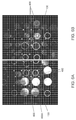
図1Aは、本発明の一実施形態による、チューブトレイ120とそこに収容されたチューブ130を、その画像を取得し分析することによって評価する例示的な引出し視覚システム100を表す。1つ以上の引出し110が、開位置と閉位置の間で移動可能であり、サンプルハンドラのための作業エンベロープ105内で提供される。1つ以上のチューブトレイ120が、引出し110に装填されてもよく、引出し110の永久機能でもよい。各チューブトレイ120は、チューブ130が収容されうるスロットの行と列の配列(例示的トレイ121内に描かれたような)を有する。
FIG. 1A represents an exemplary drawer
実施形態により、チューブトレイ120の画像が撮影される。画像は、チューブトレイ120とチューブ130の特性を決定するために分析される。画像をその分析のために取得するために、本明細書に提供された実施形態によれば、可動トレイ又は固定カメラ手法が使用される。チューブトレイ120が、例えば手動又は自動で引出し110に押し込まれることによって、作業エンベロープ105に入れられるとき、画像取得システム140を使用してチューブトレイ120とそこに収容されたチューブ130の画像を撮影する。
According to the embodiment, an image of the
画像取得システム140は、作業エンベロープ105の入口又は入口近くに位置決めされた1つ以上のカメラ(例えば、図2に示された左側カメラ242と右側カメラ244)を含みうる。いくつかの実施形態では、1つ以上のカメラ242、244が、チューブトレイ120の表面の上に位置決めされうる。例えば、カメラ242,244は、チューブトレイ120の高解像度画像を取得するために、表面の76.2〜152.4mm(3〜6インチ)上に配置されうる。カメラ242,244の機能並びに所望の視点及び画像品質により、他の距離及び/又は位置決めが使用されうる。必要に応じて、画像取得システム140は、LEDフラッシュなどの1つ以上の光源を含みうる。
The
図1Bは、本明細書に開示された実施形態と共に使用されうる例示的な引出し視覚システムの例示的な試験ハーネスを示す。図1Bに示されたように、画像取得システム140は、チューブ130を保持するチューブトレイ120の表面の上に位置決めされ、引出し110上に配置される。図1Bで実施形態に示された引出し110は、2つの55スロットトレイ又は6つの15スロットトレイを保持するように構成される。しかしながら、実施形態は、様々な数のスロットを有しかつ様々なサイズを有するトレイを保持するように構成されたトレイを含みうる。
FIG. 1B shows an exemplary test harness of an exemplary drawer visual system that can be used with the embodiments disclosed herein. As shown in FIG. 1B, the
図2は、一実施形態による、引出し110内に保持され収容されたチューブトレイ120とチューブ130を画像分析によって評価するためのシステム200を表すブロック図を示す。画像取得システム140は、一実施形態によれば、2つのカメラ、即ち左側カメラ242と右側カメラ244を含む。引出し110及びチューブトレイ120のサイズ、並びに望みの画質及び画像視点により、追加又はもっと少ないカメラが含まれうる。また、光源246及び画像取得コントローラ248は、画像取得システム140の一部である。
FIG. 2 shows a block diagram representing a
チューブトレイ120の行が、1つ以上のカメラ242,244の下の中心位置又は実質的中心位置に移動されたことを決定するために、直角位相エンコーダなどのエンコーダ210が使用されうる。エンコーダ210は、チューブトレイ120の新しい行に対応するチューブトレイ120が、1つ以上のカメラ242,244の下の中心位置又は実質的中心位置に移動したことの検出に基づいて、画像取得コントローラ248に信号(即ち、パルス)を送信する。信号は、画像取得コントローラ248が、信号の受信時にカメラ242,244に指示して画像を撮影させる命令として働く。
An
カメラ242,244によって撮影された画像の画像分析を管理するためのコントローラ220が提供される。引出し110が閉じたことを検出すると、画像取得コントローラ248は、ダウンロードと処理のためにコントローラ220に画像を提供する。コントローラ220は、一実施形態によれば、IVD環境で、チューブトレイ120とチューブ130を作業エンベロープ105などの保管場所の間で取り扱い、分析装置まで移動させるために使用されるサンプルハンドラの一部である。コントローラ220によって行われる画像分析は、チューブトレイ120とチューブ130の様々な決定された特性に基づいてサンプルハンドラに指示する役割をし、したがって、サンプルハンドラがそれに応じてチューブトレイ120とチューブ130を取り扱い処理することを可能にする。
A
1つ以上の記憶装置240が、コントローラ220と関連付けられる。1つ以上の記憶装置240は、コントローラ220の内部でも外部でもよい。
One or
引出し110が完全に閉じられかつ/又は引出し110が完全に開かれたことを示すために、1つ以上の引出しセンサ230がコントローラ220に接続されうる。一実施形態によれば、引出し110が完全に閉じられたことは、取得され記憶された画像の画像処理を始める指示として働く。引出し110が完全に閉められたとき、引出しセンサ230は、コントローラ220に信号を送る。
One or
図3は、トレイスロットタイプとサンプルチューブのチューブタイプを決定する方法300を示すフローチャートである。図3に示されたように、この方法は、ステップ306〜314によってトレイスロットタイプ(例えば、スロットが空か空でないか)を決定してもよくかつ/又はステップ316〜324によってチューブタイプ(例えば、単純チューブ、キャップ付きチューブ、又はチューブ上部サンプルカップ付きチューブ)を決定してもよい。トレイスロットタイプを決定する方法は、「Locality−based Detection of Tray Slot Types and Tube Types in a Drawer Vision System」と題する出願(整理番号2014P23283US)に、より詳細に記載されている。
FIG. 3 is a flowchart showing a
しかしながら、ステップ302で画像が取得された後、トレイスロットタイプを決定するステップ308に進む前に、ステップ304で、トレイ格子が位置合わせされ、ステップ306で、トレイスロットパッチが抽出される。以下の記述では、ステップ304でトレイ格子位置合わせに焦点を当て、ステップ306でトレイスロットパッチ抽出に焦点を当てる。
However, after the image is acquired in
従来の自動化システムは、チューブスロット占有検出に時間がかかる力任せの方法を実行する。そのような自動化システムには、高度なチューブ分類及び評価機能がない。これと対照的に、DVSは、引出し入口の上部に取り付けられた2つのカメラを利用して、引出し挿入中にサンプルチューブの画像を取得する。したがって、画像分析アルゴリズムを使用して取得画像にチューブ占有検出、チューブ分類及びチューブ評価が効率的に行われうる。 Traditional automation systems perform a brute force method that takes time to detect tube slot occupancy. Such automated systems do not have advanced tube classification and evaluation capabilities. In contrast, the DVS utilizes two cameras mounted above the drawer inlet to capture an image of the sample tube during drawer insertion. Therefore, tube occupancy detection, tube classification, and tube evaluation can be efficiently performed on the acquired image using an image analysis algorithm.
引き出し挿入中に引出しが高速運動しているときに画像が取得されるように、頑強なチューブスロット位置特定アルゴリズムが、チューブ高さ、直径、中心オフセットなどのチューブ特性を評価するための幾何学的基準として働くことが望ましい。ハードウェアエンコーダは、1組の所定位置にあるカメラをトリガできるが、高精度エンコーダはコスト効率がよくない。DVSカメラセットアップに関して、トレイスロット位置特定に関して1画素未満の誤差を達成するために、エンコーダ誤差は、0.13mm未満であることが望ましい。 Robust tube slot positioning algorithms geometrically evaluate tube characteristics such as tube height, diameter, and center offset so that images are acquired when the drawer is moving at high speed during drawer insertion. It is desirable to work as a standard. Hardware encoders can trigger a set of cameras in place, but precision encoders are not cost effective. For DVS camera setups, the encoder error is preferably less than 0.13 mm in order to achieve an error of less than one pixel with respect to tray slot positioning.
基準マーカ
高速運動下で取得された画像のチューブ特性の正確な評価を容易にするため、実施形態は、画像ごとにトレイ表面上の1組の標準マーカを利用してトレイが引き出しと共に移動した距離を評価することを含む画像ベース方法を使用することによって、高精度なチューブサンプルトレイ位置合せ及びチューブスロット位置特定を提供する。実施形態は、また、DVSカメラごとの基準マーカパターンを位置合せするための較正方法を含む。実施形態は、更に、トレイ整列及びチューブスロット位置特定のためのテンプレート突合わせ方法を含む。
Reference Marker To facilitate an accurate assessment of the tube characteristics of images acquired under high speed motion, embodiments utilize a set of standard markers on the tray surface for each image to determine the distance the tray has traveled with the drawer. By using an image-based method that involves evaluating the tube sample tray, it provides accurate tube sample tray alignment and tube slot positioning. The embodiment also includes a calibration method for aligning a reference marker pattern for each DVS camera. The embodiment further includes a template matching method for tray alignment and tube slot positioning.
図4は、一実施形態による、チューブスロット402間のトレイ120上に配置された基準マーカ400を有する例示的トレイ120の平面図である。1組4つの隣接スロット402の間に、ほぼ菱形の断面領域404(以下では、菱形領域)が配置される。図4に示されたように、トレイ120は、5列11行の行列を含む。図4に示されたスロット402の数、スロット402の行数、及びスロット402の列数は、例示に過ぎない。実施形態は、任意数の行、列及びスロットを有するトレイを含みうる。図4に示されたトレイ120の寸法も例示である。実施形態は、図4に示された寸法以外の寸法を有するトレイも含みうる。
FIG. 4 is a plan view of an
ハードウェアエンコーダの誤差が、トレイ120の行長さの半分(例えば、11.75mm)未満であると仮定することにより、トレイ120の各行に繰り返しマーカパターンが使用されうる。望ましい基準マーカパターンを提供するために、種々の因子が検討されうる。例えば、基準マーカ400の数が多いほどトラッキング結果が正確になる。したがって、可能な動作条件下でトラッキングに利用できるマーカ400の数を最大にしなければならない。更に、マーカ400の部分的な隠れ並びにチューブ側のマーカ反射によって位置特定誤差と誤検出が起こることがある。したがって、部分的にしか見えないマーカ400と側壁の反射の数を最小にしなければならない。
Repeated marker patterns can be used for each row of
図5は、一実施形態による、スロット402の隣の菱形領域内の基準マーカ400の位置を示す、図4に示されたトレイの一部分の拡大図である。図5に示されたように、チューブスロットは、カメラの視界内でマーカ(図5のマーカ400Aなど)を遮る可能性のあるチューブスロット402内に保持されたチューブ130を、チューブがチューブスロット内の中心でなくなるようにスロット402の1つの角の方に押すように構成されたばね500を含む。図5は、カメラの視界から遮られると予想される領域502と、カメラの視界内で見えると予想される領域504とを示す。したがって、各菱形領域404の中心にあるマーカ以外、マーカ402とチューブスロット402の中心間の距離が最大にされる。特定の構成により、スロット402内にチューブがあるかスロット402が空かにかかわらずカメラの視界内に少なくとも3つのマーカがあり、それにより、許容可能な精度範囲内のトラッキングが提供され、更に他のマーカの使用がなくなる。その結果、部分的に見えるマーカとチューブ壁上の反射の数が最小にされうる。
FIG. 5 is an enlarged view of a portion of the tray shown in FIG. 4 showing the position of the
図6Aと図6Bは、チューブ130のまわりのカメラの視界内の3つのマーカ400を示すカメラからの画像である。図6Aに示されたように、3つのマーカ400が、チューブ130のまわりのカメラの視界内に見え、1つのマーカ400Aが、カメラの視界から部分的に遮られている。図6Bに示されたように、チューブ130のまわりのカメラの視界内に3つのマーカ400がある。第4のマーカは、カメラの視界から完全に遮られているので示されない。実施形態は、マーカコディフィケーション(codification)を利用しない。即ち、パターンが各行で繰り返す。
6A and 6B are images from the camera showing three
一実施形態では、マーカ400は、付加的な符号化情報を伝達できる。符号化は、基準マーカの形状、色、配列又はこれらの任意の組み合わせを局所的に変更することによって実現されうる。符号化情報は、低解像度ハードウェアエンコーダの場合又はハードウェア符号化が全くない場合に局所化することがある。符号化情報は、ハードウェアエンコーダ出力に対するサニティチェックを提供できる。符号化情報は、トレイ識別も提供できる。
In one embodiment, the
基準マーカに符号化を加えると、検出強健さが犠牲になることがある。同一の単純な白ドットを使用することによって強健さが高まる。ドットが摩耗、洗浄又は製造欠陥によって破損した場合でも、極端なエラー(例えば、プロセッサ決定画像がトレイ120のどこか他の場所にある)。単一データポイントの位置が少しずれることがあるが、そのずれは、各ドット400の質量中心を取るかRANSACなどのロバスト法を使用して、マッチング外れ値を自動的に除去することによって最小化されうる。 Adding coding to the reference marker can sacrifice detection robustness. Robustness is enhanced by using the same simple white dots. Extreme errors (eg, processor determination images are somewhere else on tray 120) even if the dots are damaged due to wear, cleaning or manufacturing defects. The position of a single data point may shift slightly, but the shift is minimized by taking the mass center of each dot 400 or using a robust method such as RANSAC to automatically remove outliers. Can be done.
較正
ソフトウェア観点から、引出し視覚システム(DVS)には主に2つの部分がある。一方は、オンライン部分であり、他方はオフライン部分である。オンライン部分は、動作中、即ち、カメラによって取得された新しい画像をシステムが処理するときと、引出しインベントリを発見するためにシステムが使用されているときに生じる部分を意味する。オフライン部分は、例えば、較正段階とトレーニングも示す。システムは、様々なチューブタイプを検出するためにクラシファイヤ構成要素をトレーニングするのに大量のデータを必要とする。この較正とトレーニングは、製品が作成された後で顧客に送られるたび又は設置時に行われうる。トレーニング部分が、DVSに対して1回行われ、次にソフトウェアのそのオンライン部分が、DVSの全ての事例に対して実行される。トレーニングは、特に、様々なチューブタイプを決定するとき有用である。システムに使用されるチューブタイプを決定するために範囲が定義された後、それらのチューブの画像が、トレーニングのための集合を定義できる。トレーニングは、製品の販売前に工場で一度に行うことができ、業務での顧客による製品のトレーニングが不要なことがある。トレーニングは、新しいチューブタイプに対応している場合だけ更新されなければならない。これは、メーカ側で行われることである。較正は、もう1つのオフライン構成要素であり、顧客の場所で行われるか、各事例のメーカで行われうる。トレーニングは、システム全体又は生産ライン全体に一度実行されてもよく、較正は、個々の事例ごとに少なくとも一度実行される。
From a calibration software perspective, the Drawer Vision System (DVS) has two main parts. One is the online part and the other is the offline part. The online part means the part that occurs during operation, that is, when the system processes new images captured by the camera and when the system is used to discover the withdrawal inventory. The offline part also indicates, for example, the calibration stage and training. The system requires a large amount of data to train the classifier components to detect various tube types. This calibration and training can be done each time the product is made and then sent to the customer or at the time of installation. The training part is performed once for the DVS, then the online part of the software is performed for all cases of the DVS. Training is especially useful when determining different tube types. After the ranges have been defined to determine the tube types used in the system, images of those tubes can define a set for training. Training can be done at the factory all at once before the product is sold, which may not require customer training of the product on the job. Training should only be updated if it is compatible with the new tube type. This is done by the manufacturer. Calibration is another offline component, which can be done at the customer's location or at the manufacturer of each case. Training may be performed once for the entire system or production line, and calibration may be performed at least once for each individual case.
実施形態は、また、左側カメラ242と右側カメラ244などの1つ以上のDVSカメラの基準マーカパターンを位置合せするための較正方法を含む。製造及び組立精度の限度によって、引出しに対するDVSカメラの相対的姿勢がDVSユニットにより異なることがある。したがって、カメラ座標系とトレイ座標系間のマッピングを学習するために較正法が使用される。チューブ高さなどの特性は、トレイ表面から測定され、中心オフセットは、各チューブスロット中心から測定される。
The embodiment also includes a calibration method for aligning reference marker patterns of one or more DVS cameras, such as the
トレイが引出し内に保持されたとき、位置合せには、3つの座標系、即ちカメラ座標系、トレイ座標系及び引出し座標系が考慮される。これらの3つの座標系の間の較正を行なっている間、較正は、以下の仮定、すなわち(1)トレイ軸のうちの1つが引出し移動方向と合わせされ、その軸がカメラの軸のうちの1つと大雑把に合わせされること、(2)引出しに取り付けられた全てのトレイの表面が、引出し表面に平行な平坦面を構成することによって、2つの座標系、即ちカメラ座標系とトレイ座標系に制限されうる。したがって、対応するカメラ(242と244)の本質的パラメータが既に較正されている場合は、カメラ(242と244)ごとの空の55スロットトレイの1つの画像を使用して、トレイ向きごとにトレイ表面に対するカメラの姿勢を較正できる。 When the tray is held in the drawer, the alignment takes into account three coordinate systems: the camera coordinate system, the tray coordinate system and the drawer coordinate system. While performing the calibration between these three coordinate systems, the calibration is based on the following assumptions: (1) One of the tray axes is aligned with the pull-out direction, and that axis is the camera axis. The two coordinate systems, namely the camera coordinate system and the tray coordinate system, are roughly aligned with one, and (2) the surfaces of all the trays attached to the drawer form a flat surface parallel to the drawer surface. Can be limited to. Therefore, if the essential parameters of the corresponding cameras (242 and 244) have already been calibrated, use one image of an empty 55 slot tray per camera (242 and 244) and tray per tray orientation. You can calibrate the camera's orientation with respect to the surface.
図7Aは、実施形態と共に使用するためにスロット402間に配置された基準マーカ400を検出した、例示的トレイ120のトップビューに重ね合わされたトレイ座標系を示す図である。図7Aに示されたように、トレイ座標系は、x軸とy軸を含む。図7Bは、実施形態と共に使用するためにスロット402間に配置された、基準マーカ400が検出された例示的トレイのトップビューのカメラ(例えば、左側カメラ242)からの画像である。図7Bの画像は、空の55スロットトレイの中間行(例えば、第6行)がカメラの視界の中心にあるときに取得された。
FIG. 7A is a diagram showing a tray coordinate system superimposed on the top view of an
画像内の検出基準マーカ400はそれぞれ、例えばハフ変換による円検出を使用して位置特定される。トレイ座標系が、カメラ座標系と予め位置合わせされた(例えば、大雑把に位置合わせされた)とき、検出マーカ400は、そのx座標にしたがって4つのクラスタにグループ化されうる。例えば、図7Aに示された実施形態では、トレイ座標系のy軸は、カメラ座標系のy軸と予め位置合わせされうる。実施形態は、例えばトレイ座標系のx軸をカメラ座標系のx軸と予め位置合わせする方法など、トレイ座標系をカメラ座標系と予め位置合わせする他の方法を含みうる。各クラスタ内の検出マーカ400は、他のクラスタによって構成されたy方向の他の線802に平行なy方向の線802内にある。したがって、1組の平行線802(図8Aと図8Bに示された)を検出マーカ400の位置に合わせるために線形回帰が行われうる。同様に、線形回帰を行ってx方向の平行線をわずかな修正で合わせることができる。奇数列上の検出マーカ400が、各菱形領域404の上角にあり、偶数列上の検出マーカ400が、各菱形領域404の右角にある。したがって、同じ行上のマーカが、1対の平行線804(図8Aと図8Bに示された)を形成し、他の行上のマーカ400によって形成された対の線804に平行である。
Each of the
図8Aと図8Bは、左側カメラ242と右側カメラ244から取得された画像上の回帰から得られた検出マーカ400及び平行線802を示す。第6行がカメラの視界の中心にありかつマーカパターンの物理的配置がトレイ表面にある場合に、各検出マーカ400のトレイ表面の物理位置に対する三次元対応関係が識別されうる。三次元及び二次元対応関係{Pi}及び{pi}により、以下のように再投影誤差を最小にすることによってカメラ姿勢を導出できる。
8A and 8B show the
R,t = argminR,tΣi||pi- f(RPi+ t,Kc,dc)||2, R, t = argmin R, t Σi || p i --f (RP i + t, K c , d c ) || 2 ,
ここで、f()は、カメラ座標系からその画像平面への三次元から二次元への投影関数であり、Kcは、焦点距離及びカメラの2軸と画像上の主点のスキューとを含む本質的較正行列であり、dcは、レンズ歪みベクトルである。回転行列Rと並進ベクトルtは、カメラ画像の姿勢を示す非本質的パラメータである。最適化は、例えば、OpenCV APIを使用して実現されうる。 Here, f () is a three-dimensional to two-dimensional projection function from the camera coordinate system to the image plane, and K c is the focal length, the two axes of the camera, and the skew of the principal point on the image. It is an essential calibration matrix including, and dc is a lens distortion vector. The rotation matrix R and the translation vector t are non-essential parameters indicating the orientation of the camera image. Optimization can be achieved using, for example, the OpenCV API.
トレイ位置合わせ
図9Aと図9Bは、一実施形態による、投影マーカ900と検出マーカ902の間のオフセットを示すチューブトレイとチューブのトップビューの例示的画像である。基準マーカパターンが既に較正されているとき、カメラ姿勢は、任意の点のトレイ座標系からカメラ座標系へのマッピングを提供する。トレイ120の各行がカメラの視界の中心にあるとき、トレイ120が引出し110と共に移動し、ハードウェアエンコーダ210がカメラ242,244(例えば、左側カメラ242又は右側カメラ244)を大雑把に作動させるとき、引出し110上の現在のトレイ構成(例えば、トレイのタイプ、向き、及び位置)とエンコーダ情報に基づいて、各検出基準マーカ902の二次元投影900が予測されうる。このように、投影マーカ900(図9Aと図9Bに示された)が、最近接点探索によって画像上の検出マーカ902を突き合わせるテンプレートとして働きうる。投影マーカ900と検出マーカ902間のオフセットは、ハードウェアエンコーダ210の誤差による補償すべき並進量を示す。したがって、トレイ120の位置を決定して、カメラの視界内にあるトレイ120とチューブスロット402とを位置合わせできる。
Tray Alignment FIGS. 9A and 9B are exemplary images of the tube tray and tube top view showing the offset between the
いくつかの実施形態では、オフセットは、x及びy両方向に10画素以内でよい。しかしながら、実施形態は、任意の画素数のオフセットを含みうる。 In some embodiments, the offset may be no more than 10 pixels in both the x and y directions. However, embodiments may include an offset of any number of pixels.
トレイ120が既に位置合わせされているとき、チューブスロット格子点をトレイ表面の各菱形領域404の中心に定義し、補償されたチューブスロット格子点を画像に投影して、トレイ位置合わせから得られたオフセットに基づいてトレイスロット402を位置特定することによって、チューブスロット位置特定(tube slot localization)が決定されうる。
When the
図10Aは、較正中に得られたチューブスロット格子点1002から決定されたy軸線1004とx軸線1006を示す図である。y軸線1004とx軸線1006は、図10Bに示されたチューブスロット格子点1002をつなぐ。
FIG. 10A is a diagram showing the y-
図10Bは、トレイのトップビューの画像の上に重ねられたチューブスロット格子点1002を示す。これらの格子点1002により、各チューブスロット402を入力画像から抽出でき、チューブ占有検出、チューブ分類及びチューブ評価などの様々なタスクのための画像分析を実行できる。
FIG. 10B shows the tube
図11は、本明細書に開示された実施形態による、トレイ格子較正を使用するトレイ格子位置合わせ及びチューブスロット位置特定の方法を示すフローチャートである。図11に示されたように、この方法は、ステップ1102で、トレイの1つ以上の新しい画像を取得し、ステップ1104で、トレイ上に配置された基準マーカ400を検出することを含む。ステップ1106に示されたように、引出しハードウェアエンコーダ210が、値(例えば、トレイ120の各行がカメラの視界の中心にあることを示す値)を受け取る。
FIG. 11 is a flowchart showing a method of tray grid alignment and tube slot positioning using tray grid calibration according to an embodiment disclosed herein. As shown in FIG. 11, the method comprises acquiring one or more new images of the tray in
ステップ1108で、投影マーカ900と検出マーカ902の間のオフセットを使用することによって、トレイ120が、前述のように位置合わせされうる。投影マーカ900は、1106からの取得エンコーダ情報と、1118でトレイ較正ファイルに記憶されうるオフライン較正情報(例えば、トレイ上の物理位置に対する各検出基準マーカの対応関係を識別する情報、及び/又は基準マーカパターンを識別する情報)によって決定された引出し110上の現在トレイの構成(例えば、トレイのタイプ、向き、及び位置)とに基づいて予測される。投影マーカ900と検出マーカ902間のオフセットは、ハードウェアエンコーダ210の不正確さによる補償すべき並進量を示す。したがって、カメラの視界内にあるトレイ120とチューブスロット402を位置合わせするために、トレイ120の位置が決定されうる。
In
引出し110上の現在トレイの構成を示すオフライン較正は、前述のように決定されうる。例えば、トレイ較正画像(例えば、図7Bに示された画像)が、ステップ1110で取得され、基準マーカ400が、ステップ1112で検出される。
An offline calibration indicating the configuration of the current tray on the
ステップ1114で、検出マーカ902がクラスタにグループ化され、ステップ1116で、トレイ格子が計算されうる。例えば、検出マーカ902は、図8Aに示されたx座標にしたがって4つのクラスタにグループ化されうる。前述のように、トレイ格子は、x座標に沿った検出クラスタ化マーカ902の位置に平行線802を合わせ、y座標に沿った各行上の検出マーカ902の位置に対の平行線804を合わせることによって計算されうる。次に、トレイは、トレイ上の物理位置に対する各検出基準マーカの対応関係を識別することによって較正される。次に、カメラ姿勢が、トレイ座標系からカメラ座標系に任意の点のマッピングを提供できる。較正情報(例えば、トレイ上の物理位置に対する各検出基準マーカの対応関係を識別する情報)が、例えば、ステップ1118に示されたようにトレイ較正ファイルに記憶され、1108でトレイを位置合わせするために使用されうる。
At
ステップ1108で、トレイ120が位置合わせされたとき、ステップ1120で、チューブスロット位置特定が決定されうる。例えば、チューブスロット位置特定は、トレイ表面の各菱形領域404の中心におけるチューブスロット格子点1002を定義し、補償されたチューブスロット格子点1002を画像上に投影して、トレイ位置合わせから得られたオフセットに基づいてトレイスロット402を位置特定することによって決定されうる。これらの格子点1002により、各チューブスロット402のチューブスロット画像パッチを入力画像から抽出でき、チューブ占有検出、チューブ分類及びチューブ評価などの様々なタスクのために画像分析を行える。
When the
図12は、本発明の実施形態を実現できる例示的な計算処理環境1200の例を示す。計算処理環境1200は、本明細書に示された任意の構成要素の一部として実現されうる。計算処理環境1200は、本発明の実施形態を実現できる計算処理システムの一例であるコンピュータシステム1210を含みうる。図12に示されたように、コンピュータシステム1210は、コンピュータシステム1210内で情報を通信するためのバス1221や他の通信機構などの通信機構を含みうる。システム1210は、更に、情報を処理するためにバス1221と結合された1つ以上のプロセッサ1220を含む。プロセッサ1220は、1つ以上のCPU、GPU、又は当該技術分野で知られた任意の他のプロセッサを含みうる。
FIG. 12 shows an example of an exemplary
コンピュータシステム1210は、また、情報及びプロセッサ1220によって実行される命令を記憶するために、バス1221に結合されたシステムメモリ1230を含む。システムメモリ1230は、読み取り専用メモリ(ROM)1231及び/又はランダムアクセスメモリ(RAM)1232などの揮発性及び/又は不揮発性メモリの形のコンピュータ可読記憶媒体を含んでもよい。システムメモリRAM1232は、他のダイナミック記憶装置(例えば、ダイナミックRAM、スタティックRAM及びシンクロナスDRAM)を含んでもよい。システムメモリROM1231は、他のスタティック記憶装置(例えば、プログラマブルROM、消去可能PROM、及び電気的消去可能PROM)を含んでもよい。更に、システムメモリ1230は、プロセッサ1220による命令の実行中に一時的変数又は他の中間情報を記憶するために使用されることがある。起動中などにコンピュータシステム1210内の要素間で情報を伝達するのを支援する基本ルーチンを含む基本入出力システム1233(BIOS)が、ROM1231に記憶されてもよい。RAM1232は、プロセッサ1220がすぐにアクセスできかつ/又はプロセッサ1520が現在処理しているデータ及び/又はプログラムモジュールを含んでもよい。システムメモリ1230は、更に、例えば、オペレーティングシステム1234、アプリケーションプログラム1235、他のプログラムモジュール1236及びプログラムデータ1237を含んでもよい。
Computer system 1210 also includes
コンピュータシステム1210は、また、磁気ハードディスク1241やリムーバブルメディアドライブ1242(例えば、フロッピディスクドライブ、コンパクトディスクドライブ、テープドライブ、及び/又はソリッドステートドライブ)など、情報及び命令を記憶するための1つ以上の記憶装置を制御するためにバス1221に結合されたディスクコントローラ1240を含む。記憶装置は、適切な装置インタフェース(例えば、小型コンピュータシステムインタフェース(SCSI)、集積装置電子回路(IDE)、汎用シリアルバス(USB)又はファイヤワイヤ)を使用してコンピュータシステム1210に追加されてもよい。
The computer system 1210 also includes one or more for storing information and instructions, such as a magnetic
コンピュータシステム1210は、また、情報をコンピュータユーザに表示するための陰極線管(CRT)や液晶表示装置(LCD)などの表示装置又はモニタ1266を制御するためにバス1221に結合された表示装置コントローラ1265を含んでもよい。コンピュータシステム1210は、コンピュータユーザと対話し情報をプロセッサ1220に提供するために、キーボード1262やポインティング装置1261などのユーザ入力インタフェース1260及び1つ以上の入力装置を含む。ポインティング装置1261は、例えば、指示情報とコマンド選択をプロセッサ1220に通信し、表示装置1266上のカーソルの動きを制御するためのマウス、トラックボール又はポインティングスティックでよい。表示装置1266は、ポインティング装置1261による指示情報及びコマンド選択の通信を補足するか置き換える入力を可能にするタッチスクリーンインタフェースを提供してもよい。
The computer system 1210 also has a
コンピュータシステム1210は、本発明の実施形態の処理段階の一部又は全てを、システムメモリ1230などのメモリに含まれる1つ以上の命令の1つ以上のシーケンスを実行するプロセッサ1220に応じて実行してもよい。そのような命令は、ハードディスク1241やリムーバブルメディアドライブ1242などの別のコンピュータ可読媒体からシステムメモリ1230に読み込まれてもよい。ハードディスク1241は、本発明の実施形態によって使用される1つ以上のデータストア及びデータファイルを収容してもよい。データストアコンテンツ及びデータファイルは、セキュリティを改善するために暗号化されてもよい。プロセッサ1220は、また、システムメモリ1230に収容された命令の1つ以上のシーケンスを実行するために多重処理機構内で使用されてもよい。代替実施形態では、ソフトウェア命令の代わりに又はその命令との組み合わせでハードワイヤード回路が使用されてもよい。したがって、実施形態は、ハードウェア回路とソフトウェアのいかなる特定の組み合わせにも限定されない。
The computer system 1210 executes some or all of the processing steps of the embodiments of the present invention in response to a
以上述べたように、コンピュータシステム1210は、本発明の実施形態によりプログラムされた命令を保持し、また本明細書に記載されたデータ構造、テーブル、レコード又は他のデータを収容するための少なくとも1つのコンピュータ可読媒体又はメモリを含んでもよい。用語「コンピュータ可読媒体」は、本明細書で使用されるとき、実行する命令をプロセッサ1220に提供することに関係する任意の持続性有形媒体を指す。コンピュータ可読媒体は、不揮発性媒体、揮発性媒体及び伝送媒体を含むがこれらに限定されない多数の形態をとってもよい。不揮発性媒体の非限定的な例には、ハードディスク1241やリムーバブルメディアドライブ1242など、光ディスク、ソリッドステートドライブ、磁気ディスク及び光磁気ディスクが挙げられる。揮発性媒体の非限定的な例には、システムメモリ1230などのダイナミックメモリが挙げられる。伝送媒体の非限定的な例には、バス1221を構成する線を含む同軸ケーブル、銅線、及び光ファイバが挙げられる。伝送媒体は、また、電波及び赤外線データ通信中に生成されるものなど、音波又は光波の形をとってもよい。
As mentioned above, the computer system 1210 holds instructions programmed according to embodiments of the present invention and at least one for accommodating the data structures, tables, records or other data described herein. It may include one computer-readable medium or memory. The term "computer-readable medium" as used herein refers to any persistent tangible medium involved in providing the
計算処理環境1200は、更に、リモートコンピュータ1280などの1つ以上のリモートコンピュータへの論理接続を使用するネットワーク接続環境で動作するコンピュータシステム1210を含んでもよい。リモートコンピュータ1280は、パーソナルコンピュータ(ラップトップ又はデスクトップ)、移動装置、サーバ、ルータ、ネットワークPC、ピア装置又は他の共通ネットワークノードでよく、典型的には、コンピュータ1210に関して前述した要素の多く又は全てを含む。ネットワーク環境内で使用されるとき、コンピュータ1210は、インターネットなどのネットワーク1271を介した通信を確立するためのモデム1272を含んでもよい。モデム1272は、ネットワークインタフェース1270又は別の適切な機構を介してシステムバス1221に接続されうる。
The
ネットワーク1271は、コンピュータシステム1210と他のコンピュータ(例えば、リモート計算処理システム1280)間の通信を容易にすることができるインターネット、イントラネット、ローカルエリアネットワーク(LAN)、広域ネットワーク(WAN)、メトロポリタンエリアネットワーク(MAN)、直接接続、一連の接続、セルラ電話網又は、他のネットワーク又は媒体を含む、当該技術分野で一般に知られている任意のネットワーク又はシステムでよい。ネットワーク1271は、有線、無線又はその組み合わせでよい。有線接続は、イーサネット(登録商標)、汎用シリアルバス(USB)、RJ−11、又は当該技術分野で一般に知られている他の有線接続を使用して実現されてもよい。無線接続は、Wi−Fi、WiMAX及びBluetooth(登録商標)、赤外線、セルラーネットワーク、衛星、又は当該技術分野で一般に知られている他の無線接続方法を使用して実現されてもよい。更に、いくつかのネットワークは、ネットワーク1271内で通信を容易にするために、単独で動作してもよく互いに通信して動作してもよい。
The
プロセッサは、本明細書で使用されるとき、タスクを実行するために、コンピュータ可読媒体上に記憶された機械可読命令を実行する装置であり、ハードウェアとファームウェアのいずれか1つ又は組み合わせを含みうる。プロセッサは、また、タスクを実行するために実行可能な機械可読命令を記憶するメモリを含みうる。プロセッサは、使用する情報を実行可能手順又は情報装置によって処理、分析、修正、変換又は送信し、かつ/又は情報を出力装置に送ることによって情報に作用する。プロセッサは、例えば、コンピュータ、コントローラ又はマイクロプロセッサの能力を使用するか備えてもよく、また実行命令を使用して汎用コンピュータによって実行されない特殊目的の機能を実行するように調整される。プロセッサは、任意の他のプロセッサと結合されて(電気的及び/又は実行可能な構成要素を含むように)、それらの間の対話及び/又は通信を可能にしてもよい。コンピュータプログラム命令は、汎用コンピュータ若しくは専用コンピュータ、又は装置を作成する他のプログラム可能な処理装置を限定なしに含むコンピュータにロードされ、その結果、コンピュータ又は他のプログラム可能な処理装置上で実行するコンピュータプログラム命令が、フローチャートのブロックで指定された機能を実現するための手段を作成する。ユーザインタフェースプロセッサ又はジェネレータは、表示要素又はその一部分を生成するために電子回路若しくはソフトウェア又はその両方の組み合わせを含む既知の要素である。ユーザインタフェース(UI)は、プロセッサ又は他の装置とのユーザ相互作用を可能にする1つ以上の表示要素を含む。 A processor, as used herein, is a device that executes machine-readable instructions stored on a computer-readable medium to perform a task, including any one or combination of hardware and firmware. sell. The processor may also include memory that stores machine-readable instructions that can be executed to perform the task. The processor acts on the information by processing, analyzing, modifying, transforming or transmitting the information to be used by an executable procedure or information device and / or sending the information to an output device. The processor may, for example, use or include the power of a computer, controller or microprocessor, and may be tuned to use execution instructions to perform special purpose functions not performed by a general purpose computer. Processors may be combined with any other processor (to include electrical and / or executable components) to allow dialogue and / or communication between them. Computer program instructions are loaded into a general purpose computer or a dedicated computer, or a computer that includes, without limitation, other programmable processing devices that create the device, and as a result, a computer that runs on the computer or other programmable processing device. The program instruction creates a means for realizing the function specified by the block of the flowchart. A user interface processor or generator is a known element that includes electronic circuits and / or a combination of software to produce a display element or a portion thereof. A user interface (UI) includes one or more display elements that allow user interaction with a processor or other device.
本明細書で使用されるような実行可能なアプリケーションは、ユーザの命令又は入力に応じて、オペレーティングシステム、コンテキストデータ収集システム又は他の情報処理システムのものなど、プロセッサを調整して所定の機能を実現するためのコード又は機械可読命令を含む。実行可能な手順は、1つ以上の特定のプロセスを実行するためのコード又は機械可読命令のセグメント、サブルーチン、実行可能アプリケーションのコード又は一部の他の別個のセクションを含む。これらのプロセスは、入力データ及び/又はパラメータを受け取り、受け取った入力データに基づいて演算を実行しかつ/又は受け取った入力データに応じて機能を実行し、得られた出力データ及び/又はパラメータを提供することを含んでもよい。グラフィカルユーザインタフェース(GUI)は、本明細書で使用されるとき、表示プロセッサによって生成され、プロセッサ又は他の装置とのユーザ対話を可能にする1つ以上の表示要素と、関連データ取得及び処理機能を含む。 Executable applications, such as those used herein, adjust the processor to perform a given function, such as that of an operating system, contextual data collection system, or other information processing system, in response to user instructions or inputs. Includes code or machine-readable instructions to implement. Executable steps include segments of code or machine-readable instructions, subroutines, code of executable applications, or some other separate section to perform one or more specific processes. These processes receive input data and / or parameters, perform operations based on the received input data and / or perform functions according to the received input data, and obtain output data and / or parameters. May include providing. A graphical user interface (GUI), as used herein, is one or more display elements generated by a display processor that allow user interaction with the processor or other device and related data acquisition and processing functions. including.
UIは、また、実行可能な手順又は実行可能なアプリケーションを含む。実行可能な手順又は実行可能なアプリケーションは、表示プロセッサを調整してUI表示画像を表す信号を生成する。そのような信号は、ユーザによる検討のために要素を表示する表示装置に供給される。実行可能手順又は実行可能アプリケーションは、更に、キーボード、マウス、ライトペン、タッチスクリーン、又はユーザがプロセッサにデータを提供することを可能にする他の手段などのユーザ入力装置から信号を受け取る。プロセッサは、実行可能な手順又は実行可能なアプリケーションの制御下で、入力装置から受け取った信号に応じてUI表示要素を操作する。このようにして、ユーザは、プロセッサ又は他の装置とのユーザ対話を可能にする入力装置を使用して表示要素と対話する。本明細書の機能及びプロセス段階は、ユーザ命令に応じて自動的、全体的又は部分的に実行されてもよい。自動的に実行される動作(ステップを含む)は、ユーザが動作を直接指示することなく実行可能な命令又は装置動作に応じて実行される。 The UI also includes executable procedures or executable applications. An executable procedure or executable application adjusts the display processor to generate a signal representing a UI display image. Such a signal is supplied to a display device that displays the element for review by the user. The executable procedure or executable application also receives signals from user input devices such as keyboards, mice, light pens, touch screens, or other means that allow the user to provide data to the processor. The processor operates UI display elements in response to signals received from the input device under the control of an executable procedure or executable application. In this way, the user interacts with the display element using an input device that allows the user to interact with the processor or other device. The functions and process steps herein may be performed automatically, in whole or in part, in response to user instructions. The automatically executed operation (including the step) is executed according to an instruction or device operation that can be executed without the user directly instructing the operation.
ワークフロープロセッサは、本明細書で使用されるとき、データを処理して、例えばプログラムで指定されたように、タスクリストに追加するタスク又はタスクリストから除去するタスクを決定するか、タスクリストに組み込まれたタスク又はタスクリストに組み込むタスクを修正する。タスクリストは、作業者、装置ユーザ、又は装置若しくは両方の組み合わせによって実行するためのタスクのリストである。ワークフロープロセッサは、ワークフローエンジンを使用してもよく使用しなくてもよい。ワークフローエンジンは、本明細書で使用されるとき、イベント及びイベント関連データに応じてプロセスを実行する所定のプロセス定義に応じて実行するプロセッサである。ワークフローエンジンは、イベント関連データに応じて、プロセスを順次かつ/又は並列に実行して、装置及び/又は作業者によって実行されるタスクを決定し、装置と作業者のタスクリストを決定されたタスクを含むように更新する。プロセス定義は、ユーザによって定義可能であり、例えば、装置と作業者によって実行される開始、待機、決定及びタスク割り当てステップの1つ以上を含む一連のプロセスステップを含む。イベントは、プロセス定義を使用して実行されるプロセスの動作に影響を及ぼすオカレンスである。ワークフローエンジンは、ユーザが従うプロセスを定義することを可能にするプロセス定義関数を含み、またイベントモニタを含むことがある。ワークフローエンジン内のプロセッサは、プロセス定義にしたがって、どのプロセスが動作しているか、どの患者に関するものか、医者、及び次にどのステップを実行すべきかを追跡し、実行されるタスクを医者に通知するための手順を含みうる。 When used herein, the workflow processor processes the data to determine which tasks to add to or remove from the task list, eg, as specified in the program, or to include in the task list. Modify the task or task to be included in the task list. A task list is a list of tasks to be performed by a worker, a device user, or a device or a combination of both. The workflow processor may or may not use the workflow engine. A workflow engine, as used herein, is a processor that executes a process according to an event and event-related data according to a given process definition. The workflow engine executes processes sequentially and / or in parallel according to event-related data, determines the tasks to be performed by the device and / or the worker, and determines the task list of the device and the worker. Update to include. A process definition is user-definable and includes, for example, a series of process steps that include one or more of the start, wait, decision, and task assignment steps performed by the device and the operator. Events are occurrences that affect the behavior of processes executed using process definitions. Workflow engines include process definition functions that allow users to define the processes they follow, and may also include event monitors. The processor in the workflow engine tracks which process is running, which patient it is, the doctor, and which step to take next, according to the process definition, and informs the doctor of the task to be performed. May include steps for.
本明細書に示された図のシステム及びプロセスは網羅的ではない。本発明の原理にしたがって、同じ目的を達成する他のシステム、プロセス及びメニューが導出されてもよい。本発明を特定の実施形態に関して述べてきたが、本明細書に示し述べた実施形態と変形が、単に説明のためのであることを理解されたい。現行の設計に対する修正は、本発明の範囲から逸脱することなく当業者によって実行されうる。更に、プロセス及びアプリケーションは、代替実施形態では、図12のユニットを結合するネットワーク上の1つ以上の(例えば、分散された)処理装置上にあってもよい。図に示された機能とステップはいずれも、ハードウェア、ソフトウェア又はこれらの両方の組み合わせで実現されうる。本明細書内の請求要素は、その要素が語句「means for」を使用して明示的に列挙されない限り
米国特許法112条第6項の条件下で解釈されるべきである。本発明は、例示的な実施形態に関して述べたが、その実施形態に限定されない。当業者は、本発明の好ましい実施形態に対して多くの変更及び修正を行うことができ、そのような変更及び修正が、本発明の真の趣旨から逸脱せずに行われうることを理解するであろう。したがって、添付の特許請求の範囲は、本発明の真の趣旨及び範囲内にあるような全ての等価的変形物を対象として含むように解釈されるべきである。
The systems and processes shown in the figures herein are not exhaustive. According to the principles of the present invention, other systems, processes and menus that achieve the same object may be derived. Although the present invention has been described with respect to specific embodiments, it should be understood that the embodiments and variations presented herein are for illustration purposes only. Modifications to the current design can be made by one of ordinary skill in the art without departing from the scope of the invention. Further, in the alternative embodiment, the processes and applications may be on one or more (eg, distributed) processing devices on the network connecting the units of FIG. Any of the functions and steps shown in the figure can be achieved with hardware, software, or a combination of both. Claimed elements within this specification should be construed under the conditions of 35 USC 112,
110 引出し
120 トレイ
130 チューブ
140 画像取得システム
242、244 カメラ
400 基準マーカ
402 チューブスロット
1220 プロセッサ
110
Claims (9)
プロセッサを使用して、トレイの少なくとも1つのカメラから一連の画像を受け取るステップであって、前記トレイが、行及び列の行列で配列されたチューブスロットを含み、各チューブスロットがサンプルチューブを収容するように構成され、前記トレイの一連の画像が、前記少なくとも1つのカメラによって取得されるステップと、
前記プロセッサを使用して、前記トレイ上の前記チューブスロット間の断面領域に配置された複数の基準マーカの位置を検出マーカ位置として自動的に検出するステップと、
前記プロセッサを使用して、前記トレイのどの行が実質的に前記カメラの視界の中心にあるかを示すエンコーダ値を受け取るステップと、
前記プロセッサを使用して、前記トレイ座標系からの位置の前記カメラ座標系からの位置へのマッピングを提供する較正情報を決定するステップであって、前記較正情報が、前記トレイのタイプ、前記トレイの向き及び前記トレイの位置を示す、ステップと、
前記プロセッサを使用して、前記エンコーダ値及び前記較正情報に基づいて前記トレイを自動的に位置合わせするステップであって、
前記エンコーダ値と前記較正情報とに基づいて前記基準マーカの位置を前記基準マーカ投影位置として予測するステップと、
前記基準マーカ投影位置と前記検出マーカ位置との間のオフセットを自動的に決定するステップと、
少なくとも1つのカメラの視界内にある前記トレイとチューブスロットを位置合わせするために前記オフセットに基づき前記トレイの位置を自動的に補償するステップとを含む、
ステップと、を含む方法。 A tube slot positioning method that uses the tray coordinate system and the camera coordinate system.
A step of receiving a series of images from at least one camera in a tray using a processor, wherein the tray contains tube slots arranged in a row and column matrix, each tube slot containing a sample tube. And the steps in which a series of images in the tray are acquired by the at least one camera.
Using the processor, a step of automatically detecting the positions of a plurality of reference markers arranged in a cross-sectional area between the tube slots on the tray as detection marker positions, and
A step of using said processor, which lines the tray to receive an encoder value indicating substantially the center of the field of view of the camera,
The processor is used to determine calibration information that provides a mapping of a position from the tray coordinate system to a position from the camera coordinate system, wherein the calibration information is the type of the tray, the tray. And the steps that indicate the orientation of the tray and the position of the tray.
Using said processor, comprising the steps of: automatically aligning the tray on the basis of the encoder value and the calibration information,
A step of predicting the position of the reference marker as the reference marker projection position on the basis of said calibration information and the encoder value,
And automatically determining the offset between the detected marker position location and said reference marker projected shadow position,
Includes a step of automatically compensating for the position of the tray based on the offset to align the tray with the tube slot within the field of view of at least one camera.
Steps and methods including.
前記決定されたオフセットに基づいて補償されたチューブスロット格子点を前記一連の画像のうちの1つ以上に投影して、前記チューブスロットを位置特定するステップとを含む、請求項1から3のいずれか1項に記載の方法。 A step of defining tube slot grid points at each center of the cross-section region,
Any of claims 1 to 3, comprising projecting a tube slot grid point compensated based on the determined offset onto one or more of the series of images to locate the tube slot. The method according to item 1.
トレイであって、
行及び列の行列で配列された複数のチューブスロットであって、サンプルチューブを収容するようにそれぞれ構成された各チューブスロット、
前記複数のチューブスロットの間に配置された複数の断面領域、及び
前記断面領域上に配置された複数の基準マーカを有するトレイと、
前記トレイを受けるように構成された表面と、
前記表面に位置決めされた前記トレイの一連の画像を取得するように構成された少なくとも1つのカメラと、
前記トレイのどの行が、実質的に前記少なくとも1つのカメラの視界の中心にあるかを示すエンコーダ値を生成するように構成されたエンコーダと、
プロセッサであって、
前記少なくとも1つのカメラから前記トレイの前記一連の画像を受け取り、
前記トレイ上の前記チューブスロット間の断面領域に配置された複数の基準マーカの位置を検出マーカ位置として自動的に検出し、
エンコーダ値を受け取り、
トレイ座標系からの位置のカメラ座標系からの位置へのマッピングを提供する較正情報を生成し、前記較正情報が、前記トレイのタイプ、前記トレイの向き及び前記トレイの位置を示し、
前記エンコーダ値と前記較正情報とに基づいて前記基準マーカの位置を基準マーカ投影位置として予測し、
前記基準マーカ投影位置と前記検出マーカ位置との間のオフセットを自動的に決定し、
少なくとも1つのカメラの視界内にある前記トレイとチューブスロットを位置合わせするために前記オフセットに基づき前記トレイの位置を自動的に補償することにより、前記トレイを自動的に位置合わせするように構成されたプロセッサとを含む視覚システム。 A visual system used in an in vitro diagnostic environment
It ’s a tray
Multiple tube slots arranged in a row and column matrix, each tube slot configured to accommodate a sample tube,
A tray having a plurality of cross-section regions arranged between the plurality of tube slots and a plurality of reference markers arranged on the cross-section regions.
A surface configured to receive the tray and
With at least one camera configured to capture a series of images of the tray positioned on the surface.
Which row of the tray, and an encoder configured to generate an encoder value indicating substantially the the center of the at least one camera field of view,
It ’s a processor,
Receive the series of images in the tray from the at least one camera
The positions of a plurality of reference markers arranged in the cross-sectional area between the tube slots on the tray are automatically detected as detection marker positions.
Receives the encoder value
Generates calibration information that provides a mapping of positions from the tray coordinate system to positions from the camera coordinate system, which indicates the type of tray, the orientation of the tray, and the position of the tray.
The position of the reference marker to predict a reference marker projected position based on said calibration information and the encoder value,
Automatically determining an offset between the detected marker position location and said reference marker projected shadow position,
It is configured to automatically align the tray by automatically compensating for the position of the tray based on the offset to align the tray with the tube slot within the field of view of at least one camera. A visual system that includes a processor.
前記概略菱形領域の各行上の基準マーカが、繰返し菱形領域の上角にある上角基準マーカと、繰返し菱形領域の右角にある右角基準マーカとを含む、請求項6または7に記載のシステム。 Each of the cross-sectional areas is a schematic rhombic region, and each schematic rhombic region is arranged between four of the plurality of tube slots.
The system according to claim 6 or 7, wherein the reference marker on each row of the schematic rhombus region includes an upper angle reference marker at the upper corner of the repeating rhombus region and a right corner reference marker at the right corner of the repeating rhombus region.
前記トレイ上の前記チューブスロット間の前記断面領域に配置された前記複数の基準マーカを検出し、
前記トレイ座標系を前記カメラ座標系と予め位置合わせし、
前記トレイ座標系のx座標に沿ったマーカの位置に平行線を合わせ、前記トレイ座標系のy座標に沿った各行上の前記マーカの位置に対の平行線を合わせることによってトレイ格子を計算し、
各検出基準マーカの前記トレイ上の物理位置との対応関係を識別することによって較正情報を決定することにより、前記トレイ座標系からの位置の前記カメラ座標系からの位置へのマッピングを提供する較正情報を決定するように構成された、請求項6から8のいずれか1項に記載のシステム。 The processor further
The plurality of reference markers arranged in the cross-sectional area between the tube slots on the tray are detected.
The tray coordinate system is pre-aligned with the camera coordinate system,
The tray grid is calculated by aligning a parallel line with the position of the marker along the x-coordinate of the tray coordinate system and aligning a pair of parallel lines with the position of the marker on each row along the y-coordinate of the tray coordinate system. ,
Calibration that provides a mapping of a position from the tray coordinate system to a position from the camera coordinate system by determining calibration information by identifying the correspondence of each detection reference marker to its physical position on the tray. The system according to any one of claims 6 to 8, configured to determine information.
Applications Claiming Priority (3)
| Application Number | Priority Date | Filing Date | Title |
|---|---|---|---|
| US201562117912P | 2015-02-18 | 2015-02-18 | |
| US62/117,912 | 2015-02-18 | ||
| JP2017543753A JP6657243B2 (en) | 2015-02-18 | 2016-02-16 | Image-based tray alignment and tube slot location in vision systems |
Related Parent Applications (1)
| Application Number | Title | Priority Date | Filing Date |
|---|---|---|---|
| JP2017543753A Division JP6657243B2 (en) | 2015-02-18 | 2016-02-16 | Image-based tray alignment and tube slot location in vision systems |
Publications (2)
| Publication Number | Publication Date |
|---|---|
| JP2020073891A JP2020073891A (en) | 2020-05-14 |
| JP6960980B2 true JP6960980B2 (en) | 2021-11-05 |
Family
ID=56689051
Family Applications (2)
| Application Number | Title | Priority Date | Filing Date |
|---|---|---|---|
| JP2017543753A Active JP6657243B2 (en) | 2015-02-18 | 2016-02-16 | Image-based tray alignment and tube slot location in vision systems |
| JP2019229826A Active JP6960980B2 (en) | 2015-02-18 | 2019-12-20 | Image-based tray alignment and tube slot positioning in visual systems |
Family Applications Before (1)
| Application Number | Title | Priority Date | Filing Date |
|---|---|---|---|
| JP2017543753A Active JP6657243B2 (en) | 2015-02-18 | 2016-02-16 | Image-based tray alignment and tube slot location in vision systems |
Country Status (6)
| Country | Link |
|---|---|
| US (1) | US10725060B2 (en) |
| EP (1) | EP3259908B1 (en) |
| JP (2) | JP6657243B2 (en) |
| CN (1) | CN107431788B (en) |
| CA (1) | CA2976936C (en) |
| WO (1) | WO2016133919A1 (en) |
Families Citing this family (13)
| Publication number | Priority date | Publication date | Assignee | Title |
|---|---|---|---|---|
| JP6827100B2 (en) | 2016-07-14 | 2021-02-10 | シーメンス・ヘルスケア・ダイアグノスティックス・インコーポレーテッドSiemens Healthcare Diagnostics Inc. | Methods, systems, and equipment for dynamic pick-up and placement selection sequences based on sample rack imaging data |
| JP6827099B2 (en) | 2016-07-14 | 2021-02-10 | シーメンス・ヘルスケア・ダイアグノスティックス・インコーポレーテッドSiemens Healthcare Diagnostics Inc. | Method and device for dynamic position adjustment of robot gripper based on sample rack imaging data |
| RU2762936C2 (en) | 2016-10-28 | 2021-12-24 | Бекман Каултер, Инк. | System for assessing substance preparation |
| US11815519B2 (en) | 2017-07-19 | 2023-11-14 | Siemens Healthcare Diagnostics Inc. | Stray light compensating methods and apparatus for characterizing a specimen |
| DE102019207137A1 (en) * | 2019-05-16 | 2020-11-19 | Boehringer Ingelheim International Gmbh | Device and method for supporting manual sample preparation |
| CN110501342B (en) * | 2019-08-20 | 2022-06-07 | 北京信息科技大学 | Cheese yarn rod positioning visual detection method |
| CN111037559B (en) * | 2019-12-25 | 2023-03-10 | 深圳科瑞技术股份有限公司 | Quick calibration method and device for position of material tray of machine and storage medium |
| EP3916394A1 (en) * | 2020-05-29 | 2021-12-01 | Roche Diagnostics GmbH | Module for an automated laboratory system |
| CN113269829B (en) * | 2021-06-18 | 2023-04-14 | 华南农业大学 | Flow production line target positioning method and device, computer equipment and storage medium |
| CN113240731B (en) * | 2021-06-28 | 2021-10-15 | 浙江华睿科技股份有限公司 | Method and device for determining central position of tray, electronic equipment and storage medium |
| WO2023088600A1 (en) | 2021-11-22 | 2023-05-25 | Roche Diagnostics Gmbh | Method and system for operating a laboratory automation system |
| CN114252012B (en) * | 2021-12-22 | 2024-01-16 | 上海原能细胞生物低温设备有限公司 | Method for acquiring hole site of cryopreservation box |
| CN117310200B (en) * | 2023-11-28 | 2024-02-06 | 成都瀚辰光翼生物工程有限公司 | Pipetting point calibration method and device, pipetting control equipment and readable storage medium |
Family Cites Families (17)
| Publication number | Priority date | Publication date | Assignee | Title |
|---|---|---|---|---|
| US5138868A (en) | 1991-02-13 | 1992-08-18 | Pb Diagnostic Systems, Inc. | Calibration method for automated assay instrument |
| US6055487A (en) | 1991-07-30 | 2000-04-25 | Margery; Keith S. | Interactive remote sample analysis system |
| US5735387A (en) * | 1995-07-14 | 1998-04-07 | Chiron Diagnostics Corporation | Specimen rack handling system |
| JP3736278B2 (en) * | 2000-04-12 | 2006-01-18 | 松下電器産業株式会社 | How to observe biochemical substances |
| AU2002254162A1 (en) * | 2001-03-08 | 2002-09-24 | Chromavision Medical Systems, Inc. | Apparatus and method for labeling rows and columns in an irregular array |
| WO2004084139A2 (en) * | 2003-03-14 | 2004-09-30 | Applied Precision, Llc | System and method of non-linear grid fitting and coordinate system mapping |
| JP4664752B2 (en) * | 2005-06-30 | 2011-04-06 | Juki株式会社 | Component adsorption method and apparatus |
| WO2007148375A1 (en) * | 2006-06-19 | 2007-12-27 | Advantest Corporation | Method for calibrating electronic component testing apparatus |
| US8773530B2 (en) | 2010-03-17 | 2014-07-08 | Delta Design, Inc. | Up-look camera based vision apparatus to auto align pick-and-place positions for device handlers |
| NL2007052A (en) | 2010-07-15 | 2012-01-17 | Asml Netherlands Bv | Calibration method and inspection apparatus. |
| EP2810185B1 (en) * | 2012-02-03 | 2019-05-15 | Siemens Healthcare Diagnostics Inc. | Power source for an automation system mechanism |
| JP6113193B2 (en) * | 2012-02-03 | 2017-04-12 | シーメンス・ヘルスケア・ダイアグノスティックス・インコーポレーテッドSiemens Healthcare Diagnostics Inc. | Bar code reading tube holder |
| JP6004572B2 (en) | 2012-10-10 | 2016-10-12 | 株式会社テクノメデイカ | RF tag reader with test tube position detection function |
| CN103808255B (en) | 2012-11-06 | 2019-05-10 | 株式会社富士 | Bare die location judging system |
| WO2014152329A1 (en) * | 2013-03-14 | 2014-09-25 | Siemens Healthcare Diagnostics Inc. | Tube tray vision system |
| CN104260112B (en) * | 2014-09-18 | 2016-05-18 | 西安航天精密机电研究所 | A kind of Robot Hand-eye localization method |
| CA3208145A1 (en) * | 2015-10-23 | 2017-04-27 | Gen-Probe Incorporated | Systems and methods for reading machine-readable marks on racks and receptacles |
-
2016
- 2016-02-16 CA CA2976936A patent/CA2976936C/en active Active
- 2016-02-16 JP JP2017543753A patent/JP6657243B2/en active Active
- 2016-02-16 CN CN201680022329.5A patent/CN107431788B/en active Active
- 2016-02-16 US US15/551,569 patent/US10725060B2/en active Active
- 2016-02-16 WO PCT/US2016/018100 patent/WO2016133919A1/en active Application Filing
- 2016-02-16 EP EP16752915.5A patent/EP3259908B1/en active Active
-
2019
- 2019-12-20 JP JP2019229826A patent/JP6960980B2/en active Active
Also Published As
| Publication number | Publication date |
|---|---|
| CA2976936A1 (en) | 2016-08-25 |
| EP3259908A1 (en) | 2017-12-27 |
| CN107431788A (en) | 2017-12-01 |
| EP3259908A4 (en) | 2018-02-28 |
| WO2016133919A1 (en) | 2016-08-25 |
| US20180045747A1 (en) | 2018-02-15 |
| EP3259908B1 (en) | 2021-07-14 |
| CA2976936C (en) | 2023-02-14 |
| JP2020073891A (en) | 2020-05-14 |
| US10725060B2 (en) | 2020-07-28 |
| JP6657243B2 (en) | 2020-03-04 |
| CN107431788B (en) | 2020-12-08 |
| JP2018507407A (en) | 2018-03-15 |
Similar Documents
| Publication | Publication Date | Title |
|---|---|---|
| JP6960980B2 (en) | Image-based tray alignment and tube slot positioning in visual systems | |
| US10290090B2 (en) | Image-based tube slot circle detection for a vision system | |
| JP6718465B2 (en) | Position-based detection of tray slot type and tube type in vision system | |
| US9253449B2 (en) | Mosaic picture generation | |
| JP2021113805A (en) | Microscope and method for determining measuring location of microscope | |
| JP2023099809A (en) | Image-based deck verification | |
| CN110832502B (en) | Image-based pipe top circle detection with multiple candidates | |
| CN102421367A (en) | Medical image display device and medical image display method | |
| Hile et al. | Microbiology tray and pipette tracking as a proactive tangible user interface | |
| US20230191634A1 (en) | Multistep Visual Assistance for Automated Inspection | |
| WO2015095912A9 (en) | Overlapped layers in 3d capture | |
| JP2019095964A (en) | Surface characteristic acquisition device, surface characteristic acquisition system, and program |
Legal Events
| Date | Code | Title | Description |
|---|---|---|---|
| A621 | Written request for application examination |
Free format text: JAPANESE INTERMEDIATE CODE: A621 Effective date: 20200110 |
|
| A521 | Request for written amendment filed |
Free format text: JAPANESE INTERMEDIATE CODE: A523 Effective date: 20200213 |
|
| A977 | Report on retrieval |
Free format text: JAPANESE INTERMEDIATE CODE: A971007 Effective date: 20210129 |
|
| A131 | Notification of reasons for refusal |
Free format text: JAPANESE INTERMEDIATE CODE: A131 Effective date: 20210209 |
|
| A521 | Request for written amendment filed |
Free format text: JAPANESE INTERMEDIATE CODE: A523 Effective date: 20210416 |
|
| A131 | Notification of reasons for refusal |
Free format text: JAPANESE INTERMEDIATE CODE: A131 Effective date: 20210622 |
|
| A521 | Request for written amendment filed |
Free format text: JAPANESE INTERMEDIATE CODE: A523 Effective date: 20210727 |
|
| RD03 | Notification of appointment of power of attorney |
Free format text: JAPANESE INTERMEDIATE CODE: A7423 Effective date: 20210727 |
|
| TRDD | Decision of grant or rejection written | ||
| A01 | Written decision to grant a patent or to grant a registration (utility model) |
Free format text: JAPANESE INTERMEDIATE CODE: A01 Effective date: 20210914 |
|
| A61 | First payment of annual fees (during grant procedure) |
Free format text: JAPANESE INTERMEDIATE CODE: A61 Effective date: 20211012 |
|
| R150 | Certificate of patent or registration of utility model |
Ref document number: 6960980 Country of ref document: JP Free format text: JAPANESE INTERMEDIATE CODE: R150 |