JP6960929B2 - Enhanced respiratory parameter estimation and out-of-tune detection algorithms through the use of central venous pressure manometry - Google Patents
Enhanced respiratory parameter estimation and out-of-tune detection algorithms through the use of central venous pressure manometry Download PDFInfo
- Publication number
- JP6960929B2 JP6960929B2 JP2018543194A JP2018543194A JP6960929B2 JP 6960929 B2 JP6960929 B2 JP 6960929B2 JP 2018543194 A JP2018543194 A JP 2018543194A JP 2018543194 A JP2018543194 A JP 2018543194A JP 6960929 B2 JP6960929 B2 JP 6960929B2
- Authority
- JP
- Japan
- Prior art keywords
- signal
- patient
- respiratory
- processor
- surrogate
- Prior art date
- Legal status (The legal status is an assumption and is not a legal conclusion. Google has not performed a legal analysis and makes no representation as to the accuracy of the status listed.)
- Active
Links
Images


Classifications
-
- A—HUMAN NECESSITIES
- A61—MEDICAL OR VETERINARY SCIENCE; HYGIENE
- A61B—DIAGNOSIS; SURGERY; IDENTIFICATION
- A61B5/00—Measuring for diagnostic purposes; Identification of persons
- A61B5/02—Detecting, measuring or recording pulse, heart rate, blood pressure or blood flow; Combined pulse/heart-rate/blood pressure determination; Evaluating a cardiovascular condition not otherwise provided for, e.g. using combinations of techniques provided for in this group with electrocardiography or electroauscultation; Heart catheters for measuring blood pressure
- A61B5/0205—Simultaneously evaluating both cardiovascular conditions and different types of body conditions, e.g. heart and respiratory condition
-
- A—HUMAN NECESSITIES
- A61—MEDICAL OR VETERINARY SCIENCE; HYGIENE
- A61B—DIAGNOSIS; SURGERY; IDENTIFICATION
- A61B5/00—Measuring for diagnostic purposes; Identification of persons
- A61B5/08—Detecting, measuring or recording devices for evaluating the respiratory organs
- A61B5/087—Measuring breath flow
-
- A—HUMAN NECESSITIES
- A61—MEDICAL OR VETERINARY SCIENCE; HYGIENE
- A61B—DIAGNOSIS; SURGERY; IDENTIFICATION
- A61B5/00—Measuring for diagnostic purposes; Identification of persons
- A61B5/48—Other medical applications
- A61B5/4836—Diagnosis combined with treatment in closed-loop systems or methods
-
- A—HUMAN NECESSITIES
- A61—MEDICAL OR VETERINARY SCIENCE; HYGIENE
- A61M—DEVICES FOR INTRODUCING MEDIA INTO, OR ONTO, THE BODY; DEVICES FOR TRANSDUCING BODY MEDIA OR FOR TAKING MEDIA FROM THE BODY; DEVICES FOR PRODUCING OR ENDING SLEEP OR STUPOR
- A61M16/00—Devices for influencing the respiratory system of patients by gas treatment, e.g. mouth-to-mouth respiration; Tracheal tubes
- A61M16/0057—Pumps therefor
-
- A—HUMAN NECESSITIES
- A61—MEDICAL OR VETERINARY SCIENCE; HYGIENE
- A61M—DEVICES FOR INTRODUCING MEDIA INTO, OR ONTO, THE BODY; DEVICES FOR TRANSDUCING BODY MEDIA OR FOR TAKING MEDIA FROM THE BODY; DEVICES FOR PRODUCING OR ENDING SLEEP OR STUPOR
- A61M16/00—Devices for influencing the respiratory system of patients by gas treatment, e.g. mouth-to-mouth respiration; Tracheal tubes
- A61M16/021—Devices for influencing the respiratory system of patients by gas treatment, e.g. mouth-to-mouth respiration; Tracheal tubes operated by electrical means
- A61M16/022—Control means therefor
- A61M16/024—Control means therefor including calculation means, e.g. using a processor
-
- A—HUMAN NECESSITIES
- A61—MEDICAL OR VETERINARY SCIENCE; HYGIENE
- A61B—DIAGNOSIS; SURGERY; IDENTIFICATION
- A61B5/00—Measuring for diagnostic purposes; Identification of persons
- A61B5/24—Detecting, measuring or recording bioelectric or biomagnetic signals of the body or parts thereof
- A61B5/316—Modalities, i.e. specific diagnostic methods
- A61B5/318—Heart-related electrical modalities, e.g. electrocardiography [ECG]
-
- A—HUMAN NECESSITIES
- A61—MEDICAL OR VETERINARY SCIENCE; HYGIENE
- A61M—DEVICES FOR INTRODUCING MEDIA INTO, OR ONTO, THE BODY; DEVICES FOR TRANSDUCING BODY MEDIA OR FOR TAKING MEDIA FROM THE BODY; DEVICES FOR PRODUCING OR ENDING SLEEP OR STUPOR
- A61M16/00—Devices for influencing the respiratory system of patients by gas treatment, e.g. mouth-to-mouth respiration; Tracheal tubes
- A61M16/0003—Accessories therefor, e.g. sensors, vibrators, negative pressure
- A61M2016/0027—Accessories therefor, e.g. sensors, vibrators, negative pressure pressure meter
-
- A—HUMAN NECESSITIES
- A61—MEDICAL OR VETERINARY SCIENCE; HYGIENE
- A61M—DEVICES FOR INTRODUCING MEDIA INTO, OR ONTO, THE BODY; DEVICES FOR TRANSDUCING BODY MEDIA OR FOR TAKING MEDIA FROM THE BODY; DEVICES FOR PRODUCING OR ENDING SLEEP OR STUPOR
- A61M16/00—Devices for influencing the respiratory system of patients by gas treatment, e.g. mouth-to-mouth respiration; Tracheal tubes
- A61M16/0003—Accessories therefor, e.g. sensors, vibrators, negative pressure
- A61M2016/003—Accessories therefor, e.g. sensors, vibrators, negative pressure with a flowmeter
-
- A—HUMAN NECESSITIES
- A61—MEDICAL OR VETERINARY SCIENCE; HYGIENE
- A61M—DEVICES FOR INTRODUCING MEDIA INTO, OR ONTO, THE BODY; DEVICES FOR TRANSDUCING BODY MEDIA OR FOR TAKING MEDIA FROM THE BODY; DEVICES FOR PRODUCING OR ENDING SLEEP OR STUPOR
- A61M2205/00—General characteristics of the apparatus
- A61M2205/50—General characteristics of the apparatus with microprocessors or computers
-
- A—HUMAN NECESSITIES
- A61—MEDICAL OR VETERINARY SCIENCE; HYGIENE
- A61M—DEVICES FOR INTRODUCING MEDIA INTO, OR ONTO, THE BODY; DEVICES FOR TRANSDUCING BODY MEDIA OR FOR TAKING MEDIA FROM THE BODY; DEVICES FOR PRODUCING OR ENDING SLEEP OR STUPOR
- A61M2230/00—Measuring parameters of the user
- A61M2230/04—Heartbeat characteristics, e.g. ECG, blood pressure modulation
-
- A—HUMAN NECESSITIES
- A61—MEDICAL OR VETERINARY SCIENCE; HYGIENE
- A61M—DEVICES FOR INTRODUCING MEDIA INTO, OR ONTO, THE BODY; DEVICES FOR TRANSDUCING BODY MEDIA OR FOR TAKING MEDIA FROM THE BODY; DEVICES FOR PRODUCING OR ENDING SLEEP OR STUPOR
- A61M2230/00—Measuring parameters of the user
- A61M2230/30—Blood pressure
-
- A—HUMAN NECESSITIES
- A61—MEDICAL OR VETERINARY SCIENCE; HYGIENE
- A61M—DEVICES FOR INTRODUCING MEDIA INTO, OR ONTO, THE BODY; DEVICES FOR TRANSDUCING BODY MEDIA OR FOR TAKING MEDIA FROM THE BODY; DEVICES FOR PRODUCING OR ENDING SLEEP OR STUPOR
- A61M2230/00—Measuring parameters of the user
- A61M2230/40—Respiratory characteristics
-
- A—HUMAN NECESSITIES
- A61—MEDICAL OR VETERINARY SCIENCE; HYGIENE
- A61M—DEVICES FOR INTRODUCING MEDIA INTO, OR ONTO, THE BODY; DEVICES FOR TRANSDUCING BODY MEDIA OR FOR TAKING MEDIA FROM THE BODY; DEVICES FOR PRODUCING OR ENDING SLEEP OR STUPOR
- A61M2230/00—Measuring parameters of the user
- A61M2230/60—Muscle strain, i.e. measured on the user
Description
以下のものは、医療療法の技術分野、呼吸療法の技術分野、医療換気の技術分野、及び、関連の技術分野に関する。 The following relates to the technical fields of medical therapy, respiratory therapy, medical ventilation, and related technical fields.
呼吸モニタリングは、呼吸器の病気を診断するために実施され、また、機械的換気などのような呼吸療法を補助するために実施される。患者によって働かされる呼吸努力の特徴付けは、圧力補助換気(PSV)などのようなさまざまな補助モードのために人工呼吸器設定を最適化するために、特に重要である。目標は、患者を過剰に補助すること(それは、萎縮効果につながる可能性がある)、肺損傷、人工呼吸器から患者を最終的にウィーニングする際の難しさの増大、患者への補助が足りないこと(それは、過度の筋肉疲労につながる可能性がある)、又は、他の有害な影響なしに、効果的な呼吸を維持するのにちょうど十分な補助を提供することである。 Respiratory monitoring is performed to diagnose respiratory illness and to assist respiratory therapy such as mechanical ventilation. Characterizing the respiratory effort exerted by the patient is particularly important for optimizing ventilator settings for various assisted modes such as pressure assisted ventilation (PSV). The goals are to over-assist the patient (which can lead to atrophic effects), lung injury, increased difficulty in finally weaning the patient from the ventilator, and assistance to the patient. What is lacking (which can lead to excessive muscle fatigue) or is to provide just enough assistance to maintain effective breathing without other harmful effects.
呼吸努力は、さまざまに定量化される。基礎パラメーターは、通常、呼吸筋圧Pmus(t)と称され、すなわち、それは、患者の横隔膜及び胸部筋肉組織によって肺に働かされる圧力である。呼吸仕事量(Work of Breathing)(WoB)は、単一の呼吸にわたって、Pmus(t)の体積積分からコンピューター計算され得(すなわち、WOB=∫Pmus(t)dV)、又は、Pmus(t)とフローとの積の時間積分からコンピューター計算され(すなわち、

呼吸筋圧を査定するための公知のアプローチは、侵襲性の技法及び非侵襲性の技法を含む。たとえば、非侵襲性の技法(吸気終末休止処置と呼ばれる)は、吸気相の終わりに気道を遮断することによって、呼吸器系抵抗及びエラスタンスを査定するために使用される。次いで、Pmus(t)が、肺の運動方程式、並びに、測定された気道圧力及びエアフローの使用を介して計算され得る。このアプローチは、特定の仮定に依存しており、それは、すべての状況において有効であるわけではなく、また、それが生命を維持させる呼吸を(一時的ではあるが)中断させるので、臨床的に問題がある。別の例では、侵襲性の技法は、バルーンが先端についたカテーテルを患者の食道の中へ設置することを必要とする。食道内圧が、胸腔内圧の近い代用物であるということが示されてきており、それは、患者のPmusをコンピューター計算するために使用されている。他のアプローチは、気道圧力及びエアフローを肺の運動方程式に適合させることに依存しており、肺の運動方程式は、これらの値に関連しており、また、呼吸器系抵抗Rrs及び呼吸器系コンプライアンスCrs又はエラスタンスErsなどのような、呼吸器系パラメーターによってパラメーター化されている。また、これらのアプローチは、一般的に、そうでなければ不確定のセットの等式を評価するために、患者の真のPmus(t)プロファイルについてのいくつかの簡単化する仮定に依存している。これらの簡単化する仮定は、繰り返しになるが、すべての状況下において有効であるというわけではない。問題は、とりわけ、患者−人工呼吸器の非同調エピソードの間に生じ、そのときには、患者の呼吸努力は、機械的な人工呼吸器によって印加されるプラスの気道圧力と十分に同期されていない。 Known approaches for assessing respiratory muscle pressure include invasive and non-invasive techniques. For example, non-invasive techniques (called inspiratory terminal rest procedures) are used to assess respiratory resistance and elastance by blocking the airways at the end of the inspiratory phase. Pmus (t) can then be calculated through the equation of motion of the lungs and the use of measured airway pressure and airflow. This approach relies on certain assumptions, which are not valid in all situations and clinically because it interrupts life-sustaining breathing (albeit temporarily). There's a problem. In another example, the invasive technique requires the placement of a balloon-tipped catheter into the patient's esophagus. It has been shown that esophageal pressure is a close substitute for intrathoracic pressure, which has been used to computerize the patient's Pmus. Other approaches rely on adapting airway pressure and airflow to the equations of motion of the lungs, the equations of motion of the lungs are related to these values, and respiratory resistance Rrs and respiratory organs. System Compliance Parameterized by respiratory system parameters such as Crs or Elastance Ers. Also, these approaches generally rely on some simplification assumptions about the patient's true Pmus (t) profile to evaluate the otherwise uncertain set of equations. ing. These simplification assumptions, again, are not valid in all situations. The problem arises, among other things, during the patient-ventilator out-of-tune episode, when the patient's respiratory effort is not well synchronized with the positive airway pressure applied by the mechanical ventilator.
以下のものは、先述の問題及び他の問題を克服する、新しくて改善された装置及び方法を提供する。 The following provide new and improved devices and methods that overcome the problems mentioned above and other problems.
1つの態様によれば、呼吸モニタリング装置は、患者の中心静脈圧(CVP)信号を測定する中心静脈圧センサーを含む。少なくとも1つのプロセッサーは、呼吸間隔を定義するためにCVP信号をセグメント化すること、セグメント化されたCVP信号からサロゲート(surrogate)呼吸筋圧信号を計算すること、及び、サロゲート呼吸筋圧信号をフィルタリングし、サロゲート呼吸筋圧信号の心臓の活動成分を除去することを含む動作によって、CVP信号を処理し、患者に関する呼吸情報を発生させるようにプログラムされている。 According to one embodiment, the respiratory monitoring device includes a central venous pressure sensor that measures a patient's central venous pressure (CVP) signal. At least one processor segments the CVP signal to define the respiratory interval, calculates the surrogate respiratory muscle pressure signal from the segmented CVP signal, and filters the surrogate respiratory muscle pressure signal. The surrogate respiratory muscle pressure signal is programmed to process the CVP signal and generate respiratory information about the patient by actions involving removing the active component of the heart.
別の態様によれば、機械的換気装置は、機械的な人工呼吸器を含む。中心静脈圧センサーは、時間の関数として患者の中心静脈圧信号を測定する。少なくとも1つの気道センサーは、機械的な人工呼吸器上の患者に関して、時間の関数として気道圧力及びエアフローを測定する。少なくとも1つのプロセッサーは、中心静脈圧センサーから中心静脈圧信号を受信するようにプログラムされ、少なくとも1つの気道センサーから、患者に関して時間の関数として気道エアフロー信号を受信するようにプログラムされ、患者のそれぞれの呼吸に関して、時間の関数としてサロゲート呼吸筋圧信号を計算するようにプログラムされ、患者の心臓の活動を示すデータを呼吸筋圧信号からフィルタリングすること、サロゲート筋圧信号の形状を決定すること、並びに、形状検出された信号に基づいて、機械的な人工呼吸器の制約付き最適化アルゴリズム及び/又はパラメトリック最適化アルゴリズムの設定を更新することを含む動作によって、サロゲート筋圧信号から少なくとも1つの呼吸特質を抽出するようにプログラムされている。 According to another aspect, the mechanical ventilator comprises a mechanical ventilator. The central venous pressure sensor measures the patient's central venous pressure signal as a function of time. At least one airway sensor measures airway pressure and airflow as a function of time for a patient on a mechanical ventilator. At least one processor is programmed to receive a central venous pressure signal from the central venous pressure sensor and from at least one airway sensor to receive an airway airflow signal as a function of time with respect to the patient, each of the patients. Programmed to calculate surrogate respiratory muscle pressure signals as a function of time for breathing, filtering data indicating patient cardiac activity from respiratory muscle pressure signals, determining the shape of surrogate muscle pressure signals, Also, at least one respiration from the surrogate muscle pressure signal by action, including updating the settings of the mechanical ventilator's constrained optimization and / or parametric optimization algorithms based on the shape-detected signal. It is programmed to extract traits.
別の態様によれば、非一時的なストレージ媒体は、患者の呼吸パターンをモニタリングする方法を実施するようにプログラムされた1つ又は複数のマイクロプロセッサーによって読み取り可能な及び実行可能なインストラクションを記憶している。方法は、中心静脈圧センサーから中心静脈圧値を受け取るステップと、少なくとも1つの気道センサーから、患者に関して、時間の関数として、気道圧力及び気道エアフローのうちの少なくとも1つの値を受け取るステップと、受け取られた値をセグメント化し、患者のそれぞれの呼吸を決定するステップと、患者のそれぞれの呼吸に関して、時間の関数としてサロゲート呼吸筋圧信号を計算するステップと、利用可能である場合には、ECGセンサーから受信した心臓のデータを使用して、サロゲート呼吸筋圧信号から、患者の心臓の活動を示すデータをフィルタリングするステップと、フィルタリングされた信号の中の複数のピークを抽出するステップであって、ピークは、フィルタリングされた信号の形状に対応している、ステップと、形状検出された信号に基づいて、機械的な人工呼吸器の制約付き最適化アルゴリズム及び/又はパラメトリック最適化アルゴリズムの設定を更新するステップと、を有する。 According to another aspect, the non-temporary storage medium stores instructions that can be read and performed by one or more microprocessors programmed to implement a method of monitoring a patient's respiratory pattern. ing. The method receives a central venous pressure value from a central venous pressure sensor and a step of receiving at least one of airway pressure and airflow airflow from at least one airway sensor as a function of time for the patient. Steps to segment the values and determine each patient's respiration, and to calculate the surrogate respiratory muscle pressure signal as a function of time for each patient's respiration, and an ECG sensor, if available. Using the cardiac data received from the surrogate respiratory muscle pressure signal, a step of filtering data indicating the patient's cardiac activity and a step of extracting multiple peaks in the filtered signal. Peaks update settings for mechanical ventilator constrained optimization and / or parametric optimization algorithms based on steps and shape-detected signals that correspond to the shape of the filtered signal. Has steps to do.
1つの利点は、自発的に呼吸する患者の機械的換気の間の患者呼吸努力の中の異常に関する改善されたモニタリングにある。 One advantage is improved monitoring of abnormalities in the patient's respiratory effort during mechanical ventilation of the patient who breathes spontaneously.
別の利点は、呼吸信号から患者の心臓の活動をフィルタリングすることによって、患者呼吸努力の中の非同調を検出することにある。 Another advantage is to detect out-of-sync in the patient's respiratory effort by filtering the patient's cardiac activity from the respiratory signal.
別の利点は、患者呼吸筋圧Pmus(t)を決定することなく、患者呼吸努力の中のそのような非同調を検出することにある。 Another advantage is to detect such out-of-sync in the patient's respiratory effort without determining the patient's respiratory muscle pressure Pmus (t).
別の利点は、検出された非同調に応答して、人工呼吸器の設定を自動的に調節することにある。 Another advantage is that it automatically adjusts the ventilator settings in response to detected out-of-sync.
別の利点は、適当な単調性制約及び真の筋圧のタイミングを使用することによって、制約付き最適化技法/パラメトリック最適化技法から、呼吸メカニクスの推定を改善することにある。 Another advantage is to improve respiratory mechanics estimates from constrained optimization / parametric optimization techniques by using appropriate monotonic constraints and true muscle pressure timing.
本発明のさらなる利点は、以下の詳細な説明を読んで理解すると、当業者に理解されることとなる。任意の所与の実施形態は、先述の利点を実現しないか、又は、先述の利点のうちの1つ、複数、若しくはすべてを実現し、及び/又は、他の利点を実現するということが認識されることとなる。 Further advantages of the present invention will be understood by those skilled in the art upon reading and understanding the following detailed description. Recognized that any given embodiment does not realize the above-mentioned advantages, or realizes one, more, or all of the above-mentioned advantages, and / or realizes the other advantages. Will be done.
本発明は、さまざまなコンポーネント、及び、コンポーネントの配置において、並びに、さまざまなステップ、及び、ステップの配置において、さまざまな形態をとる。図面は、単に、好適な実施形態を図示する目的のためのものであり、本発明を限定するものとして解釈されるべきではない。 The present invention takes various forms in various components and in the arrangement of components, and in various steps and in the arrangement of steps. The drawings are solely for the purpose of illustrating preferred embodiments and should not be construed as limiting the invention.
以下では、測定された中心静脈圧(CVP)を活用し、改善された呼吸活動の査定を提供する、改善された呼吸器系モニタリングアプローチが開示されている。とりわけ、開示されているアプローチは、CVPが、呼吸筋の活動によって引き起こされる、胸腔内圧Ppl(t)(それは、胸腔の中の圧力である)の中の振れを反映するということを認識している。より具体的には、右心房圧Pra(t)は、胸腔内圧Ppl(t)と良く相関しており、また、CVP信号の測定部位は、右心房の近く(直前)に位置付けされている胸静脈上にあるので、CVPは、右心房圧Pra(t)に関するサロゲートである。本明細書で開示されている心肺モデリングは、これらの関係を示している。概念的に、静脈系(たとえば、上大静脈及び下大静脈)は、身体から右心房の中へ血液を戻し、したがって、Pra及びCVPを関連付けるための生理学的な根拠を提供している。さらに、胸腔内圧Ppl(t)と呼吸筋圧Pmus(t)との間の関係は、(定数項を除いて)以下の通りに表現される。Pmus(t)=Ppl(t)−EcwVair(t)。ここで、Ecwは、胸壁エラスタンスであり、Vair(t)は、肺膨張体積である(気道エアフローの時間積分としてコンピューター計算可能である)。本明細書で開示されている実施形態では、この近似関係が典型的に使用されるが、二次的な要因、たとえば、胸壁抵抗、及び/又は、肺膨張体積Vair(t)に対するEcwの依存度などをさらに考慮に入れることが企図される。近い代用物として胸腔内圧をCVPと置き換えることは、サロゲート筋圧Pmus,surr(t)=CVP(t)−EcwVair(t)の関係をもたらす。有利には、CVPは、心臓の病気又は冠状動脈の病気を患う患者の中の心臓系及び/又は心臓血管系モニタリングの成分として、多くの救命救急環境においてすでにモニタリングされている。対照的に、胸腔内圧Ppl(t)及び右心房圧Pra(t)は、救命救急環境において、典型的にはモニタリングされておらず、そのようなモニタリングのための器具は容易に利用可能ではない。 Below, an improved respiratory monitoring approach that leverages measured central venous pressure (CVP) to provide an assessment of improved respiratory activity is disclosed. In particular, the disclosed approach recognizes that CVP reflects swings in intrathoracic pressure Ppl (t), which is pressure in the thoracic cavity, caused by respiratory muscle activity. ing. More specifically, the right atrium pressure Pra (t) correlates well with the intrathoracic pressure P pl (t), and the CVP signal measurement site is located near (immediately before) the right atrium. Being on the thoracic vein, the CVP is a surrogate for right atrial pressure Pra (t). The cardiopulmonary modeling disclosed herein demonstrates these relationships. Conceptually, the venous system (eg, superior vena cava and inferior vena cava) returns blood from the body into the right atrium and thus provides a physiological basis for associating Pra and CVP. Furthermore, the relationship between the intrathoracic pressure P pl (t) and the respiratory muscle pressure P mus (t) is expressed as follows (except for the constant term). P mus (t) = P pl (t) -E cw V air (t). Here, E cw is the chest wall elastance and Vair (t) is the lung expansion volume (which can be computer-calculated as a time integral of airway airflow). In the embodiments disclosed herein, this approximation is typically used, but E cw for secondary factors such as chest wall resistance and / or lung swelling volume Vair (t). It is intended to take into account the degree of dependence of. Replacing intrathoracic pressure with CVP as a close substitute results in a surrogate muscle pressure P mus, surr (t) = CVP (t) -E cw V air (t) relationship. Advantageously, CVP has already been monitored in many critical care environments as a component of cardiac and / or cardiovascular monitoring in patients suffering from heart disease or coronary artery disease. In contrast, intrathoracic pressure P pl (t) and right atrial pressure Pra (t) are typically not monitored in a critical care environment, and instruments for such monitoring are readily available. is not it.
いくつかの実施形態では、先述のものは、測定されたCVP(t)及び気道エアフローから、サロゲート呼吸筋圧Pmus,surr(t)を得るために使用される。CVPを使用してコンピューター計算されるサロゲート筋圧信号は、CVP波形自体に影響を及ぼす異なる要因、心臓の活動などに起因して、すべての臨床症状に関して真のPmusとは異なっているということが認識されることとなる。いくつかの実施形態では、根底にある関係の近似的な性質を所与として、Pmus(t)波形の形状だけが、この関係から推定されるが、この波形形状情報は、患者−人工呼吸器の非同調などのような悪化因子の存在下における呼吸器系推定を改善する際に大きな価値があるということが本明細書で認識される。したがって、本明細書で説明されている実施形態では、CVPが、サロゲート筋圧信号(Pmus,surr(t))を得るために使用される。次いで、このPmus,surr(t)信号は、真のPmus(t)信号の形状情報及びタイミングを得るために使用される。その後に、この情報は、すでに開発されている推定技法、たとえば、CO及びPO(これらは、気道圧力測定値及びエアフロー測定値だけを使用する)を修正するために使用され、換気補助に関する異常な患者呼吸活動(非同調)の場合に、根底にある真のPmus(t)がより正確に推定されるようになっている。 In some embodiments, the aforementioned ones are used to obtain surrogate respiratory muscle pressure Pmus, surr (t) from measured CVP (t) and airway airflow. The surrogate muscle pressure signal calculated by computer using CVP is different from true Pmus for all clinical symptoms due to different factors affecting the CVP waveform itself, cardiac activity, etc. Will be recognized. In some embodiments, given the approximate nature of the underlying relationship, only the shape of the Pmus (t) waveform is inferred from this relationship, but this waveform shape information is patient-ventilated. It is recognized herein that there is great value in improving respiratory estimation in the presence of aggravating factors such as vessel out-of-tune. Therefore, in the embodiments described herein, CVP is used to obtain surrogate muscle pressure signals (Pmus, surr (t)). Then, the P mus, surr (t) signal is used to obtain the shape information and timing of the true P mus (t) signal. This information was then used to modify already developed estimation techniques, such as CO and PO, which use only airway pressure and airflow measurements, and anomalous ventilation aids. In the case of patient respiratory activity (out of sync), the underlying true Pmus (t) is being estimated more accurately.
一般的に、本明細書で開示されているアプローチは、測定されたCVP(t)を使用し、サロゲートPmus(Pmus,surr)をコンピューター計算する。それを行う際に、信号(CVP又はPmus,surrのいずれか)が、鼓動を打つ心臓に起因する心臓性のパルスを除去するためにフィルタリングされる。心拍数は〜60−150拍/分の典型的な周波数を備えた周期的な信号であり、一方、呼吸は典型的に4−20呼吸数/分のオーダーになっているということに基づいて、心臓性の成分は、外部心電図(ECG)信号を使用して識別され、又は、測定されたCVP(t)信号の分析によって識別される。いくつかの実施形態では、気道エアフロー及び/又はCVP(t)信号は、呼吸間隔をセグメント化するために分析され、CVP及び/又はPmus,surr信号処理をさらに支援する。 In general, the approach disclosed herein uses measured CVP (t) to computerize surrogate P mus (P mus, surr). In doing so, the signal ( either CVP or Pmus, surr ) is filtered to eliminate the cardiac pulses resulting from the beating heart. Heart rate is a periodic signal with a typical frequency of ~ 60-150 beats / minute, while respiration is typically on the order of 4-20 respiratory rates / minute. , Cardiac components are identified using an external electrocardiogram (ECG) signal or by analysis of a measured CVP (t) signal. In some embodiments, airway airflow and / or CVP (t) signals are analyzed to segment respiratory intervals, further assisting CVP and / or Pmus, surr signal processing.
圧力、フロー、心拍数、及び呼吸数のような、生理学的な患者変数は、疾患の診断及びトラッキングにおいて、大幅な進歩を提供することが可能である。たとえば、患者の動脈血圧(ABP)は、病院の中でほとんど至る所でモニタリングされており、心室壁の中で発達した心臓の後負荷及びストレスを示している。別の一般に測定される信号は、患者の中心静脈圧である。CVPは、心臓の前負荷のインデックスとして、主として医学界によって使用されており、それは、血液フローを誘発させるのに十分な圧力を発生させる心臓の能力を反映している。CVPは、よく知られたFrank−Starling曲線によって描かれるように、心臓の機能と循環装置との間の相互作用のインディケーションを提供する。したがって、一般に測定されるABPに加えて、CVPモニタリングは、特に、集中治療室(ICU)において、心臓血管装置のダイナミクスについての貴重な洞察を医師に提供することが考えられる。 Physiological patient variables such as pressure, flow, heart rate, and respiratory rate can provide significant advances in disease diagnosis and tracking. For example, a patient's arterial blood pressure (ABP) is monitored almost everywhere in the hospital, indicating the afterload and stress of the heart that develops in the ventricular wall. Another commonly measured signal is the patient's central venous pressure. CVP is primarily used by the medical community as an index of cardiac preload, reflecting the heart's ability to generate sufficient pressure to induce blood flow. CVP provides an indication of the interaction between cardiac function and the circulatory system, as depicted by the well-known Frank-Starling curve. Therefore, in addition to commonly measured ABP, CVP monitoring may provide physicians with valuable insights into the dynamics of cardiovascular devices, especially in the intensive care unit (ICU).
本明細書で認識されているように、CVPモニタリングがベッドサイドで利用可能であるときに医師が取得することができる上述の心臓血管関連の情報に加えて、CVP波形自身も、患者の呼吸活動に関連付けられる振れを実証する。とりわけ、胸静脈(CVPが一般に測定される部位)は、胸腔の内側に位置付けされており、したがって、胸腔内圧Pplにさらされており、胸腔内圧Pplは、肺と胸壁との間の圧力である。心肺シミュレーションによって本明細書で実証されているように、胸腔内圧は、自発呼吸(外部補助なし)又は外部の機械的換気補助のいずれかに起因して、顕著なスウィングを示す。前者のケースでは、筋圧(Pmus)(呼吸筋によって働かされる力の等価圧力)によって表現されるような、患者の呼吸努力が、横隔膜を下向きに引っ張り、胸壁を拡張させ、Pplが減少することを引き起こす。筋弛緩の間に、胸壁のエラスタンス(たとえば、エラスタンスパラメーターEcwによって特徴付けられる)は、胸腔内圧がその静止値に戻ることを引き起こす。機械的に人工呼吸器をつけている患者のケースでは、たとえば、圧力制御換気(PCV)モードにおいて、機械的に人工呼吸器をつけている患者は、送達される体積プロファイルに追従するプラスのスウィングを伴うPplを示す。そのうえ、呼吸装置の上で実施される仕事を患者及び人工呼吸器が共有する圧力補助換気(PSV)のような、部分的に支援される機械的換気モードにおいて、Pplは、これらの2つの供給源の間のバランスに応じて、マイナス及びプラスの両方のスウィングを含有する。 As recognized herein, in addition to the cardiovascular-related information described above that can be obtained by a physician when CVP monitoring is available at the bedside, the CVP waveform itself is also the patient's respiratory activity. Demonstrate the runout associated with. Especially, thoracic vein (site CVP is generally measured) is positioned inside of the thoracic cavity, therefore, it is exposed to pleural pressure P pl, intrathoracic pressure P pl, the pressure between the lungs and the chest wall Is. As demonstrated herein by cardiopulmonary simulation, intrathoracic pressure exhibits significant swing due to either spontaneous breathing (without cross subsidization) or external mechanical ventilation assistance. In the former case, muscle pressure (P mus) as expressed by (the equivalent pressure force exerted by the respiratory muscles), respiratory effort of a patient, pull the diaphragm downward, to expand the chest wall, P pl decreases Cause to do. During muscle relaxation, the elastance of the chest wall (eg, characterized by the elastance parameter Ecw ) causes the intrathoracic pressure to return to its resting value. In the case of mechanically ventilated patients, for example, in pressure controlled ventilation (PCV) mode, mechanically ventilated patients have a positive swing that follows the delivered volume profile. P pl with. Moreover, in a partially assisted mechanical ventilation mode, such as Pressure Assisted Ventilation (PSV), in which the patient and ventilator share the work performed on the respiratory device, Ppl has these two. Contains both negative and positive swings, depending on the balance between the sources.
本明細書で報告されているシミュレーション結果では、心肺(CP)系モデリングが、CVP測定を利用する開示されている呼吸モニタリング技法の根底にあるさまざまな関係及び相関関係を実証するために使用された。これらのシミュレーションのために使用されるCPモデルは、Albaneseら,「An Integrated Mathematical Model of the Human Cardiopulmonary System: Model Development」, Am. J. Physiol. − Hear. Circ. Physiol., p. ajpheart.00230.2014,2015年12月(http://www.ncbi.nlm.nih.gov/pubmed/26683899又は http://ajpheart.physiology.org/content/early/2015/12/14/ajpheart.00230.2014においてオンラインで入手可能である)に説明されている。これは、一体化された心肺モデルであり、それは、それらの主要な短期間の制御メカニズムとともに、心臓血管系と呼吸器系(すなわち、肺系統)との間の相互作用を数学的に説明しており、また、心臓血管循環、呼吸メカニクス、組織、及び肺胞ガス交換、並びに、心臓血管及び呼吸機能に作用する短期間の神経制御メカニズムを統合している。CP系モデルは、通常のCP挙動及びさまざまな病理学的状態の影響下のCP挙動の両方をシミュレートするために利用され得る。 In the simulation results reported herein, cardiopulmonary (CP) modeling was used to demonstrate the various relationships and correlations underlying the disclosed respiratory monitoring techniques that utilize CVP measurements. .. The CP models used for these simulations are Albanese et al., "An Integrated Mathical Model of the Human Cardioplasmonary System: Model Development", Am. et al. J. Physiol. − Hear. Circ. Physiol. , P. ajphase. 00230.2014, December 2015 (http://www.ncbi.nlm.nih.gov/pubmed/266883899 or http: //ajphert.physiology.org/content/early/2015/12/14/ajph (Available online in 2014). This is an integrated cardiopulmonary model, which mathematically describes the interaction between the cardiovascular system and the respiratory system (ie, the lung system), along with their major short-term control mechanisms. It also integrates cardiovascular circulation, respiratory mechanics, tissues, and alveolar gas exchange, as well as short-term neural control mechanisms that affect cardiovascular and respiratory function. CP-based models can be used to simulate both normal CP behavior and CP behavior under the influence of various pathological conditions.
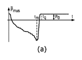
2つの連続した呼吸に関するサンプルのシミュレートされた圧力及びエアフロー波形が、図1に示されている。自発呼吸の間の又はPSVモード下の活動的な(すなわち、非鎮静状態の)患者によって働かされる努力が、実験的な患者データから生じる等価筋圧に似ているPmusプロファイルを介してシミュレートされた。図1は、胸腔内圧が、患者が活動的であるときにマイナスのスウィングを示し、人工呼吸器が呼吸装置の中への空気の送達を補助している間にプラスの振れを示すということを図示している。Paoは、患者の気道開口部における、又は、人工呼吸器のY接合部(Y−juncture)における圧力であり、一方、フロー及び体積は、外部人工呼吸器補助又は患者の活動のいずれかに起因して肺へ送達されているエアフローを示している。体積は、フローの直接積分であり、毎回の呼吸の始めにおいて、人工呼吸器においてゼロにリセットされるということが認識されることとなる。 A simulated pressure and airflow waveform of the sample for two consecutive breaths is shown in FIG. Efforts exerted by active (ie, non-sedated) patients during spontaneous breathing or under PSV mode are simulated through a Pmus profile that resembles equivalent muscle pressure resulting from experimental patient data. Was done. Figure 1 shows that intrathoracic pressure shows a negative swing when the patient is active and a positive swing while the ventilator assists in delivering air into the respiratory system. It is shown in the figure. P ao is in airway opening in a patient, or a pressure at the Y-junction of the ventilator (Y-juncture), whereas, the flow and volume, in either the external ventilator assist or patient activity It shows the airflow that is being delivered to the lungs due to it. Volume is a direct integral of the flow and will be recognized to be reset to zero on the ventilator at the beginning of each breath.
図1に示されているように、定常状態Pplは、マイナスの値を有している。それぞれの呼吸の終わりに、肺内外圧差(肺胞圧力(すなわち、内側の)マイナスPpl(すなわち、外側の)圧力として定義される)は、肺が膨張させられる(すなわち、肺胞がつぶれない)ためにプラスである必要がある。たとえば、通常の自発呼吸において、肺内外圧差は、おおよそ5cmH2Oであり、気道圧力はゼロであるので、胸膜圧力Pplは、−5cmH2Oに等しい。したがって、この呼気終末胸膜圧力Pplは、肺の機能的残気量(FRC)に関連付けられ、それは、外部(気道)呼気終末圧力(PEEP)によって影響を及ぼされる。たとえば、PSV呼吸及びPCV呼吸のPEEP値がゼロとは異なっている場合には、呼気終末胸膜圧力は、−5cmH2Oよりも大きい。 As shown in FIG. 1, the steady state P pl has a negative value. At the end of each breath, intrapulmonary external pressure difference (alveolar pressure force (i.e., inner) minus P pl (i.e., defined as an outer) pressure), lung is inflated (i.e., not crushed alveoli ) Need to be positive. For example, in normal spontaneous breathing, the intrapulmonary and external pressure difference is approximately 5 cmH 2 O and the airway pressure is zero, so the pleural pressure P pl is equal to -5 cmH 2 O. Therefore, this positive end-expiratory pleural pressure Ppl is associated with the functional residual air volume (FRC) of the lungs, which is influenced by the external (airway) positive end-expiratory pressure (PEEP). For example, if the PEEP values for PSV and PCV respiration are different from zero, the positive end-expiratory pleural pressure is greater than -5 cmH 2 O.
図2を参照すると、中心静脈と胸腔内圧波形との間の関係の定性的な実証が、Pmusとともにこれらの2つの信号をプロットすることによって取得される。すべての信号は、図1に示されている異なる呼吸タイプ(すなわち、(a)自発呼吸、(b)PSVモード、及び(c)PCVモード)に関してシミュレートされている。図2に示されているシミュレーション検討において、CVPの代わりに右心房圧(Pra)波形が示されている。臨床の現場でCVP波形を提供する静脈側カテーテル法(カテーテルは、センターラインカテーテルと称される場合がある)は、右心房の動的挙動を獲得することを目指しており、したがって、測定されるCVPは、Praの近い代用物であることが予期される。CVPセンターラインセンサーは、CVP信号情報を取得するための唯一の方式ではないということが認識されることとなる。そのような測定のための任意の手段が、CVP圧力値を取得するのに適切である。いくつかのCVPセンサーは、低圧圧力センサーであり、したがって、巨大な患者移動に起因して、それらの出力の中に歪みを起こしやすい。 With reference to FIG. 2, a qualitative demonstration of the relationship between the central vein and the intrathoracic pressure waveform is obtained by plotting these two signals together with Pmus. All signals are simulated for the different breathing types shown in FIG. 1 (ie, (a) spontaneous breathing, (b) PSV mode, and (c) PCV mode). In the simulation study shown in FIG. 2, the right atrial pressure ( Pra ) waveform is shown instead of CVP. Intravenous catheterization, which provides a CVP waveform in the clinical setting (the catheter is sometimes referred to as a centerline catheter), aims to acquire the dynamic behavior of the right atrium and is therefore measured. CVP is expected to be a close substitute for Pra. It will be recognized that the CVP centerline sensor is not the only method for acquiring CVP signal information. Any means for such measurements is suitable for obtaining CVP pressure values. Some CVP sensors are low pressure sensors and are therefore prone to distortion in their output due to huge patient movements.
呼吸活動によって引き起こされる振れに加えて、右心房圧、及び、したがって、測定されるCVP波形は、心臓血管機能に関するサイクリック振動を含む(すなわち、図2の中の黒い円形によって示されているような、心臓性信号成分)。 In addition to the runout caused by respiratory activity, the right atrial pressure, and therefore the measured CVP waveform, contains cyclic vibrations related to cardiovascular function (ie, as shown by the black circle in FIG. 2). , Cardiac signal component).
CVP信号は、測定ポイントとしての役割を果たす特定の血管又は構造体の内側又は外側のいずれかで生じるダイナミクスに起因する振れを含有している。心臓の振動は、前者のタイプのものであり、心臓及び循環装置の機能に起因するものである。それらの原因は、心臓の右側へ戻る血管系を通る血液フローの伝播にあるか、又は、収縮性の心腔(すなわち、右心房及び右心室)から起こる波の振れにある可能性がある。後者のタイプのうち、呼吸パターン(自発的であるか又は機械的に補助されているかのいずれか)は、振れを引き起こすことによって、静脈内圧力に影響を及ぼし、振れの大きさ及び方向は、外部の胸腔内圧及び血管の剛性に依存する。 The CVP signal contains runout due to dynamics occurring either inside or outside a particular vessel or structure that serves as a measurement point. The vibration of the heart is of the former type and is due to the functioning of the heart and circulatory devices. Their cause may be the propagation of blood flow through the vascular system back to the right side of the heart, or the wave swing that occurs from the contractile heart chambers (ie, right atrium and right ventricle). Of the latter types, the respiratory pattern (either spontaneous or mechanically assisted) affects intravenous pressure by causing runout, and the magnitude and direction of runout can be determined. Depends on external intrathoracic pressure and vascular stiffness.
肺の運動方程式を解くことによって呼吸装置メカニクス(たとえば、抵抗、エラスタンスなど)及び患者の呼吸筋によって働かされる努力(典型的にPmusとして定量化される)を推定するアルゴリズム、たとえば、制約付き最適化(CO)アルゴリズム及び/又はパラメトリック最適化(PO)アルゴリズムなどは、典型的に劣決定の問題の性質を克服するために、根底にある呼吸筋圧Pmus波形上の単調性制約、又は、呼吸筋圧Pmusプロファイルの形状の特定の仮定のいずれかに依存する。たとえば、CO手順において、呼吸の中のPmusプロファイルは、マイナスの単調性の領域及びプラスの単調性の領域から構成されており、マイナスの単調性の領域は、最小値を伴うポイントまで延在し、そして、プラスの単調性の領域は、一定の圧力の別の領域がその後に続くということが仮定され得る。たとえば、これらの単調性制約にしたがうサンプルのPmusプロファイルが、図3の左手側のグラフに示されている。POアプローチなどのような別の例では、Pmusは、COと同様の形態学的特質を有しているが、区分的領域が、線形(図3の右手側のグラフに示されている)、放物線、又は一定などのような、特定の事前構成されたプロファイルにしたがうということが仮定される。POは、形状、タイミング、及び大きさの観点から異なっている、可能なPmus波形の範囲にわたって探索し、気道圧力フィッティングエラーに関する限り最適な推定結果を与えるものを選択する。 Algorithms that estimate respiratory mechanics (eg, resistance, elastance, etc.) and effort exerted by the patient's respiratory muscles (typically quantified as Pmus ) by solving lung motion equations, eg, constrained Optimization (CO) and / or parametric optimization (PO) algorithms, etc., typically have monotonic constraints on the underlying respiratory muscle pressure Pmus waveform, or to overcome the nature of the problem of underdetermination. , Respiratory muscle pressure depends on any of the specific assumptions of the shape of the Pmus profile. For example, in the CO procedure, the Pmus profile in respiration consists of a negative monotonic region and a positive monotonic region, with the negative monotonic region extending to the point with the minimum value. And then it can be assumed that the positive monotonic region is followed by another region of constant pressure. For example, the Pmus profile of a sample according to these monotonic constraints is shown in the graph on the left hand side of FIG. In another example, such as the PO approach, Pmus has morphological properties similar to CO, but the piecewise region is linear (shown in the graph on the right hand side of FIG. 3). It is assumed to follow a particular preconfigured profile, such as, parabolic, or constant. The PO searches over a range of possible Pmus waveforms that differ in terms of shape, timing, and magnitude, and selects one that gives the best possible estimation results for airway pressure fitting errors.
Pmusの形態学的特質の上述の仮定は、通常の吸気努力プロファイルの認識できるほどに大きい範囲に関して満たされる。しかし、特に、病的状態において、及び/又は、不十分に構成されている人工呼吸器環境下において、筋圧がこれらの制約に準拠しないかなりの数のケースが存在している。そのようなケースは、それに限定されないが、図4に示されているものと同様に、ダブル吸気努力又は強制的な呼気努力を含むことが可能である。これらの状況下において、CO及びPOのアルゴリズム的性能は、かなり劣化することが予期される。しかし、筋圧プロファイルの全体的な形状が先験的に知られている場合には、両方のアルゴリズムは、それにしたがって修正され得、したがって、それぞれの特定の呼吸パターンに合わせられる。たとえば、ダブル吸気努力が検出される場合には、適当な単調性又は区分的な制約は、デフォルトのものを交換することが可能であり、Pmusの観点からだけでなく、呼吸装置抵抗推定値及びエラスタンス推定値の観点からも、推定結果を改善するようになっている。この目的のために、本明細書で開示されているように、CVP測定の使用を介したPmusの形状についての情報は、臨床環境の中でのCO推定技法及びPO推定技法の幅広い適用可能性を提供することが可能である。 The above assumptions about the morphological properties of Pmus are met with respect to a recognizable range of normal inspiratory effort profiles. However, there are a significant number of cases in which muscle pressure does not comply with these constraints, especially in pathological conditions and / or in a poorly constructed ventilator environment. Such cases can include, but are not limited to, double inspiratory or forced expiratory efforts, similar to those shown in FIG. Under these circumstances, the algorithmic performance of CO and PO is expected to be significantly degraded. However, if the overall shape of the muscle pressure profile is known a priori, both algorithms can be modified accordingly and are therefore tailored to each particular respiratory pattern. For example, if double inspiratory effort is detected, appropriate monotonic or piecewise constraints can replace the default ones, not only from the perspective of Pmus, but also respiratory resistance estimates. And from the viewpoint of the elastance estimate, the estimation result is improved. To this end, as disclosed herein , information about the shape of Pmus through the use of CVP measurements is widely applicable to CO and PO estimation techniques in a clinical environment. It is possible to provide sex.
別の呼吸モニタリングタスクでは、患者の呼吸活動の開始及び終了の正確な査定が、大きな挑戦であることが分かった。それぞれの機械的に補助される呼吸の、患者の要求にしたがった適正な及び同期的なトリガリング(triggering)及びサイクリングオフ(cycling off)は、呼吸仕事量のかなりの低減、人工呼吸器からのウィーニングの成功の可能性が高くなることに起因して入院の期間が短くなること、及び、したがって、医療費がより低くなることなどのような、利益をもたらす可能性がある。この目的のために、患者−人工呼吸器の非同調の正確な検出が望まれている。従来から、気道圧力及びエアフロー測定が使用され、非同調のタイプ及び重症度を決定し、次いで、医療従事者に適当な是正措置を提供し、又は、関連の人工呼吸器設定を自動的に及び最適に調節する。また、本明細書で開示されている実施形態では、胸腔内スウィングひいては呼吸努力を反映する従来の呼吸測定値(たとえば、気道圧力及びフロー)とは異なる信号をCVPが提供するので、CVP波形が、非同調を査定するために使用される。 In another respiratory monitoring task, accurate assessment of the start and end of a patient's respiratory activity proved to be a major challenge. Proper and synchronous triggering and cycling off of each mechanically assisted breathing according to the patient's requirements significantly reduces respiratory work, from the ventilator. There may be benefits such as shorter hospital stays due to a higher chance of successful weaning and therefore lower medical costs. For this purpose, accurate detection of patient-ventilator desynchronization is desired. Traditionally, airway pressure and airflow measurements have been used to determine the type and severity of out-of-tune and then provide healthcare professionals with appropriate corrective actions or automatically and relevant ventilator settings. Adjust optimally. Also, in the embodiments disclosed herein, the CVP waveform provides a signal that differs from conventional respiratory measurements (eg, airway pressure and flow) that reflect intrathoracic swing and thus respiratory effort. , Used to assess out-of-tune.
図1及び図2を参照して本明細書で説明されているものなどのようなCPシミュレーション結果によって実証されているように、胸腔内圧(Ppl)と中心静脈圧(CVP)との間の相関関係が存在している。とりわけ、換気モードを横切って筋圧波形によって表されるさまざまな呼吸パターン又は患者の状態は、異なる胸腔内圧波形を結果として生じさせ、したがって相関している中心静脈圧プロファイルを結果として生じさせる。この観察に基づいて、以下のものは、有利には、CVP信号を使用することによって、(1)COアルゴリズムの中の単調性制約を適当に修正すること、又は、POアルゴリズムの中のPmusの事前定義されたプロファイルのカテゴリーを選択すること;並びに、(2)非同調検出及び分類アルゴリズムを強化することなどのような、呼吸モニタリングタスクを実施する方式を提供する。 Between intrathoracic pressure (P pl ) and central venous pressure (CVP), as demonstrated by CP simulation results, such as those described herein with reference to FIGS. 1 and 2. There is a correlation. Among other things, the various respiratory patterns or patient conditions represented by the muscle pressure waveforms across the ventilation mode result in different intrathoracic pressure waveforms and thus a correlated central venous pressure profile. Based on this observation, the following, advantageously, by using the CVP signal, (1) appropriately modify the monotonic constraint in the CO algorithm, or Pmus in the PO algorithm. It provides a method for performing respiratory monitoring tasks, such as selecting a category of predefined profiles for; and (2) enhancing out-of-tune detection and classification algorithms.
胸腔の中の心臓及び肺の概略図が、図5に示されている。この簡単化された図では、呼吸装置(すなわち、肺)は、肺胞内圧Pal及び抵抗性経路(すなわち、気道、たとえば、気管)を有する、単一の弾性的な肺胞コンパートメント(すなわち、バルーン)によって表されている。肺胞及び心臓の両方が、胸壁(すなわち、胸腔)の中に存在しており、したがって、胸腔内圧Pplにさらされており、そして、胸腔内圧Pplは、外部気道圧力Pao及び筋圧Pmusの両方に依存している。心臓の中では、圧力Praを有する右心房に焦点が合わせられており、右心房は、胸静脈(主として、上大静脈及び下大静脈)を介して、細静脈からの血液で充填されている。右心房は、胸腔の内側に位置付けされているので、胸腔内圧Pplの変化は、右心房圧Praに影響を与え、また、その逆も同様である。これらの圧力移送は、血管組織の弾性的な特性及び血管の形状に依存するので、血管のエラスタンスの値は、どのようにこれらの変化が軽減されることとなるかということを示す。 A schematic diagram of the heart and lungs in the thoracic cavity is shown in FIG. In this simplified diagram, the respiratory system (ie, lung) has a single elastic alveolar compartment (ie, ie) with intraalveolar pressure Pal and a resistant pathway (ie, airway, eg, trachea). It is represented by a balloon). Both alveoli and heart, chest wall (i.e., chest cavity) is present in, therefore, are exposed to pleural pressure P pl, and, intrathoracic pressure P pl an external airway pressure P ao and muscle pressure It depends on both Pmus. Within the heart, the right atrium with pressure Pra is focused, and the right atrium is filled with blood from the venous veins via the thoracic veins (mainly the superior and inferior vena cava). There is. Since the right atrium is located inside the thoracic cavity, changes in intrathoracic pressure P pl affect the right atrium pressure Pra and vice versa. Since these pressure transfers depend on the elastic properties of the vascular tissue and the shape of the vascular, the value of vascular elastance indicates how these changes will be mitigated.
上記の概略図に対応する電気的な類似物が、図6に示されている。気道/肺の抵抗及びエラスタンスエレメントは、それぞれ、Raw及びELとして示されており、一方、胸壁のエラスタンスは、Ecwとして示されている。胸壁の中のエネルギー消散を考慮する追加的な抵抗Rcwは、組織の相対的に低い摩擦に起因して、省略されることが多い。たとえば、シミュレーション結果のために使用されるCPモデルは、Rcwを無視し、したがって、胸腔内圧は、Ppl=Pmus+EcwVairとして計算され、ここで、Vairは、肺の中へ送達される空気の体積であり、フローの時間積分
質量保存の原理にしたがって、中心静脈コンパートメントの体積の変化は、エラスタンスエレメントEvによって考慮されるときに、対応する空間的な場所に進入する血液フロー及び出て行く血液フローの差に等しい。したがって、以下の1階の常微分方程式(ODE)が導出され得る。
静脈の特性のうちの1つは、キャパシタンスリザーバーとして作用する、及び、かなりの量の血液体積を貯蔵する、それらの能力である。この現象の原因は、静脈の緊張の状態に依存するそれらの高いコンプライアンス値にあり、この現象は、交感神経刺激によって変更される。次いで、静脈のコンプライアンスが大きいか、又は、
Pplは、胸壁の機械的な特性(Rcwを無視する)を介して筋肉努力に関連付けられるので、等式2にしたがってCVP(t)を使用することによって、サロゲートPmus(t)信号を表現することが可能であるとみなされ得る。
したがって、等式3は、測定されるCVP(t)及びVair(t)を所与として、サロゲート呼吸筋圧Pmus,surr(t)の計算又は少なくともその波形を提供し、後者は、気道エアフローの時間積分として取得される。
Therefore,
実際の筋圧Pmus(t)と、等式3、すなわち、Pmus,surr(t)=CVP(t)−EcwVair(t)+P0を介してコンピューター計算されるサロゲート信号Pmus,surr(t)との視覚的な比較のために、PSV呼吸が焦点を合わせられる。その理由は、圧力補助換気は、患者が活動的に呼吸し、マシンによる呼吸仕事量を共有することを可能にする、共通のモードであるからである。したがって、圧力補助換気(PSV)の間に、呼吸パターンは、患者の臨床症状及び選択される人工呼吸器設定に基づいて、呼吸ごとに著しく異なるということが予期される。以前に提示されたシミュレーション結果と同様に、心肺モデルの簡単化されたバージョンが使用され、Pmus(t)及びPmus,surr(t)を発生させ、3つの異なる呼吸パターン、すなわち、(i)規則的な吸気努力(図7)、(ii)ダブル吸気努力(図8)、及び(iii)呼気努力(図9)に関して、対応する気道圧力、エアフロー、及び体積波形をシミュレートすることが可能である。CPモデルは、真のPmusだけを発生させ、次いで、CVP、気道圧力、及びエアフロー信号をシミュレート/コンピューター計算するということが認識されることとなる。これから、サロゲートPmusが、Evがおおよそゼロであるという仮定にしたがってコンピューター計算される。図7〜図9では、中心静脈圧(又は、本明細書で提示されているシミュレーション検討のケースでは、右心房圧)を介してコンピューター計算されるサロゲート筋圧(すなわち、それぞれの図の下部のグラフの中の実線)が、実際のPmus(t)(すなわち、それぞれの図の下部のグラフの中の点線)と同様に振る舞っている。1つの相違は、実際の呼吸筋圧信号の中には存在していない、より高い周波数振動がサロゲート信号の中に観察されるということであり、これらのより高い周波数振動は、鼓動を打つ心臓に起因する心臓性の振動である。心臓性の振動は、導出されるサロゲート信号Pmus,surr(t)に著しく影響を及ぼす可能性があり、したがって、それは、フィルタリングして取り除かれることが望ましい。適当なフィルタリングは、心臓血管によって誘発されるスウィングのより正確な識別のために、又は、公知の「合理的な」脈拍数の範囲(たとえば、典型的な健康な大人では毎分60〜150拍)にマッチするCVPの中の周期的なパルスとして心臓性の振動を識別するために、心電図(ECG)信号を使用することを潜在的に含むことが可能である。
The surrogate signal P mus calculated by computer via the actual muscle pressure P mus (t) and
機械的換気(MV)療法が多年にわたりICUの中で使用されてきたが、それは、依然として最適には程遠い。とりわけ、患者−人工呼吸器の非同調は、完全に鎮静状態/麻痺状態であるわけではなく、自発呼吸努力を起こすことができる、患者の中でのMVの使用に関連付けられる主要な問題のうちの1つである。人工呼吸器サイクルのタイミングが患者の呼吸サイクルのタイミングと同時ではないときに、患者−人工呼吸器の非同調が起こる。高いレベルの非同調は、呼吸仕事量の増加、MVのより長い持続期間、より高い気管切開の発生率、ウィーニング障害、より長いICU滞在の長さ及び入院、並びに、したがって、医療費の増加及び患者の予後不良に関連付けられる。 Mechanical ventilation (MV) therapy has been used in the ICU for many years, but it is still far from optimal. Among other things, patient-ventilator desynchronization is not completely sedated / paralyzed and is one of the major problems associated with the use of MV in patients who can cause spontaneous breathing efforts. It is one of. Patient-ventilator desynchronization occurs when the timing of the ventilator cycle is not simultaneous with the timing of the patient's respiratory cycle. High levels of desynchronization include increased respiratory work, longer duration of MV, higher tracheostomy incidence, weaning disorders, longer ICU stays and hospitalizations, and therefore increased medical costs. And associated with poor patient prognosis.
患者−人工呼吸器の非同調の2つのクラスが存在しており、それは、合計で5つの異なるサブタイプにさらに分割され得る。トリガリング非同調は、神経吸気期間(神経Ti)の始まりが人工呼吸器吸気期間(機械的Ti)の始まりとマッチしていない状況を表している。このクラスの中で、非同調の2つのサブタイプが識別され得る:ミストリガリング(ineffective triggering)及びオートトリガリング。サイクリングオフ非同調は、神経Tiの終わりが機械的なTiの終わりとマッチしていない状況を表している。このクラスの中で、非同調の3つのサブタイプが識別され得る:遅過ぎるサイクリングオフ(delayed cycling off);早過ぎるサイクリングオフ(early cycling off);及びダブルトリガリング。 There are two classes of patient-ventilator out-of-tune, which can be further subdivided into a total of five different subtypes. Triggering desynchronization represents a situation in which the beginning of the neural inspiratory period (nerve Ti) does not match the beginning of the ventilator inspiratory period (mechanical Ti). Within this class, two subtypes of non-tuning can be identified: infective triggering and auto-triggering. Cycling-off desynchronization represents a situation in which the end of neural Ti does not match the end of mechanical Ti. Within this class, three subtypes of non-synchronization can be identified: too late cycling off; too early cycling off; and double triggering.
本明細書で使用されているように、「ミストリガリング」という用語(及び、その変形例)は、患者が吸気努力を開始させ、それが人工呼吸器をトリガーすることができない場合の、患者−人工呼吸器の非同調を表している。 As used herein, the term "mistriggering" (and its variants) refers to a patient when the patient initiates an inspiratory effort, which is unable to trigger a ventilator. -Represents ventilator out-of-tune.
本明細書で使用されているように、「オートトリガリング」という用語(及び、その変形例)は、患者による任意の自主的な吸気努力の存在なしに人工呼吸器がトリガーされる場合の、患者−人工呼吸器の非同調を表している。 As used herein, the term "auto-triggering" (and its variants) refers to the case where the ventilator is triggered without the presence of any voluntary inspiratory effort by the patient. Represents patient-ventilator desynchronization.
本明細書で使用されているように、「遅過ぎるサイクリングオフ」という用語(及び、その変形例)は、神経Tiの終わりの後に、人工呼吸器がサイクルオフする(すなわち、圧力又はフローの能動的な送達を終了する)場合の、患者−人工呼吸器の非同調を表している。 As used herein, the term "too late cycling off" (and its variants) causes the ventilator to cycle off (ie, active pressure or flow) after the end of nerve Ti. Represents patient-ventilator desynchronization when (terminating mechanical delivery).
本明細書で使用されているように、「早過ぎるサイクリングオフ」という用語(及び、その変形例)は、神経Tiの終わりの前に、人工呼吸器がサイクルオフする(すなわち、圧力又はフローの能動的な送達を終了する)場合の、患者−人工呼吸器の非同調を表している。 As used herein, the term "premature cycling off" (and its variants) means that the ventilator cycles off (ie, pressure or flow) before the end of nerve Ti. Represents patient-ventilator desynchronization when (terminating active delivery).
本明細書で使用されているように、「ダブルトリガリング」という用語(及び、その変形例)は、人工呼吸器補助の時期尚早の終了が、同じ呼吸サイクルの中でダブル吸気サイクルが起こることを発生させる場合の、患者−人工呼吸器の非同調を表している。 As used herein, the term "double triggering" (and its variants) refers to the premature termination of ventilator assistance, but the occurrence of a double inspiratory cycle within the same respiratory cycle. Represents a patient-ventilator desynchronization in the development of.
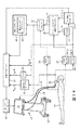
図10を参照すると、呼吸モニタリング装置10の実施形態が示されている。いくつかの実施形態では、呼吸モニタリング装置10は、機械的な人工呼吸器12を含み、機械的な人工呼吸器12は、機械的換気を患者14に送達する。したがって、呼吸モニタリング装置10は、機械的換気装置とも称される。
With reference to FIG. 10, an embodiment of the
機械的換気装置10は、機械的な人工呼吸器12を介して機械的換気を患者に提供するために使用されており、機械的な人工呼吸器12は、人工呼吸器設定にしたがって、入口空気ホース16を介して、人工呼吸器をつけている患者14に、エアフロー及び/又は圧力を送達する。吐き出された空気は、吐き出し空気ホース18を介して人工呼吸器12に戻る。Y−ピース又はT−ピース20(又は、代替的に、気管チューブ、若しくは、いくつかのケースでは、フルフェイスマスク)が、吸入の間に、入口空気ホース16の吐出端部から、人工呼吸器をつけている患者14へ、空気を連結し、また、吐き出しの間に、人工呼吸器をつけている患者14から、吐き出し空気ホース18の中へ、吐き出された空気を連結する。人工呼吸器をつけている患者14が受けている換気モード及び他の療法に応じて提供される多数の他の付属的コンポーネントは、図10に示されていない。そのような付属的コンポーネントは、図示目的として、制御されたレベルの酸素をエアフローに送達するための酸素ボトル又は他の医療グレードの酸素供給源(通常は吸入酸素濃度(FiO2)人工呼吸器設定によって制御される);入口ライン16の中へ配管された加湿器;及び、患者14に栄養を提供するための鼻腔栄養チューブなどを含む。機械的な人工呼吸器12は、ユーザーインターフェースを有しており、ユーザーインターフェースは、例示目的の例では、タッチセンサー式のディスプレイ22を含み、タッチセンサー式のディスプレイ22を介して、医師、呼吸器専門医、又は他の医療従事者は、人工呼吸器設定を可視化し、また、測定される生理学的な変数(たとえば、気道圧力及びエアフロー)並びに機械的な人工呼吸器12の動作パラメーターをモニタリングすることが可能である。追加的に又は代替的に、ユーザーインターフェースは、物理的なユーザー入力コントロール(ボタン、ダイアル、スイッチなど)、キーボード、マウス、可聴アラームデバイス、又はインジケーターライトなどを含む。
The
それに加えて、患者14は、患者のCVP信号を測定する中心静脈圧(CVP)センサー24、患者のECG信号を測定する随意的な心電図(ECG)センサー26、機械的な人工呼吸器12上の患者に関する時間の関数として気道エアフローを測定する気道フローセンサー28、及び、機械的な人工呼吸器12上の患者に関する時間の関数として気道圧力を測定する気道圧力センサー30によってモニタリングされている。患者は、他のセンサー(図示せず)、たとえば、呼吸数センサー又はSpO2センサーなどによって、モニタリングされる。例示目的のセンサー24、26、28、30のそれぞれは、より詳細に下記に説明されている。
In addition,
CVPセンサー24は、患者14のCVP信号を測定する。CVPセンサー24は、血管の中へ挿入されており、より具体的には、心臓の右心房の近くの大静脈(すなわち、下大静脈)の中へ挿入されている。有利には、右心房の中の圧力Praは、患者の胸壁と肺との間の胸膜腔の中の圧力(Ppl)と相関しており、(エアフローとともに)等式3を介して呼吸筋圧に相関しており、したがって、CVP圧力信号は、患者14の呼吸情報を抽出するために使用され得る。それを行うために、呼吸モニタリング装置10は、少なくとも1つのプロセッサーを含み、少なくとも1つのプロセッサーは、患者に関する呼吸情報を発生させるようにプログラムされている。たとえば、例示目的の少なくとも1つのプロセッサーは、積分プロセッサー32、呼吸検出プロセッサー34、呼吸ごとのサロゲート筋圧プロセッサー36、フィルタリングプロセッサー38、検出プロセッサー40、呼吸ごとの呼吸パラメーター/変数を推定するプロセッサー42、及びWOB計算機44を含む。
The
積分プロセッサー32は、空気体積
Pmus,surr(t)=CVP(t)−EcwVair(t)+P0
ここで、tは、呼吸間隔[0,Ttot]に属しており、CVP(t)は、CVP信号を示しており、Ecwは、胸壁エラスタンスを示しており、Vairは、積分プロセッサー32によってコンピューター計算される肺空気体積を示しており、P0は、定数に対応している。バイアス項P0の決定は、重要ではない。その理由は、真の筋圧信号が、ゼロ値から開始し、ゼロ値で終了するために、常にシフトさせられるからである。それに加えて、(たとえば、単調増加領域若しくは単調減少領域、ダブルピーク、又は、他のそのような動的構造ダイナミクスを識別するために)Pmus波形形状が関心対象である用途では、P0値の選択は、重要性を持たない。
The
P mus, surr (t) = CVP (t) -E cw V air (t) + P 0
Here, t belongs to the breath interval [0, T tot], CVP (t) shows the CVP signal, E cw shows a chest wall elastance, V air is integrated processor It shows the lung air volume calculated by 32, where P 0 corresponds to a constant. The determination of the bias term P 0 is not critical. The reason is that the true muscle pressure signal is always shifted to start at zero and end at zero. In addition, in applications P mus waveform (e.g., monotonically increasing region or monotone decreasing area, double peak or, in order to identify other such dynamic structural dynamics) is of interest, P 0 value The choice of is of no importance.
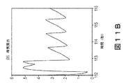
次いで、呼吸ごとのPmus,surr信号は、フィルタリングプロセッサー38へ送信される。また、この時点において、セグメント化されたCVP及び/又はPmus,surr信号は、呼吸モニタリング装置10のディスプレイ22上に表示され得る。図11Aは、ダブル吸気努力を伴う呼吸に関してディスプレイ22上に表示されているセグメント化されたCVP信号を示しており、一方、図11Bは、呼気努力を伴う呼吸に関してディスプレイ22上に表示されているセグメント化されたCVP信号を示している。図11A及び図11Bの両方において、右心房圧Pra(CVPによって適切に表されている)は、呼吸検出器34によって与えられる時間サンプルによってセグメント化されている。
The Pmus, surr signal for each breath is then transmitted to the
フィルタリングプロセッサー38は、呼吸ごとのサロゲート筋圧プロセッサー36から、呼吸ごとのPmus,surr信号を受信するようにプログラムされている。いくつかの実施形態では、ECGセンサー26が含まれているときに、フィルタリングプロセッサー38は、ECGセンサー26からECG信号を受信するようにプログラムされており、また、呼吸検出器34の出力にしたがって、ECG信号を呼吸間隔へとセグメント化するようにプログラムされている。フィルタリングプロセッサー38は、受信されたPmus,surr信号をフィルタリングし、信号の心臓の活動成分を除去するようにプログラムされている。いくつかの実施形態では、ECGセンサー26が使用されていないときに、フィルタリングプロセッサー38は、患者14の心臓の活動を示すデータをPmus,surr信号から除去するようにプログラムされている。たとえば、Pmus,surr信号の中の心臓性の振動は、本来的に、呼吸数よりもはるかに高い周波数によって、実質的に周期的となることが予期される。したがって、フィルタリングプロセッサー38は、Pmus,surr信号のどの部分とフィルタリングして取り除くかということを決定することが可能である。別の例では、ECGセンサー26が使用されるときに、フィルタリングプロセッサー38は、受信されたECG信号を使用し、患者の心臓の活動を示すPmus,surr信号の部分(すなわち、「除去する」)をフィルタリングするようなプログラムされている。異なる実施形態では、心臓性の成分が、最初にCVP信号からフィルタリングされて除去され、サロゲート筋圧信号のコンピューター計算がその後に続く。
The
この時点において、フィルタリングされたPmus,surr信号は、ディスプレイ22上に表示され得る。図12Aは、ダブル吸気努力を伴う呼吸に関してディスプレイ22上に表示されるサロゲートPmus信号を示しており、一方、図12Bは、呼気努力を伴う呼吸に関してディスプレイ22上に表示されているサロゲートPmus信号を示している。図12A及び図12Bの両方において、等式3によってコンピューター計算されたPmus,surr信号は、サロゲート信号の心臓成分を除去するためにフィルタリングされている。たとえば、図12Aの中の約421秒、422秒、及び423秒における、小さいピークが、フィルタリングの後に残っている残留心臓性信号である。
At this point, the filtered Pmus, surr signal can be displayed on the
患者14に関して発生させられた呼吸情報は、(1)セグメント化及びフィルタリングされたCVP信号に等しいサロゲート胸腔内圧信号(すなわち、セグメント化及びフィルタリングされたCVP信号値、等式2を参照);(2)セグメント化されたCVP信号からそれぞれの呼吸間隔に関して決定されるフィルタリングされるサロゲート呼吸筋圧波形(すなわち、Pmus,surr、等式3を参照);及び、それに類するもの(たとえば、WoB又はPoB)を含むことが可能であるということが認識されることとなる。発生させられる呼吸情報のそれぞれは、いくつかの実施形態では、ディスプレイ22上に表示され得る。
Respiratory information generated for
いくつかの実施形態では、検出プロセッサー40は、計算されたサロゲートPmus信号の特徴を検出又は抽出し、信号の形状を決定するようにプログラムされる。たとえば、検出プロセッサー40は、セグメント化及びフィルタリングされたPmus,surr信号の中に複数のピーク46及び48を検出するようにプログラムされている。検出されたピーク46及び48から、検出プロセッサーは、ピークによって境界を定められた時間間隔にわたって、呼吸情報(たとえば、CVP(t)及びPmus,surr(t)など)セグメントを発生させるようにプログラムされている。ピーク46は、プラスのピークに対応しており、ピーク48は、マイナスのピークに対応している。検出プロセッサー40は、プラスのピーク46、マイナスのピーク48、並びに、ピーク同士の間のセグメントの単調性、すなわち、マイナスの単調性50を有するセグメント、プラスの単調性52を有するセグメント、及び、一定の値54を有するセグメントを識別するようにプログラムされている。サロゲートPmus信号の形状は、呼吸ごとの呼吸パラメーター/変数を推定するプロセッサー42の中に統合されている対応するCOアルゴリズム及び/又はPOアルゴリズムの中の制約又はパラメーターを変更するために使用され得る。たとえば、筋圧プロファイルの形状の生理学的な知識は、Pmus(t)上の領域的な制約の形態で、呼吸パラメーター/変数を推定するプロセッサー42の中に注入され得る。COアプローチでは、そのような単調な領域は、不等式及び等式のセットで表現され、所望の呼吸器系パラメーター及びPmus(t)プロファイルが、制約付き最適化問題によって推定され、制約付き最適化問題の2次費用関数は、上述の領域的な制約を受ける。異なる態様では、POアプローチは、簡単であるが現実的な数学的テンプレートを用い、単一の呼吸にわたって線形の区分的にパラメーター化されたPmus(t)を表現する。WOB計算機44は、推定器42からの呼吸ごとの推定されたPmus(t)を処理するようにプログラムされており、また、等式
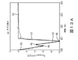
たとえば、検出プロセッサー40は、任意の適切なピーク検出ハードウェア(たとえば、ダイオード及びコンデンサーを備えたピーク検出器回路)又はソフトウェア(たとえば、Matched Filtration with Experimental Noise Determinationアルゴリズム、ベクトル化ピーク検出アルゴリズム、最小二乗法カーブフィッティングアルゴリズム、最適化ピーク検出アルゴリズム、又は微分ベースのアルゴリズムなど)を含むことが可能である。本明細書で説明されている例示目的の実施形態では、検出プロセッサー40は、微分ベースのモジュール56を使用し、Pmus,surr(t)−対−時間信号のピークを検出することが可能である。また、微分ベースのモジュール56は、信号処理プロセスのための任意の適切なアルゴリズム(たとえば、フィルタリング、信号雑音比低減、及びデータスムージングなど)を含むということが認識されることとなる。より詳細に下記に説明されているように、微分ベースのモジュール56は、より詳細に下記に説明されているように、ピーク検出読み値に基づいて、呼吸パターンの中の1つ又は複数の異常を識別する。微分ベースのモジュール56は、ピーク値46、48(たとえば、より詳細に下記に説明されているように、Pmus,surr(t)−対−時間信号の「y軸」値)、及び、これらのピークが起こる、関連の時間値(たとえば、「x軸」値)を検出する。ピーク46、48から、Pmus,surr信号の形状が決定され得る。Pmus,surr(t)信号に関する明確な単調性の検出されたセグメントが、ダブル吸気努力を伴う呼吸(図13A)及び呼気努力を伴う呼吸(図13B)に関して、図13A及び図13Bに示されている。
For example, the
図14は、機械的換気装置10’の別の実施形態を示しており、そこでは、少なくとも部分的にCVP測定から導出される呼吸情報が使用され、開ループの人工呼吸器制御ガイダンス、又は、自動化された閉ループの人工呼吸器制御を提供する。機械的換気装置10’は、下記に説明されているようなものを除いて、図10の機械的換気装置10と実質的に同一に構成され得る。
FIG. 14 shows another embodiment of the mechanical ventilator 10', in which respiratory information derived from CVP measurements is used, at least in part, with open-loop ventilator control guidance, or. Provides automated closed-loop ventilator control. The mechanical ventilator 10'can be configured substantially identical to the
機械的換気装置10’は、上記に説明されているように、機械的な人工呼吸器12(及び、関連のコンポーネント)、CVPセンサー24、随意的なECGセンサー26、エアフローセンサー28、気道圧力センサー30、積分プロセッサー32、呼吸検出プロセッサー34、呼吸ごとのサロゲート筋圧プロセッサー36、フィルタリングプロセッサー38、検出プロセッサー40、呼吸ごとの呼吸パラメーター/変数を推定するプロセッサー42、及びWOB計算機44、並びにディスプレイ22を含む。また、機械的換気装置10’は、分類プロセッサー58を含み、分類プロセッサー58は、より詳細に下記に説明されている。
The mechanical ventilator 10'is a mechanical ventilator 12 (and related components), a
上記に説明されているように、積分プロセッサー32は、エアフローの時間積分をコンピューター計算し、また、呼吸検出プロセッサー34は、吸気の開始を識別し、それぞれの呼吸に関して呼吸間隔[0,Ttot]を定義する。呼吸ごとのサロゲート筋圧プロセッサー36は、CVPセンサー24からCVP信号を受け入れ、積分器32から空気体積を受け入れ、呼吸検出プロセッサー34から呼吸間隔を受け入れるようにプログラムされている。プロセッサー36は、上記に説明されているように、呼吸間隔時間インスタンスを使用して、CVP及び体積信号をセグメント化し、呼吸ごとのサロゲート筋圧信号をコンピューター計算するようにプログラムされている。
As described above, the
呼吸ごとのPmus,surr信号は、フィルタリングプロセッサー38に送信され、フィルタリングプロセッサー38において、それは、上記に説明されているようにフィルタリングされる。また、ECGセンサー26からの随意的なECG信号が、フィルタリングプロセッサー38によって使用され、フィルタリングプロセスを改善することが可能である。次いで、フィルタリングされた呼吸ごとのPmus,surr信号は、検出プロセッサー40によって処理され、そのピーク46、48を決定する。これらのピーク検出された信号は、ディスプレイ22上に表示され得る。また、ピーク検出された信号は、分類プロセッサー58に送信される。
The per-breathing Pmus, surr signal is transmitted to the
分類プロセッサー58は、非同調なし;ミストリガリング;オートトリガリング;遅過ぎるサイクリングオフ;早過ぎるサイクリングオフ;及びダブルトリガリングのうちの少なくとも1つにしたがって、抽出された(すなわち、ピーク検出された)Pmus,surr信号、気道圧力、エアフロー、及び体積信号に基づいて、呼吸ごとのベースで非同調を分類するようにプログラムされている。図15は、それぞれのタイプの非同調に関して、表示された信号の例を示している。分類プロセッサー58は、人工ニューラルネットワーク、ロジスティック回帰アルゴリズム、及びベイズ分類アルゴリズムなどとして構成され得る。
図14に戻って参照すると、分類プロセッサー58は、検出プロセッサー40の微分ベースのモジュール56から、ピーク及び単調性検出読み値を受け取る。これらのピーク及び単調性検出読み値から、分類プロセッサー58は、任意の異常な/正常でない呼吸を示し、患者−換気非同調のタイプ(たとえば、ミストリガリング;オートトリガリング;遅過ぎるサイクリングオフ;早過ぎるサイクリングオフ;及びダブルトリガリング)を決定する。次いで、分類プロセッサー58は、非同調について「フラッグ」を立て、より詳細に下記に説明されているように、対応するインディケーションを非同調のタイプに割り当てることが可能である。次いで、インディケーションは、ディスプレイ22に送信され、ディスプレイ22上に表示される。
Returning to FIG. 14, the
次いで、分類プロセッサー58は、気道圧力、エアフロー、及び体積波形とともに、検出プロセッサー40からの抽出されたサロゲート筋圧信号を分析し、非同調のタイプを決定する。図13A及び図13Bに示されている例では、フィルタリングされたサロゲート筋圧信号は、複数のピーク(プラスのピーク46、又はマイナスのピーク48のいずれか)、及び、明確な単調性の異なる領域(マイナスの領域50、プラスの領域52、又は、一定の値の領域54など)を含む。「テンプレート」として図15に示されている信号を使用することによって、分類プロセッサー58は、テンプレートを気道圧力及びエアフローの実際の測定された信号と比較し、及び/又は、サロゲート筋圧信号の中のピーク46、48及び明確な単調性のセグメント50、52、54の位置を使用し、非同調のタイプを決定することが可能である。マイナス及びプラスのピーク46及び48(上記に説明されている)の位置決めに起因して、分類プロセッサー58は、根底にある筋圧努力がダブル吸気努力(図13A)又は呼気努力(図13B)を受けているということを決定する。次いで、分類プロセッサー58は、たとえば、図13Aに関して可能性のあるダブルトリガリング非同調、及び、図13Bに関して遅過ぎるサイクリングオフ非同調など、非同調タイプについてフラッグを立て、非同調のインディケーション(すなわち、数値)をディスプレイコンポーネント22に送り、ディスプレイコンポーネント22において、それが、医療専門家(たとえば、看護師及び医者など)のために表示される。
The
他の実施形態では、非同調が検出されるときに、Pmus,surr(t)のインディケーション及び/又は表示された信号は、非同調が起こっているということを医療専門家に伝える。分類プロセッサー58は、非同調を是正するために機械的な人工呼吸器12の設定を調節するという推奨を医療専門家に提案するようにさらにプログラムされている。推奨は、ディスプレイ22上に表示される。次いで、医療専門家は、非同調がもはや起こらないように、人工呼吸器12の設定を調節することが可能である。このように、機械的換気装置10’は、開ループの装置である。それぞれのタイプの非同調に関して適切な是正措置の概要は、下記の表1に説明されている。
In other embodiments, when out-of-tune is detected, the indication and / or displayed signal of Pmus, surr (t) informs the medical professional that the out-of-tune is occurring. The
さらなる実施形態では、機械的換気装置10’は、非同調を是正するために機械的な人工呼吸器12の設定を自動的に調節するようにさらにプログラムされている。それを行うために、機械的換気装置10’は、閉ループコントローラー60を含む。いくつかの実施形態では、閉ループコントローラー60は、呼吸力コントローラー又は呼吸仕事量コントローラーとして構成され得る。そのようなケースでは、呼吸ごとの呼吸パラメーター/変数を推定するプロセッサー42、及び、WOB/POB計算機44が、コントローラー60の中へ一体化されている。閉ループコントローラー60は、42から推定されるPmus(t)とエアフローとの積の時間積分によって、患者の呼吸力(又は、呼吸仕事量)を計算するようにプログラムされており、また、患者の自発呼吸努力を最適に補助するために、実際の呼吸力又は呼吸仕事量と所望の呼吸力又は呼吸仕事量との間の差に基づいて、人工呼吸器設定を調節するようにプログラムされている。そのような閉ループコントローラーは、米国特許出願公開第2015/0059754号明細書に説明されており、その文献は、その全体が本明細書に組み込まれている。本明細書で開示されている実施形態では、分類プロセッサー58によるインディケーション出力は、また、閉ループの人工呼吸器コントローラー60への入力である。インディケーションが呼吸非同調を示す場合には、次いで、閉ループ人工呼吸器コントローラー60は、たとえば、現在の人工呼吸器設定を開ループの方式で維持すること、又は、表1に列挙されている推奨に基づいて、検出された非同期的な条件に基づいて人工呼吸器設定を調節することなど、適当なアクションをとることが可能である。他の実施形態では、コントローラー60は、複数の入力及び複数の出力(MIMO)のコントローラーであることが可能であり、それは、WOB/POB値の他に、SpO2、呼気終末CO2、及び/又は、平均動脈血圧値などのような、追加的な生理学的な変数を受け入れ、したがって、圧力補助レベル、呼気終末圧力、トリガリング感度及びサイクリングオフ感度、並びに/又は、供給される空気の中の酸素の割合のような、複数の人工呼吸器設定を調節する。
In a further embodiment, the mechanical ventilator 10'is further programmed to automatically adjust the
また、本明細書で説明されているさまざまな信号及び値は、通信ネットワーク(たとえば、ワイヤレスネットワーク、ローカルエリアネットワーク、ワイドエリアネットワーク、パーソナルエリアネットワーク、及びBLUETOOTH(登録商標)など)を介して、さまざまなプロセッサー36、38、40、58、及び、コンポーネント12、22、42、44、60に通信され得るということが理解されることとなる。代替的に、コンポーネント36、38、40、42、44、58、及びコントローラー60は、機械的な人工呼吸器12(たとえば、人工呼吸器12のマイクロプロセッサー又はマイクロコントローラーの上で実行する)の中へ埋め込まれ、そのケースでは、センサー24、26、28、30からのデータが、人工呼吸器12によって収集され、したがって、コンポーネント36、38、40、42、44、58、及びコントローラー60に利用可能である。別の企図される実施形態では、プロセッサーのアルゴリズムは、患者モニター(図示せず)のマイクロプロセッサー上に実装されており、患者モニターは、心拍数、呼吸速度、又は血液圧力などのようなバイタルサインを表示し、これらのプロセッサー36、38、40、58、及びコンポーネント42、44の出力が、患者モニターディスプレイコンポーネント上に適切に表示される。
Also, the various signals and values described herein vary via communication networks such as wireless networks, local area networks, wide area networks, personal area networks, and BLUETOOTH®. It will be understood that
図16は、異常な呼吸パターンのケースにおいて呼吸パラメーター推定を改善する方法100を示している。方法100は、対応するセンサー24、26、28、30から、患者のCVP信号、気道圧力信号、エアフロー信号、及びECG信号を受信すること(102)を有する。患者のそれぞれの呼吸に関して、受信された信号がセグメント化される(104)。患者によって発生させられる呼吸筋圧に関するサロゲート信号が、それぞれのセグメント化された呼吸に関して計算される(106)。患者の心臓の活動を示すデータが、サロゲート筋圧信号からフィルタリングされる(108)。フィルタリングされた信号の中のピークが抽出される(110)。プラスの単調性の領域、マイナスの単調性の領域、及び、一定の値の領域が、フィルタリングされた信号上に定義される(112)。COアルゴリズム及びPOアルゴリズムの中の根底にある筋圧プロファイルの形状のデフォルト仮定が修正される(114)。患者の呼吸筋努力及び呼吸器系のパラメーターのより正確な推定が提供される(116)。
FIG. 16 shows a
図17は、患者−人工呼吸器の非同調イベントを検出すると、選択された人工呼吸器設定に関して是正措置を提案するか、又は、自動的に実施する方法200を示している。方法200は、対応するセンサー24、26、28、30から、患者のCVP信号、気道圧力信号、エアフロー信号、及びECG信号を受信すること(202)を有する。患者のそれぞれの呼吸に関して、受信された信号がセグメント化される(204)。患者によって発生させられる呼吸筋圧に関するサロゲート信号が、それぞれのセグメント化された呼吸に関して計算される(206)。患者の心臓の活動を示すデータが、サロゲート筋圧信号からフィルタリングされる(208)。フィルタリングされた信号の中のピークが抽出される(210)。プラスの単調性の領域、マイナスの単調性の領域、及び、一定の値の領域が、フィルタリングされた信号上に定義される(212)。非同調が、筋圧信号及び測定された気道圧力信号及びエアフロー信号の全体的な形状に基づいて分類される(214)。人工呼吸器の設定を調節するという推奨が提案されるか、又は、人工呼吸器の設定が自動的に調節される(216)。
FIG. 17
さまざまなデータ処理コンポーネント36、38、40、42、44、58、及びコントローラー60は、ファームウェア又はソフトウェアによってプログラムされたマイクロプロセッサーとして適切に実装され、開示されている動作を実施する。いくつかの実施形態では、マイクロプロセッサーは、機械的な人工呼吸器12と一体になっており、データ処理が人工呼吸器12によって直接的に実施されるようになっている。他の実施形態では、マイクロプロセッサーは、機械的な人工呼吸器12から分離しており、たとえば、デスクトップコンピューターのマイクロプロセッサーである。また、機械的な人工呼吸器装置のさまざまなデータ処理コンポーネント36、38、40、42、44、58、及びコントローラー60は、(たとえば、上記に説明されているように)マイクロプロセッサーによって読み取り可能な及び実行可能なインストラクションを記憶している非一時的なストレージ媒体として実装され、開示されている動作を実装する。非一時的なストレージ媒体は、たとえば、リードオンリーメモリー(ROM)、プログラマブルリードオンリーメモリー(PROM)、フラッシュメモリー、又は、人工呼吸器12のためのファームウェアの他のリポジトリを含む。追加的に又は代替的に、非一時的なストレージ媒体は、コンピューターハードドライブ(コンピューター実装される実施形態に関して適切である)、光ディスク(たとえば、そのようなコンピューター上のインストールのためのもの)、又は、ネットワークサーバーデータストレージ(たとえば、RAIDアレイ)(人工呼吸器12又はコンピューターが、そこから、インターネット又は別の電子的なデータネットワークを介して、装置ソフトウェア又はファームウェアをダウンロードすることができる)などを含む。
The various
本発明は、好適な実施形態を参照して説明されてきた。先行する詳細な説明を読んで理解すると、修正例及び代替例が当業者に思い付く。本発明は、添付の特許請求の範囲又はその均等物の範囲に入る限り、すべてのそのような修正例及び代替例を含むものとして考えられるということが意図されている。 The present invention has been described with reference to preferred embodiments. After reading and understanding the detailed description that precedes, one of ordinary skill in the art will come up with modifications and alternatives. The present invention is intended to be considered as including all such modifications and alternatives, as long as they fall within the appended claims or equivalents thereof.
Claims (12)
患者の中心静脈圧(CVP)信号を測定する中心静脈圧センサーと、
機械的な人工呼吸器上の前記患者に関して、時間の関数として気道エアフローを測定する少なくとも1つの気道センサーと、
少なくとも1つのプロセッサーであって、前記少なくとも1つのプロセッサーは、
検出された呼吸間隔に基づいて前記CVP信号をセグメント化すること、
セグメント化された前記CVP信号及び時間の関数としての前記気道エアフローからサロゲート呼吸筋圧信号を計算すること、並びに、
前記サロゲート呼吸筋圧信号をフィルタリングし、前記サロゲート呼吸筋圧信号の心臓の活動成分を除去すること
を含む動作によって、前記患者に関する呼吸情報を発生させるようにプログラムされている、少なくとも1つのプロセッサーと、を含み、
前記少なくとも1つのプロセッサーは、
以下の等式から時間の関数としてサロゲート呼吸筋圧信号を計算するようにプログラムされており、
P mus,surr (t)=CVP(t)−E cw V air (t)+P 0 ;
ここで、P mus,surr (t)は、サロゲート呼吸筋圧信号を示しており、CVP(t)は、前記CVP信号を示しており、E cw は、胸壁エラスタンスを示しており、V air は、時間の関数とした前記気道エアフローの積分としてコンピューター計算された肺空気体積を示しており、P 0 は、定数を示している、
呼吸モニタリング装置。 It is a respiration monitoring device, and the respiration monitoring device is
A central venous pressure sensor that measures the patient's central venous pressure (CVP) signal,
With respect to the patient on a mechanical ventilator, at least one airway sensor that measures airway airflow as a function of time,
At least one processor, said at least one processor
Segmenting the CVP signal based on the detected breathing interval,
Computing the surrogate respiratory muscle pressure signal from the segmented CVP signal and the airway airflow as a function of time, and
Filtering the surrogate respiratory muscles pressure signal, the operation including removing the activity components of the heart of the surrogate respiratory muscles pressure signal, is programmed to generate a respiration information for the previous SL patient, at least one processor and, only including,
The at least one processor
It is programmed to calculate the surrogate respiratory muscle pressure signal as a function of time from the following equation:
P mus, surr (t) = CVP (t) -E cw V air (t) + P 0 ;
Here, P mus, surr (t) indicates a surrogate respiratory muscle pressure signal, CVP (t) indicates the CVP signal, E cw indicates a chest wall elastance, and a volume. Indicates the lung air volume calculated by computer as the integral of the airway airflow as a function of time, and P 0 indicates a constant.
Respiratory monitoring device.
セグメント化及びフィルタリングされた前記CVP信号から決定されるサロゲート胸腔内圧信号と、
セグメント化及びフィルタリングされた前記CVP信号、並びに、空気体積信号を決定するために積分される測定されたエアフロー信号から、それぞれの呼吸間隔に関して決定されるサロゲート呼吸筋圧波形と、のうちの少なくとも1つを含む、
請求項1に記載の呼吸モニタリング装置。 The generated breathing information is
A surrogate intrathoracic pressure signal determined from the segmented and filtered CVP signal,
At least one of the surrogate respiratory muscle pressure waveforms determined for each respiratory interval from the segmented and filtered CVP signal and the measured airflow signal integrated to determine the air volume signal. Including one
The respiratory monitoring device according to claim 1.
前記少なくとも1つのプロセッサーは、前記ECGセンサーから受信される前記ECG信号を使用して、前記フィルタリングを実施するようにプログラムされている、
請求項1又は2に記載の呼吸モニタリング装置。 The respiratory monitoring device further includes an ECG sensor that measures an electrocardiogram (ECG) signal.
The at least one processor is programmed to perform the filtering using the ECG signal received from the ECG sensor.
The respiratory monitoring device according to claim 1 or 2.
前記少なくとも1つのプロセッサーは、
前記機械的な人工呼吸器から、前記患者のそれぞれの呼吸に関して、時間の関数として吸入マークのスタートを受け取るように、及び、
前記吸入マークのスタートから前記患者の呼吸間隔を決定するように、さらにプログラムされている、
請求項1〜3のいずれか一項に記載の呼吸モニタリング装置。 The respiratory monitoring device further comprises the mechanical ventilator that delivers mechanical ventilation to the patient.
The at least one processor
From the mechanical ventilator to receive the start of the inhalation mark as a function of time for each breath of the patient, and
Further programmed to determine the patient's breathing interval from the start of the inhalation mark,
The respiratory monitoring device according to any one of claims 1 to 3.
セグメント化及びフィルタリングされた前記サロゲート呼吸筋圧信号の中に複数のピークを検出するように、及び、
前記ピークによって境界を定められた時間間隔にわたって、呼吸筋圧波形セグメントを含む呼吸筋圧波形を含む前記呼吸情報を発生させるように、さらにプログラムされている、
請求項1〜4のいずれか一項に記載の呼吸モニタリング装置。 The at least one processor
To detect multiple peaks in the segmented and filtered surrogate respiratory muscle pressure signal, and
It is further programmed to generate the respiratory information, including the respiratory muscle pressure waveform, including the respiratory muscle pressure waveform segment, over a time interval bounded by the peak.
The respiratory monitoring device according to any one of claims 1 to 4.
ピーク検出されたサロゲート呼吸筋圧信号に基づいて、前記機械的な人工呼吸器の制約付き最適化アルゴリズム及び/又はパラメトリック最適化アルゴリズムの設定を更新するように、さらにプログラムされている、
請求項5に記載の呼吸モニタリング装置。 The at least one processor
It is further programmed to update the settings of the mechanical ventilator constrained optimization algorithm and / or parametric optimization algorithm based on the peak-detected surrogate respiratory muscle pressure signal.
The respiratory monitoring device according to claim 5.
機械的な人工呼吸器と、
前記機械的な人工呼吸器上の患者に関して、時間の関数として気道圧力及びエアフローを測定する少なくとも1つの気道センサーと、
少なくとも1つのプロセッサーであって、前記少なくとも1つのプロセッサーは、
中心静脈圧センサーから中心静脈圧信号を受信するようにプログラムされ、
前記少なくとも1つの気道センサーから、前記患者に関して時間の関数としてエアフロー信号を受信するようにプログラムされ、
前記患者のそれぞれの呼吸に関して、時間の関数としてサロゲート呼吸筋圧信号を計算するようにプログラムされ、
前記患者の心臓の活動を示すデータを前記サロゲート呼吸筋圧信号からフィルタリングすること、
前記サロゲート呼吸筋圧信号の形状を決定すること、並びに、
形状検出された信号に基づいて、前記機械的な人工呼吸器の制約付き最適化アルゴリズム及び/又はパラメトリック最適化アルゴリズムの設定を更新すること
を含む動作によって、前記サロゲート呼吸筋圧信号から少なくとも1つの呼吸特質を抽出するようにプログラムされている、少なくとも1つのプロセッサーと、を含み、
前記少なくとも1つのプロセッサーは、
受信された前記中心静脈圧信号及び空気体積信号から、前記機械的な人工呼吸器上の前記患者によって発生させられるサロゲート呼吸筋圧信号を時間の関数として計算するように、さらにプログラムされており、
前記少なくとも1つのプロセッサーは、
以下の等式から、前記機械的な人工呼吸器上の前記患者によって発生させられるサロゲート呼吸筋圧信号を時間の関数として計算するようにさらにプログラムされており、
P mus,surr (t)=CVP(t)−E cw V air (t)+P 0 ;
ここで、P mus,surr (t)は、サロゲート呼吸筋圧信号に対応しており、CVPは、中心静脈圧に対応しており、E cw は、胸壁のエラスタンスに対応しており、V air は、時間の関数とした前記エアフローの積分としてコンピューター計算された肺空気体積を示しており、P 0 は、定数に対応しており、
また、前記サロゲート呼吸筋圧信号の計算された値をディスプレイ上に表示するようにさらにプログラムされている、
機械的換気装置。 It is a mechanical ventilation device, and the mechanical ventilation device is
With a mechanical ventilator,
With respect to the patient on the mechanical ventilator, at least one airway sensor that measures airway pressure and airflow as a function of time.
At least one processor, said at least one processor
Programmed to receive a central venous pressure signal from the central venous pressure sensor,
Programmed to receive airflow signals from the at least one airway sensor as a function of time with respect to the patient.
Programmed to calculate surrogate respiratory muscle pressure signals as a function of time for each of the patients' breaths
Filtering data showing the patient's cardiac activity from the surrogate respiratory muscle pressure signal,
Determining the shape of the surrogate respiratory muscle pressure signal, and
At least one from the surrogate respiratory muscle pressure signal by an action involving updating the settings of the constrained optimization algorithm and / or parametric optimization algorithm of the mechanical ventilator based on the shape-detected signal. is programmed to extract a respiratory characteristics, and at least one processor, only including,
The at least one processor
It is further programmed to calculate the surrogate respiratory muscle pressure signal generated by the patient on the mechanical ventilator as a function of time from the received central venous pressure signal and air volume signal.
The at least one processor
From the following equation, the surrogate respiratory muscle pressure signal generated by the patient on the mechanical ventilator is further programmed to be calculated as a function of time.
P mus, surr (t) = CVP (t) -E cw V air (t) + P 0 ;
Here, P mus, surr (t) correspond to the surrogate respiratory muscle pressure signal, CVP corresponds to the central venous pressure, E cw corresponds to the elastance of the chest wall, and V. air indicates the lung air volume calculated by a computer as an integral of the air flow as a function of time, and P 0 corresponds to a constant.
It is also further programmed to display the calculated value of the surrogate respiratory muscle pressure signal on the display.
Mechanical ventilation system.
前記患者の心臓の活動を示すデータを測定する心電図(ECG)センサーをさらに含み、
前記少なくとも1つのプロセッサーは、検出された呼吸間隔に基づいて前記中心静脈圧信号をセグメント化し、前記ECGセンサーから受信される前記心臓のデータを使用して、前記セグメント化された前記中心静脈圧信号から、前記患者の心臓の活動を示すデータをフィルタリングするようにさらにプログラムされている、
請求項7に記載の機械的換気装置。 The mechanical ventilation device is
An electrocardiogram (ECG) sensor that measures data indicating the patient's heart activity is further included.
Wherein the at least one processor to segment the central venous pressure signal based on the detected breath interval, using data of the heart that is received from the ECG sensor, the segmented the central venous pressure signal Is further programmed to filter data indicating the patient's cardiac activity.
The mechanical ventilation device according to claim 7.
前記機械的な人工呼吸器から、前記患者のそれぞれの呼吸に関して、時間の関数として吸入マークのスタートを受け取るように、及び、前記患者のそれぞれの呼吸に関して、時間の関数として吐き出しマークのスタートを受け取るように、並びに、
前記患者のそれぞれの呼吸を決定するために、受け取られた前記マーク及び前記エアフロー信号を時間の関数としてセグメント化することによって、前記吸入マークのスタート及び前記吐き出しマークのスタートから、時間の関数として前記患者のそれぞれの呼吸の持続期間を決定するように、さらにプログラムされている、
請求項7又は8に記載の機械的換気装置。 The at least one processor
From the mechanical ventilator, receive the start of the inhalation mark as a function of time for each breath of the patient, and receive the start of the exhalation mark as a function of time for each breath of the patient. So, as well,
From the start of the inhalation mark and the start of the exhalation mark, said as a function of time, by segmenting the received mark and the airflow signal as a function of time to determine each breath of the patient. Further programmed to determine the duration of each breath of the patient,
The mechanical ventilation device according to claim 7 or 8.
前記フィルタリングされたサロゲート呼吸筋圧信号の中の複数のピークを抽出するようにさらにプログラムされており、前記ピークは、前記フィルタリングされたサロゲート呼吸筋圧信号の形状に対応している、
請求項7〜9のいずれか一項に記載の機械的換気装置。 The at least one processor
It is further programmed to extract a plurality of peaks in the filtered surrogate respiratory muscle pressure signal, the peaks corresponding to the shape of the filtered surrogate respiratory muscle pressure signal.
The mechanical ventilation device according to any one of claims 7 to 9.
ミストリガリング;
オートトリガリング;
遅過ぎるサイクリングオフ;
早過ぎるサイクリングオフ;及び、
ダブルトリガリング
のうちの少なくとも1つにしたがって、抽出された前記サロゲート呼吸筋圧信号の非同調を分類するようにプログラムされた分類プロセッサーをさらに含む、
請求項7〜10のいずれか一項に記載の機械的換気装置。 No out-of-tune;
Mistriggering;
Auto triggering;
Cycling off too late;
Cycling off too early; and
Further comprising a classification processor programmed to classify the out-of-sync of the extracted surrogate respiratory muscle pressure signal according to at least one of the double triggering.
The mechanical ventilation device according to any one of claims 7 to 10.
前記非同調を是正するために前記機械的な人工呼吸器の設定を調節するという推奨であって、当該推奨をディスプレイ上に表示して医療専門家に提案すること、及び、
前記非同調を是正するために前記機械的な人工呼吸器の前記設定を自動的に調節することのうちの少なくとも1つを行うようにさらにプログラムされている、
請求項11に記載の機械的換気装置。 The at least one processor
A recommendation to adjust the mechanical ventilator settings to correct the out-of-tune, showing the recommendation on a display and suggesting it to a medical professional, and
It is further programmed to perform at least one of automatically adjusting the settings of the mechanical ventilator to correct the out-of-tune.
The mechanical ventilation device according to claim 11.
Applications Claiming Priority (3)
| Application Number | Priority Date | Filing Date | Title |
|---|---|---|---|
| US201662296666P | 2016-02-18 | 2016-02-18 | |
| US62/296,666 | 2016-02-18 | ||
| PCT/EP2017/052140 WO2017140500A1 (en) | 2016-02-18 | 2017-02-01 | Enhancement of respiratory parameter estimation and asynchrony detection algorithms via the use of central venous pressure manometry |
Publications (3)
| Publication Number | Publication Date |
|---|---|
| JP2019509791A JP2019509791A (en) | 2019-04-11 |
| JP2019509791A5 JP2019509791A5 (en) | 2020-03-12 |
| JP6960929B2 true JP6960929B2 (en) | 2021-11-05 |
Family
ID=58009789
Family Applications (1)
| Application Number | Title | Priority Date | Filing Date |
|---|---|---|---|
| JP2018543194A Active JP6960929B2 (en) | 2016-02-18 | 2017-02-01 | Enhanced respiratory parameter estimation and out-of-tune detection algorithms through the use of central venous pressure manometry |
Country Status (6)
| Country | Link |
|---|---|
| US (1) | US11224379B2 (en) |
| EP (1) | EP3416543A1 (en) |
| JP (1) | JP6960929B2 (en) |
| CN (1) | CN109069030B (en) |
| RU (1) | RU2737295C2 (en) |
| WO (1) | WO2017140500A1 (en) |
Families Citing this family (15)
| Publication number | Priority date | Publication date | Assignee | Title |
|---|---|---|---|---|
| US10874811B2 (en) * | 2017-11-09 | 2020-12-29 | Autonomous Healthcare, Inc. | Clinical decision support system for patient-ventilator asynchrony detection and management |
| KR102588906B1 (en) | 2017-12-01 | 2023-10-13 | 삼성전자주식회사 | Apparatus and method for assessment biological signal quality |
| US11457872B2 (en) * | 2017-12-01 | 2022-10-04 | Samsung Electronics Co., Ltd. | Bio-signal quality assessment apparatus and bio-signal quality assessment method |
| EP3773848A4 (en) * | 2018-04-06 | 2022-01-05 | ResMed Pty Ltd | Methods and apparatus for treating a respiratory disorder |
| DE102019005601A1 (en) * | 2018-08-13 | 2020-02-13 | Löwenstein Medical Technology S.A. | Procedure for secure communication in a ventilation system |
| EP3834870A4 (en) * | 2018-08-21 | 2021-08-25 | Shenzhen Mindray Bio-Medical Electronics Co., Ltd. | Ventilation detection method and device, ventilation apparatus, and storage medium |
| US11752287B2 (en) * | 2018-10-03 | 2023-09-12 | Covidien Lp | Systems and methods for automatic cycling or cycling detection |
| DE102019120307A1 (en) * | 2019-07-26 | 2021-01-28 | Forschungszentrum Borstel, Leibniz Lungenzentrum | Device for supporting ventilation of a living being and computer program |
| DE102019006480A1 (en) * | 2019-09-16 | 2021-03-18 | Drägerwerk AG & Co. KGaA | Method and signal processing for determining the breathability of a patient |
| DE102019006866A1 (en) * | 2019-10-02 | 2021-04-08 | Drägerwerk AG & Co. KGaA | Method and device for determining a respiratory or cardiogenic signal |
| DE102020133460A1 (en) * | 2020-01-07 | 2021-07-08 | Drägerwerk AG & Co. KGaA | Method and signal processing unit for determining a pneumatic measure using a lung mechanical model and a progression model |
| US20210322691A1 (en) * | 2020-04-17 | 2021-10-21 | Covidien Lp | Systems and methods for detecting respiratory mechanics |
| CN112258432B (en) * | 2020-10-23 | 2021-09-21 | 成都大学 | Neutron-gamma discrimination method based on composite structural element mathematical morphology |
| CN114913752B (en) * | 2022-05-26 | 2024-03-26 | 中国人民解放军陆军军医大学 | Human respiratory system model based on lumped parameters |
| CN114983469B (en) * | 2022-06-21 | 2023-04-18 | 四川大学华西医院 | Method and device for respiratory drive assessment by using ultrasound |
Family Cites Families (29)
| Publication number | Priority date | Publication date | Assignee | Title |
|---|---|---|---|---|
| CN1024161C (en) * | 1987-09-05 | 1994-04-13 | 哈尔滨工业大学 | Intellectual faculties type free respiration resistant tachogram picturing instrument |
| GB9525994D0 (en) * | 1995-12-20 | 1996-02-21 | Univ Manitoba | Improvements in delivery of assist modes of mechanical ventilation |
| AUPO322396A0 (en) * | 1996-10-25 | 1996-11-21 | Robinson, Gavin J.B. Dr | A method of measuring cardiac output by pulmonary exchange of oxygen and an inert gas with the blood utilising a divided airway |
| US6306098B1 (en) * | 1996-12-19 | 2001-10-23 | Novametrix Medical Systems Inc. | Apparatus and method for non-invasively measuring cardiac output |
| US6723055B2 (en) * | 1999-04-23 | 2004-04-20 | Trustees Of Tufts College | System for measuring respiratory function |
| US6776764B2 (en) * | 2002-03-01 | 2004-08-17 | University Of Pittsburgh Of The Commonwealth System Of Higher Education | Use of aortic pulse pressure and flow in bedside hemodynamic management |
| US20030225339A1 (en) | 2002-05-06 | 2003-12-04 | Respironics Novametrix | Methods for inducing temporary changes in ventilation for estimation of hemodynamic performance |
| US7862513B2 (en) * | 2002-05-14 | 2011-01-04 | Pacesetter, Inc. | Apparatus for minimally invasive calibration of implanted pressure transducers |
| CA2522623C (en) * | 2003-02-19 | 2014-01-28 | Joseph Fisher | A new method of measuring cardiac related parameters non-invasively with spontaneous and controlled ventilation |
| CN101035584B (en) | 2004-10-06 | 2013-04-03 | 雷斯梅德有限公司 | Method and apparatus for non-invasive monitoring of respiratory parameters in sleep disordered breathing |
| US6974418B1 (en) * | 2005-01-19 | 2005-12-13 | The General Electric Company | Automatic calibration of blood volume status indicators |
| US7785262B2 (en) * | 2005-04-25 | 2010-08-31 | University Of Florida Research Foundation, Inc. | Method and apparatus for diagnosing respiratory disorders and determining the degree of exacerbations |
| US7691067B2 (en) | 2006-06-14 | 2010-04-06 | Advanced Brain Monitoring, Inc. | Method for measuring central venous pressure or respiratory effort |
| JP2008000436A (en) * | 2006-06-23 | 2008-01-10 | Air Water Safety Service Inc | Lung compliance estimation apparatus and estimation method and artificial respiratory apparatus provided with estimation apparatus |
| WO2008058328A1 (en) * | 2006-11-13 | 2008-05-22 | Resmed Ltd | Systems, methods, and/or apparatuses for non-invasive monitoring of respiratory parameters in sleep disordered breathing |
| CN101888868B (en) * | 2007-09-26 | 2014-01-22 | 呼吸科技公司 | Methods and devices for treating sleep apnea |
| US20100071696A1 (en) | 2008-09-25 | 2010-03-25 | Nellcor Puritan Bennett Llc | Model-predictive online identification of patient respiratory effort dynamics in medical ventilators |
| EP2375972A1 (en) * | 2008-12-10 | 2011-10-19 | Koninklijke Philips Electronics N.V. | Determining elastance and resistance |
| JP5181291B2 (en) | 2008-12-22 | 2013-04-10 | 日本光電工業株式会社 | Respiratory function measuring device |
| MX2013001557A (en) * | 2010-08-13 | 2013-06-28 | Respiratory Motion Inc | Devices and methods for respiratory variation monitoring by measurement of respiratory volumes, motion and variability. |
| WO2012085741A1 (en) * | 2010-12-21 | 2012-06-28 | Koninklijke Philips Electronics N.V. | Sleep-conducive ventilation therapy controller |
| WO2013068933A1 (en) * | 2011-11-07 | 2013-05-16 | Koninklijke Philips Electronics N.V. | Automatic patient synchrony adjustment for non invasive ventilation |
| CN104203093B (en) * | 2012-03-30 | 2017-10-03 | 皇家飞利浦有限公司 | For breathing system and method and the closed loop controller that energy is assessed in real time |
| BR112014032002A2 (en) * | 2012-06-21 | 2017-06-27 | Univ Fraser Simon | transvascular diaphragm stimulation systems and methods of use |
| RU2700981C2 (en) | 2013-06-28 | 2019-09-24 | Конинклейке Филипс Н.В. | Non-invasive assessment of intrapleural pressure and/or calculation of respiratory work based on non-invasive assessment of intrapleural pressure |
| WO2015104669A1 (en) | 2014-01-09 | 2015-07-16 | Koninklijke Philips N.V. | Patient-ventilator asynchrony detection |
| WO2016128846A1 (en) | 2015-02-12 | 2016-08-18 | Koninklijke Philips N.V. | Simultaneous estimation of respiratory parameters by regional fitting of respiratory parameters |
| EP3356948B1 (en) | 2015-09-29 | 2022-02-16 | Koninklijke Philips N.V. | Simultaneous estimation of respiratory mechanics and patient effort via parametric optimization |
| CN105251088A (en) * | 2015-10-19 | 2016-01-20 | 广州弘凯物联网服务有限公司 | Treatment quality management method of breathing machine and system thereof |
-
2017
- 2017-02-01 CN CN201780023987.0A patent/CN109069030B/en not_active Expired - Fee Related
- 2017-02-01 WO PCT/EP2017/052140 patent/WO2017140500A1/en active Application Filing
- 2017-02-01 EP EP17704182.9A patent/EP3416543A1/en not_active Withdrawn
- 2017-02-01 US US15/999,588 patent/US11224379B2/en active Active
- 2017-02-01 RU RU2018132930A patent/RU2737295C2/en active
- 2017-02-01 JP JP2018543194A patent/JP6960929B2/en active Active
Also Published As
| Publication number | Publication date |
|---|---|
| RU2737295C2 (en) | 2020-11-26 |
| CN109069030B (en) | 2021-10-19 |
| RU2018132930A (en) | 2020-03-18 |
| CN109069030A (en) | 2018-12-21 |
| WO2017140500A1 (en) | 2017-08-24 |
| RU2018132930A3 (en) | 2020-06-04 |
| EP3416543A1 (en) | 2018-12-26 |
| US20210205558A1 (en) | 2021-07-08 |
| US11224379B2 (en) | 2022-01-18 |
| JP2019509791A (en) | 2019-04-11 |
Similar Documents
| Publication | Publication Date | Title |
|---|---|---|
| JP6960929B2 (en) | Enhanced respiratory parameter estimation and out-of-tune detection algorithms through the use of central venous pressure manometry | |
| JP6564318B2 (en) | A system for evaluating real-time lung mechanics | |
| US11247009B2 (en) | Anomaly detection device and method for respiratory mechanics parameter estimation | |
| CA2861505C (en) | Method and apparatus for predicting work of breathing | |
| JP6717843B2 (en) | Joint estimation of respiratory parameters by regional fitting of respiratory parameters | |
| US8550077B2 (en) | Ventilator control system utilizing a mid-frequency ventilation pattern | |
| US20130025597A1 (en) | Methods and systems for monitoring a ventilated patient with an oximeter | |
| JP6487425B2 (en) | Calculation of respiratory work based on noninvasive estimation of intrathoracic pressure and / or noninvasive estimation of intrathoracic pressure | |
| JP2022002737A (en) | Systems and methods for screening, diagnosing and monitoring sleep-disordered breathing | |
| US20160045154A1 (en) | Sleep apnea | |
| JP6855465B2 (en) | Enhanced acute care management that combines imaging and physiological monitoring | |
| JP2018531067A6 (en) | Enhanced acute care management combined with imaging and physiological monitoring | |
| JP2022507035A (en) | Methods and Devices for Continuous Management of Airway Pressure for Detection and / or Prediction of Respiratory Failure | |
| Vicario et al. | Constrained optimization for noninvasive estimation of work of breathing | |
| JP6912388B2 (en) | Non-invasive method of monitoring patient respiratory status via sequential parameter estimation | |
| US20150005591A1 (en) | Tissue to end tidal co2 monitor | |
| WO2023110992A1 (en) | Generating an indicator of chronic obstructive pulmonary disease | |
| WO2023148190A1 (en) | Systems and methods for screening, diagnosis, detection, monitoring and/or therapy | |
| CN117597063A (en) | Method and apparatus for detecting sleep disorder events |
Legal Events
| Date | Code | Title | Description |
|---|---|---|---|
| A521 | Request for written amendment filed |
Free format text: JAPANESE INTERMEDIATE CODE: A523 Effective date: 20200130 |
|
| A621 | Written request for application examination |
Free format text: JAPANESE INTERMEDIATE CODE: A621 Effective date: 20200130 |
|
| A977 | Report on retrieval |
Free format text: JAPANESE INTERMEDIATE CODE: A971007 Effective date: 20201218 |
|
| A131 | Notification of reasons for refusal |
Free format text: JAPANESE INTERMEDIATE CODE: A131 Effective date: 20201222 |
|
| A521 | Request for written amendment filed |
Free format text: JAPANESE INTERMEDIATE CODE: A523 Effective date: 20210304 |
|
| TRDD | Decision of grant or rejection written | ||
| A01 | Written decision to grant a patent or to grant a registration (utility model) |
Free format text: JAPANESE INTERMEDIATE CODE: A01 Effective date: 20210913 |
|
| A61 | First payment of annual fees (during grant procedure) |
Free format text: JAPANESE INTERMEDIATE CODE: A61 Effective date: 20211012 |
|
| R150 | Certificate of patent or registration of utility model |
Ref document number: 6960929 Country of ref document: JP Free format text: JAPANESE INTERMEDIATE CODE: R150 |