JP6960552B1 - Mask manufacturing method and frame member deformation equipment - Google Patents

Mask manufacturing method and frame member deformation equipment Download PDF

Info

Publication number
JP6960552B1
JP6960552B1 JP2021092796A JP2021092796A JP6960552B1 JP 6960552 B1 JP6960552 B1 JP 6960552B1 JP 2021092796 A JP2021092796 A JP 2021092796A JP 2021092796 A JP2021092796 A JP 2021092796A JP 6960552 B1 JP6960552 B1 JP 6960552B1
Authority
JP
Japan
Prior art keywords
frame member
mask
deforming
connecting portion
deforming device
Prior art date
Legal status (The legal status is an assumption and is not a legal conclusion. Google has not performed a legal analysis and makes no representation as to the accuracy of the status listed.)
Active
Application number
JP2021092796A
Other languages
Japanese (ja)
Other versions
JP2022185256A (en
Inventor
博 竹▲崎▼
Original Assignee
シンクブレイン株式会社
Priority date (The priority date is an assumption and is not a legal conclusion. Google has not performed a legal analysis and makes no representation as to the accuracy of the date listed.)
Filing date
Publication date
Application filed by シンクブレイン株式会社 filed Critical シンクブレイン株式会社
Priority to JP2021092796A priority Critical patent/JP6960552B1/en
Application granted granted Critical
Publication of JP6960552B1 publication Critical patent/JP6960552B1/en
Publication of JP2022185256A publication Critical patent/JP2022185256A/en
Active legal-status Critical Current
Anticipated expiration legal-status Critical

Links

Images

Abstract

【課題】安全かつ簡単な方法でオーダーメイドのマスクを製造することができるマスク製造方法、枠部材変形用器具およびマスクを提供する。【解決手段】マスク製造方法は、細長いプラスチック製の枠部材40を枠部材変形用器具に収容する工程と、枠部材40が収容された枠部材変形用器具をマスク着用予定者の顔に当てて変形させることによりフィッティングを行う工程と、変形した枠部材変形用器具および枠部材40を加熱する工程と、加熱された枠部材変形用器具および枠部材40を冷却し、当該枠部材変形用器具から枠部材40を取り出す工程と、マスク本体50に形成されているポケット54に枠部材40を入れる工程とを備えている。【選択図】図9PROBLEM TO BE SOLVED: To provide a mask manufacturing method, a frame member deforming tool and a mask capable of manufacturing a custom-made mask by a safe and simple method. SOLUTION: The mask manufacturing method includes a step of accommodating an elongated plastic frame member 40 in a frame member deforming instrument and a frame member deforming instrument accommodating the frame member 40 against the face of a person who is planning to wear a mask. A step of fitting by deforming, a step of heating the deformed frame member deforming device and the frame member 40, and a step of cooling the heated frame member deforming device and the frame member 40 from the frame member deforming device. It includes a step of taking out the frame member 40 and a step of inserting the frame member 40 into the pocket 54 formed in the mask main body 50. [Selection diagram] FIG. 9

Description

本発明は、マスク製造方法および枠部材変形用器具に関する。 The present invention is a mask manufacturing method, and the frame member deforming device again and again relates.

従来より、人の顔の鼻および口を覆うマスクとして、顔とマスクとの隙間を塞ぐことができるようなものが求められている。例えば、特許文献1には、マスク本体の上縁近傍におけるマスク着用者の鼻に対応する部位に、着用者の鼻の隆起にフィットするように変形できる帯状のノーズクリップが設けられたマスクが開示されている。 Conventionally, as a mask that covers the nose and mouth of a human face, a mask that can close the gap between the face and the mask has been required. For example, Patent Document 1 discloses a mask provided with a band-shaped nose clip that can be deformed to fit the ridge of the wearer's nose at a portion corresponding to the nose of the mask wearer near the upper edge of the mask body. Has been done.

ここで、人の顔の形状はまちまちであり、市販されている汎用品のマスクでは顔の形状によっては顔とマスクとの隙間を完全に塞ぐことができない場合がある。このため、その人の顔の形状にマッチしたオーダーメイドのマスクが求められている。特許文献2には、熱湯に浸して変形可能となった枠部材を、被覆対象領域を囲むようにマスク着用予定者の顔に当ててフィッティングさせ、冷めて固まった枠部材にフィルタ部材を取り付けてマスクを製造する技術が開示されている。 Here, the shape of a human face varies, and a commercially available general-purpose mask may not be able to completely close the gap between the face and the mask depending on the shape of the face. Therefore, there is a demand for a custom-made mask that matches the shape of the person's face. In Patent Document 2, a frame member that has become deformable by being immersed in boiling water is fitted to the face of a person who is planning to wear a mask so as to surround the area to be covered, and a filter member is attached to the cooled and hardened frame member. Techniques for manufacturing masks are disclosed.

米国特許第4536440号U.S. Pat. No. 4,536,440 特開2008−259737号公報Japanese Unexamined Patent Publication No. 2008-259737

特許文献1記載のマスク製造方法では、熱湯に浸して変形可能となった枠部材を、マスク着用予定者の顔に当ててフィッティングさせるため、高温の枠部材が直接当たることにより顔が火傷してしまう可能性があるという問題がある。 In the mask manufacturing method described in Patent Document 1, since the frame member that has become deformable by being immersed in boiling water is applied to the face of the person who is planning to wear the mask for fitting, the face is burned by the direct contact with the high temperature frame member. There is a problem that it may end up.

本発明は、このような点を考慮してなされたものであり、安全かつ簡単な方法でオーダーメイドのマスクを製造することができるマスク製造方法および枠部材変形用器具を提供することを目的とする。 The present invention has been made in consideration of such a point, and an object of the present invention is to provide a mask manufacturing method and a frame member deforming device capable of manufacturing a custom-made mask by a safe and simple method. do.

本発明のマスク製造方法は、
細長いプラスチック製の枠部材を枠部材変形用器具に収容する工程と、
前記枠部材が収容された前記枠部材変形用器具をマスク着用予定者の顔に当てて変形させることによりフィッティングを行う工程と、
変形した前記枠部材変形用器具および前記枠部材を加熱することにより前記枠部材を硬化させる工程と、
加熱された前記枠部材変形用器具および前記枠部材を冷却し、当該枠部材変形用器具から前記枠部材を取り出す工程と、
マスク本体に形成されているポケットに前記枠部材を入れる工程と、
を備えたことを特徴とする。
The mask manufacturing method of the present invention
The process of accommodating an elongated plastic frame member in a frame member deformation device,
A step of performing fitting by applying the frame member deforming device containing the frame member to the face of a person who is planning to wear a mask and deforming the mask member.
A step of hardening the frame member by heating the deformed frame member deforming tool and the frame member, and
A step of cooling the heated frame member deforming device and the frame member, and taking out the frame member from the frame member deforming device.
The process of inserting the frame member into the pocket formed in the mask body,
It is characterized by being equipped with.

本発明の枠部材変形用器具は、
複数の保持部と、
可撓性を有する細長い接続部と、
を備え、
前記保持部には、前記接続部が通る貫通穴および細長い枠部材を収容するための収容部分が形成されており、
前記接続部は各前記保持部の前記貫通穴を通っており、
前記枠部材を各前記保持部の前記収容部分にまたがって収容することができるようになっていることを特徴とする。
The frame member deformation device of the present invention
With multiple holders
Flexible elongated connections and
With
The holding portion is formed with a through hole through which the connecting portion passes and an accommodating portion for accommodating an elongated frame member.
The connecting portion passes through the through hole of each of the holding portions.
The frame member can be accommodated over the accommodating portion of each holding portion.

本発明のマスク製造方法および枠部材変形用器具によれば、安全かつ簡単な方法でオーダーメイドのマスクを製造することができる。 According to the mask manufacturing method and the frame member deforming device of the present invention, a custom-made mask can be manufactured by a safe and simple method.

本発明の実施の形態による枠部材変形用器具を示す斜視図である。It is a perspective view which shows the frame member deformation device by embodiment of this invention. 図1に示す枠部材変形用器具における接続部を示す斜視図である。It is a perspective view which shows the connection part in the frame member deformation tool shown in FIG. 図1に示す枠部材変形用器具における保持部および接続部の断面図である。It is sectional drawing of the holding part and the connecting part in the frame member deformation tool shown in FIG. 図1に示す枠部材変形用器具に枠部材を嵌め込む動作を示す斜視図である。It is a perspective view which shows the operation of fitting a frame member into the frame member deformation tool shown in FIG. 枠部材が嵌め込まれた枠部材変形用器具をマスク着用予定者の顔に当てて変形させることによりフィッティングを行う動作を概略的に示す図である。It is a figure which shows typically the operation which performs fitting by touching the face of a person who is going to wear a mask, and deforming the frame member deforming instrument into which a frame member is fitted. 変形した枠部材変形用器具から枠部材を取り出す動作を示す斜視図である。It is a perspective view which shows the operation of taking out a frame member from a deformed frame member deformation instrument. 枠部材変形用器具から取り出された、変形した枠部材の構成を示す構成図である。It is a structural drawing which shows the structure of the deformed frame member taken out from the frame member deforming instrument. マスク本体に形成されているポケットに枠部材を入れる動作を示す図である。It is a figure which shows the operation which puts the frame member into the pocket formed in the mask body. ポケットに枠部材が入れられたマスクを示す図である。It is a figure which shows the mask which put the frame member in a pocket. 本発明の実施の形態によるマスクをマスク着用予定者が着用したときの状態を示す図である。It is a figure which shows the state when the person who is going to wear a mask wears the mask by embodiment of this invention.

以下、図面を参照して本実施の形態について説明する。図1乃至図10は、本実施の形態によるマスク製造方法、枠部材変形用器具およびマスクを示す図である。 Hereinafter, the present embodiment will be described with reference to the drawings. 1 to 10 are views showing a mask manufacturing method, a frame member deforming tool, and a mask according to the present embodiment.

本実施の形態によるマスク製造方法および枠部材変形用器具10は、マスク着用予定者の顔の形状にマッチしたオーダーメイドのマスクの製造に関するものである。このようなマスク製造方法および枠部材変形用器具10により製造されたマスクは、マスク着用予定者の顔との間の隙間を完全に塞ぐことができるため、とりわけ医療用に用いることができる。 The mask manufacturing method and the frame member deforming device 10 according to the present embodiment relate to manufacturing a custom-made mask that matches the shape of the face of a person who is going to wear the mask. The mask manufactured by such a mask manufacturing method and the frame member deforming device 10 can completely close the gap between the mask and the face of the person who is going to wear the mask, and thus can be used especially for medical purposes.

本実施の形態のマスク製造方法および枠部材変形用器具10により製造されるマスクは、マスク本体50に形成されるポケット54に、マスク着用予定者の顔の形状に合わせて変形した枠部材40が入れられたものである。このようなマスクの製造方法、具体的には枠部材40を変形させる方法について以下に説明する。 In the mask manufactured by the mask manufacturing method of the present embodiment and the frame member deforming device 10, the frame member 40 deformed according to the shape of the face of the person who is going to wear the mask is placed in the pocket 54 formed in the mask body 50. It was put in. A method for manufacturing such a mask, specifically, a method for deforming the frame member 40 will be described below.

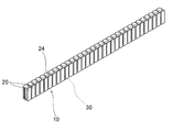
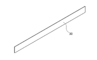
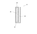
まず、枠部材40を変形させる際に用いられる枠部材変形用器具10の構成について図1乃至図3を用いて説明する。図1は、本実施の形態による枠部材変形用器具10を示す斜視図であり、図2は、図1に示す枠部材変形用器具10における接続部30を示す斜視図である。また、図3は、図1に示す枠部材変形用器具10における保持部20および接続部30の断面図である。 First, the configuration of the frame member deforming instrument 10 used when deforming the frame member 40 will be described with reference to FIGS. 1 to 3. FIG. 1 is a perspective view showing a frame member deforming instrument 10 according to the present embodiment, and FIG. 2 is a perspective view showing a connection portion 30 in the frame member deforming instrument 10 shown in FIG. Further, FIG. 3 is a cross-sectional view of the holding portion 20 and the connecting portion 30 in the frame member deforming instrument 10 shown in FIG.

図1乃至図3に示すように、本実施の形態による枠部材変形用器具10は、複数の保持部20と、可撓性を有する細長い接続部30とを備えている。図3に示すように、各保持部20には、接続部30が通る貫通穴22および溝部分24が形成されており、接続部30は各保持部20の貫通穴22を通っている。また、各保持部20の溝部分24に、後述する細長いプラスチック製の枠部材40を嵌め込むことができるようになっている。 As shown in FIGS. 1 to 3, the frame member deforming device 10 according to the present embodiment includes a plurality of holding portions 20 and a flexible elongated connecting portion 30. As shown in FIG. 3, each holding portion 20 is formed with a through hole 22 and a groove portion 24 through which the connecting portion 30 passes, and the connecting portion 30 passes through the through hole 22 of each holding portion 20. Further, an elongated plastic frame member 40, which will be described later, can be fitted into the groove portion 24 of each holding portion 20.

各保持部20は細長い略直方体形状のものとなっており、図1の奥行き方向(接続部30の長手方向)における各保持部20の長さは3mm〜10mmの範囲内の大きさとなっており、図1の高さ方向における各保持部20の高さは10mm〜20mmの範囲内の大きさとなっており、図3の左右方向における各保持部20の幅の大きさは3mm〜8mmの範囲内の大きさとなっている。各保持部20の材料は、例えば熱が加えられても変形しない樹脂や金属である。枠部材変形用器具10は、10個〜100個の範囲内の個数の保持部20を有しており、これらの保持部20の貫通穴22に接続部30が通されることにより各保持部20が互いに接続される。また、接続部30が貫通穴22を通る複数の保持部20のうち少なくとも両端に位置する保持部20が接続部30に取り付けられている。このことにより、接続部30が貫通穴22を通っている各保持部20が接続部30から離間してしまうことを防止することができる。一方、それ以外の各保持部20は接続部30に取り付けられていない。このため、接続部30が各保持部20の貫通穴22の内部で相対的に移動することができるようになるため、各保持部20は他の保持部20から独立して動くことが可能となる。このことにより、各保持部20の位置を、隣にある保持部20に対して、接続部30が貫通穴22内を移動する範囲内でずらすことができるようになっている。 Each holding portion 20 has an elongated substantially rectangular parallelepiped shape, and the length of each holding portion 20 in the depth direction (longitudinal direction of the connecting portion 30) of FIG. 1 is within the range of 3 mm to 10 mm. The height of each holding portion 20 in the height direction of FIG. 1 is in the range of 10 mm to 20 mm, and the width of each holding portion 20 in the left-right direction of FIG. 3 is in the range of 3 mm to 8 mm. It is the size of the inside. The material of each holding portion 20 is, for example, a resin or metal that does not deform even when heat is applied. The frame member deforming instrument 10 has a number of holding portions 20 in the range of 10 to 100, and each holding portion is formed by passing the connecting portion 30 through the through holes 22 of these holding portions 20. 20 are connected to each other. Further, holding portions 20 located at least at both ends of the plurality of holding portions 20 through which the connecting portion 30 passes through the through hole 22 are attached to the connecting portion 30. This makes it possible to prevent each holding portion 20 through which the connecting portion 30 passes through the through hole 22 from being separated from the connecting portion 30. On the other hand, each of the other holding portions 20 is not attached to the connecting portion 30. Therefore, since the connecting portion 30 can move relatively inside the through hole 22 of each holding portion 20, each holding portion 20 can move independently of the other holding portions 20. Become. As a result, the position of each holding portion 20 can be shifted with respect to the adjacent holding portion 20 within the range in which the connecting portion 30 moves in the through hole 22.

接続部30は、可撓性を有する細長い金属板から構成されている。具体的には、接続部30を構成する金属は、例えばアルミニウム、錫、アルミニウムを含む合金、錫を含む合金のうち少なくとも何れかのものを含む。アルミニウムを含む合金は、アルミニウムと錫との合金、アルミニウムと銅との合金、アルミニウムと銀との合金またはアルミニウムと銅と銀との合金等である。また、錫を含む合金は、錫と銅の合金、錫と銀の合金または錫と銅と銀の合金である。なお、接続部30を構成する金属はこのような材料に限定されることはない。可撓性を有する細長い金属板であれば、接続部30として他の種類の金属が用いられてもよい。また、接続部30は金属に限定されることはない。可撓性を有する細長い材料であれば、接続部30として金属板以外のものが用いられてもよい。このような接続部30の長手方向における長さは5cm〜30cmの範囲内の大きさとなっており、図2の高さ方向における接続部30の高さは5mm〜20mmの範囲内の大きさとなっており、接続部30の厚さは0.1mm〜5.0mmの範囲内の大きさとなっている。 The connecting portion 30 is made of a flexible elongated metal plate. Specifically, the metal constituting the connecting portion 30 includes, for example, at least one of aluminum, tin, an alloy containing aluminum, and an alloy containing tin. Alloys containing aluminum include alloys of aluminum and tin, alloys of aluminum and copper, alloys of aluminum and silver, alloys of aluminum, copper and silver, and the like. The alloy containing tin is an alloy of tin and copper, an alloy of tin and silver, or an alloy of tin and copper and silver. The metal constituting the connecting portion 30 is not limited to such a material. As long as it is a flexible elongated metal plate, another kind of metal may be used as the connecting portion 30. Further, the connecting portion 30 is not limited to metal. As long as it is a flexible and elongated material, a material other than a metal plate may be used as the connecting portion 30. The length of the connecting portion 30 in the longitudinal direction has a size in the range of 5 cm to 30 cm, and the height of the connecting portion 30 in the height direction of FIG. 2 has a size in the range of 5 mm to 20 mm. The thickness of the connecting portion 30 is in the range of 0.1 mm to 5.0 mm.

次に、このような枠部材変形用器具10を用いて枠部材40を変形させる動作について図4乃至図7を用いて説明する。 Next, the operation of deforming the frame member 40 by using the frame member deforming tool 10 will be described with reference to FIGS. 4 to 7.

まず、図4に示すように、枠部材変形用器具10における各保持部20の貫通穴22に細長い枠部材40を嵌め込む。ここで、枠部材40としては、弾力性を有し、熱可塑性樹脂または熱硬化性樹脂からなるプラスチックが用いられる。このようなプラスチックは、加熱される前は可撓性を有しているが熱が加えられると硬化し、その後に冷却しても硬化した状態が維持されるものである。熱可塑性樹脂として、例えばポリエチレン、ポリプロピレン、ポリ塩化ビニル、ポリスチレン、ポリ酢酸ビニル、ポリウレタン、テフロン、ABS樹脂、AS樹脂、アクリル樹脂等が挙げられる。また、熱硬化性樹脂として、例えばフェノール樹脂、エポキシ樹脂、メラミン樹脂、尿素樹脂(ユリア樹脂)、不飽和ポリエステル樹脂、アルキド樹脂、ポリウレタン、熱硬化性ポリイミド等が用いられる。このような枠部材40の長手方向における長さは5cm〜30cmの範囲内の大きさとなっており、図4の高さ方向における枠部材40の高さは5mm〜20mmの範囲内の大きさとなっており、枠部材40の厚さは0.1mm〜3.0mmの範囲内の大きさとなっている。 First, as shown in FIG. 4, an elongated frame member 40 is fitted into a through hole 22 of each holding portion 20 in the frame member deforming instrument 10. Here, as the frame member 40, a plastic having elasticity and made of a thermoplastic resin or a thermosetting resin is used. Such plastics are flexible before being heated, but are cured when heat is applied, and are maintained in a cured state even when cooled thereafter. Examples of the thermoplastic resin include polyethylene, polypropylene, polyvinyl chloride, polystyrene, polyvinyl acetate, polyurethane, Teflon, ABS resin, AS resin, acrylic resin and the like. Further, as the thermosetting resin, for example, phenol resin, epoxy resin, melamine resin, urea resin (urea resin), unsaturated polyester resin, alkyd resin, polyurethane, thermosetting polyimide and the like are used. The length of the frame member 40 in the longitudinal direction has a size in the range of 5 cm to 30 cm, and the height of the frame member 40 in the height direction of FIG. 4 has a size in the range of 5 mm to 20 mm. The thickness of the frame member 40 is in the range of 0.1 mm to 3.0 mm.

次に、図5に示すように、枠部材40が各保持部20の溝部分24に嵌め込まれた枠部材変形用器具10をマスク着用予定者の顔に当てて変形させることによりフィッティングを行う。具体的には、枠部材変形用器具10の中央箇所がマスク着用予定者の鼻筋に当たるようにする。このことにより、枠部材変形用器具10および枠部材40がマスク着用予定者の顔の形状に沿って変形する。この際に、枠部材変形用器具10の各保持部20が隣にある保持部20に対して移動可能となっていることにより、より精度良く各保持部20をマスク着用予定者の顔にフィッティングさせることができる。 Next, as shown in FIG. 5, fitting is performed by deforming the frame member 40 by applying the frame member deforming device 10 fitted in the groove portion 24 of each holding portion 20 to the face of a person who is planning to wear a mask. Specifically, the central portion of the frame member deforming device 10 is made to hit the nose muscle of the person who is going to wear the mask. As a result, the frame member deforming device 10 and the frame member 40 are deformed along the shape of the face of the person who is going to wear the mask. At this time, since each holding portion 20 of the frame member deforming device 10 is movable with respect to the adjacent holding portion 20, each holding portion 20 is more accurately fitted to the face of the person who is going to wear the mask. Can be made to.

枠部材変形用器具10をマスク着用予定者の顔に当てて変形させることによりフィッティングを行った後、マスク着用予定者の顔から枠部材変形用器具10を離す。この際に、接続部30の材料が可撓性を有する金属であるため、マスク着用予定者の顔から枠部材変形用器具10を離しても変形した接続部30の形状が維持される。よって、変形した枠部材40の形状も維持される。そして、枠部材40が各保持部20の溝部分24に嵌め込まれた状態で枠部材変形用器具10および枠部材40を加熱する。具体的には、変形した枠部材変形用器具10および枠部材40を例えば40℃以上100℃以下の熱湯に入れることにより加熱する。あるいは、変形した枠部材変形用器具10および枠部材40にドライヤー等で熱風を供給することにより枠部材変形用器具10および枠部材40を加熱してもよい。このことにより、各保持部20の溝部分24に嵌め込まれている枠部材40が硬化する。 After fitting by applying the frame member deforming device 10 to the face of the person who is going to wear the mask and deforming it, the frame member deforming device 10 is separated from the face of the person who is going to wear the mask. At this time, since the material of the connecting portion 30 is a flexible metal, the deformed shape of the connecting portion 30 is maintained even if the frame member deforming device 10 is separated from the face of the person who is going to wear the mask. Therefore, the deformed shape of the frame member 40 is also maintained. Then, the frame member deforming instrument 10 and the frame member 40 are heated in a state where the frame member 40 is fitted into the groove portion 24 of each holding portion 20. Specifically, the deformed frame member deforming instrument 10 and the frame member 40 are heated by, for example, putting them in boiling water of 40 ° C. or higher and 100 ° C. or lower. Alternatively, the frame member deforming instrument 10 and the frame member 40 may be heated by supplying hot air to the deformed frame member deforming instrument 10 and the frame member 40 with a dryer or the like. As a result, the frame member 40 fitted in the groove portion 24 of each holding portion 20 is cured.

その後、図6に示すように、加熱された枠部材変形用器具10および枠部材40を冷却し、当該枠部材変形用器具10から枠部材40を取り出す。このことにより、図7に示すような、マスク着用予定者の顔の形状に沿って変形した枠部材40が得られる。図7に示すように、変形した枠部材40は、中央にある山形状部分42と、山形状部分42の両側にある谷形状部分44とを含んでいる。山形状部分42は、マスク着用予定者の鼻の形状に沿って変形したものであり、谷形状部分44は、マスク着用予定者の鼻と頬の間の谷部分の形状に沿って変形したものである。 After that, as shown in FIG. 6, the heated frame member deforming instrument 10 and the frame member 40 are cooled, and the frame member 40 is taken out from the frame member deforming instrument 10. As a result, as shown in FIG. 7, the frame member 40 deformed along the shape of the face of the person who is going to wear the mask can be obtained. As shown in FIG. 7, the deformed frame member 40 includes a mountain-shaped portion 42 in the center and valley-shaped portions 44 on both sides of the mountain-shaped portion 42. The mountain-shaped portion 42 is deformed along the shape of the nose of the person planning to wear the mask, and the valley-shaped portion 44 is deformed along the shape of the valley portion between the nose and cheeks of the person planning to wear the mask. Is.

次に、マスク本体50に形成されているポケット54に枠部材40を入れる。ここで、本実施の形態によるマスクは、マスク本体50と、マスク本体50の両側縁に設けられた耳に引っ掛けるための左右一対のバンド52と、マスク本体50の表面または裏面に形成されたポケット54とを有しており、ポケット54に枠部材40を収容することができるようになっている。また、ポケット54は、マスクにおけるマスク着用予定者の鼻が当たる部分の近傍に形成されている。このようにして、ポケット54に枠部材40を入れると、図9に示すような、マスク着用予定者の顔の形状に沿った枠部材40が設けられたマスクが得られる。 Next, the frame member 40 is put into the pocket 54 formed in the mask body 50. Here, the mask according to the present embodiment includes a mask main body 50, a pair of left and right bands 52 provided on both side edges of the mask main body 50 for hooking on ears, and pockets formed on the front surface or the back surface of the mask main body 50. It has 54, and the frame member 40 can be accommodated in the pocket 54. Further, the pocket 54 is formed in the vicinity of the portion of the mask where the nose of the person who intends to wear the mask touches. When the frame member 40 is inserted into the pocket 54 in this way, a mask provided with the frame member 40 that conforms to the shape of the face of the person who will wear the mask, as shown in FIG. 9, can be obtained.

図10は、本実施の形態によるマスクをマスク着用予定者が着用したときの状態を示す図である。なお、図10においてマスク着用予定者の顔を見やすくするためにマスクを二点鎖線で示している。人の顔のうち図10において参照符号Aで示す鼻筋の近傍の箇所は、この人が会話しても大きくは動かない部分である。一方、人の顔のうち図10において参照符号Bで示す頬の近傍の箇所は、この人が会話したときに動く部分である。そして、人の顔のうち参照符号Bで示す箇所が動くと、図10において参照符号Cで示す箇所において、従来のマスクでは人の顔との間に隙間が生じてしまう。これに対し、本実施の形態によるマスクでは、人の顔のうち図10において参照符号Aで示す鼻筋の近傍の箇所に枠部材40の山形状部分42が位置し、図10において参照符号Cで示す鼻と頬の間の谷間の箇所に枠部材40の谷形状部分44が位置するようになる。また、枠部材40は弾力性を有する部材から構成されている。このため、本実施の形態によるマスクをマスク着用予定者が着用したときに、人の顔における図10において参照符号Cで示す鼻と頬の間の谷間の箇所に枠部材40の谷形状部分44が嵌まり込むため人の顔とマスクとの間に隙間が生じることを防止することができる。また、人の顔のうち参照符号Bで示す箇所が動いても、枠部材40が弾力性を有する材料から構成されているため、人の顔の動きに合わせて枠部材40の谷形状部分44が変形することにより、図10において参照符号Cで示す箇所で人の顔とマスクとの間に隙間が生じることはない。 FIG. 10 is a diagram showing a state when a person planning to wear a mask wears the mask according to the present embodiment. In FIG. 10, the mask is shown by a chain double-dashed line to make it easier to see the face of the person who will wear the mask. The portion of the human face in the vicinity of the nose muscle indicated by the reference numeral A in FIG. 10 is a portion that does not move significantly even when the person speaks. On the other hand, a portion of a person's face near the cheek indicated by reference numeral B in FIG. 10 is a portion that moves when the person talks. Then, when the portion of the human face indicated by the reference reference numeral B moves, a gap is formed between the portion indicated by the reference numeral C in FIG. 10 and the human face in the conventional mask. On the other hand, in the mask according to the present embodiment, the mountain-shaped portion 42 of the frame member 40 is located in the vicinity of the nose muscle indicated by the reference reference numeral A in FIG. 10 on the human face, and the reference reference numeral C is used in FIG. The valley-shaped portion 44 of the frame member 40 is located in the valley between the nose and the cheek shown. Further, the frame member 40 is made of an elastic member. Therefore, when the mask according to the present embodiment is worn by a person who intends to wear the mask, the valley-shaped portion 44 of the frame member 40 is located in the valley between the nose and the cheek indicated by the reference numeral C in FIG. 10 on the human face. It is possible to prevent a gap from being formed between the human face and the mask because the mask is fitted. Further, since the frame member 40 is made of an elastic material even if the portion of the human face indicated by the reference numeral B moves, the valley-shaped portion 44 of the frame member 40 is made according to the movement of the human face. Does not cause a gap between the human face and the mask at the location indicated by the reference numeral C in FIG.

以上のような構成からなる本実施の形態のマスク製造方法によれば、細長いプラスチック製の枠部材40を枠部材変形用器具10に収容する工程と、枠部材40が収容された枠部材変形用器具10をマスク着用予定者の顔に当てて変形させることによりフィッティングを行う工程と、変形した枠部材変形用器具10および枠部材40を加熱することにより枠部材40を硬化させる工程と、加熱された枠部材変形用器具10および枠部材40を冷却し、当該枠部材変形用器具10から枠部材40を取り出す工程と、マスク本体50に形成されているポケット54に枠部材40を入れる工程とを備えている。このようなマスク製造方法によれば、枠部材変形用器具10および枠部材40を加熱する前にマスク着用予定者の顔に当てて変形させることによりフィッティングを行うため、安全かつ簡単な方法でオーダーメイドのマスクを製造することができる。また、ユーザの顔の形状に合わせて枠部材40を変形させるため、人の顔との間に隙間が生じることを防止することができるマスクをオーダーメイドで製造することができる。 According to the mask manufacturing method of the present embodiment having the above-described configuration, a step of accommodating the elongated plastic frame member 40 in the frame member deforming tool 10 and a frame member deforming method in which the frame member 40 is accommodated are used. A step of fitting by applying the instrument 10 to the face of a person who is going to wear a mask and deforming it, a step of curing the deformed frame member deforming instrument 10 and the frame member 40 by heating the frame member 40, and heating. A step of cooling the frame member deforming tool 10 and the frame member 40 and taking out the frame member 40 from the frame member deforming tool 10 and a step of inserting the frame member 40 into the pocket 54 formed in the mask main body 50. I have. According to such a mask manufacturing method, fitting is performed by applying the frame member deforming device 10 and the frame member 40 to the face of the person who is going to wear the mask and deforming them before heating, so that the order can be made by a safe and easy method. Made-to-order masks can be manufactured. Further, since the frame member 40 is deformed according to the shape of the user's face, it is possible to manufacture a custom-made mask that can prevent a gap from being formed between the frame member 40 and the human face.

また、本実施の形態のマスク製造方法においては、枠部材変形用器具10は、可撓性を有する金属としての接続部30を含んでいる。このことにより、枠部材40が収容された枠部材変形用器具10をマスク着用予定者の顔に当てて変形させることによりフィッティングを行った後、マスク着用予定者の顔から枠部材変形用器具10を離しても、変形した枠部材変形用器具10および枠部材40の形状を維持することができる。 Further, in the mask manufacturing method of the present embodiment, the frame member deforming instrument 10 includes a connecting portion 30 as a flexible metal. As a result, after fitting by applying the frame member deforming device 10 containing the frame member 40 to the face of the person planning to wear the mask and deforming it, the frame member deforming device 10 is deformed from the face of the person planning to wear the mask. The shapes of the deformed frame member deforming device 10 and the frame member 40 can be maintained even when the two are separated.

また、本実施の形態のマスク製造方法においては、枠部材40を硬化させる工程において、変形した枠部材変形用器具10および枠部材40を40℃以上100℃以下の熱湯に入れることにより加熱するようになっている。あるいは、枠部材40を硬化させる工程において、変形した枠部材変形用器具10および枠部材40に熱風を供給することにより加熱するようになっている。この場合には、簡単な方法で枠部材40を加熱することができる。 Further, in the mask manufacturing method of the present embodiment, in the step of curing the frame member 40, the deformed frame member deforming instrument 10 and the frame member 40 are heated by putting them in boiling water of 40 ° C. or higher and 100 ° C. or lower. It has become. Alternatively, in the step of curing the frame member 40, the deformed frame member deforming instrument 10 and the frame member 40 are heated by supplying hot air. In this case, the frame member 40 can be heated by a simple method.

また、本実施の形態のマスク製造方法においては、ポケット54は、マスクにおけるマスク着用予定者の鼻が当たる部分の近傍に形成されている。この場合には、製造されたマスクにより、枠部材40によってユーザの顔における鼻の近傍の箇所とマスクとの間に隙間が生じることを防止することができる。 Further, in the mask manufacturing method of the present embodiment, the pocket 54 is formed in the vicinity of the portion of the mask where the nose of the person who intends to wear the mask touches. In this case, the manufactured mask can prevent the frame member 40 from creating a gap between the mask and a portion of the user's face near the nose.

また、本実施の形態の枠部材変形用器具10によれば、複数の保持部20と、可撓性を有する細長い接続部30とを備え、保持部20には、接続部30が通る貫通穴22および細長い枠部材40を収容するための収容部分(具体的には、溝部分24)が形成されており、接続部30は各保持部20の貫通穴22を通っており、枠部材40を各保持部20の収容部分にまたがって収容することができるようになっている。この場合には、本実施の形態の枠部材変形用器具10を用いて枠部材40を変形させることができるため、安全かつ簡単な方法でオーダーメイドのマスクを製造することができる。また、ユーザの顔の形状に合わせて枠部材40を変形させることができるため、人の顔との間に隙間が生じることを防止することができるマスクを得ることができる。 Further, according to the frame member deforming device 10 of the present embodiment, a plurality of holding portions 20 and a flexible elongated connecting portion 30 are provided, and the holding portion 20 has a through hole through which the connecting portion 30 passes. A housing portion (specifically, a groove portion 24) for accommodating the 22 and the elongated frame member 40 is formed, and the connecting portion 30 passes through the through hole 22 of each holding portion 20 to accommodate the frame member 40. It can be accommodated across the accommodating portions of each holding portion 20. In this case, since the frame member 40 can be deformed by using the frame member deforming tool 10 of the present embodiment, a custom-made mask can be manufactured by a safe and simple method. Further, since the frame member 40 can be deformed according to the shape of the user's face, it is possible to obtain a mask capable of preventing a gap from being formed between the frame member 40 and the human face.

また、本実施の形態の枠部材変形用器具10においては、接続部30が貫通穴22を通る複数の保持部20のうち少なくとも両端に位置する保持部20が接続部30に取り付けられている。この場合は、接続部30が貫通穴22を通っている各保持部20が接続部30から離間してしまうことを防止することができる。また、接続部30が貫通穴22を通る複数の保持部20のうち両端に位置する保持部20以外の各保持部20は接続部30に取り付けられておらず、接続部30が各保持部20の貫通穴22の内部で相対的に移動することができるようになっている。このことにより、各保持部20は他の保持部20から独立して動くことが可能となり、よって、各保持部20の位置を、隣にある保持部20に対して、接続部30が貫通穴22内を移動する範囲内でずらすことができるようになっている。 Further, in the frame member deforming device 10 of the present embodiment, holding portions 20 located at least at both ends of the plurality of holding portions 20 through which the connecting portion 30 passes through the through hole 22 are attached to the connecting portion 30. In this case, it is possible to prevent each holding portion 20 through which the connecting portion 30 passes through the through hole 22 from being separated from the connecting portion 30. Further, among the plurality of holding portions 20 through which the connecting portion 30 passes through the through hole 22, each holding portion 20 other than the holding portions 20 located at both ends is not attached to the connecting portion 30, and the connecting portion 30 is attached to each holding portion 20. It is possible to move relatively inside the through hole 22 of the. As a result, each holding portion 20 can move independently of the other holding portions 20, so that the connecting portion 30 makes a through hole for the position of each holding portion 20 with respect to the adjacent holding portion 20. It is possible to shift within the range of movement within 22.

また、本実施の形態の枠部材変形用器具10においては、接続部30の材料は金属である。また、金属はアルミニウム、錫、アルミニウムを含む合金、錫を含む合金のうち少なくとも何れかのものを含む。この場合は、枠部材40が嵌め込まれた枠部材変形用器具10をマスク着用予定者の顔に当てて変形させることによりフィッティングを行う際に、常温でも接続部30を変形させることができる。 Further, in the frame member deforming device 10 of the present embodiment, the material of the connecting portion 30 is metal. Further, the metal includes at least one of aluminum, tin, an alloy containing aluminum, and an alloy containing tin. In this case, the connection portion 30 can be deformed even at room temperature when fitting is performed by applying the frame member deforming device 10 into which the frame member 40 is fitted to the face of a person who is planning to wear a mask and deforming the face.

また、本実施の形態のマスクによれば、ポケット54が形成されているマスク本体50と、ポケット54に入れられている細長いプラスチック製の枠部材40と、を備え、ポケット54は、マスクにおけるマスク着用予定者の鼻が当たる部分の近傍に形成されており、枠部材40は、変形した状態で加熱されることにより硬化した後に冷却されたものである。この場合は、ユーザの顔の形状に合わせて枠部材40を変形させることができるため、人の顔との間に隙間が生じることを防止することができるオーダーメイドのマスクを得ることができる。 Further, according to the mask of the present embodiment, the mask main body 50 in which the pocket 54 is formed and the elongated plastic frame member 40 housed in the pocket 54 are provided, and the pocket 54 is a mask in the mask. The frame member 40 is formed in the vicinity of the portion where the nose of the person to be worn touches, and the frame member 40 is cooled by being heated by being heated in a deformed state. In this case, since the frame member 40 can be deformed according to the shape of the user's face, it is possible to obtain a custom-made mask that can prevent a gap from being formed between the frame member 40 and the human face.

また、本実施の形態のマスクにおいては、枠部材40は、中央にある山形状部分42と、山形状部分42の両側にある谷形状部分44とを含んでいる。この場合は、人の顔のうち頬の近傍の箇所が動いても、枠部材40が弾力性を有する部材から構成されているため、人の顔の動きに合わせて枠部材40の谷形状部分44が変形することにより、鼻と頬の間の窪みで人の顔とマスクとの間に隙間が生じることはない。 Further, in the mask of the present embodiment, the frame member 40 includes a mountain-shaped portion 42 in the center and valley-shaped portions 44 on both sides of the mountain-shaped portion 42. In this case, since the frame member 40 is composed of elastic members even if the portion of the human face near the cheeks moves, the valley-shaped portion of the frame member 40 is formed according to the movement of the human face. Due to the deformation of 44, there is no gap between the human face and the mask in the depression between the nose and cheeks.

なお、本実施の形態によるマスク製造方法、枠部材変形用器具およびマスクは、上述したような態様に限定されることはなく、様々な変更を加えることができる。 The mask manufacturing method, the frame member deforming tool, and the mask according to the present embodiment are not limited to the above-described aspects, and various changes can be made.

例えば、本実施の形態によるマスク製造方法で用いられる枠部材変形用器具は、図1乃至図3に示す枠部材変形用器具10に限定されることはない。細長いプラスチック製の枠部材40を嵌め込むことができるものであれば、枠部材変形用器具として、図1乃至図3に示す枠部材変形用器具10以外の構成のものが用いられもよい。 For example, the frame member deforming device used in the mask manufacturing method according to the present embodiment is not limited to the frame member deforming device 10 shown in FIGS. 1 to 3. As long as an elongated plastic frame member 40 can be fitted, a frame member deforming tool other than the frame member deforming tool 10 shown in FIGS. 1 to 3 may be used.

具体的には、例えば、複数の保持部20において、枠部材40が嵌め込まれる溝部分24が形成されている代わりに、枠部材40が通過する貫通穴が形成されていてもよい。また、別の態様として、各保持部20の貫通穴22に接続部30および枠部材40の両方が入るようになっていてもよい。すなわち、各保持部20において、接続部30が通る貫通穴22および枠部材40を収容する収容部分が共通のものとなっていてもよい。 Specifically, for example, in the plurality of holding portions 20, instead of forming the groove portion 24 into which the frame member 40 is fitted, a through hole through which the frame member 40 passes may be formed. Further, as another aspect, both the connecting portion 30 and the frame member 40 may be inserted into the through holes 22 of each holding portion 20. That is, in each holding portion 20, the through hole 22 through which the connecting portion 30 passes and the accommodating portion accommodating the frame member 40 may be common.

また、本実施の形態によるマスク製造方法で用いられる枠部材変形用器具として、複数の保持部20ではなく、断面がU字形状となっており可撓性を有する細長い金属体が用いられてもよい。金属体は、例えば錫、錫と銅の合金、錫と銀の合金または錫と銅と銀の合金から構成される。この場合は、金属体のU字形状の間に枠部材40を挟み込み、枠部材40が挟み込まれた金属体をマスク着用予定者の顔に当てて変形させることによりフィッティングを行う。そして、変形した金属体および枠部材40を加熱し、加熱された金属体および枠部材40を冷却した後、金属体から枠部材40を取り出す。その後、マスク本体50に形成されているポケット54に枠部材40を入れる。このようなマスク製造方法でも、金属体および枠部材40を加熱する前にマスク着用予定者の顔に当てて変形させることによりフィッティングを行うため、安全かつ簡単な方法でオーダーメイドのマスクを製造することができる。また、ユーザの顔の形状に合わせて枠部材40を変形させるため、人の顔との間に隙間が生じることを防止することができるマスクを得ることができる。 Further, as the frame member deforming device used in the mask manufacturing method according to the present embodiment, even if an elongated metal body having a U-shaped cross section and flexibility is used instead of the plurality of holding portions 20. good. The metal body is composed of, for example, tin, an alloy of tin and copper, an alloy of tin and silver, or an alloy of tin and copper and silver. In this case, the frame member 40 is sandwiched between the U-shapes of the metal body, and the metal body in which the frame member 40 is sandwiched is applied to the face of the person who is going to wear the mask and deformed to perform fitting. Then, the deformed metal body and the frame member 40 are heated, the heated metal body and the frame member 40 are cooled, and then the frame member 40 is taken out from the metal body. After that, the frame member 40 is put into the pocket 54 formed in the mask body 50. Even in such a mask manufacturing method, since fitting is performed by applying the metal body and the frame member 40 to the face of the person who will wear the mask and deforming it before heating, a custom-made mask is manufactured by a safe and easy method. be able to. Further, since the frame member 40 is deformed according to the shape of the user's face, it is possible to obtain a mask capable of preventing a gap from being formed between the frame member 40 and the human face.

また、枠部材40は細長い板状のものに限定されることはない。枠部材40として、細長い棒状のもの等、板状以外の形状のものが用いられてもよい。 Further, the frame member 40 is not limited to an elongated plate shape. As the frame member 40, a member having a shape other than a plate shape such as an elongated rod shape may be used.

10 枠部材変形用器具
20 保持部
22 貫通穴
24 溝部分
30 接続部
40 枠部材
42 山形状部分
44 谷形状部分
50 マスク本体
52 バンド
54 ポケット
10 Frame member deformation device 20 Holding part 22 Through hole 24 Groove part 30 Connection part 40 Frame member 42 Mountain-shaped part 44 Valley-shaped part 50 Mask body 52 Band 54 Pocket

Claims (10)

細長いプラスチック製の枠部材を枠部材変形用器具に収容する工程と、
前記枠部材が収容された前記枠部材変形用器具をマスク着用予定者の顔に当てて変形させることによりフィッティングを行う工程と、
変形した前記枠部材変形用器具および前記枠部材を加熱することにより前記枠部材を硬化させる工程と、
加熱された前記枠部材変形用器具および前記枠部材を冷却し、当該枠部材変形用器具から前記枠部材を取り出す工程と、
マスク本体に形成されているポケットに前記枠部材を入れる工程と、
を備えた、マスク製造方法。
The process of accommodating an elongated plastic frame member in a frame member deformation device,
A step of performing fitting by applying the frame member deforming device containing the frame member to the face of a person who is planning to wear a mask and deforming the mask member.
A step of hardening the frame member by heating the deformed frame member deforming tool and the frame member, and
A step of cooling the heated frame member deforming device and the frame member, and taking out the frame member from the frame member deforming device.
The process of inserting the frame member into the pocket formed in the mask body,
A mask manufacturing method.
前記枠部材変形用器具は、可撓性を有する金属を含む、請求項1記載のマスク製造方法。 The mask manufacturing method according to claim 1, wherein the frame member deforming device contains a flexible metal. 前記枠部材を硬化させる工程において、変形した前記枠部材変形用器具および前記枠部材を40℃以上100℃以下の湯に入れることにより加熱する、請求項1または2記載のマスク製造方法。 The mask manufacturing method according to claim 1 or 2, wherein in the step of curing the frame member, the deformed frame member deforming device and the frame member are heated by putting them in hot water of 40 ° C. or higher and 100 ° C. or lower. 前記枠部材を硬化させる工程において、変形した前記枠部材変形用器具および前記枠部材に熱風を供給することにより加熱する、請求項1または2記載のマスク製造方法。 The mask manufacturing method according to claim 1 or 2, wherein in the step of curing the frame member, the deformed frame member deforming device and the frame member are heated by supplying hot air. 前記ポケットは、前記マスク本体におけるマスク着用予定者の鼻が当たる部分の近傍に形成されている、請求項1乃至4のいずれか一項に記載のマスク製造方法。 The mask manufacturing method according to any one of claims 1 to 4, wherein the pocket is formed in the vicinity of a portion of the mask body where the nose of a person who intends to wear the mask touches. 複数の保持部と、
可撓性を有する細長い接続部と、
を備え、
前記保持部には、前記接続部が通る貫通穴および細長い枠部材を収容するための収容部分が形成されており、
前記接続部は各前記保持部の前記貫通穴を通っており、
前記枠部材を各前記保持部の前記収容部分にまたがって収容することができるようになっている、枠部材変形用器具。
With multiple holders
Flexible elongated connections and
With
The holding portion is formed with a through hole through which the connecting portion passes and an accommodating portion for accommodating an elongated frame member.
The connecting portion passes through the through hole of each of the holding portions.
A frame member deforming device capable of accommodating the frame member across the accommodating portion of each of the holding portions.
前記接続部が前記貫通穴を通る複数の前記保持部のうち少なくとも両端に位置する前記保持部が前記接続部に取り付けられている、請求項6記載の枠部材変形用器具。 The frame member deforming device according to claim 6, wherein the holding portions located at least at both ends of the plurality of holding portions through which the connecting portion passes through the through hole are attached to the connecting portion. 前記接続部が前記貫通穴を通る複数の前記保持部のうち両端に位置する前記保持部以外の各前記保持部は前記接続部に取り付けられておらず、前記接続部が各前記保持部の前記貫通穴の内部で相対的に移動することができるようになっている、請求項7記載の枠部材変形用器具。 Each of the holding portions other than the holding portions located at both ends of the plurality of holding portions through which the connecting portion passes through the through hole is not attached to the connecting portion, and the connecting portion is the said portion of each of the holding portions. The frame member deforming device according to claim 7, which is capable of relatively moving inside the through hole. 前記接続部の材料は金属である、請求項6乃至8のいずれか一項に記載の枠部材変形用器具。 The frame member deforming device according to any one of claims 6 to 8, wherein the material of the connecting portion is metal. 前記金属はアルミニウム、錫、アルミニウムを含む合金、錫を含む合金のうち少なくとも何れかのものを含む、請求項9記載の枠部材変形用器具。 The frame member deforming device according to claim 9, wherein the metal includes at least one of aluminum, tin, an alloy containing aluminum, and an alloy containing tin.
JP2021092796A 2021-06-02 2021-06-02 Mask manufacturing method and frame member deformation equipment Active JP6960552B1 (en)

Priority Applications (1)

Application Number Priority Date Filing Date Title
JP2021092796A JP6960552B1 (en) 2021-06-02 2021-06-02 Mask manufacturing method and frame member deformation equipment

Applications Claiming Priority (1)

Application Number Priority Date Filing Date Title
JP2021092796A JP6960552B1 (en) 2021-06-02 2021-06-02 Mask manufacturing method and frame member deformation equipment

Publications (2)

Publication Number Publication Date
JP6960552B1 true JP6960552B1 (en) 2021-11-05
JP2022185256A JP2022185256A (en) 2022-12-14

Family

ID=78409684

Family Applications (1)

Application Number Title Priority Date Filing Date
JP2021092796A Active JP6960552B1 (en) 2021-06-02 2021-06-02 Mask manufacturing method and frame member deformation equipment

Country Status (1)

Country Link
JP (1) JP6960552B1 (en)

Citations (4)

* Cited by examiner, † Cited by third party
Publication number Priority date Publication date Assignee Title
JPS60215372A (en) * 1984-03-27 1985-10-28 ミネソタ マイニング アンド マニユフアクチユアリング コンパニ− Molded fibrous filter product and its production
JP2008259737A (en) * 2007-04-13 2008-10-30 Yoshio Jinbo Mask manufacturing method, mask and mask manufacturing set
JP2009505734A (en) * 2005-08-25 2009-02-12 スリーエム イノベイティブ プロパティズ カンパニー Respirator with preloaded nose clip
JP2013188281A (en) * 2012-03-13 2013-09-26 Mitsuaki Kamiyama Mask-auxiliary member, mask and insertion member

Patent Citations (4)

* Cited by examiner, † Cited by third party
Publication number Priority date Publication date Assignee Title
JPS60215372A (en) * 1984-03-27 1985-10-28 ミネソタ マイニング アンド マニユフアクチユアリング コンパニ− Molded fibrous filter product and its production
JP2009505734A (en) * 2005-08-25 2009-02-12 スリーエム イノベイティブ プロパティズ カンパニー Respirator with preloaded nose clip
JP2008259737A (en) * 2007-04-13 2008-10-30 Yoshio Jinbo Mask manufacturing method, mask and mask manufacturing set
JP2013188281A (en) * 2012-03-13 2013-09-26 Mitsuaki Kamiyama Mask-auxiliary member, mask and insertion member

Also Published As

Publication number Publication date
JP2022185256A (en) 2022-12-14

Similar Documents

Publication Publication Date Title
JP6618456B2 (en) Hairdressing equipment
EP2521521B1 (en) Face fit adjustment system
US2283752A (en) Eye shield
JP6118475B1 (en) Blade set, hair cutting device, and related manufacturing method
US20160361511A9 (en) Customized medical devices and apparel
US5697386A (en) Hair band
JP6780157B2 (en) Eyelash curler and heated eyelash curler system
EP0898948A1 (en) Sport goggle structure
KR20190122516A (en) Functional Facial Sealed Contact Mask and Manufacturing Method Thereof
JP2022079475A (en) Headgear for first responders
US6644806B2 (en) Resilient non-smooth projection member on eyeglass temples and nose pads
KR20010012437A (en) Razor assembly
JP6960552B1 (en) Mask manufacturing method and frame member deformation equipment
US7513618B2 (en) Nose pad
EP0346480B1 (en) Wig having shape retaining member
US20140185002A1 (en) Eyewear and eyewear frames with contoured temples
JP6932139B2 (en) Temple bar and method of manufacturing temple bar
JPS58162927A (en) Elastically compressing foam seal able to be fitted tightly on irregular surface
US3194004A (en) Wrist watch protector
JP2016503907A (en) Temple support for glasses
US2390523A (en) Nose guard for eyeglasses
JP2022052599A (en) Mask clip
JP2549553B2 (en) Wig with mold holding member
JP2022048681A (en) Face covering tool
TWI747675B (en) A mask structure

Legal Events

Date Code Title Description
A621 Written request for application examination

Free format text: JAPANESE INTERMEDIATE CODE: A621

Effective date: 20210602

A871 Explanation of circumstances concerning accelerated examination

Free format text: JAPANESE INTERMEDIATE CODE: A871

Effective date: 20210602

A131 Notification of reasons for refusal

Free format text: JAPANESE INTERMEDIATE CODE: A131

Effective date: 20210903

A521 Request for written amendment filed

Free format text: JAPANESE INTERMEDIATE CODE: A523

Effective date: 20210909

TRDD Decision of grant or rejection written
A01 Written decision to grant a patent or to grant a registration (utility model)

Free format text: JAPANESE INTERMEDIATE CODE: A01

Effective date: 20211008

A61 First payment of annual fees (during grant procedure)

Free format text: JAPANESE INTERMEDIATE CODE: A61

Effective date: 20211011

R150 Certificate of patent or registration of utility model

Ref document number: 6960552

Country of ref document: JP

Free format text: JAPANESE INTERMEDIATE CODE: R150