JP6958314B2 - Whole building air conditioning system - Google Patents
Whole building air conditioning system Download PDFInfo
- Publication number
- JP6958314B2 JP6958314B2 JP2017238619A JP2017238619A JP6958314B2 JP 6958314 B2 JP6958314 B2 JP 6958314B2 JP 2017238619 A JP2017238619 A JP 2017238619A JP 2017238619 A JP2017238619 A JP 2017238619A JP 6958314 B2 JP6958314 B2 JP 6958314B2
- Authority
- JP
- Japan
- Prior art keywords
- temperature
- air
- prediction
- unit
- conditioning
- Prior art date
- Legal status (The legal status is an assumption and is not a legal conclusion. Google has not performed a legal analysis and makes no representation as to the accuracy of the status listed.)
- Active
Links
Images


Classifications
-
- F—MECHANICAL ENGINEERING; LIGHTING; HEATING; WEAPONS; BLASTING
- F24—HEATING; RANGES; VENTILATING
- F24F—AIR-CONDITIONING; AIR-HUMIDIFICATION; VENTILATION; USE OF AIR CURRENTS FOR SCREENING
- F24F11/00—Control or safety arrangements
- F24F11/70—Control systems characterised by their outputs; Constructional details thereof
- F24F11/72—Control systems characterised by their outputs; Constructional details thereof for controlling the supply of treated air, e.g. its pressure
- F24F11/74—Control systems characterised by their outputs; Constructional details thereof for controlling the supply of treated air, e.g. its pressure for controlling air flow rate or air velocity
- F24F11/76—Control systems characterised by their outputs; Constructional details thereof for controlling the supply of treated air, e.g. its pressure for controlling air flow rate or air velocity by means responsive to temperature, e.g. bimetal springs
-
- F—MECHANICAL ENGINEERING; LIGHTING; HEATING; WEAPONS; BLASTING
- F24—HEATING; RANGES; VENTILATING
- F24F—AIR-CONDITIONING; AIR-HUMIDIFICATION; VENTILATION; USE OF AIR CURRENTS FOR SCREENING
- F24F11/00—Control or safety arrangements
- F24F11/62—Control or safety arrangements characterised by the type of control or by internal processing, e.g. using fuzzy logic, adaptive control or estimation of values
- F24F11/63—Electronic processing
-
- F—MECHANICAL ENGINEERING; LIGHTING; HEATING; WEAPONS; BLASTING
- F24—HEATING; RANGES; VENTILATING
- F24F—AIR-CONDITIONING; AIR-HUMIDIFICATION; VENTILATION; USE OF AIR CURRENTS FOR SCREENING
- F24F3/00—Air-conditioning systems in which conditioned primary air is supplied from one or more central stations to distributing units in the rooms or spaces where it may receive secondary treatment; Apparatus specially designed for such systems
- F24F3/044—Systems in which all treatment is given in the central station, i.e. all-air systems
-
- G—PHYSICS
- G05—CONTROLLING; REGULATING
- G05B—CONTROL OR REGULATING SYSTEMS IN GENERAL; FUNCTIONAL ELEMENTS OF SUCH SYSTEMS; MONITORING OR TESTING ARRANGEMENTS FOR SUCH SYSTEMS OR ELEMENTS
- G05B19/00—Programme-control systems
- G05B19/02—Programme-control systems electric
- G05B19/04—Programme control other than numerical control, i.e. in sequence controllers or logic controllers
- G05B19/042—Programme control other than numerical control, i.e. in sequence controllers or logic controllers using digital processors
-
- F—MECHANICAL ENGINEERING; LIGHTING; HEATING; WEAPONS; BLASTING
- F24—HEATING; RANGES; VENTILATING
- F24F—AIR-CONDITIONING; AIR-HUMIDIFICATION; VENTILATION; USE OF AIR CURRENTS FOR SCREENING
- F24F2110/00—Control inputs relating to air properties
- F24F2110/10—Temperature
-
- G—PHYSICS
- G05—CONTROLLING; REGULATING
- G05B—CONTROL OR REGULATING SYSTEMS IN GENERAL; FUNCTIONAL ELEMENTS OF SUCH SYSTEMS; MONITORING OR TESTING ARRANGEMENTS FOR SUCH SYSTEMS OR ELEMENTS
- G05B2219/00—Program-control systems
- G05B2219/20—Pc systems
- G05B2219/26—Pc applications
- G05B2219/2614—HVAC, heating, ventillation, climate control
Description
本発明は、全館空調システムに関する。 The present invention relates to a whole building air conditioning system.
全館空調システムは、新築だけでなく既築の建造物に対しても設置のし易さが求められている。全館空調システムを設置する際には、空調機やコントローラ,各部のダンパやセンサなど複数のユニットに対して、電源線や信号線を壁の内側等に渡して配線する必要があり、その手間がかかり工事費用もかかってしまう。 The air-conditioning system in the entire building is required to be easy to install not only in new buildings but also in existing buildings. When installing an air conditioning system in the entire building, it is necessary to wire the power supply line and signal line to the inside of the wall, etc. for multiple units such as the air conditioner, controller, dampers and sensors of each part, which is troublesome. It also costs construction costs.
このような手間や費用を削減するには、電源線や信号線を無線化することが望ましい。例えば温度センサについては、電池を電源として、検出した温度情報を無線信号で間欠的に送信することが考えられる。この場合、温度情報を送信する間隔が短くなるほど、空調における温度制御の精度が高くなるが、その一方で消費電力が増加することになる。すると、電池のサイズを大きくする必要があり、センサユニットのサイズが大型化したり電池のコストがアップすることに繋がる。この問題を解決するには、通信を行う頻度を低下させても、温度制御の精度を維持できるように何らかの工夫をする必要がある。
特許文献1には、例えば空調制御の実行状態に基づいて、無線センサからの計測データの送信周期を変更する技術が開示されている。
In order to reduce such labor and cost, it is desirable to make the power supply line and the signal line wireless. For example, for a temperature sensor, it is conceivable to use a battery as a power source and intermittently transmit the detected temperature information as a wireless signal. In this case, the shorter the interval at which the temperature information is transmitted, the higher the accuracy of temperature control in air conditioning, but on the other hand, the power consumption increases. Then, it is necessary to increase the size of the battery, which leads to an increase in the size of the sensor unit and an increase in the cost of the battery. In order to solve this problem, it is necessary to take some measures so that the accuracy of temperature control can be maintained even if the frequency of communication is reduced.
しかしながら、特許文献1の技術では、空調制御の実行中においては計測データの送信周期が変更されない状態が継続するため、消費電力の削減効果に限界がある。
However, in the technique of
本発明は、上記実情に鑑みてなされたものであり、その目的は、空調制御の実行中に通信を行う頻度を低下させても、温度制御の精度を維持できる全館空調システムを提供することにある。 The present invention has been made in view of the above circumstances, and an object of the present invention is to provide a whole building air conditioning system capable of maintaining the accuracy of temperature control even if the frequency of communication is reduced during execution of air conditioning control. be.
請求項1記載の全館空調システムによれば、空調制御部は、複数の区域に対して個別に空調可能な空調ユニットに対して、各区域それぞれの空調に関する制御内容を指示する。温度センサ部は、複数の区域にそれぞれ配置され、サンプリング周期毎に温度を検出すると共に温度変化の傾きの変化量を求める。そして、傾きの変化量が閾値を超えると、検出した温度及び温度変化の傾きを無線通信により送信する。温度予測部は、それらを受信すると、その受信時点以降の経過時間に応じた各区域の温度を予測した温度情報を生成し、空調制御部に送信する。
According to the whole building air-conditioning system according to
このように構成すれば、温度センサ部は、対応する区域の温度が比較的大きく変化した場合にだけ温度予測部に対して温度等を送信するので、無線通信を行う頻度を低下させることができる。また温度予測部は、温度センサ部からの送信が行われない期間においても、既に受信した温度及び温度変化の傾きに基づいて、対応する区域の温度を予測した温度情報を空調制御部に送信できる。したがって、空調制御部は、その温度情報により各区域の空調ユニットに制御内容を指示できる。 With this configuration, the temperature sensor unit transmits the temperature and the like to the temperature prediction unit only when the temperature in the corresponding area changes relatively significantly, so that the frequency of wireless communication can be reduced. .. Further, the temperature prediction unit can transmit the temperature information that predicts the temperature of the corresponding area to the air conditioning control unit based on the already received temperature and the slope of the temperature change even during the period when the temperature sensor unit does not transmit. .. Therefore, the air conditioning control unit can instruct the air conditioning unit in each area to control the content based on the temperature information.
そして、対応する区域の温度が大きく変化すれば、温度センサ部より温度等が送信されてそれらの情報が更新され、温度予測部は、更新された情報に基づいて新たに温度予測を行う。したがって、温度センサ部が無線通信を行う頻度を低下させても、空調制御の精度を低下させることなく維持できる。 Then, when the temperature in the corresponding area changes significantly, the temperature sensor unit transmits the temperature and the like to update the information, and the temperature prediction unit newly predicts the temperature based on the updated information. Therefore, even if the frequency at which the temperature sensor unit performs wireless communication is reduced, the accuracy of the air conditioning control can be maintained without being lowered.
請求項2記載の全館空調システムによれば、温度センサ部も、自身が求めた温度変化の傾きに基づいて出される温度を予測する。そして、実際に検出された温度と予測した温度との差が一定の範囲を超えると、その時点の温度変化の傾きを求めて検出した温度と共に無線通信により送信する。温度予測部は、請求項1と同様に、受信時点以降の経過時間に応じた各区域の温度を予測した温度情報を生成し、空調制御部に送信する。
According to the whole building air-conditioning system according to
すなわち、温度センサ部は、温度予測部と同じ手法で温度予測を行うので、予測した温度と実際に検出された温度との差が大きくなれば、温度予測部が予測に使用している情報を更新する必要があることになる。そこで、温度センサ部がその場合に無線通信を行い、温度等の情報を温度予測部に送信すれば、温度予測部は適切なタイミングで予測に使用する情報を更新できる。したがって、温度センサ部が無線通信を行う頻度を低下させても、空調制御の精度を維持できる。 That is, since the temperature sensor unit predicts the temperature by the same method as the temperature prediction unit, if the difference between the predicted temperature and the actually detected temperature becomes large, the information used by the temperature prediction unit for the prediction is used. It will need to be updated. Therefore, if the temperature sensor unit performs wireless communication in that case and transmits information such as temperature to the temperature prediction unit, the temperature prediction unit can update the information used for prediction at an appropriate timing. Therefore, the accuracy of air conditioning control can be maintained even if the frequency of wireless communication by the temperature sensor unit is reduced.
請求項3記載の全館空調システムによれば、温度センサ部は、サンプリング周期毎に温度を検出すると、予め記憶した複数の温度変化の予測式から選択したものを用いて検出される温度の予測を行う。予測式は、過去の温度変化の履歴から、その変化のパターンに適合するものを複数選択して用意しておく。
According to the whole building air-conditioning system according to
そして、温度センサ部は、実際に検出した温度と予測した温度との差が一定の範囲を超えると、別の温度予測式を再度選択して、検出した温度と使用している予測式の情報とを送信する。温度予測部は、それらを受信すると、受信時点以降の経過時間に応じた各区域の温度を予測式を用いて予測し、温度情報として空調制御部に送信する。これにより、温度予測部は、適切な予測式を用いて温度を予測できる。 Then, when the difference between the actually detected temperature and the predicted temperature exceeds a certain range, the temperature sensor unit selects another temperature prediction formula again and provides information on the detected temperature and the predicted temperature used. And send. When the temperature prediction unit receives them, the temperature prediction unit predicts the temperature of each area according to the elapsed time after the reception time using the prediction formula, and transmits the temperature information to the air conditioning control unit. As a result, the temperature prediction unit can predict the temperature using an appropriate prediction formula.
請求項4から7記載の全館空調システムによれば、予測式の1つとして、温度変化を、1次関数で近似した式(請求項4),2次関数で近似した式(請求項5),正弦関数で近似した式(請求項6),温度が一定となる式(請求項7)をそれぞれ用いる。温度変化のパターンは、空調対象となる区域の広さや気密性に応じてある程度決まる。
According to the whole building air conditioning system according to
例えば、気密性が高く狭い部屋では、温度変化の傾きは直線に近くなり、気密性が高く広い部屋では、温度変化の傾きは曲線に近くなる。また、気密性が低く広い部屋では、温度変化の傾きは正弦波に近くなり、気密性が低く狭い部屋では温度があまり変化しない。したがって、上述した各予測式を用いることで、それぞれの対象区域に応じた温度変化にある程度適合させることができる。 For example, in a highly airtight and narrow room, the slope of the temperature change is close to a straight line, and in a highly airtight and wide room, the slope of the temperature change is close to a curve. Further, in a large room with low airtightness, the slope of the temperature change is close to a sine wave, and in a narrow room with low airtightness, the temperature does not change much. Therefore, by using each of the above-mentioned prediction formulas, it is possible to adapt to the temperature change according to each target area to some extent.
(第1実施形態)
以下、第1実施形態について図1から図6を参照して説明する。図2は、全館空調システムの構成を、要旨に係る部分について示す機能ブロック図である。尚、各構成要素間の接続は、電源系及び制御系又は通信系についてのみ示している。全館空調システムは、空調機1,空調制御部2及び温度予測部3等を備えている。この例では、3つの区域,例えば部屋を空調制御の対象としており、それぞれの部屋に対応して温度センサ部4(1)〜4(3)及びダンパ5(1)〜5(3)が配置されている。ダンパ5は空調ユニットに相当する。
(First Embodiment)
Hereinafter, the first embodiment will be described with reference to FIGS. 1 to 6. FIG. 2 is a functional block diagram showing the configuration of the entire building air-conditioning system with respect to the part related to the gist. The connection between each component is shown only for the power supply system and the control system or the communication system. The entire building air conditioning system includes an
空調機1及び空調制御部2には、ブレーカ及び電源線6を介して商用交流電源が供給されている。空調機1は熱サイクルを内蔵しており、その熱サイクルにより暖気又は冷気を生成する。生成された暖気又は冷気は、図示しないダクト及びダンパ5(1)〜5(3)を介して各部屋に供給される。空調制御部2は、制御線7を介して空調機1を制御する。
Commercial AC power is supplied to the
空調制御部2と温度予測部3とは、電源線8及び制御線9を介して接続されている。温度予測部3には、空調制御部2内の図示しない電源回路により生成された直流電源が動作用電源として供給される。そして、空調制御部2は、制御線9を介して温度予測部3と有線通信を行う。また、空調制御部2と画面10とは、電源線11及び制御線12を介して接続されている。画面10には、同じく上記直流電源が動作用電源として供給され、空調制御部2は、制御線12介して画面10にて行う空調制御に関する情報の表示を制御する。
The air
温度予測部3は、ダンパコントローラとしての機能も備えており、温度予測部3とダンパ5とは、電源線13及び制御線14を介して接続されている。ダンパ5には、温度予測部3を介して上記直流電源が動作用電源として供給され、温度予測部3は、制御線14を介してダンパ5の開閉を制御する。
The
温度センサ部4は、例えばサーミスタからなる温度センサとマイクロコンピュータとを備えており、電池駆動で動作する。温度センサ部4は、温度予測部3とは無線通信を行い、検出した部屋の温度等の情報を温度予測部3に送信する。
The
次に、本実施形態の作用について説明する。図3は、一般的な冷房における空調制御の一例であり、縦軸の部屋の温度は華氏で示している。制御目標温度が81.5°Fであり、冷房をOFFしている間に部屋の温度がそこから例えば+0.5°Fを超えると冷房をONにしている。その時点から少し時間が経過すると、部屋の温度が低下し始め、制御目標温度から例えば−1°Fを下回ると冷房をOFFにしている。 Next, the operation of this embodiment will be described. FIG. 3 is an example of air conditioning control in general cooling, and the temperature of the room on the vertical axis is shown in Fahrenheit. The control target temperature is 81.5 ° F, and the cooling is turned on when the room temperature exceeds, for example, + 0.5 ° F from there while the cooling is turned off. After a short time has passed from that point, the temperature of the room begins to drop, and when the temperature falls below -1 ° F, for example, from the control target temperature, the cooling is turned off.
このようにして、空調制御中の部屋の温度は上昇と下降とを繰り返すが、温度変化の傾きは、空調をON,OFFしたタイミングの後に大きく変化する。それ以外は、ほぼ一定である。この傾向を踏まえて、本実施形態では以下のように制御を行う。 In this way, the temperature of the room under air conditioning control repeats rising and falling, but the slope of the temperature change changes significantly after the timing when the air conditioning is turned on and off. Other than that, it is almost constant. Based on this tendency, in this embodiment, control is performed as follows.
図1は、空調制御部2,温度予測部3, 温度センサ部4の間で行われる通信処理を示すシーケンスである。また、図4は温度センサ部4により行われる処理内容,図5及び図6は温度予測部3により行われる処理内容を示すフローチャートである。
FIG. 1 is a sequence showing communication processing performed between the air
図4に示すように、温度センサ部4は、ステップS1において1周期前の検出温度Tn-1及び温度変化の傾きΔTn-1と、現周期の検出温度Tn及び温度変化の傾きΔTnとを、それぞれ任意の値A,B,C,Dに初期設定する。それから、部屋の温度をサンプリングするタイミングが到来するのを待つ(S2)。サンプリング周期は、例えば1分間程度である。サンプリングするタイミングになると、温度Tsampを検出して現在温度の変数Tnに代入する(S3)。それから、温度変化の傾きΔTnを次式により算出する(S4)。
ΔTn=(Tn-1−Tn)/(サンプリング周期)
As shown in FIG. 4, the
ΔTn = (Tn-1−Tn) / (sampling cycle)
続いて、傾きΔTnの変化量ΔΔTを(ΔTn-1−ΔTn)で算出すると(S5)、変化量ΔΔTが許容範囲内にあるか否かを、以下のように判断する(S6)。
α<ΔΔT<β
閾値α,βについても任意に定める。
Subsequently, when the amount of change ΔΔT of the slope ΔTn is calculated by (ΔTn-1-ΔTn) (S5), it is determined as follows whether or not the amount of change ΔΔT is within the permissible range (S6).
α <ΔΔT <β
The thresholds α and β are also arbitrarily set.
変化量ΔΔTが許容範囲内にあれば(YES)、温度の変数Tnを変数Tn-1に代入すると共に、傾きの変数ΔTnをΔTn-1に代入して(S8)ステップS2に戻る。一方、ステップS6において、変化量ΔΔTが許容範囲外にあれば(NO)、現在の温度Tnと傾きΔTnとを温度予測部3に送信してから(S7)ステップS8に移行する。
If the amount of change ΔΔT is within the permissible range (YES), the temperature variable Tn is substituted into the variable Tn-1, and the slope variable ΔTn is substituted into ΔTn-1 (S8), and the process returns to step S2. On the other hand, in step S6, if the amount of change ΔΔT is out of the permissible range (NO), the current temperature Tn and the slope ΔTn are transmitted to the
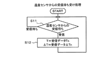
図5は、温度予測部3による受信待ち受け処理のフローチャートである。温度予測部3は、温度センサ部4からの温度Tn及び傾きΔTnの受信待ちをしており(S11)、それらを受信すると、温度Tnを変数Tに代入すると共に、傾きΔTnを変数ΔTに代入して(S12)ステップS11に戻る。
FIG. 5 is a flowchart of reception standby processing by the
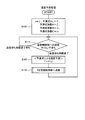
図6は、温度予測部3による温度予測処理のフローチャートである。温度予測部3は、ステップS13において変数TとΔTとを、それぞれ任意の値γ,δに初期設定する。それから、空調制御部2への送信時間待ちをする(S14)。送信時間間隔は、例えば1分程度とする。送信時間になると、温度予測を以下の式で行う(S15)。
T=T+ΔT
そして、予測した温度Tを空調制御部2に送信すると(S16)ステップS14に戻る。
FIG. 6 is a flowchart of the temperature prediction process by the
T = T + ΔT
Then, when the predicted temperature T is transmitted to the air
以上のように処理を行う結果、温度センサ部4から温度予測部3への無線による送信は、温度変化の傾きが大きく変化したことでステップS7を実行するタイミングとなる。そして、温度予測部3は、温度センサ部4からの温度データの受信の有無にかかわらず、一定の周期,例えば1分間隔で温度情報Tを空調制御部2に送信する。それ受けて、空調制御部2も1分間隔で空調機1を制御する。空調機1は、各部屋の空調制御量を満たす能力を得るためにコンプレッサを駆動して熱サイクルを動作させる。空調制御部2は、各部屋の制御量に応じた指令を温度予測部3に伝達し、温度予測部3は、各部屋のダンパ5の開度を制御する。
As a result of performing the processing as described above, the wireless transmission from the
以上のように本実施形態によれば、空調制御部2は、複数の区域に対して個別に空調可能なダンパ5に対して、各区域それぞれの空調に関する制御内容を指示する。温度センサ部4は、複数の区域にそれぞれ配置され、サンプリング周期毎に温度Tsampを検出すると共に温度変化の傾きΔTnの変化量ΔΔTを求める。そして、傾きの変化量ΔΔTが許容範囲を超えると、検出した温度Tn及び温度変化の傾きΔTnを無線通信により送信する。温度予測部3は、それらを受信すると、その受信時点以降の経過時間に応じた各区域の温度を予測した温度情報を生成し、空調制御部2に送信する。
As described above, according to the present embodiment, the air
このように構成すれば、温度センサ部4は、対応する区域の温度が比較的大きく変化した場合にだけ温度予測部3に対して温度等を送信するので、無線通信を行う頻度を低下させることができる。また温度予測部3は、温度センサ部4からの送信が行われない期間においても、既に受信した温度及び温度変化の傾きに基づいて、対応する区域の温度を予測した温度情報Tを空調制御部2に送信できる。したがって、空調制御部2は、その温度情報により各区域の空調ユニットに制御内容を指示できる。
With this configuration, the
そして、対応する区域の温度が大きく変化すれば、温度センサ部4より温度等が送信されてそれらの情報が更新され、温度予測部3は、更新された情報に基づいて新たに温度予測を行う。したがって、温度センサ部4が無線通信を行う頻度を低下させても、空調制御の精度を低下させることなく維持できる。
(第2実施形態)
Then, if the temperature in the corresponding area changes significantly, the
(Second Embodiment)
以下、第1実施形態と同一部分には同一符号を付して説明を省略し、異なる部分について説明する。図7に示すように、第2実施形態の温度センサ部21は、温度予測部3と同様に自身も温度予測を行う。図8に示すように、ステップS1に替わるステップS21において、温度センサ部21は、予測温度Tp及び予測温度変化の傾きΔTpと、現周期の検出温度Tn及び温度変化の傾きΔTnと、1周期前の予測温度Tp-1とを、それぞれ任意の値A,B,C,D,Eに初期設定する。それから、ステップS2及びS3を実行すると、温度変化の傾きΔTnを用いて次式により温度予測を行う(S22)。
Tp=Tp-1+ΔTn
Hereinafter, the same parts as those in the first embodiment are designated by the same reference numerals, description thereof will be omitted, and different parts will be described. As shown in FIG. 7, the temperature sensor unit 21 of the second embodiment also predicts the temperature by itself in the same manner as the
Tp = Tp-1 + ΔTn
次に、予測温度Tpと、ステップS3で検出した温度Tnとの差ΔTpnを求める(S23)。
ΔTpn=Tp−Tn
そして、温度差ΔTpnが許容範囲内にあるか否かを、以下のように判断する(S24)。
α<ΔTpn<β
これらの閾値α,βについても任意に定める。温度差ΔTpnが許容範囲内にあれば(YES)、予測温度の変数Tpを変数Tp-1に代入して(S25)ステップS2に戻る。
Next, the difference ΔTpn between the predicted temperature Tp and the temperature Tn detected in step S3 is obtained (S23).
ΔTpn = Tp-Tn
Then, it is determined as follows whether or not the temperature difference ΔTpn is within the permissible range (S24).
α <ΔTpn <β
These thresholds α and β are also arbitrarily determined. If the temperature difference ΔTpn is within the permissible range (YES), the variable Tp of the predicted temperature is substituted into the variable Tp-1 (S25), and the process returns to step S2.
一方、ステップS24において温度差ΔTpnが許容範囲外にあれば(NO)、ステップS4,S7を実行してからステップS25に移行する。尚、温度予測部3が行う処理内容は第2実施形態と同じである。
On the other hand, if the temperature difference ΔTpn is out of the permissible range in step S24 (NO), steps S4 and S7 are executed before proceeding to step S25. The processing content performed by the
以上のように第2実施形態によれば、温度センサ部21も、自身が求めた温度変化の傾きΔTnに基づいて検出される温度を予測する。そして、実際に検出された温度Tnと予測した温度Tpとの差ΔTpnが一定の範囲を超えると、その時点の温度変化の傾きΔTnを求めて検出した温度Tnと共に無線通信により送信する。温度予測部3は、第1実施形態と同様に、受信時点以降の経過時間に応じた各区域の温度を予測した温度情報を生成し、空調制御部2に送信する。
As described above, according to the second embodiment, the temperature sensor unit 21 also predicts the temperature to be detected based on the slope ΔTn of the temperature change obtained by itself. Then, when the difference ΔTpn between the actually detected temperature Tn and the predicted temperature Tp exceeds a certain range, the slope ΔTn of the temperature change at that time is obtained and transmitted by wireless communication together with the detected temperature Tn. Similar to the first embodiment, the
すなわち、予測した温度Tpと実際に検出された温度Tnとの差が大きくなれば、温度予測部3が予測に使用している情報を更新する必要があることになる。そこで、温度センサ部21がその場合に無線通信を行い、温度等の情報Tn,ΔTnを温度予測部3に送信すれば、温度予測部3は適切なタイミングで予測に使用する情報を更新できる。したがって、温度センサ部21が無線通信を行う頻度を低下させても、空調制御の精度を維持できる。
(第3実施形態)
That is, if the difference between the predicted temperature Tp and the actually detected temperature Tn becomes large, it is necessary to update the information used by the
(Third Embodiment)
図9に示すように、第3実施形態の温度センサ部31は、第2実施形態のように温度予測を行う際に使用する、過去の温度変化の特性に適合するように選択された複数の予測式を予め記憶している。そして、それらを適宜選択して温度予測を行う。図10に示すように、温度センサ部31は、最初のステップS31でステップS21と同様に初期設定を行うが、第3実施形態では変数ΔTn,Tp-1は使用しない。それから、第2実施形態と同様にステップS2及びS3を実行すると、予測式F(t)を用いて温度予測を行う(S32)。 As shown in FIG. 9, the temperature sensor unit 31 of the third embodiment has a plurality of selected temperature sensor units 31 selected to match the characteristics of past temperature changes used when performing temperature prediction as in the second embodiment. The prediction formula is stored in advance. Then, they are appropriately selected to predict the temperature. As shown in FIG. 10, the temperature sensor unit 31 makes initial settings in the first step S31 in the same manner as in step S21, but the variables ΔTn and Tp-1 are not used in the third embodiment. Then, when steps S2 and S3 are executed in the same manner as in the second embodiment, the temperature is predicted using the prediction formula F (t) (S32).
図11から図14には、使用する予測式の一例を示している。図11に示すのは2次関数を用いたもので、気密性が比較的高く、比較的広い部屋に適合する温度変化パターンであり、は以下のようになる。
Tp=Ax2+Bx+C …(1)
11 to 14 show an example of the prediction formula to be used. FIG. 11 shows a temperature change pattern using a quadratic function, which has a relatively high airtightness and is suitable for a relatively large room, and is as follows.
Tp = Ax 2 + Bx + C ... (1)
図12に示すのは1次関数を用いたもので、気密性が比較的高く、比較的狭い部屋に適合する温度変化パターンであり、温度が上昇する過程の予測式は以下のようになる。
Tp=Ax+C …(2)
FIG. 12 shows a temperature change pattern using a linear function, which is relatively airtight and suitable for a relatively small room, and the prediction formula for the process of temperature rise is as follows.
Tp = Ax + C ... (2)
図13に示すのは正弦関数を用いたもので、気密性が比較的低く、比較的広い部屋に適合する温度変化パターンであり、予測式は以下のようになる。
Tp=Asin(Bθ)+C …(3)
FIG. 13 shows a temperature change pattern using a sine function, which has relatively low airtightness and is suitable for a relatively large room, and the prediction formula is as follows.
Tp = Asin (Bθ) + C ... (3)
図14に示すのは、気密性が比較的低く、比較的狭い部屋に適合するもので温度が変化しないパターンであり、予測式は以下のようになる。
Tp=C …(4)
尚、係数A,B,Cは、各予測式毎に設定される値である。
FIG. 14 shows a pattern in which the airtightness is relatively low, which is suitable for a relatively small room and the temperature does not change, and the prediction formula is as follows.
Tp = C ... (4)
The coefficients A, B, and C are values set for each prediction formula.
再び、図10を参照する。第2実施形態と同様にステップS23及びS24を実行し、温度差ΔTpnが許容範囲内にあれば(YES)ステップS2に戻る。温度差ΔTpnが許容範囲外にあれば(NO)、ステップS32で用いた予測式とは異なる予測式F(t)を選択し、選択した予測式に対応する係数A,B,Cを決定する(S33)。それから、温度Tnと、選択した予測式を特定する番号と、対応する係数とを温度予測部32に送信すると(S34)ステップS2に戻る。
Again, see FIG. Steps S23 and S24 are executed in the same manner as in the second embodiment, and if the temperature difference ΔTpn is within the permissible range (YES), the process returns to step S2. If the temperature difference ΔTpn is out of the permissible range (NO), a prediction formula F (t) different from the prediction formula used in step S32 is selected, and the coefficients A, B, and C corresponding to the selected prediction formula are determined. (S33). Then, when the temperature Tn, the number specifying the selected prediction formula, and the corresponding coefficient are transmitted to the
ここで、ステップS32で最初に使用する予測式F(t)は、上述した4つの何れでも良い。また、ステップS33で次に選択する予測式F(t)も、その他の何れでも良い。例えば、最初に(1)式を選択し、以降(2)→(3)→(4)→…の順で選択しても良い。また、経験的に、(2)式が適合する部屋が多いと判断した際には、最初に(2)式を選択しても良い。 Here, the prediction formula F (t) first used in step S32 may be any of the four described above. Further, the prediction formula F (t) selected next in step S33 may be any other. For example, the equation (1) may be selected first, and then (2) → (3) → (4) → ... Further, when it is empirically determined that there are many rooms to which the formula (2) is suitable, the formula (2) may be selected first.
図15に示すように、温度予測部32は、ステップS11において温度センサ部31から温度Tn等を受信すると、「温度変数T」,「予測式No.」,「予測式係数A,B,C」に、それぞれ受信したデータを設定する(S41)。それから、「予測式No.」を対応する予測式F(t)に変換すると(S42)、「変数T」から予測式F(t)の現在時間tを決定する(S43)。
As shown in FIG. 15, when the
図16に示す温度予測処理では、温度予測部32は、「時間変数t」,「予測式No.」,「予測式係数A,B,C」を、それぞれ任意の値γ,δ,ζ,η,ωに初期設定する(S44)。それから、ステップS14で送信タイミング待ちをし、送信タイミングになると予測式F(t)を用いて温度予測を行う(S45)。それから、ステップS16を実行する。
In the temperature prediction process shown in FIG. 16, the
以上のように第3実施形態によれば、温度センサ部31は、サンプリング周期毎に温度を検出すると、予め記憶した複数の温度変化の予測式F(t)から選択したものを用いて温度の予測を行う。そして、実際に検出した温度Tnと予測した温度Tpとの差ΔTpnが一定の範囲を超えると、別の温度予測式F(t)を再度選択して、検出した温度Tnと使用している予測式F(t)の情報とを送信する。 As described above, according to the third embodiment, when the temperature sensor unit 31 detects the temperature for each sampling cycle, the temperature sensor unit 31 uses a temperature selected from a plurality of temperature change prediction formulas F (t) stored in advance. Make a prediction. Then, when the difference ΔTpn between the actually detected temperature Tn and the predicted temperature Tp exceeds a certain range, another temperature prediction formula F (t) is selected again, and the detected temperature Tn and the predicted temperature Tn are used. The information of the formula F (t) is transmitted.
温度予測部32は、それらを受信すると、受信時点以降の経過時間に応じた各区域の温度を予測式F(t)を用いて予測し、温度情報として空調制御部2に送信する。これにより、温度予測部32は、適切な予測式を用いて温度を予測できる。この場合、予測式として例えば(1)〜(4)式を用いることで、空調対象となる区域の広さや気密性に応じて、それぞれに適合する予測式によって温度を適切に予測できる。
When the
本発明は上記した、又は図面に記載した実施形態にのみ限定されるものではなく、以下のような変形又は拡張が可能である。
予測式は例示したものに限ることはなく、より複雑な関数を用いて予測しても良い。
また、予測式を3つ以下,又は5つ以上使用しても良い。
空調制御の対象とする区域は、「2」又は「4」以上でも良い。
The present invention is not limited to the embodiments described above or in the drawings, and the following modifications or extensions are possible.
The prediction formula is not limited to the example, and may be predicted using a more complicated function.
Moreover, you may use 3 or less or 5 or more prediction formulas.
The area targeted for air conditioning control may be "2" or "4" or more.
図面中、1は空調機、2は空調制御部、3は温度予測部、4は温度センサ部、5はダンパを示す。 In the drawing, 1 is an air conditioner, 2 is an air conditioning control unit, 3 is a temperature prediction unit, 4 is a temperature sensor unit, and 5 is a damper.
Claims (7)
この空調ユニットに対して、前記複数の区域それぞれの空調に関する制御内容を指示する空調制御部と、
前記複数の区域にそれぞれ配置され、サンプリング周期毎に温度を検出すると共に温度変化の傾きの変化量を求め、前記変化量の大きさが許容範囲を超えると、検出した温度及び温度変化の傾きを無線通信により送信する温度センサ部と、
前記温度及び温度変化の傾きを受信すると、その受信時点以降の経過時間に応じた各区域の温度を予測した温度情報を生成し、前記空調制御部に送信する温度予測部とを備える全館空調システム。 An air conditioning unit that can individually air-condition multiple areas,
An air-conditioning control unit that instructs the air-conditioning unit to control the air-conditioning in each of the plurality of areas.
They are arranged in each of the plurality of areas, and the temperature is detected for each sampling cycle and the amount of change in the slope of the temperature change is obtained. When the magnitude of the amount of change exceeds the allowable range, the detected temperature and the slope of the temperature change are calculated. The temperature sensor unit that transmits by wireless communication and
When the temperature and the slope of the temperature change are received, the whole building air conditioning system including a temperature prediction unit that generates temperature information that predicts the temperature of each area according to the elapsed time after the reception time and transmits the temperature information to the air conditioning control unit. ..
この空調ユニットに対して、前記複数の区域それぞれの空調に関する制御内容を指示する空調制御部と、
前記複数の区域にそれぞれ配置され、サンプリング周期毎に温度を検出すると共に温度変化の傾きを求め、前記傾きに基づいて検出される温度を予測し、実際に検出した温度と予測した温度との差が一定の範囲を超えると、その時点の温度変化の傾きを求めて検出した温度と共に無線通信により送信する温度センサ部と、
前記温度及び温度変化の傾きを受信すると、その受信時点以降の経過時間に応じた各区域の温度を予測した温度情報を生成し、前記空調制御部に送信する温度予測部とを備える全館空調システム。 An air conditioning unit that can individually air-condition multiple areas,
An air-conditioning control unit that instructs the air-conditioning unit to control the air-conditioning in each of the plurality of areas.
They are arranged in each of the plurality of areas, detect the temperature for each sampling cycle, obtain the slope of the temperature change, predict the temperature detected based on the slope, and the difference between the actually detected temperature and the predicted temperature. When the temperature exceeds a certain range, the temperature sensor unit that obtains the slope of the temperature change at that time and transmits it by wireless communication together with the detected temperature.
When the temperature and the slope of the temperature change are received, the whole building air conditioning system including a temperature prediction unit that generates temperature information that predicts the temperature of each area according to the elapsed time after the reception time and transmits the temperature information to the air conditioning control unit. ..
この空調ユニットに対して、前記複数の区域それぞれの空調に関する制御内容を指示する空調制御部と、
前記複数の区域にそれぞれ配置され、サンプリング周期毎に温度を検出し、予め記憶した複数の温度変化の予測式から選択したものを用いて、検出される温度の予測を行い、実際に検出した温度と予測した温度との差が一定の範囲を超えると、別の温度予測式を再度選択して、検出した温度と使用している予測式の情報とを送信し、
前記温度及び予測式の情報を受信すると、その受信時点以降の経過時間に応じた各区域の温度を、前記予測式を用いて予測した温度情報を生成し、前記空調制御部に送信する温度予測部とを備える全館空調システム。 An air conditioning unit that can individually air-condition multiple areas,
An air-conditioning control unit that instructs the air-conditioning unit to control the air-conditioning in each of the plurality of areas.
The temperature is predicted for each of the plurality of areas, the temperature is detected for each sampling cycle, the temperature to be detected is predicted using the one selected from the plurality of temperature change prediction formulas stored in advance, and the actually detected temperature is obtained. When the difference between the temperature and the predicted temperature exceeds a certain range, another temperature prediction formula is selected again, and the detected temperature and the information of the prediction formula used are transmitted.
When the information of the temperature and the prediction formula is received, the temperature of each area corresponding to the elapsed time after the reception time is generated by using the prediction formula, and the temperature prediction is transmitted to the air conditioning control unit. The entire building air conditioning system equipped with a department.
Priority Applications (2)
| Application Number | Priority Date | Filing Date | Title |
|---|---|---|---|
| JP2017238619A JP6958314B2 (en) | 2017-12-13 | 2017-12-13 | Whole building air conditioning system |
| US16/185,714 US10767889B2 (en) | 2017-12-13 | 2018-11-09 | Central air conditioning system |
Applications Claiming Priority (1)
| Application Number | Priority Date | Filing Date | Title |
|---|---|---|---|
| JP2017238619A JP6958314B2 (en) | 2017-12-13 | 2017-12-13 | Whole building air conditioning system |
Publications (2)
| Publication Number | Publication Date |
|---|---|
| JP2019105411A JP2019105411A (en) | 2019-06-27 |
| JP6958314B2 true JP6958314B2 (en) | 2021-11-02 |
Family
ID=66734640
Family Applications (1)
| Application Number | Title | Priority Date | Filing Date |
|---|---|---|---|
| JP2017238619A Active JP6958314B2 (en) | 2017-12-13 | 2017-12-13 | Whole building air conditioning system |
Country Status (2)
| Country | Link |
|---|---|
| US (1) | US10767889B2 (en) |
| JP (1) | JP6958314B2 (en) |
Families Citing this family (1)
| Publication number | Priority date | Publication date | Assignee | Title |
|---|---|---|---|---|
| CN113654200A (en) * | 2021-07-29 | 2021-11-16 | 中国水利水电第六工程局有限公司 | Temperature control system for steel pipe production workshop |
Family Cites Families (7)
| Publication number | Priority date | Publication date | Assignee | Title |
|---|---|---|---|---|
| JP4668770B2 (en) * | 2005-11-09 | 2011-04-13 | 株式会社山武 | Wireless air conditioning control system and air conditioning controller |
| JP2011059739A (en) * | 2009-09-04 | 2011-03-24 | Fujitsu Ltd | Temperature predicting apparatus, temperature predicting method, and temperature predicting program |
| JP5373532B2 (en) * | 2009-10-06 | 2013-12-18 | アズビル株式会社 | Air conditioning operation device and air conditioning operation method |
| JP4854779B2 (en) * | 2009-12-09 | 2012-01-18 | シャープ株式会社 | Air conditioner, expansion valve opening control method and program |
| US8725307B2 (en) * | 2011-06-28 | 2014-05-13 | Schneider Electric It Corporation | System and method for measurement aided prediction of temperature and airflow values in a data center |
| US8600561B1 (en) * | 2012-09-30 | 2013-12-03 | Nest Labs, Inc. | Radiant heating controls and methods for an environmental control system |
| JP6160945B2 (en) * | 2013-01-11 | 2017-07-12 | パナソニックIpマネジメント株式会社 | Room temperature estimation device, program |
-
2017
- 2017-12-13 JP JP2017238619A patent/JP6958314B2/en active Active
-
2018
- 2018-11-09 US US16/185,714 patent/US10767889B2/en active Active
Also Published As
| Publication number | Publication date |
|---|---|
| US20190178525A1 (en) | 2019-06-13 |
| US10767889B2 (en) | 2020-09-08 |
| JP2019105411A (en) | 2019-06-27 |
Similar Documents
| Publication | Publication Date | Title |
|---|---|---|
| US20210088239A1 (en) | Thermostat temperature compensation modeling | |
| EP1932065B1 (en) | Arrangement of microsystems for comfort control | |
| JP6415596B2 (en) | Air control system | |
| JPWO2016035121A1 (en) | Air conditioning system control apparatus and air conditioning system control method | |
| JP6429779B2 (en) | Air conditioning control system | |
| US9625170B2 (en) | Efficient combination of ambient air and heating, ventilating, and air conditioning (HVAC) system | |
| JP6419497B2 (en) | Air conditioning control device, air conditioning control method, and program | |
| EP3039502B1 (en) | Method for temperature control | |
| JP6958314B2 (en) | Whole building air conditioning system | |
| JP2017101871A (en) | Air conditioner | |
| WO2015141118A1 (en) | Air-blowing control system and air-blowing control program | |
| JP6005980B2 (en) | Air conditioner system | |
| JP5996932B2 (en) | Air conditioner | |
| JP6641252B2 (en) | Air conditioner | |
| KR20150105839A (en) | Air-conditioner and method | |
| KR101698790B1 (en) | Air conditioner and method | |
| JP7126569B2 (en) | air conditioning control system | |
| JP2017089996A (en) | Air-conditioning control system, air-conditioning control method and control program | |
| JP2013231523A (en) | Air conditioning control device and method | |
| WO2021014500A1 (en) | Air conditioning device, control device, information processing device, and information processing method | |
| JP2021071243A (en) | Air conditioning system and air conditioner | |
| US20150083812A1 (en) | Temperature adjustment system and method | |
| JP2007003084A (en) | Remote control device | |
| JP2021050862A (en) | Air conditioner | |
| US11506215B1 (en) | Fan with automatic thermal comfort control |
Legal Events
| Date | Code | Title | Description |
|---|---|---|---|
| A621 | Written request for application examination |
Free format text: JAPANESE INTERMEDIATE CODE: A621 Effective date: 20200820 |
|
| A977 | Report on retrieval |
Free format text: JAPANESE INTERMEDIATE CODE: A971007 Effective date: 20210624 |
|
| A131 | Notification of reasons for refusal |
Free format text: JAPANESE INTERMEDIATE CODE: A131 Effective date: 20210706 |
|
| A521 | Written amendment |
Free format text: JAPANESE INTERMEDIATE CODE: A523 Effective date: 20210818 |
|
| TRDD | Decision of grant or rejection written | ||
| A01 | Written decision to grant a patent or to grant a registration (utility model) |
Free format text: JAPANESE INTERMEDIATE CODE: A01 Effective date: 20210907 |
|
| A61 | First payment of annual fees (during grant procedure) |
Free format text: JAPANESE INTERMEDIATE CODE: A61 Effective date: 20210920 |
|
| R150 | Certificate of patent or registration of utility model |
Ref document number: 6958314 Country of ref document: JP Free format text: JAPANESE INTERMEDIATE CODE: R150 |