JP6957840B2 - Hairline film fluff removal device and method - Google Patents
Hairline film fluff removal device and method Download PDFInfo
- Publication number
- JP6957840B2 JP6957840B2 JP2016136649A JP2016136649A JP6957840B2 JP 6957840 B2 JP6957840 B2 JP 6957840B2 JP 2016136649 A JP2016136649 A JP 2016136649A JP 2016136649 A JP2016136649 A JP 2016136649A JP 6957840 B2 JP6957840 B2 JP 6957840B2
- Authority
- JP
- Japan
- Prior art keywords
- film
- fluff
- work
- hairline
- cleaning
- Prior art date
- Legal status (The legal status is an assumption and is not a legal conclusion. Google has not performed a legal analysis and makes no representation as to the accuracy of the status listed.)
- Expired - Fee Related
Links
Images
Landscapes
- Cleaning In General (AREA)
- Cleaning By Liquid Or Steam (AREA)
Description
この発明はヘアライン加工された樹脂フィルムの表面に残留ないしは付着している毛羽(ヒゲ)を除去する装置および方法に関する。 The present invention relates to an apparatus and method for removing fluff (whiskers) remaining or adhering to the surface of a hairline-processed resin film.
合成樹脂(プラスチック)フィルム表面へのヘアライン加工は,フィルム表面に研磨,切削,ブラッシング等により細かい条痕(ヘアライン)を付けるものである。このため,削り屑ないしは粉がフィルム表面に付着したり,糸状の削り屑が切れずに残ってしまう。 Hairline processing on the surface of a synthetic resin (plastic) film is to make fine streaks (hairlines) on the film surface by polishing, cutting, brushing, or the like. For this reason, shavings or powder adhere to the film surface, and thread-like shavings remain without being cut.
特許文献1に記載のヘアライン模様付フィルム製造装置では,加工時にフィルムに発生する静電気を除去し,同時にフィルム面に付着している研磨粉等を除去するために水洗している。しかしながら,水洗はシャワーで水をフィルム面に吹き付けるだけで,フィルムから完全に分離している削り屑は除去できるが,切れずに残った削り屑やヘアラインの凹部に埋没した削り屑,粉等(これらを毛羽(バリ,ヒゲ)という)は水流だけでは除去できず,残留する。 In the hairline patterned film manufacturing apparatus described in Patent Document 1, the film is washed with water in order to remove static electricity generated in the film during processing and at the same time to remove polishing powder and the like adhering to the film surface. However, in washing with water, shavings that are completely separated from the film can be removed by simply spraying water on the film surface with a shower, but shavings that remain uncut, shavings that are buried in the recesses of the hairline, powder, etc. ( These are called fluff (burrs, mustaches)) that cannot be removed by water flow alone and remain.
特許文献2に記載のヘアライン意匠加飾シート製造方法は,可撓性が失なわれる程度に脆化点付近まで強制冷却された状態のプラスチックシートの表面にヘアライン目を形成し,その後,外部の熱を吸収させることにより,可撓性を復元させるものである。プラスチックシートを冷却してその弾性率を大幅に減少させてヘアライン加工を施しているので,加工時に糸状の削り屑が残らないと記載されている。しかしながら,この製造方法ではプラスチックフィルムを強制冷却するという工程が必要であり,冷却によりフィルムは脆弱になるので,加工時に破損する可能性がある。
The hairline design decorative sheet manufacturing method described in
この発明は,フィルムに特許文献2に記載のような温度変化を加えることなく,毛羽を除去できる毛羽除去装置および方法を提供するものである。
The present invention provides a fluff removing device and a method capable of removing fluff without applying a temperature change as described in
この発明による毛羽除去装置は,少なくとも一面にヘアライン加工が施されたフィルム状ワークの搬送路に沿って順に配置された毛羽除去部,洗浄部および乾燥部を含む。毛羽除去部は,砥粒を含む毛羽除去液を溜めた毛羽除去液槽,および前記毛羽除去液槽内に導かれたフィルム状ワークのヘアライン加工面に不織布を押し当てる除去具を備えている。洗浄部は,洗浄液が溜められた洗浄槽内に導かれたフィルム状ワークの表面に付着した砥粒等の付着物を除去するものである。乾燥部は付着物が除去されたフィルム状ワークを乾燥させるものである。 The fluff removing device according to the present invention includes a fluff removing portion, a cleaning portion, and a drying portion which are sequentially arranged along a transport path of a film-like work having a hairline processed on at least one surface. The fluff removing portion includes a fluff removing liquid tank in which a fluff removing liquid containing abrasive grains is stored, and a removing tool for pressing a non-woven fabric against the hairline-processed surface of the film-like work guided into the fluff removing liquid tank. The cleaning unit removes deposits such as abrasive grains adhering to the surface of the film-like work guided into the cleaning tank in which the cleaning liquid is stored. The drying portion dries the film-like work from which the deposits have been removed.
この発明による毛羽除去方法では,少なくとも一面にヘアライン加工が施されたフィルム状ワークの搬送路に沿って毛羽除去工程,洗浄工程および乾燥工程が順に設ける。毛羽除去工程では,フィルム状ワークを,砥粒を含む毛羽除去液を溜めた毛羽除去液槽内に導き,そのヘアライン加工面に不織布を押し当てて毛羽を除去する。洗浄工程では,フィルム状ワークを,洗浄液が溜められた洗浄槽内に導き,その表面に付着した砥粒等の付着物を除去する。乾燥工程では付着物が除去されたフィルム状ワークを乾燥させる。 In the fluff removing method according to the present invention, a fluff removing step, a washing step, and a drying step are sequentially provided along a transport path of a film-like work having hairline processing on at least one surface. In the fluff removing step, the film-like work is guided into a fluff removing liquid tank in which a fluff removing liquid containing abrasive grains is stored, and a non-woven fabric is pressed against the hairline processed surface to remove the fluff. In the cleaning process, the film-like work is guided into a cleaning tank in which the cleaning liquid is stored, and deposits such as abrasive grains adhering to the surface thereof are removed. In the drying step, the film-like work from which the deposits have been removed is dried.
一実施態様では,前記除去具が不織布が巻き付けられた毛羽除去ローラであり,フィルム状ワークのヘアライン加工面が不織布に接して搬送されていく。また,前記毛羽除去部がフィルム状ワークの搬送部を備える。好ましい実施態様では前記毛羽除去ローラが固定される,またはフィルム状ワーク搬送方向とは逆方向に回転させられる。 In one embodiment, the removing tool is a fluff removing roller around which a non-woven fabric is wound, and the hairline-processed surface of the film-like work is conveyed in contact with the non-woven fabric. Further, the fluff removing portion includes a transport portion for the film-like work. In a preferred embodiment, the fluff removing roller is fixed or rotated in a direction opposite to the film-like work transfer direction.
さらに他の実施態様では,前記洗浄部がフィルム状ワークの搬送部,および洗浄槽内に配置され,その表面に不織布が巻き付けられた洗浄ローラを備える。好ましくは,毛羽除去ローラの不織布および洗浄ローラの不織布にはナノファイバーを用いたものを使用し,その繊維径は 500nm以下が好ましい。 In still another embodiment, the cleaning portion is provided in a transport portion of the film-shaped work and a cleaning roller in which the non-woven fabric is wound around the surface thereof. Preferably, nanofibers are used for the non-woven fabric of the fluff removing roller and the non-woven fabric of the cleaning roller, and the fiber diameter thereof is preferably 500 nm or less.
好ましい実施態様では毛羽除去液内の砥粒の粒径はヘアラインの線幅の1/2以下である。 In a preferred embodiment, the particle size of the abrasive grains in the fluff removing liquid is 1/2 or less of the line width of the hairline.
この発明によると,ヘアライン加工が施されたフィルム状ワークに残った毛羽,またはヘアラインの溝もしくは微細な凹部に埋設した毛羽は,毛羽除去部において,フィルム状ワークが砥粒を含む毛羽除去液内に導かれ,不織布が押し当てられた状態で搬送されていくことにより,不織布とフィルム状ワークとの間に侵入した砥粒によって擦られ,切断され,引きちぎられてフィルム状ワークから分離される。フィルム状ワークに付着した分離毛羽,砥粒等は次の洗浄部で洗浄液内で落される。このようにして毛羽が除去され,かつ洗浄されたフィルム状ワークは乾燥部で乾燥される。 According to the present invention, the fluff remaining in the film-like work subjected to the hairline processing, or the fluff embedded in the groove or the fine recess of the hairline, is formed in the fluff removing liquid in which the film-like work contains abrasive grains in the fluff removing portion. By being guided by the non-woven fabric and being conveyed in a pressed state, the non-woven fabric is rubbed, cut, and torn off by the abrasive grains that have penetrated between the non-woven fabric and the film-like work, and separated from the film-like work. Separation fluff, abrasive grains, etc. adhering to the film-like work are removed in the cleaning liquid at the next cleaning section. The film-like work from which the fluff has been removed and washed in this way is dried in the dry portion.
このようにして,この発明によると,ヘアライン加工でフィルム状ワークに残った削り屑等はすっかり除去される。また,無理な温度変化(特に冷却)を与えないからフィルムが割れてしまうこともない。 In this way, according to the present invention, the shavings and the like remaining on the film-like work by the hairline processing are completely removed. Moreover, since the film is not subjected to an unreasonable temperature change (particularly cooling), the film does not crack.
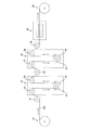
図1はヘアラインフィルムの毛羽除去装置の全体的構成を示すものである。 FIG. 1 shows the overall configuration of a fluff removing device for a hairline film.
ヘアラインフィルムの毛羽除去装置は,フィルム状ワーク繰出し部10,毛羽除去部20,洗浄部30,乾燥部40およびフィルム状ワーク巻取り部50から構成され,これらが上記の順にフィルム状ワークの搬送路に沿って配置されている。
The hairline film fluff removing device is composed of a film-like
フィルム状ワークFWは,一面にヘアライン加工が施された合成樹脂フィルム(シート)である。この毛羽除去装置はあらゆる種類(素材)の合成樹脂フィルムに適用できる。フィルム状ワーク繰出し部10は,フィルム状ワークFWが巻回された繰出しロールから,フィルム状ワークFWを繰出すものである。フィルム状ワークFWが巻回された繰出しロールは必ずしも積極的にフィルム状ワークFWを繰出す方向に回転しなくても,次に述べる搬送装置によりフィルム状ワークFWが搬送されるので,これに伴って従動的に回転するものでもよい。図1に図示の例では,フィルム状ワークFWのヘアライン加工された面を表側にしてロールに巻回されている。
The film-like work FW is a synthetic resin film (sheet) having a hairline finish on one surface. This fluff removing device can be applied to all kinds (materials) of synthetic resin films. The film-shaped
フィルム状ワークFWの搬送装置は,フィルム状ワーク繰出し部10と毛羽除去部20との間に配置されたローラ11,毛羽除去部20内に配置された2つのローラ21,22(搬送部),毛羽除去部20と洗浄部30との間に配置されたローラ25,洗浄部30内に配置されたローラ31,32(搬送部),および洗浄部30と乾燥部40との間に配置されたローラ35を含み,必要に応じて,フィルム状ワーク繰出し部10の繰出しロールおよびフィルム状ワーク巻取り部50の巻取りロールが搬送装置に加えられる。上記のローラおよびロールのいずれか,少なくとも1つ,または適数個が回転駆動され,フィルム状ワークFWを,繰出し部10から毛羽除去部20,洗浄部30および乾燥部40を経て巻取り部50まで搬送する(矢印で示す方向)。
The transport device for the film-shaped work FW includes a roller 11 arranged between the film-shaped
毛羽除去部20は,上記の搬送ローラ21,22に加えて,毛羽除去ローラ23(除去具)と毛羽除去液槽24とを含む。毛羽除去ローラ23は金属製(または合成樹脂製)であり,その表面に不織布が巻付けられ,かつ固定されている。毛羽除去液は砥粒を含む液体(たとえば水)であり,毛羽除去液槽24に満たされている(溜められている)。毛羽除去ローラ23は,好ましくはその半分以上が毛羽除去液内に入っている。フィルム状ワークFWはローラ21から毛羽除去ローラ23に掛けられ,さらにローラ22に向っている。したがって,フィルム状ワークFWは毛羽除去ローラ23が毛羽除去液内に浸っている範囲程度,またはそれ以上の範囲でヘアライン加工された面が毛羽除去ローラ23の不織布に強く接している。毛羽除去ローラ23は固定されているか,またはフィルム状ワークFWの搬送方向とは逆方向に回転させられる。加工されたヘアラインの線幅の1/2以下の粒径を持つ砥粒を用いることが好ましい。たとえば,1〜5μmの粒径の砥粒を用いた場合には,線幅10μm以上のヘアラインが形成されたフィルム状ワークの毛羽除去が可能である。
The
洗浄部30は,上記の搬送ローラ31,32に加えて,洗浄ローラ33と洗浄槽34とを含む。洗浄ローラ33は金属製または合成樹脂製であり,その表面に不織布が巻付けられ,かつ固定されている。洗浄槽34内には洗浄液(たとえば水)が満たされている(溜められている)。洗浄ローラ33は,好ましくはその半分以上が洗浄槽34内に入っている。フィルム状ワークFWはローラ31から洗浄ローラ23に掛けられ,さらにローラ32に向っている。したがって,フィルム状ワークFWは洗浄ローラ33が洗浄液内に浸っている範囲程度,またはそれ以上の範囲でヘアライン加工された面が洗浄ローラ33の不織布に強く接している。洗浄ローラ33はフィルム状ワークFWの進行とともに回転してもよいし,毛羽除去ローラ23と同じように,固定,または逆回転させてもよい。毛羽除去ローラ23および洗浄ローラ33に巻付ける不織布には,いわゆるナノファイバーを使用したものを使用し,その繊維径は500nm以下が好ましい。
The
乾燥部40は熱または風により乾燥する乾燥機を含む。
The drying
フィルム状ワーク巻取り部50は,乾燥部40を経て搬送されるフィルム状ワークを回転駆動される巻取りロールに巻取るものである。
The film-shaped
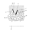
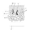
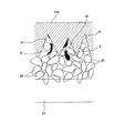
図2から図4を参照して,上記の毛羽除去装置による毛羽除去作用について説明する。毛羽とは,図2に示すように,ヘアライン加工によりフィルム状ワークFWの一面に形成されたヘアライン(細かい凹溝)H内,またはその付近に残留,埋設した削り屑ないしは粉である。 The fluff removing action of the above fluff removing device will be described with reference to FIGS. 2 to 4. As shown in FIG. 2, the fluff is shavings or powder remaining or buried in or near the hairline (fine concave groove) H formed on one surface of the film-like work FW by the hairline processing.
毛羽除去部20において,毛羽除去液槽24の毛羽除去液内には多くの砥粒26が含まれており,毛羽除去ローラ23には不織布27が巻き付けられ,かつ固定されている。フィルム状ワークFWはそのヘアラインHが形成された面が毛羽除去ローラ23に巻き付けられた不織布27に圧接している。毛羽除去液内の砥粒26は,図2に示すように細かい繊維を含む不織布に捉えられ,不織布とフィルム状ワークFW,特にヘアラインHの溝ないし凹部内に入り込む。毛羽除去ローラ23は固定または逆回転しているので,フィルム状ワークFWは毛羽除去ローラ23の表面の不織布27により擦られながら搬送されていく(移動していく)。ヘアラインH内,またはその付近に着いている,または残っている毛羽Kは図3に示すように,砥粒26の間に挟まれ,掴まれ,または砥粒26によって擦られ,フィルム状ワークFWから引きちぎられ,または切断され,フィルム状ワークFWから離れていく(図4も参照)。毛羽除去ローラ23をフィルム状ワークFWの移動方向とは反対方向に逆回転させれば,フィルム状ワークFWのヘアライン加工面は砥粒によって,いわばしごかれるので,毛羽はフィルム状ワークFWから強い力で分離される。
In the
フィルム状ワークFWから離れた毛羽の多くは砥粒とともに毛羽除去液内に残るが,それらの一部はフィルム状ワークFWに付いたまま次の洗浄部30に送られる。フィルム状ワークFWに単に付いているだけの分離毛羽および砥粒は,洗浄槽34内に入り,洗浄ローラ33に沿って搬送される過程でフィルム状ワークFWが不織布に強く押し付けられることにより,洗浄液内に落ちる。洗浄ローラ33を固定または逆回転させれば,分離毛羽,砥粒その他のゴミの洗浄はより効果的である。
Most of the fluff separated from the film-shaped work FW remains in the fluff removing liquid together with the abrasive grains, but some of them are sent to the
このようにして,毛羽が除去されたフィルム状ワークFWは乾燥部40で乾燥されたのち,巻取り部50で巻取りロールに巻取られる。
The film-like work FW from which the fluff has been removed is dried by the drying
10 フィルム状ワーク繰出し部
11,21,22,25,31,32,35 搬送ローラ
20 毛羽除去部
23 毛羽除去ローラ
24 毛羽除去槽
26 砥粒
27 不織布
30 洗浄部
33 洗浄ローラ
34 洗浄槽
40 乾燥部
50 フィルム状ワーク巻取り部
FW フィルム状ワーク
H ヘアライン(溝,凹部)
K 毛羽
10 Film-like work feeding part
11, 21, 22, 25, 31, 32, 35 Conveying rollers
20 Fluff removal part
23 Fluff removal roller
24 Fluff removal tank
26 Abrasive grains
27 Non-woven fabric
30 Cleaning section
33 Cleaning roller
34 Washing tank
40 Dry part
50 Film-like work winding part FW Film-like work H Hairline (groove, recess)
K fluff
Claims (6)
前記毛羽除去部は,砥粒を含む毛羽除去液を溜めた毛羽除去液槽,および前記毛羽除去液槽内に導かれたフィルム状ワークのヘアライン加工面に不織布を押し当てる除去具を備え,前記毛羽除去液槽内の毛羽除去液の砥粒の粒径が1μm以上でヘアラインの線幅の1/2以下であり,フィルム状ワークのヘアライン加工面に着いている毛羽をフィルム状ワークから引きちぎり,切断し,または分離するものであり,
前記洗浄部は,洗浄液が溜められた洗浄槽内に導かれたフィルム状ワークの表面に付着した砥粒等の付着物を除去するものであり,
前記乾燥部は付着物が除去されたフィルム状ワークを乾燥させるものである,
ヘアラインフィルムの毛羽除去装置。 The fluff removing part, the washing part, and the drying part are arranged in order along the transport path of the synthetic resin film-like work having hairline processing on at least one surface.
The fluff removal unit comprises fluff remover bath reservoir fuzz removal solution, and a removal tool pressing a nonwoven fabric hairline processing surface of the guided to the fluff remover bath filmy workpiece containing abrasive grains, wherein The particle size of the abrasive grains of the fluff removing liquid in the fluff removing liquid tank is 1 μm or more and 1/2 or less of the line width of the hairline, and the fluff on the hairline processed surface of the film-like work is torn off from the film-like work. , Cut or separate ,
The cleaning unit removes deposits such as abrasive grains adhering to the surface of the film-like work guided into the cleaning tank in which the cleaning liquid is stored.
The drying portion dries the film-like work from which the deposits have been removed.
Hairline film fluff remover.
前記毛羽除去工程では,フィルム状ワークを,砥粒を含む毛羽除去液を溜めた毛羽除去液槽内に導き,前記毛羽除去液槽内の毛羽除去液の砥粒の粒径が1μm以上でヘアラインの線幅の1/2以下であり,フィルム状ワークのヘアライン加工面に,固定されまたはフィルム状ワーク搬送方向とは逆方向に回転させられる毛羽除去ローラの表面に巻き付けられた不織布を押し当ててフィルム状ワークのヘアライン加工面に着いている毛羽をフィルム状ワークから分離して除去し,
前記洗浄工程では,フィルム状ワークを,洗浄液が溜められた洗浄槽内に導き,その表面に付着した砥粒等の付着物を,洗浄槽内に配置された洗浄ローラの表面に巻付けられた不織布によって除去し,
前記乾燥工程では付着物が除去されたフィルム状ワークを乾燥させる,
ヘアラインフィルムの毛羽除去方法。 A fluff removal step, a washing step, and a drying step are sequentially provided along the transport path of the synthetic resin film-like work having hairline processing on at least one surface.
In the fluff removing step, the film-like work is guided into a fluff removing liquid tank in which a fluff removing liquid containing abrasive grains is stored, and the abrasive grains of the fluff removing liquid in the fluff removing liquid tank have a particle size of 1 μm or more and a hairline. A non-woven fabric wound around the surface of a fluff removing roller that is fixed or rotated in the direction opposite to the film-like work transport direction is pressed against the hairline-processed surface of the film-like work, which is less than 1/2 of the line width of. The fluff on the hairline processed surface of the film-like work is separated from the film-like work and removed.
In the cleaning step, the film-like work was guided into a cleaning tank in which the cleaning liquid was stored, and deposits such as abrasive grains adhering to the surface were wound around the surface of a cleaning roller arranged in the cleaning tank. Remove with non-woven fabric
In the drying step, the film-like work from which the deposits have been removed is dried.
How to remove fluff from hairline film.
Priority Applications (1)
| Application Number | Priority Date | Filing Date | Title |
|---|---|---|---|
| JP2016136649A JP6957840B2 (en) | 2016-07-11 | 2016-07-11 | Hairline film fluff removal device and method |
Applications Claiming Priority (1)
| Application Number | Priority Date | Filing Date | Title |
|---|---|---|---|
| JP2016136649A JP6957840B2 (en) | 2016-07-11 | 2016-07-11 | Hairline film fluff removal device and method |
Publications (2)
| Publication Number | Publication Date |
|---|---|
| JP2018008181A JP2018008181A (en) | 2018-01-18 |
| JP6957840B2 true JP6957840B2 (en) | 2021-11-02 |
Family
ID=60994642
Family Applications (1)
| Application Number | Title | Priority Date | Filing Date |
|---|---|---|---|
| JP2016136649A Expired - Fee Related JP6957840B2 (en) | 2016-07-11 | 2016-07-11 | Hairline film fluff removal device and method |
Country Status (1)
| Country | Link |
|---|---|
| JP (1) | JP6957840B2 (en) |
Families Citing this family (3)
| Publication number | Priority date | Publication date | Assignee | Title |
|---|---|---|---|---|
| WO2019142947A1 (en) | 2018-01-22 | 2019-07-25 | 日本製鉄株式会社 | Carburized bearing steel component, and steel bar for carburized bearing steel component |
| WO2020097773A1 (en) * | 2018-11-12 | 2020-05-22 | 葛慰慈 | Plastic film washing device |
| CN113510102A (en) * | 2021-07-23 | 2021-10-19 | 山东清华金属制品有限公司 | Gas shield welding wire cleaning equipment that deoils |
Family Cites Families (6)
| Publication number | Priority date | Publication date | Assignee | Title |
|---|---|---|---|---|
| JPS55107954U (en) * | 1979-01-22 | 1980-07-29 | ||
| JPS585716U (en) * | 1981-07-03 | 1983-01-14 | 日本写真印刷株式会社 | Hairline patterned film manufacturing equipment |
| JPH0224050A (en) * | 1988-04-21 | 1990-01-26 | Kawasaki Steel Corp | Method and device for machine polishing with less surfacing affected layer to be generated |
| JP2838660B2 (en) * | 1994-09-19 | 1998-12-16 | 株式会社明治ゴム化成 | Cleaning device for printing blanket sheet surface |
| JP2005342866A (en) * | 2004-06-07 | 2005-12-15 | Shinko Electric Ind Co Ltd | Substrate polishing equipment |
| KR100860645B1 (en) * | 2007-05-04 | 2008-09-26 | 엘지전자 주식회사 | Steel plate for refrigerator and refrigerator door and its manufacturing method |
-
2016
- 2016-07-11 JP JP2016136649A patent/JP6957840B2/en not_active Expired - Fee Related
Also Published As
| Publication number | Publication date |
|---|---|
| JP2018008181A (en) | 2018-01-18 |
Similar Documents
| Publication | Publication Date | Title |
|---|---|---|
| JP6957840B2 (en) | Hairline film fluff removal device and method | |
| CN101885163B (en) | Method and system for performing chemical mechanical polishing process with water gun assistance | |
| JPS6260147B2 (en) | ||
| CN102712017A (en) | Apparatus and method for dry cleaning | |
| JPH0616879B2 (en) | Coating device and method | |
| JP3731522B2 (en) | Cleaning sheet | |
| JP2017055991A (en) | Small article cleaning equipment | |
| JP6581916B2 (en) | Printer cleaning device | |
| WO2019003899A1 (en) | Glass film manufacturing method | |
| CN104275319A (en) | Surface cleaning apparatus | |
| TW201707633A (en) | Cleaning device for acting upon a surface to be cleaned | |
| JP2016159631A5 (en) | ||
| KR102087234B1 (en) | Web cleaner system | |
| JPH03165902A (en) | Method for removing dust which is stuck on carrier roll | |
| JP6316547B2 (en) | Foreign material removal device for roll ironer | |
| JPH0241705A (en) | Manufacture of highly glossy aluminum sheet | |
| JP2002079200A (en) | Method and device for removing dust from web | |
| JPS6143589Y2 (en) | ||
| KR20170022044A (en) | Disuse film cleaning winder | |
| JPH0957218A (en) | Plastic film surface cleaning equipment | |
| JP2000317833A (en) | Dressing method of polishing belt | |
| KR20210010008A (en) | System for finishing and taping surface of metal plate | |
| JPH0243157A (en) | Dust removing method | |
| JP5446208B2 (en) | Scrub member purification method, scrub member purification device, scrub cleaning device, disk material, and magnetic disk | |
| EP3359379B1 (en) | Method for fabricating cleaning cloths for printing cylinders |
Legal Events
| Date | Code | Title | Description |
|---|---|---|---|
| A621 | Written request for application examination |
Free format text: JAPANESE INTERMEDIATE CODE: A621 Effective date: 20190530 |
|
| A977 | Report on retrieval |
Free format text: JAPANESE INTERMEDIATE CODE: A971007 Effective date: 20200219 |
|
| A131 | Notification of reasons for refusal |
Free format text: JAPANESE INTERMEDIATE CODE: A131 Effective date: 20200408 |
|
| A601 | Written request for extension of time |
Free format text: JAPANESE INTERMEDIATE CODE: A601 Effective date: 20200604 |
|
| A521 | Request for written amendment filed |
Free format text: JAPANESE INTERMEDIATE CODE: A523 Effective date: 20200727 |
|
| A131 | Notification of reasons for refusal |
Free format text: JAPANESE INTERMEDIATE CODE: A131 Effective date: 20210112 |
|
| A601 | Written request for extension of time |
Free format text: JAPANESE INTERMEDIATE CODE: A601 Effective date: 20210310 |
|
| A521 | Request for written amendment filed |
Free format text: JAPANESE INTERMEDIATE CODE: A523 Effective date: 20210325 |
|
| TRDD | Decision of grant or rejection written | ||
| A01 | Written decision to grant a patent or to grant a registration (utility model) |
Free format text: JAPANESE INTERMEDIATE CODE: A01 Effective date: 20210907 |
|
| A61 | First payment of annual fees (during grant procedure) |
Free format text: JAPANESE INTERMEDIATE CODE: A61 Effective date: 20210920 |
|
| R150 | Certificate of patent or registration of utility model |
Ref document number: 6957840 Country of ref document: JP Free format text: JAPANESE INTERMEDIATE CODE: R150 |
|
| LAPS | Cancellation because of no payment of annual fees |