JP6957635B2 - Variable focus display system with dynamic field of view - Google Patents
Variable focus display system with dynamic field of view Download PDFInfo
- Publication number
- JP6957635B2 JP6957635B2 JP2019551537A JP2019551537A JP6957635B2 JP 6957635 B2 JP6957635 B2 JP 6957635B2 JP 2019551537 A JP2019551537 A JP 2019551537A JP 2019551537 A JP2019551537 A JP 2019551537A JP 6957635 B2 JP6957635 B2 JP 6957635B2
- Authority
- JP
- Japan
- Prior art keywords
- light
- display device
- user
- waveguide
- optical steering
- Prior art date
- Legal status (The legal status is an assumption and is not a legal conclusion. Google has not performed a legal analysis and makes no representation as to the accuracy of the status listed.)
- Active
Links
- 230000003287 optical effect Effects 0.000 claims description 153
- 230000003190 augmentative effect Effects 0.000 claims description 45
- 230000008859 change Effects 0.000 claims description 17
- 230000002093 peripheral effect Effects 0.000 claims description 8
- 230000000295 complement effect Effects 0.000 claims description 7
- 230000033001 locomotion Effects 0.000 description 18
- 239000004973 liquid crystal related substance Substances 0.000 description 17
- 238000000034 method Methods 0.000 description 10
- 238000012937 correction Methods 0.000 description 9
- 230000000694 effects Effects 0.000 description 9
- 230000007704 transition Effects 0.000 description 8
- 230000000007 visual effect Effects 0.000 description 8
- 230000004438 eyesight Effects 0.000 description 6
- 239000002131 composite material Substances 0.000 description 5
- 230000008901 benefit Effects 0.000 description 4
- 239000003086 colorant Substances 0.000 description 3
- 230000004044 response Effects 0.000 description 3
- 230000004308 accommodation Effects 0.000 description 2
- 230000002411 adverse Effects 0.000 description 2
- 201000009310 astigmatism Diseases 0.000 description 2
- 230000015572 biosynthetic process Effects 0.000 description 2
- 238000013500 data storage Methods 0.000 description 2
- 239000012530 fluid Substances 0.000 description 2
- 230000006870 function Effects 0.000 description 2
- 230000004886 head movement Effects 0.000 description 2
- 230000003993 interaction Effects 0.000 description 2
- 238000004519 manufacturing process Methods 0.000 description 2
- 230000008447 perception Effects 0.000 description 2
- 210000001525 retina Anatomy 0.000 description 2
- 241000473391 Archosargus rhomboidalis Species 0.000 description 1
- 206010020675 Hypermetropia Diseases 0.000 description 1
- 239000004983 Polymer Dispersed Liquid Crystal Substances 0.000 description 1
- 238000013459 approach Methods 0.000 description 1
- 238000001514 detection method Methods 0.000 description 1
- 230000005684 electric field Effects 0.000 description 1
- 230000004305 hyperopia Effects 0.000 description 1
- 201000006318 hyperopia Diseases 0.000 description 1
- 238000009434 installation Methods 0.000 description 1
- 230000010354 integration Effects 0.000 description 1
- 239000000463 material Substances 0.000 description 1
- 230000001404 mediated effect Effects 0.000 description 1
- 238000012986 modification Methods 0.000 description 1
- 230000004048 modification Effects 0.000 description 1
- 230000004379 myopia Effects 0.000 description 1
- 208000001491 myopia Diseases 0.000 description 1
- 238000010422 painting Methods 0.000 description 1
- 230000010363 phase shift Effects 0.000 description 1
- 238000012545 processing Methods 0.000 description 1
- 230000002250 progressing effect Effects 0.000 description 1
- 230000009467 reduction Effects 0.000 description 1
- 238000007634 remodeling Methods 0.000 description 1
- 238000009877 rendering Methods 0.000 description 1
- 230000000284 resting effect Effects 0.000 description 1
- 238000000926 separation method Methods 0.000 description 1
- 238000007493 shaping process Methods 0.000 description 1
- 230000001360 synchronised effect Effects 0.000 description 1
- 230000004304 visual acuity Effects 0.000 description 1
Images


Classifications
-
- G—PHYSICS
- G02—OPTICS
- G02B—OPTICAL ELEMENTS, SYSTEMS OR APPARATUS
- G02B27/00—Optical systems or apparatus not provided for by any of the groups G02B1/00 - G02B26/00, G02B30/00
- G02B27/01—Head-up displays
- G02B27/017—Head mounted
- G02B27/0172—Head mounted characterised by optical features
-
- G—PHYSICS
- G02—OPTICS
- G02B—OPTICAL ELEMENTS, SYSTEMS OR APPARATUS
- G02B26/00—Optical devices or arrangements for the control of light using movable or deformable optical elements
- G02B26/004—Optical devices or arrangements for the control of light using movable or deformable optical elements based on a displacement or a deformation of a fluid
- G02B26/005—Optical devices or arrangements for the control of light using movable or deformable optical elements based on a displacement or a deformation of a fluid based on electrowetting
-
- G—PHYSICS
- G02—OPTICS
- G02B—OPTICAL ELEMENTS, SYSTEMS OR APPARATUS
- G02B27/00—Optical systems or apparatus not provided for by any of the groups G02B1/00 - G02B26/00, G02B30/00
- G02B27/01—Head-up displays
- G02B27/0179—Display position adjusting means not related to the information to be displayed
-
- G—PHYSICS
- G02—OPTICS
- G02B—OPTICAL ELEMENTS, SYSTEMS OR APPARATUS
- G02B3/00—Simple or compound lenses
- G02B3/12—Fluid-filled or evacuated lenses
- G02B3/14—Fluid-filled or evacuated lenses of variable focal length
-
- G—PHYSICS
- G02—OPTICS
- G02B—OPTICAL ELEMENTS, SYSTEMS OR APPARATUS
- G02B6/00—Light guides; Structural details of arrangements comprising light guides and other optical elements, e.g. couplings
- G02B6/0001—Light guides; Structural details of arrangements comprising light guides and other optical elements, e.g. couplings specially adapted for lighting devices or systems
- G02B6/0011—Light guides; Structural details of arrangements comprising light guides and other optical elements, e.g. couplings specially adapted for lighting devices or systems the light guides being planar or of plate-like form
- G02B6/0033—Means for improving the coupling-out of light from the light guide
- G02B6/005—Means for improving the coupling-out of light from the light guide provided by one optical element, or plurality thereof, placed on the light output side of the light guide
-
- G—PHYSICS
- G02—OPTICS
- G02B—OPTICAL ELEMENTS, SYSTEMS OR APPARATUS
- G02B6/00—Light guides; Structural details of arrangements comprising light guides and other optical elements, e.g. couplings
- G02B6/0001—Light guides; Structural details of arrangements comprising light guides and other optical elements, e.g. couplings specially adapted for lighting devices or systems
- G02B6/0011—Light guides; Structural details of arrangements comprising light guides and other optical elements, e.g. couplings specially adapted for lighting devices or systems the light guides being planar or of plate-like form
- G02B6/0066—Light guides; Structural details of arrangements comprising light guides and other optical elements, e.g. couplings specially adapted for lighting devices or systems the light guides being planar or of plate-like form characterised by the light source being coupled to the light guide
- G02B6/0068—Arrangements of plural sources, e.g. multi-colour light sources
-
- G—PHYSICS
- G06—COMPUTING; CALCULATING OR COUNTING
- G06F—ELECTRIC DIGITAL DATA PROCESSING
- G06F3/00—Input arrangements for transferring data to be processed into a form capable of being handled by the computer; Output arrangements for transferring data from processing unit to output unit, e.g. interface arrangements
- G06F3/01—Input arrangements or combined input and output arrangements for interaction between user and computer
- G06F3/011—Arrangements for interaction with the human body, e.g. for user immersion in virtual reality
- G06F3/013—Eye tracking input arrangements
-
- G—PHYSICS
- G06—COMPUTING; CALCULATING OR COUNTING
- G06T—IMAGE DATA PROCESSING OR GENERATION, IN GENERAL
- G06T19/00—Manipulating 3D models or images for computer graphics
- G06T19/006—Mixed reality
-
- G06T5/80—
-
- G—PHYSICS
- G02—OPTICS
- G02B—OPTICAL ELEMENTS, SYSTEMS OR APPARATUS
- G02B27/00—Optical systems or apparatus not provided for by any of the groups G02B1/00 - G02B26/00, G02B30/00
- G02B27/01—Head-up displays
- G02B27/0101—Head-up displays characterised by optical features
- G02B2027/0123—Head-up displays characterised by optical features comprising devices increasing the field of view
-
- G—PHYSICS
- G02—OPTICS
- G02B—OPTICAL ELEMENTS, SYSTEMS OR APPARATUS
- G02B27/00—Optical systems or apparatus not provided for by any of the groups G02B1/00 - G02B26/00, G02B30/00
- G02B27/01—Head-up displays
- G02B27/0101—Head-up displays characterised by optical features
- G02B2027/0127—Head-up displays characterised by optical features comprising devices increasing the depth of field
-
- G—PHYSICS
- G02—OPTICS
- G02B—OPTICAL ELEMENTS, SYSTEMS OR APPARATUS
- G02B27/00—Optical systems or apparatus not provided for by any of the groups G02B1/00 - G02B26/00, G02B30/00
- G02B27/01—Head-up displays
- G02B27/0179—Display position adjusting means not related to the information to be displayed
- G02B2027/0185—Displaying image at variable distance
-
- G—PHYSICS
- G02—OPTICS
- G02B—OPTICAL ELEMENTS, SYSTEMS OR APPARATUS
- G02B27/00—Optical systems or apparatus not provided for by any of the groups G02B1/00 - G02B26/00, G02B30/00
- G02B27/01—Head-up displays
- G02B27/0179—Display position adjusting means not related to the information to be displayed
- G02B2027/0187—Display position adjusting means not related to the information to be displayed slaved to motion of at least a part of the body of the user, e.g. head, eye
-
- G—PHYSICS
- G02—OPTICS
- G02B—OPTICAL ELEMENTS, SYSTEMS OR APPARATUS
- G02B27/00—Optical systems or apparatus not provided for by any of the groups G02B1/00 - G02B26/00, G02B30/00
- G02B27/0093—Optical systems or apparatus not provided for by any of the groups G02B1/00 - G02B26/00, G02B30/00 with means for monitoring data relating to the user, e.g. head-tracking, eye-tracking
-
- G—PHYSICS
- G02—OPTICS
- G02B—OPTICAL ELEMENTS, SYSTEMS OR APPARATUS
- G02B6/00—Light guides; Structural details of arrangements comprising light guides and other optical elements, e.g. couplings
- G02B6/0001—Light guides; Structural details of arrangements comprising light guides and other optical elements, e.g. couplings specially adapted for lighting devices or systems
- G02B6/0011—Light guides; Structural details of arrangements comprising light guides and other optical elements, e.g. couplings specially adapted for lighting devices or systems the light guides being planar or of plate-like form
- G02B6/0033—Means for improving the coupling-out of light from the light guide
- G02B6/0035—Means for improving the coupling-out of light from the light guide provided on the surface of the light guide or in the bulk of it
- G02B6/0038—Linear indentations or grooves, e.g. arc-shaped grooves or meandering grooves, extending over the full length or width of the light guide
Description
(関連出願の相互参照)
本願は、2017年3月22日に出願され”Dynamic Field Of View Variable Focus Display System”と題された米国仮特許出願第62/475,081号に対する優先権を主張するものである。
(Cross-reference of related applications)
This application claims priority to US Provisional Patent Application No. 62 / 475,081 filed March 22, 2017, entitled "Dynamic Field Of View Variable Focus System".
拡張現実デバイスは、実世界上に仮想コンテンツをオーバーレイするように設計される。仮想コンテンツを実世界コンテンツに自然に組み込むことに関する1つの課題は、仮想コンテンツが実世界オブジェクトと相互作用することを可能にする見掛け深度において仮想コンテンツを組み込むことである。そうでなければ、仮想コンテンツは、3次元実世界環境に真に統合されていない2次元表示として見える。残念ながら、種々の深度で仮想コンテンツを表示することが可能な拡張現実システムは、快適な使用のためには大きすぎる、または嵩張りすぎる傾向がある、またはユーザから離散距離でのみ仮想コンテンツを表示することが可能である。仮想コンテンツをユーザに表示することに関する別の課題は、あるタイプのディスプレイが真に没入型の仮想コンテンツを提供することが不可能な限定された視野を有し得ることである。これらの理由から、没入型視野を横断して任意の所望の距離で仮想コンテンツを正確に位置付けることが可能な小型形状因子のデバイスが、望ましいであろう。 Augmented reality devices are designed to overlay virtual content on the real world. One challenge with naturally incorporating virtual content into real-world content is incorporating virtual content at an apparent depth that allows the virtual content to interact with real-world objects. Otherwise, the virtual content will appear as a 2D display that is not truly integrated into the 3D real world environment. Unfortunately, augmented reality systems that can display virtual content at different depths tend to be too large or bulky for comfortable use, or display virtual content only at discrete distances from the user. It is possible to do. Another challenge with displaying virtual content to the user is that certain types of displays may have a limited field of view in which it is not possible to provide truly immersive virtual content. For these reasons, a small Scherrer device capable of accurately positioning virtual content at any desired distance across an immersive field of view would be desirable.
本開示は、調整可能レンズおよび/またはプリズム等の調整可能光学系を使用して、ユーザおよびユーザの視野内の他の実世界オブジェクトに対する所望の位置において仮想コンテンツを正確に表示することが可能な拡張現実デバイスに関する、種々の実施形態を説明する。本開示はまた、拡張現実デバイスの有効視野を拡大するための調整可能レンズの使用を議論する。 The present disclosure allows the user and / or an adjustable optical system such as a prism to be used to accurately display virtual content at a desired position relative to the user and other real-world objects in the user's field of view. Various embodiments relating to augmented reality devices will be described. The present disclosure also discusses the use of adjustable lenses to expand the effective field of view of augmented reality devices.
これを遂行するために、拡張現実(AR)デバイスの各ディスプレイは、実世界オブジェクトのユーザのビューを歪曲させることなく、ユーザに提示されている仮想コンテンツの見掛け位置を調節するために、それらの光学構成を変化させるように構成される、調整可能レンズを含むことができる。第1の調整可能レンズは、ユーザと仮想コンテンツを表す光を送達する導波管との間に位置付けられることができる。本第1の調整可能レンズは、次いで、ARデバイスのユーザと仮想コンテンツとの間の見掛け距離を変化させるために再成形されることができる。第2の調整可能レンズは、ユーザと実世界オブジェクトからユーザの眼に入射する光との間に位置付けられる。第2の調整可能レンズはまた、ARデバイスの動作の間に再成形され、再成形は、第2の調整可能レンズが実世界オブジェクトのユーザのビューを劣化させるであろう第1の調整可能レンズによって成されるいかなる変化も相殺し得るように、第1の調整可能レンズの再成形と同期される。 To accomplish this, each display in an Augmented Reality (AR) device adjusts the apparent position of the virtual content presented to the user without distorting the user's view of the real-world object. Adjustable lenses that are configured to change the optical configuration can be included. The first adjustable lens can be positioned between the user and a waveguide that delivers light representing virtual content. The first adjustable lens can then be reshaped to vary the apparent distance between the user of the AR device and the virtual content. The second adjustable lens is positioned between the user and the light incident on the user's eye from a real-world object. The second adjustable lens is also reshaped during the operation of the AR device, and the reshaping is the first adjustable lens where the second adjustable lens will degrade the user's view of the real world object. Synchronized with the remodeling of the first adjustable lens so that any changes made by can be offset.
1つ以上の調整可能プリズムの形態をとる光学操向コンポーネントもまた、拡張現実デバイスの有効視野の拡大のために使用されることができる。2次元光学操向デバイスとして機能する調整可能プリズムは、拡張現実デバイスの有効視野を拡大するために、調整可能プリズムを通過する光を一連の異なる方向に連続的に偏移させるように構成されることができる。いくつかの実施形態では、光学操向デバイスは、液晶プリズムに印加される電気信号に従って、その位相プロファイルを動的に変化させることが可能な液晶プリズムの形態をとることができる。 Optical steering components in the form of one or more adjustable prisms can also be used to expand the effective field of view of augmented reality devices. The adjustable prism, which acts as a two-dimensional optical steering device, is configured to continuously deviate light passing through the adjustable prism in a series of different directions in order to expand the effective field of view of the augmented reality device. be able to. In some embodiments, the optical steering device can take the form of a liquid crystal prism capable of dynamically changing its phase profile according to an electrical signal applied to the liquid crystal prism.
拡張現実デバイスが、開示され、該拡張現実デバイスは、第1の調整可能レンズと、第2の調整可能レンズと、第1の調整可能レンズと第2の調整可能レンズとの間に位置付けられる、導波管であって、仮想コンテンツを表す光を第1の調整可能レンズを通して拡張現実デバイスのユーザに向かって指向するように構成される、導波管と、仮想コンテンツと拡張現実デバイスのユーザとの間の見掛け距離を改変するために、形状を変化させるように第1の調整可能レンズに指図し、実世界オブジェクトと拡張現実デバイスのユーザとの間の見掛け距離を維持するために、形状を変化させるように第2の調整可能レンズに指図するように構成される、プロセッサとを含む。 An augmented reality device is disclosed, the augmented reality device being positioned between a first adjustable lens, a second adjustable lens, a first adjustable lens and a second adjustable lens. A waveguide, which is configured to direct light representing virtual content through a first adjustable lens toward a user of an augmented reality device, and a user of virtual content and an augmented reality device. To modify the apparent distance between, direct the first adjustable lens to change shape, and to maintain the apparent distance between the real-world object and the user of the augmented reality device, the shape Includes a processor configured to direct a second adjustable lens to vary.
拡張現実デバイスが、開示され、該拡張現実デバイスは、第1の調整可能レンズと、第2の調整可能レンズと、第1の調整可能レンズと第2の調整可能レンズとの間に位置付けられる、導波管であって、仮想コンテンツを表す光を第1の調整可能レンズを通して拡張現実デバイスのユーザに向かって指向するように構成される、回折光学系を含む、導波管とを含む。第1および第2の調整可能レンズは、拡張現実デバイスのユーザと仮想コンテンツとの間の見掛け距離を調節するために、協働的に形状を変化させるように構成される。 An augmented reality device is disclosed, the augmented reality device being positioned between a first adjustable lens, a second adjustable lens, a first adjustable lens and a second adjustable lens. A waveguide including a diffractive optical system configured to direct light representing virtual content through a first adjustable lens toward a user of an augmented reality device. The first and second adjustable lenses are configured to collaboratively change shape to adjust the apparent distance between the user of the augmented reality device and the virtual content.
ウェアラブルディスプレイデバイスが、開示され、該ウェアラブルディスプレイデバイスは、第1の調整可能プリズムと、第2の調整可能プリズムと、仮想コンテンツを表す光を放出するように構成される、光源と、第1の調整可能プリズムと第2の調整可能プリズムとの間に位置付けられる、導波管であって、光源から放出された光を第1の調整可能プリズムを通してウェアラブルディスプレイデバイスのユーザに向かって回折するように構成される、回折光学系を含む、導波管とを含む。第1の調整可能プリズムは、光源から受け取られ、導波管から出射する光の少なくとも一部を第1の調整可能プリズムの周辺領域を通してユーザの眼に向かって偏移させるように構成される。 A wearable display device has been disclosed, wherein the wearable display device comprises a first adjustable prism, a second adjustable prism, a light source configured to emit light representing virtual content, and a first. A waveguide located between the adjustable prism and the second adjustable prism so that the light emitted from the light source is diffracted through the first adjustable prism toward the user of the wearable display device. Consists of a waveguide, including a diffractive optical system. The first adjustable prism is configured to deflect at least a portion of the light received from the light source and emitted from the waveguide through the peripheral region of the first adjustable prism toward the user's eye.
プロジェクタと、1つ以上の光学操向コンポーネントを備える、接眼レンズとを含む、ウェアラブルディスプレイデバイス。ウェアラブルディスプレイデバイスはまた、プロジェクタから光を受け取り、1つ以上の光学操向コンポーネントを通してユーザに向かって指向するように構成される、導波管と、ユーザの片方または両方の眼の移動を検出するように構成される、眼注視トラッカと、1つ以上の光学操向コンポーネントおよび眼注視トラッカに通信可能に結合される、制御回路であって、ユーザの片方または両方の眼の検出された移動に従って、1つ以上の光学操向コンポーネントの光学操向パターンを調節するように構成される、制御回路とを含む。 A wearable display device that includes a projector and an eyepiece that includes one or more optical steering components. The wearable display device also detects the waveguide and the movement of one or both eyes of the user, which is configured to receive light from the projector and direct towards the user through one or more optical steering components. A control circuit communicatively coupled to an eye gaze tracker and one or more optical steering components and an eye gaze tracker, configured as follows, according to the detected movement of one or both eyes of the user. Includes a control circuit configured to adjust the optical steering pattern of one or more optical steering components.
本発明の他の側面および利点が、実施例として、説明される実施形態の原理を図示する、付随の図面と併せて検討される、以下の詳細な説明から明白となるであろう。
本願明細書は、例えば、以下の項目も提供する。
(項目1)
拡張現実デバイスであって、
第1の調整可能レンズと、
第2の調整可能レンズと、
前記第1の調整可能レンズと前記第2の調整可能レンズとの間に位置付けられる導波管であって、前記導波管は、仮想コンテンツを表す光を前記第1の調整可能レンズを通して前記拡張現実デバイスのユーザに向かって指向するように構成される、導波管と、
プロセッサであって、前記プロセッサは、
前記仮想コンテンツと前記拡張現実デバイスのユーザとの間の見掛け距離を改変するために、形状を変化させるように前記第1の調整可能レンズに指図することと、
実世界オブジェクトと前記拡張現実デバイスのユーザとの間の見掛け距離を維持するために、形状を変化させるように前記第2の調整可能レンズに指図することと
を行うように構成される、プロセッサと
を備える、拡張現実デバイス。
(項目2)
前記第1および第2の調整可能レンズは、液晶レンズである、項目1に記載の拡張現実デバイス。
(項目3)
前記第1の調整可能レンズは、前記仮想コンテンツの第1の部分が前記ユーザからの第1の見掛け距離において表示され得、前記仮想コンテンツの第2の部分が前記ユーザからの第2の見掛け距離において表示され得るように、複数の領域を異なるように調節するように構成される、項目2に記載の拡張現実デバイス。
(項目4)
前記導波管は、プロジェクタから受け取られた光をユーザの眼に向かって再配向する回折光学系を備える、項目1に記載の拡張現実デバイス。
(項目5)
前記第1および第2の調整可能レンズは、回折レンズ、流体レンズ、機械的レンズ、およびエレクトロウェッティングレンズから成る群から選択される、項目1に記載の拡張現実デバイス。
(項目6)
拡張現実デバイスであって、
第1の調整可能レンズと、
第2の調整可能レンズと、
前記第1の調整可能レンズと前記第2の調整可能レンズとの間に位置付けられる導波管であって、前記導波管は、仮想コンテンツを表す光を前記第1の調整可能レンズを通して前記拡張現実デバイスのユーザに向かって指向するように構成される回折光学系を含む、導波管と
を備え、
前記第1の調整可能レンズは、前記拡張現実デバイスのユーザと前記仮想コンテンツとの間の見掛け距離を調節するために、形状を変化させるように構成される、
拡張現実デバイス。
(項目7)
前記第1および第2の調整可能レンズが協働的に形状を変化させる際、実世界オブジェクトからの光が、前記第1および第2の調整可能レンズの両方を通過する、項目6に記載の拡張現実デバイス。
(項目8)
前記第2の調整可能レンズは、前記第1の調整可能レンズが前記導波管を通して可視である実世界オブジェクトの外観を歪曲させることを防止するように構成される、項目6に記載の拡張現実デバイス。
(項目9)
前記第1および第2の調整可能レンズは、前記拡張現実デバイスのユーザの視覚を補正するように構成される、項目6に記載の拡張現実デバイス。
(項目10)
前記第2の調整可能レンズはまた、前記ユーザの注意を前記仮想コンテンツに集中させようとするとき、実世界オブジェクトのビューを不明瞭にするように構成される、項目6に記載の拡張現実デバイス。
(項目11)
前記第1の調整可能レンズは、第1の距離における定常仮想コンテンツに関する第1の領域および前記第1の距離とは異なる第2の距離における移動仮想コンテンツに関する第2の領域を画定する、項目6に記載の拡張現実デバイス。
(項目12)
ウェアラブルディスプレイデバイスであって、
第1の光学操向コンポーネントと、
第2の光学操向コンポーネントと、
仮想コンテンツを表す光を放出するように構成される光源と、
前記第1の光学操向コンポーネントと前記第2の光学操向コンポーネントとの間に位置付けられる導波管であって、前記導波管は、前記光源から放出された前記光を前記第1の光学操向コンポーネントを通して前記ウェアラブルディスプレイデバイスのユーザに向かって回折するように構成される回折光学系を含む、導波管と
を備え、
前記第1の光学操向コンポーネントは、前記光源から受け取られ、前記導波管から出射する前記光の少なくとも一部を、前記第1の光学操向コンポーネントの周辺領域を通してユーザの眼に向かって偏移させるように構成される、ウェアラブルディスプレイデバイス。
(項目13)
前記光源は、前記光が前記第1の光学操向コンポーネントの異なる領域を通して放出されることをもたらす走査パターンに従って、前記光を放出するように構成される、項目12に記載のウェアラブルディスプレイデバイス。
(項目14)
眼追跡センサをさらに備え、前記走査パターンの場所は、前記眼追跡センサが前記ユーザの眼が焦点を合わせていることを示す前記ウェアラブルディスプレイデバイスの一部を中心とする、項目13に記載のウェアラブルディスプレイデバイス。
(項目15)
前記第1の光学操向コンポーネントは、前記導波管の中心部分に位置する前記導波管の第2の部分よりも実質的に前記導波管の周辺部分に位置する前記導波管の第1の部分から出射する光の方向を多く変化させるように構成される調整可能プリズムのアレイを備える、項目12に記載のウェアラブルディスプレイデバイス。
(項目16)
前記第2の光学操向コンポーネントは、前記第1の光学操向コンポーネントが前記導波管を通して可視である実世界オブジェクトの外観を歪曲させることを防止するように構成される、項目12に記載のウェアラブルディスプレイデバイス。
(項目17)
第1のレンズと、
第2のレンズであって、前記第1および第2のレンズは、前記導波管の両側上に配列される、第2のレンズと
をさらに備える、項目12に記載のウェアラブルディスプレイデバイス。
(項目18)
前記第1のレンズは、前記ウェアラブルディスプレイデバイスのユーザと前記ウェアラブルディスプレイデバイスによって表示される前記仮想コンテンツとの間の見掛け距離を調節するために、その位相プロファイルを変化させるように構成される、項目17に記載のウェアラブルディスプレイデバイス。
(項目19)
前記ウェアラブルディスプレイデバイスは、拡張現実デバイスであり、周辺環境からの光が、前記第1の光学操向コンポーネントおよび前記第2の光学操向コンポーネントの両方を通過する、項目12に記載のウェアラブルディスプレイデバイス。
(項目20)
前記第2の光学操向コンポーネントは、前記第1および第2の光学操向コンポーネントを通過する外側世界からの光が前記ウェアラブルディスプレイデバイスのユーザに歪みなく見えるように、前記第1の光学操向コンポーネントの第2の光学構成に相補的である第1の光学構成を維持する、項目19に記載のウェアラブルディスプレイデバイス。
(項目21)
ウェアラブルディスプレイデバイスであって、
プロジェクタと、
接眼レンズであって、前記接眼レンズは、
1つ以上の光学操向コンポーネントと、
光を前記プロジェクタから受け取り、前記1つ以上の光学操向コンポーネントを通してユーザに向かって指向するように構成される、導波管と
を備える、接眼レンズと、
前記ユーザの片方または両方の眼の移動を検出するように構成される眼注視トラッカと、
前記1つ以上の光学操向コンポーネントおよび前記眼注視トラッカに通信可能に結合される制御回路であって、前記制御回路は、前記ユーザの片方または両方の眼の検出された移動に従って、前記1つ以上の光学操向コンポーネントの光学操向パターンを調節するように構成される、制御回路と
を備える、ウェアラブルディスプレイデバイス。
(項目22)
前記1つ以上の光学操向コンポーネントは、調整可能プリズムのアレイを備える、項目21に記載のウェアラブルディスプレイデバイス。
(項目23)
第1のレンズと、
第2のレンズであって、前記第1および第2のレンズは、前記導波管の両側上に配列される、第2のレンズと
をさらに備える、項目21に記載のウェアラブルディスプレイデバイス。
(項目24)
前記第1のレンズは、前記ウェアラブルディスプレイデバイスのユーザと前記ウェアラブルディスプレイデバイスによって表示される前記仮想コンテンツとの間の見掛け距離を調節するために、その位相プロファイルを変化させるように構成される、項目23に記載のウェアラブルディスプレイデバイス。
Other aspects and advantages of the present invention will become apparent from the following detailed description, which will be discussed in conjunction with the accompanying drawings illustrating the principles of the embodiments described as examples.
The present specification also provides, for example, the following items.
(Item 1)
Augmented reality device
With the first adjustable lens,
With a second adjustable lens,
A waveguide positioned between the first adjustable lens and the second adjustable lens, the waveguide extends light representing virtual content through the first adjustable lens. A waveguide that is configured to point towards the user of the real device,
A processor, said processor
Instructing the first adjustable lens to change shape in order to modify the apparent distance between the virtual content and the user of the augmented reality device.
To instruct the second adjustable lens to change shape in order to maintain the apparent distance between the real world object and the user of the augmented reality device.
With a processor that is configured to do
Augmented reality device.
(Item 2)
The augmented reality device according to
(Item 3)
In the first adjustable lens, a first portion of the virtual content may be displayed at a first apparent distance from the user, and a second portion of the virtual content may be a second apparent distance from the user. 2. The augmented reality device of item 2, configured to adjust a plurality of areas differently so that they can be displayed in.
(Item 4)
The augmented reality device according to
(Item 5)
The augmented reality device of
(Item 6)
Augmented reality device
With the first adjustable lens,
With a second adjustable lens,
A waveguide positioned between the first adjustable lens and the second adjustable lens, the waveguide extends light representing virtual content through the first adjustable lens. With a waveguide, including a diffractive optics configured to direct towards the user of the real device
With
The first adjustable lens is configured to vary in shape in order to adjust the apparent distance between the user of the augmented reality device and the virtual content.
Augmented reality device.
(Item 7)
6. The item 6, wherein when the first and second adjustable lenses collaboratively change shape, light from a real-world object passes through both the first and second adjustable lenses. Augmented reality device.
(Item 8)
The augmented reality of item 6, wherein the second adjustable lens is configured to prevent the first adjustable lens from distorting the appearance of a real-world object visible through the waveguide. device.
(Item 9)
The augmented reality device of item 6, wherein the first and second adjustable lenses are configured to correct the user's vision of the augmented reality device.
(Item 10)
The augmented reality device of item 6, wherein the second adjustable lens is also configured to obscure the view of a real-world object when attempting to focus the user's attention on the virtual content. ..
(Item 11)
The first adjustable lens defines a first region for stationary virtual content at a first distance and a second region for mobile virtual content at a second distance different from the first distance, item 6. Augmented reality device described in.
(Item 12)
A wearable display device
The first optical steering component and
With the second optical steering component,
A light source configured to emit light that represents virtual content,
A waveguide positioned between the first optical steering component and the second optical steering component, wherein the waveguide transmits the light emitted from the light source to the first optical. With a waveguide, including a diffractive optics configured to diffract towards the user of the wearable display device through a steering component.
With
The first optical steering component biases at least a portion of the light received from the light source and emitted from the waveguide toward the user's eye through the peripheral region of the first optical steering component. A wearable display device that is configured to be transferred.
(Item 13)
The wearable display device of item 12, wherein the light source is configured to emit said light according to a scanning pattern that results in the light being emitted through different regions of the first optically steered component.
(Item 14)
13. The wearable of item 13, further comprising an eye tracking sensor, wherein the location of the scanning pattern is centered on a portion of the wearable display device that indicates that the eye tracking sensor is in focus of the user's eye. Display device.
(Item 15)
The first optical steering component is a first portion of the waveguide that is substantially located in a peripheral portion of the waveguide than a second portion of the waveguide that is located in the central portion of the waveguide. 12. The wearable display device of item 12, comprising an array of adjustable prisms configured to vary the direction of light emitted from
(Item 16)
12. The second optical steering component is configured to prevent the first optical steering component from distorting the appearance of a real-world object visible through the waveguide. Wearable display device.
(Item 17)
With the first lens
The second lens, the first and second lenses, are the second lens arranged on both sides of the waveguide.
The wearable display device according to item 12, further comprising.
(Item 18)
The first lens is configured to change its phase profile in order to adjust the apparent distance between the user of the wearable display device and the virtual content displayed by the wearable display device. 17. The wearable display device according to 17.
(Item 19)
The wearable display device according to item 12, wherein the wearable display device is an augmented reality device, wherein light from the surrounding environment passes through both the first optical steering component and the second optical steering component. ..
(Item 20)
The second optical steering component is the first optical steering component so that light from the outside world passing through the first and second optical steering components is visible to the user of the wearable display device without distortion. 19. The wearable display device of item 19, which maintains a first optical configuration that is complementary to the second optical configuration of the component.
(Item 21)
A wearable display device
With a projector
It is an eyepiece, and the eyepiece is
With one or more optical steering components,
With a waveguide configured to receive light from the projector and direct it towards the user through the one or more optical steering components.
With an eyepiece and
An eye gaze tracker configured to detect the movement of one or both eyes of the user.
A control circuit communicatively coupled to the one or more optical steering components and the eye gaze tracker, wherein the control circuit follows the detected movement of one or both eyes of the user. With a control circuit configured to adjust the optical steering pattern of the above optical steering components
Wearable display device.
(Item 22)
21. The wearable display device of item 21, wherein the one or more optical steering components comprises an array of adjustable prisms.
(Item 23)
With the first lens
The second lens, the first and second lenses, are the second lens arranged on both sides of the waveguide.
21. The wearable display device according to item 21.
(Item 24)
The first lens is configured to change its phase profile in order to adjust the apparent distance between the user of the wearable display device and the virtual content displayed by the wearable display device. 23. The wearable display device.
本開示は、同様の参照番号が同様の構造要素を指定する、付随の図面と併せて、以下の詳細な説明によって容易に理解されるであろう。 The present disclosure will be readily understood by the following detailed description, along with the accompanying drawings, in which similar reference numbers specify similar structural elements.
本願による、方法および装置の代表的用途が、本節に説明される。これらの実施例は、文脈を追加し、説明される実施形態の理解を支援するためだけに提供されている。したがって、説明される実施形態は、これらの具体的詳細のうちのいくつかまたは全てを伴わずに実践され得ることが当業者に明白となるであろう。他の事例では、周知のプロセスステップは、説明される実施形態を不必要に不明瞭にすることを回避するために、詳細に説明されていない。他の用途も、可能性として考えられ、したがって、以下の実施例は、限定として捉えられるべきではない。 Typical applications of methods and devices according to the present application are described in this section. These examples are provided solely to add context and assist in understanding the embodiments described. Therefore, it will be apparent to those skilled in the art that the embodiments described may be practiced without some or all of these specific details. In other cases, well-known process steps are not described in detail to avoid unnecessarily obscuring the embodiments being described. Other uses are also considered possible and therefore the following examples should not be considered as limitations.
拡張現実(AR)デバイスは、実世界上に仮想コンテンツをオーバーレイするように構成される。仮想コンテンツは、近傍の実世界オブジェクトまたは人物に関連する情報を含むことができる。いくつかの事例では、仮想コンテンツは、一般的面積にのみ適用され、任意の視認可能な実世界オブジェクトと関連付けられる必要はない場合がある。しかしながら、多くの場合では、仮想コンテンツを実世界オブジェクトに組み込むことが、望ましい。例えば、仮想コンテンツは、ユーザおよび/または実世界のオブジェクトと相互作用するキャラクタを含むことができる。より写実的な様式で仮想コンテンツの本組み込みを実行するために、仮想コンテンツは、仮想コンテンツが相互作用している実世界オブジェクトに対応するユーザから離れた距離にこれが位置付けられるように見えるようにする様式で表示されることができる。仮想および実世界コンテンツの本共同設置は、ユーザ没入を改良する際に有用であり得る。残念ながら、多くのARデバイスは、ユーザから単一の固定距離においてのみコンテンツを表示するように構成され、これは、仮想コンテンツが実世界環境に組み込まれる写実性の程度に影響を及ぼし得る。本限定は、深度の見掛け変化がより大きく、またはより小さく見えるオブジェクトに限定され得るため、仮想コンテンツが直接ユーザに向かって、またはそれから離れるように進行しているときにより顕著であり得る。深度情報を正確に描写する能力はまた、仮想コンテンツが実世界オブジェクトのユーザのビューを隠蔽する、仮想現実(VR)環境の表示において有益であり得る。 Augmented reality (AR) devices are configured to overlay virtual content on the real world. Virtual content can contain information related to nearby real-world objects or people. In some cases, virtual content applies only to common areas and may not need to be associated with any visible real-world object. However, in many cases it is desirable to embed virtual content in real-world objects. For example, virtual content can include characters that interact with users and / or real-world objects. In order to perform the full integration of virtual content in a more realistic manner, the virtual content makes it appear to be positioned at a distance from the user corresponding to the real-world object with which the virtual content interacts. Can be displayed in style. This co-installation of virtual and real-world content can be useful in improving user immersiveness. Unfortunately, many AR devices are configured to display content only at a single fixed distance from the user, which can affect the degree of realism that virtual content is embedded in the real-world environment. This limitation can be more pronounced when the virtual content is progressing directly towards or away from the user, as the apparent variation in depth can be limited to objects that appear to be larger or smaller. The ability to accurately depict depth information can also be useful in displaying virtual reality (VR) environments where virtual content hides the user's view of real-world objects.
ARデバイスのユーザから可変距離において仮想コンテンツを確立することに対する1つのソリューションは、調整可能レンズをARデバイスの透明ディスプレイシステムに組み込むことである。調整可能レンズは、ユーザに対する仮想コンテンツの見掛け位置を改変するために協働するように構成されることができる。調整可能レンズまたは可変焦点要素は、例えば、液晶レンズ、調整可能回折レンズ、または変形可能ミラーレンズを含む、多くの形態をとることができる。一般に、ARデバイスの仮想コンテンツの見掛け深度を変化させる方法で着信する光を調節するために、形状または構成を変化させるように構成され得る任意のレンズが、適用され得る。レンズまたは可変焦点要素の調整可能性質は、有益なこととして、仮想コンテンツが、ARデバイスのユーザからほぼ任意の距離に位置付けられるように見えることを可能にする。 One solution to establishing virtual content at variable distances from users of AR devices is to incorporate an adjustable lens into the transparent display system of the AR device. Adjustable lenses can be configured to work together to modify the apparent position of the virtual content to the user. Adjustable lenses or varifocal elements can take many forms, including, for example, liquid crystal lenses, adjustable diffractive lenses, or deformable mirror lenses. In general, any lens that can be configured to vary in shape or configuration can be applied to adjust the incoming light in a way that varies the apparent depth of the virtual content of the AR device. The adjustable nature of the lens or varifocal element, beneficially, allows the virtual content to appear to be positioned at almost any distance from the user of the AR device.
調整可能レンズは、透明または半透明ディスプレイシステムの前向きおよび後向き面上に位置付けられることができる。ディスプレイの後向きまたはユーザ向き側上の第1の調整可能レンズは、着信する光に、ARデバイスから所望の距離にあるように見える仮想コンテンツを表示させるために、ARデバイスによって生成された着信する光を改変するように構成されることができる。ディスプレイの前向きまたは世界向き側上の第2の調整可能レンズは、第1の調整可能レンズによって行われた調節の少なくとも一部を相殺する相補的構成をとることによって、第1の調整可能レンズと協働するように構成されることができる。このように、実世界オブジェクトから反射し、ユーザの眼に到着する前に第1および第2の調整可能レンズの両方を通過する光は、第1の調整可能レンズによって実質的に歪曲されない。 Adjustable lenses can be positioned on the forward and backward facing surfaces of a transparent or translucent display system. The first adjustable lens on the backward or user-facing side of the display causes the incoming light to display virtual content that appears to be at the desired distance from the AR device, so that the incoming light is generated by the AR device. Can be configured to modify. The second adjustable lens on the forward or world facing side of the display is with the first adjustable lens by taking a complementary configuration that offsets at least some of the adjustments made by the first adjustable lens. Can be configured to work together. Thus, the light reflected from the real-world object and passing through both the first and second adjustable lenses before reaching the user's eye is substantially undistorted by the first adjustable lens.
いくつかの実施形態では、第2の調整可能レンズは、第1の調整可能レンズによって成されるある程度の変化が、実世界オブジェクトから到着する光に適用されることを可能にすることができる。例えば、調整可能レンズは、視覚補正から利益を享受するユーザのために、近視、遠視、および/または乱視補正を適用するように構成されることができる。これらのタイプの補正は、仮想コンテンツおよび実世界オブジェクトの両方と関連付けられる光に等しく適用され得る。補正は、第1および第2の調整可能レンズの間のオフセットの形態をとり得る。そのような構成では、第2の調整可能レンズは、第1の調整可能レンズ変化の一部もまた、実世界オブジェクトのビューに適用されるであろうため、第1の調整可能レンズに完全に相補的ではないであろう。 In some embodiments, the second adjustable lens can allow some variation made by the first adjustable lens to be applied to the light arriving from a real world object. For example, the adjustable lens can be configured to apply myopia, hyperopia, and / or astigmatism correction for users who benefit from visual correction. These types of corrections can be applied equally to the light associated with both virtual content and real-world objects. The correction may take the form of an offset between the first and second adjustable lenses. In such a configuration, the second adjustable lens is perfectly fitted to the first adjustable lens, as some of the first adjustable lens changes will also be applied to the view of real-world objects. Will not be complementary.
いくつかの実施形態では、第2の調整可能レンズは、第1の調整可能レンズによって行われる調節によって生成される効果を単に相殺する代わりに、実世界のビューを歪曲させるために周期的に使用されることができる。このように、調整可能レンズの組み合わせは、拡張仮想、仲介現実、および現実および仮想コンテンツを操作する他のタイプの体験を提供することができる。 In some embodiments, the second adjustable lens is used cyclically to distort the real-world view instead of simply offsetting the effects produced by the adjustments made by the first adjustable lens. Can be done. In this way, the combination of adjustable lenses can provide augmented virtuality, mediated reality, and other types of experiences that manipulate real and virtual content.
いくつかのタイプのディスプレイデバイスでは、ある光学コンポーネントの屈折率は、ユーザに没入型拡張現実体験を提供するために十分に大きい視野を生成するディスプレイデバイスの能力を限定し得る。本問題に対する1つのソリューションは、ディスプレイデバイスに調整可能レンズを具備させることである。調整可能レンズは、デバイスの周辺に沿って放出された光をユーザの眼に向かって偏移させるようにレンズを成形することによって、光学操向デバイスとして使用されることができる。このように、有効視野角が、調整可能レンズによって実質的に増加されることができる。いくつかの実施形態では、光がディスプレイデバイスから出射する位置が、合成画像を生産するために繰り返し走査パターンにおいて連続的に偏移されることができる。光学操向デバイスは、走査パターンにおける位置毎に光学操向デバイスを最適化するように連続的に再成形されることができる。例えば、走査パターンにおける第1の位置は、ディスプレイデバイスの遠い右側上に位置付けられ得る一方、走査パターンにおける別の位置は、ディスプレイデバイスの底部の近傍にあり得る。光学操向デバイスを、第1の位置において左に光を偏移させることから、第2の位置において上向きに光を偏移させることへと変化させることによって、ユーザは、より広い視野を享受することができる。走査パターンの現在の位置に従って光学操向デバイスを更新し続けることによって、そうでなければユーザの視野の外側に入るであろう光の一部が、視認可能になる。 In some types of display devices, the index of refraction of an optical component may limit the display device's ability to generate a field large enough to provide the user with an immersive augmented reality experience. One solution to this problem is to equip the display device with an adjustable lens. The adjustable lens can be used as an optical steering device by shaping the lens so that the light emitted along the periphery of the device is deflected towards the user's eye. In this way, the effective viewing angle can be substantially increased by the adjustable lens. In some embodiments, the position where the light exits the display device can be continuously offset in the iterative scan pattern to produce a composite image. The optical steering device can be continuously reshaped to optimize the optical steering device for each position in the scanning pattern. For example, a first position in the scan pattern may be located on the far right side of the display device, while another position in the scan pattern may be near the bottom of the display device. By changing the optical steering device from shifting the light to the left in the first position to shifting the light upward in the second position, the user enjoys a wider field of view. be able to. By continuing to update the optical steering device according to the current position of the scan pattern, some of the light that would otherwise enter the user's field of view becomes visible.
これらおよび他の実施形態は、図1−12Fを参照して下記に議論されるが、しかしながら、当業者は、これらの図に関して本明細書に与えられる詳細な説明が、解説目的のためだけのものであり、限定として解釈されるべきではないことを容易に理解するであろう。 These and other embodiments will be discussed below with reference to FIGS. 1-12F, however, those skilled in the art will appreciate the detailed description given herein with respect to these figures for explanatory purposes only. It will be easy to understand that it is a thing and should not be construed as a limitation.
図1は、拡張現実(AR)デバイス100を装着する例示的ユーザを示す。ARデバイス100は、部屋102を横断する種々の場所に位置するように見える仮想コンテンツを表示するように構成されることができる。例えば、仮想コンテンツ104は、壁掛けオブジェクト106を横断してオーバーレイされることができる。壁掛けオブジェクト106は、部屋102の壁に掛けられる絵画またはテレビの形態をとることができる。このように、壁掛けオブジェクト106の外観は、仮想コンテンツ104によって改変されることができる。同様に、ARデバイス100は、オブジェクトまたは人物が長椅子上に静置している印象を生成する方法で長椅子110上に仮想コンテンツ108を投影するように構成され得る。しかしながら、部屋102内の他のオブジェクトに関連して仮想コンテンツを写実的に描写するために、ユーザから匹敵する距離に仮想コンテンツを確立することもまた、重要である。深度検出センサが、ユーザからの種々のオブジェクトの距離を特性評価するために使用されることができる。深度センサによって読み出された情報は、次いで、仮想コンテンツに隣接するオブジェクトと関連付けられる仮想コンテンツに関する距離を確立するために使用されることができる。これは、仮想オブジェクトがARデバイス100からの距離を変化させるとき、より複雑になる。例えば、仮想コンテンツ112は、テーブル114の周囲に人物を通らせる運動経路を通る歩行する人物の形態をとることができる。ARデバイス100の深度センサによって読み出されたデータは、仮想コンテンツ112が位置112−1から位置112−2に移動する際にテーブル114を回避する運動経路を定義するために使用されることができる。その運動経路全体を横断して仮想コンテンツ112の位置を正確に描写するために、ARデバイス100と仮想コンテンツ112との間の知覚される距離は、コンスタントに低減されるべきである。
FIG. 1 shows an exemplary user wearing an augmented reality (AR)
図2Aは、任意の距離において投影されたコンテンツを表示することが可能なディスプレイシステム200を示す。プロジェクタ202が、調整可能レンズ204上に仮想コンテンツを表示することができる。調整可能レンズ204は、次いで、投影されたコンテンツが表示される深度を調節するために、その光学構成を変化させることができる。調整可能レンズ204は、例えば、液晶レンズを含む、いくつかの技術のうちのいずれかを活用し得る。調整可能レンズ204が液晶レンズであるとき、レンズは、液晶レンズに印加される電圧の量に従って、その位相プロファイルを変化させるように構成されることができる。本構成は、仮想コンテンツの深度を調節するために良好に機能するが、実世界オブジェクト206および208から到着する光は、不必要に歪曲されるであろう。例えば、実世界オブジェクト206および208の見掛け位置は、両矢印によって示されるように、ユーザからより近接して、またはより遠くに偏移され得る。この理由から、ARデバイスとのディスプレイシステム200の併用は、拡張現実の1つの目的が、ユーザが実世界の大部分の視界を維持することが可能であることであるため、実世界オブジェクトからの光の所望されない歪みのために問題となり得る。
FIG. 2A shows a
図2Bは、実世界コンテンツの外観に影響を及ぼすことなく仮想コンテンツまでの見掛け距離を調節することが可能なディスプレイシステム250を示す。これは、プロジェクタ252からの光を調整可能レンズ254および256の間に、次いで、調整可能レンズ254を通してユーザの眼に向かって再指向する導波管258を用いて、調整可能レンズ254および256の間に仮想データを投影することによって遂行される。このように、プロジェクタ252によって放出された光は、調整可能レンズ254によって調節されることができる。調整可能レンズ256は、調整可能レンズ254と反対の様式で調節するように構成されることができる。これの効果は、実世界オブジェクト206または208から発するいずれの光も、実質的に影響を受けずに深度ディスプレイシステム250を通過し得ることである。このように、プロジェクタ252からの仮想コンテンツは、焦点偏移を受ける唯一のコンテンツであり、プロジェクタによって放出される仮想コンテンツに限定される見掛け位置の偏移をもたらすことができる。
FIG. 2B shows a
調整可能レンズ256は、調整可能レンズ254によって成されるいかなる変化も実世界オブジェクトの知覚に適用されることを防止するように構成されることができるが、いくつかの実施形態では、調整可能レンズ256は、例えば、ユーザの視覚を補正するために、調整可能レンズ254と協働するように構成されることができる。視覚補正は、調整可能レンズ254の効果を完全には相殺しない調整可能レンズ256のため、実世界オブジェクト206および208に等しく適用され得る、マルチジオプタ変化が調整可能レンズ256によって適用されることをもたらし得る。例えば、調整可能レンズ254は、+2ジオプタ調節を適用するように再構成され得る。調整可能レンズ256は、次いで、仮想コンテンツ210および実世界オブジェクトの両方が+2ジオプタ変化を受けるように、いかなるジオプタ調節も適用せず、それによって、通常、+2ジオプタ視覚補正を必要とするユーザが、いかなる付加的視覚補正も必要とすることなくディスプレイシステム250を装着することを可能にし得る。そのような視覚補正スキームを実施すると、仮想コンテンツ210の移動は、視覚補正のために+2ジオプタオフセットを維持するために、+3への調整可能レンズ254のジオプタ調節および−1への調整可能レンズ256のジオプタ調節の変化を伴い得る。同様に、調整可能レンズ254は、調整可能レンズ256によって相殺されない乱視調節を適用するように構成され得る。
The
図2Bに示される構成は、調整可能レンズが異なる効果を適用することを可能にする他の方法で動作されることができる。いくつかの実施形態では、調整可能レンズは、実世界オブジェクトを意図的にぼかし、ユーザが仮想コンテンツ210−1に焦点を合わせることを可能にするように構成されることができる。例えば、ソフトウェア開発者が、制御されたゲーミングまたはエンターテイメント環境において、ユーザの注意をメッセージに集中させる、またはさらにはより没入型の仮想環境に入らせることが、望ましくあり得る。実世界オブジェクトをぼかすことによって、本システムは、本システムが、ディスプレイ全体を横断して視野を遮断するように光を生成する必要性なく、任意の注意を逸らす実世界の刺激を隠すことを可能にするであろう。このように、調整可能光学系は、拡張現実体験を形作るために使用されることができる。 The configuration shown in FIG. 2B can be operated in other ways that allow the adjustable lens to apply different effects. In some embodiments, the adjustable lens can be configured to intentionally blur real-world objects and allow the user to focus on virtual content 210-1. For example, in a controlled gaming or entertainment environment, it may be desirable for a software developer to focus the user's attention on a message, or even enter a more immersive virtual environment. By blurring real-world objects, the system allows the system to hide any distracting real-world stimuli without the need to generate light to block the field of view across the entire display. Will do. In this way, adjustable optics can be used to shape the augmented reality experience.
図3は、導波管の回折光学系が、プロジェクタによって、調整可能レンズの間に、次いで、ユーザに向かって放出される3つの異なる色の光を誘導するように配列される、1つの具体的構成の上面図を示す。いくつかの実施形態では、導波管302は、例えば、赤色、緑色、および青色等の異なる色の光のための3つの離散光路304−1、304−2、および304−3を含むことができる。光路304はそれぞれ、光をプロジェクタ306から調整可能レンズ308および310の間に、次いで、調整可能レンズ310を通して外に、ユーザの眼に向かって指向するために、回折光学系を利用することができる。導波管302は、調整可能レンズ310が導波管302から発する光にいかなる変化も適用していないとき、結果として生じる仮想コンテンツが無限遠において位置付けられるように見える方法で配列されることができる。そのような構成では、調整可能レンズ310は、ユーザおよび他の実世界オブジェクトに対する仮想コンテンツの所望の位置に基づいて量を変動することによって、ユーザと回折光学系を通して投影されている仮想コンテンツとの間の見掛け距離を減少させるように構成され得る。描写されるように、実世界オブジェクトからの光は、調整可能レンズ308および310によって実質的に影響を受けないままである一方、導波管302を通過する光は、調整可能レンズ310によって影響を受ける。
FIG. 3 shows one embodiment in which the diffractive optics of a waveguide are arranged by a projector to guide three different colors of light emitted between adjustable lenses and then towards the user. The top view of the structure is shown. In some embodiments, the
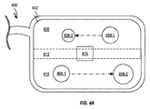
図4A−4Bは、第1の仮想コンテンツ404および第2の仮想コンテンツ406を表示する、ARデバイス400の透明ディスプレイ402を示す。図4Aは、仮想コンテンツ404および406が特定の時間周期にわたって透明ディスプレイ402を横断して移動する様子を示す、矢印を描写する。本移動の間、仮想コンテンツ404は、ARデバイス400からさらに離れるように進行し、仮想コンテンツ406は、ARデバイス400により近接して進行する。透明ディスプレイ402は、仮想コンテンツの見掛け深度を調節するための調整可能レンズを含むため、透明ディスプレイ402の上側領域408は、ARデバイス400からさらに離れるように移動する仮想コンテンツ404を表示するように光学的に構成されることができ、下側領域410は、ARデバイス400により近接して移動する仮想コンテンツ406を表示するように構成されることができる。遷移領域412は、調整可能レンズの形状が、異なる光学構成に適応し、上側および下側領域408および410の間の視覚的シームの出現を防止するように徐々に調節される領域の形態をとることができる。遷移領域412は、領域408および410の間の差異の量に応じて、より大きい、またはより小さくあり得る。実世界オブジェクト414が遷移領域412内に位置付けられるが、透明ディスプレイ402が、実世界オブジェクトの歪みを防止するように協働する2つの調整可能レンズを含むとき、遷移領域412であっても、実世界オブジェクト414の外観に殆どまたは全く影響を及ぼさないであろうことを理解されたい。この理由から、上側領域408および下側領域410のためのディスプレイ402の好適な面積を決定するように試行するARデバイス400のプロセッサは、仮想コンテンツを独立して移動させるための光学構成を変動する方法を決定するとき、仮想コンテンツに関する運動の経路のみを考慮する必要があるであろう。
4A-4B show the
図4Bは、仮想コンテンツ454が運動し、仮想コンテンツ456が定常のままである例示的実施形態を示す。そのような構成では、運動領域458は、透明ディスプレイ402の視認可能面積の大部分を占めることができる一方、定常領域460は、主として、仮想コンテンツ456に限定されるはるかに小さい面積を占めることができる。さらに、運動領域458は、ARデバイス400と仮想コンテンツ454との間の見掛け距離を改変することができる一方、定常領域460は、仮想コンテンツ456までの見掛け距離を維持することができる。本狭い定常領域460は、ユーザの頭部移動がありそうにないと見なされる場合、または透明ディスプレイ402内の仮想コンテンツの場所がユーザの頭部移動によって統御されない場合、さらにより便宜的であり得る。例えば、仮想コンテンツ456は、時刻、バッテリ充電、またはナビゲーション情報等のステータス情報の形態をとり得る。本タイプの情報は、これがまた、ユーザが相互作用しているどの他の仮想コンテンツであろうと、ともに移動する場合、注意を逸らし得る。また、再び、実世界コンテンツ464は、透明ディスプレイ402の調整可能レンズによって影響を受ける見掛け深度変化によって影響を受けないままであることに留意されたい。
FIG. 4B shows an exemplary embodiment in which the virtual content 454 is in motion and the
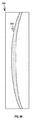
図5A−5Bは、調整可能レンズ502の側面図および調整可能レンズ502が異なる仮想コンテンツ位置に適応するように調節され得る様子を示す。図5Aは、調整可能レンズ502が形状において略長方形であり、長方形体積内にレンズ要素504を形成し得る様子を示す。レンズ要素504は、ARデバイスのユーザからの所望の距離に仮想コンテンツを確立するために、導波管から放出された光を再成形するように構成されることができる。調整可能レンズ502が液晶レンズの形態をとるとき、レンズ要素504は、調整可能レンズ502に印加されている電圧に応答して、形状をレンズ要素506に変化させることができる。レンズ要素506の増加された深度および曲率は、仮想コンテンツがレンズ要素504よりもARデバイスにより近接して見えるようにすることができる。このように、調整可能レンズは、ARデバイスから視認される仮想コンテンツまでの見掛け距離を変化させるように構成されることができる。
5A-5B show a side view of the
図5C−5Dは、調整可能レンズ502が仮想コンテンツによって表される複数の独立して移動するオブジェクトの運動に適応するように調節され得る様子を示す。特に、図5Cおよび5Dは、調整可能レンズ502が図4A−4Bに描写される仮想コンテンツ運動に適応するために移動する必要があるであろう様子を示すことができる。図5Cは、仮想コンテンツ404および406がARデバイスから同一の距離において開始される状況に対応し得る。図5Dは、調整可能レンズ502がレンズ要素508の形成からレンズ要素510の形成に遷移する様子を示す。上側領域512に対応するレンズ要素510の部分は、ARデバイスからさらに離れるように移動する仮想コンテンツ404の外観を与えるために、より薄い有効形状およびより小さい有効曲率を有することができる一方、下側領域514に対応するレンズ要素510の部分は、ARデバイスにより近接して移動する仮想コンテンツ406の外観を与えるために、より厚い有効形状およびより大きい有効曲率を有することができる。遷移領域516は、調整可能レンズ502を通した実世界のビューに影響を及ぼす可視線を生成することなく、レンズ要素510の有効厚さを平滑に変化させる勾配を含む。
FIG. 5C-5D shows how the
図6は、小型形状因子のARデバイスを使用して複数の深度において仮想コンテンツを表示するための方法を描写する、フローチャートを示す。602において、ARデバイスの深度センサが、ユーザと実世界オブジェクトとの間の距離を決定することによって、ARデバイスのユーザの視野内の実世界オブジェクトを特性評価する。604において、ARデバイスのプロセッサが、特性評価された実世界オブジェクトに対する第1の仮想コンテンツに関する場所または運動経路を決定するように構成される。606において、ARデバイスの第1の調整可能レンズの光学構成が、第1の仮想コンテンツの初期表示のために構成される。608において、ARデバイスの第2の調整可能レンズの光学構成が、第1の調整可能レンズが実世界オブジェクトのビューに悪影響を及ぼすことを防止するように構成される。これは、実世界オブジェクトに関して第1の調整可能レンズによって適用される光学効果の少なくとも一部を相殺する第2の調整可能レンズの光学構成によって遂行される。ある場合には、第2の調整可能レンズは、実世界オブジェクトの外観への第1の調整可能レンズの効果を相殺するために、第1の調整可能レンズに相補的であり得ることに留意されたい。いくつかの実施形態では、ある視覚強化が、第1の調整可能レンズによって行われる調節の一部を変化させないままにすることによって適用されることができる。いくつかの実施形態では、第2の仮想コンテンツの表示が所望される場合、ARデバイスは、第1および第2の仮想コンテンツがユーザから同一の距離にあるべきかどうかを確認するためにチェックするように構成されることができる。612において、ARデバイスは、第1および第2の仮想コンテンツの位置を追跡するために、調整可能レンズを調節し続けることによって、光学構成を維持することができる。 FIG. 6 shows a flowchart illustrating a method for displaying virtual content at multiple depths using a small Scherrer AR device. At 602, the depth sensor of the AR device characterizes the real-world object in the user's field of view of the AR device by determining the distance between the user and the real-world object. At 604, the processor of the AR device is configured to determine the location or motion path for the first virtual content for the characterized real-world object. At 606, the optical configuration of the first adjustable lens of the AR device is configured for the initial display of the first virtual content. At 608, the optical configuration of the second adjustable lens of the AR device is configured to prevent the first adjustable lens from adversely affecting the view of real-world objects. This is accomplished by the optical configuration of the second adjustable lens, which offsets at least some of the optical effects applied by the first adjustable lens with respect to real-world objects. Note that in some cases, the second adjustable lens may be complementary to the first adjustable lens to offset the effect of the first adjustable lens on the appearance of real-world objects. sea bream. In some embodiments, certain visual enhancements can be applied by leaving some of the adjustments made by the first adjustable lens unchanged. In some embodiments, if the display of the second virtual content is desired, the AR device checks to see if the first and second virtual content should be at the same distance from the user. Can be configured as At 612, the AR device can maintain the optical configuration by continuing to adjust the adjustable lens to track the position of the first and second virtual content.
614において、第1および第2の仮想コンテンツがユーザから異なる距離にあるとき、プロセッサは、調整可能レンズを使用して、ARデバイスディスプレイの異なる領域に異なる光学構成を適用するように構成されることができる。このように、ユーザは、ユーザから異なる距離に仮想コンテンツを提示されることができる。いくつかの実施形態では、第2の仮想コンテンツは、ユーザの注意が第1の仮想コンテンツに集中するように意図されるとき、意図的に焦点を外したままにされることができる。例えば、焦点は、いったん第2の仮想コンテンツとの相互作用がユーザによって所望される、またはARデバイスによって実行されているソフトウェアによって待ち行列に入れられると、第2の仮想コンテンツに遷移されることができる。いくつかの実施形態では、ユーザから異なる距離における仮想コンテンツの間の焦点遷移は、ユーザが特定の仮想オブジェクトに焦点を合わせているかどうかを決定するように構成される眼追跡センサによって待ち行列に入れられることができる。他の実施形態では、ユーザは、相互作用のために仮想コンテンツを手動で選択することができ、その点において、焦点が、選択された仮想オブジェクトとユーザとの間の距離を適切に描写するように調節され得る。結像ソフトウェアが、全ての仮想コンテンツがユーザから同一の距離にあるいかなる印象も回避するために、現在の深度平面の外側のARデバイスによって投影される任意の仮想コンテンツにぼけ効果を適用するために使用されることができる。 At 614, when the first and second virtual content are at different distances from the user, the processor is configured to use an adjustable lens to apply different optical configurations to different areas of the AR device display. Can be done. In this way, the user can present the virtual content at different distances from the user. In some embodiments, the second virtual content can be intentionally left out of focus when the user's attention is intended to focus on the first virtual content. For example, the focus may transition to the second virtual content once the interaction with the second virtual content is desired by the user or queued by the software running on the AR device. can. In some embodiments, focus transitions between virtual content at different distances from the user are queued by an eye tracking sensor configured to determine if the user is focused on a particular virtual object. Can be In other embodiments, the user can manually select virtual content for interaction, in which way the focus will adequately depict the distance between the selected virtual object and the user. Can be adjusted to. To apply the blur effect to any virtual content projected by an AR device outside the current depth plane, in order for the imaging software to avoid any impression that all virtual content is at the same distance from the user. Can be used.
図7A−7Bは、光をディスプレイデバイスからユーザの眼に指向するように構成される、種々の実施形態を示す。図7Aは、光プロジェクタ702と、プロジェクタ702によって放出された光706をユーザの眼708に向かって再指向するように構成される導波管704とを含む、ディスプレイデバイス700の上面図を示す。導波管706は、数千またはさらには数百万の場所から画像を放出するように構成されることができるが、図7Aは、それから5つの出力円錐710−1〜710−5が描写される、5つの例示的場所から放出されている光を示す。出力円錐710はそれぞれ、有効角度と称され得る、角度712を横断して拡散されている各場所から放出された光を表す。描写されるように、各出力円錐の限定されたサイズは、出力円錐710−1および710−5に沿って導波管704から出射する光がユーザの眼708に到着することを防止する。いくつかの実施形態では、角度712は、例えば、導波管706の材料屈折率等のディスプレイ技術のある特性によって、所望の閾値を下回って限定される。光照射野および導波管ベースのディスプレイデバイスに関する付加的詳細が、「HIGH RESOLUTION HIGH FIELD OF VIEW DISPLAY」と題された米国仮特許出願第62/539,934号に提供されている。
7A-7B show various embodiments configured to direct light from the display device to the user's eye. FIG. 7A shows a top view of the
図7Bは、ディスプレイデバイス700が、描写されるように、有効視野角712を角度716まで拡大するために、導波管704から出射する光706を異なる方向に連続的に偏移させるように構成される、光学操向デバイス714等の1つ以上の光学操向コンポーネントを組み込み得る様子を示す。このように、ユーザの眼708は、出力円錐710−1〜710−5を異なる方向に偏移させることによって生成されるより大きい有効角度716に起因して、より広い視野を視認することが可能である。描写されるように、拡大された有効角度716は、出力円錐710−1および710−5からの光の少なくとも一部がユーザの眼708に到着することを可能にする。いくつかの実施形態では、光学操向コンポーネント714は、複数の異なる光学構成をとることが可能な1つ以上の調整可能プリズム(例えば、再構成可能な位相プロファイルを有する液晶レンズ)の形態をとることができる。各光学構成は、出力円錐710の方向を異なる方向に偏移させるように構成されることができる。図7Bは、2つの異なる方向に操向されている光706のみを示すが、光706は、多くの他の異なる方向に操向され得ることを理解されたい。さらに、調整可能プリズムに加えて、他の光学要素も、光をユーザの眼に向かって再指向するように構成され得、例示的プリズム実施形態は、本開示の範囲の限定として解釈されるべきではないことを理解されたい。
FIG. 7B is configured such that the
他のそのような光学要素の実施例(例えば、時変格子)が、米国特許出願第14/555,585号にさらに詳細に説明されている。いくつかの実施例では、ポリマー分散液晶格子または他の調整可能格子が、光学操向コンポーネントとして実装され、TIR導波光の角度、光が導波管704の外部結合光学要素によって外部結合される角度、またはそれらの組み合わせを修正することによって、出力円錐710−1〜710−5を操向するために使用されてもよい。いくつかの実施形態では、1つ以上のメタ表面(例えば、メタマテリアルから作製される)が、光学操向コンポーネントとして実装されてもよい。本開示の種々の実施形態において光学操向コンポーネントとして使用され得るメタ表面およびメタマテリアルに関するさらなる情報が、米国特許公開第15/588,350号、米国特許公開第15/182,528号、および米国特許公開第15/182,511号に見出されることができる。したがって、光学操向コンポーネントは、離散数の異なる操向状態において動作するように切替可能または別様に制御可能であり得、例示的調整可能光学操向デバイスは、本開示の範囲の限定として解釈されるべきではないことを理解されたい。
Examples of other such optics (eg, time-varying lattices) are described in more detail in US Patent Application No. 14 / 555,585. In some embodiments, a polymer-dispersed liquid crystal lattice or other adjustable lattice is implemented as an optically steered component, the angle of the TIR waveguide light, the angle at which the light is externally coupled by the externally coupled optical elements of the
図8A−8Cは、好適なディスプレイデバイスによって生成され、ディスプレイデバイスの視野を拡大するために役立ち得る例示的走査パターンを示す。図8Aは、4つの異なる画像場所802、804、806、および808を含む、第1の走査パターンを示す。描写される画像場所はそれぞれ、特定の時点でディスプレイデバイスから放出される光の集合を表すことができる。いくつかの実施形態では、光は、場所802−808に番号順に送達されることができる。光学操向デバイスが、次いで、アクティブな画像場所に従って、ユーザの眼に向かって戻るように光を偏移させるために使用されることができる。例えば、画像場所808がアクティブであるとき、光学操向デバイスは、光をユーザの眼に向かって下向きに偏移させるように構成されることができる。ビデオ源がディスプレイデバイスによって提示されているとき、各画像場所に対応するビデオフレームの部分が、ビデオのフレーム毎に4つの場所のそれぞれにおいて連続的に表示されることができる。例えば、ビデオ源が、1/30秒のフレームレートを有するとき、ビデオフレームの対応する部分は、1/120秒にわたって各場所において表示されることができる。このように、拡大された視野が、フレームレート低減を伴わずに達成されることができる。このように、走査パターンによって生成される結果として生じる画像は、流動的なフレームレートを維持し、また、単一の定常画像場所を使用して可能であろうものよりも実質的に高い空間分解能を伴う合成画像を生成する。例えば、480ラインの垂直分解能のみを表示することが可能な画像プロジェクタは、前述の走査技法を使用して、480ラインを上回る分解能を伴う画像またはビデオ源を再現し得る。走査パターン、タイリング機能性、およびタイルドディスプレイ構成に関する付加的詳細が、米国特許出願第14/555,585号に提供されている。
8A-8C show exemplary scanning patterns produced by a suitable display device that can help expand the field of view of the display device. FIG. 8A shows a first scan pattern that includes four
図8Aはまた、図8Aに示されるハッシュ領域によって示されるように、いくつかの実施形態において、隣接する画像場所の部分が重複し得る様子を示す。これは、重複する画像場所内のコンテンツをもたらす。重複は、ディスプレイデバイスによって生成される合成画像のある側面をさらに改良するために使用されることができる。例えば、中心領域810内の分解能の増加が、1つ以上の超分解能技法を適用することによって達成されることができる。特に、重複する各画像フレームの部分は、サブサンプリングされ、わずかにオフセットされ、ピクセルが相互にスタックされる代わりに、ピクセル密度の増加を可能にすることができる。これは、重複する領域を伴うディスプレイの部分において超分解能効果を生じる。例えば、ディスプレイプロセッサが4K分解能画像(すなわち、2,160ラインの垂直分解能)を生成することが可能である実施形態では、4K分解能画像は、走査パターンの重複領域内にピクセルを分配することによって、通常、実質的により低い分解能を生成することのみが可能な画像源を使用して超分解能効果を達成するために使用され得る。さらに、高フレームレートビデオファイルが表示されているとき、各連続的に表示されるフレームは、ビデオの異なるフレームと関連付けられることができる。例えば、120フレーム/秒ビデオ源を再生するとき、中心領域810内のディスプレイの部分は、全120フレーム/秒フレームレートを享受し得る一方、非重複領域は、30フレーム/秒のレートにおいてのみ更新されるであろう。中心領域810の近傍の重複領域は、特定の領域内の重複場所の数に応じて、60または90フレーム/秒のレートにおいてリフレッシュされ得る。
FIG. 8A also shows how parts of adjacent image locations can overlap in some embodiments, as shown by the hash region shown in FIG. 8A. This results in content within duplicate image locations. Duplication can be used to further improve certain aspects of the composite image produced by the display device. For example, an increase in resolution within the
図8Bは、大きい中心領域810を伴う第2の走査パターンを示す。本第2の走査パターンは、画像全体の9分の1が画像場所802−808のそれぞれによって重複されることをもたらす。このように、中心領域810内の分解能またはフレームレートは、非重複領域におけるものを実質的に上回ることができる。描写される走査パターンは、最大4倍の分解能またはフレームレート増加を達成することができ、これは、概して、重複するフレームの数に対応する。本タイプの走査パターンは、着目コンテンツがディスプレイの中心領域内に位置するときに特に有益であり得る。いくつかの実施形態では、走査パターンは、より少ない仮想コンテンツがディスプレイの周辺領域内に提示されている状況において、増加する量の重複を生成するために変更されることができる。
FIG. 8B shows a second scan pattern with a large
図8Cは、画像場所802−808のそれぞれに位置付けられる画像が、描写されるように卓上ランプの形態をとる合成画像812を協働的に生成する様子を示す。画像場所802−808のうちの任意の単一のものよりも大きい合成画像812を生成することに加えて、画像場所802−808のそれぞれにおける画像の連続的表示は、ディスプレイの光学性質が、所与の走査の間に現在アクティブである画像場所802−808に従って変更されることを可能にする。例えば、画像が画像場所804において表示されているとき、光学性質は、ランプ812の基部を表す光をユーザの眼に向かって偏移させるように調節され得る。いくつかの実施形態では、走査パターンの場所は、ランプ812等の仮想画像を走査パターンの中心領域内に設置するディスプレイの場所に位置付けられることができる。これは、画像の中心および/または重要な特徴が、より多数の画像場所において表示されることを可能にする。
FIG. 8C shows how the images located at each of the image locations 802-808 collaboratively generate a
図9A−9Cは、図8Aに描写される第1の走査パターンが表示領域900内の周辺に偏移され得る様子を示す。図9Aは、時間t0における表示領域900の左上隅における第1の走査パターンを示す。図9Bは、時間t1における表示領域900の右上隅に向かって偏移された第1の走査パターンを示す。いくつかの実施形態では、ディスプレイデバイスは、眼注視トラッカを含むことができる。眼注視トラッカによって提供されるセンサデータは、走査パターンをユーザの現在の焦点に対応する表示領域900内の場所に偏移させるために利用されることができる。いくつかの実施形態では、本センサデータは、ユーザの中心視(すなわち、最も高い視力を伴うユーザの視覚のその部分)を網羅する場所に中心領域810を保つことに役立つことができる。このように走査パターンを連続的に調節することによって、ユーザの没入感が、改良されることができる。本方法は、顕著なコンテンツが表示領域900の中心部分から離れるように頻繁に偏移するときに特に効果的であり得る。中心視追跡を実施し、中心視される仮想コンテンツをレンダリングし、中心視される仮想コンテンツをユーザに表示するための例示的システムおよび技法が、「HIGH RESOLUTION HIGH FIELD OF VIEW DISPLAY」と題された米国仮特許出願第62/539,934号にさらに詳細に説明されている。
9A-9C show how the first scanning pattern depicted in FIG. 8A can be displaced to the periphery within the
図9Cは、表示領域900の下側部分に向かって再び偏移された第1の走査パターンを示す。図9A−9Cはまた、画像場所802−808が第1の走査パターンの位置に従って、および/またはユーザに提示されているコンテンツをより良好に表すために変化し得る様子を示す。例えば、それを横断して第1の走査パターンが延在する面積が、標準走査パターンサイズよりもはるかに小さい仮想画像をより良好に表すために、縮小され得る。いくつかの実施形態では、走査パターンを変更することは、仮想コンテンツの特定の表現のために走査パターンの重複する領域を最適化するために役立つことができる。
FIG. 9C shows a first scan pattern that has been re-shifted towards the lower portion of the
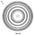
図10A−10Eは、光学操向デバイス714と類似する光学操向デバイスに関する種々の位相プロファイルを示す。特に、図10Aは、光を垂直に偏移させるための第1の光学構成1004における例示的光学操向デバイス1002の正面図を示す。図10Bは、区分線A−Aによる光学操向デバイス1002の断面側面図を示す。光学操向デバイス1002は、液晶レンズに印加される電圧の量に従って、その位相プロファイルを変化させることが可能な液晶レンズの形態をとることができる。より具体的には、光学操向デバイス1002は、それへの電圧の印加に応答して、電場を生産することが可能な構造を伴う2つの伝導層を含んでもよい。このように、光学操向デバイス1002は、複数の異なる光学構成の間で偏移することができる。第1の光学構成1004は、光学操向デバイス1002内に複数の屈折率を伴う位相プロファイルを有することができる。いくつかの実施例では、光学操向デバイス1002の局所的屈折率は、プリズム機能または別の所望の光学機能を満たすように調整されてもよい。これらの実施例のうちの少なくともいくつかでは、光学操向デバイス1002は、比較的に大きい位相勾配(例えば、約πrad/μm)を呈し得る。特に、屈折率は、描写されるように、鋸歯プロファイルに従って変動することができ、歯はそれぞれ、光1006の一部を受け取り、光1008を異なる方向に放出するように構成されることができる。歯のサイズおよび/または間隔は、光学操向デバイス1002を通過する光の角度の変化を低減または増加させるように調節されることができる。例えば、各楔の角度は、楔のパターンがディスプレイの中心領域に接近するにつれて徐々に低減され得る。本第1の光学構成1004は、ディスプレイの下側中心領域に位置する走査パターンのフレームを偏移させるために使用され得る。
10A-10E show various phase profiles for an optical steering device similar to the
図10Cは、第2の光学構成1010における光学操向デバイス1002の正面図を示す。図10Dは、区分線B−Bによる、第2の光学構成における光学操向デバイス1002の断面上面図を示す。第2の光学構成では、光学操向デバイス1002は、光1012を側方に偏移させるように構成される。描写されるように、光学操向デバイス1002は、光1012を受け取り、側方に偏移された光1014を出力する。第1および第2の描写される光学構成の両方が、光の方向を偏移させるが、それらは、垂直または水平のみでそのように行う。いくつかの実施形態では、2つの光学操向デバイスが、受け取られた光を垂直および水平の両方で偏移させるために、相互に積み重ねて層化され得ることを理解されたい。
FIG. 10C shows a front view of the
図10Eは、一連の歯形隆起を光学操向デバイス1002を横断して対角線に配向することによって、光が単一の光学操向デバイス1002によって垂直および水平の両方で偏移され得る様子を示す。図10Eはまた、描写される対角線構成が、別様に1次元光学操向デバイス1016および1018を利用するであろう光の偏移を遂行し得る様子を示す。描写される構成は、光が表示領域の右下領域を通して導波管から出射する走査パターンのフレームの間に光学操向デバイス1002によってとられ得る。複数の光学構成が描写されたが、光学操向デバイス1002は、描写されていない多くの他の構成において再配列され得ることに留意されたい。
FIG. 10E shows how light can be deflected both vertically and horizontally by a single
図11A−11Bは、光学操向デバイスが、垂直および水平の両方で着信する光を偏移させるために相互にスタックされるレンズを含み得る様子を示す。図11Aは、水平偏移レンズ1102と、垂直偏移レンズ1104とを含む、光学操向デバイス1100の位相偏移の斜視図を示す。2つのレンズは、レンズに入射する光を再指向するために、相互にスタックされることができる。本光学構成は、着信する光が垂直および水平の両方で偏移されることを可能にする。図11Bは、複数のレンズのアレイを使用することによって達成される低減された厚さを有する光学操向デバイス1120を示す。いくつかの実施形態では、液晶レンズが、図11Bに描写されるように、複数の水平偏移レンズ1102および垂直偏移レンズ1104と同等である光学構成を形成するために使用されることができる。
11A-11B show how an optical steering device can include lenses that are stacked on top of each other to shift incoming light both vertically and horizontally. FIG. 11A shows a perspective view of the phase shift of the
図11C−11Dは、それぞれ、フレネルレンズ構成を有する液晶レンズ1140の断面側面図および上面図を示す。フレネルレンズ構成は、選択された仮想コンテンツを拡大または縮小するために、光学操向デバイスの形態をとることができる。特に、図11Cは、液晶レンズ1140を通過する光の倍率を変更すること、およびそれを側方に偏移させることの両方を行うように構成される、フレネルレンズ構成を描写する。本タイプの構成は、本明細書に説明される光学操向デバイスのうちのいずれかに組み込まれ得る。いくつかの実施形態では、ユーザは、画面の特定の領域の拡大を要求し得る。応答して、光学操向デバイスは、ユーザによって視認されている特定の画像ストリームを生成する光を変化させる、または更新する必要性なくコンテンツを拡大するために、特定の領域にわたってフレネルレンズ構成を形成するように構成され得る。
11C-11D show a cross-sectional side view and a top view of a
図12A−12Bは、光学操向デバイスが拡張現実ディスプレイデバイスに組み込まれ得る異なる方法を示す。いくつかの実施形態では、光学操向デバイスは、それに入射する光の方向、遠近感、および/または倍率を変更するために、屈折率を選択的に変更することが可能な液晶レンズの形態をとることができる。図12Aは、ディスプレイデバイス1200の断面上面図を示す。光学操向デバイス1202および1204が、ディスプレイデバイス1200の導波管1206の両側上に位置付けられる。導波管1206は、異なる色の光をディスプレイデバイス1200のユーザの眼1208に搬送するための1つ以上の離散経路を含むことができる。光学操向デバイス1202および1204は、実世界オブジェクトから反射された光1210が、両方の光学操向デバイスを通過し、実質的に歪曲されない様式で眼1208に到達することを可能にする、実質的に相補的な構成を有することができる。導波管1206によって搬送される光1212が、次いで、光1210を有害に歪曲させることなく、1つ以上の走査パターンに従ってビーム操向を受けることによって、仮想コンテンツを可視化するように構成されることができる。前述で説明される走査パターンおよび連続的ビーム操向は、ディスプレイデバイス1200の有効視野を増加させる。図12Bは、ディスプレイデバイス1220と、光学操向デバイス1202および1204が、動的焦点偏移および視野拡大の両方が光1212に適用され得るように、可変焦点レンズ1209を組み込まれ得る様子とを示す。
12A-12B show different ways in which an optical steering device can be incorporated into an augmented reality display device. In some embodiments, the optical steering device comprises the form of a liquid crystal lens in which the refractive index can be selectively changed in order to change the direction, perspective, and / or magnification of the light incident on it. Can be taken. FIG. 12A shows a cross-sectional top view of the
図12C−12Fは、複数の画像ストリームを受信するように構成されるディスプレイデバイスを示す。図12Cは、導波管1206および導波管1244の両方を含むディスプレイデバイス1240の上面断面図を示す。導波管1244は、広い視野、低分解能の画像のストリームを形成する、光1246を搬送するように構成されることができる。描写されるように、光1246は、眼1208に到達することに先立って、いかなる走査パターンも受けない。導波管1206は、狭い視野、高分解能の画像のストリームを形成する、光1212を搬送するように構成されることができる。導波管1244に入射する光1212は、センサがユーザの眼が焦点を合わせていることを示す領域内でディスプレイデバイス1240から出射するように構成されることができる。このように、狭い視野、高分解能の画像のストリームの動的中心視が、達成され、ユーザがディスプレイデバイス1240の全てが高分解能画像を放出しているという印象を与えられることをもたらすことができる。光1212は、ディスプレイデバイスの表面を横断して投影されることができ、光学操向デバイス1202は、ユーザのための有効視野を増加させる走査パターンにおいて光1212を動的に操向することができる。走査パターンに起因する光1212によって生成される画像のストリームの結果として生じる拡大は、ユーザがディスプレイデバイスの表示領域の縁の近傍のコンテンツに焦点を合わせているときであっても、高分解能を判別することが可能なユーザの視野の領域が光1212によって完全に被覆されることに役立つことができる。このように、ディスプレイ1240は、ユーザの視野全体を横断して高分解能画像を表示する必要がないため、ハードウェア費用および処理能力の有意な節約が、達成されることができる。
12C-12F show a display device configured to receive multiple image streams. FIG. 12C shows a top sectional view of the
図12Dは、ディスプレイデバイス1240の正面図および光1212および1246がユーザの眼1208の網膜上に投影される際にユーザによって知覚されるような画像の表現を示す。図12Dは、光を放出することが可能な導波管1244の一部および光1212を放出する導波管1244の領域を示す。光1212は、走査パターンにおいて偏移する狭い視野の画像ストリームを生産するように描写される。光1246は、定常のままである広い視野を提供する。いくつかの実施形態では、それを横断して光1246が延在する面積は、それを横断して光が光学操向デバイスを伴わずに視認可能である最大視認可能面積を表す。描写されるように、光1212の一部は、眼1208に向かって光1212を偏移させる、光学操向デバイス1202から利益を享受する光1212のため、光1246によって被覆される領域の外側に延在することができる。
FIG. 12D shows a front view of the
図12Eは、光学操向デバイス1262および1264を図12Cに描写される構成に追加する、ディスプレイデバイス1260を示す。本実施形態では、狭い視野、高分解能の画像を生成する光1212は、導波管1244を通して指向されることができ、広い視野、低分解能の画像を生成する光1246は、導波管1206を通して指向されることができる。光学操向デバイス1262は、光1212を独立して操向するように構成される。光学操向デバイス1264は、光1210および光1246が光学操向デバイス1262の操向によって歪曲されることを防止するように構成される。光学操向デバイス1264は、光学操向デバイス1262の位相プロファイルに実質的に相補的な位相プロファイルを維持することができる。このように、光1246および1212によって生成される仮想コンテンツは、拡大された視野を横断して延在し、それによって、ディスプレイデバイス1260のユーザのための没入体験をさらに改良することができる。いくつかの実施形態では、光学操向デバイス1202および1264の機能性は、所望の走査パターンにおいて光1246を偏移させること、および光学操向デバイス1262によって生成されているいかなる干渉もプリエンプティブに補償することの両方を行う位相プロファイルをとることが可能な単一の光学操向デバイスに組み合わせられ得ることに留意されたい。
FIG. 12E shows a
いくつかの実施形態では、ディスプレイデバイス1260の1つ以上のプロジェクタによって生成される光1246および1212は、実質的に同一の空間分解能において画像のストリームを表示するように構成されることができる。光学操向デバイス1202および1262は、次いで、ディスプレイデバイス1260の有効視野を最大限にするために、独立して作用し、走査パターンを光1212および1246に適用するように構成されることができる。導波管1206および1244の間の分離は、ユーザと光1212および1246によって生成される仮想コンテンツとの間に異なる見掛け距離を生成するように構成されることができる。このように、深度知覚距離が、図12Bに示されるように、可変焦点レンズのセットを伴わずに調節されることができる。いくつかの実施形態では、異なる距離における導波管および可変焦点レンズが、眼1208から複数の異なる見掛け距離において仮想コンテンツを並行して示すために組み合わせて使用され得ることに留意されたい。可変焦点レンズは、次いで、前述で説明されるように、眼1208と仮想コンテンツとの間の見掛け距離を変化させるために使用され得る。
In some embodiments, the
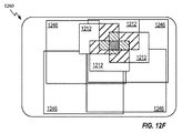
図12Fは、ディスプレイデバイス1260の正面図および光1212および1246がユーザの眼1208の網膜上に投影される際にユーザによって知覚されるような画像の表現を示す。特に、図12Fは、光1212が第1の走査パターンにおいて偏移する狭い視野を有し得る様子と、光1246が第1の走査パターンとは異なる第2の走査パターンにおいて偏移する広い視野を提供し得る様子とを示す。いくつかの実施形態では、走査パターンは、同一のサイズおよび/または分解能を有することができる。そのような構成は、ユーザと仮想コンテンツとの間の見掛け距離を変動する利益を有し得る。
FIG. 12F shows a front view of the
説明される実施形態の種々の側面、実施形態、実装、または特徴は、別個に、または任意の組み合わせにおいて使用されることができる。説明される実施形態の種々の側面は、ソフトウェア、ハードウェア、またはハードウェアおよびソフトウェアの組み合わせによって実装されることができる。説明される実施形態はまた、製造動作を制御するためのコンピュータ可読媒体上のコンピュータ可読コードとして、または製造ラインを制御するためのコンピュータ可読媒体上のコンピュータ可読コードとして、具現化されることができる。コンピュータ可読媒体は、その後、コンピュータシステムによって読み取られ得るデータを記憶し得る、任意のデータ記憶デバイスである。コンピュータ可読媒体の実施例は、読取専用メモリ、ランダムアクセスメモリ、CD−ROM、HDD、DVD、磁気テープ、および光学データ記憶デバイスを含む。コンピュータ可読媒体はまた、コンピュータ可読コードが分散方式において記憶および実行されるように、ネットワーク結合されたコンピュータシステムを経由して分散されることができる。 The various aspects, embodiments, implementations, or features of the embodiments described can be used separately or in any combination. The various aspects of the embodiments described can be implemented by software, hardware, or a combination of hardware and software. The embodiments described can also be embodied as computer-readable code on a computer-readable medium for controlling manufacturing operations or as computer-readable code on a computer-readable medium for controlling a manufacturing line. .. A computer-readable medium is any data storage device that can subsequently store data that can be read by a computer system. Examples of computer-readable media include read-only memory, random access memory, CD-ROMs, HDDs, DVDs, magnetic tapes, and optical data storage devices. Computer-readable media can also be distributed via networked computer systems so that computer-readable code is stored and executed in a distributed manner.
前述の説明は、解説の目的のために、説明される実施形態の徹底的な理解を提供するために具体的名称を使用した。しかしながら、具体的詳細は、説明される実施形態を実践するために要求されないことが当業者に明白となるであろう。したがって、具体的実施形態の前述の説明は、例証および説明の目的のために提示される。それらは、包括的であること、または説明される実施形態を開示される精密な形態に限定することを意図していない。多くの修正および変形例が、上記の教示に照らして、可能性として考えられることが当業者に明白となるであろう。 The above description has used specific names to provide a thorough understanding of the embodiments described, for purposes of explanation. However, it will be apparent to those skilled in the art that no specific details will be required to practice the embodiments described. Therefore, the aforementioned description of the specific embodiments is presented for purposes of illustration and description. They are not intended to be inclusive or to limit the embodiments described to the disclosed precise forms. It will be apparent to those skilled in the art that many modifications and variations are considered possible in the light of the above teachings.
Claims (8)
導波管と、
前記導波管のユーザ向き側上に位置付けられ、かつ前記導波管に平行である、第1の光学操向コンポーネントと、
前記導波管の世界向き側上に位置付けられ、かつ前記導波管に平行である、第2の光学操向コンポーネントと、
仮想コンテンツを表す光を前記導波管中へと放出するように構成される光源と
を備え、
前記導波管は、前記光源から放出された前記光を前記第1の光学操向コンポーネントを通して前記ウェアラブルディスプレイデバイスのユーザに向かって回折するように構成される回折光学系を含み、前記光源は、前記光が前記第1の光学操向コンポーネントの異なる周辺領域を通して放出されることをもたらす走査パターンに従って、前記光を放出するように構成され、
前記第1の光学操向コンポーネントは、前記第1の光学操向コンポーネントの前記異なる周辺領域のうちの1つ以上において、前記光源から受け取られる前記光の少なくとも一部を、前記異なる周辺領域間の中心領域に向かって偏移させるように構成され、
前記中心領域の場所は、前記ウェアラブルディスプレイデバイスの動作中に調節することができる、ウェアラブルディスプレイデバイス。 A wearable display device
Waveguide and
A first optical steering component located on the user-facing side of the waveguide and parallel to the waveguide.
A second optical steering component located on the world facing side of the waveguide and parallel to the waveguide.
A light source configured to emit light representing virtual content into the waveguide.
The waveguide includes a diffractive optical system configured to diffract the light emitted from the light source through the first optically steered component towards the user of the wearable display device. The light is configured to emit the light according to a scanning pattern that results in the light being emitted through different peripheral regions of the first optically steered component.
In one or more of the different peripheral regions of the first optical steering component, the first optical steering component receives at least a portion of the light received from the light source between the different peripheral regions. Configured to shift towards the central region ,
The location of the central region of the wearable display device can be adjusted during operation of the wearable display device.
前記導波管の前記世界向き側上に位置付けられる第2のレンズと
をさらに備える、請求項1に記載のウェアラブルディスプレイデバイス。 A first lens positioned on the user-facing side of the waveguide,
The wearable display device according to claim 1, further comprising a second lens located on the world facing side of the waveguide.
Priority Applications (1)
| Application Number | Priority Date | Filing Date | Title |
|---|---|---|---|
| JP2021164535A JP2022008883A (en) | 2017-03-22 | 2021-10-06 | Dynamic field-of-view variable focus display system |
Applications Claiming Priority (3)
| Application Number | Priority Date | Filing Date | Title |
|---|---|---|---|
| US201762475081P | 2017-03-22 | 2017-03-22 | |
| US62/475,081 | 2017-03-22 | ||
| PCT/US2018/023847 WO2018175780A1 (en) | 2017-03-22 | 2018-03-22 | Dynamic field of view variable focus display system |
Related Child Applications (1)
| Application Number | Title | Priority Date | Filing Date |
|---|---|---|---|
| JP2021164535A Division JP2022008883A (en) | 2017-03-22 | 2021-10-06 | Dynamic field-of-view variable focus display system |
Publications (3)
| Publication Number | Publication Date |
|---|---|
| JP2020514826A JP2020514826A (en) | 2020-05-21 |
| JP2020514826A5 JP2020514826A5 (en) | 2021-04-30 |
| JP6957635B2 true JP6957635B2 (en) | 2021-11-02 |
Family
ID=63582446
Family Applications (2)
| Application Number | Title | Priority Date | Filing Date |
|---|---|---|---|
| JP2019551537A Active JP6957635B2 (en) | 2017-03-22 | 2018-03-22 | Variable focus display system with dynamic field of view |
| JP2021164535A Pending JP2022008883A (en) | 2017-03-22 | 2021-10-06 | Dynamic field-of-view variable focus display system |
Family Applications After (1)
| Application Number | Title | Priority Date | Filing Date |
|---|---|---|---|
| JP2021164535A Pending JP2022008883A (en) | 2017-03-22 | 2021-10-06 | Dynamic field-of-view variable focus display system |
Country Status (9)
| Country | Link |
|---|---|
| US (2) | US10859812B2 (en) |
| EP (1) | EP3602583A4 (en) |
| JP (2) | JP6957635B2 (en) |
| KR (2) | KR102438618B1 (en) |
| CN (2) | CN110447082B (en) |
| AU (2) | AU2018240367B2 (en) |
| CA (1) | CA3056924A1 (en) |
| IL (2) | IL269103B1 (en) |
| WO (1) | WO2018175780A1 (en) |
Families Citing this family (39)
| Publication number | Priority date | Publication date | Assignee | Title |
|---|---|---|---|---|
| WO2020086692A1 (en) * | 2018-10-23 | 2020-04-30 | Exciting Technology LLC | System, method and apparatus for non-mechanical optical and photonic beam steering |
| WO2021119165A1 (en) * | 2019-12-09 | 2021-06-17 | Exciting Technology LLC | System, method, and apparatus to steer an electromagnetic beam utilizing staged steering |
| US11835838B2 (en) | 2017-10-27 | 2023-12-05 | Exciting Technology LLC | System, method and apparatus for non-mechanical optical and photonic beam steering |
| US11835841B2 (en) | 2017-10-27 | 2023-12-05 | Exciting Technology LLC | System, method and apparatus for non-mechanical optical and photonic beam steering |
| US10845671B2 (en) | 2017-10-27 | 2020-11-24 | Exciting Technology, Llc | System, method and apparatus for non-mechanical optical and photonic beam steering |
| CN107861247B (en) * | 2017-12-22 | 2020-08-25 | 联想(北京)有限公司 | Optical component and augmented reality device |
| US10422989B2 (en) * | 2018-02-06 | 2019-09-24 | Microsoft Technology Licensing, Llc | Optical systems including a single actuator and multiple fluid-filled optical lenses for near-eye-display devices |
| US11245065B1 (en) | 2018-03-22 | 2022-02-08 | Facebook Technologies, Llc | Electroactive polymer devices, systems, and methods |
| US10962791B1 (en) | 2018-03-22 | 2021-03-30 | Facebook Technologies, Llc | Apparatuses, systems, and methods for fabricating ultra-thin adjustable lenses |
| US10690921B1 (en) * | 2018-03-26 | 2020-06-23 | Facebook Technologies, Llc | Apparatuses, systems, and methods for coordinated lens adjustments |
| US10914871B2 (en) | 2018-03-29 | 2021-02-09 | Facebook Technologies, Llc | Optical lens assemblies and related methods |
| US10359845B1 (en) * | 2018-05-01 | 2019-07-23 | Facebook Technologies, Llc | Display assembly using dynamic liquid crystal array |
| US10747309B2 (en) * | 2018-05-10 | 2020-08-18 | Microsoft Technology Licensing, Llc | Reconfigurable optics for switching between near-to-eye display modes |
| US10607353B2 (en) * | 2018-08-30 | 2020-03-31 | Facebook Technologies, Llc | Structured light depth sensing |
| US11227060B1 (en) | 2018-09-12 | 2022-01-18 | Massachusetts Mutual Life Insurance Company | Systems and methods for secure display of data on computing devices |
| US10893043B1 (en) * | 2018-09-12 | 2021-01-12 | Massachusetts Mutual Life Insurance Company | Systems and methods for secure display of data on computing devices |
| US11042649B1 (en) | 2018-09-12 | 2021-06-22 | Massachusetts Mutual Life Insurance Company | Systems and methods for secure display of data on computing devices |
| US20200333680A1 (en) | 2018-10-23 | 2020-10-22 | Exciting Technology, Llc | System, method and apparatus for non-mechanical optical and photonic beam steering |
| US11015830B2 (en) * | 2018-11-19 | 2021-05-25 | Johnson Controls Technology Company | Device using projector for display |
| US11022835B2 (en) * | 2018-12-15 | 2021-06-01 | Facebook Technologies, Llc | Optical system using segmented phase profile liquid crystal lenses |
| KR20200075533A (en) * | 2018-12-18 | 2020-06-26 | 삼성전자주식회사 | Apparatus and method for displaying image and computer program thereof |
| US11256331B1 (en) | 2019-01-10 | 2022-02-22 | Facebook Technologies, Llc | Apparatuses, systems, and methods including haptic and touch sensing electroactive device arrays |
| JP2022517207A (en) | 2019-01-11 | 2022-03-07 | マジック リープ, インコーポレイテッド | Time-multiplexed display of virtual content at various depths |
| US11467370B2 (en) | 2019-05-27 | 2022-10-11 | Samsung Electronics Co., Ltd. | Augmented reality device for adjusting focus region according to direction of user's view and operating method of the same |
| WO2021049831A1 (en) * | 2019-09-09 | 2021-03-18 | 삼성전자 주식회사 | Display device and system comprising same |
| KR20210035555A (en) | 2019-09-24 | 2021-04-01 | 삼성전자주식회사 | Augmented reality device and wearable device including the same |
| US20220394234A1 (en) * | 2019-11-08 | 2022-12-08 | Evolution Optiks Limited | System and method for implementing a viewer-specific image perception adjustment within a defined view zone, and vision correction system and method using same |
| US11822205B2 (en) | 2020-04-17 | 2023-11-21 | Exciting Technology LLC | System, method, and apparatus for high precision light beam steering using rotating lens elements |
| WO2021246777A1 (en) * | 2020-06-03 | 2021-12-09 | Samsung Electronics Co., Ltd. | Device and method for displaying augmented reality |
| KR102223621B1 (en) * | 2020-07-01 | 2021-03-05 | 부경대학교 산학협력단 | Augmented reality glasses with auto coregistration of invisible field on visible reality |
| CN112147786B (en) * | 2020-10-28 | 2024-04-12 | 南京爱奇艺智能科技有限公司 | Augmented reality display system |
| US11809622B2 (en) | 2020-12-21 | 2023-11-07 | Samsung Electronics Co., Ltd. | Electronic device and method for eye-tracking of user and providing augmented reality service thereof |
| KR20220089023A (en) * | 2020-12-21 | 2022-06-28 | 삼성전자주식회사 | Electronic device and method for eye-tracking of user and providing augmented reality service thereof |
| US11928257B2 (en) * | 2021-02-17 | 2024-03-12 | Samsung Electronics Co., Ltd. | Method and electronic device for tracking eye |
| CN117836695A (en) * | 2021-08-26 | 2024-04-05 | 谷歌有限责任公司 | Variable world blur for occlusion and contrast enhancement via tunable lens elements |
| WO2023030505A1 (en) * | 2021-09-03 | 2023-03-09 | University Of Central Florida Research Foundation, Inc. | An optical display system and an electronic device |
| CN113960800B (en) * | 2021-11-08 | 2023-09-29 | 歌尔光学科技有限公司 | Augmented reality device, diopter adjustment method thereof, and storage medium |
| CN114089835B (en) * | 2022-01-18 | 2022-04-26 | 湖北工业大学 | Mixed reality interactive guidance and identification system and method based on self-adaptive visual difference |
| WO2023200920A1 (en) * | 2022-04-13 | 2023-10-19 | Meta Platforms Technologies, Llc | Optical assembly for a head-mount display (hmd) device |
Family Cites Families (55)
| Publication number | Priority date | Publication date | Assignee | Title |
|---|---|---|---|---|
| US5309272A (en) | 1992-12-11 | 1994-05-03 | Xerox Corporation | Dual pass binary diffractive optical element scanner |
| US5694230A (en) | 1995-06-07 | 1997-12-02 | Digital Optics Corp. | Diffractive optical elements as combiners |
| CN1049288C (en) * | 1995-11-03 | 2000-02-09 | 邮电部武汉邮电学院研究院 | Manufacture method for single mode pigtail collimator of self-focusing lens type tunable optical filter |
| WO1998021612A1 (en) | 1996-11-12 | 1998-05-22 | Planop - Planar Optics Ltd | Optical system for alternative or simultaneous direction of light originating from two scenes to the eye of a viewer |
| JP2000298293A (en) * | 1999-04-15 | 2000-10-24 | Mr System Kenkyusho:Kk | Optical modulating device and three-dimensional image reproducing device using the same |
| US7023594B2 (en) * | 2000-06-23 | 2006-04-04 | E-Vision, Llc | Electro-optic lens with integrated components |
| JP2002214545A (en) * | 2001-01-18 | 2002-07-31 | Olympus Optical Co Ltd | Optical device |
| US7110180B2 (en) | 2002-10-09 | 2006-09-19 | Ricoh Company, Ltd. | Diffraction grating, method of fabricating diffraction optical element, optical pickup device, and optical disk drive |
| US7145722B2 (en) | 2003-04-24 | 2006-12-05 | Banpil Photonics, Inc. | Optical filter and method of manufacturing thereof |
| JP3912603B2 (en) * | 2003-09-05 | 2007-05-09 | ソニー株式会社 | Optical waveguide device |
| US7206107B2 (en) | 2004-12-13 | 2007-04-17 | Nokia Corporation | Method and system for beam expansion in a display device |
| US8885139B2 (en) * | 2005-01-21 | 2014-11-11 | Johnson & Johnson Vision Care | Adaptive electro-active lens with variable focal length |
| EP1932051A1 (en) | 2005-09-14 | 2008-06-18 | Mirage Innovations Ltd. | Diffraction grating with a spatially varying duty-cycle |
| US7817176B2 (en) | 2005-12-26 | 2010-10-19 | Ricoh Company, Ltd. | Light source device, optical scanning device, and image forming apparatus |
| EP1932492B1 (en) * | 2006-12-13 | 2011-09-14 | Akkolens International B.V. | Accommodating intraocular lens with variable correction |
| US20110075257A1 (en) | 2009-09-14 | 2011-03-31 | The Arizona Board Of Regents On Behalf Of The University Of Arizona | 3-Dimensional electro-optical see-through displays |
| US8233204B1 (en) * | 2009-09-30 | 2012-07-31 | Rockwell Collins, Inc. | Optical displays |
| US8248178B2 (en) | 2009-12-03 | 2012-08-21 | The Aerospace Corporation | High power waveguide polarizer with broad bandwidth and low loss, and methods of making and using same |
| US8467643B2 (en) | 2010-08-13 | 2013-06-18 | Toyota Motor Engineering & Mfg. North America, Inc. | Optical device using double-groove grating |
| US20120057235A1 (en) | 2010-09-03 | 2012-03-08 | Massachusetts Institute Of Technology | Method for Antireflection in Binary and Multi-Level Diffractive Elements |
| US9406166B2 (en) * | 2010-11-08 | 2016-08-02 | Seereal Technologies S.A. | Display device, in particular a head-mounted display, based on temporal and spatial multiplexing of hologram tiles |
| US8988463B2 (en) * | 2010-12-08 | 2015-03-24 | Microsoft Technology Licensing, Llc | Sympathetic optic adaptation for see-through display |
| US9323325B2 (en) * | 2011-08-30 | 2016-04-26 | Microsoft Technology Licensing, Llc | Enhancing an object of interest in a see-through, mixed reality display device |
| US20130300634A1 (en) * | 2012-05-09 | 2013-11-14 | Nokia Corporation | Method and apparatus for determining representations of displayed information based on focus distance |
| WO2013188464A1 (en) * | 2012-06-11 | 2013-12-19 | Magic Leap, Inc. | Multiple depth plane three-dimensional display using a wave guide reflector array projector |
| US9645394B2 (en) * | 2012-06-25 | 2017-05-09 | Microsoft Technology Licensing, Llc | Configured virtual environments |
| EP2893388B1 (en) * | 2012-09-03 | 2016-08-03 | SensoMotoric Instruments Gesellschaft für innovative Sensorik mbH | Head mounted system and method to compute and render a stream of digital images using a head mounted system |
| KR20150054967A (en) * | 2012-09-11 | 2015-05-20 | 매직 립, 인코포레이티드 | Ergonomic head mounted display device and optical system |
| CN105209939B (en) * | 2013-05-09 | 2017-09-22 | 国立大学法人东京大学 | Lens of variable focal length |
| US10295338B2 (en) * | 2013-07-12 | 2019-05-21 | Magic Leap, Inc. | Method and system for generating map data from an image |
| WO2015006784A2 (en) * | 2013-07-12 | 2015-01-15 | Magic Leap, Inc. | Planar waveguide apparatus with diffraction element(s) and system employing same |
| US9335548B1 (en) * | 2013-08-21 | 2016-05-10 | Google Inc. | Head-wearable display with collimated light source and beam steering mechanism |
| CN107219628B (en) * | 2013-11-27 | 2020-05-01 | 奇跃公司 | Virtual and augmented reality systems and methods |
| EP3100096A1 (en) * | 2014-01-31 | 2016-12-07 | Mack, Corey | Augmented reality eyewear and methods for using same |
| US10203762B2 (en) * | 2014-03-11 | 2019-02-12 | Magic Leap, Inc. | Methods and systems for creating virtual and augmented reality |
| AU2015266670B2 (en) * | 2014-05-30 | 2019-05-09 | Magic Leap, Inc. | Methods and systems for displaying stereoscopy with a freeform optical system with addressable focus for virtual and augmented reality |
| EP2958074A1 (en) * | 2014-06-17 | 2015-12-23 | Thomson Licensing | A method and a display device with pixel repartition optimization |
| FR3030790B1 (en) * | 2014-12-19 | 2017-02-10 | Commissariat Energie Atomique | OPTICAL PROJECTION DEVICE FOR DISPLAY MEANS SUCH AS LENSES WITH INCREASED REALITY. |
| US20160231567A1 (en) | 2015-02-09 | 2016-08-11 | Pasi Saarikko | Display System |
| US9513480B2 (en) | 2015-02-09 | 2016-12-06 | Microsoft Technology Licensing, Llc | Waveguide |
| WO2016130666A1 (en) * | 2015-02-10 | 2016-08-18 | LAFORGE Optical, Inc. | Lens for displaying a virtual image |
| US20160252727A1 (en) | 2015-02-27 | 2016-09-01 | LAFORGE Optical, Inc. | Augmented reality eyewear |
| US10156721B2 (en) | 2015-03-09 | 2018-12-18 | Microsoft Technology Licensing, Llc | User-based context sensitive hologram reaction |
| US9995857B2 (en) | 2015-04-03 | 2018-06-12 | Avegant Corp. | System, apparatus, and method for displaying an image using focal modulation |
| US10379358B2 (en) * | 2015-04-08 | 2019-08-13 | Despelix Oy | Optical see-through display element and device utilizing such element |
| WO2016181108A1 (en) * | 2015-05-08 | 2016-11-17 | Bae Systems Plc | Improvements in and relating to displays |
| KR102359038B1 (en) | 2015-06-15 | 2022-02-04 | 매직 립, 인코포레이티드 | Display system with optical elements for in-coupling multiplexed light streams |
| US9939644B2 (en) * | 2015-06-25 | 2018-04-10 | Intel Corporation | Technologies for controlling vision correction of a wearable computing device |
| EP3317712B1 (en) * | 2015-07-03 | 2020-04-29 | Essilor International | Methods and systems for augmented reality |
| US10146054B2 (en) | 2015-07-06 | 2018-12-04 | Google Llc | Adding prescriptive correction to eyepieces for see-through head wearable displays |
| CN105068250A (en) * | 2015-08-12 | 2015-11-18 | 深圳纳德光学有限公司 | Large-field angle eyepiece optical system |
| JP6961619B2 (en) | 2016-05-06 | 2021-11-05 | マジック リープ, インコーポレイテッドMagic Leap, Inc. | Meta-surface with asymmetric lattice for redirecting light and manufacturing method |
| KR102450386B1 (en) | 2016-08-22 | 2022-09-30 | 매직 립, 인코포레이티드 | Dithering methods and apparatus for wearable display device |
| KR20240037356A (en) | 2016-10-26 | 2024-03-21 | 매직 립, 인코포레이티드 | Outcoupling grating for augmented reality system |
| AU2017362344B2 (en) | 2016-11-16 | 2023-09-28 | Magic Leap, Inc. | Multi-resolution display assembly for head-mounted display systems |
-
2018
- 2018-03-22 JP JP2019551537A patent/JP6957635B2/en active Active
- 2018-03-22 CN CN201880019632.9A patent/CN110447082B/en active Active
- 2018-03-22 AU AU2018240367A patent/AU2018240367B2/en active Active
- 2018-03-22 IL IL269103A patent/IL269103B1/en unknown
- 2018-03-22 US US15/933,297 patent/US10859812B2/en active Active
- 2018-03-22 EP EP18771712.9A patent/EP3602583A4/en active Pending
- 2018-03-22 WO PCT/US2018/023847 patent/WO2018175780A1/en unknown
- 2018-03-22 CN CN202111417985.4A patent/CN114114691A/en active Pending
- 2018-03-22 KR KR1020217025699A patent/KR102438618B1/en active IP Right Grant
- 2018-03-22 IL IL310618A patent/IL310618A/en unknown
- 2018-03-22 KR KR1020197030559A patent/KR102291658B1/en active IP Right Grant
- 2018-03-22 CA CA3056924A patent/CA3056924A1/en active Pending
-
2020
- 2020-11-10 US US17/093,784 patent/US20210124177A1/en active Pending
-
2021
- 2021-10-06 JP JP2021164535A patent/JP2022008883A/en active Pending
-
2022
- 2022-08-31 AU AU2022224768A patent/AU2022224768A1/en active Pending
Also Published As
| Publication number | Publication date |
|---|---|
| KR20210104171A (en) | 2021-08-24 |
| JP2022008883A (en) | 2022-01-14 |
| US10859812B2 (en) | 2020-12-08 |
| JP2020514826A (en) | 2020-05-21 |
| AU2018240367A1 (en) | 2019-10-10 |
| US20180275394A1 (en) | 2018-09-27 |
| KR102291658B1 (en) | 2021-08-19 |
| AU2018240367B2 (en) | 2022-06-02 |
| US20210124177A1 (en) | 2021-04-29 |
| WO2018175780A1 (en) | 2018-09-27 |
| AU2022224768A1 (en) | 2022-09-22 |
| EP3602583A1 (en) | 2020-02-05 |
| IL310618A (en) | 2024-04-01 |
| KR20190126895A (en) | 2019-11-12 |
| CA3056924A1 (en) | 2018-09-27 |
| IL269103B1 (en) | 2024-03-01 |
| CN110447082A (en) | 2019-11-12 |
| IL269103A (en) | 2019-11-28 |
| EP3602583A4 (en) | 2020-07-29 |
| KR102438618B1 (en) | 2022-08-30 |
| CN110447082B (en) | 2021-12-14 |
| CN114114691A (en) | 2022-03-01 |
Similar Documents
| Publication | Publication Date | Title |
|---|---|---|
| JP6957635B2 (en) | Variable focus display system with dynamic field of view | |
| US11656468B2 (en) | Steerable high-resolution display having a foveal display and a field display with intermediate optics | |
| AU2017362344B2 (en) | Multi-resolution display assembly for head-mounted display systems | |
| JP6423945B2 (en) | Display device and display method using projector | |
| RU2541936C2 (en) | Three-dimensional display system | |
| JP2023504373A (en) | Predictive eye-tracking system and method for foveal rendering of electronic displays | |
| EP3548955B1 (en) | Display apparatus and method of displaying using image renderers and optical combiners | |
| US10602033B2 (en) | Display apparatus and method using image renderers and optical combiners | |
| CN109997067B (en) | Display apparatus and method using portable electronic device | |
| KR20180062953A (en) | Display apparatus and method of displaying using context display and projectors | |
| JP2006221128A (en) | Three-dimensional display method and three-dimensional display device | |
| BG2835U1 (en) | Stereoscopic projection system |
Legal Events
| Date | Code | Title | Description |
|---|---|---|---|
| A521 | Request for written amendment filed |
Free format text: JAPANESE INTERMEDIATE CODE: A523 Effective date: 20210312 |
|
| A621 | Written request for application examination |
Free format text: JAPANESE INTERMEDIATE CODE: A621 Effective date: 20210312 |
|
| A871 | Explanation of circumstances concerning accelerated examination |
Free format text: JAPANESE INTERMEDIATE CODE: A871 Effective date: 20210312 |
|
| A975 | Report on accelerated examination |
Free format text: JAPANESE INTERMEDIATE CODE: A971005 Effective date: 20210423 |
|
| A131 | Notification of reasons for refusal |
Free format text: JAPANESE INTERMEDIATE CODE: A131 Effective date: 20210506 |
|
| A521 | Request for written amendment filed |
Free format text: JAPANESE INTERMEDIATE CODE: A523 Effective date: 20210715 |
|
| TRDD | Decision of grant or rejection written | ||
| A01 | Written decision to grant a patent or to grant a registration (utility model) |
Free format text: JAPANESE INTERMEDIATE CODE: A01 Effective date: 20210907 |
|
| A61 | First payment of annual fees (during grant procedure) |
Free format text: JAPANESE INTERMEDIATE CODE: A61 Effective date: 20211006 |
|
| R150 | Certificate of patent or registration of utility model |
Ref document number: 6957635 Country of ref document: JP Free format text: JAPANESE INTERMEDIATE CODE: R150 |