JP6957412B2 - adapter - Google Patents
adapter Download PDFInfo
- Publication number
- JP6957412B2 JP6957412B2 JP2018099478A JP2018099478A JP6957412B2 JP 6957412 B2 JP6957412 B2 JP 6957412B2 JP 2018099478 A JP2018099478 A JP 2018099478A JP 2018099478 A JP2018099478 A JP 2018099478A JP 6957412 B2 JP6957412 B2 JP 6957412B2
- Authority
- JP
- Japan
- Prior art keywords
- microchannel
- insertion hole
- pipette
- tip
- sample
- Prior art date
- Legal status (The legal status is an assumption and is not a legal conclusion. Google has not performed a legal analysis and makes no representation as to the accuracy of the status listed.)
- Active
Links
Images


Description
本発明は、マイクロ流路に連通する注入孔が形成されたマイクロ流路チップとマイクロ流路へ試料を注入するピペット若しくはチューブとを連結するアダプタに関し、更に詳しくは、マイクロ流路へ注入した試料の逆流を防止するアダプタに関する。 The present invention relates to an adapter that connects a microchannel tip having an injection hole communicating with the microchannel and a pipette or tube for injecting a sample into the microchannel, and more particularly, a sample injected into the microchannel. Regarding the adapter that prevents backflow.
マイクロ流路チップは、幅500nm乃至1mm程度の微細なマイクロ流路とマイクロ流路を外部に開口させる注入孔が形成された装置であり、注入孔から有機化合物、生体試料などの微量の試料をマイクロ流路に注入し、試料を混合、反応、合成、抽出、分析する等の用途で用いられている。 The microchannel chip is a device in which a fine microchannel having a width of about 500 nm to 1 mm and an injection hole for opening the microchannel to the outside are formed, and a small amount of a sample such as an organic compound or a biological sample can be extracted from the injection hole. It is used for purposes such as mixing, reacting, synthesizing, extracting, and analyzing a sample by injecting it into a microchannel.
従来、ピペットや加圧ポンプに接続するチューブから、試料をマイクロ流路へ流入させる場合に、試料が注入孔の開口周囲に漏れ出ることなく、所定の注入圧でマイクロ流路へ注入するように、ピペットやチューブの先端に弾性材料からなるガスケットを取り付け、そのガスケットをマイクロ流路チップの表面の注入孔の周囲に密着させて、ピペットやチューブの先端から注入孔へ試料を注入したり、鉛直方向に挿入孔が貫通する筒状のアダプタを、マイクロ流路チップの注入孔の周囲に取り付け、挿入孔に挿入したピペットやチューブの先端から注入孔へ試料を注入している。 Conventionally, when a sample is flowed into a microchannel from a tube connected to a pipette or a pressure pump, the sample is injected into the microchannel at a predetermined injection pressure without leaking around the opening of the injection hole. , Attach a gasket made of elastic material to the tip of the pipette or tube, attach the gasket to the periphery of the injection hole on the surface of the microchannel tip, and inject the sample from the tip of the pipette or tube into the injection hole, or vertically. A tubular adapter through which the insertion hole penetrates in the direction is attached around the injection hole of the microchannel tip, and the sample is injected into the injection hole from the tip of a pipette or tube inserted into the insertion hole.
しかしながら、注入孔を介して試料をマイクロ流路へ注入した後に、ピペットやチューブを引き抜くと、マイクロ流路に連通する注入孔内が負圧となり、マイクロ流路へ注入した試料が注入孔に逆流し、マイクロ流路に試料の全量を注入できなかったり、注入孔や挿入孔の開口から注入した試料が溢れ出るという問題があった。 However, when the pipette or tube is pulled out after injecting the sample into the microchannel through the injection hole, the inside of the injection hole communicating with the microchannel becomes negative pressure, and the sample injected into the microchannel flows back into the injection hole. However, there is a problem that the entire amount of the sample cannot be injected into the microchannel, or the injected sample overflows from the injection hole or the opening of the insertion hole.
そこで、マイクロ流路内で、マイクロ流路に注入した試料の逆流を防止する逆流防止手段が、特許文献1乃至特許文献3等で提案されている。このうち、特許文献1に記載の逆流防止方法は、マイクロ流路内に注入孔に向かってマイクロ流路の内寸が急激に狭窄するネック部を設け、ネック部により、マイクロ流路内に注入された試料の逆流を防いでいる。
Therefore,
また、特許文献2や特許文献3に記載の逆流防止方法は、加圧部の加圧制御によってマイクロ流路の内径を変化させ、マイクロ流路内に試料を注入した後に、加圧部を加圧若しくは減圧制御し、マイクロ流路を狭窄若しくは閉塞して試料の逆流を防止している。
Further, in the backflow prevention method described in
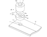
また、図10に示すように、先端の開口の向きを調整して、マイクロ流路へ注入した試料の逆流を防止したノズル100も知られている(特許文献4)。このノズル100は、先端をノズル100の長手方向に対して傾斜させて切断し、先端の傾斜する開口100aがマイクロ流路101の注入方向Aに向かうように、ノズル100を注入孔102からマイクロ流路101内に挿入する。ノズル100の先端から吐出される試料は、開口100aが向き合うマイクロ流路101の注入方向に向かって流れるので、注入孔102への逆流を防止できる。
Further, as shown in FIG. 10, a
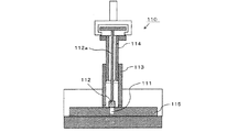
更に、図11に示すように、マイクロ流路に連通する注入孔111の開口を弁体112で塞ぎ、試料の逆流を防止したマイクロ流体システム110も知られている(特許文献5)。このマイクロ流体システム110は、マイクロ流路チップ115の注入孔111の開口周囲に筒状体からなる試料サーバ113を密着して取り付け、試料サーバ113内で加圧装置114を押し下げ、試料サーバ113に貯留した試料を所定の注入圧で注入孔111からマイクロ流路へ注入する。マイクロ流路内に試料を注入した後、弁体112と一体のロッド112aを下降させて、注入孔111を弁体112で塞ぎ、試料の逆流を防止する。
Further, as shown in FIG. 11, a
マイクロ流路の一部を狭窄若しくは閉塞して試料の逆流を防止する特許文献1乃至特許文献3に記載の逆流防止方法は、微細なマイクロ流路に対してその内径を変化させる構成を要するので、マイクロ流路のネック部や加圧部などを高精度に製造して組み立てる必要があり、構造も複雑化するので実用性に欠けていた。
The backflow prevention method described in
更に、マイクロ流路の一部に逆流防止構造を設けるので、試料の反応や混合等にマイクロ流路の全体を用いることができないという問題があった。 Further, since the backflow prevention structure is provided in a part of the microchannel, there is a problem that the entire microchannel cannot be used for the reaction and mixing of the sample.
図10に示すノズル100では、試料をマイクロ流路内に注入する際に一時的に試料の逆流を防止できるが、ノズル100を引き出した後に、注入孔102が負圧となって試料が逆流するので、試料の逆流防止という本質的な課題を解決するものではない。
The
また、図11に示すマイクロ流体システム110は、加圧装置114の動作や弁体112の開閉動作を制御する制御機構を要し、また、筒状体の試料サーバ113内で加圧装置114や弁体112を開閉するロッド112aを鉛直方向に移動させる複雑な構造であるので、システムの全体が複雑で高価のものとなり、汎用のマイクロ流路の逆流防止構造として利用することはできない。
Further, the
本発明は、このような従来の問題点を考慮してなされたものであり、簡単な構成でマイクロ流路に注入した試料の逆流を防止するアダプタを提供することを目的とする。 The present invention has been made in consideration of such conventional problems, and an object of the present invention is to provide an adapter that prevents backflow of a sample injected into a microchannel with a simple configuration.
上述の目的を達成するため、請求項1に記載のアダプタは、マイクロ流路チップのマイクロ流路へ試料を注入するピペット若しくはチューブの先端部を挿入する挿入孔が鉛直方向に貫通する筒状本体からなり、マイクロ流路チップの表面のマイクロ流路に連通する注入孔の開口周囲に筒状本体の底面を密着して取り付け、挿入孔に先端部を挿入したピペット若しくはチューブから、注入孔を介してマイクロ流路へ試料を注入するアダプタであって、挿入孔を遮断するエラストマーからなる遮断壁を備え、遮断壁は、PDMS(ポリジメチルシロキサン)を金型で成形して、筒状本体に一体に形成されるとともに、遮断壁にピペット若しくはチューブの先端部を挿抜自在とするスリットが形成されていることを特徴とする。
In order to achieve the above object, the adapter according to
マイクロ流路に連通する注入孔の開口周囲に筒状本体の底面を密着して取り付けるので、周囲が密閉された状態で注入孔と挿入孔が連通する。 Since the bottom surface of the cylindrical body is closely attached around the opening of the injection hole communicating with the micro flow path, the injection hole and the insertion hole communicate with each other in a sealed state.
エラストマーからなる遮断壁にスリットが形成されているので、スリットを押し広げてピペット若しくはチューブの先端部を遮断壁に挿抜させることができ、遮断壁を挿通させたピペット若しくはチューブの先端部から注入孔へ試料を注入できる。また、試料を注入した後、スリットからピペット若しくはチューブを引き出すと、スリットの隙間が閉じ、挿入孔は遮断壁で遮断されるので、注入孔が負圧となっても試料が逆流しない。 Since a slit is formed in the blocking wall made of elastomer, the slit can be expanded to insert and remove the tip of the pipette or tube into the blocking wall, and the injection hole is inserted from the tip of the pipette or tube through which the blocking wall is inserted. The sample can be injected into. Further, when the pipette or tube is pulled out from the slit after injecting the sample, the gap between the slits is closed and the insertion hole is blocked by the blocking wall, so that the sample does not flow back even if the injection hole becomes negative pressure.
PDMS(ポリジメチルシロキサン)は、弾性限度が高く、スリットが大きく開いてもピペット若しくはチューブを引き出せば、スリットの隙間が閉じる原形状に復帰する。 PDMS (polydimethylsiloxane) has a high elastic limit, and even if the slit is wide open, if the pipette or tube is pulled out, the original shape in which the slit gap is closed is restored.
また、スリット若しくはチューブの外周にスリットの内面が密着し、スリットの隙間から試料が漏れにくい。 Further, the inner surface of the slit is in close contact with the outer circumference of the slit or the tube, and the sample is less likely to leak from the gap of the slit.
請求項2に記載のアダプタは、挿入孔の遮断壁より上方の少なくとも一部の内径が、挿入孔に挿入するピペット若しくはチューブの先端部の外径より細いことを特徴とする。
The adapter according to
ピペット若しくはチューブの先端部は、遮断壁のスリットに到達する前に、先端部の外形より短い挿入孔の内壁に当接して、挿入孔が拡径することによりスリットで区切られる遮断壁の舌片が上方に撓み、スリットが開く。 The tip of the pipette or tube abuts on the inner wall of the insertion hole, which is shorter than the outer shape of the tip, before reaching the slit of the barrier, and the tongue piece of the barrier is separated by the slit by expanding the diameter of the insertion hole. Bends upward and the slit opens.
請求項3に記載のアダプタは、遮断壁に挿入孔の中心軸で交差する複数のスリットが形成されていることを特徴とする。
The adapter according to
挿入孔の中心軸で交差する複数のスリットにより、挿入孔に挿入するピペット若しくはチューブの先端部は、挿入孔の中心軸に沿って遮断壁を挿通するように案内される。 Multiple slits that intersect at the central axis of the insertion hole guide the tip of the pipette or tube to be inserted into the insertion hole to pass through the barrier along the central axis of the insertion hole.
請求項4に記載のアダプタは、筒状本体が、鉛直方向に積層される複数の筒部の対向する積層面間を固着して一体に形成され、遮断壁は、いずれかの筒部の積層面に沿って一体に形成されることを特徴とする。 In the adapter according to claim 4 , the tubular main body is integrally formed by fixing between the opposing laminated surfaces of a plurality of tubular portions laminated in the vertical direction, and the blocking wall is formed by laminating any of the tubular portions. It is characterized in that it is integrally formed along a surface.
遮断壁を、分離して形成するいずれかの筒部の積層面に沿って一体に形成するので、遮断壁や遮断壁に穿設するスリットを容易に形成できる。 Since the blocking wall is integrally formed along the laminated surface of any of the tubular portions that are separately formed, a slit to be formed in the blocking wall or the blocking wall can be easily formed.
請求項5に記載のアダプタは、少なくともスリットの延長方向の部位で、遮断壁が一体に形成される筒部の積層面と対向する積層面が固着されることを特徴とする。
The adapter according to
スリットの延長方向の部位で筒部の積層面間が固着され、一体化されるので、スリットにピペットやチューブの挿抜を繰り返しても、筒部の積層面間が固着された部位までスリットの裂け目が進行することがない。 Since the laminated surfaces of the cylinders are fixed and integrated at the part in the extension direction of the slit, even if the pipette or tube is repeatedly inserted and removed from the slit, the slit cracks to the part where the laminated surfaces of the cylinder are fixed. Does not progress.
請求項6に記載のアダプタは、両面に粘着層が形成された両面テープを介して、マイクロ流路チップの表面に筒状本体の底面が密着して取り付けられることを特徴とする。
The adapter according to
遮断壁にスリットを形成したアダプタを、マイクロ流路チップに対して着脱自在とするので、試料が逆流する恐れのあるマイクロ流路チップの注入孔の周囲にのみ、両面テープで筒状本体の底面を密着させて取り付けることができる。 Since the adapter with a slit in the blocking wall is removable to the microchannel tip, the bottom surface of the tubular body is covered with double-sided tape only around the injection hole of the microchannel chip where the sample may flow back. Can be attached in close contact with each other.
請求項1の発明によれば、挿入孔を遮断する遮断壁にスリットを形成する簡単な加工で、試料の逆流を防止する逆止弁を形成できる。 According to the first aspect of the present invention, a check valve for preventing backflow of a sample can be formed by a simple process of forming a slit in a blocking wall that blocks an insertion hole.
また、試料が逆流する恐れのあるマイクロ流路チップにのみ、本発明に係るアダプタを取り付ければよいので、汎用のマイクロ流路チップの逆流防止手段として用いることができる。 Further, since the adapter according to the present invention needs to be attached only to the microchannel chip in which the sample may flow back, it can be used as a backflow prevention means for the general-purpose microchannel chip.
また、筒状本体に遮断壁を一体成形するので、挿入孔を遮断する遮断壁を筒状本体の成形と同時に成形できる。 Further , since the blocking wall is integrally molded with the tubular body, the blocking wall that blocks the insertion hole can be molded at the same time as the molding of the tubular body.
また、PDMS(ポリジメチルシロキサン)からなる筒状本体は、弾性限度が高く、ピペットやチューブを挿入してスリットが大きく開いても、ピペットやチューブの外周面にスリットの内面が密着し、注入圧をかけて試料を注入しても、スリットの隙間から試料が漏れ出ない。 In addition, the tubular body made of PDMS (polydimethylsiloxane) has a high elastic limit, and even if the pipette or tube is inserted and the slit is wide open, the inner surface of the slit is in close contact with the outer peripheral surface of the pipette or tube, and the injection pressure is increased. Even if the sample is injected with a pipette, the sample does not leak from the gap of the slit.
また、筒状本体を半透明材料であるPDMS(ポリジメチルシロキサン)から成形するので、筒状本体の挿入孔へ挿入するピペットやチューブの挿入状態やピペットやチューブからマイクロ流路へ送液する試料の色や量を目視確認できる。 In addition, since the tubular body is molded from PDMS (polydimethylsiloxane), which is a translucent material, the inserted state of the pipette or tube to be inserted into the insertion hole of the tubular body or the sample to be sent from the pipette or tube to the microchannel. You can visually check the color and amount of.
請求項2の発明によれば、ピペット若しくはチューブが遮断壁に到達する前に、遮断壁に形成されたスリットが開き、ピペット若しくはチューブの先端部を容易にスリットに挿通させることができる。 According to the second aspect of the present invention, the slit formed in the blocking wall is opened before the pipette or the tube reaches the blocking wall, and the tip of the pipette or the tube can be easily inserted into the slit.
請求項3の発明によれば、ピペット若しくはチューブの先端部が、挿入孔の中心軸に沿って遮断壁を挿通するように案内されるので、その先端を注入孔の開口の上方に位置決めしやすく、注入孔へ確実に試料を注入できる。 According to the third aspect of the invention, since the tip of the pipette or tube is guided so as to pass through the blocking wall along the central axis of the insertion hole, it is easy to position the tip above the opening of the injection hole. , The sample can be reliably injected into the injection hole.
請求項4の発明によれば、挿入孔の中間で挿入孔を遮断する遮断壁や、遮断壁に穿設するスリットを、分離して形成する筒部の端面である積層面に沿って形成するので、それぞれ容易に形成できる。 According to the invention of claim 4 , a blocking wall for blocking the insertion hole in the middle of the insertion hole and a slit formed in the blocking wall are formed along the laminated surface which is the end surface of the tubular portion to be separately formed. Therefore, each can be easily formed.
請求項5の発明によれば、スリットにピペットやチューブの挿抜を繰り返しても、スリットの裂け目が進行しない。
According to the invention of
請求項6の発明によれば、両面に粘着層が形成された両面テープを介して、マイクロ流路チップの表面に筒状本体の底面が密着して取り付けられるので、試料が逆流する恐れのある注入孔の周囲にのみアダプタを着脱自在に取り付け、遮断壁にスリットが形成されたアダプタを再利用できる。
According to the invention of
以下、本発明の第1実施の形態に係るアダプタ1を、図1乃至図3を用いて説明する。以下の本明細書中の説明では、図1に図示する各方向を上下左右方向として各部の構成を説明する。このアダプタ1は、有機化合物、生体試料などの微量試料を先端から吐出するピペット50と、幅及び深さが500nm乃至1mmのマイクロ流路14内に注入される試料を混合、反応、合成、抽出、分離、若しくは分析するマイクロ流路チップ10とを連結するもので、アダプタ1に挿入されるピペット50からマイクロ流路14へ試料を注入するために、マイクロ流路14に連通する注入孔11の注入口11aの周囲に起立して取り付けられる。
Hereinafter, the
各図に示すように、アダプタ1は、PDMS(ポリジメチルシロキサン)を成形材料とする金型を用いたインジェクション成形で、挿入孔3が鉛直方向に貫通することにより円筒状に形成された筒状本体2と後述する遮断壁5とから構成されている。ここではインジェクション成形で筒状本体2を成形しているが、トランスファー成形、コンプレッション成形等の任意の製造方法で製造できる。
As shown in each figure, the
図1に示すように、挿入孔3の中間位置に、挿入孔3を横断して遮断する遮断壁5が筒状本体2に一体に形成されている。また、この遮断壁5には、挿入孔3の中心軸が通過する位置で互いに直交して交差し、それぞれ遮断壁5の上面から下面にかけて縦断する2本のスリット6、6が穿設されている。各スリット6の両端は、遮断壁5と筒状本体2との境界位置まで達し、従って、遮断壁5は、直交する2本のスリット6、6で区切られる4枚の扇状の舌片5aで構成される。上述のように、遮断壁5もエラストマーのPDMS(ポリジメチルシロキサン)から成形されるので、4枚の舌片5aは、筒状本体2との境界で片持ち支持される弾性片として作用し、外力を受けない自由状態では全ての隣り合う舌片5a、5a間が密着してスリット6、6の隙間が閉じられ、挿入孔3は、遮断壁5で遮断される。
As shown in FIG. 1, a blocking
アダプタ1を用いて試料を注入するマイクロ流路チップ10は、下層基板17の上面に、マイクロ流路14が露出する上層基板16の下面を対向させて、下層基板17と上層基板16の対向面間を固着して製造され、上層基板16の上面であるマイクロ流路チップ10の表面に、マイクロ流路14に連通する注入孔11の注入口11aが開口している。
In the
アダプタ1は、挿入孔3の中心軸が注入口11aを貫通するマイクロ流路チップ10の表面10a上の位置に起立する姿勢で、筒状本体2の底面2aが注入口11aの周囲全体の表面10aに密着する状態で、アダプタ1の底面2aとマイクロ流路チップ10の表面10a間を固着して取り付けられる。
The
筒状本体2の底面2aと注入口11aの周囲の表面10aとの固着は、接着剤を用いて固着してもよいが、ここでは、相互に接する筒状本体2の底面2aとマイクロ流路チップ10の表面10aにプラズマを照射するプラズマ処理若しくはエキシマ処理等を行い、表面改質によって両者を一体に接合する。
The
筒状本体2の底面2aとマイクロ流路チップ10の表面10aが表面改質されることによって、図1に示すように、筒状本体2は、挿入孔3がマイクロ流路チップ10の注入孔11に連通し、連通する周囲全体を密封させた状態で、マイクロ流路チップ10の表面10a上に起立して取り付けられる。
As shown in FIG. 1, the
以下、このように構成されたアダプタ1を用いて、ピペット50からマイクロ流路14へ試料を注入する際のアダプタ1の作用について説明する。ピペット50を挿入孔3へ挿入する前の待機状態では、図1、図2に示すように、スリット6で区切られた4枚の舌片5aは外力を受けていないので、隣り合う舌片5a、5a間が密着してスリット6、6の隙間が閉じられている。
Hereinafter, the operation of the
ピペット50からマイクロ流路14へ試料を注入する場合には、マイクロ流路チップ10の表面10aに起立するアダプタ1の挿入孔3の上方の開口から、ピペット50の先端部50aを挿入する。この挿入の際に、筒状本体2は、弾性限度が高いPDMS(ポリジメチルシロキサン)から形成されているので、中心軸が鉛直方向となっている挿入孔3に対して、傾斜する方向からピペット50を挿入しても、挿入孔3が挿入方向に一致するように筒状本体2が弾性変形し、筒状本体2に無理な外力が加わって破損することがない。
When the sample is injected from the
ピペット50の先端部50aをアダプタ1の挿入孔3内を下方へ挿入していくと、先端部50aが遮断壁5に当接し、舌片5aを下方へ押し込みスリット6を広げながら遮断壁5を挿通する。互いに直交して遮断壁5に穿設される2本のスリット6、6は、挿入孔3の中心軸が通過する位置で交差しているので、ピペット50の先端部50aは、各スリット6を広げる過程で、挿入孔3の中心軸で遮断壁5を挿通するように案内され、ピペット50の先端部50aが遮断壁5を挿通した図3に示す挿入位置では、注入孔11の注入口11aの上方に位置している。
When the
挿通孔3と注入孔11が連通する周囲は密閉されているので、ピペット50の先端部50aから注入口11aに試料を落下させ、若しくは、所定の注入圧をかけてピペット50の先端部50aから注入口11aに試料を注入することにより、マイクロ流路14へ試料が注入される。
Since the periphery where the
必要な全量の試料を注入した後、ピペット50の先端部50aを挿入孔3から上方に引き抜くと、PDMS(ポリジメチルシロキサン)で形成された4枚の舌片5a、5aは、隣り合う舌片5a、5a間が密着する待機状態の形状に復帰し、スリット6、6の隙間が閉じられた遮断壁5によって挿通孔3が遮断される。その結果、挿入孔3からピペット50を引き抜くことにより、挿入孔3内がマイクロ流路14の内圧に比べて負圧になるが、マイクロ流路14に注入された試料が挿入孔3へ逆流することがない。
After injecting the required total amount of sample, the
次に、本発明の第2実施の形態に係るアダプタ20を、図4乃至図9を用いて説明する。第2実施の形態の説明において、第1実施の形態に係るアダプタ1の構成と同一若しくは同様に作用する構成については、同一番号を付してその詳細な説明を省略する。
Next, the
第2実施の形態に係るアダプタ20は、外形が同一の円筒形で円筒の長さが異なる上部筒部25と下部筒部26とが、それぞれPDMS(ポリジメチルシロキサン)を成形材料として、個別に金型を用いて成形され、図4に示すように、鉛直方向に積層させた上部筒部25と下部筒部26の対向する積層面25a、26a間の固着部29を固着して、一体の円筒形の筒状本体21としている。
In the
図4、図7に示すように、下部筒部26を成形する際に、下部筒部26を貫通する挿入孔3の上端、すなわち、下部筒部26の上面である積層面26aに沿って、挿入孔3を遮断する遮断壁27が一体に形成されている。
As shown in FIGS. 4 and 7, when the lower
この遮断壁27にも、挿入孔3の中心軸が通過する位置で互いに直交して交差し、それぞれ遮断壁27の上面から下面にかけて縦断する2本のスリット28、28が穿設されている。各スリット28の両端は、上部筒部25の積層面25aと下部筒部26の積層面26a間の固着部29との境界位置(図4で破線で示す位置)まで達し、遮断壁27は、直交する2本のスリット28、28で区切られる4枚の扇状の舌片27aで構成される。4枚の舌片27aは、固着部29を基端として片持ち支持される弾性片として作用し、外力を受けない自由状態では全ての隣り合う舌片27a、27a間が密着してスリット28、28の隙間が閉じられ、挿入孔3は、遮断壁27により遮断される。
The blocking
本実施の形態では、遮断壁27を個別に形成する下部筒部26の端部に形成するので、挿入孔3の中間位置で挿入孔3を遮断する遮断壁27を筒状本体21に容易に形成することができ、また、遮断壁27を上面から下面にかけて縦断するスリット28も、遮断壁27の上面若しくは下面のいずれかを支持し、他方の面から容易に穿設して形成できる。
In the present embodiment, since the blocking
図7に示すように、上部筒部25を貫通する挿入孔3の上端の開口縁は、ピペット50の先端部50aを挿入孔3内に案内する緩やかな湾曲面25bとなっていて、また、この挿入孔3の内方の内壁面には、挿入孔3の中心軸周りにリブが一体に突設されることにより、内径をその上下の挿入孔3の内径より小径とした括れ部24が形成されている。括れ部24の内径は、先端が遮断壁27に達する前のピペット50の先端部50aの外径より細く、これにより、後述するように、ピペット50の先端部50aを挿入孔3へ挿入すると、括れ部24の内径が拡径し、筒状本体21の上方が挿入孔3の中心軸から外側に湾曲するとともに、括れ部24により、ピペット50の先端部50aが鉛直方向の中心軸に沿って支持される。
As shown in FIG. 7, the opening edge of the upper end of the
固着部29における上部筒部25と下部筒部26間の固着は、ここでは接着剤を介して一体に接合するが、加熱溶着や、第1実施の形態と同様に積層面25a、26a間の表面改質処理など一体に接合できれば任意の固着手段を採用できる。
The fixing between the
上部筒部25と下部筒部26が一体となったアダプタ20の筒状本体21は、両面に粘着層が形成された両面テープ7を介して、挿入孔3の中心軸が注入口11aを貫通するマイクロ流路チップ10の表面10a上の位置に起立する姿勢で取り付けられる。アダプタ20をマイクロ流路チップ10に取り付けた状態で、両面テープ7は、筒状本体21の底面21aと注入口11aの周囲全体の表面10aとに密着するので、挿入孔3と注入孔11が連通する周囲が密閉される。
In the
両面テープ7を用いて、アダプタ20を着脱自在にマイクロ流路チップ10の表面10aに取り付けるので、アダプタ20を試料の逆流が生じる恐れのあるマイクロ流路チップ10にのみ取り付ける汎用のアダプタとして用いることができる。
Since the
以下、ピペット50からマイクロ流路14へ試料を注入する際のアダプタ20の作用について説明する。ピペット50を挿入孔3へ挿入する前の待機状態では、図5、図7に示すように、スリット28で区切られた4枚の舌片27aは外力を受けていないので、隣り合う舌片27a、27a間が密着してスリット28、28の隙間が閉じられている。
Hereinafter, the operation of the
ピペット50からマイクロ流路14へ試料を注入する場合には、図8に示すようにアダプタ20の挿入孔3の上方の開口から、ピペット50の先端部50aを挿入する。ピペット50を挿入する過程で、遮断壁27より上方の挿入孔3の中間位置には、内径がピペット50の先端部50aの外径より細い括れ部24が形成されているので、図8に示すように、ピペット50が遮断壁27に達する前に、ピペット50の先端部50aが括れ部24に当接し、筒状本体21の上方の全体が拡径方向に湾曲する。筒状本体21の上方が、挿入孔3の中心軸から半径方向に撓むことによって、基端が筒状本体21に片持ち支持されている4枚の舌片27aは、それぞれ基端から先端(自由端)に向かって上方に傾斜し、各先端の間にピペット50の先端部50aを挿通する隙間が形成され、スリット28が開く。
When the sample is injected from the
従って、開いたスリット28の隙間へピペット50の先端部50aを挿入し、遮断壁27を容易に挿通させることができる。更に、ピペット50の先端部50aをアダプタ20の遮断壁27の下方まで挿入した図9に示す挿入位置では、挿入孔3の中心軸で直交する2本のスリット28と、その上方の括れ部24の2カ所の位置で、ピペット50の先端部50aが、挿入孔3の中心軸に沿った鉛直方向に支持されるので、ピペット50の先端部50aは、注入孔11の注入口11aの上方に位置している。
Therefore, the
挿通孔3と注入孔11が連通する周囲は両面テープ7が密着して密閉されているので、ピペット50の先端部50aから注入口11aに試料を落下させ、若しくは、所定の注入圧をかけてピペット50の先端部50aから注入口11aに試料を注入することにより、マイクロ流路14へ試料が注入される。
Since the double-
必要な全量の試料を注入した後、ピペット50の先端部50aを挿入孔3の括れ部27から上方に引き抜くまでは、4枚の舌片27aの先端の間に隙間が生じているので、遮断壁27から容易に引き抜くことができ、ピペット50の先端部50aを括れ部27から上方に完全に引き抜くと、PDMS(ポリジメチルシロキサン)で形成された4枚の舌片27aが待機状態の原形状に復帰し、スリット28、28の隙間が閉じられた遮断壁27によって挿通孔3が遮断される。その結果、挿入孔3内が一時的にマイクロ流路14の内圧に比べて負圧になっても、マイクロ流路14に注入された試料が挿入孔3へ逆流することがない。
After injecting the required total amount of sample, until the
このアダプタ20によれば、遮断壁27に穿設されたスリット28、28の延長方向に、上部筒部25と下部筒部26間を固着する固着部29が存在するので、スリット28へのピペット50の先端部50aの挿抜を繰り返しても、スリット28の裂け目は固着部29より先に進むことがない。
According to this
上述の実施の形態においては、ピペット50をアダプタ1、20の挿入孔へ挿入する例で説明したが、加圧ポンプなどに接続するチューブをアダプタ1、20の挿入孔へ挿入し、チューブの先端から試料をマイクロ流路14へ注入するものであってもよい。
In the above-described embodiment, the example of inserting the
また、遮断壁5、27は、エラストマーであれば任意の材料で形成することができ、必ずしも、アダプタ1、20の筒状本体2、21と同一の材料とする必要はない。
Further, the
また、筒状本体は、鉛直方向に積層させた3個以上の筒部の積層面間を固着して一体に形成してもよく、更に、中心側を遮断壁とする扁平な円板の遮断壁とする部分にスリットを穿設しておき、円板の上下に上部筒部と下部筒部を積層させて、遮断壁を除く積層面間を固着し、筒状本体としてもよい。 Further, the tubular main body may be integrally formed by fixing the laminated surfaces of three or more cylindrical portions laminated in the vertical direction, and further, a flat disk having a blocking wall on the center side is blocked. A slit may be formed in a portion to be a wall, and an upper cylinder portion and a lower cylinder portion may be laminated on the upper and lower sides of the disk to fix the laminated surfaces excluding the blocking wall to form a tubular main body.
また、筒状本体を貫通する挿入孔の形状は、横断面が四角形の角筒形等その形状は円筒形に限らない。例えば、挿入孔の横断面の形状を四角形とすれば、遮断壁に穿設するスリットで分離される舌片は、直線上の基端で挿入孔の内壁面に片持ち支持され、舌片に捻り応力が生じることなく、低挿入力でピペットやチューブの先端部を挿通させることができる。 Further, the shape of the insertion hole penetrating the tubular body is not limited to a cylindrical shape, such as a square tubular shape having a rectangular cross section. For example, if the cross-sectional shape of the insertion hole is quadrangular, the tongue piece separated by the slit formed in the blocking wall is cantilevered on the inner wall surface of the insertion hole at the base end on a straight line and becomes the tongue piece. The tip of a pipette or tube can be inserted with a low insertion force without causing torsional stress.
また、遮断壁に形成するスリットの本数や形状は、上述の実施の形態に限らず、ピペットやチューブの先端部の外形や挿入孔の形状に合わせて任意に選択できる。 Further, the number and shape of the slits formed in the barrier wall are not limited to the above-described embodiment, and can be arbitrarily selected according to the outer shape of the tip of the pipette or tube and the shape of the insertion hole.
マイクロ流路から注入した試料が逆流する恐れのあるマイクロ流路チップに取り付けるアダプタに適している。 Suitable for adapters attached to microchannel chips where samples injected from the microchannel may flow back.
1、20 アダプタ
2、21 筒状本体
2a、21a 筒状本体の底面
3 挿入孔
5、27 遮断壁
6、28 スリット
7 両面テープ
10 マイクロ流路チップ
10a マイクロ流路チップの表面
11 注入孔
11a 注入口
14 マイクロ流路
24 括れ部
25 上部筒部
25a 積層面
26 下部筒部
26a 積層面
29 固着部
1, 20
Claims (6)
マイクロ流路チップの表面のマイクロ流路に連通する注入孔の開口周囲に筒状本体の底面を密着して取り付け、
挿入孔に先端部を挿入したピペット若しくはチューブから、注入孔を介してマイクロ流路へ試料を注入するアダプタであって、
前記挿入孔を遮断するエラストマーからなる遮断壁を備え、
前記遮断壁は、PDMS(ポリジメチルシロキサン)を金型で成形して、前記筒状本体に一体に形成されるとともに、
前記遮断壁に前記ピペット若しくはチューブの先端部を挿抜自在とするスリットが形成されていることを特徴とするアダプタ。 Microchannel The insertion hole for inserting the tip of a pipette or tube that injects a sample into the microchannel of the tip consists of a cylindrical body that penetrates vertically.
Attach the bottom surface of the cylindrical body in close contact with the opening of the injection hole that communicates with the microchannel on the surface of the microchannel chip.
An adapter that injects a sample from a pipette or tube with the tip inserted into the insertion hole into the microchannel through the injection hole.
A blocking wall made of an elastomer that blocks the insertion hole is provided.
The barrier wall is formed by molding PDMS (polydimethylsiloxane) with a mold and integrally formed with the cylindrical body.
An adapter characterized in that a slit is formed in the barrier wall so that the tip of the pipette or tube can be inserted and removed.
前記遮断壁は、いずれかの前記筒部の積層面に沿って一体に形成されることを特徴とする請求項1乃至請求項3のいずれか1項に記載のアダプタ。 The tubular main body is integrally formed by fixing between the opposing laminated surfaces of a plurality of tubular portions that are laminated in the vertical direction.
The adapter according to any one of claims 1 to 3 , wherein the blocking wall is integrally formed along the laminated surface of any of the tubular portions.
Priority Applications (1)
| Application Number | Priority Date | Filing Date | Title |
|---|---|---|---|
| JP2018099478A JP6957412B2 (en) | 2018-05-24 | 2018-05-24 | adapter |
Applications Claiming Priority (1)
| Application Number | Priority Date | Filing Date | Title |
|---|---|---|---|
| JP2018099478A JP6957412B2 (en) | 2018-05-24 | 2018-05-24 | adapter |
Publications (3)
| Publication Number | Publication Date |
|---|---|
| JP2019203806A JP2019203806A (en) | 2019-11-28 |
| JP2019203806A5 JP2019203806A5 (en) | 2020-03-05 |
| JP6957412B2 true JP6957412B2 (en) | 2021-11-02 |
Family
ID=68726737
Family Applications (1)
| Application Number | Title | Priority Date | Filing Date |
|---|---|---|---|
| JP2018099478A Active JP6957412B2 (en) | 2018-05-24 | 2018-05-24 | adapter |
Country Status (1)
| Country | Link |
|---|---|
| JP (1) | JP6957412B2 (en) |
Family Cites Families (5)
| Publication number | Priority date | Publication date | Assignee | Title |
|---|---|---|---|---|
| ES266599Y (en) * | 1982-06-18 | 1983-11-16 | "DEVICE APPLICABLE TO THE CONDUCT OF ANALYSIS". | |
| JPS59133877A (en) * | 1983-01-18 | 1984-08-01 | Terumo Corp | Valve element |
| US5123443A (en) * | 1990-12-21 | 1992-06-23 | Millipore Corporation | Fluid delivery system |
| EP2730308B1 (en) * | 2011-07-04 | 2016-12-28 | Terumo Kabushiki Kaisha | Introducer sheath |
| JP5866470B1 (en) * | 2015-05-01 | 2016-02-17 | 株式会社朝日Fr研究所 | Check valve and microchemical chip using the same |
-
2018
- 2018-05-24 JP JP2018099478A patent/JP6957412B2/en active Active
Also Published As
| Publication number | Publication date |
|---|---|
| JP2019203806A (en) | 2019-11-28 |
Similar Documents
| Publication | Publication Date | Title |
|---|---|---|
| US8697010B2 (en) | Dispensing device | |
| US20150137015A1 (en) | Connector for microfluidic device, a method for injecting fluid into microfluidic device using the connector and a method of providing and operating a valve | |
| EP2308589B1 (en) | Microfluid structure | |
| WO2004087322A3 (en) | Fluid partitioning in multiple microchannels | |
| ATE336298T1 (en) | MICROSTRUCTURED PLATFORM FOR THE STUDY OF A LIQUID | |
| US20050093087A1 (en) | Microstructured device for removable storage of small amounts of liquid and a process for removal of the liquid stored in this device | |
| SG149889A1 (en) | Multilayer hydrodynamic sheath flow structure | |
| WO2003098218A1 (en) | Multi-channel microfluidic system design with balanced fluid flow distribution | |
| EP1866620A1 (en) | Apparatus for filling a sample volume defining device | |
| JP6957412B2 (en) | adapter | |
| US20170261138A1 (en) | Fluid connection ports | |
| CN107475070B (en) | Microfluidic chip and method for preparing cell droplets | |
| EP3406340A1 (en) | Flow cell with housing component | |
| RU2554573C2 (en) | Mixer with zero dead volume and method of mixing | |
| Van Swaay et al. | A chip-to-world connector with a built-in reservoir for simple small-volume sample injection | |
| WO2018001647A1 (en) | Flow cell having a reagent reservoir | |
| US9987630B2 (en) | Fluid handling device and method of using the same | |
| US10843197B2 (en) | Fluidic connector, microfluidic chip cartridge, and fluidic connector assembly thereof | |
| JP2010540267A (en) | Mounting method of microfluidic channel | |
| US11291993B2 (en) | Micro-fluid chip | |
| KR101486413B1 (en) | Microfluidic Chip Using Micro-post And Fabricating Method Thereof | |
| EP1407820A1 (en) | flap septum | |
| EP3875574B1 (en) | Micro-fluid chip and micro-fluid device | |
| KR102221834B1 (en) | Fluid valve | |
| WO2020183938A1 (en) | Microchannel chip |
Legal Events
| Date | Code | Title | Description |
|---|---|---|---|
| A521 | Written amendment |
Free format text: JAPANESE INTERMEDIATE CODE: A523 Effective date: 20200121 |
|
| A621 | Written request for application examination |
Free format text: JAPANESE INTERMEDIATE CODE: A621 Effective date: 20200121 |
|
| A977 | Report on retrieval |
Free format text: JAPANESE INTERMEDIATE CODE: A971007 Effective date: 20210129 |
|
| A131 | Notification of reasons for refusal |
Free format text: JAPANESE INTERMEDIATE CODE: A131 Effective date: 20210302 |
|
| A521 | Written amendment |
Free format text: JAPANESE INTERMEDIATE CODE: A523 Effective date: 20210421 |
|
| TRDD | Decision of grant or rejection written | ||
| A01 | Written decision to grant a patent or to grant a registration (utility model) |
Free format text: JAPANESE INTERMEDIATE CODE: A01 Effective date: 20210928 |
|
| A61 | First payment of annual fees (during grant procedure) |
Free format text: JAPANESE INTERMEDIATE CODE: A61 Effective date: 20211006 |
|
| R150 | Certificate of patent or registration of utility model |
Ref document number: 6957412 Country of ref document: JP Free format text: JAPANESE INTERMEDIATE CODE: R150 |