JP6957121B2 - Drain processing device for engine compressor - Google Patents
Drain processing device for engine compressor Download PDFInfo
- Publication number
- JP6957121B2 JP6957121B2 JP2018235984A JP2018235984A JP6957121B2 JP 6957121 B2 JP6957121 B2 JP 6957121B2 JP 2018235984 A JP2018235984 A JP 2018235984A JP 2018235984 A JP2018235984 A JP 2018235984A JP 6957121 B2 JP6957121 B2 JP 6957121B2
- Authority
- JP
- Japan
- Prior art keywords
- drain
- way valve
- separator
- engine
- port
- Prior art date
- Legal status (The legal status is an assumption and is not a legal conclusion. Google has not performed a legal analysis and makes no representation as to the accuracy of the status listed.)
- Active
Links
- XLYOFNOQVPJJNP-UHFFFAOYSA-N water Substances O XLYOFNOQVPJJNP-UHFFFAOYSA-N 0.000 claims description 14
- 238000001816 cooling Methods 0.000 claims description 4
- 239000002184 metal Substances 0.000 claims description 3
- 239000003921 oil Substances 0.000 description 18
- 239000004677 Nylon Substances 0.000 description 9
- 229920001778 nylon Polymers 0.000 description 9
- 210000002445 nipple Anatomy 0.000 description 7
- 238000007710 freezing Methods 0.000 description 6
- 230000008014 freezing Effects 0.000 description 6
- 230000003584 silencer Effects 0.000 description 6
- 238000007906 compression Methods 0.000 description 2
- 239000010725 compressor oil Substances 0.000 description 2
- 238000010586 diagram Methods 0.000 description 2
- 239000000428 dust Substances 0.000 description 2
- 238000005192 partition Methods 0.000 description 2
- 230000002093 peripheral effect Effects 0.000 description 2
- 229910000831 Steel Inorganic materials 0.000 description 1
- 230000006835 compression Effects 0.000 description 1
- 238000010276 construction Methods 0.000 description 1
- 230000007797 corrosion Effects 0.000 description 1
- 238000005260 corrosion Methods 0.000 description 1
- 238000007599 discharging Methods 0.000 description 1
- 230000000694 effects Effects 0.000 description 1
- 230000001050 lubricating effect Effects 0.000 description 1
- 230000014759 maintenance of location Effects 0.000 description 1
- 230000001105 regulatory effect Effects 0.000 description 1
- 239000010959 steel Substances 0.000 description 1
Images


Classifications
-
- Y—GENERAL TAGGING OF NEW TECHNOLOGICAL DEVELOPMENTS; GENERAL TAGGING OF CROSS-SECTIONAL TECHNOLOGIES SPANNING OVER SEVERAL SECTIONS OF THE IPC; TECHNICAL SUBJECTS COVERED BY FORMER USPC CROSS-REFERENCE ART COLLECTIONS [XRACs] AND DIGESTS
- Y02—TECHNOLOGIES OR APPLICATIONS FOR MITIGATION OR ADAPTATION AGAINST CLIMATE CHANGE
- Y02T—CLIMATE CHANGE MITIGATION TECHNOLOGIES RELATED TO TRANSPORTATION
- Y02T10/00—Road transport of goods or passengers
- Y02T10/10—Internal combustion engine [ICE] based vehicles
- Y02T10/12—Improving ICE efficiencies
Landscapes
- Compressor (AREA)
Description
本発明は、工事現場等において機器に圧縮空気を供給するエンジンコンプレッサにおいて、圧縮空気から分離されたドレンを処理するためのエンジンコンプレッサのドレン処理装置に関するものである。 The present invention relates to a drain processing device for an engine compressor for processing drain separated from compressed air in an engine compressor that supplies compressed air to equipment at a construction site or the like.
エンジンコンプレッサは、エンジンでコンプレッサ本体を駆動して空気を圧縮し、得られた圧縮空気をレシーバタンクに溜めるとともに、該レシーバタンクの下流側にオイルセパレータとアフタクーラを接続して、圧縮空気中のオイル分や水分をドレンとして分離させ、それをドレンセパレータで分離して外部に排出するようにしている。 The engine compressor drives the compressor body with the engine to compress the air, stores the obtained compressed air in the receiver tank, and connects an oil separator and an aftercooler to the downstream side of the receiver tank to connect the oil in the compressed air. Minutes and water are separated as drain, which is separated by a drain separator and discharged to the outside.
従来のドレン排出装置は、例えば、特許文献1に示されるように、ドレンセパレータで分離されたドレンを下方に流下させてドレンタンクに溜め、その底部に設けた排出口から外部に排出するようにしている。その際、ドレンは圧縮空気と共に排出されるので、ドレンが飛散して周辺部を汚染するとともに排出による騒音が発生してしまう。そこで、上記従来のドレン排出装置では、ドレンタンク内に消音器を設けるとともに、ドレンタンク内のドレンは、排出管を通して貯溜タンクに排出するようにしていた。 In the conventional drain discharge device, for example, as shown in Patent Document 1, the drain separated by the drain separator flows downward, is stored in the drain tank, and is discharged to the outside from the discharge port provided at the bottom thereof. ing. At that time, since the drain is discharged together with the compressed air, the drain scatters and pollutes the peripheral portion, and noise due to the discharge is generated. Therefore, in the above-mentioned conventional drain discharge device, a silencer is provided in the drain tank, and the drain in the drain tank is discharged to the storage tank through the discharge pipe.
このようにすれば、騒音を抑えながら、ドレンを周辺部に飛散させることなく貯溜タンクに排出することができる。 In this way, it is possible to discharge the drain to the storage tank without scattering the drain to the peripheral portion while suppressing noise.
しかしながら、上記従来のドレン処理装置では、ドレンタンクと消音器、及び専用の貯溜タンクが必要になり、その分、部品点数が多くなって構造が複雑になってしまうとい
う問題点があった。また、上記従来のドレン排出装置では、ドレンが流れにくい消音器を内蔵しているため、運転停止後には、ドレン配管にドレンが残ってしまい、寒冷時には、ドレン配管に残ったドレンが凍結してドレン配管が破損するおそれがあるという問題点もあった。
However, the above-mentioned conventional drain treatment apparatus requires a drain tank, a silencer, and a dedicated storage tank, which causes a problem that the number of parts increases and the structure becomes complicated. Further, since the above-mentioned conventional drain discharge device has a built-in silencer that makes it difficult for drain to flow, the drain remains in the drain pipe after the operation is stopped, and the drain remaining in the drain pipe freezes in cold weather. There is also a problem that the drain pipe may be damaged.
本発明は、そのような問題点に鑑み、ドレンタンク,消音器、及び専用の貯溜タンク等を不要とし、また、コンプレッサの運転停止後、ドレン配管内にドレンが残らないようにして、寒冷時にもドレンの凍結による配管の破損を防止することを目的とするものである。 In view of such a problem, the present invention eliminates the need for a drain tank, a silencer, a dedicated storage tank, etc., and prevents the drain from remaining in the drain pipe after the operation of the compressor is stopped, so that the drain does not remain in the drain pipe in cold weather. The purpose is to prevent damage to the piping due to freezing of the drain.
前記課題を解決するため、本願の請求項1にかかる発明は、エンジンと、該エンジンにより駆動されるコンプレッサ本体とを金属製の筐体の内部に収納し、該筐体をベースの上に設置したエンジンコンプレッサの機内に、前記コンプレッサ本体で圧縮された空気を溜めるレシーバタンクと、該レシーバタンクの下流側に設けられ、前記レシーバタンクから排出される圧縮空気のオイル分を分離するオイルセパレータと、該オイルセパレータからの圧縮空気を冷却するアフタクーラと、該アフタクーラにより冷却凝縮された水分と、残ったオイル分をドレンとして排除するドレンセパレータとを備え、前記ドレンセパレータで排除された前記ドレンを前記エンジンのマフラ内に流入させ、前記ドレンを前記エンジンの排熱により処理するようにした前記エンジンコンプレッサのドレン処理装置であって、前記ドレンセパレータから前記マフラまでのドレン排出経路中に三方弁を配設し、該三方弁の一つのポートを入口ポートとし、該入口ポートを前記ドレンセパレータのドレン排出口と連結し、前記三方弁の残りのポートの内の一方を第1の出口ポートとし、該第1の出口ポートを前記マフラと連結し、前記三方弁の残りの一つのポートを第2の出口ポートとし、該第2の出口ポートを外部排出口へ連結したことを特徴とする。 In order to solve the above problems, in the invention according to claim 1 of the present application, an engine and a compressor main body driven by the engine are housed inside a metal housing, and the housing is installed on a base. A receiver tank that stores the air compressed by the compressor body and an oil separator that is provided on the downstream side of the receiver tank and separates the oil content of the compressed air discharged from the receiver tank in the engine compressor. and aftercooler for cooling the compressed air from the oil separator, and water cooled condenser by the aftercooler, residual oil fraction and a drain separator to eliminate as a drain, the said drain which is eliminated by the drain separator engine A drain treatment device for the engine compressor in which the drain is treated by the exhaust heat of the engine, and a three-way valve is arranged in the drain discharge path from the drain separator to the muffler. Then, one port of the three-way valve is used as an inlet port, the inlet port is connected to the drain discharge port of the drain separator, and one of the remaining ports of the three-way valve is used as a first outlet port. The outlet port of 1 is connected to the muffler, the remaining one port of the three-way valve is used as a second outlet port, and the second outlet port is connected to an external discharge port .
また、本願の請求項2にかかる発明は、請求項1にかかる発明において、前記三方弁の第2の出口ポートを、前記ベースの壁に設けたボスに直接接続したことを特徴とする。
The invention according to
また、本願の請求項3にかかる発明は、請求項1にかかる発明において、前記三方弁の入口ポートを、前記ドレンセパレータの前記ドレン排出口に直接接続したことを特徴とする。 The invention according to claim 3 of the present application is characterized in that, in the invention according to claim 1 , the inlet port of the three-way valve is directly connected to the drain discharge port of the drain separator .
本発明は、次のような効果を奏する。
すなわち、請求項1にかかる発明においては、ドレンセパレータで排除されたドレンをエンジンのマフラ内に流入させ、ドレンをエンジンの排熱により処理するようにしたので、ドレンセパレータの排出口で一時的にドレンを受けるドレンタンクは不要となる。また、ドレンセパレータの排出口から吐出される圧縮空気による騒音も、マフラ内で吸収されるので消音器も不要となる。また、ドレンはすべてマフラ内で処理されて外部には排出されないため、ドレンを溜めておくための専用の貯溜タンクも不要となる。さらに、前記ドレンセパレータから前記マフラまでのドレン排出経路中に三方弁を配設し、該三方弁の入口ポートを前記ドレンセパレータのドレン排出口と連結し、前記三方弁の第1の出口ポートを前記マフラと連結し、前記三方弁の第2の出口ポートを外部排出口へ連結したので、寒冷時、運転停止後に、三方弁を外部排出口側に切り替えることにより、ドレンセパレータやその下流配管内の水抜きができ、凍結を防止できる。
The present invention has the following effects.
That is, in the invention according to claim 1, since the drain removed by the drain separator is allowed to flow into the muffler of the engine and the drain is treated by the exhaust heat of the engine, the drain is temporarily treated at the discharge port of the drain separator. The drain tank that receives the drain is no longer required. Further, the noise generated by the compressed air discharged from the discharge port of the drain separator is also absorbed in the muffler, so that a silencer is not required. In addition , since all the drain is processed in the muffler and not discharged to the outside, a dedicated storage tank for storing the drain is not required. Further, a three-way valve is arranged in the drain discharge path from the drain separator to the muffler, the inlet port of the three-way valve is connected to the drain discharge port of the drain separator, and the first outlet port of the three-way valve is connected. Since it was connected to the muffler and the second outlet port of the three-way valve was connected to the external discharge port, the three-way valve could be switched to the external discharge port side in cold weather or after the operation was stopped, so that the drain separator and its downstream piping could be used. Can drain water and prevent freezing.
また、請求項2にかかる発明においては、請求項1にかかるエンジンコンプレッサのドレン処理装置において、三方弁の第2の出口ポートを、ベースの壁に設けたボスに直接接続したので、三方弁の第2の出口ポートが、ドレンセパレータのドレン排出口より低い
位置になって、三方弁を外部排出口側に切り替えたとき、ドレンが自重で流れて容易に排出される。
Further, in the invention according to
When the three-way valve is switched to the external discharge port side at the position, the drain flows by its own weight and is easily discharged .
また、請求項3にかかる発明においては、請求項1にかかるエンジンコンプレッサのドレン処理装置において、前記三方弁の入口ポートを、ドレンセパレータのドレン排出口に直接接続したので、ドレンセパレータと三方弁とが一体化され、アフタクーラへの取付が容易になる。また、三方弁の第2の出口ポートの排出先を自由な場所に設置でき、省スペース化がしやすくなる。 Further, in the invention according to claim 3, in the drain processing device of the engine compressor according to claim 1 , since the inlet port of the three-way valve is directly connected to the drain discharge port of the drain separator, the drain separator and the three-way valve are used. Is integrated, making it easy to attach to the aftercooler. In addition, the discharge destination of the second outlet port of the three-way valve can be installed in a free place, which facilitates space saving.
以下、本発明の実施例を図面に基づいて詳細に説明する。 Hereinafter, examples of the present invention will be described in detail with reference to the drawings.
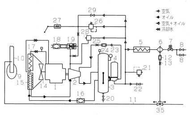
図1は、本発明の第1実施例に係るドレン処理装置の配管接続図である。図1において、符号1はエンジン、2はコンプレッサ本体、3はレシーバタンク、4はオイルセパレータ、5はアフタクーラ、6はドレンセパレータ、7は保圧弁、8はサービスバルブ、9はマフラ、10はマフラ入口管、11はドレン処理用配管、12はフィルタ、13はオリフィス、14はファン、15はオイルクーラ、16はオイルフィルタ、17はラジエータ、18はエアクリーナ、19は吸気調整弁、20はオイルドレンバルブ、21は安全弁、22は始動放出弁、23は逆止弁、24はフィルタ、25はオリフィス、26は圧力調整弁、27はスピードレギュレータ、28はブローオフバルブ、29はアンローダバルブ、35は三方弁である。 FIG. 1 is a piping connection diagram of the drain treatment device according to the first embodiment of the present invention. In FIG. 1, reference numeral 1 is an engine, 2 is a compressor body, 3 is a receiver tank, 4 is an oil separator, 5 is an aftercooler, 6 is a drain separator, 7 is a pressure holding valve, 8 is a service valve, 9 is a muffler, and 10 is a muffler. Inlet pipe, 11 is drain processing pipe, 12 is filter, 13 is orifice, 14 is fan, 15 is oil cooler, 16 is oil filter, 17 is radiator, 18 is air cleaner, 19 is intake control valve, 20 is oil drain Valve, 21 is safety valve, 22 is start release valve, 23 is check valve, 24 is filter, 25 is orifice, 26 is pressure control valve, 27 is speed regulator, 28 is blow-off valve, 29 is unloader valve , 35 is three-way It is a valve.
このエンジンコンプレッサは、エンジン1によりコンプレッサ本体2を駆動して、エアクリーナ18,吸気調整弁19を通して吸い込んだ空気を圧縮し、レシーバタンク3に送り込む。その際、コンプレッサ本体2では、圧縮工程中、発生する圧縮熱を冷却することと、各部の潤滑及びエアーリークの防止を目的としてコンプレッサオイルが注入される。そのため、コンプレッサ本体2で圧縮された空気にはオイル分が含まれる。また、空気中には水分も含まれている。そのように、コンプレッサ本体2で圧縮された空気には、オイル分や水分が含まれるため、そのままの状態で負荷機器に供給すると、腐食等の不具合を発生させてしまうおそれがある。そこで、オイルセパレータ4によって空気とオイルを分離し、さらに、その下流側に設けたアフタクーラ5で圧縮空気を冷却することで、圧縮空気中の水分を分離させ、それらをドレンセパレータ6によりドレンとして排出してから、保圧弁7,サービスバルブ8,8を通して負荷機器に圧縮空気が供給される。
This engine compressor drives the compressor
ドレンセパレータ6で分離したドレンは、ドレン処理用配管11を通して、マフラ入口管10からマフラ9内に導入する。すなわち、本発明のドレン処理装置では、ドレンセパレータ6で分離したドレンを、ドレンセパレータ6の排出口からフィルタ12,オリフィス13及びドレン処理用配管11を通して、マフラ入口管10から、エンジン排熱により十分に熱せられたマフラ9内に導入し、ドレン中の水分を蒸発させ、オイル分は燃焼させることにより処理するようにした。
The drain separated by the
マフラ9の内部温度は、エンジン始動後10秒以内に100℃を超え、その後、暖機運転から無負荷運転への切り替え後に200℃を超える。しかも、ドレンの捕集が始まるのは、無負荷運転から負荷状態に移行して20秒程度経過してからであり、その時点でマフラ9は250℃〜300℃になるので、運転時には、ドレンの水分を蒸発させることができ、ドレンのオイル分についても、前記コンプレッサオイルの初留点は250℃なので、オイル分も燃焼可能である。 The internal temperature of the muffler 9 exceeds 100 ° C. within 10 seconds after the engine is started, and then exceeds 200 ° C. after switching from the warm-up operation to the no-load operation. Moreover, the collection of drainage starts after about 20 seconds have passed from the no-load operation to the load state, and at that time, the muffler 9 reaches 250 ° C. to 300 ° C., so that the drainage starts during operation. Since the initial distillate point of the compressor oil is 250 ° C., the oil content of the drain can also be burned.
なお、ドレン処理用配管11内を通るドレンは、圧縮空気により出口側に向かって圧力を受ける上、エンジン排気ガスよりも圧力が大きいため出口側に向かうので、出口側の位置が多少高くてもドレンセパレータ6からマフラ入口管10に向かって流れて行く。
The drain passing through the
ところで、このようなエンジンコンプレッサでは、エンジンコンプレッサの運転が停止されると、ドレンセパレータ6からドレンは排出されなくなるが、停止した時点で、ドレンセパレータ6やその下流配管内にあったドレンは、そのまま留まってしまい、寒冷時には、そのドレンが凍結して配管が破損してしまうおそれがある。そこで、ドレンセパレータ6のドレン排出口とドレン処理用配管11との間に三方弁35を配設し、三方弁35の入口ポート35aをドレンセパレータ6のドレン排出口と連結し、三方弁35の第1の出口ポート35bを、ドレン処理用配管11を介して、マフラ9側に連結し、三方弁35の第2の出口ポート35cを外部排出口側へ連結するようにした。そして、寒冷時には、運転停止後に三方弁35を切り替え、ドレンセパレータ6やその下流配管を外部に開放させ、内部に残るドレンを外部に排出させて、凍結を防止できるようにした。By the way, in such an engine compressor, when the operation of the engine compressor is stopped, the drain is not discharged from the
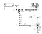
図2は、第1実施例に係るドレン処理装置のマフラ部の詳細図であり、符号9,10は、図1のものに対応している。この実施例では、ドレン処理用配管11として、フルトンチューブ11aとナイロンチューブ11bを接続して用いている。マフラ入口管10側に、金属製で耐圧耐熱性のフルトンチューブ11aを用いるのは、マフラ9及びマフラ入口管10は高温になって、内部の圧力が高くなるためである。そのフルトンチューブ11aの取付は、エンジンコンプレッサのエンジン室とマフラ室とを仕切るフロントフレーム仕切板31に、エンジン室とマフラ室とを連通する穴を設け、その穴にグロメット31aを嵌め込んで、それにフルトンチューブ11aを通し、フロントフレーム仕切板31のエンジン室側の横板部に、パイプクランパ32で固定することにより行っている。パイプクランパ32は、取付用の長穴を設けた鋼板の先端をくの字形に曲げ、そのくの字形部分でフルトンチューブ11aを支持するようにしている。
FIG. 2 is a detailed view of the muffler portion of the drain processing apparatus according to the first embodiment, and
一方、マフラ9にエンジン排気ガスを送り込むマフラ入口管10にボス10aを設け、そこにエルボコネクタ10bを取り付け、それにフルトンチューブ11a側のコネクタ11cを接続する。フルトンチューブ11aとナイロンチューブ11bの接続は、フルトンチューブ11aのエンジン室側端部のコネクタ11d,ストレートコネクタ11e,ソケット11f,ナイロンチューブ11bの端部に取り付けたハーフユニオン11gとで行う。なお、機内を取り回すナイロンチューブ11bは、たるみ,折れ,潰れがないように機内の数個所でクランプする。また、マフラ入口管10には、ガスケット30aを介してエキゾーストパイプ30が接続される。
On the other hand, a
図3は、第1実施例に係るドレン処理装置のドレン排出部の分解図であり、符号5,6,7,8は、図1のものに対応している。アフタクーラ5は、オイルセパレータ4(図1参照)に接続され、アフタクーラ5の排出口には、エルボコネクタ5a,6aを介してドレンセパレータ6が接続される。そして、ドレンセパレータ6の下流側には、エルボコネクタ6b,吐出ホース33,エルボコネクタ7aを介して保圧弁7が接続され、さらに、負荷機器に圧縮空気を供給するサービスバルブ8が接続され、さらに、オスメスエルボ7
bで分岐している。
FIG. 3 is an exploded view of the drain discharge portion of the drain treatment apparatus according to the first embodiment, and
It branches at b.
ドレンセパレータ6のドレン排出口には、ニップル6c,オスメスソケット6d,フィルタ12,ソケットニップル6e,ソケット6f,エルボユニオン36aを介してナイロンチューブ36が接続され、その他端には、ハーフユニオン36bにより、三方弁35の入口ポート35aが接続されている。さらに、三方弁35の第1の出口ポート35bには、エルボユニオン11hを介して、ドレン処理用配管11のナイロンチューブ11bが接続される。
A
なお、図2のA点と、図3のA点は、同じ位置を示しており、図2のナイロンチューブ11bと、各図のナイロンチューブ11bとが同じものであることを示している。また、ソケットニップル6eの中には、圧縮空気を無駄に出さないようにしながらドレンを排出させるためのオリフィスが設けられており、フィルタ12は、ゴミを捕集して、オリフィスにゴミが詰まらないようにするためのものであり、オスメスソケット6dとソケットニップル6eの中に収納されている。
The points A in FIG. 2 and the points A in FIG. 3 indicate the same positions, indicating that the
一方、三方弁35の第2の出口ポート35cは、ニップル35dを介してエンジンコンプレッサのベース壁37に設けたドレンボス38に直接接続される。なお、この実施例では、ドレンボス38の開口部は、Oリング38b,ドレンボルト38aで封止するようにしているが、ドレンボス38と三方弁35の切替ノブが近い位置にある場合には、受け容器でドレンボス38から排出されるドレンを受けながら三方弁35の切替ノブを操作できるので、Oリング38bとドレンボルト38aはなくてもよい。On the other hand, the
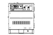
この実施例におけるエンジンコンプレッサ内のドレン配管は、図4に示すようになり、符号は、図1〜図3のものに対応している。また、エンジンコンプレッサの操作面は、図5に示すようになって、エンジンコンプレッサの操作面下部のベース壁37にドレンボス38の開口部が配置される。
Drain pipe in the engine compressor in this embodiment, Ri Na as shown in FIG. 4, numerals that correspond to those of FIGS. Further, as shown in FIG. 5, the operation surface of the engine compressor is such that the opening of the
そして、外気温が5℃以下の寒冷時に運転を行った場合、運転停止後に三方弁35を、ドレン処理用配管11側からドレンボス38側に切り替えることにより、ドレンセパレータ6やその下流配管内の水分をベース壁37に設けたドレンボス38の開口部から排出し、水抜きすることで、凍結が防止できる。その際、三方弁35の第2の出口ポート35c及びドレンボス38は、ドレンセパレータ6のドレン排出口より低い位置にあるので、三方弁35をドレン排出側に切り替えれば、ドレンは自重によりドレンボス38側に流れ、容易に排出される。
When the operation is performed when the outside air temperature is 5 ° C. or lower, the three-
このようにドレンセパレータ6とドレン処理用配管11との間に三方弁35を配設することにより、寒冷時、運転停止後に、ドレンセパレータ6やその下流配管内の水分を水抜きすることで凍結が防止できるが、その際、ドレン処理用配管11側とドレンボス38側との間は三方弁35により閉じられているので、ドレンボス38側から万が一水が浸入してきた場合、ドレンボルトがなくても、ドレン処理用配管11側への逆流を防ぐことができる。また、配管路の切り替えに三方弁35を用いれば、三方弁35は、切替え用のノブが一体になっているので、組み立てがし易く、部品点数も少なくできる。
By arranging the three-
以上、説明したように、この実施例によれば、コンプレッサの運転中、ドレンはマフラ9内で処理されるので、一時的にドレンを受けるためのドレンタンクは不要になる。また、ドレンセパレータ6の排出口から吐出される圧縮空気による騒音も、マフラ9内で吸収されるので消音器も不要になる。さらに、ドレンセパレータ6からマフラ9までのドレン排出経路中に三方弁35を配設し、三方弁35の第1の出口ポート35bをマフラ9と連結し、三方弁35の第2の出口ポート35cを外部排出口へ連結したので、寒冷時、運転
停止後に、三方弁を外部排出口側に切り替えることにより、ドレンセパレータ6やその下流配管内の水抜きができ、凍結を防止できる。
As described above, according to this embodiment, since the drain is processed in the muffler 9 during the operation of the compressor, the drain tank for temporarily receiving the drain becomes unnecessary. Further, the noise generated by the compressed air discharged from the discharge port of the
By switching the three-way valve to the external discharge port side after stopping, water can be drained from the
図6は、第2実施例に係るドレン処理装置のドレン排出部の分解図である。符号は、図3のものに対応しており、A点は、図2のA点と同じ位置を示している。図3のものと比べて、ドレンセパレータ6のドレン排出口に、ニップル6c,オスメスソケット6d,フィルタ12,ソケットニップル6eを介して、三方弁35の入口ポート35aを直接接続し、三方弁35の第2の出口ポート35cには、エルボユニオン36aを介してナイロンチューブ36を接続し、その他端を、エルボユニオン36aにより、エンジンコンプレッサのベース壁37に設けたドレンボス38に接続している点で異なっている。
FIG. 6 is an exploded view of a drain discharge portion of the drain treatment apparatus according to the second embodiment. The reference numerals correspond to those in FIG. 3 , and the point A indicates the same position as the point A in FIG . Compared with that of FIG. 3 , the inlet port 35a of the three-
この実施例におけるエンジンコンプレッサ内のドレン配管は、図7に示すようになる。そして、この実施例でも、外気温が5℃以下の寒冷時に運転を行った場合、運転停止後に三方弁35を、ドレン処理用配管11側からドレンボス38側に切り替えることにより、ドレンセパレータ6やその下流配管内の水分をベース壁37に設けたドレンボス38の開口部から排出し、水抜きすることで、凍結が防止できる。その際、三方弁35の第2の出口ポート35c及びドレンボス38は、ドレンセパレータ6のドレン排出口より低い位置にあるので、三方弁35をドレン排出側に切り替えれば、ドレンは自重によりドレンボス38側に流れ、容易に排出される。しかも、ドレンセパレータ6のドレン排出口に直接接続するようにしたので、ドレンセパレータ6と三方弁35とが一体化され、アフタクーラ5への取付が容易になる。
Drain pipe in the engine compressor in this embodiment is as shown in FIG. Further, also in this embodiment, when the operation is performed when the outside air temperature is 5 ° C. or lower, the three-
1 エンジン
2 コンプレッサ本体
3 レシーバタンク
4 オイルセパレータ
5 アフタクーラ
6 ドレンセパレータ
7 保圧弁
8 サービスバルブ
9 マフラ
10 マフラ入口管
11 ドレン処理用配管
1
Claims (3)
サのドレン処理装置であって、
前記ドレンセパレータから前記マフラまでのドレン排出経路中に三方弁を配設し、該三方弁の一つのポートを入口ポートとし、該入口ポートを前記ドレンセパレータのドレン排出口と連結し、前記三方弁の残りのポートの内の一方を第1の出口ポートとし、該第1の出口ポートを前記マフラと連結し、前記三方弁の残りの一つのポートを第2の出口ポートとし、該第2の出口ポートを外部排出口へ連結したことを特徴とするエンジンコンプレッサのドレン処理装置。 The engine and the compressor body driven by the engine are housed inside a metal housing, and the air compressed by the compressor body is stored in the engine compressor in which the housing is installed on the base. A receiver tank, an oil separator provided on the downstream side of the receiver tank to separate the oil component of the compressed air discharged from the receiver tank, an aftercooler for cooling the compressed air from the oil separator, and cooling by the aftercooler. It is provided with a drain separator that removes the condensed water and the remaining oil as a drain, the drain removed by the drain separator is allowed to flow into the muffler of the engine, and the drain is treated by the exhaust heat of the engine. It is a drain processing device of the engine compressor that has been made to do so.
A three-way valve is arranged in the drain discharge path from the drain separator to the muffler, one port of the three-way valve is used as an inlet port, the inlet port is connected to the drain discharge port of the drain separator, and the three-way valve is connected. One of the remaining ports of the three-way valve is used as a first outlet port, the first outlet port is connected to the muffler, and the remaining one port of the three-way valve is used as a second outlet port. A drain treatment device for an engine compressor, characterized in that an outlet port is connected to an external outlet.
Priority Applications (1)
| Application Number | Priority Date | Filing Date | Title |
|---|---|---|---|
| JP2018235984A JP6957121B2 (en) | 2018-12-18 | 2018-12-18 | Drain processing device for engine compressor |
Applications Claiming Priority (1)
| Application Number | Priority Date | Filing Date | Title |
|---|---|---|---|
| JP2018235984A JP6957121B2 (en) | 2018-12-18 | 2018-12-18 | Drain processing device for engine compressor |
Publications (3)
| Publication Number | Publication Date |
|---|---|
| JP2020097902A JP2020097902A (en) | 2020-06-25 |
| JP2020097902A5 JP2020097902A5 (en) | 2020-08-20 |
| JP6957121B2 true JP6957121B2 (en) | 2021-11-02 |
Family
ID=71106068
Family Applications (1)
| Application Number | Title | Priority Date | Filing Date |
|---|---|---|---|
| JP2018235984A Active JP6957121B2 (en) | 2018-12-18 | 2018-12-18 | Drain processing device for engine compressor |
Country Status (1)
| Country | Link |
|---|---|
| JP (1) | JP6957121B2 (en) |
Families Citing this family (5)
| Publication number | Priority date | Publication date | Assignee | Title |
|---|---|---|---|---|
| US11421791B2 (en) | 2020-11-24 | 2022-08-23 | Nibco Inc. | Tee union ball drain valve |
| US11359729B1 (en) | 2020-12-18 | 2022-06-14 | Nibco Inc. | 3-way T-flow ball drain valve |
| US11725747B1 (en) | 2022-07-11 | 2023-08-15 | Nibco Inc. | Water arrestor valve assembly |
| US11913569B1 (en) | 2022-09-27 | 2024-02-27 | Nibco Inc. | Serviceable ball check valve |
| US12203566B2 (en) | 2022-11-14 | 2025-01-21 | Nibco Inc. | Isolation service valve assembly for motorized zone valves |
-
2018
- 2018-12-18 JP JP2018235984A patent/JP6957121B2/en active Active
Also Published As
| Publication number | Publication date |
|---|---|
| JP2020097902A (en) | 2020-06-25 |
Similar Documents
| Publication | Publication Date | Title |
|---|---|---|
| JP6957121B2 (en) | Drain processing device for engine compressor | |
| US10655315B2 (en) | Flood water removal system | |
| JP2020097902A5 (en) | ||
| JP2016156359A (en) | Oil strainer | |
| CN219299486U (en) | Piston type air compressor cylinder cooler | |
| KR20170133066A (en) | Equipped with an anti-icing device for maritime gas turbine intake system | |
| JP2004019443A (en) | Drain discharge device | |
| JPH07174073A (en) | Package type air compressor | |
| WO2011017708A1 (en) | Dry run porting system | |
| JP2966625B2 (en) | Air supply device | |
| JP2009185678A (en) | air compressor | |
| JP7103928B2 (en) | Blow-by gas recirculation device | |
| JP2006336629A (en) | Work machine driven by engine | |
| CN104350210A (en) | Work machine | |
| JP2758544B2 (en) | Cooling water recirculation device for pump with engine | |
| JPH11193782A (en) | Water cooling type cooling method for compressed air and water cooling type aftercooling unit | |
| JP2007100511A (en) | Drain discharge part structure of compressor | |
| JP2602100Y2 (en) | Automatic aftercooler draining device for compressor | |
| JP7343580B2 (en) | Blow-by gas recirculation device | |
| CN216703402U (en) | Air compressor machine condensing equipment is used in corrugated paper production | |
| JPH11281200A (en) | Outdoor machine unit and air conditioner | |
| JP2014020279A (en) | Blow-by gas recirculation device | |
| JP6489813B2 (en) | Aftercooler drain recovery unit in the compressor | |
| JP3771205B2 (en) | Aftercool drain drain discharge method and piping structure of the after cool drain drain in the compressor | |
| JP2023104802A (en) | Oil cooling type compressor and operating method for the same |
Legal Events
| Date | Code | Title | Description |
|---|---|---|---|
| A521 | Request for written amendment filed |
Free format text: JAPANESE INTERMEDIATE CODE: A523 Effective date: 20200707 |
|
| A621 | Written request for application examination |
Free format text: JAPANESE INTERMEDIATE CODE: A621 Effective date: 20200707 |
|
| A977 | Report on retrieval |
Free format text: JAPANESE INTERMEDIATE CODE: A971007 Effective date: 20210527 |
|
| A131 | Notification of reasons for refusal |
Free format text: JAPANESE INTERMEDIATE CODE: A131 Effective date: 20210608 |
|
| A521 | Request for written amendment filed |
Free format text: JAPANESE INTERMEDIATE CODE: A523 Effective date: 20210629 |
|
| TRDD | Decision of grant or rejection written | ||
| A01 | Written decision to grant a patent or to grant a registration (utility model) |
Free format text: JAPANESE INTERMEDIATE CODE: A01 Effective date: 20211005 |
|
| A61 | First payment of annual fees (during grant procedure) |
Free format text: JAPANESE INTERMEDIATE CODE: A61 Effective date: 20211005 |
|
| R150 | Certificate of patent or registration of utility model |
Ref document number: 6957121 Country of ref document: JP Free format text: JAPANESE INTERMEDIATE CODE: R150 |
|
| R250 | Receipt of annual fees |
Free format text: JAPANESE INTERMEDIATE CODE: R250 |