JP6957119B2 - Pachinko machine - Google Patents
Pachinko machine Download PDFInfo
- Publication number
- JP6957119B2 JP6957119B2 JP2018159739A JP2018159739A JP6957119B2 JP 6957119 B2 JP6957119 B2 JP 6957119B2 JP 2018159739 A JP2018159739 A JP 2018159739A JP 2018159739 A JP2018159739 A JP 2018159739A JP 6957119 B2 JP6957119 B2 JP 6957119B2
- Authority
- JP
- Japan
- Prior art keywords
- game
- unit
- effect
- peripheral control
- ball
- Prior art date
- Legal status (The legal status is an assumption and is not a legal conclusion. Google has not performed a legal analysis and makes no representation as to the accuracy of the status listed.)
- Active
Links
Images


Description
本発明は、ぱちんこ遊技機(一般的に「パチンコ機」とも称する)や回胴式遊技機(一般的に「パチスロ機」とも称する)等の遊技機に関するものである。 The present invention relates to a gaming machine such as a pachinko gaming machine (generally also referred to as a “pachinko machine”) or a rotating drum type gaming machine (generally also referred to as a “pachislot machine”).
従来、始動入賞に基づいて画像を表示可能な表示器に複数の図柄を変動表示させ、図柄の停止結果が所定の態様となった場合に所定の遊技価値を付与する遊技機が知られている。このような遊技機において、近年では演出音の音量を遊技者が調節できるようになっている(例えば、特許文献1参照)。
Conventionally, there is known a gaming machine in which a plurality of symbols are variably displayed on a display capable of displaying an image based on a start winning prize, and a predetermined gaming value is given when the stop result of the symbols becomes a predetermined mode. .. In such a gaming machine, in recent years, the player can adjust the volume of the effect sound (see, for example, Patent Document 1).
しかしながら、近年の遊技機では遊技中に音量調節可能であっても遊技者がその音量調節タイミングを逸しやすく、遊技者の好みの遊技を実現できず遊技興趣の低下を招くおそれがあった。However, in recent gaming machines, even if the volume can be adjusted during the game, the player tends to miss the volume adjustment timing, and the player's favorite game cannot be realized, which may lead to a decrease in the interest of the game.
この発明は、こうした実情に鑑みてなされたものであり、遊技興趣の低下を抑制可能な遊技機を提供することを目的とする。 The present invention has been made in view of such circumstances, and an object of the present invention is to provide a gaming machine capable of suppressing a decline in gaming interest.
上記した目的を達成するために、請求項1に係る発明においては、所定の始動条件の成立に基づいて抽選を行い、該抽選の結果が当りである場合に、通常遊技状態よりも遊技者に有利な特定遊技状態に制御可能な遊技機であって、
所定の演出情報を表示可能な演出表示手段と、
前記抽選の結果に基づいて前記演出表示手段を表示制御して変動演出を実行する表示制御手段と、
前記演出表示手段に表示される前記変動演出に関連して音出力手段から所定の演出音を出力させる制御を行う音出力制御手段と、
操作手段の操作に基づいて前記音出力手段から出力される演出音の音量を調節可能な音量調節手段と、を備え、
前記表示制御手段は、前記所定の演出情報として特定の演出情報を前記変動演出中の特定期間に亘って表示させることが可能であり、
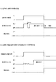
前記特定期間では前記演出音の音量が抑制され、該特定期間において、前記音量調節手段は、前記演出音の音量が抑制されている中で前記操作手段の操作を受け付けて前記演出音の音量を調節可能とするものの該調節された音量の前記演出音を前記特定期間の経過後に聴取可能とし、
前記特定期間と異なり前記変動演出中の前記演出音の音量が抑制されない非特定期間において、前記音量調節手段は、前記演出音の音量が抑制されていない中で前記操作手段の操作を受け付けて前記演出音の音量を調節可能とするとともに該調節された音量の前記演出音を当該調節タイミングで聴取可能とし、
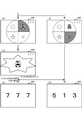
前記特定期間では、前記演出表示手段に表示されるキャラクタの数が前記特定期間とされる前のときに比べて抑制される
ことを特徴とする。
In order to achieve the above-mentioned object, in the invention according to
A production display means capable of displaying predetermined production information and
A display control means that controls the display of the effect display means based on the result of the lottery to execute a variable effect, and a display control means.
A sound output control means that controls the output of a predetermined effect sound from the sound output means in relation to the variation effect displayed on the effect display means.
It is provided with a volume adjusting means capable of adjusting the volume of the effect sound output from the sound output means based on the operation of the operating means.
The display control means can display specific effect information as the predetermined effect information over a specific period during the variable effect.
In the specific period, the volume of the effect sound is suppressed, and in the specific period, the volume adjusting means accepts the operation of the operation means while the volume of the effect sound is suppressed, and adjusts the volume of the effect sound. Although it is adjustable, the effect sound of the adjusted volume can be heard after the lapse of the specific period.
Unlike the specific period, in the non-specific period during which the volume of the effect sound during the variable effect is not suppressed, the volume adjusting means accepts the operation of the operation means while the volume of the effect sound is not suppressed. The volume of the effect sound can be adjusted, and the effect sound of the adjusted volume can be heard at the adjustment timing.
The specific period is characterized in that the number of characters displayed on the effect display means is suppressed as compared with the case before the specific period.
この発明によれば、遊技興趣の低下を抑制可能である。 According to the present invention, it is possible to suppress a decrease in the interest in the game.
[1.パチンコ遊技機の全体構成]
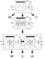
以下、本発明の遊技機としてのパチンコ遊技機について図面を参照して説明する。まず、図1〜図3を参照して実施形態に係るパチンコ遊技機の全体について説明する。図1は実施形態に係るパチンコ遊技機の外枠に対して本体枠を開放し、本体枠に対して扉枠を開放した状態を示す斜視図であり、図2はパチンコ遊技機の正面図であり、図3はパチンコ遊技機の背面図である。
[1. Overall configuration of pachinko game machines]
Hereinafter, the pachinko gaming machine as the gaming machine of the present invention will be described with reference to the drawings. First, the entire pachinko gaming machine according to the embodiment will be described with reference to FIGS. 1 to 3. FIG. 1 is a perspective view showing a state in which the main body frame is opened with respect to the outer frame of the pachinko gaming machine according to the embodiment and the door frame is opened with respect to the main body frame, and FIG. 2 is a front view of the pachinko gaming machine. Yes, FIG. 3 is a rear view of the pachinko gaming machine.
パチンコ遊技機1は、図1〜図3に示すように、遊技ホールの島設備(図示しない)に設置される外枠2と、外枠2に開閉自在に軸支され前側が開放された箱枠状の本体枠3と、本体枠3に前側から装着固定され遊技媒体としての遊技球が打ち込まれる遊技領域1100を有した遊技盤4と、本体枠3及び遊技盤4の前面を遊技者側から閉鎖するように本体枠3に対して開閉自在に軸支された扉枠5とを備えている。このパチンコ遊技機1の扉枠5には、遊技盤4の遊技領域1100が遊技者側から視認可能となるように形成された遊技窓101と、遊技窓101の下方に配置され遊技球を貯留する皿状の上皿301及び下皿302(図7を参照)と、上皿301に貯留された遊技球を遊技盤4の遊技領域1100内へ打ち込むために遊技者が操作するハンドル装置500と、を備えている。
As shown in FIGS. 1 to 3, the
また、パチンコ遊技機1は、正面視において、外枠2、本体枠3、及び扉枠5がそれぞれ上下方向へ延びた縦長の矩形状に形成されており、それぞれの左右方向の横幅が略同じ寸法とされているとともに、上下方向の縦幅の寸法が、外枠2に対して本体枠3及び扉枠5の寸法が若干短く形成されている。そして、本体枠3及び扉枠5よりも下側の位置において、外枠2の前面に装飾カバー23が取り付けられており、扉枠5及び装飾カバー23によって外枠2の前面が完全に閉鎖されるようになっている。また、外枠2、本体枠3、及び扉枠5は、上端が略揃うようにそれぞれが配置されるとともに、外枠2の左端前側の位置で本体枠3及び扉枠5が回転可能に軸支されており、外枠2に対して本体枠3及び扉枠5の右端が前側へ移動することで開状態となるようになっている。
Further, in the
また、パチンコ遊技機1は、正面視において、略円形状の遊技窓101を介して遊技球が打ち込まれる遊技領域1100が臨むようになっており、その遊技窓101の下側に前方へ突出するように二つの上皿301及び下皿302が上下に配置されている。また、扉枠5の前面右下隅部には、遊技者が操作するためのハンドル装置500が配置されており、上皿301内に遊技球が貯留されている状態で遊技者がハンドル装置500を回転操作すると、その回転角度に応じた打球強さで上皿301内の遊技球が遊技盤4の遊技領域1100内へ打ち込まれて、遊技をすることができるようになっている。
Further, in the
扉枠5の遊技窓101は、透明なガラスユニット590によって閉鎖されており、遊技者から遊技領域1100内を視認することができるものの、遊技者が遊技領域1100内へ手等を挿入して遊技領域1100内の遊技球や障害釘、各種入賞口や役物等に触ることができないようになっている。
The
[2.外枠の全体構成]
次に、遊技ホールの島設備に設置される外枠2について、図4を参照して説明する。図4は外枠の正面斜視図である。外枠2は、図4に示すように、横方向へ延びる上下の上枠板10及び下枠板11と、縦(上下)方向へ延びる左右の側枠板12,13と、それぞれの枠板10,11,12,13の端部を連結する四つの連結部材14と、を備えており、連結部材14で各枠板10,11,12,13同士を連結することで縦長の矩形状(方形状)に組立てられている。外枠2における上枠板10及び下枠板11は、所定厚さの無垢材(例えば、木材、合板、等)により形成されている。なお、上枠板10における左側端部の上面及び前面には、後述する上支持金具20が取り付けられている。
[2. Overall composition of the outer frame]
Next, the
一方、側枠板12,13は、一定断面形状の軽量金属型材(例えば、アルミ合金)とされている。なお、側枠板12,13の外側側面及び内側側面には、上下方向へ延びた複数の溝が形成されており、パチンコ遊技機1を遊技ホールのパチンコ島設備に設置する際等に、作業者の指掛りとなってパチンコ遊技機1を保持し易くすることができるようになっているとともに、外観の意匠性を高められるようになっている。
On the other hand, the
外枠2は、上枠板10の左端上面に固定される上支持金具20と、上支持金具20と対向するように配置され左側の側枠板12における下部内側の所定位置に固定される下支持金具21と、下支持金具21の下面を支持するように配置され左右の側枠板12,13を連結するように固定される補強金具22と、補強金具22の前面に固定される装飾カバー23と、を備えている。上支持金具20及び下支持金具21は、本体枠3及び扉枠5を開閉可能に軸支するためのものである。上支持金具20における支持鉤穴20cには、後述する本体枠3における上軸支金具630の軸支ピン633(図5を参照)が着脱自在に係合されるようになっている。下支持金具21における支持突起21dには、後述する本体枠3の本体枠軸支金具644に形成された本体枠軸支が挿入されるようになっており、下支持金具21の支持突起21dを、本体枠3における本体枠軸支金具644の支持穴に挿入した後に、本体枠3の上軸支金具630の軸支ピン633を支持鉤穴20cに係止することにより簡単に本体枠3を開閉自在に軸支することができるようになっている。
The
また、外枠2は、右側の側枠板13の内側に、上下方向に所定距離離反して配置される二つの閉鎖板24,25(図1を参照)が取り付け固定されている。これら閉鎖板24,25は、平面視で略L字状に形成されている。この閉鎖板24,25は、外枠2に対して本体枠3を閉じる際に、本体枠3の開放側辺に沿って取り付けられる錠装置1000(施錠装置)のフック部1054,1065(図1を参照)と係合するものであり、詳細は後述するが、錠装置1000のシリンダ錠1010に鍵を差し込んで一方に回動することにより、フック部1054,1065と閉鎖板24,25との係合が外れて外枠2に対する本体枠3の閉鎖状態を解除することができるものである。
Further, the
[3.本体枠の全体構成]
次に、外枠2の前面側に開閉自在に設けられる本体枠3について、図5及び図6を参照して説明する。図5は本体枠の正面斜視図であり、図6は本体枠における基板ユニットの背面斜視図である。本体枠3は、図5に示すように、本体枠3の骨格を形成するとともに前後方向に貫通し遊技盤4を保持するための矩形状の遊技盤保持口601を有した本体枠ベース600と、本体枠ベース600の正面視左側端部の上端及び下端にそれぞれ取り付けられ外枠2に軸支されるとともに扉枠5を軸支するための上軸支金具630及び下軸支金具640と、本体枠ベース600の下部前面に取り付けられ遊技盤4の遊技領域1100内へ遊技球を打ち込むための打球発射装置650と、本体枠ベース600の後側に取り付けられ皿ユニット300の上皿301へ遊技球を払い出すための賞球ユニット700と、本体枠ベース600の前面に取り付けられ本体枠3に対して扉枠5が開いた時に賞球ユニット700から扉枠5の皿ユニット300への遊技球の流れを遮断する球出口開閉ユニット790と、を備えている。
[3. Overall configuration of the main body frame]
Next, the
また、本体枠3は、本体枠ベース600の下部後面に取り付けられ遊技盤4を除く扉枠5や本体枠3に備えられた電気的部品を制御するための各種の制御基板や電源基板851等を一纏めにしてユニット化した基板ユニット800と、本体枠ベース600における遊技盤保持口601の後側開口を覆う裏カバー900と、本体枠ベース600の正面視左側端部を被覆する側面防犯板950と、本体枠ベースの正面視右側端部に取り付けられ外枠2に対する本体枠3の開閉施錠、及び本体枠3に対する扉枠5の開閉施錠をする錠装置1000と、を主に備えている。
Further, the
[3−1.本体枠ベース]
次に、本体枠ベース600について説明する。本体枠ベース600は、合成樹脂によって一体成形されており、正面視の外形が扉枠5の外形と沿った縦長の矩形状とされているとともに、前後方向に所定量の奥行きを有するように形成されている。本体枠ベース600は、上部から下部へ向かって全体の約3/4の範囲内が前後方向へ矩形状に貫通し遊技盤4の外周を嵌合保持可能な遊技盤保持口601と、本体枠ベース600の正面視左辺を除く前端外周を形成するコ字状の前端枠部602と、前端枠部602の前面から後方へ向かって窪み、扉枠5における扉枠ベース本体110の下端から後方へ突出した扉枠突片110c(図1を参照)、扉枠5の補強ユニット150における上側補強板金151の後方へ突出した上側の屈曲突片167(図1を参照)及び開放側補強板金153の後方へ突出した開放側外折曲突片164(図1を参照)が挿入係合される係合溝603と、を備えている。
[3-1. Body frame base]
Next, the main
また、本体枠ベース600は、遊技盤保持口601の下側から本体枠ベース600下端まで延出し前端枠部602の前端から所定量後側へ窪み左右方向へ板状に広がった下部後壁部604と、前端枠部602よりも内側で後方へ突出し遊技盤保持口601の内周壁を形成する周壁部605と、を備えている。周壁部605によって、コ字状の前端枠部602の自由端部(正面視で上下の左側端部)同士が連結されるようになっており、本体枠ベース600の外形が枠状となるようになっている。
Further, the main
また、本体枠ベース600は、下部後壁部604の上端に遊技盤保持口601の下辺を形成すると共に遊技盤4が載置される遊技盤載置部606と、遊技盤載置部606の左右方向略中央から上方へ突出し遊技盤4における遊技パネル1150のアウト球排出溝と係合する位置決め突起607と、周壁部605における正面視右側内壁の所定位置に形成され遊技盤4の遊技盤止め具1120が止め付けられる遊技盤係止部と、周壁部605の上側内壁から下方へ垂下し下端が遊技盤4の上端と当接可能な板状で左右方向に複数配置された上端規制リブ609と、を備えている。本体枠ベース600の位置決め突起607は、遊技盤4のアウト球排出溝と嵌合することで、遊技盤4の下端が左右方向及び後方向へ移動するのを規制することができるようになっている。また、遊技盤係止部は、遊技盤4の遊技盤止め具1120が係止されることで遊技盤4の正面視右辺が前後方向へ移動するのを規制することができるようになっている。なお、遊技盤4の正面視左辺は、詳細は後述するが、側面防犯板950の位置決め部材956によって前後方向への移動が規制されるようになっている。
Further, the main
また、本体枠ベース600は、下部後壁部604が前端枠部602の前面よりも後側へ一段窪んだ位置に形成されており、下部後壁部604の正面視右側前面に、打球発射装置650の発射ソレノイド654がソレノイド収容凹部内に収容されるように前側から打球発射装置650が取り付けられるようになっている。この下部後壁部604の前面に打球発射装置650を取り付けた状態では、打球発射装置650における発射レール660の上端よりも正面視左側に、左方向及び下方へ広がったファール空間626が形成されるようになっている。本実施形態では、本体枠3に対して扉枠5を閉じた状態とすると、ファール空間626の下部にファールカバーユニット540におけるファール球入口542e(図1を参照)が位置するようになっており、ファール空間626を下降した遊技球が、ファールカバーユニット540のファール球入口542eに受けられて、皿ユニット300における下皿302(図7を参照)へ排出されるようになっている。
Further, the main
また、本体枠ベース600は、正面視で下部後壁部604の左右中央よりも左側に前後方向へ矩形状に貫通する開口部と、開口部の上側及び正面視左右両側に複数形成され前後方向に貫通した透孔615と、を備えている。この本体枠ベース600の開口部は、前側から中継端子板カバー692によって閉鎖されるようになっており、中継端子板カバー692の開口692aを通して、下部後壁部604の後面に取り付けられた基板ユニット800の主扉中継端子板880と周辺扉中継端子板882とが前側へ臨むようになっている。
Further, the main
また、本体枠ベース600は、正面視で下部後壁部604の右端上部に前後方向に貫通した略円形のシリンダ錠貫通穴611の下側前面に、本体枠3に対する扉枠5の開放を検出するための扉枠開放スイッチ618が取り付けられており、本体枠3に対して扉枠5が開かれる(開放される)と、その押圧が解除されて扉枠5の開放を検出することができるようになっている。また、本体枠ベース600は、扉枠開放スイッチ618が取り付けられた位置よりも下側後面に、外枠2に対する本体枠3の開放を検出するための本体枠開放スイッチ619が取り付けられており、外枠2に対して本体枠3が開かれる(開放される)と、その押圧が解除されて本体枠3の開放を検出することができるようになっている。
Further, the main
[3−2.上軸支金具及び下軸支金具]
次に、上軸支金具630及び下軸支金具640について説明する。上軸支金具630及び下軸支金具640は、本体枠ベース600の正面視左端上下後面の金具取付部に、所定のビスを用いてそれぞれ取り付けることで、本体枠3に対して扉枠5を開閉可能に軸支することができるとともに、外枠2に対して本体枠3を開閉可能に軸支させることができるものである。
[3-2. Upper shaft support and lower shaft support]
Next, the upper shaft
上軸支金具630は、本体枠ベース600の上側の金具取付部に取り付けられ上下左右方向へ広がる板状の取付部631と、取付部631の上端から前方へ延出する板状の前方延出部632と、前方延出部632の前端付近から上方へ延びだすように突設された軸支ピン633と、軸支ピン633の正面視左側に配置され扉枠5の軸ピン155(図7を参照)が挿入される上下方向に貫通した扉枠軸支穴634と、前方延出部632の正面視左側端部から下方へ垂下し扉枠5の開放側への回動端を規制するストッパと、を備えている。上軸支金具630は、取付部631、前方延出部632、及びストッパが、一枚の金属板を屈曲成形することで一体的に形成されている。
The upper
下軸支金具640は、扉枠5を軸支するための扉枠軸支金具642と、扉枠軸支金具642の下側に配置され外枠2に対して本体枠3を軸支するための本体枠軸支金具644と、を備えている。下軸支金具640における扉枠軸支金具642は、本体枠ベース600の下側の金具取付部に取り付けられ上下左右方向へ広がる板状の取付部と、取付部の下端から前方へ延出する板状の前方延出部642bと、前方延出部642bの前端付近に上下方向へ貫通し扉枠5の軸ピン157(図7を参照)が挿入される扉枠軸支穴642cと、前方延出部642bの正面視左側端部から上方へ立設され扉枠5の開放側への回動端を規制するストッパ642dと、を備えている。この扉枠軸支金具642は、取付部、前方延出部642b、及びストッパ642dが、一枚の金属板を屈曲成形することで一体的に形成されている。
The lower
また、下軸支金具640における本体枠軸支金具644は、本体枠ベース600の下側の金具取付部に取り付けられ上下左右方向へ広がる板状の取付部と、取付部の下端から前方へ延出する前方延出部644bと、前方延出部644b前端付近に上下方向へ貫通した本体枠軸支穴と、を備えている。本体枠軸支金具644もまた、取付部、及び前方延出部644bが、一枚の金属板を屈曲成形することで一体的に形成されている。
Further, the main body frame shaft support metal fitting 644 in the lower shaft support metal fitting 640 has a plate-shaped mounting portion that is attached to the metal fitting mounting portion on the lower side of the main
下軸支金具640は、扉枠軸支金具642の取付部と本体枠軸支金具644の取付部とが前後方向に重なった(接した)状態とされるとともに、扉枠軸支金具642の前方延出部642bと本体枠軸支金具644の前方延出部644bとが上下方向に所定距離離間した状態で、本体枠ベース600における下側の金具取付部に取り付けられるようになっている。
The lower
上軸支金具630及び下軸支金具640は、本体枠ベース600に取り付けた状態で、上軸支金具630の軸支ピン633と、下軸支金具640の本体枠軸支穴とが同軸上に位置するようになっており、下軸支金具640における本体枠軸支金具644の本体枠軸支穴が、外枠2における下支持金具21の支持突起21d(図4を参照)に嵌合挿入されるように、本体枠軸支金具644の前方延出部644bを、下支持金具21の支持突出片21c(図4を参照)上に載置した上で、上軸支金具630の軸支ピン633を、外枠2における上支持金具20の支持鉤穴20c(図4を参照)内に挿入することで、本体枠3を外枠2に対して開閉可能に軸支させることができるようになっている。
When the upper shaft
また、上軸支金具630及び下軸支金具640は、本体枠ベース600に取り付けた状態で、上軸支金具630の扉枠軸支穴634と、下軸支金具640の扉枠軸支穴642cとが同軸上に位置するようになっており、下軸支金具640における扉枠軸支金具642の扉枠軸支穴642cに、扉枠5の軸ピン157が挿入されるように扉枠5の下軸支部158(図7を参照)を扉枠軸支金具642の前方延出部642b上に載置した上で、扉枠5の軸ピン155を、上軸支金具630の扉枠軸支穴634に挿入することで、本体枠3に対して扉枠5を開閉可能に軸支することができるようになっている。なお、本実施形態では、扉枠5の上側の軸ピン155は、上下方向へ摺動可能とされており、上軸支金具630の扉枠軸支穴634へ挿入させる際に、軸ピン155を一旦、下方へスライドさせて、扉枠5の上軸支部156と上軸支金具630の前方延出部632とが上下に重なるようにした上で、軸ピン155を上方へスライドさせることで扉枠軸支穴634へ挿入することができるようになっている。
Further, the upper shaft
[3−3.打球発射装置]
次に、打球発射装置650について説明する。打球発射装置650は、本体枠ベース600における下部後壁部604の前面所定位置に取り付けられる金属板の発射ベース652と、発射ベース652の下部後面に前側へ回転駆動軸654aが突出するように取り付けられる発射ソレノイド654と、発射ソレノイド654の回転駆動軸654aに一体回転可能に固定される打球槌656と、打球槌656の先端に固定される槌先658と、槌先658の移動軌跡上における所定位置を基端として正面視斜め左上へ延出し発射ベース652の前面に取り付けられる発射レール660と、発射レール660の基端上部に発射レール660との間で打球槌656先端の槌先658が通過可能とされると同時に遊技球が通過不能な隙間を形成し発射レール660の基端に遊技球を保持する球止め片662と、球止め片662によって発射レール660の基端に保持された遊技球を打球可能な打球位置よりも打球槌656(槌先658)が発射レール660側へ回動するのを規制するストッパ664と、を備えている。
[3-3. Hit ball launcher]
Next, the hitting
この打球発射装置650における発射ソレノイド654は、詳細な図示は省略するが、回転駆動軸654aがハンドル装置500の回転操作角度に応じた強さ(速さ)で往復回動するようになっている。また、打球発射装置650の打球槌656は、発射ソレノイド654の回転駆動軸654aに固定される固定部656aと、固定部656aから緩やかな円弧状に延出し先端が回転駆動軸654aの軸心に対して法線方向を向き先端に槌先658が固定される棹部656bと、棹部656bに対して固定部656aを挟んで反対側へ延出しストッパ664と当接可能なストッパ部656cと、を備えている。打球槌656のストッパ部656cがストッパ664と当接することで、先端の槌先658が打球位置(正面視で反時計周りの方向の回動端)よりも発射レール660側へ回動するのが規制されるようになっている。
Although detailed illustration is omitted, the firing
打球発射装置650は、本体枠ベース600の下部後壁部604に取り付けた状態においては、発射レール660の上端が左右方向の略中央で下部後壁部604の上端、つまり、遊技盤載置部606(遊技盤保持口601の下辺)よりも下方に位置するようになっており、遊技盤保持口601に保持された遊技盤4における外レール1111の下端との間で、左右方向に所定幅で下方へ広がったファール空間626が形成されるようになっている。そして、打球発射装置650は、発射レール660よりも正面視左側のファール空間626を飛び越えるようにして遊技球を発射することで、遊技盤4の遊技領域1100内へ遊技球を打ち込むことができるようになっている。なお、本体枠3に対して扉枠5を閉じた状態においては、ファール空間626の下部に、扉枠5に取り付けられるファールカバーユニット540のファール球入口542eが位置するようになっており、遊技領域1100内へ打ち込まれずにファール球となった遊技球が、ファール空間626を落下してファール球入口542eへ受け入れられて、下皿302へ排出されるようになっている。
When the ball
[3−4.賞球ユニット]
次に、賞球ユニット700について説明する。パチンコ遊技機1を設置するホールにおけるパチンコ島設備において、パチンコ島設備側からパチンコ遊技機1へ供給された遊技球を貯留した上で、所定の払出指示に基づいてパチンコ遊技機1の上皿301へ払い出すものである。この賞球ユニット700は、本体枠ベース600の後面に取り付けられる賞球ベース710と、賞球ベース710の後面上部に取り付けられパチンコ島設備側から供給される遊技球を受けると共に貯留する賞球タンク720と、賞球タンク720の下側に配置され賞球タンク720に貯留された遊技球を整列させて下流側へ送るタンクレールユニット730と、タンクレールユニット730によって整列された遊技球を所定の払出指示に基づいて払い出す賞球装置740と、賞球装置740によって払出された遊技球を皿ユニットの上皿301へ誘導することができると共に上皿301が遊技球で満タンになると払出された遊技球を下皿302側へ分岐誘導することができる満タン分岐ユニット770と、を主に備えている。
[3-4. Prize ball unit]
Next, the
また、賞球ユニット700は、賞球ベース710の後面に取り付けられる外部端子板784と、外部端子板784の後側を覆う外部端子板カバー786と、を備えている。
Further, the
[3−4−1.賞球タンク]
賞球タンク720は、底壁部721の外周が外周壁部722で囲まれており、底壁部721上に所定量の遊技球を貯留することができるようになっている。また、賞球タンク720は、底壁部721の上面が、排出口723へ向かって低くなるように傾斜しており、底壁部721上の遊技球が排出口723へ向かって転動するようになっている。
[3-4-1. Prize ball tank]
In the
また、賞球タンク720は、軸部725に回動自在に軸支される二つの球ならし部材727を備えている。この球ならし部材727は、一端側が軸部725に軸支されるようになっていると共に内部に錘を保持しており、自重によって他端側が垂下するようになっている。この球ならし部材727は、後述するタンクレールユニット730内に垂下するようになっており、タンクレールユニット730内を流通する遊技球をならして整列させることができるものである。
Further, the
[3−4−2.タンクレールユニット]
タンクレールユニット730は、賞球タンク720の下側に配置され左右方向へ長く延びたタンクレール731を備えている。このタンクレール731は、上方が開放された所定深さの樋状で前後方向に遊技球が二列で整列することが可能な幅(奥行)とされ、正面視左側(軸支側)端部が低くなるように底部が傾斜している。
[3-4-2. Tank rail unit]
The
また、タンクレールユニット730は、タンクレール731の排出口上部に回転可能に支持される整列歯車732と、整列歯車732の上部を覆う歯車カバー733と、歯車カバー733の正面視右端と連続しタンクレール731の上部を閉鎖する球押え板734と、タンクレール731内に進退可能とされタンクレール731内の遊技球が排出口側へ転動するのを停止させることが可能な球止片735と、を備えている。整列歯車732は、タンクレール731の仕切壁によって二列に仕切られた遊技球の二つの流路と対応するように、前後方向に並んで二つ備えられている。
Further, the
[3−4−3.賞球装置]
賞球装置740は、タンクレールユニット730の排出口から排出供給された遊技球を、所定の払出指示に基づいて皿ユニット300の上皿301へ払い出すためのものである。賞球装置740は、上端に開口し遊技球の外形よりも若干広い幅で上下方向の中央よりもやや下側の位置まで延出する供給通路と、供給通路の下端と連通し所定広さの空間を有した振分空間と、振分空間の背面視左側(開放側)下端と連通し略く字状に曲がって背面視左側面に開口する賞球通路と、振分空間の背面視右側(軸支側)下端と連通し下方へ延出して下端に開口する球抜通路と、を備えている。この供給通路、振分空間、賞球通路、及び球抜通路は、後方へ開放された状態で形成されている。
[3-4-3. Prize ball device]
The
賞球装置740は、払出モータ744の回転軸に一体回転可能に固定されモータ支持板の後側に配置される第1ギアと、第1ギアと噛合する第2ギアと、第2ギアと噛合する第3ギアと、第3ギアとともに一体回転し振分空間内に配置される払出回転体と、払出回転体とは第3ギアを挟んで反対側に一体回転可能に固定され周方向に等間隔で複数(本実施形態では、3つ)の検出スリットが形成された回転検出盤と、を備えるとともに、供給通路内の遊技球の有無を検出するための球切れスイッチ750と、賞球通路内を流下する遊技球を検出するための計数スイッチ751と、払出回転体と一体回転する回転検出盤に形成された検出スリットを検出するための回転角スイッチ752と、回転角スイッチ752を保持する回転角スイッチ基板753と、払出モータ744、球切れスイッチ750、計数スイッチ751、及び回転角スイッチ752と後述する払出制御基板との接続を中継する賞球ケース内基板754と、を備えている。
The
払出回転体は、周方向に等間隔でそれぞれ1つの遊技球を収容可能な大きさの3つの凹部を備えており、払出回転体が回転することで、供給通路から供給された遊技球が1球ずつ凹部に収容されて、賞球通路又は球抜通路側へ払い出すことができるようになっている。また、払出回転体と一体回転する回転検出盤に形成された3つの検出スリットは、回転検出盤の外周に等分(120度ごと)に形成されるとともに、払出回転体の凹部間と対応する位置にそれぞれ設けられており、検出スリットを回転角スイッチ752によって検出することで、払出回転体の回転位置を検出することができるようになっている。なお、本実施形態では、回転検出盤(払出回転体)の各検出スリット間(120度)の回転は、払出モータ744の18ステップの回転に相当するように設計されている。
The payout rotating body is provided with three recesses having a size capable of accommodating one game ball at equal intervals in the circumferential direction, and by rotating the payout rotating body, the game ball supplied from the supply passage is one. Each ball is housed in a recess and can be paid out to the prize ball passage or the ball removal passage side. Further, the three detection slits formed in the rotation detection board that rotates integrally with the payout rotating body are formed in equal parts (every 120 degrees) on the outer circumference of the rotation detection board, and correspond to the recesses of the payout rotating body. Each position is provided, and the rotation position of the payout rotating body can be detected by detecting the detection slit with the rotation angle switch 752. In this embodiment, the rotation between the detection slits (120 degrees) of the rotation detection board (delivery rotating body) is designed to correspond to the rotation of 18 steps of the
賞球装置740は、払出モータ744によって払出回転体が背面視反時計周りの方向へ回転させられると、供給通路内の遊技球が、賞球通路へ払出されるようになっており、払出回転体の回転によって賞球通路へ払出された遊技球は、計数スイッチ751によって1球ずつ数えられた上で賞球通路へ受け渡されるようになっている。一方、球抜き操作部材がホールの店員等により操作されると、供給通路内の遊技球が球抜通路へ払出されるようになっており、球抜通路へ払出された遊技球は、球抜通路の下端から後述する満タン分岐ユニット770を介してパチンコ遊技機1の後側外部へと排出することができるようになっている。
In the
[3−4−4.満タン分岐ユニット]
満タン分岐ユニット770は、全体が後端から前端へ向かうに従って低くなるような箱状に形成されており、後端上部における左右方向の略中央に上方へ向かって開口し賞球装置740の賞球通路を流下してきた遊技球を受ける賞球受口と、賞球受口の下側に配置され左右方向へ広がった分岐空間と、分岐空間における賞球受口の直下から前側へ向かって遊技球を誘導する通常通路と、通常通路を流通した遊技球を前方へ放出し前端の正面視右端に開口した通常球出口774と、分岐空間における賞球受口の直下よりも背面視右側へ離れた位置から前側へ向かって遊技球を誘導する満タン通路と、満タン通路を流通した遊技球を前方へ放出し通常球出口774の正面視左側に開口した満タン球出口776と、を備えている。
[3-4-4. Full tank branch unit]
The full
また、満タン分岐ユニット770は、後端上部の正面視左側端部に上方へ向かって開口し賞球装置740の球抜通路を流下してきた遊技球を受ける球抜受口と、球抜受口に受けられた遊技球を前側へ誘導する球抜通路と、球抜通路を流通した遊技球を前方へ放出し正面視左端で通常球出口774及び満タン球出口776よりも後方の位置で開口した球抜出口と、を備えている。
Further, the full
満タン分岐ユニット770は、本体枠3に対して扉枠5を閉じた状態とすると、通常球出口774及び満タン球出口776が、それぞれ扉枠5におけるファールカバーユニット540の第一球入口542a及び第二球入口542c(図1を参照)と対向して連通するようになっており、通常球出口774から放出された遊技球は、ファールカバーユニット540の第一球入口542aを通って皿ユニット300の上皿301へ供給され、満タン球出口776から放出された遊技球は、ファールカバーユニット540の第二球入口542cを通って皿ユニット300の下皿302へ供給されるようになっている。また、球抜出口は、本体枠ベース600における本体枠ベース球抜通路の背面視右側上端と連通するように形成されており、球抜出口から放出された遊技球が本体枠ベース600の本体枠ベース球抜通路へ受け渡されるようになっている。
In the full
皿ユニット300の上皿301が遊技球で満タンとなった状態で、更に賞球ユニット700(賞球装置740)から遊技球が払出されると、ファールカバーユニット540の第一球出口から上皿301側へ出られなくなった遊技球が、ファールカバーユニット540の第一球通路内で滞り、やがて、満タン分岐ユニット770における通常球出口774を通して上流の通常通路内も一杯になる。この状態で、賞球受口から分岐空間内へ侵入した遊技球は、通常通路内へ侵入することができず、分岐空間内で横方向へ移動し始め、横方向へ移動した遊技球が満タン通路内へ侵入して、満タン球出口からファールカバーユニット540の第二球入口542c、第二球通路、そして第二球出口を介して皿ユニット300の下皿302へ供給されるようになっている。
When the
[3−5.基板ユニット]
次に、基板ユニット800について説明する。基板ユニット800は、図6に示すように、本体枠ベース600の下部後壁部の後面に取り付けられる基板ユニットベース810と、基板ユニットベース810の正面視左側後面に取り付けられるスピーカボックス820と、基板ユニットベース810の後面に取り付けられる電源基板ボックスホルダ840と、電源基板ボックスホルダ840の後面に取り付けられ後端がスピーカボックス820の後端と略同一面状となる大きさに形成される電源基板ボックス850と、電源基板ボックス850及びスピーカボックス820の後面に取り付けられる払出制御基板ボックス860と、払出制御基板ボックス860の正面視左側端部を覆うようにスピーカボックス820の後面に取り付けられる端子基板ボックス870と、基板ユニットベース810の前面に取り付けられる主扉中継端子板880及び周辺扉中継端子板882と、を備えている。
[3-5. Board unit]
Next, the
電源基板ボックスホルダ840は、正面視で左右中央よりも左側前面に、上方へ開放され遊技盤4のアウト球排出部から排出された下方へ排出された遊技球を受ける排出球受部841と、排出球受部841で受けられた遊技球を下方へ誘導して排出する排出通路842と、排出通路842及び排出球受部841の横(正面視で右側)の前面に前方及び上方へ開放され電源基板ボックスホルダ840の後面全体が前側へ窪んだように形成され電源基板ボックス850の前端を収容可能なボックス収容部と、を備えている。
The power supply
また、電源基板ボックスホルダ840は、排出通路842の開放された前端側が基板ユニットベース810の後面によって閉鎖されるようになっているとともに、基板ユニットベース810の開口部が排出通路842へ臨む位置に形成されており、本体枠ベース600における下部後壁部の後面に形成された本体枠ベース球抜通路を流通して基板ユニットベース810の開口部を通って基板ユニットベース810の後側へ流下した遊技球と、遊技盤4のアウト球排出部から排出されて排出球受部841で受けられた遊技球と、を排出通路842を通してパチンコ遊技機1の後側下方へ排出することができるようになっている。
Further, in the power supply
電源基板ボックス850は、前方が開放された横長の箱状に形成されており、その前端開口を閉鎖するように取り付けられた電源基板851を備えている。この電源基板ボックス850は、電源基板851に取り付けられた各種電子部品が収容されるようになっており、上面及び下面に形成された複数のスリット850aを介して、電子部品等からの熱を外部へ放出することができるようになっている。なお、電源基板ボックス850の後面には、電源基板851に取り付けられた電源スイッチ852が臨むようになっている。
The power
払出制御基板ボックス860は、横長で後方が開放された薄箱状のボックスベース861と、ボックスベース861内へ後側から嵌合し前方が開放された薄箱状のカバー862と、ボックスベース861の後面に取り付けられカバー862によって後面が覆われる払出制御基板4110と、を備えている。また、払出制御基板ボックス860は、背面視左端から外方へ突出しボックスベース861及びカバー862の双方に形成された複数の分離切断部863を備えており、複数の分離切断部863の一箇所でボックスベース861とカバー862とがカシメ固定されている。これによってボックスベース861とカバー862とを分離するためには、分離切断部863を切断しないと分離できないようになっており、払出制御基板ボックス860を開くと、その痕跡が残るようになっている。したがって、払出制御基板ボックス860が不正に開閉させられたか否かが判るようになっている。なお、本実施形態では、検査等のために払出制御基板ボックス860を一回だけ開閉することができるようになっている。
The payout
また、払出制御基板ボックス860は、払出制御基板4110に取り付けられた操作スイッチ860a(エラー解除部)、及び検査用出力端子860c等がカバー862を通して後方へ臨むようになっている。また、払出制御基板ボックス860は、主制御基板4100等と接続するための各種接続用の端子が、カバー862を通して後方へ臨むようになっている。なお、操作スイッチ860aは、電源投入時において払出制御基板4110のマイクロプロセッサに内蔵されるRAM、及び主制御基板4100のマイクロプロセッサに内蔵されるRAMをクリアする場合に操作されたり、電源投入後においてエラー報知されている際に、そのエラーを解除するために操作されたりするようになっており、電源投入時におけるRAMクリアを行う機能と、電源投入後(RAMクリアとして機能を奏する期間を経過した後)におけるエラー解除を行う機能と、を有している。この点についての詳細な説明を後述する。
Further, in the payout
端子基板ボックス870は、スピーカボックス820の後面に取り付けられる基板ベース871と、基板ベース871の後面に取り付けられ後方へ向かって周辺パネル中継端子872が固定された枠周辺中継端子板868と、基板ベース871の後面に取り付けられ後方へ向かってCRユニット中継端子873が固定された遊技球等貸出装置接続端子板869と、周辺パネル中継端子872とCRユニット中継端子873とが後側へ臨むように基板ベース871の後側を覆う基板カバー874と、を備えている。周辺パネル中継端子872は、パチンコ遊技機1を設置するパチンコ島設備側に備えられたパチンコ遊技機1の稼動状態等を表示するための度数表示器と接続するためのものであり、CRユニット中継端子873は、パチンコ遊技機1と隣接して設置されるCRユニットと接続するためのものである。
The
主扉中継端子板880及び周辺扉中継端子板882は、本体枠3に取り付けられる遊技盤4に備えられた周辺制御基板4140や基板ユニット800の払出制御基板4110等と、扉枠5に備えられたハンドル装置500、各装飾基板や操作ユニット400等との接続を中継するためのものである。これら主扉中継端子板880及び周辺扉中継端子板882は、基板ユニットベース810の前面に形成された基板取付部に取り付けることで、本体枠ベース600の前面から前側へ臨むようになっており、扉枠5から延びだした配線を接続することができるようになっている。
The main door
なお、主扉中継端子板880及び周辺扉中継端子板882は、本体枠ベース600の前面に取り付けられる中継端子板カバー692によってその前側が覆われるようになっているとともに、中継端子板カバー692の開口692aを通して、接続端子のみが前側へ臨むようになっており、本体枠3の前面がすっきりした外観となるようになっている。
The front side of the main door
また、主扉中継端子板880は、扉枠5側に配置される皿ユニット300における貸球ユニット360の貸球ボタン361、返却ボタン362、貸出残表示部363、ハンドル装置500のポテンショメータ512、タッチスイッチ516、発射停止スイッチ518、及びファールカバーユニット540の満タンスイッチ550と、本体枠3側に配置される払出制御基板4110との接続を中継するためのものである。なお、貸球ユニット360の貸球ボタン361、返却ボタン362、貸出残表示部363、ハンドル装置500のポテンショメータ512、タッチスイッチ516、発射停止スイッチ518、及びファールカバーユニット540の満タンスイッチ550についての説明を後述する。
Further, the main door
また、周辺扉中継端子板882は、扉枠5側に配置される各装飾ユニット200,240,280及び皿ユニット300や操作ユニット400に備えられた各装飾基板、及び操作ユニット400に備えられた、ダイヤル駆動モータ414、ダイヤル操作部401や押圧操作部405の操作を各々検出する各種スイッチと、本体枠3側に配置される遊技盤4の周辺制御基板4140との接続を中継するためのものである。なお、扉枠5側に配置される各装飾ユニット200,240,280及び皿ユニット300や操作ユニット400に備えられた各装飾基板、及び操作ユニット400に備えられた、ダイヤル駆動モータ414、ダイヤル操作部401や押圧操作部405の操作を検出する各種スイッチについての説明は後述する。
Further, the peripheral door
[4.扉枠の全体構成]
次に、本体枠3の前面側に開閉自在に設けられる扉枠5について、図7を参照して説明する。図7は扉枠の斜視図である。扉枠5は、図7に示すように、外形が縦長の矩形状に形成され内周形状がやや縦長の円形状(楕円形状)とされた遊技窓101を有する扉枠ベースユニット100と、扉枠ベースユニット100の前面で遊技窓101の右外周に取り付けられる右サイド装飾ユニット200と、右サイド装飾ユニット200と対向し扉枠ベースユニット100の前面で遊技窓101の左外周に取り付けられる左サイド装飾ユニット240と、扉枠ベースユニット100の前面で遊技窓101の上部外周に取り付けられる上部装飾ユニット280と、右サイド装飾ユニット200及び左サイド装飾ユニット240の下端下側に配置され扉枠ベースユニット100の前面に取り付けられる一対のサイドスピーカカバー290と、を備えている。なお、上部装飾ユニット280、右サイド装飾ユニット200及び左サイド装飾ユニット240の背部には複数のLED(LED基板)が配置し、後述する遊技盤側液晶表示装置1900にて実行される演出に関連して所定の発光態様で発光制御されて、上部装飾ユニット280、右サイド装飾ユニット200及び左サイド装飾ユニット240を発光装飾するようになっている。
[4. Overall configuration of door frame]
Next, the
また、扉枠5は、扉枠ベースユニット100の前面で遊技窓101の下部に取り付けられる皿ユニット300と、皿ユニット300の上部中央に取り付けられる操作ユニット400と、皿ユニット300の右側に取り付けられる上皿側液晶表示装置470、皿ユニット300を貫通して扉枠ベースユニット100の右下隅部に取り付けられ遊技球の打込操作をするためのハンドル装置500と、扉枠ベースユニット100を挟んで皿ユニット300の後側に配置され扉枠ベースユニット100の後面に取り付けられるファールカバーユニット540と、ファールカバーユニット540の右側で扉枠ベースユニット100の後面に取り付けられる球送ユニット580と、扉枠ベースユニット100の後側に遊技窓101を閉鎖するように取り付けられるガラスユニット590と、を備えている。
Further, the
[4−1.扉枠ベースユニット]
次に、扉枠ベースユニット100について説明する。扉枠ベースユニット100は、外形が縦長の矩形状に形成されるとともに、前後方向に貫通し内周が縦長の略楕円形状に形成された遊技窓101を有する扉枠ベース本体110と、扉枠ベース本体110の前面で遊技窓101の上部中央に取り付けられ上部装飾ユニットを固定するための上部ブラケット120と、扉枠ベース本体110の前面で遊技窓101の下端左右両外側に取り付けられる一対のサイドスピーカ130と、扉枠ベース本体110の前面で正面視右下隅部に取り付けられハンドル装置500を支持するためのハンドルブラケットと、を備えている。
[4-1. Door frame base unit]
Next, the door
また、扉枠ベースユニット100は、扉枠ベース本体110の後側に固定される金属製で枠状の補強ユニット150(図1を参照)と、扉枠ベース本体110の後面で遊技窓101の下部を被覆するように取り付けられる防犯カバー180(図1を参照)と、扉枠ベース本体110の後面で遊技窓101の外周の所定位置に回動可能に取り付けられるガラスユニット係止部材190(図1を参照)と、背面視で左右方向の中央より左側(開放側)に配置され遊技窓101の下端に沿って扉枠ベース本体110の後面に取り付けられる発射カバー191(図1を参照)と、発射カバー191の下側で扉枠ベース本体110の後面に取り付けられ後述するハンドル装置500のポテンショメータ512と後述する遊技盤4に備えられた主制御基板4100との接続を中継するハンドル中継端子板192(図1を参照)と、ハンドル中継端子板192の後側を被覆するハンドル中継端子板カバー193(図1を参照)と、左右方向の中央を挟んで発射カバー191やハンドル中継端子板192等とは反対側(背面視で左右方向中央よりも右側(軸支側))に配置され扉枠ベース本体の後面に取り付けられる枠装飾駆動アンプ基板194(図1を参照)と、枠装飾駆動アンプ基板194の後側を被覆する枠装飾駆動アンプ基板カバー195(図1を参照)と、を備えている。
Further, the door
枠装飾駆動アンプ基板194は、サイドスピーカ130や左右のサイド装飾ユニット200,240の上部スピーカと電気的に接続されるとともに、後述する遊技盤4に備えられた周辺制御基板4140と電気的に接続されており、周辺制御基板4140から送られた音響信号を増幅して各スピーカ130へ出力する増幅回路を備えている。なお、具体的な図示は省略するが、本実施形態では、各装飾ユニット200,240,280及び皿ユニット300や操作ユニット400に備えられた各装飾基板、操作ユニット400に備えられたダイヤル駆動モータやスイッチ、ハンドル中継端子板192、皿ユニット300の貸球ユニット360等と、払出制御基板4110や周辺制御基板4140等とを電気的に接続する配線が、枠装飾駆動アンプ基板194の背面視で右側(軸支側)の位置に集約して束ねられた上で後方へ延出して本体枠3の主扉中継端子板880や周辺扉中継端子板882に接続されるようになっている。
The frame decoration
[4−1−1.扉枠ベース本体]
扉枠ベース本体110は、合成樹脂によって縦長の額縁状に形成されており、前後方向に貫通し内形が縦長で略楕円形状の遊技窓101が全体的に上方へオフセットするような形態で形成されている。この遊技窓101は、左右側及び上側の内周縁が連続した滑らかな曲線状に形成されているのに対して、下側の内周縁は左右へ延びた直線状に形成されている。また、扉枠ベース本体110における遊技窓101の下側の内周縁には、軸支側(正面視で左側)にファールカバーユニット540の第一球出口を挿通可能な方形状の切欠部が形成され、遊技窓101の下辺の左右両外側に配置されサイドスピーカ130を取り付けて固定するためのスピーカ取付部、正面視で右下隅部に配置され前方へ膨出した前面の右側(開放側)端が後退するように斜めに傾斜しハンドルブラケットを取り付けるためのハンドル取付部、ハンドル取付部の所定位置で前後方向へ貫通しハンドル装置500からの配線が通過可能な配線通過口、ハンドル取付部の上側で前方へ向かって短く延びた筒状に形成され後述するシリンダ錠1010が挿通可能な錠穴116が形成されている。この扉枠ベース本体110は、遊技窓101によって形成される上辺、及び左右の側辺の幅が、後述する補強ユニット150の上側補強板金151、軸支側補強板金152、及び開放側補強板金153の幅と略同じ幅とされており、正面視における扉枠ベース本体の大きさに対して、遊技窓101が可及的に大きく形成されている。
[4-1-1. Door frame base body]
The door
[4−1−2.補強ユニット]
補強ユニット150は、扉枠ベース本体110の上辺部裏面に沿って取り付けられる上側補強板金151(図1を参照)と、扉枠ベース本体110の軸支側辺部裏面に沿って取り付けられる軸支側補強板金152(図1を参照)と、扉枠ベース本体110の開放側辺部裏面に沿って取り付けられる開放側補強板金153(図1を参照)と、扉枠ベース本体110の遊技窓101の下辺裏面に沿って取り付けられる下側補強板金154(図1を参照)と、を備えており、それらが相互にビスやリベット等で締着されて方形状に形成されている。
[4-1-2. Reinforcement unit]
The reinforcing
軸支側補強板金152の上下端部に、その上面に上下方向に摺動自在に設けられる軸ピン155を有する上軸支部156と、その下面に軸ピン157を有する下軸支部158と、を一体的に備えている。そして、上下の軸ピン155,157が本体枠3の軸支側上下に形成される上軸支金具630及び下軸支金具640に軸支されることにより、扉枠5が本体枠3に対して開閉自在に軸支されるようになっている。
At the upper and lower ends of the shaft support side reinforcing
また、開放側補強板金153の後側下部には、錠装置1000の扉枠用フック部1041と当接するフックカバー165が備えられている。このフックカバー165は、本体枠3に対して扉枠5を閉じる際に、本体枠3の開放側辺に沿って取り付けられる錠装置1000(施錠装置)の扉枠用フック部1041と係合するものであり、錠装置1000のシリンダ錠1010に鍵を差し込んで一方に回動する(本体枠3を外枠2に対して開放する方向と反対方向に回転する)ことにより、扉枠用フック部1041とフックカバー165との係合が外れて本体枠3に対する扉枠5の閉鎖状態を解除することができるものである。
Further, a
[4−2.皿ユニット]
次に、皿ユニット300について説明する。皿ユニット300は、賞球装置740から払出された遊技球を貯留するための上皿301及び下皿302を備えているとともに、上皿301に貯留した遊技球を球送ユニットを介して打球発射装置650へ供給することができるものである。
[4-2. Dish unit]
Next, the
皿ユニット300の上皿上部パネル314の形状は、正面視で左方向から中央に向かって前方へ突出するように湾曲状に形成されるとともに、その中央から右方向に向かって直線上に前方へ突出して形成されている。皿ユニット300の上部中央には、操作ユニット400が取り付けられる操作ユニット取付部が形成され、この操作ユニット取付部の右側に上皿側液晶表示装置470を取り付けるための液晶取付部314dが形成される。液晶取付部314dが形成される上皿上部パネル314の形状は、板状に形成されており、この部分を例えば遊技者が手で下に向かって押しつけると下方向にたわむようになっており、その押しつける力が所定の力を超えると、上皿上部パネル314が壊れるようになっている。これは、上皿側液晶表示装置470が高価なものであるため、上皿側液晶表示装置470の画面を遊技者が手を押しつけた際に、その力を上皿上部パネル314で受けることにより上皿上部パネル314をたわませることで上皿側液晶表示装置470が破損しないようにしている。つまり、上皿側液晶表示装置470が破損する前に上皿上部パネル314が先に破損するという構造が採用されている。なお、上皿上部パネル314が破損した場合には、皿ユニット300を交換することとなる。この場合、壊れた上皿上部パネル314から上皿側液晶表示装置470を取り外して交換する皿ユニット300の上皿上部パネル314に取り付けて再利用する。
The shape of the upper plate
また、皿ユニット300には、上皿球抜きボタン341の操作に応じて上皿301に貯留された遊技球を下皿302へ抜くための上皿球抜き機構340と、下皿球抜きボタン354の操作に応じて下皿302に貯留された遊技球を下皿球抜き孔324bを介して下方へ抜くための下皿球抜き機構350と、パチンコ遊技機1に隣接して設置された図示しないCRユニットを作動させる貸球ユニット360と、を備えている。
Further, the
[4−2−1.操作ユニット]
操作ユニット400は、正面視左右方向の略中央で上皿301の前面に配置され、遊技者が回転操作可能なダイヤル操作部401(操作部)と、遊技者が押圧可能な押圧操作部405(操作部)と、を備えており、遊技状態に応じて遊技者の操作を受付けたり、ダイヤル操作部401が可動したりすることができ、遊技者に対して遊技球の打込操作だけでなく、遊技中の演出にも参加することができるようにするものである。ダイヤル操作部401の回転(回転方向)は、操作ユニット400に備える回転検出スイッチにより検出され、押圧操作部405の操作は、操作ユニット400に備える押圧検出スイッチにより検出されるようになっている。
[4-2-1. Operation unit]
The
また、操作ユニット400は、ダイヤル駆動モータ414の駆動力によって、ダイヤル操作部401を時計回りや、反時計回りの方向へ回転させることができるようになっている。また、操作ユニット400は、ステッピングモータを用いたダイヤル駆動モータ414の駆動力によって、ダイヤル操作部401を、カクカクと段階的に回転させたり、遊技者がダイヤル操作部401を回転操作した時に、その回転を補助したり、わざと回らないようにしたり、回転にクリック感を付与したりすることができるようになっている。また、操作ユニット400は、ダイヤル駆動モータ414を小刻みに正転させる回転と逆転させる回転とを交互に繰返させることによりダイヤル操作部401を振動させるようにすることができるようになっている。
Further, the
[4−2−2.貸球ユニット]
貸球ユニット360は、後方へ押圧可能な貸球ボタン361及び返却ボタン362を備えているとともに、貸球ボタン361と返却ボタン362の間に貸出残表示部363を備えている。貸球ボタン361が操作されると、球貸スイッチ365aにより検出され、返却ボタン362が操作されると、返却スイッチ365bにより検出されるようになっている。残度数表示器365cの表示内容は貸出残表示部363を介して視認することができるようになっている。なお、残度数表示器365cに隣接してCRユニットランプ365dが配置されており、CRユニットランプ365dの発光態様が貸出残表示部363を介して視認することができるようになっている。球貸スイッチ365a、返却スイッチ365b、残度数表示器365c、及びCRユニットランプ365dは、度数表示板365に実装されており、この度数表示板365は、貸球ユニット360の内部に取り付けられている。この貸球ユニット360は、パチンコ遊技機1に隣接して設けられた球貸機に対して現金やプリペイドカードを投入した上で、貸球ボタン361を押すと、所定数の遊技球を皿ユニット300の上皿301内へ貸出す(払い出す)ことができるとともに、返却ボタン362を押すと貸出された分の残りを引いた上で投入した現金の残金やプリペイドカードが返却されるようになっている。また、貸出残表示部363には、球貸機に投入した現金やプリペイドカードの残数が表示されるようになっている。
[4-2-2. Ball rental unit]
The
[4−3.球送ユニット]
次に、球送ユニット580について説明する。球送ユニット580は、皿ユニット300における上皿301から供給される遊技球を1球ずつ打球発射装置650へ供給することができるとともに、上皿301内に貯留された遊技球を、上皿球抜き機構340の上皿球抜きボタン341の操作によって下皿302へ抜くことができるものである。
[4-3. Ball feed unit]
Next, the
球送ユニット580は、皿ユニット300の上皿301に貯留された遊技球が、上皿301の上皿球排出口、扉枠ベース本体110の球送開口を通して供給され前後方向に貫通した侵入口、及び侵入口の下側に開口する球抜口を有し後方が開放された箱状の前カバーと、前カバーの後端を閉鎖するとともに前方が開放された箱状で、前後方向に貫通し前カバーの侵入口から侵入した遊技球を打球発射装置650へ供給するための打球供給口582aを有した後カバーと、後カバー及び前カバーの間で前後方向へ延びた軸周りに回動可能に軸支され前カバーの後側で侵入口と球抜口との間を仕切る仕切部を有した球抜き部材と、球抜き部材の仕切部上の遊技球を1球ずつ後カバーの打球供給口582aへ送り前カバーと後カバーとの間で上下方向へ延びた軸周りに回動可能に支持された球送部材と、球送部材を回動させる球送ソレノイド585と、を備えている。
In the
球送ソレノイド585が駆動される(ONの状態)と、球送部材が遊技球を1球受け入れる一方、球送ソレノイド585の駆動が解除される(OFFの状態)と、球送部材が受け入れた遊技球を打球発射装置650側へ送る(供給する)ようになっている。
When the
[4−4.ハンドル装置]
次に、ハンドル装置500について説明する。ハンドル装置500は、扉枠ベース本体110の前面に取り付けられたハンドルブラケットに固定され円筒状で前端が軸直角方向へ丸く膨出したハンドルベースと、ハンドルベースに対して相対回転可能にハンドルベースの前側に配置される環状の回転ハンドル本体後と、回転ハンドル本体後の前面に固定され回転ハンドル本体後と一体回転可能とされた回転ハンドル本体前506と、回転ハンドル本体前506の前面に配置されると共にハンドルベースに固定され、ハンドルベースと協働して回転ハンドル本体前506及び回転ハンドル本体後を回転可能に支持する前端カバー508と、を備えている。
[4-4. Handle device]
Next, the
また、ハンドル装置500は、回転ハンドル本体前の回転中心に前側から後側へ突出するように取り付けて固定され後端に非円形の軸受部を有した軸部材と、軸部材の軸受部と嵌合し回転可能とされた検出軸部を有しハンドルベースの前面に回転不能に嵌合されるポテンショメータ512と、ポテンショメータ512をハンドルベースとで挟むようにハンドルベースの前面に固定されポテンショメータ512の検出軸部が通過可能な貫通孔を有したスイッチ支持部材と、スイッチ支持部材の後面に取り付けられるタッチスイッチ516と、タッチスイッチ516とはスイッチ支持部材の後面の異なる位置に取り付けられる発射停止スイッチ518と、スイッチ支持部材に対して回転可能に軸支され発射停止スイッチ518を作動させる単発ボタンと、軸部材の外周を覆うように配置され回転ハンドル本体前506及び回転ハンドル本体後を原回転位置(正面視で反時計周りの方向への回転端)へ復帰するように付勢するハンドル復帰バネと、を備えている。なお、ポテンショメータ512は、回転ハンドル本体前506の回転位置に応じて遊技球を遊技領域1100に向かって打ち出す強度を電気的に調節するためのものである。また、回転ハンドル本体前506及び回転ハンドル本体後は、原回転位置から正面視で時計周りの方向へ最大回転位置となる限界回転位置(正面視で時計周りの方向への回転端)まで回動する。
Further, the
また、ハンドル装置500は、ポテンショメータ512が可変抵抗器とされており、回転ハンドル本体前506及び回転ハンドル本体後を回転させると、軸部材を介してポテンショメータ512の検出軸部が回転することとなる。そして、検出軸部の回転位置(回転角度)に応じてポテンショメータ512の内部抵抗が変化し、ポテンショメータ512の内部抵抗に応じて打球発射装置650における発射ソレノイド654の駆動力が変化して、回転ハンドル本体前506及び回転ハンドル本体後の回転角度、つまり回転ハンドル本体前506及び回転ハンドル本体後の回転位置に応じた(見合った)発射強度で遊技球が遊技領域1100内へ打ち込まれるようになっている。
Further, in the
[4−5.ファールカバーユニット]
次に、ファールカバーユニット540について説明する。ファールカバーユニット540は、扉枠ベースユニット100における遊技窓101よりも下側の後面に取り付けられ、賞球ユニット700から払出された遊技球や、打球発射装置650により発射されたにも関わらず遊技領域1100内へ到達しなかった遊技球(ファール球)を、皿ユニット300の上皿301や下皿302へ誘導するものである。ファールカバーユニット540は、前側が開放され複数の遊技球の流路を内部に有したカバーベースと、カバーベースの前端を閉鎖する前カバーと、を備えている。
[4-5. Foul cover unit]
Next, the
ファールカバーユニット540のカバーベースは、背面視で右上隅に配置され前後方向に貫通する第一球入口542aと、第一球入口と連通しカバーベース542の前端に向かうに従って正面視右側へ広がる第一球通路と、第一球入口542aの外側(背面視でで右側)に配置され第一球入口542aよりも大口の第二球入口542cと、第二球通路と連通しカバーベースの内部で、下方へ延びた上で正面視右下隅へ向かって低くなるように傾斜した第二球入口542cと、を備えている。この第一球入口542a及び第二球入口542cは、扉枠5を本体枠3に対して閉じた状態で、賞球ユニット700における満タン分岐ユニット770の通常球出口774及び満タン球出口776とそれぞれ対向する位置に形成されている。なお、カバーベースにおける第二球通路は、下端に沿って左右方向へ延びた部分の高さが、遊技球の外径に対して約3倍の高さとされており、所定量の遊技球を収容可能な収容空間が形成されている。
The cover base of the
また、カバーベース542は、左右方向の略中央上部に配置され上方に開口したファール球入口542eと、ファール球入口542eと連通し第二球通路の下流付近の上部へ遊技球を誘導可能なファール球通路と、を備えている。また、カバーベースは、第二球入口の下側の後面に球出口開閉ユニット790の開閉シャッター792を作動させるための開閉作動片を、備えている。この開閉作動片は、扉枠5を本体枠3に対して閉じた時に、球出口開閉ユニット790における開閉クランクの球状の当接部と当接することで、開閉クランクを回転させて開閉シャッター792を開状態とすることができるものである。
Further, the
ファールカバーユニット540の前カバーは、カバーベースの前面を閉鎖する略板状に形成されており、正面視左上隅に配置されカバーベースの第一球通路と連通し前後方向に貫通した第一球出口と、正面視右下隅に配置されカバーベース542の第二球通路の下流端と連通し前後方向に貫通した第二球出口と、を備えている。前カバーの第一球出口は、扉枠ベースユニット100の切欠部を通して皿ユニット300の上皿球供給口と接続されるようになっている。また、第二球出口は、扉枠ベース本体110の球通過口を通して皿ユニット300における下皿球供給樋の後端が接続されるようになっている。
The front cover of the
ファールカバーユニット540は、賞球ユニット700における満タン分岐ユニット770の通常球出口774から第一球入口542aへ供給された遊技球を、第一球通路を通って第一球出口から皿ユニット300の上皿球供給口を介して上皿301へ供給することができるようになっている。また、ファールカバーユニット540は、賞球ユニット700における満タン分岐ユニット770の満タン球出口776から第二球入口542cへ供給された遊技球を、第二球通路を通って第二球出口から皿ユニット300の下皿球供給樋及び下皿球供給口を介して下皿302へ供給することができるようになっている。
The
また、ファールカバーユニット540は、扉枠5を本体枠3に対して閉じた状態とすると、ファール球入口542eが本体枠3のファール空間626の下部に位置するようになっており、打球発射装置650により発射された遊技球が遊技領域1100内へ到達せずにファール球となってファール空間626を落下すると、ファール球入口542eによって受けられるようになっている。そしてファールカバーユニット540は、ファール球入口542eに受けられた遊技球を、ファール球通路及び第二球通路を通って第二球出口から皿ユニット300の下皿302へ排出(供給)することができるようになっている。
Further, in the
また、ファールカバーユニット540は、第二球通路における収容空間の上流側(正面視左側)側面を形成し収容空間内に貯留された遊技球によって揺動可能にカバーベースに軸支された揺動部材と、揺動部材の揺動を検出する満タンスイッチ550と、揺動部材が満タンスイッチ550によって非検出状態となる方向へ付勢するバネと、を備えている。この揺動部材は、カバーベースに対して下端が回動可能に軸支されているとともに、上端が正面視左側へ回動するようになっており、略垂直な状態で収容空間の左側側壁を形成するようになっている。また、揺動部材は、バネによって略垂直状態となる位置へ付勢されている。また、揺動部材は、収容空間側とは反対側の側面に外側へ突出する検出片が形成されており、この検出片が満タンスイッチ550よって検出されるようになっている。つまり、満タンスイッチ550からの検出信号に基づいて、収容空間が貯留された遊技球で満タンであるか否かを判断することができるようになっている。
Further, the
[5.遊技盤の全体構成]
次に、遊技盤4の全体構成について、図8及び図9を参照して説明する。図8は遊技盤の正面図であり、図9は図8の遊技盤を分解して前から見た分解斜視図である。遊技盤4は、図8及び図9に示すように、外レール1111及び内レール1112を有し、遊技者がハンドル装置500を操作することで遊技媒体としての遊技球が打ち込まれる遊技領域1100の外周を区画形成する枠状の前構成部材1110と、前構成部材1110の正面視右下隅部でパチンコ遊技機1へ取り付けた時に扉枠5の遊技窓101から遊技者側へ視認可能となる位置に配置された機能表示ユニット1180と、前構成部材1110の後側に遊技領域1100を閉鎖するように取り付けられ遊技領域1100と対応する位置に所定形状で前後方向へ貫通した複数の開口部1158を有した板状の遊技パネル1150と、遊技パネル1150の開口部1158に対して前側から取り付けられる表ユニット2000と、遊技パネル1150の後面に取り付けられる裏ユニット3000と、を備えている。
[5. Overall configuration of the game board]
Next, the overall configuration of the
また、遊技盤4は、遊技パネル1150と裏ユニット3000との間に配置され、遊技パネル1150を貫通するように複数穿設された発光装飾孔に対して遊技パネル1150の後側から挿入されるパネルレンズ部材2500と、裏ユニット3000の後側に脱着可能に取り付けられ遊技状態に応じて遊技者側から視認可能とされた所定の演出画像を表示可能な液晶表示装置と、裏ユニット3000の下部を後側から覆うように遊技パネル1150の後面下部に取り付けられる基板ホルダ1160と、基板ホルダ1160の後面に取り付けられる主制御基板ボックス1170と、を備えている。
Further, the
[5−1.前構成部材]
次に、前構成部材1110について説明する。前構成部材1110は、外形が本体枠3の遊技盤保持口601内へ挿入可能な略矩形状とされ、内形が略円形状に前後方向へ貫通しており、内形の内周によって遊技領域1100の外周が区画されるようになっている。この前構成部材1110は、正面視で左右方向中央から左寄りの下端から時計回りの周方向へ沿って円弧状に延び正面視左右方向中央上端を通り過ぎて右斜め上部まで延びた外レール1111と、外レール1111に略沿って外レール1111の内側に配置され正面視左右方向中央下部から正面視左斜め上部まで円弧状に延びた内レール1112と、内レール1112の下端から滑らかに連続するように正面視反時計回りの周方向へ沿って外レール1111の終端(上端)よりも下側の位置まで円弧状に延びた内周レール1113と、内周レール1113の終端(上端)と外レール1111の終端(上端)とを結び外レール1111に沿って転動してきた遊技球が当接可能とされた衝止部1114と、内レール1112と内周レール1113との境界部で遊技領域1100の最下端に配置され後方へ向かって低くなったアウト口誘導面1115と、内レール1112の上端に回動可能に軸支され、外レール1111との間を閉鎖するように内レール1112の上端から上方へ延出した閉鎖位置と正面視時計回りの方向へ回動して外レール1111との間を開放した開放位置との間でのみ回動可能とされるとともに閉鎖位置側へ復帰するようにバネによって付勢された逆流防止部材1116と、を備えている。
[5-1. Front component]
Next, the
前構成部材1110は、遊技盤4を本体枠3に取り付けた状態とすると、外レール1111と内レール1112との間の下端開口が、本体枠3の打球発射装置650における発射レール660(図1を参照)の延長線上に位置するようになっている。この外レール1111の下端と、発射レール660の上端との間には、左右方向及び下方へ広がった空間が形成されており、打球発射装置650の発射レール660に沿って打ち出された遊技球が、その空間を飛び越えて、外レール1111と内レール1112との間の下端開口から外レール1111と内レール1112との間へ打ち込まれるようになっている。外レール1111と内レール1112との間に打ち込まれた遊技球は、その勢いに応じて外レール1111に沿って上方へ転動し、内レール1112の上端に軸支された逆流防止部材1116を、その付勢力に抗して開放位置側へ回動させることにより、遊技領域1100内へ侵入することができるようになっている。
Assuming that the
また、打球発射装置650において遊技球を強く打球した場合、遊技領域1100内で外レール1111に沿って転動した遊技球が、外レール1111の終端に備えられた衝止部1114に当接するようになっており、この衝止部1114に遊技球が当接することで遊技球の転動方向を強制的に変化させることができ、外レール1111から内周レール1113へ連続して遊技球が転動するのを防止することができるようになっている。なお、遊技領域1100内へ侵入した(打ち込まれた)遊技球が、外レール1111と内レール1112との間へ戻ろうとしても、その前に逆流防止部材1116が付勢力によって閉鎖位置へ復帰することで、逆流防止部材1116によって遊技球の逆流が阻止されるようになっている。
Further, when the game ball is strongly hit by the hit
また、遊技領域1100内へ打ち込まれた遊技球は、表ユニット2000の始動口2101,2102や入賞口2103,2104,2201等に受け入れられなかった場合は、遊技領域1100の下端へと流下し、内レール1112と内周レール1113との境界のアウト口誘導面1115によって、遊技パネル1150のアウト口1151へ誘導され、アウト口1151から遊技盤4の後側下方へ排出されるようになっている。
Further, if the game ball driven into the
一方、打球発射装置650から発射された遊技球が、内レール1112先端の逆流防止部材1116を越えて遊技領域1100内へ侵入することができなかった場合は、外レール1111と内レール1112との間を逆方向の下方へ向かって転動し、外レール1111と内レール1112との間の下端開口から、発射レール660の上端と外レール1111の下端との間に形成されたファール空間626(図1を参照)を落下することとなり、ファール空間626の下部に位置する扉枠5に取り付けられたファールカバーユニット540のファール球入口542e(図1を参照)に受け入れられて、皿ユニット300における下皿302(図7を参照)へ排出されるようになっている。
On the other hand, when the game ball launched from the ball
なお、前構成部材1110における外レール1111は、その表面に金属板が取り付けられており、遊技球の転動による耐摩耗性が高められているとともに、遊技球が滑らかに転動するようになっている。また、衝止部1114は、表面にゴムや合成樹脂等の弾性体が配置されており、遊技球が外レール1111に沿って勢い良く転動してきて衝突しても、その衝撃を緩和させることができるようになっているとともに、遊技球を内側へ反発させることができるようになっている。
A metal plate is attached to the surface of the
また、前構成部材1110は、正面視左端に上下方向へ離間して配置され前方から後方へ向かって窪むとともに左端に開放された一対の位置決め凹部1119と、正面視右端に上下方向へ離間して配置された一対の遊技盤止め具1120と、外レール1111の下端よりも正面視左側に配置され下方に開放されるとともに上側が円弧状に形成され前側から窪んだ固定凹部1121と、正面視下端の左側端部付近に下端から上方へ左右方向に長く延びた矩形状に切欠かれた球通路用切欠部1122と、を備えている。前構成部材1110の位置決め凹部1119は、本体枠3における側面防犯板950の内側に取り付けられた位置決め部材956(図5を参照)と嵌合させることで、遊技盤保持口601(図5を参照)に挿入された遊技盤4の正面視左端が、前後方向へ移動するのを規制することができるようになっている。また、遊技盤止め具1120は、本体枠3における本体枠ベース600の遊技盤係止部に対して着脱可能に係止することができるようになっており、遊技盤止め具1120を遊技盤係止部に係止させることで、本体枠3の遊技盤保持口601に挿入された遊技盤4の正面視右端が、前後方向へ移動するのを規制することができるようになっている。
Further, the
また、前構成部材1110の固定凹部1121は、遊技盤4を本体枠3の遊技盤保持口601へ挿入した状態で、本体枠3の前面に軸支された遊技盤固定具690(図5を参照)を正面視で時計回りの方向へ回動させると、遊技盤固定具690の固定片690a(図5を参照)が挿入されるようになっており、遊技盤固定具690によって遊技盤4の下端が前方へ移動するのが規制されるようになっている。また、前構成部材1110の球通路用切欠部1122は、遊技パネル1150の同位置にも同様の球通路用切欠部1152が形成されており、遊技盤4を本体枠3の遊技盤保持口601へ挿入した状態では、球通路用切欠部1122,1152内に満タン分岐ユニット770(図5を参照)の前端が挿通されるようになっている。
Further, the fixing
なお、前構成部材1110の正面視右下には、後述する機能表示ユニット1180が配置されている。
A
[5−2.表ユニット]
次に、遊技盤4の表ユニット2000について説明する。表ユニット2000は、遊技領域1100内の左右方向略中央下部でアウト口1151の上側に配置され遊技パネル1150の前面に支持されるアタッカユニット2100と、アタッカユニット2100の左方で遊技領域1100の外周に沿って配置され遊技パネル1150の前面に支持されるサイド入賞口部材2200と、遊技領域1100の略中央部分に配置され遊技パネル1150に支持される枠状のセンター役物2300と、を備えている。
[5-2. Table unit]
Next, the
この表ユニット2000は、遊技パネル1150における遊技領域1100と対応した位置に形成された開口部1158に対して、前側から挿入された上で、遊技パネル1150の前面に取り付けられるようになっており、遊技パネル1150よりも前側へ突出した部分は、遊技領域1100内に位置するようになっている。これにより、表ユニット2000は、遊技領域1100内へ打ち込まれた遊技球と適宜位置で当接するようになっており、遊技パネル1150の前面に植設された障害釘と共に、遊技球の動きに対して変化を付与することができるようになっているものである。また、表ユニット2000は、遊技領域1100内を装飾することができるようになっている。
The
[5−2−1.アタッカユニット]
次に、表ユニット2000のアタッカユニット2100について説明する。アタッカユニット2100は、遊技領域1100内へ打ち込まれた遊技球が受入可能とされた複数の受入口(入賞口)を有しており、具体的には、左右方向の略中央に配置された上始動口2101と、上始動口2101の下側に配置された下始動口2102と、下始動口2102の下側に配置され上始動口2101や下始動口2102よりも左右方向へ大きく延びた矩形状の大入賞口2103と、大入賞口2103の左右両側やや上寄りに配置された一般入賞口2104と、を備えている。これら上始動口2101、下始動口2102、大入賞口2103、及び一般入賞口2104に受け入れられた遊技球は、遊技パネル1150の前面側から後面側へ誘導されるようになっている。
[5-2-1. Attacker unit]
Next, the
このアタッカユニット2100の上始動口2101は、上側が開放されており遊技球が常時受入(入賞)可能となっている。一方、上始動口2101の下側に配置された下始動口2102は、上始動口2101との間に始動口ソレノイド2105(図11を参照)により拡開可能な一対の可動片2106が配置されており、一対の可動片2106が略垂直に立上った状態では上始動口2101と一対の可動片2106とによって下始動口2102へ遊技球が受入不能となるのに対して、一対の可動片2106が左右方向へ拡開した状態では下始動口2102へ遊技球が受入可能となるようになっている。つまり、一対の可動片2106により下始動口2102が可変入賞口(可変入賞装置)となっている。なお、一対の可動片2106は、後述するセンター役物2300におけるゲート部2350のゲートスイッチ2352による遊技球の通過の検出に基づいて始動口ソレノイド2105の駆動により開閉されるようになっている。
The
また、アタッカユニット2100の大入賞口2103は、その開口を閉鎖可能な横長矩形状の開閉部材2107によって開閉可能とされている。この開閉部材2107は、下辺が回動可能に軸支されており、略垂直な状態では大入賞口2103を閉鎖して遊技球を受け入れし難くすることができると共に、上辺が前側へ移動するように回動すると大入賞口2103を開放して遊技球を受け入れ易くすることができるようになっている。この開閉部材2107は、通常の遊技状態では大入賞口2103を閉鎖した状態となっており、上始動口2101や下始動口2102へ遊技球が受け入れられる(始動入賞する)ことで抽選される特別抽選結果に応じて(特別抽選の結果が「大当り」又は「小当り」の時に)アタッカソレノイド2108(図11を参照)の駆動により開閉するようになっており、可変入賞口(可変入賞装置)を構成している。
Further, the
更に、アタッカユニット2100の一般入賞口2104は、上向きに開放されており、遊技球が常時受入(入賞)可能となっている。
Further, the general winning
また、アタッカユニット2100は、詳細な図示は省略するが、下始動口2102へ受け入れられた遊技球を検出する下始動口スイッチ2109と、大入賞口2103へ受け入れられた遊技球を検出するカウントスイッチ2110と、を更に備えており、下始動口スイッチ2109やカウントスイッチ2110により検出された遊技球は、基板ホルダ1160の底壁部上に排出されるようになっている。なお、上始動口2101へ受け入れられた遊技球を検出する上始動口スイッチ3022と、一般入賞口2104へ受け入れられた遊技球を検出する一般入賞口スイッチ3020は、裏ユニット3000に備えられている。
Further, although detailed illustration is omitted, the
[5−2−2.サイド入賞口部材]
次に、表ユニット2000のサイド入賞口部材2200について説明する。サイド入賞口部材2200は、遊技パネル1150における左右方向中央から左寄りの下部で、アタッカユニット2100が挿入固定される開口部1158よりも左側に形成された開口部1158に対して、前側から挿入された上で、遊技パネル1150の前面に固定されるものであり、アタッカユニット2100における正面視左側の一般入賞口2104と並ぶように遊技領域1100の外周に沿って互いに背向するようにされた2つの一般入賞口2201を備えている。これら2つの一般入賞口2201は、上方に開放され遊技球が常時受入(入賞)可能となっており、一般入賞口2201へ受け入れられた遊技球は、遊技パネル1150の前面側から後面側へ誘導された後に、後述する裏ユニット3000に備えられた一般入賞口スイッチ3020によって検出されるようになっている。
[5-2-2. Side winning opening member]
Next, the side winning
また、サイド入賞口部材2200には、その左上端部に左側の端部が遊技領域1100の外周と略接するような位置に配置され、右側の端部へ向うに従って低くなるように傾斜した第一棚部2202と、第一棚部2202とは2つの一般入賞口2201を挟んで反対側且つ下側に配置され遊技領域1100の左右方向中央側(アタッカユニット2100の下始動口2102や大入賞口2103側)へ向かって低くなる第二棚部2203と、を備えており、第一棚部2202によって遊技領域1100の外周に沿って流下してきた遊技球を遊技領域1100の中央側へ寄せることができるようになっている。
Further, the side winning
なお、2つの一般入賞口2201は、第一棚部2202の右側の端部よりも右側へ配置されており、第一棚部2202により遊技球が遊技領域1100の中央側へ寄せられても、一般入賞口2201へ入賞する可能性があるようになっている。また、2つの一般入賞口2201の間の上側にも、遊技領域1100の中央側へ向って低くなるように傾斜した第三棚部2204が備えられている。
The two general winning
このサイド入賞口部材2200は、全体的に透光性を有するように形成されており、詳細な図示は省略するが、第二棚部2203の後側にサイド入賞口装飾基板が備えられていると共に、サイド入賞口部材2200の後側に後述する裏ユニット3000におけるサイドランプ装飾基板3014が配置されるようになっており、これらサイド入賞口装飾基板及びサイドランプ装飾基板3014によってサイド入賞口部材2200が発光装飾可能とされている。
The side winning
[5−2−3.センター役物]
次に、表ユニット2000のセンター役物2300について説明する。センター役物2300は、遊技パネル1150の略中央を貫通するように大きく形成された開口部1158に対して、前側から挿入された上で、遊技パネル1150の前面に固定されるものであり、遊技領域1100の大半を占める大きさで枠状に形成され、正面視右側の外周面は遊技領域1100の外周との間で遊技球の外径よりも若干大きい隙間が形成されるように円弧状に形成されていると共に、左側の外周面は遊技領域1100の外周との間で所定幅の領域が形成されるように垂下した略直線上に形成されている。
[5-2-3. Center role]
Next, the
このセンター役物2300は、遊技パネル1150の前面に位置する前壁部の上側の外周面における左右方向中央のやや右寄りの位置から左側に、左方向へ向うに従って低くなるように傾斜した上棚部2301を備えており、遊技領域1100内の上部へ打ち込まれた遊技球が、上棚部2301へ流下するとセンター役物2300の左方を通って流下するようになっていると共に、上棚部2301よりも右側へ流下(侵入)した遊技球はセンター役物2300の右方を通って一気に遊技領域1100の下部へ流下するようになっている。つまり、センター役物2300における上棚部2301よりも右側へ遊技球が侵入するように遊技球を打ち込むと、遊技球の流下を楽しむ機会が少なくなるようになっているので、遊技球の打込強さを適宜調整させることができ、緊張感を維持させて漫然とした遊技となるのを抑制することができるようになっている。
The
また、センター役物2300は、遊技パネル1150の前側に位置する前壁部の左側の外周面に遊技領域1100を流下する遊技球が侵入可能とされたワープ入口2302と、ワープ入口2302に侵入した遊技球を枠内へ放出するワープ出口(図示は省略)と、ワープ出口から放出された遊技球を左右方向へ転動させた後にアタッカユニット2100の上側の遊技領域1100内へ放出させセンター役物2300における枠内の下辺上面に形成されたステージ2310と、を主に備えている。
Further, the
このセンター役物2300におけるステージ2310は、詳細な図示は省略するが、ワープ出口から放出された遊技球が供給される第一ステージと、第一ステージの前側に配置され第一ステージから遊技球が供給されると共に遊技領域1100内へ遊技球を放出可能とされた第二ステージと、を備えている。このステージ2310は、左右方向の略中央が低くなるような湾曲面状に形成されている。また、第一ステージの左右方向略中央の後側には、遊技球が侵入可能なチャンス入口2313が形成されており、チャンス入口2313へ侵入した遊技球はセンター役物2300における最下端前面のチャンス出口2314から遊技領域1100内へ放出されるようになっている。このチャンス出口2314は、アタッカユニット2100における上始動口2101の直上に配置されており、チャンス出口2314から放出された遊技球は、高い確率で上始動口2101へ受け入れられる(入賞する)ようになっている。
Although detailed illustration of the
なお、センター役物2300におけるステージ2310は、透明な部材で形成されており、このステージ2310を通して、裏ユニット3000におけるステージ2310よりも下側に配置された装飾体が遊技者側から視認できるようになっている。
The
また、センター役物2300には、遊技パネル1150の前側に位置する前壁部の左側の外周面でワープ入口2302よりも上側に、内レール1112と略接するように左方向へ延出する透明なアーチ部2315を更に備えている。このアーチ部2315は、前壁部の略前端から薄板状の延びだしており、アーチ部2315と遊技パネル1150の前面との間に遊技球が通過可能な空間を形成している。これにより、遊技領域1100の上部に打ち込まれて上棚部2301によってセンター役物2300の左方へ誘導された遊技球が、アーチ部2315の後側を通って下流側へ流下するようになっている。
Further, the
更に、センター役物2300には、遊技パネル1150の前側に位置する前壁部の左側の外周面でアーチ部2315付近に遊技球の通過を検出するゲート部2350を備えている。このゲート部2350は、前壁部の左側の外周面でアーチ部2315の上側に配置され遊技領域1100を流下する遊技球が侵入可能とされたゲート入口と、ゲート入口に侵入した遊技球を検出するゲートスイッチ2352と、ゲートスイッチ2352で検出された遊技球を前壁部の外周面から遊技領域1100へ放出するゲート出口とを備えている。なお、本実施形態では、詳細な図示は省略するが、ゲート部2350のゲート出口が、アーチ部2315と同じ高さの位置に形成されており、ゲートスイッチ2352で検出された遊技球が、アーチ部2315をあたかも潜ったかのように見えるようになっている。
Further, the
[5−3.パネルレンズ部材]
次に、遊技盤4のパネルレンズ部材2500について説明する。パネルレンズ部材2500は、遊技パネル1150における遊技領域1100内でセンター役物2300が挿入される開口部1158よりも外側の位置に円形や×形状で前後方向へ貫通するように形成された複数の発光装飾孔を発光装飾させるものである。このパネルレンズ部材2500は、センター役物2300の外周で左上側に形成された複数の発光装飾孔と対応した透明な上パネルレンズ2510と、上パネルレンズ2510の後側に配置され表面に複数のLEDが実装された上パネルレンズ基板と、センター役物2300の外周で左下側に形成された複数の発光装飾孔と対応した透明な下パネルレンズ2520と、下パネルレンズ2520の後側に配置され表面に複数のLEDが実装された下パネルレンズ基板とを備えている。
[5-3. Panel lens member]
Next, the
このパネルレンズ部材2500における上パネルレンズ2510及び下パネルレンズ2520は、板状のレンズベース部から前方へ突出し、挿入される発光装飾孔の形状と略同形状とされた複数の棒状の挿入導光部を備えている。この挿入導光部を遊技パネル1150の発光装飾孔へ後側から挿入した状態では、その先端が遊技パネル1150の前面と略一致するように形成されており、遊技パネル1150の前面を流下する遊技球に対して可及的に影響を及ぼさないようになっている。
The
パネルレンズ部材2500は、上パネルレンズ基板及び下パネルレンズ基板のLEDを適宜発光させることで、ベニア合板等の不透明な遊技パネル1150を用いても遊技球が流下する領域を発光装飾させることができ、これまでにない遊技パネル1150の装飾を遊技者に見せることができると共に、パチンコ遊技機1を目立たせて他のパチンコ遊技機との差別化を計ることができるようになっている。
By appropriately emitting the LEDs of the upper panel lens substrate and the lower panel lens substrate, the
[5−4.裏ユニット]
次に、遊技盤4の裏ユニット3000について説明する。裏ユニット3000は、遊技パネル1150の後面に取り付けて固定されており、遊技パネル1150から所定距離後側へ離れた位置に遊技盤側液晶表示装置1900を支持する裏箱3001と、裏箱3001内で遊技盤側液晶表示装置1900の上側に配置される上部ユニット3100と、裏箱3001内で遊技盤側液晶表示装置1900の右側に配置されるキャラクタユニット3400と、裏箱3001内で遊技盤側液晶表示装置1900の左側に配置される歯車装飾体ユニット3500と、を主に備えている。
[5-4. Back unit]
Next, the
また、裏ユニット3000は、裏箱3001の左下前端付近で遊技パネル1150の前面に取り付けられた表ユニット2000におけるサイド入賞口部材2200と対応する位置に配置され、表面に複数のLEDが実装されたサイドランプ装飾基板3014と、裏箱3001の下部前端に取り付けられ、サイド入賞口部材2200の一般入賞口2201へ受け入れられた遊技球と、アタッカユニット2100における左側の一般入賞口2104へ受け入れられた遊技球とを下方へ誘導する左誘導部材3016と、左誘導部材3016の右側に配置され、アタッカユニット2100の上始動口2101及び右側の一般入賞口2104へ受け入れられた遊技球を下方へ誘導する右誘導部材3018と、を主に備えている。
Further, the
更に、裏ユニット3000は、詳細な図示は省略するが、裏箱3001の後側下部に配置されランプ駆動基板4170を収容した横長矩形状のランプ駆動基板ボックス3423と、ランプ駆動基板ボックス3423の下側に配置されモータ駆動基板4180を収容した横長矩形状のモータ駆動基板ボックス3430と、裏箱3001の後側に固定されランプ駆動基板ボックス3423及びモータ駆動基板ボックス3430の背面視で左側に配置されたパネル中継端子板4161と、裏箱3001の後側上部に配置された横長矩形状の上部抵抗基板と、裏箱3001の後側に取り付けられ遊技盤側液晶表示装置1900を脱着可能に保持するロック部材と、を更に備えている。
Further, although detailed illustration is omitted, the
この裏ユニット3000は、本実施形態では、表ユニット2000におけるセンター役物2300の枠内を通して遊技者側から視認することができるようになっており、所定の形状に造形された各ユニット3100,3400,3500等によってパチンコ遊技機1のコンセプトを特徴付けることができるようになっている。また、裏ユニット3000は、遊技状態に応じて各ユニット3100,3400,3500が、それぞれ独立、或いは、連係しながら可動するようになっており、その可動により遊技者に対して、遊技状態の変化やチャンスの到来等を示唆することができ、遊技者を楽しませることができるようになっている。
In the present embodiment, the
[5−4−1.裏箱]
次に、裏ユニット3000の裏箱3001について説明する。裏箱3001は、前側が開放された箱状に形成され、前端に外方へ突出するフランジ状の固定部3001aが複数備えられており、この固定部3001aを介して遊技パネル1150の後側に固定されるようになっている。また、裏箱3001は、後壁の略中央に矩形状の開口が形成されており、この開口を通して後側に支持される遊技盤側液晶表示装置1900が遊技者側から視認できるようになっている。更に、裏箱3001は、各ユニット3100,3400,3500や、各基板3014等を取り付けて固定するための取付部が適宜位置に形成されている。
[5-4-1. Back box]
Next, the
また、裏箱3001は、図示は省略するが、背面視で開口の右側に、遊技盤側液晶表示装置1900の左右両辺から外方へ突出する一方(背面視で右辺)の固定片1902を挿入係止する液晶支持部を備えていると共に、開口の背面視で左側にロック部材が取り付けられており、ロック部材により遊技盤側液晶表示装置1900の他方(背面視で左辺)の固定片1902を支持することで、遊技盤側液晶表示装置1900が裏箱3001の後側に脱着可能に取り付けられるようになっている。
Further, although not shown, the
[5−4−2.誘導部材]
次に、左誘導部材3016及び右誘導部材3018について説明する。左誘導部材3016は、サイド入賞口部材2200の一般入賞口2201と、アタッカユニット2100の左側の一般入賞口2104へ受け入れられた遊技球を、それぞれ異なる流路を通って下方へ誘導排出するようになっており、それぞれの流路に遊技球の通過を検出する一般入賞口スイッチ3020が備えられている。一方、右誘導部材3018は、アタッカユニット2100の上始動口2101と右側の一般入賞口2104へ受け入れられた遊技球を下端付近まではそれぞれ異なる流路を通って下方へ誘導排出されるようになっており、上始動口2101と対応した流路には上始動口スイッチ3022が、右側の一般入賞口2104と対応した流路には一般入賞口スイッチ3020が備えられている。また、右誘導部材3018には、磁気を検出可能な磁気検出スイッチ3024が備えられている。
[5-4-2. Guidance member]
Next, the
これら左誘導部材3016及び右誘導部材3018によって下方へ誘導された遊技球は、基板ホルダ1160の底壁部上に排出され、基板ホルダ1160のアウト球排出部1161から遊技盤4の下方へ排出されるようになっている。
The game balls guided downward by the
[5−4−3.上部ユニット]
次に、上部ユニット3100について説明する。上部ユニット3100は、全体的に横長に形成され、裏箱3001内で遊技盤側液晶表示装置1900が臨む開口の上側に取り付け固定されるものである。この上部ユニット3100は、左右方向の略中央で前面に配置され正面視で円形状の回転装飾体ユニット3200と、回転装飾体ユニット3200の後側に配置され回転装飾体ユニット3200を昇降させる昇降機構3250と、昇降機構3250の後側で左右方向の略中央に配置された揺動装飾体ユニット3300と、揺動装飾体ユニット3300の左右両側に配置された可動天井ユニット3350と、を主に備えている。
[5-4-3. Upper unit]
Next, the
回転装飾体ユニット3200は、昇降機構3250によって、遊技盤側液晶表示装置1900の上部に位置する上昇位置と、遊技盤側液晶表示装置1900の略中央に位置する下降位置との間で上下方向へ移動することができるようになっている。この回転装飾体ユニット3200は、前面に配置された手裏剣状に形成された回転装飾体が回転するようになっているとともに、回転することでその遠心力により回転装飾体の回転半径が拡径するようになっている。
The rotary
また、回転装飾体ユニット3200は、端に回転装飾体が回転するだけでなく、半径方向外側へ突出するようになっているため、回転装飾体全体の回転半径が拡径して見た目を大きく変化させることができるようになっており、遊技者に強いインパクトを与えることができ、遊技者を楽しませて遊技に対する興趣が低下するのを抑制することができるとともに、遊技者の関心を強く引付けることができ、他のパチンコ遊技機に対して大きく差別化して遊技するパチンコ遊技機としてパチンコ遊技機1を選択させ易くすることができるようになっている。
Further, in the
揺動装飾体ユニット3300は、上昇位置に位置した回転装飾体ユニット3200に隣接するようにその後側の左右に配置された揺動装飾体を備えており、遊技状態に応じて左右の揺動装飾体を一斉に左右方向へ揺動させることができるようになっている。
The swinging
可動天井ユニット3350は、上部ユニット3100の左右両端に水平方向へ延びるような板状の天井装飾体を備えている。この天井装飾体は、前端側を中心として左右方向へ延びた軸周りに回動可能に形成されており、遊技状態に応じて、天井装飾体の後端側が下降する方向へ回動するようになっている。
The
[5−4−4.キャラクタユニット]
次に、裏ユニット3000のキャラクタユニット3400について説明する。キャラクタユニット3400は、忍者を模式化すると共に立体的に造形したキャラクタ体を備えており、遊技状態に応じて、キャラクタ体が右端の位置から、中央側へ寄った位置へ左右方向に移動することができるようになっている。また、キャラクタユニット3400のキャラクタ体は、左右方向へ移動する際に、その移動と共に上下方向へ延びた軸周りに所定角度回動するようになっている。
[5-4-4. Character unit]
Next, the
また、キャラクタユニット3400のキャラクタ体は、頭部が左右方向へ伸びた軸周りに往復回動することができるようになっていると共に、右腕が上下方向へ伸びた軸周りに往復回動することができるようになっている。これにより、頭部を往復回動させることで、あたかもキャラクタが頷いているような動作をさせることができるようになっている。また、右腕を水平方向へ往復回動させることで、あたかもキャラクタが手裏剣を投げているような動作をさせることができるようになっている。
Further, the character body of the
[5−4−5.歯車装飾体ユニット]
次に、裏ユニット3000の歯車装飾体ユニット3500について説明する。歯車装飾体ユニット3500は、左右方向へ延びた軸周りに回転可能とされ上下方向に複数配置された歯車状の歯車装飾体を備えており、遊技状態に応じて、各歯車装飾体が一斉に回転するようになっている。
[5-4-5. Gear decoration unit]
Next, the
[5−4−6.液晶表示装置]
次に、遊技盤4の遊技盤側液晶表示装置1900について説明する。遊技盤側液晶表示装置1900は、裏ユニット3000の裏箱3001の後面に脱着可能に取り付けられるようになっており、遊技状態に応じて所定の演出画像を表示することができるようになっている。この遊技盤側液晶表示装置1900は、左右両側から外方へ突出した固定片1902を備えており、この固定片1902を介して裏箱3001に取り付けられるようになっている。
[5-4-6. Liquid crystal display device]
Next, the liquid
また、遊技盤側液晶表示装置1900は、詳細な図示は省略するが、その後側に周辺制御基板4140を収容した周辺基板ボックス1905を備えている。
Further, although detailed illustration is omitted, the liquid
[6.機能表示ユニット]
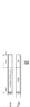
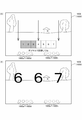
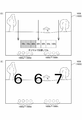
次に、遊技盤4における機能表示ユニット1180について図10を参照して説明する。この機能表示ユニット1180は、前構成部材1110の所定位置に取り付けて配置されるものである。図10はパチンコ遊技機に取り付けた状態で遊技盤における機能表示ユニットを拡大して示す正面図である。
[6. Function display unit]
Next, the
機能表示ユニット1180は、図10に拡大して示すように、正面視左側端部に遊技領域1100内へ打ち込まれた遊技球によって変化する遊技状態を表示するための1つのLEDからなる遊技状態表示器1183と、遊技状態表示器1183の右側で上下方向へ並んだ2つのLEDからなり上始動口2101への遊技球の受け入れに関する保留数を表示するための上特別図柄記憶表示器1184と、上特別図柄記憶表示器1184の右側に配置され上始動口2101への遊技球の受け入れにより抽選された第一特別抽選結果を第一特別図柄として表示するための1つの7セグメントLEDからなる上特別図柄表示器1185と、上特別図柄表示器1185の右斜め上に配置され下始動口2102への遊技球の受け入れにより抽選された第二特別抽選結果を第二特別図柄として表示するための1つの7セグメントLEDからなる下特別図柄表示器1186と、下特別図柄表示器1186の右側で上下方向へ並んだ2つのLEDからなり下始動口2102への遊技球の受け入れに関する保留数を表示するための下特別図柄記憶表示器1187と、を備えている。
As shown enlarged in FIG. 10, the
機能表示ユニット1180の表示部1181には、下特別図柄表示器1186の直上から内周レール1113に略沿った円弧状に並んで配置され遊技球によるゲート部2350の通過に関する保留数を表示するための4つのLEDからなる普通図柄記憶表示器1188と、普通図柄記憶表示器の下側に配置され遊技球がゲート部2350を通過することで抽選された普通抽選結果を普通図柄として表示するための1つのLEDからなる普通図柄表示器1189と、普通図柄記憶表示器1188の斜め右上側へ並んで配置され第一特別抽選結果又は第二特別抽選結果が「大当り」の時に大入賞口2103の開閉パターンの繰返し回数(ラウンド数)を表示するための2つのLEDからなるラウンド表示器1190と、を備えている。
The
遊技状態表示器1183は、赤色・緑色・橙色と、その発光色を変化させることが可能なフルカラーLEDとされており、発光する発光色と、点灯・点滅との組合せにより、様々な遊技状態(例えば、確率変動状態、時間短縮状態、確変時短状態、大当り遊技状態、小当り遊技状態、等)を表示することができるようになっている。
The
上特別図柄記憶表示器1184は、上特別図柄表示器1185において第一特別図柄を変動表示させることができない時に、上始動口2101へ遊技球が受け入れられた場合に、変動表示の開始が保留(記憶)された第一特別図柄の保留数(記憶数)を表示するものである。この上特別図柄記憶表示器1184は、所定のLEDからなる上特別図柄記憶ランプ1184aと、上特別図柄記憶ランプ1184bとを有しており、上特別図柄記憶ランプ1184a,1184bの点灯・点滅パターンによって、保留数を表示することができるようになっている。具体的には、例えば、保留数が1つの時には上特別図柄記憶ランプ1184aが点灯して上特別図柄記憶ランプ1184bが消灯し、保留数が2つの時には上特別図柄記憶ランプ1184a,1184bがともに点灯し、保留数が3つの時には上特別図柄記憶ランプ1184aが点滅して上特別図柄記憶ランプ1184bが点灯し、保留数が4つの時には上特別図柄記憶ランプ1184a,1184bがともに点滅するようになっている。なお、本実施形態では、4つまで保留されるようになっている。
When the upper special
下特別図柄記憶表示器1187は、下特別図柄表示器1186において第二特別図柄を変動表示させることができない時に、下始動口2102へ遊技球が受け入れられた場合に、変動表示の開始が保留(記憶)された第二特別図柄の保留数(記憶数)を表示するものである。この下特別図柄記憶表示器1187は、所定のLEDからなる下特別図柄記憶ランプ1187aと、下特別図柄記憶ランプ1187bとを有しており、下特別図柄記憶ランプ1187a,1187bの点灯・点滅パターンによって、保留数を表示することができるようになっている。具体的には、例えば、保留数が1つの時には下特別図柄記憶ランプ1187aが点灯して下特別図柄記憶ランプ1187bが消灯し、保留数が2つの時には下特別図柄記憶ランプ1187a,1187bがともに点灯し、保留数が3つの時には下特別図柄記憶ランプ1187aが点滅して下特別図柄記憶ランプ1187bが点灯し、保留数が4つの時には下特別図柄記憶ランプ1187a,1187bがともに点滅するようになっている。なお、本実施形態では、4つまで保留されるようになっている。
The lower special
上特別図柄表示器1185及び下特別図柄表示器1186は、上始動口2101や下始動口2102への遊技球の受け入れにより、抽選された第一特別抽選結果や第二特別抽選結果を表示するものであり、7セグメントLEDが特別抽選結果に応じた所定の時間、変動した後に停止し、停止した7セグメントLEDの発光パターン(特別図柄)によって、第一特別抽選結果や第二特別抽選結果を遊技者側に認識させることができるようになっている(変動表示ゲーム)。
The upper
普通図柄表示器1189は、赤色・緑色・橙色と、その発光色を変化させることが可能なフルカラーLEDとされており、発光する発光色と、点灯・点滅との組合せにより、ゲート部2350を遊技球が通過することで抽選される普通抽選結果を表示することができるようになっている。なお、普通図柄表示器1189による普通図柄の表示も、特別図柄と同様に、所定時間変動表示した後に、普通抽選結果に対応した発光パターンで停止表示するようになっている。
The
普通図柄記憶表示器1188は、普通図柄表示器1189において普通図柄を変動表示させることができない時に、ゲート部2350を遊技球が通過した場合に、変動表示の開始が保留(記憶)された普通図柄の保留数(記憶数)を表示するものである。この普通図柄記憶表示器1188は、下から並んで配置された4つの普通図柄記憶ランプ1188a〜1188dを備え、それぞれが所定のLEDとされており、保留数に応じて下から普通図柄記憶ランプ1188a〜1188dを順次点灯させることで普通図柄の保留数を表示させることができるようになっている。なお、本実施形態では、普通図柄の変動表示が4つまで保留(記憶)されるようになっている。
The normal
ラウンド表示器1190は、所定のLEDからなる2ラウンド表示ランプ1190aと、15ラウンド表示ランプ1190bとを備えており、それぞれのランプが点灯することで「大当り」遊技におけるラウンド数を表示することができるようになっている。
The
また、機能表示ユニット1180は、図10に示すように、遊技盤4をパチンコ遊技機1に取り付けた状態で、扉枠5の遊技窓101を通して遊技者側から視認することができるようになっている。遊技状態表示器1183、上特別図柄記憶表示器1184、上特別図柄表示器1185、下特別図柄表示器1186、下特別図柄記憶表示器1187、普通図柄記憶表示器1188、普通図柄表示器1189、及びラウンド表示器1190は、機能表示基板1191の前面に取り付けられている。なお、機能表示ユニット1180の後方突出部の後端には、機能表示基板1191と主制御基板4100とを接続するための接続端子が取り付けられている。
Further, as shown in FIG. 10, the
本実施形態では、機能表示ユニット1180を遊技盤4の前構成部材1110に備えるようにしているので、遊技パネル1150に取り付けられる表ユニット2000や裏ユニット3000に備えるようにした場合と比較して、機能表示ユニット1180を遊技盤4の基本構成として流用することができ、パチンコ遊技機1に係る構成を簡略化してコストが増加するのを防止することができるとともに、パチンコ遊技機1の機種(表ユニット2000や裏ユニット3000により具現化されパチンコ遊技機1の機種を特徴付けることが可能な遊技盤4の詳細構成)が異なっていても、機能表示ユニット1180の位置が変化しないので、遊技者や遊技ホールの店員等に対して、戸惑うことなく機能表示ユニット1180の位置を認識させることができるようになっている。
In the present embodiment, since the
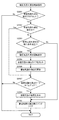
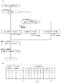
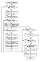
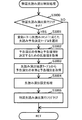
[7.主制御基板、払出制御基板及び周辺制御基板]
次に、パチンコ遊技機1の各種制御を行う制御基板について、図11〜図14を参照して説明する。図11は主制御基板、払出制御基板及び周辺制御基板のブロック図であり、図12は図11のつづきを示すブロック図であり、図13は周辺制御MPUの概略を示すブロック図であり、図14は液晶及び音制御部における音源内蔵VDP周辺のブロック図である。
[7. Main control board, payout control board and peripheral control board]
Next, a control board that performs various controls of the
パチンコ遊技機1の制御構成は、図11に示すように、主制御基板4100、払出制御基板4110及び周辺制御基板4140から主として構成されており、各種制御が分担されている。まず、主制御基板について説明し、続いて払出制御基板、電源基板、そして周辺制御基板について説明する。
As shown in FIG. 11, the control configuration of the
[7−1.主制御基板]
遊技の進行を制御する主制御基板4100は、図11に示すように、電源投入時に実行される電源投入時処理を制御するとともに電源投入時から所定時間が経過した後に実行されるとともに遊技動作を制御する主制御プログラムなどの各種制御プログラムや各種コマンドを記憶するROMや一時的にデータを記憶するRAM等が内蔵されるマイクロプロセッサである主制御MPU4100aと、各種検出スイッチからの検出信号が入力される主制御入力回路4100bと、各種信号を外部の基板等へ出力するための主制御出力回路4100cと、各種ソレノイドを駆動するための主制御ソレノイド駆動回路4100dと、予め定めた電圧の停電又は瞬停の兆候を監視する停電監視回路4100eと、を主として備えている。
[7-1. Main control board]
As shown in FIG. 11, the
主制御MPU4100aには、その内蔵されているRAM(以下、「主制御内蔵RAM」と記載する。)や、その内蔵されているROM(以下、「主制御内蔵ROM」と記載する。)のほかに、その動作(システム)を監視するウォッチドックタイマや不正を防止するための機能等も内蔵されている。 In addition to the built-in RAM (hereinafter, referred to as "main control built-in RAM") and the built-in ROM (hereinafter, referred to as "main control built-in ROM") of the main control MPU4100a. It also has a built-in watchdog timer that monitors its operation (system) and a function to prevent fraud.
また、主制御MPU4100aは、不揮発性の記憶手段が内蔵されている。この不揮発性の記憶手段には、主制御MPU4100aを製造したメーカによって個体を識別するためのユニークな符号(世界で1つしか存在しない符号)が付された固有のIDコードが予め記憶されている。この一度付されたIDコードは、不揮発性の記憶手段に記憶されるため、外部装置を用いても書き換えることができない。主制御MPU4100aは、不揮発性の記憶手段からIDコードを取り出して参照することができる。 Further, the main control MPU4100a has a built-in non-volatile storage means. In this non-volatile storage means, a unique ID code with a unique code (a code that exists only once in the world) for identifying an individual by the manufacturer of the main control MPU4100a is stored in advance. .. Since the ID code once attached is stored in the non-volatile storage means, it cannot be rewritten even by using an external device. The main control MPU4100a can take out the ID code from the non-volatile storage means and refer to it.
主制御入力回路4100bは、その各種入力端子に各種検出スイッチからの検出信号がそれぞれ入力された情報を強制的にリセットするためのリセット端子が設けられず、リセット機能を有していない。このため、主制御入力回路4100bは、後述する主制御システムリセットからのシステムリセット信号が入力されない回路として構成されている。つまり、主制御入力回路4100bは、その各種入力端子に入力されている各種検出スイッチからの検出信号に基づく情報が後述する主制御システムリセットによりリセットされないことによって、その情報に基づく各種信号がその各種出力端子から出力される回路として構成されている。
The main
主制御出力回路4100cは、エミッタ端子がグランド(GND)と接地されたオープンコレクタ出力タイプとして回路構成されており、その各種入力端子に各種信号を外部の基板等へ出力するための各種信号が入力された情報を強制的にリセットするためのリセット端子が設けられるリセット機能を有するリセット機能付き主制御出力回路4100caと、リセット端子が設けられていないリセット機能を有しないリセット機能なし主制御出力回路4100cbと、から構成されている。リセット機能付き主制御出力回路4100caは、後述する主制御システムリセットからのシステムリセット信号が入力される回路として構成されている。つまり、リセット機能付き主制御出力回路4100caは、その各種入力端子に入力されている各種信号を外部の基板等へ出力するための情報が後述する主制御システムリセットによりリセットされることによって、その情報に基づく信号がその各種出力端子から全く出力されない回路として構成されている。これに対して、リセット機能なし主制御出力回路4100cbは、後述する主制御システムリセットからのシステムリセット信号が入力されない回路として構成されている。つまり、リセット機能なし主制御出力回路4100cbは、その各種入力端子に入力されている各種信号を外部の基板等へ出力するための情報が後述する主制御システムリセットによりリセットされないことによって、その情報に基づく信号がその各種出力端子から出力される回路として構成されている。
The main
図8に示した、上始動口2101に入球した遊技球を検出する上始動口スイッチ3022、下始動口2102に入球した遊技球を検出する下始動口スイッチ2109、及び一般入賞口2104に入球した遊技球を検出する一般入賞口スイッチ3020からの検出信号や停電監視回路4100eからの信号は、主制御入力回路4100bを介して主制御MPU4100aの所定の入力ポートの入力端子に入力されている。また、図8に示した、ゲート部2350を通過した遊技球を検出するゲートスイッチ2352、一般入賞口2201に入球した遊技球を検出する一般入賞口スイッチ3020、大入賞口2103に入球した遊技球を検出するカウントスイッチ2110、及び図9に示した裏ユニット3000に取り付けられて磁石を用いた不正行為を検出する磁気検出スイッチ3024からの検出信号は、遊技盤4に取り付けられたパネル中継端子板4161、そして主制御入力回路4100bを介して主制御MPU4100aの所定の入力ポートの入力端子に入力されている。
The upper
主制御MPU4100aは、これらの各スイッチからの検出信号に基づいて、その所定の出力ポートの出力端子からリセット機能付き主制御出力回路4100caに駆動信号を出力することにより、リセット機能付き主制御出力回路4100caから主制御ソレノイド駆動回路4100dに制御信号を出力し、主制御ソレノイド駆動回路4100dからパネル中継端子板4161を介して始動口ソレノイド2105及びアタッカソレノイド2108に駆動信号を出力したり、その所定の出力ポートの出力端子からリセット機能付き主制御出力回路4100caに駆動信号を出力することにより、リセット機能付き主制御出力回路4100caからパネル中継端子板4161、そして機能表示基板1191を介して上特別図柄表示器1185、下特別図柄表示器1186、上特別図柄記憶表示器1184、下特別図柄記憶表示器1187、普通図柄表示器1189、普通図柄記憶表示器1188、遊技状態表示器1183、及びラウンド表示器1190に駆動信号を出力したりする。
The
また、主制御MPU4100aは、その所定の出力ポートの出力端子からリセット機能付き主制御出力回路4100caに遊技に関する各種情報(遊技情報)を出力することにより、リセット機能付き主制御出力回路4100caから払出制御基板4110に各種情報(遊技情報)を出力したり、その所定の出力ポートの出力端子からリセット機能付き主制御出力回路4100caに信号(停電クリア信号)を出力することにより、リセット機能付き主制御出力回路4100caから停電監視回路4100eに信号(停電クリア信号)を出力したりする。
Further, the
なお、本実施形態おいて、上始動口スイッチ3022、下始動口スイッチ2109、ゲートスイッチ2352、及びカウントスイッチ2110には、非接触タイプの電磁式の近接スイッチを用いているのに対して、一般入賞口スイッチ3020,3020には、接触タイプのON/OFF動作式のメカニカルスイッチを用いている。これは、遊技球が上始動口2101や下始動口2102に頻繁に入球するし、ゲート部2350を頻繁に通過するため、上始動口スイッチ3022、下始動口スイッチ2109、及びゲートスイッチ2352による遊技球の検出も頻繁に発生する。このため、上始動口スイッチ3022、下始動口スイッチ2109、及びゲートスイッチ2352には、寿命の長い近接スイッチを用いている。また、遊技者にとって有利となる大当り遊技状態が発生すると、大入賞口2103が開放されて遊技球が頻繁に入球するため、カウントスイッチ2110による遊技球の検出も頻繁に発生する。このため、カウントスイッチ2110にも、寿命の長い近接スイッチを用いている。これに対して、遊技球が頻繁に入球しない一般入賞口2104,2201には、一般入賞口スイッチ3020,3020による検出も頻繁に発生しない。このため、一般入賞口スイッチ3020,3020には、近接スイッチより寿命が短いメカニカルスイッチを用いている。
In the present embodiment, the upper
また、主制御MPU4100aは、その所定のシリアル出力ポートの出力端子からリセット機能なし主制御出力回路4100cbに払い出しに関する各種コマンドをシリアルデータとして送信することにより、リセット機能なし主制御出力回路4100cbから払出制御基板4110に各種コマンドをシリアルデータとして送信する。払出制御基板4110は、主制御基板4100からの各種コマンドをシリアルデータとして正常受信完了すると、その旨を伝える信号(払主ACK信号)を主制御基板4100に出力する。この信号(払主ACK信号)が主制御入力回路4100bを介して主制御MPU4100aの所定の入力ポートの入力端子に入力されるようになっている。
Further, the
また、主制御MPU4100aは、払出制御基板4110からのパチンコ遊技機1の状態に関する各種コマンドをシリアルデータとして主制御入力回路4100bで受信することにより、主制御入力回路4100bからその所定のシリアル入力ポートの入力端子で各種コマンドをシリアルデータとして受信する。主制御MPU4100aは、払出制御基板4110からの各種コマンドをシリアルデータとして正常受信完了すると、その旨を伝える信号(主払ACK信号)を、その所定の出力ポートの出力端子からリセット機能付き主制御出力回路4100caに出力し、リセット機能付き主制御出力回路4100caから払出制御基板4110に信号(主払ACK信号)を出力する。
Further, the
また、主制御MPU4100aは、その所定のシリアル出力ポートの出力端子からリセット機能なし主制御出力回路4100cbに遊技演出の制御に関する各種コマンド及びパチンコ遊技機1の状態に関する各種コマンドをシリアルデータとして送信することにより、リセット機能なし主制御出力回路4100cbから周辺制御基板4140に各種コマンドをシリアルデータとして送信する。
Further, the
ここで、周辺制御基板4140へ各種コマンドをシリアルデータとして送信する主周シリアル送信ポートについて簡単に説明する。主制御MPU4100aは、主制御CPUコア4100aaを中心として構成されており、主制御内蔵RAMのほかに、主制御各種シリアルI/Oポートの1つである主周シリアル送信ポート4100ae等がバス4100ahを介して回路接続されている。主周シリアル送信ポート4100aeは、周辺制御基板4140へ各種コマンドを主周シリアルデータとして送信するものであり、送信シフトレジスタ4100aea、送信バッファレジスタ4100aeb、シリアル管理部4100aec等を主として構成されている。主制御CPUコア4100aaは、コマンドを送信バッファレジスタ4100aebにセットして送信開始信号をシリアル管理部4100aecに出力すると、このシリアル管理部4100aecが送信バッファレジスタ4100aebにセットされたコマンドを送信バッファレジスタ4100aebから送信シフトレジスタ4100aeaに転送して主周シリアルデータとして周辺制御基板4140に送信開始する。本実施形態では、送信バッファレジスタ4100aebの記憶容量として32バイトを有している。主制御CPUコア4100aaは、送信バッファレジスタ4100aebに複数のコマンドをセットした後にシリアル管理部4100aecに送信開始信号を出力することによって複数のコマンドを連続的に周辺制御基板4140に送信している。なお、周辺制御基板4140への各種コマンドの送信は、シリアルデータとして送信する方式に限定されず、パラレルデータとして通信する方式であってもよい。パラレルデータとして送信する場合、プログラム処理として、パラレルデータとして送信するための専用の処理を設け、所定タイミング(例えば、リングバッファにコマンドが格納されたタイミング若しくは格納されていることを条件)により実行することで、個々のコマンドを必要なタイミングで送信するようにしてもよい。
Here, the main peripheral serial transmission port that transmits various commands as serial data to the
なお、主制御基板4100に各種電圧を供給する電源基板851は、電源遮断時にでも所定時間、主制御基板4100に電力を供給するためのバックアップ電源としての電気二重層キャパシタ(以下、単に「キャパシタ」と記載する。)BC0を備えている。このキャパシタBC0により主制御MPU4100aは、電源遮断時にでも電源断時処理において各種情報を主制御内蔵RAMに記憶することができるようになっている。主制御内蔵RAMに記憶される各種情報は、電源投入時から予め定めた期間内に後述する払出制御基板4110の操作スイッチ860aが操作されると、操作スイッチ860aからの操作信号(RAMクリア信号)が払出制御基板4110から出力され、主制御入力回路4100bを介して、主制御MPU4100aの所定の入力ポートの入力端子に入力され、これを契機として、主制御MPU4100aによって主制御内蔵RAMから完全に消去(クリア)されるようになっている。
The
[7−2.周辺制御基板]
周辺制御基板4140は、図12に示すように、主制御基板4100からの各種コマンドに基づいて演出制御を行う周辺制御部4150と、遊技盤側液晶表示装置1900及び上皿側液晶表示装置470の描画制御と本体枠3に設けた図5に示したスピーカボックス820に収容されるスピーカ及び扉枠5に設けたスピーカ130から流れる音楽や効果音等の音制御とを行う液晶及び音制御部4160と、年月日を特定するカレンダー情報と時分秒を特定する時刻情報とを保持するリアルタイムクロック(以下、「RTC」と記載する。)制御部4165と、本体枠3に設けたスピーカボックス820に収容されるスピーカ及び扉枠5に設けたスピーカ130から流れる音楽や効果音等の音量をつまみ部を回動操作することにより調節する音量調整ボリューム4140aと、を備えている。
[7-2. Peripheral control board]
As shown in FIG. 12, the
[7−2−1.周辺制御部]
演出制御を行う周辺制御部4150は、図12に示すように、マイクロプロセッサとしての周辺制御MPU4150aと、電源投入時に実行される電源投入時処理を制御するとともに電源投入時から所定時間が経過した後に実行されるとともに演出動作を制御するサブ制御プログラムなどの各種制御プログラム、各種データ、各種制御データ及び各種スケジュールデータを記憶する周辺制御ROM4150bと、後述する液晶及び音制御部4160の音源内蔵VDP4160aからのVブランク信号が入力されるごとに実行される周辺制御部定常処理をまたいで継続される各種情報(例えば、遊技盤側液晶表示装置1900に描画する画面を規定するスケジュールデータや各種LED等の発光態様を規定するスケジュールデータなどを管理するための情報など)を記憶する周辺制御RAM4150cと、日をまたいで継続される各種情報(例えば、大当り遊技状態が発生した履歴を管理するための情報や特別な演出フラグの管理するための情報など)を記憶する周辺制御SRAM4150dと、周辺制御MPU4150aが正常に動作しているか否かを監視するための周辺制御外部ウォッチドックタイマ4150e(以下、「周辺制御外部WDT4150e」と記載する。)と、を備えている。
[7-2-1. Peripheral control unit]
As shown in FIG. 12, the peripheral control unit 4150 that performs the effect control controls the
周辺制御RAM4150cは、瞬停が発生して電力がすぐ復帰する程度の時間しか記憶された内容を保持することができず、電力が長時間遮断された状態(長時間の電断が発生した場合)ではその内容を失うのに対して、周辺制御SRAM4150dは、電源基板851に設けられた図示しない大容量の電解コンデンサ(以下、「SRAM用電解コンデンサ」と記載する。)によりバックアップ電源が供給されることにより、記憶された内容を50時間程度、保持することができるようになっている。電源基板851にSRAM用電解コンデンサが設けられることにより、遊技盤4をパチンコ遊技機1から取り外した場合には、周辺制御SRAM4150dにバックアップ電源が供給されなくなるため、周辺制御SRAM4150dは、記憶された内容を保持することができなくなってその内容を失う。
The peripheral control RAM 4150c can hold the stored contents only for a time when a momentary power failure occurs and the power is immediately restored, and the power is cut off for a long time (when a long-time power interruption occurs). ), The peripheral control SRAM 4150d is supplied with backup power by a large-capacity electrolytic capacitor (hereinafter, referred to as "electrolytic capacitor for SRAM") provided on the
周辺制御外部WDT4150eは、周辺制御MPU4150aのシステムが暴走していないかを監視するためのタイマであり、このタイマがタイマアップすると、ハードウェア的にリセットをかけるようになっている。つまり、周辺制御MPU4150aは、一定期間内(タイマがタイマアップするまで)に周辺制御外部WDT4150eのタイマをクリアするクリア信号を周辺制御外部WDT4150eに出力しないときには、リセットがかかることとなる。周辺制御MPU4150aは、一定期間内にクリア信号を周辺制御外部WDT4150eに出力するときには、周辺制御外部WDT4150eのタイマカウントを再スタートさせることができるため、リセットがかからない。 The peripheral control external WDT4150e is a timer for monitoring whether the system of the peripheral control MPU4150a is out of control, and when the timer is up, it is reset by hardware. That is, if the peripheral control MPU4150a does not output a clear signal for clearing the timer of the peripheral control external WDT4150e to the peripheral control external WDT4150e within a certain period of time (until the timer starts up), the peripheral control MPU4150a will be reset. When the peripheral control MPU4150a outputs a clear signal to the peripheral control external WDT4150e within a certain period of time, the timer count of the peripheral control external WDT4150e can be restarted, so that the reset is not applied.
周辺制御MPU4150aは、パラレルI/Oポート、シリアルI/Oポート等を複数内蔵しており、主制御基板4100からの各種コマンドを受信すると、この各種コマンドに基づいて、遊技盤4の各装飾基板に設けた複数のLED等への点灯信号、点滅信号又は階調点灯信号を出力するための遊技盤側発光データをランプ駆動基板用シリアルI/Oポートから図示しない周辺制御出力回路を介してランプ駆動基板4170に送信したり、遊技盤4に設けた各種可動体を作動させるモータやソレノイド等の電気的駆動源への駆動信号を出力するための遊技盤側モータ駆動データをモータ駆動基板用シリアルI/Oポートから周辺制御出力回路を介してモータ駆動基板4180に送信したり、扉枠5に設けたダイヤル駆動モータ414等の電気的駆動源への駆動信号を出力するための扉側モータ駆動データを枠装飾駆動アンプ基板モータ用シリアルI/Oポートから周辺制御出力回路、枠周辺中継端子板868、そして周辺扉中継端子板882を介して枠装飾駆動アンプ基板194に送信したり、扉枠5の各装飾基板に設けた複数のLED等への点灯信号、点滅信号又は階調点灯信号を出力するための扉側発光データを枠装飾駆動アンプ基板LED用シリアルI/Oポートから周辺制御出力回路、枠周辺中継端子板868、そして周辺扉中継端子板882を介して枠装飾駆動アンプ基板194に送信したりする。
The
主制御基板4100からの各種コマンドは、図示しない周辺制御入力回路を介して、周辺制御MPU4150aの主制御基板用シリアルI/Oポートに入力されている。また、操作ユニット400に設けられた、ダイヤル操作部401の回転(回転方向)を検出するための回転検出スイッチからの検出信号、及び押圧操作部405の操作を検出するための押圧検出スイッチからの検出信号は、枠装飾駆動アンプ基板194に設けた図示しない扉側シリアル送信回路でシリアル化され、このシリアル化された操作ユニット検出データが扉側シリアル送信回路から、周辺扉中継端子板882、枠周辺中継端子板868、そして周辺制御入力回路を介して、周辺制御MPU4150aの操作ユニット検出用シリアルI/Oポートに入力されている。
Various commands from the
遊技盤4に設けた各種可動体の原位置や可動位置等を検出するための各種検出スイッチ(例えば、フォトセンサなど。)からの検出信号は、モータ駆動基板4180に設けた図示しない遊技盤側シリアル送信回路でシリアル化され、このシリアル化された可動体検出データが遊技盤側シリアル送信回路から周辺制御入力回路を介して、周辺制御MPU4150aのモータ駆動基板用シリアルI/Oポートに入力されている。周辺制御MPU4150aは、モータ駆動基板用シリアルI/Oポートの入出力を切り替えることにより周辺制御基板4140とモータ駆動基板4180との基板間における各種データのやり取りを行うようになっている。
Detection signals from various detection switches (for example, a photo sensor) for detecting the original position, movable position, etc. of various movable bodies provided on the
なお、周辺制御MPU4150aは、ウォッチドックタイマを内蔵(以下、「周辺制御内蔵WDT」と記載する。)しており、周辺制御内蔵WDTと周辺制御外部WDT4150eとを併用して自身のシステムが暴走しているか否かを診断している。 The peripheral control MPU4150a has a built-in watchdog timer (hereinafter referred to as "peripheral control built-in WDT"), and its own system runs out of control by using the peripheral control built-in WDT and the peripheral control external WDT4150e together. I am diagnosing whether or not it is.
[7−2−1a.周辺制御MPU]
次に、マイクロコンピュータである周辺制御MPU4150aについて説明する。周辺制御MPU4150aは、図13に示すように、周辺制御CPUコア4150aaを中心として、周辺制御内蔵RAM4150ab、周辺制御DMA(Direct Memory Accessの略)コントローラ4150ac、周辺制御バスコントローラ4150ad、周辺制御各種シリアルI/Oポート4150ae、周辺制御内蔵WDT4150af、周辺制御各種パラレルI/Oポート4150ag、及び周辺制御アナログ/デジタルコンバータ(以下、周辺制御A/Dコンバータと記載する)4150ak等から構成されている。
[7-2-1a. Peripheral control MPU]
Next, the peripheral control MPU4150a, which is a microcomputer, will be described. As shown in FIG. 13, the
周辺制御CPUコア4150aaは、周辺制御内蔵RAM4150ab、周辺制御DMAコントローラ4150acに対して、内部バス4150ahを介して、各種データを読み書きする一方、周辺制御各種シリアルI/Oポート4150ae、周辺制御内蔵WDT4150af、周辺制御各種パラレルI/Oポート4150ag、及び周辺制御A/Dコンバータ4150akに対して、内部バス4150ah、周辺制御バスコントローラ4150ad、そして周辺バス4150aiを介して、各種データを読み書きする。 Peripheral control CPU core 4150aa reads and writes various data to peripheral control built-in RAM 4150ab and peripheral control DMA controller 4150ac via internal bus 4150ah, while peripheral control various serial I / O ports 4150ae, peripheral control built-in WDT4150af, Peripheral control Various data are read and written to the various parallel I / O ports 4150ag and the peripheral control A / D converter 4150ak via the internal bus 4150ah, the peripheral control bus controller 4150ad, and the peripheral bus 4150ai.
また、周辺制御CPUコア4150aaは、周辺制御ROM4150bに対して、内部バス4150ah、周辺制御バスコントローラ4150ad、そして外部バス4150hを介して、各種データを読み込む一方、周辺制御RAM4150c、及び周辺制御SRAM4150dに対して、内部バス4150ah、周辺制御バスコントローラ4150ad、そして外部バス4150hを介して、各種データを読み書きする。 Further, the peripheral control CPU core 4150aa reads various data to the peripheral control ROM 4150b via the internal bus 4150ah, the peripheral control bus controller 4150ad, and the external bus 4150h, while reading the peripheral control RAM 4150c and the peripheral control SRAM 4150d. Then, various data are read and written via the internal bus 4150ah, the peripheral control bus controller 4150ad, and the external bus 4150h.
周辺制御DMAコントローラ4150acは、周辺制御内蔵RAM4150ab、周辺制御ROM4150b、周辺制御RAM4150c、及び周辺制御SRAM4150d等の記憶装置と、周辺制御各種シリアルI/Oポート4150ae、周辺制御内蔵WDT4150af、周辺制御各種パラレルI/Oポート4150ag、及び周辺制御A/Dコンバータ4150ak等の入出力装置と、の装置間において、周辺制御CPUコア4150aaを介すことなく、独立してデータ転送を行う専用のコントローラであり、DMA0〜DMA3という4つのチャンネルを有している。 The peripheral control DMA controller 4150ac includes storage devices such as peripheral control built-in RAM 4150ab, peripheral control ROM 4150b, peripheral control RAM 4150c, and peripheral control SRAM 4150d, peripheral control various serial I / O ports 4150ae, peripheral control built-in WDT4150af, and peripheral control parallel I. It is a dedicated controller that independently transfers data between the / O port 4150ag and the input / output device such as the peripheral control A / D converter 4150ak without going through the peripheral control CPU core 4150aa, and is DMA0. It has four channels, ~ DMA3.
具体的には、周辺制御DMAコントローラ4150acは、周辺制御MPU4150aに内蔵される周辺制御内蔵RAM4150abの記憶装置と、周辺制御MPU4150aに内蔵される、周辺制御各種シリアルI/Oポート4150ae、周辺制御内蔵WDT4150af、周辺制御各種パラレルI/Oポート4150ag、及び周辺制御A/Dコンバータ4150ak等の入出力装置と、の装置間において、周辺制御CPUコア4150aaを介すことなく、独立してデータ転送を行うために、周辺制御内蔵RAM4150abの記憶装置に対して、内部バス4150ahを介して、読み書きする一方、周辺制御各種シリアルI/Oポート4150ae、周辺制御内蔵WDT4150af、周辺制御各種パラレルI/Oポート4150ag、及び周辺制御A/Dコンバータ4150ak等の入出力装置に対して、周辺制御バスコントローラ4150ad及び周辺バス4150aiを介して、読み書きする。
Specifically, the peripheral control DMA controller 4150ac includes a storage device of the peripheral control built-in RAM 4150ab built in the
また、周辺制御DMAコントローラ4150acは、周辺制御MPU4150aに外付けされる、周辺制御ROM4150b、周辺制御RAM4150c、及び周辺制御SRAM4150d等の記憶装置と、周辺制御MPU4150aに内蔵される、周辺制御各種シリアルI/Oポート4150ae、周辺制御内蔵WDT4150af、周辺制御各種パラレルI/Oポート4150ag、及び周辺制御A/Dコンバータ4150ak等の入出力装置と、の装置間において、周辺制御CPUコア4150aaを介すことなく、独立してデータ転送を行うために、周辺制御ROM4150b、周辺制御RAM4150c、及び周辺制御SRAM4150d等の記憶装置に対して、周辺制御バスコントローラ4150ad及び外部バス4150hを介して、読み書きする一方、周辺制御各種シリアルI/Oポート4150ae、周辺制御内蔵WDT4150af、周辺制御各種パラレルI/Oポート4150ag、及び周辺制御A/Dコンバータ4150ak等の入出力装置に対して、周辺制御バスコントローラ4150ad及び周辺バス4150aiを介して、読み書きする。
Further, the peripheral control DMA controller 4150ac includes a storage device such as a peripheral control ROM 4150b, a peripheral control RAM 4150c, and a peripheral control SRAM 4150d externally attached to the
周辺制御バスコントローラ4150adは、内部バス4150ah、周辺バス4150ai、及び外部バス4150hをコントロールして周辺制御CPUコア4150aaの中央処理装置と、周辺制御内蔵RAM4150ab、周辺制御ROM4150b、周辺制御RAM4150c、及び周辺制御SRAM4150d等の記憶装置と、周辺制御各種シリアルI/Oポート4150ae、周辺制御内蔵WDT4150af、周辺制御各種パラレルI/Oポート4150ag、及び周辺制御A/Dコンバータ4150ak等の入出力装置と、の各種装置間において、各種データのやり取りを行う専用のコントローラである。 The peripheral control bus controller 4150ad controls the internal bus 4150ah, the peripheral bus 4150ai, and the external bus 4150h to control the central processing unit of the peripheral control CPU core 4150aa, the peripheral control built-in RAM 4150ab, the peripheral control ROM 4150b, the peripheral control RAM 4150c, and the peripheral control. Various devices such as a storage device such as SRAM 4150d, various peripheral control serial I / O ports 4150ae, WDT4150af with built-in peripheral control, various parallel I / O ports 4150ag for peripheral control, and input / output devices such as peripheral control A / D converter 4150ak. It is a dedicated controller that exchanges various data between them.
周辺制御各種シリアルI/Oポート4150aeは、ランプ駆動基板用シリアルI/Oポート、モータ駆動基板用シリアルI/Oポート、枠装飾駆動アンプ基板モータ用シリアルI/Oポート、枠装飾駆動アンプ基板LED用シリアルI/Oポート、枠装飾駆動アンプ基板モータ用シリアルI/Oポート、主制御基板用シリアルI/Oポート、及び操作ユニット情報取得用シリアルI/Oポートを有している。 Peripheral control Various serial I / O ports 4150ae are a serial I / O port for a lamp drive board, a serial I / O port for a motor drive board, a serial I / O port for a frame decoration drive amplifier board motor, and a frame decoration drive amplifier board LED. It has a serial I / O port for, a serial I / O port for a frame decoration drive amplifier board motor, a serial I / O port for a main control board, and a serial I / O port for acquiring operation unit information.
周辺制御内蔵ウォッチドックタイマ(周辺制御内蔵WDT)4150afは、周辺制御MPU4150aのシステムが暴走していないかを監視するためのタイマであり、このタイマがタイマアップすると、ハードウェア的にリセットをかけるようになっている。つまり、周辺制御CPUコア4150aaは、ウォッチドックタイマをスタートさせた場合には、一定期間内(タイマがタイマアップするまで)にそのタイマをクリアするクリア信号を周辺制御内蔵WDT4150afに出力しないときには、リセットがかかることとなる。周辺制御CPUコア4150aaは、ウォッチドックタイマをスタートさせて一定期間内にクリア信号を周辺制御内蔵WDT4150afに出力するときには、タイマカウントを再スタートさせることができるため、リセットがかからない。
The peripheral control built-in watchdog timer (WDT with built-in peripheral control) 4150af is a timer for monitoring whether the system of the
周辺制御各種パラレルI/Oポート4150agは、遊技盤側モータ駆動ラッチ信号、扉側モータ駆動発光ラッチ信号等の各種ラッチ信号を出力するほかに、周辺制御外部WDT4150eにクリア信号を出力したり、遊技盤4に設けた各種可動体の原位置や可動位置等を検出するための各種検出スイッチからの検出信号をモータ駆動基板4180に設けた図示しない遊技盤側シリアル送信回路でシリアル化して、このシリアル化された可動体検出データを遊技盤側シリアル送信回路から周辺制御MPU4150aのモータ駆動基板用シリアルI/Oポートで受信するための可動体情報取得ラッチ信号を出力したり、扉枠5における上部装飾ユニット280の上部装飾基板に実装されたLEDの点灯信号を出力したりする。このLEDは、高輝度の白色LEDであり、大当り遊技状態の発生が確定している旨を伝えるための確定告知ランプとなっている。本実施形態では、LEDと周辺制御各種パラレルI/Oポート4150agとが電気的に直接接続された構成を採用することにより、LEDと周辺制御各種パラレルI/Oポート4150agとの経路を短くすることで遊技上重量な意味を持つLEDの点灯制御についてノイズ対策を講ずることができる。なお、LEDの点灯制御については、後述する周辺制御部1msタイマ割り込み処理において実行されるようになっており、このLEDを除く他のLED等は、後述する周辺制御部定常処理において実行されるようになっている。
Peripheral control Various parallel I / O ports 4150ag output various latch signals such as game board side motor drive latch signal and door side motor drive light emission latch signal, as well as output clear signal to peripheral control external WDT4150e, and play games. Detection signals from various detection switches for detecting the original position, movable position, etc. of various movable bodies provided on the
周辺制御A/Dコンバータ4150akは、音量調整ボリューム4140aと電気的に接続されており、音量調整ボリューム4140aのつまみ部が回動操作されることにより抵抗値が可変し、つまみ部の回転位置における抵抗値により分圧された電圧を、アナログ値からデジタル値に変換して、値0〜値1023までの1024段階の値に変換している。本実施形態では、1024段階の値を7つに分割して基板ボリューム0〜6として管理している。基板ボリューム0では消音、基板ボリューム6では最大音量に設定されており、基板ボリューム0から基板ボリューム6に向かって音量が大きくなるようにそれぞれ設定されている。基板ボリューム0〜6に設定された音量となるように液晶及び音制御部4160(後述する音源内蔵VDP4160a)を制御して本体枠3に設けたスピーカボックス820に収容されるスピーカ及び扉枠5に設けたスピーカ130から音楽や効果音が流れるようになっている。このように、つまみ部の回動操作に基づく音量調整により本体枠3に設けたスピーカボックス820に収容されるスピーカ及び扉枠5に設けたスピーカ130から音楽や効果音が流れるようになっている。
The peripheral control A / D converter 4150ak is electrically connected to the
なお、本実施形態では、音楽や効果音のほかに、パチンコ遊技機1の不具合の発生やパチンコ遊技機1に対する不正行為をホールの店員等に報知するための報知音や、遊技演出に関する内容等を告知する(例えば、遊技盤側液晶表示装置1900に繰り広げられている画面をより迫力あるものとして演出したり、遊技者にとって有利な遊技状態に移行する可能性が高いこと告知したりする等。)ための告知音も本体枠3に設けたスピーカボックス820に収容されるスピーカ及び扉枠5に設けたスピーカ130から流れるが、報知音や告知音は、つまみ部の回動操作に基づく音量調整に全く依存されずに流れる仕組みとなっており、消音から最大音量までの音量をプログラムにより液晶及び音制御部4160(後述する音源内蔵VDP4160a)を制御して調整することができるようになっている。このプログラムにより調整される音量は、上述した7段階に分けられた基板ボリュームと異なり、消音から最大音量までを滑らかに変化させることができるようになっている。これにより、例えば、ホールの店員等が音量調整ボリューム4140aのつまみ部を回動操作して音量を小さく設定した場合であっても、本体枠3に設けたスピーカボックス820に収容されるスピーカ及び扉枠5に設けたスピーカ130から流れる音楽や効果音等の演出音が小さくなるものの、パチンコ遊技機1に不具合が発生しているときや遊技者が不正行為を行っているときには大音量(本実施形態では、最大音量)に設定した報知音を流すことができる。したがって、演出音の音量を小さくしても、報知音によりホールの店員等が不具合の発生や遊技者の不正行為を気付き難くなることを防止することができる。また、つまみ部の回動操作に基づく音量調整により設定されている現在の基板ボリュームに基づいて、広告音を流す音量を小さくして音楽や効果音の妨げとならないようにしたりする一方、広告音を流す音量を大きくして音楽や効果音に加えて遊技盤側液晶表示装置1900で繰り広げられている画面をより迫力あるものとして演出したり、遊技者にとって有利な遊技状態に移行する可能性が高いこと告知したりすることもできる。
In the present embodiment, in addition to music and sound effects, a notification sound for notifying the clerk of the hall of a malfunction of the
[7−2−1b.周辺制御ROM]
周辺制御ROM4150bは、周辺制御部4150、液晶及び音制御部4160、RTC制御部4165等を制御する各種制御プログラム、各種データ、各種制御データ、及び各種スケジュールデータを予め記憶されている。各種スケジュールデータには、遊技盤側液晶表示装置1900及び上皿側液晶表示装置470に描画する画面を生成する画面生成用スケジュールデータ、各種LEDの発光態様を生成する発光態様生成用スケジュールデータ、音楽や効果音等を生成する音生成用スケジュールデータ、及びモータやソレノイド等の電気的駆動源の駆動態様を生成する電気的駆動源スケジュールデータ等がある。画面生成用スケジュールデータは、画面の構成を規定する画面データが時系列に配列されて構成されており、遊技盤側液晶表示装置1900及び上皿側液晶表示装置470に描画する画面の順序が規定されている。発光態様生成用スケジュールデータは、各種LEDの発光態様を規定する発光データが時系列に配列されて構成されている。音生成用スケジュールデータは、音指令データが時系列に配列されて構成されており、音楽や効果音が流れる順番が規定されている。この音指令データには、後述する液晶及び音制御部4160の音源内蔵VDP4160aの内蔵音源における複数の出力チャンネルのうち、どの出力チャンネルを使用するのかを指示するための出力チャンネル番号と、音源内蔵VDP4160aの内蔵音源における複数のトラックのうち、どのトラックに音楽及び効果音等の音データを組み込むのかを指示するためのトラック番号と、が規定されている。電気的駆動源スケジュールデータは、モータやソレノイド等の電気的駆動源の駆動データが時系列に配列されて構成されており、モータやソレノイド等の電気的駆動源の動作が規定されている。
[7-2-1b. Peripheral control ROM]
The peripheral control ROM 4150b stores in advance various control programs, various data, various control data, and various schedule data for controlling the peripheral control unit 4150, the liquid crystal display and the sound control unit 4160, the RTC control unit 4165, and the like. The various schedule data include screen generation schedule data for generating a screen to be drawn on the game board side liquid
なお、周辺制御ROM4150bに記憶されている各種制御プログラムは、周辺制御ROM4150bから直接読み出されて実行されるものもあれば、後述する周辺制御RAM4150cの各種制御プログラムコピーエリアに電源投入時等においてコピーされたものが読み出されて実行されるものもある。また周辺制御ROM4150bに記憶されている、各種データ、各種制御データ及び各種スケジュールデータも、周辺制御ROM4150bから直接読み出されるものもあれば、後述する周辺制御RAM4150cの各種制御データコピーエリアに電源投入時等においてコピーされたものが読み出されるものもある。 Some of the control programs stored in the peripheral control ROM 4150b are directly read from the peripheral control ROM 4150b and executed, and some are copied to the various control program copy areas of the peripheral control RAM 4150c described later when the power is turned on. Some of them are read out and executed. Further, various data, various control data, and various schedule data stored in the peripheral control ROM 4150b may be read directly from the peripheral control ROM 4150b, or when the power is turned on in the various control data copy areas of the peripheral control RAM 4150c described later. In some cases, the copy is read out.
また、周辺制御ROM4150bには、RTC制御部4165を制御する各種制御プログラムの1つとして、遊技盤側液晶表示装置1900の使用時間に応じて遊技盤側液晶表示装置1900の輝度を補正するための輝度補正プログラムが含まれている。この輝度補正プログラムは、遊技盤側液晶表示装置1900のバックライトがLEDタイプのものが装着されている場合には、遊技盤側液晶表示装置1900の経年変化にともなう輝度低下を補正するものであり、後述するRTC制御部4165の内蔵RAMから遊技盤側液晶表示装置1900を最初に電源投入した日時、現在の日時、輝度設定情報等を取得して、この取得した輝度設定情報を補正情報に基づいて補正する。この補正情報は、周辺制御ROM4150bに予め記憶されている。輝度設定情報は、後述するように、遊技盤側液晶表示装置1900のバックライトであるLEDの輝度が100%〜70%までに亘る範囲を5%刻みで調節するための輝度調節情報と、現在設定されている遊技盤側液晶表示装置1900のバックライトであるLEDの輝度と、が含まれているものであり、例えば、遊技盤側液晶表示装置1900を最初に電源投入した日時と現在の日時とから、遊技盤側液晶表示装置1900を最初に電源投入した日時からすでに6月を経過している場合には、周辺制御ROM4150bから対応する補正情報(例えば、5%)を取得するとともに、輝度設定情報に含まれるLEDの輝度が75%で遊技盤側液晶表示装置1900のバックライトを点灯するときには、この75%に対して取得した補正情報である5%だけさらに上乗せした80%の輝度となるように、輝度設定情報に含まれる輝度調節情報に基づいて遊技盤側液晶表示装置1900のバックライトの輝度を調節して点灯し、遊技盤側液晶表示装置1900を最初に電源投入した日時からすでに12月を経過している場合には、周辺制御ROM4150bから対応する補正情報(例えば、10%)を取得するとともに、輝度設定情報に含まれるLEDの輝度が75%で遊技盤側液晶表示装置1900のバックライトを点灯するときには、この75%に対して取得した補正情報である10%だけさらに上乗せした85%の輝度となるように、輝度設定情報に含まれる輝度調節情報に基づいて遊技盤側液晶表示装置1900のバックライトの輝度を調節して点灯する。
Further, the peripheral control ROM 4150b is used as one of various control programs for controlling the RTC control unit 4165 to correct the brightness of the liquid
[7−2−1c.周辺制御RAM]
周辺制御MPU4150aに外付けされる周辺制御RAM4150cは、図13に示すように、各種制御プログラムが実行されることにより更新される各種情報のうち、バックアップ対象となっているものを専用に記憶するバックアップ管理対象ワークエリア4150caと、このバックアップ管理対象ワークエリア4150caに記憶されている各種情報がコピーされたものを専用に記憶するバックアップ第1エリア4150cb及びバックアップ第2エリア4150ccと、周辺制御ROM4150bに記憶されている各種制御プログラムがコピーされたものを専用に記憶する各種制御プログラムコピーエリア4150cdと、周辺制御ROM4150bに記憶されている、各種データ、各種制御データ、及び各種スケジュールデータ等がコピーされたものを専用に記憶する各種制御データコピーエリア4150ceと、各種制御プログラムが実行されることにより更新される各種情報のうち、バックアップ対象となっていないものを専用に記憶するバックアップ非管理対象ワークエリア4150cfと、が設けられている。
[7-2-1c. Peripheral control RAM]
As shown in FIG. 13, the peripheral control RAM 4150c externally attached to the
なお、パチンコ遊技機1の電源投入時(瞬停や停電による復電時も含む。)には、バックアップ非管理対象ワークエリア4150cfに対して値0が強制的に書き込まれてゼロクリアされる一方、バックアップ管理対象ワークエリア4150ca、バックアップ第1エリア4150cb、及びバックアップ第2エリア4150ccについては、パチンコ遊技機1の電源投入時に主制御基板4100からの電源投入コマンド(図15を参照)がRAMクリア演出開始及びそれぞれの状態演出開始を指示するものである(例えば、電源投入時から予め定めた期間内に図11に示した操作スイッチ860aが操作された時における演出の開始を指示したりするものである)であるときにはゼロクリアされる。
When the power of the
バックアップ管理対象ワークエリア4150caは、後述する液晶及び音制御部4160の音源内蔵VDP4160aからのVブランク信号が入力されるごとに実行される周辺制御部定常処理において更新される各種情報である演出情報(1fr)をバックアップ対象として専用に記憶するBank0(1fr)と、後述する1msタイマ割り込みが発生するごとに実行される周辺制御部1msタイマ割り込み処理において更新される各種情報である演出情報(1ms)をバックアップ対象として専用に記憶するBank0(1ms)と、から構成されている。ここで、Bank0(1fr)及びBank0(1ms)の名称について簡単に説明すると、「Bank」とは、各種情報を記憶するための記憶領域の大きさを表す最小管理単位であり、「Bank」に続く「0」は、各種制御プログラムが実行されることにより更新される各種情報を記憶するための通常使用する記憶領域であることを意味している。つまり「Bank0」とは、通常使用する記憶領域の大きさを最小管理単位としているという意味である。そして、後述するバックアップ第1エリア4150cbからバックアップ第2エリア4150ccに亘るエリアに設けられる、「Bank1」、「Bank2」、「Bank3」、及び「Bank4」とは、「Bank0」と同一の記憶領域の大きさを有していることを意味している。「(1fr)」は、後述するように、音源内蔵VDP4160aが1画面分(1フレーム分)の描画データを遊技盤側液晶表示装置1900及び上皿側液晶表示装置470に出力すると、周辺制御MPU4150aからの画面データを受け入れることができる状態である旨を伝えるVブランク信号を周辺制御MPU4150aに出力するようになっているため、Vブランク信号が入力されるごとに、換言すると、1フレーム(1frame)ごとに周辺制御部定常処理が実行されるところから、「Bank0」、「Bank1」、「Bank2」、「Bank3」、及び「Bank4]にそれぞれ付記されている(演出情報(1fr)や後述する演出バックアップ情報(1fr)についても、同一の意味で用いる)。「(1ms)」は、後述するように、1msタイマ割り込みが発生するごとに周辺制御部1msタイマ割り込み処理が実行されるところから、「Bank0」、「Bank1」、「Bank2」、「Bank3」、及び「Bank4]にそれぞれ付記されている(演出情報(1ms)や後述する演出バックアップ情報(1ms)についても、同一の意味で用いる)。
The backup management target work area 4150ca is various information updated in the peripheral control unit steady processing executed every time a V blank signal is input from the sound source built-in
Bank0(1fr)には、ランプ駆動基板側送信データ記憶領域4150caa、枠装飾駆動アンプ基板側LED用送信データ記憶領域4150cab、受信コマンド記憶領域4150cac、RTC情報取得記憶領域4150cad、及びスケジュールデータ記憶領域4150cae等が設けられている。ランプ駆動基板側送信データ記憶領域4150caaには、遊技盤4の各装飾基板に設けた複数のLEDへの点灯信号、点滅信号又は階調点灯信号を出力するための遊技盤側発光データSL−DATがセットされる記憶領域であり、枠装飾駆動アンプ基板側LED用送信データ記憶領域4150cabには、扉枠5の各装飾基板に設けた複数のLED等への点灯信号、点滅信号又は階調点灯信号を出力するための扉側発光データSTL−DATがセットされる記憶領域であり、受信コマンド記憶領域4150cacには、主制御基板4100から送信される各種コマンドを受信してその受信した各種コマンドがセットされる記憶領域であり、RTC情報取得記憶領域4150cadには、RTC制御部4165(後述するRTC4165aのRTC内蔵RAM4165aa)から取得した各種情報がセットされる記憶領域であり、スケジュールデータ記憶領域4150caeには、主制御基板4100(主制御MPU4100a)から受信したコマンドに基づいて、この受信したコマンドと対応する各種スケジュールデータがセットされる記憶領域である。スケジュールデータ記憶領域4150caeには、周辺制御ROM4150bから各種制御データコピーエリア4150ceにコピーされた各種スケジュールデータが読み出されてセットされるものもあれば、周辺制御ROM4150bから各種スケジュールデータが直接読み出されてセットされるものもある。
Bank0 (1fr) includes a lamp drive board side transmission data storage area 4150caa, a frame decoration drive amplifier board side LED transmission data storage area 4150cab, a reception command storage area 4150cac, an RTC information acquisition storage area 4150cad, and a schedule data storage area 4150cae. Etc. are provided. The game board side light emission data SL-DAT for outputting a lighting signal, a blinking signal, or a gradation lighting signal to a plurality of LEDs provided on each decorative board of the
Bank0(1ms)には、枠装飾駆動アンプ基板側モータ用送信データ記憶領域4150caf、モータ駆動基板側送信データ記憶領域4150cag、可動体情報取得記憶領域4150cah、及び操作ユニット情報取得記憶領域4150cai等が設けられている。枠装飾駆動アンプ基板側モータ用送信データ記憶領域4150cafには、扉枠5に設けたダイヤル駆動モータ414等の電気的駆動源への駆動信号を出力するための扉側モータ駆動データSTM−DATがセットされる記憶領域であり、モータ駆動基板側送信データ記憶領域4150cagには、遊技盤4に設けた各種可動体を作動させるモータやソレノイド等の電気的駆動源への駆動信号を出力するための遊技盤側モータ駆動データSM−DATがセットされる記憶領域であり、可動体情報取得記憶領域4150cahには、遊技盤4に設けた各種検出スイッチからの検出信号に基づいて遊技盤4に設けた各種可動体の原位置や可動位置等を取得した各種情報がセットされる記憶領域であり、操作ユニット情報取得記憶領域4150caiには、操作ユニット400に設けられた各種検出スイッチからの検出信号に基づいてダイヤル操作部401の回転(回転方向)及び押圧操作部405の操作等を取得した各種情報(例えば、操作ユニット400に設けられた各種検出スイッチからの検出信号に基づいて作成するダイヤル操作部401の回転(回転方向)履歴情報、及び押圧操作部405の操作履歴情報など。)がセットされる記憶領域である。
Bank 0 (1 ms) is provided with a frame decoration drive amplifier board side motor transmission data storage area 4150 caf, a motor drive board side transmission data storage area 4150 cag, a movable body information acquisition storage area 4150 cah, an operation unit information acquisition storage area 4150 cai, and the like. Has been done. In the transmission data storage area 4150 caf for the frame decoration drive amplifier board side motor, the door side motor drive data STM-DAT for outputting a drive signal to an electric drive source such as the dial drive motor 414 provided in the
なお、Bank0(1fr)のランプ駆動基板側送信データ記憶領域4150caa及び枠装飾駆動アンプ基板側LED用送信データ記憶領域4150cabと、Bank0(1ms)の枠装飾駆動アンプ基板側モータ用送信データ記憶領域4150caf及びモータ駆動基板側送信データ記憶領域4150cagとは、第1領域及び第2領域という2つの領域にそれぞれ分割されている。 Bank0 (1fr) lamp drive board side transmission data storage area 4150caa, frame decoration drive amplifier board side LED transmission data storage area 4150cab, and Bank0 (1ms) frame decoration drive amplifier board side motor transmission data storage area 4150caf. The transmission data storage area 4150 cg on the motor drive board side is divided into two areas, a first area and a second area, respectively.
ランプ駆動基板側送信データ記憶領域4150caaは、後述する周辺制御部定常処理が実行されると、ランプ駆動基板側送信データ記憶領域4150caaの第1領域に、遊技盤側発光データSL−DATがセットされ、次の周辺制御部定常処理が実行されると、ランプ駆動基板側送信データ記憶領域4150caaの第2領域に遊技盤側発光データSL−DATがセットされるようになっており、周辺制御部定常処理が実行されるごとに、ランプ駆動基板側送信データ記憶領域4150caaの第1領域、第2領域に遊技盤側発光データSL−DATが交互にセットされる。周辺制御部定常処理が実行され、例えば、今回の周辺制御部定常処理においてランプ駆動基板側送信データ記憶領域4150caaの第2領域に遊技盤側発光データSL−DATがセットされるときには、前回の周辺制御部定常処理が実行された際に、ランプ駆動基板側送信データ記憶領域4150caaの第1領域にセットした遊技盤側発光データSL−DATに基づいて処理を進行するようになっている。 In the lamp drive board side transmission data storage area 4150caa, when the peripheral control unit steady processing described later is executed, the game board side light emission data SL-DAT is set in the first area of the lamp drive board side transmission data storage area 4150caa. When the next peripheral control unit steady processing is executed, the game board side light emission data SL-DAT is set in the second area of the lamp drive board side transmission data storage area 4150caa, and the peripheral control unit steady processing. Each time the process is executed, the game board side light emitting data SL-DAT is alternately set in the first area and the second area of the lamp drive board side transmission data storage area 4150caa. Peripheral control unit steady processing is executed. For example, when the game board side light emission data SL-DAT is set in the second area of the lamp drive board side transmission data storage area 4150ca in the current peripheral control unit steady processing, the previous peripheral area is executed. When the control unit steady processing is executed, the processing proceeds based on the game board side light emission data SL-DAT set in the first area of the lamp drive board side transmission data storage area 4150caa.
枠装飾駆動アンプ基板側LED用送信データ記憶領域4150cabは、周辺制御部定常処理が実行されると、枠装飾駆動アンプ基板側LED用送信データ記憶領域4150cabの第1領域に、扉側発光データSTL−DATがセットされ、次の周辺制御部定常処理が実行されると、枠装飾駆動アンプ基板側LED用送信データ記憶領域4150cabの第2領域に扉側発光データSTL−DATがセットされるようになっており、周辺制御部定常処理が実行されるごとに、枠装飾駆動アンプ基板側LED用送信データ記憶領域4150cabの第1領域、第2領域に扉側発光データSTL−DATが交互にセットされる。周辺制御部定常処理が実行され、例えば、今回の周辺制御部定常処理において枠装飾駆動アンプ基板側LED用送信データ記憶領域4150cabの第2領域に扉側発光データSTL−DATがセットされるときには、前回の周辺制御部定常処理が実行された際に、枠装飾駆動アンプ基板側LED用送信データ記憶領域4150cabの第1領域にセットした扉側発光データSTL−DATに基づいて処理を進行するようになっている。 When the peripheral control unit steady processing is executed, the frame decoration drive amplifier board side LED transmission data storage area 4150cab is placed in the first area of the frame decoration drive amplifier board side LED transmission data storage area 4150cab. When -DAT is set and the next peripheral control unit steady processing is executed, the door side light emission data STL-DAT is set in the second area of the transmission data storage area 4150cab for the frame decoration drive amplifier board side LED. The door side emission data STL-DAT is alternately set in the first area and the second area of the frame decoration drive amplifier board side LED transmission data storage area 4150cab every time the peripheral control unit steady processing is executed. NS. Peripheral control unit steady processing is executed, for example, when the door side light emission data STL-DAT is set in the second area of the frame decoration drive amplifier board side LED transmission data storage area 4150cab in the peripheral control unit steady processing this time. When the previous peripheral control unit steady processing is executed, the processing proceeds based on the door side emission data STL-DAT set in the first area of the transmission data storage area 4150cab for the frame decoration drive amplifier board side LED. It has become.
枠装飾駆動アンプ基板側モータ用送信データ記憶領域4150cafは、後述する周辺制御部1msタイマ割り込み処理が実行されると、枠装飾駆動アンプ基板側モータ用送信データ記憶領域4150cafの第1領域に、扉側モータ駆動データSTM−DATがセットされ、次の周辺制御部1msタイマ割り込み処理が実行されると、枠装飾駆動アンプ基板側モータ用送信データ記憶領域4150cafの第2領域に扉側モータ駆動データSTM−DATがセットされるようになっており、周辺制御部1msタイマ割り込み処理が実行されるごとに、枠装飾駆動アンプ基板側モータ用送信データ記憶領域4150cafの第1領域、第2領域に扉側モータ駆動データSTM−DATが交互にセットされる。周辺制御部1msタイマ割り込み処理が実行され、例えば、今回の周辺制御部1msタイマ割り込み処理において枠装飾駆動アンプ基板側モータ用送信データ記憶領域4150cafの第2領域に扉側モータ駆動データSTM−DATがセットされるときには、前回の周辺制御部1msタイマ割り込み処理が実行された際に、枠装飾駆動アンプ基板側モータ用送信データ記憶領域4150cafの第1領域にセットした扉側モータ駆動データSTM−DATに基づいて処理を進行するようになっている。
The frame decoration drive amplifier board side motor transmission data storage area 4150 caf is opened to the first area of the frame decoration drive amplifier board side motor transmission data storage area 4150 caf when the
モータ駆動基板側送信データ記憶領域4150cagは、周辺制御部1msタイマ割り込み処理が実行されると、モータ駆動基板側送信データ記憶領域4150cagの第1領域に、遊技盤側モータ駆動データSM−DATがセットされ、次の周辺制御部1msタイマ割り込み処理が実行されると、モータ駆動基板側送信データ記憶領域4150cagの第2領域に遊技盤側モータ駆動データSM−DATがセットされるようになっており、周辺制御部1msタイマ割り込み処理が実行されるごとに、モータ駆動基板側送信データ記憶領域4150cagの第1領域、第2領域に遊技盤側モータ駆動データSM−DATが交互にセットされる。周辺制御部1msタイマ割り込み処理が実行され、例えば、今回の周辺制御部1msタイマ割り込み処理においてモータ駆動基板側送信データ記憶領域4150cagの第2領域に遊技盤側モータ駆動データSM−DATがセットされるときには、前回の周辺制御部1msタイマ割り込み処理が実行された際に、モータ駆動基板側送信データ記憶領域4150cagの第1領域にセットした遊技盤側モータ駆動データSM−DATに基づいて処理を進行するようになっている。
When the
次に、バックアップ管理対象ワークエリア4150caに記憶されている各種情報である演出情報がコピーされたものを専用に記憶するバックアップ第1エリア4150cb及びバックアップ第2エリア4150ccについて説明する。バックアップ第1エリア4150cb及びバックアップ第2エリア4150ccは、2つのバンクを1ペアとする2ペアが1ページとして管理されている。通常使用する記憶領域であるBank0(1fr)に記憶される内容である演出情報(1fr)は、演出バックアップ情報(1fr)として、1フレーム(1frame)ごとに周辺制御部定常処理が実行されるごとに、バックアップ第1エリア4150cb及びバックアップ第2エリア4150ccに周辺制御DMAコントローラ4150acにより高速にコピーされるとともに、通常使用する記憶領域であるBank0(1ms)に記憶される内容である演出情報(1ms)は、演出バックアップ情報(1ms)として、1msタイマ割り込みが発生するごとに周辺制御部1msタイマ割り込み処理が実行されるごとに、バックアップ第1エリア4150cb及びバックアップ第2エリア4150ccに周辺制御DMAコントローラ4150acにより高速にコピーされる。1ページの整合性は、そのページを構成する2つのバンクの内容が一致しているか否かにより行う。
Next, the backup first area 4150 cc and the backup second area 4150 cc, which exclusively store the copy of the effect information which is various information stored in the backup management target work area 4150ca, will be described. In the backup first area 4150cc and the backup second area 4150cc, two pairs with two banks as one pair are managed as one page. The effect information (1fr), which is the content stored in Bank0 (1fr), which is a normally used storage area, is used as the effect backup information (1fr) every time the peripheral control unit steady processing is executed for each frame (1frame). In addition, the peripheral control DMA controller 4150ac copies the information to the backup first area 4150 cc and the backup second area 4150 cc at high speed, and the effect information (1 ms) is stored in the normally used storage area Bank0 (1 ms). Is used as the effect backup information (1 ms) by the peripheral control DMA controller 4150ac in the backup first area 4150 cc and the backup second area 4150 cc each time the
具体的には、バックアップ第1エリア4150cbは、Bank1(1fr)及びBank2(1fr)を1ペアとし、Bank1(1ms)及びBank2(1ms)を1ペアとする、計2ペアが1ページとして管理されている。通常使用する記憶領域であるBank0(1fr)に記憶される内容は、1フレーム(1frame)ごとに周辺制御部定常処理が実行されるごとに、Bank1(1fr)及びBank2(1fr)に周辺制御DMAコントローラ4150acにより高速にコピーされるとともに、通常使用する記憶領域であるBank0(1ms)に記憶される記憶は、1msタイマ割り込みが発生するごとに周辺制御部1msタイマ割り込み処理が実行されるごとに、Bank1(1ms)及びBank2(1ms)に周辺制御DMAコントローラ4150acにより高速にコピーされ、このページの整合性は、Bank1(1fr)及びBank2(1fr)の内容が一致しているか否かにより行うとともに、Bank1(1ms)及びBank2(1ms)の内容が一致しているか否かにより行う。 Specifically, in the backup first area 4150cc, Bank1 (1fr) and Bank2 (1fr) are set as one pair, and Bank1 (1ms) and Bank2 (1ms) are set as one pair, for a total of two pairs managed as one page. ing. The content stored in Bank0 (1fr), which is a normally used storage area, is stored in Bank1 (1fr) and Bank2 (1fr) every time the peripheral control unit routine processing is executed every frame (1frame). The memory that is copied at high speed by the controller 4150ac and stored in Bank0 (1ms), which is a normally used storage area, is stored every time a 1ms timer interrupt is generated and every time the peripheral control unit 1ms timer interrupt processing is executed. It is copied to Bank1 (1ms) and Bank2 (1ms) at high speed by the peripheral control DMA controller 4150ac, and the consistency of this page is determined by whether or not the contents of Bank1 (1fr) and Bank2 (1fr) match. This is performed depending on whether or not the contents of Bank 1 (1 ms) and Bank 2 (1 ms) match.
また、バックアップ第2エリア4150ccは、Bank3(1fr)及びBank4(1fr)を1ペアとし、Bank3(1ms)及びBank4(1ms)を1ペアとする、計2ペアが1ページとして管理されている。通常使用する記憶領域であるBank0(1fr)に記憶される内容は、1フレーム(1frame)ごとに周辺制御部定常処理が実行されるごとに、Bank3(1fr)及びBank4(1fr)に周辺制御DMAコントローラ4150acにより高速にコピーされるとともに、通常使用する記憶領域であるBank0(1ms)に記憶される記憶は、1msタイマ割り込みが発生するごとに周辺制御部1msタイマ割り込み処理が実行されるごとに、Bank3(1ms)及びBank4(1ms)に周辺制御DMAコントローラ4150acにより高速にコピーされ、このページの整合性は、Bank3(1fr)及びBank4(1fr)の内容が一致しているか否かにより行うとともに、Bank3(1ms)及びBank4(1ms)の内容が一致しているか否かにより行う。 Further, in the backup second area 4150cc, Bank3 (1fr) and Bank4 (1fr) are set as one pair, and Bank3 (1ms) and Bank4 (1ms) are set as one pair, so that a total of two pairs are managed as one page. The content stored in Bank0 (1fr), which is a normally used storage area, is stored in Bank3 (1fr) and Bank4 (1fr) every time the peripheral control unit routine processing is executed every frame (1frame). The memory that is copied at high speed by the controller 4150ac and stored in Bank0 (1ms), which is a normally used storage area, is stored every time a 1ms timer interrupt is generated and every time the peripheral control unit 1ms timer interrupt processing is executed. It is copied to Bank3 (1ms) and Bank4 (1ms) at high speed by the peripheral control DMA controller 4150ac, and the consistency of this page is determined by whether or not the contents of Bank3 (1fr) and Bank4 (1fr) match. This is performed depending on whether or not the contents of Bank 3 (1 ms) and Bank 4 (1 ms) match.
このように、本実施形態では、バックアップ第1エリア4150cbは、Bank1(1fr)及びBank2(1fr)を1ペアとし、Bank1(1ms)及びBank2(1ms)を1ペアとする、計2ペアを1ページとして管理するためのエリアであり、バックアップ第2エリア4150ccは、Bank3(1fr)及びBank4(1fr)を1ペアとし、Bank3(1ms)及びBank4(1ms)を1ペアとする、計2ペアを1ページとして管理するためのエリアである。各ページの先頭と終端とには、つまりバックアップ第1エリア4150cb及びバックアップ第2エリア4150ccの先頭と終端とには、それぞれ異なるIDコートが記憶されるようになっている。 As described above, in the present embodiment, the backup first area 4150 kb has Bank 1 (1 fr) and Bank 2 (1 fr) as one pair, and Bank 1 (1 ms) and Bank 2 (1 ms) as one pair, for a total of two pairs. This is an area for managing as a page, and the backup second area 4150cc has a total of two pairs, with Bank3 (1fr) and Bank4 (1fr) as one pair, and Bank3 (1ms) and Bank4 (1ms) as one pair. This is an area for managing as one page. Different ID coats are stored at the beginning and end of each page, that is, at the beginning and end of the backup first area 4150cc and the backup second area 4150cc.
また、本実施形態では、通常使用する記憶領域であるBank0(1fr)に記憶される内容である演出情報(1fr)は、演出バックアップ情報(1fr)として、1フレーム(1frame)ごとに周辺制御部定常処理が実行されるごとに、バックアップ第1エリア4150cb及びバックアップ第2エリア4150ccに周辺制御DMAコントローラ4150acにより高速にコピーされるとともに、通常使用する記憶領域であるBank0(1ms)に記憶される内容である演出情報(1ms)は、演出バックアップ情報(1ms)として、1msタイマ割り込みが発生するごとに周辺制御部1msタイマ割り込み処理が実行されるごとに、バックアップ第1エリア4150cb及びバックアップ第2エリア4150ccに周辺制御DMAコントローラ4150acにより高速にコピーされるようになっているが、これらの周辺制御DMAコントローラ4150acによる高速コピーを実行するプログラムは共通化されている。つまり本実施形態では、演出情報(1fr)、演出情報(1ms)を、共通の管理手法(共通のプログラムの実行)で情報を管理している。
Further, in the present embodiment, the effect information (1fr), which is the content stored in the normally used storage area Bank0 (1fr), is used as the effect backup information (1fr) in the peripheral control unit for each frame (1frame). Each time a steady process is executed, the contents are copied to the backup first area 4150 cc and the backup second area 4150 cc at high speed by the peripheral control DMA controller 4150ac, and are stored in Bank0 (1 ms), which is a normally used storage area. The effect information (1 ms) is the effect backup information (1 ms), and each time a 1 ms timer interrupt is generated and each time the
[7−2−1d.周辺制御SRAM]
周辺制御MPU4150aに外付けされる周辺制御SRAM4150dは、各種制御プログラムが実行されることにより更新される各種情報のうち、バックアップ対象となっているものを専用に記憶するバックアップ管理対象ワークエリア4150daと、このバックアップ管理対象ワークエリア4150daに記憶されている各種情報がコピーされたものを専用に記憶するバックアップ第1エリア4150db及びバックアップ第2エリア4150dcと、が設けられている。なお、周辺制御SRAM4150dに記憶された内容は、パチンコ遊技機1の電源投入時(瞬停や停電による復電時も含む。)に主制御基板4100からの電源投入コマンド(図15を参照)がRAMクリア演出開始及びそれぞれの状態演出開始を指示するものである(例えば、電源投入時から予め定めた期間内に図11に示した操作スイッチ860aが操作された時における演出の開始を指示したりするものである)ときにおいても、ゼロクリアされない。この点については、上述した周辺制御RAM4150cのバックアップ管理対象ワークエリア4150ca、バックアップ第1エリア4150cb、及びバックアップ第2エリア4150ccがゼロクリアされる点と、全く異なる。また、パチンコ遊技機1の電源投入後、所定時間内において、操作ユニット400のダイヤル操作部401や押圧操作部405を操作すると、設定モードを行うための画面が遊技盤側液晶表示装置1900に表示されるようになっている。この設定モードの画面に従って操作ユニット400のダイヤル操作部401や押圧操作部405を操作することで、周辺制御SRAM4150dに記憶されている内容(項目)ごとに(例えば、大当り遊技状態が発生した履歴など。)クリアすることができる一方、周辺制御RAM4150cに記憶されている内容(項目)については、全く表示されず、設定モードにおいてクリアすることができないようになっている。この点についても、周辺制御RAM4150cと周辺制御SRAM4150dとで全く異なる。
[7-2-1d. Peripheral control SRAM]
The peripheral control SRAM 4150d externally attached to the
バックアップ管理対象ワークエリア4150daは、日をまたいで継続される各種情報である演出情報(SRAM)(例えば、大当り遊技状態が発生した履歴を管理するための情報や特別な演出フラグの管理するための情報など)をバックアップ対象として専用に記憶するBank0(SRAM)から構成されている。ここで、Bank0(SRAM)の名称について簡単に説明すると、「Bank」とは、上述したように、各種情報を記憶するための記憶領域の大きさを表す最小管理単位であり、「Bank」に続く「0」は、各種制御プログラムが実行されることにより更新される各種情報を記憶するための通常使用する記憶領域であることを意味している。つまり「Bank0」とは、通常使用する記憶領域の大きさを最小管理単位としているという意味である。そして、後述するバックアップ第1エリア4150dbからバックアップ第2エリア4150dcに亘るエリアに設けられる、「Bank1」、「Bank2」、「Bank3」、及び「Bank4」とは、「Bank0」と同一の記憶領域の大きさを有していることを意味している。「(SRAM)」は、周辺制御MPU4150aに外付けされる周辺制御SRAM4150dに記憶されている各種情報がバックアップ対象となっていることから、「Bank0」、「Bank1」、「Bank2」、「Bank3」、及び「Bank4]にそれぞれ付記されている(演出情報(SRAM)や後述する演出バックアップ情報(SRAM)についても、同一の意味で用いる)。
The backup management target work area 4150da is used to manage various information such as effect information (SRAM) (for example, information for managing the history of occurrence of a jackpot game state and a special effect flag), which is various information that is continued over days. It is composed of Bank0 (SRAM) that exclusively stores information) as a backup target. Here, briefly explaining the name of Bank0 (SRAM), as described above, "Bank" is a minimum management unit representing the size of a storage area for storing various information, and is referred to as "Bank". The following "0" means that it is a normally used storage area for storing various information updated by executing various control programs. That is, "
次に、バックアップ管理対象ワークエリア4150daに記憶されている各種情報である演出情報(SRAM)がコピーされたものを専用に記憶するバックアップ第1エリア4150db及びバックアップ第2エリア4150dcについて説明する。バックアップ第1エリア4150db及びバックアップ第2エリア4150dcは、2つのバンクを1ペアとする、この1ペアを1ページとして管理されている。通常使用する記憶領域であるBank0(SRAM)に記憶される内容である演出情報(SRAM)は、演出バックアップ情報(SRAM)として、1フレーム(1frame)ごとに周辺制御部定常処理が実行されるごとに、バックアップ第1エリア4150db及びバックアップ第2エリア4150dcに周辺制御DMAコントローラ4150acにより高速にコピーされる。1ページの整合性は、そのページを構成する2つのバンクの内容が一致しているか否かにより行う。 Next, the backup first area 4150db and the backup second area 4150dc, which exclusively store the copy of the effect information (SRAM) which is various information stored in the backup management target work area 4150da, will be described. The backup first area 4150db and the backup second area 4150dc have two banks as one pair, and this one pair is managed as one page. The effect information (SRAM), which is the content stored in Bank0 (SRAM), which is a normally used storage area, is used as the effect backup information (SRAM) every time the peripheral control unit steady processing is executed for each frame (1 frame). In addition, it is copied to the backup first area 4150db and the backup second area 4150dc at high speed by the peripheral control DMA controller 4150ac. Consistency of one page is determined by whether or not the contents of the two banks constituting the page match.
具体的には、バックアップ第1エリア4150dbは、Bank1(SRAM)及びBank2(SRAM)を1ペアとする、この1ペアが1ページとして管理されている。通常使用する記憶領域であるBank0(SRAM)に記憶される内容は、1フレーム(1frame)ごとに周辺制御部定常処理が実行されるごとに、Bank1(SRAM)及びBank2(SRAM)に周辺制御DMAコントローラ4150acにより高速にコピーされ、このページの整合性は、Bank1(SRAM)及びBank2(SRAM)の内容が一致しているか否かにより行う。 Specifically, the backup first area 4150db has Bank1 (SRAM) and Bank2 (SRAM) as one pair, and this one pair is managed as one page. The contents stored in Bank0 (SRAM), which is a normally used storage area, are stored in Bank1 (SRAM) and Bank2 (SRAM) every time the peripheral control unit routine processing is executed for each frame (1 frame). It is copied at high speed by the controller 4150ac, and the consistency of this page is determined by whether or not the contents of Bank1 (SRAM) and Bank2 (SRAM) match.
また、バックアップ第2エリア4150dcは、Bank3(SRAM)及びBank4(SRAM)を1ペアとする、この1ペアが1ページとして管理されている。通常使用する記憶領域であるBank0(SRAM)に記憶される内容は、1フレーム(1frame)ごとに周辺制御部定常処理が実行されるごとに、Bank3(SRAM)及びBank4(SRAM)に周辺制御DMAコントローラ4150acにより高速にコピーされ、このページの整合性は、Bank3(SRAM)及びBank4(SRAM)の内容が一致しているか否かにより行う。 Further, in the backup second area 4150dc, Bank3 (SRAM) and Bank4 (SRAM) are set as one pair, and this one pair is managed as one page. The contents stored in Bank0 (SRAM), which is a normally used storage area, are stored in Bank3 (SRAM) and Bank4 (SRAM) every time the peripheral control unit routine processing is executed for each frame (1 frame). It is copied at high speed by the controller 4150ac, and the consistency of this page is determined by whether or not the contents of Bank3 (SRAM) and Bank4 (SRAM) match.
このように、本実施形態では、バックアップ第1エリア4150dbは、Bank1(SRAM)及びBank2(SRAM)を1ペアとする、この1ペアを1ページとして管理するためのエリアであり、バックアップ第2エリア4150dcは、Bank3(SRAM)及びBank4(SRAM)を1ペアとする、この1ペアを1ページとして管理するためのエリアである。各ページの先頭と終端とには、つまりバックアップ第1エリア4150db及びバックアップ第2エリア4150dcの先頭と終端とには、それぞれ異なるIDコートが記憶されるようになっている。 As described above, in the present embodiment, the backup first area 4150db is an area for managing Bank1 (SRAM) and Bank2 (SRAM) as one pair, and managing this one pair as one page, and the backup second area. 4150dc is an area for managing Bank3 (SRAM) and Bank4 (SRAM) as one pair, and managing this one pair as one page. Different ID coats are stored at the beginning and end of each page, that is, at the beginning and end of the backup first area 4150db and the backup second area 4150dc.
[7−2−2.液晶及び音制御部]
遊技盤側液晶表示装置1900及び上皿側液晶表示装置470の描画制御と本体枠3に設けたスピーカボックス820に収容されるスピーカ及び扉枠5に設けたスピーカ130から流れる音楽や効果音等の音制御とを行う液晶及び音制御部4160は、図12に示すように、音楽や効果音等の音制御を行うための音源が内蔵(以下、「内蔵音源」と記載する。)されるとともに遊技盤側液晶表示装置1900及び上皿側液晶表示装置470の描画制御を行う音源内蔵VDP(Video Display Processorの略)4160aと、遊技盤側液晶表示装置1900及び上皿側液晶表示装置470に表示される画面の各種キャラクタデータに加えて音楽や効果音等の各種音データを記憶する液晶及び音制御ROM4160bと、シリアル化された音楽や効果音等をオーディオデータとして枠装飾駆動アンプ基板194に向かって送信するオーディオデータ送信IC4160cと、を備えている。この液晶及び音制御ROM4160bには、操作ユニット400の押圧操作部405(操作部)を操作すべき旨を促すための示唆表示物の表示に用いる示唆表示物画像データ、遊技者から見て本体枠3の背面における各部位の位置が視認可能な本体枠背面画像の表示に用いる本体枠背面画像データ、サービスモード画面の表示に用いるサービスモード画面画像データ、休憩タイマー設定画面の表示に用いる休憩タイマー設定画面画像データ、及び、休憩中画面の表示に用いる休憩中画面画像データが格納されている。
[7-2-2. LCD and sound control unit]
Drawing control of the game board side liquid
周辺制御部4150の周辺制御MPU4150aは、主制御基板4100からのコマンドと対応する画面生成用スケジュールデータを、周辺制御部4150の周辺制御ROM4150b又は周辺制御RAM4150cの各種制御データコピーエリア4150ceから抽出して周辺制御RAM4150cのスケジュールデータ記憶領域に4150caeにセットし、このスケジュールデータ記憶領域4150caeにセットされた画面生成用スケジュールデータの先頭の画面データを、周辺制御部4150の周辺制御ROM4150b又は周辺制御RAM4150cの各種制御データコピーエリア4150ceから抽出して音源内蔵VDP4160aに出力した後に、後述するVブランク信号が入力されたことを契機として、スケジュールデータ記憶領域4150caeにセットされた画面生成用スケジュールデータに従って先頭の画面データに続く次の画面データを、周辺制御部4150の周辺制御ROM4150b又は周辺制御RAM4150cの各種制御データコピーエリア4150ceから抽出して音源内蔵VDP4160aに出力する。このように、周辺制御MPU4150aは、スケジュールデータ記憶領域4150caeにセットされた画面生成用スケジュールデータに従って、この画面生成用スケジュールデータに時系列に配列された画面データを、Vブランク信号が入力されるごとに、先頭の画面データから1つずつ音源内蔵VDP4160aに出力する。
The
また、周辺制御MPU4150aは、主制御基板4100からのコマンドと対応する音生成用スケジュールデータの先頭の音指令データを、周辺制御部4150の周辺制御ROM4150b又は周辺制御RAM4150cの各種制御データコピーエリア4150ceから抽出して周辺制御RAM4150cのスケジュールデータ記憶領域4150caeにセットし、このスケジュールデータ記憶領域4150caeにセットされた音生成用スケジュールデータの先頭の音指令データを、周辺制御部4150の周辺制御ROM4150b又は周辺制御RAM4150cの各種制御データコピーエリア4150ceから抽出して音源内蔵VDP4160aに出力した後に、Vブランク信号が入力されたことを契機として、スケジュールデータ記憶領域4150caeにセットされた音生成用スケジュールデータに従って先頭の音指令データに続く次の音指令データを、周辺制御部4150の周辺制御ROM4150b又は周辺制御RAM4150cの各種制御データコピーエリア4150ceから抽出して音源内蔵VDP4160aに出力する。このように、周辺制御MPU4150aは、スケジュールデータ記憶領域4150caeにセットされた音生成用スケジュールデータに従って、この音生成用スケジュールデータに時系列に配列された音指令データを、Vブランク信号が入力されるごとに、先頭の音指令データから1つずつ音源内蔵VDP4160aに出力する。
Further, the
[7−2−2a.音源内蔵VDP]
音源内蔵VDP4160aは、上述した内蔵音源のほかに、周辺制御MPU4150aから画面データが入力されると、この入力された画面データに基づいて、図14に示すように、液晶及び音制御ROM4160bから遊技盤側キャラクタデータ及び上皿側キャラクタデータを抽出してスプライトデータを作成して遊技盤側液晶表示装置1900及び上皿側液晶表示装置470に表示する1画面分(1フレーム分)の描画データを生成するためのVRAMも内蔵(以下、「内蔵VRAM」と記載する。)している。音源内蔵VDP4160aは、内蔵VRAM上に生成した描画データのうち、遊技盤側液晶表示装置1900に対する画像データをチャンネルCH1から遊技盤側液晶表示装置1900に出力するとともに、上皿側液晶表示装置470に対する画像データをチャンネルCH2から上皿側液晶表示装置470に出力することで、遊技盤側液晶表示装置1900と上皿側液晶表示装置470との同期化を図っている。このように、周辺制御MPU4150aが遊技盤側液晶表示装置1900及び上皿側液晶表示装置470に表示する1画面分(1フレーム分)の画面データを音源内蔵VDP4160aに出力すると、音源内蔵VDP4160aは、この入力された画面データに基づいて液晶及び音制御ROM4160bからキャラクタデータを抽出してスプライトデータを作成して遊技盤側液晶表示装置1900及び上皿側液晶表示装置470に表示する1画面分(1フレーム分)の描画データを内蔵VRAM上で生成し、この生成した描画データうち、遊技盤側液晶表示装置1900に対する画像データをチャンネルCH1から遊技盤側液晶表示装置1900に出力するとともに、上皿側液晶表示装置470に対する画像データをチャンネルCH2から上皿側液晶表示装置470に出力する。つまり、「1画面分(1フレーム分)の画面データ」とは、遊技盤側液晶表示装置1900及び上皿側液晶表示装置470に表示する1画面分(1フレーム分)の描画データを内蔵VRAM上で生成するためのデータのことである。
[7-2-2a. VDP with built-in sound source]
When screen data is input from the peripheral control MPU4150a in addition to the above-mentioned built-in sound source, the sound source built-in VDP4160a is a game board from the liquid crystal and the
また、音源内蔵VDP4160aは、1画面分(1フレーム分)の描画データを、チャンネルCH1から遊技盤側液晶表示装置1900に出力するとともに、上皿側液晶表示装置470に対する画像データをチャンネルCH2から上皿側液晶表示装置470に出力すると、周辺制御MPU4150aからの画面データを受け入れることができる状態である旨を伝えるVブランク信号を周辺制御MPU4150aに出力する。本実施形態では、遊技盤側液晶表示装置1900及び上皿側液晶表示装置470のフレーム周波数(1秒間あたりの画面更新回数)として概ね秒間30fpsに設定しているため、Vブランク信号が出力される間隔は、約33.3ms(=1000ms÷30fps)となっている。周辺制御MPU4150aは、このVブランク信号が入力されたことを契機として、後述する周辺制御部Vブランク信号割り込み処理を実行するようになっている。ここで、Vブランク信号が出力される間隔は、遊技盤側液晶表示装置1900及び上皿側液晶表示装置470の液晶サイズによって多少変化する。また、周辺制御MPU4150aと音源内蔵VDP4160aとが実装された周辺制御基板4140の製造ロットにおいてもVブランク信号が出力される間隔が多少変化する場合がある。
Further, the VDP4160a with a built-in sound source outputs drawing data for one screen (one frame) from the channel CH1 to the liquid
なお、音源内蔵VDP4160aは、フレームバッファ方式が採用されている。この「フレームバッファ方式」とは、遊技盤側液晶表示装置1900及び上皿側液晶表示装置470の画面に描画する1画面分(1フレーム分)の描画データをフレームバッファ(内蔵VRAM)に保持し、このフレームバッファ(内蔵VRAM)に保持した1画面分(1フレーム分)の描画データを、遊技盤側液晶表示装置1900及び上皿側液晶表示装置470に出力する方式である。
The VDP4160a with a built-in sound source employs a frame buffer method. This "frame buffer method" means that the drawing data for one screen (one frame) to be drawn on the screens of the game board side liquid
また、音源内蔵VDP4160aは、主制御基板4100からのコマンドに基づいて周辺制御MPU4150aから上述した音指令データが入力されると、図14に示すように、液晶及び音制御ROM4160bに記憶されている音楽や効果音等の音データを抽出して内蔵音源を制御することにより、音指令データに規定された、トラック番号に従って音楽及び効果音等の音データをトラックに組み込むとともに、出力チャンネル番号に従って使用する出力チャンネルを設定して本体枠3に設けたスピーカボックス820に収容されるスピーカ及び扉枠5に設けたスピーカ130から流れる音楽や効果音等をシリアル化してオーディオデータとしてオーディオデータ送信IC4160cに出力する。
Further, when the above-mentioned sound command data is input from the
なお、音指令データには、音データを組み込むトラックの音量を調節するためのサブボリューム値も含まれており、音源内蔵VDP4160aの内蔵音源における複数のトラックには、音楽や効果音等の演出音の音データとその音量を調節するサブボリューム値のほかに、パチンコ遊技機1の不具合の発生やパチンコ遊技機1に対する不正行為をホールの店員等に報知するための報知音の音データとその音量を調節するサブボリューム値が組み込まれる。具体的には、演出音に対しては、上述した、音量調整ボリューム4140aのつまみ部が回動操作されて調節された基板ボリュームがサブボリューム値として設定され、報知音に対しては、音量調整ボリューム4140aのつまみ部の回動操作に基づく音量調整に全く依存されず最大音量がサブボリューム値として設定されるようになっている。また演出音のサブボリューム値は、操作ユニット400のダイヤル操作部401や押圧操作部405を操作することで調節することができるようになっている。なお、本例のパチンコ遊技機1では電源投入後の所定期間(具体的には周辺制御MPU4150aが初期設定処理(ステップS1000)及び現在時刻設定処理(ステップS1002)を終了するまでの期間)や特別図柄表示器(上特別図柄表示器1185、下特別図柄表示器1186)において特別図柄(第一特別図柄、第二特別図柄)の変動表示を開始又は停止するときの一定期間(この例では周辺制御MPU4150aにて変動パターンコマンドを受信してから装飾図柄の変動表示開始後に0.5秒経過するまでや、周辺制御MPU4150aにて特図1同調演出終了コマンド又は特図2同調演出終了コマンドを受信してから装飾図柄の確定表示後に0.5秒経過するまで)を除き、操作ユニット400のダイヤル操作部401や押圧操作部405を操作することで演出音のサブボリューム値を調節できるようになっている。
The sound command data also includes a sub-volume value for adjusting the volume of the track that incorporates the sound data, and multiple tracks in the built-in sound source of the built-in sound source VDP4160a include directing sounds such as music and sound effects. In addition to the sound data of the above and the sub-volume value that adjusts the volume, the sound data of the notification sound and its volume for notifying the clerk of the hall of the occurrence of a malfunction of the
また、音指定データには、出力するチャンネルの音量を調節するためのマスターボリューム値も含まれており、音源内蔵VDP4160aの内蔵音源における複数の出力チャンネルには、音源内蔵VDP4160aの内蔵音源における複数のトラックうち、使用するトラックに組み込まれた演出音の音データと、使用するトラックに組み込まれた演出音の音量を調節するサブボリューム値と、を合成して、この合成した演出音の音量を、実際に、本体枠3に設けたスピーカボックス820に収容されるスピーカ及び扉枠5に設けたスピーカ130から流れる音量となるマスターボリューム値まで増幅し、この増幅した演出音をシリアル化してオーディオデータとしてオーディオデータ送信IC4160cに出力するようになっている。
In addition, the sound designation data also includes a master volume value for adjusting the volume of the output channel, and the plurality of output channels in the built-in sound source of the sound source built-in VDP4160a include a plurality of sound source built-in VDP4160a built-in sound sources. Of the tracks, the sound data of the production sound incorporated in the track to be used and the sub-volume value for adjusting the volume of the production sound incorporated in the track to be used are combined, and the volume of the combined production sound is calculated. Actually, the sound is amplified to the master volume value which is the volume flowing from the speaker housed in the
本実施形態では、マスターボリューム値は一定値に設定されており、合成した演出音の音量が最大音量であるときに、マスターボリューム値まで増幅されることにより、本体枠3に設けたスピーカボックス820に収容されるスピーカ及び扉枠5に設けたスピーカ130から流れる音量が許容最大音量となるように設定されている。具体的には、演出音に対しては、複数のトラックのうち、使用するトラックに組み込まれた演出音の音データと、使用するトラックに組み込まれた演出音の音量を調節するサブボリューム値として設定された音量調整ボリューム4140aのつまみ部が回動操作されて調節された基板ボリュームと、を合成して、この合成した演出音の音量を、実際に、本体枠3に設けたスピーカボックス820に収容されるスピーカ及び扉枠5に設けたスピーカ130から流れる音量となるマスターボリューム値まで増幅し、この増幅した演出音をシリアル化してオーディオデータとしてオーディオデータ送信IC4160cに出力し、報知音に対しては、使用するトラックに組み込まれた報知音の音データと、使用するトラックに組み込まれた報知音の音量を調節するサブボリューム値として設定された音量調整ボリューム4140aのつまみ部の回動操作に基づく音量調整に全く依存されず最大音量と、を合成して、この合成した報知音の音量を、実際に、本体枠3に設けたスピーカボックス820に収容されるスピーカ及び扉枠5に設けたスピーカ130から流れる音量となるマスターボリューム値まで増幅し、この増幅した報知音をシリアル化してオーディオデータとしてオーディオデータ送信IC4160cに出力する。
In the present embodiment, the master volume value is set to a constant value, and when the volume of the combined effect sound is the maximum volume, the
ここで、演出音が本体枠3に設けたスピーカボックス820に収容されるスピーカ及び扉枠5に設けたスピーカ130から流れている場合に、パチンコ遊技機1の不具合の発生やパチンコ遊技機1に対する不正行為をホールの店員等に報知するため報知音を流す制御について簡単に説明すると、まず演出音が組み込まれているトラックのサブボリューム値を強制的に消音に設定し、この演出音が組み込まれたトラックの音データと、その消音に設定したサブボリューム値と、報知音が組み込まれたトラックの音データと、報知音の音量が最大音量に設定されたサブボリューム値と、を合成し、この合成した演出音の音量と報知音の音量とを、実際に、本体枠3に設けたスピーカボックス820に収容されるスピーカ及び扉枠5に設けたスピーカ130から流れる音量となるマスターボリューム値まで増幅し、この増幅した演出音及び報知音をシリアル化してオーディオデータとしてオーディオデータ送信IC4160cに出力する。
Here, when the production sound is flowing from the speaker housed in the
つまり、実際に、本体枠3に設けたスピーカボックス820に収容されるスピーカ及び扉枠5に設けたスピーカ130から流れる音は、最大音量の報知音だけが流れることとなる。このとき、演出音は消音となっているため、本体枠3に設けたスピーカボックス820に収容されるスピーカ及び扉枠5に設けたスピーカ130から流れないものの、演出音は、上述した音生成用スケジュールデータに従って進行している。本実施形態では、報知音は所定期間(例えば、90秒)だけ本体枠3に設けたスピーカボックス820に収容されるスピーカ及び扉枠5に設けたスピーカ130から流れるようになっており、この所定期間経過すると、これまで消音に強制的に設定された音生成用スケジュールデータに従って進行している演出音の音量が、音量調整ボリューム4140aのつまみ部が回動操作されて調節された基板ボリュームがサブボリューム値として再び設定され(このとき、操作ユニット400のダイヤル操作部401や押圧操作部405を操作することでサブボリューム値が調節されている場合には、その調節された演出音のサブボリューム値に設定され)、本体枠3に設けたスピーカボックス820に収容されるスピーカ及び扉枠5に設けたスピーカ130から流れるようになっている。
That is, as for the sound actually flowing from the speaker housed in the
このように、演出音が本体枠3に設けたスピーカボックス820に収容されるスピーカ及び扉枠5に設けたスピーカ130から流れている場合に、パチンコ遊技機1の不具合の発生やパチンコ遊技機1に対する不正行為をホールの店員等に報知するため報知音が流れるときには、演出音の音量が消音になって報知音が本体枠3に設けたスピーカボックス820に収容されるスピーカ及び扉枠5に設けたスピーカ130から流れるものの、この消音となった演出音は、音生成用スケジュールデータに従って進行しているため、報知音が所定期間経過して本体枠3に設けたスピーカボックス820に収容されるスピーカ及び扉枠5に設けたスピーカ130から流れなくなると、演出音は、報知音が流れ始めたところから再び流れ始めるのではなく、報知音が流れ始めて所定期間経過した時点まで音生成用スケジュールデータに従って進行したところから再び流れ始めるようになっている。
In this way, when the production sound is flowing from the speaker housed in the
[7−2−2b.液晶及び音制御ROM]
液晶及び音制御ROM4160bは、図14に示すように、遊技盤側液晶表示装置1900の表示領域に描画するための遊技盤側キャラクタデータと、上皿側液晶表示装置470の表示領域に描画するための上皿側キャラクタデータと、が予め記憶されるとともに、音楽、効果音、報知音、及び告知音等の各種の音データも予め記憶されている。
[7-2-2b. LCD and sound control ROM]
As shown in FIG. 14, the liquid crystal and
[7−2−2c.オーディオデータ送信IC]
オーディオデータ送信IC4160cは、音源内蔵VDP4160aからのシリアル化したオーディオデータが入力されると、右側オーディオデータをプラス信号、マイナス信号とする差分方式のシリアルデータとして枠装飾駆動アンプ基板194に向かって送信するとともに、左側オーディオデータをプラス信号、マイナス信号とする差分方式のシリアルデータとして枠装飾駆動アンプ基板194に向かって送信する。これにより、本体枠3に設けたスピーカボックス820に収容されるスピーカ及び扉枠5に設けたスピーカ130から各種演出に合わせた音楽や効果音等がステレオ再生されるようになっている。
[7-2-2c. Audio data transmission IC]
When the serialized audio data from the VDP4160a with a built-in sound source is input, the audio data transmission IC 4160c transmits the right side audio data as positive signal and negative signal to the frame decoration
なお、オーディオデータ送信IC4160cは、周辺制御基板4140から枠装飾駆動アンプ基板194に亘る基板間を、左右それぞれ差分方式のシリアルデータとしてオーディオデータを出力することにより、例えば、左側オーディオデータのプラス信号、マイナス信号にノイズの影響を受けても、プラス信号に乗ったノイズ成分と、マイナス信号に乗ったノイズ成分と、を枠装飾駆動アンプ基板194で合成して1つの左側オーディオデータにする際に、互いにキャンセルし合ってノイズ成分が除去されるようになっているため、ノイズ対策を講じることができる。
The audio data transmission IC 4160c outputs audio data as serial data of the difference method between the left and right sides of the board extending from the
[7−2−3.RTC制御部]
年月日を特定するカレンダー情報と時分秒を特定する時刻情報とを保持するRTC制御部4165は、図12に示すように、RTC4165aを中心として構成されている。このRTC4165aには、カレンダー情報と時刻情報とが保持されるRAM4165aaが内蔵(以下、「RTC内蔵RAM4165aa」と記載する。)されている。RTC4165aは、駆動用電源及びRTC内蔵RAM4165aaのバックアップ用電源として電池4165b(本実施形態では、ボタン電池を採用している。)から電力が供給されるようになっている。つまりRTC4165aは、周辺制御基板4140(パチンコ遊技機1)からの電力が全く供給されずに、周辺制御基板4140(パチンコ遊技機1)と独立して電池4165bから電力が供給されている。これにより、RTC4165aは、パチンコ遊技機1の電力が遮断されても、電池4165bからの電力供給により、カレンダー情報や時刻情報を更新保持することができるようになっている。
[7-2-3. RTC control unit]
As shown in FIG. 12, the RTC control unit 4165 that holds the calendar information that specifies the date and the time information that specifies the hour, minute, and second is configured around the RTC4165a. The RTC4165a has a built-in RAM4165aa that holds calendar information and time information (hereinafter, referred to as "RTC built-in RAM4165aa"). The RTC4165a is supplied with power from a
周辺制御部4150の周辺制御MPU4150aは、RTC4165aのRTC内蔵RAM4165aaからカレンダー情報や時刻情報を取得して上述した周辺制御RAM4150cのRTC情報取得記憶領域4150cadにセットし、この取得したカレンダー情報や時刻情報に基づく演出を遊技盤側液晶表示装置1900及び上皿側液晶表示装置470で繰り広げることができるようになっている。このような演出としては、例えば、12月25日であればクリスマスツリーやトナカイの画面が遊技盤側液晶表示装置1900及び上皿側液晶表示装置470で繰り広げられたり、大晦日であれば新年カウントダウンを実行する画面が遊技盤側液晶表示装置1900及び上皿側液晶表示装置470で繰り広げられたりする等を挙げることができる。カレンダー情報や時刻情報は、工場出荷時に設定される。
The
なお、RTC内蔵RAM4165aaには、カレンダー情報や時刻情報のほかに、遊技盤側液晶表示装置1900のバックライトがLEDタイプのものが装着されている場合にはLEDの輝度設定情報が記憶保持されている。周辺制御MPU4150aは、遊技盤側液晶表示装置1900のバックライトがLEDタイプのものが装着されている場合には、RTC内蔵RAM4165aaから輝度設定情報を取得してバックライトの輝度調整をPWM制御により行う。輝度設定情報は、遊技盤側液晶表示装置1900のバックライトであるLEDの輝度が100%〜70%までに亘る範囲を5%刻みで調節するための輝度調節情報と、現在設定されている遊技盤側液晶表示装置1900及び上皿側液晶表示装置470のバックライトであるLEDの輝度と、が含まれている。
In addition to the calendar information and the time information, the RTC built-in RAM4165aa stores and holds the LED brightness setting information when the backlight of the liquid
また、RTC内蔵RAM4165aaには、カレンダー情報、時刻情報や輝度設定情報のほかに、カレンダー情報、時刻情報、及び輝度設定情報をRTC内蔵RAM4165aaに最初に記憶した年月日及び時分秒の情報として入力日時情報も記憶されている。 Further, in addition to the calendar information, the time information and the brightness setting information, the RTC built-in RAM4165aa also stores the calendar information, the time information and the brightness setting information as the date and hour, minute and second information first stored in the RTC built-in RAM4165aa. The input date and time information is also stored.
周辺制御MPU4150aは、遊技盤側液晶表示装置1900及び上皿側液晶表示装置470のバックライトが冷陰極管タイプのものが装着されている場合には、バックライトのON/OFF制御若しくはONのみとするようになっている。
When the backlight of the liquid
RTC内蔵RAM4165aaに記憶される、カレンダー情報、時刻情報、輝度設定情報、及び入力日時情報等の各種情報は、遊技機メーカの製造ラインにおいて設定される。製造ラインにおいては、例えば遊技盤側液晶表示装置1900の表示テスト等の各種テストを行うため、遊技盤側液晶表示装置1900を最初に電源投入した日時として入力日時情報が製造ラインで入力された年月日及び時分秒である製造日時に設定される。
Various information such as calendar information, time information, brightness setting information, and input date / time information stored in the RTC built-in RAM4165aa are set in the manufacturing line of the game machine manufacturer. In the manufacturing line, for example, in order to perform various tests such as a display test of the liquid
このように、RTC内蔵RAM4165aaには、カレンダー情報や時刻情報のほかに、遊技盤側液晶表示装置1900のバックライトがLEDタイプのものが装着されている場合における輝度設定情報、及び入力日時情報等、パチンコ遊技機1の機種情報(例えば、低確率や高確率における大当り遊技状態が発生する確率など)とは独立して維持が必要な情報を記憶保持することができるようになっている。
In this way, in addition to the calendar information and time information, the RTC built-in RAM4165aa has brightness setting information, input date and time information, etc. when the backlight of the liquid
なお、設定モードでは、周辺制御MPU4150aは、上述した輝度補正プログラムを実行することにより、遊技盤側液晶表示装置1900のバックライトがLEDタイプのものが装着されている場合には、遊技盤側液晶表示装置1900の経年変化にともなう輝度低下を補正する。周辺制御MPU4150aは、RTC制御部4165のRTC内蔵RAM4165aaから、入力日時情報を取得して遊技盤側液晶表示装置1900を最初に電源投入した日時を特定し、年月日を特定するカレンダー情報と時分秒を特定する時刻情報とを取得して現在の日時を特定し、遊技盤側液晶表示装置1900のバックライトであるLEDの輝度が100%〜70%までに亘る範囲を5%刻みで調節するための輝度調節情報と現在設定されている遊技盤側液晶表示装置1900のバックライトであるLEDの輝度とを有する輝度設定情報を取得する。この取得した輝度設定情報を周辺制御ROM4150bに予め記憶されている補正情報に基づいて補正する。
In the setting mode, the peripheral control MPU4150a executes the above-mentioned luminance correction program, and when the backlight of the liquid
例えば、遊技盤側液晶表示装置1900を最初に電源投入した日時と現在の日時とから、遊技盤側液晶表示装置1900を最初に電源投入した日時からすでに6月を経過している場合には、周辺制御ROM4150bから対応する補正情報(例えば、5%)を取得するとともに、輝度設定情報に含まれるLEDの輝度が75%で遊技盤側液晶表示装置1900のバックライトを点灯するときには、この75%に対して取得した補正情報である5%だけさらに上乗せした80%の輝度となるように、輝度設定情報に含まれる輝度調節情報に基づいて遊技盤側液晶表示装置1900のバックライトの輝度を調節して点灯し、遊技盤側液晶表示装置1900を最初に電源投入した日時からすでに12月を経過している場合には、周辺制御ROM4150bから対応する補正情報(例えば、10%)を取得するとともに、輝度設定情報に含まれるLEDの輝度が75%で遊技盤側液晶表示装置1900のバックライトを点灯するときには、この75%に対して取得した補正情報である10%だけさらに上乗せした85%の輝度となるように、輝度設定情報に含まれる輝度調節情報に基づいて遊技盤側液晶表示装置1900のバックライトの輝度を調節して点灯する。
For example, if six months have already passed from the date and time when the liquid
なお、RTC制御部4165のRTC内蔵RAM4165aaから、直接、年月日を特定するカレンダー情報と時分秒を特定する時刻情報とを取得して現在の日時を特定してもいいし、後述する周辺制御部電源投入時処理におけるステップS1002の現在時刻情報取得処理において周辺制御RAM4150cのRTC情報取得記憶領域4150cadにおける、カレンダー情報記憶部にセットされて周辺制御基板4140のシステムにより更新される現在のカレンダー情報と、時刻情報記憶部にセットされて周辺制御基板4140のシステムにより更新される現在の時刻情報と、を取得して現在の日時を特定してもいい。
The current date and time may be specified by directly acquiring the calendar information for specifying the date and the time information for specifying the hour, minute, and second from the RTC built-in RAM4165aa of the RTC control unit 4165. Current calendar information set in the calendar information storage unit and updated by the system of the
[7−2−4.音量調整ボリューム]
音量調整ボリューム4140aは、上述したように、本体枠3に設けたスピーカボックス820に収容されるスピーカ及び扉枠5に設けたスピーカ130から流れる音楽や効果音等の音量をつまみ部を回動操作することにより調節することができるようになっている。音量調整ボリューム4140aは、上述したように、そのつまみ部が回動操作されることにより抵抗値が可変するようになっており、電気的に接続された周辺制御A/Dコンバータ4150akがつまみ部の回転位置における抵抗値により分圧された電圧を、アナログ値からデジタル値に変換して、値0〜値1023までの1024段階の値に変換している。本実施形態では、上述したように、1024段階の値を7つに分割して基板ボリューム0〜6として管理している。基板ボリューム0では消音、基板ボリューム6では最大音量に設定されており、基板ボリューム0から基板ボリューム6に向かって音量が大きくなるようにそれぞれ設定されている。基板ボリューム0〜6に設定された音量となるように液晶及び音制御部4160(音源内蔵VDP4160a)を制御して本体枠3に設けたスピーカボックス820に収容されるスピーカ及び扉枠5に設けたスピーカ130から音楽や効果音が流れるようになっている。
[7-2-4. Volume adjustment volume]
As described above, the
このように、つまみ部の回動操作に基づく音量調整により本体枠3に設けたスピーカボックス820に収容されるスピーカ及び扉枠5に設けたスピーカ130から音楽や効果音が流れるようになっている。また、本実施形態では、上述したように、音楽や効果音のほかに、パチンコ遊技機1の不具合の発生やパチンコ遊技機1に対する不正行為をホールの店員等に報知するための報知音や、遊技演出に関する内容等を告知する(例えば、遊技盤側液晶表示装置1900に繰り広げられている画面をより迫力あるものとして演出したり、遊技者にとって有利な遊技状態に移行する可能性が高いこと告知したり等。)ための告知音も本体枠3に設けたスピーカボックス820に収容されるスピーカ及び扉枠5に設けたスピーカ130から流れるが、報知音や告知音は、つまみ部の回動操作に基づく音量調整に全く依存されずに流れる仕組みとなっており、消音から最大音量までの音量をプログラムにより液晶及び音制御部4160(音源内蔵VDP4160a)を制御して調整することができるようになっている。
In this way, music and sound effects flow from the speaker housed in the
このプログラムにより調整される音量は、上述した7段階に分けられた基板ボリュームと異なり、消音から最大音量までを滑らかに変化させることができるようになっている。これにより、例えば、ホールの店員等が音量調整ボリューム4140aのつまみ部を回動操作して音量を小さく設定した場合であっても、本体枠3に設けたスピーカボックス820に収容されるスピーカ及び扉枠5に設けたスピーカ130から流れる音楽や効果音等の演出音が小さくなるものの、パチンコ遊技機1に不具合が発生しているときや遊技者が不正行為を行っているときには大音量(本実施形態では、最大音量)に設定した報知音を流すことができる。したがって、演出音の音量を小さくしても、報知音によりホールの店員等が不具合の発生や遊技者の不正行為を気付き難くなることを防止することができる。
The volume adjusted by this program is different from the above-mentioned seven-stage board volume, and can smoothly change from mute to maximum volume. As a result, for example, even when a hall clerk or the like rotates the knob portion of the
また、つまみ部の回動操作に基づく音量調整により設定されている現在の基板ボリュームに基づいて、広告音を流す音量を小さくして音楽や効果音の妨げとならないようにしたりする一方、広告音を流す音量を大きくして音楽や効果音に加えて遊技盤側液晶表示装置1900及び上皿側液晶表示装置470で繰り広げられている画面をより迫力あるものとして演出したり、遊技者にとって有利な遊技状態に移行する可能性が高いこと告知したりすることもできる。
In addition, based on the current board volume set by adjusting the volume based on the rotation operation of the knob, the volume at which the advertisement sound is played is reduced so as not to interfere with music and sound effects, while the advertisement sound is played. In addition to music and sound effects, the screen unfolded by the liquid
なお、本実施形態では、音量調整ボリューム4140aのつまみ部を回動操作することにより音楽や効果音の音量を調節するようになっていることに加えて、操作ユニット400のダイヤル操作部401や押圧操作部405を操作することで設定モードへ移行して音楽や効果音の音量を調節することができるようになっている。パチンコ遊技機1への電源投入から所定期間が経過した後に、操作ユニット400のダイヤル操作部401や押圧操作部405を操作すると、設定モードを行うための画面が遊技盤側液晶表示装置1900に表示されるほかに、客待ち状態となって遊技盤側液晶表示装置1900によるデモンストレーションが行われている期間内において、操作ユニット400のダイヤル操作部401や押圧操作部405を操作すると、設定モードを行うための画面が遊技盤側液晶表示装置1900に表示されるようになっている。この設定モードの画面に従って操作ユニット400のダイヤル操作部401や押圧操作部405を操作することで音楽や効果音の音量を所望の音量(0(消音)〜6(最大))に調節したり、扉枠5や遊技盤4の各装飾基板に設けられる複数のLEDを所望の輝度(100%〜70%)に調節したりすることができる。具体的には、音量調整ボリューム4140aのつまみ部の回転位置における抵抗値により分圧された電圧を、周辺制御A/Dコンバータ4150akがアナログ値からデジタル値に変換して、この変換した値に対して、操作ユニット400のダイヤル操作部401や押圧操作部405の操作に応じて所定値を加算又は減算することによって、基板ボリュームの値を増やしたり、又は減らしたりすることができ、これによって演出音の音量が調節されるようになっている。この調節された音量は、音源内蔵VDP4160aの内蔵音源における複数のトラックのうち、音楽や効果音等の演出音の音データが組み込まれたトラックに対して、サブボリューム値として設定更新されて演出音の音量の調節に反映されるものの、上述した報知音や告知音の音量に調節に反映されないようになっている。また、調節された扉枠5や遊技盤4の各装飾基板に設けられる複数のLEDの輝度は、LEDの輝度としてそれぞれ上書き(更新記憶)されるようになっている。また、客待ち状態となって遊技盤側液晶表示装置1900によるデモンストレーションが行われている期間内において、操作ユニット400のダイヤル操作部401や押圧操作部405を操作して設定モードを行うための画面を液晶表示装置1900に表示させると、演出音のサブボリューム値や扉枠5や遊技盤4の各装飾基板に設けられる複数のLEDの輝度の調節に加えて、カレンダー情報や、時刻情報を再設定することができるようになっている。
In the present embodiment, in addition to adjusting the volume of music and sound effects by rotating the knob portion of the
このように、本実施形態では、音量調整ボリューム4140aのつまみ部を直接回動操作することにより音楽や効果音の音量を調節する場合と、操作ユニット400のダイヤル操作部401や押圧操作部405の操作に応じて所定値を加算又は減算することによって、基板ボリュームの値を増やしたり、又は減らしたりすることにより音楽や効果音の音量を調節する場合と、の2つの方法がある。音量調整ボリューム4140aは、周辺制御基板4140に実装されているため、本体枠3を外枠2から必ず開放した状態にする必要がある。そうすると、音量調整ボリューム4140aのつまみ部を回動操作することができるのは、ホールの店員となる。ところが、ホールの店員が調節した音量では、遊技者にとって小さく感じて音楽や効果音を聞き取り難い場合もあるし、遊技者にとって大きく感じて音楽や効果音をうるさく感じる場合もある。そこで、パチンコ遊技機1への電源投入から所定期間(具体的には周辺制御MPU4150aが初期設定処理(ステップS1000)及び現在時刻設定処理(ステップS1002)を終了するまでの期間)が経過した後に、操作ユニット400のダイヤル操作部401や押圧操作部405を操作した場合には、設定モードを行うための画面が遊技盤側液晶表示装置1900に表示され、この設定モードの画面に従って操作ユニット400のダイヤル操作部401や押圧操作部405を操作することで音楽や効果音の音量を所望の音量に調節することができるようになっている。これにより、遊技者は所望の音量に音楽や効果音の音量を調節することができるため、ホールの店員が調節した音量を小さく感じて音楽や効果音を聞き取り難い場合には、操作ユニット400のダイヤル操作部401や押圧操作部405を操作して所望の音量まで大きくすることができるし、ホールの店員が調節した音量を大きく感じて音楽や効果音をうるさく感じる場合には、操作ユニット400のダイヤル操作部401や押圧操作部405を操作して所望の音量まで小さくすることができる。
As described above, in the present embodiment, the volume of music or sound effect is adjusted by directly rotating the knob portion of the
また、本実施形態では、パチンコ遊技機1において遊技が行われていない状態が所定時間継続され、客待ち状態となって遊技盤側液晶表示装置1900によるデモンストレーションが繰り返し行われると(例えば、10回)、前回、パチンコ遊技機1の前面に着座して遊技を行っていた遊技者が調節した音量がキャンセルされて、音量が初期化されるようになっている。この音量の初期化では、ホールの店員が調節した音量、つまりホールの店員が音量調整ボリューム4140aのつまみ部を直接回動操作して調節した音量となるようになっている。これにより、前回、パチンコ遊技機1の前面に着座して遊技を行っていた遊技者が調節した音量を小さく感じて音楽や効果音を聞き取り難い場合には、今回、パチンコ遊技機1の前面に着座して遊技を行う遊技者が操作ユニット400のダイヤル操作部401や押圧操作部405を操作して所望の音量まで大きくすることができるし、前回、パチンコ遊技機1の前面に着座して遊技を行っていた遊技者が調節した音量を大きく感じて音楽や効果音をうるさく感じる場合には、今回、パチンコ遊技機1の前面に着座して遊技を行う遊技者が操作ユニット400のダイヤル操作部401や押圧操作部405を操作して所望の音量まで小さくすることができる。
Further, in the present embodiment, when the state in which the
[8.主制御基板から周辺制御基板へ送信される各種コマンド]
次に、主制御基板4100から周辺制御基板4140へ送信される各種コマンドについて、図15及び図16を参照して説明する。図15は主制御基板から周辺制御基板へ送信される各種コマンドの一例を示すテーブルであり、図16は図15の主制御基板から周辺制御基板へ送信される各種コマンドのつづきを示すテーブルである。
[8. Various commands sent from the main control board to the peripheral control board]
Next, various commands transmitted from the
主制御基板4100の主制御MPU4100aは、遊技の進行に基づいて周辺制御基板4140に各種コマンドを送信する。これらの各種コマンドは、2バイト(16ビット)の記憶容量を有するコマンドであり、図15及び図16に示すように、1バイト(8ビット)の記憶容量を有するコマンドの種類を示すステータスと、1バイト(8ビット)の記憶容量を有する演出のバリエーションを示すモードと、から構成されている。また、これらの各種コマンドには、周辺制御基板4140によって実行される演出の制御を行いための演出関連コマンドや、エラーの発生などを報知するための報知関連コマンドなどが含まれる。
The
各種コマンドは、図15及び図16に示すように、特図1同調演出関連、特図2同調演出関連、大当り関連、電源投入、普図同調演出関連、普通電役演出関連、報知表示、状態表示、及びその他に区分されている。 As shown in FIGS. 15 and 16, various commands are related to special figure 1 synchronization effect, special figure 2 synchronization effect, jackpot related, power-on, normal figure synchronization effect related, ordinary electric role effect related, notification display, state. It is divided into display and others.
[8−1.特図1同調演出関連]
特図1同調演出関連は、図11に示した上始動口スイッチ3022からの検出信号に基づくものであり、その区分には、図15に示すように、図11に示した機能表示基板1191の上特別図柄表示器1185に関する、特図1変動パターン、特図1図柄種別、特図1同調演出終了、及び変動時状態指定という名称のコマンド等から構成されている。これらの各種コマンドには、ステータスとして「A*H」、モードとして「**H」(「H」は16進数を表す。)が割り振られている(「*」は、特定の16進数であることを示し、具体的には図15に示すものである)。
[8-1. Special figure 1 Synchronized production related]
The
特図1変動パターンコマンドは、モードで指定された演出パターンで特図同調演出開始を指示するものであり、特図1図柄種別コマンドは、はずれ、特定大当り、非特定大当りを指定するものであり、特図1同調演出終了コマンドは、特図1同調演出終了を指示するものであり、変動時状態指定コマンドは、特図1又は特図2の変動開始時における遊技状態(高確率状態、時短遊技状態等)を示すコマンドである。変動時状態指定コマンドは、遊技状態とモード値がそれぞれ対応した値となっており、変動開始時又は遊技状態が切り替わる際に送信される。また、その他の特図1同調演出関連のコマンドには、変動パターンに対応する変動タイプを特定する特図1変動タイプコマンド(ステータス「A3H」、モード「01H〜10H」)が含まれる。 The special figure 1 variation pattern command instructs the start of the special figure synchronization effect with the effect pattern specified in the mode, and the special figure 1 symbol type command specifies the miss, the specific jackpot, and the non-specific jackpot. , The special figure 1 synchronization effect end command indicates the end of the special figure 1 synchronization effect, and the variable time state specification command is the game state (high probability state, time saving) at the time of the change start of special figure 1 or special figure 2. It is a command indicating the game state, etc.). The variable state state specification command has a value corresponding to the game state and the mode value, and is transmitted at the start of the fluctuation or when the game state is switched. In addition, other commands related to the special figure 1 tuning effect include a special figure 1 fluctuation type command (status "A3H", mode "01H to 10H") for specifying the fluctuation type corresponding to the fluctuation pattern.
これらの各種コマンドの送信タイミングとして、特図1変動パターンコマンドは、特別図柄1変動開始時に送信され、特図1図柄種別コマンドは、特図1変動パターンコマンドの直後に送信され、特図1同調演出終了コマンドは、特別図柄1変動時間経過時(特別図柄1確定時)に送信される。また、変動時状態指定コマンドは、特図1図柄種別コマンドの直後に送信される。特図1変動タイプコマンドは、特図1変動パターンコマンドの後に送信される。なお、これらの各種コマンドは、実際には後述する主制御側タイマ割り込み処理におけるステップS92の周辺制御基板コマンド送信処理で送信される。
As the transmission timing of these various commands, the special figure 1 fluctuation pattern command is transmitted at the start of the
[8−2.特図2同調演出関連]
特図2同調演出関連は、図11に示した下始動口スイッチ2109からの検出信号に基づくものであり、その区分には、図15に示すように、図11に示した機能表示基板1191の下特別図柄表示器1186に関する、特図2変動パターン、特図2図柄種別、及び特図2同調演出終了という名称のコマンド等から構成されている。これらの各種コマンドには、ステータスとして「B*H」、モードとして「**H」(「H」は16進数を表す。)が割り振られている(「*」は、特定の16進数であることを示し、具体的には図15に示すものである)。
[8-2. Special Figure 2 Synchronized production related]
The
特図2変動パターンコマンドは、モードで指定された演出パターンで特図同調演出開始を指示するものであり、特図2図柄種別コマンドは、はずれ、特定大当り、非特定大当りを指定するものであり、特図2同調演出終了コマンドは、特図2同調演出終了を指示するものである。また、特図1と同様に、変動パターンに対応する変動タイプを特定する特図2変動タイプコマンド(ステータス「B3H」、モード「01H〜10H」)が含まれる。 The special figure 2 variation pattern command instructs the start of the special figure synchronization effect with the effect pattern specified in the mode, and the special figure 2 symbol type command specifies the miss, the specific jackpot, and the non-specific jackpot. , The special figure 2 synchronization effect end command is instructed to end the special figure 2 synchronization effect. Further, similarly to the special figure 1, the special figure 2 fluctuation type command (status “B3H”, mode “01H to 10H”) for specifying the fluctuation type corresponding to the fluctuation pattern is included.
これらの各種コマンドの送信タイミングとして、特図2変動パターンコマンドは、特別図柄2変動開始時に送信され、特図2図柄種別コマンドは、特図2変動パターンの直後に送信され、特図2同調演出終了コマンドは、特別図柄2変動時間経過時(特別図柄2確定時)に送信される。また、前述したように、特図1の場合と同じく特図2の場合も同様に、変動時状態指定コマンドが特図2図柄種別コマンドの直後に送信される。特図2変動タイプコマンドは、特図2変動パターンコマンドの後に送信される。なお、これらの各種コマンドは、実際には主制御側タイマ割り込み処理におけるステップS92の周辺制御基板コマンド送信処理で送信される。
As the transmission timing of these various commands, the special figure 2 fluctuation pattern command is transmitted at the start of the
[8−3.大当り関連]
大当り関連という区分には、図15に示すように、大当りオープニング、大入賞口1開放N回目表示、大入賞口1閉鎖表示、大入賞口1カウント表示、大当りエンディング、大当り図柄表示、小当りオープニング、小当り開放表示、小当りカウント表示、及び小当りエンディングという名称のコマンドから構成されている。これらの各種コマンドには、ステータスとして「C*H」、モードとして「**H」(「H」は16進数を表す。)が割り振られている(「*」は、特定の16進数であることを示し、パチンコ遊技機1の仕様内容によって予め定められたものであり、例えば、図15に示すものである)。
[8-3. Big hit related]
As shown in FIG. 15, the categories related to big hits include big hit opening, big winning
大当りオープニングコマンドは、大当りオープニング開始を指示するものであり、大入賞口1開放N回目表示コマンドは、1〜16ラウンド目の大入賞口1開放中開始(図8に示した、アタッカユニット2100の大入賞口2103のN回目のラウンドの開放中又は開放開始)を指示するものであり、大入賞口1閉鎖表示コマンドは、ラウンド間の大入賞口1閉鎖中開始(アタッカユニット2100の大入賞口2103のラウンド間の閉鎖中又は閉鎖開始)を指示するものであり、大入賞口1カウント表示コマンドは、カウント0〜10個をカウントした旨(図11に示したカウントスイッチ2110によって検出された、大入賞口2103に入球した遊技球の球数)を伝えるものであり、大当りエンディングコマンドは、大当りエンディング開始を指示するものであり、大当り図柄表示コマンドは、大当り図柄情報表示を指示するものである。
The jackpot opening command indicates the start of the jackpot opening, and the Nth display command for opening the
なお、図15に示す大当りエンディングコマンドでは、ステータス及びモードが1種類のみ設定されているが、大当り後の遊技状態に応じてモード値を設定可能としてもよい。例えば、大当り後の遊技状態が低確率非時短遊技状態の場合にはモード値に“01H”を設定し、大当り後の遊技状態が高確率時短遊技状態の場合にはモード値に“04H”を設定するなどして主制御基板4100側でエンディングを指定するようにしてもよい。また、大当り後の遊技状態が同じであっても複数のエンディングを指定できるようにしてもよい。例えば、遊技状態が高確率非時短遊技状態の場合には遊技者が特別抽選の当選確率を把握しにくくなっているため、主制御基板4100側で高確率の可能性が高いエンディングか低いエンディングかを指定できるようにしてもよい。このとき、大当りエンディングコマンドでエンディングを指定せずに、周辺制御基板4140側でエンディングを選択するようにしてもよい。
In the jackpot ending command shown in FIG. 15, only one type of status and mode is set, but the mode value may be set according to the gaming state after the jackpot. For example, if the game state after the big hit is a low-probability non-time-saving game state, the mode value is set to "01H", and if the game state after the big hit is a high-probability short-time game state, the mode value is set to "04H". The ending may be specified on the
また、小当りオープニングコマンドは、小当りオープニング開始を指示するものであり、小当り開放表示コマンドは、小当り開放中開始(小当り時における、アタッカユニット2100の大入賞口2103の開放中又は開放開始)を指示するものであり、小当りカウント表示コマンドは、小当り中大入賞口入賞演出(小当り中における、大入賞口2103に入球した遊技球がカウントスイッチ2110によって検出された場合における演出)を指示するものであり、小当りエンディングコマンドは、小当りエンディング開始を指示するものである。
Further, the small hit opening command indicates the start of the small hit opening, and the small hit open display command starts during the small hit opening (at the time of the small hit, the
これらの各種コマンドの送信タイミングとして、大当りオープニングコマンドは、大当りオープニング開始時に送信され、大入賞口1開放N回目表示コマンドは、1〜16ラウンド目の大入賞口1開放時(アタッカユニット2100の大入賞口2103のN回目のラウンドの開放時)に送信され、大入賞口1閉鎖表示コマンドは、大入賞口1閉鎖時(アタッカユニット2100の大入賞口2103の閉鎖開始)に送信され、大入賞口1カウント表示コマンドは、大入賞口1開放時及び大入賞口1へのカウント変化時(アタッカユニット2100の大入賞口2103の開放時、及び大入賞口2103に入球した遊技球がカウントスイッチ2110によって検出された時)に送信され、大当りエンディングコマンドは、大当りエンディング開始時に送信され、大当り図柄表示コマンドは、大入賞口開放時(アタッカユニット2100の大入賞口2103の開放時)に送信される。
As the transmission timing of these various commands, the jackpot opening command is transmitted at the start of the jackpot opening, and the Nth display command for opening the
また、小当りオープニングコマンドは、小当りオープニング開始時に送信され、小当り開放表示コマンドは、小当り開放時(小当り時における、アタッカユニット2100の大入賞口2103の開放時)に送信され、小当りカウント表示コマンドは、小当り中大入賞口入賞時(小当り中における、大入賞口2103に入球した遊技球がカウントスイッチ2110によって検出された時)に送信され、小当りエンディングコマンドは、小当りエンディング開始時に送信される。なお、これらの各種コマンドは、実際には主制御側タイマ割り込み処理におけるステップS92の周辺制御基板コマンド送信処理で送信される。
Further, the small hit opening command is transmitted at the start of the small hit opening, and the small hit open display command is transmitted at the time of opening the small hit (when the
[8−4.電源投入]
電源投入という区分には、図15に示すように、電源投入という名称の各種コマンドから構成されている。この電源投入コマンドには、ステータスとして「D*H」、モードとして「**H」(「H」は16進数を表す。)が割り振られている(「*」は、特定の16進数であることを示し、パチンコ遊技機1の仕様内容によって予め定められたものであり、例えば、図15に示すものである)。
[8-4. Power on]
As shown in FIG. 15, the power-on category is composed of various commands named power-on. This power-on command is assigned a status of "D * H" and a mode of "** H"("H" represents a hexadecimal number) ("*" is a specific hexadecimal number). This is determined in advance according to the specifications of the
電源投入コマンドは、RAMクリア演出開始及びそれぞれの状態演出開始を指示するものである(例えば、電源投入時に払出制御基板4110の操作スイッチが操作された時における演出の開始を指示したりするものである)。
The power-on command instructs the start of the RAM clear effect and the start of each state effect (for example, the start of the effect when the operation switch of the
電源投入コマンドの送信タイミングとして、主制御基板電源投入時RAMクリア及びRAMクリア以外の時に送信される。具体的には、パチンコ遊技機1の電源投入時、停電又は瞬停から復帰するときであって、後述する主制御側電源投入時処理が実行されて主制御側タイマ割り込み処理におけるステップS92の周辺制御基板コマンド送信処理で電源投入コマンドが送信される。
As the transmission timing of the power-on command, it is transmitted at a time other than RAM clear and RAM clear when the main control board is powered on. Specifically, when the
[8−5.普図同調演出関連]
普図同調演出関連は、図11に示したゲートスイッチ2352からの検出信号に基づくものであり、その区分には、図15に示すように、図11に示した機能表示基板1191の普通図柄表示器1189に関する、普図同調演出開始、普図柄指定、普図同調演出終了、及び変動時状態指定という名称のコマンドから構成されている。これらの各種コマンドには、ステータスとして「E*H」、モードとして「**H」(「H」は16進数を表す。)が割り振られている(「*」は、特定の16進数であることを示し、パチンコ遊技機1の仕様内容によって予め定められたものであり、例えば、図15に示すものである)。
[8-5. Fuzu-tuned production-related]
The normal diagram tuning effect-related is based on the detection signal from the
普図同調演出開始コマンドは、モードで指定された演出パターンで普図同調演出開始を指示するものであり、普通図柄指定コマンドは、はずれ、ショート開放当り、ロング開放当りを指定するものであり、普図同調演出終了コマンドは、普図同調演出終了を指示するものであり、変動時状態指定コマンドは、確率及び時短状態を指示するものである。 The normal figure synchronization effect start command instructs the start of the normal figure synchronization effect with the effect pattern specified in the mode, and the normal symbol specification command specifies the miss, short open hit, and long open hit. The normal-figure synchronization effect end command instructs the end of the normal-figure synchronization effect, and the variable time state designation command indicates the probability and the time saving state.
これらの各種コマンドの送信タイミングとして、普図同調演出開始コマンドは、普通図柄1変動開始時に送信され、普図柄指定コマンドは、普図同調演出開始の直後に送信され、普図同調演出終了コマンドは、普通図柄変動時間経過時(普通図柄確定時)に送信され、変動時状態指定コマンドは、普図当落情報指定の直後に送信される。なお、これらの各種コマンドは、実際には主制御側タイマ割り込み処理におけるステップS92の周辺制御基板コマンド送信処理で送信される。
As the transmission timing of these various commands, the normal symbol synchronization effect start command is transmitted at the start of the
[8−6.普通電役演出関連]
普通電役演出関連は、図11に示した始動口ソレノイド2105の駆動により開閉される図8に示した一対の可動片2106に関するものであり、その区分には、図15に示すように、普図当りオープニング、普電開放表示、及び普図当りエンディングという名称のコマンドから構成されている。これらの各種コマンドには、ステータスとして「F*H」、モードとして「**H」(「H」は16進数を表す。)が割り振られている(「*」は、特定の16進数であることを示し、パチンコ遊技機1の仕様内容によって予め定められたものであり、例えば、図15に示すものである)。
[8-6. Ordinary electric role production related]
The normal electric service effect is related to the pair of
普図当りオープニングコマンドは、普図当りオープニング開始を指示するものであり、普電開放表示コマンドは、普電開放中開始(一対の可動片2106が始動口ソレノイド2105の駆動により左右方向へ拡開した状態、又は拡開する時)を指示するものであり、普図当りエンディングコマンドは、普図当りエンディング開始を指示するものである。
The opening command per normal figure indicates the start of the opening per normal figure, and the open normal power display command starts while the normal power is open (a pair of
これらの各種コマンドの送信タイミングとして、普図当りオープニングコマンドは、普図当りオープニング開始時に送信され、普電開放表示コマンドは、普電開放時(一対の可動片2106が始動口ソレノイド2105の駆動により左右方向へ拡開する時)に送信され、普図当りエンディングコマンドは、普図当りエンディング開始時に送信される。なお、これらの各種コマンドは、実際には主制御側タイマ割り込み処理におけるステップS92の周辺制御基板コマンド送信処理で送信される。
As the transmission timing of these various commands, the opening command per normal figure is transmitted at the start of the opening per normal figure, and the open power display command is sent when the normal power is open (a pair of
[8−7.報知表示]
報知表示の区分には、図15及び図16に示すように、入賞異常表示、接続異常表示、断線・短絡異常表示、磁気検出スイッチ異常表示、扉開放、及び扉閉鎖という名称のコマンドから構成されている。これらの各種コマンドには、ステータスとして「6*H」、モードとして「**H」(「H」は16進数を表す。)が割り振られている(「*」は、特定の16進数であることを示し、パチンコ遊技機1の仕様内容によって予め定められたものであり、例えば、図15及び図16に示すものである)。
[8-7. Notification display]
As shown in FIGS. 15 and 16, the notification display is composed of commands named winning abnormality display, connection abnormality display, disconnection / short circuit abnormality display, magnetic detection switch abnormality display, door opening, and door closing. ing. These various commands are assigned a status of "6 * H" and a mode of "** H"("H" represents a hexadecimal number) ("*" is a specific hexadecimal number). This is determined in advance according to the specifications of the
入賞異常表示コマンドは、大当り中(条件装置作動中)以外に大入賞口に入賞した時(大当り中でもないのに、アタッカユニット2100の大入賞口2103に遊技球が入球してその遊技球をカウントスイッチ2110が検出した時)に入賞異常報知の開始を指示するものであり、接続異常表示コマンドは、例えば、主制御基板4100と払出制御基板4110との基板間に亘る経路において電気的な接続異常がある場合に接続異常報知の開始を指示するものであり、断線・短絡異常表示コマンドは、例えば、主制御基板4100と、上始動口スイッチ3022、下始動口スイッチ2109、カウントスイッチ2110等との電気的な接続の断線・短絡が生じた場合に断線・短絡異常表示の開始を指示するものであり、磁気検出スイッチ異常表示コマンドは、図11に示した磁気検出スイッチ3024に異常が生じた場合に磁気検出スイッチ異常報知の開始を指示するものである。
The winning abnormality display command is used when a game ball enters the
また、扉開放コマンドは、図12に示した、払出制御基板4110を介して入力される扉枠開放スイッチからの検出信号(開放信号)に基づいて、扉枠5が本体枠3に対して開放された状態である場合に、扉開放報知を指示するものであり、扉枠閉鎖コマンドは、その扉枠開放スイッチからの検出信号に基づいて、扉枠5が本体枠3に対して閉鎖された状態である場合に扉開放報知終了を指示するものである。一方、本体枠開放コマンドは、図12に示した、払出制御基板4110を介して入力される本体枠開放スイッチからの検出信号(開放信号)に基づいて、本体枠3が外枠2に対して開放された状態である場合に、本体枠開放報知を指示するものであり、本体枠閉鎖コマンドは、その本体枠開放スイッチからの検出信号に基づいて、本体枠3が外枠2に対して閉鎖された状態である場合に本体枠開放報知終了を指示するものである。
Further, in the door opening command, the
これらの各種コマンドの送信タイミングとして、入賞異常表示コマンドは、大当り中(条件装置作動中)以外に大入賞口に入賞した時に送信され、接続異常表示コマンドは、主制御基板4100から払出制御基板4110へのコマンド送信時に払出制御基板4110からのACK返信(ACK信号)がなかった時に送信され、断線・短絡異常表示コマンドは、上始動口スイッチ3022、下始動口スイッチ2109、カウントスイッチ2110等のうち、いずれが断線または短絡状態となった時に送信され、磁気検出スイッチ異常表示コマンドは、磁気検出スイッチ3024の異常を検知した時に送信される。また、扉開放コマンドは、扉開放を検知した時(扉枠開放スイッチからの検出信号に基づいて、扉枠5が本体枠3に対して開放された状態である場合)に送信され、扉枠閉鎖コマンドは、扉閉鎖を検知した時(扉枠開放スイッチからの検出信号に基づいて、扉枠5が本体枠3に対して閉鎖された状態である場合)に送信される。本体枠開放コマンドは、本体枠開放を検知した時(本体枠開放スイッチからの検出信号に基づいて、本体枠3が外枠2に対して開放された状態である場合)に送信され、本体枠閉鎖コマンドは、本体枠閉鎖を検知した時(本体枠開放スイッチからの検出信号に基づいて、本体枠3が外枠2に対して閉鎖された状態である場合)に送信される。なお、これらの各種コマンドは、実際には主制御側タイマ割り込み処理におけるステップS92の周辺制御基板コマンド送信処理で送信される。
As the transmission timing of these various commands, the winning abnormality display command is transmitted when a prize is won in the big winning opening other than during the big hit (condition device is operating), and the connection abnormality display command is sent from the
[8−8.状態表示]
状態表示の区分には、図16に示すように、枠状態1コマンド(エラー発生コマンドに相当)、エラー解除ナビコマンド(エラー解除コマンドに相当)及び枠状態2コマンドという名称のコマンドから構成されている。これらの各種コマンドには、ステータスとして「7*H」、モードとして「**H」(「H」は16進数を表す。)が割り振られている(「*」は、特定の16進数であることを示し、パチンコ遊技機1の仕様内容によって予め定められたものであり、例えば、図16に示すものである)。
[8-8. Status display]
As shown in FIG. 16, the status display division consists of commands named
枠状態1コマンド、エラー解除ナビコマンド及び枠状態2コマンドは、それぞれ、払出制御基板4110から送信された1バイト(8ビット)の記憶容量を有するコマンドであり、これらの詳細な説明は、後述する。なお、主制御基板4100の主制御MPU4100aは、払出制御基板4110からの枠状態1コマンド、エラー解除ナビコマンド、及び枠状態2コマンドを受信すると、図16に示すように、「7*H」をステータスとして設定するとともに、その受信したコマンドをそのままモードとして設定する。つまり、主制御MPU4100aは、払出制御基板4110からの枠状態1コマンド、エラー解除ナビコマンド、及び枠状態2コマンドを受信すると、これら受信したコマンドに付加情報である「7*H」を付加することにより、2バイト(16ビット)の記憶容量を有するコマンドに整形する。
The
整形された、枠状態1コマンドは、電源復旧時、枠状態の変化時、及びエラー解除ナビ時に送信され、エラー解除ナビコマンドは、エラー解除ナビ時に送信され、枠状態2コマンドは、電源復旧時、及び枠状態の変化時に送信される。なお、これら整形された、枠状態1コマンド、エラー解除ナビコマンド、及び枠状態2コマンドは、実際には主制御側タイマ割り込み処理におけるステップS92の周辺制御基板コマンド送信処理で送信される。
The formatted
[8−9.テスト関連]
テスト関連の区分には、図16に示すように、テストという名称の各種コマンドから構成されている。このテストコマンドには、ステータスとして「8*H」、モードとして「**H」(「H」は16進数を表す。)が割り振られている(「*」は、特定の16進数であることを示し、パチンコ遊技機1の仕様内容によって予め定められたものであり、例えば、図16に示すものである)。
[8-9. Test related]
As shown in FIG. 16, the test-related division is composed of various commands named tests. This test command is assigned a status of "8 * H" and a mode of "** H"("H" represents a hexadecimal number) ("*" is a specific hexadecimal number). , Which is predetermined according to the specifications of the
テストコマンドは、周辺制御基板4140の各種検査を指示するものである(例えば、図12に示した、周辺制御部4150、液晶及び音制御部4160、ランプ駆動基板4170、モータ駆動基板4180、及び枠装飾駆動アンプ基板194等の各種基板の検査を行うものである)。
The test command instructs various inspections of the peripheral control board 4140 (for example, the peripheral control unit 4150, the liquid crystal and sound control unit 4160, the
テストコマンドの送信タイミングとして、主制御基板電源投入時RAMクリア及びRAMクリア以外の時に送信される。具体的には、パチンコ遊技機1の電源投入時、停電又は瞬停から復帰するときであって、払出制御基板4110の操作スイッチが操作されたときに、後述する主制御側電源投入時処理が実行されて主制御側タイマ割り込み処理におけるステップS92の周辺制御基板コマンド送信処理でテストコマンドが送信される。
As the transmission timing of the test command, it is transmitted at a time other than RAM clear and RAM clear when the main control board power is turned on. Specifically, when the power of the
[8−10.その他]
その他の区分には、図16に示すように、始動口入賞、変動短縮作動終了指定、高確率終了指定、特別図柄1記憶、特別図柄2記憶、普通図柄記憶、特別図柄1記憶先読み演出、及び特別図柄2記憶先読み演出という名称のコマンドから構成されている。これらの各種コマンドには、ステータスとして「9*H」「5*H」、モードとして「**H」(「H」は16進数を表す。)が割り振られている(「*」は、特定の16進数であることを示し、パチンコ遊技機1の仕様内容によって予め定められたものであり、例えば、図16に示すものである)。
[8-10. others]
In other categories, as shown in FIG. 16, start opening winning, fluctuation shortening operation end designation, high probability end designation,
始動口入賞コマンドは、始動口入賞演出の開始を指示するものであって、上始動口スイッチ3022からの検出信号に基づいて上始動口2101に遊技球が入球した場合、又は、下始動口スイッチ2109からの検出信号に基づいて下始動口2102に遊技球が入球した場合に始動口への入賞を指示するものである。変動短縮作動終了指定コマンドは、変動短縮作動状態から変動短縮非作動状態への状態移行を指示するものである。高確率終了指定コマンドは、高確率状態から低確率状態への状態移行を指示するものである。特別図柄1記憶コマンドは、特別図柄1保留0〜4個(図8に示した上始動口2101に遊技球が入球して機能表示基板1191の上特別図柄表示器1185で特別図柄の変動表示に未だ使用されていない球数(保留数))を伝えるものである。特別図柄2記憶コマンドは、特別図柄2保留0〜4個(図8に示した下始動口2102に遊技球が入球して機能表示基板1191の下特別図柄表示器1186で特別図柄の変動表示に未だ使用されていない球数(保留数))を伝えるものである。普通図柄記憶コマンドは、普通図柄1保留0〜4個(図8に示したゲート部2350を遊技球が通過して機能表示基板1191の普通図柄表示器1189で普通図柄の変動表示に未だ使用されていない球数(保留数))を伝えるものである。
The start opening winning command instructs the start of the starting opening winning effect, and when a game ball enters the
特別図柄1保留数指定コマンドは、特別図柄1作動保留球数増加時(上始動口2101に遊技球が入球して保留数が増加した時)に送信される。特別図柄2保留数指定コマンドは、特別図柄2作動保留球数増加時(下始動口2102に遊技球が入球して保留数が増加した時)に送信される。また、特別図柄1保留数指定コマンド及び特別図柄2保留数指定コマンドは、モード値の上位4ビットが“1”の場合には先読みあり、モード値の上位ビットが“0”の場合には先読みなしを表している。特別図柄1保留数指定コマンドが先読みありの場合には、特別図柄1保留が機能表示基板1191の上特別図柄表示器1185で特別図柄の変動表示に使用される前に、先読みしてその特別図柄1保留に基づく上特別図柄表示器1185による表示結果を予告する先読み演出開始を指示する。同様に、特別図柄2保留数指定コマンドが先読みありの場合には、特別図柄2保留が機能表示基板1191の下特別図柄表示器1186で特別図柄の変動表示に使用される前に、先読みしてその特別図柄2保留に基づく下特別図柄表示器1186による表示結果を予告する先読み演出開始を指示する。図柄種別先読みコマンド、変動パターン先読みコマンド及び変動タイプ先読みコマンドは、特別図柄保留数指定コマンド送信時に送信される。なお、特別図柄保留数指定コマンドが先読みありの場合にのみこれらのコマンドを送信するようにしてもよい。
The
図柄種別先読みコマンドは、先読み時におけるはずれ、特定大当り、非特定大当りを指定するものである。変動パターン先読みコマンドは、先読み時におけるモードで演出パターン(変動パターン)を指定するものである。変動タイプ先読みコマンドは、先読み時におけるモードで変動タイプを指定するものである。 The symbol type look-ahead command specifies a miss, a specific jackpot, or a non-specific jackpot at the time of look-ahead. The variable pattern look-ahead command specifies an effect pattern (variable pattern) in the mode at the time of look-ahead. The variable type look-ahead command specifies the variable type in the mode at the time of look-ahead.
普通図柄種別先読み演出コマンドは、普通図柄保留が機能表示基板1191の普通図柄表示器1189で普通図柄の変動表示に使用される前に、先読みしてその普通図柄保留に基づく普通図柄表示器1189による表示結果を予告する先読み演出開始を指示するものである。また、普通図柄についても、先読みに対応する普通図柄記憶コマンド、普通図柄種別先読みコマンド及び普通図柄変動パターン先読みコマンドを用意するようにしてもよい。なお、特に断らない限り、単に「先読み」とした場合には特別図柄の先読みを指すものとする。
The normal symbol type look-ahead effect command is issued by the
また、先読み判定を実行する場合には、後述するように、変動開始時と同じ処理を実行して演出パターンや図柄を含むコマンドを生成するが、変動開始時と同じコマンドを送信すると、これらのコマンドを受信した周辺制御基板4140が変動開始時か始動口入賞時かを区別することができなくなるため、モード値を同一としてステータス値のみを変化させている。
Further, when executing the look-ahead determination, as will be described later, the same processing as at the start of the fluctuation is executed to generate a command including the effect pattern and the symbol, but when the same command as at the start of the fluctuation is transmitted, these commands are generated. Since it becomes impossible to distinguish whether the
これらの各種コマンドの送信タイミングとして、始動口入賞コマンドは、始動口入賞時(上始動口スイッチ3022からの検出信号に基づいて上始動口2101に遊技球が入球した時や、下始動口スイッチ2109からの検出信号に基づいて下始動口2102に遊技球が入球した時)に、図5に示した本体枠3に設けたスピーカボックス820に収容されるスピーカ及び図2に示した扉枠5に設けたスピーカ130から主に音声でその旨を報知するために送信され、変動短縮作動終了指定コマンドは、規定回数の変動短縮を消化した変動確定後の停止期間終了時(はずれ停止期間経過後)に送信される。高確率終了指定コマンドは、「高確率N回」の場合の高確率回数を消化した変動確定後の停止期間終了時(はずれ停止期間経過後)に送信される。
As the transmission timing of these various commands, the start port winning command is used when the start port is won (when a game ball enters the
特別図柄1記憶コマンドは、特別図柄1作動保留球数変化時(上始動口2101に遊技球が入球して機能表示基板1191の上特別図柄表示器1185で特別図柄の変動表示に未だ使用されていない保留数がある状態において、さらに上始動口2101に遊技球が入球して保留数が増加した時や、その保留数から上特別図柄表示器1185で特別図柄の変動表示に使用してその保留数が減少した時)に送信される。特別図柄2記憶コマンドは、特別図柄2作動保留球数変化時(下始動口2102に遊技球が入球して機能表示基板1191の下特別図柄表示器1186で特別図柄の変動表示に未だ使用されていない保留数がある状態において、さらに下始動口2102に遊技球が入球して保留数が増加した時や、その保留数から下特別図柄表示器1186で特別図柄の変動表示に使用してその保留数が減少した時)に送信される。普通図柄記憶コマンドは、普通図柄1作動保留球数変化時(ゲート部2350を遊技球が通過して機能表示基板1191の普通図柄表示器1189で普通図柄の変動表示に未だ使用されていない保留数がある状態において、さらにゲート部2350を遊技球が通過して保留数が増加した時や、その保留数から普通図柄表示器1189で普通図柄の変動表示に使用してその保留数が減少した時)に送信される。普通図柄についても特別図柄と同様に先読みの有無によって変化する普通図柄保留数指定コマンドを送信するようにしてもよい。特別図柄と同様に、モード値の上位4ビットの当りにより先読みの有無を示すようにする。
The
普通図柄種別先読み演出コマンドは、普通図柄1作動保留球数増加時(ゲート部2350を遊技球が通過して保留数が増加した時)に送信される。なお、これらの各種コマンドは、実際には主制御側タイマ割り込み処理におけるステップS92の周辺制御基板コマンド送信処理で送信される。
The normal symbol type look-ahead effect command is transmitted when the number of reserved balls for
さらに、普通図柄種別先読み演出コマンドに代えて、普通図柄変動パターン先読みコマンドと普通図柄種別先読みコマンドのように、普通図柄の変動パターンと普通図柄の図柄種別に関する先読みコマンドに分けて送信してもよい。本実施形態では、普通図柄種別先読み演出コマンドは、普通図柄保留数指定コマンドの送信直後に送信されるが、それに限定する必要はなく、予め決められていれば、普通図柄種別先読み演出コマンドを普通図柄保留数指定コマンドよりも先に送信してもよい。また、普通図柄種別先読み演出コマンドに代えて、普通図柄の変動パターン(普通図柄変動パターン先読みコマンド)と普通図柄の図柄種別(普通図柄種別先読みコマンド)に関する先読みコマンドを送信する場合も同様である。 Further, instead of the normal symbol type pre-reading effect command, the normal symbol variation pattern and the pre-reading command related to the normal symbol symbol type may be separately transmitted, such as the normal symbol variation pattern pre-reading command and the normal symbol type pre-reading command. .. In the present embodiment, the normal symbol type look-ahead effect command is transmitted immediately after the transmission of the normal symbol hold number designation command, but it is not necessary to limit it, and if it is determined in advance, the normal symbol type look-ahead effect command is normally used. It may be sent before the symbol hold number specification command. Further, instead of the normal symbol type look-ahead effect command, the same applies when a look-ahead command relating to a normal symbol variation pattern (normal symbol variation pattern look-ahead command) and a normal symbol symbol type (normal symbol type look-ahead command) is transmitted.
ところで、始動口入賞コマンドは、上述したように、始動口入賞時(上始動口スイッチ3022からの検出信号に基づいて上始動口2101に遊技球が入球した時や、下始動口スイッチ2109からの検出信号に基づいて下始動口2102に遊技球が入球した時)に、本体枠3に設けたスピーカボックス820に収容されるスピーカ及び扉枠5に設けたスピーカ130から主に音声でその旨を報知するために送信されるが、図12に示した周辺制御基板4140が始動口入賞コマンドをどのように利用するかについては、パチンコ遊技機の仕様によって異なる場合もある。例えば、本実施形態におけるパチンコ遊技機1では、本体枠3に設けたスピーカボックス820に収容されるスピーカ及び扉枠5に設けたスピーカ130から音声で報知するほかに、不正行為の有無を監視するためにも利用するという仕様のものである。これに対して、他のパチンコ遊技機では、周辺制御基板4140が始動口入賞コマンドを単に受信するだけで、本体枠3に設けたスピーカボックス820に収容されるスピーカ及び扉枠5に設けたスピーカ130から音声で報知しない仕様のものもある。
By the way, as described above, the starting port winning command is issued at the time of winning the starting port (when a game ball enters the
また、上述したコマンド以外にも、例えば、遊技機の機種情報などを含む遊技機関連情報を送信する遊技機関連情報コマンドを送信するようにしてもよい。遊技機関連情報コマンドは、所定契機として主基板から周辺基板に送信するようにする。遊技機関連情報コマンドを受信した周辺制御基板4140が遊技機関連情報に含まれる機種情報に応じた演出制御を実行することが可能となる。例えば、普通図柄保留に基づく先読み演出を実行する機種と実行しない機種がある場合に、主制御基板では常に普通図柄種別先読み演出コマンドを周辺制御基板4140に送信するように構成する。そして、周辺制御基板4140は遊技機関連情報コマンドに基づいて、普通図柄保留に基づく先読み演出を実行可能な機種であると判断した場合には、主制御基板4100から送信された普通図柄種別先読み演出コマンドを有効なコマンドとして処理して普図先読み演出を実行可能とする一方、普図先読み演出が実行不可能な機種であると判断した場合には、無効なコマンドとして当該コマンドを破棄する。このように構成することによって、普図先読み演出を実行可能な機種と実行不可能な機種がある場合であっても、主制御基板4100における処理を共通化することが可能となる。
In addition to the above-mentioned commands, for example, a gaming machine-related information command for transmitting gaming machine-related information including gaming machine model information may be transmitted. The game machine-related information command is transmitted from the main board to the peripheral boards as a predetermined trigger. The
なお、主制御基板4100は、遊技機関連情報コマンドを電源投入時に1回のみ実行される処理(図17のS10〜S46の手前までの何れか)などの所定のタイミングに送信するようにしてもよいし、遊技中に複数回(始動口入賞時、変動開始時、大当り(普図であれば、当り時)、遊技状態が変化するなどの所定条件成立時、タイマ割込処理の実行を契機とした定期的なタイミング)送信するようにしてもよい。電源投入時に送信する場合としては、電源投入時の処理の実行を契機として実行するものであればよく、電源投入時処理中に送信されることに限定されない。例えば、電源投入時に遊技機関連情報コマンドを生成してあらかじめコマンドバッファに格納し、電源投入時の処理が完了した後の定常処理(メイン処理、タイマ割込処理)が実行中にコマンドバッファに格納された遊技機関連情報コマンドが送信されることも含まれる。
It should be noted that the
このように、本実施形態によれば、主制御基板4100から送信されたコマンドに基づいて、周辺制御基板4140において実行可能な演出であれば有効なコマンドとして処理し、実行不可能な演出については無効なコマンドとして当該コマンドを破棄するように構成されている。したがって、遊技機の機種に応じて実行される演出が異なる場合であっても、主制御基板4100の制御プログラムを共通化することが可能となり、機種ごとに主制御基板4100の制御プログラムの開発を行う必要がなくなり、開発期間を短縮化したり、試験機関における試験期間を短縮化したりすることが可能となる。
As described above, according to the present embodiment, based on the command transmitted from the
[9.主制御基板の各種制御処理]
次に、パチンコ遊技機1の遊技の進行に応じて、主制御基板4100が行う各種制御処理について、図17〜図41を参照して説明する。まず、遊技制御に用いられる各種乱数について説明し、続いて初期値更新型のカウンタの動き、主制御側電源投入時処理、主制御側タイマ割り込み処理等の各処理について説明する。
[9. Various control processes on the main control board]
Next, various control processes performed by the
[9−1.各種乱数]
遊技制御に用いられる各種乱数として、大当り遊技状態又は小当り遊技状態を発生させるか否かの決定に用いるための大当り判定用乱数と、この大当り判定用乱数の初期値の決定に用いるための大当り判定用初期値決定用乱数と、大当り遊技状態を発生させないときにリーチ(リーチはずれ)を発生させるか否かの決定に用いるためのリーチ判定用乱数と、上特別図柄表示器1185及び下特別図柄表示器1186で変動表示される特別図柄の変動表示パターンの決定に用いるための変動表示パターン用乱数と、大当り遊技状態を発生させるときに上特別図柄表示器1185及び下特別図柄表示器1186で導出表示される大当り図柄の決定に用いられる大当り図柄用乱数と、この大当り図柄用乱数の初期値の決定に用いられる大当り図柄用初期値決定用乱数等が用意されている。なお、上述した大当り図柄用乱数は、小当り遊技状態を発生させるときに上特別図柄表示器1185及び下特別図柄表示器1186で導出表示される小当り図柄の決定に用いられる小当り図柄用乱数としても利用される。一方、上述した大当り図柄用初期値決定用乱数は、この小当り図柄用乱数の初期値の決定に用いるための小当り図柄用初期値決定用乱数としても利用される。またこれらの乱数に加えて、一対の可動片2106を開閉動作させるか否かの決定に用いるための普通図柄当り判定用乱数と、この普通図柄当り判定用乱数の初期値の決定に用いるための普通図柄当り判定用初期値決定用乱数と、普通図柄表示器1189で変動表示される普通図柄の変動表示パターンの決定に用いるための普通図柄変動表示パターン用乱数等が用意されている。
[9-1. Various random numbers]
As various random numbers used for game control, a big hit judgment random number for determining whether to generate a big hit game state or a small hit game state, and a big hit for determining the initial value of the big hit judgment random number. Random number for determining initial value for judgment, random number for reach judgment to be used for determining whether to generate reach (reach loss) when the jackpot game state is not generated, upper
例えば、大当り判定用乱数を更新するカウンタは、チップに内蔵されたハードウェア(乱数生成回路)により構成されており、所定の演算式により最小値から最大値までに亘る予め定めた固定数値範囲(本実施形態では、最小値として値0〜最大値として値32767)内ですべての値が出現するように、一定の規則で更新される。これにより、偏りのない乱数値を抽出することができる。また、乱数値は、水晶発振器から出力される20MHzのクロックを主制御MPU4100aにて2分周した10MHzの内部システムクロックに基づいて更新される。さらに、1周期分の乱数列の更新が終了すると、新たな周期の乱数列の並びが他の周期の乱数列と異なるように更新される。このように、周期ごとに生成される乱数列の並びが異なるため、遊技者による不正な乱数の取得を困難にすることができる。
For example, a counter that updates a random number for jackpot determination is composed of hardware (random number generation circuit) built into the chip, and has a predetermined fixed numerical range (from the minimum value to the maximum value by a predetermined calculation formula). In the present embodiment, the minimum value is updated according to a certain rule so that all the values appear within the
前述した乱数は、いわゆるハードウェア乱数と呼ばれるものであるが、ソフトウェアによって更新(生成)される乱数(ソフトウェア乱数)であってもよい。具体的には、大当り判定用乱数を更新するカウンタを、最小値から最大値までに亘る予め定めた固定数値範囲(本実施形態では、最小値として値0〜最大値として値32767)内で更新し、この最小値から最大値までに亘る範囲を、後述する主制御側タイマ割り込み処理が行われるごとに値1ずつ加算されることでカウントアップする。このカウンタは、大当り判定用初期値決定用乱数から最大値に向かってカウントアップし、続いて最小値(値0)から大当り判定用初期値決定用乱数に基づいて決定された初期値に向かってカウントアップする。大当り判定用乱数が一周期分の更新が完了する毎に、大当り判定用初期値決定用乱数に基づき大当り判定用乱数の次の周期の開始値(初期値)が決定され、決定された開始値から再度順次更新を繰り返す。このようなカウンタの更新方法を「初期値更新型のカウンタ」という。大当り判定用初期値決定用乱数は、大当り判定用乱数を更新するカウンタの固定数値範囲から一の値を抽選する初期値抽選処理を実行して得られる。一方、上述した普通図柄当り判定用乱数及び普通図柄当り判定用初期値決定用乱数も、上述した大当り判定用乱数の更新方法と同一の方法により更新される。 The above-mentioned random numbers are so-called hardware random numbers, but may be random numbers (software random numbers) that are updated (generated) by software. Specifically, the counter that updates the random number for jackpot determination is updated within a predetermined fixed numerical value range from the minimum value to the maximum value (in this embodiment, the minimum value is 0 to the maximum value is 32767). Then, the range from the minimum value to the maximum value is counted up by adding a value of 1 each time the main control side timer interrupt process described later is performed. This counter counts up from the random number for determining the initial value for jackpot determination toward the maximum value, and then from the minimum value (value 0) toward the initial value determined based on the random number for determining the initial value for jackpot determination. Count up. Every time the update of the big hit judgment random number for one cycle is completed, the start value (initial value) of the next cycle of the big hit judgment random number is determined based on the big hit judgment initial value determination random number, and the determined start value is determined. The update is repeated sequentially from. Such a counter update method is called an "initial value update type counter". The random number for determining the initial value for jackpot determination is obtained by executing the initial value lottery process in which one value is drawn from the fixed numerical value range of the counter that updates the random number for jackpot determination. On the other hand, the above-mentioned random number for determining the normal symbol hit and the random number for determining the initial value for determining the normal symbol hit are also updated by the same method as the above-described method for updating the large hit determination random number.
なお、本実施形態では、大当り判定用乱数の最小値から最大値までに亘る範囲を、大当り判定用乱数を更新するカウンタがカウントアップされ終わると、上述したように、大当り判定用初期値決定用乱数に基づき大当り判定用乱数の次の周期の開始値(初期値)が決定され、決定された開始値から再度順次更新を繰り返しているが、払出制御基板4110の操作スイッチ952が電源投入時に操作された場合や、後述する、主制御側電源投入時処理において主制御MPU4100aの主制御内蔵RAMに記憶されている遊技情報を数値とみなしてその合計を算出して得たチェックサムの値(サム値)が主制御側電源断時処理(電源断時)において記憶されているチェックサムの値(サム値)と一致していない場合など、主制御内蔵RAMの全領域をクリアする場合には、大当り判定用乱数は、主制御MPU4100a毎に内蔵して設定された主制御MPU4100a毎に異なる値であるIDコードを取り出し、この取り出したIDコードに基づいて大当り判定用乱数の開始値として設定し、この開始値から大当り判定用乱数が更新されるようになっている。このため、常に同一の固定値(IDコード)を導出する初期値導出処理を実行し、この導出した固定値がセットされる仕組みとなっている。つまり、大当り判定用乱数は、初期値導出処理の実行によりIDコードに基づいて導出された同一の固定値が常に上書き更新されるようになっている。このように、大当り判定用乱数にセットされる値は、IDコードを利用して導出されており、主制御MPU4100aを製造したメーカによって主制御MPU4100aに内蔵する不揮発性の記憶手段にIDコードを主制御MPU4100a毎の個別情報として記憶させるとともに、IDコードが外部装置を用いても書き換えられないという第1のセキュリティ対策と、主制御内蔵RAMの全領域をクリアする場合に初期値導出処理を実行することによってIDコードに基づいて大当り判定用乱数の開始値が常に主制御MPU4100a毎で同一の固定値を導出するという第2のセキュリティ対策と、による2段階のセキュリティ対策が講じられることよって解析されるのを防止している。なお、IDコードの代わりに大当り判定用乱数の初期値を前述したハードウェア乱数を抽出して設定するようにしてもよい。これにより、主制御内蔵RAMの全領域をクリアする場合に同じ遊技盤であっても毎回異なる大当り判定用乱数の開始値を設定することが可能となり、よりセキュリティを強化することができる。
In the present embodiment, when the counter for updating the big hit judgment random number finishes counting up in the range from the minimum value to the maximum value of the big hit judgment random number, as described above, for determining the initial value for big hit judgment. The start value (initial value) of the next cycle of the jackpot judgment random number is determined based on the random number, and the update is repeated sequentially from the determined start value, but the operation switch 952 of the
ここで、主制御MPU4100aに内蔵する不揮発性の記憶手段からIDコードを取り出し、この取り出したIDコードを大当り判定用乱数の初期値として用いる利点について説明する。例えば、賞球として払い出される遊技球を不正に獲得しようとする者が何らかの方法で遊技盤4を入手して分解し、主制御MPU4100aに内蔵する不揮発性の記憶手段に予め記憶されているIDコードを不正に取得し、大当り判定用乱数を更新するカウンタの値と大当り判定値とが一致するタイミングを把握することができたとしても、そのIDコードが個体を識別するためのユニークな符号が付されたものであるため、他の遊技盤に備える主制御MPUに内蔵する不揮発性の記憶手段に予め記憶されているIDコードとまったく異なるものとなる。つまり他の遊技盤においては、大当り判定用乱数を更新するカウンタの値と大当り判定値とが一致するタイミングも、入手した遊技盤4のものとまったく異なる。換言すると、入手した遊技盤4を分解して解析して得たIDコードは、他の遊技盤、つまり他のパチンコ遊技機において、まったく役に立たないものであるため、分解して解析した得た所定間隔ごとに瞬停を発生させ、その所定間隔ごとに、上始動口2101や下始動口2102に遊技球を入球させるという始動入賞を狙っても、大当り遊技状態を発生させることができない。
Here, an advantage of extracting an ID code from the non-volatile storage means built in the main control MPU4100a and using the extracted ID code as an initial value of a random number for jackpot determination will be described. For example, a person who illegally obtains a game ball to be paid out as a prize ball obtains and disassembles the
[9−2.初期値更新型のカウンタの動き]
初期値更新型のカウンタは、主制御内蔵RAMの全領域をクリアする場合(RAMクリア時)に主制御MPU4100aがその内蔵する不揮発性の記憶手段からIDコードを取り出し、この取り出したIDコードに基づいて大当り判定用乱数を更新するカウンタの固定数値範囲から常に同一の固定値を導出する初期値導出処理を実行し、この導出した固定値がセットされる。初期値更新型のカウンタは、1サイクル目として、この固定値から最大値に向かってカウントアップし、続いて最小値から固定値に向かってカウントアップする。大当り判定用乱数の最小値から最大値までに亘る範囲をカウンタがカウントアップし終えると、大当り判定用初期値決定用乱数として大当り判定用乱数を更新するカウンタの固定数値範囲から一の値を抽選する初期値抽選処理を実行し、この抽選で得た値がセットされる。初期値更新型のカウンタは、2サイクル目として、抽選で得た値から最大値に向かってカウントアップし、続いて最小値から抽選で得た値に向かってカウントアップする。大当り判定用乱数の最小値から最大値までに亘る範囲をカウンタがカウントアップし終えると、再び、初期値抽選処理を実行し、この抽選で得た値がセットされ、初期値更新型のカウンタは、3サイクル目として、抽選で得た値から最大値に向かってカウントアップすることとなる。本実施形態では、大当り判定値の範囲(大当り判定範囲)として、低確率では値32668〜値32767が設定されており、通常時判定テーブルから読み出されるのに対して、高確率では値31768〜値32767が設定されており、確変時判定テーブルから読み出されるようになっている。大当り判定用乱数を更新するカウンタは、本実施形態では、最小値として値0〜最大値として値32767までに亘る予め定めた固定数値範囲を更新するようになっている。換言すると、大当り判定値の範囲(大当り判定範囲)は、低確率と高確率とのうち、どちらにおいても、最小値と最大値との中間値(値16384)から最大値側に寄った範囲に設定されている。
[9-2. Initial value update type counter movement]
When the initial value update type counter clears the entire area of the main control built-in RAM (when the RAM is cleared), the main control MPU4100a takes out an ID code from the built-in non-volatile storage means, and is based on the taken out ID code. The initial value derivation process for always deriving the same fixed value from the fixed numerical range of the counter that updates the random number for jackpot determination is executed, and the derived fixed value is set. In the first cycle, the initial value update type counter counts up from this fixed value toward the maximum value, and then counts up from the minimum value toward the fixed value. When the counter finishes counting up the range from the minimum value to the maximum value of the big hit judgment random number, one value is drawn from the fixed numerical range of the counter that updates the big hit judgment random number as the big hit judgment initial value determination random number. The initial value lottery process is executed, and the value obtained in this lottery is set. In the second cycle, the initial value update type counter counts up from the value obtained by the lottery toward the maximum value, and then counts up from the minimum value toward the value obtained by the lottery. When the counter finishes counting up the range from the minimum value to the maximum value of the big hit judgment random number, the initial value lottery process is executed again, the value obtained in this lottery is set, and the initial value update type counter In the third cycle, the value obtained by lottery will be counted up toward the maximum value. In the present embodiment, a value 32668 to a value 32767 is set as a range of the jackpot determination value (big hit determination range) with a low probability, and is read from the normal judgment table, whereas a value 31768 to a value with a high probability is set. 32767 is set so that it can be read from the probability change determination table. In the present embodiment, the counter that updates the random number for jackpot determination updates a predetermined fixed numerical value range from a value as a minimum value to a value of 32767 as a maximum value. In other words, the range of the jackpot judgment value (big hit judgment range) is the range closer to the maximum value side from the intermediate value (value 16384) between the minimum value and the maximum value in both the low probability and the high probability. It is set.
ここで本実施形態では、大当り判定値の範囲(大当り判定範囲)として、低確率では値10〜値209が設定され、高確率では値10〜値339が設定されている場合を例示する。つまり、低確率では、大当りとなる乱数値(大当り判定用乱数)の数が200個としており、高確率では、大当りとなる乱数値(大当り判定用乱数)の数が330個としている。ここで、本実施形態では、カウントして更新する複数の乱数同士が同期しないようにするため、乱数値の取得時期が異なる場合を除いて、同時に取得する他の乱数値の数を当該200個以外、例えば素数個としている。すなわち、本実施形態では、大当り判定用乱数とは乱数値の取得時期が異なれば、大当りとなる乱数値の数が素数でないようにすることができる。なお、本実施形態では、上述した小当りとなるのは、例えば、低確率での大当り図柄の個数(200個)を4で割った個数分(50個)の大当り判定用乱数としている。
Here, in the present embodiment, as the range of the jackpot determination value (big hit determination range), a case where a
そのような大当り判定値の範囲が設定されている場合について検討してみると、大当り判定値の範囲(大当り判定範囲)が低確率と高確率とのうち、どちらにおいても、最小値と最大値との中間値(値16384)から最小値側に寄った範囲に設定されることとなる。このような場合には、初期値更新型のカウンタの値が値0となるタイミングから大当り判定値の範囲(大当り判定範囲)のうち最初の値10となる時期までに亘る期間と、この値10の次の値11から最大値(値32767)までに亘る期間と、を比べると、前者の期間の方が後者の期間と比べて上述した初期値抽選処理によって抽選される確率が極めて低い。換言すると、初期値更新型のカウンタの値が値0となるタイミングから大当り判定値の範囲(大当り判定範囲)のうち最後の値(低確率では値209、高確率では値339)までに亘る範囲と、この最後の値の次の値(低確率では値210、高確率では値340)から最大値(値32767)となるまでに亘る範囲と、を比べると、前者の範囲の方が後者の範囲と比べて初期値抽選処理によって抽選される確率が極めて低い。そうすると、例えば、何らかの方法によって初期値更新型のカウンタの値が値0となるタイミングを不正に取得して上始動口2101や下始動口2102に向かって電波を照射することにより遊技球が上始動口2101や下始動口2102に入球したかのように装う不正行為が行われると、初期値更新型のカウンタの値が大当り判定値の範囲(大当り判定範囲)のうち、いずれかの値となる確率が高いと言える。
Considering the case where such a jackpot judgment value range is set, the jackpot judgment value range (big hit judgment range) is the minimum value and the maximum value in both the low probability and the high probability. It will be set in the range closer to the minimum value side from the intermediate value (value 16384) with. In such a case, the period from the timing when the value of the initial value update type counter becomes the
これに対して、本実施形態のように、大当り判定値の範囲(大当り判定範囲)が低確率と高確率とのうち、どちらにおいても、最小値と最大値との中間値(値16384)から最大値側に寄った範囲に設定されている場合には、初期値更新型のカウンタの値が値0となるタイミングから大当り判定値の範囲(大当り判定範囲)のうち最初の値となる手前の値(低確率では値32667、高確率では値31767)となる時期までに亘る期間と、最初の値(低確率では値32668、高確率では値31768)から最大値(値32767)までに亘る期間と、を比べると、前者の期間の方が後者の期間と比べて上述した初期値抽選処理によって抽選される確率が極めて高い。換言すると、初期値更新型のカウンタの値が値0となるタイミングから大当り判定値の範囲(大当り判定範囲)のうち最初の値の手前の値(低確率では値32667、高確率では値31767)までに亘る範囲と、最初の値(低確率では値32668、高確率では値31768)から最大値(値32767)までに亘る範囲と、を比べると、前者の範囲の方が後者の範囲と比べて初期値抽選処理によって抽選される確率が極めて高い。そうすると、初期値更新型のカウンタは、値0から大当り判定値の範囲(大当り判定範囲)のうち最初の値の手前の値(低確率では値32667、高確率では値31767)までに亘る範囲のうち、いずれかの値が初期値抽選処理により抽選された値となって上述した大当り判定用初期値決定用乱数にセットされることとなるため、この抽選で得た値から最大値に向かってカウントアップし、続いて最小値から抽選で得た値に向かってカウントアップすることとなる。大当り判定用乱数の最小値から最大値までに亘る範囲をカウンタがカウントアップし終えると、再び、初期値抽選処理を実行し、この抽選で得た値がセットされ、初期値更新型のカウンタは、抽選で得た値から最大値に向かってカウントアップすることとなる。
On the other hand, as in the present embodiment, the range of the jackpot determination value (big hit determination range) is from the intermediate value (value 16384) between the minimum value and the maximum value in both the low probability and the high probability. When it is set to a range closer to the maximum value side, it is before the first value in the jackpot judgment value range (big hit judgment range) from the timing when the value of the initial value update type counter becomes the
つまり、本実施形態のように、大当り判定値の範囲(大当り判定範囲)が低確率と高確率とのうち、どちらにおいても、最小値と最大値との中間値(値16384)から最大値側に寄った範囲に設定されている場合には、初期値更新型のカウンタの値が値0となるタイミングから大当り判定値の範囲(大当り判定範囲)のうち最初の値となる手前の値(低確率では値32667、高確率では値31767)となる時期までに亘る期間が不規則となり、ランダム性に富んだものとなっている。これにより、例えば、何らかの方法によって初期値更新型のカウンタの値が値0となるタイミングを不正に取得して上始動口2101や下始動口2102に向かって電波を照射することにより遊技球が上始動口2101や下始動口2102に入球したかのように装う不正行為が行われたとしても、初期値更新型のカウンタの値が大当り判定値の範囲(大当り判定範囲)うち、いずれかの値となる確率が低いと言える。
That is, as in the present embodiment, the range of the jackpot determination value (big hit determination range) is from the intermediate value (value 16384) between the minimum value and the maximum value to the maximum value side in both the low probability and the high probability. When the value is set to a range closer to, the value (low) before the first value in the range of the jackpot judgment value (big hit judgment range) from the timing when the value of the initial value update type counter becomes the
なお、初期値更新型のカウンタは、最小値から最大値までの範囲を繰り返し更新される。初期値から大当り判定値の範囲(大当り判定範囲)の最小値(最初の値)から2サイクル目においてカウンタが大当り判定値の範囲(大当り判定範囲)の最小値(最初の値)となるまでに要する時間は時間T0となる。時間T0から3サイクル目においてカウンタが大当り判定値の範囲(大当り判定範囲)の最小値(最初の値)となるまでに要する時間は時間T1となり、時間T0に比べて時間T1の方が短くなる。時間T1から4サイクル目においてカウンタが大当り判定値の範囲(大当り判定範囲)の最小値(最初の値)となるまでに要する時間は時間T2となり、時間T1に比べて時間T2の方が短くなる。このように、初期値更新型のカウンタでは、更新されるカウンタが大当り判定値の範囲(大当り判定範囲)の最小値(最初の値)となる時間に対してゆらぎを持たせることによって(周期性を排除した状態にすることによって)遊技者に察知されないようになっている。 The initial value update type counter is repeatedly updated in the range from the minimum value to the maximum value. From the minimum value (first value) in the range of the jackpot judgment value (big hit judgment range) from the initial value to the minimum value (first value) of the jackpot judgment value range (big hit judgment range) in the second cycle The time required is time T0. The time required for the counter to reach the minimum value (first value) of the jackpot judgment value range (big hit judgment range) in the third cycle from the time T0 is the time T1, and the time T1 is shorter than the time T0. .. In the 4th cycle from the time T1, the time required for the counter to reach the minimum value (first value) of the jackpot judgment value range (big hit judgment range) is the time T2, and the time T2 is shorter than the time T1. .. In this way, in the initial value update type counter, by giving fluctuation to the time when the updated counter becomes the minimum value (first value) of the jackpot judgment value range (big hit judgment range) (periodicity). (By eliminating the), it is not detected by the player.
[9−3.主制御側電源投入時処理]
図17は、本実施形態の主制御側電源投入時処理の一例を示すフローチャートであり、図18は図17の主制御側電源投入時処理のつづきを示すフローチャートである。
[9-3. Main control side power-on processing]
FIG. 17 is a flowchart showing an example of the main control side power-on processing of the present embodiment, and FIG. 18 is a flowchart showing the continuation of the main control-side power-on processing of FIG.
パチンコ遊技機1に電源が投入されると、上述した主制御プログラムが、主制御基板4100の主制御MPU4100aによる制御の下、図17及び図18に示すように、主制御側電源投入時処理を行う。この主制御側電源投入時処理が開始されると、主制御プログラムは、主制御MPU4100aの制御の下、スタックポインタの設定を行う(ステップS10)。スタックポインタは、例えば、使用中の記憶素子(レジスタ)の内容を一時記憶するためにスタックに積んだアドレスを示したり、サブルーチンを終了して本ルーチンに復帰するときの本ルーチンの復帰アドレスを一時記憶するためにスタックに積んだアドレスを示したりするものであり、スタックが積まれるごとにスタックポインタが進む。ステップS10では、主制御プログラムが、スタックポインタに初期アドレスをセットし、この初期アドレスから、レジスタの内容、復帰アドレス等をスタックに積んで行く。そして最後に積まれたスタックから最初に積まれたスタックまで、順に読み出すことによりスタックポインタが初期アドレスに戻る。
When the power is turned on to the
ステップS10に続いて、主制御プログラムは、停電監視回路4100eに停電クリア信号の出力を開始する(ステップS11)。この停電監視回路4100eは、電圧比較回路であるコンパレータMICと、DタイプフリップフロップMICと、から構成されている。電圧比較回路であるコンパレータMICは、+24Vとリファレンス電圧との電圧を比較したり、+12Vとリファレンス電圧との電圧を比較したりすることで、その比較結果を出力する。この比較結果は、停電又は瞬停が発生していない場合ではその論理がHIとなってDタイプフリップフロップMICのプリセット端子であるPR端子に入力される一方、停電又は瞬停が発生した場合ではその論理がLOWとなってDタイプフリップフロップMICのプリセット端子であるPR端子に入力されるようになっている。ステップS11では、このDタイプフリップフロップMICのクリア端子であるCLR端子に停電クリア信号の出力を開始する。この停電クリア信号は、主制御MPU4100aの所定の出力ポートの出力端子からその論理をLOWとして、リセット機能付き主制御出力回路4100caを介して、DタイプフリップフロップICのクリア端子であるCLR端子に入力される。これにより、主制御MPU4100aは、DタイプフリップフロップMICのラッチ状態を解除することができ、ラッチ状態をセットするまでの間、DタイプフリップフロップMICのプリセット端子であるPR端子に入力された論理を反転して出力端子である1Q端子から出力する状態とすることができ、その1Q端子からの信号を監視することができる。
Following step S10, the main control program starts outputting a power failure clear signal to the power failure monitoring circuit 4100e (step S11). The power failure monitoring circuit 4100e is composed of a comparator MIC, which is a voltage comparison circuit, and a D-type flip-flop MIC. The comparator MIC, which is a voltage comparison circuit, outputs the comparison result by comparing the voltage between + 24V and the reference voltage or comparing the voltage between + 12V and the reference voltage. This comparison result becomes HI when no power failure or momentary power failure occurs and is input to the PR terminal which is a preset terminal of the D type flip-flop MIC, while when a power failure or momentary power failure occurs. The logic becomes LOW and is input to the PR terminal which is a preset terminal of the D type flip-flop MIC. In step S11, the output of the power failure clear signal is started to the CLR terminal which is the clear terminal of the D type flip-flop MIC. This power failure clear signal is input from the output terminal of the predetermined output port of the
ステップS12に続いて、主制御プログラムは、ウェイトタイマ処理1を行い(ステップS12)、停電予告信号が入力されているか否かを判定する(ステップS14)。電源投入時から所定電圧となるまでの間では電圧がすぐに上がらない。一方、停電又は瞬停(電力の供給が一時停止する現象)となるときでは電圧が下がり、停電予告電圧より小さくなると、停電監視回路4100eから停電予告として停電予告信号が入力される。電源投入時から所定電圧に上がるまでの間では同様に電圧が停電予告電圧より小さくなると、停電監視回路4100eから停電予告信号が入力される。そこで、ステップS12のウェイトタイマ処理1は、電源投入後、電圧が停電予告電圧より大きくなって安定するまで待つための処理であり、本実施形態では、待ち時間(ウェイトタイマ)として200ミリ秒(ms)が設定されている。ステップS14の判定でその停電予告信号が入力されているか否かの判定を行っている。この判定では、停電予告信号として、上述したDタイプフリップフロップMICの出力端子である1Q端子から出力されている信号に基づいて行う。
Following step S12, the main control program performs wait timer processing 1 (step S12) and determines whether or not a power failure warning signal has been input (step S14). The voltage does not rise immediately between the time the power is turned on and the voltage reaches the specified voltage. On the other hand, in the event of a power failure or momentary power failure (a phenomenon in which the power supply is temporarily stopped), the voltage drops, and when the voltage becomes smaller than the power failure warning voltage, a power failure warning signal is input from the power failure monitoring circuit 4100e as a power failure warning. Similarly, when the voltage becomes smaller than the power failure warning voltage between the time when the power is turned on and the voltage rises to a predetermined voltage, a power failure warning signal is input from the power failure monitoring circuit 4100e. Therefore, the
ステップS14で電源投入後に電圧が停電予告電圧より大きくなって安定するまで待っても停電予告信号の入力がなかったときには、主制御プログラムは、DタイプフリップフロップMICのクリア端子であるCLR端子に停電クリア信号の出力を停止する(ステップS15)。ここでは、停電クリア信号は、主制御MPU4100aの所定の出力ポートの出力端子からその論理をHIとして、リセット機能付き主制御出力回路4100caを介して、DタイプフリップフロップICのクリア端子であるCLR端子に入力される。これにより、主制御MPU4100aは、DタイプフリップフロップMICをラッチ状態にセットすることができる。DタイプフリップフロップMICは、そのプリセット端子であるPR端子に論理がLOWとなって入力された状態をラッチすると、出力端子である1Q端子から停電予告信号を出力する。
If there is no power failure warning signal input even after waiting until the voltage becomes higher than the power failure warning voltage and stabilizes after the power is turned on in step S14, the main control program causes a power failure at the CLR terminal, which is the clear terminal of the D-type flip-flop MIC. The output of the clear signal is stopped (step S15). Here, the power failure clear signal is a CLR terminal which is a clear terminal of the D type flip-flop IC via the main control output circuit 4100ca with a reset function from the output terminal of the predetermined output port of the
ステップS15に続いて、主制御プログラムは、電源投入時から所定時間に亘って主制御内蔵RAM(遊技記憶部)の初期化を行うRAMクリア処理を実行可能な状態とする(遊技側電源投入時操作制御手段)。具体的には、主制御プログラムは、まず、払出制御基板4110の操作スイッチ952が操作されているか否かを判定する(ステップS16)。この判定では、主制御プログラムが、払出制御基板4110の操作スイッチ952が操作されたことに伴う操作信号(検出信号)に基づくエラー解除ナビコマンド(第1のエラー解除コマンド)が主制御MPU4100aに入力されているか否かにより行う。主制御プログラムは、その操作信号の論理値に基づいて、操作スイッチ952からの操作信号の論理値がHIであるときにはRAMクリアを行うことを指示するものではないと判断して操作スイッチ952が操作されていないと判定する一方、操作スイッチ952からの操作信号の論理値がLOWであるときにはRAMクリアを行うことを指示するものであると判断して操作スイッチ952が操作されていると判定する。
Following step S15, the main control program is in a state in which the RAM clear process for initializing the main control built-in RAM (game storage unit) can be executed for a predetermined time from the time when the power is turned on (when the power is turned on on the game side). Operation control means). Specifically, the main control program first determines whether or not the operation switch 952 of the
ステップS16において、主制御プログラムは、上記操作スイッチ952が操作されているときには、RAMクリア報知フラグRCL−FLGに値1をセットする(ステップS18)。一方、主制御プログラムは、ステップS16で操作スイッチ952が操作されていないときには、RAMクリア報知フラグRCL−FLGに値0をセットする(ステップS20)。すなわち、主制御プログラムは、電源投入時から所定時間に亘って、主制御MPU4100aに内蔵されたRAM(以下、「主制御内蔵RAM」と記載する。)の初期化を行うRAMクリア処理を実行可能な状態とする(遊技制御側電源投入時操作制御手段)。上述したRAMクリア報知フラグRCL−FLGは、主制御MPU4100aの主制御内蔵RAM(遊技記憶部)に記憶されている、確率変動、未払い出し賞球等の遊技に関する遊技情報を消去するか否かを示すフラグであり、遊技情報を消去するとき値1、遊技情報を消去しないとき値0にそれぞれ設定される。なお、ステップS18及びステップS20でセットされたRAMクリア報知フラグRCL−FLGの値は、主制御MPU4100aの汎用記憶素子(汎用レジスタ)に記憶される。
In step S16, the main control program sets the
ステップS18又はステップS20に続いて、主制御プログラムは、ウェイトタイマ処理2を行う(ステップS22)。このウェイトタイマ処理2では、図7に示した、周辺制御基板4140の液晶及び音制御部4160による遊技盤側液晶表示装置1900及び上皿側液晶表示装置244の描画制御を行うシステムが起動する(ブートする)まで待っている。本実施形態では、ブートするまでの時間(ブートタイマ)として2秒(s)が設定されている。
Following step S18 or step S20, the main control program performs wait timer processing 2 (step S22). In this
ステップS22に続いて、主制御プログラムは、RAMクリア報知フラグRCL−FLGが値0である否かを判定する(ステップS24)。上述したように、RAMクリア報知フラグRCL−FLGは、遊技情報を消去するとき値1、遊技情報を消去しないとき値0にそれぞれ設定される。ステップS24でRAMクリア報知フラグRCL−FLGが値0であるとき、つまり遊技情報を消去しないときには、チェックサムの算出を行う(ステップS26)。このチェックサムは、主制御内蔵RAMに記憶されている遊技情報を数値とみなしてその合計を算出するものである。 Following step S22, the main control program determines whether or not the RAM clear notification flag RCL-FLG has a value of 0 (step S24). As described above, the RAM clear notification flag RCL-FLG is set to a value of 1 when the game information is erased and a value of 0 when the game information is not erased. When the RAM clear notification flag RCL-FLG has a value of 0 in step S24, that is, when the game information is not erased, the checksum is calculated (step S26). This checksum considers the game information stored in the main control built-in RAM as a numerical value and calculates the total.
ステップS26に続いて、主制御プログラムは、算出したチェックサムの値(サム値)が後述する主制御側電源断時処理(電源断時)において記憶されているチェックサムの値(サム値)と一致しているか否かを判定する(ステップS28)。一致しているときには、この主制御プログラムは、バックアップフラグBK−FLGが値1であるか否かを判定する(ステップS30)。このバックアップフラグBK−FLGは、遊技情報、チェックサムの値(サム値)及びバックアップフラグBK−FLGの値等の遊技バックアップ情報を後述する主制御側電源断時処理において主制御内蔵RAMに記憶保持したか否かを示すフラグであり、主制御側電源断時処理を正常に終了したとき値1、主制御側電源断時処理を正常に終了していないとき値0にそれぞれ設定される。
Following step S26, the main control program sets the calculated checksum value (sum value) as the checksum value (sum value) stored in the main control side power off processing (power off) described later. It is determined whether or not they match (step S28). When they match, the main control program determines whether or not the backup flag BK-FLG has a value of 1 (step S30). The backup flag BK-FLG stores game information, checksum value (sum value), backup flag BK-FLG value, and other game backup information in the main control built-in RAM in the main control side power off processing, which will be described later. It is a flag indicating whether or not the operation has been performed, and is set to a
ステップS30でバックアップフラグBK−FLGが値1であるとき、つまり主制御側電源断時処理を正常に終了したときには、主制御プログラムは、復電時として主制御内蔵RAMの作業領域を設定する(ステップS32)。この設定は、バックアップフラグBK−FLGに値0をセットするほか、主制御MPU4100aに内蔵されたROM(以下、「主制御内蔵ROM」と記載する。)から復電時情報を読み出し、この復電時情報を主制御内蔵RAMの作業領域にセットする。なお、「復電」とは、電源を遮断した状態から電源を投入した状態のほかに、停電又は瞬停からその後の電力の復旧した状態、高周波が照射されたことを検出してリセットし、その後に復帰した状態も含める。
When the backup flag BK-FLG has a value of 1 in step S30, that is, when the main control side power off processing is normally completed, the main control program sets the work area of the main control built-in RAM as the time of power recovery ( Step S32). In this setting, in addition to setting the
ステップS32に続いて、主制御プログラムは、電源投入時コマンド作成処理を行う(ステップS34)。この電源投入時コマンド作成処理では、遊技バックアップ情報から遊技情報を読み出してこの遊技情報に応じた各種コマンドを主制御内蔵RAMの所定記憶領域に記憶する。 Following step S32, the main control program performs a power-on command creation process (step S34). In this power-on command creation process, the game information is read from the game backup information, and various commands corresponding to the game information are stored in a predetermined storage area of the main control built-in RAM.
一方、ステップS24でRAMクリア報知フラグRCL−FLGが値0でない(値1である)とき、つまり遊技情報を消去するときには、或いはステップS28でチェックサムの値(サム値)が一致していないときには、又はステップS30でバックアップフラグBK−FLGが値1でない(値0である)とき、つまり主制御側電源断時処理を正常に終了していないときには、主制御プログラムは、主制御内蔵RAMの全領域をクリアする(ステップS36)。すなわち、主制御プログラムは、上述した操作スイッチ952の操作に伴う検出信号の入力を契機として遊技制御側RAMクリア処理を実行している(払出制御側電源投入時操作制御手段)。具体的には、主制御プログラムは、値0を主制御内蔵RAMに書き込むことよって行う。なお、その代わりに、主制御プログラムは、初期値として主制御内蔵ROMから所定値を読み出して、セットしてもよい。また、主制御MPU4100aは、操作スイッチ952からの操作信号の論理値がRAMクリアを指示するもので遊技情報を消去するとき、サム値が一致していないとき、又は主制御側電源断時処理を正常に終了していないときには、主制御MPU4100aの不揮発性の記憶手段に予め記憶された固有のIDコードを取り出し、この取り出したIDコードに基づいて大当り判定用乱数を更新するカウンタの固定数値範囲から常に同一の固定値を導出する初期値導出処理を行い、この固定値を、上述した大当り判定用乱数の初期値の決定に用いるための大当り判定用初期値決定用乱数にセットする。
On the other hand, when the RAM clear notification flag RCL-FLG is not a value 0 (value 1) in step S24, that is, when the game information is erased, or when the checksum values (sum values) do not match in step S28. Or, when the backup flag BK-FLG is not a value 1 (value 0) in step S30, that is, when the main control side power off processing is not normally completed, the main control program is used for all of the main control internal RAM. Clear the area (step S36). That is, the main control program executes the game control side RAM clear process triggered by the input of the detection signal accompanying the operation of the operation switch 952 described above (the payout control side power-on operation control means). Specifically, the main control program performs by writing the
ステップS36に続いて、主制御プログラムは、初期設定として主制御内蔵RAMの作業領域を設定する(ステップS38)。この設定は、主制御内蔵ROMから初期情報を読み出してこの初期情報を主制御内蔵RAMの作業領域にセットされることにより実施される。 Following step S36, the main control program sets the work area of the main control built-in RAM as an initial setting (step S38). This setting is performed by reading the initial information from the main control built-in ROM and setting this initial information in the work area of the main control built-in RAM.
ステップS38に続いて、主制御プログラムは、RAMクリア報知及びテストコマンド作成処理を行う(ステップS40)。このRAMクリア報知及びテストコマンド作成処理では、主制御内蔵RAMをクリアして初期設定を行った旨を報知するための図15に示した電源投入に区分される電源投入コマンドを作成するとともに、周辺制御基板4140の各種検査を行うための図16に示したテスト関連に区分されるテストコマンドを作成して、送信情報として主制御内蔵RAMの送信情報記憶領域にそれぞれ記憶する。
Following step S38, the main control program performs RAM clear notification and test command creation processing (step S40). In this RAM clear notification and test command creation process, a power-on command classified into power-on as shown in FIG. 15 for notifying that the main control built-in RAM has been cleared and the initial setting has been performed is created, and peripherals are created. Test commands classified in relation to the test shown in FIG. 16 for performing various inspections of the
ステップS34又はステップS40に続いて、主制御プログラムは、割り込み初期設定を行う(ステップS42)。この設定は、後述する主制御側タイマ割り込み処理が行われるときの割り込み周期を設定するものである。本実施形態では4msに設定されている。 Following step S34 or step S40, the main control program performs interrupt initial setting (step S42). This setting sets the interrupt cycle when the main control side timer interrupt process, which will be described later, is performed. In this embodiment, it is set to 4 ms.
ステップS42に続いて、主制御プログラムは、割り込み許可設定を行う(ステップS44)。この設定によりステップS42で設定した割り込み周期、つまり4msごとに主制御側タイマ割り込み処理が繰り返し行われる。 Following step S42, the main control program sets interrupt enable setting (step S44). With this setting, the main control side timer interrupt process is repeatedly performed every 4 ms, that is, the interrupt cycle set in step S42.
ステップS44に続いて、主制御プログラムは、電源投入時から所定時間を経過すると、つまり、主制御側メイン処理が開始されると、操作スイッチ952(操作スイッチ)の操作に伴うエラー解除ナビコマンドの受け取りを契機とした遊技制御側RAMクリア処理の実行を規制することとなる(通常時操作制御手段)。以上のように、主制御プログラムは、操作スイッチ952の操作に伴って入力される検出信号を、タイムシェアリングの概念により、上述のように電源投入時から所定時間に亘ってエラー解除ナビコマンドの入力を契機としてRAMクリア処理を実行させたり(遊技制御側電源投入時操作制御手段)、当該所定時間の経過後は当該エラー解除ナビコマンドの入力があってもRAMクリア処理の実行を規制し(遊技制御側通常時操作制御手段)、発生したエラーに伴うエラー報知を解除するための解除スイッチとして取り扱っている。つまり、本来、払出動作に関して発生したエラーを解除するために使用されるはずであった操作スイッチ952(エラー解除部)を、電源投入時から所定時間に亘って、その代わりに、遊技記憶部としての主制御内蔵RAM(及び後述する払出記憶部としての払出制御内蔵RAM)の初期化を開始させるためのRAMクリア処理を実行するための操作部として機能させたり、当該所定時間の経過後に、遊技球の払出動作に関して発生したエラーを解除するための操作部として機能させることができるようになっている。 Following step S44, the main control program receives an error release navigation command associated with the operation of the operation switch 952 (operation switch) when a predetermined time elapses from the power-on, that is, when the main control side main process is started. The execution of the game control side RAM clear process triggered by the receipt is restricted (normal operation control means). As described above, the main control program uses the concept of time sharing to send the detection signal input in connection with the operation of the operation switch 952 to the error release navigation command for a predetermined time from the time when the power is turned on as described above. The RAM clear process is executed with the input as an opportunity (operation control means when the power is turned on on the game control side), and the execution of the RAM clear process is restricted even if the error release navigation command is input after the predetermined time has elapsed (the execution of the RAM clear process is restricted). Game control side normal operation control means), it is treated as a release switch for canceling the error notification associated with the generated error. That is, the operation switch 952 (error release unit), which was originally supposed to be used to release the error that occurred in the payout operation, is used as a game storage unit instead of the operation switch 952 (error release unit) for a predetermined time from the time when the power is turned on. It functions as an operation unit for executing RAM clear processing for starting initialization of the main control built-in RAM (and the payout control built-in RAM as a payout storage unit described later), or after a predetermined time has elapsed, a game It can function as an operation unit for canceling an error that occurs in the ball payout operation.
次に主制御プログラムは、ウォッチドックタイマクリアレジスタWCLに値Aをセットする(ステップS46)。このウォッチドックタイマクリアレジスタWCLに、値A、値Bそして値Cを順にセットすることによりウォッチドックタイマがクリア設定される。 Next, the main control program sets the value A in the watchdog timer clear register WCL (step S46). The watchdog timer is set to clear by setting the value A, the value B, and the value C in order in the watchdog timer clear register WCL.
ステップS46に続いて、主制御プログラムは、停電予告信号が入力されているか否かを判定する(ステップS48)。上述したように、パチンコ遊技機1の電源を遮断したり、停電又は瞬停したりするときには、電圧が停電予告電圧以下となると、停電予告として停電予告信号が停電監視回路4100eから入力される。ステップS48の判定は、この停電予告信号に基づいて行う。
Following step S46, the main control program determines whether or not a power failure warning signal has been input (step S48). As described above, when the power of the
ステップS48で停電予告信号の入力がないときには、主制御プログラムは非当落乱数更新処理を行う(ステップS50)。非当落乱数更新処理では、上述した、リーチ判定用乱数、変動表示パターン用乱数、大当り図柄用初期値決定用乱数、及び小当り図柄用初期値決定用乱数等を更新する。このように、非当落乱数更新処理では、当落判定(大当り判定)にかかわらない乱数を更新する。なお、上述した、普通図柄当り判定用初期値決定用乱数及び普通図柄変動表示パターン用乱数等もこの非当落乱数更新処理により更新される。 When there is no input of the power failure warning signal in step S48, the main control program performs the non-winning random number update process (step S50). In the non-winning random number update process, the above-mentioned random number for reach determination, random number for variable display pattern, random number for determining initial value for big hit symbol, random number for determining initial value for small hit symbol, and the like are updated. In this way, in the non-winning random number update process, random numbers that are not related to the winning determination (big hit determination) are updated. In addition, the above-mentioned random number for determining the initial value for determining the hit of the normal symbol, the random number for the normal symbol variation display pattern, and the like are also updated by this non-winning random number update process.
ステップS50に続いて、再びステップS46に戻り、主制御プログラムは、ウォッチドックタイマクリアレジスタWCLに値Aをセットし、ステップS48で停電予告信号の入力があるか否かを判定し、この停電予告信号の入力がなければ、ステップS50で非当落乱数更新処理を行い、ステップS46〜ステップS50を繰り返し行う。なお、このステップS46〜ステップS50の処理を「主制御側メイン処理」という。 Following step S50, the process returns to step S46 again, the main control program sets the value A in the watchdog timer clear register WCL, determines in step S48 whether or not there is a power failure warning signal input, and determines whether or not there is a power failure warning signal input. If there is no signal input, the non-winning random number update process is performed in step S50, and steps S46 to S50 are repeated. The processing of steps S46 to S50 is referred to as "main control side main processing".
一方、ステップS48で停電予告信号の入力があったときには、主制御プログラムは、割り込み禁止設定を行う(ステップS52)。この設定により後述する主制御側タイマ割り込み処理が行われなくなり、主制御内蔵RAMへの書き込みを防ぎ、遊技情報の書き換えを保護している。 On the other hand, when the power failure warning signal is input in step S48, the main control program sets the interrupt prohibition setting (step S52). With this setting, the timer interrupt process on the main control side, which will be described later, is not performed, writing to the main control built-in RAM is prevented, and rewriting of game information is protected.
ステップS52に続いて、主制御プログラムは、停電クリア信号を出力開始する(ステップS53)。ここでは、ステップS11において停電クリア信号を出力開始した処理と同一の処理を行う。これにより、主制御プログラムは、主制御MPU4100aの制御の下、DタイプフリップフロップMICのラッチ状態を解除することができる。 Following step S52, the main control program starts outputting a power failure clear signal (step S53). Here, the same process as the process of starting the output of the power failure clear signal in step S11 is performed. As a result, the main control program can release the latch state of the D-type flip-flop MIC under the control of the main control MPU4100a.
ステップS53に続いて、主制御プログラムは、始動口ソレノイド2105、アタッカソレノイド2108A,2108B、上特別図柄表示器1185、下特別図柄表示器1186、上特別図柄記憶表示器1184、下特別図柄記憶表示器1187、普通図柄表示器1189、普通図柄記憶表示器1188、遊技状態表示器1183、ラウンド表示器1190等に出力している駆動信号を停止する(ステップS54)。
Following step S53, the main control program includes a
ステップS54に続いて、主制御プログラムは、チェックサムの算出を行ってこの算出した値を記憶する(ステップS56)。このチェックサムは、上述したチェックサムの値(サム値)及びバックアップフラグBK−FLGの値の記憶領域を除く、主制御内蔵RAMの作業領域の遊技情報を数値とみなしてその合計を算出する。 Following step S54, the main control program calculates the checksum and stores the calculated value (step S56). This checksum calculates the total of the game information of the work area of the main control built-in RAM, excluding the storage area of the checksum value (sum value) and the backup flag BK-FLG value described above, as numerical values.
ステップS56に続いて、主制御プログラムは、バックアップフラグBK−FLGに値1をセットする(ステップS58)。これにより、遊技バックアップ情報の記憶が完了する。 Following step S56, the main control program sets the backup flag BK-FLG to a value of 1 (step S58). As a result, the storage of the game backup information is completed.
ステップS58に続いて、主制御プログラムは、ウォッチドックタイマのクリア設定を行う(ステップS60)。このクリア設定は、上述したように、ウォッチドックタイマクリアレジスタWCLに値A、値Bそして値Cを順にセットすることにより行われる。 Following step S58, the main control program sets the watchdog timer to clear (step S60). As described above, this clear setting is performed by setting the value A, the value B, and the value C in order in the watchdog timer clear register WCL.
ステップS60に続いて、無限ループに入る。この無限ループでは、ウォッチドックタイマクリアレジスタWCLに値A、値Bそして値Cを順にセットしないためウォッチドックタイマがクリア設定されなくなる。このため、主制御MPU4100aにリセットがかかり、その後主制御MPU4100aは、この主制御側電源投入時処理を再び行う。なお、ステップS52〜ステップS60の処理及び無限ループを「主制御側電源断時処理」という。
Following step S60, an infinite loop is entered. In this infinite loop, the watchdog timer is not set to clear because the value A, the value B, and the value C are not set in order in the watchdog timer clear register WCL. Therefore, the
パチンコ遊技機1(主制御MPU4100a)は、停電したとき又は瞬停したときにはリセットがかかり、その後の電力の復旧により主制御側電源投入時処理を行う。 The pachinko gaming machine 1 (main control MPU4100a) is reset when there is a power failure or when there is a momentary power failure, and the main control side power is turned on when the power is restored thereafter.
なお、ステップS28では主制御内蔵RAMに記憶されている遊技バックアップ情報が正常なものであるか否かを検査し、続いてステップS30では主制御側電源断時処理が正常に終了された否かを検査している。このように、主制御内蔵RAMに記憶されている遊技バックアップ情報を2重にチェックすることにより遊技バックアップ情報が不正行為により記憶されたものであるか否かを検査している。 In step S28, it is inspected whether or not the game backup information stored in the main control built-in RAM is normal, and then in step S30, whether or not the main control side power off processing is normally completed. Is inspecting. In this way, by double-checking the game backup information stored in the main control built-in RAM, it is inspected whether or not the game backup information is stored by fraudulent activity.
[9−4.主制御側タイマ割り込み処理]
次に、主制御側タイマ割り込み処理について説明する。主制御側タイマ割り込み処理は、図17及び図18に示した主制御側電源投入時処理において設定された割り込み周期(本実施形態では、4ms)ごとに繰り返し行われる。図19は主制御側タイマ割り込み処理の一例を示すフローチャートである。
[9-4. Main control side timer interrupt processing]
Next, the timer interrupt processing on the main control side will be described. The main control side timer interrupt process is repeatedly performed every interrupt cycle (4 ms in this embodiment) set in the main control side power-on process shown in FIGS. 17 and 18. FIG. 19 is a flowchart showing an example of timer interrupt processing on the main control side.
主制御側タイマ割り込み処理が開始されると、主制御基板4100では、主制御プログラムが、主制御MPU4100aの制御の下、ウォッチドックタイマクリアレジスタWCLに値Bをセットする(ステップS70)。このとき、ウォッチドックタイマクリアレジスタWCLには、主制御側電源投入時処理(主制御側メイン処理)のステップS46においてセットされた値Aに続いて値Bがセットされる。
When the main control side timer interrupt process is started, the main control program sets the value B in the watchdog timer clear register WCL under the control of the
ステップS70に続いて、主制御プログラムは、割り込みフラグのクリアを行う(ステップS72)。この割り込みフラグがクリアされることにより他の割り込みの発生が許容される。また、割込フラグのクリアについては、タイマ割込処理における全ての処理が完了してから実行するようにしてもよい。このようにすることで、タイマ割込処理中に他の割込が発生することによる多重割込が行われないようにすることで、割込処理の管理がより簡略化される。 Following step S70, the main control program clears the interrupt flag (step S72). By clearing this interrupt flag, the generation of other interrupts is allowed. Further, the interrupt flag may be cleared after all the processes in the timer interrupt process are completed. By doing so, the management of the interrupt process is further simplified by preventing multiple interrupts due to the occurrence of another interrupt during the timer interrupt process.
ステップS72に続いて、主制御プログラムは、スイッチ入力処理を行う(ステップS74)。このスイッチ入力処理では、主制御MPU4100aの各種入力ポートの入力端子に入力されている各種信号を読み取り、入力情報として主制御内蔵RAMの入力情報記憶領域に記憶する。具体的には、この主制御プログラムは、例えば、一般入賞口2104,2201に入球した遊技球を検出する一般入賞口スイッチ3020,3020からの各々の検出信号、大入賞口2103に入球した遊技球を検出するカウントスイッチ2110からの検出信号、上始動口2101に入球した遊技球を検出する上始動口スイッチ3022からの検出信号、下始動口2102に入球した遊技球を検出する下始動口スイッチ2109からの検出信号、ゲート部2350を通過した遊技球を検出するゲートスイッチ2352からの検出信号、磁石を用いた不正行為を検出する磁気検出スイッチ3024からの検出信号や後述する賞球制御処理で送信した賞球コマンドを払出制御基板4110が正常に受信した旨を伝える払出制御基板4110からの払主ACK信号、をそれぞれ読み取り、入力情報として入力情報記憶領域に記憶する。また、上始動口2101に入球した遊技球を検出する上始動口スイッチ3022からの検出信号、下始動口2102に入球した遊技球を検出する下始動口スイッチ2109からの検出信号をそれぞれ読み取ると、これと対応する図15に示したその他に区分される始動口入賞コマンドを送信情報として上述した送信情報記憶領域に記憶する。つまり、上始動口スイッチ3022からの検出信号があると、これと対応する始動口入賞コマンドが送信情報として送信情報記憶領域に記憶されるし、下始動口スイッチ2109からの検出信号があると、これと対応する始動口入賞コマンドが送信情報として送信情報記憶領域に記憶されるようになっている。
Following step S72, the main control program performs switch input processing (step S74). In this switch input process, various signals input to the input terminals of the various input ports of the
なお、本実施形態では、一般入賞口2104,2201に入球した遊技球を検出する一般入賞口スイッチ3020,3020からの検出信号、大入賞口2103に入球した遊技球を検出するカウントスイッチ2110からの検出信号、上始動口2101に入球した遊技球を検出する上始動口スイッチ3022からの検出信号、下始動口2102に入球した遊技球を検出する下始動口スイッチ2109からの検出信号、及びゲート部2350を通過した遊技球を検出するゲートスイッチ2352からの検出信号は、このスイッチ入力処理が開始されると、まず1回目としてそれぞれ読み取られ、所定時間(例えば、10μs)経過した後、2回目としてそれぞれ再び読み取られる。そして、この2回目に読み取られた結果と、1回目に読み取られた結果と、を比較する。この比較結果のうち、同結果となっているものがあるか否かを判定する。同結果でないものについては、さらに、3回目として再び読み取られ、この3回目に読み取られた結果と、2回目に読み取られた結果と、を比較する。この比較結果のうち、同結果となっているものがあるか否かを再び判定する。同結果でないものについては、さらに、4回目として再び読み取られ、この4回目に読み取られた結果と、3回目に読み取られた結果と、を比較する。この比較結果のうち、同結果となっているものがあるか否かを再び判定する。同結果とならないものについては、遊技球の入球がないものとして扱う。
In the present embodiment, the detection signals from the general winning
このように、スイッチ入力処理では、主制御プログラムが、一般入賞口スイッチ3020,3020、カウントスイッチ2110、上始動口スイッチ3022、下始動口スイッチ2109、及びゲートスイッチ2352からの検出信号を、1回目〜3回目に亘って比較する2度読み取りと、2回目〜4回目に亘って比較する2度読み込みと、による計2回の2度読み取りを行うことによって、チャタリングやノイズ等の影響による誤検出を回避することができるようになっているため、一般入賞口スイッチ3020,3020、カウントスイッチ2110、上始動口スイッチ3022、下始動口スイッチ2109、及びゲートスイッチ2352からの検出信号の信頼性を高めることができる。
As described above, in the switch input process, the main control program first outputs the detection signals from the general winning
ステップS74に続いて、主制御プログラムは、タイマ減算処理を行う(ステップS76)。このタイマ減算処理では、例えば、後述する特別図柄及び特別電動役物制御処理で決定される変動表示パターンに従って上特別図柄表示器1185及び下特別図柄表示器1186が点灯する時間、後述する普通図柄及び普通電動役物制御処理で決定される普通図柄変動表示パターンに従って普通図柄表示器1189が点灯する時間のほかに、主制御基板4100(主制御MPU4100a)が送信した各種コマンドを払出制御基板4110が正常に受信した旨を伝える払主ACK信号が入力されているか否かを判定する際にその判定条件として設定されているACK信号入力判定時間等の時間管理を行う。具体的には、変動表示パターン又は普通図柄変動表示パターンの変動時間が5秒間であるときには、タイマ割り込み周期が4msに設定されているので、このタイマ減算処理を行うごとに変動時間を4msずつ減算し、その減算結果が値0になることで変動表示パターン又は普通図柄変動表示パターンの変動時間を正確に計っている。
Following step S74, the main control program performs timer subtraction processing (step S76). In this timer subtraction process, for example, the time during which the upper
本実施形態では、ACK信号入力判定時間が100msに設定されている。このタイマ減算処理を行うごとにACK信号入力判定時間が4msずつ減算し、その減算結果が値0になることでACK信号入力判定時間を正確に計っている。なお、これらの各種時間及びACK信号入力判定時間は、時間管理情報として主制御内蔵RAMの時間管理情報記憶領域に記憶される。 In this embodiment, the ACK signal input determination time is set to 100 ms. Each time this timer subtraction process is performed, the ACK signal input determination time is subtracted by 4 ms, and the subtraction result becomes a value of 0, so that the ACK signal input determination time is accurately measured. These various times and the ACK signal input determination time are stored in the time management information storage area of the main control built-in RAM as time management information.
ステップS76に続いて、主制御プログラムは、当落乱数更新処理を行う(ステップS78)。この当落乱数更新処理では、上述した、大当り判定用乱数、大当り図柄用乱数、及び小当り図柄用乱数を更新する。またこれらの乱数に加えて、図17に示した主制御側電源投入時処理(主制御側メイン処理)におけるステップS50の非当落乱数更新処理で更新される、大当り図柄用初期値決定用乱数、及び小当り図柄用初期値決定用乱数も更新する。これらの大当り図柄用初期値決定用乱数、及び小当り図柄用初期値決定用乱数は、主制御側メイン処理及びこの主制御側タイマ割り込み処理においてそれぞれ更新されることでランダム性をより高めている。これに対して、大当り判定用乱数、大当り図柄用乱数、及び小当り図柄用乱数は、当落判定(大当り判定)にかかわる乱数であるためこの当落乱数更新処理が行われるごとにのみ、それぞれのカウンタがカウントアップする。 Following step S76, the main control program performs the winning random number update process (step S78). In this winning random number update process, the above-mentioned big hit determination random number, big hit symbol random number, and small hit symbol random number are updated. Further, in addition to these random numbers, the random number for determining the initial value for the jackpot symbol, which is updated by the non-winning random number update process in step S50 in the main control side power-on processing (main control side main process) shown in FIG. And the random number for determining the initial value for the small hit symbol is also updated. These random numbers for determining the initial value for the big hit symbol and the random numbers for determining the initial value for the small hit symbol are updated in the main control side main process and the main control side timer interrupt process, respectively, to further enhance the randomness. .. On the other hand, the big hit judgment random number, the big hit symbol random number, and the small hit symbol random number are random numbers related to the winning judgment (big hit judgment). Counts up.
例えば、大当り判定用乱数を更新するカウンタは、上述したように、初期値更新型のカウンタであり、最小値から最大値までに亘る予め定めた固定数値範囲(本実施形態では、最小値として値0〜最大値として値32767)内において更新され、この最小値から最大値までに亘る範囲を、この主制御側タイマ割り込み処理が行われるごとに値1ずつ加算されることでカウントアップする。大当り判定用初期値決定用乱数から最大値(値32767)に向かってカウントアップし、続いて最小値(値0)から大当り判定用初期値決定用乱数に向かってカウントアップする。大当り判定用乱数の最小値から最大値までに亘る範囲を、大当り判定用乱数を更新するカウンタがカウントアップし終えると、この当落乱数更新処理により大当り判定用初期値決定用乱数は更新される。大当り判定用初期値決定用乱数は、大当り判定用乱数を更新するカウンタの固定数値範囲から一の値を抽選する初期値抽選処理を実行して得ることができるようになっている。なお、上述した、普通図柄当り判定用乱数、普通図柄当り判定用初期値決定用乱数もこの当落乱数更新処理により更新される。普通図柄当り判定用乱数等は、上述した大当り判定用乱数の更新方法と同一であり、その説明を省略する。 For example, the counter that updates the random number for jackpot determination is an initial value update type counter as described above, and is a predetermined fixed numerical value range from the minimum value to the maximum value (in the present embodiment, the value is set as the minimum value). It is updated within the value 32767) as 0 to the maximum value, and the range from the minimum value to the maximum value is counted up by adding a value of 1 each time the main control side timer interrupt process is performed. The random number for determining the initial value for jackpot determination is counted up toward the maximum value (value 32767), and then the random number for determining the initial value for jackpot determination is counted up from the minimum value (value 0). When the counter that updates the big hit judgment random number finishes counting up in the range from the minimum value to the maximum value of the big hit judgment random number, the big hit judgment initial value determination random number is updated by this winning random number update process. The random number for determining the initial value for jackpot determination can be obtained by executing the initial value lottery process for drawing one value from the fixed numerical value range of the counter that updates the random number for jackpot determination. The above-mentioned random number for determining the hit of the normal symbol and the random number for determining the initial value for determining the hit of the normal symbol are also updated by this winning random number update process. The normal symbol hit determination random number and the like are the same as the above-mentioned method for updating the big hit determination random number, and the description thereof will be omitted.
本実施形態では、大当り判定用初期値決定用乱数、大当り図柄用初期値決定用乱数、及び小当り図柄用初期値決定用乱数を、図17に示した主制御側電源投入時処理(主制御側メイン処理)におけるステップS50の非当落乱数更新処理、及び本ルーチンである主制御側タイマ割り込み処理におけるステップS78の当落乱数更新処理でそれぞれ更新しているが、割り込みタイマが発生するごとに本ルーチンの処理時間にムラが生じて次の割り込みタイマが発生するまでの残り時間内において主制御側メイン処理を繰り返し実行することによりステップS50の非当落乱数更新処理の実行回数がランダムとなる場合には、大当り判定用初期値決定用乱数、大当り図柄用初期値決定用乱数、及び小当り図柄用初期値決定用乱数をステップS50の非当落乱数更新処理においてのみ更新する仕組みとしてもよい。 In the present embodiment, the random number for determining the initial value for jackpot determination, the random number for determining the initial value for the jackpot symbol, and the random number for determining the initial value for the small hit symbol are processed at power-on on the main control side shown in FIG. The non-winning random number update process in step S50 in the side main process) and the hit random number update process in step S78 in the main control side timer interrupt process, which is this routine, are updated respectively, but this routine is performed every time an interrupt timer occurs. When the number of executions of the non-winning random number update process in step S50 becomes random by repeatedly executing the main control side main process within the remaining time until the next interrupt timer occurs due to unevenness in the process time of , The random number for determining the initial value for the big hit determination, the random number for determining the initial value for the big hit symbol, and the random number for determining the initial value for the small hit symbol may be updated only in the non-winning random number update process in step S50.
ステップS78に続いて、主制御プログラムは賞球制御処理を行う(ステップS80)。この賞球制御処理では、主制御プログラムが、上述した入力情報記憶領域から入力情報を読み出してこの入力情報に基づいて遊技球を払い出すための賞球コマンドを作成したり、主制御基板4100と払出制御基板4110との基板間の接続状態を確認するためのセルフチェックコマンドを作成したりする。この主制御プログラムは、作成した賞球コマンドやセルフチェックコマンドを主払シリアルデータとして払出制御基板4110に送信する。
Following step S78, the main control program performs the prize ball control process (step S80). In this prize ball control process, the main control program reads input information from the above-mentioned input information storage area and creates a prize ball command for paying out a game ball based on the input information, or with the
さらに賞球制御処理では、主制御プログラムが、そのプログラムコードの一部である賞球制御プログラムコードを実行し、例えば、大入賞口2103への遊技球の受け入れに伴ってカウントスイッチ2110から出力された検出信号に基づく検出情報が、大入賞口2103の数分に亘って1ビットずつ連続させて定義されている各々対応する定義ビット領域に書き込まれたことを契機として、例えば賞球として15球を払い出すべき旨の賞球指示として賞球コマンドを作成し、払出制御基板4110(払出制御手段)に送信する。
Further, in the prize ball control process, the main control program executes the prize ball control program code which is a part of the program code, and is output from the count switch 2110 when the game ball is accepted into the
本実施形態では、大入賞口として大入賞口2103の2個が設けられているため、主制御プログラムは、上述した定義ビット領域として、主制御RAM内に予め用意された複数の定義ビット領域のうちから、大入賞口2103用の2個分の各定義ビットを使用する。以下、順に「第一ビット領域」および「第二ビット領域」という。なお、大入賞口の数が例えば1個である遊技盤の場合には、1つの定義ビット領域が使用されることになる。これら使用される定義ビット領域は、例えば1ビットであり、互いに隣り合う領域とされている。大入賞口2103に遊技球が受け入れられると、カウントスイッチ2110から出力された検出信号に基づく検出情報として、例えば、「1」が例えば4ビット目である第一定義ビット領域に書き込まれる。その後、主制御プログラムは、遊技球が受け入れられたことを識別した大入賞口に対応する定義ビット領域を、例えば「0」を書き込んで初期化し、次の遊技球の受け入れに備える。
In the present embodiment, since the two
ここで、主制御プログラムは、どの定義ビット領域の状態を確認するかについても決定する。例えば主制御プログラムは、大入賞口2103のカウントスイッチ2110に対応する定義ビット領域を仮に4ビット目とした場合、本実施形態のように大入賞口が1個のみ設けられているパチンコ遊技機の場合、主制御プログラムは、4ビット目の定義ビット領域の情報を取得する。
Here, the main control program also determines which definition bit region to check the state of. For example, in the main control program, if the definition bit area corresponding to the count switch 2110 of the
さらに主制御プログラムは、このように取得した検出情報について、後述する大入賞口2103の賞球有効範囲に応じてマスク処理を実行して、賞球コマンドを作成して送信情報記憶領域に書き込んで払出制御基板4110に対して出力しないようにすべきか否かを決定する。この賞球コマンドが送信されるべきでないと決定した場合、主制御プログラムは、上述したカウントスイッチ2110からの検出信号に基づく検出情報が書き込まれる各定義ビット領域に対してマスク処理として、例えば強制的にビットをOFF(「0」)に設定し、賞球コマンドを送信情報記憶領域に書き込まないようにしてもよい。
Further, the main control program executes mask processing on the detection information acquired in this way according to the prize ball effective range of the
この賞球制御処理では、主制御プログラムが、第一特別遊技状態において、大入賞口2103に遊技球が1球受け入れられたことを示すカウントスイッチ2110からの検出信号に対応する検出情報が、この大入賞口2103に対応する上記定義ビット領域に書き込まれていることを契機として、例えば賞球として15球を払い出すべき旨の賞球指示として賞球コマンドを作成し、上述した送信情報記憶領域に書き込む。併せて、主制御プログラムは、上述した送信情報記憶領域に、所定の音を出力させる指令としての入賞音コマンドを書き込み、その後周辺制御基板4140に送信させて周辺制御MPU4150aに、スピーカに、例えば「ポコン」という音を出力させる。
In this prize ball control process, the detection information corresponding to the detection signal from the count switch 2110 indicating that one game ball has been accepted by the
その一方、主制御プログラムは、第一特別遊技状態において、大入賞口2103に遊技球が1球受け入れられたことを示すカウントスイッチ2110からの検出信号に基づく検出情報が、この大入賞口2103に対応する上記定義ビット領域に書き込まれていないと、例えば賞球として15球を払い出すべき旨の賞球指示として賞球コマンドを作成しない。この場合も、主制御プログラムは、上述した送信情報記憶領域に、所定の音を出力させる指令としての入賞音コマンドを書き込むが、賞球コマンドが払出制御基板4110(払出制御手段)に送信されて遊技球の払い出し動作が実行されないようにする。その後、主制御プログラムは、この大入賞口2103に対応する上記定義ビット領域を初期化して、カウントスイッチ2110からの検出信号に基づく検出情報をクリアすることにより遊技球の払い出しが許容される状態とする。
On the other hand, in the main control program, in the first special game state, the detection information based on the detection signal from the count switch 2110 indicating that one game ball has been accepted by the
この際、主制御プログラムは、大入賞口2103への遊技球の受け入れに応じて払い出しうる規定払い出し数以上分の遊技球の払い出しがなされると、入賞過多異常コマンド(図16において図示を省略する)を上記送信情報記憶領域に書き込んで、その後コマンド送信処理(ステップS92)において周辺制御基板4140に送信する。すると、周辺制御MPU4150aがスピーカに所定の報知を行わせる。
At this time, when the main control program pays out more than the specified number of game balls that can be paid out in response to the acceptance of the game balls into the
このようにすると、実質的に不正な遊技球の払い出しがなされないようになるため、遊技場(遊技ホール)が被る損害を最小限に抑制することができる。 In this way, since the illegal game ball is not substantially paid out, the damage suffered by the game hall (game hall) can be minimized.
一方、主制御プログラムは、その代わりに、大入賞口2103への遊技球の受け入れが検出された場合、即座に、入賞過多異常コマンドを上記送信情報記憶領域に書き込んで、周辺制御MPU4150aの制御に、スピーカに報知させるようにしてもよい。
On the other hand, instead, when the acceptance of the game ball into the
その後、主制御プログラムは、上述した送信情報記憶領域から賞球コマンドを読み出して、払出制御基板4110(払出制御手段)に送信する。 After that, the main control program reads the prize ball command from the above-mentioned transmission information storage area and transmits it to the payout control board 4110 (payout control means).
上述のようにすると、大入賞口2103について遊技球を受け入れた際に、対応するカウントスイッチ2110が機能しているか否かを聴覚により確認することができる。
As described above, when the game ball is accepted for the
一方、この主制御プログラムは、この賞球コマンドを払出制御基板4110が正常に受信完了した旨を伝える払主ACK信号が所定時間内に入力されない場合、主制御基板4100と払出制御基板4110との基板間の接続状態を確認するセルフチェックコマンドを作成し、払出制御基板4110に送信する。
On the other hand, in this main control program, when the payer ACK signal for notifying that the
ステップS80に続いて、主制御プログラムは、枠コマンド受信処理を行う(ステップS82)。払出制御基板4110では、払出制御プログラムが、状態表示に区分される1バイト(8ビット)の各種コマンド(例えば、枠状態1コマンド、エラー解除ナビコマンド、及び枠状態2コマンド)を送信する。一方、後述するように払出制御プログラムは、払出動作にエラーが発生した場合にエラー発生コマンドを出力したり、操作スイッチ952の検出信号に基づいてエラー解除ナビコマンドを出力する。上述した枠コマンド受信処理では、主制御プログラムが、この各種コマンドを払主シリアルデータとして正常に受信すると、その旨を払出制御基板4110に伝える情報を、出力情報として主制御内蔵RAMの出力情報記憶領域に記憶する。また、主制御プログラムは、その正常に払主シリアルデータとして受信したコマンドを2バイト(16ビット)のコマンドに整形し(図16の状態表示に区分される各種コマンド(枠状態1コマンド、エラー解除ナビコマンド、及び枠状態2コマンド))、送信情報として上述した送信情報記憶領域に記憶する。なお、ここでいう枠状態1コマンドは第1のエラー発生コマンドに相当するとともに、エラー解除ナビコマンドは第1のエラー解除コマンドに相当する。
Following step S80, the main control program performs frame command reception processing (step S82). On the
ステップS82に続いて、主制御プログラムは、不正行為検出処理を行う(ステップS84)。この不正行為検出処理では、賞球に関する異常状態を確認する。例えば、上述した入力情報記憶領域から入力情報を読み出し、大当り遊技状態でない場合にカウントスイッチ2110によって大入賞口2103に遊技球が入球していると検知されたとき等には、主制御プログラムは、異常状態として図16に示した報知表示に区分される入賞異常表示コマンドを作成し、送信情報として上述した送信情報記憶領域に記憶する。
Following step S82, the main control program performs fraud detection processing (step S84). In this fraud detection process, an abnormal state related to the prize ball is confirmed. For example, when the input information is read from the above-mentioned input information storage area and the count switch 2110 detects that the game ball has entered the
ステップS84に続いて、主制御プログラムは、特別図柄及び特別電動役物制御処理を行う(ステップS86)。特別図柄及び特別電動役物制御処理では、主制御プログラムは、大当り用乱数値が主制御内蔵ROMに予め記憶されている当り判定値と一致するか否かを判定する。さらに、主制御プログラムは、大当り図柄乱数値に基づいて確率変動状態に移行させるか否かを判定する。そして、確変移行条件が成立している場合には、その後、確率変動状態に移行させる一方、確変移行条件が成立していない場合には当該確率変動状態以外の遊技状態に移行させる(当選確率制御手段)。ここで、「確率変動状態」とは、上述した特別抽選の当選確率が通常遊技状態(低確率状態)と比較して相対的に高く設定された状態(高確率状態)をいう。特別図柄及び特別電動役物制御処理の詳細については、図20にて後述する。 Following step S84, the main control program performs special symbol and special electric accessory control processing (step S86). In the special symbol and special electric accessory control process, the main control program determines whether or not the jackpot random number value matches the hit determination value stored in advance in the main control built-in ROM. Further, the main control program determines whether or not to shift to the probability fluctuation state based on the jackpot symbol random value. Then, when the probability variation transition condition is satisfied, the transition to the probability fluctuation state is subsequently established, and when the probability variation transition condition is not satisfied, the transition to a gaming state other than the probability variation state is established (winning probability control). means). Here, the "probability fluctuation state" refers to a state in which the winning probability of the special lottery described above is set relatively higher than in the normal gaming state (low probability state) (high probability state). Details of the special symbol and the special electric accessory control process will be described later with reference to FIG.
次に、主制御プログラムは、特別図柄の種別に応じて、始動入賞時に決定した変動表示パターンに従って、上特別図柄表示器1185を点灯させるよう点灯信号の出力を設定したり、下特別図柄表示器1186を点灯させるよう点灯信号の出力を設定し、出力情報として上述した出力情報記憶領域に記憶する。また、主制御プログラムは、例えば大当り遊技状態に移行させる場合には、図15に示した大当り関連に区分される各種コマンド(大当りオープニングコマンド、大入賞口1開放N回目表示コマンド、大入賞口1閉鎖表示コマンド、大入賞口1カウント表示コマンド、大当りエンディングコマンド、及び大当り図柄表示コマンド)を作成し、送信情報として送信情報記憶領域に記憶したり、開閉部材2107を開閉動作させるようアタッカソレノイド2108A或いはアタッカソレノイド2108Bへの駆動信号の出力を設定して出力情報として出力情報記憶領域に記憶する。また、主制御プログラムは、大入賞口2103が閉鎖状態から開放状態となる回数(ラウンド)が2回であるときには、ラウンド表示器1190の2ラウンド表示ランプ(図示せず)を点灯させるよう2ラウンド表示ランプへの点灯信号の出力を設定して出力情報として出力情報記憶領域に記憶したり、ラウンドが6回であるときには、ラウンド表示器1190の6ラウンド表示ランプ(図示せず)を点灯させるよう6ラウンド表示ランプへの点灯信号の出力を設定して出力情報として出力情報記憶領域に記憶したり、ラウンドが12回であるときには、ラウンド表示器1190の12ラウンド表示ランプ(図示せず)を点灯させるよう12ラウンド表示ランプへの点灯信号の出力を設定して出力情報として出力情報記憶領域に記憶したり、ラウンドが16回であるときにはラウンド表示器1190の16ラウンド表示ランプ(図示せず)を点灯させるよう16ラウンド表示ランプへの点灯信号の出力を設定して出力情報として出力情報記憶領域に記憶する。また、主制御プログラムは、確率変動状態への移行の有無を所定の色で点灯させるよう遊技状態表示器1183への点灯信号の出力を設定して出力情報として出力情報記憶領域に記憶する。
Next, the main control program sets the output of the lighting signal so as to light the upper
ところで、一般的なパチンコ遊技機においては、遊技球の始動入賞を契機として、その後特別図柄を変動表示を開始するとともに大当り抽選を実行し、所定の当選条件が成立しているともに所定の確変移行条件が成立している場合、遊技状態表示器としてのいわゆる確変ランプの点灯態様を変更するとともに確率変動状態に移行する。確率変動状態では、上述した大当り抽選の確率が通常遊技状態よりも相対的に高く設定されており、再度当選条件が成立して大当りとなることがほぼ保証されている。このように確率変動状態が終了した後にその後さらに確率変動状態に移行する可能性のある遊技機としては、主として、次に大当りとなるまで確率変動状態を継続してあたかも大当り遊技がループしているかのように挙動するものと(以下「ループ機」という)、大当り遊技が終了した後に特別図柄の変動回数が所定の回数になるまで確率変動状態を継続するもの(以下「ST(スペシャルタイム)機」という)とが存在している。このように確率変動状態の継続の仕方が異なる機種のパチンコ遊技機では、上述した遊技状態表示器の制御が異なっており、開発段階においては機種ごとに遊技状態表示器の制御を逐一設計しなければならず開発効率を向上しにくかった。 By the way, in a general pachinko gaming machine, when the game ball starts and wins a prize, the special symbol is then changed and displayed, and a big hit lottery is executed. When the condition is satisfied, the lighting mode of the so-called probability change lamp as the game state indicator is changed and the state shifts to the probability fluctuation state. In the probability fluctuation state, the probability of the jackpot lottery described above is set to be relatively higher than that in the normal gaming state, and it is almost guaranteed that the winning condition is satisfied again and the jackpot is won. As a gaming machine that may shift to the probability fluctuation state after the end of the probability fluctuation state in this way, mainly, is the jackpot game looping by continuing the probability fluctuation state until the next big hit? Those that behave like (hereinafter referred to as "loop machines") and those that continue the probability fluctuation state until the number of fluctuations of the special symbol reaches a predetermined number after the jackpot game is completed (hereinafter referred to as "ST (special time) machine"). ") And exist. In this way, the pachinko gaming machines of different models that continue the probability fluctuation state have different control of the game status indicator described above, and at the development stage, the control of the game status indicator must be designed one by one for each model. It was difficult to improve development efficiency.
そこで、本実施形態では、主制御プログラムは、上始動口2101又は下始動口2102に遊技球が受け入れられると、その後当選条件が成立しているか否かを判定し、当選条件が成立している場合には通常遊技状態から大当り遊技状態に移行させる一方、当選条件が成立しているとともにさらに確変移行条件が成立している場合には当選条件が成立する確率を通常遊技状態よりも相対的に高く設定した確率変動状態に移行させるとともに遊技状態表示器1183の表示態様を点灯状態とする。主制御プログラムは、その後再度当選条件が成立しているとともにさらに確変移行条件が成立している場合、その確率変動状態が継続された状態で遊技状態表示器1183の表示態様をある特定の割り込み周期内に点灯状態から一旦消灯状態とさせた後、当該特定の割り込み周期と同一の割り込み周期内において遊技状態表示器1183の表示態様を消灯状態から再度点灯状態とする。
Therefore, in the present embodiment, when the game ball is accepted by the
具体的に説明すると、まず、上述のように主制御プログラムは、上始動口2101又は下始動口2102に遊技球が受け入れられたことを契機として、その後当選条件が成立しているか否かを判定し(抽選手段)、当選条件が成立している場合、通常遊技状態から大当り遊技状態に移行させる一方、当選条件が成立しているとともに確変移行条件が成立している場合、当選条件が成立する確率を通常遊技状態よりも相対的に高く設定した確率変動状態に移行させる(遊技状態制御手段)。主制御プログラムは、確率変動状態が継続している間に亘って遊技状態表示器1183の表示態様を点灯状態とする一方、確率変動状態以外の遊技状態に移行すると遊技状態表示器1183の表示態様を消灯状態とする(点灯態様制御手段)。主制御プログラムは、上述した確率変動状態への移行を契機として遊技状態表示器1183の表示態様を点灯状態とし、その後再度当選条件が成立しているとともにさらに確変移行条件が成立している場合、その確率変動状態が継続された状態で遊技状態表示器1183の表示態様をある特定の割り込み周期内において点灯状態から一旦消灯状態とさせた後、当該特定の割り込み周期と同一の割り込み周期内において遊技状態表示器1183の表示態様を再度消灯状態から点灯状態とさせる(点灯状態継続制御手段)。なお、このように遊技者に確率変動状態が継続しているように視認させたいにもかかわらず、このように、ごく短時間に亘って遊技状態表示器1183の表示態様を変化させても、遊技者の視覚上、遊技状態表示器1183の表示態様が変わっていないように見せることができる。
Specifically, first, as described above, the main control program determines whether or not the winning condition is satisfied after the game ball is accepted by the
このようにすると、遊技状態表示器1183の表示態様上、遊技者の目には、一旦消灯状態になったことが視認し難く、点灯状態が継続しているかのように視認される。すると、本実施形態におけるパチンコ遊技機1が、確率変動状態が連続的に継続するいわゆるループ機であっても、大当り遊技状態が終了した後特別図柄が規定の変動回数まで確率変動状態が継続するとともに当該規定変動回数内に当選条件が成立するとその後再度確率変動状態に移行するいわゆるST(スペシャルタイム)機であっても、互いに異なる機種間において遊技状態表示器1183の表示態様を制御するプログラムコードを共用することができる。これにより、互いに異なる機種のパチンコ遊技機の開発効率を向上することができるようになる。
In this way, due to the display mode of the
さらに、特別図柄及び特別電動役物制御処理では、主制御プログラム(遊技制御手段)が、上述のように当選条件が成立している場合には通常遊技状態から大当り遊技状態に移行させる一方、さらに移行条件の一例としての確変移行条件が成立している場合には特定遊技状態の一例としての確変遊技状態にも移行させる(遊技状態制御手段)。ここで、主制御プログラムは、実質的に大当り遊技状態での遊技球の払い出しをほぼ行うことなく、特定遊技状態の一例としての確変遊技状態に移行させるようにしてもよい。なお、特定遊技状態としては、移行条件の他の一例としての時短作動条件が成立して時短機能が作動している状態であってもよいし、上述した確変遊技状態と併せて同時に両方の遊技状態であってもよい。主制御プログラムは、ある遊技状態から他の遊技状態に移行するまでの期間における特別図柄の変動表示回数の残り回数を管理しており、当該管理している遊技状態を表す遊技状態情報を送信情報として送信情報記憶領域に書き込むことによって、その後同一のタイマ割り込み周期内において、後述するコマンド送信処理S92において送信させる(遊技状態通知手段)。 Further, in the special symbol and special electric accessory control process, the main control program (game control means) shifts from the normal game state to the jackpot game state when the winning conditions are satisfied as described above, while further. When the probabilistic transition condition as an example of the transition condition is satisfied, the probabilistic game state as an example of the specific gaming state is also shifted (game state control means). Here, the main control program may shift to the probabilistic game state as an example of the specific game state without substantially paying out the game ball in the big hit game state. The specific game state may be a state in which the time saving operation condition is satisfied as another example of the transition condition and the time saving function is operating, or both games are simultaneously performed in combination with the above-mentioned probability variation game state. It may be in a state. The main control program manages the remaining number of times of variation display of the special symbol in the period from one game state to another game state, and transmits game state information indicating the managed game state. Then, within the same timer interrupt cycle, the command transmission process S92, which will be described later, transmits the program (game status notification means).
具体的には、主制御プログラムが、上述した確変移行条件が成立している場合、遊技状態が確変遊技状態以外の遊技状態、例えば通常遊技状態に移行するまでに特別図柄が変動表示される残り回数に関する情報(以下「残り回数情報」という)を、始動条件が成立した後に開始条件が成立したことを契機として送信されるいずれかのコマンド、例えば変動パターンに対応する変動パターンコマンドに含めて送信情報として送信情報記憶領域に書き込むことによって、その後同一のタイマ割り込み周期内において、後述するコマンド送信処理S92において送信させている(残り変動回数通知手段)。なお、主制御プログラムは、上述した残り回数情報をその他のコマンドに含めたり、独立したコマンドとして周辺制御基板4140に送信させるようにしてもよい。
Specifically, when the main control program satisfies the above-mentioned probability variation transition condition, the remaining special symbol is fluctuated and displayed until the gaming state shifts to a gaming state other than the probability variation gaming state, for example, a normal gaming state. Information about the number of times (hereinafter referred to as "remaining number of times information") is included in one of the commands transmitted when the start condition is satisfied after the start condition is satisfied, for example, the variation pattern command corresponding to the variation pattern. By writing the information in the transmission information storage area, the command transmission process S92, which will be described later, transmits the command within the same timer interrupt cycle (remaining fluctuation number notification means). The main control program may include the above-mentioned remaining number of times information in other commands, or may cause the
ところで、プログラムコードの集合によって構成されているプログラムモジュールであるサブルーチンは、一般的には、メインルーチンに含まれるCALL命令によって呼び出されてこのプログラムモジュールに含まれるプログラムコード群が実行された後に、最後にリターン命令でメインルーチンに戻るように構成されている。このようにすると、呼び出した戻しのための命令が必要となるため、一見すると、プログラム容量を低減することが困難であるようにも思える。 By the way, a subroutine, which is a program module composed of a set of program codes, is generally called by a CALL instruction included in the main routine, and the program code group included in this program module is executed at the end. It is configured to return to the main routine with a return instruction. At first glance, it seems difficult to reduce the program capacity because an instruction for recalling is required in this way.
しかしながら、本実施形態では、メインルーチンが連続するサブルーチンを含む場合、例えば、メインルーチンが最初のサブルーチンをCALL命令で呼び出して実行した後、さらに連続して次のサブルーチンを別のCALL命令で呼び出す代わりに、最初のサブルーチンのプログラムコード群の最後にリターン命令を配置せずそのまま次のサブルーチンのプログラムコード群の最初に繋ぐようにしてもよい。このような構成のプログラムモジュールとすると、プログラム全体として容量を低減することができるようになる。 However, in the present embodiment, when the main routine includes a continuous subroutine, for example, instead of the main routine calling and executing the first subroutine with a CALL instruction, and then continuously calling the next subroutine with another CALL instruction. In addition, the return instruction may not be placed at the end of the program code group of the first subroutine and may be directly connected to the beginning of the program code group of the next subroutine. With a program module having such a configuration, the capacity of the entire program can be reduced.
ステップS86に続いて、主制御プログラムは、普通図柄及び普通電動役物制御処理を行う(ステップS88)。普通図柄及び普通電動役物制御処理の詳細については、図36にて後述する。 Following step S86, the main control program performs a normal symbol and a normal electric accessory control process (step S88). Details of the ordinary symbol and the ordinary electric accessory control process will be described later with reference to FIG.
普通図柄及び普通電動役物制御処理では、上述した入力情報記憶領域から入力情報を読み出してこの入力情報に基づいてゲート通過時処理を行う。ゲート通過時処理では、入力情報からゲートスイッチ2352からの検出信号が入力端子に入力されていたか否かを判定する。この判定結果に基づいて、検出信号が入力端子に入力されていたときには、上述した普通図柄当り判定用乱数を更新するカウンタの値等を抽出してゲート情報として主制御内蔵RAMのゲート情報記憶領域に記憶する。
In the normal symbol and the normal electric accessory control process, the input information is read from the above-mentioned input information storage area, and the process at the time of passing through the gate is performed based on the input information. In the gate passage processing, it is determined from the input information whether or not the detection signal from the
さらに、ゲート通過時処理に続いて、主制御プログラムは、主制御内蔵RAMの作業領域にセットされたゲート情報を読み出し、読み出したゲート情報から普通図柄当り判定用乱数の値を取り出して主制御内蔵ROMに予め記憶されている普通図柄当り判定値と一致するか否かを判定する(「普通抽選」という)。主制御プログラムは、判定結果(普通抽選による抽選結果)に応じて一対の可動片2106を開閉動作させるか否かを決定する。主制御プログラムは、この決定により開閉動作をさせる場合、一対の可動片2106が開放状態となることで下始動口2102へ遊技球が受け入れ可能となる遊技状態となって遊技者にとって有利な遊技状態に移行させる。
Further, following the gate passage processing, the main control program reads the gate information set in the work area of the main control built-in RAM, extracts the value of the random number for normal symbol hit determination from the read gate information, and incorporates the main control. It is determined whether or not it matches the determination value per ordinary symbol stored in advance in the ROM (referred to as "ordinary lottery"). The main control program determines whether or not to open / close the pair of
さらに、主制御プログラムは、上述した普通図柄変動表示パターン用乱数の値に基づいて、上述した決定と対応する普通図柄の変動表示パターンを決定し、図15に示した普図同調演出関連に区分される各種コマンドを作成し、送信情報として上記送信情報記憶領域に記憶するとともに、その決定した普通図柄の変動表示パターンに従って普通図柄表示器1189を点灯させるよう普通図柄表示器1189への点灯信号の出力を設定し、出力情報として上記出力情報記憶領域に記憶する。
Further, the main control program determines the variation display pattern of the normal symbol corresponding to the above determination based on the value of the random number for the normal symbol variation display pattern described above, and classifies the variation display pattern of the normal symbol corresponding to the above determination into the normal symbol synchronization effect-related items shown in FIG. Various commands are created and stored as transmission information in the transmission information storage area, and the lighting signal to the
また、主制御プログラムは、取り出した普通図柄当り判定用乱数の値が主制御内蔵ROMに予め記憶されている普通図柄当り判定値と一致しているときには、図15に示した普通電役演出関連の各種コマンドを作成し、送信情報として送信情報記憶領域に記憶するとともに、一対の可動片2106を開閉動作させるよう始動口ソレノイド2105への駆動信号の出力を設定し、出力情報として上述した出力情報記憶領域に記憶する。一方、主制御プログラムは、その取り出した普通図柄当り判定用乱数の値が主制御内蔵ROMに予め記憶されている普通図柄当り判定値と一致していないときには、上述した普通図柄変動表示パターン用乱数に基づいて普通図柄変動表示パターンを決定し、図15に示した普図同調演出関連に区分される各種コマンドを作成し、送信情報として上述した送信情報記憶領域に記憶するとともに、その決定した普通図柄変動表示パターンに従って普通図柄表示器1189を点灯させるよう普通図柄表示器1189への点灯信号の出力を設定し、出力情報として上述した出力情報記憶領域に記憶する。
Further, when the value of the extracted normal symbol hit determination random number matches the normal symbol hit determination value stored in advance in the main control built-in ROM, the main control program is related to the normal electric service effect shown in FIG. Various commands are created and stored in the transmission information storage area as transmission information, and the output of the drive signal to the
ステップS88に続いて、主制御プログラムはポート出力処理を行う(ステップS90)。このポート出力処理では、この主制御プログラムが主制御MPU4100aの各種出力ポートの出力端子から、上述した出力情報記憶領域から出力情報を読み出してこの出力情報に基づいて各種信号を出力する。この主制御プログラムは、例えば、出力情報に基づいて主制御MPU4100aの所定の出力ポートの出力端子から、払出制御基板4110からの各種コマンドを正常に受信完了したときには主払ACK信号を払出制御基板4110に出力したり、大当り遊技状態であるときには大入賞口2103の開閉部材2107の開閉動作を行うアタッカソレノイド2108A,2108Bに駆動信号を出力したり、一対の可動片2106の開閉動作を行う始動口ソレノイド2105に駆動信号を出力したりするほかに、2ラウンド大当り情報出力信号、6ラウンド大当り情報出力信号、12ラウンド大当り情報出力信号、16ラウンド大当り情報出力信号、確率変動中情報出力信号、特別図柄表示情報出力信号、普通図柄表示情報出力信号、時短中情報出力情報、始動口入賞情報出力信号等の遊技に関する各種情報(遊技情報)信号を払出制御基板4110に出力したりする。
Following step S88, the main control program performs port output processing (step S90). In this port output process, the main control program reads output information from the output information storage area described above from the output terminals of various output ports of the
ステップS90に続いて、主制御プログラムは、周辺制御基板コマンド送信処理を行う(ステップS92)。この周辺制御基板コマンド送信処理では、この主制御プログラムが、上述した送信情報記憶領域からコマンドやデータなどの送信情報を読み出してこの送信情報を主周シリアルデータとして周辺制御基板4140に送信する(コマンド送信手段)。この送信情報には、本ルーチンである主制御側タイマ割り込み処理で作成した、図15に示した、特図1同調演出関連に区分される各種コマンド、特図2同調演出関連に区分される各種コマンド、大当り関連に区分される各種コマンド(例えば、大入賞口2103に入球した遊技球を検出した際にカウントスイッチ2110からの検出信号に基づく大入賞口カウントコマンドに相当する大入賞口1カウント表示コマンド)、電源投入に区分される各種コマンド、普図同調演出関連に区分される各種コマンド、普通電役演出関連に区分される各種コマンド、図16に示した、報知表示に区分される各種コマンド(扉枠開放コマンド、扉枠閉鎖コマンド、本体枠開放コマンド、本体枠閉鎖コマンドなど)、状態表示に区分される各種コマンド(枠状態1コマンド、エラー解除ナビコマンド及び枠状態2コマンド)、テスト関連に区分される各種コマンド及びその他に区分される各種コマンドが記憶されている。主周シリアルデータは、1パケットが3バイトに構成されている。具体的には、主周シリアルデータは、1バイト(8ビット)の記憶容量を有するコマンドの種類を示すステータスと、1バイト(8ビット)の記憶容量を有する演出のバリエーションを示すモードと、ステータス及びモードを数値とみなしてその合計を算出したサム値と、から構成されており、このサム値は、送信時に作成されている。
Following step S90, the main control program performs peripheral control board command transmission processing (step S92). In this peripheral control board command transmission process, this main control program reads transmission information such as commands and data from the transmission information storage area described above, and transmits this transmission information as main peripheral serial data to the peripheral control board 4140 (command). Transmission means). This transmission information includes various commands classified in the special figure 1 synchronization effect-related and various types classified in the special figure 2 synchronization effect-related, as shown in FIG. 15, created by the main control side timer interrupt process of this routine. Various commands classified into commands and jackpots (for example, when a game ball entered in the
周辺制御基板4140に送信されるコマンドは、コマンド送信用のバッファとしてリングバッファの用に先に格納されたコマンドが先に出力される方式のものが使用される。主制御プログラムは、コマンド送信用のバッファにコマンドが格納された順序で周辺制御基板4140に送信する。例えば、同一タイマ割り込み処理内では特別図柄及び特別電動役物制御処理(ステップS86)が実行された後に普通図柄及び普通電動役物制御処理(ステップS88)が実行されるため、特図関連の先読みコマンドが普図関連の先読みコマンドよりも先にコマンド送信用のバッファに格納されることにより、特図関連の先読みコマンドの方が普図関連の先読みコマンドに優先して周辺制御基板4140に送信される。
As the command transmitted to the
周辺制御基板コマンド送信処理では、主制御プログラムが、RXA端子の受信ポートによって払出制御基板4110から枠状態1コマンド(第1のエラー発生コマンド)を受信した場合、周辺制御基板4140(演出制御部)に対して枠状態1コマンド(第2のエラー発生コマンド)を送信する(エラーコマンド送出手段)。この場合、主制御プログラムは、払出制御基板4110から受け取った枠状態1コマンドを、図16に示す形態の枠状態1コマンドとして周辺制御基板4140に転送している。
In the peripheral control board command transmission process, when the main control program receives the
一方、この周辺制御基板コマンド送信処理では、主制御プログラムが、RXA端子の受信ポートによって払出制御基板4110からエラー解除ナビコマンド(第1のエラー解除コマンド)を受信した場合、周辺制御基板4140に対してエラー解除ナビコマンド(第2のエラー解除コマンド)を送信する(エラーコマンド送出手段)。この場合、主制御プログラムは、払出制御基板4110から受け取ったエラー解除ナビコマンドを、図16に示す形態のエラー解除ナビコマンドとして周辺制御基板4140に転送している。
On the other hand, in this peripheral control board command transmission process, when the main control program receives an error release navigation command (first error release command) from the
さらに、この周辺制御基板コマンド送信処理では、主制御プログラムが、RXA端子の受信ポートによって払出制御基板4110から本体枠開放コマンド(第1の本体枠開放コマンド)を受信した場合、周辺制御基板4140(演出制御部)に対して本体枠開放コマンド(第2の本体枠開放コマンド)を送信する(本体枠コマンド送出手段、第2の本体枠送出手段)。この場合、主制御プログラムは、払出制御基板4110から受け取った本体枠開放コマンドを、図16に示す形態である本体枠開放コマンドとして周辺制御基板4140に転送している。一方、この周辺制御基板コマンド送信処理では、主制御プログラムが、RXA端子の受信ポートによって払出制御基板4110から本体枠閉鎖コマンド(第1の本体枠閉鎖コマンド)を受信した場合、周辺制御基板4140(演出制御部)に対して本体枠閉鎖コマンド(第2の本体枠閉鎖コマンド)を送信する(本体枠コマンド送出手段、第2の本体枠コマンド送出手段、第2の特定枠コマンド送出手段)。この場合、主制御プログラムは、払出制御基板4110から受け取った本体枠閉鎖コマンドを、図16に示す形態である本体枠閉鎖コマンドとして周辺制御基板4140に転送している。
Further, in this peripheral control board command transmission process, when the main control program receives the main body frame opening command (first main body frame opening command) from the
また、この周辺制御基板コマンド送信処理では、主制御プログラムが、RXA端子の受信ポートによって払出制御基板4110から扉枠開放コマンド(第1の扉枠開放コマンド)を受信した場合、周辺制御基板4140(演出制御部)に対して扉枠開放コマンド(第2の扉枠開放コマンド)を送信する(扉枠コマンド送出手段、第2の扉枠コマンド送出手段、第2の特定枠コマンド送出手段)。この場合、主制御プログラムは、払出制御基板4110から受け取った扉枠閉鎖コマンドを、図16に示す形態である扉閉鎖コマンドとして周辺制御基板4140に転送している。一方、この周辺制御基板コマンド送信処理では、主制御プログラムが、RXA端子の受信ポートによって払出制御基板4110から扉閉鎖コマンド(第1の扉閉鎖コマンド)を受信した場合、周辺制御基板4140(演出制御部)に対して扉閉鎖コマンド(第2の扉閉鎖コマンド)を送信する(扉枠コマンド送出手段、第2の扉枠コマンド送出手段、第2の特定枠コマンド送出手段)。この場合、主制御プログラムは、払出制御基板4110から受け取った扉閉鎖コマンドを、図16に示す形態である扉閉鎖コマンドとして周辺制御基板4140に転送している。
Further, in this peripheral control board command transmission process, when the main control program receives the door frame opening command (first door frame opening command) from the
ステップS92に続いて、主制御プログラムは、ウォッチドックタイマクリアレジスタWCLに値Cをセットする(ステップS94)。ステップS94でウォッチドックタイマクリアレジスタWCLに値Cがセットされることにより、ウォッチドックタイマクリアレジスタWCLには、ステップS70においてセットされた値Bに続いて値Cがセットされる。これにより、ウォッチドックタイマクリアレジスタWCLには、値A、値Bそして値Cが順にセットされ、ウォッチドックタイマがクリア設定される。 Following step S92, the main control program sets the value C in the watchdog timer clear register WCL (step S94). By setting the value C in the watchdog timer clear register WCL in step S94, the value C is set in the watchdog timer clear register WCL following the value B set in step S70. As a result, the value A, the value B, and the value C are set in order in the watchdog timer clear register WCL, and the watchdog timer is set to clear.
ステップS94に続いて、主制御プログラムは、レジスタの切替(復帰)を行い(ステップS96)、このルーチンを終了する。ここで、本ルーチンである主制御側タイマ割り込み処理が開始されると、主制御MPU4100aは、ハード的に汎用レジスタの内容をスタックに積んで退避する。これにより、主制御側メイン処理で使用していた汎用レジスタの内容の破壊を防いでいる。ステップS96では、スタックに積んで退避した内容を読み出し、もとのレジスタに書き込む。なお、主制御MPU4100aは、ステップS96による復帰の後に割り込み許可の設定を行う。 Following step S94, the main control program switches (returns) registers (step S96) and ends this routine. Here, when the main control side timer interrupt process, which is this routine, is started, the main control MPU4100a stacks the contents of the general-purpose register in hardware and saves it. This prevents the contents of the general-purpose register used in the main processing on the main control side from being destroyed. In step S96, the contents loaded on the stack and saved are read and written to the original register. The main control MPU4100a sets interrupt enable after returning in step S96.
[9−5.特別図柄及び特別電動役物制御処理]
次に、特別図柄及び特別電動役物制御処理について説明する。図20は、本実施形態における特別図柄及び特別電動役物制御処理の手順の一例を示すフローチャートである。特別図柄及び特別電動役物制御処理は、図19に示した主制御側タイマ割り込み処理におけるステップS86の処理で実行される。
[9-5. Special design and special electric accessory control processing]
Next, the special symbol and the special electric accessory control process will be described. FIG. 20 is a flowchart showing an example of the procedure of the special symbol and the special electric accessory control process in the present embodiment. The special symbol and special electric accessory control process is executed in the process of step S86 in the main control side timer interrupt process shown in FIG.
特別図柄及び特別電動役物制御処理では、主制御プログラムが、上述した大当り判定用乱数をカウンタにより+1ずつ更新しており、上始動口2101又は下始動口2102への遊技球の受け入れ、すなわち、始動入賞を契機として(始動条件の成立)、この始動条件が成立した始動記憶情報(始動情報)ごとに、上述したカウンタの値を取り出して大当り用乱数値とし、この大当り用乱数値が主制御内蔵ROMに予め記憶されている大当り判定値と一致するか否かを判定する(抽選手段)。以下、この判定処理を「特別抽選」とも表現する。主制御プログラムは、抽選結果に基づいて大当り遊技状態を発生させるか否かを判定し、大当り用乱数値が大当り判定値と一致している(予め定められた当選条件が成立している)場合には通常遊技状態から大当り遊技状態に移行させる。大当り遊技状態は、特別遊技状態、第一特別遊技状態、第二特別遊技状態に相当し、これらを総称した遊技状態を示すものとする。
In the special symbol and special electric accessory control process, the main control program updates the above-mentioned big hit determination random number by +1 by the counter, and accepts the game ball to the
なお、主制御プログラムは、大当り遊技態様を決定する際、大当り遊技態様決定処理においてセットされる大当り遊技の態様を定義するためのデータとして、例えばラウンド数、ラウンド毎の大入賞口の開放時間、ラウンド毎の大入賞口の閉鎖時間、及び遊技球の入賞制限数カウント数を表す定義データ(テーブル)を、大入賞口の数に応じてオフセットさせたアドレスで指定される主制御内蔵RAMの一部の記憶領域である定義データ領域(図示せず)から読み出している。以下、図20に示したフローチャートに沿って特別図柄及び特別電動役物制御処理の手順を説明する。 When the main control program determines the jackpot game mode, the data for defining the jackpot game mode set in the jackpot game mode determination process includes, for example, the number of rounds, the opening time of the jackpot for each round, and the opening time of the jackpot. One of the main control built-in RAMs in which the definition data (table) representing the closing time of the large winning openings for each round and the number of winning limit counts of the game ball is offset by the address offset according to the number of large winning openings. It is read from the definition data area (not shown), which is the storage area of the unit. Hereinafter, the procedure of the special symbol and the special electric accessory control process will be described with reference to the flowchart shown in FIG.
特別図柄及び特別電動役物制御処理が開始されると、主制御基板4100の主制御MPU4100aは、まず、下大入賞口(大入賞口1)に遊技球が入賞したか否かを判定する(ステップS100)。下大入賞口に遊技球が入賞した場合には(ステップS100の結果が「yes」)、下大入賞口に入賞したことを示す大入賞口入賞指定コマンドをセットする(ステップS102)。
When the special symbol and the special electric accessory control process is started, the main control MPU4100a of the
同様に、主制御MPU4100aは、上大入賞口(大入賞口2)に遊技球が入賞したか否かを判定する(ステップS104)。上大入賞口に遊技球が入賞した場合には(ステップS104の結果が「yes」)、上大入賞口に入賞したことを示す大入賞口入賞指定コマンドをセットする(ステップS106)。なお、大入賞口に遊技球が入球したか否かはカウントスイッチ2110によって検出される。さらに、各入賞指定コマンドをセットする場合には、カウントスイッチによって検出することのみに限定されず、該当する大入賞口が開放状態とされ、かつ、カウントスイッチによって検出されたときに各入賞指定コマンドをセットしてもよい。大入賞口が開放状態とされていると判定する条件としては、S142〜S146に係る遊技状態であるときとしてもよいし、特別図柄・特別電動役物動作番号がS142〜S146に該当する値であることとしてもよい。 Similarly, the main control MPU4100a determines whether or not the game ball has won a prize in the upper prize opening (large prize opening 2) (step S104). When a game ball wins in the upper prize opening (the result of step S104 is "yes"), a command for designating a prize in the upper prize opening is set (step S106). Whether or not a game ball has entered the large winning opening is detected by the count switch 2110. Furthermore, when each prize designation command is set, it is not limited to detection by the count switch, and each prize designation command is not limited to detection by the count switch, and when the corresponding large prize opening is opened and detected by the count switch. May be set. The condition for determining that the large winning opening is in the open state may be the gaming state according to S142 to S146, or the special symbol / special electric accessory operation number is a value corresponding to S142 to S146. It may be.
さらに、主制御MPU4100aは、上ゲート(役連作動ゲート)を遊技球が通過したか否かを判定する(ステップS112)。上ゲートを遊技球が通過した場合には(ステップS112の結果が「yes」)、上ゲートを遊技球が通過したことを示す役連作動ゲート通過コマンドをセットする(ステップS110)。 Further, the main control MPU4100a determines whether or not the game ball has passed through the upper gate (coupling gate) (step S112). When the game ball has passed through the upper gate (the result of step S112 is "yes"), a command for passing the winning combination operation gate indicating that the game ball has passed through the upper gate is set (step S110).
続いて、主制御MPU4100aは、始動入賞口(上始動口2101、下始動口2102)に遊技球が入賞したか否かを判定する。まず、入賞の判定の対象となる始動口を示す始動口識別エリアに始動口1識別値を設定する(ステップS112)。
Subsequently, the
そして、主制御MPU4100aは、上始動口2101に遊技球が入賞したか否かを判定する(ステップS114)。上始動口2101に遊技球が入賞したか否かは、上始動口スイッチ3022からの検出信号があるか否かによって判定される。具体的には、図19に示した主制御側タイマ割り込み処理におけるステップS74のスイッチ入力処理で上始動口スイッチ3022からの検出信号の有無を読み取って主制御内蔵RAMの入力情報記憶領域に記憶された入力情報に基づいて行われる。
Then, the
主制御MPU4100aは、上始動口2101に遊技球が入賞した場合には(ステップS114の結果が「yes」)、始動口入賞時処理を実行する(ステップS116)。始動口入賞時処理では、始動口に新たに遊技球が入賞した場合に送信される始動口入賞コマンドを設定したり、大当り判定用乱数等を抽出して所定の領域に格納したり、特別図柄先読み演出を実行するための処理等を実行したりする。始動口入賞時処理の詳細については、図21にて後述する。
When the game ball wins the upper start opening 2101 (the result of step S114 is "yes"), the
次に、主制御MPU4100aは、始動口識別エリアに始動口2識別値を設定し(ステップS118)、下始動口2102に遊技球が入賞したか否かを判定する(ステップS120)。下始動口2102に遊技球が入賞した場合には(ステップS120の結果が「yes」)、上始動口2101の場合と同様に、始動口入賞時処理を実行する(ステップS122)。始動口1識別値、始動口2識別値とは、上始動口入賞時と下始動口入賞時とで共通する始動口入賞時処理を実行することが可能となるように、始動口入賞時処理内で各識別値に基づいて、実行中の処理が上始動口による入賞処理によるものか、下入賞口処理によるものかを識別するための情報であって、始動口入賞時処理内で参照又は設定されるデータテーブルや入賞情報を記憶するための領域を識別できるようにするために設定される値である。
Next, the main control MPU4100a sets the
続いて、主制御MPU4100aは、遊技の進行に応じて実行される分岐処理の種類が指定された遊技進行状態変数である特別図柄・電動役物動作番号に基づいて対応する処理を実行する(ステップS124)。遊技進行状態変数は、主制御内蔵RAMの遊技進行状態記憶領域に記憶されており、遊技の進行に応じて実行された各分岐処理において更新される。ステップS124の処理では、遊技進行状態記憶領域に記憶されている遊技進行状態変数の値に基づいて指定された分岐処理に移行し、移行した分岐処理を終えると、特別図柄及び特別電動役物制御処理を終了する。なお、遊技進行状態記憶領域に記憶される遊技進行状態変数の値等は、遊技情報であるため、主制御側電源断時処理においてバックアップされる。 Subsequently, the main control MPU4100a executes the corresponding processing based on the special symbol / electric accessory operation number which is the game progress state variable in which the type of branch processing executed according to the progress of the game is specified (step). S124). The game progress state variable is stored in the game progress state storage area of the main control built-in RAM, and is updated in each branch process executed according to the progress of the game. In the process of step S124, the process shifts to the branch process specified based on the value of the game progress state variable stored in the game progress state storage area, and when the transferred branch process is completed, the special symbol and the special electric accessory control End the process. Since the value of the game progress state variable stored in the game progress state storage area is game information, it is backed up in the main control side power off processing.
ステップS130処理では、遊技進行状態変数の値に基づいて、分岐処理として、特別図柄変動待ち処理(ステップS130)、特別図柄変動中処理(ステップS132)、特別図柄大当り判定処理(ステップS134)、特別図柄はずれ停止処理(ステップS136)、特別図柄大当り停止処理(ステップS138)、大入賞口開放前インターバル処理(ステップS140)、大入賞口開放処理(ステップS142)、大入賞口閉鎖中処理(ステップS144)、大入賞口開放終了インターバル処理(ステップS146)、役連作動ゲート有効待ち処理(ステップS148)又は役連作動ゲート有効処理(ステップS150)が実行される。 In step S130 processing, based on the value of the game progress state variable, as branch processing, special symbol change waiting process (step S130), special symbol changing process (step S132), special symbol jackpot determination process (step S134), special Symbol loss stop processing (step S136), special symbol big hit stop processing (step S138), big winning opening pre-opening interval processing (step S140), big winning opening opening processing (step S142), big winning opening closing processing (step S144) ), The winning opening opening end interval processing (step S146), the winning combination operation gate valid waiting process (step S148), or the winning combination operation gate valid processing (step S150) is executed.
特別図柄変動待ち処理(ステップS130)では、上始動口2101や下始動口2102に遊技球が入球したことに基づいて、上特別図柄表示器1185や下特別図柄表示器1186における特別図柄の変動表示を開始させる処理等を行う。
In the special symbol change waiting process (step S130), the special symbol changes in the upper
特別図柄変動中処理(ステップS132)では、上特別図柄表示器1185や下特別図柄表示器1186における特別図柄の変動表示を制御する処理等を行う。
In the special symbol change processing (step S132), a process of controlling the change display of the special symbol on the upper
特別図柄大当り判定処理(ステップS134)では、上始動口2101や下始動口2102に遊技球が入球したことに基づいて、変動を開始し確定停止した特別図柄が大当り遊技状態を発生させるか否かの判定を行う。
In the special symbol jackpot determination process (step S134), whether or not the special symbol that has started to fluctuate and has been fixedly stopped causes the jackpot game state based on the fact that the game ball has entered the
特別図柄はずれ停止処理(ステップS136)では、大当り遊技状態を発生させない場合に上特別図柄表示器1185や下特別図柄表示器1186における特別図柄の変動表示を停止させてその旨を報知する処理等を行う。
In the special symbol loss stop process (step S136), when the big hit game state is not generated, the process of stopping the variable display of the special symbol on the upper
特別図柄大当り停止処理(ステップS138)では、大当り遊技状態を発生させる場合に上特別図柄表示器1185や下特別図柄表示器1186における特別図柄の変動表示を停止させてその旨を報知する処理等を行う。
In the special symbol jackpot stop process (step S138), when a jackpot game state is generated, a process of stopping the variable display of the special symbol on the upper
大入賞口開放前インターバル処理(ステップS140)では、大当り遊技状態を発生させて大当り動作が開始される旨を報知するための処理等を行う。 In the interval process before opening the big winning opening (step S140), a process for generating a big hit game state and notifying that the big hit operation is started is performed.
大入賞口開放処理(ステップS142)では、開閉部材2006を閉じた状態から開いた状態とすることにより大入賞口2103に遊技球が入球容易とする大当り動作に関する処理等を行う。
In the big winning opening opening process (step S142), processing related to the big hit operation that makes it easy for the game ball to enter the
大入賞口閉鎖中処理(ステップS144)では、開閉部材2006を開いた状態から閉じた状態とすることにより大入賞口2103に遊技球が入球困難とする大当り動作に関する処理等を行う。
In the processing during closing of the large winning opening (step S144), processing related to the big hit operation that makes it difficult for the game ball to enter the
入賞口開放終了インターバル処理(ステップS146)では、大当り動作が終了しているときにはその旨を報知する処理等を行う。 In the winning opening opening end interval processing (step S146), when the jackpot operation is completed, a process for notifying that fact is performed.
役連作動ゲート有効待ち処理(ステップS148)又は役連作動ゲート有効処理(ステップS150)では、上ゲート(役連作動ゲート)を有効化させたり、上ゲートの遊技球の通過を検出したりする。 In the combination operation gate valid wait process (step S148) or the combination operation gate activation process (step S150), the upper gate (combination operation gate) is activated or the passage of the game ball of the upper gate is detected. ..
[9−6.始動口入賞時処理]
次に、始動口入賞時処理について説明する。図21は、本実施形態における始動口入賞時処理の手順の一例を示すフローチャートである。始動口入賞時処理は、図20に示した特別図柄及び特別電動役物制御処理におけるステップS116(上始動口2101)及びS122(下始動口2102)の処理で実行される。
[9-6. Start-up opening prize processing]
Next, the processing at the time of winning the starting port will be described. FIG. 21 is a flowchart showing an example of the procedure of the starting port winning process in the present embodiment. The start port winning process is executed in the processes of steps S116 (upper start port 2101) and S122 (lower start port 2102) in the special symbol and special electric accessory control process shown in FIG.
始動口入賞時処理では、上始動口2101又は下始動口2102への遊技球の受け入れを契機として、図16に示した始動口入賞コマンドを作成する。このとき、始動口入賞コマンドは始動入賞口ごとに設定されるものであってもよいし、始動入賞口にかかわらず共通のものであってもよい。主制御プログラムは、このように作成したコマンドを送信情報として送信情報記憶領域に記憶させる。
In the start opening winning process, the starting opening winning command shown in FIG. 16 is created with the acceptance of the game ball into the
主制御プログラムは、まず、コマンドデータとして、始動口入賞コマンドを作成するための始動口入賞時コマンド作成データを設定し(ステップS200)、コマンドバッファ設定処理を実行する(ステップS202)。これにより、始動口入賞時コマンドを作成してコマンドバッファに記憶される。本実施形態の始動口入賞時コマンドは始動入賞口にかかわらず共通のものである。 First, the main control program sets the start opening winning command creation data for creating the starting opening winning command as the command data (step S200), and executes the command buffer setting process (step S202). As a result, a command at the time of winning the start opening is created and stored in the command buffer. The command at the time of winning the starting opening of this embodiment is common regardless of the starting winning opening.
さらに、主制御プログラムは、当該始動口入賞時処理開始前に選定された始動口1識別値又は始動口2識別値に基づいて、入賞した始動口に対応する始動口入賞時制御データテーブルを設定する(ステップS204)。始動口入賞時制御データテーブルには、始動入賞時に実行される処理に必要なデータが格納されている。以下、始動口入賞時制御データテーブルについて説明する。
Further, the main control program sets a start port winning control data table corresponding to the winning start port based on the
図22は、本実施形態における始動口入賞時制御データテーブルの一例を示す図である。始動口入賞時制御データテーブルは、上始動口2101入賞時にセットされる始動口入賞時制御データテーブル1と下始動口2102入賞時にセットされる始動口入賞時制御データテーブル2とが定義されている。各テーブルは、特別図柄保留球数コマンドアドレステーブル、特別図柄作動保留球数エリア、保留履歴特図識別値及び保留情報記憶エリア参照用オフセット値が定義されており、同じ構造となっている。
FIG. 22 is a diagram showing an example of a start port winning control data table according to the present embodiment. The starting port winning control data table defines a starting opening winning control data table 1 set when the upper starting opening 2101 wins and a starting opening winning control data table 2 set when the
本実施形態では、前述のように、ステップS204の処理において、ステップS112又はステップS118の処理で設定された識別値に基づいて、入賞した始動入賞口に対応する始動口入賞時制御データテーブルの先頭アドレスを、制御データアドレスとしてセットする。これにより、セットされた始動口入賞時制御データテーブルの先頭アドレスから所定の位置に必要なデータが格納されているため、上始動口と下始動口とで共通の処理で始動口に対応するデータを取得することができる。具体的には、主制御プログラムは、ステップS204の処理で設定された始動口入賞時制御データテーブルに設定された作動保留球数アドレスが示す領域に格納された保留球数を取得する(ステップS206)。作動保留球数アドレスは図22における作動保留球数アドレス(特別図柄作動保留球数エリア)に対応し、作動保留球数アドレスに格納された内容が保留球数として取得される。 In the present embodiment, as described above, in the process of step S204, the head of the start port winning control data table corresponding to the winning start winning opening is based on the identification value set in the process of step S112 or step S118. Set the address as the control data address. As a result, the necessary data is stored at a predetermined position from the start address of the set start port winning control data table, so the data corresponding to the start port is processed in common by the upper start port and the lower start port. Can be obtained. Specifically, the main control program acquires the number of reserved balls stored in the area indicated by the operation reserved ball number address set in the start port winning control data table set in the process of step S204 (step S206). ). The operation hold ball number address corresponds to the operation hold ball number address (special symbol operation hold ball number area) in FIG. 22, and the content stored in the operation hold ball number address is acquired as the hold ball number.
そして、主制御プログラムは、取得された保留球数が上限値(本実施形態では、4)以上であるか否かを判定する(ステップS208)。保留球数が上限値以上の場合には(ステップS208の結果が「yes」)、本処理を終了する。 Then, the main control program determines whether or not the acquired number of reserved balls is equal to or higher than the upper limit value (4 in the present embodiment) (step S208). If the number of reserved balls is equal to or greater than the upper limit (the result of step S208 is "yes"), this process ends.
一方、主制御プログラムは、保留球数が上限値未満の場合には(ステップS208の結果が「no」)、保留球数を1加算する(ステップS210)。さらに、特図1保留数と特図2保留数の合計である特別図柄合計作動保留数(特別図柄合計作動保留数エリアの内容)を1加算する(ステップS212)。 On the other hand, when the number of reserved balls is less than the upper limit value (the result of step S208 is "no"), the main control program adds 1 to the number of reserved balls (step S210). Further, the total number of special symbol operation hold (contents of the special symbol total operation hold number area), which is the sum of the number of special figure 1 hold and the number of special figure 2 hold, is added by 1 (step S212).
さらに、主制御プログラムは、始動入賞によって抽出される大当り判定用乱数等の各種乱数の格納場所(特別図柄保留記憶エリア)を特定する。ここで、特別図柄保留記憶エリアの構成について説明する。図23は、上始動口2101と下始動口2102に関わる特別図柄保留記憶エリア(ソースコード)の一例を示す図である。なお、図23の各行の右側に「特別図柄1〜」と記載されている行については、上始動口2101に関する特別図柄保留記憶エリアであり、「特別図柄2〜」と記載されている行については、下始動口2102に関する特別図柄保留記憶エリアである。また、「特別図柄1変動パターン用乱数記憶Nエリア」となっている場合には「N」が保留数に対応する。各エリアには、対応する乱数値が1個ずつ格納される。
Further, the main control program specifies a storage location (special symbol hold storage area) of various random numbers such as a random number for determining a big hit extracted by a start winning prize. Here, the configuration of the special symbol hold storage area will be described. FIG. 23 is a diagram showing an example of a special symbol reservation storage area (source code) related to the
図23を参照しながら具体的に説明すると、まず、特別図柄1大当り判定用乱数記憶1エリアのアドレス(B_HIT_M1)を基準アドレスとしてセットする。そして、加算値として、保留球数に応じた値(具体的には保留球数に格納領域のサイズ(_TMEM1_KO)を乗算した値)に、保留記憶エリアインデックス値(保留情報記憶エリア参照用オフセット値)を加算する。保留記憶エリアインデックス値は、始動口識別エリアの値が始動口1識別値であれば“00H”、始動口2識別値であれば特別図柄2大当り判定用乱数記憶エリアとなるようにオフセット値(_TMEM_ADD)が設定される。最後に、算出された加算値を基準アドレスに加算し、大当り判定用乱数の格納場所(転送先アドレス)を算出することができる。このように、インデックス値を用いることによって始動口が異なっていても共通の処理で適切な格納場所を指定することができる。また、共通の処理を実行するタイミングによってインデックス値を異ならせることで、それぞれ別の記憶領域にデータを格納させることも可能である。例えば、先読み処理時と変動開始時とで大当り判定を行う場合に、それぞれ異なるインデックス値を設定することによって大当り判定に必要な情報をそれぞれ別の記憶領域に格納することが可能となる。
More specifically with reference to FIG. 23, first, the address (B_HIT_M1) of the
ここで、図21のフローチャートの説明に戻ると、主制御プログラムは、特別図柄保留記憶エリアに大当り判定用乱数を格納する(ステップS214)。具体的には、大当り判定用乱数エリアに格納された値を(大当り判定用乱数のカウンタ値)を保留球数に対応した特別図柄保留記憶エリアに格納する。また、大当り判定用乱数以外にも、大当り図柄用乱数、リーチ判定用乱数、変動パターン用乱数(変動パターン用乱数1、変動パターン用乱数2、変動タイプ用乱数)、特別図柄用乱数といった変動時に当落判定又は変動パターンを決定するための乱数が始動口入賞時に抽出され、対応する記憶エリアに記憶される。例えば、特別図柄1保留球数が0の場合には、指定された格納場所であるB_HIT_M1を先頭アドレスとし、大当り判定用乱数がB_HIT_M1に、リーチ判定用乱数がT_RIT_M1に、変動パターン用乱数1がT_HP1_M1に、変動パターン用乱数2がT_HP2_M1に、変動タイプ用乱数がT_HTP_M1に、特別図柄用乱数がT_ZUG_M1に記憶される。
Here, returning to the description of the flowchart of FIG. 21, the main control program stores the big hit determination random number in the special symbol hold storage area (step S214). Specifically, the value stored in the big hit determination random number area (counter value of the big hit determination random number) is stored in the special symbol hold storage area corresponding to the number of reserved balls. In addition to the random numbers for big hit judgment, random numbers for big hit symbols, reach judgment random numbers, random numbers for fluctuation patterns (random numbers for
続いて、主制御プログラムは、特別図柄合計作動保留数に基づいて、新たな保留記憶における図柄変動の変動パターンを選択するための特図識別値を、対応する保留識別履歴エリア(特別図柄保留識別エリア)に格納する(ステップS216)。特別図柄保留識別エリアは、特別図柄保留識別エリア1から特別図柄保留識別エリア8まで1バイトずつ連続した領域が割り当てられており、特別図柄保留識別エリア1を基準として特別図柄合計作動保留数から1減算した値の分だけシフトしたアドレスが新たな保留記憶に対応する領域となる。特別識別値は、ステップS204の処理で設定された始動入賞時制御データテーブルに含まれている。特別図柄保留識別エリアは、上始動口(特別図柄1)又は下始動口(特別図柄2)に入賞した順を記憶する領域であり、変動開始時に、特別図柄保留識別エリアの先頭エリアの値を判別することで、特別図柄の変動開始が可能か否かを判断している。
Subsequently, the main control program sets the special symbol identification value for selecting the fluctuation pattern of the symbol variation in the new hold storage based on the total number of pending special symbol operations in the corresponding hold identification history area (special symbol hold identification). It is stored in the area) (step S216). The special symbol hold identification area is assigned a continuous area of 1 byte each from the special symbol hold
最後に、主制御プログラムは、特図先読み演出を実行するための記憶先読み処理を実行する(ステップS218)。特図先読み演出は、特別図柄の変動表示を開始する前に特別抽選の抽選結果を事前に暗示させる演出である。記憶先読み処理では、特別図柄の変動表示を開始する前に各種乱数を取得し、取得した乱数値に基づいて特別図柄先読み演出を周辺制御基板で決定するための情報(当落情報、図柄種別、変動パターン番号等)を生成し、送信情報として送信情報記憶領域に記憶させる。この際、主制御プログラムは、特別抽選の抽選結果そのものの代わりに、大当り遊技の種別を示唆している情報として特別図柄の停止図柄に関する情報をコマンドに含めるようにしてもよい。例えば、変動パターンのうちのSPリーチ群、ノーマルリーチ群、図柄種別のうちの潜確当り群、小当り群といった、最終的に決定される前の段階の情報を先読みコマンドとして送信してもよい。記憶先読み処理の詳細については、図24にて後述する。 Finally, the main control program executes a memory look-ahead process for executing the special figure look-ahead effect (step S218). The special figure look-ahead effect is an effect that suggests the lottery result of the special lottery in advance before starting the variable display of the special symbol. In the memory look-ahead process, various random numbers are acquired before starting the variable display of the special symbol, and the information (winning information, symbol type, variation) for determining the special symbol look-ahead effect on the peripheral control board based on the acquired random number value. (Pattern number, etc.) is generated and stored in the transmission information storage area as transmission information. At this time, the main control program may include in the command information about the stop symbol of the special symbol as information suggesting the type of the jackpot game, instead of the lottery result itself of the special lottery. For example, information on the stage before the final determination, such as the SP reach group, the normal reach group, the latent hit group among the symbol types, and the small hit group among the fluctuation patterns, may be transmitted as a look-ahead command. The details of the memory look-ahead process will be described later with reference to FIG. 24.
[9−7.記憶先読み処理]
続いて、始動口入賞時処理における記憶先読み処理(ステップS218)の詳細について説明する。図24は、本実施形態における記憶先読み処理の手順の一例を示すフローチャートである。記憶先読み処理では、特別抽選の結果をあらかじめ取得する先読みを実行するための処理を行う。記憶先読み処理によって取得された特別抽選の結果に基づいて、周辺制御基板4140に所定のコマンド(特別図柄保留数指定コマンド)を送信することで、特別図柄の変動表示が開始される前に結果を示唆する特図先読み演出を実行することが可能となる。
[9-7. Memory look-ahead processing]
Subsequently, the details of the memory look-ahead process (step S218) in the start opening winning process will be described. FIG. 24 is a flowchart showing an example of the procedure of the storage look-ahead processing in the present embodiment. In the memory look-ahead process, a process for executing a look-ahead that acquires the result of the special lottery in advance is performed. By transmitting a predetermined command (special symbol hold number designation command) to the
記憶先読み処理が開始されると、主制御プログラムは、まず、制御データ(始動入賞時制御データテーブル)のアドレスを退避させる(ステップS240)。さらに、保留コマンドとして先読み無し時保留コマンドを設定する(ステップS242)。 When the storage look-ahead process is started, the main control program first saves the address of the control data (control data table at the time of starting winning) (step S240). Further, a hold command with no look-ahead is set as a hold command (step S242).
続いて、主制御プログラムは、始動入賞のタイミングと、実際に変動が開始されるタイミングとで、変動パターンを選択するためのテーブルが変化するか否かを判定する(ステップS244)。具体的には、変動パターンを選択するためのテーブルが、始動入賞時と変動開始時とで異なるか否かを判定し、変動パターンを選択するためのテーブルが異なる場合に先読みを禁止する。例えば、時短状態の維持回数(ゲーム数)又は変動テーブルの維持回数(ゲーム数)が保留数の上限数(例えば、特別図柄が1個の場合で保留数の上限数が4個の場合には4回、特別図柄が2個の場合で、各保留数の上限数の合算値が8個の場合8回、特別図柄が2個の場合でも、一方の図柄を優先して変動表示を開始する場合には、優先する側の保留数の上限数等)以内の場合には先読みを禁止する。主制御プログラムは、変動パターンを選択するためのテーブルが変化する場合には(ステップS244の結果が「yes」)、先読みに関する処理を実行せずに、ステップS282以降の処理を実行する。 Subsequently, the main control program determines whether or not the table for selecting the fluctuation pattern changes depending on the timing of the start winning and the timing when the fluctuation is actually started (step S244). Specifically, it is determined whether or not the table for selecting the fluctuation pattern is different between the start winning and the start of the fluctuation, and if the table for selecting the fluctuation pattern is different, the look-ahead is prohibited. For example, when the number of times the time saving state is maintained (the number of games) or the number of times the variable table is maintained (the number of games) is the upper limit of the number of holds (for example, when there is one special symbol and the upper limit of the number of holds is four). 4 times, when there are 2 special symbols, and when the total value of the maximum number of each hold is 8, 8 times, even if there are 2 special symbols, priority is given to one symbol and the variable display is started. In that case, pre-reading is prohibited if it is within the maximum number of pending numbers on the priority side. When the table for selecting the variation pattern changes (the result of step S244 is “yes”), the main control program executes the processes after step S282 without executing the process related to look-ahead.
一方、主制御プログラムは、変動パターンを選択するためのテーブルが変化しない場合には(ステップS244の結果が「no」)、先読み判定禁止期間であるか否かを判定する(ステップS246)。 On the other hand, when the table for selecting the fluctuation pattern does not change (the result of step S244 is "no"), the main control program determines whether or not the look-ahead determination prohibition period is in effect (step S246).
ここで、先読み判定禁止期間の判定について説明する。先読み判定禁止期間であるか否かは図25に示した予告許可判定データアドレステーブルに基づいて判定される。具体的には、入賞した始動口(始動口識別エリアの設定値)に対応する予告許可判定データアドレステーブルをセットし、特別図柄・電動役物動作番号、時短中フラグに応じた予告許可判定データを取得する。取得した予告許可判定データが“00H”(_RENZOCK_OK)であれば先読み許可、“01H”(_RENZOCK_NG)であれば先読み禁止とする。予告許可判定データについては、図25に示す。 Here, the determination of the look-ahead determination prohibition period will be described. Whether or not the read-ahead determination prohibition period is set is determined based on the advance notice permission determination data address table shown in FIG. Specifically, the notice permission judgment data address table corresponding to the winning start port (set value of the start port identification area) is set, and the notice permission judgment data according to the special symbol / electric accessory operation number and the time saving / medium flag is set. To get. If the acquired advance notice permission determination data is "00H" (_RENZOCK_OK), pre-reading is permitted, and if it is "01H" (_RENZOCK_NG), pre-reading is prohibited. The notice permission determination data is shown in FIG.
図25は、予告許可判定データに関連するテーブルの一例であり、(A)は予告許可判定データアドレステーブル、(B)は予告許可判定データの一例を示す。予告許可判定データアドレステーブルは、特別図柄1に対応した判定テーブル(RNEZO_CK1_W)と、特別図柄2に対応した判定テーブル(RNEZO_CK2_W)とが定義されている。また、予告許可判定データは、特別図柄動作番号(T_JOB_NO)に基づくデータ(RENZO_CK1_B)と、時短中フラグ(JITAN_FG)に基づくデータ(RENZO_CK2_B,RENZO_CK3_B)とが定義されている。
FIG. 25 shows an example of a table related to the advance notice permission determination data, (A) shows an example of the advance notice permission determination data address table, and (B) shows an example of the advance notice permission determination data. The notice permission determination data address table is defined as a determination table (RNEZO_CK1_W) corresponding to the
予告許可判定データアドレステーブルの基本構造としては、1バイト目は当該テーブルを参照する回数、2バイト目は参照元となる情報(参照先のRAMエリアの下位アドレス)、3、4バイト目は先読み禁止期間判定の参照テーブルアドレスとなっている。2〜4バイト目(3バイト)のデータを基本単位として、参照する回数分この基本単位のデータが設定される。本実施形態では、参照する回数として2回分のデータが設定されているが、当然のことながら、2回に限定されず、1回分であってもよいし、3回以上であってもよい。このようなデータ構造にすることで、プログラムコードの修正をすることなくデータ値のみの修正でどのような仕様にも対応できるようになっている。 As the basic structure of the advance notice permission judgment data address table, the first byte is the number of times the table is referenced, the second byte is the reference source information (lower address of the reference RAM area), and the third and fourth bytes are look-ahead. It is a reference table address for determining the prohibition period. With the data of the 2nd to 4th bytes (3 bytes) as the basic unit, the data of this basic unit is set for the number of times of reference. In the present embodiment, the data for two times is set as the number of times to be referred to, but as a matter of course, the number of times of reference is not limited to two, and may be one time or three times or more. By adopting such a data structure, it is possible to correspond to any specification by modifying only the data value without modifying the program code.
例えば、特別図柄・電動役物動作番号が特別図柄変動中(HEND)であれば、予告許可判定データが“00H”(_RENZOCK_OK)となり、先読みが許可される。なお、特別図柄・電動役物動作番号は数値データであり、例えば、特別図柄の変動中を示すHENDは1となり、その他、特別図柄の変動待ち(IDOL)では0などとなる。また、上始動口2101に遊技球が入賞して時短状態(時短フラグ(JITAN_FG)が1)であれば、予告許可判定データ2(RENZO_CK2_B)が先読み禁止期間判定の参照テーブルとして選択され、時短フラグに対応した値が決定される。このとき、時短フラグが1であるので、予告許可判定データ2の2行目のデータである_RENZOCK_NG(“01H”=先読み判定禁止期間に対応)が選択され、ステップS246の判定処理において先読みが規制される。予告許可判定データ3(RENZO_CK3_B)は、特図2に対応した先読み禁止期間の参照テーブルであり、データの選択については、予告許可判定データ2(RENXO_CK2_B)と同様であるため詳細な説明については省略する。
For example, if the special symbol / electric accessory operation number is changing (HEND), the advance notice permission determination data becomes “00H” (_RENZOCK_OK), and pre-reading is permitted. The special symbol / electric accessory operation number is numerical data. For example, the HEND indicating that the special symbol is changing is 1, and the waiting for the change of the special symbol (IDOL) is 0 or the like. Further, if the game ball wins the
なお、図25に示した例では、特別図柄1と特別図柄2とで別々の判定テーブルで定義しているが、内容が同じであれば共通のテーブルを使用してもよいし、特別図柄ごとにまったく異なる内容としてもよい。
In the example shown in FIG. 25, the
また、予告許可判定データアドレステーブルによる判定結果に関わらず、特図先読み演出が実行中の場合には、重複して先読み演出を実行しないようにするために、先読み判定禁止期間と判定してもよい。 In addition, regardless of the judgment result by the advance notice permission judgment data address table, when the special figure look-ahead effect is being executed, even if it is determined as the look-ahead judgment prohibition period in order to prevent the look-ahead effect from being executed twice. good.
ここで図24の記憶先読み処理のフローチャートの説明に戻る。主制御プログラムは、先読み判定禁止期間の場合には(ステップS246の結果が「yes」)、先読み判定を行わず、ステップS282以降の処理を実行する。 Here, it returns to the explanation of the flowchart of the memory look-ahead process of FIG. In the case of the look-ahead determination prohibition period (the result of step S246 is “yes”), the main control program does not perform the look-ahead determination and executes the processes after step S282.
一方、主制御プログラムは、先読み判定禁止期間でない場合には(ステップS246の結果が「no」)、入賞した始動口及び保留球数に対応した特別図柄保留記憶エリア(保留数毎の乱数を記憶するエリアの総称)に記憶された乱数値を保留1個分の対応した特別図柄保留記憶エリア分(本実施形態では7バイト分)設定された特別図柄保留記憶バッファ(大当り判定用乱数バッファから特別図柄用乱数バッファの総称)に格納する(ステップS248)。そして、特別図柄保留記憶バッファに格納された乱数に基づいて、先読み判定と変動開始時の判定を行う。すなわち、先読み時には、保留数に対応させて記憶した特別図柄保留記憶エリアの内容を当該バッファに記憶させ、変動開始時には特別図柄保留記憶エリアの先頭のエリアの情報を当該バッファに記憶させることで、先読み時と変動開始時とで共通の参照先で判定が可能となり、いずれの場合であっても以降の処理(大当り判定等の処理)を共通化して使用することが可能となる。 On the other hand, if the pre-reading determination prohibition period is not set (the result of step S246 is "no"), the main control program stores a special symbol hold storage area (random numbers for each hold number) corresponding to the winning start port and the number of hold balls. Holds the random number value stored in the area to be stored. The special symbol hold storage area corresponding to one special symbol hold storage area (7 bytes in this embodiment) is set. It is stored in (a general term for a random number buffer for symbols) (step S248). Then, the look-ahead determination and the determination at the start of fluctuation are performed based on the random numbers stored in the special symbol hold storage buffer. That is, at the time of pre-reading, the contents of the special symbol hold storage area stored corresponding to the number of holds are stored in the buffer, and at the start of fluctuation, the information of the first area of the special symbol hold storage area is stored in the buffer. Judgment can be made with a common reference destination at the time of pre-reading and at the start of fluctuation, and in either case, subsequent processing (processing such as jackpot judgment) can be shared and used.
特別図柄保留記憶エリアは、特別図柄1及び時別図柄2について、大当り判定用乱数記憶Nエリア、リーチ判定用乱数記憶Nエリア、変動パターン用乱数1記憶Nエリア、変動パターン用乱数2記憶Nエリア、変動タイプ用乱数記憶Nエリア及び特別図柄用乱数記憶Nエリアを含む(Nは1〜4)。また、特別図柄保留記憶バッファは、大当り判定用乱数バッファ、リーチ判定用乱数バッファ、変動パターン用乱数1バッファ、変動パターン用乱数2バッファ、変動タイプ用乱数バッファ及び特別図柄用乱数バッファを含む。
The special symbol hold storage area is a random number storage N area for jackpot determination, a random number storage N area for reach determination, a
ステップS248の処理では、例えば、特別図柄1の3個目の保留記憶を特別図柄保留記憶バッファに格納する場合には、特別図柄1大当り判定用乱数記憶3エリアの値を大当り判定用乱数バッファ、特別図柄1リーチ判定用乱数記憶3エリアの値をリーチ判定用乱数バッファ、特別図柄1変動パターン用乱数1記憶3エリアの値を変動パターン用乱数1バッファ、特別図柄1変動パターン用乱数2記憶3エリアの値を変動パターン用乱数2バッファ、特別図柄1変動タイプ用乱数記憶3エリアの値を変動タイプ用乱数バッファ、特別図柄1特別図柄用乱数記憶3エリアの値を特別図柄用乱数バッファに格納する。
In the process of step S248, for example, when the third hold storage of the
そして、主制御プログラムは、ステップS248の処理で設定された特別図柄保留記憶バッファに格納された各乱数を参照して、特別抽選の結果を判定する特別図柄大当り判定処理を実行する(ステップS250)。特別図柄大当り判定処理の詳細については、図27にて後述する。 Then, the main control program refers to each random number stored in the special symbol hold storage buffer set in the process of step S248, and executes a special symbol jackpot determination process for determining the result of the special lottery (step S250). .. Details of the special symbol jackpot determination process will be described later with reference to FIG. 27.
さらに、主制御プログラムは、特別抽選の結果(大当り)の種類(特別図柄)を判定する特別図柄判定処理を実行する(ステップS252)。特別図柄判定処理の詳細については、図28にて後述する。 Further, the main control program executes a special symbol determination process for determining the type (special symbol) of the result (big hit) of the special lottery (step S252). Details of the special symbol determination process will be described later with reference to FIG. 28.
続いて、主制御プログラムは、大当りフラグ格納エリアとして、大当りフラグバッファを設定する(ステップS254)。大当りフラグバッファ(特別図柄当選フラグバッファ(T_HIT_FGBF))とは、先読み判定時に大当りフラグ等を記憶する領域である。なお、変動開始時には、大当りフラグエリア(特別図柄当選フラグエリア)に大当り判定結果が記憶される。 Subsequently, the main control program sets the jackpot flag buffer as the jackpot flag storage area (step S254). The jackpot flag buffer (special symbol winning flag buffer (T_HIT_FGBF)) is an area for storing the jackpot flag and the like at the time of pre-reading determination. At the start of fluctuation, the jackpot determination result is stored in the jackpot flag area (special symbol winning flag area).
特別抽選の先読みに係るバッファには、特別図柄当選フラグバッファ(T_HIT_FGBF)の他に、大当り図柄種別バッファ(BRZ_TPBF)、変動パターンバッファ(T_HD_PTBF)、変動タイプ種別バッファ(T_HD_TPBF)、図柄種別コマンドバッファ(TZTP_CMBF)、特別図柄識別フラグバッファ(T_MOV_FGBF)及び特別図柄作動保留球数バッファ(T_SID_CTBF)が含まれる。 In addition to the special symbol winning flag buffer (T_HIT_FGBF), the buffer related to the look-ahead of the special lottery includes a jackpot symbol type buffer (BRZ_TPBF), a variable pattern buffer (T_HD_PTBF), a variable type type buffer (T_HD_TPBF), and a symbol type command buffer (T_HD_TPBF). TZTP_CMBF), a special symbol identification flag buffer (T_MOV_FGBF), and a special symbol operation pending ball count buffer (T_SID_CTBF).
なお、普通抽選についても、特別抽選の場合と同様に、普通抽選の先読みに係るバッファが設けられている。普通抽選の先読みに係るバッファには、当りフラグバッファ(F_HIT_FGBF)、普通図柄種別エリアバッファ(F_FZ_TPBF)及び普通図柄作動保留球数バッファ(F_SID_CTBF)が含まれる。このようにバッファを設けることによって、特別抽選の場合と同様に、先読み時と変動開始時とで処理を共通化することが可能となる。 As in the case of the special lottery, the ordinary lottery is also provided with a buffer for pre-reading the ordinary lottery. The buffer related to the pre-reading of the normal lottery includes a hit flag buffer (F_HIT_FGBF), a normal symbol type area buffer (F_FZ_TPBF), and a normal symbol operation reserved ball number buffer (F_SID_CTBF). By providing the buffer in this way, it is possible to standardize the processing at the time of pre-reading and at the time of the start of fluctuation, as in the case of the special lottery.
さらに、主制御プログラムは、変動パターンを選択するための情報を保持する特別図柄変動振分情報源アドレステーブルとして、特別図柄変動振分情報源アドレステーブル1を設定する(ステップS256)。その後、特別図柄の変動パターンを選択する変動パターン選択判定処理を実行する(ステップS258)。なお、変動パターン選択判定処理の詳細については、図29にて後述する。 Further, the main control program sets the special symbol variation distribution information source address table 1 as the special symbol variation distribution information source address table that holds the information for selecting the variation pattern (step S256). After that, the variation pattern selection determination process for selecting the variation pattern of the special symbol is executed (step S258). The details of the fluctuation pattern selection determination process will be described later with reference to FIG. 29.
変動パターン選択判定処理が終了すると、主制御プログラムは、変動パターンバッファに抽出された変動パターン値を設定し(ステップS260)、さらに、変動タイプ種別値を取得する変動タイプ判定処理を実行する(ステップS262)。変動タイプ種別値とは、各変動パターンに定義された変動タイプを特定するためのパラメータである。一の変動パターンには、一又は複数の変動タイプを定義可能となっている。変動タイプは、例えば、擬似連続変動に対応する変動パターンが選択された場合における、擬似連続変動の種類に対応する。主制御プログラムは、変動タイプ種別値が選択されると、当該選択された変動タイプ種別値を変動タイプ種別バッファに設定する(ステップS264)。 When the variation pattern selection determination process is completed, the main control program sets the variation pattern value extracted in the variation pattern buffer (step S260), and further executes the variation type determination process for acquiring the variation type type value (step S260). S262). The variation type type value is a parameter for specifying the variation type defined for each variation pattern. One or more variation types can be defined for one variation pattern. The variation type corresponds to, for example, the type of pseudo continuous variation when the variation pattern corresponding to the pseudo continuous variation is selected. When the variation type type value is selected, the main control program sets the selected variation type type value in the variation type type buffer (step S264).
その後、主制御プログラムは、大当り判定用乱数バッファから特別図柄用乱数バッファまでの値をクリアする(ステップS266)。これは、大当り判定を行う際に値が残ることで誤動作することを防ぐためである。 After that, the main control program clears the values from the big hit determination random number buffer to the special symbol random number buffer (step S266). This is to prevent malfunction due to the remaining value when performing the jackpot determination.
さらに、主制御プログラムは、先読み結果を示すコマンド(図柄種別先読みコマンド、変動パターン先読みコマンド及び変動タイプ先読みコマンド)を、周辺制御基板4140に送信するためのコマンドバッファに設定する(ステップS268〜S278)。さらに、先読み有り時保留コマンド参照値を保留コマンド参照値に設定する(ステップS280)。 Further, the main control program sets commands (symbol type look-ahead command, variation pattern look-ahead command, and variation type look-ahead command) indicating the look-ahead result in the command buffer for transmitting to the peripheral control board 4140 (steps S268 to S278). .. Further, the hold command reference value with read-ahead is set to the hold command reference value (step S280).
そして、主制御プログラムは、ステップS240の処理で退避されていた制御データ(始動入賞時制御データテーブル)のアドレスを復帰させる(ステップS282)。最後に、設定された保留コマンド参照値に基づいて、保留球数コマンドを取得し(ステップS284)、当該取得された保留球数コマンド(特別図柄保留球数指定コマンド)をコマンドバッファに設定する(ステップS286)。 Then, the main control program restores the address of the control data (control data table at the time of starting winning) saved in the process of step S240 (step S282). Finally, based on the set hold command reference value, the hold ball number command is acquired (step S284), and the acquired hold ball number command (special symbol hold ball number designation command) is set in the command buffer (step S284). Step S286).
ここで、保留球数コマンド(特別図柄保留球数指定コマンド)を取得する手順についてさらに説明する。ステップS282の処理で復帰させた制御データのアドレスには、遊技球が入賞した入賞口(始動口識別エリアの値)に対応する始動口入賞時制御データテーブルのアドレスが設定されている。前述のように、始動口入賞時制御データテーブルの構造が始動口識別エリアの値にかかわらず共通となっているため、以降の処理を共通化することが可能となっている。 Here, the procedure for acquiring the hold ball number command (special symbol hold ball number designation command) will be further described. In the address of the control data restored in the process of step S282, the address of the starting port winning control data table corresponding to the winning opening (value of the starting opening identification area) in which the game ball has won is set. As described above, since the structure of the start port winning control data table is common regardless of the value of the start port identification area, it is possible to standardize the subsequent processing.
図26は、特別図柄保留球数コマンドに関連するテーブルを示す図であり、(A)は特別図柄保留球数コマンドアドレステーブル、(B)は特別図柄保留球数指定コマンド作成テーブルの一例である。始動口入賞時制御データテーブルには、図22に示したように、特別図柄保留球数コマンドアドレステーブルのアドレスが含まれており(各データテーブルの先頭アドレスに設定されたデータ(T1_SCT_CM_W,T2_SCT_CM_W))、当該アドレスから特別図柄保留球数コマンドアドレステーブルを参照することができる。 FIG. 26 is a diagram showing a table related to the special symbol reserved ball number command, (A) is an example of a special symbol reserved ball number command address table, and (B) is an example of a special symbol reserved ball number designation command creation table. .. As shown in FIG. 22, the start opening winning control data table includes the address of the special symbol reserved ball number command address table (data set as the start address of each data table (T1_SCT_CM_W, T2_SCT_CM_W)). ), You can refer to the special symbol reserved ball number command address table from the address.
主制御プログラムは、入賞した始動口に対応して特別図柄1に対応する特別図柄1保留球数コマンドアドレステーブル(T1_SCT_CM_W)又は特別図柄2に対応する特別図柄2保留球数コマンドアドレステーブル(T2_SCT_CM_W)を参照し、ステップS242又はステップS280の処理でセットされた保留コマンド参照値に基づいて、特別図柄保留球数コマンドアドレステーブルから対応する特別図柄保留球数指定コマンド作成データのアドレスを特定する。図26(B)に示すように、特別図柄保留球数指定コマンド作成データは、特別図柄ごとに、先読み禁止時の保留コマンド生成テーブルと(上段、T1_SCT_CM1_B,T2_SCT_CM1_B)、先読み許可時の保留コマンド生成テーブルと(下段、T1_SCT_CM2_B,T2_SCT_CM2_B)が定義されている。
The main control program is a
そして、主制御プログラムは、特別図柄保留球数指定コマンド作成データに基づいて特別図柄保留球数指定コマンドを作成する。特別図柄保留球数指定コマンド作成データ(T1_SCT_CM1_B、T1_SCT_CM2_B、T2_SCT_CM1_B、T2_SCT_CM2_B)のデータ構成は、3バイトのデータで構成される。1バイト目のデータが保留数を参照する記憶領域(RAM)の下位アドレス、2バイト目のデータがコマンドのモードデータとして設定する値のデフォルト値、3バイト目のデータがコマンドのステータスデータ値となる。例えば、特別図柄1保留記憶数(T1_SID_CT)が3(保留数3の場合)で、先読みありの場合の特別図柄保留球数指定コマンドは、特別図柄1保留球数指定コマンド作成データ2(T1_SCT_CM2_B)に基づいて作成される。具体的には、ステータス値が“62H”、モード値が“02H”(保留数3−1)+“11H”(デフォルト値)=“13H”となり、特別図柄保留球数指定コマンドは“6213H”となる。最後に、作成した特別図柄保留球数指定コマンドをコマンドバッファに設定する。
Then, the main control program creates a special symbol reserved ball number designation command based on the special symbol reserved ball number designation command creation data. The data structure of the special symbol reserved ball number designation command creation data (T1_SCT_CM1_B, T1_SCT_CM2_B, T2_SCT_CM1_B, T2_SCT_CM2_B) is composed of 3 bytes of data. The first byte data is the lower address of the storage area (RAM) that refers to the number of holds, the second byte data is the default value of the value set as the command mode data, and the third byte data is the command status data value. Become. For example, when the number of reserved balls for special symbol 1 (T1_SID_CT) is 3 (when the number of reserved balls is 3) and the number of reserved balls for special symbol is pre-read, the
また、図26(B)に示したように、特別図柄保留球数指定コマンド作成データの2バイト目のデータ(モード値のデフォルト値)は、先読み禁止の場合には“01H”、先読み許可の場合には“11H”となっている。したがって、特別図柄保留球数指定コマンドのモード値の上位ビットは、保留数を加算した後であっても先読み禁止の場合には“0”、先読み許可の場合には“1”となる。そのため、特別図柄保留球数指定コマンドを受信した周辺制御基板4140は、特別図柄保留球数指定コマンドのモード値を参照することによって、先読みの有無を判断することができる。これにより、周辺制御基板4140は、特別図柄保留球数指定コマンドを受信してモード値を参照することによって、特図先読み演出を実行するために必要な情報(コマンド)を受信するまで待機するか否かを決定することができる。すなわち、特別図柄保留球数指定コマンドのモード値の上位ビットが“0”であれば、先読み関連のコマンドを受信せずに処理を継続することが可能となる。なお、特別図柄保留球数指定コマンド作成データに設定されるデータ構成の順序は、当該記載順に限定されず、例えば、2バイト目に保留数を参照する記憶領域の下位アドレスが設定される等、予め定められた順に設定されていればよい。さらには、3バイト(3情報)に限定されず、予め定められたデータ構成であれば、保留数コマンド出力に伴うような他の情報について設定されていてもよい。
Further, as shown in FIG. 26 (B), the second byte data (default value of the mode value) of the special symbol reserved ball number designation command creation data is "01H" when read-ahead is prohibited, and read-ahead is permitted. In the case, it is "11H". Therefore, the high-order bit of the mode value of the special symbol hold ball number designation command is "0" when the look-ahead is prohibited and "1" when the look-ahead is permitted even after the hold number is added. Therefore, the
[9−8.特別図柄大当り判定処理]
続いて、記憶先読み処理における特別図柄大当り判定処理(ステップS250)について説明する。図27は、本実施形態における特別図柄大当り判定処理の手順の一例を示すフローチャートである。特別図柄大当り判定処理は、始動入賞時に抽出された大当り判定用乱数に基づいて、特別抽選の結果が大当りか否かを判定する。本処理は、特別抽選の先読み時と、特別図柄の変動開始時(変動表示確定時)に共通して使用される。
[9-8. Special symbol jackpot judgment processing]
Subsequently, the special symbol jackpot determination process (step S250) in the memory look-ahead process will be described. FIG. 27 is a flowchart showing an example of the procedure of the special symbol jackpot determination process in the present embodiment. The special symbol jackpot determination process determines whether or not the result of the special lottery is a jackpot based on the random numbers for jackpot determination extracted at the time of starting winning. This process is commonly used at the time of pre-reading the special lottery and at the time of starting the change of the special symbol (when the change display is confirmed).
主制御プログラムは、まず、大当り判定用乱数バッファから大当り判定用乱数を取得する(ステップ300)。続いて、特別図柄大当り判定下限値データ(大当り判定用の下限値テーブル)から確変フラグに基づいて、特別抽選を行うための特別図柄大当り判定下限値を取得する(ステップS302)。特別図柄大当り判定下限値データ(大当り判定用の下限値テーブル)には、確変フラグに対応して特別図柄大当り判定下限値が定義されている。確変フラグは、確率状態が通常確率(低確率)か高確率かを示す情報であって、低確率であれば“00H”、高確率であれば“01H”が設定されている。特別図柄大当り判定下限値データは、確率状態に応じた値が設定されており、確変フラグに基づいて下限値データが選択され、下限値データを異ならせることで抽選確率を異ならせることが可能となっている。 The main control program first acquires a jackpot determination random number from the jackpot determination random number buffer (step 300). Subsequently, the special symbol jackpot determination lower limit value for performing the special lottery is acquired from the special symbol jackpot determination lower limit value data (lower limit value table for jackpot determination) based on the probability variation flag (step S302). In the special symbol jackpot determination lower limit data (lower limit table for jackpot determination), the special symbol jackpot determination lower limit is defined corresponding to the probability variation flag. The probability variation flag is information indicating whether the probability state is a normal probability (low probability) or a high probability, and is set to "00H" if the probability is low and "01H" if the probability is high. The value of the special symbol jackpot judgment lower limit value data is set according to the probability state, the lower limit value data is selected based on the probability change flag, and it is possible to make the lottery probability different by making the lower limit value data different. It has become.
続いて、主制御プログラムは、ステップS300の処理で取得された大当り判定用乱数が、ステップS302の処理で取得された大当り判定下限値よりも小さいか否かを判定する(ステップS304)。大当り判定用乱数が大当り判定下限値よりも小さくない場合(ステップS304の結果が「no」)、すなわち、大当り判定用乱数が大当り判定下限値以上の場合には、大当り判定用乱数が大当り判定上限値より大きいか否かを判定する(ステップS306)。なお、本実施形態では、大当り判定用乱数が生成される範囲が0から上限値までとなっており、さらに、大当りと判定される乱数の範囲が大当り判定下限値から上限値までの範囲となっている。そのため、本来であれば、大当り判定用乱数が大当り判定下限値以上であれば大当りと判定してもよいが、ノイズ等の影響で大当り判定用乱数に上限値を超えた値が設定されてしまった場合にも大当りと判定されてしまうおそれがある。本実施形態ではこのような誤動作を防止するために、上限値とも比較している。 Subsequently, the main control program determines whether or not the jackpot determination random number acquired in the process of step S300 is smaller than the jackpot determination lower limit value acquired in the process of step S302 (step S304). When the big hit judgment random number is not smaller than the big hit judgment lower limit value (the result of step S304 is "no"), that is, when the big hit judgment random number is equal to or more than the big hit judgment lower limit value, the big hit judgment random number is the big hit judgment upper limit. It is determined whether or not it is larger than the value (step S306). In the present embodiment, the range in which the random number for jackpot determination is generated is from 0 to the upper limit value, and the range of the random number determined to be the jackpot is the range from the lower limit value to the upper limit value for jackpot determination. ing. Therefore, normally, if the big hit judgment random number is equal to or higher than the big hit judgment lower limit value, it may be judged as a big hit, but due to the influence of noise or the like, a value exceeding the upper limit value is set for the big hit judgment random number. Even if it happens, it may be judged as a big hit. In this embodiment, in order to prevent such a malfunction, it is also compared with the upper limit value.
主制御プログラムは、大当り判定用乱数が大当り判定上限値より大きくない場合(ステップS306の結果が「no」)、すなわち、大当り判定用乱数が大当り判定上限値以下の場合には、大当りフラグに大当り当選を設定する(ステップS308)。具体的には、フラグ設定値として大当り当選を設定し、大当りフラグ格納エリアに当該フラグ設定値を格納する。なお、大当りフラグ格納エリアは、前述のように、変動開始時には大当りフラグエリア(特別図柄当選フラグエリア)、先読み判定時には大当りフラグバッファ(特別図柄当選フラグバッファ)となっている。 The main control program hits the jackpot flag when the jackpot determination random number is not larger than the jackpot determination upper limit value (the result of step S306 is "no"), that is, when the jackpot determination random number is equal to or less than the jackpot determination upper limit value. Winning is set (step S308). Specifically, a jackpot winning is set as a flag setting value, and the flag setting value is stored in the jackpot flag storage area. As described above, the jackpot flag storage area is a jackpot flag area (special symbol winning flag area) at the start of fluctuation, and a jackpot flag buffer (special symbol winning flag buffer) at the time of pre-reading determination.
一方、主制御プログラムは、大当り判定用乱数が大当り判定下限値よりも小さい場合(ステップS304の結果が「yes」)、又は、大当り判定用乱数が大当り判定上限値よりも大きい場合には(ステップS306の結果が「yes」)、大当りフラグに当選なし(はずれ)を設定する(ステップS310)。これにより、上限値よりも大きいと判断された場合においても下限値よりも小さいと判断された場合のように、大当りフラグがはずれとなる値が設定されることで、上限値を超えた値が設定されたとしても、誤って大当りと判定されることを防止している。以上のように、大当りフラグが設定されると、特別図柄大当り判定処理を終了する。 On the other hand, in the main control program, when the big hit judgment random number is smaller than the big hit judgment lower limit value (the result of step S304 is "yes"), or when the big hit judgment random number is larger than the big hit judgment upper limit value (step). The result of S306 is “yes”), and no winning (missing) is set in the jackpot flag (step S310). As a result, even when it is determined that it is larger than the upper limit value, a value that exceeds the upper limit value is set by setting a value that causes the jackpot flag to be off, as in the case where it is determined that it is smaller than the lower limit value. Even if it is set, it prevents it from being mistakenly determined as a big hit. As described above, when the jackpot flag is set, the special symbol jackpot determination process ends.
[9−9.特別図柄判定処理]
続いて、記憶先読み処理における特別図柄判定処理(ステップS252)の詳細について説明する。図28は、本実施形態における特別図柄判定処理の手順の一例を示すフローチャートである。特別図柄判定処理は、始動入賞時に抽出された大当り図柄判定用乱数に基づいて特別図柄を特定する。
[9-9. Special symbol judgment processing]
Subsequently, the details of the special symbol determination process (step S252) in the memory look-ahead process will be described. FIG. 28 is a flowchart showing an example of the procedure of the special symbol determination process in the present embodiment. The special symbol determination process identifies a special symbol based on a random number for determining a jackpot symbol extracted at the time of winning a start.
主制御プログラムは、まず、大当りフラグ格納エリア(大当りフラグエリア又は大当りフラグバッファ)から大当りフラグを取得する(ステップS320)。そして、大当りフラグの内容が大当り当選か否かを判定する(ステップS322)。大当りフラグの内容が大当り当選でない場合には(ステップS322の結果が「no」)、特別図柄番号値にはずれ図柄コマンド値(0)をセットする(ステップS330)。さらに、特別図柄番号値を図柄種別コマンドのモード値に設定し(ステップS332)、特別図柄判定処理を終了する。 The main control program first acquires the jackpot flag from the jackpot flag storage area (big hit flag area or jackpot flag buffer) (step S320). Then, it is determined whether or not the content of the jackpot flag is a jackpot winning (step S322). If the content of the jackpot flag is not a jackpot win (the result of step S322 is "no"), the special symbol number value is deviated and the symbol command value (0) is set (step S330). Further, the special symbol number value is set to the mode value of the symbol type command (step S332), and the special symbol determination process is terminated.
一方、主制御プログラムは、大当りフラグの内容が大当り当選の場合には(ステップS322の結果が「yes」)、大当り図柄乱数に基づいて、特別図柄判定データアドレステーブルから大当り図柄番号及び大当り図柄種別番号を取得する(ステップS324)。大当り図柄は複数定義されているために、大当り図柄乱数に基づいて特別図柄判定データアドレステーブルから大当り図柄番号が取得される。大当り図柄種別番号は、大当りの種類に一対一に対応した番号である。例えば、16R出球あり確変大当り(01H)、16R出球あり非確変大当り(02H)、16R出球なし確変大当り(時短なし:潜伏確変、03H)、16R出球なし確変大当り(時短あり:突確、04H)、小当り(05H)などである。また、大当り図柄番号は、図柄種別番号に対し複数設けられた値である。例えば、16R出球あり確変大当りには01H〜10Hが、16R出球あり非確変大当りには11H〜26Hが、16R出球なし確変大当り(時短なし:潜伏確変)には27H〜3FHが、16R出球なし確変大当り(時短あり:突確)には40H〜55Hが、小当りには56H〜5FHが設けられている。このように、大当り図柄番号が同一の大当り種別に対して複数備えられるのは、大当り図柄番号に基づいて、機能表示ユニット1180の上特別図柄表示器1185又は下特別図柄表示器1186に表示される特別図柄(本特図)が遊技者から視認し難くするためである。一方、はずれ図柄は1種類のため、テーブルから選択されるのではなく、はずれ図柄番号には所定の値(はずれ図柄コマンド値(0))が設定される。
On the other hand, when the content of the jackpot flag is the jackpot winning (the result of step S322 is "yes"), the main control program uses the jackpot symbol random number to obtain the jackpot symbol number and the jackpot symbol type from the special symbol determination data address table. Obtain the number (step S324). Since a plurality of jackpot symbols are defined, the jackpot symbol number is acquired from the special symbol determination data address table based on the jackpot symbol random number. The jackpot symbol type number is a number that has a one-to-one correspondence with the jackpot type. For example, 16R probable big hit with a ball (01H), 16R non-probable big hit with a ball (02H), 16R no probable big hit (no time reduction: latent probability change, 03H), 16R no probable big hit (with a short time: sudden) , 04H), small hit (05H), etc. Further, the jackpot symbol number is a value provided for a plurality of symbol type numbers. For example, 01H to 10H for a probabilistic jackpot with a 16R ball, 11H to 26H for a non-probable jackpot with a 16R ball, 27H to 3FH for a probabilistic jackpot without a 16R ball (no time reduction: latent probability variation), 16R. 40H to 55H are provided for probabilistic big hits without ball ejection (with time reduction: sudden probability), and 56H to 5FH are provided for small hits. In this way, a plurality of jackpot symbol numbers provided for the same jackpot type are displayed on the upper
さらに、主制御プログラムは、大当り図柄種別番号に基づいて、大当り図柄を周辺制御基板4140に通知するための図柄種別コマンドを設定する(ステップS326)。最後に、大当り図柄番号に基づいて特別図柄番号値を設定し(ステップS328)、特別図柄判定処理を終了する。
Further, the main control program sets a symbol type command for notifying the
[9−10.変動パターン選択判定処理]
続いて、記憶先読み処理における変動パターン選択判定処理(ステップS258)の詳細について説明する。図29及び図30は、本実施形態における変動パターン選択判定処理の手順の一例を示すフローチャートである。変動パターン選択判定処理は、特別図柄の変動表示における変動パターンを選択するための処理である。なお、本処理は先読み時と同様に変動開始時にも実行され、先読み時と変動開始時とで同じ変動パターンテーブルを参照する。
[9-10. Fluctuation pattern selection judgment processing]
Subsequently, the details of the variation pattern selection determination process (step S258) in the memory look-ahead process will be described. 29 and 30 are flowcharts showing an example of the procedure of the variation pattern selection determination process in the present embodiment. The variation pattern selection determination process is a process for selecting a variation pattern in the variation display of a special symbol. Note that this process is executed at the start of fluctuation as well as at the time of look-ahead, and the same fluctuation pattern table is referred to at the time of look-ahead and at the start of fluctuation.
主制御プログラムは、まず、変動テーブル番号に基づいて変動情報源テーブルを取得する(ステップS340)。変動テーブル番号は、変動情報源アドレステーブルから変動情報源テーブルを選択(取得)するための値である。変動情報源テーブルは、遊技状態に応じた特別図柄1と特別図柄2の、当り(当り変動選択情報状態テーブル)、はずれ(はずれ変動選択情報状態テーブル)、リーチ(リーチ変動選択情報状態テーブル)、リーチ確率(特別図柄リーチ確率テーブル)、変動タイプ(変動タイプ判定データテーブル)を参照するためのテーブル情報が記憶されたデータテーブルである。
The main control program first acquires the variation information source table based on the variation table number (step S340). The variable table number is a value for selecting (acquiring) the variable information source table from the variable information source address table. The fluctuation information source table is a hit (hit fluctuation selection information status table), a miss (missing fluctuation selection information status table), a reach (reach fluctuation selection information status table), and a reach (reach fluctuation selection information status table) of the
続いて、主制御プログラムは、特別図柄識別値を取得し、変動パターン選択値変動特別識別エリアに格納する(ステップS342)。さらに、特別図柄識別値と特別図柄別変動振り分け情報源テーブルの1ブロック分のデータ数に基づいて、変動情報源テーブルの特別図柄(特別図柄1又は特別図柄2)に対応する領域を特定する(ステップS344)。続いて、特別抽選の結果を導出するための当り判定値(先読み時であれば特別図柄当選フラグバッファ又は変動開始時であれば特別図柄当選フラグエリアに格納された当落結果の値(例えば、00H:はずれ、01H:大当り、02H:小当り)を取得する(ステップS346)。
Subsequently, the main control program acquires the special symbol identification value and stores it in the variation pattern selection value variation special identification area (step S342). Furthermore, the area corresponding to the special symbol (
主制御プログラムは、当り判定値が大当り値若しくは小当り値と一致するか否かを判定することによって大当り若しくは小当りに当選したか否かを判定する(ステップS350)。大当り若しくは小当りに当選した場合には(ステップS350の結果が「yes」)、状態フラグに基づいて、当り変動選択情報状態テーブルから大当り変動選択情報種別テーブルを検索する(ステップS352)。このとき、検索された大当り変動選択情報種別テーブルのアドレスを退避しておく。大当り変動選択情報種別テーブルは、大当り変動種別(大当り変動パターンを決定する前の段階の変動グループであって、例えば、SP1系リーチ、SP2系リーチ等のように、最終的に決定される変動パターン群をグループ単位でまとめられたもの)を選択するためのテーブルである。特別抽選の結果が小当りに当選した場合と大当りに当選した場合とで、変動パターンの選択は、大当り図柄種別に設定された値に基づいて決定しており、大当り図柄種別番号は大当りと小当りとで異なる値が設定されていることから大当りと小当りとで共通の処理により変動パターンを選択することが可能となっている。 The main control program determines whether or not the jackpot or small hit has been won by determining whether or not the hit determination value matches the jackpot value or the small hit value (step S350). If a big hit or a small hit is won (the result of step S350 is "yes"), the jackpot variation selection information type table is searched from the hit variation selection information status table based on the status flag (step S352). At this time, the address of the searched jackpot variation selection information type table is saved. The jackpot variation selection information type table is a variation group at a stage before determining a jackpot variation pattern, and is a variation pattern that is finally determined, for example, SP1 system reach, SP2 system reach, and the like. It is a table for selecting a group (a group group). Depending on whether the result of the special lottery is a small hit or a big hit, the selection of the fluctuation pattern is determined based on the value set for the big hit symbol type, and the big hit symbol type number is big hit and small. Since different values are set for the hit, it is possible to select the fluctuation pattern by the common processing for the big hit and the small hit.
次に、主制御プログラムは、大当り図柄種別(先読み時であれば大当り図柄種別バッファ、又は、変動開始時であれば大当り図柄種別エリアに格納された値)を取得する(ステップS354)。設定された大当り図柄種別はステップS358の変動情報番号検索処理で使用される。 Next, the main control program acquires the jackpot symbol type (value stored in the jackpot symbol type buffer at the time of pre-reading or in the jackpot symbol type area at the start of fluctuation) (step S354). The set jackpot symbol type is used in the fluctuation information number search process in step S358.
続いて、主制御プログラムは、変動パターン選択時変動特図識別エリアの値に応じた、変動パターン振分用図柄種別設定データ選択テーブルを選択する。(ステップS356)。変動パターン振分用図柄種別設定データ選択テーブルとは、大当り変動選択情報種別テーブルから当り時変動パターン選択値データテーブルを決定するための種別を、(当り)図柄種別の値に基づいて決定するためのテーブルである。 Subsequently, the main control program selects the symbol type setting data selection table for the variation pattern distribution according to the value of the variation special figure identification area at the time of variation pattern selection. (Step S356). The fluctuation pattern distribution symbol type setting data selection table is for determining the type for determining the hit fluctuation pattern selection value data table from the jackpot fluctuation selection information type table based on the (hit) symbol type value. It is a table of.
次に、主制御プログラムは、ステップS354の処理で取得された大当り図柄種別を比較値として変動情報番号検索処理を実行することによって変動情報番号(大当り変動選択情報種別テーブルから当り時変動パターン選択値データテーブルを決定するための種別値)を取得する(ステップS358)。さらに、退避していた大当り変動選択情報種別テーブルを検索データとして設定する(ステップS360)。また、ステップS358の処理によって、変動情報番号検索処理の結果である変動情報番号を選択値として設定する(ステップS362)。 Next, the main control program executes the variation information number search process using the jackpot symbol type acquired in the process of step S354 as a comparison value, thereby executing the variation information number (the hit-time variation pattern selection value from the jackpot variation selection information type table). (Type value for determining the data table) is acquired (step S358). Further, the saved jackpot variation selection information type table is set as search data (step S360). Further, by the process of step S358, the variation information number which is the result of the variation information number search process is set as the selection value (step S362).
一方、主制御プログラムは、大当り若しくは小当りに当選していない場合には(ステップS350の結果が「no」)、検索データとして特別図柄リーチ確率テーブルを設定する(ステップS364)。そして、特別図柄リーチ確率テーブルから状態フラグに対応する特別図柄リーチ確率データを検索する(ステップS366)。状態フラグとは、遊技状態に対応して数値化されたデータが設定されており、本実施形態においては、00H(低確率非時短(通常遊技)状態)、01H(高確率時短状態)、02H(低確率時短状態)、03H(高確率非時短状態)の何れかの値が設定されている。これにより、遊技状態に応じた特別図柄のリーチ確率を選択することが可能となっている。さらに、特別図柄リーチ確率データ及び保留球数(当該先読み若しくは変動が特別図柄1か特別図柄2かに対応した保留球数)に基づいて、リーチを発生させるか否かを判定するためのリーチ判定しきい値を取得する(ステップS368)。続いて、主制御プログラムは、検索データとしてリーチ変動選択情報状態テーブルを設定する(ステップS370)。
On the other hand, if the main control program has not won a big hit or a small hit (the result of step S350 is "no"), the main control program sets a special symbol reach probability table as search data (step S364). Then, the special symbol reach probability data corresponding to the state flag is searched from the special symbol reach probability table (step S366). The state flag is set with numerical data corresponding to the game state, and in the present embodiment, 00H (low probability non-time saving (normal game) state), 01H (high probability time saving state), 02H. Either (low probability time saving state) or 03H (high probability non-time saving state) is set. This makes it possible to select the reach probability of the special symbol according to the game state. Further, a reach determination for determining whether or not to generate reach based on the special symbol reach probability data and the number of reserved balls (the number of reserved balls corresponding to the pre-reading or fluctuation of the
続いて、主制御プログラムは、始動入賞に対応する変動表示においてリーチを発生させるか否かを判定する(ステップS372)。具体的には、リーチ判定用乱数バッファからリーチ判定用乱数を取得し、ステップS368の処理で取得されたリーチ判定しきい値と比較する。リーチ判定用乱数よりもリーチ判定しきい値が大きい場合にリーチを発生させる。 Subsequently, the main control program determines whether or not to generate reach in the variation display corresponding to the start winning (step S372). Specifically, the reach determination random number is acquired from the reach determination random number buffer and compared with the reach determination threshold value acquired in the process of step S368. Reach is generated when the reach judgment threshold value is larger than the reach judgment random number.
主制御プログラムは、当該変動表示においてリーチを発生させない場合には(ステップS372の結果が「no」)、検索データとしてはずれ変動選択情報状態テーブルを設定する(ステップS374)。さらに、はずれ変動選択情報状態テーブルから状態フラグに対応するはずれ変動選択情報保留テーブルを検索し(ステップS376)、検索されたはずれ変動選択情報保留テーブルを検索データとして設定する(ステップS378)。さらに、選択値に保留球数(当該先読み若しくは変動が特別図柄1か特別図柄2かに対応した保留球数)を設定する(ステップ380)。
When the main control program does not generate reach in the variation display (the result of step S372 is "no"), the main control program sets the deviation variation selection information status table as the search data (step S374). Further, the out-of-order variation selection information holding table corresponding to the state flag is searched from the out-of-order variation selection information state table (step S376), and the searched out-of-range variation selection information holding table is set as search data (step S378). Further, the number of reserved balls (the number of reserved balls corresponding to whether the look-ahead or fluctuation is the
ステップS374からステップS380の処理は、リーチが発生しない通常はずれの場合に変動パターンを選択する処理である。通常はずれの場合には、変動パターンを保留数に応じて変化させる必要があり、例えば、保留数が多い場合には、少ない場合と比較して、変動時間が短い変動パターンが選択される可能性が高くなるように設定された変動パターンテーブルが選択される。 The process from step S374 to step S380 is a process of selecting a fluctuation pattern in the case of an outlier in which reach does not occur. Normally, in the case of deviation, it is necessary to change the fluctuation pattern according to the number of holds. For example, when the number of holds is large, the fluctuation pattern with a shorter fluctuation time may be selected as compared with the case where the number of holds is small. A variation pattern table set to be high is selected.
一方、主制御プログラムは、当該変動表示においてリーチを発生させる場合には(ステップS372の結果が「yes」)、選択値として状態フラグを設定する(ステップ382)。リーチを発生させる場合には、保留数で変動時間の長短を決定していないが、通常はずれの場合と同様に保留数によって変動時間を変化させてもよい。具体的には、同じリーチ変動でも、保留数が多い場合には、少ない場合と比較して所定の変動時間(例えば、変動開始直後の高速変動時間)を調整するようにしてもよい。この場合には、変動時間が異なることから、異なる変動パターンコマンドが設定されることになる。 On the other hand, when the main control program causes a reach in the fluctuation display (the result of step S372 is "yes"), the main control program sets a state flag as a selection value (step 382). When the reach is generated, the length of the fluctuation time is not determined by the number of holdings, but the fluctuation time may be changed by the number of holdings as in the case of normal deviation. Specifically, even with the same reach fluctuation, when the number of holds is large, a predetermined fluctuation time (for example, a high-speed fluctuation time immediately after the start of fluctuation) may be adjusted as compared with the case where the number of holds is small. In this case, since the fluctuation time is different, different fluctuation pattern commands are set.
主制御プログラムは、ステップS362、ステップS380又はステップS382の処理が終了すると、このとき設定されている検索データから選択値に対応する変動パターン選択値データテーブルを選択する(ステップS384)。具体的には、特別抽選の結果が大当りの場合には(ステップS362)、検索データとして大当り変動選択情報種別テーブルが設定され、選択値としてステップS358の変動情報番号検索処理の検索結果である変動パターン振分用図柄種別値が設定される。また、特別抽選の結果がはずれ、かつ、リーチが発生する場合には(ステップS382)、検索データとしてリーチ変動選択情報状態テーブルが設定され、選択値として状態フラグが設定される。さらに、特別抽選の結果がはずれ、かつ、リーチが発生しない場合には(ステップS380)、検索データとしてはずれ変動選択情報保留テーブルが設定され、選択値として保留球数が設定される。 When the processing of step S362, step S380, or step S382 is completed, the main control program selects the variation pattern selection value data table corresponding to the selection value from the search data set at this time (step S384). Specifically, when the result of the special lottery is a big hit (step S362), the big hit variation selection information type table is set as the search data, and the variation which is the search result of the variation information number search process in step S358 as the selection value. The symbol type value for pattern distribution is set. If the result of the special lottery is different and reach occurs (step S382), the reach variation selection information status table is set as the search data, and the status flag is set as the selection value. Further, when the result of the special lottery is out of order and no reach occurs (step S380), the out-of-order variation selection information holding table is set as the search data, and the number of held balls is set as the selection value.
続いて、主制御プログラムは、変動パターン用乱数1を取得し(ステップS386)、変動情報番号検索処理を実行する(ステップS388)。変動情報番号検索処理によって変動パターン選択値データテーブルから変動パターン選択データ選択値が取得される。さらに、主制御プログラムは、変動パターン選択データアドレステーブルから変動パターン選択データ選択値に対応する変動パターン選択値データテーブルを取得する(ステップS390)。
Subsequently, the main control program acquires the
続いて、主制御プログラムは、変動パターン用乱数2を取得し(ステップS392)、変動パターン用乱数2及びステップS390の処理で取得された変動パターン選択値データテーブルに基づいて、変動情報番号検索処理を実行する(ステップS394)。その後、変動情報番号検索処理の結果に基づいて変動パターンを選択し(ステップS396)、本処理を終了する。
Subsequently, the main control program acquires the
変動パターン選択データテーブルは、変動パターン用乱数2下限値と変動パターン設定値を一組のデータとして、一ないし複数組のデータで構成されている。変動情報番号検索処理を実行することにより、変動パターン用乱数2と、変動パターン選択データテーブルに設定された変動パターン用乱数2下限値とを比較し、変動パターン用乱数2下限値よりも変動パターン用乱数2の値の方が大きいと判定された場合に、その変動パターン用乱数2下限値に対応した変動パターン設定値が選択される。変動パターン用乱数2下限値よりも変動パターン用乱数2の値の方が小さい場合には、次に設定された変動パターン用乱数2下限値と比較し、変動パターン用乱数2の値の方が大きいと判定されるまで変動パターン用乱数2下限値を変更しながら繰り返し実行される。
The variation pattern selection data table is composed of one or a plurality of sets of data, with the variation pattern
本実施形態では、変動パターン用乱数1(ステップS386)及び変動パターン用乱数2(ステップS392)の2種類の乱数によって2段階で変動パターンが選択される。まず、変動パターン用乱数1に基づいて変動パターンの種別(○○系リーチといった変動パターン群)を選択する。さらに、変動パターン用乱数2に基づいて変動パターン用乱数1によって選択した変動パターン群から、最終的に変動表示する変動パターン(変動パターンコマンドに設定される値)が選択される。なお、2段階で抽選する方法に限定されず、3段階以上で抽選する方式でもよいし、一の変動パターン用乱数で直接変動パターンを選択するようにしてもよい。なお、現状の各変動パターン用乱数は1バイトで構成されているため、二つの乱数で判定することによって合計2バイト分の乱数で判定した結果と同じになる。一の変動パターン用乱数で変動パターンを選択する場合には、変動パターン用乱数を2バイトで構成すればよい。
In the present embodiment, the variation pattern is selected in two steps by two types of random numbers, the variation pattern random number 1 (step S386) and the variation pattern random number 2 (step S392). First, the type of fluctuation pattern (variation pattern group such as XX reach) is selected based on the
[9−11.変動タイプ判定処理]
続いて、記憶先読み処理における変動タイプ判定処理(ステップS262)の詳細について説明する。図31は、本実施形態における変動タイプ判定処理の手順の一例を示すフローチャートである。変動タイプ判定処理は、前述のように、特別図柄の変動表示における変動パターンに定義された変動タイプを選択するための処理である。
[9-11. Fluctuation type judgment processing]
Subsequently, the details of the variation type determination process (step S262) in the memory look-ahead process will be described. FIG. 31 is a flowchart showing an example of the procedure of the variation type determination process in the present embodiment. As described above, the variation type determination process is a process for selecting the variation type defined in the variation pattern in the variation display of the special symbol.
主制御プログラムは、まず、変動タイプ判定データテーブルから状態フラグに対応する変動タイプ判定データを検索する(ステップS400)。続いて、変動パターン設定値を復帰させて比較値として設定し(ステップS402)、変動情報番号検索処理を実行する(ステップS404)。 The main control program first searches the variation type determination data table for the variation type determination data corresponding to the state flag (step S400). Subsequently, the fluctuation pattern set value is restored and set as a comparison value (step S402), and the fluctuation information number search process is executed (step S404).
変動タイプ判定データテーブルは、遊技状態に応じて異なる変動タイプ判定データが設定されており、ステップS400の処理により遊技状態に対応した変動タイプ判定データが選択される。また、変動タイプ判定データは、変動パターン下限値と変動タイプ選択データ選択値を一組のデータとして、一ないし複数組のデータで構成されている。そして、変動情報番号検索処理を実行することにより、変動パターン選択値と、変動タイプ判定データに設定された変動パターン下限値とを比較し、変動パターン下限値よりも変動パターン選択値の方が大きいと判定された場合に、当該変動パターン下限値に対応した変動タイプ選択データ選択値が選択される。変動パターン下限値よりも変動パターン選択値の方が小さい場合には、次に設定された変動パターン下限値と比較し、変動パターン選択値の方が大きいと判定されるまで変動パターン下限値を変更しながら繰り返し実行される。なお、変動タイプ判定処理を実行する前に、変動情報源アドレステーブルが入力パラメータとして事前に設定されており、この変動情報源アドレステーブルに設定されている変動タイプ判定データテーブルに基づいて変動タイプが判定される。 Different variation type determination data are set in the variation type determination data table according to the gaming state, and the variation type determination data corresponding to the gaming state is selected by the process of step S400. Further, the fluctuation type determination data is composed of one or a plurality of sets of data with the fluctuation pattern lower limit value and the fluctuation type selection data selection value as one set of data. Then, by executing the fluctuation information number search process, the fluctuation pattern selection value is compared with the fluctuation pattern lower limit value set in the fluctuation type determination data, and the fluctuation pattern selection value is larger than the fluctuation pattern lower limit value. When it is determined, the fluctuation type selection data selection value corresponding to the fluctuation pattern lower limit value is selected. If the fluctuation pattern selection value is smaller than the fluctuation pattern lower limit value, the fluctuation pattern selection value is compared with the next set fluctuation pattern lower limit value, and the fluctuation pattern lower limit value is changed until it is determined that the fluctuation pattern selection value is larger. It is executed repeatedly while. Before executing the variation type determination process, the variation information source address table is set in advance as an input parameter, and the variation type is set based on the variation type determination data table set in this variation information source address table. It is judged.
次に、主制御プログラムは、ステップS404の変動情報番号検索処理によって取得された変動タイプ選択データ選択値に対応する変動タイプ選択データ(のアドレス)を変動タイプ判定データアドレステーブルから検索する(ステップS406)。 Next, the main control program searches the variation type selection data (address) corresponding to the variation type selection data selection value acquired by the variation information number search process in step S404 from the variation type determination data address table (step S406). ).
続いて、主制御プログラムは、変動タイプ用乱数を比較値として設定し(ステップS408)、変動情報番号検索処理を実行する(ステップS410)。このとき、ステップS406の処理で取得された変動タイプ選択データが検索データとして設定されており、変動情報番号検索処理によって変動タイプ設定値が取得される。 Subsequently, the main control program sets a random number for the variation type as a comparison value (step S408), and executes the variation information number search process (step S410). At this time, the variation type selection data acquired in the process of step S406 is set as the search data, and the variation type setting value is acquired by the variation information number search process.
変動タイプ選択データは、変動タイプ用乱数下限値と変動タイプ設定値を一組のデータとして、一ないし複数組のデータで構成されている。変動情報番号検索処理を実行することにより、変動タイプ用乱数と、変動タイプ選択データに設定された変動タイプ用乱数下限値とを比較し、変動タイプ用乱数下限値よりも変動タイプ用乱数の方が大きいと判定された場合に、その変動タイプ用乱数下限値に対応した変動タイプ設定値が選択される。変動タイプ用乱数下限値よりも変動タイプ用乱数の値の方が小さい場合には、次に設定された変動タイプ用乱数下限値と比較し、変動タイプ用乱数の値の方が大きいと判定されるまで変動タイプ用乱数下限値を変更しながら繰り返し実行される。 The variation type selection data is composed of one or a plurality of sets of data with the variation type random number lower limit value and the variation type setting value as one set of data. By executing the variation information number search process, the random number for the variation type is compared with the lower limit of the random number for the variation type set in the variation type selection data, and the random number for the variation type is larger than the lower limit of the random number for the variation type. When is determined to be large, the variation type setting value corresponding to the random number lower limit value for the variation type is selected. If the value of the random number for the variable type is smaller than the lower limit of the random number for the variable type, it is determined that the value of the random number for the variable type is larger than the lower limit of the random number for the variable type set next. It is repeatedly executed while changing the lower limit of the random number for the variable type.
[9−12.特別図柄変動待ち処理]
続いて、特別図柄及び特別電動役物制御処理における特別図柄変動待ち処理(ステップS130)の詳細について説明する。図32及び図33は、本実施形態における特別図柄変動待ち処理の手順の一例を示すフローチャートである。特別図柄変動待ち処理では、特別図柄の変動表示が実行されていない状態で実行され、当該変動表示が保留されている場合には、特別図柄の変動表示を開始する準備を行う。
[9-12. Special symbol change waiting process]
Subsequently, the details of the special symbol change waiting process (step S130) in the special symbol and special electric accessory control process will be described. 32 and 33 are flowcharts showing an example of the procedure of the special symbol change waiting process in the present embodiment. The special symbol change waiting process is executed in a state in which the change display of the special symbol is not executed, and when the change display is suspended, preparations are made to start the change display of the special symbol.
主制御プログラムは、まず、特別図柄の変動表示が保留されているか否かを判定する(ステップS420)。具体的には、特別図柄保留識別エリアの先頭に格納された値から次回実行される変動表示に対応する特別図柄保留識別値(特別図柄保留識別1エリアの値)が0でないか否を判定する。主制御プログラムは、ロードされた値が0の場合、すなわち、特別図柄の変動表示が保留されていない場合には(ステップS420の結果が「no」)、特別図柄の変動表示を開始しないので本処理を終了する。
The main control program first determines whether or not the variable display of the special symbol is suspended (step S420). Specifically, it is determined whether or not the special symbol hold identification value (value in the special
一方、特別図柄の変動表示が保留されている場合には(ステップS420の結果が「yes」)、主制御プログラムは、特別図柄の変動表示を開始するための処理を実行する。具体的には、まず、下始動口2102に遊技球が入球した場合(特別図柄2)の変動表示が優先して実行されるため、始動口識別値に特別図柄2をセットし(ステップS422)、変動設定データとして特別図柄2変動設定データを設定する(ステップS424)。換言すると、変動設定データに特別図柄2変動設定データを設定する。さらに、特別図柄2作動保留球数エリアから特別図柄2保留球数を取得する(ステップS426)。
On the other hand, when the variable display of the special symbol is suspended (the result of step S420 is "yes"), the main control program executes a process for starting the variable display of the special symbol. Specifically, first, since the variation display when the game ball enters the lower start opening 2102 (special symbol 2) is executed with priority, the
そして、主制御プログラムは、特別図柄2保留球数が0でない(1以上)か否かを判定する(ステップS428)。特別図柄2保留球数が0の場合には(ステップS428の結果が「no」)、始動口識別値に特別図柄1をセットし(ステップS430)、変動設定データとして特別図柄1変動設定データを設定する(ステップS432)。
Then, the main control program determines whether or not the number of reserved balls for the
変動設定データは、特別図柄1若しくは特別図柄2における変動開始処理を実行するために参照されるRAMやデータデーブルアドレスで構成されており、参照先としては特別図柄1と特別図柄2とで異なる値が設定可能とされ、データ構造(設定されたデータの個数)は共通となっている。これにより、特別図柄1と特別図柄2とで共通の変動開始処理を実行することが可能となっている。
The variation setting data is composed of a RAM or a data table address that is referred to for executing the variation start processing in the
本実施形態における特別図柄1及び特別図柄2の変動設定データは13バイトで構成されており、具体的には次のようになっている。1バイト目は作動保留球数アドレスの下位バイト、2及び3バイト目は保留球数指定コマンド作成データアドレス、4及び5バイト目は保留記憶エリア転送時転送元アドレス、6及び7バイト目は保留記憶エリア転送時転送先アドレス、8及び9バイト目は保留4記憶エリア転送時転送元アドレス、10及び11バイト目は保留4記憶エリア転送時転送先アドレス、12及び13バイト目は変動中設定データアドレスである。
The variation setting data of the
変動設定データを設定すると、主制御プログラムは、特別図柄識別フラグエリアに始動口識別値を格納する(ステップS434)。続いて、特別図柄の変動を開始するため、始動口識別値に対応した作動保留球数と特別図柄合計作動保留数エリアに格納された特別図柄合計作動保留数を1減算する(ステップS436)。 When the variation setting data is set, the main control program stores the start port identification value in the special symbol identification flag area (step S434). Subsequently, in order to start the variation of the special symbol, the number of operation hold balls corresponding to the starting port identification value and the total number of special symbol operation hold stored in the special symbol total operation hold number area are subtracted by 1 (step S436).
次に、主制御プログラムは、コマンドデータとして保留球数指定コマンドをセットし(ステップS438)、コマンドバッファに設定する(ステップS440)。その後、コマンドバッファに設定された保留球数指定コマンドが、主制御側タイマ割り込み処理における周辺制御基板コマンド送信処理(ステップS92)によって送信される。なお、保留球数指定コマンドを作成するためのコマンド作成テーブル(図26(A))は先読み時と共通であり、先読み時と変動開始時とで同じテーブルを用いることによってプログラム容量を節約している。 Next, the main control program sets a command for specifying the number of reserved balls as command data (step S438) and sets it in the command buffer (step S440). After that, the reserved ball number designation command set in the command buffer is transmitted by the peripheral control board command transmission process (step S92) in the timer interrupt process on the main control side. The command creation table (FIG. 26 (A)) for creating the reserved ball number designation command is the same as that at the time of pre-reading, and the program capacity is saved by using the same table at the time of pre-reading and at the start of fluctuation. There is.
続いて、主制御プログラムは、特別図柄・フラグ設定処理を実行する(ステップS442)。特別図柄・フラグ設定処理では、始動口入賞時に取得された大当り判定用の乱数などに基づいて、特別抽選を実行する。特別図柄・フラグ設定処理の詳細については、図34にて後述する。 Subsequently, the main control program executes the special symbol / flag setting process (step S442). In the special symbol / flag setting process, a special lottery is executed based on a random number for determining a jackpot acquired at the time of winning the starting opening. Details of the special symbol / flag setting process will be described later with reference to FIG. 34.
さらに、主制御プログラムは、特別図柄変動パターン設定処理を実行する(ステップS444)。特別図柄変動パターン設定処理では、特別抽選の結果に基づいて、変動パターンを設定する。特別図柄変動パターン設定処理の詳細については、図35にて後述する。 Further, the main control program executes a special symbol variation pattern setting process (step S444). In the special symbol variation pattern setting process, the variation pattern is set based on the result of the special lottery. Details of the special symbol variation pattern setting process will be described later with reference to FIG. 35.
次に、主制御プログラムは、特別図柄保留記憶エリア(図23)に格納されたデータを順次シフトさせる(ステップS446)。特別図柄保留記憶エリアには、始動入賞によって抽出される大当り判定用乱数等の各種乱数を含む保留記憶(始動記憶)が入賞した始動口ごとに保留数分格納されている。保留記憶に基づく特別図柄の変動が開始される際に変動が開始される保留記憶をクリアし、残りの保留記憶をシフトする。例えば、保留数が最大4個の場合、特別図柄保留記憶2エリアに格納された保留記憶を特別図柄保留記憶1エリアにシフトし、同様に特別図柄保留記憶3エリア及び特別図柄保留記憶4エリアに格納された保留記憶を特別図柄保留記憶2エリア及び特別図柄保留記憶3エリアシフトさせる。その後、特別図柄保留記憶4エリアをクリアする(ステップS448)。特別図柄保留記憶エリアのシフト処理は、変動設定データに設定された、保留記憶エリア転送時転送元アドレスに設定された値を保留記憶エリア転送時転送先アドレスに格納するとともに、保留記憶エリア転送時転送元アドレスと保留記憶エリア転送時転送先アドレスを次のアドレスに更新して、各保留記憶エリアに記憶されたデータを順次シフトする。
Next, the main control program sequentially shifts the data stored in the special symbol hold storage area (FIG. 23) (step S446). In the special symbol hold storage area, hold storage (starting memory) including various random numbers such as a random number for jackpot determination extracted by the starting winning is stored for each starting opening for each winning start. Clears the hold memory where the change starts when the change of the special symbol based on the hold memory starts, and shifts the remaining hold memory. For example, when the maximum number of holdings is 4, the holding storage stored in the special
続いて、主制御プログラムは、設定データアドレスとして変動設定データに設定された変動中データ設定アドレスを設定し、次の割り込み処理で実行される特別図柄変動中処理を実行するために必要な情報を所定の記憶領域に設定する(ステップS450)。 Next, the main control program sets the changing data setting address set in the fluctuation setting data as the setting data address, and provides the information necessary to execute the special symbol changing processing executed in the next interrupt processing. Set to a predetermined storage area (step S450).
さらに、主制御プログラムは、周辺制御基板4140に送信するための変動パターンコマンドを作成する。具体的には、まず、コマンド値として、特別図柄識別フラグに対応する特図変動パターン基準コマンドの上位バイトを設定する。例えば、特別図柄識別フラグが特別図柄2であれば特図2変動パターン基準コマンドの上位バイトを設定し、特別図柄1であれば特図1変動パターン基準コマンドの上位バイトを設定する(ステップS452〜S456)。
Further, the main control program creates a variation pattern command to be transmitted to the
さらに、主制御プログラムは、下位のコマンドデータとして、変動パターンエリアに格納された変動パターン値を取得する(ステップS458)。さらに、変動タイプ種別エリアから変動タイプ種別値を取得し(ステップS460)、ステップS452又はステップS456の処理で設定されたコマンド値に変動タイプ種別値を加算することによって変動タイプに応じた変動パターンコマンドの上位バイトを算出する(ステップS462)。ステップS450からステップS462の処理によって変動パターンコマンドが作成され、作成されたコマンドデータを所定の領域に格納するコマンド格納処理を実行する(ステップS464)。 Further, the main control program acquires the fluctuation pattern value stored in the fluctuation pattern area as lower-level command data (step S458). Further, the variation type type value is acquired from the variation type type area (step S460), and the variation type type value is added to the command value set in the process of step S452 or step S456 to obtain the variation pattern command according to the variation type. The high-order byte of is calculated (step S462). A variation pattern command is created by the processing of steps S450 to S462, and a command storage process for storing the created command data in a predetermined area is executed (step S464).
続いて、主制御プログラムは、周辺制御基板4140に送信するための図柄種別コマンドを設定する。具体的には、特別図柄識別フラグが特別図柄1であれば図15に示す特別停止図柄1指定コマンドをコマンドバッファに設定し、特別図柄2であれば図15に示す特別停止図柄2指定コマンドを設定する(ステップS466〜S472)。
Subsequently, the main control program sets a symbol type command to be transmitted to the
次に、主制御プログラムは、周辺制御基板4140に送信するための変動時状態指定コマンドをコマンドバッファに設定する(ステップS474、S476)。なお、生成された各コマンドは、生成された順序(コマンドバッファに格納された順序)で送信されるため、送信順序を変更する場合にはコマンドの生成順序(コマンドバッファへの格納順序)を変更すればよい。例えば、変動パターンコマンドよりも図柄種別コマンドを先に送信したい場合には、ステップS466からステップS472までの処理を、ステップS458からステップS464までの処理よりも先行して実行すればよい。
Next, the main control program sets a variable state specification command to be transmitted to the
次に、主制御プログラムは、変動表示が実行された保留記憶に対応する特別図柄保留履歴をクリアし、特別図柄保留履歴をシフトさせる(ステップS478)。本実施形態では、8個分(特別図柄1及び特別図柄2、各4個分)の特別図柄保留履歴を記憶する領域が割り当てられており、先頭の保留記憶に対応する変動表示が開始されると、後続の変動表示に対応する特別図柄保留履歴を順次シフトさせる。具体的には、2番目の領域(特別図柄保留履歴識別2エリア)に格納された特別図柄保留履歴を先頭に移動させる。各特別図柄保留履歴識別エリアは連続した領域に割り当てられているので、7個分の特別図柄保留履歴を格納した領域をシフトさせればよい。最後に、特別図柄保留履歴識別エリアの最後の領域(特別図柄保留履歴識別8エリア)をクリアし(ステップS480)、特別図柄変動待ち処理を終了する。
Next, the main control program clears the special symbol hold history corresponding to the hold memory in which the variable display is executed, and shifts the special symbol hold history (step S478). In the present embodiment, an area for storing the special symbol hold history for eight pieces (
[9−13.特別図柄・フラグ設定処理]
続いて、特別図柄変動待ち処理における特別図柄・フラグ設定処理(ステップS442)の詳細について説明する。特別図柄・フラグ設定処理では、変動開始時に特別図柄の変動表示結果を設定する。図34は、本実施形態における特別図柄・フラグ設定処理の手順の一例を示すフローチャートである。
[9-13. Special symbol / flag setting process]
Subsequently, the details of the special symbol / flag setting process (step S442) in the special symbol change waiting process will be described. In the special symbol / flag setting process, the variation display result of the special symbol is set at the start of the variation. FIG. 34 is a flowchart showing an example of the procedure of the special symbol / flag setting process in the present embodiment.
主制御プログラムは、まず、特別抽選の大当り判定を行うための乱数(特別図柄大当り判定用乱数)を大当り判定用乱数バッファ(変動用乱数記憶エリア)に格納する(ステップS500〜S506)。具体的には、特別図柄識別フラグに基づいて、変動表示を開始する特別図柄を特定し、対応する特別図柄大当り判定用乱数記憶1エリア(特別図柄1大当り判定用乱数記憶1エリア又は特別図柄2大当り判定用乱数記憶1エリア)に格納された特別図柄大当り判定用乱数を設定する。そして、設定された特別図柄大当り判定用乱数を大当り判定用乱数バッファ(変動用乱数記憶エリア)に格納(転送)する。
First, the main control program stores a random number (random number for determining a special symbol jackpot) for determining a jackpot in a special lottery in a random number buffer for determining a jackpot (random number storage area for fluctuation) (steps S500 to S506). Specifically, a special symbol that starts variable display is specified based on the special symbol identification flag, and the corresponding special symbol jackpot determination
すなわち、変動開始の対象となる特別図柄保留記憶エリアを特定し、格納された乱数値を特別図柄保留記憶バッファの対応する領域に格納する。特別図柄1(特別図柄2)大当り判定用乱数記憶1エリアに格納された特別図柄大当り判定用乱数以外にも、特別図柄1(特別図柄2)リーチ判定用乱数記憶1エリアに格納された乱数値をリーチ判定用乱数バッファに、特別図柄1(特別図柄2)変動パターン用乱数1記憶1エリアに格納された乱数値を変動パターン用乱数1バッファに、特別図柄1(特別図柄2)変動パターン用乱数2記憶1エリアに格納された乱数値を変動パターン用乱数2バッファに、特別図柄1(特別図柄2)変動タイプ用乱数記憶1エリアに格納された乱数値を変動タイプ用乱数バッファに、特別図柄1(特別図柄2)特別図柄用乱数記憶1エリアに格納された乱数値を特別図柄用乱数バッファに格納する。
That is, the special symbol hold storage area that is the target of the fluctuation start is specified, and the stored random number value is stored in the corresponding area of the special symbol hold storage buffer. Special symbol 1 (special symbol 2) In addition to the special symbol jackpot judgment random number stored in the jackpot judgment
続いて、主制御プログラムは、大当りフラグ格納エリア(特別図柄当選フラグエリア)として大当りフラグエリアを設定する(ステップS508)。さらに、大当りフラグエリアに格納された大当りフラグに基づいて、特別抽選の結果を判定する特別図柄大当り判定処理を実行する(ステップS510)。特別図柄・フラグ設定処理は変動開始時に実行される処理であり、大当りフラグエリア(特別図柄当選フラグエリア)のアドレス値をセットして特別図柄大当り判定処理を実行する。一方、特別図柄大当り判定処理が先読み時に実行される場合(記憶先読み処理のステップS250の処理で実行される場合)には、前述のように、大当りフラグとして大当りフラグバッファ(特別図柄当選フラグバッファ)が設定される。このように、特別図柄大当り判定処理を実行する前に参照/記憶するRAMの領域を先読み時と変動時とで事前に設定することによって、「特別図柄大当り判定処理」を先読み時と変動時とで共用することが可能となっている。なお、特別図柄大当り判定処理の手順については、図27にて説明した通りである。 Subsequently, the main control program sets the jackpot flag area as the jackpot flag storage area (special symbol winning flag area) (step S508). Further, a special symbol jackpot determination process for determining the result of the special lottery is executed based on the jackpot flag stored in the jackpot flag area (step S510). The special symbol / flag setting process is a process executed at the start of fluctuation, and the special symbol jackpot determination process is executed by setting the address value of the jackpot flag area (special symbol winning flag area). On the other hand, when the special symbol jackpot determination process is executed at the time of look-ahead (when executed in the process of step S250 of the memory look-ahead process), as described above, the jackpot flag buffer (special symbol winning flag buffer) is used as the jackpot flag. Is set. In this way, by pre-setting the area of the RAM to be referenced / stored before executing the special symbol jackpot determination process at the time of pre-reading and at the time of fluctuation, the "special symbol jackpot determination processing" can be set at the time of pre-reading and at the time of fluctuation. It is possible to share it with. The procedure for the special symbol jackpot determination process is as described in FIG. 27.
さらに、主制御プログラムは、特別抽選の結果(大当り)の種類(特別図柄)を判定する特別図柄判定処理を実行する(ステップS512)。特別図柄判定処理は、記憶先読み処理におけるステップS252の処理と共通であり、特別図柄大当り判定処理と同様に先読み時と変動時とで共用可能となっており、処理内容については図28にて説明した通りである。そして、主制御プログラムは、特別図柄番号設定値として、特別図柄判定処理で設定された特別図柄番号値を設定する(ステップS514)。 Further, the main control program executes a special symbol determination process for determining the type (special symbol) of the result (big hit) of the special lottery (step S512). The special symbol determination process is common to the process of step S252 in the memory look-ahead process, and can be shared between the look-ahead time and the variable time as in the special symbol jackpot determination process, and the processing contents will be described with reference to FIG. That's right. Then, the main control program sets the special symbol number value set in the special symbol determination process as the special symbol number setting value (step S514).
次に、主制御プログラムは、特別停止図柄設定作業領域アドレステーブルから特別図柄識別フラグに対応する特別図柄停止エリア(特別図柄1停止エリア又は特別図柄2停止エリア)を検索する(ステップS516)。さらに、ステップS516の処理によって検索された特別図柄停止エリアに特別図柄番号設定値を格納する(ステップS518)。
Next, the main control program searches the special stop symbol setting work area address table for the special symbol stop area (
そして、主制御プログラムは、特別図柄表示器(7セグ等)に表示する表示パターンを選択するための特別図柄変換処理を実行する(ステップS520)。なお、決定した図柄番号をそのまま特別図柄表示器の表示データとして設定すると一定の表示パターンになり、特別図柄表示器に表示された態様で当りの種類を遊技者に容易に識別されてしまうおそれがあるため、演算によって一定の表示パターンとならないように表示パターンを取得している。また、表示パターンが一定にならないように専用のテーブルで図柄番号から表示パターンを選択させることも可能であるが、図柄種別の種類が増加するとその分だけ表示パターンを保持する必要があり、表示パターンを格納するための記憶容量が増大してしまう。そこで、演算によって表示パターンを取得することで、遊技者に表示パターンを識別されることを防止しながら記憶容量の増大を抑制することを可能としている。 Then, the main control program executes a special symbol conversion process for selecting a display pattern to be displayed on the special symbol display (7-segment or the like) (step S520). If the determined symbol number is set as it is as the display data of the special symbol display, the display pattern becomes constant, and there is a risk that the player can easily identify the type of hit in the manner displayed on the special symbol display. Therefore, the display pattern is acquired so that the display pattern does not become a constant display pattern by calculation. It is also possible to select a display pattern from the symbol number on a dedicated table so that the display pattern is not constant, but as the number of symbol types increases, it is necessary to retain the display pattern by that amount, and the display pattern The storage capacity for storing the data will increase. Therefore, by acquiring the display pattern by calculation, it is possible to suppress the increase in the storage capacity while preventing the player from identifying the display pattern.
主制御プログラムは、最後に、特別図柄変換処理によって取得された図柄情報値を、ステップS516の処理で検索された特別図柄停止エリアに対応する領域(検索された特別図柄停止エリアのアドレスに1加算したアドレスに対応する領域)に格納し(ステップS522)、特別図柄・フラグ設定処理を終了する。 Finally, the main control program adds 1 to the area corresponding to the special symbol stop area searched in the process of step S516 (the address of the searched special symbol stop area) by adding the symbol information value acquired by the special symbol conversion process. It is stored in (the area corresponding to the assigned address) (step S522), and the special symbol / flag setting process is completed.
[9−14.特別図柄変動パターン設定処理]
続いて、特別図柄変動待ち処理における特別図柄変動パターン設定処理(ステップS444)の詳細について説明する。特別図柄変動パターン設定処理では、特別図柄の変動表示における変動パターンを設定するための処理である。図35は、本実施形態における特別図柄変動パターン設定処理の手順の一例を示すフローチャートである。
[9-14. Special symbol fluctuation pattern setting process]
Subsequently, the details of the special symbol variation pattern setting process (step S444) in the special symbol variation waiting process will be described. The special symbol variation pattern setting process is a process for setting a variation pattern in the variation display of the special symbol. FIG. 35 is a flowchart showing an example of the procedure of the special symbol variation pattern setting process in the present embodiment.
主制御プログラムは、まず、特別図柄識別フラグに対応した特別図柄作動保留球数を特別図柄作動保留球数バッファに格納する(ステップS530〜S536)。具体的には、特別図柄識別フラグに基づいて、変動表示を開始する特別図柄に対応する特別図柄作動保留球数エリア(特別図柄1作動保留球数エリア又は特別図柄2作動保留球数エリア)を特定し、格納値に特別図柄作動保留球数エリアの値(特別図柄作動保留球数)を設定する(ステップS530〜S534)。そして、設定された格納値を特別図柄作動保留球数バッファに格納する(ステップS536)。
First, the main control program stores the number of special symbol operation hold balls corresponding to the special symbol identification flag in the special symbol operation hold ball number buffer (steps S530 to S536). Specifically, based on the special symbol identification flag, the special symbol operation hold ball number area (
続いて、主制御プログラムは、大当りフラグ格納エリアに大当りフラグエリアを設定する(ステップS538)。さらに、変動パターンを選択するための情報を保持する特別図柄変動振分情報源アドレステーブルとして、特別図柄変動振分情報源アドレステーブル1を設定する(ステップS540)。その後、特別図柄の変動パターンを選択する変動パターン選択判定処理を実行する(ステップS542)。変動パターン選択判定処理は、記憶先読み処理におけるステップS258の処理と共通であり、特別図柄大当り判定処理と同様に先読み時と変動時とで共用可能となっており、図29及び図30にて説明した通りである。変動パターン選択判定処理が終了すると、主制御プログラムは、抽出された変動パターン値を変動パターンエリアにセットする(ステップS544)。 Subsequently, the main control program sets the jackpot flag area in the jackpot flag storage area (step S538). Further, the special symbol variation distribution information source address table 1 is set as the special symbol variation distribution information source address table that holds the information for selecting the variation pattern (step S540). After that, the variation pattern selection determination process for selecting the variation pattern of the special symbol is executed (step S542). The variation pattern selection determination process is common to the process of step S258 in the memory look-ahead process, and can be shared between the look-ahead time and the variation time as in the special symbol jackpot determination process, which will be described with reference to FIGS. 29 and 30. That's right. When the variation pattern selection determination process is completed, the main control program sets the extracted variation pattern value in the variation pattern area (step S544).
次に、主制御プログラムは、特別図柄変動時間データから変動パターン値に対応するデータ(変動時間値)を検索する(ステップS546)。このとき取得された変動時間値が基準の変動時間値となり、基準の変動時間値を退避しておく。 Next, the main control program searches the special symbol fluctuation time data for data (variation time value) corresponding to the fluctuation pattern value (step S546). The fluctuation time value acquired at this time becomes the reference fluctuation time value, and the reference fluctuation time value is saved.
さらに、主制御プログラムは、変動タイプ種別値を取得する変動タイプ判定処理を実行し(ステップS548)、取得された変動タイプ種別値を変動タイプ種別バッファに設定する(ステップS550)。変動タイプ判定処理は、記憶先読み処理におけるステップS262の処理と共通であり、特別図柄大当り判定処理と同様に先読み時と変動時とで共用可能となっており、図31にて説明した通りである。 Further, the main control program executes a variation type determination process for acquiring the variation type type value (step S548), and sets the acquired variation type type value in the variation type type buffer (step S550). The variation type determination process is common to the process of step S262 in the memory look-ahead process, and can be shared between the look-ahead time and the variation time as in the special symbol jackpot determination process, as described with reference to FIG. ..
続いて、主制御プログラムは、変動時間加算値データから変動タイプ種別値に対応する変動時間加算値を検索する(ステップS552)。変動時間加算値は変動タイプに対応する加算時間であり、例えば、擬似連回数に応じた加算時間などに相当する。そして、主制御プログラムは、ステップS546の処理で検索された基準の変動時間値にステップS552の処理で検索された加算値を加算し、最終的な変動時間を取得する(ステップS554)。最後に、最終的な変動時間を特別図柄・電動役物動作タイマエリアに格納し(ステップS556)、特別図柄変動パターン設定処理を終了する。 Subsequently, the main control program searches the fluctuation time addition value data for the fluctuation time addition value corresponding to the fluctuation type type value (step S552). The fluctuation time addition value is the addition time corresponding to the fluctuation type, and corresponds to, for example, the addition time according to the number of pseudo stations. Then, the main control program adds the addition value searched in the process of step S552 to the reference fluctuation time value searched in the process of step S546 to acquire the final fluctuation time (step S554). Finally, the final fluctuation time is stored in the special symbol / electric accessory operation timer area (step S556), and the special symbol fluctuation pattern setting process is completed.
[9−15.普通図柄及び普通電動役物制御処理]
次に、普通図柄及び普通電動役物制御処理について説明する。図36は、本実施形態における普通図柄及び普通電動役物制御処理の手順の一例を示すフローチャートである。普通図柄及び普通電動役物制御処理は、図19に示した主制御側タイマ割り込み処理におけるステップS88の処理で実行される。
[9-15. Ordinary design and ordinary electric accessory control processing]
Next, the ordinary symbol and the ordinary electric accessory control process will be described. FIG. 36 is a flowchart showing an example of the procedure of the ordinary symbol and the ordinary electric accessory control process in the present embodiment. The ordinary symbol and ordinary electric accessory control processes are executed in the process of step S88 in the main control side timer interrupt process shown in FIG.
普通図柄及び普通電動役物制御処理が開始されると、主制御プログラムは、まず、ゲート部(普図ゲート)2350を遊技球が通過したか否かを判定する(ステップS800)。ゲート部2350を遊技球が通過すると、図19に示した主制御側タイマ割り込み処理におけるステップS74のスイッチ入力処理でゲートスイッチ2352からの検出信号の有無を読み取って、主制御内蔵RAMの入力情報記憶領域に入力情報が書き込まれる。主制御プログラムは、書き込まれた入力情報を参照し、遊技球の通過を判定する。
When the normal symbol and the normal electric accessory control process is started, the main control program first determines whether or not the game ball has passed through the gate portion (normal figure gate) 2350 (step S800). When the game ball passes through the
主制御プログラムは、ゲート部2350を遊技球が通過した場合には(ステップS800の結果が「yes」)、ゲート通過時処理を実行する(ステップS802)。ゲート通過時処理では、普通図柄当り判定用乱数を更新するカウンタの値等を抽出してゲート情報として主制御内蔵RAMのゲート情報記憶領域に記憶する。ゲート通過時処理の詳細については、図37にて後述する。 When the game ball passes through the gate portion 2350 (the result of step S800 is “yes”), the main control program executes the gate passage processing (step S802). In the gate passage processing, the value of the counter that updates the random number for normal symbol hit determination is extracted and stored as gate information in the gate information storage area of the main control built-in RAM. The details of the processing at the time of passing through the gate will be described later with reference to FIG. 37.
主制御プログラムは、ゲート部2350を遊技球が通過していない場合には(ステップS800の結果が「no」)、又は、ゲート通過時処理が終了した場合には、普通図柄・普通電動役物動作呼出しテーブルから普通図柄・電動役物動作番号に対応する処理を検索し(ステップS804)、検索された処理を実行する(ステップS810)。 The main control program is a normal symbol / normal electric accessory when the game ball has not passed through the gate portion 2350 (the result of step S800 is "no") or when the processing at the time of passing through the gate is completed. The process corresponding to the normal symbol / electric accessory operation number is searched from the operation call table (step S804), and the searched process is executed (step S810).
ステップS810処理では、普通図柄・電動役物動作番号に基づいて、普通図柄変動待ち処理(ステップS812)、普通図柄変動中処理(ステップS814)、普通図柄大当り判定処理(ステップS816)、普通図柄はずれ停止処理(ステップS818)、普通図柄当り停止処理(ステップS820)、普通電動役物開放閉鎖処理(ステップS822)又は普電作動終了インターバル処理(ステップS824)が実行される。 In step S810 processing, based on the normal symbol / electric accessory operation number, the normal symbol change waiting process (step S812), the normal symbol changing process (step S814), the normal symbol jackpot determination process (step S816), and the normal symbol loss. The stop process (step S818), the normal symbol hit stop process (step S820), the normal electric accessory open / close process (step S822), or the normal electric operation end interval process (step S824) is executed.
普通図柄変動待ち処理(ステップS812)では、ゲート部2350を遊技球が通過したことに基づいて、普通図柄表示器1189における普通図柄の変動表示を開始させる処理等を行う。
In the normal symbol change waiting process (step S812), a process of starting the change display of the normal symbol on the
普通図柄変動中処理(ステップS814)では、普通図柄表示器1189における普通図柄の変動表示を制御する処理等を行う。
In the normal symbol change processing (step S814), a process of controlling the change display of the normal symbol on the
普通図柄当り判定処理(ステップS816)では、ゲート部2350を遊技球が通過したことに基づいて、普通抽選の当選判定等を行う。
In the normal symbol hit determination process (step S816), the winning determination of the normal lottery is performed based on the fact that the game ball has passed through the
普通図柄はずれ停止処理(ステップS818)では、普通抽選に当選しない場合に普通図柄表示器1189における普通図柄の変動表示を停止させてその旨を報知する処理等を行う。
In the normal symbol loss stop process (step S818), when the normal lottery is not won, a process of stopping the variation display of the normal symbol on the
普通図柄当り停止処理(ステップS820)では、普通抽選に当選する場合に普通図柄表示器1189における普通図柄の変動表示を停止させてその旨を報知したり、一対の可動片(普通電動役物)2106の開閉態様を設定したりする処理等を行う。
In the normal symbol hit stop process (step S820), when the normal lottery is won, the fluctuation display of the normal symbol on the
普通電動役物開放閉鎖処理(ステップS822)では、下始動口2102へ遊技球が受け入れ可能となるように一対の可動片(普通電動役物)2106を開放状態にしたり、閉鎖状態にして下始動口2102に遊技球が受け入れできないようにしたりする動作に関する処理等を行う。
In the normal electric accessory opening / closing process (step S822), a pair of movable pieces (ordinary electric accessory) 2106 are opened or closed so that the game ball can be accepted by the
普電作動終了インターバル処理(ステップS824)では、可動片(普通電動役物)2106の作動が終了したか否かを判定し、終了しているときにはその旨を報知する処理等を行う。 In the normal electric operation end interval process (step S824), it is determined whether or not the operation of the movable piece (ordinary electric accessory) 2106 is completed, and when it is completed, a process for notifying the fact is performed.
[9−16.ゲート通過時処理]
続いて、普通図柄及び普通電動役物制御処理におけるゲート通過時処理(ステップS802)の詳細について説明する。ゲート通過時処理では、ゲート部2350への遊技球の通過を検出した場合に送信されるコマンドを設定したり、普通抽選用乱数等を抽出して所定の領域に格納したり、先読み演出を実行するための処理等を実行したりする。
[9-16. Processing when passing through the gate]
Subsequently, the details of the gate passage processing (step S802) in the ordinary symbol and ordinary electric accessory control processing will be described. In the gate passage processing, a command to be transmitted when the passage of the game ball to the
ゲート通過時処理では、前述のように、ゲート部2350への遊技球の通過を検出し、普通図柄当り判定用乱数を更新するカウンタの値等を抽出してゲート情報として主制御内蔵RAMのゲート情報記憶領域に記憶する。
In the gate passage processing, as described above, the passage of the game ball to the
ゲート情報記憶領域には、第0区画〜第3区画(4つの区画)が設けられており、第0区画、第1区画、第2区画、そして第3区画の順にゲート情報が格納されるようになっている。例えばゲート情報がゲート情報記憶の第0区画〜第2区画に格納されている場合、ゲートスイッチ2352からの検出信号が入力端子に入力されていたときにはゲート情報をゲート情報記憶の第3区画に格納する。
The gate information storage area is provided with the 0th to 3rd sections (4 sections), and the gate information is stored in the order of the 0th section, the 1st section, the 2nd section, and the 3rd section. It has become. For example, when the gate information is stored in the 0th to 2nd sections of the gate information storage, the gate information is stored in the 3rd section of the gate information storage when the detection signal from the
ゲート情報はゲート情報記憶の第0区画に格納されているものが主制御内蔵RAMの作業領域にセットされる。このゲート情報がセットされると、ゲート情報記憶の第1区画のゲート情報がゲート情報記憶の第0区画に、ゲート情報記憶の第2区画のゲート情報がゲート情報記憶の第1区画に、ゲート情報記憶の第3区画のゲート情報がゲート情報記憶の第2区画に、それぞれシフトされてゲート情報記憶の第3区画が空き領域となる。例えば、ゲート情報記憶の第1区画〜第2区画にゲート情報が記憶されている場合には、ゲート情報記憶の第1区画のゲート情報がゲート情報記憶の第0区画に、ゲート情報記憶の第2区画のゲート情報がゲート情報記憶の第1区画にそれぞれシフトされてゲート情報記憶の第2区画及びゲート情報記憶の第3区画が空き領域となる。ここで、ゲート情報記憶の第1区画〜第3区画にゲート情報が格納されていると、格納されたゲート情報の総数を保留球として普通図柄記憶表示器1188を点灯させるよう、上述したゲート情報に基づいて普通図柄記憶表示器1188の点灯信号の出力を設定し、出力情報として上述した出力情報記憶領域に記憶する。以下、図37に示したフローチャートに沿ってゲート通過時処理の手順を説明する。
The gate information stored in the 0th section of the gate information storage is set in the work area of the main control built-in RAM. When this gate information is set, the gate information of the first section of the gate information storage is in the 0th section of the gate information storage, and the gate information of the second section of the gate information storage is in the first section of the gate information storage. The gate information of the third section of the information storage is shifted to the second section of the gate information storage, and the third section of the gate information storage becomes an empty area. For example, when the gate information is stored in the first to second sections of the gate information storage, the gate information of the first section of the gate information storage is stored in the 0th section of the gate information storage, and the gate information is stored in the 0th section. The gate information of the two sections is shifted to the first section of the gate information storage, and the second section of the gate information storage and the third section of the gate information storage become free areas. Here, when the gate information is stored in the first to third sections of the gate information storage, the above-mentioned gate information is set so that the normal
ゲート通過時処理が開始されると、主制御プログラムは、まず、普通図柄作動保留球数エリアの値を作動保留球数として取得する(ステップS830)。そして、作動保留球数が上限値である4以上であるか否かを判定する(ステップS832)。作動保留球数が上限値以上の場合には(ステップS832の結果が「yes」)、ゲート通過時処理を終了する。 When the process at the time of passing through the gate is started, the main control program first acquires the value of the normal symbol operation hold ball number area as the operation hold ball number (step S830). Then, it is determined whether or not the number of pending balls is 4 or more, which is the upper limit value (step S832). If the number of balls on hold is equal to or greater than the upper limit (the result of step S832 is “yes”), the process at the time of passing through the gate is terminated.
一方、作動保留球数が上限値未満の場合には(ステップS832の結果が「no」)、主制御プログラムは、普通図柄作動保留球数バッファに作動保留球数を格納する(ステップS834)。さらに、普通図柄作動保留球数エリアの内容に1加算し、普通図柄作動保留球数を更新する(ステップS836)。 On the other hand, when the number of operation-holding balls is less than the upper limit value (the result of step S832 is "no"), the main control program stores the number of operation-holding balls in the normal symbol operation-holding ball number buffer (step S834). Further, 1 is added to the contents of the normal symbol operation reserved ball number area, and the normal symbol operation reserved ball number is updated (step S836).
続いて、主制御プログラムは、当り判定用乱数と当り図柄用乱数を保留数に対応した普通図柄乱数記憶エリアの所定の領域に格納する(ステップS838)。具体的には、普通図柄乱数記憶エリアは、所定単位で第0区画から第3区画に区画され、各々の区画が普通図柄の保留数に対応した記憶エリアとなっている、本実施形態では、ゲート通過毎に普通図柄乱数記憶エリアに普通図柄の当落を判定するための当り判定用乱数と普通図柄の当り図柄を判定するための当り図柄乱数を記憶する。当り判定用乱数と当り図柄用乱数は、それぞれ1バイトで構成されているため、所定単位が2となる。なお、普通図柄用として記憶する乱数は、当該乱数に限定するものではなく、例えば、特別図柄のように普通図柄用のリーチ判定用乱数や、変動パターン用乱数を備えているときには、これらをゲート通過毎に記憶する構成とすることができる。
Subsequently, the main control program stores the hit determination random number and the hit symbol random number in a predetermined area of the normal symbol random number storage area corresponding to the reserved number (step S838). Specifically, in the present embodiment, the ordinary symbol random number storage area is divided into
最後に、主制御プログラムは、新たに記憶された普通図柄の保留記憶に基づく普通図柄先読み処理を実行する(ステップS840)。普通図柄先読み処理の詳細については、図38にて後述する。 Finally, the main control program executes the normal symbol look-ahead process based on the reserved storage of the newly stored normal symbol (step S840). The details of the normal symbol look-ahead processing will be described later with reference to FIG. 38.
[9−17.普通図柄先読み処理]
続いて、ゲート通過時処理における普通図柄先読み処理(ステップS848)の詳細について説明する。図38は、本実施形態における普通図柄先読み処理の手順の一例を示すフローチャートである。普通図柄先読み処理では、新たに記憶された普図保留記憶に基づいて普通図柄の変動表示を開始する前に各種乱数を取得し、取得した乱数値に基づいて普図先読み演出を周辺制御基板で決定するための情報(図16に示す普通図柄種別先読み演出コマンド)を生成し、周辺制御基板4140に対応するコマンドを送信するなどの処理を行う。周辺制御基板4140では、普通図柄種別先読みコマンドを受信すると、普図先読み演出の実行可否を判定し、判定結果に応じた処理を行う。
[9-17. Normal symbol look-ahead processing]
Subsequently, the details of the normal symbol look-ahead process (step S848) in the process at the time of passing through the gate will be described. FIG. 38 is a flowchart showing an example of the procedure of the normal symbol look-ahead processing in the present embodiment. In the normal symbol look-ahead processing, various random numbers are acquired before starting the variable display of the normal symbol based on the newly stored normal symbol hold storage, and the normal symbol look-ahead effect is performed on the peripheral control board based on the acquired random number values. Information for determining (ordinary symbol type look-ahead effect command shown in FIG. 16) is generated, and processing such as transmitting a command corresponding to the
主制御プログラムは、普通図柄先読み処理が開始されると、先読み判定値を先読み禁止に仮設定する(ステップS850)。さらに、処理実行時に先読み判定禁止期間となっているか否かを判定する(ステップS852)。 When the normal symbol look-ahead process is started, the main control program temporarily sets the look-ahead determination value to prohibit look-ahead (step S850). Further, it is determined whether or not the look-ahead determination prohibition period is set when the process is executed (step S852).
ここで、先読み判定が禁止された期間について説明する。図39は、先読み判定が禁止される期間の一例を示す図である。本実施形態では、可動片2106(普通電動役物)の動作(開放)状態によって普通抽選の先読み判定が禁止されるか否かが決定される。 Here, the period during which the look-ahead determination is prohibited will be described. FIG. 39 is a diagram showing an example of a period during which the look-ahead determination is prohibited. In the present embodiment, it is determined whether or not the pre-reading determination of the ordinary lottery is prohibited depending on the operating (opening) state of the movable piece 2106 (ordinary electric accessory).
図39に示すように、普通電動役物の動作状態は、遊技状態及び特別先読み演出の態様によって決定される。また、遊技状態には、特別抽選の当選確率に対応する確率状態と、普通抽選における変動時間、当選確率及び普通電動役物の動作態様に対応する時短状態と、が含まれる。確率状態には、低確率状態(通常状態)と、低確率状態よりも特図抽選の当選確率が高い高確率状態(確変状態)とがある。また、時短状態には、非時短状態と、非時短状態よりも遊技者にとって有利な時短状態とがある。本実施形態における時短状態では、非時短状態よりも、普通図柄の変動時間が短く、普図抽選の当選確率が高くなっており、さらに、普通電動役物の動作時間(下始動口2102に遊技球が入球可能となる時間)が長くなるように構成されている。 As shown in FIG. 39, the operating state of the ordinary electric accessory is determined by the gaming state and the mode of the special look-ahead effect. Further, the gaming state includes a probability state corresponding to the winning probability of the special lottery, and a time saving state corresponding to the fluctuation time in the normal lottery, the winning probability, and the operation mode of the normal electric accessory. The probability state includes a low probability state (normal state) and a high probability state (probability change state) in which the probability of winning the special figure lottery is higher than that of the low probability state. Further, the time saving state includes a non-time saving state and a time saving state which is more advantageous for the player than the non-time saving state. In the time-saving state of the present embodiment, the fluctuation time of the normal symbol is shorter than in the non-time-saving state, the winning probability of the general drawing lottery is high, and the operating time of the normal electric accessory (game at the lower start port 2102). It is configured so that the time during which the ball can enter) becomes longer.
また、本実施形態の普通電動役物の開放態様には、時短状態における開放態様の他に、遊技球が下始動口2102に入球しにくいショート開放と、遊技球が下始動口2102に十分に入球可能なロング開放の2種類の動作態様がある。さらに、ショート開放とロング開放の開放態様は、非時短状態と時短状態とで異なる態様にしてもよい。非時短状態におけるショート開放は、始動口への入球がしにくい開放態様であるものの、時短状態においては、ロング開放と同様に始動口への入球がし易い開放態様としてもよい。また、ロング開放は、非時短状態と時短状態とで異なる開放態様とし、非時短状態と比較して時短状態の方がさらに始動口への入賞する割合が増える開放態様としてもよい。ショート開放の場合には遊技者が狙って遊技球を下始動口2102に入球させることが難しいため、ロング開放の場合のみ普図先読み演出が実行されるようになっている。
Further, in the opening mode of the ordinary electric accessory of the present embodiment, in addition to the opening mode in the time saving state, a short opening that makes it difficult for the game ball to enter the
これに対し、ショート開放の場合にも先読み演出を実行するようにしてもよい。例えば、ロング開放とショート開放とで同一の先読み演出を実行させることで、遊技者がロング開放なのかショート開放なのかが分かりづらくなり、先読み演出による期待感をより増幅させることができる。また、ショート開放とロング開放とで先読み演出の態様を異ならせる若しくは一部のみ異ならせることで、遊技者は何れの開放パターンとなるかを識別可能となり、開放パターンに対応した発射操作を行うことで、遊技に対する興趣を高めることができる。 On the other hand, the look-ahead effect may be executed even in the case of short opening. For example, by executing the same look-ahead effect for the long open and the short open, it becomes difficult for the player to understand whether the long open or the short open, and the expectation due to the look-ahead effect can be further amplified. In addition, by making the mode of the look-ahead effect different or only partly different between the short opening and the long opening, the player can identify which opening pattern will be used, and the firing operation corresponding to the opening pattern can be performed. Therefore, it is possible to enhance the interest in the game.
さらに、先読み演出については、ロング、ショートを問わず、ガセ演出を設けてもよい。ガセ演出とは、先読み演出が実行されるものの、最終的には演出が成功しない(失敗する)ことで、結果的に普通電動役物の開放が行われないことを遊技者に報知するようにしてもよい。ガセ演出は、結果的に遊技者にとって落胆するものとはなるものの、ガセ演出を設けないと先読み演出が行われたときには必ず開放動作が行われるため、先読み演出が実行されることによる遊技者の期待感をより増幅させることを目的とする。また、先読み演出でショート開放かロング開放の何れかが必ず実行されるような確定演出としての先読み演出を設けてもよい。確定演出については、通常の先読み演出とは異なる態様とすることで、遊技者に対し、より期待感を増幅させることができる。 Further, as for the look-ahead effect, a gaze effect may be provided regardless of whether it is long or short. Gase production is to notify the player that the pre-reading production is executed, but the production does not succeed (fails) in the end, and as a result, the normal electric accessory is not released. You may. As a result, the play-ahead effect is disappointing for the player, but if the play-ahead effect is not provided, the opening operation is always performed when the look-ahead effect is performed. The purpose is to further amplify the sense of expectation. Further, a look-ahead effect as a definite effect may be provided so that either short open or long open is always executed in the look-ahead effect. By adopting a mode different from the normal look-ahead effect for the final effect, it is possible to further increase the expectation of the player.
なお、時短状態の場合には、普図抽選の当選確率が高く、また、普通電動役物の開放時間が長いため、ロング開放を報知する利益が遊技者にとって乏しいため、普図先読み演出を実行しないようにしてもよい。 In addition, in the case of a short time state, the probability of winning the regular drawing lottery is high, and since the opening time of the ordinary electric accessory is long, the profit of notifying the long opening is scarce for the player, so the regular drawing look-ahead effect is executed. You may not do it.
さらに、特図先読み演出が実行されている場合には、普図先読み演出の実行を規制してもよい。本実施形態では、保留表示の態様を変化させる特図先読み演出が実行されている場合には、普図先読み演出を並行して実行することを許可している。一方、背景表示を変化させる特図先読み演出が実行されている場合には、確率状態が低確率であれば普図先読み演出の実行を許可し、確率状態が高確率であれば普図先読み演出の実行を規制している。高確率状態における特図先読み演出では、特別抽選が当選することに対する期待感が高いため、普図先読み演出の効果が低下している可能性があるためである。しかし、普図先読み演出を実行することによって、特図先読み演出が実行されている間に遊技者が遊技球の発射を停止させずに発射の継続を促すことができるため、普図先読み演出を実行するようにしてもよい。また、遊技状態に応じて普図先読み演出の実行を規制してもよく、例えば、大当り遊技状態の場合には普図先読み演出の実行を規制してもよい。 Further, when the special figure look-ahead effect is executed, the execution of the normal figure look-ahead effect may be restricted. In the present embodiment, when the special figure look-ahead effect that changes the mode of the hold display is executed, it is permitted to execute the normal figure look-ahead effect in parallel. On the other hand, when the special figure look-ahead effect that changes the background display is executed, the execution of the normal figure look-ahead effect is permitted if the probability state is low, and the normal figure look-ahead effect is executed if the probability state is high. It regulates the execution of. This is because there is a high expectation that the special lottery will be won in the special figure look-ahead effect in the high probability state, so that the effect of the normal figure look-ahead effect may be reduced. However, by executing the normal figure look-ahead effect, the player can be encouraged to continue firing the game ball without stopping the launch of the game ball while the special figure look-ahead effect is being executed. You may want to do it. Further, the execution of the normal map look-ahead effect may be restricted according to the game state. For example, in the case of the big hit game state, the execution of the normal figure look-ahead effect may be restricted.
ここで、図38のフローチャートの説明に戻る。主制御プログラムは、先読み判定禁止期間となっている場合には(ステップS852の結果が「yes」)、ステップS868以降の処理を実行する。一方、先読み判定禁止期間となっていない場合には(ステップS852の結果が「no」)、先読み判定を実行するために、先読み対象となる当り判定用乱数記憶エリアの内容を当り判定用乱数バッファに格納する(ステップS854)。具体的には、まず、保留球数に対応した区画0〜3の何れかの普通図柄乱数記憶エリアに記憶された乱数値を普通図柄用乱数バッファに格納する。普通図柄用乱数バッファは、ゲート通過時に普通図柄乱数記憶エリアに記憶される乱数値に対応して構成される。本実施形態では、当り判定用乱数と当り図柄用乱数の2バイト分の領域が確保されており、当り判定用乱数バッファと当り図柄用乱数バッファによって構成される。具体的に保留球数が2の場合について説明すると、普通図柄乱数記憶エリアの区画1に記憶された当り判定用乱数と当り図柄用乱数がそれぞれ、当り判定用乱数バッファと当り図柄用乱数バッファに格納される。このように、抽選に係る乱数値を当り判定用乱数バッファに格納し、当り判定用乱数バッファに格納された乱数値に対して「普通図柄当り判定処理」を実行することによって、先読み時の当り判定と変動開始時の当り判定とを共通の処理で行うことが可能となる。
Here, the explanation returns to the explanation of the flowchart of FIG. 38. When the read-ahead determination prohibition period is set (the result of step S852 is "yes"), the main control program executes the processes after step S868. On the other hand, when the read-ahead determination prohibition period has not been reached (the result of step S852 is "no"), in order to execute the look-ahead determination, the contents of the hit determination random number storage area to be read ahead are stored in the hit determination random number buffer. It is stored in (step S854). Specifically, first, the random number value stored in the ordinary symbol random number storage area in any of the
続いて、主制御プログラムは、当りフラグ格納エリアとして当りフラグバッファを設定する(ステップS856)。参照/設定先の基準アドレスとして当りフラグバッファのアドレスを設定し、「普通図柄当り判定処理」を実行することで、当り結果、当り図柄、保留数がそれぞれ、当りフラグバッファ、普通図柄種別エリアバッファ、普通図柄作動保留球数バッファに設定/参照されることになる。さらに、主制御プログラムは、普通図柄の当り判定を行う普通図柄当り判定処理を実行する(ステップS858)。普通図柄当り判定処理の詳細については、図40にて後述する。その後、当り判定用乱数バッファと当り図柄乱数バッファをクリアする(ステップS860)。 Subsequently, the main control program sets the hit flag buffer as the hit flag storage area (step S856). By setting the address of the hit flag buffer as the reference address of the reference / setting destination and executing the "normal symbol hit judgment process", the hit result, the hit symbol, and the number of holds are the hit flag buffer and the normal symbol type area buffer, respectively. , Ordinary symbol operation reserved ball number buffer will be set / referenced. Further, the main control program executes a normal symbol hit determination process for determining a normal symbol hit (step S858). The details of the normal symbol hit determination process will be described later with reference to FIG. 40. After that, the hit determination random number buffer and the hit symbol random number buffer are cleared (step S860).
主制御プログラムは、当り判定用乱数バッファと当り図柄乱数バッファをクリアすると、コマンドデータとして普通図柄種別先読みコマンド作成データを設定し(ステップS862)、普通図柄種別先読みコマンド作成データの内容を参照して普通図柄の先読みコマンド(図16における普通図柄種別先読み演出コマンドに該当)を生成し、コマンドバッファに設定する(ステップS864)。さらに、先読み判定値を先読み許可に再設定する(ステップS866)。 When the main control program clears the hit determination random number buffer and the hit symbol random number buffer, it sets the normal symbol type look-ahead command creation data as command data (step S862), and refers to the contents of the normal symbol type look-ahead command creation data. A look-ahead command for a normal symbol (corresponding to the normal symbol type look-ahead effect command in FIG. 16) is generated and set in the command buffer (step S864). Further, the read-ahead determination value is reset to read-ahead permission (step S866).
主制御プログラムは、ステップS866の処理終了後、又は、先読み判定禁止期間の場合には(ステップS852の結果が「yes」)、コマンドデータとして普通図柄作動保留球数コマンド作成データ1を仮設定する(ステップS868)。さらに、先読み判定値が先読み禁止であるか否かを判定し(ステップS870)、先読み判定値が先読み禁止でない場合(ステップS870の結果が「no」)、すなわち、先読み判定値が先読み許可の場合には、コマンドデータとして普通図柄作動保留球数コマンド作成データ2を再設定する(ステップS872)。このように、普通図柄作動保留球数コマンドは、先読み許可時と先読み禁止時とで異なるコマンドが作成され、例えば、先読みの許可又は禁止によって異なるモードが設定される。最後に、主制御プログラムは、ステップS868又はステップS872の処理で設定されたコマンドデータに基づき先読み許可時又は先読み禁止時の普通図柄作動保留球数コマンドを生成してコマンドバッファに設定する(ステップS874)。
After the processing of step S866 is completed, or in the case of the read-ahead determination prohibition period (the result of step S852 is "yes"), the main control program temporarily sets the normal symbol operation pending ball count
[9−18.普通図柄当り判定処理]
続いて、普通図柄先読み処理における普通図柄当り判定処理(ステップS858)の詳細について説明する。図40は、本実施形態における普通図柄当り判定処理の手順の一例を示すフローチャートである。普通図柄当り判定処理では、普通抽選の結果を判定する処理を行う。
[9-18. Normal symbol hit judgment processing]
Subsequently, the details of the normal symbol hit determination process (step S858) in the normal symbol look-ahead process will be described. FIG. 40 is a flowchart showing an example of the procedure of the normal symbol hit determination process in the present embodiment. In the ordinary symbol hit determination process, a process of determining the result of the ordinary lottery is performed.
主制御プログラムは、普通図柄当り判定処理が開始されると、まず、当り判定用乱数バッファの値を比較値として設定する(ステップS900)。さらに、時短遊技状態か否かに基づいて普通図柄当り判定下限値データテーブルから当り値の下限等を選択し、普通図柄当り判定下限値データを設定する(ステップS902)。なお、普通図柄は、時短中に高確率となり、時短中における当り値の数は、非時短中の当り値の数よりも多くするため、下限等の値が時短中の方が小さい値となる(当り値の総数が多くなる)ようになっている。さらに、主制御プログラムは、普通図柄当選判定値にデフォルト値として普通図柄当選なしを仮設定する(ステップS904)。 When the normal symbol hit determination process is started, the main control program first sets the value of the hit determination random number buffer as a comparison value (step S900). Further, the lower limit of the hit value and the like are selected from the normal symbol hit judgment lower limit value data table based on whether or not the game is in the time saving game state, and the normal symbol hit judgment lower limit value data is set (step S902). In addition, since the normal symbol has a high probability during the time reduction and the number of hit values during the time reduction is larger than the number of hit values during the non-time reduction, the value of the lower limit etc. is smaller during the time reduction. (The total number of winning values increases). Further, the main control program temporarily sets the normal symbol winning determination value as the default value of no normal symbol winning (step S904).
続いて、主制御プログラムは、ステップS900の処理で設定された比較値がステップS902の処理で設定された当り判定下限値よりも小さいか否かを判定する(ステップS906)。比較値が当り判定下限値よりも小さい場合には(ステップS906の結果が「yes」)、普図抽選に当選しなかったので、当りフラグ格納エリアに仮設定された普通図柄当選判定値(普通図柄当選なし)を格納する(ステップS922)。さらに、普通図柄種別格納エリアにも普通図柄当選判定値を格納する(ステップS924)。すなわち、はずれ時には、当りフラグ格納エリアと普通図柄種別格納エリアにそれぞれはずれ値である“0”(普通図柄当選なし)を設定する。 Subsequently, the main control program determines whether or not the comparison value set in the process of step S900 is smaller than the hit determination lower limit value set in the process of step S902 (step S906). If the comparison value is smaller than the lower limit of the hit judgment (the result of step S906 is "yes"), the normal symbol winning judgment value temporarily set in the hit flag storage area (normal) because the general drawing lottery was not won. (No symbol winning) is stored (step S922). Further, the normal symbol winning determination value is also stored in the normal symbol type storage area (step S924). That is, at the time of outliers, the outliers "0" (no ordinary symbol winning) are set in the hit flag storage area and the normal symbol type storage area, respectively.
一方、主制御プログラムは、比較値が当り判定下限値以上の場合には(ステップS906の結果が「no」)、さらに、比較値が当り判定上限値よりも大きいか否かを判定する(ステップS908)。比較値が当り判定上限値よりも大きい場合には(ステップS908の結果が「yes」)、普図抽選に当選しなかった場合と同様にはずれと判断し、当りフラグエリアと普通図柄種別エリアにそれぞれはずれ値である“0”を設定する。なお、特図の場合と同様に、本来であれば、当り判定用乱数が当り判定下限値以上であれば当りと判定してもよいが、ノイズ等の影響で当り判定用乱数に上限値を超えた値が設定されてしまう誤動作に対応するために、上限値とも比較している。 On the other hand, when the comparison value is equal to or greater than the hit determination lower limit value (the result of step S906 is “no”), the main control program further determines whether or not the comparison value is larger than the hit determination upper limit value (step). S908). If the comparison value is larger than the hit judgment upper limit value (the result of step S908 is "yes"), it is judged that the comparison value is out of order as in the case of not winning the general drawing lottery, and the hit flag area and the normal symbol type area are displayed. Set each outlier value of "0". As in the case of the special figure, if the hit judgment random number is originally equal to or higher than the hit judgment lower limit value, it may be judged as a hit, but due to the influence of noise or the like, the upper limit value is set for the hit judgment random number. It is also compared with the upper limit value in order to deal with the malfunction that the exceeded value is set.
主制御プログラムは、比較値が当り判定上限値以下の場合には(ステップS908の結果が「no」)、普図抽選に当選したと判断し、普通図柄当選判定値として、普通図柄当選(“1”)を設定する(ステップS910)。そして、普通図柄当選判定値(普通図柄当選)を当りフラグ格納エリアに格納する(ステップS912)。 When the comparison value is equal to or less than the hit judgment upper limit value (the result of step S908 is "no"), the main control program determines that the normal symbol lottery has been won, and sets the normal symbol winning judgment value as the normal symbol winning ("" 1 ”) is set (step S910). Then, the normal symbol winning determination value (normal symbol winning) is stored in the hit flag storage area (step S912).
続いて、主制御プログラムは、検索データとして普通図柄判定データ1を設定する(ステップS914)。さらに、比較値として、当り図柄用乱数を設定し(ステップS916)、変動情報番号検索処理を実行する(ステップS918)。変動情報番号検索処理によって当り図柄乱数バッファの値に基づいて普通図柄判定データ1を検索して当り図柄種別を決定し、決定した当り図柄種別を普通図柄種別格納エリアに格納する(ステップS920)。
Subsequently, the main control program sets the normal
以上のように、普通図柄当り判定処理では、当りフラグ格納エリア及び普通図柄種別格納エリアに判定結果を格納する。そして、当りフラグ格納エリア及び普通図柄種別格納エリアに、先読み時と変動時とで異なる領域を事前に設定することによって、先読み時と変動時とで処理を共用することが可能となっている。具体的には、普通図柄の変動開始時には当りフラグ格納エリアに当りフラグエリアを設定し、普通図柄種別格納エリアに普通図柄種別エリアを設定する。一方、先読み時には当りフラグ格納エリアに当りフラグバッファを設定し、普通図柄種別格納エリアに普通図柄種別エリアバッファを設定する。以上のように構成することによって、本実施形態では、特別抽選の場合と同様に、普通抽選についても、先読み時と変動開始時とで処理を共通化することが可能となっている。 As described above, in the normal symbol hit determination process, the determination result is stored in the hit flag storage area and the normal symbol type storage area. Then, by setting in advance different areas for the pre-reading time and the fluctuating time in the hit flag storage area and the normal symbol type storage area, it is possible to share the processing between the pre-reading time and the fluctuating time. Specifically, when the fluctuation of the normal symbol starts, the hit flag area is set in the hit flag storage area, and the normal symbol type area is set in the normal symbol type storage area. On the other hand, at the time of pre-reading, the hit flag buffer is set in the hit flag storage area, and the normal symbol type area buffer is set in the normal symbol type storage area. With the above configuration, in the present embodiment, it is possible to standardize the processing of the normal lottery at the time of pre-reading and at the time of the start of fluctuation, as in the case of the special lottery.
以上、主制御基板4100において実行される特別抽選及び普通抽選にかかる主な処理について説明した。本実施形態における遊技制御を実行するためのプログラムは、複数のモジュールによって構成されている。図41は、本実施形態における主制御プログラムのモジュール構成を説明する図である。図41では特別図柄及び特別電動役物制御処理と普通図柄及び普通電動役物制御処理の一部のモジュールを抜粋して示している。
The main processes related to the special lottery and the ordinary lottery executed on the
本実施形態の遊技機における制御プログラムでは、機能ごとに分割してモジュール化されている。汎用的なモジュールについては各処理で共通に利用される。例えば、図41に示すように、主制御基板4100から周辺制御基板4140にコマンドを送信する場合に実行されるコマンドバッファ設定処理は、特別図柄及び特別電動役物制御処理の始動口入賞時処理や特別図柄変動待ち処理などで利用されているだけでなく、普通図柄及び普通電動役物制御処理の普通図柄先読み処理などでも利用されるように構成されている。このように構成することによって、コマンドの種類にかかわらず、コマンド作成時に共通のモジュール、バッファ等を使用することが可能となり、遊技機の資源を有効に利用することが可能となる。
The control program in the gaming machine of the present embodiment is divided into modules for each function. General-purpose modules are commonly used in each process. For example, as shown in FIG. 41, the command buffer setting process executed when a command is transmitted from the
さらに、所定のテーブルからデータ(変動情報番号)を検索する処理(変動情報番号検索処理)も共通に利用可能となっている。これは、検索対象のテーブルの構成を共通化し、検索範囲、検索パラメータを指定することによって実現されている。このようにモジュールを共通化して構成することによって、プログラムの開発効率やメンテナンス効率を向上させることが可能となる。 Further, a process of searching data (variation information number) from a predetermined table (variation information number search process) can also be commonly used. This is realized by standardizing the structure of the table to be searched and specifying the search range and search parameters. By standardizing and configuring modules in this way, it is possible to improve program development efficiency and maintenance efficiency.
また、コマンドバッファ設定処理や変動情報番号検索処理は、比較的少ない手順のモジュールを共通化したものであるが、本実施形態に係る遊技機では、特別図柄の大当り判定などの処理を先読み時(始動入賞時)と変動開始時で共通化している。 Further, the command buffer setting process and the variation information number search process share modules with relatively few procedures, but in the gaming machine according to the present embodiment, when pre-reading the process such as the jackpot determination of the special symbol ( It is common at the start winning prize) and at the start of fluctuation.
具体的に説明すると、前述したように、先読み時(記憶先読み処理)と変動開始時(特別図柄変動待ち処理)において、特別図柄大当り判定処理(図27)、特別図柄判定処理(図28)、変動パターン選択判定処理(図29,30)、変動タイプ判定処理(図31)が共通して使用されている。これらの処理では、指定されたアドレスに格納された値を参照するように構成されており、処理実行前に参照アドレスを指定することによって、先読み時と変動開始時とで異なる領域に記憶された値に基づいて処理を実行することが可能となる。また、値だけでなく、テーブルの参照先を指定するようにしてもよい。例えば、遊技状態に応じて異なるテーブルを参照する処理に適用すれば、遊技状態によらずに共通の処理とすることができる。 More specifically, as described above, the special symbol jackpot determination process (FIG. 27), the special symbol determination process (FIG. 28), and the special symbol jackpot determination process (FIG. 27) and the special symbol determination process (FIG. 28) at the time of look-ahead (memory look-ahead processing) and at the start of fluctuation (special symbol change waiting process). The variation pattern selection determination process (FIGS. 29 and 30) and the variation type determination process (FIG. 31) are commonly used. In these processes, it is configured to refer to the value stored in the specified address, and by specifying the reference address before executing the process, it is stored in different areas at the time of look-ahead and at the start of fluctuation. It is possible to execute the process based on the value. Moreover, not only the value but also the reference destination of the table may be specified. For example, if it is applied to a process of referencing a different table depending on the game state, it can be a common process regardless of the game state.
また、本実施形態では、普通図柄に関連する処理においても普通抽選の当り判定を行う普通図柄当り判定処理を共通化している。普通図柄当り判定処理では、普図抽選の結果を示す当りフラグを当りフラグ格納エリアから取得して処理を行うが、普通図柄先読み判定処理から実行される場合には、当りフラグバッファのアドレスを参照アドレスとして設定するが、普通図柄変動待ち処理から実行される場合には、当りフラグエリアのアドレスを参照アドレスとして設定している。 Further, in the present embodiment, even in the processing related to the ordinary symbol, the ordinary symbol hit determination process for determining the hit of the ordinary lottery is standardized. In the normal symbol hit judgment process, the hit flag indicating the result of the normal symbol lottery is acquired from the hit flag storage area and processed, but when executed from the normal symbol look-ahead judgment process, the address of the hit flag buffer is referred to. It is set as an address, but when it is normally executed from the symbol change waiting process, the address of the hit flag area is set as the reference address.
以上のように、本実施形態では、上記したような比較的処理の多いモジュールを共通化することを可能とし、プログラムの開発効率やメンテナンス効率を向上させている。 As described above, in the present embodiment, it is possible to standardize the modules having a relatively large amount of processing as described above, and improve the program development efficiency and maintenance efficiency.
[10.周辺制御基板の各種制御処理]
次に、図16に示した、主制御基板4100(主制御MPU4100a)から各種コマンドを受信する周辺制御基板4140の各種処理について、図42〜図45を参照して説明する。図42は周辺制御部電源投入時処理の一例を示すフローチャートであり、図43は周辺制御部Vブランク割り込み処理の一例を示すフローチャートであり、図44は周辺制御部1msタイマ割り込み処理の一例を示すフローチャートであり、図45は周辺制御部コマンド受信割り込み処理の一例を示すフローチャートである。
[10. Various control processes for peripheral control boards]
Next, various processes of the
周辺制御基板4140は、図12に示したように、周辺制御部4150と液晶及び音制御部4160とを含み、ここでは、周辺制御部4150の各種制御処理について説明する。まず、周辺制御部電源投入時処理について説明し、続いて周辺制御部Vブランク割り込み処理、周辺制御部1msタイマ割り込み処理、周辺制御部コマンド受信割り込み処理、周辺制御部停電予告信号割り込み処理について説明する。なお、本実施形態では、割り込み処理の優先順位として、周辺制御部停電予告信号割り込み処理が最も高く設定され、続いて周辺制御部1msタイマ割り込み処理、周辺制御部コマンド受信割り込み処理、そして周辺制御部Vブランク割り込み処理という順番に設定されている。
As shown in FIG. 12, the
[10−1.周辺制御部電源投入時処理]
まず、周辺制御部電源投入時処理について、図42を参照して説明する。パチンコ遊技機1に電源が投入されると、図12に示した周辺制御部4150の周辺制御MPU4150aは、図42に示すように、周辺制御部電源投入時処理を行う。この周辺制御部電源投入時処理が開始されると、演出制御プログラムが周辺制御MPU4150aの制御の下、初期設定処理を行う(ステップS1000)。この初期設定処理では、演出制御プログラムが、周辺制御MPU4150a自身を初期化する処理と、ホットスタート/コールドスタートの判定処理と、リセット後のウェイトタイマを設定する処理等を行う。周辺制御MPU4150aは、まず自身を初期化する処理を行うが、この周辺制御MPU4150aを初期化する処理にかかる時間は、マイクロ秒(μs)オーダーであり、極めて短い時間で周辺制御MPU4150aを初期化することができる。これにより、周辺制御MPU4150aは、割り込み許可が設定された状態となることによって、例えば、後述する周辺制御部コマンド受信割り込み処理において、主制御基板4100から出力される、図15及び図16に示した、遊技演出の制御に関するコマンドやパチンコ遊技機1の状態に関するコマンド等の各種コマンドを受信することができる状態となる。また、当該周辺制御MPU4150a自身を初期化する処理においては、周辺制御MPU4150aが、音源内蔵VDP4160aにその内蔵VRAMの記憶領域に、例えば「0」を書き込ませることによってその内蔵VRAMを初期化する。
[10-1. Peripheral control unit power-on processing]
First, the peripheral control unit power-on processing will be described with reference to FIG. 42. When the power is turned on to the
ホットスタート/コールドスタートの判定処理では、図13に示した周辺制御RAM4150cついては、そのバックアップ第1エリア4150cbにおける、Bank1(1fr)及びBank2(1fr)にバックアップされている内容である演出バックアップ情報(1fr)を比較するとともに、Bank1(1ms)及びBank2(1ms)にバックアップされている内容である演出バックアップ情報(1ms)を比較し、そのバックアップ第2エリア4150ccにおける、Bank3(1fr)及びBank4(1fr)にバックアップされている内容である演出バックアップ情報(1fr)を比較するとともに、Bank3(1ms)及びBank4(1ms)にバックアップされている内容である演出バックアップ情報(1ms)を比較し、この比較した内容が一致しているときには図13に示した周辺制御RAM4150cの通常使用する記憶領域である、Bank0(1fr)に対してBank1(1fr)に記憶されている内容である演出バックアップ情報(1fr)と、Bank0(1ms)に対してBank1(1ms)に記憶されている内容である演出バックアップ情報(1ms)と、をそれぞれコピーバックしてホットスタートとする一方、比較した内容が一致していないとき(つまり、不一致であるとき)には周辺制御RAM4150cの通常使用する記憶領域である、Bank0(1fr)及びBank0(1ms)に対してそれぞれ値0を強制的に書き込んでコールドスタートとする。
In the hot start / cold start determination process, the peripheral control RAM 4150c shown in FIG. 13 has the effect backup information (1fr) that is backed up in Bank1 (1fr) and Bank2 (1fr) in the backup first area 4150cc. ), And the production backup information (1 ms), which is the content backed up in Bank 1 (1 ms) and Bank 2 (1 ms), are compared, and Bank 3 (1 fr) and Bank 4 (1 fr) in the backup second area 4150 cc. The production backup information (1fr), which is the content backed up in, is compared, and the production backup information (1ms), which is the content backed up in Bank3 (1ms) and Bank4 (1ms), is compared. When they match, the effect backup information (1fr), which is the content stored in Bank1 (1fr) with respect to Bank0 (1fr), which is the normally used storage area of the peripheral control RAM 4150c shown in FIG. 13, When the production backup information (1 ms), which is the content stored in Bank 1 (1 ms), is copied back to Bank 0 (1 ms) to make a hot start, but the compared contents do not match (that is,). , When there is a discrepancy), the
またホットスタート/コールドスタートの判定処理では、周辺制御SRAM4150dについても、そのバックアップ第1エリア4150dbにおける、Bank1(SRAM)及びBank2(SRAM)にバックアップされている内容である演出バックアップ情報(SRAM)を比較するとともに、そのバックアップ第2エリア4150dcにおける、Bank3(SRAM)及びBank4(SRAM)にバックアップされている内容である演出バックアップ情報(SRAM)を比較する。この比較した内容が一致しているときには周辺制御SRAM4150d(図12参照)の通常使用する記憶領域であるBank0(SRAM)に対してBank0(SRAM)に記憶されている内容である演出バックアップ情報(SRAM)をコピーバックしてホットスタートとする一方、比較した内容が一致していないとき(つまり、不一致であるとき)には周辺制御SRAM4150dの通常使用する記憶領域であるBank0(SRAM)に対して値0を強制的に書き込んでコールドスタートとする。このようなホットスタート又はコールドスタートに続いて、周辺制御RAM4150c(図13参照)のバックアップ非管理対象ワークエリア4150cfに対して値0を強制的に書き込んでゼロクリアする。そして周辺制御MPU4150aは、この初期化設定処理を行った後に、周辺制御内蔵WDT4150afと、周辺制御外部WDT4150e(図12参照)と、にクリア信号を出力して周辺制御MPU4150aにリセットがかからないようにしている。
Further, in the hot start / cold start determination process, the peripheral control SRAM 4150d is also compared with the effect backup information (SRAM) which is the content backed up in Bank1 (SRAM) and Bank2 (SRAM) in the backup first area 4150db. At the same time, the effect backup information (SRAM), which is the content backed up in Bank 3 (SRAM) and Bank 4 (SRAM), in the backup second area 4150 dc is compared. When the compared contents match, the effect backup information (SRAM) which is the contents stored in Bank0 (SRAM) with respect to Bank0 (SRAM) which is a normally used storage area of the peripheral control SRAM 4150d (see FIG. 12). ) Is copied back to make a hot start, while when the compared contents do not match (that is, when they do not match), the value is set with respect to Bank0 (SRAM), which is a normally used storage area of the peripheral control SRAM 4150d. Forcibly write 0 to make it a cold start. Following such a hot start or cold start, a
さらに、この周辺制御部電源投入時処理では、タッチパネルモジュール246a(接触入力制御手段)に内蔵されている電源投入時接触感度調整機能が次のように作動する。すなわち、この電源投入時接触感度調整機能では、タッチパネルモジュール246a自身が、電源制御部によって電力の供給が開始されたことを契機としてタッチパネル246の接触面における接触感度を調整する(初期接触感度調整手段)。具体的には、まず、タッチパネルコントローラ481のコントロールレジスタ481aには、タッチパネル246の接触面が非接触状態にある場合における静電容量としての接触判定用閾値が記憶されている。タッチパネルコントローラ481は、電源制御部によって電力の供給が開始されたことを契機として、コントロールレジスタ481aに記憶されている接触判定用閾値を予め定められた接触判定用閾値の初期値(以下「初期接触判定用閾値」ともいう)で更新する。 Further, in this peripheral control unit power-on processing, the power-on contact sensitivity adjustment function built into the touch panel module 246a (contact input control means) operates as follows. That is, in this power-on contact sensitivity adjustment function, the touch panel module 246a itself adjusts the contact sensitivity on the contact surface of the touch panel 246 when the power supply is started by the power control unit (initial contact sensitivity adjusting means). ). Specifically, first, the control register 481a of the touch panel controller 481 stores a contact determination threshold value as a capacitance when the contact surface of the touch panel 246 is in a non-contact state. The touch panel controller 481 sets the contact determination threshold value stored in the control register 481a to a predetermined initial value of the contact determination threshold value (hereinafter, “initial contact”) when the power supply is started by the power supply control unit. It is also updated with the "judgment threshold").
ステップS1000に続いて、演出制御プログラムは現在時刻情報取得処理を行う(ステップS1002)。この現在時刻情報取得処理では、図12に示したRTC制御部4165のRTC4165aのRTC内蔵RAM4165aaから、年月日を特定するカレンダー情報と時分秒を特定する時刻情報とを取得して、図13に示した周辺制御RAM4150cのRTC情報取得記憶領域4150cadに、現在のカレンダー情報としてカレンダー情報記憶部にセットするとともに、現在の時刻情報として時刻情報記憶部にセットする。また、現在時刻情報取得処理では、液晶表示装置の輝度設定処理も行う。この液晶表示装置の輝度設定処理では、周辺制御MPU4150aがRTC制御部4165のRTC内蔵RAM4165aaから輝度設定情報を取得して、この取得した輝度設定情報に含まれるLEDの輝度となるように、遊技盤側液晶表示装置1900のバックライトの輝度を調節して点灯する処理を行う。輝度設定情報は、上述したように、遊技盤側液晶表示装置1900のバックライトであるLEDの輝度が100%〜70%までに亘る範囲を5%刻みで調節するための輝度調節情報と、現在設定されている遊技盤側液晶表示装置1900のバックライトであるLEDの輝度と、が含まれているものである。
Following step S1000, the effect control program performs the current time information acquisition process (step S1002). In this current time information acquisition process, the calendar information for specifying the date and the time information for specifying the hour, minute, and second are acquired from the RTC built-in RAM4165aa of the RTC4165a of the RTC control unit 4165 shown in FIG. In the RTC information acquisition storage area 4150cad of the peripheral control RAM 4150c shown in the above, the current calendar information is set in the calendar information storage unit, and the current time information is set in the time information storage unit. Further, in the current time information acquisition process, the brightness setting process of the liquid crystal display device is also performed. In the brightness setting process of this liquid crystal display device, the peripheral control MPU4150a acquires the brightness setting information from the RTC built-in RAM4165aa of the RTC control unit 4165 so that the brightness of the LED is included in the acquired brightness setting information. A process of adjusting the brightness of the backlight of the side liquid
液晶表示装置の輝度設定処理では、具体的には、RTC制御部4165のRTC内蔵RAM4165aaに記憶されている輝度設定情報に含まれるLEDの輝度が75%で遊技盤側液晶表示装置1900のバックライトを点灯するときには、輝度設定情報に含まれる輝度調節情報に基づいて遊技盤側液晶表示装置1900のバックライトの輝度を調節して点灯し、RTC制御部4165のRTC内蔵RAM4165aaに記憶されている輝度設定情報に含まれるLEDの輝度が80%で遊技盤側液晶表示装置1900のバックライトを点灯するときには、輝度設定情報に含まれる輝度調節情報に基づいて遊技盤側液晶表示装置1900のバックライトの輝度を調節して点灯する。なお、この液晶表示装置の輝度設定処理では、上述した、遊技盤側液晶表示装置1900の使用時間に応じて遊技盤側液晶表示装置1900の輝度を補正するための輝度補正プログラムと同様な補正が全く行われないようになっている。これは、この液晶表示装置の輝度設定処理に輝度補正プログラムと同様な補正プログラムが組み込まれることにより、液晶表示装置の輝度設定処理が実行されるごとに、LEDの輝度が100%に向かって補正されるのを防止するためである。
In the brightness setting process of the liquid crystal display device, specifically, the brightness of the LED included in the brightness setting information stored in the RTC built-in RAM4165aa of the RTC control unit 4165 is 75%, and the backlight of the liquid
本実施形態では、周辺制御MPU4150aがRTC4165aのRTC内蔵RAM4165aaからカレンダー情報と時刻情報とを取得するのは、電源投入時の1回のみとなっている。また周辺制御MPU4150aは、この現在時刻情報取得処理を行った後に、周辺制御内蔵WDT4150afと周辺制御外部WDT4150eとにクリア信号を出力して周辺制御MPU4150aにリセットがかからないようにしている。 In the present embodiment, the peripheral control MPU4150a acquires the calendar information and the time information from the RTC built-in RAM4165aa of the RTC4165a only once when the power is turned on. Further, the peripheral control MPU4150a outputs a clear signal to the peripheral control built-in WDT4150af and the peripheral control external WDT4150e after performing the current time information acquisition process so that the peripheral control MPU4150a is not reset.
ステップS1002に続いて、演出制御プログラムは、Vブランク信号検出フラグVB−FLGに値0をセットする(ステップS1006)。このVブランク信号検出フラグVB−FLGは、後述する周辺制御部定常処理を実行するか否かを決定するためのフラグであり、周辺制御部定常処理を実行するとき値1、周辺制御部定常処理を実行しないとき値0にそれぞれ設定される。Vブランク信号検出フラグVB−FLGは、周辺制御MPU4150aからの画面データを受け入れることができる状態である旨を伝えるVブランク信号が音源内蔵VDP4160aから入力されたことを契機として実行される後述する周辺制御部Vブランク信号割り込み処理において値1がセットされるようになっている。このステップS1006では、Vブランク信号検出フラグVB−FLGに値0をセットすることによりVブランク信号検出フラグVB−FLGを一度初期化している。また周辺制御MPU4150aは、このVブランク信号検出フラグVB−FLGに値0をセットした後に、周辺制御内蔵WDT4150afと周辺制御外部WDT4150eとにクリア信号を出力して周辺制御MPU4150aにリセットがかからないようにしている。
Following step S1002, the effect control program sets the
ステップS1006に続いて、演出制御プログラムは、Vブランク信号検出フラグVB−FLGが値1であるか否かを判定する(ステップS1008)。このVブランク信号検出フラグVB−FLGが値1でない(値0である)ときには、再びステップS1008に戻ってVブランク信号検出フラグVB−FLGが値1であるか否かを繰り返し判定する。このような判定を繰り返すことにより、周辺制御部定常処理を実行するまで待機する状態となる。また周辺制御MPU4150aは、このVブランク信号検出フラグVB−FLGが値1であるか否かを判定した後に、周辺制御内蔵WDT4150afと周辺制御外部WDT4150eとにクリア信号を出力して周辺制御MPU4150aにリセットがかからないようにしている。
Following step S1006, the effect control program determines whether or not the V blank signal detection flag VB-FLG has a value of 1 (step S1008). When the V blank signal detection flag VB-FLG is not a value 1 (value 0), the process returns to step S1008 again to repeatedly determine whether or not the V blank signal detection flag VB-FLG has a
ステップS1008でVブランク信号検出フラグVB−FLGが値1であるとき、つまり周辺制御部定常処理を実行するときには、まず定常処理中フラグSP−FLGに値1をセットする(ステップS1009)。この定常処理中フラグSP−FLGは、周辺制御部定常処理を実行中であるとき値1、周辺制御部定常処理を実行完了したとき値0にそれぞれセットされる。
When the V blank signal detection flag VB-FLG has a value of 1 in step S1008, that is, when the peripheral control unit steady-state processing is executed, the
ステップS1009に続いて、演出制御プログラムは1ms割り込みタイマ起動処理を行う(ステップS1010)。この1ms割り込みタイマ起動処理では、後述する周辺制御部1msタイマ割り込み処理を実行するための1ms割り込みタイマを起動するとともに、この1ms割り込みタイマが起動して周辺制御部1msタイマ割り込み処理が実行された回数をカウントするための1msタイマ割り込み実行回数STNに値1をセットして1msタイマ割り込み実行回数STNの初期化も行う。この1msタイマ割り込み実行回数STNは周辺制御部1msタイマ割り込み処理で更新される。
Following step S1009, the effect control program performs a 1 ms interrupt timer activation process (step S1010). In this 1 ms interrupt timer activation process, the 1 ms interrupt timer for executing the
ステップS1010に続いて、演出制御プログラムは、ランプデータ出力処理を行う(ステップS1012)。このランプデータ出力処理では、演出制御プログラムが図12に示したランプ駆動基板4170へのDMAシリアル連続送信を行う。ここでは、図13に示した周辺制御MPU4150aの周辺制御DMAコントローラ4150acを利用してランプ駆動基板用シリアルI/Oポート連続送信を行う。このランプ駆動基板用シリアルI/Oポート連続送信が開始されるときには、図13に示した周辺制御MPU4150aに外付けされる周辺制御RAM4150cのランプ駆動基板側送信データ記憶領域4150caaに、遊技盤4に設けた各種装飾基板の複数のLEDへの点灯信号、点滅信号、又は階調点灯信号を出力するための遊技盤側発光データSL−DATが後述するランプデータ作成処理で作成されてセットされた状態となっている。
Following step S1010, the effect control program performs lamp data output processing (step S1012). In this lamp data output process, the effect control program performs DMA serial continuous transmission to the
周辺制御MPU4150aの周辺制御CPUコア4150aaは、周辺制御DMAコントローラ4150acの要求要因にランプ駆動基板用シリアルI/Oポートの送信を指定し、ランプ駆動基板側送信データ記憶領域4150caaの先頭アドレスに格納された遊技盤側発光データSL−DATのうちの最初の1バイトを、外部バス4150h、周辺制御バスコントローラ4150ad、そして周辺バス4150aiを介して、ランプ駆動基板用シリアルI/Oポートの送信バッファレジスタに転送して書き込む。これにより、ランプ駆動基板用シリアルI/Oポートは、この書き込まれた送信バッファレジスタのデータを送信シフトレジスタに転送し、遊技盤側発光クロック信号SL−CLKと同期して送信シフトレジスタの1バイトのデータを、1ビットずつ送信開始する。
The peripheral control CPU core 4150aa of the
周辺制御DMAコントローラ4150acは、ランプ駆動基板用シリアルI/Oポートの送信割り込み要求が発生するごとに、これを契機として(本実施形態では、ランプ駆動基板用シリアルI/Oポートの送信バッファレジスタに書き込まれた1バイトのデータが送信シフトレジスタに転送され、その送信バッファレジスタに1バイトのデータがなくなって空となったことを契機としている。)、周辺制御CPUコア4150aaがバスを使用していない場合に、ランプ駆動基板側送信データ記憶領域4150caaに格納された残りの遊技盤側発光データSL−DATを1バイトずつ、外部バス4150h、周辺制御バスコントローラ4150ad、そして周辺バス4150aiを介して、ランプ駆動基板用シリアルI/Oポートの送信バッファレジスタに転送して書き込むことで、ランプ駆動基板用シリアルI/Oポートは、この書き込まれた送信バッファレジスタのデータを送信シフトレジスタに転送し、遊技盤側発光クロック信号SL−CLKと同期して送信シフトレジスタの1バイトのデータを、1ビットずつ送信開始し、ランプ駆動基板用シリアルI/Oポートによる連続送信を行っている。 The peripheral control DMA controller 4150ac triggers each time a transmission interrupt request for the serial I / O port for the lamp drive board is generated (in the present embodiment, the transmission buffer register for the serial I / O port for the lamp drive board is used). The written 1-byte data is transferred to the transmission shift register, and the transmission buffer register runs out of 1-byte data and becomes empty.) The peripheral control CPU core 4150aa is using the bus. If not, the remaining game board side light emission data SL-DAT stored in the lamp drive board side transmission data storage area 4150ca is sent byte by byte via the external bus 4150h, the peripheral control bus controller 4150ad, and the peripheral bus 4150ai. By transferring and writing to the transmission buffer register of the serial I / O port for the lamp drive board, the serial I / O port for the lamp drive board transfers the data of the written transmission buffer register to the transmission shift register and plays a game. In synchronization with the board-side emission clock signal SL-CLK, 1-byte data of the transmission shift register is started to be transmitted bit by bit, and continuous transmission is performed by the serial I / O port for the lamp drive board.
またランプデータ出力処理では、演出制御プログラムが、図12に示した枠装飾駆動アンプ基板194へのDMAシリアル連続送信処理を行う。ここでも、周辺制御MPU4150aの周辺制御DMAコントローラ4150acを利用して枠装飾駆動アンプ基板LED用シリアルI/Oポート連続送信を行う。この枠装飾駆動アンプ基板LED用シリアルI/Oポート連続送信が開始されるときには、図13に示した周辺制御MPU4150aに外付けされる周辺制御RAM4150cの枠装飾駆動アンプ基板側LED用送信データ記憶領域4150cabに、扉枠5に設けた各種装飾基板の複数のLEDへの点灯信号、点滅信号又は階調点灯信号を出力するための扉側発光データSTL−DATが後述するランプデータ作成処理で作成されてセットされた状態となっている。
Further, in the lamp data output processing, the effect control program performs the DMA serial continuous transmission processing to the frame decoration
周辺制御MPU4150aの周辺制御CPUコア4150aaは、周辺制御DMAコントローラ4150acの要求要因に枠装飾駆動アンプ基板LED用シリアルI/Oポートの送信を指定し、枠装飾駆動アンプ基板側LED用送信データ記憶領域4150cabの先頭アドレスに格納された扉側発光データSTL−DATのうちの最初の1バイトを、外部バス4150h、周辺制御バスコントローラ4150ad、そして周辺バス4150aiを介して、枠装飾駆動アンプ基板LED用シリアルI/Oポートの送信バッファレジスタに転送して書き込む。これにより、枠装飾駆動アンプ基板LED用シリアルI/Oポートは、この書き込まれた送信バッファレジスタのデータを送信シフトレジスタに転送し、扉側発光クロック信号STL−CLKと同期して送信シフトレジスタの1バイトのデータを、1ビットずつ送信開始する。
The peripheral control CPU core 4150aa of the
周辺制御DMAコントローラ4150acは、枠装飾駆動アンプ基板LED用シリアルI/Oポートの送信割り込み要求が発生するごとに、これを契機として(本実施形態では、枠装飾駆動アンプ基板LED用シリアルI/Oポートの送信バッファレジスタに書き込まれた1バイトのデータが送信シフトレジスタに転送され、その送信バッファレジスタに1バイトのデータがなくなって空となったことを契機としている。)、周辺制御CPUコア4150aaがバスを使用していない場合に、枠装飾駆動アンプ基板側LED用送信データ記憶領域4150cabに格納された残りの扉側発光データSTL−DATを1バイトずつ、外部バス4150h、周辺制御バスコントローラ4150ad、そして周辺バス4150aiを介して、枠装飾駆動アンプ基板LED用シリアルI/Oポートの送信バッファレジスタに転送して書き込むことで、枠装飾駆動アンプ基板LED用シリアルI/Oポートは、この書き込まれた送信バッファレジスタのデータを送信シフトレジスタに転送し、扉側発光クロック信号STL−CLKと同期して送信シフトレジスタの1バイトのデータを、1ビットずつ送信開始し、枠装飾駆動アンプ基板LED用シリアルI/Oポートによる連続送信を行っている。 The peripheral control DMA controller 4150ac triggers each time a transmission interrupt request for the frame decoration drive amplifier board LED serial I / O port is generated (in this embodiment, the frame decoration drive amplifier board LED serial I / O). The 1-byte data written in the transmission buffer register of the port is transferred to the transmission shift register, and the transmission buffer register is empty when the 1-byte data is exhausted.), Peripheral control CPU core 4150aa When the bus is not used, the remaining door-side emission data STL-DAT stored in the transmission data storage area 4150cab for the frame decoration drive amplifier board side LED is stored in 1 byte at a time, external bus 4150h, peripheral control bus controller 4150ad. Then, the serial I / O port for the frame decoration drive amplifier board LED is written by transferring to the transmission buffer register of the serial I / O port for the frame decoration drive amplifier board LED via the peripheral bus 4150ai. The data of the transmission buffer register is transferred to the transmission shift register, and the 1-byte data of the transmission shift register is started to be transmitted bit by bit in synchronization with the door-side emission clock signal STL-CLK, for the frame decoration drive amplifier board LED. Continuous transmission is performed by the serial I / O port.
ステップS1012に続いて、演出制御プログラムは、操作ユニット監視処理を行う(ステップS1014)。この操作ユニット監視処理では、後述する周辺制御部1msタイマ割り込み処理における操作ユニット情報取得処理において、図12に示した操作ユニット400に設けられた各種検出スイッチからの検出信号に基づいてダイヤル操作部401の回転(回転方向)及び押圧操作部405の操作等を取得した各種情報(例えば、操作ユニット400に設けられた各種検出スイッチからの検出信号に基づいて作成するダイヤル操作部401の回転(回転方向)履歴情報、及び押圧操作部405の操作履歴情報など。)がセットされる図13に示した周辺制御RAM4150cの操作ユニット情報取得記憶領域4150caiに基づいて、ダイヤル操作部401の回転方向や押圧操作部405の操作有無を監視し、ダイヤル操作部401の回転方向や押圧操作部405の操作の状態を遊技演出に反映するか否かを適宜決定する。
Following step S1012, the effect control program performs the operation unit monitoring process (step S1014). In this operation unit monitoring process, in the operation unit information acquisition process in the
ステップS1014に続いて、演出制御プログラムは、表示データ出力処理を行う(ステップS1016)。この表示データ出力処理では、後述する表示データ作成処理で音源内蔵VDP4160aの内蔵VRAM上に生成した1画面分(1フレーム分)の描画データを音源内蔵VDP4160aがチャンネルCH1,2から遊技盤側液晶表示装置1900及び上皿側液晶表示装置244に出力する。これにより、遊技盤側液晶表示装置1900及び上皿側液晶表示装置244にさまざまな画面が描画される。なお、表示データ出力処理では、音源内蔵VDP4160aの描画能力を超える描画を行った場合には、生成した1画面分(1フレーム分)の描画データを遊技盤側液晶表示装置1900及び上皿側液晶表示装置244に出力することをキャンセルするようになっている。これにより、処理時間の遅れを防止することができるが、いわゆるコマ落ちが発生することとなるものの、ステップS1012のランプデータ出力処理による、遊技盤4に設けた各種装飾基板の複数のLED、及び扉枠5に設けた各種装飾基板の複数のLEDによる演出と、後述する音データ出力処理による、図5に示した本体枠3に設けたスピーカボックス920に収容されるスピーカ及び図2に示した扉枠5に設けたスピーカから各種演出に合わせた音楽や効果音等による演出と、の同期を優先することができる仕組みとなっている。
Following step S1014, the effect control program performs display data output processing (step S1016). In this display data output process, the sound source built-in VDP4160a displays the drawing data for one screen (one frame) generated on the built-in VRAM of the sound source built-in VDP4160a in the display data creation process described later from the channels CH1 and 2 on the liquid crystal display on the game board side. Output to the
ステップS1016に続いて、演出制御プログラムは、音データ出力処理を行う(ステップS1018)。この音データ出力処理では、演出制御プログラムが、後述する音データ作成処理で音源内蔵VDP4160aに設定された音楽及び効果音等の音データをシリアル化したオーディオデータとしてオーディオデータ送信IC4160cに出力したり、音楽及び効果音のほかに報知音や告知音の音データをシリアル化したオーディオデータとしてオーディオデータ送信IC4160cに出力したりする。このオーディオデータ送信IC4160cは、音源内蔵VDP4160aからのシリアル化したオーディオデータが入力されると、右側オーディオデータを、プラス信号及びマイナス信号とする差分方式のシリアルデータとして枠装飾駆動アンプ基板194に向かって送信するとともに、左側オーディオデータを、プラス信号及びマイナス信号とする差分方式のシリアルデータとして枠装飾駆動アンプ基板194に向かって送信する。これにより、本体枠3に設けたスピーカボックス920に収容されるスピーカ及び扉枠5に設けたスピーカから各種演出に合わせた音楽や効果音等がステレオ再生されたりするほかに報知音や告知音もステレオ再生されたりする。
Following step S1016, the effect control program performs sound data output processing (step S1018). In this sound data output process, the effect control program outputs sound data such as music and sound effects set in the sound source built-in VDP4160a in the sound data creation process described later to the audio data transmission IC 4160c as serialized audio data. In addition to music and sound effects, sound data of notification sounds and notification sounds are output to the audio data transmission IC 4160c as serialized audio data. When the serialized audio data from the VDP4160a with a built-in sound source is input, the audio data transmission IC 4160c is directed toward the frame decoration
ステップS1018に続いて、演出制御プログラムはスケジューラ更新処理を行う(ステップS1020)。このスケジューラ更新処理では、演出制御プログラムが図13に示した周辺制御RAM4150cのスケジュールデータ記憶領域4150caeにセットされた各種スケジュールデータを更新する。例えば、スケジューラ更新処理では、スケジュールデータ記憶領域4150caeにセットされた画面生成用スケジュールデータを構成する時系列に配列された画面データのうち、先頭の画面データから何番目の画面データを音源内蔵VDP4160aに出力するのかを指示するために、ポインタを更新する。 Following step S1018, the effect control program performs scheduler update processing (step S1020). In this scheduler update process, the effect control program updates various schedule data set in the schedule data storage area 4150cae of the peripheral control RAM 4150c shown in FIG. For example, in the scheduler update process, the number of screen data from the first screen data among the screen data arranged in the time series constituting the screen generation schedule data set in the schedule data storage area 4150 cage is set to the sound source built-in VDP4160a. Update the pointer to indicate whether to output.
またスケジューラ更新処理では、スケジュールデータ記憶領域4150caeにセットされた発光態様生成用スケジュールデータを構成する時系列に配列された発光データのうち、先頭の発光データから何番目の発光データを各種LEDの発光態様とするのかを指示するために、ポインタを更新する。 Further, in the scheduler update process, among the light emission data arranged in the time series constituting the light emission mode generation schedule data set in the schedule data storage area 4150 cage, the light emission data at which number from the first light emission data is emitted from various LEDs. Update the pointer to indicate which aspect to use.
またスケジューラ更新処理では、スケジュールデータ記憶領域4150caeにセットされた音生成用スケジュールデータを構成する時系列に配列された、音楽や効果音等の音データ、報知音や告知音の音データを指示する音指令データのうち、先頭の音指令データから何番目の音指令データを音源内蔵VDP4160aに出力するのかを指示するために、ポインタを更新する。 Further, in the scheduler update process, sound data such as music and sound effects, and sound data of notification sound and notification sound arranged in a time series constituting the sound generation schedule data set in the schedule data storage area 4150 cage are instructed. Among the sound command data, the pointer is updated in order to indicate which sound command data is to be output to the sound source built-in VDP4160a from the first sound command data.
またスケジューラ更新処理では、スケジュールデータ記憶領域4150caeにセットされた電気的駆動源スケジュールデータを構成する時系列に配列されたモータやソレノイド等の電気的駆動源の駆動データのうち、先頭の駆動データから何番目の駆動データを出力対象とするのかを指示するために、ポインタを更新する。電気的駆動源スケジュールデータを構成する時系列に配列されたモータやソレノイド等の電気的駆動源の駆動データは、後述する、1msタイマ割り込みが発生するごとに繰り返し実行される周辺制御部1msタイマ割り込み処理におけるモータ及びソレノイド駆動処理で更新される。この1msタイマ割り込みが発生するごとに繰り返し実行されるモータ及びソレノイド駆動処理では、ポインタが指示する駆動データに従ってモータやソレノイド等の電気的駆動源を駆動するとともに、時系列に規定された次の駆動データにポインタを更新し、自身の処理を実行するごとに、ポインタを更新する。つまり、モータ及びソレノイド駆動処理において更新したポインタの指示する駆動データは、スケジューラ更新処理において強制的に更新される仕組みとなっているため、仮に、モータ及びソレノイド駆動処理においてポインタが何らかの原因で本来指示するはずの駆動データから他の駆動データを指示することとなっても、スケジューラ更新処理において強制的に本来指示するはずの駆動データに指示するように強制的に更新されるようになっている。
Further, in the scheduler update process, the first drive data among the drive data of the electric drive sources such as the motor and the solenoid arranged in the time series constituting the electric drive source schedule data set in the schedule data storage area 4150 cage is started. Update the pointer to indicate which drive data to output. Electrical drive source The drive data of electric drive sources such as motors and solenoids arranged in time series that compose the schedule data is repeatedly executed every time a 1 ms timer interrupt occurs, which will be described later.
ステップS1020に続いて、演出制御プログラムは、受信コマンド解析処理を行う(ステップS1022)。受信コマンド解析処理では、演出制御プログラムが、主制御基板4100から送信された各種コマンドを、後述する周辺制御部コマンド受信割り込み処理(コマンド受信手段)において受信した各種コマンドの解析を行う(コマンド解析手段)。すなわち、演出制御プログラムは、周辺制御部コマンド受信割り込み処理で受信されたコマンドが、例えば、始動口入賞演出の開始を指示するための始動口入賞コマンド、普通図柄の保留数(0〜4個)を識別するための普通図柄記憶コマンド、図柄同調演出の開始を指示するための図柄同調演出開始コマンド、始動保留数が変化すると出力される図柄記憶コマンド、大入賞口2103に遊技球が受け入れられる度に出力された大入賞口1カウント表示コマンド(大入賞口カウントコマンド)、又は、図16に示される満タンという内容を示す枠状態1コマンド(第2のエラー発生コマンド、満タンエラー発生コマンド)であるか否かを解析し(コマンド解析手段)、現在、どの遊技状態であるかを認識する。また、この演出制御プログラムは、電源投入時から所定時間が経過した後、周辺制御部コマンド受信割り込み処理によって受信されたコマンドが本体枠開放コマンド、本体枠閉鎖コマンド、扉枠開放コマンド又は扉枠閉鎖コマンドであるか否かを解析する。主制御基板4100からの各種コマンドは、周辺制御部コマンド受信割り込み処理で受信されて図13に示した周辺制御RAM4150cの受信コマンド記憶領域4150cacに記憶されるようになっており、受信コマンド解析処理では、演出制御プログラムが、受信コマンド記憶領域4150cacに記憶された各種コマンドの解析を行う。各種コマンドには、図15に示した、特図1同調演出関連に区分される各種コマンド、特図2同調演出関連に区分される各種コマンド、大当り関連に区分される各種コマンド、電源投入に区分される各種コマンド、普図同調演出関連に区分される各種コマンド、普通電役演出関連に区分される各種コマンド、図16に示した、報知表示に区分される各種コマンド、上述した扉枠開放コマンド、扉枠閉鎖コマンド、本体枠開放コマンド及び本体枠閉鎖コマンド並びにエラー解除ナビコマンド(第2のエラー解除コマンドに相当)及び枠状態1コマンド(第2のエラー発生コマンドに相当)などの状態表示に区分される各種コマンド、テスト関連に区分される各種コマンド及びその他に区分される各種コマンドがある。
Following step S1020, the effect control program performs reception command analysis processing (step S1022). In the received command analysis process, the effect control program analyzes various commands transmitted from the
ステップS1022に続いて、演出制御プログラムが警告処理を行う(ステップS1024)。警告処理では、さらに、演出制御プログラムが、上述のようにステップS1022の受信コマンド解析処理で解析したコマンドに、図16に示した報知表示に区分される各種コマンドが含まれているときには、各種異常報知を実行するための異常表示態様に設定されている、画面生成用スケジュールデータ、発光態様生成用スケジュールデータ、音生成用スケジュールデータ、及び電気的駆動源スケジュールデータ等を、周辺制御部4150の周辺制御ROM4150b又は周辺制御RAM4150cの各種制御データコピーエリア4150ceから抽出して周辺制御RAM4150cのスケジュールデータ記憶領域に4150caeにセットする。なお、警告処理では、複数の異常が同時に発生した場合には、予め登録した優先度の高い順から異常報知から行われ、その異常が解決して残っている他の異常報知に自動的に遷移するようになっている。これにより、一の異常が発生した後であってその異常を解決する前に他の異常が発生して一の異常が発生しているという情報を失うことなく、複数の異常を同時に監視することができる。 Following step S1022, the effect control program performs warning processing (step S1024). In the warning process, further, when the command analyzed by the effect control program in the received command analysis process in step S1022 includes various commands classified into the notification display shown in FIG. 16, various abnormalities occur. Screen generation schedule data, light emission mode generation schedule data, sound generation schedule data, electrical drive source schedule data, etc., which are set in the abnormality display mode for executing notification, are displayed around the peripheral control unit 4150. It is extracted from various control data copy areas 4150ce of the control ROM 4150b or the peripheral control RAM 4150c and set in the schedule data storage area of the peripheral control RAM 4150c at 4150cae. In the warning process, when a plurality of abnormalities occur at the same time, the abnormality notification is performed in descending order of priority registered in advance, and the abnormality is automatically resolved and the remaining abnormality notification is automatically transitioned to. It is designed to do. This allows multiple anomalies to be monitored simultaneously without losing information that another anomaly has occurred and one anomaly has occurred after one anomaly has occurred but before the anomaly has been resolved. Can be done.
さらに、警告処理では、電源投入時から所定時間が経過した後に、演出制御プログラムが、受信コマンド解析処理(ステップS1022)において解析したコマンドが、図16に示した状態表示に区分される各種コマンド、例えばエラー解除ナビコマンド(第2のエラー解除コマンド)である場合、演出動作に伴う通常の演出態様とは異なる態様で液晶及び音制御部4160を制御することにより、例えば、遊技盤側液晶表示装置1900(演出装置)、上皿側液晶表示装置244(演出装置)、ランプ(演出装置)を用いて所定の警告画像(例えば「扉開放中!」等)を表示することで視覚的に外部に警告したり、一対のサイドスピーカ(演出装置)を用いて聴覚的に外部に警告する(エラー報知手段)。このようにすると、悪意のある遊技者が、遊技状態であるにも拘わらず払出制御基板4110の操作スイッチ952を操作することにより主制御基板4100にエラー解除ナビコマンドを入力しようと試行した際に、パチンコ遊技機1が外部に警告を行う構成となっているため、遊技の進行に影響を及ぼしかねない主制御基板4100に対する不正行為が抑止されるようになる。
Further, in the warning process, after a predetermined time has elapsed from the time when the power is turned on, the commands analyzed by the effect control program in the received command analysis process (step S1022) are classified into the status display shown in FIG. For example, in the case of an error release navigation command (second error release command), by controlling the liquid crystal display and the sound control unit 4160 in a mode different from the normal effect mode associated with the effect operation, for example, the liquid crystal display device on the game board side. By displaying a predetermined warning image (for example, "door is open!") Using 1900 (effect device), upper plate side liquid crystal display device 244 (effect device), and lamp (effect device), it is visually external to the outside. A warning is given, or a pair of side speakers (directing devices) is used to audibly warn the outside (error notification means). In this way, when a malicious player attempts to input an error release navigation command to the
次に、ステップS1024の処理に続いて、演出制御プログラムは、RTC取得情報更新処理を行う(ステップS1025)。RTC取得情報更新処理では、演出制御プログラムが、ステップS1002の現在時刻情報取得処理で取得して図13に示した周辺制御RAM4150cのRTC情報取得記憶領域4150cadにセットした、カレンダー情報記憶部に記憶されたカレンダー情報と時刻情報記憶部に記憶された時刻情報とを更新する。このRTC取得情報更新処理により、時刻情報記憶部に記憶される時刻情報である時分秒が更新され、この更新される時刻情報に基づいてカレンダー情報記憶部に記憶されるカレンダー情報である年月日が更新される。 Next, following the process of step S1024, the effect control program performs the RTC acquisition information update process (step S1025). In the RTC acquisition information update process, the effect control program is acquired in the current time information acquisition process in step S1002 and stored in the calendar information storage unit set in the RTC information acquisition storage area 4150cad of the peripheral control RAM 4150c shown in FIG. The calendar information and the time information stored in the time information storage unit are updated. By this RTC acquisition information update process, the hour, minute, and second, which is the time information stored in the time information storage unit, is updated, and the year and month, which is the calendar information stored in the calendar information storage unit based on the updated time information. The day is updated.
ステップS1025に続いて、演出制御プログラムは演出制御処理を行う(ステップS1026)。演出制御処理では、演出制御プログラムが、実行中の演出の進行状態に基づく処理の実行を指示する。例えば、変動表示ゲームが実行されていない状態でデモ画面を表示したり、特図同調演出のコマンドを受信した場合には特図同調演出の進行を制御する。また、変動表示ゲームの結果に基づいて大当り遊技演出などを実行する。演出制御処理の詳細については、図49にて後述する。 Following step S1025, the effect control program performs the effect control process (step S1026). In the effect control process, the effect control program instructs the execution of the process based on the progress state of the effect being executed. For example, when the demo screen is displayed while the variable display game is not executed, or when a command for the special figure synchronization effect is received, the progress of the special figure synchronization effect is controlled. In addition, a big hit game effect or the like is executed based on the result of the variable display game. Details of the effect control process will be described later with reference to FIG. 49.
ステップS1026に続いて、演出制御プログラムは特図先読み演出制御処理を行う(ステップS1027)。特図先読み演出制御処理では、演出制御プログラムが、特図先読み演出の実行開始時の設定を行う。特図先読み演出制御処理の詳細については、図70にて後述する。 Following step S1026, the effect control program performs the special figure look-ahead effect control process (step S1027). In the special figure look-ahead effect control process, the effect control program sets at the start of execution of the special figure look-ahead effect. The details of the special figure look-ahead effect control process will be described later with reference to FIG. 70.
ステップS1027に続いて、演出制御プログラムは普図先読み演出制御処理を行う(ステップS1028)。普図先読み演出制御処理では、演出制御プログラムが、普図先読み演出の実行開始時の設定と進行の制御を行う。普図先読み演出制御処理の詳細については、図76にて後述する。 Following step S1027, the effect control program performs the normal map look-ahead effect control process (step S1028). In the normal figure look-ahead effect control process, the effect control program controls the setting and progress of the normal figure look-ahead effect at the start of execution. The details of the normal figure look-ahead effect control process will be described later with reference to FIG. 76.
ステップS1027に続いて、演出制御プログラムはランプデータ作成処理を行う(ステップS1028)。ランプデータ作成処理では、演出制御プログラムが、ステップS1020のスケジューラ更新処理においてポインタが更新されて、発光態様生成用スケジュールデータを構成する時系列に配列された発光データのうち、そのポインタが指示する発光データに基づいて、遊技盤4に設けた各種装飾基板の複数のLEDへの点灯信号、点滅信号、又は階調点灯信号を出力するための遊技盤側発光データSL−DATを、周辺制御部4150の周辺制御ROM4150b又は周辺制御RAM4150cの各種制御データコピーエリア4150ceから抽出して作成するとともに、図13に示した周辺制御RAM4150cのランプ駆動基板側送信データ記憶領域4150caaにセットするとともに、扉枠5に設けた各種装飾基板の複数のLEDへの点灯信号、点滅信号又は階調点灯信号を出力するための扉側発光データSTL−DATを、周辺制御部4150の周辺制御ROM4150b又は周辺制御RAM4150cの各種制御データコピーエリア4150ceから抽出して作成して、図13に示した周辺制御RAM4150cの枠装飾駆動アンプ基板側LED用送信データ記憶領域4150cabにセットする。
Following step S1027, the effect control program performs a lamp data creation process (step S1028). In the lamp data creation process, the effect control program updates the pointer in the scheduler update process of step S1020, and among the light emission data arranged in the time series that constitutes the schedule data for generating the light emission mode, the light emission indicated by the pointer. Peripheral control unit 4150 provides game board side light emission data SL-DAT for outputting lighting signals, blinking signals, or gradation lighting signals to a plurality of LEDs of various decorative boards provided on the
ステップS1028に続いて、演出制御プログラムは表示データ作成処理を行う(ステップS1030)。表示データ作成処理では、ステップS1020のスケジューラ更新処理においてポインタが更新されることにより、演出制御プログラムが、周辺制御MPU4150aに、上記画面生成用スケジュールデータを構成するデータであって時系列に配列された画面データのうち当該ポインタが示す画面データを、周辺制御部4150の周辺制御ROM4150b又は周辺制御RAM4150cの各種制御データコピーエリア4150ceから抽出して音源内蔵VDP4160aに出力する。この音源内蔵VDP4160aは、周辺制御MPU4150aから画面データが入力されると、この入力された画面データに基づいて液晶及び音制御ROM4160bから少なくとも1つのキャラクタデータを抽出するとともに当該抽出した少なくとも1つのキャラクタデータからスプライトデータを作成し、遊技盤側液晶表示装置1900及び上皿側液晶表示装置244に表示する1画面分(1フレーム分)の描画データを内蔵VRAM(フレームバッファに相当)上に生成する。
Following step S1028, the effect control program performs display data creation processing (step S1030). In the display data creation process, the pointer is updated in the scheduler update process in step S1020, so that the effect control program is arranged in the peripheral control MPU4150a in chronological order as data constituting the screen generation schedule data. Of the screen data, the screen data indicated by the pointer is extracted from the peripheral control ROM 4150b of the peripheral control unit 4150 or various control data copy areas 4150ce of the peripheral control RAM 4150c and output to the sound source built-in
ところで、従来のパチンコ遊技機では、遊技の進行に応じて、各フレームにおいて背景画像に多数の素材画像を重ねて構成した映像を表示することにより、遊技者の興味が尽きにくい態様としようとしており、より多彩な映像を表示すべくさらに多数の素材画像を各フレームに含めるように表示制御を実行することが要請されているものの、各フレームに多数の素材画像を含めることは、一見すると、表示制御に大きな負担が掛かるように思える。 By the way, in the conventional pachinko gaming machine, the player's interest is hard to be exhausted by displaying an image composed by superimposing a large number of material images on the background image in each frame according to the progress of the game. Although it is required to execute display control to include a larger number of material images in each frame in order to display a wider variety of images, including a large number of material images in each frame is displayed at first glance. It seems that control is a heavy burden.
そこで本実施形態では、多数の素材画像を含むフレームの表示制御を簡素化して処理負担を軽減することを目的として、演出制御プログラムが、描画データに基づいて表示される各フレームと、各フレームに表されうる複数の素材画像との対応関係が予め定義されている対応関係情報を管理する一方、各フレームのうちの所定のフレームを表示させようとした際に当該対応関係情報を参照し当該所定のフレームに含めて表すべき少なくとも1つの所定の素材画像を特定し、音源内蔵VDP4160aに、上記所定の素材画像を含めるとともに当該所定の素材画像を除いた他の素材画像を含めずに描画データを生成させて内蔵VRAM(フレームバッファ)に格納し、この内蔵VRAMに格納された描画データに基づく当該所定フレームを遊技盤側液晶表示装置1900(表示手段)に表示させている。以下、具体的に説明する。 Therefore, in the present embodiment, for the purpose of simplifying the display control of the frame containing a large number of material images and reducing the processing load, the effect control program is applied to each frame displayed based on the drawing data and to each frame. While managing the correspondence information in which the correspondence with a plurality of material images that can be represented is defined in advance, when trying to display a predetermined frame among the frames, the correspondence information is referred to and the predetermined frame is referred to. At least one predetermined material image to be included in the frame is specified, and the drawing data is included in the sound source built-in VDP4160a without including the above-mentioned predetermined material image and other material images excluding the predetermined material image. It is generated and stored in the built-in VRAM (frame buffer), and the predetermined frame based on the drawing data stored in the built-in VRAM is displayed on the game board side liquid crystal display device 1900 (display means). Hereinafter, a specific description will be given.
まず、本実施形態においては、各フレームを構成する多数の背景画像の表示に用いる多数の背景画像データのうち、少なくとも一部の背景画像データ(以下「特定の背景画像データ」ともいう)は、この特定の背景画像データに基づく背景画像上において少なくとも1つのスプライトなどの素材画像(以下「特定のスプライト」ともいう)が、本来配置されるべき位置(以下「本来の配置位置」という)において、視認できない表示態様(以下「秘匿状態」という)で表されるように、次のように管理されている。 First, in the present embodiment, of the large number of background image data used for displaying a large number of background images constituting each frame, at least a part of the background image data (hereinafter, also referred to as “specific background image data”) is At least one material image such as a sprite (hereinafter, also referred to as "specific sprite") on the background image based on the specific background image data is placed at a position where it should be originally arranged (hereinafter, referred to as "original arrangement position"). It is managed as follows so as to be represented by an invisible display mode (hereinafter referred to as "confidential state").
まず、周辺制御基板4140においては、周辺制御ROM4150bに、次のような対応関係紐付けテーブル(対応関係情報管理手段)が格納されており、周辺制御MPU4150a及び音源内蔵VDP4160aなどがこの対応関係紐付けテーブルを参照する。この対応関係紐付けテーブルにおいては、音源内蔵VDP4160aによって生成される各描画データに基づいて表示される各フレームと当該各フレーム(若しくは所定数のフレーム群グループ)に表されうる少なくとも1つのスプライトとの対応関係を、当該少なくとも1つのスプライトの視覚的な秘匿状態を解除させる秘匿解除コマンド(秘匿解除指令)とともに、予め定義した対応関係情報が管理されている。この対応関係紐付けテーブルにおいては、スプライト番号を用いて各スプライト(や各背景画像)が識別可能とされているとともに、上記対応関係情報の一部として、各フレームの表示範囲における各スプライトの座標値が管理されている。
First, in the
この対応関係紐付けテーブルでは、このような対応関係情報として、例えば、音源内蔵VDP4160aによって生成される各描画データに基づいて表示される各フレームに表されうるスプライトなどの少なくとも1つの素材画像と、当該少なくとも1つの素材画像の視覚的な秘匿状態を解除させる秘匿解除コマンドとの対応関係が予め定義されている。以下の説明では、当該少なくとも1つの素材画像を「所望のスプライト」という。 In this correspondence association table, such correspondence information includes, for example, at least one material image such as a sprite that can be displayed in each frame displayed based on each drawing data generated by the sound source built-in VDP4160a. The correspondence with the concealment release command for releasing the visual concealment state of the at least one material image is defined in advance. In the following description, the at least one material image is referred to as a "desired sprite".
上述したように周辺制御MPU4150aは、スケジューラデータに基づいて音源内蔵VDP4160aにスプライトデータから描画データを生成させる機能を有する(描画管理手段)。演出制御プログラムは、始動条件の成立を契機として実行された所定の演出抽選の結果に応じて所定のフレームを表示させようとした際に、周辺制御MPU4150aの制御によって対応関係紐付けテーブルの対応関係情報を参照し、当該所定のフレームに含めて表すべき所望のスプライトを特定する(素材画像特定手段)。 As described above, the peripheral control MPU4150a has a function of causing the sound source built-in VDP4160a to generate drawing data from sprite data based on the scheduler data (drawing management means). When the effect control program attempts to display a predetermined frame according to the result of a predetermined effect lottery executed when the start condition is satisfied, the effect control program controls the peripheral control MPU4150a to control the correspondence relationship of the association table. With reference to the information, a desired sprite to be included in the predetermined frame is specified (material image specifying means).
さらに演出制御プログラムは、スケジュールデータに従って所定のフレームに所望のスプライトを表すべき場合に対応関係紐付けテーブルの対応関係情報を参照することによって、当該所望のスプライトに対応する秘匿解除コマンドを特定し、この特定した秘匿解除コマンドを音源内蔵VDP4160aに出力する(秘匿解除指示手段)。この秘匿解除コマンドには、上記所定のフレームにおいて秘匿状態を解除すべき所望のスプライトを識別可能なスプライト番号(以下「所望のスプライト番号」という)が含められている。このような秘匿解除コマンドの出力によって名札情報の表示状態フラグは、初期状態としてオフであったものがオンに更新される。この名札情報及びその表示状態フラグは、各フレームに表されうる各スプライトごとに用意されており、音源内蔵VDP4160aが描画処理を実行する際に参照される。 Further, the effect control program identifies the concealment release command corresponding to the desired sprite by referring to the correspondence information in the correspondence association table when the desired sprite should be represented in a predetermined frame according to the schedule data. The specified concealment release command is output to the VDP4160a with a built-in sound source (concealment release instruction means). This concealment release command includes a sprite number (hereinafter referred to as "desired sprite number") capable of identifying a desired sprite whose concealment state should be released in the predetermined frame. By outputting such a concealment release command, the display status flag of the name tag information, which was initially off, is updated to on. This name tag information and its display state flag are prepared for each sprite that can be displayed in each frame, and are referred to when the sound source built-in VDP4160a executes the drawing process.
ここで、演出制御プログラムは、周辺制御MPU4150aの制御によって所定のフレームを表示させようとした際、次のように音源内蔵VDP4160a(描画制御手段)を動作させる。すなわち、音源内蔵VDP4160aは、上記秘匿解除コマンドを受け取っていない場合、上記対応関係紐付けテーブルの対応関係情報に基づき当該所定のフレームに含められうる所望のスプライトを秘匿状態としたままの表示態様とするための描画データをフレームバッファに生成する。これにより、演出制御プログラムは、周辺制御MPU4150aの制御によって、遊技盤側液晶表示装置1900に、当該所望のスプライトが視認できない態様のフレームを表示させることができる。
Here, the effect control program operates the sound source built-in VDP4160a (drawing control means) as follows when trying to display a predetermined frame by controlling the peripheral control MPU4150a. That is, when the sound source built-in VDP4160a does not receive the concealment release command, the display mode keeps the desired sprites that can be included in the predetermined frame in the concealed state based on the correspondence information in the correspondence association table. The drawing data to be used is generated in the frame buffer. Thereby, the effect control program can display the frame in the mode in which the desired sprite cannot be visually recognized on the liquid
一方、音源内蔵VDP4160aは、上記秘匿解除コマンドを受け取った場合には、この秘匿解除コマンドを受け取ってこれに含まれる所望のスプライト番号に対応する名札情報の表示状態フラグがオンに更新されたことを契機として、対応関係紐付けテーブルの対応関係情報を参照し当該秘匿解除コマンドに対応する所望のスプライトを特定する。さらに音源内蔵VDP4160aは、この特定された所望のスプライトの秘匿状態を解除して当該所望のスプライトを視覚的に認識しうる表示態様とするための描画データをフレームバッファに生成する。これにより、演出制御プログラムは、周辺制御MPU4150aの制御によって、遊技盤側液晶表示装置1900に、当該所望のスプライトが本来の配置位置に視認可能な表示態様のフレームを表示させることができる。
On the other hand, when the sound source built-in VDP4160a receives the above-mentioned concealment release command, the sound source built-in VDP4160a receives the concealment release command, and the display status flag of the name tag information corresponding to the desired sprite number included in the concealment release command is updated to ON. As an opportunity, the desired sprite corresponding to the concealment release command is specified by referring to the correspondence relation information in the correspondence relation association table. Further, the sound source built-in VDP4160a generates drawing data in the frame buffer for releasing the concealment state of the specified desired sprite and setting the display mode so that the desired sprite can be visually recognized. Thereby, the effect control program can display the frame of the display mode in which the desired sprite can be visually recognized at the original arrangement position on the liquid
このようにすると、演出制御プログラムは、対応関係紐付けテーブルの存在によって、あるシーンのフレーム群を表示させる際に各フレームに表されうるスプライト群がどれであるかを細かく管理しなくても良くなる一方、周辺制御MPU4150aに秘匿解除コマンドを出力させるか否かという、従前の表示制御に比べると非常に簡単な制御によって、音源内蔵VDP4160aに、各所望のスプライトを表したフレームを描画させたり所望のスプライトを表さないフレームを描画させることができる。これにより、多数のスプライトを含むフレームの表示制御を簡素化して処理負担を軽減することができる。 In this way, the effect control program does not have to finely manage which sprite group can be represented in each frame when displaying the frame group of a certain scene due to the existence of the correspondence association table. On the other hand, it is desirable to have the sound source built-in VDP4160a draw a frame representing each desired sprite by controlling whether or not to output the concealment release command to the peripheral control MPU4150a, which is much simpler than the conventional display control. You can draw a frame that does not represent the sprite of. As a result, it is possible to simplify the display control of the frame including a large number of sprites and reduce the processing load.
しかも、上述した対応関係紐付けテーブルによって、上記所望のスプライトを含むスプライト群と演出制御プログラム(によって発行される秘匿解除コマンド群)とをリンクさせて対応関係を管理する構成を採用しているため、スプライトデータの創作作業と演出制御プログラムの設計作業とを独立させて完全に分離でき、表示制御に関係する設計作業を簡素化することができる。 Moreover, since the above-mentioned correspondence relationship association table is used to link the sprite group including the desired sprite and the effect control program (the concealment release command group issued by) to manage the correspondence relationship. , The sprite data creation work and the production control program design work can be completely separated from each other, and the design work related to display control can be simplified.
ところで、上述したようにパチンコ遊技機に搭載されうる検知デバイスとしては、一般的に電源投入時に初期処理として感度の調整が実施され、その後当該感度で作動するものが多い。このように初期処理において接触感度の調整が実施されたとしても、その後の遊技環境次第では、一見すると、徐々に感度が適切でなくなってしまうことも考えられる。 By the way, as described above, many detection devices that can be mounted on pachinko gaming machines generally have their sensitivity adjusted as an initial process when the power is turned on, and then operate at that sensitivity. Even if the contact sensitivity is adjusted in the initial process in this way, it is conceivable that the sensitivity will gradually become unsuitable at first glance depending on the subsequent gaming environment.
そこで本実施形態では、この表示データ作成処理においてさらに、演出制御プログラムが周辺制御MPU4150aの制御によって、上皿側液晶表示装置244(第2の表示手段)に、タッチパネル246(接触型入力手段)の操作面への接触を促す態様の表示動作を実行させる上記演出コマンド(演出実行指令)を出力する一方、タッチパネルモジュール246a(接触入力制御手段)に、タッチパネル246の接触面の接触感度を調整させる機能(接触感度調整手段)を有効にする閾値設定コマンド(感度調整指令)と、を出力する(指令出力手段)。すなわち、演出制御プログラムは、演出コマンド(演出実行指令)として、上皿側液晶表示装置244に、タッチパネル246の操作面に指で触れることを催促する態様の画面(接触型入力手段の操作面への接触を促す態様)の表示動作を実行させるコマンドを送信情報記憶領域に書き込み、その後、液晶及び音制御部4160に出力する(接触催促指令手段)。次に、この液晶及び音制御部4160では、当該コマンドを受け取ると、演出制御プログラム(の制御によって表示制御プログラム)が当該コマンドに基づいて、タッチパネル246(接触型入力手段)の操作面に指で触れることを催促する態様の画面を、上皿側液晶表示装置244に表示させる。 Therefore, in the present embodiment, in this display data creation process, the effect control program further controls the peripheral control MPU4150a to connect the upper plate side liquid crystal display device 244 (second display means) to the touch panel 246 (contact type input means). A function that causes the touch panel module 246a (contact input control means) to adjust the contact sensitivity of the contact surface of the touch panel 246 while outputting the above-mentioned effect command (effect execution command) that executes a display operation in a mode that encourages contact with the operation surface. Outputs a threshold setting command (sensitivity adjustment command) that enables (contact sensitivity adjustment means) and (command output means). That is, the effect control program is a screen (to the operation surface of the contact type input means) in which the upper plate side liquid crystal display device 244 is urged to touch the operation surface of the touch panel 246 as an effect command (effect execution command). A command for executing the display operation of (a mode for prompting contact) is written in the transmission information storage area, and then output to the liquid crystal display and the sound control unit 4160 (contact prompting command means). Next, when the liquid crystal display and the sound control unit 4160 receive the command, the effect control program (display control program by control) touches the operation surface of the touch panel 246 (contact type input means) with a finger based on the command. The upper plate side liquid crystal display device 244 displays a screen in which the user is urged to touch.
次にステップS1030に続いて、演出制御プログラムは、タッチパネル処理を行う(ステップS1031)。このタッチパネル処理では、主として、演出制御プログラムが周辺制御MPU4150aの制御の下、タッチパネル246のタッチパネルモジュール246aから受け取った検知信号としての接触検知信号に基づいて、タッチパネル246の操作面における接触状態を検知する(接触状態検知手段)。つまり、この演出制御プログラムは、タッチパネル246の操作面における接触状態を検出するタッチパネルドライバ(接触状態検出手段)としての機能も有する。この演出制御プログラムは、上記接触状態に基づく接触部分の中心を示すタッチパネル246の操作面の座標値を取得し、この座標値で表される位置を検出ポイントとして特定し(検出ポイント取得手段)、この初期位置を含む操作情報を取得する。なお、この演出制御プログラムは、このような座標値を取得するのみならず操作面の範囲(以下、接触範囲という)を取得するようにしてもよい。 Next, following step S1030, the effect control program performs touch panel processing (step S1031). In this touch panel processing, the effect control program mainly detects the contact state on the operation surface of the touch panel 246 based on the contact detection signal as the detection signal received from the touch panel module 246a of the touch panel 246 under the control of the peripheral control MPU4150a. (Contact state detection means). That is, this effect control program also has a function as a touch panel driver (contact state detecting means) for detecting a contact state on the operation surface of the touch panel 246. This effect control program acquires the coordinate value of the operation surface of the touch panel 246 indicating the center of the contact portion based on the contact state, specifies the position represented by this coordinate value as a detection point (detection point acquisition means), and then. The operation information including this initial position is acquired. It should be noted that this effect control program may not only acquire such coordinate values but also acquire the range of the operation surface (hereinafter referred to as the contact range).
このタッチパネル処理では、上述した懸念事項への対処として、さらに、演出制御プログラムが周辺制御MPU4150aの制御によって、上述した演出コマンド(演出実行指令)とは別途、その後、タッチパネルコントローラ481のコントロールレジスタ481aに記憶済の接触判定用閾値を更新させるための閾値設定コマンド(感度調整指令)を所定のタイミングで上記送信情報記憶領域に書き込み、その後、タッチパネルモジュール246a(接触入力制御手段)に出力する(感度調整指令手段)。 In this touch panel processing, in order to deal with the above-mentioned concerns, the effect control program is further controlled by the peripheral control MPU4150a, separately from the above-mentioned effect command (effect execution command), and then to the control register 481a of the touch panel controller 481. A threshold setting command (sensitivity adjustment command) for updating the stored contact determination threshold is written in the transmission information storage area at a predetermined timing, and then output to the touch panel module 246a (contact input control means) (sensitivity adjustment). Command means).
具体的には、演出制御プログラムは、上述した所定のタイミングとして、主制御MPU4100aから、特別図柄1(第一特別図柄)の変動時間が経過した際に特図1同調演出終了コマンド(図15参照)を最後に受け取ってから所定時間(例えば1分間)が経過したことを契機として、又は、特別図柄2(第二特別図柄)の変動時間が経過した際に特図2同調演出終了コマンド(図15参照)を最後に受け取ってから所定時間(例えば1分間)が経過したことを契機として、上述した閾値設定コマンドを送信情報記憶領域に書き込んでタッチパネルモジュール246aのタッチパネルコントローラ481に対して送信する。 Specifically, the effect control program executes the special figure 1 synchronized effect end command (see FIG. 15) when the fluctuation time of the special symbol 1 (first special symbol) elapses from the main control MPU4100a at the predetermined timing described above. ) Has passed since the last time (for example, 1 minute) has passed, or when the fluctuation time of the special symbol 2 (second special symbol) has elapsed, the special figure 2 synchronization effect end command (figure). When a predetermined time (for example, 1 minute) has elapsed since the last reception (see 15), the above-mentioned threshold setting command is written in the transmission information storage area and transmitted to the touch panel controller 481 of the touch panel module 246a.
演出制御プログラムは、このタッチパネルモジュール246aを制御し、タッチパネルコントローラ481がその外部の一例としての周辺制御MPU4150aから出力された閾値設定コマンド(感度調整コマンド)を受信したことを契機として、タッチパネル246の接触面における接触感度を調整させる。つまり、この演出制御プログラムは、タッチパネルモジュール246aのタッチパネルコントローラ481に、周辺制御MPU4150aから閾値設定コマンドを受け取ったことを契機として、この閾値設定コマンドに基づいて、コントロールレジスタ481aに記憶されている接触判定用閾値を更新させることにより、タッチパネル246による接触感度を調整させる。具体的には、タッチパネルコントローラ481は、この閾値設定コマンドを受け取ったことを契機として、タッチパネルセンサ482が出力する検知信号に基づく静電容量を取得し、この静電容量を、タッチパネル246の接触面が非接触状態にある場合における新たな接触判定用閾値であるとみなすとともに、コントロールレジスタ481aに記憶済の接触判定用閾値を、当該新たな接触判定用閾値で更新する。 The effect control program controls the touch panel module 246a, and when the touch panel controller 481 receives a threshold value setting command (sensitivity adjustment command) output from the peripheral control MPU4150a as an example outside the touch panel module 246a, the touch panel 246 is contacted. Adjust the contact sensitivity on the surface. That is, this effect control program receives a threshold value setting command from the peripheral control MPU4150a to the touch panel controller 481 of the touch panel module 246a, and based on this threshold value setting command, the contact determination stored in the control register 481a. By updating the threshold value, the contact sensitivity of the touch panel 246 is adjusted. Specifically, the touch panel controller 481 acquires a capacitance based on a detection signal output by the touch panel sensor 482 when receiving this threshold value setting command, and uses this capacitance as the contact surface of the touch panel 246. Is considered to be a new contact determination threshold value in the non-contact state, and the contact determination threshold value stored in the control register 481a is updated with the new contact determination threshold value.
すると、それ以降、タッチパネルコントローラ481は、コントロールレジスタ481aにおいて更新された新たな接触判定用閾値と、上述したように接触状態が検知される度に取得される検知静電容量とを比較し、この検知静電容量が接触判定用閾値未満であると判定した場合には接触面が非接触状態にあると判断する一方、この検知静電容量が接触判定用閾値以上であると判定した場合には接触面が接触状態にあると判断する。 Then, after that, the touch panel controller 481 compares the new contact determination threshold value updated in the control register 481a with the detected capacitance acquired each time the contact state is detected as described above. If it is determined that the detected capacitance is less than the contact determination threshold, it is determined that the contact surface is in a non-contact state, while if it is determined that this detected capacitance is greater than or equal to the contact determination threshold, it is determined that the contact surface is in a non-contact state. It is determined that the contact surface is in contact.
上記同様、タッチパネルコントローラ481は、接触面が接触状態にあると判断した場合、接触面における検知座標値が含められた接触検知情報を周辺制御基板4140に対して出力する。この周辺制御基板4140では、この接触検知情報を受け取ると、周辺制御MPU4150aが、当該受け取った接触検知情報に含まれる検知座標値に基づいて、上述した接触面における接触位置を把握することができる。
Similarly to the above, when the touch panel controller 481 determines that the contact surface is in the contact state, the touch panel controller 481 outputs the contact detection information including the detection coordinate values on the contact surface to the
以上のようにすると、タッチパネルコントローラ481が、周辺制御基板4140の周辺制御MPU4150aによって出力された閾値設定コマンド(感度調整指令)を受け取ったことを契機とした所望のタイミングで、タッチパネル246の接触感度を定める接触判定用閾値が更新されるため、周辺制御MPU4150aによる閾値設定コマンドの出力タイミングが適切に制御されれば、所望のタイミングでタッチパネル246(接触型入力手段)の接触感度が調整されるようになる(キャリブレーション)。このため、演出制御プログラムが、遊技者による遊技に影響を与えるおそれのある出力タイミングを外して閾値設定コマンドをタッチパネルコントローラ481に受け取らせることにより、遊技に影響を与えることなく、常に、タッチパネル246における接触状態の検知を適切な作動態様とさせることができる。
As described above, the touch sensitivity of the touch panel 246 is increased at a desired timing when the touch panel controller 481 receives the threshold value setting command (sensitivity adjustment command) output by the
演出制御プログラムが周辺制御MPU4150aの制御によってタッチパネルコントローラ481に閾値設定コマンドを出力すべきタイミングとしては、上述したように、例えば、特別図柄の変動表示が終了すると出力される特図1同調演出終了コマンド又は特図2同調演出終了コマンドを受け取ってから所定の時間(例えば1分間)が経過しており、遊技者が遊技を中止しているためタッチパネル246の操作面に接触している可能性が低いタイミングを例示することができる。すなわち、このような接触感度の調整は、タッチパネル246を用いた演出を実行するかもしれない特別図柄の変動表示中には極力実行を控え、その変動表示が終了したことに伴って行うようにしている。 As described above, the timing at which the effect control program should output the threshold value setting command to the touch panel controller 481 under the control of the peripheral control MPU4150a is, for example, the special figure 1 synchronized effect end command output when the variation display of the special symbol ends. Alternatively, it is unlikely that a predetermined time (for example, 1 minute) has passed since receiving the special figure 2 synchronization effect end command, and the player has stopped the game, so that the touch panel 246 is in contact with the operation surface. Timing can be illustrated. That is, such adjustment of the contact sensitivity is performed as much as possible during the variable display of the special symbol that may execute the effect using the touch panel 246, and is performed when the variable display is completed. There is.
また、閾値設定コマンドを出力すべきタイミングとしては、その他にも、演出制御プログラムが主制御MPU4100aから、普通図柄変動時間が経過した時に送信される普図同調演出終了時コマンド(図15参照)を受け取ってから所定の時間(例えば1分間)が経過したタイミングであってもよい。 In addition, as the timing at which the threshold value setting command should be output, the effect control program sends a command at the end of the normal symbol synchronization effect (see FIG. 15) transmitted from the main control MPU4100a when the normal symbol variation time has elapsed. It may be the timing when a predetermined time (for example, 1 minute) has elapsed since the receipt.
一方、既述のようにタッチパネル246は、静電容量型であるとともに、多数の遊技球を貯留可能であって静電気が発生しやすい上皿301に設けられているものの、電源投入後も必要に応じて所定のタイミングで感度調整が実施されるため、このような周辺環境の変化を原因とするものであり遊技者の操作によるものでない場合でも、静電容量に変化が生じたものと誤検知しにくくなる。
On the other hand, as described above, the touch panel 246 is a capacitance type and is provided on the
ステップS1031に続いて、演出制御プログラムは音データ作成処理を行う(ステップS1032)。音データ作成処理では、演出制御プログラムが、ステップS1020のスケジューラ更新処理においてポインタが更新されて、音生成用スケジュールデータを構成する時系列に配列された音指令データのうち、そのポインタが指示する音指令データを、周辺制御部4150の周辺制御ROM4150b又は周辺制御RAM4150cの各種制御データコピーエリア4150ceから抽出して音源内蔵VDP4160aに出力する。音源内蔵VDP4160aは、周辺制御MPU4150aから音指令データが入力されると、液晶及び音制御ROM4160bに記憶されている音楽や効果音等の音データを抽出して内蔵音源を制御することにより、音指令データに規定された、トラック番号に従って音楽及び効果音等の音データを組み込むとともに、出力チャンネル番号に従って使用する出力チャンネルを設定する。
Following step S1031, the effect control program performs sound data creation processing (step S1032). In the sound data creation process, the effect control program updates the pointer in the scheduler update process of step S1020, and among the sound command data arranged in time series that constitutes the sound generation schedule data, the sound indicated by the pointer. The command data is extracted from the peripheral control ROM 4150b of the peripheral control unit 4150 or various control data copy areas 4150ce of the peripheral control RAM 4150c and output to the sound source built-in VDP4160a. When sound command data is input from the peripheral control MPU4150a, the sound source built-in VDP4160a extracts sound data such as music and sound effects stored in the liquid crystal and
なお、音データ作成処理では、この音データ作成処理を行うごとに(つまり、周辺制御部定常処理を行うごとに)、図13に示した周辺制御A/Dコンバータ4150akを起動し、音量調整ボリューム4140aのつまみ部の回転位置における抵抗値により分圧された電圧を、値0〜値1023までの1024段階の値に変換している。本実施形態では、1024段階の値を7つに分割して基板ボリューム0〜6として管理しており、基板ボリューム0では消音、基板ボリューム6では最大音量に設定されており、基板ボリューム0から基板ボリューム6に向かって音量が大きくなるようにそれぞれ設定されている。基板ボリューム0〜6に設定された音量となるように液晶及び音制御部4160の音源内蔵VDP4160aを制御して、上述したステップS1018の音データ出力処理で音データをシリアル化したオーディオデータとしてオーディオデータ送信IC4160cに出力することにより、本体枠3に設けたスピーカボックス920に収容されるスピーカ及び扉枠5に設けたスピーカから音楽や効果音が流れるようになっている。
In the sound data creation process, each time the sound data creation process is performed (that is, each time the peripheral control unit routine process is performed), the peripheral control A / D converter 4150ak shown in FIG. 13 is activated to adjust the volume. The voltage divided by the resistance value at the rotation position of the knob portion of 4140a is converted into a value of 1024 steps from the
また、報知音や告知音は、つまみ部の回動操作に基づく音量調整に全く依存されずに流れる仕組みとなっており、消音から最大音量までの音量をプログラムにより液晶及び音制御部4160の音源内蔵VDP4160aを制御して調整することができるようになっている。このプログラムにより調整される音量は、上述した7段階に分けられた基板ボリュームと異なり、消音から最大音量までを滑らかに変化させることができるようになっている。例えば、ホールの店員等が音量調整ボリューム4140aのつまみ部を回動操作して音量を小さく設定した場合であっても、本体枠3に設けたスピーカボックス920に収容されるスピーカ及び扉枠5に設けたスピーカから流れる音楽や効果音等の演出音が小さくなるものの、パチンコ遊技機1に不具合が発生しているときや遊技者が不正行為を行っているときには大音量(本実施形態では、最大音量)に設定した報知音を流すことができる。従って、演出音の音量を小さくしても、報知音によりホールの店員等が不具合の発生や遊技者の不正行為を気付き難くなることを防止することができる。また、つまみ部の回動操作に基づく音量調整により設定されている現在の基板ボリュームに基づいて、広告音を流す音量を小さくして音楽や効果音の妨げとならないようにしたりする一方、広告音を流す音量を大きくして音楽や効果音に加えて遊技盤側液晶表示装置1900及び上皿側液晶表示装置244で繰り広げられている画面をより迫力あるものとして演出したり、遊技者にとって有利な遊技状態に移行する可能性が高いこと告知したりすることもできる。
In addition, the notification sound and the notification sound flow without depending on the volume adjustment based on the rotation operation of the knob part, and the volume from the mute to the maximum volume is programmed to be the sound source of the liquid crystal display and the sound control unit 4160. The built-in VDP4160a can be controlled and adjusted. The volume adjusted by this program is different from the above-mentioned seven-stage board volume, and can smoothly change from mute to maximum volume. For example, even when a hall clerk or the like rotates the knob portion of the
ステップS1032に続いて、演出制御プログラムはバックアップ処理を行う(ステップS1034)。このバックアップ処理では、演出制御プログラムが、図13に示した、周辺制御MPU4150aと外付けされる周辺制御RAM4150cに記憶されている内容を、バックアップ第1エリア4150cbと、バックアップ第2エリア4150ccと、にそれぞれコピーしてバックアップするとともに、周辺制御MPU4150aと外付けされる周辺制御SRAM4150dに記憶されている内容を、バックアップ第1エリア4150dbと、バックアップ第2エリア4150dcと、にそれぞれコピーしてバックアップする。
Following step S1032, the effect control program performs backup processing (step S1034). In this backup process, the effect control program converts the contents stored in the
具体的には、バックアップ処理では、周辺制御RAM4150cについて、図13に示した、バックアップ管理対象ワークエリア4150caにおける、1フレーム(1frame)ごとに、つまり周辺制御部定常処理が実行されるごとに、バックアップ対象となっているBank0(1fr)に含まれる、ランプ駆動基板側送信データ記憶領域4150caa、枠装飾駆動アンプ基板側LED用送信データ記憶領域4150cab、受信コマンド記憶領域4150cac、RTC情報取得記憶領域4150cad、及びスケジュールデータ記憶領域4150caeに記憶されている内容である演出情報(1fr)を、演出バックアップ情報(1fr)として、バックアップ第1エリア4150cbのBank1(1fr)及びBank2(1fr)に周辺制御DMAコントローラ4150acが高速にコピーし、そしてバックアップ第2エリア4150ccのBank3(1fr)及びBank4(1fr)に周辺制御DMAコントローラ4150acが高速にコピーする。 Specifically, in the backup process, the peripheral control RAM 4150c is backed up for each frame (1 frame) in the backup management target work area 4150ca shown in FIG. 13, that is, every time the peripheral control unit routine processing is executed. Lamp drive board side transmission data storage area 4150caa, frame decoration drive amplifier board side LED transmission data storage area 4150cab, reception command storage area 4150cac, RTC information acquisition storage area 4150cad, included in the target Bank0 (1fr), And the effect information (1fr), which is the content stored in the schedule data storage area 4150cae, is used as the effect backup information (1fr) in Bank1 (1fr) and Bank2 (1fr) of the backup first area 4150 kb, and the peripheral control DMA controller 4150ac. Copies at high speed, and the peripheral control DMA controller 4150ac copies to Bank3 (1fr) and Bank4 (1fr) in the backup second area 4150cc at high speed.
この周辺制御DMAコントローラ4150acによるBank0(1fr)に記憶されている内容の高速コピーについて簡単に説明すると、図13に示した周辺制御MPU4150aの周辺制御CPUコア4150aaが周辺制御DMAコントローラ4150acの要求要因にBank0(1fr)に記憶されている内容を、バックアップ第1エリア4150cbのBank1(1fr)へのコピーを指定し、Bank0(1fr)の先頭アドレスに格納された内容からBank0(1fr)の終端アドレスに格納された内容までを、所定バイト(例えば、1バイト)ずつ連続してバックアップ第1エリア4150cbのBank1(1fr)の先頭アドレスから順番にすべてコピーし、そして周辺制御CPUコア4150aaが周辺制御DMAコントローラ4150acの要求要因にBank0(1fr)に記憶されている内容を、バックアップ第1エリア4150cbのBank2(1fr)へのコピーを指定し、Bank0(1fr)の先頭アドレスに格納された内容からBank0(1fr)の終端アドレスに格納された内容までを、所定バイト(例えば、1バイト)ずつ連続してバックアップ第1エリア4150cbのBank2(1fr)の先頭アドレスから順番にすべてコピーする。
To briefly explain the high-speed copy of the contents stored in Bank0 (1fr) by the peripheral control DMA controller 4150ac, the peripheral control CPU core 4150aa of the
続いて、周辺制御CPUコア4150aaが周辺制御DMAコントローラ4150acの要求要因にBank0(1fr)に記憶されている内容を、バックアップ第2エリア4150ccのBank3(1fr)へのコピーを指定し、Bank0(1fr)の先頭アドレスに格納された内容からBank0(1fr)の終端アドレスに格納された内容までを、所定バイト(例えば、1バイト)ずつ連続してバックアップ第2エリア4150ccのBank3(1fr)の先頭アドレスから順番にすべてコピーし、そして周辺制御CPUコア4150aaが周辺制御DMAコントローラ4150acの要求要因にBank0(1fr)に記憶されている内容を、バックアップ第2エリア4150ccのBank4(1fr)へのコピーを指定し、Bank0(1fr)の先頭アドレスに格納された内容からBank0(1fr)の終端アドレスに格納された内容までを、所定バイト(例えば、1バイト)ずつ連続してバックアップ第2エリア4150ccのBank4(1fr)の先頭アドレスから順番にすべてコピーする。 Subsequently, the peripheral control CPU core 4150aa specifies a copy of the contents stored in Bank0 (1fr) as a requirement factor of the peripheral control DMA controller 4150ac to Bank3 (1fr) of the backup second area 4150cc, and specifies Bank0 (1fr). ), The contents stored in the end address of Bank0 (1fr) are continuously backed up by predetermined bytes (for example, 1 byte). The start address of Bank3 (1fr) in the second area 4150cc. All are copied in order from, and the peripheral control CPU core 4150aa specifies the copy of the contents stored in Bank0 (1fr) as the request factor of the peripheral control DMA controller 4150ac to Bank4 (1fr) of the backup second area 4150cc. Then, the contents stored in the start address of Bank0 (1fr) to the contents stored in the end address of Bank0 (1fr) are continuously backed up by a predetermined byte (for example, 1 byte). Copy everything in order from the start address of 1fr).
またバックアップ処理では、周辺制御SRAM4150dについて、図13に示した、バックアップ管理対象ワークエリア4150daにおける、1フレーム(1frame)ごとに、つまり周辺制御部定常処理が実行されるごとに、バックアップ対象となっているBank0(SRAM)に記憶されている内容である演出情報(SRAM)を、演出バックアップ情報(SRAM)として、バックアップ第1エリア4150dbのBank1(SRAM)及びBank2(SRAM)に周辺制御DMAコントローラ4150acが高速にコピーし、そしてバックアップ第2エリア4150dcのBank3(SRAM)及びBank4(SRAM)に周辺制御DMAコントローラ4150acが高速にコピーする。 Further, in the backup process, the peripheral control SRAM 4150d becomes a backup target for each frame (1 frame) in the backup management target work area 4150da shown in FIG. 13, that is, every time the peripheral control unit routine processing is executed. Peripheral control DMA controller 4150ac is set in Bank1 (SRAM) and Bank2 (SRAM) of the backup first area 4150db as the effect backup information (SRAM), which is the content stored in the bank0 (RAM). Copy at high speed, and the peripheral control DMA controller 4150ac copies at high speed to Bank 3 (SRAM) and Bank 4 (SRAM) in the backup second area 4150 dc.
この周辺制御DMAコントローラ4150acによるBank0(SRAM)に記憶されている内容の高速コピーについて簡単に説明すると、図13に示した周辺制御MPU4150aの周辺制御CPUコア4150aaが周辺制御DMAコントローラ4150acの要求要因にBank0(SRAM)に記憶されている内容を、バックアップ第1エリア4150dbのBank1(SRAM)へのコピーを指定し、Bank0(SRAM)の先頭アドレスに格納された内容からBank0(SRAM)の終端アドレスに格納された内容までを、所定バイト(例えば、1バイト)ずつ連続してバックアップ第1エリア4150dbのBank1(SRAM)の先頭アドレスから順番にすべてコピーし、そして周辺制御CPUコア4150aaが周辺制御DMAコントローラ4150acの要求要因にBank0(SRAM)に記憶されている内容を、バックアップ第1エリア4150dbのBank2(SRAM)へのコピーを指定し、Bank0(SRAM)の先頭アドレスに格納された内容からBank0(SRAM)の終端アドレスに格納された内容までを、所定バイト(例えば、1バイト)ずつ連続してバックアップ第1エリア4150dbのBank2(SRAM)の先頭アドレスから順番にすべてコピーする。
To briefly explain the high-speed copy of the contents stored in Bank0 (SRAM) by the peripheral control DMA controller 4150ac, the peripheral control CPU core 4150aa of the
続いて、周辺制御CPUコア4150aaが周辺制御DMAコントローラ4150acの要求要因にBank0(SRAM)に記憶されている内容を、バックアップ第2エリア4150dcのBank3(SRAM)へのコピーを指定し、Bank0(SRAM)の先頭アドレスに格納された内容からBank0(SRAM)の終端アドレスに格納された内容までを、所定バイト(例えば、1バイト)ずつ連続してバックアップ第2エリア4150dcのBank3(SRAM)の先頭アドレスから順番にすべてコピーし、そして周辺制御CPUコア4150aaが周辺制御DMAコントローラ4150acの要求要因にBank0(SRAM)に記憶されている内容を、バックアップ第2エリア4150dcのBank4(SRAM)へのコピーを指定し、Bank0(SRAM)の先頭アドレスに格納された内容からBank0(SRAM)の終端アドレスに格納された内容までを、所定バイト(例えば、1バイト)ずつ連続してバックアップ第2エリア4150dcのBank4(SRAM)の先頭アドレスから順番にすべてコピーする。 Subsequently, the peripheral control CPU core 4150aa specifies a copy of the contents stored in Bank0 (SRAM) as a requirement factor of the peripheral control DMA controller 4150ac to Bank3 (SRAM) of the backup second area 4150dc, and specifies Bank0 (SRAM). ) Is continuously backed up from the contents stored in the start address of Bank0 (SRAM) to the contents stored in the end address of Bank0 (SRAM) by predetermined bytes (for example, 1 byte). All are copied in order from, and the peripheral control CPU core 4150aa specifies the copy of the contents stored in Bank0 (SRAM) as the request factor of the peripheral control DMA controller 4150ac to Bank4 (SRAM) of the backup second area 4150dc. Then, from the contents stored in the start address of Bank0 (SRAM) to the contents stored in the end address of Bank0 (SRAM), predetermined bytes (for example, 1 byte) are continuously backed up in Bank4 of the second area 4150dc (Bunk4). Copy everything in order from the start address of SRAM).
ステップS1034に続いて、WDTクリア処理を行う(ステップS1036)。このWDTクリア処理では、周辺制御内蔵WDT4150afと、周辺制御外部WDT4150eと、にクリア信号を出力して周辺制御MPU4150aにリセットがかからないようにしている。 Following step S1034, the WDT clear process is performed (step S1036). In this WDT clear processing, a clear signal is output to the peripheral control built-in WDT4150af and the peripheral control external WDT4150e so that the peripheral control MPU4150a is not reset.
ステップS1036に続いて、演出制御プログラムが、周辺制御部定常処理の実行完了として定常処理中フラグSP−FLGに値0をセットし(ステップS1038)、再びステップS1006に戻り、Vブランク信号検出フラグVB−FLGに値0をセットして初期化し、後述する周辺制御部Vブランク信号割り込み処理においてVブランク信号検出フラグVB−FLGに値1がセットされるまで、ステップS1008の判定を繰り返し行う。つまりステップS1008では、Vブランク信号検出フラグVB−FLGに値1がセットされるまで待機し、ステップS1008でVブランク信号検出フラグVB−FLGが値1であると判定されると、ステップS1009〜ステップS1038の処理を行い、再びステップS1006に戻る。このように、ステップS1008でVブランク信号検出フラグVB−FLGが値1であると判定されると、ステップS1009〜ステップS1038の処理を行うようになっている。ステップS1009〜ステップS1038の処理を「周辺制御部定常処理」という。
Following step S1036, the effect control program sets the
周辺制御部定常処理は、演出制御プログラムが、まずステップS1009で周辺制御部定常処理を実行中であるとして定常処理中フラグSP−FLGに値1をセットすることから開始し、ステップS1010で1ms割り込みタイマ起動処理を行い、ステップS1012、ステップS1014、・・・、そしてステップS1036の各処理を行って最後にステップS1038において周辺制御部定常処理の実行完了として定常処理中フラグSP−FLGに値0をセットすると、完了することとなる。周辺制御部定常処理は、ステップS1008でVブランク信号検出フラグVB−FLGが値1であるときに実行される。このVブランク信号検出フラグVB−FLGは、上述したように、周辺制御MPU4150aからの画面データを受け入れることができる状態である旨を伝えるVブランク信号が音源内蔵VDP4160aから入力されたことを契機として実行される後述する周辺制御部Vブランク信号割り込み処理において値1がセットされるようになっている。本実施形態では、遊技盤側液晶表示装置1900及び上皿側液晶表示装置244のフレーム周波数(1秒間あたりの画面更新回数)として、上述したように、概ね秒間30fpsに設定しているため、Vブランク信号が入力される間隔は、約33.3ms(=1000ms÷30fps)となっている。つまり、周辺制御部定常処理は、約33.3msごとに繰り返し実行されるようになっている。
The peripheral control unit steady processing starts from setting the
[10−2.周辺制御部Vブランク信号割り込み処理]
次に、図12に示した、周辺制御部4150の周辺制御MPU4150aからの画面データを受け入れることができる状態である旨を伝えるVブランク信号が液晶及び音制御部4160の音源内蔵VDP4160aから入力されたことを契機として実行する周辺制御部Vブランク信号割り込み処理について説明する。この周辺制御部Vブランク信号割り込み処理が開始されると、周辺制御部4150の周辺制御MPU4150aは、図18に示すように、定常処理中フラグSP−FLGが値0であるかを判定する(ステップS1045)。この定常処理中フラグSP−FLGは、上述したように、図42の周辺制御部電源投入時処理におけるステップS1009〜ステップS1038の周辺制御部定常処理を実行中であるとき値1、周辺制御部定常処理を実行完了したとき値0にそれぞれセットされる。
[10-2. Peripheral control unit V blank signal interrupt processing]
Next, a V blank signal indicating that the screen data from the
ステップS1045で定常処理中フラグSP−FLGが値0でない(値1である)とき、つまり周辺制御部定常処理を実行中であるときには、そのままこのルーチンを終了する。一方、ステップS1045で定常処理中フラグSP−FLGが値0であるとき、つまり周辺制御部定常処理を実行完了したときには、Vブランク信号検出フラグVB−FLGに値1をセットし(ステップS1050)、このルーチンを終了する。このVブランク信号検出フラグVB−FLGは、上述したように、周辺制御部定常処理を実行するか否かを決定するためのフラグであり、周辺制御部定常処理を実行するとき値1、周辺制御部定常処理を実行しないとき値0にそれぞれ設定される。
When the steady-state processing flag SP-FLG is not a value 0 (value 1) in step S1045, that is, when the peripheral control unit steady-state processing is being executed, this routine is terminated as it is. On the other hand, when the steady processing flag SP-FLG is a
本実施形態では、ステップS1045で定常処理中フラグSP−FLGが値0であるか否か、つまり周辺制御部定常処理を実行完了したか否かを判定し、周辺制御部定常処理を実行完了したときにはステップS1050でVブランク信号検出フラグVB−FLGに値1をセットするようになっているが、これは、周辺制御部定常処理を実行中であるときに、Vブランク信号が入力されてVブランク信号検出フラグVB−FLGに値1をセットすると、図42の周辺制御部電源投入時処理におけるステップS1008の判定で周辺制御部定常処理を実行するものとして、現在実行中の周辺制御部定常処理を途中で強制的にキャンセルして周辺制御部定常処理を最初から実行開始するため、これを防止する目的で、図42の周辺制御部電源投入時処理(周辺制御部定常処理)におけるステップS1009で定常処理中フラグSP−FLGに値1をセットすることで周辺制御部定常処理を実行中である旨を、本ルーチンである周辺制御部Vブランク信号割り込み処理に伝えるとともに、図42の周辺制御部電源投入時処理(周辺制御部定常処理)におけるステップS1038で定常処理中フラグSP−FLGに値0をセットすることで周辺制御部定常処理を実行完了した旨を、本ルーチンである周辺制御部Vブランク信号割り込み処理に伝えることにより、本ルーチンである周辺制御部Vブランク信号割り込み処理におけるステップS1045の判定で定常処理中フラグSP−FLGが値0であるか否か、つまり周辺制御部定常処理を実行完了したか否かを判定するようになっている。換言すると、Vブランク信号が入力されて次のVブランク信号が入力されるまでに周辺制御部定常処理を実行完了することができず、いわゆる処理落ちした場合の処置である。
In the present embodiment, in step S1045, it is determined whether or not the constant processing flag SP-FLG has a value of 0, that is, whether or not the peripheral control unit steady processing has been executed, and the peripheral control unit steady processing has been executed. Occasionally, in step S1050, the
これにより、今回の周辺制御部定常処理においては、約33.3msという時間でその処理を完了できず処理落ちした場合には、図42の周辺制御部電源投入時処理におけるステップS1008の判定で次回のVブランク信号が入力されるまで待機する状態となる。つまり、処理落ちした今回の周辺制御部定常処理を実行するための時間が約66.6msとなる。通常、図42の周辺制御部電源投入時処理(周辺制御部定常処理)におけるステップS1010で1ms割り込みタイマの起動により1ms割り込みタイマが発生するごとに繰り返し実行する、後述する周辺制御部1msタイマ割り込み処理は1回の周辺制御部定常処理に対して32回だけ実行されるものの、上述した処理落ちした今回の周辺制御部定常処理が存在する場合には、周辺制御部1msタイマ割り込み処理が64回ではなく、32回だけ実行されるようになっている。つまり、周辺制御部定常処理が処理落ちした場合であっても、周辺制御部定常処理による演出の進行状態とタイマ割り込み制御である周辺制御部1msタイマ割り込み処理による演出の進行状態との整合性が崩れないようになっている。従って、周辺制御部定常処理が処理落ちした場合であっても演出の進行状態を確実に整合させることができる。 As a result, in the peripheral control unit steady processing this time, if the processing cannot be completed in about 33.3 ms and the processing fails, the next time is determined by step S1008 in the peripheral control unit power-on processing in FIG. 42. It will be in a state of waiting until the V blank signal of is input. That is, the time for executing the current peripheral control unit steady processing that has failed the processing is about 66.6 ms. Normally, the peripheral control unit 1ms timer interrupt processing, which will be described later, is repeatedly executed every time the 1ms interrupt timer is activated by starting the 1ms interrupt timer in step S1010 in the peripheral control unit power-on processing (peripheral control unit steady processing) of FIG. 42. Is executed only 32 times for one peripheral control unit steady processing, but if the above-mentioned processing failure this time peripheral control unit steady processing exists, the peripheral control unit 1ms timer interrupt processing is 64 times. It is designed to be executed only 32 times. That is, even if the peripheral control unit steady processing fails, the consistency between the production progress state by the peripheral control unit steady processing and the production progress state by the peripheral control unit 1ms timer interrupt processing, which is the timer interrupt control, is consistent. It is designed not to collapse. Therefore, even if the peripheral control unit steady processing fails, the progress state of the effect can be reliably matched.
[10−3.周辺制御部1msタイマ割り込み処理]
次に、図42の周辺制御部電源投入時処理の周辺制御部定常処理におけるステップS1010で1ms割り込みタイマの起動により1ms割り込みタイマが発生するごとに繰り返し実行する周辺制御部1msタイマ割り込み処理について説明する。この周辺制御部1msタイマ割り込み処理が開始されると、図12に示した周辺制御部4150では、演出制御プログラムが周辺制御MPU4150aの制御の下、図42に示すように、1msタイマ割り込み実行回数STNが33回より小さいか否かを判定する(ステップS1100)。この1msタイマ割り込み実行回数STNは、上述したように、図42の周辺制御部電源投入時処理の周辺制御部定常処理におけるステップS1010の1ms割り込みタイマ起動処理で1ms割り込みタイマが起動して本ルーチンである周辺制御部1msタイマ割り込み処理が実行された回数をカウントするカウンタである。本実施形態では、遊技盤側液晶表示装置1900及び上皿側液晶表示装置244のフレーム周波数(1秒間あたりの画面更新回数)として、上述したように、概ね秒間30fpsに設定しているため、Vブランク信号が入力される間隔は、約33.3ms(=1000ms÷30fps)となっている。つまり、周辺制御部定常処理は、約33.3msごとに繰り返し実行されるようになっているため、周辺制御部定常処理におけるステップS1010で1ms割り込みタイマを起動した後、次の周辺制御部定常処理が実行されるまでに、周辺制御部1msタイマ割り込み処理が32回だけ実行されるようになっている。具体的には、周辺制御部定常処理におけるステップS1010で1ms割り込みタイマが起動されると、まず1回目の1msタイマ割り込みが発生し、2回目、・・・、そして32回目の1msタイマ割り込みが順次発生することとなる。
[10-3. Peripheral control unit 1ms timer interrupt processing]
Next, the peripheral control unit 1ms timer interrupt processing that is repeatedly executed every time the 1ms interrupt timer is generated by the activation of the 1ms interrupt timer in step S1010 in the peripheral control unit steady processing of the peripheral control unit power-on processing of FIG. 42 will be described. .. When the peripheral control unit 1ms timer interrupt processing is started, in the peripheral control unit 4150 shown in FIG. 12, the effect control program controls the peripheral control MPU4150a, and as shown in FIG. 42, the 1ms timer interrupt execution number STN. Is less than 33 times (step S1100). As described above, the 1 ms timer interrupt execution count STN is determined by the 1 ms interrupt timer activation process in step S1010 in the peripheral control unit steady process of the peripheral control unit power-on processing in FIG. 42, in which the 1 ms interrupt timer is activated in this routine. A peripheral control unit 1ms timer A counter that counts the number of times interrupt processing is executed. In the present embodiment, as described above, the frame frequency (the number of screen updates per second) of the liquid
ステップS1100で1msタイマ割り込み実行回数STNが33回より小さくないとき、つまり33回目の1msタイマ割り込みが発生してこの周辺制御部1msタイマ割り込み処理が開始されたときには、演出制御プログラムは、そのままこのルーチンを終了する。33回目の1msタイマ割り込みの発生が次回のVブランク信号の発生よりたまたま先行した場合には、本実施形態では、割り込み処理の優先順位として、周辺制御部1msタイマ割り込み処理の方が周辺制御部Vブランク割り込み処理と比べて高く設定されているものの、この33回目の1msタイマ割り込みによる周辺制御部1msタイマ割り込み処理の開始を強制的にキャンセルするようになっている。換言すると、本実施形態では、Vブランク信号が周辺制御基板4140のシステム全体を支配する信号であるため、33回目の1msタイマ割り込みの発生が次回のVブランク信号の発生よりたまたま先行した場合には、周辺制御部Vブランク割り込み処理を実行するために33回目の1msタイマ割り込みによる周辺制御部1msタイマ割り込み処理の開始が強制的にキャンセルさせられている。そして、Vブランク信号の発生により周辺制御部定常処理におけるステップS1010で1ms割り込みタイマを再び起動した後、新たに1回目の1msタイマ割り込みの発生による周辺制御部1msタイマ割り込み処理を開始するようになっている。
When the 1ms timer interrupt execution count STN is not less than 33 times in step S1100, that is, when the 33rd 1ms timer interrupt occurs and the peripheral control unit 1ms timer interrupt processing is started, the effect control program directly performs this routine. To finish. When the occurrence of the 33rd 1ms timer interrupt happens to precede the generation of the next V blank signal, in the present embodiment, the peripheral control unit 1ms timer interrupt processing has the peripheral control unit V as the priority of the interrupt processing. Although it is set higher than the blank interrupt processing, the start of the peripheral control unit 1ms timer interrupt processing by the 33rd 1ms timer interrupt is forcibly canceled. In other words, in the present embodiment, since the V blank signal is a signal that controls the entire system of the
一方、ステップS1100で1msタイマ割り込み実行回数STNが33回より小さいときには、1msタイマ割り込み実行回数STNに値1だけ足す(インクリメントする、ステップS1102)。この1msタイマ割り込み実行回数STNに値1が足されることにより、図42の周辺制御部電源投入時処理の周辺制御部定常処理におけるステップS1010の1ms割り込みタイマ起動処理で1ms割り込みタイマが起動して本ルーチンである周辺制御部1msタイマ割り込み処理が実行された回数が1回分だけ増えることとなる。
On the other hand, when the 1 ms timer interrupt execution count STN is smaller than 33 in step S1100, a
ステップS1102に続いて、演出制御プログラムはモータ及びソレノイド駆動処理を行う(ステップS1104)。このモータ及びソレノイド駆動処理では、図13に示した、周辺制御MPU4150aと外付けされる周辺制御RAM4150cのスケジュールデータ記憶領域4150caeにセットされた電気的駆動源スケジュールデータを構成する時系列に配列されたモータやソレノイド等の電気的駆動源の駆動データのうち、ポインタが指示する駆動データに従って、演出制御プログラムが、枠装飾駆動アンプ基板194及びモータ駆動基板4180のモータやソレノイド等の電気的駆動源を駆動するとともに、時系列に規定された次の駆動データにポインタを更新し、このモータ及びソレノイド駆動処理を実行するごとに、ポインタを更新する。
Following step S1102, the effect control program performs motor and solenoid drive processing (step S1104). In this motor and solenoid drive process, they are arranged in a time series constituting the electrical drive source schedule data set in the schedule data storage area 4150cae of the
具体的には、モータ及びソレノイド駆動処理では、演出制御プログラムが枠装飾駆動アンプ基板194へのDMAシリアル連続送信処理を行う。ここでは、演出制御プログラムは、周辺制御MPU4150aの周辺制御DMAコントローラ4150acを利用して枠装飾駆動アンプ基板モータ用シリアルI/Oポート連続送信を行う。この枠装飾駆動アンプ基板モータ用シリアルI/Oポート連続送信が開始されるときには、まず周辺制御MPU4150aと外付けされる周辺制御RAM4150cのスケジュールデータ記憶領域4150caeにセットされた電気的駆動源スケジュールデータを構成する時系列に配列されたモータやソレノイド等の電気的駆動源の駆動データのうち、ポインタが指示する駆動データに基づいて、図12に示した操作ユニット400のダイヤル駆動モータ414への駆動信号を出力するための扉側モータ駆動データSTM−DATを、周辺制御部4150の周辺制御ROM4150b又は周辺制御RAM4150cの各種制御データコピーエリア4150ceから抽出して作成するとともに、図13に示した周辺制御RAM4150cの枠装飾駆動アンプ基板側モータ用送信データ記憶領域4150cafにセットする。そして周辺制御MPU4150aの周辺制御CPUコア4150aaは、周辺制御DMAコントローラ4150acの要求要因に枠装飾駆動アンプ基板モータ用シリアルI/Oポートの送信を指定し、枠装飾駆動アンプ基板側モータ用送信データ記憶領域4150cafの先頭アドレスに格納された扉側モータ駆動データSTM−DATのうちの最初の1バイトを、外部バス4150h、周辺制御バスコントローラ4150ad、そして周辺バス4150aiを介して、枠装飾駆動アンプ基板モータ用シリアルI/Oポートの送信バッファレジスタに転送して書き込む。これにより、枠装飾駆動アンプ基板モータ用シリアルI/Oポートは、この書き込まれた送信バッファレジスタのデータを送信シフトレジスタに転送し、扉側モータ駆動クロック信号STM−CLKと同期して送信シフトレジスタの1バイトのデータを、1ビットずつ送信開始する。
Specifically, in the motor and solenoid drive processing, the effect control program performs the DMA serial continuous transmission process to the frame decoration
周辺制御DMAコントローラ4150acは、枠装飾駆動アンプ基板モータ用シリアルI/Oポートの送信割り込み要求が発生するごとに、これを契機として(本実施形態では、枠装飾駆動アンプ基板モータ用シリアルI/Oポートの送信バッファレジスタに書き込まれた1バイトのデータが送信シフトレジスタに転送され、その送信バッファレジスタに1バイトのデータがなくなって空となったことを契機としている。)、周辺制御CPUコア4150aaがバスを使用していない場合に、枠装飾駆動アンプ基板側モータ用送信データ記憶領域4150cafに格納された残りの扉側モータ駆動データSTM−DATを1バイトずつ、外部バス4150h、周辺制御バスコントローラ4150ad、そして周辺バス4150aiを介して、枠装飾駆動アンプ基板モータ用シリアルI/Oポートの送信バッファレジスタに転送して書き込むことで、枠装飾駆動アンプ基板モータ用シリアルI/Oポートは、この書き込まれた送信バッファレジスタのデータを送信シフトレジスタに転送し、扉側モータ駆動クロック信号STM−CLKと同期して送信シフトレジスタの1バイトのデータを、1ビットずつ送信開始し、枠装飾駆動アンプ基板モータ用シリアルI/Oポートによる連続送信を行っている。 The peripheral control DMA controller 4150ac triggers each time a transmission interrupt request for the frame decoration drive amplifier board motor serial I / O port is generated (in this embodiment, the frame decoration drive amplifier board motor serial I / O). The 1-byte data written in the transmission buffer register of the port is transferred to the transmission shift register, and the transmission buffer register is empty when the 1-byte data is exhausted.), Peripheral control CPU core 4150aa When the bus is not used, the remaining door-side motor drive data STM-DAT stored in the frame decoration drive amplifier board-side motor transmission data storage area 4150 caf is stored byte by byte, external bus 4150h, peripheral control bus controller. The serial I / O port for the frame decoration drive amplifier board motor is written by transferring to the transmission buffer register of the serial I / O port for the frame decoration drive amplifier board motor via the 4150ad and the peripheral bus 4150ai. The data of the transmitted buffer register is transferred to the transmission shift register, and the 1-byte data of the transmission shift register is started to be transmitted bit by bit in synchronization with the door-side motor drive clock signal STM-CLK, and the frame decoration drive amplifier board is used. Continuous transmission is performed by the serial I / O port for the motor.
またモータ及びソレノイド駆動処理では、モータ駆動基板4180へのDMAシリアル連続送信処理を行う。ここでも、図13に示した周辺制御MPU4150aの周辺制御DMAコントローラ4150acを利用してモータ駆動基板用シリアルI/Oポート連続送信を行う。このモータ駆動基板用シリアルI/Oポート連続送信が開始されるときには、まず周辺制御MPU4150aと外付けされる周辺制御RAM4150cのスケジュールデータ記憶領域4150caeにセットされた電気的駆動源スケジュールデータを構成する時系列に配列されたモータやソレノイド等の電気的駆動源の駆動データのうち、ポインタが指示する駆動データに基づいて、遊技盤4に設けられる各種可動体を可動させるためのモータやソレノイドへの駆動信号を出力するための遊技盤側モータ駆動データSM−DATを、周辺制御部4150の周辺制御ROM4150b又は周辺制御RAM4150cの各種制御データコピーエリア4150ceから抽出して作成するとともに、図13に示した周辺制御RAM4150cのモータ駆動基板側送信データ記憶領域4150cagにセットする。そして周辺制御MPU4150aの周辺制御CPUコア4150aaは、周辺制御DMAコントローラ4150acの要求要因にモータ駆動基板用シリアルI/Oポートの送信を指定し、モータ駆動基板側送信データ記憶領域4150cagの先頭アドレスに格納された遊技盤側モータ駆動データSM−DATのうちの最初の1バイトを、外部バス4150h、周辺制御バスコントローラ4150ad、そして周辺バス4150aiを介して、モータ駆動基板用シリアルI/Oポートの送信バッファレジスタに転送して書き込む。これにより、モータ駆動基板用シリアルI/Oポートは、この書き込まれた送信バッファレジスタのデータを送信シフトレジスタに転送し、遊技盤側モータ駆動クロック信号SM−CLKと同期して送信シフトレジスタの1バイトのデータを、1ビットずつ送信開始する。
Further, in the motor and solenoid drive processing, the DMA serial continuous transmission process to the
周辺制御DMAコントローラ4150acは、モータ駆動基板用シリアルI/Oポートの送信割り込み要求が発生するごとに、これを契機として(本実施形態では、モータ駆動基板用シリアルI/Oポートの送信バッファレジスタに書き込まれた1バイトのデータが送信シフトレジスタに転送され、その送信バッファレジスタに1バイトのデータがなくなって空となったことを契機としている。)、周辺制御CPUコア4150aaがバスを使用していない場合に、モータ駆動基板側送信データ記憶領域4150cagに格納された残りの遊技盤側モータ駆動データSM−DATを1バイトずつ、外部バス4150h、周辺制御バスコントローラ4150ad、そして周辺バス4150aiを介して、モータ駆動基板用シリアルI/Oポートの送信バッファレジスタに転送して書き込むことで、モータ駆動基板用シリアルI/Oポートは、この書き込まれた送信バッファレジスタのデータを送信シフトレジスタに転送し、遊技盤側モータ駆動クロック信号SM−CLKと同期して送信シフトレジスタの1バイトのデータを、1ビットずつ送信開始し、モータ駆動基板用シリアルI/Oポートによる連続送信を行っている。 The peripheral control DMA controller 4150ac triggers each time a transmission interrupt request for the serial I / O port for the motor drive board is generated (in the present embodiment, the transmission buffer register for the serial I / O port for the motor drive board is used). The written 1-byte data is transferred to the transmission shift register, and the transmission buffer register runs out of 1-byte data and becomes empty.) The peripheral control CPU core 4150aa is using the bus. If not, the remaining game board side motor drive data SM-DAT stored in the motor drive board side transmission data storage area 4150 cag is sent byte by byte via the external bus 4150h, the peripheral control bus controller 4150ad, and the peripheral bus 4150ai. By transferring and writing to the transmission buffer register of the serial I / O port for the motor drive board, the serial I / O port for the motor drive board transfers the data of the written transmission buffer register to the transmission shift register. In synchronization with the game board side motor drive clock signal SM-CLK, 1-byte data of the transmission shift register is started to be transmitted bit by bit, and continuous transmission is performed by the serial I / O port for the motor drive board.
ステップS1104に続いて、可動体情報取得処理を行う(ステップS1106)。この可動体情報取得処理では、遊技盤4に設けた各種検出スイッチからの検出信号が入力されているか否かを判定することにより各種検出スイッチからの検出信号の履歴情報(例えば、原位置履歴情報、可動位置履歴情報など。)を作成し、図13に示した、周辺制御MPU4150aと外付けされる周辺制御RAM4150cの可動体情報取得記憶領域4150cahにセットする。この可動体情報取得記憶領域4150cahにセットされる各種検出スイッチからの検出信号の履歴情報から遊技盤4に設けた各種可動体の原位置や可動位置等を取得することができる。
Following step S1104, the movable body information acquisition process is performed (step S1106). In this movable body information acquisition process, history information of detection signals from various detection switches (for example, in-situ history information) is determined by determining whether or not detection signals from various detection switches provided on the
ステップS1106に続いて、操作ユニット情報取得処理を行う(ステップS1108)。この操作ユニット情報取得処理では、操作ユニット400に設けられた各種検出スイッチからの検出信号が入力されているか否かを判定することにより各種検出スイッチからの検出信号の履歴情報(例えば、ダイヤル操作部401の回転(回転方向)履歴情報、及び押圧操作部405の操作履歴情報など。)を作成し、図13に示した、周辺制御MPU4150aと外付けされる周辺制御RAM4150cの操作ユニット情報取得記憶領域4150caiにセットする。この操作ユニット情報取得記憶領域4150caiにセットされる各種検出スイッチからの検出信号の履歴情報からダイヤル操作部401の回転方向や押圧操作部405の操作有無を取得することができる。
Following step S1106, the operation unit information acquisition process is performed (step S1108). In this operation unit information acquisition process, the history information of the detection signals from the various detection switches (for example, the dial operation unit) is determined by determining whether or not the detection signals from the various detection switches provided in the
ステップS1108に続いて、演出制御プログラムは、描画状態取得処理(S1110)を行い、続いてバックアップ処理を行い(ステップS1112)、このルーチンを終了する。バックアップ処理では、図13に示した、周辺制御MPU4150aと外付けされる周辺制御RAM4150cに記憶されている内容を、バックアップ第1エリア4150cbと、バックアップ第2エリア4150ccと、にそれぞれコピーしてバックアップするとともに、周辺制御MPU4150aと外付けされる周辺制御SRAM4150dに記憶されている内容を、バックアップ第1エリア4150dbと、バックアップ第2エリア4150dcと、にそれぞれコピーしてバックアップする。
Following step S1108, the effect control program performs a drawing state acquisition process (S1110), subsequently performs a backup process (step S1112), and ends this routine. In the backup process, the contents stored in the
具体的には、バックアップ処理では、周辺制御RAM4150cについて、図13に示した、バックアップ管理対象ワークエリア4150caにおける、1ms割り込みタイマが発生するごとに、つまり本ルーチンである周辺制御部1msタイマ割り込み処理が実行されるごとに、バックアップ対象となっているBank0(1ms)に含まれる、枠装飾駆動アンプ基板側モータ用送信データ記憶領域4150caf、モータ駆動基板側送信データ記憶領域4150cag、可動体情報取得記憶領域4150cah、及び操作ユニット情報取得記憶領域4150caiに記憶されている内容である演出情報(1ms)を、演出バックアップ情報(1ms)として、バックアップ第1エリア4150cbのBank1(1ms)及びBank2(1ms)に周辺制御DMAコントローラ4150acが高速にコピーし、そしてバックアップ第2エリア4150ccのBank3(1ms)及びBank4(1ms)に周辺制御DMAコントローラ4150acが高速にコピーする。
Specifically, in the backup process, for the peripheral control RAM 4150c, every time the 1 ms interrupt timer is generated in the backup management target work area 4150ca shown in FIG. 13, that is, the
この周辺制御DMAコントローラ4150acによるBank0(1ms)に記憶されている内容の高速コピーについて簡単に説明すると、図13に示した周辺制御MPU4150aの周辺制御CPUコア4150aaが周辺制御DMAコントローラ4150acの要求要因にBank0(1ms)に記憶されている内容を、バックアップ第1エリア4150cbのBank1(1ms)へのコピーを指定し、Bank0(1ms)の先頭アドレスに格納された内容からBank0(1ms)の終端アドレスに格納された内容までを、所定バイト(例えば、1バイト)ずつ連続してバックアップ第1エリア4150cbのBank1(1ms)の先頭アドレスから順番にすべてコピーし、そして周辺制御CPUコア4150aaが周辺制御DMAコントローラ4150acの要求要因にBank0(1ms)に記憶されている内容を、バックアップ第1エリア4150cbのBank2(1ms)へのコピーを指定し、Bank0(1ms)の先頭アドレスに格納された内容からBank0(1ms)の終端アドレスに格納された内容までを、所定バイト(例えば、1バイト)ずつ連続してバックアップ第1エリア4150cbのBank2(1ms)の先頭アドレスから順番にすべてコピーする。
To briefly explain the high-speed copy of the contents stored in Bank 0 (1 ms) by the peripheral control DMA controller 4150ac, the peripheral control CPU core 4150aa of the
続いて、周辺制御CPUコア4150aaが周辺制御DMAコントローラ4150acの要求要因にBank0(1ms)に記憶されている内容を、バックアップ第2エリア4150ccのBank3(1ms)へのコピーを指定し、Bank0(1ms)の先頭アドレスに格納された内容からBank0(1ms)の終端アドレスに格納された内容までを、所定バイト(例えば、1バイト)ずつ連続してバックアップ第2エリア4150ccのBank3(1ms)の先頭アドレスから順番にすべてコピーし、そして周辺制御CPUコア4150aaが周辺制御DMAコントローラ4150acの要求要因にBank0(1ms)に記憶されている内容を、バックアップ第2エリア4150ccのBank4(1ms)へのコピーを指定し、Bank0(1ms)の先頭アドレスに格納された内容からBank0(1ms)の終端アドレスに格納された内容までを、所定バイト(例えば、1バイト)ずつ連続してバックアップ第2エリア4150ccのBank4(1ms)の先頭アドレスから順番にすべてコピーする。 Subsequently, the peripheral control CPU core 4150aa specifies a copy of the contents stored in Bank0 (1ms) as a requirement factor of the peripheral control DMA controller 4150ac to Bank3 (1ms) of the backup second area 4150cc, and specifies Bank0 (1ms). ), The contents stored in the end address of Bank0 (1 ms) are continuously backed up by predetermined bytes (for example, 1 byte). The start address of Bank3 (1 ms) in the second area 4150 cc. All the contents are copied in order from, and the peripheral control CPU core 4150aa specifies the copy of the contents stored in Bank0 (1ms) as the request factor of the peripheral control DMA controller 4150ac to Bank4 (1ms) of the backup second area 4150cc. Then, the contents stored in the start address of Bank0 (1 ms) to the contents stored in the end address of Bank0 (1 ms) are continuously backed up by a predetermined byte (for example, 1 byte). Copy everything in order from the start address of 1ms).
このように、周辺制御部1msタイマ割り込み処理では、1msという期間内において、演出の進行として上述したステップS1104〜ステップS1108の演出に関する各種処理を実行している。これに対して、図42の周辺制御部電源投入時処理における周辺制御部定常処理では、約33.3msという期間内において、演出の進行として上述したステップS1012〜ステップS1032の演出に関する各種処理を実行している。周辺制御部1msタイマ割り込み処理では、ステップS1100で1msタイマ割り込み実行回数STNが値33より小さくないとき、つまり33回目の1msタイマ割り込みが発生してこの周辺制御部1msタイマ割り込み処理が開始されたときには、そのままこのルーチンを終了するようになっているため、仮に、33回目の1msタイマ割り込みの発生が次回のVブランク信号の発生よりたまたま先行した場合でも、この33回目の1msタイマ割り込みによる周辺制御部1msタイマ割り込み処理の開始を強制的にキャンセルし、Vブランク信号の発生により周辺制御部定常処理におけるステップS1010で1ms割り込みタイマを再び起動した後、新たに1回目の1msタイマ割り込みの発生による周辺制御部1msタイマ割り込み処理を開始するようになっている。つまり、周辺制御部定常処理による演出の進行状態とタイマ割り込み制御である周辺制御部1msタイマ割り込み処理による演出の進行状態との整合性が崩れないようになっている。従って、演出の進行状態を確実に整合させることができる。
As described above, in the
また、上述したように、Vブランク信号が出力される間隔は、遊技盤側液晶表示装置1900及び上皿側液晶表示装置244の液晶サイズによって多少変化するし、周辺制御MPU4150aと音源内蔵VDP4160aとが実装された周辺制御基板4140の製造ロットにおいてもVブランク信号が出力される間隔が多少変化する場合もある。本実施形態では、Vブランク信号が周辺制御基板4140のシステム全体を支配する信号であるため、33回目の1msタイマ割り込みの発生が次回のVブランク信号の発生よりたまたま先行した場合には、周辺制御部Vブランク割り込み処理を実行するために33回目の1msタイマ割り込みによる周辺制御部1msタイマ割り込み処理の開始が強制的にキャンセルさせられている。つまり本実施形態では、Vブランク信号が出力される間隔が多少変化する場合であっても、33回目の1msタイマ割り込みによる周辺制御部1msタイマ割り込み処理の開始を強制的にキャンセルすることによって、このVブランク信号が出力される間隔が多少変化することによる時間ズレを吸収することができるようになっている。
Further, as described above, the interval at which the V blank signal is output varies slightly depending on the liquid crystal size of the liquid
[10−4.周辺制御部コマンド受信割り込み処理]
次に、主制御基板4100からの各種コマンドを受信する周辺制御部コマンド受信割り込み処理について説明する。図12に示した周辺制御部4150の周辺制御MPU4150aは、主制御基板4100からの各種コマンドがシリアルデータとして送信開始されると、これを契機として主周シリアルデータを周辺制御MPU4150aに内蔵する主制御基板用シリアルI/Oポートで1バイト(8ビット)の情報を受信バッファに取り込み、この取り込みが完了すると、これを契機として割り込みが発生し、周辺制御部コマンド受信割り込み処理を行う。主周シリアルデータは、1パケットが3バイトに構成されており、1バイト目としてステータスが割り振られ、2バイト目としてモードが割り振られ、3バイト目としてステータスとモードとを数値とみなしてその合計を算出したサム値が割り振られている。
[10-4. Peripheral control unit command reception interrupt processing]
Next, peripheral control unit command reception interrupt processing for receiving various commands from the
周辺制御部コマンド受信割り込み処理が開始されると、周辺制御部4150の周辺制御MPU4150aは、1バイト受信期間タイマがタイムアウトしたか否かを判定する(ステップS1200)。この1バイト受信期間タイマは、主制御基板4100から送信される主周シリアルデータのうち、1バイト(8ビット)の情報を受信し得る期間を設定するものである。
When the peripheral control unit command reception interrupt process is started, the peripheral control MPU4150a of the peripheral control unit 4150 determines whether or not the 1-byte reception period timer has timed out (step S1200). This 1-byte reception period timer sets a period during which 1-byte (8-bit) information of the main peripheral serial data transmitted from the
ステップS1200で1バイト受信期間タイマがタイムアウトしていないとき、つまり主制御基板4100から送信される主周シリアルデータのうち、1バイト(8ビット)の情報を受信し得る期間内であるときには、周辺制御MPU4150aの内蔵する主制御基板用シリアルI/Oポートの受信バッファから受信した1バイトの情報を取り込み(ステップS1202)、受信カウンタSRXCに値1を加える(インクリメントする、ステップS1204)。この受信カウンタSRXCは、受信バッファから取り出した回数を示すカウンタであり、主周シリアルデータの1バイト目であるステータスを受信バッファから取り出すと値1、主周シリアルデータの2バイト目であるモードを受信バッファから取り出すと値2、主周シリアルデータの3バイト目であるサム値を受信バッファから取り出すと値3となる。なお、受信カウンタSRXCは、電源投入時等に初期値0がセットされる。
When the 1-byte reception period timer has not timed out in step S1200, that is, within the period during which 1-byte (8-bit) information of the main peripheral serial data transmitted from the
ステップS1204に続いて、受信カウンタSRXCが値3であるか否か、つまり主周シリアルデータの3バイト目であるサム値を受信バッファから取り出したか否かを判定する(ステップS1206)。この判定では、主周シリアルデータの1バイト目であるステータスに続いて、主周シリアルデータの2バイト目であるモード、そして主周シリアルデータの3バイト目であるサム値を、順に受信バッファから取り出したか否かを判定している。 Following step S1204, it is determined whether or not the reception counter SRXC has a value of 3, that is, whether or not the sum value, which is the third byte of the main peripheral serial data, has been fetched from the reception buffer (step S1206). In this determination, following the status that is the first byte of the main peripheral serial data, the mode that is the second byte of the main circumference serial data, and the sum value that is the third byte of the main circumference serial data are sequentially output from the receive buffer. It is determined whether or not it has been taken out.
ステップS1206で受信カウンタSRXCが値3でないとき、つまり主周シリアルデータの1バイト目であるステータスに続いて、まだ主周シリアルデータの2バイト目であるモード、そして主周シリアルデータの3バイト目であるサム値を、順に受信バッファから取り出していないときには、1バイト受信期間タイマのセットを行い(ステップS1208)、このルーチンを終了する。ステップS1208で1バイト受信期間タイマがセットされることで、主周シリアルデータの2バイト目であるモード又は主周シリアルデータの3バイト目であるサム値を受信し得る期間が設定される。
When the reception counter SRXC is not a
一方、ステップS1206で受信カウンタSRXCが値3であるとき、つまり主周シリアルデータの1バイト目であるステータスに続いて、主周シリアルデータの2バイト目であるモード、そして主周シリアルデータの3バイト目であるサム値を、順に受信バッファから取り出したときには、受信カウンタSRXCに初期値0をセットし(ステップS1210)、サム値を算出する(ステップS1212)。この算出は、ステップS1202で受信バッファからすでに取り出した、主周シリアルデータの1バイト目であるステータスと、主周シリアルデータの2バイト目であるモードと、を数値とみなしてその合計(サム値)を算出する。
On the other hand, when the reception counter SRXC has a value of 3 in step S1206, that is, the status which is the first byte of the main circumference serial data, the mode which is the second byte of the main circumference serial data, and 3 of the main circumference serial data. When the sum value, which is the byte th, is sequentially taken out from the reception buffer, the
ステップS1212に続いて、ステップS1202で受信バッファからすでに取り出した主周シリアルデータの3バイト目であるサム値と、ステップS1212で算出したサム値と、が一致しているか否かを判定する(ステップS1214)。ステップS1202で受信バッファからすでに取り出した主周シリアルデータの3バイト目であるサム値は、主制御基板4100からの主周シリアルデータのうち、主周シリアルデータの3バイト目として割り振られたサム値であるため、ステップS1212で算出したサム値と一致しているはずである。ところが、パチンコ遊技機1は、パチンコ島設備から遊技球が供給されており、遊技球は、互いにこすれ合って帯電すると、静電放電してノイズを発生するため、パチンコ遊技機1はノイズの影響を受けやすり環境下にある。そこで、本実施形態では、周辺制御部4150側において、受信した主周シリアルデータの1バイト目として割り振られたステータスと、主周シリアルデータの2バイト目として割り振られたモードと、を数値とみなしてその合計(サム値)を算出し、この算出したサム値が、主制御基板4100からの主周シリアルデータのうち、主周シリアルデータの3バイト目として割り振られたサム値と一致しているか否かを判定している。これにより、周辺制御MPU4150aは、主制御基板4100と周辺制御基板4140との基板間において、主周シリアルデータがノイズの影響を受けて正規と異なる主周シリアルデータに変化したか否かを判定することができる。
Following step S1212, it is determined whether or not the sum value, which is the third byte of the main peripheral serial data already fetched from the receive buffer in step S1202, and the sum value calculated in step S1212 match (step). S1214). The thumb value, which is the third byte of the main peripheral serial data already taken out from the receive buffer in step S1202, is the sum value allocated as the third byte of the main peripheral serial data among the main peripheral serial data from the
ステップS1214で、ステップS1202で受信バッファからすでに取り出した主周シリアルデータの3バイト目であるサム値と、ステップS1212で算出したサム値と、が一致しているときには、受信した、主周シリアルデータの1バイト目として割り振られたステータスと、主周シリアルデータの2バイト目として割り振られたモードとを、図13に示した、周辺制御MPU4150aと外付けされる周辺制御RAM4150cの受信コマンド記憶領域4150cacに記憶し(ステップS1216)、このルーチンを終了する。この受信コマンド記憶領域4150cacは、リングバッファとして用いており、主周シリアルデータの1バイト目として割り振られたステータスと、主周シリアルデータの2バイト目として割り振られたモードとは、受信コマンド記憶領域4150cacの周辺制御部受信リングバッファに記憶される。この「周辺制御部受信リングバッファ」とは、バッファの最後と先頭が繋がっているように使われるバッファのことであり、バッファの先頭から順次データを記憶し、バッファの最後まできたら最初に戻って記憶する。なお、周辺制御MPU4150aは、ステップS1216で周辺制御部受信リングバッファに記憶する際に、受信した、主周シリアルデータの1バイト目として割り振られたステータスと、主周シリアルデータの2バイト目として割り振られたモードと、を対応付けて記憶しており、3バイト目として割り振られたサム値を破棄する。
In step S1214, when the sum value which is the third byte of the main circumference serial data already taken out from the reception buffer in step S1202 and the sum value calculated in step S1212 match, the received main circumference serial data is received. The status allocated as the first byte of the above and the mode allocated as the second byte of the main peripheral serial data are shown in FIG. 13, and the reception command storage area 4150cc of the
一方、ステップS1200で1バイト受信期間タイマがタイムアウトしていないとき、つまり主制御基板4100から送信される主周シリアルデータのうち、1バイト(8ビット)の情報を受信し得る期間を超えているときには、又はステップS1214で、ステップS1202で受信バッファからすでに取り出した主周シリアルデータの3バイト目であるサム値と、ステップS1212で算出したサム値と、が一致していないときには、そのままこのルーチンを終了する。
On the other hand, when the 1-byte reception period timer has not timed out in step S1200, that is, the period during which 1 byte (8 bits) of information of the main peripheral serial data transmitted from the
[10−5.変動パターン]
続いて、本実施形態における演出について説明する。図47は、本実施形態における変動パターンテーブルの一例を示す図である。変動パターンテーブルは、主制御基板4100における特別図柄の変動表示(変動表示ゲーム)と同調して周辺制御基板4140によって実行される特図同調演出のパターン(変動パターン)を管理するテーブルである。特図同調演出は、変動表示ゲームに対応して、周辺制御基板4140が遊技盤側液晶表示装置1900に装飾図柄を変動表示させたり、キャラクタを表示させたりするなどの演出が含まれる。また、装飾図柄の変動表示中に可動役物を動作させたり、ランプなどの発光体を発光させたり、スピーカから音声を出力するなどの演出を含むようにしてもよい。本実施形態の変動パターンに対応する演出には、ストーリーリーチ、擬似連続変動(擬似連)などが含まれる。また、複数の変動表示ゲームにまたがる変動パターンを定義してもよい。
[10-5. Fluctuation pattern]
Subsequently, the production in the present embodiment will be described. FIG. 47 is a diagram showing an example of a variation pattern table in the present embodiment. The variation pattern table is a table that manages the pattern (variation pattern) of the special symbol synchronization effect executed by the
ストーリーリーチは、装飾図柄がリーチ態様となり、実行中の変動表示ゲームの期待度(大当りとなる可能性)に応じた特定演出が一又は複数回実行される演出である。本実施形態では、特定演出の実行回数が多いほど大当りの期待度が高くなるように設定されている。なお、特定演出は、リーチ発生前から実行されるようにしてもよいし、リーチ発生後にのみ実行されるようにしてもよい。また、特定演出の演出態様としては、例えば、キャラクタの登場などの画面表示(カットイン)、セリフ(画面表示、音声出力)、可動役物の動作、ランプの発光などの種類の演出が含まれる。また、同じ種類の演出には、期待度に応じた複数の異なる演出態様が定義されていてもよい。 The story reach is an effect in which the decorative pattern is in the reach mode, and a specific effect is executed one or more times according to the expectation level (possibility of becoming a big hit) of the variable display game being executed. In the present embodiment, the higher the number of times the specific effect is executed, the higher the expectation of the big hit. The specific effect may be executed before the reach occurs, or may be executed only after the reach occurs. In addition, the production mode of the specific production includes, for example, screen display (cut-in) such as the appearance of a character, dialogue (screen display, voice output), operation of a movable accessory, and type of production such as light emission of a lamp. .. In addition, a plurality of different production modes may be defined according to the degree of expectation for the same type of production.
擬似連続変動は、装飾図柄(識別図柄)の変動表示が一旦停止(仮停止)し、再変動を行う演出である。仮停止及び再変動は、一又は複数回繰り返される。本実施形態では、停止回数が多いほど大当りの期待度が高くなるように設定されている。また、擬似連続変動を実行する場合には、装飾図柄の仮停止時にキャラクタを登場させるなどの演出を実行させてもよいし、装飾図柄の変動表示中に演出を実行するようにしてもよい。また、擬似連続変動の最終変動でリーチが発生する場合には最終変動におけるリーチの種類を合わせて定義するようにしてもよい。 Pseudo-continuous variation is an effect in which the variation display of the decorative symbol (identification symbol) is temporarily stopped (temporarily stopped) and then re-variated. The temporary stop and re-variation are repeated one or more times. In this embodiment, the higher the number of stops, the higher the expectation of a big hit. Further, when executing the pseudo continuous variation, an effect such as making a character appear when the decorative symbol is temporarily stopped may be executed, or the effect may be executed while the decorative symbol is displayed in a variable manner. Further, when reach occurs in the final fluctuation of the pseudo continuous fluctuation, the type of reach in the final fluctuation may be defined together.
変動パターンは、主制御基板4100から周辺制御基板4140に送信される特図1変動パターンコマンド又は特図2変動パターンコマンドの(以下、特図1変動パターンコマンドと特図2変動パターンコマンドとをあわせて「特図変動パターンコマンド」とする)モードに設定された値(演出パターン)と、特図1図柄種別コマンド又は特図2図柄種別コマンド(以下、特図1図柄種別コマンドと特図2図柄種別コマンドとをあわせて「特図図柄種別コマンド」とする)のモードに設定された値(変動表示ゲームの結果)などに基づいて選択される。また、特図1(2)変動パターンコマンド及び特図1(2)図柄種別コマンドの組み合わせに対し、一の変動パターンが対応してもよいし、複数の変動パターンが対応してもよい。複数の変動パターンが対応する場合には、乱数値を取得して抽選して選択してもよいし、遊技状態などの所定の条件に基づいて選択してもよい。
The fluctuation pattern is a combination of the special figure 1 fluctuation pattern command or the special figure 2 fluctuation pattern command (hereinafter, the special figure 1 fluctuation pattern command and the special figure 2 fluctuation pattern command) transmitted from the
変動パターンテーブルには、変動パターン名、当落情報、変動時間、演出挿入数(シナリオ回数)、演出選択パターン、再抽選などの項目が含まれる。「変動パターン名」は、変動パターンを識別する名称である。「当落情報」は、実行される変動表示ゲームの結果であり、特図1図柄種別コマンド又は特図2図柄種別コマンドのモードに設定された値に対応する。なお、「当落情報」の代わりに遊技状態(例えば、「通常状態」「確変状態」「時短状態」)としてもよい。 The variation pattern table includes items such as variation pattern name, winning information, variation time, number of effect insertions (number of scenarios), effect selection pattern, and re-lottery. The "variation pattern name" is a name that identifies the variation pattern. The "winning information" is the result of the variable display game to be executed, and corresponds to the value set in the mode of the special figure 1 symbol type command or the special figure 2 symbol type command. In addition, instead of the "winning information", a gaming state (for example, a "normal state", a "probability change state", and a "time saving state") may be used.
「変動時間」は、特別図柄の変動表示が行われる変動時間(変動表示ゲームの実行時間)に対応する。また、始動記憶数に応じて変動時間を変更してもよい。例えば、始動記憶数が多い場合(例えば、始動記憶数が3以上)には、変動時間を短縮してもよい。なお、機能表示ユニット1180の上特別図柄表示器1185又は下特別図柄表示器1186における特別図柄(識別図柄)の変動時間と同じである。また、変動時間を短縮した場合であっても同様である。
The "fluctuation time" corresponds to the variation time (execution time of the variation display game) in which the variation display of the special symbol is performed. Further, the fluctuation time may be changed according to the number of start-up memories. For example, when the number of start-up memories is large (for example, the number of start-up memories is 3 or more), the fluctuation time may be shortened. It is the same as the fluctuation time of the special symbol (identification symbol) in the upper
「演出挿入数」は、ストーリーリーチにおいて変動表示中に実行される特定演出の実行回数、又は、擬似連続変動において特別図柄が仮停止(仮停止時の演出の実行有無は問わない)される回数である。「演出選択パターン」は、ストーリーリーチにおいて実行される特定の演出の候補を選択したり、擬似連続変動において仮停止時に実行される演出を選択したりするための定義情報である。本実施形態では、高信頼度の変動パターンが選択されるほど、高信頼度の特定演出が選択されやすい演出選択パターンが設定されている。「演出選択パターン」の具体例については、図54にて後述する。 The "number of effect insertions" is the number of times a specific effect is executed during the variable display in story reach, or the number of times the special symbol is temporarily stopped (regardless of whether or not the effect is executed at the time of temporary stop) in the pseudo continuous fluctuation. Is. The “effect selection pattern” is definition information for selecting a specific effect candidate to be executed in story reach, or selecting an effect to be executed at the time of temporary stop in pseudo continuous variation. In the present embodiment, the effect selection pattern is set so that the higher the reliability of the variation pattern is selected, the easier it is to select the highly reliable specific effect. A specific example of the “effect selection pattern” will be described later with reference to FIG. 54.
「再抽選」は、特別図柄の変動表示が終了した後、停止した特別図柄を再抽選する処理を実行するか否かを定義する情報である。本実施形態では、「再抽選」は、変動表示ゲームの結果が特別結果(例えば、大当り)になった場合に実行される。 The "re-lottery" is information that defines whether or not to execute the process of re-lottering the stopped special symbol after the variable display of the special symbol is completed. In the present embodiment, the "re-lottery" is executed when the result of the variable display game is a special result (for example, a big hit).
[10−6.受信コマンド解析処理]
続いて、受信コマンド解析処理(図42のステップS1022の処理)について、図48を参照しながら説明する。図48は、本実施形態の受信コマンド解析処理の一例を示すフローチャートである。
[10-6. Received command analysis process]
Subsequently, the received command analysis process (process of step S1022 of FIG. 42) will be described with reference to FIG. 48. FIG. 48 is a flowchart showing an example of the received command analysis process of the present embodiment.
受信コマンド解析処理では、演出制御プログラムが周辺制御基板4140(周辺制御MPU4150a)に実行されることによって、まず、主制御基板4100から送信されたコマンドが周辺制御部受信リングバッファに記憶されているか否かを判断する(ステップS1401)。
In the reception command analysis process, when the effect control program is executed on the peripheral control board 4140 (peripheral control MPU4150a), first, whether or not the command transmitted from the
本実施形態にかかる周辺制御基板4140は、主制御基板4100からコマンドを受信すると、周辺制御部コマンド受信割り込み処理(図45)を発生させ、この周辺制御部コマンド受信割り込み処理において、主制御基板4100からの各種コマンドを周辺制御基板4140に備えられる周辺制御RAM4150cの受信コマンド記憶領域4150cac(周辺制御部受信リングバッファ)に記憶する。なお、周辺制御部受信リングバッファには複数の領域が設けられており、主制御基板4100から送信された各種コマンドが受信された順序でそれぞれ記憶される。
When the
周辺制御MPU4150aは、周辺制御部受信リングバッファにコマンドが記憶されている場合には(ステップS1401の結果が「Yes」)、主制御基板4100からの受信順序が最も早いコマンドを周辺制御部受信リングバッファから読み出す(ステップS1402)。
When the command is stored in the peripheral control unit reception ring buffer (the result of step S1401 is “Yes”), the peripheral control MPU4150a receives the command from the
次いで、周辺制御MPU4150aは、ステップS1402の処理で読み出したコマンドが特図変動パターンコマンド(特図1変動パターンコマンド又は特図2変動パターンコマンド、図15)であるか否かを判定する(ステップS1403)。特図変動パターンコマンドであると判定された場合には(ステップS1403の結果が「Yes」)、周辺制御基板4140の変動表示パターン格納領域(RAM)に特図変動パターンコマンドを記憶するとともに、変動パターン受信フラグをセットし(ステップS1404)、受信コマンド解析処理を終了する。
Next, the peripheral control MPU4150a determines whether or not the command read in the process of step S1402 is a special figure variation pattern command (special figure 1 variation pattern command or special figure 2 variation pattern command, FIG. 15) (step S1403). ). When it is determined that the special figure fluctuation pattern command is used (the result of step S1403 is "Yes"), the special figure fluctuation pattern command is stored in the fluctuation display pattern storage area (RAM) of the
一方、周辺制御MPU4150aは、読み出したコマンドが特図変動パターンコマンドでない場合には(ステップS1403の結果が「No」)、該読み出したコマンドが特図図柄種別コマンド(特図1図柄種別コマンド又は特図2図柄種別コマンド、「はずれ」「特定大当り」「非特定大当り」を示す当選情報コマンド、図15)であるか否かを判定する(ステップS1405)。特図図柄種別コマンドであると判定された場合には(ステップS1405の結果が「Yes」)、周辺制御基板4140の当選情報格納領域(RAM)に当落情報を記憶し(ステップS1406)、受信コマンド解析処理を終了する。 On the other hand, in the peripheral control MPU4150a, when the read command is not the special figure variation pattern command (the result of step S1403 is "No"), the read command is the special symbol symbol type command (special figure 1 symbol type command or special figure 1 symbol type command or special figure 1). FIG. 2 It is determined whether or not the symbol type command is a winning information command indicating “missing”, “specific jackpot”, and “non-specific jackpot” (FIG. 15) (step S1405). When it is determined that the command is a special symbol type command (the result of step S1405 is "Yes"), the winning information is stored in the winning information storage area (RAM) of the peripheral control board 4140 (step S1406), and the receiving command is received. End the analysis process.
一方、周辺制御MPU4150aは、読み出した演出コマンドが特図図柄種別コマンドでない場合には(ステップS1405の結果が「No」)、該読み出したコマンドが特図先読み演出を指示するコマンド(特別図柄1保留数指定コマンド又は特別図柄2保留数指定コマンド(先読み有)、図16)であるか否かを判定する(ステップS1407)。特図先読み演出コマンドは、特別図柄1作動保留球数(特別図柄2作動保留球数)が増加したタイミングで主制御基板4100から送信される。後述するように、読み出した演出コマンドが特図先読み演出を指示するコマンドである場合には、特図先読み演出の実行を示す特図先読み演出実行フラグが設定される。したがって、前述のステップS1407の処理における「Yes」の判定は、読み出した演出コマンドが「先読み有」の特別図柄1(2)保留数指定コマンドである場合に限る。「先読み無」の特別図柄1(2)保留数指定コマンドである場合は「No」の判定となる。なお、ステップS1407の処理における判定対象の特図先読み演出コマンドとして、特別図柄1(2)保留数指定コマンド以外の特図先読み演出を指示するコマンド(図柄種別先読み、変動パターン先読み、変動タイプ先読み)も含めて、これら全ての特図先読み演出を指示するコマンドを受信している場合に「Yes」の判定を行うようにしてもよい。
On the other hand, in the peripheral control MPU4150a, when the read effect command is not a special symbol type command (the result of step S1405 is "No"), the read command is a command for instructing the special symbol look-ahead effect (
さらに、周辺制御MPU4150aは、読み出した演出コマンドが特図先読み演出コマンドの場合には(ステップS1407の結果が「Yes」)、特図先読み演出実行フラグを設定し(ステップS1408)、受信コマンド解析処理を終了する。特図先読み演出実行フラグが設定されると、周辺制御部定常処理において実行される特図先読み演出制御処理(図42のステップS1027)において、特図先読み演出の実行可否が決定され、特図先読み演出を実行するために必要な設定を行う。なお、特図先読み演出を実行するか否かを主制御基板4100で判定するようにしてもよい。
Further, the peripheral control MPU4150a sets the special figure look-ahead effect execution flag (step S1408) when the read effect command is a special figure look-ahead effect command (the result of step S1407 is “Yes”), and receives command analysis processing. To finish. When the special figure look-ahead effect execution flag is set, whether or not the special figure look-ahead effect can be executed is determined in the special figure look-ahead effect control process (step S1027 in FIG. 42) executed in the peripheral control unit steady processing, and the special figure look-ahead effect is executed. Make the necessary settings to execute the production. The
一方、周辺制御MPU4150aは、読み出した演出コマンドが特図先読み演出コマンドでない場合には(ステップS1408の結果が「No」)、読み出したコマンドが普図先読み演出コマンド(普通図柄種別先読みコマンド、図16)であるか否かを判定する(ステップS1409)。普図先読み演出コマンドは、普通図柄作動保留球数が増加したタイミングで主制御基板4100から送信される。また、普図先読み演出コマンドには、普図抽選の結果に対応する情報が含まれる。普図先読み演出コマンドを受信すると、普通図柄種別先読み演出(普図先読み演出)の開始を指示する普図先読み演出実行フラグを設定する。普図先読み演出実行フラグが設定されると、周辺制御部定常処理において実行される普図先読み演出制御処理(図42のステップS1028)において、普図先読み演出の実行可否が決定され、普図先読み演出を実行するために必要な設定を行う。なお、普図先読み演出を実行するか否かを主制御基板4100で判定するようにしてもよい。また、普図先読み演出を実行しない機種の場合には、受信したコマンドを破棄する。
On the other hand, in the peripheral control MPU4150a, when the read effect command is not the special figure look-ahead effect command (the result of step S1408 is "No"), the read command is the normal figure look-ahead effect command (normal symbol type look-ahead command, FIG. 16). ) (Step S1409). The normal symbol look-ahead effect command is transmitted from the
一方、周辺制御MPU4150aは、読み出した演出コマンドが普図先読み演出コマンドでない場合には(ステップS1409の結果が「No」)、受信したコマンドに対応したフラグをセットするなどの処理を実行し(ステップS1411)、受信コマンド解析処理を終了する。 On the other hand, if the read effect command is not a normal map look-ahead effect command (the result of step S1409 is "No"), the peripheral control MPU4150a executes processing such as setting a flag corresponding to the received command (step). S1411), the received command analysis process is terminated.
なお、主制御基板4100から受信するコマンドには、図15及び図16にて説明したように、例えば、特別図柄の変動表示を停止させる特図同調演出終了コマンド(特図1同調演出終了コマンド又は特図2同調演出終了コマンド)や、変動表示ゲームの結果が大当りとなった場合に、大当り遊技終了後の遊技状態(確変状態、時短状態、通常遊技状態)を指定する変動時状態指定コマンドが含まれる。特図同調演出終了コマンドを受信した場合には、同調演出終了フラグを設定する。また、変動表示ゲームの結果に応じて、大当り遊技の開始時の演出の実行を指示する大当りオープニングコマンドや大当り遊技の終了時の演出の実行を指示する大当りエンディングコマンド等が含まれる。
As described in FIGS. 15 and 16, the command received from the
さらに、上始動口2101又は下始動口2102に遊技球が入賞した場合には、主制御基板4100から始動口入賞コマンドが送信され、始動口に遊技球が入賞したことを報知する始動口入賞演出(例えば、音声出力)の開始が指示される。また、上始動口2101への遊技球の入賞や上特別図柄表示器1185における特別図柄の変動表示の開始によって特別図柄1作動保留球数が変化した場合には、特別図柄1記憶コマンドを主制御基板4100から受信する。同様に、下始動口2102への遊技球の入賞や下特別図柄表示器1186における特別図柄の変動表示の開始によって特別図柄2作動保留球数が変化した場合には、特別図柄2記憶コマンドを主制御基板4100から受信する。
Further, when a game ball wins a prize in the
また、特別図柄1記憶コマンド(特別図柄2記憶コマンド)には特別図柄1作動保留球数(特別図柄2作動保留球数)が含まれており、ステップS1107の処理に基づいて遊技盤側液晶表示装置1900における特別図柄1作動保留球数(特別図柄2作動保留球数)に対応する表示を更新するように設定される。
Further, the
また、演出関連コマンド以外のエラー発生などを報知する報知コマンドを受信した場合には、所定の記憶領域にフラグ等をセットし(ステップS1407)、警告処理など(図42のステップS1024)によって対応する処理を実行する。 Further, when a notification command for notifying the occurrence of an error other than the production-related command is received, a flag or the like is set in a predetermined storage area (step S1407), and a warning process or the like (step S1024 in FIG. 42) is performed. Execute the process.
さらに、前述したコマンドの他に、主制御基板4100に対する電源の供給が遮断された場合には、電断コマンドが送信される。なお、主制御基板4100には、パチンコ島設備などの外部からの電源供給が停止した場合であっても電源基板851に備えられたキャパシタ(バックアップ電源)から所定時間電源が供給されるため、主制御基板4100のRAMに記憶された情報を保持し、周辺制御基板4140等に電断コマンド等のコマンドを送信することができる。また、外部からの電源供給が再開された場合には、電源投入コマンドが送信される。周辺制御基板4140は、電断コマンド又は電源投入コマンドを受信すると、状態に応じた処理を実行する。これらの処理の詳細については後述する。
Further, in addition to the above-mentioned command, when the power supply to the
[10−7.演出制御処理]
続いて、演出制御処理(図42のステップS1026の処理)について、図49を参照しながら説明する。図49は、本実施形態の演出制御処理の一例を示すフローチャートである。
[10-7. Production control processing]
Subsequently, the effect control process (process of step S1026 of FIG. 42) will be described with reference to FIG. 49. FIG. 49 is a flowchart showing an example of the effect control process of the present embodiment.
演出制御処理は、遊技の進行状態を示す処理選択フラグの値に基づいて、装飾図柄変動開始処理(ステップS1500)、装飾図柄変動処理(ステップS1600)、及び大当り表示処理(ステップS1700)のいずれかの処理を選択的に行う。 The effect control process is one of the decorative symbol variation start process (step S1500), the decorative symbol variation process (step S1600), and the jackpot display process (step S1700) based on the value of the process selection flag indicating the progress state of the game. Is processed selectively.
処理選択フラグが「0」の場合に実行される装飾図柄変動開始処理(ステップS1500)では、受信コマンド解析処理のステップS1404(図48参照)の処理にて変動パターン受信フラグがセットされている場合に、装飾図柄の変動表示を含む特図同調演出を開始するための処理を行う。例えば、変動パターンや変動表示ゲームの当落情報に基づいて演出内容(装飾図柄の停止図柄、リーチ演出の種類、予告演出の実行可否の判定、予告演出態様(予告種別、予告態様)、延長演出の有無など)を決定し、決定した演出内容に応じた設定等を行う。また、特図同調演出が実行されない場合にデモ演出を実行するように制御する。装飾図柄変動開始処理の詳細については図50にて後述する。 In the decorative symbol variation start process (step S1500) executed when the process selection flag is "0", when the variation pattern reception flag is set in the process of step S1404 (see FIG. 48) of the receive command analysis process. In addition, a process for starting a special figure synchronization effect including a variable display of a decorative pattern is performed. For example, based on the variation pattern and the winning information of the variation display game, the effect content (stop symbol of decorative symbol, type of reach effect, determination of feasibility of execution of advance notice effect, notice effect mode (notice type, notice mode), extension effect (Presence / absence, etc.) is determined, and settings are made according to the determined production content. In addition, control is performed so that the demo effect is executed when the special figure synchronization effect is not executed. Details of the decorative pattern variation start processing will be described later with reference to FIG. 50.
また、処理選択フラグが「1」の場合に実行される装飾図柄変動処理(ステップS16000)では、特図同調演出(装飾図柄の変動表示)が開始されていることを条件に、変動表示ゲームと同調して実行される特図同調演出を制御する。また、特図同調演出終了コマンドを受信した場合には、特図同調演出を終了させて確定停止させるための処理を実行する。すなわち、装飾図柄変動処理では、特図同調演出が開始されてから終了するまでの演出制御を行う。装飾図柄変動処理の詳細については図52にて後述する。 Further, in the decorative symbol variation processing (step S16000) executed when the processing selection flag is "1", the variation display game is performed on the condition that the special symbol synchronization effect (variation display of the decorative symbol) is started. Controls the special figure synchronization effect that is executed in synchronization. Further, when the special figure synchronization effect end command is received, the process for ending the special figure synchronization effect and stopping the confirmation is executed. That is, in the decorative symbol variation processing, the effect control is performed from the start to the end of the special symbol synchronization effect. Details of the decorative pattern variation processing will be described later with reference to FIG. 52.
また、特図同調演出終了コマンドの受信時には、装飾図柄の変動表示を伴う特図同調演出を終了させるため、演出制御プログラムは、変動表示ゲームの結果に基づく装飾図柄を確定停止させる。最後に、演出制御プログラムは、変動表示ゲームの結果に基づいて、処理選択フラグを設定する。具体的には、変動表示ゲームの結果が「大当り」の場合には処理選択フラグを[2]に設定し、変動表示ゲームの結果が「はずれ」の場合には処理選択フラグを[0]に設定する。 Further, when the special symbol synchronization effect end command is received, the effect control program determines and stops the decorative symbol based on the result of the variation display game in order to end the special symbol synchronization effect accompanied by the variation display of the decorative symbol. Finally, the effect control program sets the process selection flag based on the result of the variable display game. Specifically, when the result of the variable display game is "big hit", the process selection flag is set to [2], and when the result of the variable display game is "missing", the process selection flag is set to [0]. Set.
特図同調演出終了条件を満たすまでの間は、特図同調演出を継続するため、演出制御プログラムは、例えば、遊技盤側液晶表示装置1900で表示中のシーン(映像)を切り替えたり、キャラクタを登場させたりするなどの演出を実行する。また、変動パターンに依存しない演出を独立して実行するようにしてもよく、例えば、次回以降に実行される変動表示ゲームの結果を示唆する先読み演出などを実行する。
In order to continue the special figure synchronization effect until the special figure synchronization effect end condition is satisfied, the effect control program can, for example, switch the scene (image) displayed on the liquid
また、処理選択フラグが「2」の場合に実行される大当り表示処理(ステップS1700)では、ステップS1407(図48参照)の処理で設定される大当り時のインターバル演出コマンドに対応したフラグや、大当り開始コマンドに対応したフラグがセットされていることを条件に、大入賞口2003が開放されることを遊技盤側液晶表示装置1900に示す表示や、大当り遊技状態中の表示(例えば、ラウンド表示等)をさせる制御をそれぞれ行う。また、当該処理の終了時には、大当り時のインターバル演出コマンドに対応したフラグや、大当り開始コマンドに対応したフラグがリセットされる。
Further, in the jackpot display process (step S1700) executed when the process selection flag is "2", the flag corresponding to the interval effect command at the time of the jackpot set in the process of step S1407 (see FIG. 48) and the jackpot A display indicating on the liquid
[10−8.装飾図柄変動開始処理]
次に、処理選択フラグが「0」のときに実行される装飾図柄変動開始処理(ステップS1500)について説明する。図50は、本実施形態における装飾図柄変動開始処理の一例を示すフローチャートである。
[10-8. Decorative pattern change start processing]
Next, the decorative symbol variation start process (step S1500) executed when the process selection flag is “0” will be described. FIG. 50 is a flowchart showing an example of the decorative symbol variation start processing in the present embodiment.
図50に示すように、装飾図柄変動開始処理では、演出制御プログラムは、まず、ステップS1404(図48参照)の処理で設定される変動パターン受信フラグがセットされているか否かを判定する(ステップS1501)。すなわち、ステップS1501の処理では、主制御基板4100側で所定の始動条件(所定条件)が成立したことに基づいてステップS1404(図49参照)の処理で変動パターン受信フラグがセットされるまで待機する。そして、変動パターン受信フラグがセットされるまでの間(すなわち、変動表示ゲームが開始されるまで)、ステップS1511からステップS1513までの処理によってデモ演出にかかる制御を実行する。
As shown in FIG. 50, in the decorative symbol variation start process, the effect control program first determines whether or not the variation pattern reception flag set in the process of step S1404 (see FIG. 48) is set (step). S1501). That is, in the process of step S1501, the process of step S1404 (see FIG. 49) waits until the variation pattern reception flag is set based on the fact that the predetermined start condition (predetermined condition) is satisfied on the
具体的に説明すると、変動パターン受信フラグがセットされていない場合には(ステップS1501の結果が「No」)、演出制御プログラムは、遊技盤側液晶表示装置1900においてデモ演出の実行中であるか否かを判定する(ステップS1511)。そして、デモ演出の実行中でないと判定した場合には(ステップS1511の結果が「No」)、前回の図柄変動などの表示演出が終了してから所定時間が経過したか否かを判定する(ステップS1512)。所定時間が経過した場合には(ステップS1512の結果が「Yes」)、遊技盤側液晶表示装置1900においてデモ演出を開始させるデモ演出表示フラグを設定する(ステップS1513)。
Specifically, if the variation pattern reception flag is not set (the result of step S1501 is "No"), is the effect control program executing the demo effect on the liquid
一方、所定時間が経過していないと判定された場合には(ステップS1512の結果が「No」)、演出制御プログラムは、当該装飾図柄変動開始処理を一旦終了し、変動パターン受信フラグがセットされるか(ステップS1501の結果が「Yes」)、所定時間が経過するか(ステップS1512の結果が「Yes」)のいずれかの条件が満たされるまで待機する。 On the other hand, when it is determined that the predetermined time has not elapsed (the result of step S1512 is "No"), the effect control program temporarily ends the decorative symbol variation start process, and the variation pattern reception flag is set. It waits until either the condition (the result of step S1501 is "Yes") or the predetermined time elapses (the result of step S1512 is "Yes") is satisfied.
また、演出制御プログラムは、遊技盤側液晶表示装置1900においてデモ演出を実行していると判定された場合には(ステップS1511の結果が「Yes」)、そのままデモ演出の実行を継続する。
Further, when the effect control program determines that the demo effect is being executed on the liquid
これに対し、変動パターン受信フラグがセットされている場合には(ステップS1501の結果が「Yes」)、演出制御プログラムは、変動パターン受信フラグをクリアする(ステップS1502)。そして、受信した特図変動パターンコマンド及び特図図柄種別コマンドに基づいて、実行される演出の内容を設定するための演出設定処理を実行する(ステップS1503)。演出設定処理の詳細については図51にて後述する。最後に、演出制御プログラムは、処理選択フラグを[1]に更新する(ステップS1504)。このように制御することによって、装飾図柄変動開始処理は、特図同調演出の実行開始時に1回だけ実行されるようになる。 On the other hand, when the variation pattern reception flag is set (the result of step S1501 is "Yes"), the effect control program clears the variation pattern reception flag (step S1502). Then, based on the received special symbol variation pattern command and special symbol symbol type command, the effect setting process for setting the content of the effect to be executed is executed (step S1503). Details of the effect setting process will be described later with reference to FIG. 51. Finally, the effect control program updates the process selection flag to [1] (step S1504). By controlling in this way, the decorative symbol variation start processing is executed only once at the start of execution of the special symbol synchronization effect.
[10−9.演出設定処理]
続いて、演出設定処理について説明する。演出設定処理は、特図同調演出の開始時に演出内容を設定するための処理である。主制御基板4100から送信された特図変動パターンコマンドに基づいて、対応するフラグの設定やパラメータの設定を行う。図51は、本実施形態における演出設定処理の一例を示すフローチャートである。
[10-9. Production setting process]
Subsequently, the effect setting process will be described. The effect setting process is a process for setting the effect content at the start of the special figure synchronization effect. Based on the special figure fluctuation pattern command transmitted from the
演出制御プログラムは、まず、主制御基板4100から受信した特図変動パターンコマンドに基づいて変動パターンを特定する(ステップS1520)。このとき、現在の遊技状態(例えば、確率変動状態、時間短縮状態、確変時短状態、通常遊技状態等、演出態様のみに関連する演出モードのようなものであってもよい)に基づいて、変動パターンを選択するようにしてもよい。具体的には、図47に示した変動パターンテーブルに遊技状態の項目を設け、遊技状態ごとに演出態様の異なる変動パターンを定義するようにしてもよい。 The effect control program first identifies a variation pattern based on the special figure variation pattern command received from the main control board 4100 (step S1520). At this time, the fluctuation is based on the current gaming state (for example, a production mode related only to the production mode such as a probability fluctuation state, a time reduction state, a probability variation time reduction state, a normal game state, etc.). You may choose a pattern. Specifically, the variation pattern table shown in FIG. 47 may be provided with an item of the gaming state, and variation patterns having different production modes may be defined for each gaming state.
そして、演出制御プログラムは、変動パターンに対応する演出の設定を行う。具体的には、まず、特定された変動パターンが、ストーリーリーチであるか否かを判定する(ステップS1521)。ストーリーリーチである場合には(ステップS1521の結果が「Yes」)、ストーリーリーチの実行に必要なデータを設定するためのストーリーリーチ設定処理を実行する(ステップS1530)。ストーリーリーチ設定処理の詳細については、図53にて後述する。 Then, the effect control program sets the effect corresponding to the fluctuation pattern. Specifically, first, it is determined whether or not the specified fluctuation pattern is story reach (step S1521). In the case of story reach (the result of step S1521 is “Yes”), the story reach setting process for setting the data necessary for executing the story reach is executed (step S1530). The details of the story reach setting process will be described later with reference to FIG. 53.
一方、演出制御プログラムは、特定された変動パターンが、ストーリーリーチでない場合には(ステップS1521の結果が「No」)、変動パターンが擬似連続変動であるか否かを判定する(ステップS1522)。擬似連続変動である場合には(ステップS1522の結果が「Yes」)、擬似連続変動の実行に必要なデータを設定するための擬似連続変動設定処理を実行する(ステップS1550)。 On the other hand, when the specified variation pattern is not story reach (the result of step S1521 is "No"), the effect control program determines whether or not the variation pattern is a pseudo continuous variation (step S1522). When it is a pseudo continuous fluctuation (the result of step S1522 is “Yes”), a pseudo continuous fluctuation setting process for setting data necessary for executing the pseudo continuous fluctuation is executed (step S1550).
一方、演出制御プログラムは、特定された変動パターンが、擬似連続変動でない場合には(ステップS1522の結果が「No」)、当該変動パターンに基づく演出を実行するために必要な情報を設定する(ステップS1523)。 On the other hand, when the specified variation pattern is not a pseudo-continuous variation (the result of step S1522 is "No"), the effect control program sets information necessary for executing the effect based on the variation pattern (the result is "No"). Step S1523).
変動パターンに対応する演出の設定が完了すると、変動パターンとは独立して演出内容を設定可能な連続先読み演出を実行するための連続先読み演出設定処理を実行する(ステップS1524)。連続先読み演出設定処理では、図42のステップS1027の特図先読み演出制御処理で連続先読み演出が実行されることが決定された場合に、決定された演出内容に基づいて連続先読み演出の進行を制御する。連続先読み演出設定処理の詳細については後述する。 When the setting of the effect corresponding to the variation pattern is completed, the continuous look-ahead effect setting process for executing the continuous look-ahead effect in which the effect content can be set independently of the variation pattern is executed (step S1524). In the continuous look-ahead effect setting process, when it is determined in the special figure look-ahead effect control process of step S1027 of FIG. 42 that the continuous look-ahead effect is executed, the progress of the continuous look-ahead effect is controlled based on the determined effect content. do. The details of the continuous look-ahead effect setting process will be described later.
最後に、演出制御プログラムは、遊技状態に応じた演出パターン及び停止図柄を設定し(ステップS1525)、演出設定処理を終了する。遊技状態に応じた演出パターンとしては、例えば、遊技盤側液晶表示装置1900で表示されている画像の背景、スピーカから出力されている音楽や音声などを遊技状態に応じて設定する。ステップS1524の処理で設定された停止図柄は、主制御基板4100から特図同調演出終了コマンドを受信したタイミングで、装飾図柄変動処理において確定表示される。
Finally, the effect control program sets the effect pattern and the stop symbol according to the game state (step S1525), and ends the effect setting process. As the effect pattern according to the game state, for example, the background of the image displayed on the liquid
最後に、演出制御プログラムは、遊技状態に応じた演出パターン及び停止図柄を設定し(ステップS1525)、演出設定処理を終了する。遊技状態に応じた演出パターンとしては、例えば、遊技盤側液晶表示装置1900で表示されている画像の背景、スピーカから出力されている音楽や音声などを遊技状態に応じて設定する。また、演出パターンには、変動パターンに対応した予告態様も含まれる。例えば、変動表示の結果を示唆するために、特定のキャラクタを登場させたり、背景色を通常とは異なる色に設定したりする。ステップS1524の処理で設定された停止図柄は、主制御基板4100から特図同調演出終了コマンドを受信したタイミングで、装飾図柄変動処理において確定表示される。
Finally, the effect control program sets the effect pattern and the stop symbol according to the game state (step S1525), and ends the effect setting process. As the effect pattern according to the game state, for example, the background of the image displayed on the liquid
演出設定処理が終了すると、特図同調演出を実行するために必要な情報が設定される。そして、周辺制御部定常処理(図42)のランプデータ出力処理(ステップS1012)、表示データ出力処理(ステップS1016)、音データ出力処理(ステップS1018)、ランプデータ作成処理(ステップS1028)、表示データ作成処理(ステップS1030)、音データ作成処理(ステップS1032)などが実行されることによって、装飾図柄の変動表示などの特図同調演出が開始される。 When the effect setting process is completed, the information necessary for executing the special figure synchronization effect is set. Then, the ramp data output process (step S1012), display data output process (step S1016), sound data output process (step S1018), lamp data creation process (step S1028), and display data of the peripheral control unit steady process (FIG. 42). By executing the creation process (step S1030), the sound data creation process (step S1032), and the like, special figure synchronization effects such as variable display of decorative symbols are started.
[10−10.装飾図柄変動処理]
次に、処理選択フラグが「1」のときに実行される装飾図柄変動処理(ステップS1600)について説明する。図52は、本実施形態における装飾図柄変動処理の一例を示すフローチャートである。
[10-10. Decorative pattern fluctuation processing]
Next, the decorative symbol variation processing (step S1600) executed when the processing selection flag is “1” will be described. FIG. 52 is a flowchart showing an example of the decorative symbol variation processing in the present embodiment.
装飾図柄変動処理は、装飾図柄変動開始処理が実行されて処理選択フラグが「1」の場合に実行される。そして、装飾図柄変動処理では、特図同調演出(装飾図柄の変動表示)が開始されていることを条件に、変動表示ゲームと同調して実行される特図同調演出を制御する。 The decorative symbol variation process is executed when the decorative symbol variation start process is executed and the process selection flag is "1". Then, in the decorative symbol variation processing, the special symbol synchronization effect executed in synchronization with the variation display game is controlled on condition that the special symbol synchronization effect (variation display of the decorative symbol) is started.
装飾図柄変動処理が開始されると、演出制御プログラムは、まず、装飾図柄の変動表示を終了させる条件、すなわち、特図同調演出の終了条件が成立したか否かを判定する(ステップS1601)。特図同調演出の終了条件としては、例えば、主制御基板4100から特図同調演出終了コマンド(図柄確定コマンド)を受信した場合に特図同調演出を終了してもよいし、特図同調演出の開始から所定時間経過した場合に特図同調演出を終了してもよい。また、特図同調演出終了コマンドの受信及び特図同調演出の開始からの経過時間の両方を特図同調演出の終了条件としてもよく、例えば、特図同調演出の開始から所定時間を経過していなくても、特図同調演出終了コマンドを受信した場合には、変動表示を強制的に終了し、装飾図柄を確定停止させるように表示画面を切り替えるようにしてもよい。
When the decorative symbol variation processing is started, the effect control program first determines whether or not the condition for ending the variation display of the decorative symbol, that is, the end condition of the special symbol synchronization effect is satisfied (step S1601). As the end condition of the special figure synchronization effect, for example, the special figure synchronization effect may be ended when the special figure synchronization effect end command (symbol confirmation command) is received from the
演出制御プログラムは、特図同調演出の終了条件が成立した場合には(ステップS1601の結果が「Yes」)、特図図柄種別コマンドに対応する装飾図柄で変動表示を停止(確定停止)させる(ステップS1602)。そして、変動表示ゲームの結果に基づいて処理選択フラグを設定する(ステップS1602)。具体的には、変動表示ゲームの結果が「はずれ」の場合には処理選択フラグを「0」、「大当り」の場合には処理選択フラグを「2」に設定する。また、「小当り」がある場合には別の処理選択フラグ(例えば、「3」)に設定する。 When the end condition of the special symbol synchronization effect is satisfied (the result of step S1601 is "Yes"), the effect control program stops (fixed stop) the variable display with the decorative symbol corresponding to the special symbol symbol type command (fixed stop). Step S1602). Then, the process selection flag is set based on the result of the variable display game (step S1602). Specifically, when the result of the variable display game is "missing", the processing selection flag is set to "0", and when the result is "big hit", the processing selection flag is set to "2". If there is a "small hit", another process selection flag (for example, "3") is set.
一方、演出制御プログラムは、特図同調演出の終了条件が成立していない場合(ステップS1601の結果が「Yes」)、すなわち、装飾図柄の変動表示を継続する場合には、まず、変動パターンの種類がストーリーリーチか否かを判定する(ステップS1604)。変動パターンの種類がストーリーリーチの場合には(ステップS1604の結果が「Y」)、ストーリーリーチの進行を制御するためのストーリーリーチ制御処理を実行する(ステップS1610)。本実施形態では、ストーリーリーチで実行されるシナリオ演出は変動表示の開始時(ストーリーリーチ設定処理)にすべて選択されるが、シナリオ演出実行直前にそれぞれシナリオを選択する場合には、ストーリーリーチ制御処理で選択される。また、操作ユニット400の操作に基づいてシナリオ演出の進行が制御される場合には、ストーリーリーチ制御処理において操作ユニット400の操作状況を検出し、当該操作状況に応じた制御が実行するようにすればよい。
On the other hand, in the effect control program, when the end condition of the special figure synchronization effect is not satisfied (the result of step S1601 is "Yes"), that is, when the variation display of the decorative symbol is continued, first, the variation pattern It is determined whether or not the type is story reach (step S1604). When the type of the variation pattern is story reach (the result of step S1604 is “Y”), the story reach control process for controlling the progress of story reach is executed (step S1610). In the present embodiment, all the scenario effects executed in the story reach are selected at the start of the variable display (story reach setting process), but when each scenario is selected immediately before the scenario effect is executed, the story reach control process is performed. Is selected with. Further, when the progress of the scenario effect is controlled based on the operation of the
演出制御プログラムは、変動パターンの種類がストーリーリーチでない場合には(ステップS1604の結果が「No」)、変動パターンの種類が擬似連続変動であるか否かを判定する(ステップS1605)。変動パターンの種類が擬似連続変動の場合には(ステップS1604の結果が「Yes」)、擬似連続変動の進行を制御するための擬似連続変動制御処理を実行する(ステップS1630)。擬似連続変動制御処理の詳細については後述する。 When the type of variation pattern is not story reach (the result of step S1604 is "No"), the effect control program determines whether or not the type of variation pattern is pseudo-continuous variation (step S1605). When the type of the fluctuation pattern is pseudo continuous fluctuation (the result of step S1604 is “Yes”), the pseudo continuous fluctuation control process for controlling the progress of the pseudo continuous fluctuation is executed (step S1630). The details of the pseudo continuous fluctuation control process will be described later.
さらに、演出制御プログラムは、変動パターンの種類が擬似連続変動でない場合には(ステップS1605の結果が「No」)、スペシャルリーチなどの変動パターンに対応する特図同調演出の制御処理を実行する(ステップS1660)。例えば、遊技盤側液晶表示装置1900で表示中のシーン(映像)を切り替えたり、キャラクタを登場させたりするなどの演出を実行する。また、変動パターンに依存しない演出を独立して実行するようにしてもよく、例えば、次回以降に実行される変動表示ゲームの結果を示唆する先読み演出などを実行してもよい。変動パターンに対応する演出の制御が完了すると、変動表示ゲームで実行される演出表示が禁則条件に該当する場合にそれを是正する禁則処理を実行し(ステップS1560)、その後に本処理を終了する。禁則処理の詳細については後述する。
Further, when the type of the variation pattern is not pseudo-continuous variation (the result of step S1605 is “No”), the effect control program executes the control process of the special figure tuning effect corresponding to the variation pattern such as special reach (the result of step S1605 is “No”). Step S1660). For example, an effect such as switching a scene (video) being displayed on the liquid
[10−11.周辺制御部停電予告信号割り込み処理]
次に、主制御基板4100の停電監視回路4100eからの停電予告信号(周辺停電予告信号)が主制御基板4100から入力されたことを契機として実行する周辺制御部停電予告信号割り込み処理について説明する。図46は、周辺制御部停電予告信号割り込み処理の一例を示すフローチャートである。
[10-11. Peripheral control unit power failure warning signal interrupt processing]
Next, the peripheral control unit power failure warning signal interrupt process executed when the power failure warning signal (peripheral power failure warning signal) from the power failure monitoring circuit 4100e of the
周辺制御部停電予告信号割り込み処理が開始されると、図12に示した周辺制御部4150の周辺制御MPU4150aは、まず2マイクロ秒タイマを起動し(ステップS1300)、停電予告信号(周辺停電予告信号)が入力されているか否かを判定する(ステップS1302)。この判定で停電予告信号(周辺停電予告信号)が入力されていないときには、そのままこのルーチンを終了する。 When the peripheral control unit power failure warning signal interrupt process is started, the peripheral control MPU4150a of the peripheral control unit 4150 shown in FIG. 12 first activates a 2-microsecond timer (step S1300), and then starts a power failure warning signal (peripheral power failure warning signal). ) Is input (step S1302). If the power failure warning signal (peripheral power failure warning signal) is not input in this determination, this routine is terminated as it is.
一方、ステップS1302で停電予告信号が入力されているときには、2マイクロ秒経過したか否かを判定する(ステップS1304)。この判定では、ステップS1300で起動したタイマが2マイクロ秒経過した否かを判定している。ステップS1304で2マクロ秒経過していないときには、ステップS1302に戻り、停電予告信号が入力されているか否かを判定し、停電予告信号が入力されていないときにはそのままこのルーチンを終了する一方、停電予告信号が入力されているときには、再びステップS1304で2マイクロ秒経過したか否かを判定する。つまりステップS1304の判定では、本ルーチンである周辺制御部停電予告信号割り込み処理が開始されて2マイクロ秒間、停電予告信号が入力され続けているか否かを判定している。 On the other hand, when the power failure warning signal is input in step S1302, it is determined whether or not 2 microseconds have elapsed (step S1304). In this determination, it is determined whether or not the timer started in step S1300 has elapsed 2 microseconds. When 2 macroseconds have not elapsed in step S1304, the process returns to step S1302 to determine whether or not the power failure warning signal has been input, and when the power failure warning signal has not been input, this routine is terminated as it is, while the power failure warning is terminated. When the signal is input, it is determined again in step S1304 whether or not 2 microseconds have elapsed. That is, in the determination in step S1304, it is determined whether or not the power failure warning signal is continuously input for 2 microseconds after the peripheral control unit power failure warning signal interrupt processing, which is the routine, is started.
ステップS1304で本ルーチンである周辺制御部停電予告信号割り込み処理が開始されて2マイクロ秒間、停電予告信号が入力され続けているときには、節電処理を行う(ステップS1306)。この節電処理では、遊技盤側液晶表示装置1900及び上皿側液晶表示装置470のバックライトの消灯、遊技盤4に設けられるモータやソレノイドへの励磁OFF、各種LEDの消灯等を順次実行することによりパチンコ遊技機1のシステム全体の消費電力を抑えることによって、パチンコ遊技機1の電力が遮断されても周辺制御MPU4150aが動作可能な時間である20ミリ秒の期間だけ安定動作を確保している。
When the peripheral control unit power failure warning signal interrupt process, which is the routine, is started in step S1304 and the power failure warning signal is continuously input for 2 microseconds, power saving processing is performed (step S1306). In this power saving process, the backlights of the liquid
ステップS1306に続いて、コマンド受信待機処理を行う(ステップS1308)。このコマンド受信待機処理では、主制御基板4100が送信中の各種コマンドがある場合を想定して、送信中のコマンドを周辺制御MPU4150aが受信することができるように、少なくとも、17ミリ秒の期間だけ待機するようになっている。コマンドを受信すると、上述した、周辺制御部コマンド受信割り込み処理が開始されて、図13に示した、周辺制御MPU4150aと外付けされる周辺制御RAM4150cの受信コマンド記憶領域4150cac(周辺制御部受信リングバッファ)に受信したコマンドが記憶される。
Following step S1306, command reception standby processing is performed (step S1308). In this command reception standby process, assuming that there are various commands being transmitted by the
ステップS1308に続いて、コマンドのバックアップ処理を行う(ステップS1310)。このコマンドのバックアップ処理では、図13に示した、バックアップ管理対象ワークエリア4150caにおけるBank0(1fr)に含まれる受信コマンド記憶領域4150cacに記憶されている内容を、バックアップ第1エリア4150cbのBank1(1fr)及びBank2(1fr)に周辺制御DMAコントローラ4150acが高速にコピーし、そしてバックアップ第2エリア4150ccのBank3(1fr)及びBank4(1fr)に周辺制御DMAコントローラ4150acが高速にコピーする。 Following step S1308, command backup processing is performed (step S1310). In the backup process of this command, the contents stored in the reception command storage area 4150cc included in Bank0 (1fr) in the backup management target work area 4150ca shown in FIG. 13 are stored in Bank1 (1fr) in the backup first area 4150cc. And the peripheral control DMA controller 4150ac copies to Bank2 (1fr) at high speed, and the peripheral control DMA controller 4150ac copies to Bank3 (1fr) and Bank4 (1fr) of the backup second area 4150cc at high speed.
この周辺制御DMAコントローラ4150acによるBank0(1fr)に含まれる受信コマンド記憶領域4150cacに記憶されている内容の高速コピーについて簡単に説明すると、図13に示した周辺制御MPU4150aの周辺制御CPUコア4150aaが周辺制御DMAコントローラ4150acの要求要因にBank0(1fr)に含まれる受信コマンド記憶領域4150cacに記憶されている内容を、バックアップ第1エリア4150cbのBank1(1fr)に含まれる受信コマンド記憶領域へのコピーを指定し、Bank0(1fr)に含まれる受信コマンド記憶領域4150cacの先頭アドレスに格納された内容からBank0(1fr)に含まれる受信コマンド記憶領域4150cacの終端アドレスに格納された内容までを、所定バイト(例えば、1バイト)ずつ連続してバックアップ第1エリア4150cbのBank1(1fr)に含まれる受信コマンド記憶領域の先頭アドレスから順番にすべてコピーし、そして周辺制御CPUコア4150aaが周辺制御DMAコントローラ4150acの要求要因にBank0(1fr)に含まれる受信コマンド記憶領域4150cacに記憶されている内容を、バックアップ第1エリア4150cbのBank2(1fr)に含まれる受信コマンド記憶領域へのコピーを指定し、Bank0(1fr)に含まれる受信コマンド記憶領域4150cacの先頭アドレスに格納された内容からBank0(1fr)に含まれる受信コマンド記憶領域4150cacの終端アドレスに格納された内容までを、所定バイト(例えば、1バイト)ずつ連続してバックアップ第1エリア4150cbのBank2(1fr)に含まれる受信コマンド記憶領域の先頭アドレスから順番にすべてコピーする。
To briefly explain the high-speed copy of the contents stored in the reception command storage area 4150cc included in Bank0 (1fr) by the peripheral control DMA controller 4150ac, the peripheral control CPU core 4150aa of the
続いて、周辺制御CPUコア4150aaが周辺制御DMAコントローラ4150acの要求要因にBank0(1fr)に含まれる受信コマンド記憶領域4150cacに記憶されている内容を、バックアップ第2エリア4150ccのBank3(1fr)に含まれる受信コマンド記憶領域へのコピーを指定し、Bank0(1fr)に含まれる受信コマンド記憶領域4150cacの先頭アドレスに格納された内容からBank0(1fr)に含まれる受信コマンド記憶領域4150cacの終端アドレスに格納された内容までを、所定バイト(例えば、1バイト)ずつ連続してバックアップ第2エリア4150ccのBank3(1fr)に含まれる受信コマンド記憶領域の先頭アドレスから順番にすべてコピーし、そして周辺制御CPUコア4150aaが周辺制御DMAコントローラ4150acの要求要因にBank0(1fr)に含まれる受信コマンド記憶領域4150cacに記憶されている内容を、バックアップ第2エリア4150ccのBank4(1fr)に含まれる受信コマンド記憶領域へのコピーを指定し、Bank0(1fr)に含まれる受信コマンド記憶領域4150cacの先頭アドレスに格納された内容からBank0(1fr)に含まれる受信コマンド記憶領域4150cacの終端アドレスに格納された内容までを、所定バイト(例えば、1バイト)ずつ連続してバックアップ第2エリア4150ccのBank4(1fr)に含まれる受信コマンド記憶領域の先頭アドレスから順番にすべてコピーする。 Subsequently, the peripheral control CPU core 4150aa includes the contents stored in the reception command storage area 4150cc included in the Bank0 (1fr) as a request factor of the peripheral control DMA controller 4150ac in the Bank3 (1fr) of the backup second area 4150cc. Specify the copy to the received command storage area to be stored, and store the contents stored in the start address of the received command storage area 4150cc included in Bank0 (1fr) in the terminal address of the receiving command storage area 4150cc included in Bank0 (1fr). The contents are copied continuously by a predetermined byte (for example, 1 byte) in order from the start address of the received command storage area included in Bank 3 (1fr) of the second area 4150 cc, and the peripheral control CPU core. 4150aa is a requirement factor of the peripheral control DMA controller 4150ac, and the contents stored in the reception command storage area 4150cc included in Bank0 (1fr) are transferred to the reception command storage area included in Bank4 (1fr) of the backup second area 4150cc. Specify a copy, and specify the contents stored in the start address of the receive command storage area 4150cc included in Bank0 (1fr) to the contents stored in the end address of the receive command storage area 4150cc included in Bank0 (1fr). All bytes (for example, 1 byte) are continuously copied in order from the start address of the received command storage area included in Bank 4 (1fr) of the second area 4150 cc.
ステップS1310に続いて、停電予告信号(周辺停電予告信号)が入力されているか否かを判定する(ステップS1312)。この判定で停電予告信号が入力されているときには、WDTクリア処理を行う(ステップS1314)。このWDTクリア処理では、周辺制御MPU4150aは、図13に示した周辺制御内蔵WDT4150afと、図12に示した周辺制御外部WDT4150eと、にクリア信号を出力して周辺制御MPU4150aにリセットがかからないようにする。 Following step S1310, it is determined whether or not a power failure warning signal (peripheral power failure warning signal) has been input (step S1312). When the power failure warning signal is input in this determination, the WDT clear process is performed (step S1314). In this WDT clear process, the peripheral control MPU4150a outputs a clear signal to the peripheral control built-in WDT4150af shown in FIG. 13 and the peripheral control external WDT4150e shown in FIG. 12 so that the peripheral control MPU4150a is not reset. ..
一方、ステップS1312で停電予告信号が入力されていないとき、又はステップS1314に続いて、再びステップS1312に戻り、停電予告信号が入力されているか否かを判定する。つまり、停電予告信号(周辺停電予告信号)が入力されているか否かを無限に判定し続けることとなる。このように無限に判定し続けることにより、ステップS1312で停電予告信号(周辺停電予告信号)が入力されていないときには、周辺制御MPU4150aは、周辺制御内蔵WDT4150afと、周辺制御外部WDT4150eと、にクリア信号を出力することができなくなり、周辺制御MPU4150aにリセットがかかる一方、ステップS1312で停電予告信号が入力されているときには、ステップS1314でWDTクリア処理を行い、周辺制御MPU4150aにリセットがかからない。なお、周辺制御MPU4150aにリセットがかかると、図42に示した周辺制御部電源投入時処理が再び開始されることとなる。 On the other hand, when the power failure warning signal is not input in step S1312, or after step S1314, the process returns to step S1312 again to determine whether or not the power failure warning signal is input. That is, it is infinitely determined whether or not the power failure warning signal (peripheral power failure warning signal) is input. By continuing the determination indefinitely in this way, when the power failure warning signal (peripheral power failure warning signal) is not input in step S1312, the peripheral control MPU4150a clear signals to the peripheral control built-in WDT4150af and the peripheral control external WDT4150e. Is not output and the peripheral control MPU4150a is reset. On the other hand, when the power failure warning signal is input in step S1312, the WDT clear process is performed in step S1314 and the peripheral control MPU4150a is not reset. When the peripheral control MPU4150a is reset, the peripheral control unit power-on processing shown in FIG. 42 is restarted.
このように、ステップS1312による判定で無限ループにおいて停電予告信号(周辺停電予告信号)の入力が継続する場合には、ステップS1314でWDTクリア処理が実行されることによって停電状態になる直前で周辺制御MPU4150aにリセットがかからないようになっている。これに対して、ステップS1312による判定で無限ループにおいて停電予告信号の入力が継続されず解除された場合には、WDTクリア処理が実行されないため、周辺制御内蔵WDT4150afと、周辺制御外部WDT4150eと、にクリア信号を出力が中断されるようになっている。これにより、ノイズなどで本ルーチンである周辺制御部停電予告信号割り込み処理が誤って開始され、そのノイズが2マイクロ秒の期間を超えて発生することでステップS1302の判定を通過したとしても、ステップS1312による判定で無限ループにおいて停電予告信号(周辺停電予告信号)の入力が継続されず解除された場合には、ステップS1314のWDTクリア処理が実行されないことにより周辺制御MPU4150aにリセットがかかるようになっているため、そのようなノイズに対して自動的にリセット復帰することで対応することができるようになっている。 In this way, when the input of the power failure warning signal (peripheral power failure warning signal) continues in the infinite loop according to the determination in step S1312, the WDT clear processing is executed in step S1314 to perform peripheral control immediately before the power failure state occurs. The MPU4150a is not reset. On the other hand, if the input of the power failure warning signal is not continued and is canceled in the infinite loop by the determination in step S1312, the WDT clear process is not executed, so that the peripheral control built-in WDT4150af and the peripheral control external WDT4150e are The output of the clear signal is interrupted. As a result, even if the peripheral control unit power failure warning signal interrupt process, which is this routine, is erroneously started due to noise or the like, and the noise is generated for more than a period of 2 microseconds, the determination in step S1302 is passed. If the input of the power failure warning signal (peripheral power failure warning signal) is not continued and is canceled in the infinite loop by the determination by S1312, the peripheral control MPU4150a is reset because the WDT clear processing in step S1314 is not executed. Therefore, it is possible to deal with such noise by automatically resetting and returning.
[11.ストーリーリーチ]
続いて、変動パターンとしてストーリーリーチが選択された場合について説明する。本実施形態における遊技機では、主制御基板4100における特別図柄の変動表示(変動表示ゲーム)と同調して、周辺制御基板4140によって特図同調演出が実行される。変動パターンとしてストーリーリーチが選択された場合には、特図同調演出において、所定のタイミングで実行中の変動表示ゲームの期待度を示唆する演出(特定演出)が一回又は複数回実行(挿入)される。
[11. Story Reach]
Next, a case where story reach is selected as the fluctuation pattern will be described. In the gaming machine of the present embodiment, the special symbol synchronization effect is executed by the
また、ストーリーリーチにかかる演出では、装飾図柄がリーチ態様となるが、特定演出の実行タイミングはリーチ発生前であってもよいし、リーチ発生後であってもよい。なお、本実施形態では、リーチ発生後にストーリーリーチにおける特定演出が実行されるように構成されている。以下、変動パターンとしてストーリーリーチが選択された場合の演出について説明する。 Further, in the effect related to the story reach, the decorative symbol is in the reach mode, but the execution timing of the specific effect may be before the occurrence of the reach or after the occurrence of the reach. In the present embodiment, the specific effect in the story reach is executed after the reach occurs. Hereinafter, the production when story reach is selected as the fluctuation pattern will be described.
[11−1.ストーリーリーチ設定処理]
まず、ストーリーリーチにおける演出制御について説明する。図53は、本実施形態におけるストーリーリーチ設定処理の一例を示すフローチャートである。ストーリーリーチ設定処理は、演出設定処理(図51)のステップS1530の処理で実行される。なお、図53に示すストーリーリーチ設定処理では、所定のタイミングで実行される特定演出の設定に関する処理を説明し、その他のリーチ演出などの特図同調演出の設定については、他の変動パターンが選択された場合と同様に処理されるため、説明を省略する。
[11-1. Story reach setting process]
First, the production control in story reach will be described. FIG. 53 is a flowchart showing an example of the story reach setting process in the present embodiment. The story reach setting process is executed in the process of step S1530 of the effect setting process (FIG. 51). In the story reach setting process shown in FIG. 53, the process related to the setting of the specific effect executed at a predetermined timing is described, and other variation patterns are selected for the setting of the special figure synchronization effect such as the other reach effect. Since it is processed in the same manner as in the case of the above, the description thereof will be omitted.
ストーリーリーチ設定処理が実行されると、演出制御プログラムは、まず、変動パターンテーブル(図47)から演出挿入数及び演出選択パターンを取得する(ステップS1531)。このとき、変動表示ゲームの確率状態(確変状態、通常状態)や普通電動役物の作動状態(時短状態)などの遊技状態に応じて演出挿入数及び演出選択パターンを変更してもよい。さらに、本処理で設定している特定演出の数(カウンタ)を示す選択演出数に初期値(“0”)に設定する(ステップS1532)。続いて、特定演出のシナリオを演出挿入数だけ選択する(ステップS1533〜ステップS1539)。本実施形態では、最後に実行される特定演出から順次選択し、最初に実行される特定演出を最後に選択する。 When the story reach setting process is executed, the effect control program first acquires the number of effect inserts and the effect selection pattern from the variation pattern table (FIG. 47) (step S1531). At this time, the number of effect insertions and the effect selection pattern may be changed according to the game state such as the probability state (probability change state, normal state) of the variable display game and the operating state (time saving state) of the normal electric accessory. Further, the initial value (“0”) is set to the number of selected effects indicating the number of specific effects (counters) set in this process (step S1532). Subsequently, the scenario of the specific effect is selected by the number of inserted effects (steps S1533 to S1539). In the present embodiment, the specific effect to be executed last is sequentially selected, and the specific effect to be executed first is selected last.
演出制御プログラムは、選択演出数が演出挿入数以上であるか否か、すなわち、すべての特定演出に対してシナリオを選択したか否かを判定する(ステップS1533)。選択演出数が演出挿入数未満の場合には(ステップS1533の結果が「No」)、シナリオが未選択の特定演出が残っているため、シナリオを選択するための処理(ステップS1534〜ステップS1538)を実行する。 The effect control program determines whether or not the number of selected effects is equal to or greater than the number of inserted effects, that is, whether or not scenarios have been selected for all specific effects (step S1533). When the number of selected effects is less than the number of inserted effects (the result of step S1533 is "No"), the specific effect for which the scenario has not been selected remains, so the process for selecting the scenario (steps S1534 to S1538). To execute.
演出制御プログラムは、特定演出を選択するための乱数値(演出選択情報)を取得する(ステップS1534)。そして、ステップS1531の処理で取得された演出選択パターン及びステップS1534の処理で取得された乱数値に基づいて、演出選択パターンテーブル(図54)から特定演出を選択する(ステップS1535)。 The effect control program acquires a random number value (effect selection information) for selecting a specific effect (step S1534). Then, a specific effect is selected from the effect selection pattern table (FIG. 54) based on the effect selection pattern acquired in the process of step S1531 and the random number value acquired in the process of step S1534 (step S1535).
ここで、特定演出を選択する手順についてさらに詳しく説明する。本実施形態のストーリーリーチで実行される演出は、変動パターンに対応して演出選択パターンが設定されている(図47)。図54は、本実施形態のストーリーリーチにおける演出選択パターンの一例を示す図である。 Here, the procedure for selecting a specific effect will be described in more detail. In the effect executed in the story reach of the present embodiment, an effect selection pattern is set corresponding to the fluctuation pattern (FIG. 47). FIG. 54 is a diagram showing an example of an effect selection pattern in the story reach of the present embodiment.
本実施形態では、ストーリーリーチが実行される場合、シナリオ1からシナリオ6のいずれかの特定演出が実行され、また、シナリオ1からシナリオ6の順で変動表示ゲームの結果が大当りとなる期待度(可能性)が高くなるように設定されている。
In the present embodiment, when story reach is executed, any specific effect of
また、図54に示すように、パターン1からパターン3の順で期待度の高いシナリオが選択されやすくなっている。具体的には、パターン1では相対的に期待度の高いシナリオ5及びシナリオ6は選択されないように設定されており、また、パターン3では、相対的に期待度の低いシナリオ1及びシナリオ2が選択されないように設定されている。
Further, as shown in FIG. 54, it is easy to select a scenario having a high degree of expectation in the order of
さらに、各シナリオには乱数の範囲が設定されており、図53のステップS1534の処理で取得された乱数値に基づいて各シナリオが選択される。なお、特定のシナリオが選択されないように設定するのではなく、すべてのシナリオを選択可能とし、対応する乱数の範囲を調整することによって各シナリオの選択率を調整するようにしてもよい。 Further, a range of random numbers is set for each scenario, and each scenario is selected based on the random number value acquired in the process of step S1534 of FIG. 53. In addition, instead of setting so that a specific scenario is not selected, all scenarios may be selectable, and the selection rate of each scenario may be adjusted by adjusting the range of the corresponding random numbers.
また、演出選択パターンは、遊技状態ごとに保持するようにしてもよい。例えば、特別図柄の変動表示が当選する確率の高い高確率状態では、期待度の高いシナリオが選択されやすいようにし、より遊技者の期待感を高めるようにしてもよい。さらに、所定条件の成立によって複数の演出選択パターン(抽選テーブル)を選択するようにしてもよい。この所定条件は、例えば、前述した遊技状態であってもよいし、所定の変動パターンに基づく変動表示の実行回数(例えば、SPリーチの実行回数)であってもよいし、大当り遊技における大入賞口への遊技球の入賞数であってもよいし、これらの組み合わせであってもよい。 Further, the effect selection pattern may be held for each game state. For example, in a high-probability state in which there is a high probability that the variable display of the special symbol will be won, a scenario with a high degree of expectation may be easily selected, and the player's expectation may be further increased. Further, a plurality of effect selection patterns (lottery tables) may be selected when a predetermined condition is satisfied. This predetermined condition may be, for example, the above-mentioned gaming state, the number of executions of the variation display based on the predetermined variation pattern (for example, the number of executions of the SP reach), or a big prize in the jackpot game. It may be the number of prizes of the game ball to the mouth, or it may be a combination of these.
特定演出を選択するための乱数は、所定の範囲(本実施形態では“0”から“1000”の範囲)から抽出される。そのため、期待度の高いシナリオが選択された後に、期待度の低いシナリオが選択されることで(成り下がり)、ストーリーリーチそのものの信頼度を遊技者が把握しにくくなってしまうおそれがあった。例えば、変動パターンとして「ストーリーリーチ2」が選択された場合について説明すると、演出選択パターンとしてパターン1が選択され、挿入演出数が3となる。このとき、最初に実行される特定演出に対応するシナリオが「シナリオ2」、次に実行されるシナリオが「シナリオ3」、最後に実行されるシナリオが「シナリオ1」が選択されたとする。この場合、2回目に実行される特定演出(「シナリオ3」)の後に実行される特定演出が相対的に期待度の低い「シナリオ1」となってしまう。このため、遊技者は実行中の変動表示ゲームの期待度が「シナリオ1」に相当するのか、「シナリオ3」に相当するのかを判断できず、特定演出としてのストーリーリーチの信頼度が損なわれてしまうおそれがある。
Random numbers for selecting a specific effect are extracted from a predetermined range (range from "0" to "1000" in this embodiment). Therefore, after the scenario with high expectation is selected, the scenario with low expectation is selected (falling down), which may make it difficult for the player to grasp the reliability of the story reach itself. For example, when "
そこで、本実施形態では、ステップS1613の処理で取得される乱数値の抽出範囲を調整することによって、上述したような成り下がりが発生することを防止する。図55は、本実施形態における乱数抽出範囲の変化を時系列順に示す図である。 Therefore, in the present embodiment, by adjusting the extraction range of the random number value acquired in the process of step S1613, it is possible to prevent the above-mentioned downfall from occurring. FIG. 55 is a diagram showing changes in the random number extraction range in this embodiment in chronological order.
前述のように、本実施形態では、最後に実行される特定演出から順次選択する。変動パターンとして「ストーリーリーチ2」が選択された場合(挿入演出数3)、まず、最後(3番目)に実行される特定演出を選択する。このとき、ステップS1534の処理では、0から1000までの範囲(規定の範囲)で乱数値が抽出される(図55(A))。このとき抽出された乱数値を“550”とした場合、図54の演出選択パターン選択テーブルを参照すると、「シナリオ3」が選択される。そして、演出制御プログラムは、周辺制御基板4140の周辺制御RAM4150cに割り当てられた所定の記憶領域(リーチ態様記憶領域)に選択されたシナリオを記憶する(ステップS1536)。そして、選択演出数に1を加算する(ステップS1537)。
As described above, in the present embodiment, the specific effect to be executed last is sequentially selected. When "
また、演出制御プログラムは、選択した特定演出に同期して予告演出として後述するストーリーリーチ予告演出を実行するか否か、及び実行するストーリーリーチ予告演出の内容(予告態様、予告種別)を決定するためのストーリーリーチ予告設定処理を実行する(ステップS1570)。ストーリーリーチ予告設定処理の詳細については後述する。なお、選択されたシナリオや予告の画像データや音声データなどの情報は周辺制御ROM4150bなどに記憶されている。 In addition, the effect control program determines whether or not to execute the story reach advance notice effect described later as the advance notice effect in synchronization with the selected specific effect, and the content (notice mode, advance notice type) of the story reach advance notice effect to be executed. The story reach notice setting process for this is executed (step S1570). The details of the story reach notice setting process will be described later. Information such as the selected scenario, the image data of the advance notice, and the audio data is stored in the peripheral control ROM 4150b or the like.
続いて、演出制御プログラムは、2番目に実行される特定演出を選択するために抽出される乱数の範囲(上限値)を設定する(ステップS1538)。前述したように、最後に実行される特定演出では「シナリオ3」が選択されているため、2番目に実行される特定演出で「シナリオ4」が選択されてしまうと、成り下がりが発生してしまう。そこで、図55(B)に示すように、乱数値の生成範囲を規定の0から1000まで範囲ではなく、「シナリオ1」から「シナリオ3」だけが選択されるように、乱数値の生成範囲を0から600まで範囲に設定する。再設定された上限値“600”は、「シナリオ3」が選択される上限値であり、上限値を“600”に設定することによって、「シナリオ4」が選択されないようにする。なお、図55(B)では、実線の範囲(“0”から“600”)が乱数の抽出可能な範囲となり、破線の範囲(“600”から“1000”までの範囲)が乱数の抽出不可能な範囲となっている。
Subsequently, the effect control program sets a range (upper limit value) of random numbers extracted to select the second specific effect to be executed (step S1538). As described above, since "
ここで、2番目に実行される特定演出を選択するための乱数値として“150”が抽出されると、特定演出のシナリオとして「シナリオ2」が選択される。そこで、演出制御プログラムは、最初に実行される特定演出に成り下がりが発生しない「シナリオ1」又は「シナリオ2」が選択されるように、抽出される乱数値の範囲の上限値を“200”に設定する。その後、例えば、乱数値として“85”が抽出されると、「シナリオ1」が設定される(図55(C))。
Here, when "150" is extracted as a random number value for selecting the second specific effect to be executed, "
そして、ステップS1538の処理で選択演出数の値が3となり、選択演出数の値と演出挿入数の値が一致するため、ステップS1533の処理の結果が「Yes」となり、演出制御プログラムは、特定演出の選択を終了する。最後に、変更された乱数の範囲(上限値)を規定値(0〜1000)に設定し(ステップS1539)、ストーリーリーチ設定処理を終了する。 Then, in the process of step S1538, the value of the number of selected effects is 3, and the value of the number of selected effects and the value of the number of inserted effects match. Therefore, the result of the process of step S1533 is "Yes", and the effect control program is specified. Finish the selection of the production. Finally, the range (upper limit value) of the changed random numbers is set to the specified value (0 to 1000) (step S1539), and the story reach setting process is completed.
図53のストーリーリーチ設定処理における手順では、変動開始時(演出制御処理→装飾図柄変動開始処理→演出設定処理→ストーリーリーチ設定処理)にて乱数の範囲を設定していたが、他のタイミングで乱数の範囲を設定してもよい。 In the procedure in the story reach setting process of FIG. 53, the range of random numbers was set at the start of fluctuation (effect control process → decorative symbol fluctuation start process → effect setting process → story reach setting process), but at other timings. A range of random numbers may be set.
例えば、最初に特定演出が実行されるタイミングで(特定演出の実行開始時)、すべての特定演出のシナリオを選択するようにしてもよい。この場合には、装飾図柄変動処理(図52)のストーリーリーチ制御処理(ステップS1610)で、最初の特定演出を実行するタイミングで上述したストーリーリーチ設定処理を実行すればよい。 For example, all the scenarios of the specific effect may be selected at the timing when the specific effect is first executed (at the start of execution of the specific effect). In this case, in the story reach control process (step S1610) of the decorative symbol variation process (FIG. 52), the story reach setting process described above may be executed at the timing of executing the first specific effect.
このとき、変動開始から特定演出が実行されるまでに主制御基板4100から送信された始動入賞コマンドや先読み演出関連のコマンドなどに基づいて、選択パターンを再設定するようにしてもよい。このように構成することによって、後に実行される変動表示ゲームの期待度を示唆する演出を実行することも可能となり、演出のバリエーションを多彩にすることができる。なお、特定演出の実行(挿入)がリーチ発生後であれば、リーチ演出の開始時に特定演出を選択するようにしてもよい。
At this time, the selection pattern may be reset based on the start winning command, the look-ahead effect-related command, etc. transmitted from the
また、特定演出を選択するタイミングで、演出挿入数に対応する数の乱数値を抽出し、昇順に並び替えて特定演出の実行順序を決定してもよい。例えば、乱数値を3回抽出し、“550”、“85”、“150”が抽出された場合には、“85”(シナリオ1)、“150”(シナリオ2)、“550”(シナリオ3)の順序で特定演出が実行されるようにしてもよい。 Further, at the timing of selecting the specific effect, the random values of the number corresponding to the number of inserted effects may be extracted and sorted in ascending order to determine the execution order of the specific effect. For example, when the random value is extracted three times and "550", "85", and "150" are extracted, "85" (scenario 1), "150" (scenario 2), and "550" (scenario). The specific effect may be executed in the order of 3).
さらに、特定演出が実行されるたびに乱数値の抽選を行うようにしてもよい。例えば、スケジュールデータに特定演出の実行タイミングが定義されており、当該特定演出の実行タイミングでシナリオを選択するための乱数値を抽出する。この場合には、特定演出のシナリオを選択した後、乱数の下限値を設定する。図54に示した演出選択パターンテーブルでは、乱数値が大きいほど期待度の高い演出が実行されるように設定されているため、実行される特定演出を実行順に選択する場合には、上限値ではなく、下限値を再設定する。具体的には、最初にシナリオ2が選択された場合には、次の特定演出を選択時には成り下がりが発生しないように下限値を“100”とし、“100”から“1000”の範囲で乱数値を発生させるようにする。このように制御することによって、変動開始時などに特定演出を選択する場合と同様にストーリーリーチを実行することができる。なお、特定演出の選択が終了すると、周辺制御RAM4150cに設定された下限値を保持し、次の特定演出を実行する場合に利用する。さらに、最後の特定演出が選択されたタイミング又は変動表示ゲーム(特図同調演出)が終了したタイミングで下限値をクリア(0に設定)すればよい。なお、さらに具体的な手順については、後述する擬似連続演出における制御にて説明する。
Further, a lottery of random values may be performed each time a specific effect is executed. For example, the execution timing of the specific effect is defined in the schedule data, and a random value for selecting a scenario at the execution timing of the specific effect is extracted. In this case, after selecting the scenario of the specific effect, the lower limit of the random number is set. In the effect selection pattern table shown in FIG. 54, the larger the random number value is, the higher the expectation is set to be executed. Therefore, when the specific effect to be executed is selected in the execution order, the upper limit value is set. No, reset the lower limit. Specifically, when
さらに、特定演出の選択時に下限値及び上限値をともに設定可能としてもよい。こうすることによって、特定の順序でシナリオが実行されやすくなるように制御することが可能となる。例えば、シナリオ1が選択された後、下限値を“0”、上限値を“200”に設定することによって、「シナリオ1」又は「シナリオ2」のみを選択することが可能となる。また、下限値を“101”、上限値を“200”と設定することによって、必ず「シナリオ2」が選択されるようにすることも可能となる。なお、変動開始時などにすべての特定演出を選択する場合についても同様に処理することができる。さらに、演出選択パターンテーブルに、上限値(又は下限値)のみを設定する、若しくは、上限値及び下限値を設定するなどの項目を設け、演出選択パターンごとに設定可能としてもよい。
Further, both the lower limit value and the upper limit value may be set when the specific effect is selected. By doing so, it is possible to control the scenarios so that they are likely to be executed in a specific order. For example, after
なお、下限値が“0”でない場合には、“0”から“下限値−上限値”までの乱数値を生成させ、抽出した乱数値に下限値を加算してもよい。例えば、下限値が“101”、上限値が“200”の場合には、“0”から“99(=下限値−上限値)”までの乱数を発生させ、下限値“101”を加算した結果を抽出した乱数としてもよい。 If the lower limit value is not "0", a random number value from "0" to "lower limit value-upper limit value" may be generated, and the lower limit value may be added to the extracted random number value. For example, when the lower limit value is "101" and the upper limit value is "200", a random number from "0" to "99 (= lower limit value-upper limit value)" is generated and the lower limit value "101" is added. The result may be an extracted random number.
[11−2.ストーリーリーチ予告演出]
続いて、ストーリーリーチ予告演出について説明する。本実施形態における遊技機では、主制御基板4100における特別図柄の変動表示(変動表示ゲーム)と同調して周辺制御基板4140によって実行される特図同調演出において、特定演出を実行する場合に、この特定演出に同期してストーリーリーチ予告演出を実行する。
[11-2. Story reach notice production]
Next, the story reach notice production will be described. In the gaming machine of the present embodiment, when a specific effect is executed in the special figure synchronization effect executed by the
なお、この例では特定演出に同期してストーリーリーチ予告演出を実行するものを示すが、特定演出とは別個にストーリーリーチ予告演出を実行するものであってもよく、この場合にはストーリーリーチ予告演出の実行タイミングとして左中右の三列で変動表示される装飾図柄のうち左右の装飾図柄のうちいずれか一方(本例では装飾図柄の左図柄)又は両方が停止する以前(例えば装飾図柄の右図柄が左図柄と同じ図柄で停止してリーチが発生する以前)であってもよいし、左右の装飾図柄が停止した後(例えば装飾図柄の右図柄が左図柄と同じ図柄で停止してリーチが発生した後)であってもよい。以下、ストーリーリーチ予告演出について説明する。 In this example, the story reach notice effect is executed in synchronization with the specific effect, but the story reach notice effect may be executed separately from the specific effect. In this case, the story reach notice is executed. Of the decorative symbols that are displayed in three columns on the left, middle, and right as the execution timing of the effect, one or both of the left and right decorative symbols (in this example, the left symbol of the decorative symbol) or both stop (for example, the decorative symbol). It may be before the right symbol stops at the same symbol as the left symbol and reach occurs, or after the left and right decorative symbols stop (for example, the right symbol of the decorative symbol stops at the same symbol as the left symbol). It may be (after the reach has occurred). The story reach notice production will be described below.
[11−3.ストーリーリーチ予告設定処理]
まず、ストーリーリーチに同期して実行されるストーリーリーチ予告演出における演出制御について説明する。図56は、本実施形態におけるストーリーリーチ予告設定処理の一例を示すフローチャートである。ストーリーリーチ予告設定処理は、ストーリーリーチ設定処理(図53)のステップS1570の処理で実行される。
[11-3. Story reach notice setting process]
First, the production control in the story reach notice production that is executed in synchronization with the story reach will be described. FIG. 56 is a flowchart showing an example of the story reach notice setting process in the present embodiment. The story reach notice setting process is executed in the process of step S1570 of the story reach setting process (FIG. 53).
ストーリーリーチ予告設定処理が実行されると、演出制御プログラムは、まず特別図柄の変動パターン種別に応じたストーリーリーチの予告決定テーブル(図57(A))を選択する(ステップS1571)。このとき、変動表示ゲームの確率状態(現在の遊技状態が確変状態であるか、通常状態であるか等)や普通電動役物の作動状態(時短状態)などの遊技状態に応じてストーリーリーチの予告決定テーブルを変更してもよい。また、ストーリーリーチの予告決定テーブル(図57(A))の抽選結果として「予告なし」を含むもの、換言すると予告種別(予告態様)を決定するだけでなくストーリーリーチ予告演出を実行するか否かについても抽選するようにストーリーリーチの予告決定テーブル(図57(A))を構成したが、ストーリーリーチ予告演出を実行するか否かについて抽選するテーブルを別個に設け、該テーブルと所定の乱数に基づいてストーリーリーチ予告演出を実行すると判定した場合に、ストーリーリーチの予告決定テーブル(図57(A))を用いて予告種別を決定するようにしてもよい。 When the story reach notice setting process is executed, the effect control program first selects the story reach notice determination table (FIG. 57 (A)) according to the variation pattern type of the special symbol (step S1571). At this time, the story reach is performed according to the game state such as the probability state of the variable display game (whether the current game state is the probabilistic state or the normal state, etc.) and the operating state of the normal electric accessory (time saving state). The notice decision table may be changed. In addition, the lottery result of the story reach notice determination table (FIG. 57 (A)) includes "no notice", in other words, whether or not to not only determine the notice type (notice mode) but also execute the story reach notice effect. The story reach notice determination table (FIG. 57 (A)) was configured so as to draw a lottery, but a separate table was set up to draw a lottery as to whether or not to execute the story reach notice effect, and the table and a predetermined random number were provided separately. When it is determined that the story reach notice effect is to be executed based on the above, the notice type may be determined using the story reach notice determination table (FIG. 57 (A)).
次いで演出制御プログラムは、ストーリーリーチ予告演出の有無及び予告種別を決定するための乱数値(予告乱数)を取得する(ステップS1572)。そして、ステップS1571の処理で選択されたストーリーリーチの予告決定テーブル及びステップS1572で取得された乱数値に基づいて、ストーリーリーチの予告決定テーブル(図57(A))からストーリーリーチ予告演出の有無及び実行するストーリーリーチ予告演出の内容(予告態様、予告種別)を決定する(ステップS1573)。 Next, the effect control program acquires a random number value (notice random number) for determining the presence / absence of the story reach advance notice effect and the advance notice type (step S1572). Then, based on the story reach notice determination table selected in the process of step S1571 and the random number value acquired in step S1572, the presence / absence of the story reach notice effect and the presence / absence of the story reach notice effect from the story reach notice determination table (FIG. 57 (A)). The content (notice mode, notice type) of the story reach notice effect to be executed is determined (step S1573).
ここで、ストーリーリーチ予告演出の有無及び予告種別を決定する手順についてさらに詳しく説明する。本実施形態で実行されるストーリーリーチ予告演出は、当落判定の結果及び当選種別に対応してストーリーリーチの予告決定テーブルが設定されている(図57)。図57(A)は、本実施形態におけるストーリーリーチの予告決定テーブルの一例を示す図である。 Here, the procedure for determining the presence / absence of the story reach notice effect and the type of notice will be described in more detail. In the story reach notice effect executed in the present embodiment, a story reach notice determination table is set according to the result of the winning determination and the winning type (FIG. 57). FIG. 57A is a diagram showing an example of a story reach notice determination table according to the present embodiment.
本実施形態では、ストーリーリーチ予告演出が実行される場合、予告1から予告5のいずれかの予告種別(予告態様)に応じたストーリーリーチ予告演出が実行され、また、予告1から予告5の順で変動表示ゲームの結果が大当りとなる期待度(可能性)が高くなるように設定されている。
In the present embodiment, when the story reach notice effect is executed, the story reach notice effect according to any of the notice types (notice modes) of the
また、図57(A)に示すように、はずれ、非確変大当り、確変大当りの順で期待度の高い予告種別が選択されやすくなっている。具体的には、はずれでは相対的に期待度の高い予告5は選択されないように設定されており、また、確変大当りでは、相対的に期待度の低い予告1、及び予告2が選択されないように設定されている。なお、当落判定の結果が出球のない大当りである場合には、はずれ時の予告決定テーブルを選択してストーリーリーチ予告演出を実行するか否か、及び実行するストーリーリーチ予告演出の内容(予告種別、予告態様)を決定するようにしてもよい。
Further, as shown in FIG. 57 (A), it is easy to select a notice type having a high degree of expectation in the order of missed, non-probable change big hit, and probable change big hit. Specifically, the
さらに、各予告種別には乱数の範囲が設定されており、図56のステップS1572の処理で取得された乱数値に基づいて予告種別が選択される。なお、特定の予告種別が選択されないように設定するのではなく、すべての予告種別を選択可能とし、対応する乱数の範囲を調整することによって各予告種別の選択率を調整するようにしてもよい。 Further, a range of random numbers is set for each notice type, and the notice type is selected based on the random number value acquired in the process of step S1572 of FIG. 56. In addition, instead of setting so that a specific notice type is not selected, all notice types may be selectable, and the selection rate of each notice type may be adjusted by adjusting the range of the corresponding random numbers. ..
また、予告決定テーブルは、遊技状態ごとに保持するようにしてもよい。例えば、特別図柄の変動表示が当選する確率の高い高確率状態では、期待度の高い予告種別が選択されやすいようにし、より遊技者の期待感を高めるようにしてもよい。さらに、所定条件の成立によって複数の予告決定テーブル(抽選テーブル)を選択するようにしてもよい。この所定条件は、例えば、前述した遊技状態であってもよいし、所定の変動パターンに基づく変動表示の実行回数(例えば、SPリーチの実行回数)であってもよいし、大当り遊技における大入賞口への遊技球の入賞数であってもよいし、大当り種別が16R大当りか4R大当りかであってもよいし、大当り種別が出球あり大当りか出球なし大当りかであってもよいし、ストーリーリーチにおいて変動表示中に実行される特定演出の実行回数である演出挿入数であってもよいし(一回の変動表示で実行される特定演出の合計;特定演出を一回実行する変動パターンに対応してストーリーリーチ予告演出を実行するか否か及び実行される予告種別を決定する予告決定テーブル、特定演出を二回実行する変動パターンに対応してストーリーリーチ予告演出を実行するか否か及び実行される予告種別を決定する予告決定テーブル、・・・特定演出をn(この例ではn=1〜6)回実行する変動パターンに対応してストーリーリーチ予告演出を実行するか否か及び実行される予告種別を決定する予告決定テーブル)、ストーリーリーチにおいて何回目に実行される特定演出であるかであってもよいし(一回目に実行される特定演出に同期してストーリーリーチ予告演出を実行するか否か及び実行される予告種別を決定する予告決定テーブル、二回目に実行される特定演出に同期してストーリーリーチ予告演出を実行するか否か及び実行される予告種別を決定する予告決定テーブル、・・・n(この例ではn=1〜6)回目に実行される特定演出に同期してストーリーリーチ予告演出を実行するか否か及び実行される予告種別を決定する予告決定テーブル)、これらの組み合わせであってもよい。 Further, the advance notice determination table may be held for each game state. For example, in a high-probability state in which there is a high probability that the variable display of the special symbol will be won, the notice type with a high expectation may be easily selected to further increase the player's expectation. Further, a plurality of advance notice determination tables (lottery tables) may be selected when a predetermined condition is satisfied. This predetermined condition may be, for example, the game state described above, the number of times the variation display is executed based on the predetermined variation pattern (for example, the number of times the SP reach is executed), or a big prize in the jackpot game. It may be the number of winning game balls in the mouth, the jackpot type may be 16R jackpot or 4R jackpot, and the jackpot type may be a jackpot with a ball or a jackpot without a ball. , The number of effect insertions, which is the number of times the specific effect is executed during the variable display in the story reach, may be the total number of specific effects executed in one variable display; the variable in which the specific effect is executed once. Whether or not to execute the story reach notice effect corresponding to the pattern, the notice decision table that determines the type of notice to be executed, and whether or not to execute the story reach notice effect corresponding to the variable pattern that executes the specific effect twice. A notice determination table that determines the type of notice to be executed, ... Whether or not to execute the story reach notice effect corresponding to the fluctuation pattern in which the specific effect is executed n times (n = 1 to 6 in this example). And the notice determination table that determines the type of notice to be executed), it may be the number of times the specific effect is executed in the story reach (story reach notice synchronized with the specific effect executed the first time). A notice determination table that determines whether or not to execute the effect and the type of advance notice to be executed, determines whether or not to execute the story reach advance notice effect in synchronization with the second specific effect to be executed, and the type of advance notice to be executed. Notice determination table to be performed, ... n (n = 1 to 6 in this example) A notice that determines whether or not to execute the story reach notice effect in synchronization with the specific effect to be executed and the type of notice to be executed. Decision table), a combination of these may be used.
また、ストーリーリーチに同期して行われるストーリーリーチ予告演出においても期待度の高い予告種別に応じたストーリーリーチ予告演出が実行された後に期待度の低い予告種別に応じたストーリーリーチ予告演出が実行される「成り下がり」の発生を防止するようになっている。具体的には、ストーリーリーチの成り下がりの発生を防止する処理と同様にステップS1572で取得される乱数値の抽出範囲を調整することによって、上述したような成り下がりが発生することを防止する。 Also, in the story reach notice production that is performed in synchronization with the story reach, the story reach notice production according to the notice type with high expectation is executed, and then the story reach notice production according to the notice type with low expectation is executed. It is designed to prevent the occurrence of "falling down". Specifically, by adjusting the extraction range of the random number value acquired in step S1572 in the same manner as in the process of preventing the occurrence of the story reach, it is possible to prevent the occurrence of the above-mentioned decrease.
即ち、変動パターンとして「ストーリーリーチ2」が選択された場合に(挿入演出数3)、最後(3番目)に実行される特定演出を選択し、この特定演出に同期してストーリーリーチ予告演出を実行するか否か、及び実行するストーリーリーチ予告演出の内容(予告種別、予告態様)を決定するためのストーリーリーチ予告設定処理を実行すると、ステップS1571の処理では当選種別に応じたストーリーリーチの予告決定テーブルを選択し、ステップS1572の処理では、1から1000までの範囲で乱数値が抽出される。このとき当選種別が非確変大当りとし、抽出された乱数値を“800”とした場合、図57(A)のストーリーリーチの予告決定テーブルを参照すると、「予告3」が選択される(ステップS1573)。そして、演出制御プログラムは、周辺制御基板4140の周辺制御RAM4150cに割り当てられた所定の記憶領域(予告態様記憶領域)に選択された予告種別を記憶する(ステップS1574)。
That is, when "story reach 2" is selected as the variation pattern (number of inserted effects 3), the specific effect to be executed at the end (third) is selected, and the story reach notice effect is synchronized with this specific effect. When the story reach notice setting process for determining whether or not to execute and the content (notice type, notice mode) of the story reach notice effect to be executed is executed, the story reach notice according to the winning type is executed in the process of step S1571. A determination table is selected, and in the process of step S1572, a random number value is extracted in the range of 1 to 1000. At this time, when the winning type is a non-probability change jackpot and the extracted random number value is "800", "
続いて、演出制御プログラムは、2番目に実行される特定演出に同期してストーリーリーチ予告演出を実行するか否か、及び実行するストーリーリーチ予告演出の内容(予告種別、予告態様)を決定するために抽出される乱数の範囲(上限値)を設定する(ステップS1575)。前述したように、最後に実行される特定演出では「予告3」が選択されているため、2番目に実行される特定演出で「予告4」以上が選択されてしまうと、成り下がりが発生してしまう。そこで、乱数値の生成範囲を規定の1から1000まで範囲ではなく、「予告1」から「予告3」だけが選択されるように、乱数値の生成範囲を1から840まで範囲に設定する。再設定された上限値“840”は、「予告3」が選択される上限値であり、上限値を“840”に設定することによって、「予告4」以上が選択されないようにする。即ち、2番目に実行される特定演出に同期してストーリーリーチ予告演出を実行するか否か、及び実行するストーリーリーチ予告演出の内容(予告種別、予告態様)を決定するために抽出可能な乱数の範囲は“1”から“840”となり、“841”から“1000”までの乱数の範囲は抽出不可能となっている。
Subsequently, the effect control program determines whether or not to execute the story reach notice effect in synchronization with the second specific effect, and the content (notice type, notice mode) of the story reach notice effect to be executed. A range (upper limit value) of random numbers extracted for this purpose is set (step S1575). As described above, since "
ここで、2番目に実行される特定演出に同期してストーリーリーチ予告演出を実行するか否か、及び実行するストーリーリーチ予告演出の内容(予告種別、予告態様)を決定するための乱数値として“600”が抽出されると、特定演出に同期して実行されるストーリーリーチ予告演出に応じた予告種別として「予告2」が選択される。そこで、演出制御プログラムは、最初に実行される特定演出に成り下がりが発生しない「予告1」又は「予告2」が選択されるように、抽出される乱数値の範囲の上限値を“690”に設定する。その後、例えば、乱数値として“500”が抽出されると、「予告1」が設定される。そして、上記ストーリーリーチ設定処理のステップS1538の処理で選択演出数の値が3となり、選択演出数の値と演出挿入数の値が一致するため、特定演出の選択を終了する場合には、特定演出を選択するための乱数値(演出選択情報)と同様に特定演出に同期してストーリーリーチ予告演出を実行するか否か、及び実行するストーリーリーチ予告演出の内容(予告種別、予告態様)を決定するための乱数値(予告乱数)の変更された乱数の範囲(上限値)を規定値(1〜1000)に設定して(ステップS1539)、ストーリーリーチ設定処理を終了する。即ち、ストーリーリーチ予告演出においてもストーリーリーチで挿入される全ての演出に対してストーリーリーチ予告演出を実行するか否かを抽選するとともに、実行するストーリーリーチ予告演出の内容(予告種別、予告態様)を決定する処理が行われる。
Here, as a random value for determining whether or not to execute the story reach notice effect in synchronization with the second specific effect, and the content (notice type, notice mode) of the story reach notice effect to be executed. When "600" is extracted, "
このように、ストーリーリーチに同期して行われるストーリーリーチ予告演出ではストーリーリーチを開始する以前にストーリーリーチで実行される演出挿入数分のシナリオ(ストーリーリーチで実行される全てのシナリオ)の夫々に対してストーリーリーチ予告演出を実行するか否か及び実行するストーリーリーチ予告演出の内容(予告種別、予告態様)を決定し、この決定結果に応じた予告種別(予告態様)等に関わる情報(予告情報)を周辺制御基板4140の周辺制御RAM4150cに割り当てられた所定の記憶領域(予告態様記憶領域)に記憶するようになっている。
In this way, in the story reach notice production that is performed in synchronization with the story reach, each of the scenarios for the number of production insertions (all scenarios executed in the story reach) that are executed in the story reach before the start of the story reach. On the other hand, whether or not to execute the story reach notice effect and the content (notice type, notice mode) of the story reach notice effect to be executed are determined, and information (notice) related to the notice type (notice mode) according to the decision result. Information) is stored in a predetermined storage area (preliminary mode storage area) assigned to the peripheral control RAM 4150c of the
なお、上記した例ではストーリーリーチで実行される特定演出毎に、ストーリーリーチ予告演出を実行するか否か、及び実行するストーリーリーチ予告演出の内容(予告種別、予告態様)を決定し、決定結果に応じた予告種別(予告態様)等に関わる情報(予告情報)を個々に予告態様記憶領域に記憶するように構成したが、ストーリーリーチで実行される全て(演出挿入数)の特定演出夫々に対して、ストーリーリーチ予告演出を実行するか否か、及び実行するストーリーリーチ予告演出の内容(予告種別、予告態様)をまとめて示す予告種別(予告態様)等に関わる情報(予告情報)を予告態様記憶領域に記憶するようにしてもよい。即ち、実行される特定演出の夫々に対して個別にストーリーリーチ予告演出を実行するか否か、及び実行するストーリーリーチ予告演出の内容(予告種別、予告態様)を決定するものに限らず、ストーリーリーチにおいて変動表示中に実行される特定演出の実行回数(演出挿入数)に応じて、実行される全ての特定演出の夫々についてストーリーリーチ予告演出を実行するか否か、及び実行するストーリーリーチ予告演出の内容(予告種別、予告態様)を示す(パッケージ化された)複数の予告種別(予告態様)の中からいずれかに決定して、該決定結果に応じた予告種別(予告態様)等に関わる情報(予告情報)を予告態様記憶領域に記憶するようにしてもよい。 In the above example, whether or not to execute the story reach notice effect and the content (notice type, notice mode) of the story reach notice effect to be executed are determined for each specific effect executed in the story reach, and the decision result is obtained. Information (notice information) related to the notice type (notice mode), etc. according to the above is individually stored in the notice mode storage area. On the other hand, information (notice information) related to the notice type (notice mode), etc., which collectively indicates whether or not to execute the story reach notice effect and the content (notice type, notice mode) of the story reach notice effect to be executed, is announced. It may be stored in the mode storage area. That is, the story is not limited to determining whether or not to individually execute the story reach notice effect for each of the specific effects to be executed, and the content (notice type, notice mode) of the story reach notice effect to be executed. Whether or not to execute the story reach notice effect for each of all the specified effects to be executed according to the number of times the specific effect is executed (the number of effect insertions) executed during the variable display in the reach, and the story reach notice to be executed. Decide on one of a plurality of (packaged) notice types (notice modes) indicating the content (notice type, notice mode) of the effect, and select the notice type (notice mode), etc. according to the decision result. The related information (notice information) may be stored in the notice mode storage area.
[11−4.演出例]
以上の処理によって、成り下がりが発生しないように、ストーリーリーチにおいて実行される特定演出及びストーリーリーチ予告演出を選択することができる。続いて、変動パターンとしてストーリーリーチが選択された場合における演出の具体例について説明する。
[11-4. Production example]
By the above processing, it is possible to select the specific effect and the story reach notice effect to be executed in the story reach so that the downfall does not occur. Next, a specific example of the production when story reach is selected as the fluctuation pattern will be described.
図58は、本実施形態のストーリーリーチにおいて実行される特定演出の一例を示す図である。本実施形態のストーリーリーチでは、装飾図柄の変動表示においてリーチが発生した後、所定のタイミングで特定演出が実行される。特定演出は、装飾図柄1910を縮小して右上部に移動するとともに始動記憶表示部1911の上方に領域1912を形成して、この領域1912にシナリオに対応するセリフを表示する演出である。
FIG. 58 is a diagram showing an example of a specific effect executed in the story reach of the present embodiment. In the story reach of the present embodiment, after the reach occurs in the variable display of the decorative symbol, the specific effect is executed at a predetermined timing. The specific effect is an effect in which the
また、特定演出に同期してストーリーリーチ予告演出を実行する場合には、セリフの背景(領域1912)に予告種別に応じた表示を行う。特定演出に同期するストーリーリーチ予告演出とは、領域1912に表示されるセリフの背景の態様を通常とは異なる態様に表示する演出である。具体的には、予告1に対応して領域1912のうちセリフの背景部分を青色に表示し、予告2に対応して領域1912のうちセリフの背景部分を緑色に表示し、予告3に対応して領域1912のうちセリフの背景部分を赤色に表示し、予告4に対応して領域1912のうちセリフの背景部分をヒョウ柄に表示し、予告5に対応して領域1912のうちセリフの背景部分を虹色に表示する。なお、予告5は大当り(出球のない大当りを除外してもよい)が確定している場合にのみ選択され(はずれのときには出現が制限される)、出現頻度が極めて低いいわゆるプレミアム予告とされている。また、特定演出に同期してストーリーリーチ予告演出を実行しない場合(デフォルト)には領域1912のうちセリフの背景部分を白色に表示するようになっている。
Further, when the story reach notice effect is executed in synchronization with the specific effect, the background of the dialogue (area 1912) is displayed according to the notice type. The story reach notice effect synchronized with the specific effect is an effect of displaying the aspect of the background of the dialogue displayed in the
上記したように、本実施形態では予告1から予告5の順で変動表示ゲームの結果が大当りとなる期待度(可能性)が高くなるように設定され、シナリオ1からシナリオ6の順で変動表示ゲームの結果が大当りとなる期待度(可能性)が高くなるように設定されており、実行されている予告種別(予告態様;予告1から予告5のいずれであるか)と、実行されているシナリオの種別(シナリオ1からシナリオ6のいずれであるか)と、の両方から遊技者に変動表示ゲームの結果が大当りとなる期待度(可能性)を総合的に判断させることができる。
As described above, in the present embodiment, the fluctuation display is set in the order of
図59は、本実施形態のストーリーリーチにおいて実行される特定演出のシナリオ(セリフ)の一例を示す図である。(A)はシナリオ1、(B)はシナリオ2、(C)はシナリオ3、(D)はシナリオ4、(E)はシナリオ5、(F)はシナリオ6を示す。前述のように、シナリオ1からシナリオ6の順で実行中の変動表示ゲームの期待度が高いことを示す。具体的には、シナリオ1では期待度が低いことを示すセリフ(「ダメっぽい!!」)が表示され、順次、期待感が高くなるようにセリフが設定されている。シナリオ5では、大当りを示唆するセリフ(「当たりかな?」)が設定され、シナリオ6では大当りが確定したことを示唆するセリフ(「大当りだ〜!!」)が設定されている。なお、シナリオ6は大当りが確定している場合にのみ選択されるようにしてもよい。
FIG. 59 is a diagram showing an example of a scenario (line) of a specific effect executed in the story reach of the present embodiment. (A) shows
続いて、ストーリーリーチの画面遷移について説明する。図60及び図61は、本実施形態のストーリーリーチの画面遷移の一例を示す図である。まず、主制御基板4100から特図1変動パターンコマンドを受信すると、図60(A)に示すように、装飾図柄の変動表示を伴う特図同調演出が開始される。また、変動パターンとしてストーリーリーチが選択されているため、画面(B)に示すように、所定のタイミングでリーチが発生する。
Next, the screen transition of story reach will be described. 60 and 61 are diagrams showing an example of the screen transition of the story reach of the present embodiment. First, when the special figure 1 variation pattern command is received from the
その後、最初の特定演出を実行するタイミングになると、領域1912にセリフ(シナリオ2)が表示される特定演出が実行される(画面(C))。その後、二番目の特定演出を実行するタイミングになると、画面(D)に示すように、より期待度の高いシナリオ3が選択され、対応する演出態様で特定演出が実行される。
After that, when it is time to execute the first specific effect, the specific effect in which the dialogue (scenario 2) is displayed in the
ここで、乱数の生成範囲を調整しない場合には、最後に実行される特定演出において、画面(E−1)に示すように、以前に実行された特定演出よりも期待度の低い特定演出が実行されてしまうおそれがある。これに対し、本実施形態では、成り下がりを防止するように制御されるため、以前に実行された特定演出と期待度が同じ又は高い特定演出が必ず実行される(画面(E−2))。なお、本実施形態の手順では、最後に実行される特定演出から順にシナリオが選択されるため、最後にシナリオ1が選択される場合には、すべての特定演出においてシナリオ1が選択される。このような場合、同じ特定演出が連続して実行されてしまうため、同じ期待度に対応するシナリオを複数用意し、同じ特定演出が連続して実行されないようにしてもよい。
Here, when the random number generation range is not adjusted, in the last specific effect executed, as shown on the screen (E-1), a specific effect having a lower expectation than the previously executed specific effect is performed. It may be executed. On the other hand, in the present embodiment, since the control is performed so as to prevent the falling, the specific effect having the same or higher expectation as the previously executed specific effect is always executed (screen (E-2)). In the procedure of the present embodiment, the scenarios are selected in order from the last specific effect to be executed. Therefore, when the
[12.擬似連続変動]
本実施形態における遊技機では、変動パターンとして擬似連続変動が選択された場合には、特図同調演出において、装飾図柄の仮停止と再変動が1回以上実行され、所定のタイミングで抽選によって選択されたシナリオに基づく演出が実行される。シナリオに基づく演出は、前述したストーリーモードと同様に、実行中の変動表示ゲームの期待度を示唆する演出(特定演出)が実行される。
[12. Pseudo continuous fluctuation]
In the gaming machine of the present embodiment, when pseudo continuous fluctuation is selected as the fluctuation pattern, temporary stop and re-variation of the decorative symbol are executed one or more times in the special symbol synchronization effect, and the decorative symbols are selected by lottery at a predetermined timing. The production based on the scenario is executed. As for the effect based on the scenario, as in the story mode described above, an effect (specific effect) that suggests the degree of expectation of the variable display game being executed is executed.
装飾図柄の仮停止とは、装飾図柄の変動があたかも停止したように遊技者から認識されるが、実際には変動を継続している状態である。例えば、左図柄、右図柄、中図柄の順で装飾図柄が停止する場合に、最後に停止する中図柄がわずかに上下動している状態であり、この状態から再変動を開始する。 The temporary stop of the decorative symbol is a state in which the player recognizes that the change of the decorative symbol has stopped, but the change is actually continued. For example, when the decorative symbol stops in the order of the left symbol, the right symbol, and the middle symbol, the last stopped middle symbol is in a state of being slightly moved up and down, and re-variation is started from this state.
また、装飾図柄の仮停止については、左図柄、右図柄、中図柄の他に、遊技者が認識しにくい態様で第4図柄を表示し、左図柄、右図柄、中図柄が停止した状態で第4図柄の変動表示を継続し、停止した図柄を再変動させるようにしてもよい。この場合、変動表示の結果態様を、左図柄、右図柄、中図柄に加えて第4図柄の停止態様を含めて示すようにしてもよい。このとき、左図柄、右図柄、中図柄を同じ装飾図柄で停止させ、第4図柄の相違のみで異なる結果態様としてもよい。このように構成することによって、大当りの結果態様の一部と小当りの結果態様とを類似させて当り遊技を実行することで、当り遊技終了後の遊技状態(変動表示ゲームの当選確率など)を遊技者に認識しにくくすることが可能となり、演出のバリエーションを増加させることができる。 Regarding the temporary stop of the decorative symbol, in addition to the left symbol, the right symbol, and the middle symbol, the fourth symbol is displayed in a mode that is difficult for the player to recognize, and the left symbol, the right symbol, and the middle symbol are stopped. The variable display of the fourth symbol may be continued, and the stopped symbol may be changed again. In this case, the result mode of the variable display may be shown including the stop mode of the fourth symbol in addition to the left symbol, the right symbol, and the middle symbol. At this time, the left symbol, the right symbol, and the middle symbol may be stopped at the same decorative symbol, and the result mode may be different only by the difference of the fourth symbol. By configuring in this way, by executing the hit game by making a part of the result mode of the big hit and the result mode of the small hit similar to each other, the game state after the end of the hit game (winning probability of the variable display game, etc.) Can be made difficult for the player to recognize, and the variation of the production can be increased.
本実施形態におけるストーリーリーチでは、変動開始時に実行されるシナリオをすべて決定していたが、本実施形態における擬似連続変動では、特定演出(シナリオ演出)を実行するタイミングでシナリオを抽選して選択する。また、擬似連続変動では、最後の再変動において、リーチが発生する場合には、擬似連続変動が発生しなくても実行可能な通常のリーチ演出(例えば、SPリーチ)を実行するようにしてもよいし、擬似連続変動の場合のみ実行されるリーチ演出としてもよい。また、擬似連続変動では、最後の変動でリーチを発生させなくてもよい。以下、変動パターンとして擬似連続変動が選択された場合の演出について説明する。 In the story reach in the present embodiment, all the scenarios to be executed at the start of the fluctuation are determined, but in the pseudo continuous fluctuation in the present embodiment, the scenario is selected by lottery at the timing when the specific effect (scenario effect) is executed. .. Further, in the pseudo continuous fluctuation, when reach occurs in the final revariation, a normal reach effect (for example, SP reach) that can be executed even if the pseudo continuous fluctuation does not occur may be executed. Alternatively, it may be a reach effect that is executed only in the case of pseudo continuous fluctuation. Further, in the pseudo continuous fluctuation, it is not necessary to generate reach at the final fluctuation. Hereinafter, the effect when pseudo continuous variation is selected as the variation pattern will be described.
[12−1.擬似連続変動設定処理]
まず、擬似連続変動における演出制御について説明する。擬似連続変動では、前述のように、特定演出(シナリオ演出)を実行する直前に演出内容を抽選する。そのため、変動開始時には、擬似連続変動を実行するために必要な初期設定を行う。図62は、本実施形態における擬似連続変動設定処理の一例を示すフローチャートである。擬似連続変動設定処理は、演出設定処理(図51)のステップS1550の処理で実行される。なお、図62に示す擬似連続変動設定処理では、所定のタイミングで実行される特定演出の設定に関する処理を説明し、その他のリーチ演出などの特図同調演出の設定については、他の変動パターンが選択された場合と同様に処理されるため、説明を省略する。
[12-1. Pseudo continuous fluctuation setting process]
First, the effect control in the pseudo continuous fluctuation will be described. In the pseudo continuous fluctuation, as described above, the effect content is drawn by lottery immediately before the specific effect (scenario effect) is executed. Therefore, at the start of the fluctuation, the initial settings necessary for executing the pseudo continuous fluctuation are performed. FIG. 62 is a flowchart showing an example of the pseudo continuous fluctuation setting process in the present embodiment. The pseudo continuous fluctuation setting process is executed in the process of step S1550 of the effect setting process (FIG. 51). In the pseudo-continuous variation setting process shown in FIG. 62, the process related to the setting of the specific effect executed at a predetermined timing is described, and other variation patterns are used for the setting of the special figure synchronization effect such as the reach effect. Since it is processed in the same manner as when it is selected, the description thereof will be omitted.
擬似連続変動設定処理が実行されると、演出制御プログラムは、まず、変動パターンテーブル(図47)から演出挿入数(仮停止回数)及び演出選択パターンを取得し(ステップS1551)、周辺制御RAM4150cの所定の領域に格納する。 When the pseudo continuous fluctuation setting process is executed, the effect control program first acquires the effect insertion number (temporary stop count) and the effect selection pattern from the variation pattern table (FIG. 47) (step S1551), and the peripheral control RAM 4150c. Store in a predetermined area.
さらに、演出制御プログラムは、擬似連続変動において実行される特定演出の残り実行回数である残り演出数に初期値として演出挿入数を設定する(ステップS1552)。最後に、特定演出のシナリオを選択するための乱数の範囲(上限値及び下限値)を初期化するために、規定値を設定する(ステップS1553)。本実施形態では、シナリオ演出実行時に演出内容を抽選し、最初に実行されるシナリオ演出から順次選択されるため、シナリオ選択抽選用乱数の範囲として下限値が初期化される。このとき、選択されるシナリオを限定するために、上限値も設定するようにしてもよい。 Further, the effect control program sets the number of effect insertions as an initial value in the number of remaining effects, which is the number of remaining executions of the specific effect executed in the pseudo continuous variation (step S1552). Finally, in order to initialize the range of random numbers (upper limit value and lower limit value) for selecting the scenario of the specific effect, a specified value is set (step S1553). In the present embodiment, the effect content is drawn by lottery when the scenario effect is executed, and the scenario effect is sequentially selected from the first scenario effect to be executed. Therefore, the lower limit value is initialized as the range of random numbers for the scenario selection lottery. At this time, in order to limit the selected scenario, an upper limit value may also be set.
なお、ストーリーモードの場合と同様に、変動開始時にすべてのシナリオ演出を選択するように、擬似連続変動設定処理ですべてのシナリオを抽選してもよい。シナリオ演出を抽選する手順は、ストーリーモードと同様である。 As in the case of the story mode, all the scenarios may be drawn by the pseudo continuous fluctuation setting process so that all the scenario effects are selected at the start of the fluctuation. The procedure for drawing a scenario effect is the same as in the story mode.
[12−2.擬似連続変動制御処理]
続いて、装飾図柄変動処理において実行される擬似連続変動制御処理について説明する。図63は、本実施形態における擬似連続変動制御処理の一例を示すフローチャートである。擬似連続変動制御処理は、装飾図柄の変動表示が開始されてから停止するまでの間に実行され、擬似連続変動における仮停止の実行やシナリオ演出の実行を制御する。擬似連続変動制御処理は、装飾図柄変動処理(図52)のステップS1630の処理において実行される。
[12-2. Pseudo continuous fluctuation control processing]
Next, the pseudo continuous fluctuation control process executed in the decorative symbol variation process will be described. FIG. 63 is a flowchart showing an example of the pseudo continuous fluctuation control process in the present embodiment. The pseudo continuous fluctuation control process is executed from the start to the stop of the variation display of the decorative symbol, and controls the execution of the temporary stop and the execution of the scenario effect in the pseudo continuous variation. The pseudo continuous fluctuation control process is executed in the process of step S1630 of the decorative symbol variation process (FIG. 52).
本実施形態の擬似連続変動演出では、仮停止のタイミングにあわせて押圧操作部(演出ボタン)405の操作入力受付期間が設定され、当該操作入力受付期間に押圧操作部405が操作されると、シナリオ演出が実行される。なお、図63に示す手順では、押圧操作部405が操作されない場合には、シナリオ演出を実行せずに通常の演出が継続される。
In the pseudo continuous fluctuation effect of the present embodiment, the operation input acceptance period of the pressing operation unit (effect button) 405 is set according to the timing of the temporary stop, and when the
演出制御プログラムは、まず、押圧操作部操作受付可能フラグがセットされているか否かを判定する(ステップS1631)。押圧操作部操作受付可能フラグは、シナリオ演出を実行するために押圧操作部405の操作入力を受付可能な状態となっている場合にセットされる。すなわち、押圧操作部操作受付可能フラグがセットされている間に押圧操作部405が操作されると、シナリオ演出を実行するための処理が実行される。
The effect control program first determines whether or not the pressing operation unit operation acceptable flag is set (step S1631). The pressing operation unit operation acceptable flag is set when the operation input of the
押圧操作部操作受付可能フラグがセットされていない場合には(ステップS1631の結果が「No」)、演出制御プログラムは、押圧操作部405の操作受付が可能となるタイミングであるか否かを判定する(ステップS1646)。押圧操作部405の操作受付が可能となるタイミングでない場合には(ステップS1646の結果が「No」)、擬似連続変動制御処理を終了する。
If the pressing operation unit operation acceptable flag is not set (the result of step S1631 is "No"), the effect control program determines whether or not it is the timing when the operation acceptable of the
押圧操作部405の操作受付が可能となるタイミングとなっている場合には(ステップS1646の結果が「Yes」)、演出制御プログラムは、押圧操作部(演出ボタン)405の操作を促す押圧操作部示唆演出に同期して擬似連予告演出を実行するか否か、及び実行する擬似連予告演出の内容(予告種別、予告態様)を決定するための擬似連予告設定処理を実行する(ステップS1670)。擬似連予告設定処理の詳細については後述する。また、擬似連予告演出の画像データや音声データなどの情報は周辺制御ROM4150bなどに記憶されている。 When it is time to accept the operation of the pressing operation unit 405 (the result of step S1646 is "Yes"), the effect control program is a pressing operation unit that prompts the operation of the pressing operation unit (effect button) 405. A pseudo-continuous notice setting process for determining whether or not to execute the pseudo-continuous notice effect in synchronization with the suggestion effect and the content (notice type, notice mode) of the pseudo-continuous notice effect to be executed is executed (step S1670). .. The details of the pseudo-continuous notice setting process will be described later. In addition, information such as image data and audio data of the pseudo-continuous notice effect is stored in the peripheral control ROM 4150b or the like.
擬似連予告設定処理を実行すると、演出制御プログラムは、押圧操作部405の操作入力が受付可能になったことを示唆する(押圧操作部405の操作を要求する)演出を実行するための設定を行う(ステップS1647)。具体的には、押圧操作部405の操作入力が受付可能になったことを示唆する(押圧操作部405の操作を要求する)演出を実行するために必要な画像データや音声データなどに関連する演出情報を周辺制御ROM4150bなどから読み出して設定する。設定された演出情報は、周辺制御部定常処理のランプデータ作成処理(ステップS1028)、表示データ作成処理(ステップS1030)、音データ作成処理(ステップS1030)を実行した後、ランプデータ出力処理(ステップS1012)、表示データ出力処理(ステップS1016)、音データ作成処理(ステップS1018)によって実際に演出が実行される。次いで、演出制御プログラムは、押圧操作部操作受付可能フラグをセットし(ステップS1648)、擬似連続変動制御処理を終了する。なお、押圧操作部405の操作受付が可能となるタイミングは、装飾図柄の仮停止のタイミングに合わせて設定される。例えば、装飾図柄が仮停止される所定時間前に設定される。
When the pseudo-continuous notice setting process is executed, the effect control program sets a setting for executing the effect (requesting the operation of the press operation unit 405) suggesting that the operation input of the
一方、押圧操作部操作受付可能フラグがセットされている場合には(ステップS1631の結果が「Yes」)、演出制御プログラムは、押圧操作部操作フラグがセットされているか否かを判定する(ステップS1632)。押圧操作部操作フラグは、実際に押圧操作部405が操作された場合に設定される。具体的には、押圧操作部405の操作は周辺制御部1msタイマ割り込み処理の操作ユニット情報取得処理(ステップS1108)で取得され、押圧操作部操作フラグは、周辺制御部電源投入時処理(図42)における周辺制御部定常処理に含まれる操作ユニット監視処理(ステップS1014)でセットされる。
On the other hand, when the pressing operation unit operation acceptable flag is set (the result of step S1631 is "Yes"), the effect control program determines whether or not the pressing operation unit operation flag is set (step). S1632). The pressing operation unit operation flag is set when the
押圧操作部操作フラグがセットされている場合には(ステップS1632の結果が「Yes」)、演出制御プログラムは、設定された上限値及び下限値の範囲の乱数値を取得する(ステップS1633)。さらに、取得した乱数値に基づいて、演出パターンテーブルから特定演出として実行されるシナリオを取得する(ステップS1634)。演出パターンテーブルの形式は、ストーリーリーチの場合と同様である。図64は、本実施形態における擬似連続変動の場合のシナリオを選択するための演出パターンテーブルの一例を示す図である。本実施形態では、期待度の低いシナリオが選択されやすいように乱数の範囲が設定されている。 When the pressing operation unit operation flag is set (the result of step S1632 is “Yes”), the effect control program acquires a random number value in the set upper limit value and lower limit value range (step S1633). Further, based on the acquired random number value, a scenario to be executed as a specific effect is acquired from the effect pattern table (step S1634). The format of the production pattern table is the same as in the case of story reach. FIG. 64 is a diagram showing an example of an effect pattern table for selecting a scenario in the case of pseudo continuous variation in the present embodiment. In this embodiment, the range of random numbers is set so that a scenario with a low degree of expectation can be easily selected.
演出制御プログラムは、シナリオが選択されると、選択されたシナリオに基づく演出(特定演出)の実行に同期して予告演出として後述する擬似連予告演出を実行するか否か、及び実行する擬似連予告演出の内容(予告種別、予告態様)を決定するための擬似連予告設定処理を実行する(ステップS1680)。擬似連予告設定処理の詳細については後述する。なお、擬似連予告演出の画像データや音声データなどの情報は周辺制御ROM4150bなどに記憶されている。 When a scenario is selected, the effect control program determines whether or not to execute the pseudo-ream advance notice effect described later as the advance notice effect in synchronization with the execution of the effect (specific effect) based on the selected scenario, and the pseudo-ream to be executed. A pseudo-continuous notice setting process for determining the content of the notice effect (notice type, notice mode) is executed (step S1680). The details of the pseudo-continuous notice setting process will be described later. Information such as image data and audio data of the pseudo-continuous notice effect is stored in the peripheral control ROM 4150b or the like.
そして、演出制御プログラムは、シナリオが選択されると、選択されたシナリオを基づく演出(特定演出)を実行するために必要な画像データや音データなどに関連する演出情報を設定するシナリオ実行設定処理を実行する(ステップS1635)。シナリオ実行設定処理で設定された演出情報は、周辺制御部定常処理のランプデータ作成処理(ステップS1028)、表示データ作成処理(ステップS1030)、音データ作成処理(ステップS1030)を実行した後、ランプデータ出力処理(ステップS1012)、表示データ出力処理(ステップS1016)、音データ作成処理(ステップS1018)によって実際に演出が実行される。 Then, when the scenario is selected, the effect control program sets the effect information related to the image data, sound data, etc. required to execute the effect (specific effect) based on the selected scenario. Is executed (step S1635). The effect information set in the scenario execution setting process is the lamp after executing the ramp data creation process (step S1028), the display data creation process (step S1030), and the sound data creation process (step S1030) of the peripheral control unit steady processing. The effect is actually executed by the data output process (step S1012), the display data output process (step S1016), and the sound data creation process (step S1018).
その後、演出制御プログラムは、ステップS1633の処理で取得された乱数値に基づいて、演出内容の成り下がりが発生しないように、次に実行されるシナリオを選択するための乱数値の範囲の下限値を設定する(ステップS1636)。具体的には、ステップS1634の処理で選択されたシナリオよりも期待度の低いシナリオが選択されないように、すなわち、少なくとも同程度のシナリオが選択されるように、乱数の下限値を設定する。例えば、図64を参照しながら、演出パターン12が選択された場合について説明する。取得された乱数値が“450”とすると、シナリオ2が選択される。このとき、下限値を“301”に設定することによって、次の抽選で必ずシナリオ2と同等以上の期待度のシナリオが選択される。また、下限値を“301”ではなく、“501”に設定することによって、必ず成り上がるように設定することができる。
After that, the effect control program sets the lower limit of the range of random values for selecting the scenario to be executed next, based on the random number value acquired in the process of step S1633, so that the effect content does not fall. Set (step S1636). Specifically, the lower limit of the random number is set so that a scenario having a lower expectation than the scenario selected in the process of step S1634 is not selected, that is, a scenario having at least the same degree is selected. For example, a case where the
一方、演出制御プログラムは、押圧操作部操作フラグがセットされていない場合には(ステップS1632の結果が「No」)、演出制御プログラムは、押圧操作部操作受付可能期間計測タイマがタイムアップしているか否かを判定する(ステップS1638)。タイムアップしていない場合には(ステップS1638の結果が「No」)、擬似連続演出制御処理を終了し、継続して押圧操作部405の操作入力を受け付ける。一方、押圧操作部操作受付可能期間計測タイマがタイムアップした場合には(ステップS1638の結果が「Yes」)、ステップS1640以降の処理を実行する。
On the other hand, in the effect control program, when the pressing operation unit operation flag is not set (the result of step S1632 is "No"), in the effect control program, the time is up for the pressing operation unit operation acceptable period measurement timer. Whether or not it is determined (step S1638). If the time is not up (the result of step S1638 is "No"), the pseudo continuous effect control process is terminated, and the operation input of the
押圧操作部操作受付可能期間に押圧操作部405の操作入力が受け付けられた場合、又は、押圧操作部操作受付可能期間に押圧操作部405の操作入力が受け付けられずにタイムアップした場合には、演出制御プログラムは、押圧操作部操作示唆演出を終了させる(ステップS1640)。さらに、押圧操作部操作受付可能フラグをクリアし(ステップS1641)、残り演出回数を1減算する(ステップS1642)。
If the operation input of the
最後に、演出制御プログラムは、残り演出数が0になったか否かを判定する(ステップS1643)。残り演出数が0になった場合には(ステップS1643の結果が「Yes」)、最後の特定演出が実行されたため、乱数の下限値を規定値に設定し(ステップS1645)、擬似連続演出制御処理を終了する。 Finally, the effect control program determines whether or not the number of remaining effects has become 0 (step S1643). When the number of remaining effects becomes 0 (the result of step S1643 is "Yes"), the last specific effect is executed, so the lower limit of the random number is set to the specified value (step S1645), and the pseudo continuous effect control is performed. End the process.
一方、残り演出数が0でない場合には(ステップS1643の結果が「No」)、演出制御プログラムは、次の押圧操作部に対する操作入力タイミングを設定するために、押圧操作部操作受付可能時間計測タイマをセットする(ステップS1644)。 On the other hand, when the number of remaining effects is not 0 (the result of step S1643 is "No"), the effect control program measures the operation acceptable time of the pressing operation unit in order to set the operation input timing for the next pressing operation unit. The timer is set (step S1644).
以上より、押圧操作部操作受付可能時間計測タイマがタイムアップしていない状態で、かつ、押圧操作部操作受付可能フラグが設定されている状態で、押圧操作部が操作された場合に特定演出が実行されるように制御される。なお、シナリオを基づく演出(特定演出)の実行タイミングは、装飾図柄が仮停止した後であってもよいし、押圧操作部405の操作直後であってもよい。例えば、装飾図柄が仮停止した後であれば、押圧操作部操作受付可能時間計測タイマがタイムアップしてからシナリオ実行設定処理が実行されるように制御を変更し、シナリオ実行設定処理後に押圧操作部操作フラグがクリアされるようにすればよい。
From the above, when the pressing operation unit is operated while the pressing operation unit operation acceptable time measurement timer is not timed up and the pressing operation unit operation acceptable flag is set, a specific effect is produced. Controlled to be executed. The execution timing of the effect (specific effect) based on the scenario may be after the decorative symbol is temporarily stopped or immediately after the operation of the
[12−3.擬似連予告演出]
続いて、擬似連予告演出について説明する。本実施形態における遊技機では、変動パターンとして擬似連続変動が選択された場合には、特図同調演出において、装飾図柄の仮停止と再変動が1回以上実行され、所定のタイミングで抽選によって選択されたシナリオに基づく演出(特定演出)が実行される場合に、この特定演出に同期して擬似連予告演出を実行する。以下、変動パターンとして擬似連続変動が選択された場合の演出について説明する。
[12-3. Pseudo-ream notice production]
Next, the pseudo-continuous notice production will be described. In the gaming machine of the present embodiment, when pseudo continuous fluctuation is selected as the fluctuation pattern, temporary stop and re-variation of the decorative symbol are executed one or more times in the special symbol synchronization effect, and the decorative symbols are selected by lottery at a predetermined timing. When an effect (specific effect) based on the created scenario is executed, a pseudo-continuous notice effect is executed in synchronization with this specific effect. Hereinafter, the effect when pseudo continuous variation is selected as the variation pattern will be described.
[12−4.擬似連予告設定処理]
まず、擬似連予告演出における演出制御について説明する。図65は、本実施形態における擬似連予告設定処理の一例を示すフローチャートである。擬似連予告設定処理は、擬似連続変動制御処理(図63)のステップS1670やステップS1680の処理で実行される。
[12-4. Pseudo consecutive notice setting process]
First, the effect control in the pseudo-continuous notice effect will be described. FIG. 65 is a flowchart showing an example of the pseudo-continuous notice setting process in the present embodiment. The pseudo continuous advance notice setting process is executed in the processes of step S1670 and step S1680 of the pseudo continuous fluctuation control process (FIG. 63).
擬似連予告設定処理が実行されると、演出制御プログラムは、まず特別図柄の変動パターン種別に応じた擬似連続変動の予告決定テーブル(図57(B))を選択する(ステップS1671)。このとき、変動表示ゲームの確率状態(現在の遊技状態が確変状態であるか、通常状態であるか等)や普通電動役物の作動状態(時短状態)などの遊技状態に応じて擬似連続変動の予告決定テーブルを変更してもよい。なお、当落判定の結果が出球のない大当りである場合には、はずれ時の予告決定テーブルを選択して擬似連予告演出を実行するか否か、及び実行する擬似連予告演出の内容(予告種別、予告態様)を決定するようにしてもよい。また、擬似連続変動の予告決定テーブル(図57(B))の抽選結果として「予告なし」を含むもの、換言すると予告種別を決定するだけでなく擬似連予告演出を実行するか否かについても抽選するように擬似連続変動の予告決定テーブル(図57(B))を構成したが、擬似連予告演出を実行するか否かについて抽選するテーブルを別個に設け、該テーブルと所定の乱数に基づいて擬似連予告演出を実行すると判定した場合に、擬似連続変動の予告決定テーブル(図57(B))を用いて予告種別を決定するようにしてもよい。 When the pseudo-continuous advance notice setting process is executed, the effect control program first selects a pseudo-continuous change advance notice determination table (FIG. 57 (B)) according to the variation pattern type of the special symbol (step S1671). At this time, the pseudo continuous fluctuation is made according to the game state such as the probability state of the variable display game (whether the current game state is the probabilistic state or the normal state, etc.) and the operating state of the normal electric accessory (time saving state). You may change the notice decision table of. If the result of the winning judgment is a big hit without a ball, whether or not to select the notice determination table at the time of loss and execute the pseudo-continuous notice effect, and the content of the pseudo-continuous notice effect to be executed (notice). The type, notice mode) may be determined. In addition, the lottery result of the pseudo-continuous fluctuation advance notice determination table (FIG. 57 (B)) includes "no advance notice", in other words, not only the advance notice type is determined but also whether or not the pseudo-continuous advance notice effect is executed. A notice determination table for pseudo-continuous fluctuation (FIG. 57 (B)) was configured so as to draw lots, but a table for drawing lots was separately provided as to whether or not to execute the pseudo-continuous notice effect, and based on the table and a predetermined random number. When it is determined that the pseudo continuous advance notice effect is to be executed, the advance notice type may be determined using the advance notice determination table (FIG. 57 (B)) of the pseudo continuous fluctuation.
次いで演出制御プログラムは、擬似連予告演出の有無及び予告種別を決定するための乱数値(予告乱数)を取得する(ステップS1672)。そして、ステップS1671の処理で選択された擬似連続変動の予告決定テーブル及びステップS1672で取得された乱数値に基づいて、擬似連続変動の予告決定テーブル(図57(B))から擬似連予告演出の有無及び実行する擬似連予告演出の内容(予告種別、予告態様)を決定し(ステップS1673)、周辺制御基板4140の周辺制御RAM4150cに割り当てられた所定の記憶領域(予告態様記憶領域)に選択された予告種別等に関わる情報(予告情報)を記憶する(ステップS1674)。
Next, the effect control program acquires a random number value (notice random number) for determining the presence / absence of the pseudo-continuous advance notice effect and the advance notice type (step S1672). Then, based on the pseudo continuous fluctuation advance notice determination table selected in the process of step S1671 and the random number value acquired in step S1672, the pseudo continuous advance notice effect is produced from the pseudo continuous variation advance notice determination table (FIG. 57 (B)). The presence / absence and the content (notice type, notice mode) of the pseudo-continuous notice effect to be executed are determined (step S1673), and are selected as a predetermined storage area (notice mode storage area) allocated to the peripheral control RAM 4150c of the
その後、演出制御プログラムは、ステップS1672の処理で取得された乱数値に基づいて、演出内容の成り下がりが発生しないように、次に実行される擬似連予告演出での予告種別を選択するための乱数値の範囲の下限値を設定する(ステップS1675)。具体的には、ステップS1673の処理で選択された予告種別よりも期待度の低い予告種別が選択されないように、すなわち、少なくとも同程度の予告種別が選択されるように、乱数の下限値を設定する。例えば、図57(B)を参照しながら、演出挿入数(仮停止回数)が3回で、非確変大当りとなる変動パターンが選択された場合について説明する。取得された乱数値が“150”とすると、予告2が選択される。このとき、下限値を“101”に設定することによって、次の抽選で必ず予告2と同等以上の期待度の予告種別が選択される。また、下限値を“101”ではなく、“201”に設定することによって、必ず成り上がるように設定することができる。
After that, the effect control program is disturbed for selecting the advance notice type in the next pseudo-continuous advance notice effect to be executed so that the effect content does not fall down based on the random number value acquired in the process of step S1672. The lower limit of the numerical range is set (step S1675). Specifically, the lower limit of the random number is set so that the notice type having a lower expectation than the notice type selected in the process of step S1673 is not selected, that is, at least the same notice type is selected. do. For example, with reference to FIG. 57 (B), a case where the number of effect insertions (the number of temporary stops) is 3 and a variation pattern that is a non-probability variation jackpot is selected will be described. If the acquired random number value is "150",
なお、擬似連続変動制御処理のステップS1643で残り演出数が0になったと判定されたことに基づいて、擬似連続変動で実行される特定演出のシナリオを選択するための乱数の範囲(上限値及び下限値)を初期化するためにこの乱数の下限値を規定値に設定する場合には(ステップS1645)、擬似連予告演出の有無及び予告種別を決定するための乱数(予告乱数)を初期化するためにこの乱数の下限値を規定値に設定する処理も行われる。これによって次に擬似連続変動制御処理が実行されたときに乱数を全範囲から抽出可能になり、全ての予告種別の中からいずれかの予告種別に決定することが可能になる。 It should be noted that a range of random numbers (upper limit value and upper limit value) for selecting a scenario of a specific effect executed by the pseudo continuous variation based on the determination that the number of remaining effects has become 0 in step S1643 of the pseudo continuous variation control process. When the lower limit value of this random number is set to the specified value in order to initialize the lower limit value (lower limit value) (step S1645), the random number (notice random number) for determining the presence / absence of the pseudo-continuous advance notice effect and the advance notice type is initialized. In order to do so, the process of setting the lower limit of this random number to a specified value is also performed. As a result, the random number can be extracted from the entire range the next time the pseudo continuous fluctuation control process is executed, and it becomes possible to determine one of the notice types from all the notice types.
このように、擬似連続変動に同期して行われる擬似連予告演出では押圧操作部(演出ボタン)405が操作される毎に実行されるシナリオに対して擬似連予告演出を実行するか否か及び実行する擬似連予告演出の内容(予告種別、予告態様)を決定し、この決定結果に応じてシナリオ一回分に対する予告種別等に関わる情報(予告情報)を周辺制御基板4140の周辺制御RAM4150cに割り当てられた所定の記憶領域(予告態様記憶領域)に記憶するようになっている。
In this way, in the pseudo-continuous notice effect performed in synchronization with the pseudo-continuous fluctuation, whether or not to execute the pseudo-continuous notice effect for the scenario executed every time the pressing operation unit (effect button) 405 is operated. The content (notice type, notice mode) of the pseudo-continuous notice effect to be executed is determined, and the information (notice information) related to the notice type for one scenario is assigned to the peripheral control RAM 4150c of the
[12−6.擬似連続変動の演出例]
続いて、擬似連続変動の演出例について説明する。本実施形態の擬似連続変動では、装飾図柄の変動表示においてリーチが発生する前、装飾図柄の仮停止のタイミングにあわせて特定演出及び擬似連予告演出が実行される。具体的には、装飾図柄が仮停止する所定時間前から押圧操作部示唆演出が開始され(押圧操作部405に対する操作受付が可能な状態になる)、仮停止のタイミングで押圧操作部示唆演出が終了する(押圧操作部405に対する操作受付が不能になる)。押圧操作部405に対する操作受付が可能な状態(押圧操作部操作受付可能期間)に押圧操作部405が操作された場合には、装飾図柄の仮停止後、識別図柄の再変動が開始されるまでの間に特定演出が実行される。また、押圧操作部示唆演出や特定演出に同期して擬似連予告演出が実行される。
[12-6. Pseudo continuous fluctuation production example]
Next, an example of producing the pseudo continuous fluctuation will be described. In the pseudo-continuous variation of the present embodiment, the specific effect and the pseudo-continuous notice effect are executed at the timing of the temporary stop of the decorative symbol before the reach occurs in the variation display of the decorative symbol. Specifically, the pressing operation unit suggestion effect is started from a predetermined time before the decorative symbol is temporarily stopped (the operation can be accepted for the pressing operation unit 405), and the pressing operation unit suggestion effect is performed at the timing of the temporary stop. It ends (the operation reception for the
特定演出はストーリーリーチと同様であり、特定演出が実行されると、装飾図柄1910が縮小されて右上部に移動し、始動記憶表示部1911の上方に領域1912が形成される。領域1912は、実行される特定演出のシナリオに対応するセリフが表示される。また、特定演出に同期して実行される擬似連予告演出もストーリーリーチ予告演出と同様であり、特定演出が実行されるとセリフの背景(領域1912)に予告種別に応じた表示を行う。
The specific effect is the same as the story reach, and when the specific effect is executed, the
図66は、本実施形態の擬似連続変動における演出の一例を示す図である。まず、主制御基板4100から特図1変動パターンコマンドを受信すると、装飾図柄の変動表示を伴う特図同調演出が開始され、図66(A)に示すように、左図柄、右図柄の順で装飾図柄が停止する。そして、図66(B)に示すように、押圧操作部操作受付可能期間となり、押圧操作部(演出ボタン)405の操作を促す押圧操作部示唆演出が開始される。また、押圧操作部示唆演出に同期して擬似連予告演出を実行する場合には、押圧操作部(演出ボタン)405の操作を促すセリフ(図66に示す例では「ボタンを押せ!!」)の背景(領域1912)に予告種別に応じた表示を行う。押圧操作部示唆演出に同期して実行される擬似連予告演出もストーリーリーチ予告演出と同様であり、予告1に対応して領域1912のうちセリフの背景部分を青色に表示し、予告2に対応して領域1912のうちセリフの背景部分を緑色に表示し、予告3に対応して領域1912のうちセリフの背景部分を赤色に表示し、予告4に対応して領域1912のうちセリフの背景部分をヒョウ柄に表示し、予告5に対応して領域1912のうちセリフの背景部分を虹色に表示する。また、押圧操作部示唆演出に同期して擬似連予告演出を実行しない場合(デフォルト)には領域1912のうちセリフの背景部分を白色に表示するようになっている。
FIG. 66 is a diagram showing an example of an effect in the pseudo continuous variation of the present embodiment. First, when the special figure 1 variation pattern command is received from the
押圧操作部操作受付可能期間に押圧操作部405が操作されると、図66(C)に示すように、擬似連続変動が実行されることを示す継続図柄が中図柄として停止し、その後、図66(D)に示すように、特定演出が実行される。
When the
その後、図66(E)に示すように、装飾図柄の再変動が開始され、図66(B)と同様に、押圧操作部示唆演出が開始される(図66(F))。このとき、押圧操作部操作受付可能期間計測タイマがタイムアップするまでに押圧操作部405が操作されない場合には、装飾図柄の仮停止後(図66(G))、特定演出を実行せずに再変動が開始される(図66(H))。その後、最後の装飾図柄の仮停止を行うと(図66(I))、リーチ演出が実行される(図66(J))。図66(J)に示す例では、擬似連続変動が実行されない場合にも実行可能なSPリーチ3が実行されるが、このとき実行されるリーチは擬似連続演出に特化した演出であってもよい。また、最後の仮停止の前にも押圧操作部示唆演出を実行し、特定演出の実行後、リーチ演出を実行するようにしてもよい。
After that, as shown in FIG. 66 (E), the re-variation of the decorative symbol is started, and the pressing operation unit suggestion effect is started as in FIG. 66 (B) (FIG. 66 (F)). At this time, if the
また、図66に示した例では、押圧操作部操作受付可能期間(押圧操作部操作受付可能期間計測タイマがタイムアップするまで)に押圧操作部405が操作されない場合には、特定演出を実行せずに再変動を開始するが、所定時間経過後に特定演出を実行するようにしてもよい。また、この場合に擬似連予告演出を実行することに決定されていれば、所定時間経過後に実行される特定演出に同期して決定されている予告種別に応じた擬似連予告演出を実行するようにしてもよいし、押圧操作部操作受付可能期間(押圧操作部操作受付可能期間計測タイマがタイムアップするまで)に押圧操作部405が操作されなかった場合には、所定時間経過後に特定演出を実行するものの擬似連予告演出については実行することに決定されていても(周辺制御基板4140の周辺制御RAM4150cに割り当てられた所定の記憶領域(予告態様記憶領域)に記憶されている予告種別等に関する情報を削除(破棄)したり、所定の記憶領域(予告態様記憶領域)に記憶されている予告種別等に関する情報に基づいて当該予告種別に応じた擬似連予告演出を実行するために必要な画像データや音データなどに関する演出情報を設定する処理を行わないようにしたりすること等により)擬似連予告演出を実行しない(領域1912のうちh部分をデフォルトの白色に表示する)ようにしてもよい。
Further, in the example shown in FIG. 66, if the
[12−4.擬似連続変動のタイミングチャート]
さらに、擬似連続変動における演出の実行タイミングについて説明する。図67及び図68は、本実施形態における擬似連続変動の制御のタイミングを説明する図である。
[12-4. Pseudo continuous fluctuation timing chart]
Further, the execution timing of the effect in the pseudo continuous fluctuation will be described. 67 and 68 are diagrams for explaining the timing of controlling the pseudo continuous fluctuation in the present embodiment.
図67は、図66に示した演出例に対応するタイミングチャートである。図67(A)は押圧操作部操作受付可能期間に押圧操作部405を操作した場合を示している。
FIG. 67 is a timing chart corresponding to the production example shown in FIG. 66. FIG. 67A shows a case where the
まず、時刻t10において、始動口2101,2102に遊技球が入賞し、主制御基板4100における特別図柄の変動表示(上特別図柄表示器1185又は下特別図柄表示器1186における特別図柄(識別図柄)の変動表示、変動表示ゲーム)が開始される。このとき、主制御基板4100から周辺制御基板4140に特図変動パターンコマンド及び特図図柄種別コマンド等が送信される。周辺制御基板4140はコマンドを受信し、擬似連続演出を実行する変動パターンを選択する。
First, at time t10, a game ball wins a prize at the starting
装飾図柄の変動開始(特図同調演出の開始)から所定時間が経過すると、装飾図柄が仮停止する前のタイミングで押圧操作部(演出ボタン)405の操作入力の受付期間(押圧操作部操作受付可能期間)が開始され、押圧操作部示唆演出が開始される(時刻t11)。また押圧操作部示唆演出に同期して擬似連予告演出を実行することに決定されていれば、決定されている予告種別に応じた擬似連予告演出が実行される。押圧操作部操作受付可能期間は装飾図柄の仮停止が完了する時刻t13まで継続する。このとき、実行するシナリオ演出を抽選する(図63のステップS1634)。 When a predetermined time elapses from the start of fluctuation of the decorative symbol (start of the special symbol synchronization effect), the operation input acceptance period of the pressing operation unit (effect button) 405 (pressing operation unit operation reception) is performed at the timing before the decorative symbol temporarily stops. The possible period) is started, and the pressing operation unit suggestion effect is started (time t11). Further, if it is decided to execute the pseudo continuous advance notice effect in synchronization with the pressing operation unit suggestion effect, the pseudo continuous advance notice effect according to the determined advance notice type is executed. The period during which the operation of the pressing operation unit can be accepted continues until the time t13 when the temporary stop of the decorative symbol is completed. At this time, the scenario effect to be executed is drawn by lottery (step S1634 in FIG. 63).
そして、押圧操作部操作受付可能期間に押圧操作部405が操作されると(時刻t12)、装飾図柄の仮停止が終了するタイミング(装飾図柄の再変動を開始するタイミング、時刻t14)で、抽選されたシナリオに基づく特定演出を実行する。また特定演出に同期して擬似連予告演出を実行することに決定されていれば、決定されている予告種別に応じた擬似連予告演出が実行される。
Then, when the
同様に、時刻t15でシナリオ3の特定演出が実行され、時刻t15でシナリオ3、時刻t16でシナリオ4の特定演出が実行される。その後、最後の仮停止が終了すると、リーチ演出が開始される(時刻t17)。そして、リーチ演出終了後、主制御基板4100における特別図柄の変動表示の終了と同調して装飾図柄の変動が終了し、確定図柄が表示される(時刻t18)。
Similarly, the specific effect of
続いて、押圧操作部操作受付可能期間に押圧操作部405を操作しない場合について説明する。図67(B)は1回目の押圧操作部操作受付可能期間に押圧操作部405を操作せずに対応する特定演出の実行がスキップされた場合を示している。
Subsequently, a case where the
図67(B)に示す例では、時刻t12のタイミングで押圧操作部405を操作しないため、シナリオ1に基づく特定演出及び擬似連予告演出は実行されない。なお、時刻t15のタイミングで実行される特定演出は、乱数の下限値が再設定されていないため、候補となるすべてのシナリオが選択可能になっている。
In the example shown in FIG. 67 (B), since the
次に、図68を参照しながら変形例について説明する。図68は、本実施形態における擬似連続変動の変形例のタイミングチャートである。図68(C)は押圧操作部操作受付可能期間に押圧操作部405を操作した場合を示している。
Next, a modified example will be described with reference to FIG. 68. FIG. 68 is a timing chart of a modified example of the pseudo continuous fluctuation in the present embodiment. FIG. 68C shows a case where the
図68(C)に示す例では、押圧操作部405を操作しない場合であっても、装飾図柄の再変動開始時に特定演出及び擬似連予告演出を実行する。また、押圧操作部405を操作した場合には、最変動開始前に特定演出及び擬似連予告演出を実行するように構成されている。このように構成されることによって、遊技者の操作したタイミングで特定演出及び擬似連予告演出を実行することが可能となり、違和感のない演出を実行することができる。
In the example shown in FIG. 68 (C), even when the
図68(D)に示す例では、押圧操作部405を操作しない場合には特定演出及び擬似連予告演出を実行せずにスキップし、その後に発生した押圧操作部操作受付可能期間に押圧操作部405を操作した場合には、スキップした分の特定演出及び擬似連予告演出を含む複数回分の特定演出及び擬似連予告演出を実行する。
In the example shown in FIG. 68 (D), when the
図68(D)を参照すると、2回目の押圧操作部操作受付可能期間に押圧操作部405を操作せずに、3回目の押圧操作部操作受付可能期間で押圧操作部405を操作した場合を示している。この場合、2回目の仮停止時に実行される特定演出及び擬似連予告演出はスキップされるが、3回目の仮停止時には3回目の仮停止時に実行される特定演出及び擬似連予告演出だけでなく、スキップされた分の(2回目の仮停止時に実行されるはずであった)特定演出及び擬似連予告演出も実行される。
With reference to FIG. 68 (D), a case where the
図68(D)に示す例では、最初の仮停止時にシナリオ1に基づく特定演出及び擬似連予告演出が実行され、2回目の仮停止時に実行される特定演出及び擬似連予告演出がスキップされる。3回目の押圧操作部操作受付可能期間で押圧操作部405が操作されると、スキップされた分も含めて特定演出及び擬似連予告演出が選択される。装飾図柄の仮停止後、選択された特定演出(シナリオ3、シナリオ4)及び擬似連予告演出が順次実行される。
In the example shown in FIG. 68 (D), the specific effect and the pseudo-continuous notice effect based on the
以上のように、本実施形態における擬似連続演出では、先行する特定演出を抽選した乱数に基づいて、後続の特定演出を抽選する乱数の範囲(下限値)を設定することによって、先行して実行される特定演出の期待度よりも低い期待度の演出が実行される成り下がりを防止することができる。また、擬似連続演出に同期して実行される擬似連予告演出においても先行する擬似連予告演出を抽選した乱数に基づいて、後続の擬似連予告演出を抽選する乱数の範囲(下限値)を設定することによって、先行して実行される擬似連予告演出の期待度よりも低い演出が実行される成り下がりを防止することができる。 As described above, in the pseudo continuous effect in the present embodiment, the pseudo continuous effect is executed in advance by setting the range (lower limit value) of the random number for drawing the subsequent specific effect based on the random number drawn for the preceding specific effect. It is possible to prevent a random number in which an effect having an expectation level lower than the expected degree of the specific effect to be performed is executed. Also, in the pseudo-continuous notice effect that is executed in synchronization with the pseudo-continuous effect, the range (lower limit value) of the random number that draws the subsequent pseudo-continuous notice effect is set based on the random number that draws the preceding pseudo-continuous notice effect. By doing so, it is possible to prevent a random number that is lower than the expected degree of the pseudo-continuous notice effect that is executed in advance.
また、押圧操作部405の操作によって特定演出及び擬似連予告演出の実行可否を遊技者が選択できるので、遊技者の意図に沿った演出を実行させることができる。
Further, since the player can select whether or not to execute the specific effect and the pseudo continuous advance notice effect by operating the
[12−5.擬似連続変動の変形例]
[12−5−1.シナリオ選択タイミングの変形例]
以上説明した擬似連続変動の例では、装飾図柄が仮停止するタイミングに合わせて押圧操作部操作可能期間を設定し、押圧操作部405が操作されたタイミングで特定演出を実行するためのシナリオを選択するとともに、該特定演出に同期して擬似連予告演出を実行するか否か、及び実行する擬似連予告演出の内容(予告種別、予告態様)を決定していた。これに対し、前述したストーリーリーチのように、特定演出を実行するためのシナリオを変動開始時にすべて選択するとともに、該特定演出に同期して擬似連予告演出を実行するか否か、及び実行する擬似連予告演出の内容(予告種別、予告態様)を決定する場合について説明する。
[12-5. Modification example of pseudo continuous fluctuation]
[12-5-1. Example of variation of scenario selection timing]
In the example of the pseudo continuous variation described above, the press operation unit operable period is set according to the timing when the decorative symbol is temporarily stopped, and the scenario for executing the specific effect at the timing when the
変動開始時にシナリオをすべて選択するとともに、該特定演出に同期して擬似連予告演出を実行するか否か、及び実行する擬似連予告演出の内容(予告種別、予告態様)を決定する場合には、演出設定処理(図49)で実行される擬似連続変動設定処理(ステップS1550、図62)において、ストーリーリーチ設定処理(図53)におけるステップS1533からステップS1538と同様の処理を実行する。このように構成することによって、特定演出に対応するすべてのシナリオと該特定演出に同期して実行される擬似連予告演出の予告種別とが設定された状態で装飾図柄の変動表示が開始される。 When all scenarios are selected at the start of fluctuation, and whether or not to execute the pseudo-continuous notice effect in synchronization with the specific effect, and the content (notice type, notice mode) of the pseudo-continuous notice effect to be executed are determined. In the pseudo continuous fluctuation setting process (step S1550, FIG. 62) executed in the effect setting process (FIG. 49), the same process as in steps S1533 to S1538 in the story reach setting process (FIG. 53) is executed. With this configuration, the variable display of the decorative symbol is started with all the scenarios corresponding to the specific effect and the advance type of the pseudo-continuous advance notice effect executed in synchronization with the specific effect set. ..
上記のように、変動開始時にすべてのシナリオと該特定演出に同期して実行される擬似連予告演出の予告種別とが決定している場合に、押圧操作部操作可能期間において押圧操作部405が操作されなかったときには、実行されなかった特定演出と擬似連予告演出との実行を規制(スキップ)してもよい。この場合、後の押圧操作部操作可能期間において押圧操作部405が操作された場合には、再抽選を実行してシナリオを再度選択するとともに、該特定演出に同期して擬似連予告演出を実行するか否か、及び実行する擬似連予告演出の内容(予告種別、予告態様)を決定してもよい。また、再抽選を実行せずに規制された特定演出と擬似連予告演出とを実行せずにスキップして、あらかじめ設定されていた特定演出と擬似連予告演出とを実行してもよいし、規制を解除してスキップされたシナリオに基づく特定演出と擬似連予告演出とを実行してもよい。
As described above, when all the scenarios and the advance notice type of the pseudo-continuous advance notice effect to be executed in synchronization with the specific effect are determined at the start of the fluctuation, the
なお、最後の特定演出と擬似連予告演出とが実行される場合には、途中で実行されるはずの特定演出と擬似連予告演出とが規制された場合であっても、遊技者に最終的な期待度を報知するために、変動開始時に決定されたシナリオに基づく特定演出と変動開始時に決定された予告種別に基づく擬似連予告演出とを実行するようにしてもよい。 In addition, when the final specific effect and the pseudo-continuous notice effect are executed, even if the specific effect and the pseudo-continuous notice effect that should be executed in the middle are regulated, the final effect is given to the player. In order to notify the degree of expectation, a specific effect based on the scenario determined at the start of the fluctuation and a pseudo continuous advance notice effect based on the notice type determined at the start of the fluctuation may be executed.
また、押圧操作部405を操作しない場合であっても所定期間経過後に特定演出と擬似連予告演出とを実行するようにしてもよい。
Further, even when the
[12−5−2.特定演出実行条件の変形例]
以上説明した実施形態では、押圧操作部405を操作することによって、装飾図柄の仮停止のタイミングで特定演出が実行されていたが、その他の条件に基づいて、特定演出を実行するようにしてもよい。
[12-5-2. Modification example of specific production execution conditions]
In the embodiment described above, the specific effect is executed at the timing of the temporary stop of the decorative symbol by operating the
その他の条件とは、例えば、確定停止する図柄で構成され、ハズレ時には出現しない組み合わせの図柄、いわゆるチャンス目で停止した場合には、押圧操作部405を操作しなくても特定演出と擬似連予告演出とを実行してもよい(このとき、押圧操作部405の操作を要求しなくてもよい)。また、チャンス目ではなく、擬似連の仮停止時のみ出現する擬似連専用図柄を含む組み合わせで装飾図柄が停止した場合に特定演出と擬似連予告演出とを実行するようにしてもよい。この場合、最終停止図柄が擬似連専用図柄でければならないのではなく、表示する図柄列のうちいずれかの図柄が擬似連専用図柄で停止すればよい。また、通常のハズレ時の図柄(いわゆるハズレ目)で停止した場合に特定演出と擬似連予告演出とを実行してもよい。
The other conditions are, for example, a combination of symbols that are fixedly stopped and do not appear at the time of loss, that is, when stopped at the so-called chance eye, a specific effect and a pseudo-continuous notice are given without operating the
また、特定演出実行のタイミングは、所定の可動体(可動役物)が動作したり、所定の発光体(ランプ、LEDなど)が発光したり、所定の音声が出力されたりした場合であってもよい。 Further, the timing of executing the specific effect is when a predetermined movable body (movable accessory) operates, a predetermined light emitting body (lamp, LED, etc.) emits light, or a predetermined sound is output. May be good.
さらに、本実施形態の遊技機の操作ユニット400には、押圧操作部405の他に、ダイヤル操作部401が備えられている。ダイヤル操作部401は、前述のように、左右に回転可能に構成されており、例えば、所定のタイミングでダイヤルを回転させた場合に特定演出と擬似連予告演出とを実行するようにしてもよい。また、ダイヤルの回転方向に応じて演出の態様を変化させるようにしてもよい。
Further, the
その他の操作手段として、例えば、操縦桿のようなレバータイプの操作部が上皿301の前面に配置し、所定のタイミングでレバーを操作することによって特定演出と擬似連予告演出とを実行するようにしてもよい。
As another operating means, for example, a lever-type operating unit such as a control stick is arranged in front of the
さらに、上皿側液晶表示装置470の表面にタッチパネルを搭載し、このタッチパネルから遊技者の操作入力を可能とし、上皿側液晶表示装置470を操作することによって特定演出と擬似連予告演出とを実行するようにしてもよい。また、タッチパネルでは、多様な入力を可能とするため、特定演出や擬似連予告演出の選択だけでなく、操作内容によって特定演出や擬似連予告演出の演出態様を変更するようにしてもよい。
Further, a touch panel is mounted on the surface of the upper plate side liquid
以上のような接触型の操作手段だけでなく、非接触センサなどの非接触型の操作手段を利用するようにしてもよい。例えば、遊技機の前面側に非接触センサを配置し、遊技盤の前方に手をかざすなどの動作を遊技者が行うことによって特定演出と擬似連予告演出とを実行するようにしてもよい。 In addition to the contact-type operating means as described above, a non-contact-type operating means such as a non-contact sensor may be used. For example, a non-contact sensor may be arranged on the front side of the gaming machine, and the player may perform an operation such as holding a hand in front of the gaming board to execute the specific effect and the pseudo continuous advance notice effect.
[13.禁則処理]
続いて、禁則処理について説明する。本実施形態における遊技機では、主制御基板4100における特別図柄の変動表示(変動表示ゲーム)と同調して周辺制御基板4140によって実行される特図同調演出において、上記した予告演出(ストーリーリーチ予告演出、擬似連予告演出)のうち特定の予告種別(この例では予告4の「ヒョウ柄」)に応じた予告演出が2回以上実行された場合には必ず大当り(出球のない大当りを除外してもよい)となるように制御している。また、上記したように特図同調演出において予告演出として特別の予告種別(この例では予告5の「虹色」)に応じた予告演出が1回でも実行されると大当りとなるように制御されている。
[13. Kinsoku Shori]
Next, prohibition processing will be described. In the gaming machine of the present embodiment, in the special figure synchronization effect executed by the
なお、特図同調演出において特定の予告種別として予告4が2回以上の予め決められた所定回数(2回に限られない)実行された場合に必ず大当り(出球のない大当りを除外してもよい)となるように制御して、同一(一回)の特図同調演出内で特定の予告種別が所定回数実行された場合にはそれ以上特定の予告種別が実行されないようにしてもよい。
In addition, when the
次に、禁則処理の制御について説明する。図69は、本実施形態における禁則処理の一例を示すフローチャートである。禁則処理は、装飾図柄変動処理(図52)のステップS1560の処理で実行される。 Next, control of prohibition processing will be described. FIG. 69 is a flowchart showing an example of prohibition processing in the present embodiment. The prohibition processing is executed in the processing of step S1560 of the decorative symbol variation processing (FIG. 52).
禁則処理が実行されると、演出制御プログラムは、まず当落判定の結果が大当りであるか否か、即ち特別抽選結果がはずれか小当りであるかを判定する(ステップS1561)。なお、当落判定の結果が出球のない大当りであるときに、はずれ時の予告決定テーブルを選択して予告演出を実行するか否か、及び実行する予告演出の内容(予告種別、予告態様)を決定するように構成した場合には、ステップS1561で大当りと判別されていても出球のない大当りであれば大当りではないと判断して(ステップS1561でYESと判断して)、ステップS1562の処理に進むようにしてもよい。 When the prohibition processing is executed, the effect control program first determines whether or not the result of the winning determination is a big hit, that is, whether or not the special lottery result is a miss or a small hit (step S1561). In addition, when the result of the winning judgment is a big hit without a ball, whether or not to select the notice determination table at the time of loss and execute the notice effect, and the content of the notice effect to be executed (notice type, notice mode). When it is configured to determine, even if it is determined as a big hit in step S1561, if it is a big hit without a ball, it is determined that it is not a big hit (determined as YES in step S1561), and in step S1562 You may proceed to the process.
次いで、演出制御プログラムは、周辺制御基板4140の周辺制御RAM4150cに割り当てられた所定の記憶領域(予告態様記憶領域)に記憶されている予告種別を判別して、この記憶されている予告種別に応じた予告演出が実行されることによって変動表示ゲームで実行される演出表示が禁則条件に該当することになるか否かを判別する(ステップS1562)。
Next, the effect control program determines the advance notice type stored in the predetermined storage area (notice mode storage area) assigned to the peripheral control RAM 4150c of the
上記したように本実施形態における遊技機では主制御基板4100における特別図柄の変動表示(変動表示ゲーム)と同調して周辺制御基板4140によって実行される特図同調演出において、「予告4」に基づく予告演出が2回以上実行された場合には必ず大当りとなるように制御するものであるため、周辺制御基板4140の周辺制御RAM4150cに割り当てられた所定の記憶領域(予告態様記憶領域)に記憶されている予告種別が「予告4」である場合に、この「予告4」に基づく予告演出が実行されることによって当落判定の結果が大当りでないにもかかわらず同一(一回)の特図同調演出内で「予告4」に基づく予告演出が2回実行されるという禁則条件に該当すると判断した場合には(ステップS1562でYES)、周辺制御基板4140の周辺制御RAM4150cに割り当てられた所定の記憶領域(予告態様記憶領域)に記憶されている予告種別等に関わる情報(予告情報)を削除(破棄)する(ステップS1563)。
As described above, in the gaming machine of the present embodiment, the special symbol synchronization effect executed by the
ステップS1563で周辺制御基板4140の周辺制御RAM4150cに割り当てられた所定の記憶領域(予告態様記憶領域)に記憶されている予告種別等に関わる情報(予告情報)を削除(破棄)することにより、予告演出が実行されないようになるため、禁則条件に該当しない状態に是正することができる。これにより、当落判定の結果が大当りでないにもかかわらず同一(一回)の特図同調演出内で「予告4」に基づく予告演出が2回以上実行され、遊技者を混乱させることを回避できる。
By deleting (discarding) the information (notice information) related to the notice type and the like stored in the predetermined storage area (notice mode storage area) assigned to the peripheral control RAM 4150c of the
なお、上記したように本実施形態における遊技機ではストーリーリーチ予告演出及び擬似連予告演出において期待度の高い予告種別に応じた予告演出が実行された後に期待度の低い予告種別に応じた予告演出が実行される「成り下がり」の発生を防止するようになっているものの、予告態様記憶領域に記憶されている予告種別等に関わる情報(予告情報)が禁則条件に該当する場合にはそれ以前の演出挿入時に実行された又はそれ以前の演出挿入時に実行される予定の予告演出の予告種別と同等の予告種別に応じた予告演出の実行さえも制限するようになっている。換言すると、予告態様記憶領域に記憶されている予告種別等に関わる情報(予告情報)が禁則条件に該当する場合には大当り期待度を維持するような予告演出の実行でさえも制限するようになっている。また、上記したストーリーリーチの予告決定テーブル及び擬似連続変動の予告決定テーブルのうちはずれ時のテーブルにおける判定値の割り振りを、前回実行した予告演出での大当り期待度が維持され易くなるように設定してもよく、具体的には、予告1から予告4の順序で割り振られる判定値の数が少なくなるように、即ち大当り期待度の低い予告種別により多くの判定値が割り振られるようにストーリーリーチの予告決定テーブル及び擬似連続変動の予告決定テーブルのうちはずれ時のテーブルを構成するようにしてもよい。
As described above, in the gaming machine of the present embodiment, after the advance notice effect according to the high-expected advance notice type is executed in the story reach advance notice effect and the pseudo-continuous advance notice effect, the advance notice effect according to the low-expected advance notice type is executed. Although it is designed to prevent the occurrence of "falling down", if the information related to the notice type etc. (notice information) stored in the notice mode storage area corresponds to the prohibited condition, it is before that. Even the execution of the advance notice effect according to the advance notice type equivalent to the advance notice type of the advance notice effect that is executed at the time of inserting the effect or is scheduled to be executed at the time of inserting the effect before that is restricted. In other words, if the information related to the notice type, etc. (notice information) stored in the notice mode storage area falls under the prohibition condition, even the execution of the notice effect that maintains the jackpot expectation is restricted. It has become. In addition, the allocation of judgment values in the above-mentioned story reach notice determination table and pseudo continuous fluctuation advance notice determination table at the time of deviation is set so that the jackpot expectation in the previously executed advance notice effect can be easily maintained. Specifically, the story reach is such that the number of judgment values assigned in the order of
また、上記したようにストーリーリーチに同期して行われるストーリーリーチ予告演出では事前(ストーリーリーチを開始する以前)にストーリーリーチで実行される全てのシナリオ(特定演出)の夫々に対してストーリーリーチ予告演出の有無及び実行するストーリーリーチ予告演出の内容(予告種別、予告態様)を決定し、この決定結果(予告種別等に関わる情報(予告情報))を周辺制御基板4140の周辺制御RAM4150cに割り当てられた所定の記憶領域(予告態様記憶領域)に記憶するようになっている。予告態様記憶領域には複数回分のシナリオに対する予告情報が(シナリオ毎に別個に、又は全てのシナリオ分をまとめる形で)記憶される。この場合に禁則条件に該当すると判断されると(ステップS1562でYES)、演出制御プログラムは予告態様記憶領域に記憶されている禁則条件に該当する予告情報だけでなく、禁則条件に該当しない予告情報を含む全ての予告情報を削除する。これによりストーリーリーチに同期してストーリーリーチ予告演出が行われないようにすることができ、禁則条件に該当しない状態に是正することができる。即ち、ストーリーリーチに同期して行われるストーリーリーチ予告演出では予告態様記憶領域に記憶されている禁則条件に該当する予告情報だけでなく、禁則条件に該当しない予告情報を含む全ての予告情報をまとめて削除することで禁則条件に該当しない状態に是正する。
In addition, as described above, in the story reach notice production performed in synchronization with the story reach, the story reach notice is given to each of all the scenarios (specific production) executed in the story reach in advance (before the story reach is started). The presence or absence of the effect and the content of the story reach notice effect (notice type, notice mode) to be executed are determined, and the decision result (information related to the notice type, etc. (notice information)) is assigned to the peripheral control RAM 4150c of the
一方、擬似連続変動に同期して行われる擬似連予告演出では押圧操作部(演出ボタン)405が操作される毎に、当該操作に応じて実行される一回分のシナリオ(特定演出)に対して擬似連予告演出を実行するか否か及び実行する擬似連予告演出の内容(予告種別、予告態様)を決定し、この決定結果(予告種別等に関わる情報(予告情報))を周辺制御基板4140の周辺制御RAM4150cに割り当てられた所定の記憶領域(予告態様記憶領域)に記憶するようになっている。予告態様記憶領域には一回分のシナリオに対する予告情報が記憶される。この場合に禁則条件に該当すると判断されると(ステップS1562でYES)、演出制御プログラムは予告態様記憶領域に記憶されている禁則条件に該当する予告情報だけを削除する。これにより、禁則条件に該当する予告情報に基づく擬似連予告演出を実行させないようにする一方で、禁則条件に該当しない予告情報に基づく擬似連予告演出は実行させることができ、禁則条件に該当しない状態に是正することができる。即ち、擬似連続変動に同期して行われる擬似連予告演出では予告態様記憶領域に記憶されている禁則条件に該当する予告情報だけを削除することで禁則条件に該当しない状態に是正し、禁則条件に該当しない予告情報に基づく擬似連予告演出を実行する。
On the other hand, in the pseudo-continuous advance notice effect performed in synchronization with the pseudo-continuous fluctuation, each time the pressing operation unit (effect button) 405 is operated, for one scenario (specific effect) executed in response to the operation. Whether or not to execute the pseudo-continuous notice effect and the content (notice type, notice mode) of the pseudo-continuous notice effect to be executed are determined, and the determination result (information related to the notice type, etc. (notice information)) is transmitted to the
このように、ストーリーリーチに同期して行われるストーリーリーチ予告演出が禁則条件に該当する場合には、禁則条件に該当しない予告情報を含む全ての予告情報をまとめて削除することで禁則条件に該当しない状態に是正するのに対し、擬似連続変動に同期して行われる擬似連予告演出が禁則条件に該当する場合には禁則条件に該当する擬似連予告演出に応じた予告情報のうち一部の予告情報だけを削除することで禁則条件に該当しない状態に是正するようになっている。なお、擬似連続変動に同期して行われる擬似連予告演出が禁則条件に該当する場合に禁則条件に該当する予告情報のうち後に実行される擬似連予告演出に応じた予告情報を削除するものに限らず、先に実行される擬似連予告演出に応じた予告情報を削除するようにしてもよい。この場合にはストーリーリーチと同様に擬似連続変動の開始以前に擬似連続変動で実行される全てのシナリオ(特定演出)の夫々に対して擬似連予告演出の有無及び実行する擬似連予告演出の内容(予告種別、予告態様)を決定してこの決定結果(予告種別等に関わる情報(予告情報))を周辺制御基板4140の周辺制御RAM4150cに割り当てられた所定の記憶領域(予告態様記憶領域)に記憶し、予告態様記憶領域に記憶されている予告情報が禁則条件に該当する場合に先に実行される擬似連予告演出に応じた予告情報から順に禁則条件に該当しない状態となるまで予告態様記憶領域に記憶されている予告情報を削除するようにしてもよい。また、擬似連続変動に同期して行われる擬似連予告演出において禁則条件に該当すると判断された場合に(ステップS1562でYES)、禁則条件に該当する擬似連予告演出に応じた予告情報のうち一部の予告情報だけを削除した後、該削除した予告情報に換えて演出挿入数に応じて予め決められている予告情報を設定する(予め決められている予告情報に差し替える)ようにしてもよい。
In this way, when the story reach notice production performed in synchronization with the story reach falls under the prohibition condition, it corresponds to the prohibition condition by deleting all the notice information including the notice information that does not correspond to the prohibition condition at once. If the pseudo-continuous notice effect performed in synchronization with the pseudo-continuous fluctuation falls under the prohibition condition, some of the notice information corresponding to the pseudo-continuous notice effect corresponding to the prohibition condition is corrected. By deleting only the notice information, it is corrected to the state that does not correspond to the prohibition condition. In addition, when the pseudo-continuous notice effect performed in synchronization with the pseudo-continuous fluctuation falls under the prohibition condition, the notice information corresponding to the pseudo-continuous notice effect to be executed later is deleted from the notice information corresponding to the prohibition condition. Not limited to this, the notice information corresponding to the pseudo-continuous notice effect to be executed first may be deleted. In this case, as in the case of story reach, the presence or absence of the pseudo-continuous notice effect and the content of the pseudo-continuous notice effect to be executed for each of the scenarios (specific effects) executed by the pseudo-continuous change before the start of the pseudo-continuous change. (Notice type, notice mode) is determined, and the determination result (information related to the notice type, etc. (notice information)) is stored in a predetermined storage area (notice mode storage area) assigned to the peripheral control RAM 4150c of the
また、予告態様記憶領域に記憶されている予告情報が禁則条件に該当するものである場合には、予告態様記憶領域に記憶されている予告情報を削除することで禁則条件に該当しない状態に是正して禁則条件に該当する予告演出(ストーリーリーチ予告演出、擬似連予告演出)が実行されないようにすることができる。また、ストーリーリーチの予告決定テーブル(図57(A))及び擬似連続変動の予告決定テーブル(図57(B))には「予告なし」に最も多くの判定値が割り振られている。即ち、予告態様記憶領域に記憶されている予告情報が禁則条件に該当するものである場合には、予告態様記憶領域に記憶されている予告情報を最も出現頻度(選択割合)の高い抽選結果(予告情報)に差し替えると言い換えることもできる。このように予告態様記憶領域に記憶されている予告情報が禁則条件に該当するものである場合に、予告態様記憶領域に記憶されている予告情報を最も出現頻度の高い抽選結果(予告情報)に差し替えることで、差し替えが行われたことを遊技者に把握され難くすることができ、違和感なく変動演出を実行することができる。 In addition, if the notice information stored in the notice mode storage area corresponds to the prohibition condition, the notice information stored in the notice mode storage area is deleted to correct the state that does not correspond to the prohibition condition. Therefore, it is possible to prevent the advance notice effect (story reach advance notice effect, pseudo-continuous advance notice effect) corresponding to the prohibition condition from being executed. Further, in the story reach notice determination table (FIG. 57 (A)) and the pseudo-continuous fluctuation advance notice determination table (FIG. 57 (B)), the largest number of determination values are assigned to "no notice". That is, when the notice information stored in the notice mode storage area corresponds to the prohibition condition, the notice information stored in the notice mode storage area has the highest appearance frequency (selection ratio) of the lottery result ( It can be paraphrased by replacing it with (notice information). When the notice information stored in the notice mode storage area corresponds to the prohibition condition in this way, the notice information stored in the notice mode storage area is used as the most frequently appearing lottery result (notice information). By replacing, it is possible to make it difficult for the player to grasp that the replacement has been performed, and it is possible to execute the variable effect without discomfort.
なお、ストーリーリーチに同期して行われるストーリーリーチ予告演出において禁則条件に該当すると判断された場合に(ステップS1562でYES)、予告態様記憶領域に記憶されている予告情報のうちの禁則条件に該当する予告情報だけでなく禁則条件に該当しない予告情報を含む全ての予告情報を削除した後、特定演出毎にストーリーリーチ予告演出を実行するか否か、及び実行するストーリーリーチ予告演出の内容(予告種別、予告態様)が決められて演出挿入数に対応してパッケージ化されている予告情報を予告態様記憶領域に設定する(予告態様記憶領域に記憶されている予告情報を予め決められているパッケージ化された予告情報に差し替える)ようにしてもよい。具体的には、演出挿入数が3のストーリーリーチにおいて禁則条件に該当すると判断された場合に(ステップS1562でYES)、1、2回目の演出挿入時にはストーリーリーチ予告演出を実行することなく3回目の演出挿入時に予告3を実行することを示すようにパッケージ化された予告情報に差し替えるようにしてもよい。また、この場合に当選種別に応じて異なる予告情報を設定するようにしてもよく、例えば特別抽選結果がはずれ(出球のない大当りや小当りを含むようにしてもよい)であれば3回目の演出挿入時に予告1を実行するようにパッケージ化された予告情報を設定し、特別抽選結果が非確変大当り(出球のある大当りに限るようにしてもよい)であれば3回目の演出挿入時に予告2を実行するようにパッケージ化された予告情報を設定し、特別抽選結果が確変大当り(出球のある大当りに限るようにしてもよい)であれば3回目の演出挿入時に予告3を実行するようにパッケージ化された予告情報を設定するようにしてもよい。また、禁則条件に該当すると判断された場合に、パッケージ化された複数の予告情報のうち示唆する期待度(可能性)が最も低い予告情報(例えば特別抽選結果がはずれ(3回目の演出挿入時にのみ予告1を実行する予告種別)に差し替えるようにしてもよい。期待度(可能性)と出現頻度とは反比例関係を有し、期待度が低い演出は出現頻度が多く、期待度が高い演出は出現頻度が少ない。禁則条件に該当すると判断された場合に示唆する期待度が最も低い予告情報に差し替えることで、最も出現頻度が多い予告種別が実行されるようになるため、演出の差し替えが行われたことを遊技者に把握され難い。また、禁則条件に該当すると判断された場合に、新たに設定される(予告態様記憶領域に記憶されている予告情報から差し替える)予告情報に設定される予告種別等は、禁則条件に該当しないようにパッケージされているため、禁則条件に該当すると判断されたことに基づいて差し替える際に禁則条件に該当するか否かの判断が不要になり、禁則条件に該当するか否かを考量しながら特定演出毎に差し替える予告種別を決定していく場合に比べて処理が簡単になるため、処理負担を軽減できる。
If it is determined that the prohibition condition is applicable in the story reach notice production performed in synchronization with the story reach (YES in step S1562), the prohibition condition is applicable to the notice information stored in the notice mode storage area. After deleting all the notice information including not only the notice information to be performed but also the notice information that does not correspond to the prohibited conditions, whether or not to execute the story reach notice effect for each specific effect, and the content of the story reach notice effect to be executed (notice). The type and the notice mode) are determined and the notice information packaged according to the number of inserted effects is set in the notice mode storage area (the notice information stored in the notice mode storage area is a predetermined package). It may be replaced with the converted notice information). Specifically, when it is determined that the prohibition condition is satisfied in the story reach in which the number of inserted effects is 3, (YES in step S1562), the third time without executing the story reach notice effect at the time of inserting the first and second effects. It may be replaced with the notice information packaged so as to indicate that the
また、ストーリーリーチに同期して行われるストーリーリーチ予告演出において禁則条件に該当すると判断された場合に(ステップS1562でYES)、予告態様記憶領域に記憶されている全ての予告情報を削除した後、演出挿入数に応じて設定する予告情報として最も出現頻度の高い予告種別に応じた予告情報に差し替えるようにしてもよい。例えば、ストーリーリーチ予告演出を実行するか否かについて抽選するテーブルを別個に設けて、ストーリーリーチ設定処理(図53)のステップS1560の処理で実行されるストーリーリーチ予告設定処理においてストーリーリーチ予告演出を実行すると抽選されたときに、ストーリーリーチにおいて何回目に実行される特定演出であるかに応じて複数設けられる予告決定テーブルを用いて予告種別を決定するように構成した場合に、禁則条件に該当すると判断されると(ステップS1562でYES)、ストーリーリーチ予告演出を実行すると抽選された回数目に応じた予告決定テーブルにおいて最も出現頻度が高くなるように設定されている(最も多くの判定値が割り振られている)予告種別に差し替えるようにしてもよい。これにより、実行予定のストーリーリーチ予告演出の種別が禁則条件に該当する場合に最も出現頻度の高い予告種別に差し替えることで、差し替えが行われたことを遊技者に把握され難くすることができ、違和感なく変動演出を実行することができる。 In addition, when it is determined that the prohibition condition is satisfied in the story reach notice production performed in synchronization with the story reach (YES in step S1562), after deleting all the notice information stored in the notice mode storage area, the notice information is deleted. As the notice information set according to the number of inserted effects, the notice information according to the most frequently appearing notice type may be replaced. For example, a separate table for drawing whether or not to execute the story reach notice effect is provided, and the story reach notice effect is provided in the story reach notice setting process executed in the process of step S1560 of the story reach setting process (FIG. 53). When it is executed and a lottery is drawn, it corresponds to the prohibited condition when it is configured to determine the advance notice type using a plurality of advance notice determination tables provided according to the number of times the specific effect is executed in the story reach. If it is determined that (YES in step S1562), when the story reach advance notice effect is executed, the appearance frequency is set to be the highest in the notice determination table according to the number of times the lottery is drawn (the most judgment values are set). It may be replaced with the notice type (allocated). As a result, when the type of story reach notice effect scheduled to be executed is replaced with the notice type that appears most frequently when the prohibition condition is met, it is possible to make it difficult for the player to know that the replacement has been performed. It is possible to perform variable effects without any discomfort.
なお、上記したようにストーリーリーチにおいて変動表示中に実行される特定演出の実行回数(演出挿入数)に応じて、実行される全ての特定演出についてストーリーリーチ予告演出を実行するか否か、及び実行するストーリーリーチ予告演出の内容(予告種別、予告態様)を示す(パッケージ化された)複数の予告種別(予告態様)の中からいずれかに決定するように構成する場合には、上記した禁則条件等に該当したときに、ストーリーリーチにおいて変動表示中に実行される特定演出の実行回数(演出挿入数)に応じて設けられる複数の予告種別(予告態様)の中から最も大当り期待度の低い予告種別に差し替えるようにしてもよい。 As described above, whether or not to execute the story reach notice effect for all the specific effects to be executed according to the number of times the specific effect is executed (the number of inserted effects) during the variable display in the story reach, and In the case of configuring to determine one of a plurality of (packaged) notice types (notice modes) indicating the content (notice type, notice mode) of the story reach notice effect to be executed, the above-mentioned prohibition The lowest expectation of big hits among multiple notice types (notice modes) provided according to the number of executions of a specific effect (number of effect insertions) executed during variable display in story reach when conditions are met. It may be replaced with the notice type.
また、通常は上記した禁則条件に該当したときに予め決められている予告種別に差し替えるものの、禁則条件に該当する場合であっても予め決められている特定の条件が成立していれば予め決められている予告種別とは異なる予告種別に差し替えるようにしてもよく、例えばストーリーリーチ予告演出において禁則条件に該当すると判断された場合であって、特別抽選結果がはずれである場合には予告態様記憶領域に記憶されている禁則条件に該当する予告種別に対応する予告情報のうちの少なくとも一部を予め決められている予告種別(ストーリーリーチ予告演出を実行しないようにしてもよいし、最も大当りとなる期待度が低い予告種別に差し替えるようにしてもよい)に差し替えたり、予告態様記憶領域に記憶されている禁則条件に該当しない予告種別に対応する予告情報を含む全ての予告情報を予め決められている予告種別がパッケージ化された予告情報(ストーリーリーチ予告演出を実行しないようにしてもよいし、パッケージ化された予告情報の中で最も大当りとなる期待度が低い予告情報に差し替えるようにしてもよい)に差し替えたりし、特別抽選結果が小当りや出球のない大当りである場合には予告態様記憶領域に記憶されている禁則条件に該当する予告種別に対応する予告情報のうちの少なくとも一部を予め決められている予告種別よりも大当りとなる期待度が高い予告種別に差し替えたり、予告態様記憶領域に記憶されている禁則条件に該当しない予告種別に対応する予告情報を含む全ての予告情報を予め決められている予告種別がパッケージ化された予告情報よりもパッケージ化された予告種別に応じた大当りとなる期待度が高い予告情報に差し替えたりするようにしてもよい。 In addition, although it is usually replaced with a predetermined notice type when the above-mentioned prohibited conditions are met, even if the prohibited conditions are met, it is decided in advance if the predetermined specific conditions are satisfied. It may be replaced with a notice type different from the notice type that is given. For example, if it is determined in the story reach notice production that the prohibited conditions are met and the special lottery result is out of order, the notice mode is stored. At least a part of the notice information corresponding to the notice type corresponding to the prohibited condition stored in the area is determined in advance for the notice type (the story reach notice effect may not be executed, and it is the biggest hit. All notice information including notice information corresponding to the notice type that does not correspond to the prohibited conditions stored in the notice mode storage area can be determined in advance. The notice type is packaged notice information (the story reach notice effect may not be executed, or it may be replaced with the notice information with the lowest expectation, which is the biggest hit among the packaged notice information. If the special lottery result is a small hit or a big hit without a ball, at least of the notice information corresponding to the notice type corresponding to the prohibited condition stored in the notice mode storage area. All of the notice information including the notice type corresponding to the notice type that does not correspond to the prohibition condition stored in the notice mode storage area, such as replacing a part with the notice type that is expected to be a big hit than the predetermined notice type. The notice information may be replaced with the notice information in which the predetermined notice type has a higher expectation of being a big hit according to the packaged notice type than the packaged notice information.
そして、演出制御プログラムは、ストーリーリーチ予告演出を実行するために必要な画像データや音データなどに関連する演出情報を設定する予告実行設定処理を実行する(ステップS1574)。予告実行設定処理で設定された演出情報は、周辺制御部定常処理のランプデータ作成処理(ステップS1028)、表示データ作成処理(ステップS1030)、音データ作成処理(ステップS1030)を実行した後、ランプデータ出力処理(ステップS1012)、表示データ出力処理(ステップS1016)、音データ作成処理(ステップS1018)によって実際に演出が実行される。 Then, the effect control program executes the advance notice execution setting process for setting the effect information related to the image data, the sound data, and the like necessary for executing the story reach advance notice effect (step S1574). The effect information set in the advance notice execution setting process is the lamp after executing the lamp data creation process (step S1028), the display data creation process (step S1030), and the sound data creation process (step S1030) of the peripheral control unit steady processing. The effect is actually executed by the data output process (step S1012), the display data output process (step S1016), and the sound data creation process (step S1018).
上記したように本例の遊技機は1回の特図同調演出内で実行するストーリーリーチ予告演出として、予告態様記憶領域に記憶されている予告情報が禁則条件に該当する場合に予告情報の全部又は一部を削除したり、予告情報の全部又は一部を他の予告種別に応じた予告情報に差し替えたりすることで禁則条件に該当しない状態に是正するものである。また、遊技盤側液晶表示装置1900では特図同調演出とは別に始動記憶表示部1911にて始動記憶の保留表示が行われ、この保留表示を通常とは異なる態様で表示することで特別図柄の変動表示が開始される前に変動表示の結果を示唆する先読み演出(保留予告ともいう)が実行されるようになっている。ただし、先読み演出の態様については上記禁則条件の対象とはされていない。即ち、遊技盤側液晶表示装置1900で実行される特図同調演出において禁則条件に該当する場合には禁則条件に該当しない状態に是正するものであるが、始動記憶表示部1911は禁則条件の対象からは除外されている。そのため、遊技盤側液晶表示装置1900で実行される特図同調演出において、実行された場合には禁則条件に該当するような演出(予告演出)が、予告演出の態様(予告種別)と始動記憶表示部1911で実行される先読み演出の態様とによって行われ得る。これにより、本来であれば行われないような演出(予告演出)が実行されて、遊技者を期待させることができる。
As described above, the gaming machine of this example is a story reach advance notice effect executed in one special figure synchronization effect, and all the advance notice information when the advance notice information stored in the advance notice mode storage area corresponds to the prohibition condition. Alternatively, by deleting a part of the notice information or replacing all or part of the notice information with the notice information according to another notice type, the condition that does not correspond to the prohibition condition is corrected. Further, in the liquid
[13.特図先読み演出]
続いて、特別図柄の変動表示が開始される前に、変動表示の結果を示唆する先読み演出について説明する。本実施形態における先読み演出は、始動口に遊技球が入賞したタイミングで実行される通常先読み演出と、先読み演出の対象となる始動記憶が消化されるまでの間に所定のタイミングで当該始動記憶に基づく変動表示の期待度が示唆される連続先読み演出とが実行可能に構成されている。
[13. Special figure look-ahead production]
Next, a look-ahead effect that suggests the result of the variable display will be described before the variable display of the special symbol is started. The look-ahead effect in the present embodiment is a normal look-ahead effect that is executed at the timing when the game ball wins a prize at the start opening, and a start memory that is the target of the look-ahead effect until the start memory that is the target of the look-ahead effect is digested. It is configured to be feasible with a continuous look-ahead effect that suggests the expectation of variable display based on it.
通常先読み演出は、例えば、先読み対象の始動記憶の保留表示を通常とは異なる態様で表示する。また、連続先読み演出では、先行して変動表示される始動記憶が消化されるたびに、先読み対象の始動記憶の保留表示の態様が変化するように構成される。なお、始動記憶の保留表示の態様を変化させるだけではなく、ストーリーリーチや擬似連続変動における特定演出を保留表示の態様を変化させるタイミングで実行するようにしてもよい。 In the normal look-ahead effect, for example, the hold display of the start memory of the look-ahead target is displayed in a mode different from the usual mode. Further, in the continuous look-ahead effect, each time the start memory that is variablely displayed in advance is digested, the mode of the hold display of the start memory to be read ahead is changed. In addition to changing the mode of the hold display of the start memory, the specific effect in the story reach or the pseudo continuous fluctuation may be executed at the timing of changing the mode of the hold display.
[13−1.特図先読み演出制御処理]
まず、周辺制御部電源投入時処理(図42)における周辺制御部定常処理の特図先読み演出制御処理(ステップS1027)について説明する。図70は、本実施形態における特図先読み演出制御処理の一例を示すフローチャートである。特図先読み演出制御処理では、通常先読み演出を実行するための処理と、連続先読み演出を実行するか否かを決定するための処理を実行する。なお、特図先読み演出制御処理は、受信コマンド解析処理で先読み演出コマンドを受信した場合に実行するようにしてもよい。
[13-1. Special figure look-ahead effect control processing]
First, the special figure look-ahead effect control process (step S1027) of the peripheral control unit steady processing in the peripheral control unit power-on processing (FIG. 42) will be described. FIG. 70 is a flowchart showing an example of the special figure look-ahead effect control process in the present embodiment. In the special figure look-ahead effect control process, a process for executing the normal look-ahead effect and a process for determining whether or not to execute the continuous look-ahead effect are executed. The special figure look-ahead effect control process may be executed when a look-ahead effect command is received in the receive command analysis process.
演出制御プログラムは、まず、特図先読み演出実行フラグがセットされているか否かを判定する(ステップS2001)。特図先読み演出実行フラグは、前述のように、主制御基板4100から先読み演出コマンドを受信した場合に、受信コマンド解析処理(図42のステップS1022)でセットされる(図48のステップS1408)。特図先読み演出実行フラグが設定されていない場合には(ステップS2001の結果が「No」)、先読み演出を実行しないので、特図先読み演出制御処理を終了する。 The effect control program first determines whether or not the special figure look-ahead effect execution flag is set (step S2001). As described above, the special figure look-ahead effect execution flag is set in the reception command analysis process (step S1022 in FIG. 42) when the look-ahead effect command is received from the main control board 4100 (step S1408 in FIG. 48). If the special figure look-ahead effect execution flag is not set (the result of step S2001 is "No"), the look-ahead effect is not executed, so the special figure look-ahead effect control process ends.
一方、演出制御プログラムは、特図先読み演出実行フラグがセットされている場合には(ステップS2001の結果が「Yes」)、先読み対象の始動記憶に対応する先読み演出コマンドの内容に基づいて、通常先読み演出の態様を選択する(ステップS2002)。このとき、先読み対象の始動記憶に対応する特別図柄の変動表示においてリーチ演出が実行される場合にのみ通常先読み演出の態様を変化させるようにしてもよい。 On the other hand, when the special figure look-ahead effect execution flag is set (the result of step S2001 is "Yes"), the effect control program is usually based on the content of the look-ahead effect command corresponding to the start memory of the look-ahead target. The mode of the look-ahead effect is selected (step S2002). At this time, the mode of the normal look-ahead effect may be changed only when the reach effect is executed in the variable display of the special symbol corresponding to the start memory of the look-ahead target.
図71は、本実施形態における通常先読み演出抽選テーブルの一例を示す図である。通常先読み演出では、始動口に遊技球が入賞すると、保留されている始動記憶の数が0の場合を除いて、現在実行中の特別図柄の変動表示の進行にかかわらず、保留表示の態様を所定の割合で変化させる。 FIG. 71 is a diagram showing an example of a normal look-ahead effect lottery table according to the present embodiment. In the normal look-ahead effect, when a game ball wins a prize at the start opening, the mode of the hold display is set regardless of the progress of the variable display of the special symbol currently being executed, except when the number of hold start memories is 0. Change at a predetermined rate.
先読み演出が実行されていない場合には保留表示は「白」となっているが、通常先読み演出が実行されると、保留表示の表示色が「白」から大当りとなる期待度に応じて所定の確率(図71)で「青」、「緑」、「赤」、「虹」に変化する。また、変動表示ゲームの結果が大当りの場合には、はずれの場合よりも高い確率で保留表示の色が変化するように設定されている。 When the look-ahead effect is not executed, the hold display is "white", but when the look-ahead effect is normally executed, the display color of the hold display is determined according to the degree of expectation that the hold display will be a big hit from "white". It changes to "blue", "green", "red", and "rainbow" with the probability of (Fig. 71). In addition, when the result of the variable display game is a big hit, the color of the hold display is set to change with a higher probability than in the case of a miss.
演出制御プログラムは、保留表示の色が選択されると、選択された色に変化させるための設定を行う通常先読み演出設定処理を実行する(ステップS2003)。通常先読み演出設定処理では、保留表示の表示色を変化させる設定を行うとともに、変化のタイミングで効果音を出力させたり、ランプを点灯させたり、役物を可動させたりするための設定を行う。その後、特図先読み演出実行フラグをクリアする(ステップS2004)。これにより、一の始動記憶に対して複数回の通常先読み演出が実行されることを防止することができる。 When the color of the hold display is selected, the effect control program executes a normal look-ahead effect setting process for setting the color to be changed to the selected color (step S2003). In the normal look-ahead effect setting process, a setting is made to change the display color of the hold display, and a setting is made to output a sound effect, turn on a lamp, or move an accessory at the timing of the change. After that, the special figure look-ahead effect execution flag is cleared (step S2004). As a result, it is possible to prevent the normal look-ahead effect from being executed a plurality of times for one start memory.
本実施形態では、通常先読み演出を実行する場合に限り、連続先読み演出を実行するように構成されている。すなわち、遊技者は始動口に遊技球が入賞したタイミングで通常先読み演出によって期待感を抱くようになり、遊技の進行によって保留表示の態様がさらに変化すると、より大きな期待感を抱くようになる。なお、通常先読み演出を実行せずに連続先読み演出を実行させるようにしてもよく、例えば、保留されている始動記憶数が多い場合には通常先読み演出を実行せずに連続先読み演出を実行させるようにしてもよい。特に、上始動口と下始動口とが常時入賞可能であって、これらの始動口に交互に入賞可能に構成されて始動記憶を8個まで保留可能な場合に有効である。 In the present embodiment, the continuous look-ahead effect is executed only when the normal look-ahead effect is executed. That is, the player usually has a sense of expectation by the look-ahead effect at the timing when the game ball wins a prize at the start opening, and when the mode of the hold display further changes as the game progresses, the player has a greater sense of expectation. It should be noted that the continuous look-ahead effect may be executed without executing the normal look-ahead effect. For example, when the number of reserved start memories is large, the continuous look-ahead effect is executed without executing the normal look-ahead effect. You may do so. In particular, it is effective when the upper start port and the lower start port can always win a prize, and these start ports are configured to be able to win a prize alternately and up to eight start memories can be held.
演出制御プログラムは、通常先読み演出を実行するか否かを判定する(ステップS2005)。通常先読み演出を実行しない場合には(ステップS2005の結果が「No」)、すなわち、保留表示の色が「白」のまま変化しない場合には、連続先読み演出を実行せずに、特図先読み演出制御処理を終了する。 The effect control program determines whether or not to execute the normal look-ahead effect (step S2005). When the normal look-ahead effect is not executed (the result of step S2005 is "No"), that is, when the color of the hold display remains "white" and does not change, the special figure look-ahead effect is not executed and the special figure look-ahead effect is not executed. The effect control process is terminated.
通常先読み演出を実行する場合には(ステップS2005の結果が「Yes」)、演出制御プログラムは、主制御基板4100から受信した先読み演出コマンドに含まれる各種情報に基づいて、連続先読み演出抽選テーブル(図71)から対応する情報を取得し(ステップS2006)、連続先読み演出を実行するか否かを抽選する(ステップS2007)。各種情報には、例えば、変動パターン及び当落情報が含まれる。また、始動記憶数(特別図柄作動保留球数)は先読み演出コマンド同様のタイミングで送信される特別図柄記憶コマンドに含まれる。抽選の結果、連続先読み演出を実行しない場合には(ステップS2007の結果が「No」)、特図先読み演出制御処理を終了する。 When the normal look-ahead effect is executed (the result of step S2005 is "Yes"), the effect control program is a continuous look-ahead effect lottery table (based on various information included in the look-ahead effect command received from the main control board 4100). The corresponding information is acquired from FIG. 71) (step S2006), and whether or not to execute the continuous look-ahead effect is drawn by lottery (step S2007). Various types of information include, for example, fluctuation patterns and winning information. Further, the starting memory number (the number of balls on hold for special symbol operation) is included in the special symbol memory command transmitted at the same timing as the look-ahead effect command. As a result of the lottery, if the continuous look-ahead effect is not executed (the result of step S2007 is "No"), the special figure look-ahead effect control process is terminated.
図72は、本実施形態における連続先読み演出抽選テーブルの一例を示す図である。本実施形態の連続先読み演出は、複数の変動にまたがって、保留表示の態様が変化するため、始動記憶数が3以上の場合に実行されるようになっている。また、始動記憶に基づく変動表示の結果が大当り(又は大当りの可能性が高い)の場合には、連続先読み演出が実行されやすく、また、連続先読み回数が多くなりやすくなるように設定されている。 FIG. 72 is a diagram showing an example of a continuous look-ahead effect lottery table according to the present embodiment. Since the mode of the hold display changes over a plurality of fluctuations, the continuous look-ahead effect of the present embodiment is executed when the number of start storages is 3 or more. Further, when the result of the variation display based on the start memory is a big hit (or a high possibility of a big hit), the continuous look-ahead effect is easily executed, and the number of continuous look-aheads is likely to increase. ..
なお、連続先読み演出を実行するか否かの抽選(ステップS2007)は、連続先読み演出実行確率に基づいて抽選される。また、先読み対象の始動記憶にリーチが発生しない場合には、連続先読み演出が実行されないように設定されている。なお、図72の連続先読み演出実行確率の単位は%である。 The lottery for whether or not to execute the continuous look-ahead effect (step S2007) is based on the probability of executing the continuous look-ahead effect. Further, when the start memory of the look-ahead target does not reach, the continuous look-ahead effect is not executed. The unit of the continuous look-ahead effect execution probability in FIG. 72 is%.
演出制御プログラムは、連続先読み演出を実行する場合には(ステップS2007の結果が「Yes」)、連続先読み演出抽選テーブルから取得された演出選択パターンをセットする(ステップS2008)。さらに、残り演出数(残り先読み回数)に連続先読み演出実行回数をセットする(ステップS2009)。 When executing the continuous look-ahead effect (the result of step S2007 is "Yes"), the effect control program sets the effect selection pattern acquired from the continuous look-ahead effect lottery table (step S2008). Further, the number of continuous look-ahead effects executed is set in the number of remaining effects (number of remaining look-aheads) (step S2009).
さらに、演出制御プログラムは、連続先読み演出を選択するための乱数の範囲(上限値及び下限値)を規定値(初期値)に設定する(ステップS2010)。最後に、連続先読み演出実行フラグをセットし(ステップS2011)、特図先読み演出制御処理を終了する。 Further, the effect control program sets a range (upper limit value and lower limit value) of random numbers for selecting the continuous look-ahead effect to a specified value (initial value) (step S2010). Finally, the continuous look-ahead effect execution flag is set (step S2011), and the special figure look-ahead effect control process is terminated.
[13−2.連続先読み演出設定処理]
続いて、装飾図柄変動処理において実行される連続先読み演出設定処理について説明する。連続先読み演出設定処理は、先読み演出の対象となる始動記憶に対する先読み演出を制御する処理である。本実施形態では、前述のように、先読み演出対象の始動記憶よりも先行して変動表示ゲームが実行される始動記憶が消化されるタイミングで先読み演出対象の始動記憶の保留表示を変更するなどの処理を実行する。
[13-2. Continuous look-ahead effect setting process]
Next, the continuous look-ahead effect setting process executed in the decorative symbol variation process will be described. The continuous look-ahead effect setting process is a process of controlling the look-ahead effect for the start memory that is the target of the look-ahead effect. In the present embodiment, as described above, the hold display of the start memory of the look-ahead effect target is changed at the timing when the start memory in which the variable display game is executed is executed prior to the start memory of the look-ahead effect target. Execute the process.
図73は、本実施形態の連続先読み演出設定処理の一例を示すフローチャートである。連続先読み演出設定処理は、演出設定処理(図51)のステップS1524の処理において実行される。 FIG. 73 is a flowchart showing an example of the continuous look-ahead effect setting process of the present embodiment. The continuous look-ahead effect setting process is executed in the process of step S1524 of the effect setting process (FIG. 51).
演出制御プログラムは、まず、連続先読み演出実行フラグがセットされているか否かを判定する(ステップS2101)。連続先読み演出実行フラグは、連続先読み演出を実行する場合に、特図先読み演出制御処理(図70)のステップS2011の処理で設定される。連続先読み演出実行フラグがセットされていない場合には(ステップS2101の結果が「No」)、連続先読み演出を実行しないため、連続先読み演出処理を終了する。 The effect control program first determines whether or not the continuous look-ahead effect execution flag is set (step S2101). The continuous look-ahead effect execution flag is set in the process of step S2011 of the special figure look-ahead effect control process (FIG. 70) when the continuous look-ahead effect is executed. If the continuous look-ahead effect execution flag is not set (the result of step S2101 is "No"), the continuous look-ahead effect is not executed, so the continuous look-ahead effect process ends.
一方、連続先読み演出実行フラグがセットされている場合には(ステップS2101の結果が「Yes」)、演出制御プログラムは、実行する先読み演出(特定演出)を選択するための乱数値を取得する(ステップS2102)。さらに、取得された乱数値に基づいて、連続先読み演出態様選択テーブル(図74)から特定演出の態様を取得し(ステップS2103)、特定演出設定処理を実行する(ステップS2104)。特定演出設定処理では、連続先読み演出(特定演出)を実行するための設定を行う。 On the other hand, when the continuous look-ahead effect execution flag is set (the result of step S2101 is "Yes"), the effect control program acquires a random number value for selecting the look-ahead effect (specific effect) to be executed (). Step S2102). Further, based on the acquired random number value, the mode of the specific effect is acquired from the continuous look-ahead effect mode selection table (FIG. 74) (step S2103), and the specific effect setting process is executed (step S2104). In the specific effect setting process, settings are made to execute the continuous look-ahead effect (specific effect).
本実施形態における連続先読み演出(特定演出)は、保留表示の形状を期待度に応じて変化させる。また、通常先読み演出が実行された状態で連続先読み演出が実行されるため、保留表示の色が変化した状態で形状が変化するように制御される。図74は、本実施形態の連続先読み演出(特定演出)における保留表示の態様を選択するための連続先読み演出態様選択テーブルの一例を示す図である。 In the continuous look-ahead effect (specific effect) in the present embodiment, the shape of the hold display is changed according to the degree of expectation. Further, since the continuous look-ahead effect is normally executed while the look-ahead effect is executed, the shape is controlled to change when the color of the hold display is changed. FIG. 74 is a diagram showing an example of a continuous look-ahead effect mode selection table for selecting a mode of hold display in the continuous look-ahead effect (specific effect) of the present embodiment.
図74に示すように、本実施形態では、期待度に応じて6種類の特定演出が定義され、各特定演出に乱数の範囲が設定されている。例えば、演出選択パターンが「パターン2」の場合には、乱数値が0〜200の場合には特定演出1、201〜400の場合には特定演出2、・・・、901〜1000の場合には特定演出6が選択される。
As shown in FIG. 74, in the present embodiment, six types of specific effects are defined according to the degree of expectation, and a range of random numbers is set for each specific effect. For example, when the effect selection pattern is "
また、パターン1では、期待度の高い特定演出5及び特定演出6が選択されないようになっており、また、パターン1では、すべての特定演出が実行可能となっているが、期待度の高い特定演出が選択されにくいように乱数の範囲が設定されている。これに対し、パターン4では、期待度の低い特定演出1が選択されないようになっているとともに、期待度の高い特定演出4や特定演出5が選択されやすいようになっている。図72に示すように、パターン1は、期待度の低い変動パターンで選択されるようになっている一方、パターン4は変動表示ゲームの結果が大当りの場合に選択されるようになっている。
Further, in the
なお、先に実行された連続先読み演出と同じ形状が選択された場合には、連続先読み演出が実行されなかったものとしてそのまま遊技を進行させるようにしてもよいし、保留表示を一時的に点滅させるなどして、連続先読み演出が実行された旨を遊技者に報知するようにしてもよい。 If the same shape as the previously executed continuous look-ahead effect is selected, the game may proceed as it is as if the continuous look-ahead effect was not executed, or the hold display blinks temporarily. The player may be notified that the continuous look-ahead effect has been executed.
ここで、図73のフローチャートの説明に戻る。特定演出設定処理を実行すると、演出制御プログラムは、残り演出数を1減算する(ステップS2105)。そして、残り演出数が0になったか否か、すなわち、すべての連続先読み演出(特定演出)が実行されたか否かを判定する(ステップS2106)。残り演出数が0になった場合には(ステップS2106の結果が「Yes」)、すべての連続先読み演出が実行されたので、連続先読み演出実行フラグをクリアする(ステップS2107)。最後に、乱数の下限値を規定値(例えば、“0”)に設定し(ステップS2108)、連続先読み演出設定処理を終了する。 Here, the explanation returns to the explanation of the flowchart of FIG. 73. When the specific effect setting process is executed, the effect control program subtracts 1 from the number of remaining effects (step S2105). Then, it is determined whether or not the number of remaining effects has become 0, that is, whether or not all the continuous look-ahead effects (specific effects) have been executed (step S2106). When the number of remaining effects becomes 0 (the result of step S2106 is "Yes"), all the continuous look-ahead effects have been executed, so the continuous look-ahead effect execution flag is cleared (step S2107). Finally, the lower limit of the random number is set to a specified value (for example, “0”) (step S2108), and the continuous look-ahead effect setting process is completed.
一方、演出制御プログラムは、残り演出数が0でない場合(ステップS2106の結果が「No」)、すなわち、連続先読み演出がすべて実行されていない場合には、ステップS2102の処理で取得された乱数値に基づいて、乱数の下限値を設定する(ステップS2109)。例えば、演出選択パターンが「パターン3」で抽出された乱数値が“350”の場合には、特定演出3が選択されるため、特定演出1又は特定演出2が選択されないように、すなわち、成り下がりが発生しないように、乱数の下限値を特定演出3が選択される場合の下限値“201”を設定する。これにより、次の連続先読み演出が実行される場合には、ステップS2102の処理で“201”〜“1000”の範囲の乱数値が抽出され、連続先読み演出で先行して実行された演出よりも期待度の低い演出が実行されることを防止することができる。
On the other hand, in the effect control program, when the number of remaining effects is not 0 (the result of step S2106 is "No"), that is, when all the continuous look-ahead effects are not executed, the random number value acquired in the process of step S2102. The lower limit of the random number is set based on (step S2109). For example, when the random number value extracted by the effect selection pattern "
なお、連続先読み演出において、段階的に保留表示が変化するように、乱数の抽出範囲を調整するようにしてもよい。例えば、演出選択パターンが「パターン3」で連続先読み実行回数が「3」の場合には、最初に実行される特定演出が1〜4となるように下限値を“0”、上限値を“600”とする。このとき、最初に実行される特定演出が2であれば、2回目に実行される特定演出を選択するための乱数値の下限値を“201”、上限値を“800”に設定する。すなわち、特定演出が3〜5のいずれかが選択されるように設定される。こうすることによって、必ず期待度が高くなるように(成り上がるように)特定演出が実行され、さらに、特定演出5が選択された場合であっても、次回(最後)の特定演出では特定演出6が選択されるようになり、成り下がりを防止するとともに、確実に期待度が高くなるように特定演出を実行することができる。なお、確実に成り上がるように設定すると、遊技者の期待感を大きく高めることが可能となるため、大当りの場合にのみ確実に成り上がるように制御してもよい。
In the continuous look-ahead effect, the random number extraction range may be adjusted so that the hold display changes stepwise. For example, when the effect selection pattern is "
[13−3.演出例]
以上の処理によって、連続先読み演出において、成り下がりが発生しないように特定演出を選択することができる。続いて、連続先読み演出の具体例について説明する。図75は、本実施形態の連続先読み演出の画面遷移の一例を示す図である。
[13-3. Production example]
By the above processing, it is possible to select a specific effect in the continuous look-ahead effect so that a downfall does not occur. Subsequently, a specific example of the continuous look-ahead effect will be described. FIG. 75 is a diagram showing an example of screen transition of the continuous look-ahead effect of the present embodiment.
図75(A)は、先読み演出が実行されていない状態で装飾図柄の変動表示が実行されている状態である。図75(B)は、図75(A)の状態で上始動口2101に遊技球が入賞した結果、通常先読み演出が実行された状態を示している。その後、図75(C)に示すように、装飾図柄が確定表示される。 FIG. 75A shows a state in which the variable display of the decorative symbol is executed in a state in which the look-ahead effect is not executed. FIG. 75 (B) shows a state in which the normal look-ahead effect is executed as a result of the game ball winning a prize in the upper start opening 2101 in the state of FIG. 75 (A). After that, as shown in FIG. 75 (C), the decorative design is confirmed and displayed.
その後、図75(D)に示すように、保留されている始動記憶が消化され、次の変動表示が開始される。このとき、1回目の連続先読み演出が実行され、特定演出3が実行されている。さらに、図75(D)〜(G)に示すように、保留されている始動記憶が消化されて変動表示が開始されるたびに特定演出4、特定演出5が実行され、保留表示の形状が変化する。
After that, as shown in FIG. 75 (D), the reserved start memory is digested and the next variation display is started. At this time, the first continuous look-ahead effect is executed, and the
そして、先読み演出の対象となる始動記憶が消化され、装飾図柄の変動表示が開始されると(図75(H))、リーチが発生する(図75(I))。図75(J)に示す例では、SPリーチ3が実行される。 Then, when the start memory to be the target of the look-ahead effect is digested and the variable display of the decorative symbol is started (FIG. 75 (H)), reach occurs (FIG. 75 (I)). In the example shown in FIG. 75 (J), SP reach 3 is executed.
以上のように、本実施形態によれば、遊技の進行に基づいて先読み演出を実行可能とする(演出態様を変化させる)ことによって、遊技を継続する過程で遊技者の期待感をより高めることが可能となる。特に、始動口に遊技球が入賞したタイミングで先読み演出(通常先読み演出)が実行された後、先読み演出の対象となっている始動記憶が消化されるまでの間に実行される変動表示ゲームに対する遊技興趣が低下してしまうおそれがあるが、変動表示ゲームが実行されるたびに保留表示の態様が変化することで、遊技者の期待感を継続して高めることが可能となり、遊技興趣の低下を防止することができる。 As described above, according to the present embodiment, by making it possible to execute the look-ahead effect based on the progress of the game (changing the effect mode), the player's expectation is further increased in the process of continuing the game. Is possible. In particular, for a variable display game that is executed after the look-ahead effect (normal look-ahead effect) is executed at the timing when the game ball wins a prize at the start opening until the start memory that is the target of the look-ahead effect is digested. There is a risk that the game interest will decline, but by changing the mode of the hold display each time the variable display game is executed, it will be possible to continuously raise the expectations of the player, and the game interest will decline. Can be prevented.
[13−4.特図先読み演出の変形例]
[13−4−1.特図先読み演出制御の変形例]
なお、通常先読み演出と連続先読み演出とを区別しなくてもよい。前述した実施形態では、最初の先読み演出(通常先読み演出)では始動口に遊技球が入賞したタイミングで保留表示の態様(色)が変化し、2回目以降の先読み演出(連続先読み演出)では保留消化時に保留表示の態様(形状)が変化する。この場合、連続先読み演出を実行するか否かだけを始動口に遊技球が入賞したタイミングで判定し、保留消化時に特定演出(保留表示の変化)の内容を抽選していた。
[13-4. Deformation example of special figure look-ahead effect]
[13-4-1. Deformation example of special figure look-ahead effect control]
It is not necessary to distinguish between the normal look-ahead effect and the continuous look-ahead effect. In the above-described embodiment, in the first look-ahead effect (normal look-ahead effect), the mode (color) of the hold display changes at the timing when the game ball wins the start opening, and in the second and subsequent look-ahead effects (continuous look-ahead effect), the hold is held. The mode (shape) of the hold display changes at the time of digestion. In this case, only whether or not to execute the continuous look-ahead effect is determined at the timing when the game ball wins a prize at the start port, and the content of the specific effect (change in the hold display) is drawn at the time of hold digestion.
これに対し、ストーリーリーチのように、始動入賞時にすべての特定演出の内容(シナリオ)を抽選するようにしてもよい。例えば、特図先読み演出制御処理(図42のステップS1027、図70)ですべての特定演出を抽選する。受信コマンド解析処理(図48)の特図先読み演出実行フラグを設定する処理(ステップS1408)において、すべての特定演出の内容を抽選するようにしてもよい。 On the other hand, as in story reach, the contents (scenarios) of all specific effects may be drawn by lottery at the time of starting prize. For example, in the special figure look-ahead effect control process (step S1027 in FIG. 42, FIG. 70), all specific effects are drawn by lottery. In the process of setting the special figure look-ahead effect execution flag (step S1408) of the received command analysis process (FIG. 48), the contents of all the specific effects may be drawn by lottery.
また、始動入賞時に保留記憶数が2以下、かつ、変動表示が実行中の場合には、連続先読み演出の実行回数を1とし、保留記憶数が3以上の場合には連続先読み演出抽選テーブル(図72)に基づいて連続先読み演出の態様を選択すればよい(連続先読み演出抽選テーブルですべてのパターンを網羅できるようにしてもよい)。この場合、最初の先読み演出(通常先読み演出と同じ)において保留表示の色を変化させてもよいし、最初から形状を変更させてもよく、また、色及び形状の両方を変化させてもよい。 Further, when the number of reserved memories is 2 or less at the time of starting winning and the variable display is being executed, the number of executions of the continuous look-ahead effect is set to 1, and when the number of reserved memories is 3 or more, the continuous look-ahead effect lottery table ( The mode of the continuous look-ahead effect may be selected based on FIG. 72) (the continuous look-ahead effect lottery table may cover all patterns). In this case, the color of the hold display may be changed in the first look-ahead effect (same as the normal look-ahead effect), the shape may be changed from the beginning, or both the color and the shape may be changed. ..
また、先読み演出の回数が1回の場合、すなわち、始動入賞時に保留表示の態様が変化し、その後、保留表示の態様が変化しない場合にはきわめて期待度の低いガセ演出としてもよい。すなわち、保留態様の変化の回数が多いほど大当りの期待度が高まるが、1回のみの場合には期待度が低いように構成してもよい。 Further, when the number of times of the look-ahead effect is one, that is, when the mode of the hold display changes at the time of the start winning, and then the mode of the hold display does not change, the effect may be a very low expectation. That is, the higher the number of changes in the holding mode, the higher the expectation of the jackpot, but in the case of only one change, the expectation may be low.
[13−4−2.特図2優先消化]
本実施形態では、上始動口2101に遊技球が入賞した場合に上特別図柄表示器1185で特別図柄が変動表示される第1特図変動表示ゲームと、下始動口2102に遊技球が入賞した場合に下特別図柄表示器1186で特別図柄が変動表示される第2特図変動表示ゲームと、が実行される。また、本実施形態では、下始動口2102に遊技球が入賞した場合のほうが、上始動口2101に遊技球が入賞した場合よりも優先して変動表示が開始される。したがって、上始動口2101に遊技球が入賞した始動記憶に基づいて先読み演出が実行されている場合に、下始動口2102に遊技球が入賞すると、先読み演出対象の始動記憶の消化が遅れることになる。
[13-4-2. Special Figure 2 Priority Digestion]
In the present embodiment, when the game ball wins in the
このように、先読み対象の変動表示が割り込まれた場合には、直前に実行された特定演出を継続して実行するようにしてもよい。また、抽選されたシナリオに基づく特定演出を実行し、最後に実行される特定演出を割り込まれた分だけ連続して実行するようにしてもよい。 In this way, when the variable display of the look-ahead target is interrupted, the specific effect executed immediately before may be continuously executed. Further, the specific effect based on the lottery scenario may be executed, and the specific effect to be executed last may be continuously executed for the interrupted amount.
また、割り込まれた分だけ、シナリオを再選択するようにしてもよい。このとき、演出内容が成り下がりとならないように、実行済みの特定演出に対応するシナリオに対応して乱数の範囲を設定し、シナリオを新たに抽選してもよいし、実行済みのシナリオを無視し、乱数の範囲を初期化して新たにシナリオを抽選するようにしてもよい。 In addition, the scenario may be reselected by the amount interrupted. At this time, a range of random numbers may be set corresponding to the scenario corresponding to the specific production that has already been executed, and a new scenario may be drawn so that the production content does not fall into the wrong direction, or the executed scenario is ignored. , The range of random numbers may be initialized and a new scenario may be drawn.
さらに、下始動口2102に遊技球が入賞した場合には、特定演出を実行せずに、上始動口2101に入賞した始動記憶に対応する変動表示のみ特定演出を実行するようにしてもよい。
Further, when the game ball wins the
また、第1特図変動表示ゲームと、第2特図変動表示ゲームと、が同時に実行可能に構成されている場合には、例えば、第1特図変動表示ゲームの実行に合わせて特定演出を実行すればよい。 Further, when the first special figure variation display game and the second special figure variation display game are configured to be executable at the same time, for example, a specific effect is performed according to the execution of the first special figure variation display game. Just do it.
また、本実施形態では、普通図柄の変動表示が当選した場合に、始動口ソレノイド2105が駆動して可動片2106が開閉されることにより、下始動口2102に遊技球が入賞可能となっているが、遊技球が上始動口2101及び下始動口2102に交互に入賞し、第1特図変動表示ゲームと、第2特図変動表示ゲームと、が交互に実行される場合には、割り込みが発生しない。この場合、第1特図変動表示ゲームのみを実行する場合と同様に制御すればよいが、最大8回分の変動表示を保留することができるため、これらの変動表示ゲームを区別せずに、長期間におよぶ一連の特定演出を実行することが可能となり、さらにバリエーションに富んだ演出を実行することができる。
Further, in the present embodiment, when the variation display of the normal symbol is won, the
[13−4−3.特図先読み演出態様の変形例]
以上説明した実施形態では、保留表示の態様が変化させていたが、遊技盤側液晶表示装置1900の画面の背景を変化させるようにしてもよい。具体的には、単に背景色を変更してもよいし、装飾図柄やキャラクタなどの後方に特別な態様の構造物や自然物を配置してもよい。例えば、雲を表示させ、大当りの期待度に応じて雲の色を変化させたり、雲から雷を発生させたりするようにしてもよい。
[13-4-3. Deformation example of special figure look-ahead effect mode]
In the embodiment described above, the mode of the hold display has been changed, but the background of the screen of the liquid
[14.乱数抽選の変形例]
以上説明した演出例では、乱数を生成する範囲(上限値、下限値)を変更することによって、成り下がりを防止するように構成していたが、これ以外の方法で成り下がりを防止するようにしてもよい。なお、図54に示した演出選択パターンのパターン1が選択された場合について説明する。
[14. Random number lottery variant]
In the production example described above, the range for generating random numbers (upper limit value, lower limit value) was changed to prevent the falling, but other methods may be used to prevent the falling. good. The case where the
例えば、乱数の生成範囲は変更せずに(すなわち、“0”から“1000”の範囲のままで)、抽出された乱数値を演算等の処理により変換することによって特定演出を選択するようにしてもよい。以下、具体例について説明する。 For example, the specific effect is selected by converting the extracted random number value by processing such as calculation without changing the random number generation range (that is, keeping the range from "0" to "1000"). You may. A specific example will be described below.
本発明では、特定演出として「シナリオ3」が選択されると、直前に実行される特定演出は「シナリオ1」から「シナリオ3」のいずれかとなる。このような例について説明すると、成り下がりを防止するために、“0”から“600”までの範囲で乱数が生成されるように設定される。ここで、“0”から“1000”までの範囲で乱数を生成させ、“600/1000”で乗算することによって(小数点以下切捨て)、“0”から“600”までの範囲の乱数を生成させることができる。
In the present invention, when "
また、“0”から“600”までの範囲の乱数を生成させる場合に、“0”から“1000”までの範囲で生成された乱数に対し、“600”で除算した余りを乱数値としてもよい。この場合、“0”から“400”までの値が重複するため、乱数のばらつきが偏ってしまうが、例えば、除算結果が1以上の場合には、乱数の生成範囲と重複する範囲との差分(ここでは600−400=200)を乱数値に加算することによって(すなわち、重複範囲を“200”から“600”にする)、期待度の高いシナリオを実行する可能性が高くなるように設定して遊技者の期待感を高めるようにしてもよい。 Also, when generating random numbers in the range of "0" to "600", the remainder obtained by dividing the random numbers generated in the range of "0" to "1000" by "600" can be used as the random number value. good. In this case, since the values from "0" to "400" are duplicated, the variation of the random numbers is biased. For example, when the division result is 1 or more, the difference between the random number generation range and the overlapping range. By adding (here 600-400 = 200) to the random number value (that is, changing the overlap range from "200" to "600"), it is set to increase the possibility of executing a scenario with high expectation. It may be possible to raise the expectation of the player.
さらに別の例として、“0”から“1000”までの範囲の乱数を生成する場合に、“0”から“100”までの範囲で生成された乱数を10回生成し、各生成された乱数を加算することによって、“0”から“1000”までの範囲の乱数を生成するようにしてもよい。このように構成することによって、生成する乱数の範囲に応じて乱数の生成回数を設定して加算することによって、実際に生成する乱数の範囲を一定にしながら多様な乱数の範囲を設定することができる。また、乱数を所定回数生成するのではなく、所定倍してもよい。例えば、“0”から“100”までの範囲で生成された乱数を10倍することによって“0”から“1000”までの範囲の乱数を生成してもよい。きめ細かい振り分けはできなくなるが、乱数が一様乱数であれば同様の結果を得ることが可能となる。また、演出選択パターンに応じて乱数の抽出方法を変更してもよく、必要に応じて抽出される乱数の精度を調整してもよい。 As yet another example, when generating random numbers in the range of "0" to "1000", random numbers generated in the range of "0" to "100" are generated 10 times, and each generated random number is generated. May be added to generate a random number in the range of "0" to "1000". With this configuration, by setting and adding the number of random number generations according to the range of random numbers to be generated, it is possible to set various ranges of random numbers while keeping the range of random numbers actually generated constant. can. Further, the random numbers may be multiplied by a predetermined number instead of being generated a predetermined number of times. For example, a random number in the range of "0" to "1000" may be generated by multiplying the random number generated in the range of "0" to "100" by 10. Although fine distribution is not possible, the same result can be obtained if the random numbers are uniform random numbers. Further, the random number extraction method may be changed according to the effect selection pattern, and the accuracy of the random numbers extracted may be adjusted as necessary.
また、最初に実行される特定演出を選択するための乱数を抽出した後、後続の特定演出を選択するための乱数は、先行する特定演出を選択するための乱数に加算するようにしてもよい。このとき、加算後の乱数値が上限値を超えないように乱数の生成範囲を調整するようにしてもよいし、上限値の超過分を切り捨てるようにしてもよい。 Further, after extracting the random number for selecting the specific effect to be executed first, the random number for selecting the subsequent specific effect may be added to the random number for selecting the preceding specific effect. .. At this time, the random number generation range may be adjusted so that the random number value after addition does not exceed the upper limit value, or the excess portion of the upper limit value may be truncated.
[15.成り下がりの許容(法則崩れ)]
[15−1.演出例]
以上説明した実施形態では、連続して実行される特定演出について、演出内容の期待度が低下する成り下がりを防止できるように構成されている。しかしながら、成り下がりが発生しなくても必ずしも変動表示の結果が大当りになるとは限らない。また、最初に期待度の高い特定演出が実行された場合には、以降の演出の流れが遊技者に予測されてしまい、遊技の興趣を高められない可能性もあった。
[15. Allowance of falling (breaking the law)]
[15-1. Production example]
In the embodiment described above, the specific effect to be continuously executed is configured to prevent a decline in the expectation of the effect content. However, even if the downfall does not occur, the result of the variable display does not always become a big hit. In addition, when a specific effect with a high degree of expectation is first executed, the flow of the subsequent effect is predicted by the player, and there is a possibility that the interest of the game cannot be enhanced.
そこで、所定の条件を満たす場合には、成り下がりを許容し、通常実行される演出パターンに変化をもたらす変形例について説明する。成り下がりを許容する条件は、例えば、変動表示の当選確率の確率状態や普通電動役物の作動状態(時短状態)などの遊技状態に応じて行うか否かを決定してもよい。具体的には、変動表示の結果が大当りとなる確率が高い場合(高確率状態、確変状態)、又は、時短状態のように遊技者に有利な状態の場合に乱数の生成範囲を調整せずに成り下がりを許容してもよい。逆に、確変状態や時短状態以外の遊技者に有利でない状態の場合に乱数の生成範囲を調整せずに成り下がりが発生するようにしてもよい。 Therefore, a modified example will be described in which, when a predetermined condition is satisfied, the falling edge is allowed and the effect pattern that is normally executed is changed. The condition for allowing the downfall may be determined according to, for example, a gaming state such as a probability state of the winning probability of the variable display or an operating state (time saving state) of the ordinary electric accessory. Specifically, the random number generation range is not adjusted when there is a high probability that the result of the variable display will be a big hit (high probability state, probability variation state), or when it is in a state advantageous to the player such as a time saving state. Random numbers may be allowed. On the contrary, in a state other than the probabilistic state or the time saving state, which is not advantageous to the player, the random number generation range may not be adjusted so that the random number may be reduced.
また、変動表示ゲームの結果が大当りの場合に限り、成り下がりを許容するようにしてもよい。すなわち、期待度が低くなる演出が実行されてがっかりするところで、逆に大当りが確定することを遊技者が認識できるようになる。このように、通常の流れでは実行されない演出が実行された場合に逆に期待度が高くなるようにすることによって、演出のバリエーションを増加させ遊技の興趣を高めることができる。なお、成り下がりが発生しにくく制御しながら通常時にも成り下がりを(低確率で)許容し、変動表示ゲームの結果が大当りの場合に成り下がりが発生する確率を高くするようにしてもよい。 Further, only when the result of the variable display game is a big hit, the downfall may be allowed. That is, the player can recognize that the big hit is confirmed when the effect of lowering the expectation is executed and the player is disappointed. In this way, by increasing the degree of expectation when an effect that is not executed in the normal flow is executed, it is possible to increase the variation of the effect and enhance the interest of the game. In addition, it is possible to allow the downfall (with a low probability) even in the normal time while controlling the downfall so that it is difficult to occur, and increase the probability that the downfall will occur when the result of the variable display game is a big hit.
さらに、変動表示ゲームの結果ではなく、変動パターンに応じて成り下がりを許容するか否かを決定するようにしてもよい。例えば、信頼度の高いリーチ(例えば、ストーリーリーチ、擬似連続演出後のSPリーチ3など)が発生する場合には、信頼度の低いリーチよりも成り下がりが発生しやすくしてもよい。一方、信頼度の低いリーチが発生する場合に、信頼度の高いリーチよりも成り下がりが発生しやすくしてもよい。このように、変動表示ゲームの結果ではなく、成り下がりの許容可否を演出内容に対応させてもよい。 Further, it may be decided whether or not to allow the downfall according to the fluctuation pattern rather than the result of the fluctuation display game. For example, when a reach with high reliability (for example, story reach, SP reach 3 after pseudo-continuous production, etc.) occurs, the reach may be more likely to occur than the reach with low reliability. On the other hand, when a reach with a low reliability occurs, a drop may occur more easily than a reach with a high reliability. In this way, instead of the result of the variable display game, the admissibility of the downfall may correspond to the production content.
また、変動表示ゲームの結果が大当りの場合における変動パターンの信頼度で成り下がりを許容してもよい。例えば、高信頼度の変動パターン(リーチ)のほうが低信頼度の変動パターン(リーチ)が選択された場合よりも成り下がりが発生する可能性が高くなるように設定する。逆に、低信頼度の変動パターン(リーチ)のほうが高信頼度の変動パターン(リーチ)が選択された場合よりも成り下がりが発生する可能性が高いようにしてもよい。 Further, the reliability of the fluctuation pattern when the result of the fluctuation display game is a big hit may allow a decline. For example, a high-reliability fluctuation pattern (reach) is set so that a downfall is more likely to occur than a low-reliability fluctuation pattern (reach) is selected. On the contrary, the low-reliability fluctuation pattern (reach) may be more likely to cause a downturn than the high-reliability fluctuation pattern (reach) is selected.
また、大当り遊技が終了した後に変動表示ゲームの確率状態が通常状態か確変状態かを明確に報知しない不明瞭モードを実行されている場合に、実際の確率状態が通常状態の場合に限り、乱数の生成範囲を調整するようにしてもよい。この場合、確率状態が確変状態であれば、成り下がりが発生しても変動表示ゲームの当選確率が高いため、結果的に遊技者を落胆させることが少ないし、通常状態であれば、成り下がりが発生しないため、ストーリーリーチの演出によって遊技者を落胆させることが少なくなる。逆に、確変状態の場合に限り、乱数の生成範囲を調整して成り下がりを防止するようにしてもよい。このように構成することによって、成り下がりが発生したことで遊技者は現在の確率状態が通常状態(低確率)であることを認識することができる。 In addition, when the unclear mode that does not clearly notify whether the probability state of the variable display game is the normal state or the probability change state is executed after the jackpot game is completed, a random number is provided only when the actual probability state is the normal state. You may adjust the generation range of. In this case, if the probability state is a probabilistic state, the probability of winning the variable display game is high even if a downfall occurs, and as a result, the player is less likely to be discouraged. Because it does not, the story reach production is less likely to discourage the player. On the contrary, only in the case of the probabilistic state, the random number generation range may be adjusted to prevent the random number from falling. With this configuration, the player can recognize that the current probability state is the normal state (low probability) due to the occurrence of the downfall.
さらに、不明瞭モードでは乱数の生成範囲を調整せずに成り下がりが発生した場合に明示的に確率状態を報知するようにしてもよい。また、不明瞭モードに乱数の生成範囲を調整するモードと、乱数の生成範囲を調整しないモードの2種類のモードを設定可能としてもよい。さらに、これらのモードを遊技者が選択できるようにしてもよい。このように構成することによって、遊技者は確率状態を早期に認識可能とするか、落胆の少ない演出が実行できるようにするかを選択することが可能となる。 Further, in the obscure mode, the probability state may be explicitly notified when a downfall occurs without adjusting the random number generation range. Further, it may be possible to set two types of modes, a mode in which the random number generation range is adjusted to the obscure mode and a mode in which the random number generation range is not adjusted. Further, the player may be able to select these modes. With such a configuration, the player can select whether to make the probability state recognizable at an early stage or to perform an effect with less disappointment.
[15−2.制御例]
続いて、成り下がりを許容する制御について説明する。本実施形態では、成り下がりを防ぐために、乱数の生成範囲を調整していたが、具体的な手順について説明する。
[15-2. Control example]
Next, the control that allows the downfall will be described. In the present embodiment, the random number generation range has been adjusted in order to prevent the fall, but a specific procedure will be described.
例えば、成り下がりを許容する場合には、乱数の上限値又は下限値を規定値(初期値)に再設定する。この場合、成り下がりとならない可能性もあるが、大当りの報知演出として成り下がりを発生させる場合には、必ず成り下がりを発生させるように乱数の範囲を設定すればよい。また、乱数の上限値又は下限値を規定値(初期値)までではなく所定段階戻すように設定してもよい。このようの構成することによって、成り下がりの発生確率や段階を調整することができる。 For example, when allowing a fall, the upper limit value or the lower limit value of the random number is reset to the specified value (initial value). In this case, there is a possibility that the downfall does not occur, but when the downfall is generated as a notification effect of a big hit, the range of random numbers may be set so as to always generate the downfall. Further, the upper limit value or the lower limit value of the random number may be set to return to a predetermined step instead of the specified value (initial value). With such a configuration, it is possible to adjust the probability of occurrence and the stage of the downfall.
また、前述したように、所定範囲の乱数を重複して発生させることで偏った分布の乱数を発生させてもよい。この場合、重複範囲を成り下がりを発生させる範囲としたり、逆に成り上がりを発生させる範囲としたりすることによって、成り下がり(成り上がり)の発生確率を調整してもよい。さらに、乱数のカウンタの初期値、最小値及び最大値を設定することによって生成される乱数の範囲を調整するようにしてもよい。 Further, as described above, random numbers having a biased distribution may be generated by generating random numbers in a predetermined range in duplicate. In this case, the probability of occurrence of the fall (rise) may be adjusted by setting the overlapping range as the range in which the fall occurs, or conversely, the range in which the rise occurs. Further, the range of random numbers generated by setting the initial value, the minimum value, and the maximum value of the random number counter may be adjusted.
また、乱数を更新するカウンタは、前述のように、所定のタイミング(タイマ割り込み処理)で1ずつ加算されているが、これを遊技状態に応じて加算する数値を変更してもよい。例えば、通常遊技状態では1加算し、高確率状態(確変状態)では別の乱数を抽出して加算する。このように乱数カウンタの更新方法を変化させることによって、遊技状態に応じて成り下がりの発生頻度を変化させることが可能となる。 Further, as described above, the counter for updating the random number is added one by one at a predetermined timing (timer interrupt processing), but the numerical value to be added may be changed according to the gaming state. For example, 1 is added in the normal game state, and another random number is extracted and added in the high probability state (probability change state). By changing the method of updating the random number counter in this way, it is possible to change the frequency of occurrence of the downfall according to the game state.
[16.電源遮断時の処理]
ここで、受信コマンド解析処理において、電断コマンド又は電源投入コマンドを受信した場合の処理について説明する。
[16. Processing when power is cut off]
Here, in the reception command analysis processing, the processing when a power-off command or a power-on command is received will be described.
前述のように、電断コマンドは、主制御基板4100に外部からの電源供給が停止した場合に送信される。なお、電断コマンドが送信される前には、前述のように、主制御基板4100から停電予告信号が出力され、周辺制御部停電予告信号割り込み処理が実行されることによってコマンドのバックアップ等の処理が実行される。
As described above, the power cut command is transmitted to the
周辺制御基板4140では、電源が遮断される態様に応じた処理を実行する。具体的には、外部からの電源供給が停止して遊技機全体(主制御基板4100及び周辺制御基板4140)に電源の供給が遮断された場合、主制御基板4100にのみ電源の供給が遮断された場合、周辺制御基板4140にのみ電源の供給が遮断された場合がある。以下、それぞれの場合について説明する。
The
[16−1.周辺制御基板のみ電源が遮断された場合]
配線の接触不良などの要因で周辺制御基板4140のみに対して電源の供給が遮断された場合、主制御基板4100における遊技制御は継続されている。このとき、周辺制御RAM4150cの記憶内容が消失していない場合、すなわち、周辺制御RAM4150cの記憶内容がバックアップ管理対象ワークエリア4150caの記憶内容と一致している場合には、前述したように、ホットスタートとして演出制御を再開(継続)する。
[16-1. When the power is cut off only on the peripheral control board]
When the power supply is cut off only to the
なお、ホットスタートで演出制御を再開した場合であっても、周辺制御基板4140において電源供給が一時的に遮断されたことを報知してもよい。電源供給遮断の報知は、例えば、電源投入時の初期画面を表示してもよいし、電源が遮断されたことを報知する画面を表示してもよい。
Even when the effect control is restarted by the hot start, the
また、電源の遮断によって、主制御基板4100における時間計測(タイマ)と、周辺制御基板4140における時間計測との間でずれが生じてしまうおそれがある。例えば、主制御基板4100における特別図柄の変動表示と、周辺制御基板4140における装飾図柄の変動表示の変動開始からの経過時間がずれてしまう可能性がある。この場合には、装飾図柄の変動表示のほうが遅く終了するため、特図同調演出終了コマンドを受信した時点で特図同調演出を終了させてもよい。また、変動開始時に初期図柄を表示する必要がある場合には、デフォルトのハズレ図柄又は所定の図柄を表示する。所定の図柄は、大当り以外の図柄であればよく、停電発生時専用の図柄であってもよい。
Further, when the power supply is cut off, there is a possibility that a gap may occur between the time measurement (timer) on the
また、大当り遊技の実行時に電源が遮断された場合には、次のラウンドに移行することを示す大入賞口閉鎖表示コマンドやエンディングコマンドなどを受信したタイミングで時間計測のずれを修正すればよい。 In addition, if the power is cut off during the execution of the big hit game, the time measurement deviation may be corrected at the timing when the big winning opening closing display command or the ending command indicating the transition to the next round is received.
なお、周辺制御RAM4150cの記憶内容が消失してしまった場合には、周辺制御RAM4150cの通常使用する記憶領域に値0を書き込んでコールドスタートとして演出制御を再開する。
When the stored contents of the peripheral control RAM 4150c are lost, the
コールドスタートとして演出制御が再開されたタイミングで特定演出を伴う演出(変動パターン)が実行されていた場合には、一連の特定演出の実行を中断する。一方、ホットスタートの場合には、特定演出の進行情報が保持されていればそのまま演出を継続してもよいし、シナリオの抽選結果を破棄し、シナリオを再抽選してもよい。各特定演出実行時にシナリオを抽選する場合には、各特定演出の内容に齟齬が生じないように、最後の特定演出がすべて終了するタイミングまで、以降の特定演出を実行するためのシナリオを抽選せずに、特定演出を実行しないようにしてもよい。なお、コールドスタート又はホットスタートのいずれであっても、周辺制御基板の電源が遮断された場合には特定演出の実行を中止するようにしてもよい。 If an effect (variation pattern) accompanied by a specific effect is executed at the timing when the effect control is restarted as a cold start, the execution of a series of specific effects is interrupted. On the other hand, in the case of a hot start, the production may be continued as it is as long as the progress information of the specific production is retained, or the lottery result of the scenario may be discarded and the scenario may be re-lottered. When drawing a scenario at the time of executing each specific effect, draw a lottery for the scenario for executing the subsequent specific effect until the timing when all the last specific effect ends so that the contents of each specific effect do not conflict. Instead, the specific effect may not be executed. In either case of cold start or hot start, the execution of the specific effect may be stopped when the power supply of the peripheral control board is cut off.
[16−2.主制御基板のみ電源が遮断された場合]
主制御基板4100の電源のみが遮断され、周辺制御基板4140の電源が供給されている場合には、前述のように、主制御基板4100から電断コマンドが周辺制御基板4140に送信される。このとき、周辺制御基板4140は、実行中の演出表示を電源遮断時の画面表示(異常報知画面)に切り替える。その後、主制御基板4100に電源の供給が再開されると、電源投入コマンドとともに、遊技状態を通知するコマンドを周辺制御基板4140に送信する。なお、遊技状態を通知するコマンドは電源投入コマンドと一体となっていてもよい。
[16-2. When the power is cut off only on the main control board]
When only the power supply of the
周辺制御基板4140は、電源投入コマンドとともに通知された遊技状態が現在実行中の演出内容と一致する場合には、演出画面に復帰させてそのまま演出を継続する。このとき、電源投入コマンドとともに通知された情報だけでは演出画面に復帰できない場合には、遊技者が誤認しないような演出を実行する。例えば、実行中の演出に復帰できない場合とは、例えば、装飾図柄の変動表示の停止結果を表示している状態や大当り遊技中のラウンド演出などである。遊技者が誤認しないような演出とは、例えば、装飾図柄の変動表示中であれば、すべての装飾図柄を高速に変動表示させたり、異常時専用の装飾図柄を表示させたりする。また、大当り遊技中であれば、ラウンド数を表示せずに大当り遊技中であることだけを表示すればよい。
When the gaming state notified together with the power-on command matches the effect content currently being executed, the
また、遊技状態と現在演出中の表示状態が異なっていれば、異常報知画面を表示する。そして、主制御基板4100から正常なコマンドを受信した場合に受信したコマンドに対応した演出を行うことで正常な状態に復帰する。なお、異常報知画面について、遊技者が異常を生じたことを認識できる程度の表示であればよい。このとき、擬似連続変動やストーリーリーチの変動パターンで変動表示が実行されている場合には特定演出の実行は中止され、連続先読み演出が継続中の場合でも以降の特定演出の実行(シナリオの抽選)は中止される。
If the game state and the display state currently being produced are different, the abnormality notification screen is displayed. Then, when a normal command is received from the
[16−3.主制御基板及び周辺制御基板の電源が遮断された場合]
遊技機に対する電源が遮断された場合、主制御基板4100にはバックアップ電源から電源が供給され、RAMに記憶された内容は所定期間保持される。前述のように、主制御基板4100から電断コマンドが周辺制御基板4140に送信される。
[16-3. When the power of the main control board and peripheral control board is cut off]
When the power supply to the gaming machine is cut off, power is supplied to the
その後、遊技機に再び電源が供給されると、主制御基板4100は電源投入コマンドを周辺制御基板4140に送信する。このとき、主制御基板4100から周辺制御基板4140に遊技状態が通知され、客待ち状態のような遊技停止状態でない場合には、周辺制御基板4140は、電源の遮断が発生したことを報知する演出を実行した後、客待ち等の遊技者に誤認を与えないような演出に切り替える。その後、主制御基板4100から正常なコマンドを受信すると、受信したコマンドに対応した演出を行うことで正常な状態に復帰する。この場合、擬似連続変動やストーリーリーチの変動パターンで変動表示が実行されている場合には特定演出の実行は中止され、連続先読み演出が継続中の場合でも以降の特定演出の実行(シナリオの抽選)は中止される。
After that, when power is supplied to the gaming machine again, the
[16−4.電源遮断時のまとめ]
以上のように構成することによって、主制御基板4100や周辺制御基板4140への電源供給が遮断された場合であっても、擬似連続変動やストーリーリーチの変動パターンで変動表示の実行を継続するか否かを適切に判断することができる。
[16-4. Summary when power is cut off]
With the above configuration, even if the power supply to the
[17.普図先読み演出]
続いて、普通図柄種別先読み演出(普図先読み演出)について説明する。本実施形態では、主制御基板4100から普通図柄種別先読み演出コマンドを受信すると、普図先読み演出が実行される。図76は、本実施形態における普図先読み演出制御処理の手順の一例を示すフローチャートである。図77は、本実施形態の普図先読み演出の一例を示す図である。
[17. Pre-reading production]
Next, the normal symbol type look-ahead effect (normal symbol look-ahead effect) will be described. In the present embodiment, when the normal symbol type look-ahead effect command is received from the
演出制御プログラムは、普図先読み演出制御処理が開始されると、まず、普図先読み演出実行フラグがセットされているか否かを判定する(ステップS2201)。普図先読み演出実行フラグは、前述のように、普通図柄種別先読み演出コマンドを受信した場合に、受信コマンド解析処理(図48)において設定される。演出制御プログラムは、普図先読み演出実行フラグがセットされていない場合には(ステップS2201の結果が「No」)、普図先読み演出を実行しないため、本処理を終了する。 When the normal figure look-ahead effect control process is started, the effect control program first determines whether or not the normal figure look-ahead effect execution flag is set (step S2201). As described above, the normal symbol look-ahead effect execution flag is set in the received command analysis process (FIG. 48) when the normal symbol type look-ahead effect command is received. If the normal figure look-ahead effect execution flag is not set (the result of step S2201 is "No"), the effect control program does not execute the normal figure look-ahead effect, and thus ends this process.
一方、演出制御プログラムは、普図先読み演出実行フラグがセットされている場合には(ステップS2201の結果が「Yes」)、普図先読み演出を現在実行中であるか否かを判定する(ステップS2202)。普図先読み演出を実行中の場合には(ステップS2202の結果が「Yes」)、実行中の普図先読み演出を継続するため、ステップS2207以降の処理を実行する。 On the other hand, when the normal figure look-ahead effect execution flag is set (the result of step S2201 is "Yes"), the effect control program determines whether or not the normal figure look-ahead effect is currently being executed (step). S2202). When the normal map look-ahead effect is being executed (the result of step S2202 is "Yes"), the processes after step S2207 are executed in order to continue the running normal figure look-ahead effect.
演出制御プログラムは、普図先読み演出を実行中でない場合には(ステップS2202の結果が「No」)、普図先読み演出の実行条件が成立しているか否かを判定する(ステップS2203)。普図先読み演出の実行条件は、例えば、遊技状態や他の演出の実行状況などに応じて成立可否を判定する。演出制御プログラムは、普図先読み演出の実行条件が不成立の場合には(ステップS2203の結果が「No」)、普図先読み演出実行フラグをクリアし(ステップS2209)、本処理を終了する。 When the effect control program is not executing the normal figure look-ahead effect (the result of step S2202 is "No"), the effect control program determines whether or not the execution condition of the normal figure look-ahead effect is satisfied (step S2203). The execution condition of the normal figure look-ahead effect determines whether or not it can be satisfied according to, for example, a game state or an execution status of another effect. When the execution condition of the normal figure look-ahead effect is not satisfied (the result of step S2203 is "No"), the effect control program clears the normal figure look-ahead effect execution flag (step S2209), and ends this process.
また、本実施形態では、普図先読み演出を実行するタイミングを特に限定していない。例えば、特別図柄の変動表示に対応する装飾図柄の変動表示(特図同調演出)の実行状態とは独立して実行させてもよい。図77(A)に示すように、特別図柄に対応する装飾図柄が変動表示している間であっても、図77(B)に示すように、普図先読み演出が実行される。また、普図先読み演出の実行タイミングは、装飾図柄が停止表示されているタイミングであってもよい。また、図77に示すように、特図先読み演出が実行されている間であっても、並行して普図先読み演出を実行してもよい。 Further, in the present embodiment, the timing of executing the normal drawing look-ahead effect is not particularly limited. For example, it may be executed independently of the execution state of the variation display of the decorative symbol (special symbol synchronization effect) corresponding to the variation display of the special symbol. As shown in FIG. 77 (A), even while the decorative symbol corresponding to the special symbol is variablely displayed, the normal drawing look-ahead effect is executed as shown in FIG. 77 (B). Further, the execution timing of the normal drawing look-ahead effect may be the timing at which the decorative symbol is stopped and displayed. Further, as shown in FIG. 77, the normal figure look-ahead effect may be executed in parallel even while the special figure look-ahead effect is being executed.
一方、主制御基板から4100から普図先読み演出の実行を指示するコマンド(普通図柄種別先読み演出コマンド)を受信した場合であっても周辺制御基板4140が普図先読み演出の実行可否を判定することが可能となっている。例えば、遊技者が注目する演出(例えば、リーチ演出など)が実行されている場合や、普図先読み演出の実行中に特別な演出が実行される場合には、普図先読み演出の実行条件を不成立として、普図先読み演出の実行を規制してもよい。また、複数種類の予告演出が同時に実行されないように、特別抽選の先読み予告演出が実行されている場合には周辺制御基板4140側の処理で普通抽選の先読み予告演出の実行を規制するようにしてもよい。
On the other hand, even when a command (ordinary symbol type look-ahead effect command) instructing execution of the normal figure look-ahead effect is received from the main control board from the 4100, the
本実施形態における普図先読み演出では、図77(B)に示すように、画面右上部に星形状の普図先読み演出領域が表示され、領域内で図柄が変動表示するように構成される(図77(C))。そして、変動表示の結果、当りに対応する図柄(「当」、図77(D))やはずれに対応する図柄(「−」、図77(E))が停止表示され、普図抽選の結果が報知される。遊技者は、普図先読み演出領域で当りを示す図柄が停止した場合に可動片2106を備える下始動口2102を狙って遊技球を発射すればよい。また、当りを示す図柄が停止した場合には、下始動口2102を狙って遊技球を発射するように遊技者に報知してもよい。このとき、演出制御プログラムは、遊技者が下始動口2102を狙って発射する時間を確保するために、可動片2106が左右方向に拡開される所定時間前に、普図先読み演出の結果が表示されるように制御する。
In the normal figure look-ahead effect in the present embodiment, as shown in FIG. 77 (B), a star-shaped normal figure look-ahead effect area is displayed in the upper right part of the screen, and the symbols are variedly displayed within the area ( FIG. 77 (C). Then, as a result of the variable display, the symbols corresponding to the hits (“win”, FIG. 77 (D)) and the symbols corresponding to the misses (“-”, FIG. 77 (E)) are stopped and displayed, and the result of the general drawing lottery. Is notified. The player may launch the game ball aiming at the
さらに、普通抽選の当りの種類によって可動片2106の可動態様が複数設定されている場合には、遊技者にとっての有利度(下始動口2102への遊技球の入賞しやすさ)に応じて普図先読み演出の実行条件が成立したか否かを決定してもよい。例えば、可動片2106の可動態様として、可動片2106が左右方向に拡開している時間を長く設定したり(ロング開放)、可動片2106が可動する回数が多くなるように設定したりする。このとき、ロング解放などの遊技者に有利な可動態様の場合に限り、普図先読み予告演出を実行するようにしてもよい。
Further, when a plurality of movable modes of the
また、当りとはずれ以外の複数種類の図柄を定義し、普通抽選が大当りとなる期待度に応じて停止図柄を設定するようにしてもよい。さらに、停止図柄を可動片2106の可動態様に対応させてもよい。普図抽選が当りとなった結果、ロング開放の態様で可動片2106が可動する場合には当りとして報知する停止図柄を設定し、短時間の開放態様の場合には、当りでもはずれでもない別の停止図柄としてもよい。
In addition, a plurality of types of symbols other than hits and misses may be defined, and stop symbols may be set according to the degree of expectation that a normal lottery will be a big hit. Further, the stop symbol may correspond to the movable mode of the
なお、普通図柄の変動時間が短い時短状態の場合には、普通図柄種別先読み演出を実行しなくてもよい。当選確率が高く、普通抽選の結果を予告しても遊技者にとっての利益が少なく、また、普通図柄の変動時間が短いため、普図先読み演出を実行する時間を十分に確保できないからである。すなわち、遊技状態に応じて普図先読み演出の実行可否を決定するようにしてもよい。 In the case of a time saving state in which the fluctuation time of the normal symbol is short, it is not necessary to execute the normal symbol type look-ahead effect. This is because the winning probability is high, the profit for the player is small even if the result of the ordinary lottery is announced, and the fluctuation time of the ordinary symbol is short, so that it is not possible to secure sufficient time to execute the normal map look-ahead effect. That is, it may be possible to determine whether or not the normal map look-ahead effect can be executed according to the game state.
演出制御プログラムは、普図先読み演出の実行条件が成立した場合には(ステップS2203の結果が「Yes」)、普図先読み演出領域を表示する(ステップS2204)。そして、普図先読み演出における図柄を変動表示させる時間を設定するために、普図先読み演出タイマをセットし(ステップS2205)、普図先読み演出を開始する(ステップS2206)。なお、普図先読み演出タイマがタイムアップするまでの時間は固定でもよいし、遊技状態に応じてもよいし、普通図柄の変動時間応じてもよいし、これらの組み合わせであってもよい。 When the execution condition of the normal drawing look-ahead effect is satisfied (the result of step S2203 is “Yes”), the effect control program displays the normal figure look-ahead effect area (step S2204). Then, in order to set the time for variable display of the symbol in the normal figure look-ahead effect, the normal figure look-ahead effect timer is set (step S2205), and the normal figure look-ahead effect is started (step S2206). The time until the time-up of the normal-figure look-ahead effect timer may be fixed, may depend on the game state, may depend on the fluctuation time of the normal symbol, or may be a combination of these.
さらに、演出制御プログラムは、普図先読み演出が実行中の場合には(ステップS2202の結果が「yes」)、普図先読み演出タイマがタイムアップしたか否かを判定する(ステップS2207)。普図先読み演出タイマがタイムアップしていない場合には(ステップS2207の結果が「no」)、普図先読み演出を継続するため、本処理を終了する。 Further, when the normal figure look-ahead effect is being executed (the result of step S2202 is “yes”), the effect control program determines whether or not the normal figure look-ahead effect timer has timed up (step S2207). If the normal figure look-ahead effect timer has not timed up (the result of step S2207 is "no"), this process ends in order to continue the normal figure look-ahead effect.
一方、演出制御プログラムは、普図先読み演出タイマがタイムアップした場合には(ステップS2207の結果が「Yes」)、普図抽選の先読み結果を表示するため、変動中の図柄を停止表示させる(ステップS2208)。最後に、普図先読み演出実行フラグをクリアし(ステップS2209)、本処理を終了する。 On the other hand, when the normal figure look-ahead effect timer is timed up (the result of step S2207 is "Yes"), the effect control program stops and displays the changing symbol in order to display the look-ahead result of the normal figure lottery (the result of step S2207 is "Yes"). Step S2208). Finally, the normal map look-ahead effect execution flag is cleared (step S2209), and this process is terminated.
なお、以上説明した普図先読み演出は、遊技盤側液晶表示装置1900の画面上にて実行されていたが、上皿側液晶表示装置470の画面にて実行するようにしてもよい。また、普図先読み演出は、表示装置に表示するだけでなく、可動役物を動作させたり、ランプなどの発光体を発光させたり、スピーカから音声を出力させたりするなど複数の演出装置で実行可能としてもよく、これらの複数の演出装置による組み合わせであってもよい。複数の演出装置による組み合わせて普図先読み演出を実行する場合、複数の演出装置で同時に実行する場合以外にも、複数の演出装置のうちいずれかの演出装置で普図先読み演出を実行するようにしてもよい。例えば、画面表示と音声出力で普図先読み演出を行う場合、画面表示によって普図先読み演出を実行することができない状態(例えば、エラー報知中、別の(先読み)演出を実行している場合等)の場合には、表示装置による演出の実行を規制し、音声出力による普図先読み演出のみを実行する。また、普図先読み演出の実行を規制するのではなく、普図先読み演出を他の演出と重複させて実行するようにしてもよい。この場合、普図先読み演出の演出態様を変化させる。例えば、画面表示を半透明にして普図先読み演出を実行してもよいし、ボリュームを絞って音声出力を行うようにしてもよい。
Although the above-described normal drawing look-ahead effect is executed on the screen of the liquid
[18.効果等]
以上のように、本実施形態によれば、遊技状態などに応じて動的に乱数値の範囲を変更することによって、制御を複雑化させずに成り下がりを防ぐなど、矛盾のない連続演出を実行することができる。
[18. Effect, etc.]
As described above, according to the present embodiment, by dynamically changing the range of the random number value according to the game state or the like, continuous production without contradiction is executed, such as preventing the fall without complicating the control. can do.
また、特定演出を含む演出の実行中に所定の初期化条件が成立すると、特定演出を実行するためのフラグや乱数初期値がクリアされる。所定の初期化条件は、例えば、演出の実行中に電源の供給が遮断され、演出を継続することができない場合などである。 Further, if a predetermined initialization condition is satisfied during the execution of the effect including the specific effect, the flag for executing the specific effect and the initial value of the random number are cleared. The predetermined initialization condition is, for example, a case where the power supply is cut off during the execution of the effect and the effect cannot be continued.
また、演出の実行中に大当りや小当りなどを発生させる始動入賞があった場合、特定の変動パターン(例えば、期待度の高いレアな変動パターンなど)を発生させる始動入賞があった場合、遊技状態(遊技モード)の移行条件が成立した場合にも特定演出を含む演出の実行を中止し、フラグや乱数初期値をクリアする。 In addition, if there is a start prize that generates a big hit or a small hit during the execution of the production, or if there is a start prize that generates a specific fluctuation pattern (for example, a rare fluctuation pattern with high expectations), the game Even when the transition condition of the state (game mode) is satisfied, the execution of the effect including the specific effect is stopped, and the flag and the initial value of the random number are cleared.
例えば、前述した下始動口2102に遊技球が入賞したことに基づく変動表示が上始動口2101に入賞した場合よりも優先して実行される仕様において、優先して実行される変動表示の結果が大当りなどの上記初期化条件を満たす場合に、フラグや乱数初期値をクリアし、特定演出を含む演出の実行を中止する。このように構成することによって、大当りの発生や遊技状態の変化などのイベントが発生することで特定演出が中断され、中途半端な状態で再開されることを防止することができる。
For example, in the specification in which the variation display based on the game ball winning the
また、成り下がりを防止するためだけでなく、連続的に実行され、順序性を有する演出を実行する場合に本発明を適用してもよい。 Further, the present invention may be applied not only to prevent falling down, but also to execute an effect that is continuously executed and has an order.
例えば、大当り遊技でラウンドごとの演出を選択する場合に適用してもよい。この場合、大当り遊技の開始時に各ラウンドの演出を選択してもよいし、所定数のラウンドごと(例えば、15ラウンドの大当り遊技で3ラウンドごと)に演出内容を選択するようにしてもよい。また、途中のラウンド(例えば、15ラウンド中の7ラウンド)までは、共通の演出を実行し、以降のラウンド(例えば、8ラウンド以降)については、演出内容を選択するようにしてもよい。このとき、例えば、大当り遊技終了後に実行される変動表示ゲームの始動記憶に大当りとなる始動記憶が含まれている場合には、特別な演出が実行されやすい演出パターンを選択して、連続大当りであることを遊技者に示唆(報知)してもよい。 For example, it may be applied when selecting an effect for each round in a jackpot game. In this case, the effect of each round may be selected at the start of the big hit game, or the effect content may be selected every predetermined number of rounds (for example, every 3 rounds in the big hit game of 15 rounds). Further, the common effect may be executed up to the middle round (for example, 7 rounds out of 15 rounds), and the effect content may be selected for the subsequent rounds (for example, 8 rounds or later). At this time, for example, when the start memory of the variable display game executed after the end of the big hit game includes the start memory that becomes the big hit, the effect pattern in which the special effect is easily executed is selected, and the continuous big hit is performed. You may suggest (notify) to the player that there is.
以上説明したように、本発明の特徴は、遊技状態などに応じて動的に乱数値の範囲を変更することによって、制御を複雑化させずにバリエーションに富んだ演出を実行することが可能となる。 As described above, the feature of the present invention is that it is possible to execute a variety of effects without complicating control by dynamically changing the range of random numbers according to a game state or the like. Become.
また、本実施形態によれば、ストーリーリーチ、擬似連続変動、連続先読み演出における特定演出の選択パターンをすべて網羅した予告抽選テーブルを保持する必要がないため、演出の多様化に伴う記憶容量の増大を抑制することが可能となる。 Further, according to the present embodiment, since it is not necessary to hold a notice lottery table that covers all the selection patterns of the specific effect in the story reach, the pseudo continuous variation, and the continuous look-ahead effect, the storage capacity is increased due to the diversification of the effect. Can be suppressed.
[19.特図先読み(判定・演出)の禁止]
ここでは、主制御基板4100の主制御MPU4100aが特図先読み判定を禁止する制御と周辺制御基板4140の周辺制御MPU4150aが特図先読み演出を禁止する制御とについて説明する。
[19. Prohibition of special figure look-ahead (judgment / directing)]
Here, the control in which the
[19−1.主制御基板側の制御(特図先読み判定の禁止)]
[19−1−1.コマンド]
まず、図78及び図79は、主制御基板から周辺制御基板へ送信されるコマンドのうち特図先読みに係るコマンドについての詳細な内容を説明するテーブルの一例である。図78は、図16にて前述した「8−10.その他」のコマンド変形例を示すテーブルの一例である。図79は、図15にて前述した「8−1.特図1同調演出関連」の特図1図柄種別コマンド及び「8−2.特図2同調演出関連」の特図2図柄種別コマンドの詳細を示すテーブルの一例である。なお、前述と同様の構成については説明を省略する。
[19-1. Control on the main control board side (prohibition of special figure look-ahead judgment)]
[19-1-1. command]
First, FIGS. 78 and 79 are examples of a table for explaining the detailed contents of the command related to the special figure look-ahead among the commands transmitted from the main control board to the peripheral control board. FIG. 78 is an example of a table showing an example of command modification of “8-10. Other” described above in FIG. FIG. 79 shows the special figure 1 symbol type command of “8-1. Special figure 1 synchronization effect related” and the special figure 2 symbol type command of “8-2. Special figure 2 synchronization effect related” described in FIG. This is an example of a table showing details. The description of the same configuration as described above will be omitted.
始動口入賞コマンドは、始動口入賞演出の開始を指示するものである。ここでは、上始動口スイッチ3022からの検出信号に基づいて上始動口2101に遊技球が入球した場合はモード値を「01H」とし、下始動口スイッチ2109からの検出信号に基づいて下始動口2102に遊技球が入球した場合はモード値を「02H」とする。
The start opening winning command instructs the start of the starting opening winning effect. Here, when a game ball enters the
次に、前述(図16)では、特別図柄1保留数が変化したタイミング(上始動口2101への遊技球入賞による保留数(始動記憶数)の増加タイミング、又は、上特別図柄表示器1185における変動表示による保留数の減少タイミング)で、特別図柄1記憶コマンドが周辺制御MPU4150aに送信され、さらに、特別図柄1保留数が増加する場合(上始動口2101への遊技球入賞時)は特別図柄1保留数指定コマンドが送信されていた。したがって、特別図柄1記憶コマンドは0〜4個の保留数情報を有し、これに合わせてモード値「00H」〜「04H」が設定されている。また、前述したように、特別図柄1保留数指定コマンドは増加時の保留数だけでなく先読み演出の有無を通知する。特別図柄1保留数指定コマンドは、モード値の上位4ビットが「1」の場合には「先読み有」情報を表し、モード値の上位ビットが「0」の場合には「先読み無」情報を表している。そして、特別図柄1保留数指定コマンドが「先読み有」の場合には、先読み演出の開始を指示する役割も果たす。なお、特別図柄2記憶コマンド及び特別図柄2保留数指定コマンドは、特別図柄1とステータス値が異なるだけで同様の構成である。
Next, in the above (FIG. 16), the timing at which the
これに対し、変形例(図78)では、特別図柄1保留数が減少する場合(変動開始時)と増加する場合(始動口入賞時)とで送信されるコマンドが異なる。特別図柄1保留数が減少したタイミング(上特別図柄表示器1185における変動表示による保留数の減少タイミング)、すなわち、該変動表示の開始タイミングで、保留球数を示す変動開始時特別図柄1記憶コマンドが送信される。したがって、保留数減少時に送信される変動開始時特別図柄1記憶コマンドは0〜3個の保留数情報を有し、これに合わせてモード値「01H」〜「04H」が設定される。一方、特別図柄1保留数が増加したタイミング(上始動口2101への遊技球入賞による保留数の増加タイミング)では、保留球数及び先読みの有無を示す先読み時特別図柄1記憶先読みコマンドが送信される。したがって、保留数増加時に送信される先読み時特別図柄1記憶先読みコマンドは1〜4個の保留数情報を有し、これに合わせてモード値「*2H」〜「*5H」が設定される。なお、モード値の上位4ビット「*」は、「先読み無」の場合に「0」が設定され、「先読み有」の場合に「1」が設定される。これら先読みの有無情報の設定は、後述の記憶先読み処理(図80)のステップS242の処理(「先読み無」)及びステップS280の処理(「先読み有」)にて行われる。先読み時特別図柄1記憶先読みコマンドと前述の特別図柄1保留数指定コマンド(図16)とは、周辺制御MPU4150aに送信する情報は同じであるが、コマンドを構成するステータス値及びモード値の設定が異なる。なお、変動開始時特別図柄2記憶コマンド及び先読み時特別図柄2記憶先読みコマンドは、特別図柄1とステータス値が異なるだけで同様の構成である。
On the other hand, in the modified example (FIG. 78), the command to be transmitted differs depending on whether the number of reserved
また、先読み有り時の場合(すなわち、先読み時特別図柄1(2)記憶先読みコマンドのモード値の先頭アドレスが「1」である場合)に限り、図柄種別先読みコマンド、変動パターン先読みコマンド及び変動タイプ先読みコマンドが送信される。なお、変形例では、変動振り分けテーブル情報先読みコマンドも送信される。したがって、変形例では、前述の記憶先読み処理(図24)に、先読み判定を行った場合に変動振り分けテーブル情報先読みコマンドの送信を設定する処理が追加される。 In addition, only when there is look-ahead (that is, when the start address of the mode value of the special symbol 1 (2) memory look-ahead command at the time of look-ahead is "1"), the symbol type look-ahead command, the variable pattern look-ahead command, and the variable type A look-ahead command is sent. In the modified example, the variable distribution table information look-ahead command is also transmitted. Therefore, in the modified example, a process of setting the transmission of the variable distribution table information look-ahead command is added to the above-mentioned memory look-ahead process (FIG. 24) when the look-ahead determination is performed.
ここで、図80を参照して、変形例の記憶先読み処理について説明する。図80は、変形例の記憶先読み処理の一例を示すフローチャートである。なお、前述の記憶先読み処理(図24)と共通する処理については同じ符号を付し説明を省略する。 Here, the memory look-ahead processing of the modified example will be described with reference to FIG. 80. FIG. 80 is a flowchart showing an example of the storage look-ahead processing of the modified example. The same reference numerals are given to the processes common to the above-mentioned storage look-ahead process (FIG. 24), and the description thereof will be omitted.
変形例では、前述したように、先読み判定を行った場合に変動振り分けテーブル情報先読みコマンドを送信する。したがって、主制御MPU4100aは、先読み結果を示すコマンド(図柄種別先読みコマンド、変動パターン先読みコマンド及び変動タイプ先読みコマンド)を、周辺制御基板4140に送信するためのコマンドバッファに設定する(ステップS268〜S278)ときに、変動振り分けテーブル情報先読みコマンドも該コマンドバッファに設定する(ステップS279a及びS279b)。変動振り分けテーブル情報先読みコマンドについては、図78を参照して後述する。また、ステップS284の処理において取得するコマンドは、対応する特図の先読み時特別図柄記憶先読みコマンド(図78)が対象となる。前述したように、先読み時特別図柄1(2)記憶先読みコマンドは、特別図柄1(2)保留数指定コマンド(図16)と保持する情報は同じである。 In the modified example, as described above, the variable distribution table information look-ahead command is transmitted when the look-ahead determination is performed. Therefore, the main control MPU4100a sets the command indicating the look-ahead result (symbol type look-ahead command, variation pattern look-ahead command, and variation type look-ahead command) in the command buffer for transmitting to the peripheral control board 4140 (steps S268 to S278). Occasionally, a variable distribution table information look-ahead command is also set in the command buffer (steps S279a and S279b). The variable distribution table information look-ahead command will be described later with reference to FIG. 78. Further, the command acquired in the process of step S284 is the target of the special symbol storage look-ahead command (FIG. 78) at the time of look-ahead of the corresponding special figure. As described above, the read-ahead special symbol 1 (2) storage look-ahead command has the same information as the special symbol 1 (2) hold number designation command (FIG. 16).
図78に戻る。図柄種別先読みコマンドは、記憶先読み処理(図80)の特別図柄大当り判定処理(ステップS250、図27)及び特別図柄判定処理(ステップS252、図28)の結果に応じて、はずれ、特定大当り、非特定大当りを指定するコマンドである。同様に、変動開始時に実行される特別図柄・フラグ設定処理(図34)の特別図柄大当り判定処理(ステップS510、図27)及び特別図柄判定処理(ステップS512、図28)の結果に応じて、はずれ、特定大当り、非特定大当りを指定するコマンドとして、特図1(2)図柄種別コマンドがある。これらのコマンドの詳細な構成について説明する。 Return to FIG. 78. The symbol type look-ahead command is missed, specified jackpot, or non-missing, depending on the results of the special symbol jackpot determination process (step S250, FIG. 27) and the special symbol determination process (step S252, FIG. 28) of the memory look-ahead process (FIG. 80). This command specifies a specific jackpot. Similarly, depending on the results of the special symbol jackpot determination process (step S510, FIG. 27) and the special symbol determination process (step S512, FIG. 28) of the special symbol / flag setting process (FIG. 34) executed at the start of fluctuation. As a command for designating a miss, a specific jackpot, or a non-specific jackpot, there is a special figure 1 (2) symbol type command. The detailed configuration of these commands will be described.
図柄種別先読みコマンド(図78)及び特図1(2)図柄種別コマンド(図79)のモード値には、はずれ又は大当り図柄種別0〜48が対応付けられている。図柄種別先読みコマンドは、はずれに対しモード値「01H」が設定され、特定大当りを示す大当り図柄種別0〜44に対して図柄種別毎にモード値「02H」〜「46H」が設定され、非特定大当り(小当り)を示す大当り図柄種別45〜48に対して同一のモード値「50H」が設定される。一方、特図1(2)図柄種別コマンドは、非特定大当り(小当り)を示す大当り図柄種別45〜48に対しても図柄種別毎にそれぞれモード値「47H」〜「50H」が設定される。
The mode values of the symbol type look-ahead command (FIG. 78) and the special figure 1 (2) symbol type command (FIG. 79) are associated with missed or
変動パターン先読みコマンドは、前述したとおり、演出パターン(変動パターン)を指定するコマンドである。変動パターンを示す変動パターン値(変動パターン番号)は、記憶先読み処理(図80)の変動パターン選択判定処理(ステップS258、図29、図30)において変動パターン用乱数1及び変動パターン用乱数2を用いて設定される。変動パターン用乱数1は複数から演出モードを設定するために用いられ、変動パターン用乱数2は、設定された演出モードに応じた詳細の演出内容(演出パターン)を設定するために用いられる。
As described above, the fluctuation pattern look-ahead command is a command for designating an effect pattern (variation pattern). The variation pattern value (variation pattern number) indicating the variation pattern is obtained by using the variation pattern
変動タイプ先読みコマンドは、設定された変動パターンに対して擬似連続変動を行うか否かの情報(時間の加算値)を指定するコマンドである。時間の加算値は、記憶先読み処理(図80)の変動タイプ判定処理(ステップS262、図31)において変動タイプ用乱数を用いて設定される。変動タイプ用乱数によって擬似連続変動を行わないと判定された場合には、設定された変動パターンの変動時間を維持する。また、変動タイプ用乱数によって擬似連続変動を行うと判定された場合は、該変動タイプ用乱数によって、設定済みの変動パターンに対応する変動タイプ(タイプA〜Cのいずれか)に応じた擬似連続変動の実行回数(1〜3回)が決定される。このとき、擬似連続変動の実行回数に応じて時間の加算値が対応付けられているので、タイプ別の実行回数が決定されることで時間の加算値が設定されることになる。したがって、擬似連続変動が行われる場合には、変動パターンに設定される変動時間が延長される。 The variation type look-ahead command is a command that specifies information (added value of time) as to whether or not to perform pseudo continuous variation with respect to the set variation pattern. The time addition value is set by using the variation type random number in the variation type determination process (step S262, FIG. 31) of the storage look-ahead process (FIG. 80). When it is determined that the pseudo continuous fluctuation is not performed by the random number for the fluctuation type, the fluctuation time of the set fluctuation pattern is maintained. If it is determined that the random number for the variation type performs pseudo-continuous variation, the random number for the variation type is used for the pseudo-continuous according to the variation type (any of types A to C) corresponding to the set variation pattern. The number of times the variation is executed (1 to 3 times) is determined. At this time, since the time addition value is associated with the execution number of the pseudo continuous fluctuations, the time addition value is set by determining the execution number for each type. Therefore, when the pseudo continuous fluctuation is performed, the fluctuation time set in the fluctuation pattern is extended.
変動振り分けテーブル情報先読みコマンドは、変動開始時に変動パターン選択判定処理(図29)において変動パターンを決定するときに用いられる変動振り分けテーブルを指定するコマンドである。前述したように、変動振り分けテーブルには、大当りとなる場合(ステップS350にて「yes」)に用いられる大当り変動選択情報種別テーブル(大当り振り分けテーブル)、はずれとなるがリーチ演出を行う場合(ステップS372にて「yes」)に用いられるリーチ変動選択情報状態テーブル(リーチ振り分けテーブル)、及び、はずれとなりリーチ演出を行わない場合(ステップS372にて「no」)に用いられるはずれ変動選択情報テーブル(非リーチ振り分けテーブル)が設けられている。そして、変動振り分けテーブル情報先読みコマンドに設定される変動開始時の変動振り分けテーブルには、前述の3つの振り分けテーブルの他に、リーチ又は非リーチ振り分けテーブルがある。リーチ又は非リーチ振り分けテーブルは、先読み時と変動開始時とで保留球数が変化するとリーチ演出を行うか否かのリーチ判定の結果が変わる可能性があるリーチ判定用乱数を有する保留(始動記憶)に対して設定されるテーブルである。 The variation distribution table information look-ahead command is a command for designating a variation distribution table used when determining a variation pattern in the variation pattern selection determination process (FIG. 29) at the start of variation. As described above, the variable distribution table includes the large hit variation selection information type table (big hit distribution table) used in the case of a big hit (“yes” in step S350), and the case of performing a reach effect although it is out of the question (step). The reach variation selection information status table (reach distribution table) used for (“yes”) in S372, and the loss variation selection information table (“no”) used when the reach effect is not performed due to the loss (“no” in step S372). Non-reach distribution table) is provided. The variable distribution table at the start of the variation set in the variable distribution table information look-ahead command includes a reach or non-reach distribution table in addition to the above-mentioned three distribution tables. The reach or non-reach distribution table has a hold (starting memory) having a reach judgment random number that may change the result of the reach judgment as to whether or not to perform the reach effect when the number of reserved balls changes between the look-ahead time and the fluctuation start time. ) Is the table set for.
ここで、図81を参照して、先読みコマンドの一つとして変動振り分けテーブル情報先読みコマンドを送信するメリットについて説明する。図81は、(A)変動パターン選択判定処理(図29)を前述の変動振り分けテーブルに着眼して簡素化した略式フローチャートの一例であり、(B)リーチ判定用乱数と比較値の相関に応じたリーチ実行可否テーブルの一例である。 Here, with reference to FIG. 81, the merit of transmitting the variable distribution table information look-ahead command as one of the look-ahead commands will be described. FIG. 81 is an example of a simplified flowchart in which (A) the variation pattern selection determination process (FIG. 29) is simplified by focusing on the above-mentioned variation distribution table, and (B) corresponds to the correlation between the reach determination random number and the comparison value. This is an example of the reach execution enable / disable table.
図81(A)に示すように、変動パターン選択判定処理では、大当り判定用乱数によって大当り判定が行われ、大当りとなる場合には大当り振り分けテーブルが設定される。一方、大当り判定の結果がはずれとなる場合には、リーチ判定用乱数によってリーチ判定が行われる。リーチ判定では、リーチ判定用乱数の値が比較値(リーチしきい値)よりも小さい場合にリーチ振り分けテーブルが設定され、リーチ判定用乱数の値が比較値よりも大きい場合に非リーチ振り分けテーブルが設定される。その後、設定されたテーブルを用いて変動パターン用乱数1から演出モードが決定され、該演出モードにおいて変動パターン用乱数2から変動パターンが決定される。
As shown in FIG. 81 (A), in the variation pattern selection determination process, a jackpot determination is performed by a random number for jackpot determination, and when a jackpot is reached, a jackpot distribution table is set. On the other hand, if the result of the jackpot determination is incorrect, the reach determination is performed by the reach determination random number. In the reach judgment, the reach distribution table is set when the value of the reach judgment random number is smaller than the comparison value (reach threshold value), and the non-reach distribution table is set when the value of the reach judgment random number is larger than the comparison value. Set. After that, the effect mode is determined from the variation pattern
リーチ判定では、図81(B)に示すように、比較値(リーチしきい値)が判定時の保留球数に応じて変動する。ここでは、判定時の保留球数が4個である場合の比較値を10とし、保留球数が1個減少するごとに比較値が10加算されるとする。この場合、リーチ判定用乱数が0〜9の場合は、保留球数が0〜4個のいずれであってもリーチ振り分けテーブルが設定されることになる。しかし、リーチ判定用乱数が10〜49の場合は、保留球数に応じてリーチ判定の結果が異なるので、リーチ振り分けテーブル及び非リーチ振り分けテーブルのどちらかが設定されることになる。また、リーチ判定用乱数が50以上の場合は、保留球数に関係なく常に非リーチ振り分けテーブルが設定されることになる。 In the reach determination, as shown in FIG. 81 (B), the comparison value (reach threshold value) fluctuates according to the number of reserved balls at the time of determination. Here, it is assumed that the comparison value when the number of reserved balls at the time of determination is four is 10, and the comparison value is added by 10 each time the number of reserved balls decreases by one. In this case, when the reach determination random number is 0 to 9, the reach distribution table is set regardless of whether the number of reserved balls is 0 to 4. However, when the reach determination random number is 10 to 49, the reach determination result differs depending on the number of reserved balls, so either the reach distribution table or the non-reach distribution table is set. Further, when the reach determination random number is 50 or more, the non-reach distribution table is always set regardless of the number of reserved balls.
したがって、変動振り分けテーブル情報先読みコマンドのモード値には、大当り判定結果が大当りとなる場合「01H」、はずれとなる場合において、リーチ判定用乱数が0〜9のとき「02H」、リーチ判定用乱数が10〜49のとき「03H」、リーチ判定用乱数が50以上のとき「04H」が設定される。 Therefore, the mode value of the variable distribution table information look-ahead command is "01H" when the jackpot determination result is a jackpot, "02H" when the reach determination random number is 0 to 9, and the reach determination random number is a random number. When is 10 to 49, "03H" is set, and when the reach determination random number is 50 or more, "04H" is set.
このように、先読み時に主制御基板から周辺制御基板に変動振り分けテーブル情報先読みコマンドを送信することで、周辺制御MPU4150aは、モード値が「03H」の保留に対して先読み時と変動開始時とで保留球数が変動するとリーチ判定の結果が異なる可能性があることを考慮した先読み演出制御を実行することが可能となる。なお、記憶先読み処理(図80)において、変動振り分けテーブル情報先読みコマンドのモード値が「03H」となる場合には、ステップS280の先読み有り時の保留コマンド参照値を設定する処理を行わず、ステップS242の先読み無し時の保留コマンド参照値を設定した状態を維持するようにしてもよい。すなわち、主制御MPU4100aは、先読み判定は行うが先読み判定結果情報を周辺制御基板4140に送信しない。この場合は、「先読み無」の特別図柄1(2)記憶先読みコマンドを周辺制御基板に送信する。これにより、周辺制御MPU4150aによる先読み演出制御を簡素化することができ、制御負担を軽減することができる。
In this way, by transmitting the variation distribution table information look-ahead command from the main control board to the peripheral control board at the time of look-ahead, the peripheral control MPU4150a can hold the mode value of "03H" at the time of look-ahead and at the start of change. It is possible to execute the look-ahead effect control in consideration of the possibility that the result of the reach determination may differ when the number of reserved balls fluctuates. In the memory look-ahead process (FIG. 80), when the mode value of the variable distribution table information look-ahead command is "03H", the process of setting the hold command reference value when there is look-ahead in step S280 is not performed, and the step The state in which the hold command reference value at the time of no look-ahead in S242 is set may be maintained. That is, the
以上のように、上始動口2101(下始動口2102)への遊技球入賞時に主制御基板から周辺制御基板へ送信される特別図柄1記憶先読みコマンド(特別図柄2記憶先読みコマンド)には、保留球数情報とともに先読み演出を行うか否か(「先読み有」又は「先読み無」)の情報が含まれる。そして、「先読み有」の場合にのみ図柄種別先読みコマンド、変動パターン先読みコマンド、変動タイプ先読みコマンド及び変動振り分けテーブル情報先読みコマンドが送信され、「先読み無」の場合にはこれらの先読みコマンドは送信されない。周辺制御基板4140の周辺制御MPU4150aは、始動口入賞発生時に送信される特別図柄1記憶先読みコマンド(特別図柄2記憶先読みコマンド)さえ受信すれば、他の先読みコマンドの受信を待つことなく先読み演出の実行対象か否かを判別することができる。周辺制御MPU4150aは、「先読み有」の特別図柄1記憶先読みコマンド(特別図柄2記憶先読みコマンド)を受信した場合(特定の遊技情報を受信した場合)には、他の先読みコマンドの受信や特図先読み演出実行フラグのセット(受信コマンド解析処理のステップS1408、図48)を行って先読み演出の実行条件を成立させる処理(第一事前処理)を実行した上で、特図先読み演出制御処理(図42のステップS1027、第二事前処理)を実行し、先読み演出を実行する。また、周辺制御MPU4150aは、「先読み無」の特別図柄1記憶先読みコマンド(特別図柄2記憶先読みコマンド)を受信した場合は、後に先読みコマンドが送信されてこないことを把握することができるので、その他の先読みコマンドの受信を待つことなく先読み演出の不実行決定(特図先読み演出実行フラグをセットしない)を即断することができる。すなわち、この場合、周辺制御MPU4150aは、第一事前処理を実行せずに第二事前処理である特図先読み演出制御処理(図70)を実行することになり、特図先読み演出実行フラグがセットされていないことから(ステップS2001にて「No」)先読み演出を実行することなく当該特図先読み演出制御処理を終了する。
As described above, the
また、主制御基板4100側で先読み判定が行われなかった場合(「先読み無」のコマンドを受信した場合)は、周辺制御基板4140に先読み演出の設定に必要なコマンド(図柄種別先読みコマンド、変動パターン先読みコマンド、変動タイプ先読みコマンド及び変動振り分けテーブル情報先読みコマンド)が送信されないので、始動口入賞時(先読み時)に送信されるコマンドが簡潔になるとともに、周辺制御MPU4150aが先読み演出を実行してしまう誤制御を未然防止することができる。また、後述するように遊技の進行において発生し得る先読み演出の不具合に対してバックアップ機能を有する主制御基板4100が先読みの有無情報を周辺制御基板4140に送信可能なことで、適切な先読み演出の実行を促進することができる。なお、特別図柄1(2)記憶先読みコマンドに「先読み無」が設定される条件(すなわち、主制御基板4100が先読みを禁止する条件)については、図82にて後述する。
If the pre-reading determination is not performed on the
また、始動口入賞時(先読み時)に送信される図柄種別先読みコマンドは、条件装置の作動を伴う特定大当り(第一特定結果)は特定大当り種類毎に異なるモード値が設定されるが、条件装置の作動を伴わない所謂小当りとされる非特定大当り(第二特定結果)は非特定大当り種類に関係なく共通のモード値が設定される。すなわち、主制御基板4100は、先読み判定結果が特定大当り(第一特定結果)の場合には特定大当りの種類を特定可能にモード値が設定されたコマンド(第一特定情報)を周辺制御基板4140に送信するが、先読み判定結果が非特定大当り(第二特定結果)の場合には非特定大当り種類を特定不能にモード値が統一されたコマンド(第二特定情報)を送信する。そして、変動開始時に送信される特図1(2)図柄種別コマンドは、非特定大当りも非特定大当り種類毎に異なるモード値が設定される。これにより、所謂小当りとされる非特定大当りとなる保留に関しては変動開始時までその種類を周辺制御基板4140すら把握することができないので、該保留の先読み演出から遊技者に小当りの種類が読み取られる虞がない。よって、適度に期待度を高める先読み演出を提供でき、遊技の興趣低下を抑制することができる。
In addition, the symbol type look-ahead command sent at the start opening winning (look-ahead) is set to a different mode value for each specific jackpot type for the specific jackpot (first specific result) that accompanies the operation of the condition device. A common mode value is set for the non-specific jackpot (second specific result), which is a so-called small hit that does not involve the operation of the device, regardless of the type of non-specific jackpot. That is, when the pre-reading determination result is a specific jackpot (first specific result), the
例えば、小当りを契機に大入賞口が開放され、該大入賞口内の特定領域(Vゾーン)への遊技球入賞(V入賞)によって大当りが発生する2種羽根物のVゾーン入賞構造を備えるパチンコ遊技機では、小当りの種類に応じて特定領域への遊技球入賞の容易さが異なる。すなわち、小当りの種類に応じて大当りが導出され得るか否かが決まる。また、小当りの種類に応じて導出される大当りの種類が異なるので、遊技者が獲得可能な特典(時短回数等)が異なる。このため、遊技者にとって小当りの種類情報がより重要になる。このようなパチンコ遊技機において小当り種類を把握可能な先読み演出を行うと、遊技者は小当り種類に応じて打ち分けを行い、容易に大当りや特定の特典を狙うことが可能になってしまう。したがって、小当り種類に応じた先読み演出が実行されないようにすることで、変動開始されるまで遊技者には何ら予測可能な要素(情報)が与えられないようにする。これにより、遊技の公平性を保ち、遊技の興趣を高めることができる。 For example, it is provided with a V-zone winning structure of two types of blades in which a large winning opening is opened with a small hit and a big hit is generated by a game ball winning (V winning) in a specific area (V zone) in the large winning opening. In pachinko gaming machines, the ease of winning a game ball in a specific area differs depending on the type of small hit. That is, whether or not a big hit can be derived depends on the type of small hit. In addition, since the type of big hit to be derived differs depending on the type of small hit, the benefits (time reduction number of times, etc.) that the player can obtain are different. Therefore, the type information of the small hit becomes more important for the player. If a pre-reading effect that can grasp the type of small hit is performed in such a pachinko gaming machine, the player can make a distinction according to the type of small hit and easily aim for a big hit or a specific privilege. .. Therefore, by preventing the look-ahead effect according to the small hit type from being executed, the player is not given any predictable element (information) until the fluctuation is started. As a result, the fairness of the game can be maintained and the interest of the game can be enhanced.
[19−1−2.先読み判定の禁止条件]
図82は、(A)変形例の主制御基板4100が先読みを禁止する条件を示すテーブルの一例であり、(B)状態移行時に先読みを禁止する効果について説明する図である。
[19-1-2. Pre-reading judgment prohibition condition]
FIG. 82 is an example of a table showing the conditions under which the
前述の記憶先読み処理(図80)では、遊技球の始動入賞のタイミングと、実際に変動が開始されるタイミングとで変動パターンを選択するテーブルが異なる場合(ステップS244にて「yes」)、又は、テーブルが変化せずとも先読み判定禁止期間である場合(ステップS246にて「yes」)に、先読み判定を禁止している。そして、先読み判定を禁止した場合は、特別図柄1(2)記憶先読みコマンドに「先読み無」が設定される。 In the above-mentioned memory look-ahead process (FIG. 80), when the table for selecting the fluctuation pattern is different between the timing of the start winning of the game ball and the timing when the fluctuation is actually started (“yes” in step S244), or , When the look-ahead determination prohibition period is reached even if the table does not change (“yes” in step S246), the look-ahead determination is prohibited. When the look-ahead determination is prohibited, "no look-ahead" is set in the special symbol 1 (2) storage look-ahead command.
ここで、図82(A)に示すように、変動パターンを選択するテーブルが異なる場合(ステップS244にて「yes」)とは、具体的には始動入賞時の確率状態が変動開始時の確率状態と異なる場合や始動入賞時の時短状態が変動開始時には非時短状態となる場合等が挙げられ、確率状態や時短状態の状態維持回数(ゲーム数)又は変動パターンを選択するテーブルの状態維持回数(ゲーム数)が4回以内に該当するときを示す。この場合は、特別図柄の種類に関係なく先読み判定を禁止する。 Here, as shown in FIG. 82 (A), when the table for selecting the fluctuation pattern is different (“yes” in step S244), specifically, the probability state at the start winning is the probability at the start of fluctuation. There are cases where the state is different from the state, or the time saving state at the start winning is changed to the non-time saving state at the start of fluctuation, and the number of times the probability state and the time saving state are maintained (the number of games) or the number of times the state of the table for selecting the fluctuation pattern is maintained. Indicates when (number of games) corresponds to within 4 times. In this case, pre-reading judgment is prohibited regardless of the type of special symbol.
また、先読み判定禁止期間である場合(ステップS246にて「yes」)とは、上始動口(特図1始動口)2101への遊技球入賞時の遊技状態が時短状態又は条件装置の作動を伴う大当り遊技状態である場合や下始動口(特図2始動口)2102への遊技球入賞時の遊技状態が非時短状態又は大当り遊技状態である場合を示す。なお、本パチンコ遊技機1では、下始動口(特図2始動口)2102への遊技球入賞(特別図柄2保留の発生)が時短状態に限定されることから、下始動口(特図2始動口)2102への遊技球入賞時の遊技状態が非時短状態(時短状態でない状態)である場合に先読み判定を禁止している。また、大当り遊技中に発生した特別図柄保留に対して先読み判定を行っても、大当り遊技中はそれまでの遊技状態に関係なく通常(低)確率状態及び非時短状態となるので、該特別図柄保留が消化されるときの遊技状態(該大当り遊技後の遊技状態)と異なる可能性が高く、先読み判定の精度低下を招く懸念がある。このため、上始動口2101又は下始動口2102への遊技球入賞時(特別図柄保留発生時)の遊技状態が大当り遊技中である場合も、先読み判定を禁止している。
Further, when the look-ahead determination prohibition period is set (“yes” in step S246), the game state at the time of winning the game ball to the upper start port (special figure 1 start port) 2101 is a time saving state or the condition device is operated. The case where the game is in a big hit game state or the game state when the game ball is won in the lower start port (special figure 2 start port) 2102 is a non-time saving state or a big hit game state. In this
図82(B)に示すように、状態Aが100回の変動消化を契機に状態Bに移行する場合、状態Aの維持回数(残り変動回数)が4回となるタイミングで(状態Aにおける97回目の変動開始時)に先読み判定を禁止する。そして、状態Aから状態Bに移行するまでを先読み判定禁止期間とする。 As shown in FIG. 82 (B), when the state A shifts to the state B after 100 fluctuation digestions, the maintenance count (remaining fluctuation count) of the state A becomes 4 times (97 in the state A). The look-ahead judgment is prohibited at the start of the first fluctuation). Then, the period from the state A to the state B is set as the look-ahead determination prohibition period.
状態Aにおける97回目の変動が開始される直前に発生した入賞1は、保留記憶1〜4エリア全てに保留がなければ97回目の変動として消化されるが、保留記憶1〜3エリアに保留があれば2〜4つ目の保留としてそれぞれ保留記憶2〜4エリアに記憶される。そして、98〜100回目の変動として消化される。また、保留記憶1〜4エリア全てに保留が記憶されていればオーバーフロー入賞となり記憶されない。
Winning 1 that occurs immediately before the 97th change in state A starts is digested as the 97th change if there is no hold in all the
このように、入賞1は、変動消化が遅い場合であっても状態Aにおいて変動が実行される。入賞時と変動開始時とで状態移行がない場合、入賞時によって決定される先読み情報(大当り判定結果、変動パターン等)は、変動開始時に決定される変動情報と違わない。しかしながら、入賞1の後、すなわち、状態Aにおける97回目の変動開始後に発生した入賞2は、入賞発生時の保留球数によって入賞時と変動開始時とで状態が移行してしまうことが起こり得る。入賞2発生時の保留球数が3個であって、入賞2が4つ目の保留として保留記憶4エリアに記憶される場合は、入賞時は状態Aであっても変動開始時は状態Bとなる。これでは、入賞時に決定される先読み情報と変動開始時に決定される変動情報とでは、各種判定の前提とする状態が異なるので、同一とならない可能性がある。特に、状態Aが状態Bよりも遊技者にとって有利な状態である場合は、先読み情報に基づく先読み演出では期待度の高い演出が行われていたにも関わらず、実際は期待度の低い変動となり、遊技者を大幅に落胆させてしまう事象が発生し得る。
As described above, in the
そこで、入賞発生時の保留球数によって入賞時と変動開始時とで状態移行が発生し得る期間、すなわち、状態Aにおける97回目の変動開始後から100回目の変動が終了して状態Aから状態Bに移行するまでの期間を先読み禁止とする。このように、変動パターンを選択するテーブルが変更になるまでの期間が所定期間(ここでは、状態の残り維持回数4変動)となった場合に先読み演出が行われないようにする。これにより、実際の変動に比較して過度な(乖離した)先読み演出が実行されることで遊技の興趣低下を招くことを防止することができるとともに、先読み演出の信頼度を上げることができる。よって、遊技の興趣の低下を抑制することができる。 Therefore, depending on the number of reserved balls at the time of winning, the period during which the state transition can occur between the time of winning and the time of the start of fluctuation, that is, the 100th fluctuation from the start of the 97th fluctuation in the state A is completed and the state is from the state A. Look-ahead is prohibited during the period until the transition to B. In this way, when the period until the table for selecting the variation pattern is changed is a predetermined period (here, the number of remaining maintenance times of the state is 4 variation), the look-ahead effect is not performed. As a result, it is possible to prevent the game from being deteriorated due to the execution of an excessive (deviation) look-ahead effect as compared with the actual fluctuation, and it is possible to increase the reliability of the look-ahead effect. Therefore, it is possible to suppress a decrease in the interest of the game.
なお、状態移行には、ST回数消化による高確率状態から通常確率状態への移行、時短回数消化による時短状態から非時短状態への移行、変動回数に応じた演出モード遷移による状態移行等が挙げられる。これらの状態移行により入賞時(先読み時)と変動開始時とで変動パターンを選択するテーブルが変化することが起こり得る場合は、主制御MPU4100aは、先読み判定を行わず、周辺制御MPU4150aに入賞した始動口に対応する特別図柄の保留球数と先読み無しの情報のみを送信する。 In addition, the state transition includes a transition from a high probability state to a normal probability state by ST count digestion, a transition from a time saving state to a non-time saving state by time saving number digestion, and a state transition by effect mode transition according to the number of fluctuations. Be done. When the table for selecting the fluctuation pattern may change between the time of winning (at the time of look-ahead) and the time of the start of fluctuation due to these state transitions, the main control MPU4100a does not perform the look-ahead determination and wins the peripheral control MPU4150a. Only the number of reserved balls of the special symbol corresponding to the starting port and the information without pre-reading are transmitted.
このような状態移行時の先読み禁止制御を主制御MPU4100aが行うことで、例えば、時短状態中に電断が発生して復電した場合に、周辺制御MPU4150aは、従来、残りの時短回数を把握できないため復電後は禁止していた先読み演出を実行することができるようになる。具体的には、前述したように時短状態と非時短状態とでは変動パターンを選択するテーブルが異なる。また、時短状態における変動回数(時短回数)は、主制御MPU4100aがカウントするが、時短回数情報は周辺制御基板4140側には送信されない。したがって、復電したときに周辺制御MPU4150aは、時短状態である情報は受信するが時短状態の進捗状況(残りの時短回数)は把握することができなかった。このため、時短状態から非時短状態への状態移行前の残り時短回数が4回以下になった場合に先読み演出を禁止しようとしても、その判定ができず、復電後は時短状態が終了するまで先読み演出を禁止せざるを得なかった。これに対し、本発明では、主制御MPU4100aが状態移行時の先読み禁止制御を行う。主制御MPU4100aは、時短状態から非時短状態への状態移行前の残り時短回数が4回(所定回数)以下になった場合は、先読み判定を行わないので、先読み演出に必要な先読みコマンドを周辺制御基板4140に送信しない。したがって、周辺制御MPU4150aが先読み演出を行うことはない。これにより、周辺制御MPU4150aは、時短状態中に電断が発生して復電した場合であっても、主制御MPU4100aから送信されるコマンドに従って時短状態中の先読み演出を実行することができる。よって、先読み演出が行われない期間を削減することでき、遊技の興趣低下を抑制することができる。
By performing the look-ahead prohibition control at the time of such a state transition, for example, when a power failure occurs during the time saving state and the power is restored, the
また、変動振り分けテーブル情報先読みコマンド(図78、図81)の説明において、モード値が「03H」となる場合には、先読み時と変動開始時とで保留球数が変動するとリーチ判定の結果が異なる可能性がある、すなわち、変動パターンを選択するテーブルが変化する可能性があると前述した。リーチ判定の結果によって変動パターンを選択するテーブルが変化する可能性があるか否かは、リーチ判定用乱数とリーチ判定に用いる比較値の上下限値によって判断可能である。比較値は、特別図柄リーチ確率データと保留球数から設定される。特別図柄リーチ確率が予め決められていれば、これらの値は、先読み判定によって変動振り分けテーブル情報先読みコマンドを設定せずとも取得可能である。このような場合は、記憶先読み処理(図80)において先読み判定(ステップS248〜280)を実行する前に先読み対象とするか否か判定する対象としてもよい。リーチ又は非リーチ振り分けテーブルのどちらも選択される可能性がある場合は、主制御MPU4100aは変動パターンを選択するテーブルが異なる場合(ステップ244にて「yes」)と判定する。 Further, in the explanation of the variable distribution table information look-ahead command (FIGS. 78 and 81), when the mode value is "03H", the reach determination result is obtained when the number of reserved balls fluctuates between the look-ahead time and the change start time. I mentioned earlier that it can be different, that is, the table that selects the variation pattern can change. Whether or not the table for selecting the fluctuation pattern may change depending on the result of the reach determination can be determined by the reach determination random number and the upper and lower limits of the comparison value used for the reach determination. The comparison value is set from the special symbol reach probability data and the number of reserved balls. If the special symbol reach probability is predetermined, these values can be acquired by the look-ahead determination without setting the variable distribution table information look-ahead command. In such a case, it may be a target for determining whether or not to be a look-ahead target before executing the look-ahead determination (steps S248 to 280) in the storage look-ahead process (FIG. 80). When both the reach and non-reach distribution tables may be selected, the main control MPU4100a determines that the tables for selecting the variation pattern are different (“yes” in step 244).
なお、本発明のパチンコ遊技機1は、特別図柄2保留が特別図柄1保留よりも優先消化され、それぞれ上限4個まで保留記憶可能な構成であるため、移行前の状態維持回数(ゲーム数)が残り4回以下となる場合に先読みを禁止しているが、これに限らない。パチンコ遊技機1に適用される仕様に応じて判定しきい値の回数(ここでは4回)を変更すればよい。また、前述した主制御基板側で行う特図先読み判定を実行しない制御は、後述する周辺制御基板側で特図先読み演出を行わない制御としてもよい。
Since the
[19−2.周辺制御基板側の制御(特図先読み演出の禁止)]
続いて、周辺制御基板4140の周辺制御MPU4150aが特図先読み演出を禁止する制御について説明する。
[19-2. Control on the peripheral control board side (prohibition of special figure look-ahead effect)]
Subsequently, the control in which the
前述では、主制御基板4100の主制御MPU4100aによる特図先読み禁止制御について述べたが、主制御MPU4100aによる先読み禁止制御だけでは、先読み演出に係る不具合発生を防止するには不十分である。例えば、パチンコ遊技機1が電断から復電した場合は、主制御MPU4100aは復電時情報(遊技バックアップ情報)を把握することが可能であるが、周辺制御MPU4150aは把握することができない。電断発生時に保留が存在していた場合に、主制御MPU4100aは、保留球数の情報を周辺制御基板4140に送信するが、該保留球数分の先読み情報(結果情報、変動パターン等、先読みコマンドの内容)までは送信しない。したがって、周辺制御MPU4150aは、電断時に保留状態となっていた電断時保留に対して先読み演出を実行することができない。また、復電後に発生した保留に対する先読み情報は主制御MPU4100aから送信されるが、電断時保留が全て消化されるまでは復電後に発生した保留の先読み演出の実行に懸念がある。
In the above description, the special figure look-ahead prohibition control by the
例えば、復電後の確率状態が高確率状態であって、電断時保留の中に低確率状態になる当り保留が含まれる場合に、主制御MPU4100aは復電後に発生した保留の先読み判定を高確率状態において実行するが、該当り保留の変動実行によって確率状態は高確率状態から低確率状態となる。すなわち、復電後に発生した保留が消化されるときは低確率状態である。したがって、復電後に発生した保留の先読み演出が期待度の高い演出であっても、該保留の変動演出は通常はずれ演出となる可能性があり、遊技者の期待を著しく裏切ることになり遊技の興趣低下を招く虞がある。 For example, when the probability state after power recovery is a high probability state and the hold at the time of power failure includes a hold that becomes a low probability state, the main control MPU4100a determines the look-ahead of the hold that occurred after power recovery. It is executed in the high-probability state, but the probability state changes from the high-probability state to the low-probability state by the variable execution of the corresponding hold. That is, it is a low probability state when the hold generated after the power is restored is exhausted. Therefore, even if the pre-reading effect of the hold generated after the power is restored is a highly expected effect, the variable effect of the hold may be an out-of-order effect, which significantly disappoints the player's expectations. There is a risk of causing a decline in interest.
そこで、変形例1では、復電時を含む電源投入後、所定回数(8回)の変動が開始されるまで、周辺制御MPU4150aは、特図先読みコマンドを受信しても先読み演出を禁止する。所定回数は、特別図柄1保留と特別図柄2保留の保留上限数とする。また、前述したように、受信した先読み時変動振分テーブル情報コマンドのモード値が「03H」である場合にも先読み演出を禁止する。以下では、図83及び図84を参照して、変形例1の周辺制御MPU4150aによる先読み演出禁止制御について説明する。
Therefore, in the first modification, the peripheral control MPU4150a prohibits the look-ahead effect even if the special figure look-ahead command is received until the fluctuation of a predetermined number of times (8 times) is started after the power is turned on including the time of power recovery. The predetermined number of times is the maximum number of hold of
また、変形例2として、電源投入時に不明保留(電断時保留)がある場合は、該不明保留が消化されるまで、周辺制御MPU4150aは、特図先読みコマンドを受信しても先読み演出を禁止する。また、変形例2では、遊技状態に限らず周辺制御MPU4150aが「先読み無」の先読み時特別図柄1(2)記憶先読みコマンドを受信した場合は、該コマンドの保留を不明保留として扱い、同様に、該不明保留が消化されるまで先読み演出を禁止する。以下では、図85〜図88を参照して、変形例2の周辺制御MPU4150aによる先読み演出禁止制御について説明する。
Further, as a
[19−2−1.変形例1(電源投入時、所定変動回数先読み禁止)]
まず、変形例1について説明する。図83は、変形例1の受信コマンド解析処理の一例を示すフローチャートである。なお、前述の受信コマンド解析処理(図48)と共通の処理は同一の符号を付し、説明を省略する。また、図84は、変形例1の受信コマンド解析処理における先読み禁止カウント処理の一例を示すフローチャートである。
[19-2-1. Deformation example 1 (when the power is turned on, pre-reading the specified number of fluctuations is prohibited)]
First, the first modification will be described. FIG. 83 is a flowchart showing an example of the received command analysis process of the modified example 1. The processes common to the above-mentioned received command analysis process (FIG. 48) are designated by the same reference numerals, and the description thereof will be omitted. Further, FIG. 84 is a flowchart showing an example of the read-ahead prohibition counting process in the received command analysis process of the first modification.
前述したように、受信コマンド解析処理において、周辺制御MPU4150aは、主制御基板4100からの各種コマンドを周辺制御基板4140に備えられる周辺制御RAM4150cの受信コマンド記憶領域4150cac(周辺制御部受信リングバッファ)に記憶する。そして、主制御基板4100からの受信順序が最も早いコマンドを周辺制御部受信リングバッファから読み出し(ステップS1402)、読み出したコマンドに応じた処理を実行する。
As described above, in the reception command analysis process, the
変形例1において、周辺制御MPU4150aは、読み出したコマンドが電源投入時状態コマンドである場合に(ステップS1421にてYes)、投入後8変動先読み禁止フラグと、その他コマンドに対応するフラグを設定し(ステップS1422)、受信コマンド解析処理を終了する。パチンコ遊技機1の電源投入後は、まず、主制御基板4100の電源投入時に主制御MPU4100aは、遊技バックアップ情報に応じた各種コマンド(演出開始と遊技状態の指示)を周辺制御基板4140へ送信する。したがって、電源投入後、周辺制御基板4140が最初に受信するコマンドは、電源投入時状態コマンドである。
In the first modification, when the read command is a power-on state command (Yes in step S1421), the peripheral control MPU4150a sets a flag for prohibiting read-ahead of 8 fluctuations after the command is turned on and a flag corresponding to other commands (yes in step S1421). Step S1422), the received command analysis process is terminated. After the power of the
そして、周辺制御MPU4150aは、読み出したコマンドが特図変動パターンコマンドである場合に(ステップS1403にてYes)、先読み禁止カウント処理を実行する(ステップS1430)。その後、周辺制御基板4140の変動表示パターン格納領域(RAM)に特図変動パターンコマンドを記憶するとともに、変動パターン受信フラグをセットし(ステップS1404)、受信コマンド解析処理を終了する。
Then, when the read command is a special figure fluctuation pattern command (Yes in step S1403), the peripheral control MPU4150a executes the look-ahead prohibition count process (step S1430). After that, the special figure variation pattern command is stored in the variation display pattern storage area (RAM) of the
ここで、図84を参照して、先読み禁止カウント処理について説明する。先読み禁止カウント処理は、電源投入後に特別図柄変動表示ゲームが8回実行開始されたか否かを特図先読みコマンドを受信したときも判定可能にするための設定を行う処理である。 Here, the look-ahead prohibition counting process will be described with reference to FIG. 84. The look-ahead prohibition count process is a process for setting whether or not the special symbol variation display game has been started to be executed eight times after the power is turned on so that it can be determined even when the special figure look-ahead command is received.
まず、周辺制御MPU4150aは、投入後8変動先読み禁止フラグがセットされているか否かを判定する(ステップS1431)。そして、フラグがセットされている場合には(ステップS1431にてYes)、周辺制御RAM4150cに設けられる減算方式の先読み禁止カウントに「8」をセットする(ステップS1432)。その後、投入後8変動先読み禁止フラグを解除する(ステップS1433)。これにより、電源投入後、最初の特別図柄変動表示ゲーム開始時に、先読み禁止カウントの設定が完了する。 First, the peripheral control MPU4150a determines whether or not the 8-variation look-ahead prohibition flag is set after the input (step S1431). Then, when the flag is set (Yes in step S1431), "8" is set in the look-ahead prohibition count of the subtractive method provided in the peripheral control RAM 4150c (step S1432). After that, the 8-variation look-ahead prohibition flag is released after the input (step S1433). As a result, the pre-reading prohibition count setting is completed at the start of the first special symbol variation display game after the power is turned on.
また、周辺制御MPU4150aは、投入後8変動先読み禁止フラグがセットされていない場合には(ステップS1431にてNo)、後述のステップS1434の処理に移行する。 Further, if the peripheral control MPU4150a is not set with the 8-variation look-ahead prohibition flag after being turned on (No in step S1431), the peripheral control MPU4150a shifts to the process of step S1434 described later.
次に、周辺制御MPU4150aは、先読み禁止カウントが「0」であるか否かを判定する(ステップS1434)。先読み禁止カウントが「0」でない場合は(ステップS1434にてNo)、先読み禁止カウントを1減算して更新し(ステップS1435)、先読み禁止カウント処理を終了する。一方、先読み禁止カウントが「0」である場合は(ステップS1434にてYes)、そのまま先読み禁止カウント処理を終了する。 Next, the peripheral control MPU4150a determines whether or not the read-ahead prohibition count is “0” (step S1434). If the look-ahead prohibition count is not "0" (No in step S1434), the look-ahead prohibition count is decremented by 1 to update (step S1435), and the look-ahead prohibition count process ends. On the other hand, when the read-ahead prohibition count is "0" (Yes in step S1434), the look-ahead prohibition count process ends as it is.
時間経過に沿って説明する。電源投入後、1回目の変動開始時にステップS1431にてYes→ステップS1432→ステップS1433の処理が実行され、電源投入後の変動回数をカウントする先読み禁止カウントの設定が行われる。その後、ステップS1434にてNo→ステップS1435の処理が実行され、先読み禁止カウントは「7」になる。その後、2回目の変動開始時ではステップS1431にてNo→ステップS1434にてNo→ステップS1435の処理が実行され、先読み禁止カウントは「6」になる。3〜8回目の変動開始時にも同様の処理が繰り返され、8回目の変動開始時には先読み禁止カウントが「0」になる。したがって、その後の変動開始時ではステップS1431にてNo→ステップS1434にてYesの処理が繰り返される。 It will be explained over time. After the power is turned on, the process of Yes → step S1432 → step S1433 is executed in step S1431 at the start of the first fluctuation, and the look-ahead prohibition count for counting the number of fluctuations after the power is turned on is set. After that, in step S1434, the process of No → step S1435 is executed, and the look-ahead prohibition count becomes “7”. After that, at the start of the second fluctuation, the process of No in step S1431 → No in step S1434 → Step S1435 is executed, and the look-ahead prohibition count becomes “6”. The same process is repeated at the start of the 3rd to 8th fluctuations, and the look-ahead prohibition count becomes "0" at the start of the 8th fluctuation. Therefore, at the start of the subsequent fluctuation, the process of No in step S1431 → Yes in step S1434 is repeated.
このように、先読み禁止カウント処理では、先読み禁止カウントの値と電源投入後の変動回数とを関連付けて連動させることで、先読み禁止カウントの値から先読み禁止状態か否かを判定できるようにしている。 In this way, in the look-ahead prohibition count process, the value of the look-ahead prohibition count and the number of fluctuations after the power is turned on are linked and linked, so that it is possible to determine whether or not the look-ahead prohibition state is in the read-ahead prohibition state. ..
図83に戻る。周辺制御MPU4150aは、読み出したコマンドが特図先読み演出コマンド(先読み有の先読み時特別図柄1(2)記憶先読みコマンド、先読み時図柄種別先読みコマンド、先読み時変動パターン先読みコマンド、先読み時変動タイプ先読みコマンド、先読み時変動振分テーブル情報コマンド)である場合に(ステップS1407にてYes)、該特図先読み演出コマンドとしてステータス値「69H」かつモード値「03H」の曖昧コマンド(リーチ又は非リーチ振り分けテーブルを示す先読み時変動振分テーブル情報コマンド)を受信しているか否かを判定する(ステップS1441)。そして、該曖昧コマンドを受信している場合には(ステップS1441にてYes)、先読み演出を実行しないので、そのまま受信コマンド解析処理を終了する。 Return to FIG. 83. In the peripheral control MPU4150a, the read command is a special figure look-ahead effect command (pre-reading special symbol 1 (2) storage look-ahead command, look-ahead symbol type look-ahead command, look-ahead fluctuation pattern look-ahead command, look-ahead change type look-ahead command. , (Yes in step S1407), an ambiguous command (reach or non-reach distribution table) with a status value of "69H" and a mode value of "03H" as the special figure look-ahead effect command. It is determined whether or not the look-ahead fluctuation distribution table information command) indicating is received (step S1441). Then, when the ambiguous command is received (Yes in step S1441), the look-ahead effect is not executed, so that the reception command analysis process is terminated as it is.
一方、周辺制御MPU4150aは、曖昧コマンドを受信していない、すなわち、他のモード値の先読み時変動振分テーブル情報コマンドを受信している場合には(ステップS1441にてNo)、先読み禁止カウントが「0」であるか否かを判定する(ステップS1442)。そして、先読み禁止カウントが「0」でない場合には(ステップS1442にてNo)、電源投入後に8回変動開始されていない(先読み禁止状態である)ので、先読み演出を実行しない。よって、そのまま受信コマンド解析処理を終了する。 On the other hand, when the peripheral control MPU4150a does not receive the ambiguous command, that is, when it receives the look-ahead fluctuation distribution table information command of another mode value (No in step S1441), the look-ahead prohibition count is set. It is determined whether or not it is "0" (step S1442). If the look-ahead prohibition count is not "0" (No in step S1442), the fluctuation has not started eight times after the power is turned on (the look-ahead prohibition state), so the look-ahead effect is not executed. Therefore, the received command analysis process is terminated as it is.
また、周辺制御MPU4150aは、先読み禁止カウントが「0」である場合には(ステップS1442にてYes)、電源投入後の8回変動開始が終了しているので、先読み演出の実行を指示する特図先読み演出実行フラグをセットし(ステップS1408)、受信コマンド解析処理を終了する。特図先読み演出実行フラグが設定されると、周辺制御MPU4150aは、周辺制御部定常処理(図42)において実行する特図先読み演出制御処理(ステップS1027、図70)において、特図先読み演出を実行するために必要な設定を行う。 Further, in the peripheral control MPU4150a, when the look-ahead prohibition count is "0" (Yes in step S1442), the start of fluctuation eight times after the power is turned on has been completed, so that the peripheral control MPU4150a is instructed to execute the look-ahead effect. The figure look-ahead effect execution flag is set (step S1408), and the reception command analysis process is terminated. When the special figure look-ahead effect execution flag is set, the peripheral control MPU4150a executes the special figure look-ahead effect in the special figure look-ahead effect control process (step S1027, FIG. 70) executed in the peripheral control unit steady processing (FIG. 42). Make the necessary settings to do so.
このように、変形例1の先読み演出禁止制御では、電源投入後、保留上限数である所定回数の変動開始が実行されるまでは、先読み演出を行わない。このため、電断時の保留が復電後に発生する保留の先読み演出に影響を与えることがない。したがって、前述したような課題を解決することができ、遊技の興趣低下を抑制するとともに適切な先読み演出を提供することができる。また、所定回数を特別図柄1保留と特別図柄2保留の合計保留上限数に設定するので、確実に電断時の保留が消化(変動開始)された後に、先読み演出を許可することができる。
As described above, in the look-ahead effect prohibition control of the first modification, the look-ahead effect is not performed after the power is turned on until a predetermined number of fluctuation starts, which is the upper limit of the hold, is executed. Therefore, the hold at the time of power failure does not affect the look-ahead effect of the hold that occurs after the power is restored. Therefore, it is possible to solve the above-mentioned problems, suppress the deterioration of the interest of the game, and provide an appropriate look-ahead effect. Further, since the predetermined number of times is set to the total upper limit number of holdings of the
なお、電源投入後は必ず先読み演出禁止制御を行うとしたが、前述した課題は電断からの復電による電源投入時に発生する。主制御基板4100でRAMクリアを実行するような通常の電源投入時には発生しない。主制御基板4100からは双方を区別したコマンドが送信されるが、周辺制御基板4140では処理の簡潔にするため双方の区別をつけていない。しかし、課題が発生しないRAMクリア時まで先読み演出を禁止することも遊技の興趣低下を招きかねない。そこで、周辺制御基板4140においてRAMクリア時であるか否かの判定を行い、RAMクリア時である場合には先読み演出を許可するようにしてもよい。このように不要な先読み演出禁止を解除することで、遊技の興趣低下を抑制するとともに適切な先読み演出を提供することができる。
Although it was stated that the look-ahead effect prohibition control is always performed after the power is turned on, the above-mentioned problem occurs when the power is turned on by recovering the power from the power failure. It does not occur at the time of normal power-on such as executing RAM clear on the
例えば、復電後の確率状態が高確率状態であって、電断時保留の中に低確率状態になる当り保留が含まれる場合に、主制御MPU4100aは復電後に発生した保留の先読み判定を高確率状態において実行するが、該当り保留の変動実行によって確率状態は高確率状態から低確率状態となる。すなわち、復電後に発生した保留が消化されるときは低確率状態である。したがって、復電後に発生した保留の先読み演出が期待度の高い演出であっても、該保留の変動演出は通常はずれ演出となる可能性があり、遊技者の期待を著しく裏切ることになり遊技の興趣低下を招く虞がある。 For example, when the probability state after power recovery is a high probability state and the hold at the time of power failure includes a hold that becomes a low probability state, the main control MPU4100a determines the look-ahead of the hold that occurred after power recovery. It is executed in the high-probability state, but the probability state changes from the high-probability state to the low-probability state by the variable execution of the corresponding hold. That is, it is a low probability state when the hold generated after the power is restored is exhausted. Therefore, even if the pre-reading effect of the hold generated after the power is restored is a highly expected effect, the variable effect of the hold may be an out-of-order effect, which significantly disappoints the player's expectations. There is a risk of causing a decline in interest.
[19−2−2.変形例2(不明保留消化されるまで先読み禁止)]
次に、変形例2について説明する。図85は、変形例2の受信コマンド解析処理の一例を示すフローチャートである。なお、変形例1の受信コマンド解析処理(図83)と共通の処理は同一の符号を付し、説明を省略する。また、図86は、変形例2の受信コマンド解析処理における投入時不明フラグ設定処理の一例を示すフローチャートである。図87は、変形例2の受信コマンド解析処理における不明カウント処理の一例を示すフローチャートである。図88は、変形例2の受信コマンド解析処理における特図先読み実行判定処理の一例を示すフローチャートである。
[19-2-2. Deformation example 2 (Unknown hold No look-ahead until digested)]
Next, the second modification will be described. FIG. 85 is a flowchart showing an example of the received command analysis process of the modified example 2. The processing common to the reception command analysis processing (FIG. 83) of the
前述したように、変形例2では、周辺制御MPU4150aは、変形例1の電源投入時の保留(電断時保留)とともに、主制御基板4100から先読み無の先読み時特別図柄1(2)記憶先読みコマンドを受信した場合の保留を、先読み演出を実行するための先読み情報が不明な「不明保留」として扱う。そして、不明保留が消化されるまでを先読み演出禁止とする。
As described above, in the modified example 2, the
図85を参照して、変形例2の受信コマンド解析処理について説明する。まず、周辺制御MPU4150aは、ステップS1402の処理で読み出したコマンドが電源投入時状態コマンドである場合に(ステップS1421にてYes)、不明保留による先読み禁止(不明フラグ)を設定する投入時不明フラグ設定処理を実行する(ステップS1450)。その後、その他コマンドに対応するフラグを設定し(ステップS1423)、受信コマンド解析処理を終了する。 The reception command analysis process of the second modification will be described with reference to FIG. 85. First, when the command read in the process of step S1402 is a power-on state command (Yes in step S1421), the peripheral control MPU4150a sets a read-ahead prohibition (unknown flag) due to unknown hold. The process is executed (step S1450). After that, the flag corresponding to the other command is set (step S1423), and the received command analysis process is terminated.
ここで、図86を参照して、投入時不明フラグ設定処理(ステップS1450)について説明する。まず、周辺制御MPU4150aは、周辺制御RAM4150cに特別図柄毎に設けられる減算方式の特1不明カウント及び特2不明カウントに、それぞれ特図1保留数(不明保留数)及び特2保留数(不明保留数)を設定する(ステップS1451)。電断発生からの復電時の場合は、復電時情報(バックアップ遊技情報)として電断時の保留数が設定されることになる。
Here, with reference to FIG. 86, the unknown flag setting process at the time of input (step S1450) will be described. First, the
続いて、周辺制御MPU4150aは、設定した特1不明カウントが「0」であるか否かを判定する(ステップS1452)。そして、特1不明カウントが「0」でない場合には(ステップS1452にてNo)、特1保留の先読み演出禁止を示す特1不明フラグをセットして(ステップS1453)、ステップS1454の処理に移行する。一方、特1不明カウントが「0」である場合は(ステップS1452にてYes)、電断時の特1不明保留が存在しなかった、又は、復電時ではなく初期始動であることを意味するので、フラグをセットせずステップS1454の処理に移行する。 Subsequently, the peripheral control MPU4150a determines whether or not the set special 1 unknown count is “0” (step S1452). Then, when the special 1 unknown count is not "0" (No in step S1452), the special 1 unknown flag indicating the prohibition of the look-ahead effect of the special 1 hold is set (step S1453), and the process proceeds to the process of step S1454. do. On the other hand, when the special 1 unknown count is "0" (Yes in step S1452), it means that there is no special 1 unknown hold at the time of power failure, or it is the initial start, not at the time of power recovery. Therefore, the process proceeds to step S1454 without setting the flag.
同様に、周辺制御MPU4150aは、設定した特2不明カウントが「0」であるか否かを判定する(ステップS1454)。そして、特2不明カウントが「0」でない場合には(ステップS1454にてNo)、特2保留の先読み演出禁止を示す特2不明フラグをセットして(ステップS1455)、投入時不明フラグ設定処理を終了する。一方、特2不明カウントが「0」である場合は(ステップS1454にてYes)、電源時の特2不明保留が存在しなかった、又は、復電時ではなく初期始動であることを意味するので、フラグをセットせず、投入時不明フラグ設定処理を終了する。 Similarly, the peripheral control MPU4150a determines whether or not the set special 2 unknown count is “0” (step S1454). Then, when the special 2 unknown count is not "0" (No in step S1454), the special 2 unknown flag indicating the prohibition of the look-ahead effect of the special 2 hold is set (step S1455), and the unknown flag setting process at the time of input is performed. To finish. On the other hand, when the special 2 unknown count is "0" (Yes in step S1454), it means that there is no special 2 unknown hold at the time of power supply, or it is the initial start, not at the time of power recovery. Therefore, the flag is not set and the unknown flag setting process is terminated at the time of input.
このように、パチンコ遊技機1に電源が投入されると、投入時の状態に応じて特別図柄毎に不明保留の有無に基づいた先読み演出禁止設定(不明フラグセット)が行われる。具体的には、電断時保留があった場合に該電断時保留の対象となる特別図柄の先読み演出禁止設定が行われる。
In this way, when the power is turned on to the
図85に戻る。 Return to FIG. 85.
次に、周辺制御MPU4150aは、ステップS1402の処理で読み出したコマンドが特図変動パターンコマンドである場合に(ステップS1403にてYes)、不明カウント処理を実行する(ステップS1460)。その後、周辺制御基板4140の変動表示パターン格納領域(RAM)に特図変動パターンコマンドを記憶するとともに、変動パターン受信フラグをセットし(ステップS1404)、受信コマンド解析処理を終了する。
Next, the peripheral control MPU4150a executes an unknown count process (step S1460) when the command read in the process of step S1402 is a special figure variation pattern command (Yes in step S1403). After that, the special figure variation pattern command is stored in the variation display pattern storage area (RAM) of the
ここで、図87を参照して、不明カウント処理(ステップS1460)について説明する。不明カウント処理は、不明保留の消化によって先読み禁止を解除する(不明フラグをクリアする)か否かを判定する処理である。具体的には、変動開始対象の特別図柄の不明カウントを減算して不明保留の消化判定(先読み演出禁止の解除判定)を行い、消化された場合には不明フラグ(先読み演出禁止)を解除する。 Here, the unknown count process (step S1460) will be described with reference to FIG. 87. The unknown count process is a process of determining whether or not to release the read-ahead prohibition (clear the unknown flag) by digesting the unknown hold. Specifically, the unknown count of the special symbol whose fluctuation is to be started is subtracted to make an unknown hold digestion judgment (pre-reading effect prohibition release judgment), and when digested, the unknown flag (look-ahead effect prohibition) is released. ..
周辺制御MPU4150aは、まず、変動開始対象の特別図柄の不明フラグがセットされているか否かを判定する(ステップS1461)。そして、対象特図の不明フラグがセットされていない場合には(ステップS1461にてNo)、不明カウント処理を終了する。 The peripheral control MPU4150a first determines whether or not the unknown flag of the special symbol to be changed is set (step S1461). Then, if the unknown flag of the target special figure is not set (No in step S1461), the unknown count process ends.
一方、周辺制御MPU4150aは、対象特図の不明フラグがセットされている場合には(ステップS1461にてYes)、対象特図の不明カウントを1減算更新し(ステップS1462)、更新後の対象特図の不明カウントが「0」であるか否かを判定する(ステップS1463)。そして、不明カウントが「0」でない場合は(ステップS1463にてNo)、不明カウント処理を終了する。一方、不明カウントが「0」である場合は(ステップS1463にてYes)、対象特図の不明フラグをクリア解除して(ステップS1464)、不明カウント処理を終了する。 On the other hand, when the unknown flag of the target special figure is set (Yes in step S1461), the peripheral control MPU4150a updates the unknown count of the target special figure by 1 subtraction (step S1462), and updates the target special figure after the update. It is determined whether or not the unknown count in the figure is "0" (step S1463). Then, if the unknown count is not "0" (No in step S1463), the unknown count process ends. On the other hand, when the unknown count is "0" (Yes in step S1463), the unknown flag of the target special figure is cleared (step S1464), and the unknown count process is terminated.
このように、不明カウント処理では、不明カウントの値と不明保留が消化されるまでの変動回数(不明保留情報受信時の保留球数)とを関連付けて連動させ、不明保留の有無を示す不明カウントの値が「0」になった場合に不明フラグを解除する。これにより、後述の特図先読み実行判定処理(図85のステップS1470、図88)において、不明フラグの状態から先読み禁止状態か否かを判定可能にし、発生した保留の先読み演出実行の可否を判定することができるようにしている。 In this way, in the unknown count process, the value of the unknown count and the number of fluctuations until the unknown hold is exhausted (the number of balls held when the unknown hold information is received) are linked and linked to indicate the presence or absence of the unknown hold. When the value of is "0", the unknown flag is cleared. As a result, in the special figure look-ahead execution determination process (step S1470, FIG. 88 in FIG. 85), which will be described later, it is possible to determine whether or not the look-ahead prohibition state is in the state of the unknown flag, and it is determined whether or not the hold look-ahead effect execution that has occurred is possible. I am trying to be able to.
図85に戻る。 Return to FIG. 85.
ところで、変形例2では、電断時保留に限らず、主制御基板4100から先読み無の先読み時特別図柄1(2)記憶先読みコマンドを受信した場合の保留を「不明保留」として扱う。したがって、不明保留の発生による不明フラグの設定(先読み演出禁止設定)は、電源投入時だけでなく、電源投入後に発生する保留(上始動口2101及び下始動口2102への遊技球入賞)の先読みコマンド受信時にも行われる。
By the way, in the
周辺制御MPU4150aは、ステップS1402の処理で読み出したコマンドが始動口入賞発生時の保留球数と発生した保留の先読み情報の有無を示す先読み時特別図柄1(2)記憶先読みコマンドである場合に(ステップS1469にてYes)、特図先読み実行判定処理を実行する(ステップS1470)。特図先読み実行判定処理では、受信したコマンドの先読み情報の有無に応じて特別図柄別の不明フラグの設定(先読み演出禁止設定)をしたり、先読み情報及び不明フラグの状態に応じて先読み演出実行フラグの設定をしたりする。 When the command read in the process of step S1402 is a look-ahead special symbol 1 (2) storage look-ahead command indicating the number of reserved balls at the time of the start opening winning and the presence / absence of the held look-ahead information that has occurred (peripheral control MPU4150a) Yes) in step S1469, and the special figure look-ahead execution determination process is executed (step S1470). In the special figure look-ahead execution determination process, the unknown flag for each special symbol is set according to the presence or absence of the look-ahead information of the received command (look-ahead effect prohibition setting), or the look-ahead effect is executed according to the state of the look-ahead information and the unknown flag. Set flags.
ここで、図88を参照して特図先読み実行判定処理についての詳細を説明する。周辺制御MPU4150aは、まず、受信した先読み時特別図柄1(2)記憶先読みコマンドが特別図柄1を対象としたコマンドか否かを判定する(ステップS1471)。そして、特別図柄1のコマンドであった場合は(ステップS1471にてYes)、該コマンドが「先読み有」であるか否かを判定する(ステップS1472a)。具体的には、受信した先読み時特別図柄1記憶先読みコマンドのモード値の先頭が「1」であるか否かを判定する。
Here, the details of the special figure look-ahead execution determination process will be described with reference to FIG. 88. The peripheral control MPU4150a first determines whether or not the received look-ahead special symbol 1 (2) storage look-ahead command is a command targeting the special symbol 1 (step S1471). Then, if it is the command of the special symbol 1 (Yes in step S1471), it is determined whether or not the command has "look-ahead" (step S1472a). Specifically, it is determined whether or not the beginning of the mode value of the received look-ahead
そして、周辺制御MPU4150aは、受信した先読み時特別図柄1記憶先読みコマンドが「先読み有」でない場合には(ステップS1472aにてNo)、その他の先読みコマンド(先読み時図柄種別先読みコマンド、先読み時変動パターン先読みコマンド、先読み時変動タイプ先読みコマンド、先読み時変動振分テーブル情報コマンド)が主制御基板4100から送信されない不明保留なので、特1先読み演出を禁止する特1不明フラグをセットし(ステップS1473a)、このときの先読み時特別図柄1記憶先読みコマンドの保留球数を特1不明カウントにセットして(ステップS1474a)、特図先読み実行判定処理を終了する。なお、すでに特1不明フラグが設定されている場合にはステップS1473aの処理でセット状態を確認するとともに、ステップS1474aの処理で特1不明カウントの値を新たな保留球数の値に書き換える処理を行う。常に記憶順の新しい不明保留の消化が先読み演出禁止の解除条件となるように更新する。
When the received look-ahead
一方、周辺制御MPU4150aは、受信した先読み時特別図柄1記憶先読みコマンドが「先読み有」である場合には(ステップS1472aにてYes)、その他の先読みコマンドが主制御基板4100から送信されているので、そのうちの先読み時変動振分テーブル情報コマンドとして「6903H」(曖昧コマンド)を受信しているか否かを判定する(ステップS1475a)。これは、前述の変形例1の受信コマンド解析処理(図83)のステップS1441の処理と同じである。そして、曖昧コマンドを受信している、すなわち、「6903H」の先読み時変動振分テーブル情報コマンドを受信している場合には(ステップS1475aにてYes)、特図先読み実行判定処理を終了する。
On the other hand, in the peripheral control MPU4150a, when the received look-ahead
また、周辺制御MPU4150aは、曖昧コマンドを受信していない、すなわち、「03H」以外のモード値の先読み時変動振分テーブル情報コマンドを受信している場合には(ステップS1475aにてNo)、特1不明フラグがセットされているか否かを判定する(ステップS1476a)。そして、特1不明フラグがセットされている場合には(ステップS1476aにてYes)、特1先読み演出実行禁止中なので、特図先読み実行判定処理を終了する。 Further, when the peripheral control MPU4150a has not received an ambiguous command, that is, has received a look-ahead fluctuation distribution table information command of a mode value other than "03H" (No in step S1475a), the special feature. 1 It is determined whether or not the unknown flag is set (step S1476a). Then, when the special 1 unknown flag is set (Yes in step S1476a), the special 1 look-ahead effect execution is prohibited, so the special figure look-ahead execution determination process is terminated.
また、周辺制御MPU4150aは、特1不明フラグがセットされていない場合には(ステップS1476aにてNo)、特1先読み演出実行許可中なので、特1先読み演出の実行を指示する特図先読み演出実行フラグをセットし(ステップS1477a)、特図先読み実行判定処理を終了する。特図先読み演出実行フラグが設定されると、周辺制御MPU4150aは、周辺制御部定常処理(図42)において実行する特図先読み演出制御処理(ステップS1027、図70)において、特図先読み演出を実行するために必要な設定を行う。 Further, in the peripheral control MPU4150a, when the special 1 unknown flag is not set (No in step S1476a), the special 1 look-ahead effect execution is permitted, so the special figure look-ahead effect execution instructing the execution of the special 1 look-ahead effect is executed. The flag is set (step S1477a), and the special figure look-ahead execution determination process is terminated. When the special figure look-ahead effect execution flag is set, the peripheral control MPU4150a executes the special figure look-ahead effect in the special figure look-ahead effect control process (step S1027, FIG. 70) executed in the peripheral control unit steady processing (FIG. 42). Make the necessary settings to do so.
なお、ステップS1471の処理において、受信した先読み時特別図柄1(2)記憶先読みコマンドが特別図柄1を対象としていない、すなわち特別図柄2を対象としたコマンドである場合(ステップS1471にてNo)に実行されるステップS1472b〜ステップS1477bの処理は、前述の特別図柄1を対象としたステップS1472a〜ステップS1477aの処理から対象を特別図柄2に変えたものである。
In the process of step S1471, when the received look-ahead special symbol 1 (2) storage look-ahead command does not target the
特図先読み実行判定処理では、先読み無の先読み時特別図柄1(2)記憶先読みコマンドを受信した場合は対象の特別図柄の不明フラグをセットし、対応する不明保留が消化されるまで該対象の特別図柄の先読み演出を禁止する。したがって、先読み有の先読み時特別図柄1(2)記憶先読みコマンドを受信しても対象の特別図柄の不明フラグがセットされている間は、先読み演出を実行しない。また、受信した先読み時変動振分テーブル情報コマンドが曖昧コマンドの場合も、先読み演出を実行しない。 In the special figure look-ahead execution determination process, when a look-ahead special symbol 1 (2) memory look-ahead command without look-ahead is received, the unknown flag of the target special symbol is set, and the target is set until the corresponding unknown hold is exhausted. Pre-reading production of special symbols is prohibited. Therefore, even if the pre-reading special symbol 1 (2) storage pre-reading command with pre-reading is received, the pre-reading effect is not executed while the unknown flag of the target special symbol is set. Further, even if the received look-ahead fluctuation distribution table information command is an ambiguous command, the look-ahead effect is not executed.
このように、変形例2の先読み演出禁止制御では、電源投入時に復電情報として受信する電断時の保留を「不明保留」とし、復電しても先読み演出の実行対象としない。また、不明保留がある場合(すなわち先読み情報(特定遊技情報)が送信されず周辺制御MPU4150aが先読み判定結果を特定不能な保留がある場合)に、該不明保留が消化されるまで対象の特別図柄における先読み演出を行わない。そして、不明保留が消化されれば、先読み演出を許可する。このため、電断時の保留(不明保留)が復電後の先読み演出に影響を与えることがない。また、不明保留数に応じて特別図柄毎に先読み演出の禁止期間を設定するので、より適切な先読み演出禁止制御を実行することができる。よって、先読み演出効果及び遊技の興趣低下を抑制することができる。 As described above, in the look-ahead effect prohibition control of the second modification, the hold at the time of power failure received as the power recovery information at the time of turning on the power is set to "unknown hold", and even if the power is restored, the look-ahead effect is not executed. In addition, when there is an unknown hold (that is, when there is a hold in which the look-ahead information (specific game information) is not transmitted and the peripheral control MPU4150a cannot specify the look-ahead determination result), the target special symbol until the unknown hold is exhausted. Do not perform pre-reading production in. Then, if the unknown hold is exhausted, the look-ahead effect is permitted. Therefore, the hold at the time of power failure (unknown hold) does not affect the look-ahead effect after the power is restored. Further, since the pre-reading effect prohibition period is set for each special symbol according to the number of unknown pending numbers, more appropriate pre-reading effect prohibition control can be executed. Therefore, it is possible to suppress the effect of pre-reading effect and the deterioration of the interest of the game.
また、主制御基板4100から先読み無の先読み時特別図柄1(2)記憶先読みコマンドを受信した場合も対応する保留を「不明保留」とし、該不明保留が消化されるまで対象の特別図柄における先読み演出を禁止するので、この先読み演出禁止制御を前述の主制御基板4100による状態移行時の先読み判定禁止制御とともに実行することで、より適切な先読み演出を遊技者に提供することができる。例えば、前述の状態移行時において時短状態から非時短状態に移行する際、時短状態の維持回数が残り4変動以下になった場合は、主制御MPU4100aは先読み判定を禁止する。このため、先読み判定禁止期間に発生した特別図柄2保留は先読み判定されず、不明保留として周辺制御MPU4150aに認識される。したがって、残り4変動の時短状態中に発生した特別図柄2保留(上限4個)が消化されるまでは、状態移行後の非時短状態において特別図柄2における先読み演出が禁止となる。そして、特別図柄2優先消化のパチンコ遊技機1においては状態移行後、特別図柄1より先に不明保留の特別図柄2が消化される。このように、移行状態直前4変動中に発生した保留を主制御基板4100側で先読み判定の対象とせず、周辺制御基板4140側でも該保留が消化されるまでは先読み演出可能な保留を受け取っても先読み演出の対象としないことで、確実に不具合が生じやすい期間の先読み演出の実行を禁止することができる。なお、状態移行後の非時短状態で発生する保留は主に特別図柄1保留である。このとき、先読み演出禁止制御は、特別図柄毎に実行されるので、特別図柄2保留に対するものである。したがって、非時短状態における特別図柄1側の先読み演出の実行を妨げない。
Further, even when a read-ahead special symbol 1 (2) storage look-ahead command without look-ahead is received from the
また、変形例2において、電断時保留以外の不明保留に対する先読み演出禁止制御は、保留数の変化があったタイミングで行われる。具体的には、先読み演出禁止は、先読み無の先読み時特別図柄1(2)記憶先読みコマンド(不明コマンド)を受信したタイミングで開始され、該不明コマンドに対応する不明保留が消化されて変動開始するタイミングで解除される。このように、保留記憶エリア内に不明保留が発生したときに先読み演出が禁止され、最後の不明保留が消化されると同時に先読み演出が許可される。よって、より正確な先読み演出禁止制御を実行することができ、先読み演出効果及び遊技興趣の低下を抑制することができる。 Further, in the second modification, the look-ahead effect prohibition control for the unknown hold other than the hold at the time of power failure is performed at the timing when the number of holds changes. Specifically, the pre-reading effect prohibition is started at the timing when the special symbol 1 (2) memory pre-reading command (unknown command) at the time of pre-reading without pre-reading is received, and the unknown hold corresponding to the unknown command is digested and the fluctuation starts. It will be released at the timing of. In this way, the look-ahead effect is prohibited when an unknown hold occurs in the hold storage area, and the look-ahead effect is permitted at the same time as the last unknown hold is exhausted. Therefore, it is possible to execute more accurate look-ahead effect prohibition control, and it is possible to suppress deterioration of the look-ahead effect and the game entertainment.
また、変形例1でも述べたように、電源投入時の先読み演出禁止制御はRAMクリア時を対象としなくてもよい。この場合は、前述の投入時不明フラグ設定処理(図86)においてS1451の処理の前に、RAMクリアコマンドの受信を確認する判定処理を追加し、RAMクリアコマンド受信時(RAMクリア時)はその後の処理を実行せず、投入時不明フラグ設定処理を終了すればよい。通常、周辺制御基板4140は、RAMクリアコマンドを受信してはいるが、RAMクリア時と電源投入時との制御を共通化するため受信コマンド記憶領域4150cacから読み出していない。このように、RAMクリア時は先読み演出を許可するように制御することで、不要な先読み演出禁止を排除することができ、遊技の興趣低下を抑制するとともに適切な先読み演出を提供することができる。
Further, as described in the first modification, the look-ahead effect prohibition control at the time of turning on the power does not have to be targeted at the time of clearing the RAM. In this case, in the above-mentioned input unknown flag setting process (FIG. 86), a determination process for confirming the reception of the RAM clear command is added before the process of S1451, and when the RAM clear command is received (when the RAM is cleared), after that. It is sufficient to end the unknown flag setting process at the time of input without executing the process of. Normally, the
また、変形例1及び変形例2では、発生した先読み有りの保留に対しては、曖昧コマンド(リーチ又は非リーチ振り分けテーブルを示すモード値「03H」の先読み時変動振分テーブル情報コマンド)を受信している場合に、先読み演出の対象としないが、これに限らない。例えば、変形例2において、高確率状態において非特定当り(小当り)となる保留の発生を契機に先読み演出を禁止してもよい。具体的には、前述の特図先読み実行判定処理(図88)において、先読み有の先読み時特別図柄1記憶先読みコマンドを受信した場合に(ステップS1472aにてYes)、小当り(モード値「50H」)の図柄種別先読みコマンド(ステータス値「66H」)を受信したか否かを判定する処理と、受信した場合に現在の確率状態が高確率状態であるか否かを判定する処理とを追加実行し、コマンド受信かつ高確率状態である場合にはステップS1473a及びステップS1474aの処理を実行すればよい。ここで、先読み時の段階では主制御基板4100から小当りの種別情報は周辺制御基板4140に送信されない。小当り種類の中には高確率状態を低確率状態(通常確率状態)に戻してしまうものも含まれる。このような低確率状態への移行を誘発する小当りとなる保留が発生した後も先読み演出を行ってしまうと、該小当り保留の後に発生し、高確率状態での先読み時に大当り判定となった保留が、該小当りを契機に移行した低確率状態での変動開始時にはずれ判定となる事象が起こり得る。このとき先読み演出で当り確定演出が行われてしまうと実際の変動結果(はずれ)は遊技者の期待を著しく落胆させるだけでなく、遊技演出への不信感を招いてしまう虞がある。そこで、先読み有の先読みコマンドを受信しても、小当りの図柄種別先読みコマンド「6650H」を高確率状態において受信している場合には、該小当りの結果が判定する変動開始時(保留消化)まで先読み演出を禁止する。これにより、実際の変動結果に対して過度な(間違った)先読み演出が実行されることによる遊技の興趣低下や遊技者の演出への不信感を招くことを防止することができるとともに、先読み演出の信頼度を上げることができる。
Further, in the
[19−2−3.大当り遊技開始時(先読み情報クリア)]
ところで、大当り中に発生する保留は、主制御MPU4100aによって先読み判定が実行されないので先読み演出が禁止されるが、大当り開始時に既に発生して記憶されている保留は、発生時の遊技状態に応じた先読み判定により先読み情報を有しており、周辺制御MPU4150aは先読み演出可能である。しかしながら、大当り開始時の保留の消化(変動開始)される大当り後の遊技状態は、先読み判定時の遊技状態とは異なる(変動パターンテーブルが異なる)可能性があるので、大当り開始時の保留に対して適切な先読み演出とならない虞がある。そこで、周辺制御MPU4150aは、大当り開始時の保留について、主制御基板4100から受信した先読みコマンドの保留情報を保持する一方、該保留情報に基づいて設定していた先読み演出情報を大当り開始時にクリアすることで、適切な先読み演出が行われない不具合発生を未然に防止する。以下、図89及び図90を参照して、周辺制御MPU4150aによる制御処理を説明する。
[19-2-3. At the start of the jackpot game (clear look-ahead information)]
By the way, the hold that occurs during the big hit is prohibited from the look-ahead effect because the pre-reading determination is not executed by the main control MPU4100a, but the hold that has already occurred and is stored at the start of the big hit depends on the game state at the time of occurrence. It has pre-reading information by pre-reading determination, and the peripheral control MPU4150a can perform pre-reading effect. However, the game state after the big hit, which is digested (variation starts) at the start of the big hit, may be different from the game state at the time of pre-reading determination (the fluctuation pattern table is different). On the other hand, there is a risk that the pre-reading effect will not be appropriate. Therefore, the peripheral control MPU4150a holds the hold information of the look-ahead command received from the
図89は、大当り表示処理の一例を示すフローチャートである。大当り表示処理は、前述の演出制御処理(図49)において実行される処理(ステップS1700)である。 FIG. 89 is a flowchart showing an example of the jackpot display process. The jackpot display process is a process (step S1700) executed in the above-mentioned effect control process (FIG. 49).
周辺制御MPU4150aは、まず、大当り開始コマンドに応じて大当りオープニング表示処理を実行する(ステップS1710)。次に、大入賞口2003が開放されることを遊技盤側液晶表示装置1900に示す表示や、大当り遊技状態中の表示演出(例えば、ラウンド表示等)を行う大当り中表示処理を実行する(ステップS1720)。その後、大当り遊技状態の終了演出を行う大当りエンディング表示処理を実行し(ステップS1730)、処理選択フラグを「0」に更新したのち(ステップS1740)、大当り表示処理を終了する。
The peripheral control MPU4150a first executes the jackpot opening display process in response to the jackpot start command (step S1710). Next, the jackpot display process for displaying the display indicating that the jackpot 2003 will be opened on the liquid
図90は、大当りオープニング表示処理の一例を示すフローチャートである。大当りオープニング表示処理は、前述の大当り表示処理(図89)において実行される処理(ステップS1710)である。 FIG. 90 is a flowchart showing an example of the jackpot opening display process. The jackpot opening display process is a process (step S1710) executed in the jackpot display process (FIG. 89) described above.
周辺制御MPU4150aは、まず、開始フラグがセットされているか否かを判定する(ステップS1711)。開始フラグは、前述の受信コマンド解析処理(図48)のステップS1411の処理において主制御基板4100から送信された大当りオープニングコマンドを受信した場合に設定されるフラグである。そして、開始フラグがセットされていない場合には(ステップS1711にてNo)、大当りオープニング表示処理を終了する。
The peripheral control MPU4150a first determines whether or not the start flag is set (step S1711). The start flag is a flag set when the jackpot opening command transmitted from the
一方、周辺制御MPU4150aは、開始フラグがセットされている場合は(ステップS1711にてYes)、周辺制御RAM4150c内のスケジュールデータ記憶領域4150cae(所定の記憶領域)から先読みコマンドに対応する演出情報(事前報知態様)をクリアする(ステップS1712)。スケジュールデータ記憶領域4150caeには、主制御基板4100から受信したコマンドに対応する各種スケジュールデータが設定される記憶領域であり、周辺制御MPU4150aはスケジュールデータ記憶領域4150caeに記憶されている演出情報に基づいて演出制御を行っている。したがって、周辺制御MPU4150aは、所定の記憶領域に先読み演出情報(事前報知態様)を特定可能に設定する機能(事前報知態様特定可能設定手段)と、大当り遊技の実行を条件に当該事前報知態様を特定不能に設定する機能(事前報知態様特定不能設定手段)とを兼ね備えている。ここでクリアされる演出情報は、先読みコマンドを受信したときの演出モードや演出パターン選択テーブルに基づいて設定されたものである。
On the other hand, when the start flag is set (Yes in step S1711), the peripheral control MPU4150a has the effect information (preliminary) corresponding to the look-ahead command from the schedule data storage area 4150cae (predetermined storage area) in the peripheral control RAM 4150c. (Notification mode) is cleared (step S1712). The schedule data storage area 4150cae is a storage area in which various schedule data corresponding to commands received from the
次に、周辺制御MPU4150aは、再度、今回の大当りを契機に切り替え設定される演出モードや演出パターン選択テーブルに基づいて先読みコマンドに対応する演出情報をスケジュールデータ記憶領域4150caeに設定する(ステップS1713)。 Next, the peripheral control MPU4150a again sets the effect information corresponding to the look-ahead command in the schedule data storage area 4150cae based on the effect mode and the effect pattern selection table that are switched and set in the wake of this big hit (step S1713). ..
続いて、周辺制御MPU4150aは、開始フラグをクリアして(ステップS1714)、ファンファーレ演出といったオープニング表示を設定する表示設定処理を実行したのち(ステップS1715)、大当りオープニング表示処理を終了する。その後、アタッカユニット2100の大入賞口2103の開放時に主制御基板4100から送信される大当り図柄表示コマンドを受信すると、次の大当り中表示処理(図89のステップS1720)を実行する。
Subsequently, the peripheral control MPU4150a clears the start flag (step S1714), executes a display setting process for setting an opening display such as a fanfare effect (step S1715), and then ends the jackpot opening display process. After that, when the jackpot symbol display command transmitted from the
このように、大当りオープニング表示処理では、大当り開始を表す演出表示が行われるとともに、大当り開始時に記憶されている保留の先読み演出情報が保留発生時の遊技状態に応じたものから大当り遊技状態に応じたものに書き換えられる。具体的には、例えば、周辺制御MPU4150aは、保留発生時に通常確率状態のもと選択していた先読み演出情報を削除し、大当りを契機に切り替えられる高確率状態のもとで再度先読み演出情報を選択し直す。また、ステップS1712の演出情報クリア処理の対象となるのは先読み演出情報であって、主制御基板4100から受信した先読みコマンドの保留情報(保留球数、先読み有無、図柄種別、変動パターン、変動タイプ、振り分けテーブル)は保持するので、次のステップS1713の演出情報設定処理で該保留情報に基づく演出情報を再設定可能である。なお、再設定のタイミングは、大当り開始時に限らない。例えば、大当りラウンド確定演出までに再設定されていればよい。これにより、大当り開始時の保留に対して状況に合わせた適切な先読み演出を実行することができ、先読み演出効果及び遊技の興趣の低下を抑制することができる。 In this way, in the jackpot opening display process, the effect display indicating the start of the jackpot is performed, and the pre-reading effect information of the hold stored at the start of the jackpot is changed from the one corresponding to the game state at the time of the hold to the jackpot game state. It can be rewritten as a new one. Specifically, for example, the peripheral control MPU4150a deletes the look-ahead effect information that was selected under the normal probability state when the hold occurs, and re-uses the look-ahead effect information under the high probability state that can be switched when the jackpot occurs. Reselect. Further, the target of the effect information clearing process in step S1712 is the look-ahead effect information, which is the hold information of the look-ahead command received from the main control board 4100 (number of reserved balls, presence / absence of look-ahead, symbol type, variation pattern, variation type). , Distribution table) is retained, so that the effect information based on the hold information can be reset in the effect information setting process of the next step S1713. The timing of resetting is not limited to the start of the big hit. For example, it may be reset by the big hit round confirmation effect. As a result, it is possible to execute an appropriate look-ahead effect according to the situation for the hold at the start of the big hit, and it is possible to suppress the effect of the look-ahead effect and the deterioration of the interest of the game.
なお、前述の演出情報クリア処理(ステップS1712)の対象は、大当り開始時に記憶されている保留に限らない。主制御基板4100から先読み有の先読み時特別図柄1(2)記憶先読みコマンドを受信し、その他の先読みコマンドを受信している場合であっても、異常な保留数の変化(前回受信時は保留数情報0個であったのに今回受信の保留数情報が4個に増加している等)が生じたときは、このとき記憶されている保留の演出情報をクリアするようにしてもよい。異常判定条件を設けて、成立したときに記憶されている保留を演出情報クリア処理(ステップS1712)の対象とすれば、該保留に対する先読み演出の不具合を事前に防止することができ、適正な先読み演出の提供につながる。
The target of the above-mentioned effect information clearing process (step S1712) is not limited to the hold stored at the start of the jackpot. Pre-reading with pre-reading special symbol 1 (2) storage Even when a pre-reading command is received from the
なお、前述した周辺制御基板側で行う特図先読み演出を実行しない制御は、主制御基板側で特図先読み判定を行わない制御としてもよい。 The control that does not execute the special figure look-ahead effect performed on the peripheral control board side may be a control that does not perform the special figure look-ahead determination on the main control board side.
[20.演出モード移行]
ところで、前述の受信コマンド解析処理(図48、図83、図85)では、ステップS1402の処理にて読み出したコマンドが特図変動パターンコマンドであった場合に(ステップS1403にてYes)、ステップS1404の処理で変動パターン受信フラグがセットされる。そして、変動パターン受信フラグがセットされた場合に、装飾図柄の変動表示を含む特図同調演出を開始するための装飾図柄変動開始処理(図52)が行われる。そして、周辺制御MPU4150aは、複数のうち遊技状態に対応する演出モードに基づいて、主制御基板4100から受信した変動パターンや当落情報に対応する演出パターン(装飾図柄の停止図柄、リーチ演出の種類、予告演出の実行可否の判定、予告演出態様、延長演出の有無など)を決定し、特図同調演出として該演出パターンの演出を実行する。
[20. Production mode transition]
By the way, in the above-mentioned received command analysis process (FIGS. 48, 83, 85), when the command read in the process of step S1402 is a special figure variation pattern command (Yes in step S1403), step S1404 The variation pattern reception flag is set by the process of. Then, when the variation pattern reception flag is set, the decorative symbol variation start process (FIG. 52) for starting the special symbol synchronization effect including the variation display of the decorative symbol is performed. Then, the peripheral control MPU4150a has an effect pattern (decorative symbol stop symbol, reach effect type, etc.) corresponding to the variation pattern and the winning information received from the
具体的に、図91を参照して、時短回数が64回付与された確変時短状態における演出遷移の一例を説明する。図91は、確変時短状態における演出遷移の一例を示す図である。遊技状態が確変時短状態に突入すると、時短回数1回〜30回までは特定A演出モードの特図同調演出(時短時演出)が実行され、時短回数31回以降は特定B演出モードの特図同調演出(確変確定演出)が実行される。特定A演出モードの特図同調演出では、時短回数が10回、20回、30回となる変動において時短状態が継続されるか否かの継続演出が実行され、その他の変動では通常演出が実行される。 Specifically, with reference to FIG. 91, an example of the effect transition in the probabilistic time saving state in which the time saving number of times is 64 times will be described. FIG. 91 is a diagram showing an example of the effect transition in the probability variation time saving state. When the game state enters the probabilistic time reduction state, the special figure synchronization effect (time reduction time effect) of the specific A effect mode is executed from 1 to 30 times of the time reduction, and the special figure of the specific B effect mode is executed after the time reduction of 31 times. Synchronized production (probability change confirmation production) is executed. In the special figure synchronization effect of the specific A effect mode, the continuous effect of whether or not the time reduction state is continued is executed in the fluctuations in which the number of time reductions is 10, 20, and 30, and the normal effect is executed in the other variations. Will be done.
このとき、主制御MPU4100aは、時短回数を管理し、該時短回数に応じた変動パターン(通常演出パターン、継続演出パターン、確変確定演出パターン)を変動パターンコマンドに設定する。具体的には、主制御MPU4100aは、時短回数(時短状態における抽選遊技実行回数)に応じて、まず、複数設けられたテーブルから一のテーブルを選択する。このとき、時短回数に応じて選択されるテーブルが異なる。そして、選択したテーブルから抽選遊技に応じた変動パターン(遊技パターン)を選択する。図91に示すように、確変時短状態において時短回数1〜9回、11回〜19回、21回〜29回となる変動パターンは通常演出パターンが設定されるテーブルから選択され、時短回数10回、20回及び30回となる変動パターンは継続演出パターンが設定されるテーブルから選択され、時短回数31回以降となる変動パターンは確変確定演出パターンが設定されるテーブルから選択される。また、継続演出パターンには、時短状態が継続する成功演出パターンと、時短状態が終了する失敗演出パターンとが設けられている。したがって、周辺制御MPU4150aは、自身が時短回数(変動回数)を管理していなくても受信した変動パターンに従うことで時短回数(変動回数)に対応した演出を決定、実行することが可能である。これにより、周辺制御MPU4150aは、電断時など周辺制御基板4140側のデータがクリアされても復電時に適切な演出を実行することが可能である。なお、各演出の演出態様は、周辺制御MPU4150aによって設定される演出モードによって異なる。図91では、周辺制御MPU4150aは、時短回数1〜30回では特定A演出モードにおける演出態様を選択し、時短回数31回以降は特定B演出モードにおける演出態様を選択する。
At this time, the main control MPU4100a manages the number of time reductions, and sets the variation pattern (normal effect pattern, continuous effect pattern, probability variation confirmation effect pattern) according to the time reduction number in the variation pattern command. Specifically, the main control MPU4100a first selects one table from a plurality of provided tables according to the number of time reductions (the number of times the lottery game is executed in the time reduction state). At this time, the table to be selected differs depending on the number of time reductions. Then, a variation pattern (game pattern) according to the lottery game is selected from the selected table. As shown in FIG. 91, the variation pattern in which the number of time reductions is 1 to 9 times, 11 times to 19 times, and 21 times to 29 times in the probability variation time reduction state is selected from the table in which the normal effect pattern is set, and the time reduction number of times is 10 times. , 20 times and 30 times, the variation pattern is selected from the table in which the continuous effect pattern is set, and the variation pattern in which the time reduction number of 31 times or more is selected from the table in which the probability variation confirmation effect pattern is set. Further, as the continuous effect pattern, a success effect pattern in which the time saving state continues and a failure effect pattern in which the time saving state ends are provided. Therefore, the peripheral control MPU4150a can determine and execute the effect corresponding to the number of time reductions (number of fluctuations) by following the received fluctuation pattern even if the peripheral control MPU4150a itself does not manage the number of time reductions (number of fluctuations). As a result, the
以下に、図92を参照して、演出の決定だけでなく、演出モードの移行も主制御MPU4100aから送信される変動パターンコマンドに基づいて実行される演出モード移行処理について説明する。 Hereinafter, with reference to FIG. 92, the effect mode transition process in which not only the effect determination but also the effect mode transition is executed based on the variation pattern command transmitted from the main control MPU4100a will be described.
図92は、周辺制御MPU450aによって実行される演出モード移行処理の一例を示すフローチャートである。演出モード移行処理は、例えば、前述の装飾図柄変動開始処理(図46)において主制御基板4100から変動開始時に送信される変動パターンコマンドを受信したときに実行される。なお、演出モードの移行は、前述の図91の特定A演出モードから特定B演出モードへの移行を例とする。
FIG. 92 is a flowchart showing an example of the effect mode transition process executed by the peripheral control MPU450a. The effect mode transition process is executed, for example, when a variation pattern command transmitted from the
周辺制御MPU4150aは、まず、演出モードが特定A演出モード中であるか否かを判定する(ステップS1751)。ここで、特定A演出モードとは、時短状態であって所定回数毎に継続演出(成功or失敗)が実行され、継続成功演出が3回実行されることを特定B演出モードへの移行条件とする演出モードである。周辺制御MPU4150aは、現在、特定A演出モードでない場合には(ステップS1751にてNo)、演出モード移行処理を終了する。 Peripheral control MPU4150a first determines whether or not the effect mode is in the specific A effect mode (step S1751). Here, the specific A effect mode is a transition condition to the specific B effect mode that the continuous effect (success or failure) is executed at predetermined times in a time saving state and the continuous success effect is executed three times. It is a production mode to be performed. If the peripheral control MPU4150a is not currently in the specific A effect mode (No in step S1751), the effect mode transition process ends.
そして、周辺制御MPU4150aは、現在、特定A演出モードである場合には(ステップS1751にてYes)、主制御基板4100から継続演出パターンのうち成功演出パターンを示す成功コマンド(変動パターンコマンド)を受信したか否かを判定する(ステップS1752)。そして、成功コマンドを受信していない場合には(ステップS1752にてNo)、演出モード移行処理を終了する。
Then, when the peripheral control MPU4150a is currently in the specific A effect mode (Yes in step S1751), the peripheral control MPU4150a receives a success command (variation pattern command) indicating a success effect pattern among the continuation effect patterns from the
一方、周辺制御MPU4150aは、成功コマンドを受信した場合には(ステップS1752にてYes)、成功回数のカウントを1加算更新する(ステップS1753)。そして、更新後の成功回数が3回になったか否かを判定する(ステップS1754)。成功回数が3でない場合には(ステップS1754にてNo)、演出モード移行処理を終了する。成功回数が3である場合には(ステップS1754にてYes)、演出モードを特A演出モードから特B演出モードに移行する(ステップS1755)。その後、演出モード移行処理を終了する。なお、成功回数のカウントは、特A演出モード中に加算可能とし、特A演出モード終了時にカウントクリアされるものとする。 On the other hand, when the peripheral control MPU4150a receives the success command (Yes in step S1752), the peripheral control MPU4150a updates the count of the number of successes by 1 (step S1753). Then, it is determined whether or not the number of successes after the update has reached 3 (step S1754). If the number of successes is not 3 (No in step S1754), the effect mode transition process ends. When the number of successes is 3 (Yes in step S1754), the effect mode is changed from the special A effect mode to the special B effect mode (step S1755). After that, the effect mode transition process ends. The number of successes can be added during the special A effect mode, and the count is cleared at the end of the special A effect mode.
このように、周辺制御MPU4150aは、主制御MPU4100aから所定回数の特定変動パターンコマンドを受信したときに演出モードを切り替え、主制御MPU4100aから受信する変動パターンコマンドに応じて特定遊技状態(ここでは時短状態)における変動回数を把握していなくても一連の演出モード(特定A演出モード)における遷移演出(通常演出、継続成功演出、継続失敗演出)を適宜決定することが可能である。周辺制御MPU4150aは、常に遊技情報がバックアップされている主制御基板4100側から受信するコマンドに基づいて適切な演出を決定可能なので、電断時など周辺制御基板4140側のデータがクリアされても復電時に該適切な演出を実行することが可能である。
In this way, the
[21.特図先読み演出の切替制御]
ここでは、特図先読み演出が実行されている間に、新たに大当りの期待度の高い始動記憶が発生した場合に、先行して実行されている特図先読み演出を、新たに発生した始動記憶に基づく特図先読み演出に切り替える(上書きする)制御について説明する。なお、ここまでの説明と重複する内容については記載を省略する。
[21. Special figure look-ahead effect switching control]
Here, when a new start memory with a high expectation of a big hit is generated while the special figure look-ahead effect is being executed, the special figure look-ahead effect that is executed in advance is newly generated as a start memory. The control for switching (overwriting) to the special figure look-ahead effect based on the above will be described. The description of the contents that overlap with the explanations so far will be omitted.
[21−1.主制御基板側の制御(特図先読み演出の切替制御)]
記憶先読み処理(図24)にて説明したように、本実施形態では、遊技球が始動入賞したときに先読み判定禁止期間でなければ、特図先読み演出を実行するために必要なコマンド(特別図柄保留数指定コマンド、特図変動パターンコマンド等)を送信する。特図先読み演出の切替制御を実行する場合であっても、図24に示した記憶先読み処理と同様に、先読み判定禁止期間であるか否かを判定することで特図先読み演出の実行可否を判定し、特図先読み演出の実行に必要なコマンドを生成し、周辺制御基板4140に送信する。このように、主制御基板4100は、始動入賞後、最初に特図先読み演出の実行可否を判定する第1の先読み判定手段をなしている。
[21-1. Control on the main control board side (switching control of special figure look-ahead effect)]
As described in the memory look-ahead process (FIG. 24), in the present embodiment, a command (special symbol) required to execute the special figure look-ahead effect is not required during the look-ahead determination prohibition period when the game ball starts and wins a prize. Send the hold number specification command, special figure fluctuation pattern command, etc.). Even when the switching control of the special figure look-ahead effect is executed, whether or not the special figure look-ahead effect can be executed is determined by determining whether or not the look-ahead determination prohibition period is in effect, as in the storage look-ahead process shown in FIG. Judgment is made, a command necessary for executing the special figure look-ahead effect is generated, and the command is transmitted to the
[21−2.周辺制御基板側の制御(特図先読み演出の切替制御)]
周辺制御基板4140は、主制御基板4100から特図先読み演出を実行するためのコマンドを受信すると、コマンドの内容や特図先読み演出の実行状況に基づいて特図先読み演出を実行する。
[21-2. Peripheral control board side control (switching control of special figure look-ahead effect)]
When the
また、本実施形態の遊技機では、前述した保留表示を変化させる通常先読み演出など、期待度の高い始動記憶を示唆する特図先読み演出の他に、遊技盤側液晶表示装置1900に表示されている画像の背景を変化させたり(背景先読み演出)、変動パターンに対応する演出とは独立してキャラクタを登場させたりする(キャラクタ先読み演出)などの特図先読み演出が実行可能となっている。背景先読み演出は特定の保留表示を明示して演出を実行しなくてもよく、現在保留されている始動記憶(実行中の始動記憶を含んでもよい)のいずれかが大当りの期待度が高いことを示すものであってもよい。本実施形態では、先読み対象の保留表示を変化させる先読み演出(通常先読み演出、連続先読み演出、合わせて「保留先読み演出」とする)とともに、背景を変化させる背景先読み演出を実行する。背景先読み演出の例については、図97から図99にて後述する。
Further, in the game machine of the present embodiment, in addition to the special figure look-ahead effect that suggests a highly expected start memory such as the normal look-ahead effect that changes the hold display described above, it is displayed on the liquid
続いて、特図先読み演出を実行するための周辺制御基板4140による制御について説明する。具体的には、特図先読み演出を設定するための特図先読み演出設定処理について説明する。その他の処理については、これまでに説明した処理と共通である。
Subsequently, the control by the
[21−2−1.特図先読み演出制御処理(特図先読み演出の切替制御)]
図93は、本実施形態の特図先読み演出の切替制御を含む特図先読み演出制御処理の手順を示すフローチャートである。本処理は、図70に示した特図先読み演出制御処理と同様に、周辺制御部電源投入時処理(図42)における周辺制御部定常処理のステップS1027で実行される処理である。
[21-2-1. Special figure look-ahead effect control processing (switching control of special figure look-ahead effect)]
FIG. 93 is a flowchart showing a procedure of the special figure look-ahead effect control process including the switching control of the special figure look-ahead effect of the present embodiment. Similar to the special figure look-ahead effect control process shown in FIG. 70, this process is a process executed in step S1027 of the peripheral control unit steady-state process in the peripheral control unit power-on process (FIG. 42).
特図先読み演出の切替制御を含む特図先読み演出制御処理では、図70に示した保留表示を変更する通常先読み演出を実行するための処理と、変動表示ごとに保留表示の表示態様を変化可能な連続先読み演出を実行するか否かを決定するための処理の他に、背景先読み演出実行するための処理が含まれる。背景先読み演出を実行するための処理では、先行して実行されている背景先読み演出を、新たに発生した始動記憶に基づく背景先読み演出に切り替える(上書きする)ことが可能となっている。以下、具体的な手順について説明するが、図70に示したフローチャートと共通する処理については適宜説明を省略する。 In the special figure look-ahead effect control process including the switching control of the special figure look-ahead effect, the process for executing the normal look-ahead effect for changing the hold display shown in FIG. 70 and the display mode of the hold display can be changed for each variable display. In addition to the process for determining whether or not to execute the continuous look-ahead effect, the process for executing the background look-ahead effect is included. In the process for executing the background look-ahead effect, it is possible to switch (overwrite) the background look-ahead effect that has been executed in advance to the background look-ahead effect based on the newly generated start memory. Hereinafter, the specific procedure will be described, but the description of the processes common to the flowchart shown in FIG. 70 will be omitted as appropriate.
演出制御プログラムは、まず、特図先読み演出実行フラグがセットされているか否かを判定する(ステップS2001)。特図先読み演出実行フラグは、前述のように、主制御基板4100から先読み演出コマンドを受信した場合に、受信コマンド解析処理(図42のステップS1022)でセットされる(図48のステップS1408)。特図先読み演出実行フラグがセットされていない場合には(ステップS2001の結果が「No」)、特図先読み演出を実行しないので、特図先読み演出制御処理を終了する。 The effect control program first determines whether or not the special figure look-ahead effect execution flag is set (step S2001). As described above, the special figure look-ahead effect execution flag is set in the reception command analysis process (step S1022 in FIG. 42) when the look-ahead effect command is received from the main control board 4100 (step S1408 in FIG. 48). If the special figure look-ahead effect execution flag is not set (the result of step S2001 is "No"), the special figure look-ahead effect is not executed, so the special figure look-ahead effect control process ends.
一方、演出制御プログラムは、特図先読み演出実行フラグがセットされている場合には(ステップS2001の結果が「Yes」)、先読み対象の始動記憶に対応する先読み演出コマンドの内容に基づいて、先読み演出の種類及び態様を選択する(ステップS2020)。具体的には、始動記憶の保留表示の表示態様を変更する通常先読み演出、又は、遊技盤側液晶表示装置1900に表示された画像の背景を変更する背景先読み演出のいずれかを選択し、選択された特図先読み演出の演出態様を決定する。
On the other hand, when the special figure pre-reading effect execution flag is set (the result of step S2001 is "Yes"), the effect control program pre-reads based on the content of the pre-reading effect command corresponding to the start memory of the pre-reading target. The type and mode of the effect are selected (step S2020). Specifically, either a normal look-ahead effect that changes the display mode of the hold display of the start memory or a background look-ahead effect that changes the background of the image displayed on the liquid
次に、演出制御プログラムは、通常先読み演出が選択されたか否かを判定する(ステップS2021)。通常先読み演出が選択された場合には(ステップS2021の結果が「Yes」)、ステップS2005以降の処理を実行する。ステップS2005以降の処理については、図70にて説明したとおりである。なお、図70に示した処理とは、特図先読み演出実行フラグをクリアするタイミングが異なっている。 Next, the effect control program determines whether or not the normal look-ahead effect is selected (step S2021). When the normal look-ahead effect is selected (the result of step S2021 is "Yes"), the processes of step S2005 and subsequent steps are executed. The processing after step S2005 is as described with reference to FIG. 70. The timing of clearing the special figure look-ahead effect execution flag is different from the process shown in FIG. 70.
一方、演出制御プログラムは、通常先読み演出が選択されなかった場合(ステップS2021の結果が「No」)、すなわち、背景先読み演出が選択された場合には、実際に背景先読み演出を実行するか否かを判定する(ステップS2022)。実際に背景先読み演出を実行するか否かは、例えば、当該始動記憶に対応する変動パターンの期待度が所定の期待度以上であるか否かを判定する。また、期待度が高い場合に特図先読み演出を実行しやすくするなど、期待度に応じて先読み演出を実行するか否かを抽選するようにしてもよい。 On the other hand, when the normal look-ahead effect is not selected (the result of step S2021 is "No"), that is, when the background look-ahead effect is selected, the effect control program actually executes the background look-ahead effect. (Step S2022). Whether or not the background look-ahead effect is actually executed is determined, for example, whether or not the expected degree of the fluctuation pattern corresponding to the start memory is equal to or higher than a predetermined expected degree. In addition, it may be possible to draw a lottery as to whether or not to execute the look-ahead effect according to the degree of expectation, such as making it easier to execute the special figure look-ahead effect when the degree of expectation is high.
なお、特図先読み演出は、基本的には全ての変動パターンにおいて実行することが可能であるものの、変動パターンに応じて、実行の可否を判定するための抽選データの割り振りを異ならせている。例えば、通常はずれ変動の場合、保留先読み演出の当選(実行)確率が1/100(はずれが99/100)に対して、ノーマルリーチの場合は、25/100(はずれが75/100)、スーパーリーチはずれの場合は、50/100(はずれが50/100)、スーパーリーチ当りの場合は99/100(はずれが1/100)となるように設定された抽選テーブルに基づいて決定される。 Although the special figure look-ahead effect can be basically executed in all fluctuation patterns, the allocation of lottery data for determining whether or not execution is possible differs depending on the fluctuation pattern. For example, in the case of normal reach, the winning (execution) probability of the hold look-ahead effect is 1/100 (out of 99/100), while in the case of normal reach, 25/100 (out of 75/100), super reach. In the case of a loss, it is determined based on a lottery table set to be 50/100 (a loss of 50/100), and in the case of a super reach, it is 99/100 (a loss of 1/100).
さらに、実際の演出態様(シナリオ)は、別のシナリオテーブルを演出の実行回数に対応させたテーブルに基づいて決定される。例えば、演出回数が2回の場合には、そのシナリオ毎に抽選確率が設定されたテーブルを備える。なお、シナリオテーブルに応じて選択されるシナリオの演出内容、シナリオ数、抽選確率は異なっている。 Further, the actual effect mode (scenario) is determined based on a table in which another scenario table corresponds to the number of times the effect is executed. For example, when the number of times of production is two, a table in which the lottery probability is set for each scenario is provided. It should be noted that the production content, the number of scenarios, and the lottery probability of the scenarios selected according to the scenario table are different.
図94は、特図先読み演出(保留先読み演出)の演出回数が2回の場合において保留表示の色が変化するシナリオと変動パターンとの関係を説明する図である。各シナリオは、例えば、シナリオ1(青→青)、シナリオ2(青→緑)、シナリオ3(青→赤)、シナリオ4(赤→金色)とし、シナリオ1からシナリオ4の順で期待度の高い特図先読み演出となる。なお、シナリオ4については、大当り時のみに抽選されるように設定しており、大当り時専用のシナリオである。また、連続演出回数は2回に限定されるのではなく、例えば、3回以上でもよく、連続演出回数に応じてシナリオと変動パターンとの対応を示す表を用意するようにしてもよい。
FIG. 94 is a diagram for explaining the relationship between the scenario in which the color of the hold display changes and the fluctuation pattern when the number of times of the special figure look-ahead effect (hold look-ahead effect) is two. Each scenario is, for example, scenario 1 (blue → blue), scenario 2 (blue → green), scenario 3 (blue → red), scenario 4 (red → gold), and the degree of expectation is in the order of
本実施形態では、シナリオ抽選確率が設定されたテーブルに基づいて実行するシナリオを決定する。また、変動パターンとは別に、大当りの場合には、大当りの種別に応じてシナリオ抽選用のテーブルを備えていてもよい。なお、変動パターンと大当り図柄とが一義的に決定されるような場合には、変動パターンに基づいたテーブルのみがあればよく、大当り種別により決定するテーブルを設ける必要はない。 In the present embodiment, the scenario to be executed is determined based on the table in which the scenario lottery probability is set. In addition to the fluctuation pattern, in the case of a big hit, a table for scenario lottery may be provided according to the type of big hit. When the fluctuation pattern and the jackpot symbol are uniquely determined, it is sufficient to have only a table based on the fluctuation pattern, and it is not necessary to provide a table for determining the jackpot type.
また、保留表示を変化させる特図先読み演出(保留先読み演出)に限定されず、背景先読み演出であっても同様に、抽選テーブルやシナリオテーブルを備える。図95は、背景先読み演出の演出回数が2回の場合におけるシナリオと変動パターンの関係を説明する図である。各シナリオは、例えば、シナリオA(薄曇り→薄曇り)、シナリオB(薄曇り→雨雲)、シナリオC(雨雲→雷雲)、シナリオD(雨雲→晴れ)とし、シナリオAからシナリオDの順で期待度の高い特図先読み演出となる。なお、シナリオDについては、大当り時のみに抽選されるように設定しており、大当り時専用のシナリオである。また、連続演出回数は2回に限定されるのではなく、例えば、3回以上でもよく、連続演出回数に応じてシナリオと変動パターンとの対応を示す表を用意するようにしてもよい。 Further, the present invention is not limited to the special figure look-ahead effect (hold look-ahead effect) that changes the hold display, and the background look-ahead effect is similarly provided with a lottery table and a scenario table. FIG. 95 is a diagram for explaining the relationship between the scenario and the fluctuation pattern when the number of times of the background look-ahead effect is two. Each scenario is, for example, scenario A (light cloudy → light cloudy), scenario B (light cloudy → rain cloud), scenario C (rain cloud → thundercloud), scenario D (rain cloud → sunny), and the degree of expectation is in the order of scenario A to scenario D. It will be a high special figure look-ahead effect. It should be noted that the scenario D is set so that the lottery is performed only at the time of a big hit, and is a scenario dedicated to the time of a big hit. Further, the number of continuous productions is not limited to two, but may be, for example, three or more, and a table showing the correspondence between the scenario and the fluctuation pattern may be prepared according to the number of continuous productions.
演出制御プログラムは、背景先読み演出を実行しない場合には(ステップS2022の結果が「No」)、特図先読み演出実行フラグをクリアし(ステップS2027)、本処理を終了する。 If the effect control program does not execute the background look-ahead effect (the result of step S2022 is "No"), the effect control program clears the special figure look-ahead effect execution flag (step S2027), and ends this process.
一方、背景先読み演出を実行する場合には(ステップS2022の結果が「Yes」)、演出制御プログラムは、現在、背景先読み演出を実行しているか否かを判定する(ステップS2023)。背景先読み演出を実行しているか否かの判定は、例えば、背景先読み演出の実行が開始(もしくは決定/選択)されたタイミングでフラグを設定し、背景先読み演出が終了したタイミング(例えば、背景先読み演出を実行する始動記憶に基づく変動表示が開始(終了)したタイミング)でクリアするフラグを設け、このフラグに設定された値に基づいて行えばよい。 On the other hand, when executing the background look-ahead effect (the result of step S2022 is "Yes"), the effect control program determines whether or not the background look-ahead effect is currently being executed (step S2023). To determine whether or not the background look-ahead effect is being executed, for example, a flag is set at the timing when the execution of the background look-ahead effect is started (or determined / selected), and the timing when the background look-ahead effect is finished (for example, the background look-ahead effect) is set. A flag to be cleared at the start (end) of the variation display based on the start memory for executing the effect) may be provided, and the operation may be performed based on the value set in this flag.
上記フラグの一例としては、先読み演出態様(保留先読みや背景先読み)の期待度毎にフラグ(先読み期待度フラグ)を用意してもよい。例えば、演出態様に応じて大当りとなる期待度が高・中・低のように異なる場合には、それぞれの期待度に応じた先読み期待度フラグを用意する(例えば、高期待度先読み予告フラグ、中期待度先読み予告フラグ、低期待度先読み予告フラグのようにする)。さらに、期待度に応じてフラグを分けるのではなく、一のフラグに設定される情報に応じて期待度を分けてもよい(例えば、フラグの値が“1”のときは低期待度、“2”のときは中期待度、“3”の時は高期待度のようにする)。これらの例はあくまでも一例を示したに過ぎず、期待度として3種類に限定するものである必要はなく、3種類以上であってもよいし、2種類のみであってもよい。つまり、先読み演出態様(背景先読み)の実行の可否を期待度に応じて判別(判定)ができるものであればよい。 As an example of the above flag, a flag (look-ahead expectation degree flag) may be prepared for each expectation degree of the look-ahead effect mode (hold look-ahead or background look-ahead). For example, when the expectation of a big hit differs depending on the production mode such as high, medium, and low, a look-ahead expectation flag corresponding to each expectation is prepared (for example, a high expectation look-ahead notice flag, Medium expectation look-ahead notice flag, low expectation look-ahead notice flag). Further, instead of dividing the flags according to the degree of expectation, the degree of expectation may be divided according to the information set in one flag (for example, when the value of the flag is "1", the degree of expectation is low, " When it is "2", it is a medium expectation, and when it is "3", it is a high expectation). These examples are merely examples, and the degree of expectation does not have to be limited to three types, and may be three or more types or only two types. That is, it suffices if it is possible to determine (determine) whether or not the look-ahead effect mode (background look-ahead) can be executed according to the degree of expectation.
なお、先読み期待度フラグを設ける場合には、特図先読み演出を切り替えるときに実行中の特図先読み演出の先読み期待度フラグを保持しておき、新たに実行する特図先読み演出のフラグと比較すればよい。例えば、実行中の特図先読み演出の先読み期待度フラグが期待度中の場合には、新たに実行する特図先読み演出の先読み期待度フラグが期待度高であれば新たな特図先読み演出に切り替える。新たに実行する特図先読み演出のフラグとしては、上記のシナリオ毎に設定されるような情報(数値情報等)としてもよい。 When setting the look-ahead expectation flag, the look-ahead expectation flag of the special figure look-ahead effect being executed is retained when the special figure look-ahead effect is switched, and the flag is compared with the flag of the special figure look-ahead effect to be newly executed. do it. For example, if the look-ahead expectation flag of the special figure look-ahead effect being executed is in the expectation level, and if the look-ahead expectation flag of the special figure look-ahead effect to be newly executed has a high expectation level, a new special figure look-ahead effect is created. Switch. As the flag of the special figure look-ahead effect to be newly executed, information (numerical information or the like) set for each of the above scenarios may be used.
演出制御プログラムは、背景先読み演出が実行されている場合には(ステップS2023の結果が「Yes」)、実行中の背景先読み演出を、新たに実行する背景先読み演出に切り替えるか否かを判定する(ステップS2024)。 When the background look-ahead effect is being executed (the result of step S2023 is "Yes"), the effect control program determines whether or not to switch the background look-ahead effect being executed to the newly executed background look-ahead effect. (Step S2024).
本実施形態では、新たに実行する背景先読み演出の期待度と、実行中の背景先読み演出の期待度とを比較し、新たに実行する背景先読み演出のほうが期待度が高い場合に背景先読み演出を切り替える。なお、「期待度」は、基本的に特別図柄の変動表示の結果が大当りとなる期待度であるが、大当りの種類(図柄)の期待度や大当り後の遊技状態の期待度としてもよい。さらに、特別図柄の変動表示の結果ではなく、演出としての期待度(例えば、通常はずれ、ノーマルリーチ、SPリーチ等)を含んでもよい。例えば、変動パターン先読みコマンドから変動パターンを特定し、変動パターンに基づいて判定してもよい。具体的には、変動パターンテーブル(図47)の項目に「期待度」を追加して変動パターンごとの期待度をあらかじめ定義しておいてもよいし、実行されるリーチ演出(ノーマルリーチ、SPリーチ等)に対応して期待度を設定してもよい。また、SPリーチのように期待度の高いリーチ演出は変動時間が長いため、変動時間が長いほど期待度が高いと判定してもよい。また、期待度が同じ場合には、いずれの始動記憶を優先してもよく、抽選で決定してもよい。なお、両方とも大当りになる場合には、大当り遊技中に特図先読み演出を実行することができないため、実行中の特図先読み演出を優先する。 In the present embodiment, the expectation of the newly executed background look-ahead effect is compared with the expectation of the background look-ahead effect being executed, and when the newly executed background look-ahead effect has a higher expectation, the background look-ahead effect is performed. Switch. The "expectation degree" is basically the degree of expectation that the result of the variable display of the special symbol becomes a big hit, but it may be the degree of expectation of the type of big hit (symbol) or the degree of expectation of the gaming state after the big hit. Further, it may include the degree of expectation as an effect (for example, normal deviation, normal reach, SP reach, etc.) instead of the result of the variable display of the special symbol. For example, the fluctuation pattern may be specified from the fluctuation pattern look-ahead command and determined based on the fluctuation pattern. Specifically, "expectation" may be added to the item of the fluctuation pattern table (FIG. 47) to define the expectation for each fluctuation pattern in advance, or the reach effect (normal reach, SP reach) to be executed may be performed. Etc.), the degree of expectation may be set. Further, since the reach effect having a high expectation such as SP reach has a long fluctuation time, it may be determined that the longer the fluctuation time is, the higher the expectation is. Further, when the degree of expectation is the same, any start memory may be prioritized or may be decided by lottery. If both are big hits, the special figure look-ahead effect cannot be executed during the big hit game, so the special figure look-ahead effect being executed is prioritized.
また、両方大当りのように、遊技者が多大な利益を獲得可能となる場合については、単体の先読み抽選では出現することのない、特別な先読み演出表示態様に切り替えるようにしてもよい。期待度については、大当りのみに限定する必要はなく、大当りの種類に応じて期待度を分けるものであってもよい。例えば、大当り遊技のラウンド数や大当り後の特別抽選の当選確率、遊技者にとって有利な遊技状態(確変状態、時短状態)の継続回数のように、大当り時における獲得可能な利益量や大当り後の遊技状態に応じて期待度を分けてもよい。 Further, in the case where the player can obtain a large profit as in the case of both big hits, it is possible to switch to a special look-ahead effect display mode that does not appear in a single look-ahead lottery. The degree of expectation does not have to be limited to the jackpot, and the degree of expectation may be divided according to the type of jackpot. For example, the number of rounds of the big hit game, the winning probability of the special lottery after the big hit, the number of times the game state (probability change state, time saving state) that is advantageous for the player continues, the amount of profit that can be obtained at the time of the big hit and the amount of profit after the big hit. Expectations may be divided according to the game state.
さらには、決定されたシナリオ毎に優先度を設け、シナリオ毎に設定された優先度に基づいて判断してもよい。例えば、シナリオ毎に数値情報を設定し、数値が大きくなる程期待度が大きくなるようにする。シナリオ情報をRAMに設定記憶する場合には、数値情報として記憶することから、その値自体で期待度の高低を表すことが可能になる。この数値情報は、例えば、演出態様を決定するための情報(数値)と期待度を示す情報(数値)とが該当し、これらの情報に基づいて数値情報を設定すればよい。この場合、特図先読み演出が終了するまでシナリオの数値情報を保持し、新たに実行する特図先読み演出のシナリオに対応する数値情報と比較することによって、特図先読み演出を切り替えるか否かを判定すればよい。 Further, a priority may be set for each determined scenario, and the determination may be made based on the priority set for each scenario. For example, numerical information is set for each scenario so that the larger the numerical value, the higher the degree of expectation. When the scenario information is set and stored in the RAM, it is stored as numerical information, so that the value itself can represent the high or low degree of expectation. This numerical information corresponds to, for example, information (numerical value) for determining the production mode and information (numerical value) indicating the degree of expectation, and numerical information may be set based on these information. In this case, whether or not to switch the special figure look-ahead effect is determined by holding the numerical information of the scenario until the special figure look-ahead effect is completed and comparing it with the numerical information corresponding to the scenario of the special figure look-ahead effect to be newly executed. You just have to judge.
演出制御プログラムは、実行中の背景先読み演出を継続して新たな背景先読み演出に切り替えない場合には(ステップS2024の結果が「No」)、特図先読み演出実行フラグをクリアし(ステップS2027)、本処理を終了する。この場合には、実行中の特図先読み演出が中断されることなく継続して実行されることになる。 If the effect control program does not continue the background look-ahead effect being executed and does not switch to a new background look-ahead effect (the result of step S2024 is "No"), the effect control program clears the special figure look-ahead effect execution flag (step S2027). , End this process. In this case, the special figure look-ahead effect being executed is continuously executed without being interrupted.
一方、実行中の背景先読み演出を新たな背景先読み演出に切り替える場合には(ステップS2023の結果が「Yes」)、演出制御プログラムは、実行中の背景先読み演出の設定情報を新たな背景先読み演出を実行するために初期化する(ステップS2025)。なお、実行中の背景先読み演出が最後まで実行された場合にも当該背景先読み演出の設定情報が初期化される。設定情報の初期化のタイミングは、例えば、実行中の背景先読み演出に係る始動記憶が消化されるタイミングなどである。 On the other hand, when switching the background look-ahead effect being executed to a new background look-ahead effect (the result of step S2023 is "Yes"), the effect control program sets the setting information of the background look-ahead effect being executed to the new background look-ahead effect. Is initialized to execute (step S2025). Even when the background look-ahead effect being executed is executed to the end, the setting information of the background look-ahead effect is initialized. The timing of initializing the setting information is, for example, the timing at which the start memory related to the background look-ahead effect during execution is digested.
演出制御プログラムは、実行中の背景先読み演出の設定情報を初期化した後(ステップS2025)、又は、背景先読み演出が実行中でない場合には(ステップS2023の結果が「No」)、背景先読み演出設定処理を実行する(ステップS2026)。なお、複数の背景先読み演出を並行して実行することはできないため、背景先読み演出設定処理で無条件に背景先読み演出の設定情報を初期化するようにしてもよい。最後に、演出制御プログラムは、特図先読み演出実行フラグをクリアし(ステップS2027)、本処理を終了する。 The effect control program initializes the setting information of the background look-ahead effect being executed (step S2025), or when the background look-ahead effect is not being executed (the result of step S2023 is "No"), the background look-ahead effect The setting process is executed (step S2026). Since a plurality of background look-ahead effects cannot be executed in parallel, the background look-ahead effect setting information may be unconditionally initialized by the background look-ahead effect setting process. Finally, the effect control program clears the special figure look-ahead effect execution flag (step S2027), and ends this process.
なお、ステップS2025の処理で、実行中の背景先読み演出の設定情報を初期化して新たな背景先読み演出を実行するのではなく、実行中の背景先読み演出に継続して新たな背景先読み演出を実行するようにしてもよい。このとき、背景先読み演出が継続(延長)したことを遊技者が認識できるようにしてもよいし、認識できないように(認識しにくく)してもよい。例えば、背景先読み演出が継続(延長)したことを遊技者が認識できなければ期待度の高い状態が長く継続していると感じるため、期待感を長く維持させることができる。このとき、もともと実行されていた特図先読み演出に対応する始動記憶の変動表示がはずれとなった後でも期待度の高い状態維持され、さらに、後に実行される変動表示において、より期待度の高い変動パターンに基づく演出が実行されるため、遊技者を落胆させにくくすることができる。 In the process of step S2025, instead of initializing the setting information of the background look-ahead effect being executed and executing a new background look-ahead effect, a new background look-ahead effect is executed following the background look-ahead effect being executed. You may try to do it. At this time, the player may be able to recognize that the background look-ahead effect is continued (extended), or may not be recognized (difficult to recognize). For example, if the player cannot recognize that the background look-ahead effect has continued (extended), he / she feels that the state of high expectation has continued for a long time, so that the feeling of expectation can be maintained for a long time. At this time, the high expectation is maintained even after the fluctuation display of the start memory corresponding to the special figure look-ahead effect that was originally executed is off, and the fluctuation display that is executed later has a higher expectation. Since the effect based on the fluctuation pattern is executed, it is possible to make it difficult for the player to be discouraged.
また、特図先読み演出が切り替えられた場合に、切り替えられたことを報知する演出を実行するようにしてもよい。例えば、特図先読み演出の切り替え時に通常の演出では実行されない演出(表示・音・発光・駆動体等)を実行することによって遊技者が認識できるようにしてもよい。さらに、特図先読み演出の切り替えが発生することを示唆する演出を実行してもよい。この場合、特図先読み演出の切り替えを行うと判定した後の変動開始時に当該演出を実行するのではなく、切り替えが発生しても、実行中の特図先読み演出を継続しつつも、実行中の先読み演出を認識できる程度の演出(画面フラッシュ、表示画面の周囲のみ色が異なる、装飾図柄自体が変化(色、形状)する、サブリミナル的な演出等)を実行し、遊技者に特図先読み演出の切り替えが発生したことを認識できる程度の演出であればよい。 Further, when the special figure look-ahead effect is switched, an effect for notifying the switching may be executed. For example, when switching the special figure look-ahead effect, the player may be able to recognize by executing an effect (display, sound, light emission, drive body, etc.) that is not executed in the normal effect. Further, an effect suggesting that the special figure look-ahead effect is switched may be executed. In this case, instead of executing the effect at the start of fluctuation after determining that the special figure look-ahead effect is to be switched, even if the change occurs, the special figure look-ahead effect being executed is being executed while being continued. The pre-reading effect is performed to the extent that the player can recognize the pre-reading effect (screen flash, color is different only around the display screen, the decorative pattern itself changes (color, shape), subliminal effect, etc.), and the player is given a special figure pre-reading effect. It suffices as long as the production can recognize that the switching of the production has occurred.
本実施形態では、通常先読み演出は、複数の始動記憶に対して並行して実行可能であるが、背景先読み演出は並行して実行不可能となっている。そこで、ステップS2021の処理は、通常先読み演出を実行するか否かではなく、並行して実行可能な先読み演出であるか否かを判定するようにしてもよい。例えば、並行して実行可能な先読み演出を第1グループ、並行して実行不可能な先読み演出を第2グループとし、ステップS2020の処理で選択された先読み演出が第1グループに属するか、第2グループに属するかによって処理を分岐させるようにしてもよい。なお、並行して実行可能な先読み演出であっても、実行中の先読み演出を新たに発生した始動記憶に基づく先読み演出に切り替える(上書きする)ようにしてもよい。 In the present embodiment, the normal look-ahead effect can be executed in parallel for a plurality of start memories, but the background look-ahead effect cannot be executed in parallel. Therefore, the process of step S2021 may determine whether or not the look-ahead effect can be executed in parallel, not whether or not the normal look-ahead effect is normally executed. For example, the look-ahead effect that can be executed in parallel is the first group, the look-ahead effect that cannot be executed in parallel is the second group, and the look-ahead effect selected in the process of step S2020 belongs to the first group or the second group. The process may be branched depending on whether it belongs to a group. Even if the pre-reading effect can be executed in parallel, the pre-reading effect being executed may be switched (overwritten) to the pre-reading effect based on the newly generated start memory.
また、背景先読み演出と通常先読み演出(保留先読み演出)とを同時に実行してもよい。図96は、背景先読み演出と通常先読み演出(保留先読み演出)とを同時に実行可能な特図先読み演出制御処理の手順を示すフローチャートである。 Further, the background look-ahead effect and the normal look-ahead effect (hold look-ahead effect) may be executed at the same time. FIG. 96 is a flowchart showing a procedure of a special figure look-ahead effect control process capable of simultaneously executing a background look-ahead effect and a normal look-ahead effect (hold look-ahead effect).
背景先読み演出と保留先読み演出とを同時に実行する場合には、ステップS2020の処理で、通常先読み演出又は背景先読み演出、若しくはその両方を選択可能とする。この点で図93に示した特図先読み演出制御処理のステップS2020の処理と相違する。さらに、図93のステップS2021の処理が削除され、保留先読み演出の設定処理の完了後、背景先読み演出の設定処理を実行する。すなわち、ステップS2011の処理の後、ステップS2022からステップ2026までの処理を実行すればよい。 When the background look-ahead effect and the hold look-ahead effect are executed at the same time, the normal look-ahead effect, the background look-ahead effect, or both can be selected in the process of step S2020. This point is different from the process of step S2020 of the special figure look-ahead effect control process shown in FIG. 93. Further, the process of step S2021 in FIG. 93 is deleted, and after the process of setting the hold look-ahead effect is completed, the process of setting the background look-ahead effect is executed. That is, after the process of step S2011, the processes from step S2022 to step 2026 may be executed.
また、特定の状態に限り、複数の通常先読み演出を並行して実行するようにしてもよい。例えば、先行して実行されている通常先読み演出が新たに実行される通常先読み演出よりも期待度が低い場合に限り、複数の通常先読み演出を並行して実行するようにしてもよい。 Further, a plurality of normal look-ahead effects may be executed in parallel only in a specific state. For example, a plurality of normal look-ahead effects may be executed in parallel only when the expected degree of the normal look-ahead effect that is executed in advance is lower than that of the newly executed normal look-ahead effect.
また、受信した特別図柄保留コマンドに含まれる特図先読み演出の実行可否を示す情報と、周辺基板側で記憶している現在の遊技状態(ここでいう遊技状態とは、確変、時短に限定されず、変動中、リーチ中、大当り中(オープニング、エンディング、大入賞口作動中等)、客待ち中等のゲームに係るいずれかの状態が該当する)との整合性に基づいて、いずれを優先して特図先読み演出を実行するか否かを判断してもよい。特別図柄保留コマンドを優先する場合には、遊技状態にかかわらず特別図柄保留コマンドに含まれる特図先読み演出の実行可否を示す情報を優先し、遊技状態(確率状態や実行中の特図先読み演出など)を優先する場合には、特別図柄保留コマンドに特図先読み演出の実行を許可する情報が含まれていても特図先読み演出を実行しないようにしてもよい。 In addition, the information indicating whether or not the special symbol look-ahead effect included in the received special symbol hold command can be executed and the current game state stored on the peripheral board side (the game state referred to here is limited to probabilistic change and time reduction). Priority is given to any of them based on the consistency with the game such as fluctuation, reach, big hit (opening, ending, big winning opening operation, etc.), waiting for customers, etc.). You may decide whether or not to execute the special figure look-ahead effect. When giving priority to the special symbol hold command, priority is given to the information indicating whether or not the special symbol look-ahead effect included in the special symbol hold command can be executed regardless of the game state, and the game state (probability state or special symbol look-ahead effect being executed) is prioritized. Etc.), the special symbol look-ahead effect may not be executed even if the special symbol hold command contains information that permits the execution of the special figure look-ahead effect.
また、特別図柄保留コマンドに特図先読み演出の実行を許可する情報が含まれていても特図先読み演出を実行しない場合には、例えば、専用の先読み抽選テーブル(不一致専用テーブル)を設け、当該不一致専用テーブルに基づいて特図先読み演出の実行可否を抽選するようにしてもよい。このとき、この不一致専用テーブルでは、通常態様(特図先読み演出が実行されていない状態)に戻すシナリオを選択する確率が高くなるように設定されており、その他、段階的に期待度が低くなるように演出態様が変化したり、通常の特図先読み演出では実行されない態様の演出が実行されたりする。なお、特別図柄保留コマンドに含まれる特図先読み演出の実行可否を示す情報と、周辺基板側で記憶している現在の遊技状態とが整合しない場合には、遊技者に誤解を与えないように、強制的に通常の演出態様に戻してもよい。 Further, when the special symbol look-ahead effect is not executed even if the special symbol hold command includes information permitting the execution of the special symbol look-ahead effect, for example, a dedicated look-ahead lottery table (mismatch dedicated table) is provided. A lottery may be made to determine whether or not the special figure look-ahead effect can be executed based on the discrepancy-only table. At this time, in this mismatch-only table, the probability of selecting the scenario to return to the normal mode (the state in which the special figure look-ahead effect is not executed) is set to be high, and the degree of expectation is gradually lowered. As described above, the effect mode is changed, or an effect that is not executed by the normal special figure look-ahead effect is executed. If the information indicating whether or not the special symbol look-ahead effect included in the special symbol hold command can be executed does not match the current gaming state stored on the peripheral board side, do not give a misunderstanding to the player. , You may forcibly return to the normal production mode.
また、受信した特別図柄保留コマンドに含まれる特図先読み演出の実行可否を示す情報と、遊技状態との整合性が合わない場合には、プログラムのバグや静電気ノイズ等の誤動作の可能性があるために、単に特図先読み演出の実行をしないように制御するよりも通常時には実行されえない演出を実行することによって異常の発生を発見しやすくすることが可能となり、開発時におけるデバッグ、耐久試験等の遊技機検査に役立てることができる。 In addition, if the information indicating whether or not the special symbol look-ahead effect included in the received special symbol hold command can be executed does not match the game state, there is a possibility of a malfunction such as a program bug or electrostatic noise. Therefore, it is possible to make it easier to detect the occurrence of anomalies by executing an effect that cannot be executed normally, rather than simply controlling not to execute the special figure look-ahead effect, and debugging and endurance tests during development. It can be useful for inspecting game machines such as.
以上のように、周辺制御基板4140は、主制御基板4100(第1の先読み判定手段)によって特図先読み演出の実行可否が判定された後に、遊技状態や他の始動記憶などに基づいて特図先読み演出の実行可否や演出内容を判定可能な第2の先読み判定手段をなしている。
As described above, the
[21−3.演出例]
続いて、以上説明した制御によって実行される特図先読み演出(背景先読み演出)の具体例について説明する。図97は、本実施形態における特図先読み演出(背景先読み演出)の一例を示す図である。図97で説明する特図先読み演出は背景が変化する背景先読み演出であり、期待度に応じて所定のタイミングで背景がさらに変化することが可能となっている。以下、背景先読み演出の具体例について図97を参照しながら説明する。
[21-3. Production example]
Subsequently, a specific example of the special figure look-ahead effect (background look-ahead effect) executed by the control described above will be described. FIG. 97 is a diagram showing an example of a special figure look-ahead effect (background look-ahead effect) in the present embodiment. The special figure look-ahead effect described with reference to FIG. 97 is a background look-ahead effect in which the background changes, and the background can be further changed at a predetermined timing according to the degree of expectation. Hereinafter, a specific example of the background look-ahead effect will be described with reference to FIG. 97.
図97(A)は、背景先読み演出が実行される前の状態を示しており、装飾図柄(特別図柄)1910の変動表示が終了し、特別図柄が確定した時点を示している。図97(A)に示す状態では、特別図柄1の始動記憶が4個分保留されている。
FIG. 97A shows a state before the background look-ahead effect is executed, and shows a time when the variable display of the decorative symbol (special symbol) 1910 is completed and the special symbol is confirmed. In the state shown in FIG. 97 (A), four start memories of the
特別図柄の停止後、保留されていた始動記憶が消化され、特別図柄の変動表示が開始される。そして、図97(B)に示すように、背景先読み演出が開始された状態を示している。このとき、背景先読み演出の対象となる始動記憶は保留されている3個の始動記憶のいずれかである。背景先読み演出が開始されたタイミングで特図先読み演出の対象となる始動記憶を遊技者が特定できるようにしてもよいし、背景先読み演出の対象となっている始動記憶が消化されるタイミングで報知するようにしてもよい。なお、背景先読み演出の対象となっている始動記憶では期待度の高い変動パターンが選択されていようにすれば、装飾図柄の変動表示中(例えば、リーチ発生時)に当該変動が背景先読み演出の対象となっていることを遊技者が把握することができる。 After the special symbol is stopped, the reserved start memory is digested, and the variable display of the special symbol is started. Then, as shown in FIG. 97 (B), the state in which the background look-ahead effect is started is shown. At this time, the start memory that is the target of the background look-ahead effect is one of the three reserved start memories. The player may be able to identify the start memory that is the target of the special figure look-ahead effect at the timing when the background look-ahead effect is started, or is notified at the timing when the start memory that is the target of the background look-ahead effect is digested. You may try to do it. If a variation pattern with a high degree of expectation is selected in the start memory that is the target of the background look-ahead effect, the variation will be the background look-ahead effect during the variation display of the decorative pattern (for example, when reach occurs). The player can grasp that it is the target.
本実施形態の背景先読み演出では、背景に雲が出現する。また、背景先読み演出による背景の変化が段階的に進行するように構成されており、出現した雲が段階的に変化する。背景(雲)が変化するパターンは、大当りの期待度に応じて決定するようにしてもよい。具体的には、装飾図柄の変動が停止し(図97(C))、保留された始動記憶が消化され、次の変動が開始されると、図97(D)に示すように、雲の色が濃くなることで雨雲に変化する。その後、図97(E)に示すように、雷雲に変化し、さらに雷が発生して大嵐となる。このとき、リーチの発生とともに保留表示を縮小もしくは非表示とする。なお、本実施形態では、雲の色が濃いほど期待度が高く、雷雲が発生した場合が最も期待度が高くなるが、特別な演出(例えば、大当り確定)として雲が消え去って太陽が現れるようにしてもよい(図97(F))。 In the background look-ahead effect of this embodiment, clouds appear in the background. In addition, the background changes due to the background look-ahead effect are configured to progress step by step, and the appearing clouds change step by step. The pattern in which the background (cloud) changes may be determined according to the degree of expectation of the jackpot. Specifically, when the fluctuation of the decorative symbol is stopped (FIG. 97 (C)), the reserved start memory is digested, and the next fluctuation is started, as shown in FIG. 97 (D), the cloud As the color becomes darker, it turns into a rain cloud. After that, as shown in FIG. 97 (E), it changes to a thundercloud, and further thunder is generated, resulting in a large storm. At this time, the hold display is reduced or hidden as the reach occurs. In this embodiment, the darker the color of the cloud, the higher the expectation, and when a thundercloud occurs, the expectation is highest, but as a special effect (for example, a big hit is confirmed), the cloud disappears and the sun appears. (Fig. 97 (F)).
また、背景が最初に変化するタイミングは、遊技球が始動入賞口(上始動口2101、下始動口2102)に入賞したタイミングであってもよいし、装飾図柄の変動開始時としてもよい。本実施形態では、装飾図柄の変動開始時としており、さらに、所定状態(例えば、通常遊技状態)において複数始動口に入賞したとしても、その複数の始動口への入賞が判別可能なように表示するものの、所定状態とは異なる状態においては複数始動口へ入賞したとしても、その複数の始動口への入賞が判別不能もしくは困難としており、所定状態とは異なる状態の場合に、装飾図柄が変動している間に複数の遊技球が始動入することで、遊技者はいずれの始動記憶の期待度が高いのかを認識しにくくなっている。
Further, the timing at which the background first changes may be the timing at which the game ball wins the starting winning opening (
また、保留数が所定数以上(例えば、3以上)の場合など、期待度の高い始動記憶が発生してから変動が開始されるまで一定の猶予があり、背景先読み演出の実行タイミングが複数設定可能な場合には、一定の期間経過後に背景先読み演出を開始するようにしてもよい。例えば、保留数が3以上で発生した特図先読み演出について、保留1、保留2消化時には何も演出を実行せず、保留3が消化したタイミングで特図先読み演出を開始してもよい。この場合、特図先読み演出のシナリオとして、「変化なし→変化なし→先読みA」のようなシナリオを設定すればよく、変動ごとに抽選してもよい。変動ごとに抽選する場合には、前述したように、成り下がりが発生しないようにすることで遊技の興趣が低下することを防ぐことができる。
In addition, when the number of holdings is a predetermined number or more (for example, 3 or more), there is a certain grace period from the occurrence of the highly expected start memory to the start of the fluctuation, and a plurality of execution timings of the background look-ahead effect are set. If possible, the background look-ahead effect may be started after a certain period of time has elapsed. For example, with respect to the special figure look-ahead effect generated when the number of holds is 3 or more, no effect may be executed when the
以上のように構成することによって、遊技者は特図先読み演出の対象となった始動記憶を把握しにくくなり、期待度の高い変動パターンの変動表示が開始されるまでに実行されるすべての変動表示に対して期待感を維持させることが可能となり、遊技の興趣を高めることができる。 With the above configuration, it becomes difficult for the player to grasp the start memory that is the target of the special figure look-ahead effect, and all the fluctuations that are executed until the fluctuation display of the fluctuation pattern with high expectation is started. It is possible to maintain a sense of expectation for the display, and it is possible to enhance the interest of the game.
さらに、背景が段階的に変化するタイミングは装飾図柄の変動開始ごとに変化させてもよいし、装飾図柄の変動開始タイミングに関わらず、所定時間ごとに変化させるようにしてもよい。これにより、先行して消化される始動記憶の数が少ない場合であっても背景を複数の段階で変化させることが可能となる。また、装飾図柄の変動表示においてリーチが発生した場合には、背景先読み演出と並行してリーチ演出を実行してもよいし、背景先読み演出を中止してリーチ演出を実行してもよい。 Further, the timing at which the background changes stepwise may be changed at each start of change of the decorative symbol, or may be changed at predetermined time regardless of the start timing of change of the decorative symbol. This makes it possible to change the background in multiple stages even when the number of start-up memories digested in advance is small. Further, when a reach occurs in the variable display of the decorative symbol, the reach effect may be executed in parallel with the background look-ahead effect, or the background look-ahead effect may be stopped and the reach effect may be executed.
続いて、背景先読み演出が実行されている間に、新たに大当りの期待度の高い始動記憶が発生した場合に、先行して実行されている背景先読み演出を、新たに発生した始動記憶に基づく背景先読み演出に切り替える(上書きする)場合の演出例について説明する。図98は、実行中の特図先読み演出(背景先読み演出)を新たに発生した始動記憶に基づく特図先読み演出に切り替える場合の一例を示す図である。 Subsequently, when a new start memory with a high expectation of a big hit is generated while the background look-ahead effect is being executed, the background look-ahead effect executed in advance is based on the newly generated start memory. An example of the effect when switching (overwriting) to the background look-ahead effect will be described. FIG. 98 is a diagram showing an example of a case where the special figure look-ahead effect (background look-ahead effect) being executed is switched to the special figure look-ahead effect based on the newly generated start memory.
図98(A)は、図97(A)と同様に、特図先読み演出(背景先読み演出)が実行される前の状態を示しており、装飾図柄(特別図柄)1910の変動表示が終了し、図柄が確定した時点を示している。特別図柄1の始動記憶が4個分保留されている。
FIG. 98 (A) shows a state before the special figure look-ahead effect (background look-ahead effect) is executed, as in FIG. 97 (A), and the variable display of the decorative symbol (special symbol) 1910 is completed. , Indicates the time when the design is confirmed. Four start memories of
また、図98(B)は、図97(B)と同様に、保留されていた始動記憶を新たに消化して特別図柄の変動表示を開始し、背景先読み演出を開始した状態を示している。その後装飾図柄の変動表示が停止し(図98(C))、保留されていた始動記憶を消化して装飾図柄の変動を開始するとともに背景を段階的に変化させ(図98(D))、装飾図柄の変動表示を停止させる(図98(E))。このとき、装飾図柄の変動表示とは独立して背景を変化させてもよい。 Further, FIG. 98 (B) shows a state in which the reserved start memory is newly digested, the variable display of the special symbol is started, and the background look-ahead effect is started, as in FIG. 97 (B). .. After that, the change display of the decorative pattern is stopped (Fig. 98 (C)), the reserved start memory is digested to start the change of the decorative pattern, and the background is changed stepwise (Fig. 98 (D)). The variable display of the decorative pattern is stopped (FIG. 98 (E)). At this time, the background may be changed independently of the variable display of the decorative pattern.
このとき、図98(E)に示すように、特別図柄の変動表示中に新たに2個の遊技球が始動入賞口に入賞し、特別図柄1の保留数は再び4個になっている。そして、図98(B)で開始された背景先読み演出、すなわち、実行中の背景先読み演出の期待度よりも、新たに発生した始動記憶が大当りとなる期待度が高い場合には、実行中の背景先読み演出を中断し、新たに発生した始動記憶に基づく背景先読み演出を実行する。
At this time, as shown in FIG. 98 (E), two new game balls win the starting winning opening during the variable display of the special symbol, and the number of reserved
例えば、特図先読み演出の実行中に、新たに発生した始動記憶に基づく特図先読み演出の抽選を可能としてもよい。この抽選は常に可能であってもよいし、特定条件(例えば、現在演出されている先読み演出の内容、装飾図柄の変動内容もしくは停止図柄、さらには乱数抽選で抽選の可否を判断する等)成立により可能としてもよい。新たに発生した始動記憶に基づく特図先読み演出の抽選に当選した場合に、当該特図先読み演出の表示態様を決定する。決定した表示態様と実行中の特図先読み演出の表示態様とを比較し、新たに発生した始動記憶に基づく特図先読み演出の表示態様の方が、期待度の高い表示態様の演出である場合には、所定タイミング(次の変動開始、リーチ発生、図柄停止等)で、新たに実行される特図先読み演出の表示態様に切り替えて実行する。また、新たに実行される特図先読み演出の表示態様が実行中の特図先読み演出の表示態様よりも期待度が低い場合には、新たに実行される特図先読み演出の表示態様に切り替えることなく実行中の特図先読み演出の表示態様を継続してもよいし、実行中の特図先読み演出を停止してもよい。 For example, during the execution of the special figure look-ahead effect, a lottery for the special figure look-ahead effect based on the newly generated start memory may be possible. This lottery may always be possible, or certain conditions (for example, the content of the look-ahead effect currently being produced, the content of the change or stop of the decorative symbol, and the random number lottery to determine whether or not the lottery is possible) are satisfied. May be possible. When the lottery for the special figure look-ahead effect based on the newly generated start memory is won, the display mode of the special figure look-ahead effect is determined. When the determined display mode is compared with the display mode of the special figure look-ahead effect being executed, and the display mode of the special figure look-ahead effect based on the newly generated start memory is a display mode with a higher degree of expectation. At a predetermined timing (start of next fluctuation, occurrence of reach, stop of symbol, etc.), the display mode of the special figure look-ahead effect to be newly executed is switched and executed. In addition, when the display mode of the newly executed special figure look-ahead effect is lower than the display mode of the special figure look-ahead effect being executed, the display mode is switched to the newly executed special figure look-ahead effect. The display mode of the special figure look-ahead effect that is being executed may be continued, or the special figure look-ahead effect that is being executed may be stopped.
本実施形態の背景先読み演出では“天気”に関連した演出態様としているが、新たに実行される後続の特図先読み演出は“天気”に直接関連しないものとしてもよい。例えば、実行中の特図先読み演出が“天気”に関するものであったときに、後続の特図先読み演出の内容が全く関係しないカーレース関するものであってもよい。実行中の特図先読み演出に関連する特図先読み演出を実行することによって、遊技者は一連のシナリオを実行しているように感じられ、先読み演出の期間が延長されたように感じさせることができる。 In the background look-ahead effect of the present embodiment, the effect mode is related to "weather", but the subsequent special figure look-ahead effect to be newly executed may not be directly related to "weather". For example, when the special figure look-ahead effect being executed is related to "weather", it may be related to a car race in which the content of the subsequent special figure look-ahead effect is completely irrelevant. By executing the special figure look-ahead effect related to the special figure look-ahead effect being executed, the player feels as if he / she is executing a series of scenarios, and the period of the look-ahead effect is extended. can.
また、新たに実行される後続の特図先読み演出のシナリオにおいて、実行中の特図先読み演出のシナリオを比較し、特に実行中の特図先読み演出のシナリオを進行状況からこれらのシナリオを組み合わせて新たなシナリオを組み合わせてもよい。例えば、実行中の特図先読み演出のシナリオが「曇り→雨雲→積乱雲」、後続の特図先読み演出のシナリオが「薄曇り→雪雲→大嵐」とした場合(大当り期待度は、薄曇り<くもり<雨雲<積乱雲<大嵐とする)、実行中の特図先読み演出の表示態様が「雨雲」のときに後続の特図先読み演出のシナリオに切り換えることで、先読み演出態様の全体の流れとしては、「くもり→雨雲→薄曇り→雷雲→大嵐」のような演出となり、切り替わり時点で一旦期待度が低くなるものの、その後に続く表示態様で一旦低下した期待度がより高くなることになる。この場合、虚偽(ガセ)の特図先読み演出として「くもり→雨雲→薄曇り」の順で変化するシナリオを用意しておくことによって、薄曇りの後に出現する「雷雲」により、遊技者の大当りへの期待度をより高めることができる。 In addition, in the scenario of the subsequent special figure look-ahead effect that is newly executed, the scenario of the special figure look-ahead effect that is being executed is compared, and in particular, the scenario of the special figure look-ahead effect that is being executed is combined with these scenarios from the progress status. New scenarios may be combined. For example, if the scenario of the special figure look-ahead effect being executed is "cloudy → rain cloud → cumulonimbus cloud" and the scenario of the subsequent special figure look-ahead effect is "light cloudy → snow cloud → large storm" (the jackpot expectation is light cloudy <cloudy <rain cloud). <Cumulonimbus <Great Storm), When the display mode of the special figure look-ahead effect being executed is "rain cloud", by switching to the scenario of the subsequent special figure look-ahead effect, the overall flow of the look-ahead effect mode is "cloudy". The effect is as follows: rain cloud → light cloudy → thundercloud → large storm, and although the expectation level drops once at the time of switching, the expectation level once dropped will be higher in the subsequent display mode. In this case, by preparing a scenario that changes in the order of "cloudy → rain cloud → light cloudy" as a false (gase) special figure look-ahead effect, the "thundercloud" that appears after the light cloudy will hit the player's jackpot. Expectations can be raised further.
なお、後続の特図先読み演出のシナリオとして関連性のないシナリオの特図先読み演出を実行する場合、新たに期待度の高い始動記憶が発生したことを遊技者に示唆することができるため、実行中の特図先読み演出に対応する抽選の結果がはずれであっても、後続の始動記憶に基づく特図先読み演出に対応する抽選の結果がわかるまで遊技者の期待感を維持することができる。 When executing the special figure look-ahead effect of a scenario that is not related as the scenario of the subsequent special figure look-ahead effect, it is possible to suggest to the player that a new highly expected start memory has occurred. Even if the result of the lottery corresponding to the special figure look-ahead effect in the inside is out of order, the player's expectation can be maintained until the result of the lottery corresponding to the special figure look-ahead effect based on the subsequent start memory is known.
図98(F)は、新たに発生した始動記憶に基づく背景先読み演出が開始された状態を示している。その後、図98(G)に示すように、雲の色が濃くなるように変化し、図98(H)に示すように、さらに黒くなった雲から雷が出現する。 FIG. 98 (F) shows a state in which the background look-ahead effect based on the newly generated start memory has been started. After that, as shown in FIG. 98 (G), the color of the cloud changes to become darker, and as shown in FIG. 98 (H), lightning appears from the darker cloud.
なお、図98(F)では、図98(E)よりも雲の色が薄くなり、背景先読み演出の進行が前段階に戻っている。このように、背景先読み演出の進行が前段階に戻った場合には、遊技者はより期待度の高い始動記憶が追加されたことを認識することができ、期待感をさらに高めさせることができる。なお、これらの雲の変化の演出にはシナリオとして演出態様をあらかじめ設定されており、複数のシナリオを組み合わせ可能としてもよいし、あらかじめ組み合わせられたシナリオを用意しておいてもよい。 In FIG. 98 (F), the color of the clouds is lighter than that in FIG. 98 (E), and the progress of the background look-ahead effect has returned to the previous stage. In this way, when the progress of the background look-ahead effect returns to the previous stage, the player can recognize that the start memory with a higher expectation has been added, and the expectation can be further increased. .. It should be noted that the effect of these cloud changes is set in advance as a scenario, and a plurality of scenarios may be combined or a combination of scenarios may be prepared in advance.
一方、背景先読み演出の進行を前段階に戻さずに、中断する背景先読み演出に継続するように、後続の背景先読み演出を開始するようにしてもよい。このように制御することによって、遊技者は大当りの期待感が継続した状態をより長い時間維持させることができる。 On the other hand, the subsequent background look-ahead effect may be started so as to continue the interrupted background look-ahead effect without returning the progress of the background look-ahead effect to the previous stage. By controlling in this way, the player can maintain the state in which the expectation of the jackpot continues for a longer period of time.
なお、中断された背景先読み演出に対応する変動表示においてもリーチが発生するが、この場合には、リーチ演出が実行され、次の変動表示が開始された後にも継続して背景先読み演出を実行すればよい。 Reach also occurs in the variable display corresponding to the interrupted background look-ahead effect, but in this case, the reach effect is executed and the background look-ahead effect is continuously executed even after the next variable display is started. do it.
なお、背景を変化させる特図先読み演出(背景先読み演出)を、前述した期待度の高い始動記憶の保留表示の表示態様を変化させる特図先読み演出(通常先読み演出)と並行して実行するようにしてもよい。背景先読み演出に対応する始動記憶を遊技者に把握されてしまう場合があるが、この場合には、単に保留表示の表示態様が変化した場合よりも期待度が高くなるようにして、遊技者の期待感をさらに高めるようにしてもよい。 It should be noted that the special figure look-ahead effect (background look-ahead effect) that changes the background is executed in parallel with the special figure look-ahead effect (normal look-ahead effect) that changes the display mode of the hold display of the start memory with high expectation described above. It may be. The player may grasp the start memory corresponding to the background look-ahead effect, but in this case, the player's expectation is higher than when the display mode of the hold display is simply changed. Expectations may be further increased.
以上のように、本実施形態では、特図先読み演出が実行されている間に、より大当りの期待度の高い始動記憶が発生した場合には、先行して実行されている特図先読み演出を、新たに発生した始動記憶に基づく特図先読み演出に切り替える(上書きする)ことによって、本来の大当りの期待感を遊技者に与えることが可能となり、先読み演出の効果を最大限発揮させることができる。これにより、遊技の興趣が低減することを抑制することが可能となる。 As described above, in the present embodiment, when the start memory with a higher expectation of a big hit occurs while the special figure look-ahead effect is being executed, the special figure look-ahead effect that is executed in advance is performed. By switching (overwriting) to the special figure look-ahead effect based on the newly generated start memory, it is possible to give the player the original expectation of a big hit, and the effect of the look-ahead effect can be maximized. .. As a result, it is possible to suppress a decrease in the enjoyment of the game.
最後に、保留先読み演出と背景先読み演出とを並行して実行する場合の演出例について説明する。図99は、保留先読み演出と背景先読み演出とが並行して実行され、実行中の背景先読み演出を新たに発生した始動記憶に基づく背景先読み演出に切り替える演出例を示す図である。図99に示す演出例では、保留先読み演出に関連する背景先読み演出が実行される。 Finally, an example of the effect when the hold look-ahead effect and the background look-ahead effect are executed in parallel will be described. FIG. 99 is a diagram showing an effect example in which the hold look-ahead effect and the background look-ahead effect are executed in parallel, and the background look-ahead effect being executed is switched to the background look-ahead effect based on the newly generated start memory. In the effect example shown in FIG. 99, the background look-ahead effect related to the hold look-ahead effect is executed.
図99(A)は、先読み演出が実行される前の状態を示しており、装飾図柄(特別図柄)の変動表示が終了し、はずれ図柄が確定した時点を示している。図99(A)に示す状態では、始動記憶が3個分保留されている。図99(B)は、保留されていた始動記憶が消化されて保留数が3から2に変化し、特別図柄の変動表示が開始された状態を示している。 FIG. 99A shows a state before the pre-reading effect is executed, and shows a time when the variable display of the decorative symbol (special symbol) is finished and the out-of-order symbol is confirmed. In the state shown in FIG. 99 (A), three start memories are reserved. FIG. 99 (B) shows a state in which the held start memory is digested, the number of holds is changed from 3 to 2, and the variable display of the special symbol is started.
その後、図99(B)の特別図柄の変動中に始動入賞口に遊技球が1個入賞し、当該始動入賞における先読み演出の実行抽選に当選する。図99(C)は、特別図柄の変動が継続し、保留先読み演出が実行された状態を示している。このとき、保留3の保留表示が通常の丸形状ではなく、「積乱雲」の形状に変化する。また、保留先読み演出が実行されている始動記憶では、保留先読み演出と並行して背景先読み演出が実行される。背景先読み演出では、背景が「曇り」から「雨雲」に変化し、最後に「雷雲(積乱雲)」に変化する。このように、保留先読み演出によって保留表示が「積乱雲」に変化し、背景が最終的に「積乱雲」に関連する「雷雲」に変化するようになっている。
After that, one game ball wins in the start winning opening during the change of the special symbol shown in FIG. 99 (B), and the player wins the execution lottery of the look-ahead effect in the start winning prize. FIG. 99C shows a state in which the special symbol continues to fluctuate and the hold look-ahead effect is executed. At this time, the hold display of
図99(D)は、特別図柄の変動表示が終了した状態である。続いて、図99(E)は、次の保留始動記憶が消化され、特別図柄が変動表示している状態を示している。このとき、背景先読み演出として、背景に「曇り」を示す雲を表示する。その後、図99(F)に示すように、特別図柄の変動表示が終了する。このとき、背景に表示された雲をそのまま残しておいてもよいし、一旦消去してもよい。遊技者が背景先読み演出が実行されたことを認識できればよい。 FIG. 99 (D) shows a state in which the variable display of the special symbol is completed. Subsequently, FIG. 99 (E) shows a state in which the next hold start memory is digested and the special symbol is displayed in a variable manner. At this time, as a background look-ahead effect, a cloud indicating "cloudiness" is displayed in the background. After that, as shown in FIG. 99 (F), the variable display of the special symbol ends. At this time, the clouds displayed in the background may be left as they are, or may be erased once. It suffices if the player can recognize that the background look-ahead effect has been executed.
図99(G)は、さらに次の保留始動記憶が消化され、特別図柄が変動表示されている状態を示している。このとき、保留表示は、保留1が「積乱雲」、保留2が「通常」、保留3が「嵐」、保留4が消灯された状態となっている。さらに、背景先読み演出として背景が「雲」が「雨雲」に変化する。また、特別図柄の変動表示中に2個の遊技球が始動入賞口に入賞し、2個目の始動記憶(保留3)が先読み演出の実行抽選に当選した結果、保留表示が「嵐」を示す形状に変化する。さらに、保留3に対応する始動記憶に基づいて背景先読み演出が実行される。このとき、背景が「薄曇り」から「雷雲」に変化し、最後に「大嵐」に変化するシナリオが選択される。保留表示が「積乱雲」の始動記憶よりも、保留表示が「嵐」の始動記憶のほうが大当りとなる期待度が大きいため、背景先読み演出の切り替え(上書き)が実行される。図99(H)は、特別図柄の変動表示が終了した状態であり、背景には雨雲が継続して表示されている。
FIG. 99 (G) further shows a state in which the next hold start memory is digested and the special symbol is displayed in a variable manner. At this time, the hold display is in a state where
図99(I)は、保留表示が「積乱雲」であった始動記憶が消化され、特別図柄が変動表示されている状態を示している。また、背景先読み演出が継続されていれば積乱雲(雷雲)が表示されるはずであるが、保留表示が「嵐」の始動記憶に基づく背景先読み演出に切り替えられているため、背景は「薄曇り」に変更される。このとき、保留表示は、保留1が「通常」、保留2が「嵐」、保留3及び保留4が消灯された状態となっている。 FIG. 99 (I) shows a state in which the start memory in which the hold display was "cumulonimbus" is digested and the special symbol is displayed in a variable manner. Also, if the background look-ahead effect is continued, cumulonimbus clouds (thunderclouds) should be displayed, but the background is "lightly cloudy" because the hold display has been switched to the background look-ahead effect based on the start memory of "storm". Is changed to. At this time, the hold display is in a state in which hold 1 is "normal", hold 2 is "storm", and hold 3 and hold 4 are turned off.
その後、図99(J)に示すように、保留表示が「積乱雲」であった始動記憶に基づいてリーチが発生し、リーチ演出が実行される。このとき、背景及び保留表示は変化せずにそのままとなっている。 After that, as shown in FIG. 99 (J), a reach is generated based on the start memory in which the hold display is "cumulonimbus cloud", and the reach effect is executed. At this time, the background and the hold display remain unchanged.
図99(J)のリーチ変動が終了すると、図99(K)に示すように、特別図柄の変動表示の結果がはずれとなる。このとき、背景は薄曇りの状態のままとなっている。 When the reach variation of FIG. 99 (J) is completed, as shown in FIG. 99 (K), the result of the variation display of the special symbol is out of order. At this time, the background remains slightly cloudy.
そして、図99(L)に示すように、次の変動が開始されると、背景が雷雲に変化する。その後、図99(M)に示すように、特別図柄の変動が終了する。このとき、背景と保留表示は図99(L)に示した状態と同じである。 Then, as shown in FIG. 99 (L), when the next fluctuation is started, the background changes to a thundercloud. After that, as shown in FIG. 99 (M), the variation of the special symbol ends. At this time, the background and the hold display are the same as those shown in FIG. 99 (L).
さらに、保留表示が「嵐」の始動記憶を消化すると、図99(N)に示すように、特別図柄の変動表示が開始される。このとき、保留表示はすべて消灯した状態になり、背景は「大嵐(雷+暴風雨)」に変化する。そして、図99(O)に示すように、特別図柄の変動表示が確定停止し、大当りが発生する。 Further, when the hold display digests the start memory of "storm", as shown in FIG. 99 (N), the variable display of the special symbol is started. At this time, all the hold displays are turned off, and the background changes to "Great Storm (Lightning + Storm)". Then, as shown in FIG. 99 (O), the variable display of the special symbol is fixedly stopped, and a big hit occurs.
なお、本実施形態では、保留先読み演出と背景先読み演出とを関連付けて、シナリオの最終段階の表示にあわせて行うことによって、保留表示が変化した時点で最終的にどのように背景が変化するか(どのようなシナリオが選択される(発生する)か)を事前に判別することが可能となっている。また、保留表示に対応する表示態様がシナリオの最終段階に対応しなくてもよく、最初又は途中の段階であってもよい。途中段階であれば、最終段階でより期待度の高い表示態様に変化する可能性があり、遊技者の期待感を高めることができる。 In the present embodiment, by associating the hold look-ahead effect with the background look-ahead effect and performing it according to the display at the final stage of the scenario, how the background finally changes when the hold display changes. (What kind of scenario is selected (occurs)) can be determined in advance. Further, the display mode corresponding to the hold display does not have to correspond to the final stage of the scenario, and may be the first stage or an intermediate stage. If it is in the middle stage, there is a possibility that the display mode has a higher degree of expectation at the final stage, and the expectation of the player can be increased.
[22.レベル管理による演出制御を行う変形例]
以上、演出実行時に成り下がりを防止する制御について説明してきたが、変動パターンごとに所定のタイミングで演出を実行する場合、演出のバリエーションが多くなると、演出データが膨大な量となり、管理が困難になる。また、前述の成り下がり防止の処理などの演出制御も複雑化し、例えば、レアな演出を実行する場合に演出データに誤りがあっても発見することが困難になってしまうおそれがある。さらに、すべてのパターンについてテストを実行するためには膨大な工数が必要となる。
[22. Modification example of performing production control by level management]
In the above, the control for preventing the fall during the production execution has been described, but when the production is executed at a predetermined timing for each fluctuation pattern, if the production has many variations, the production data becomes enormous and management becomes difficult. .. In addition, the effect control such as the above-mentioned process of preventing the fall is complicated, and for example, when executing a rare effect, even if there is an error in the effect data, it may be difficult to find it. Furthermore, a huge amount of man-hours are required to execute the test for all patterns.
そこで、本実施形態の変形例3として、演出を階層的に管理することによって演出データの管理を容易にすることを可能とする遊技機を提案する。これにより、演出を実行するために必要なデータの容量を削減し、演出データの設定の誤りを防止することを目的とする。
Therefore, as a
本実施形態の変形例3では、始動入賞時に主制御基板4100から送信された先読みコマンドや変動開始時に送信される特図変動パターンコマンドに対応して実行可能な演出の内容に対応する「レベル(演出基準情報)」を定義する。演出内容はレベルに基づいて決定される。以下、レベルに基づいて予告演出(上記したストーリーリーチ予告演出、及び擬似連予告演出を含む)や変動時の演出を選択する例について説明する。 In the third modification of the present embodiment, the “level (level ( Production standard information) ”is defined. The content of the production is decided based on the level. Hereinafter, an example of selecting the advance notice effect (including the above-mentioned story reach advance notice effect and the pseudo-continuous advance notice effect) and the effect at the time of fluctuation based on the level will be described.
[22−1.変動パターン]
まず、以降の説明を簡略化するために、簡略化した変動パターンを定義する。図100は、本実施形態の変形例3の変動パターンの種類の一例を示す図である。図100に示すように、変動パターンコマンドはステータス(STS)とモード(MODE)によって構成されており、これらを組み合わせて変動パターンコマンドとする。
[22-1. Fluctuation pattern]
First, in order to simplify the following explanation, a simplified fluctuation pattern is defined. FIG. 100 is a diagram showing an example of the types of fluctuation patterns of the
さらに、変動パターン1を「通常はずれ」、変動パターン2を「ノーマルリーチ(はずれ)」、変動パターン3を「ノーマルリーチ(当たり)」、変動パターン4を「SPリーチ(はずれ)」、変動パターン5を「SPリーチ(当たり)」となっている。各変動パターンに付加される枝番は、擬似連回数に対応する。具体的には、枝番が1の場合には擬似連回数が1、・・・、枝番が4の場合には擬似連回数が4となっている。なお、本実施形態の変形例3では、最大4回の擬似連続変動を実行可能としている。したがって、本実施形態の変形例3では図100に示すように、ステータス(STS)が擬似連回数に対応し、モード(MODE)が変動パターンに対応している。
Further, the
なお、リーチ態様について、ノーマルリーチよりもSPリーチのほうが大当りとなる期待度が大きく、また、擬似連続変動の場合には、擬似連回数が多くなるほど大当りとなる期待度が大きくなる。 Regarding the reach mode, the expectation that the SP reach will be a big hit is higher than that of the normal reach, and in the case of the pseudo continuous fluctuation, the expectation that the big hit will be increased as the number of pseudo-continuous fluctuations increases.
[22−2.レベル(演出基準情報)]
続いて、変動パターンとレベル(演出基準情報)との関係について説明する。本実施形態の変形例3では、レベルが高いほど、大当りの期待度が高くなるように設定されているため、変動パターンの期待度と対応してレベルが設定される。図101(A)は、本実施形態の変形例3の変動パターンとレベルとの関係を説明するための図である。図101(A)に示すように、各変動パターンには基本レベルが設定されており、変動パターン1にはレベル(LV)1、変動パターン2にはLV2、変動パターン3にはLV3、変動パターン4にはLV4、変動パターン5にはLV5が設定されている。
[22-2. Level (Direction standard information)]
Next, the relationship between the fluctuation pattern and the level (production standard information) will be described. In the third modification of the present embodiment, the higher the level, the higher the expectation of the jackpot is set. Therefore, the level is set corresponding to the expectation of the fluctuation pattern. FIG. 101 (A) is a diagram for explaining the relationship between the fluctuation pattern and the level of the
本実施形態の変形例3では、基本レベルが設定されているが、実際には変動パターンと擬似連の回数に基づいてレベルを設定している。例えば、図101(A)に示すように、変動パターン3の場合には、基本レベルにLV3が設定されているが、擬似連の回数が3回の場合には基本レベルよりも高いLV4を選択するように設定されている。変動パターン3は、ノーマルリーチが実行されて大当りが発生する場合であるが、ノーマルリーチでは実行されないはずの演出を実行することによって遊技者の期待感を高めることができる。一方、変動パターン4では、擬似連の回数が少ない場合には基本レベルよりも低いLV2が設定されている。変動パターン4は、SPリーチが実行されるが変動表示の結果がはずれになるため、演出の期待度を低くすることによって期待感を過剰に煽ることを防止することができる。
In the third modification of the present embodiment, the basic level is set, but in reality, the level is set based on the fluctuation pattern and the number of pseudo-reams. For example, as shown in FIG. 101 (A), in the case of the
以上のように、変動パターンと擬似連の回数に基づいてレベルが設定されていることから、本実施形態の変形例3では先読みコマンドや変動パターンコマンドにレベルが対応するようになっている。先読みコマンドが示す変動パターンと変動パターンコマンドが示す変動パターンは同一のものとなるため、始動記憶が同一である場合には先読みコマンドに対応するレベルと変動パターンコマンドに対応するレベルとは同一になる。なお、先読みコマンドを受信したときにレベルを判別して、特定したレベルに応じたフラグ等をセットし、変動パターンコマンドの受信時にはフラグ等からレベルを特定するようにしてもよい。即ち、先読みコマンドの受信時に先読みコマンドに対応するレベルの判別を行って実行可能な演出の内容に対応する「レベル(演出基準情報)」を定義し、変動パターンコマンドの受信時には変動パターンコマンドに対応するレベルの判別を行うことなく、先読みコマンドの受信時に定義したレベルに応じて演出を選択するようにしてもよい。
As described above, since the level is set based on the fluctuation pattern and the number of pseudo-reams, the level corresponds to the look-ahead command and the fluctuation pattern command in the
また、本実施形態の変形例3では、変動パターン及び遊技状態に基づいてレベルを設定することが可能となっている。図101(B)は、本実施形態の変形例3の変動パターンと遊技状態との関係を説明するための図である。本変形例では、前述したように、変動表示の確率状態(低確率状態(通常状態)、高確率状態)、普通電動役物の作動状態(時短状態)が遊技状態として設定される。具体的には、低確率非時短状態、低確率時短状態、高確率非時短状態(いわゆる潜伏確変)、高確率時短状態(いわゆる確変状態)である。 Further, in the modified example 3 of the present embodiment, it is possible to set the level based on the fluctuation pattern and the gaming state. FIG. 101 (B) is a diagram for explaining the relationship between the fluctuation pattern of the third modification of the present embodiment and the gaming state. In this modification, as described above, the probability state (low probability state (normal state), high probability state) of the fluctuation display and the operating state (time saving state) of the normal electric accessory are set as the gaming state. Specifically, it is a low-probability non-time-saving state, a low-probability non-time-saving state, a high-probability non-time-saving state (so-called latent probability change), and a high-probability time-saving state (so-called probability change state).
遊技状態に応じてレベルを基本レベルと異なるレベルに設定する場合には、例えば、遊技者が遊技状態を把握していない場合に、当該遊技状態を示唆するようにしてもよい。具体的には、高確率非時短状態で遊技者が高確率状態であるか低確率状態であるかを把握できない場合に、図101(B)に示すように、基本レベルとは異なるレベルを設定する。例えば、高確率非時短状態で変動パターン1が選択された場合には基本レベル(LV1)よりも高いレベル(LV2)を設定し、変動パターン4の場合には基本レベル(LV4)よりも低いレベル(LV1)を設定することで、通常では実行されない演出を実行するように制御、遊技者に高確率状態であることを示唆する。
When the level is set to a level different from the basic level according to the gaming state, for example, when the player does not know the gaming state, the gaming state may be suggested. Specifically, when it is not possible to grasp whether the player is in the high probability state or the low probability state in the high probability non-time saving state, a level different from the basic level is set as shown in FIG. 101 (B). do. For example, when the
なお、高確率非時短状態(いわゆる潜伏確変)について説明したが、遊技性で基本レベルとは異なるレベルを設定するようにしてもよい。例えば、遊技状態が高確率時短状態であって、変動パターン5で高確率状態に移行しない通常大当りが発生する場合には、基本レベルよりも低いレベルを設定し、期待度の低い演出を実行することによって高確率状態から転落してしまうことを示唆することができる。
Although the high-probability non-time saving state (so-called latent probability change) has been described, a level different from the basic level may be set in terms of playability. For example, when the game state is a high-probability time-saving state and a normal jackpot that does not shift to the high-probability state occurs in the
また、擬似連の進行とともにレベルを変更してもよい。これにより、期待度の低い変動パターンが選択されても、変動表示の結果が大当りであれば、演出の進行に応じてレベルを昇格させることで期待度の高い演出を実行することが可能となるため、遊技者の興趣を段階的に高めることができる。具体的には、特別図柄の仮停止時に実行される演出のレベルを後半で高くなるように設定してもよい。 In addition, the level may be changed as the pseudo-ream progresses. As a result, even if a fluctuation pattern with a low degree of expectation is selected, if the result of the fluctuation display is a big hit, it is possible to execute a production with a high degree of expectation by promoting the level according to the progress of the production. Therefore, the interest of the player can be gradually enhanced. Specifically, the level of the effect executed when the special symbol is temporarily stopped may be set to be higher in the latter half.
さらに、レベルの選択は、大当り図柄(大当りの種類)に基づいて決定するようにしてもよい。例えば、確変状態に移行して多量の賞球のある大当りであれば、レベルを高く設定し、確変状態に移行しない大当りであったり、賞球のない(少ない)大当りであれば、相対的に低いレベルに設定する。これに遊技状態を加味し、確変状態でありながら、通常状態に移行してしまう大当りの場合にはレベルを低く設定するようにしたり、確変状態に移行又は確変状態を維持する場合には高いレベルに設定するようにしたりしてもよい。 Further, the selection of the level may be determined based on the jackpot symbol (type of jackpot). For example, if it is a big hit that shifts to the probabilistic state and has a large number of prize balls, the level is set high, and if it is a big hit that does not shift to the probabilistic state, or if it is a big hit without (small) prize balls, it is relatively Set to a low level. In addition to this, the game state is added, and while it is in the probabilistic state, the level is set low in the case of a big hit that shifts to the normal state, or it is a high level when shifting to the probabilistic state or maintaining the probabilistic state. It may be set to.
また、本実施形態の変形例3では、設定されたレベルに応じて演出の実行可否及び実行される演出の種類が異なるようになっている。図102は、本実施形態の変形例3のレベルごとに予告演出の実行可否を設定するテーブルの一例を示す図である。図102では、特別図柄の変動表示における大当りの期待度を示唆する演出(予告演出)の実行可否を示している。
Further, in the
図102を参照しながら具体的に説明すると、予告演出の例として、可動役物(役物A、役物B)、表示画面の背景(背景画像A、背景画像B、背景画像C)、上記した特定演出のシナリオに対応するセリフの背景(予告1、予告2、予告3、予告4、予告5)、が実行可能となっており、役物Aよりも役物Bによる演出のほうが期待度が高いことを示唆し、同様に背景画像Aから背景画像Cの順で期待度が高くなるように設定されて背景画像Aよりも背景画像Cが表示されたほうが期待度が高いことを示唆し、予告1から予告5の順で期待度が高くなるように設定されて予告1よりも予告5が表示されたほうが期待度が高いことを示唆している。なお、背景画像Aは予告2に対応して表示画面の背景を緑色に表示するものであり、背景画像Bは予告4に対応して表示画面の背景をヒョウ柄に表示するものであり、背景画像Cは予告5に対応して表示画面の背景を虹色に表示するものである。そして、背景画像Bは予告4と同様に同一の変動表示ゲーム内で「ヒョウ柄」に応じた予告演出が2回以上実行された場合には必ず大当り(出球のない大当りを除外してもよい)となるように制御されるものであり、背景画像Cは予告5と同様に「虹色」に応じた予告演出が1回でも実行されると大当りとなるように制御されるものである。
More specifically with reference to FIG. 102, as an example of the advance notice effect, a movable accessory (accessory A, accessory B), a background of the display screen (background image A, background image B, background image C), the above. The background of the dialogue corresponding to the specific production scenario (
また、本実施形態の遊技機では大当り期待度が同程度の予告種別毎に複数のグループに分けられ、レベルが高くなる程に大当り期待度のより高い予告種別に応じた予告演出を可能であるものの、変動パターンに基づいて所定のレベルに設定されると、この設定されたレベルよりも高いレベル、換言すると変動パターンに基づく所定のレベルに設定されている大当り期待度よりも高い大当り期待度が設定されたグループに属する予告種別に応じた予告演出は実行されないようになる。即ち、大当り期待度が同程度のグループとして、役物Aと予告1からなるグループ1と、背景画像Aと予告2からなるグループ2と、役物Bと予告3からなるグループ3と、背景画像Bと予告4からなるグループ4と、背景画像Cと予告5からなるグループ5と、の5つのグループに分けられており、グループ1からグループ5の順で大当り期待度が高くなるようになっている。また、変動パターンに基づいて例えばレベル3に設定されると、このレベル3に設定されている大当り期待度よりも低い大当り期待度が設定されたグループ1〜3に属する予告種別(役物A、予告1、背景画像A、予告2、役物B、予告3)に応じた予告演出を実行可能であるものの、レベル3に設定されている大当り期待度よりも高い大当り期待度が設定されたグループ4及びグループ5に属する予告種別(背景画像B、予告4、背景画像C、予告5)に応じた予告演出は実行されないようになっている。
Further, in the gaming machine of the present embodiment, the game machines are divided into a plurality of groups for each notice type having the same big hit expectation, and the higher the level, the higher the notice effect according to the higher hit expectation is possible. However, when it is set to a predetermined level based on the fluctuation pattern, the level higher than this set level, in other words, the jackpot expectation higher than the jackpot expectation set to the predetermined level based on the fluctuation pattern The notice effect according to the notice type belonging to the set group will not be executed. That is, as a group having the same degree of expectation of a big hit, a
前述のように、レベルが高いほうが大当り期待度が高い予告演出が実行可能になるため、最も低いレベル1の場合には、期待度の低い役物Aによる予告演出が実行可能にされるのみである。一方、レベル5の場合にはすべての予告演出を実行可能となっており、いずれかの予告演出が実行されるようにしてもよいし、可動役物による予告演出と表示画面の背景変更による予告演出と特定演出のシナリオに対応するセリフの背景変更による予告演出との重複出現(同一の変動表示ゲーム内に複数回出現するものであればよく、同時に出現するものに限られない)を許容するようにしてもよいし、可動役物の動作が互いに阻害しなければ可動役物による演出を重複して実行するなど、各予告演出を並行して実行するようにしてもよい。
As mentioned above, the higher the level, the higher the expectation of the big hit can be executed. Therefore, in the case of the
また、図102に示すテーブルを各予告演出の実行時に参照し、実際に予告演出を実行してもよいか否かを判定するようにしてもよい。即ち、実行しようとしている予告演出(予告態様記憶領域に記憶されている予告種別等に関する情報)が、図102に示す変動パターンに設定されたレベルに応じて実行可能とされている演出の種類に含まれていない場合には禁則条件に該当すると判断して(予告態様記憶領域に記憶されている予告種別等に関する情報のうちレベルに応じて実行可能とされている演出の種類に含まれていない予告種別に関する情報を削除(破棄)したり、予告態様記憶領域に記憶されている予告種別等に関する情報のうちレベルに応じて実行可能とされている演出の種類に含まれていない予告種別に関する情報に基づいて当該予告種別に応じた予告演出を実行するために必要な画像データや音データなどに関する演出情報を設定する処理を行わないようにしたりすること等により)予告演出を実行しないようにしてもよい。これにより、本来実行すべきでない予告演出が実行されることを防止することが可能となる。レベル5の場合のように、すべて実行可能な場合にはこのような判定を行わなくてもよい。
Further, the table shown in FIG. 102 may be referred to at the time of executing each advance notice effect, and it may be determined whether or not the advance notice effect may be actually executed. That is, the notice effect to be executed (information on the notice type and the like stored in the notice mode storage area) is changed to the type of effect that can be executed according to the level set in the fluctuation pattern shown in FIG. 102. If it is not included, it is judged that it corresponds to the prohibited condition (not included in the type of effect that can be executed according to the level among the information on the notice type etc. stored in the notice mode storage area. Information about the notice type is deleted (destroyed), or information about the notice type that is not included in the types of effects that can be executed according to the level among the information about the notice type etc. stored in the notice mode storage area. By not performing the process of setting the effect information related to the image data, sound data, etc. required to execute the advance notice effect according to the advance notice type based on the above, the advance notice effect is not executed. May be good. This makes it possible to prevent the advance notice effect that should not be executed from being executed. It is not necessary to make such a determination when all are feasible, as in the case of
なお、役物による予告演出や背景画像による予告演出は、実行中の変動表示(当該変動)の結果を示唆するものであってもよいし、変動表示が開始されていない保留記憶に対する予告演出(先読み予告演出)であってもよい。 It should be noted that the advance notice effect by the character and the advance notice effect by the background image may suggest the result of the variable display (the change) being executed, or the advance notice effect for the reserved memory for which the variable display has not been started (the variable display). It may be a look-ahead notice production).
[22−3.予告演出の抽選]
次に、各抽選タイミングで選択される予告演出の選択手順について説明する。図103は、本実施形態における演出設定処理の一例を示すフローチャートであり、図104は、本実施形態における通常予告設定処理の一例を示すフローチャートであり、図105は、本実施形態の変形例3の予告演出の内容を選択するためのテーブルの一例を示す図であり、(A)は前半変動時、(B)はリーチ後又は擬似連発生時、(C)はリーチ後の発展前半又は擬似連発生後のリーチ前半、(D)はリーチ後の発展後半又は擬似連発生後のリーチ後半の予告演出の抽選確率と演出フラグの設定値を示している。なお、ストーリーリーチ設定処理(ステップS1530)、擬似連続変動制御処理(ステップS1630)、及び禁則処理(ステップS1560)は、上記したものと同様の処理を実行するものであるため、説明を省略する。また、演出設定処理は上記したものと略同様の処理を実行するものであるため、異なる処理についてのみ説明し、重複する部分については説明を行わない。
[22-3. Lottery for notice production]
Next, the procedure for selecting the advance notice effect selected at each lottery timing will be described. FIG. 103 is a flowchart showing an example of the effect setting process in the present embodiment, FIG. 104 is a flowchart showing an example of the normal advance notice setting process in the present embodiment, and FIG. 105 is a
演出制御プログラムは、変動パターンコマンドを受信すると、受信した特図変動パターンコマンド及び特図図柄種別コマンドに基づいて、実行される演出の内容を設定するための演出設定処理を実行する(ステップS1503)。演出設定処理を開始すると、演出制御プログラムは、主制御基板4100から受信した特図変動パターンコマンドに基づいて変動パターンを特定すると、上記した予告演出(可動役物(役物A、役物B)、表示画面の背景(背景画像A、背景画像B、背景画像C))を実行するか否かと、実行する予告演出の内容(予告種別、予告態様)を決定するための通常予告設定処理(ステップS1580)を実行する。なお、特定演出のシナリオに対応するセリフの背景(予告1、予告2、予告3、予告4、予告5)を実行するか否かと、実行する予告演出の内容(予告種別、予告態様)を決定する処理は、上記した例と同様にストーリーリーチ設定処理(ステップS1530)のストーリーリーチ予告設定処理(ステップS1570)と擬似連続変動制御処理(ステップS1630)の擬似連予告設定処理(ステップS1670)で行われる。
When the effect control program receives the variation pattern command, the effect control program executes the effect setting process for setting the content of the effect to be executed based on the received special figure variation pattern command and the special symbol symbol type command (step S1503). .. When the effect setting process is started, the effect control program specifies the variation pattern based on the special figure variation pattern command received from the
[22−4.通常予告設定処理]
まず、通常予告設定処理について説明する。通常予告設定処理が実行されると、演出制御プログラムは、まず特別図柄の変動パターンに設定されている基本レベルを判別し、基本レベルに応じた予告決定テーブル(図105)を選択する(ステップS1581)。このとき、変動表示ゲームの確率状態(現在の遊技状態が確変状態であるか、通常状態であるか等)や普通電動役物の作動状態(時短状態)などの遊技状態に応じて予告決定テーブルを変更してもよい。また、予告決定テーブル(図105)の抽選結果として「予告なし」を含むもの、換言すると予告種別(予告態様)を決定するだけでなく予告演出を実行するか否かについても抽選するように予告決定テーブル(図105)を構成したが、予告演出を実行するか否かについて抽選するテーブルを別個に設け、該テーブルと所定の乱数に基づいて予告演出を実行すると判定した場合に、予告決定テーブル(図105)を用いて予告種別を決定するようにしてもよい。
[22-4. Normal notice setting process]
First, the normal notice setting process will be described. When the normal advance notice setting process is executed, the effect control program first determines the basic level set in the variation pattern of the special symbol, and selects the advance notice determination table (FIG. 105) according to the basic level (step S1581). ). At this time, a notice determination table is set according to the game state such as the probability state of the variable display game (whether the current game state is a probabilistic state or a normal state, etc.) and the operating state (time saving state) of the normal electric accessory. May be changed. In addition, the lottery result of the notice decision table (FIG. 105) includes "no notice", in other words, not only the notice type (notice mode) is decided, but also the lottery is made to decide whether or not to execute the notice effect. Although the determination table (FIG. 105) is configured, a separate lottery table is provided as to whether or not to execute the advance notice effect, and when it is determined that the advance notice effect is to be executed based on the table and a predetermined random number, the advance notice determination table is used. (Fig. 105) may be used to determine the advance notice type.
図105(A)は、特別図柄の変動前半時に実行される予告演出の抽選確率を示している。レベル1では、50%の確率で予告演出を実行せず、50%の確率で役物Aに応じた予告演出を実行する。予告演出が実行されない場合には、予告フラグのフラグ設定値に0が設定され、同様に、役物Aに応じた予告演出が実行される場合には1、背景画像Aに応じた予告演出が実行される場合には2、役物Bに応じた予告演出が実行される場合には3、背景画像Bに応じた予告演出が実行される場合には4が設定され、背景画像Cに応じた予告演出が実行される場合には5が設定される。役物A、背景画像A、役物B、背景画像B、背景画像Cの順に大当りの期待度が高くなり、期待度の高いレベルが選択された場合により期待度の高い予告種別が選択されやすくなるように設定されている。
FIG. 105 (A) shows the lottery probability of the advance notice effect executed in the first half of the change of the special symbol. At
図105(B)はリーチ後又は擬似連発生時に実行される予告演出、(C)はリーチ後の発展前半又は擬似連発生後のリーチ前半に実行される予告演出、(D)はリーチ後の発展後半又は擬似連発生後のリーチ後半に実行される予告演出、の抽選確率及び演出フラグの設定値を示している。概ね各予告演出は図105(A)の特別図柄の変動前半時に実行される予告演出の場合と同様の傾向で設定されており、図105(D)のリーチ後の発展後半又は擬似連発生後のリーチ後半に実行される予告演出のように実行された時点で大当りの期待度が高い場合にはより期待度の高い予告演出が実行されやすくなるように設定されており、遊技者の期待感を高めるようにしている。なお、レベル1ではリーチ後の発展後半又は擬似連発生後のリーチ後半に予告演出が実行されないため、「なし」に100%設定されている。
FIG. 105 (B) is a notice effect executed after the reach or when the pseudo-continuous occurrence occurs, (C) is a notice effect executed in the first half of the development after the reach or the first half of the reach after the pseudo-continuous occurrence, and (D) is the development after the reach. It shows the lottery probability and the set value of the effect flag of the advance notice effect executed in the latter half or the latter half of the reach after the pseudo-continuous occurrence. Each notice effect is set in the same tendency as the case of the notice effect executed in the first half of the change of the special symbol in FIG. 105 (A), and the latter half of the development after the reach of FIG. 105 (D) or after the pseudo-continuous occurrence. If the expectation of the big hit is high at the time of execution like the notice effect executed in the latter half of the reach, it is set so that the notice effect with higher expectation can be easily executed, and the player's expectation is raised. I try to increase it. At
次いで演出制御プログラムは、予告演出の有無及び予告種別を決定するための乱数値(予告乱数)を取得する(ステップS1582)。そして、ステップS1581の処理で選択された予告決定テーブル及びステップS1582で取得された乱数値に基づいて、予告決定テーブル(図105)から予告演出の有無及び実行する予告演出の内容(予告態様、予告種別)を決定し(ステップS1583)し、周辺制御基板4140の周辺制御RAM4150cに割り当てられた所定の記憶領域(通常予告態様記憶領域の予告演出を実行するタイミングに対応する領域)に選択された予告種別を記憶するとともに(ステップS1584)、予告演出の実行時期に応じた予告フラグをセットして処理を終了する(ステップS1585)。
Next, the effect control program acquires a random number value (preliminary random number) for determining the presence / absence of the advance notice effect and the advance notice type (step S1582). Then, based on the advance notice determination table selected in the process of step S1581 and the random number value acquired in step S1582, the presence or absence of the advance notice effect and the content of the advance notice effect to be executed from the advance notice determination table (FIG. 105) (notice mode, advance notice). The type) is determined (step S1583), and the notice is selected for the predetermined storage area (the area corresponding to the timing of executing the notice effect of the normal notice mode storage area) allocated to the peripheral control RAM 4150c of the
また、上記抽選は、前半変動時、リーチ後又は擬似連発生時、リーチ後の発展前半又は擬似連発生後のリーチ前半、及びリーチ後の発展後半又は擬似連発生後のリーチ後半のそれぞれのタイミング毎に行う。ただし、特別図柄の変動パターンに基づいて実行される特図同調演出の内容に応じて抽選を行わないものもあり、例えば図100に示す変動パターン1はリーチを発生させないものであるため、図105(A)の変動前半予告決定テーブルに基づいて前半変動時に予告演出を実行するか否か及び実行する予告種別を決定する処理を実行し、他のタイミングについては抽選を行わない。なお、特別図柄の変動パターンに基づいて実行される特図同調演出の内容に関わらず全てのタイミングに対して予告演出を実行するか否か及び実行する予告種別を決定する処理を実行し、特図同調演出の内容に応じて決定結果を破棄するようにしてもよく、例えば図100に示す変動パターン1について図105(A)〜105(D)の夫々のテーブルに基づいて前半変動時、リーチ後又は擬似連発生時、リーチ後の発展前半又は擬似連発生後のリーチ前半、及びリーチ後の発展後半又は擬似連発生後のリーチ後半のそれぞれのタイミングで予告演出を実行するか否か及び実行する予告種別を決定する処理を実行し、前半変動時以外のタイミングに対する決定結果を通常予告態様記憶領域に記憶することなく破棄したり、通常予告態様記憶領域に記憶されている予告種別や実行タイミング等に応じた予告情報を削除するようにしてもよい。
In addition, the lottery is performed at each timing of the first half fluctuation, after the reach or when the pseudo-ream occurs, the first half of the development after the reach or the first half of the reach after the pseudo-ream occurs, and the second half of the development after the reach or the second half of the reach after the pseudo-ream occurs. conduct. However, there are some that do not draw lots according to the content of the special figure synchronization effect executed based on the fluctuation pattern of the special symbol. For example, the
このように、主制御基板4100から特図変動パターンコマンドを受信すると、該受信した特図変動パターンコマンドから特別図柄の変動パターンを特定し、この特定した特別図柄の変動パターンに設定されている基本レベルに応じた予告決定テーブルを用いて予告演出(可動役物(役物A、役物B)、表示画面の背景(背景画像A、背景画像B、背景画像C))を実行するか否かと、実行する予告演出の内容(予告種別、予告態様)を決定するようになっている。
In this way, when the special figure variation pattern command is received from the
[22−5.ストーリーリーチ予告設定処理]
次に、図106を参照して変形例のストーリーリーチ予告設定処理について説明する。図106は、変形例のストーリーリーチ予告設定処理の一例を示すフローチャートであり、図107(A)は、変形例のストーリーリーチの予告決定テーブルの一例を示すフローチャートである。なお、前述のストーリーリーチ予告設定処理(図56)と共通する処理については同じ符号を付し説明を省略する。
[22-5. Story reach notice setting process]
Next, the story reach notice setting process of the modified example will be described with reference to FIG. 106. FIG. 106 is a flowchart showing an example of the story reach notice setting process of the modified example, and FIG. 107 (A) is a flowchart showing an example of the story reach notice determination table of the modified example. The same reference numerals are given to the processes common to the story reach notice setting process (FIG. 56) described above, and the description thereof will be omitted.
変形例では、前述したように特別図柄の変動パターンに設定されている基本レベルに応じて予告演出を実行するか否か及び実行する予告種別を決定する。そのため、本実施形態の遊技機では図107(A)に示すように基本レベル毎にストーリーリーチの予告決定テーブルが設けられている。そして、演出制御プログラムは、特別図柄の変動パターンに設定されている基本レベルを判別するとともに、判別した基本レベルに応じたストーリーリーチの予告決定テーブル(図107A(A))を選択して(ステップS1571A)、選択したストーリーリーチの予告決定テーブルとステップS1572で取得された乱数値に基づいて、ストーリーリーチの予告決定テーブル(図107(A))からストーリーリーチ予告演出の有無及び実行するストーリーリーチ予告演出の内容(予告態様、予告種別)を決定する(ステップS1573)。 In the modified example, as described above, whether or not to execute the advance notice effect and the type of advance notice to be executed are determined according to the basic level set in the variation pattern of the special symbol. Therefore, in the gaming machine of the present embodiment, as shown in FIG. 107 (A), a story reach notice determination table is provided for each basic level. Then, the effect control program discriminates the basic level set in the fluctuation pattern of the special symbol, and selects the story reach notice determination table (FIG. 107A (A)) according to the discriminated basic level (step). S1571A), based on the selected story reach notice determination table and the random number value acquired in step S1572, the presence or absence of the story reach notice effect and the story reach notice to be executed from the story reach notice decision table (FIG. 107 (A)). The content of the effect (notice mode, notice type) is determined (step S1573).
なお、変動表示ゲームの確率状態(現在の遊技状態が確変状態であるか、通常状態であるか等)や普通電動役物の作動状態(時短状態)などの遊技状態に応じてストーリーリーチの予告決定テーブルを変更してもよい。また、予告決定テーブル(図107(A))の抽選結果として「予告なし」を含むもの、換言すると予告種別(予告態様)を決定するだけでなく予告演出を実行するか否かについても抽選するようにストーリーリーチの予告決定テーブル(図107(A))を構成したが、予告演出を実行するか否かについて抽選するテーブルを別個に設け、該テーブルと所定の乱数に基づいて予告演出を実行すると判定した場合に、ストーリーリーチの予告決定テーブル(図107(A))を用いて予告種別を決定するようにしてもよい。 In addition, a notice of story reach according to the game state such as the probability state of the variable display game (whether the current game state is a probabilistic state or a normal state, etc.) and the operating state of the normal electric accessory (time saving state). You may change the decision table. In addition, the lottery result of the notice decision table (FIG. 107 (A)) includes "no notice", in other words, not only the notice type (notice mode) is decided, but also whether or not to execute the notice effect is drawn. As described above, the story reach notice determination table (FIG. 107 (A)) is configured, but a separate table is provided to draw lots for whether or not to execute the notice effect, and the notice effect is executed based on the table and a predetermined random number. Then, when it is determined, the advance notice type may be determined using the story reach advance notice determination table (FIG. 107 (A)).
このように、本実施形態の遊技機では、主制御基板4100から受信した特図変動パターンコマンドから特定した特別図柄の変動パターンがストーリーリーチを実行する変動パターンである場合に、この特定した特別図柄の変動パターンに設定されている基本レベルに応じたストーリーリーチの予告決定テーブルを用いてストーリーリーチ予告演出を実行するか否かと、実行する予告演出の内容(予告種別、予告態様)とを決定するようになっている。
As described above, in the gaming machine of the present embodiment, when the variation pattern of the special symbol specified from the special symbol variation pattern command received from the
[22−6.擬似連予告設定処理]
次に、図108を参照して変形例の擬似連予告設定処理について説明する。図108は、変形例の擬似連予告設定処理の一例を示すフローチャートであり、図107(B)は、変形例の擬似連続変動の予告決定テーブルの一例を示すフローチャートである。なお、前述の擬似連予告設定処理(図65)と共通する処理については同じ符号を付し説明を省略する。
[22-6. Pseudo consecutive notice setting process]
Next, the pseudo-continuous notice setting process of the modified example will be described with reference to FIG. 108. FIG. 108 is a flowchart showing an example of the pseudo-continuous notice setting process of the modified example, and FIG. 107 (B) is a flowchart showing an example of the notice determination table of the pseudo continuous fluctuation of the modified example. The same reference numerals are given to the processes common to the above-mentioned pseudo-continuous notice setting process (FIG. 65), and the description thereof will be omitted.
変形例では、前述したように特別図柄の変動パターンに設定されている基本レベルに応じて予告演出を実行するか否か及び実行する予告種別を決定する。そのため、本実施形態の遊技機では図107(B)に示すように基本レベル毎に擬似連続変動の予告決定テーブルが設けられている。そして、演出制御プログラムは、特別図柄の変動パターンに設定されている基本レベルを判別するとともに、判別した基本レベルに応じた擬似連続変動の予告決定テーブル(図107A(A))を選択して(ステップS1671A)、選択した擬似連続変動の予告決定テーブルとステップS1672で取得された乱数値に基づいて、擬似連続変動の予告決定テーブル(図107(B))から擬似連予告演出の有無及び実行する擬似連予告演出の内容(予告態様、予告種別)を決定する(ステップS1673)。 In the modified example, as described above, whether or not to execute the advance notice effect and the type of advance notice to be executed are determined according to the basic level set in the variation pattern of the special symbol. Therefore, in the gaming machine of the present embodiment, as shown in FIG. 107 (B), a notice determination table for pseudo continuous fluctuation is provided for each basic level. Then, the effect control program discriminates the basic level set in the fluctuation pattern of the special symbol, and selects the notice determination table (FIG. 107A (A)) of the pseudo continuous fluctuation according to the discriminated basic level (FIG. 107A (A)). Step S1671A), based on the selected pseudo-continuous fluctuation advance notice determination table and the random number value acquired in step S1672, the presence / absence and execution of the pseudo-continuous variation advance notice effect from the pseudo-continuous variation advance notice determination table (FIG. 107 (B)). The content (notice mode, notice type) of the pseudo-continuous notice effect is determined (step S1673).
なお、変動表示ゲームの確率状態(現在の遊技状態が確変状態であるか、通常状態であるか等)や普通電動役物の作動状態(時短状態)などの遊技状態に応じて擬似連続変動の予告決定テーブルを変更してもよい。また、予告決定テーブル(図107(B))の抽選結果として「予告なし」を含むもの、換言すると予告種別(予告態様)を決定するだけでなく予告演出を実行するか否かについても抽選するように擬似連続変動の予告決定テーブル(図107(B))を構成したが、予告演出を実行するか否かについて抽選するテーブルを別個に設け、該テーブルと所定の乱数に基づいて予告演出を実行すると判定した場合に、擬似連続変動の予告決定テーブル(図107(B))を用いて予告種別を決定するようにしてもよい。 In addition, the pseudo continuous fluctuation is performed according to the game state such as the probability state of the variable display game (whether the current game state is a probabilistic state or a normal state, etc.) and the operating state (time saving state) of the normal electric accessory. The notice decision table may be changed. In addition, the lottery result of the notice determination table (FIG. 107 (B)) includes "no notice", in other words, not only the notice type (notice mode) is decided, but also whether or not to execute the notice effect is drawn. As described above, the quasi-continuous fluctuation advance notice determination table (FIG. 107 (B)) is configured, but a separate table is provided to draw lots for whether or not to execute the advance notice effect, and the advance notice effect is performed based on the table and a predetermined random number. When it is determined to be executed, the advance notice type may be determined using the advance notice determination table (FIG. 107 (B)) of the pseudo continuous fluctuation.
このように、本実施形態の遊技機では、主制御基板4100から受信した特図変動パターンコマンドから特定した特別図柄の変動パターンが擬似連続変動を実行する変動パターンである場合に、この特定した特別図柄の変動パターンに設定されている基本レベルに応じた擬似連続変動の予告決定テーブルを用いて擬似連予告演出を実行するか否かと、実行する予告演出の内容(予告種別、予告態様)とを決定するようになっている。
As described above, in the gaming machine of the present embodiment, when the fluctuation pattern of the special symbol specified from the special figure fluctuation pattern command received from the
[22−7.特図先読み演出制御処理]
続いて、本実施形態の変形例3における先読み予告演出の実行制御について説明する。図109は、本実施形態の変形例3における特図先読み演出制御処理の手順を示すフローチャートであり、図110は、本実施形態の変形例3の先読み予告演出の内容を選択するためのテーブルの一例を示す図である。
[22-7. Special figure look-ahead effect control processing]
Subsequently, the execution control of the look-ahead notice effect in the third modification of the present embodiment will be described. FIG. 109 is a flowchart showing the procedure of the special figure pre-reading effect control process in the modified example 3 of the present embodiment, and FIG. 110 is a table for selecting the content of the pre-reading advance notice effect of the modified example 3 of the present embodiment. It is a figure which shows an example.
特図先読み演出制御処理が開始されると、まず、周辺制御基板4140(周辺制御MPU4150a)は、始動入賞時に送信される特図先読み演出を指示するコマンド(特別図柄1保留数指定コマンド又は特別図柄2保留数指定コマンド(先読み有)、図16)を受信したか否かを判定する(ステップS3000)。特図先読み演出を指示するコマンドを受信した場合には(ステップS3000の結果が「Yes」)、周辺制御MPU4150aは、受信した変動パターン先読みコマンドに基づいて特定した特別図柄の変動パターンに設定されている基本レベルを判別し、判別した基本レベルに応じた先読み演出抽選テーブル(図110)を選択するとともに(ステップS3001)、先読み予告演出の有無及び予告種別を決定するための乱数値(先読み予告乱数)を取得して(ステップS3002)、選択した先読み演出抽選テーブルとステップS3002で取得された乱数値に基づいて、先読み演出抽選テーブル(図107(B))から先読み予告演出の有無及び実行する先読み予告演出の内容(予告態様、予告種別)を決定する(ステップS3003)。
When the special figure look-ahead effect control process is started, first, the peripheral control board 4140 (peripheral control MPU4150a) sends a command (
図110は、本実施形態における先読み演出抽選テーブルの一例を示す図である。先読み予告演出では、始動口に遊技球が入賞すると、保留されている始動記憶の数が0の場合を除いて、現在実行中の特別図柄の変動表示の進行にかかわらず、保留表示の態様を所定の割合で変化させる。 FIG. 110 is a diagram showing an example of a look-ahead effect lottery table according to the present embodiment. In the look-ahead notice effect, when a game ball wins a prize at the start opening, the mode of the hold display is displayed regardless of the progress of the variable display of the special symbol currently being executed, except when the number of hold start memories is 0. Change at a predetermined rate.
先読み予告演出が実行されていない場合には保留表示は「白」となっているが、先読み予告演出が実行されると、保留表示の表示色が「白」から大当りとなる期待度に応じて所定の確率(図110)で「青」、「緑」、「ヒョウ柄」、「虹」に変化する。また、受信した変動パターン先読みコマンドに基づいて特定した特別図柄の変動パターンに設定されている基本レベルが1から5の順に保留表示の色が変化する確率が高くなるように設定されている。 When the look-ahead notice effect is not executed, the hold display is "white", but when the look-ahead notice effect is executed, the display color of the hold display changes from "white" to a big hit according to the degree of expectation. It changes to "blue", "green", "leopard print", and "rainbow" with a predetermined probability (FIG. 110). Further, the basic level set for the variation pattern of the special symbol specified based on the received variation pattern look-ahead command is set so that the probability that the color of the hold display changes in the order of 1 to 5 increases.
演出制御プログラムは、保留表示の色が選択されると、選択された色に変化させるための設定を行う先読み演出設定処理を実行する(ステップS3004)。先読み演出設定処理では、保留表示の表示色を変化させる設定を行うとともに、変化のタイミングで効果音を出力させたり、ランプを点灯させたり、役物を可動させたりするための設定を行う。その後、特図先読み演出実行フラグをクリアする(ステップS3005)。これにより、一の始動記憶に対して複数回の先読み予告演出が実行されることを防止することができる。 When the color of the hold display is selected, the effect control program executes a look-ahead effect setting process for setting the color to be changed to the selected color (step S3004). In the look-ahead effect setting process, a setting is made to change the display color of the hold display, and a setting is made to output a sound effect, turn on a lamp, or move an accessory at the timing of the change. After that, the special figure look-ahead effect execution flag is cleared (step S3005). As a result, it is possible to prevent the pre-reading advance notice effect from being executed a plurality of times for one start memory.
なお、保留表示の表示色を「白」以外に変化させる場合に、保留表示の段階的な変化の有無や変化タイミングなどを抽選し、該抽選結果に基づいて先読み予告演出を実行するようにしてもよい。また、先読み予告演出は可動役物の動作によるものであってもよく、また、ランプの点灯や音の出力であってもよい。 When changing the display color of the hold display to a color other than "white", a lottery is made to determine whether or not the hold display is gradually changed, the timing of the change, etc., and the pre-reading notice effect is executed based on the lottery result. May be good. Further, the pre-reading notice effect may be due to the operation of the movable accessory, or may be the lighting of a lamp or the output of sound.
また、特図先読み演出を指示するコマンド受信時と、当該特図先読み演出を指示するコマンドに対応する変動表示開始時の遊技状態が異なる場合には(例えば、所定回数継続する高確率状態が終了する場合等)、予告演出と変動表示の結果に齟齬が生じるおそれがあるため、レベルを1に設定することで、不当に期待度の高い演出が実行されることによる遊技者の落胆を防ぐことができる。また、必ずしもレベルを1にする必要はなく、例えば、変動表示の結果が大当りであれば、レベルを最大値に設定してもよい。 In addition, when the game state at the time of receiving the command for instructing the special figure look-ahead effect and the game state at the start of the variation display corresponding to the command for instructing the special figure look-ahead effect are different (for example, the high probability state that continues a predetermined number of times ends). Since there is a risk of discrepancies between the results of the advance notice production and the variable display, setting the level to 1 will prevent the player from being discouraged due to the execution of an unreasonably high-expected effect. Can be done. Further, the level does not necessarily have to be set to 1. For example, if the result of the variable display is a big hit, the level may be set to the maximum value.
一方、特図先読み演出を指示するコマンドを受信していない場合には(ステップS3000の結果が「No」)、周辺制御MPU4150aは、本処理を終了する。 On the other hand, if the command for instructing the special figure look-ahead effect has not been received (the result of step S3000 is "No"), the peripheral control MPU4150a ends this process.
なお、先読み予告演出のレベルが設定された後に、当該変動開始前までに電源が遮断された場合には、先読み予告演出のレベルに関する情報は電断処理で初期化するとともに、所定回数の変動(保留上限数分以内(最大8個))は、当該変動のレベルを最下位レベル(レベル1)として予告抽選を行うようにしてもよい。 If the power is cut off before the start of the fluctuation after the level of the look-ahead notice effect is set, the information on the level of the look-ahead notice effect is initialized by the power interruption process and the fluctuation is performed a predetermined number of times ( Within the maximum number of minutes on hold (up to 8)), the advance lottery may be performed with the level of the fluctuation as the lowest level (level 1).
具体的には、電源投入時に、電源投入時コマンドに続けて保留数コマンドを受信した場合には、受信した保留数コマンドに基づく保留数(特図二個タイプは合計数)分当該変動のレベルを最下位レベルとするようにしてもよい。また、電源投入時に、電源投入時コマンドに続けて保留数コマンドが受信していない場合には、所定数(特図二個タイプは8個)分当該変動のレベルを最下位レベルとするようにしてもよい。 Specifically, when the power is turned on, if a hold number command is received following the power on command, the fluctuation level is equal to the number of holds based on the received hold number command (total number for the two special figure types). May be the lowest level. In addition, when the power is turned on, if the hold number command is not received following the power on command, the level of the fluctuation is set to the lowest level for a predetermined number (8 for the special figure 2 type). You may.
以上のように、本実施形態によれば、変動パターンに対応したレベル(演出基準情報)を設定することによって、階層的に演出データを管理することが可能となる。これにより、演出データの設定の誤りを削減することが可能となる。特にレアな演出パターンなどの発見しにくい誤りの発生を防ぐことが可能となるため、遊技機の動作試験の効率も向上させることが可能となる。そして、安定して動作する遊技機を提供することによって、遊技の興趣の低減を抑制することができる。 As described above, according to the present embodiment, it is possible to manage the production data hierarchically by setting the level (effect reference information) corresponding to the fluctuation pattern. This makes it possible to reduce errors in setting the effect data. In particular, it is possible to prevent the occurrence of hard-to-find errors such as rare production patterns, so that it is possible to improve the efficiency of the operation test of the gaming machine. Then, by providing a gaming machine that operates stably, it is possible to suppress a decrease in the interest in the game.
また、レベルに基づいて演出内容を抽選することによって、先読み予告演出の内容と、特図同期演出(当該変動)で実行される通常の予告演出(可動役物(役物A、役物B)、表示画面の背景(背景画像A、背景画像B、背景画像C))、ストーリーリーチ予告演出、擬似連予告演出、の内容と、が一致しないことを防止することができる。これにより、予告演出発生時に高まった期待感が変動開始後に低下してしまうことによって遊技の興趣が低下することを防止することができる。 In addition, by drawing the production content based on the level, the content of the pre-reading advance notice effect and the normal advance notice effect (movable character (character A, character B)) executed by the special figure synchronous effect (corresponding change). , The contents of the background of the display screen (background image A, background image B, background image C), the story reach notice effect, and the pseudo-continuous notice effect can be prevented from being inconsistent with each other. As a result, it is possible to prevent a decrease in the interest of the game due to a decrease in the expectation that has increased when the advance notice effect is generated after the start of the fluctuation.
なお、上記通常予告設定処理(ステップS1580)、ストーリーリーチ予告設定処理(ステップS1570)、擬似連予告設定処理(ステップS1670)で特図変動パターンコマンドに基づいて判別した特別図柄の変動パターンに設定されている基本レベルが、始動入賞時(特図先読み演出を指示するコマンド受信時)に設定されたレベルと矛盾が生じていないかを判定して、矛盾が生じている場合には、始動入賞時に決定したレベルを選択するようにしてもよい。これにより、特別図柄の変動パターンによって複数のレベルを選択可能な場合に、先読み時の演出内容と齟齬が生じることを防ぐことが可能となる。なお、変動表示の結果が大当りになることが確定している場合には、レベルが高くなるように設定してもよい。この場合には、先読み演出よりも当該変動における演出の期待度が高くなっても遊技者の期待感を損なうことがないからである。 It should be noted that the variation pattern of the special symbol determined based on the special symbol variation pattern command in the normal advance notice setting process (step S1580), the story reach advance notice setting process (step S1570), and the pseudo continuous advance notice setting process (step S1670) is set. It is determined whether the basic level is inconsistent with the level set at the time of starting prize (when receiving a command to instruct the special figure look-ahead effect), and if there is a contradiction, at the time of starting winning. You may choose the determined level. As a result, when a plurality of levels can be selected according to the variation pattern of the special symbol, it is possible to prevent a discrepancy with the effect content at the time of pre-reading. If it is confirmed that the result of the variable display will be a big hit, the level may be set to be high. In this case, even if the expectation of the effect in the fluctuation is higher than that of the look-ahead effect, the player's expectation is not impaired.
また、本実施形態によれば、変動パターンに対応したレベル(演出基準情報)によって、複数種類の予告種別(役物A、役物B、背景画像A、背景画像B、背景画像C、予告1、予告2、予告3、予告4、予告5)のうち、実行可能な予告種別と実行不可能な予告演出とを切り替えると言い換えることができる。即ち、図101に示すように演出パターンに対応したレベルが1である場合には、役物Aに応じた予告演出と、予告1に応じたストーリーリーチ予告演出及び擬似連予告演出と、が実行可能にされる一方、他の予告種別についてはその実行が制限される。そして、変動パターンに応じたレベルが5である場合には、全ての予告種別に応じた予告演出が実行可能にされて、予告演出の実行は制限されない。このように、本実施形態の遊技機は変動パターンに対応したレベル(演出基準情報)に応じて複数種類の予告種別の実行許容範囲が定められ、変動パターンに応じて実行可能な予告種別(予告種別の実行許容範囲)を変化させている。
Further, according to the present embodiment, there are a plurality of types of notice types (role A, character B, background image A, background image B, background image C, notice 1) depending on the level (effect reference information) corresponding to the fluctuation pattern. ,
なお、変動パターンに対応して一の基本レベルが設定されるものに限らず、変動パターンに対応して複数のレベルが設定されるようにしてもよい。この場合には、抽選等により変動パターンに対応して設定される複数のレベルの中からいずれかのレベルに決定し、該決定したレベルに対応するように、先読み予告演出の内容(予告種別等)と、特図同期演出(当該変動)で実行される通常の予告演出(可動役物(役物A、役物B)、表示画面の背景(背景画像A、背景画像B、背景画像C)、ストーリーリーチ予告演出、擬似連予告演出、)の内容(予告種別等)と、を決定して実行することができ、矛盾の生じないような演出表示を実行することが可能である。 It should be noted that the basic level is not limited to one set according to the fluctuation pattern, and a plurality of levels may be set corresponding to the fluctuation pattern. In this case, the content of the pre-reading notice effect (notice type, etc.) is determined to be one of a plurality of levels set according to the fluctuation pattern by lottery or the like, and corresponds to the determined level. ), And the normal advance notice effect (movable accessory (accessory A, accessory B), background of the display screen (background image A, background image B, background image C)) executed by the special figure synchronization effect (the fluctuation). , Story reach notice effect, pseudo-continuous notice effect,) content (notice type, etc.) can be determined and executed, and it is possible to execute an effect display that does not cause a contradiction.
[22−8.禁則処理]
次に変形例の禁則処理について説明する。上記したように本実施形態における遊技機では、主制御基板4100における特別図柄の変動表示(変動表示ゲーム)と同調して周辺制御基板4140によって実行される特図同調演出において、上記した予告演出のうち特定の予告種別(この例では「ヒョウ柄」)に応じた予告演出が2回以上実行された場合には必ず大当り(出球のない大当りを除外してもよい)となるように制御している。なお、禁則処理は上記した図69の処理と同様であるため、異なる箇所だけ説明し、重複した説明を行わない。
[22-8. Kinsoku Shori]
Next, the prohibition processing of the modified example will be described. As described above, in the gaming machine of the present embodiment, in the special symbol synchronization effect executed by the
また、上記したように本実施形態では通常予告設定処理(ステップS1580)で予告演出を実行するか否か及び実行する予告種別が決定される可動役物(役物A、役物B)や表示画面の背景(背景画像A、背景画像B、背景画像C)に関する予告演出(以下、通常予告演出と記載)においても特定の予告種別(この例では「ヒョウ柄」)に応じた予告演出を実行するようになっている(背景画像Bとして表示画面の背景に「ヒョウ柄」を表示する)。変形例の禁則処理では、実行される変動表示ゲームの結果が大当りにならない場合(出球のない大当りを除外してもよい)に、上記したストーリーリーチ予告演出や擬似連予告演出で特定の予告種別(「ヒョウ柄」)が2回以上実行されないように規制するだけでなく、1回の変動表示ゲームで通常予告演出とストーリーリーチ予告演出と擬似連予告演出が実行される場合に、特定の予告演出(「ヒョウ柄」)が2回以上実行されないように規制するようになっている。 Further, as described above, in the present embodiment, the movable accessory (accessory A, accessory B) and the display in which whether or not the advance notice effect is executed in the normal advance notice setting process (step S1580) and the type of advance notice to be executed are determined. Even in the notice effect (hereinafter referred to as normal notice effect) regarding the screen background (background image A, background image B, background image C), the notice effect according to a specific notice type (“leopard pattern” in this example) is executed. (Displays a "leopard pattern" on the background of the display screen as the background image B). In the kinsoku processing of the modified example, when the result of the variable display game to be executed does not become a big hit (the big hit without a ball may be excluded), a specific notice is given by the above-mentioned story reach notice effect or pseudo-continuous notice effect. Not only is it regulated so that the type ("leopard print") is not executed more than once, but it is also specified when the normal notice effect, story reach notice effect, and pseudo-continuous notice effect are executed in one variable display game. The notice production (“leopard print”) is regulated so that it is not executed more than once.
図69に示す禁則処理のステップS1562では、周辺制御基板4140の周辺制御RAM4150cに割り当てられた通常予告態様記憶領域に記憶されている通常予告演出の予告種別と、周辺制御基板4140の周辺制御RAM4150cに割り当てられた予告態様記憶領域に記憶されているストーリーリーチ予告演出または擬似連予告演出の予告種別と、を判別して、この記憶されている予告種別に応じた予告演出が実行されることによって変動表示ゲームの結果が大当りにならないにもかかわらず、1回の変動表示ゲームで特定の予告演出(「ヒョウ柄」)が2回以上実行されることになるか否かを判別する。
In step S1562 of the prohibition processing shown in FIG. 69, the notice type of the normal notice effect stored in the normal notice mode storage area assigned to the peripheral control RAM 4150c of the
具体的には、通常予告態様記憶領域に記憶されている通常予告演出の予告種別が表示画面の背景に「ヒョウ柄」を表示する「背景画像B」であるかと、予告態様記憶領域に記憶されているストーリーリーチ予告演出又は擬似連予告演出の予告種別が領域1912のうちセリフの背景部分を「ヒョウ柄」に表示する「予告4」であるかと、を判別して、通常予告態様記憶領域に記憶されている予告種別に基づく通常予告演出が実行されるか、予告態様記憶領域に記憶されている予告種別に基づくストーリーリーチ予告演出又は擬似連予告演出が実行されることによって、当落判定の結果が大当りでないにもかかわらず同一(一回)の特図同調演出内で「ヒョウ柄」の予告演出(通常予告演出の背景予告B、ストーリーリーチ予告演出及び擬似連予告演出の予告4)が2回以上実行されるという禁則条件に該当すると判断した場合には、通常予告態様記憶領域に記憶されている通常予告演出の予告種別等に関する予告情報と、予告対応記憶領域に記憶されているストーリーリーチ予告演出と擬似連予告演出との予告種別等に関する予告情報と、の一方又は両方を削除(破棄)したり、他の予告種別に応じた予告情報に差し替える(ステップS1563)。
Specifically, whether the notice type of the normal notice effect stored in the normal notice mode storage area is "background image B" that displays the "leopard pattern" on the background of the display screen is stored in the notice mode storage area. It is determined whether the notice type of the story reach notice effect or the pseudo-continuous notice effect is "
このように、本実施形態の遊技機では、通常予告演出の予億種別と、ストーリーリーチ予告演出及び擬似連予告演出の予告種別と、が禁則条件に該当する場合に通常予告態様記憶領域に記憶されている通常予告演出の予告種別等に関する予告情報と、予告対応記憶領域に記憶されているストーリーリーチ予告演出と擬似連予告演出との予告種別等に関する予告情報と、の一方又は双方を削除(破棄)するか、又は他の予億種別に差し替えることにより通常予告演出と、ストーリーリーチ予告演出及び擬似連予告演出と、の一方又は双方が実行されなくしたり、一方又は双方の予告種別が「ヒョウ柄」を表出させる予告種別とは異なる予告種別に差し替えられて「ヒョウ柄」が表出されないようになるため、禁則条件に該当しない状態に是正することができる。これにより、当落判定の結果が大当りでないにもかかわらず同一(一回)の特図同調演出内で「ヒョウ柄」を表出させる予告演出が2回以上実行されて遊技者を落胆させることを回避できる。 As described above, in the gaming machine of the present embodiment, when the forecast type of the normal notice effect and the notice type of the story reach notice effect and the pseudo-continuous notice effect correspond to the prohibited conditions, they are stored in the normal notice mode storage area. Delete one or both of the advance notice information regarding the advance notice type of the normal advance notice effect and the advance notice information regarding the advance notice type etc. of the story reach advance notice effect and the pseudo-continuous advance notice effect stored in the advance notice corresponding storage area ( By discarding) or replacing it with another predictive type, one or both of the normal notice effect, the story reach notice effect, and the pseudo-continuous notice effect may not be executed, or one or both of the notice types may be "leopard". Since the "leopard pattern" is not displayed by being replaced with a notice type different from the notice type that expresses the "pattern", it is possible to correct the situation that does not correspond to the prohibition condition. As a result, even though the result of the winning judgment is not a big hit, the notice effect of expressing the "leopard pattern" is executed twice or more within the same (once) special figure synchronization effect, which discourages the player. It can be avoided.
なお、上記したように本実施形態の遊技機では、変動パターンに応じて基本レベルが設定され、該基本レベルに応じて実行可能な予告種別を異ならせるようになっている。そして、変動パターンに応じたレベルが4である場合には、図100及び図101に示すように変動表示ゲームの結果が大当りにならないため、禁則処理で「ヒョウ柄」を表出させる予告演出が2回以上実行されないように是正する処理を実行する一方、変動パターンに応じたレベルが5である場合には変動表示ゲームの結果が大当りになるため、禁則条件に該当しないように是正する処理が実行されない。このように、変動パターンのレベルに応じて実行が制限される予告種別を変化させるようになっている。 As described above, in the gaming machine of the present embodiment, the basic level is set according to the fluctuation pattern, and the type of advance notice that can be executed differs according to the basic level. Then, when the level corresponding to the fluctuation pattern is 4, as shown in FIGS. 100 and 101, the result of the fluctuation display game does not become a big hit. While the process of correcting so that it is not executed more than once is executed, if the level according to the variation pattern is 5, the result of the variation display game will be a big hit, so the process of correcting so that it does not correspond to the prohibition condition is performed. Not executed. In this way, the notice type whose execution is restricted is changed according to the level of the fluctuation pattern.
また、本実施形態の遊技機では、先読み予告演出として保留表示の表示色を「ヒョウ柄」に変化させる場合がある。ただし、変動表示ゲーム中に保留表示の表示色を「ヒョウ柄」に変化させる先読み予告演出が実行されている場合であっても、上記した禁則条件には該当しないようになっている。そのため、保留表示の表示色を「ヒョウ柄」に変化させる先読み予告演出が実行されている場合に、通常予告演出やストーリーリーチ予告演出、擬似連予告演出で「ヒョウ柄」を表出させる予告演出を実行しても大当りになるとは限らない。即ち、遊技盤側液晶表示装置1900で実行される特図同調演出だけでなく、始動記憶表示部1911で実行される始動記憶の保留表示に対しても特定の予告演出(「ヒョウ柄」を所定回数(以上)表出させる予告演出)の実行を期待させて注目させることができ、特定の予告演出(「ヒョウ柄」を所定回数(以上)表出させる予告演出)の実行を期待させて遊技盤側液晶表示装置1900の特図同調演出が行われる領域と、始動記憶の保留表示が行われる領域と、の複数の領域で実行される演出に注目させることができる。なお、この場合には、先読み予告演出が実行されて2以上の保留表示の表示色を「ヒョウ柄」に変化させた場合に、表示色を「ヒョウ柄」に変化させている保留表示に対応する始動記憶のうちいずれかの変動表示ゲームの結果が大当り(出球のない大当りを除いてもよい)となるようにしてもよい。
Further, in the gaming machine of the present embodiment, the display color of the hold display may be changed to "leopard print" as a look-ahead notice effect. However, even when the look-ahead notice effect for changing the display color of the hold display to the "leopard pattern" is executed during the variable display game, the above-mentioned prohibition condition is not applied. Therefore, when the look-ahead notice effect that changes the display color of the hold display to "leopard pattern" is executed, the notice effect that expresses the "leopard pattern" in the normal notice effect, the story reach notice effect, and the pseudo-continuous notice effect. Is not always a big hit. That is, not only the special figure synchronization effect executed by the liquid
また、先読み予告演出として保留表示の表示色を「ヒョウ柄」に変化させた始動記憶に基づく変動表示ゲームが開始されて通常予告演出やストーリーリーチ予告演出、擬似連予告演出で「ヒョウ柄」を表出させる予告演出を実行することが予定されていても、上記した禁則条件には該当しないようになっている。即ち先読み予告演出として保留表示の表示色を「ヒョウ柄」に変化させた始動記憶に基づく変動表示ゲームが開始された場合に、通常予告演出やストーリーリーチ予告演出、擬似連予告演出で「ヒョウ柄」を表出させる予告演出を実行しても大当りになるとは限らない。しかしながら、遊技者は先読み予告演出として保留表示の表示色を「ヒョウ柄」に変化させた始動記憶に基づく変動表示ゲームが開始されると既に先読み予告演出として「ヒョウ柄」が表出されているため、変動表示ゲーム内で「ヒョウ柄」が1回でも表示されると大当りになると勝手に思い込んで変動表示ゲームの結果に期待するため、特図同調演出に注目させることができる。 In addition, as a look-ahead notice effect, a variable display game based on the start memory in which the display color of the hold display is changed to "leopard pattern" is started, and the "leopard pattern" is used in the normal notice effect, story reach notice effect, and pseudo-continuous notice effect. Even if it is planned to perform a notice effect to be displayed, it does not correspond to the above-mentioned prohibition conditions. That is, when a variable display game based on the start memory in which the display color of the hold display is changed to "leopard pattern" is started as a look-ahead notice effect, the "leopard pattern" is used in the normal notice effect, the story reach notice effect, and the pseudo-continuous notice effect. Even if you execute a notice effect that expresses "", it does not necessarily mean that it will be a big hit. However, when the player starts the variable display game based on the start memory in which the display color of the hold display is changed to "leopard pattern" as the look-ahead notice effect, the "leopard pattern" is already displayed as the look-ahead notice effect. Therefore, if the "leopard print" is displayed even once in the variable display game, it is assumed that it will be a big hit and the result of the variable display game is expected, so that the special figure synchronization effect can be noticed.
また、上記した擬似連予告演出で押圧操作部405が操作されたことに基づいてセリフの背景に「ヒョウ柄」を表示する予告4を実行することに決定した場合に、禁則処理のステップS1562で通常予告態様記憶領域に記憶されている通常予告演出の予告種別が表示画面の背景に「ヒョウ柄」を表示する背景画像Bであれば、通常予告態様記憶領域に記憶されている通常予告演出の予告種別等を示す予告情報と、予告態様記憶領域に記憶されている擬似連予告演出の予告種別等を示す予告情報と、のうち一方又は両方を削除(破棄)したり、他の予告種別に差し変えるようにしてもよい。これにより、変動表示ゲームの結果が大当りとならないにもかかわらず2回以上「ヒョウ柄」の予告演出が実行されることを防止することができる。
Further, when it is decided to execute the
また、上記したように通常予告演出を実行するタイミングは、複数あり(特別図柄の変動前半時、リーチ後又は擬似連発生時、リーチ後の発展前半又は擬似連発生後のリーチ前半、リーチ後の発展後半又は擬似連発生後のリーチ後半)、擬似連予告演出の実行後のタイミングも含んでいる。そして、変動表示ゲームの結果が大当りでない場合に擬似連予告演出を実行するタイミングで既に通常予告演出が実行され、かつ実行された通常予告演出の予告種別が表示画面の背景に「ヒョウ柄」を表示する背景画像Bであれば、擬似連予告演出としてセリフの背景に「ヒョウ柄」を表示する予告4は実行されないように制御される。これにより、「ヒョウ柄」を表出させる予告演出が連続して表出することを防止できるとともに変動表示ゲームの結果が大当りとならないにもかかわらず2回以上「ヒョウ柄」を表出させる予告演出が実行されることを防止できる。また、変動表示ゲームの結果が大当りでない場合に擬似連予告演出を実行するタイミングで未だ通常予告演出が実行されておらず、かつ実行予定の通常予告演出の予告種別が表示画面の背景に「ヒョウ柄」を表示する背景画像Bであるとき、即ち通常予告演出よりも先に擬似連予告演出を実行するものであって、擬似連予告演出後に実行される通常予告演出の予告種別として表示画面の背景に「ヒョウ柄」を表示する背景画像Bであるときに(通常予告態様記憶領域に記憶されている通常予告演出の予告種別が表示画面の背景に「ヒョウ柄」を表示する背景画像Bであるとともに、予告態様記憶領域に記憶されている擬似連予告演出の予告種別がセリフの背景に「ヒョウ柄」を表示する予告4であり、通常予告演出よりも先に擬似連予告演出が実行されるものである場合に)、擬似連予告演出としてセリフの背景に「ヒョウ柄」を表示する予告4を実行しないように制御してもよい(予告態様記憶領域に記憶されている擬似連予告演出の予告種別等を示す予告情報を削除(破棄)したり、他の予告種別に差し変えるようにしてもよい)。これにより、擬似連予告演出を実行するときに未だ「ヒョウ柄」を表出させる予告演出が実行されていなくてもその後に実行されることが事前に決定されている場合には、先に実行される擬似連予告演出の予告種別として「ヒョウ柄」を表出させる予告4を他の予告種別(予告4よりも変動表示ゲームの結果が大当りとなる期待度が低い予告1〜予告3のいずれか(予告5は大当りとなる場合にのみ選択されるものであるため))に差し替えることで、遊技の進行に応じて大当り期待度が向上するいわゆる成り上がり状態を作ることができ、遊技者に大当りを期待させて変動表示ゲームに注目させることができる。
In addition, as described above, there are a plurality of timings for executing the normal advance notice effect (first half of the change of the special symbol, after the reach or when the pseudo-ream occurs, the first half of the development after the reach or the first half of the reach after the pseudo-repeated occurrence, and the development after the reach. The latter half or the latter half of the reach after the occurrence of the pseudo-ream) and the timing after the execution of the pseudo-ream notice effect are also included. Then, when the result of the variable display game is not a big hit, the normal notice effect is already executed at the timing of executing the pseudo-continuous notice effect, and the notice type of the executed normal notice effect is a "leopard pattern" in the background of the display screen. If the background image B is to be displayed, the
また、上記複数のタイミング(特別図柄の変動前半時、リーチ後又は擬似連発生時、リーチ後の発展前半又は擬似連発生後のリーチ前半、リーチ後の発展後半又は擬似連発生後のリーチ後半)のうち擬似連予告演出よりも先のタイミング(例えば特別図柄の変動前半時)と擬似連予告演出よりも後のタイミング(例えばリーチ後又は擬似連発生時、リーチ後の発展前半又は擬似連発生後のリーチ前半、リーチ後の発展後半又は擬似連発生後のリーチ後半)とを含む2以上のタイミングの夫々で通常予告演出を実行する場合であって、変動表示ゲームの結果が大当りでないときに擬似連予告演出よりも後のタイミング(例えばリーチ後又は擬似連発生時、リーチ後の発展前半又は擬似連発生後のリーチ前半、リーチ後の発展後半又は擬似連発生後のリーチ後半)で実行する通常予告演出の予告種別が表示画面の背景に「ヒョウ柄」を表示する背景画像Bに決定されていれば擬似連予告演出としてセリフの背景に「ヒョウ柄」を表示する予告4を実行しないように制御してもよいし、変動表示ゲームの結果が大当りでないときに擬似連予告演出よりも先のタイミングで実行する通常予告演出の予告種別が表示画面の背景に「ヒョウ柄」を表示する背景画像Bに決定されていれば擬似連予告演出としてセリフの背景に「ヒョウ柄」を表示する予告4を実行しないように制御してもよい。また、変動表示ゲームの結果が大当りでないときに擬似連予告演出よりも先のタイミングと擬似連予告演出よりも後のタイミングとを含む2以上のタイミングで「ヒョウ柄」を表示する背景画像Bを実行する通常予告演出に決定され、かつ擬似連予告演出としてセリフの背景に「ヒョウ柄」を表示する予告4に決定されていれば、擬似連予告演出よりも先のタイミングで実行される通常予告演出の予告種別と、擬似連予告演出の予告種別と、で「ヒョウ柄」を表出させる演出(表示画面の背景に「ヒョウ柄」を表示する背景画像Bの通常予告演出、セリフの背景に「ヒョウ柄」を表示する予告4の擬似連予告演出)を実行しないように制御してもよい(通常予告態様記憶領域に記憶されている通常予告演出の予告種別等を示す予告情報のうち擬似連予告演出よりも先のタイミングで実行される背景画像Bを示す予告情報を削除(破棄)したり、他の予告種別(背景画像A)に差し変える(背景画像Cは大当りとなる場合にのみ選択されるものであるため)とともに、予告態様記憶領域に記憶されている擬似連予告演出の予告種別等を示す予告情報を削除(破棄)したり、他の予告種別(予告4よりも変動表示ゲームの結果が大当りとなる期待度が低い予告1〜予告3のいずれか(予告5は大当りとなる場合にのみ選択されるものであるため))に差し変える)ようにしてもよく、この場合にも遊技の進行に応じて大当り期待度が向上するいわゆる成り上がり状態を作ることができ、遊技者に大当りを期待させて変動表示ゲームに注目させることができる。
In addition, among the above-mentioned plurality of timings (first half of fluctuation of special symbol, after reach or when pseudo-ream occurs, first half of development after reach or first half of reach after occurrence of pseudo-ream, second half of development after reach or second half of reach after occurrence of pseudo-ream). Timing before the pseudo-continuous notice effect (for example, the first half of the fluctuation of the special symbol) and timing after the pseudo-continuous notice effect (for example, after reach or when the pseudo-ream occurs, the first half of the development after the reach or the first half of the reach after the pseudo-ream occurrence , The latter half of the development after the reach or the latter half of the reach after the occurrence of the pseudo-continuous), and when the normal advance notice effect is executed at each of two or more timings, and the result of the variable display game is not a big hit, the pseudo-continuous advance notice effect The notice type of the normal notice effect to be executed at a later timing (for example, after reach or when pseudo-ream occurs, the first half of development after reach or the first half of reach after pseudo-repeated occurrence, the second half of development after reach or the second half of reach after pseudo-repeated occurrence) If the background image B that displays the "leopard pattern" on the background of the display screen is determined, the
なお、通常予告演出と同様に擬似連予告演出に関わる抽選処理(擬似連予告設定処理)を変動開始時(本例では演出設定処理(図103)の擬似連続変動設定処理(ステップS1550))で実行するようにしてもよく、この場合に通常予告演出設定処理(ステップS1580)と擬似連予告設定処理(ステップS1550)とでそれぞれ決定した予告種別が「ヒョウ柄」を表出させるもの、換言すると禁則条件に該当するもの(この例では通常予告演出の予告種別が表示画面の背景に「ヒョウ柄」を表示する背景画像Bであり、擬似連予告演出の予告種別がセリフの背景に「ヒョウ柄」を表示する予告4)であれば、通常予告態様記憶領域に記憶されている通常予告演出の予告種別等を示す予告情報と、予告態様記憶領域に記憶されている擬似連予告演出の予告種別等を示す予告情報と、の一方を削除(破棄)したり、一方を他の予告種別に差し変えることで一回の変動表示ゲーム内に「ヒョウ柄」を表出させる演出が複数実行されないようにして禁則条件に該当しない状態に是正するようにしてもよい。また、この場合には通常予告演出の実行タイミングが擬似連予告演出よりも先であるときに予告態様記憶領域に記憶されている擬似連予告演出の予告種別等を示す予告情報を削除したり、他の予告種別に差し替えるようにしてもよく、これにより「ヒョウ柄」を表出させる予告演出が連続して表出することを防止できるとともに変動表示ゲームの結果が大当りとならないにもかかわらず2回以上「ヒョウ柄」を表出させる予告演出が実行されることを防止できる。また、通常予告演出の実行タイミングが擬似連予告演出よりも後であるとき、換言ると通常予告演出よりも先に擬似連予告演出を実行するときにも、予告態様記憶領域に記憶されている擬似連予告演出の予告種別等を示す予告情報を削除したり、他の予告種別に差し替えるようにしてもよく、これにより、擬似連予告演出が実行されるタイミングで未だ「ヒョウ柄」を表出させる予告演出が実行されなくてもその後に実行されることが決定されている場合には、先のタイミングで実行されることが決まっている擬似連予告演出の予告種別として「ヒョウ柄」を表出させる予告4を他の予告種別(予告4よりも変動表示ゲームの結果が大当りとなる期待度が低い予告1〜予告3のいずれか(予告5は大当りとなる場合にのみ選択されるものであるため))に差し替えることで、遊技の進行に応じて大当り期待度が向上するいわゆる成り上がり状態を作ることができ、遊技者に大当りを期待させて変動表示ゲームに注目させることができる。
It should be noted that the lottery process (pseudo-continuous notice setting process) related to the pseudo-continuous notice effect is performed at the start of fluctuation (in this example, the pseudo-continuous variation setting process (step S1550) of the effect setting process (FIG. 103)) as in the normal advance notice effect. It may be executed. In this case, the notice type determined in the normal notice effect setting process (step S1580) and the pseudo-continuous notice setting process (step S1550) expresses the "leopard pattern", in other words. Those that correspond to the prohibited conditions (in this example, the notice type of the normal notice effect is the background image B that displays "leopard pattern" on the background of the display screen, and the notice type of the pseudo-continuous notice effect is "leopard pattern" on the background of the dialogue. 4), the notice information indicating the notice type of the normal notice effect stored in the normal notice mode storage area and the notice type of the pseudo-continuous notice effect stored in the notice mode storage area. By deleting (destroying) one of the notice information indicating, etc., or replacing one with the other notice type, multiple effects that display the "leopard pattern" in one variable display game will not be executed. And it may be corrected to the state that does not correspond to the prohibition condition. Further, in this case, when the execution timing of the normal advance notice effect is earlier than the pseudo-continuous advance notice effect, the advance notice information indicating the advance notice type of the pseudo-continuous advance notice effect stored in the advance notice mode storage area may be deleted. It may be replaced with another notice type, which can prevent the notice effect of expressing the "leopard pattern" from being continuously displayed, and even though the result of the variable display game is not a big hit, 2 It is possible to prevent the advance notice effect of displaying the "leopard print" from being executed more than once. Further, when the execution timing of the normal advance notice effect is later than the pseudo continuous advance notice effect, in other words, when the pseudo continuous advance notice effect is executed before the normal advance notice effect, it is also stored in the advance notice mode storage area. The notice information indicating the notice type of the pseudo-ream notice effect may be deleted or replaced with another notice type, whereby the "leopard pattern" is still displayed at the timing when the pseudo-ream notice effect is executed. If it is decided that the advance notice effect will be executed after that even if the advance notice effect is not executed, "leopard print" is displayed as the advance notice type of the pseudo-continuous advance notice effect that is decided to be executed at the earlier timing. The
また、上記したように擬似連続変動の特定演出を実行するためのシナリオを変動開始時にすべて選択するとともに、擬似連予告演出を実行するか否か、及び実行する予告種別を決定する場合に、禁則処理のステップS1562で通常予告態様記憶領域に記憶されている通常予告演出の予告種別が表示画面の背景に「ヒョウ柄」を表示する背景画像Bであるとともに、予告態様記憶領域に記憶されている擬似連予告演出の予告種別がセリフの背景に「ヒョウ柄」を表示する予告4である場合には、通常予告態様記憶領域に記憶されている通常予告演出の予告種別等を示す予告情報と、予告態様記憶領域に記憶されている擬似連予告演出の予告種別等を示す予告情報と、のうち一方又は両方を削除(破棄)したり、一方又は両方の予告種別を他の予告種別に差し変えるようにしてもよい。また、禁則処理のステップS1562で、予告態様記憶領域に擬似連予告演出の予告種別がセリフの背景に「ヒョウ柄」を表示する予告4が記憶されているとともに、ストーリーリーチ予告演出の予告種別がセリフの背景に「ヒョウ柄」を表示する予告4が記憶されている場合には、予告態様記憶領域に記憶されている通常予告演出の予告種別等を示す予告情報と擬似連予告演出の予告種別等を示す予告情報とのうち一方又は両方を削除(破棄)したり、一方又は両方の予告種別を他の予告種別に差し変えるようにしてもよい。なお、擬似連予告演出は擬似連続変動制御処理(図63)に示すように押圧操作部405が操作されたことに基づいて実行されるものであり、押圧操作部405が操作されなかった場合には実行されない。即ち、通常予告演出とストーリーリーチ予告演出は特図同調演出での時間の経過に応じて実行されるのに対し、擬似連予告演出は特図同調演出での時間の経過に加えて押圧操作部405の操作という付加条件が成立していることに応じて実行される。そのため、変動表示ゲームの結果が大当りになる場合や、通常予告態様記憶領域に記憶される通常予告演出の予告種別が背景画像Bでないか又は予告態様記憶領域に記憶される擬似連予告演出の予告種別が予告4でない等の禁則条件に該当しない場合であっても、押圧操作部405が操作されるという付加条件が成立しなければ擬似連予告演出は実行されない。換言すると、予告態様記憶領域に擬似連予告演出の予告種別がセリフの背景に「ヒョウ柄」を表示する予告4が記憶されていたとしても必ず実行されるとは限らない。しかし、「ヒョウ柄」を表出させる予告演出は、2回以上実行されることで大当りになることを遊技者に通知するという点で重要なものであり、変動表示ゲームの結果が大当りとならないにもかかわらず2回以上実行されると遊技者を混乱させるばかりか大いに落胆させるおそれがある。そのため、本実施形態の遊技機では予告態様記憶領域に擬似連予告演出の予告種別がセリフの背景に「ヒョウ柄」を表示する予告4が記憶されている場合に、上記した禁則条件に該当すれば、「予告4」に応じた擬似連予告演出については実行されない可能性があるものの、念のため禁則条件に該当しないように是正することで確実に不具合(変動表示ゲームの結果が大当りとならないにもかかわらず2回以上「ヒョウ柄」を表出させる予告演出が実行される)の発生を抑制することができる。
In addition, as described above, it is prohibited to select all the scenarios for executing the specific effect of the pseudo continuous fluctuation at the start of the change, and to determine whether or not to execute the pseudo continuous advance notice effect and the type of advance notice to be executed. The notice type of the normal notice effect stored in the normal notice mode storage area in step S1562 of the process is the background image B for displaying the "leopard pattern" on the background of the display screen, and is stored in the notice mode storage area. When the notice type of the pseudo-continuous notice effect is the
また、上記した例では禁則条件に該当している場合に禁則条件に該当しないように是正するものを示したが、許容条件に適合し得る状態である場合に所定の割合で許容条件に適合させるようにしてもよい。例えば、変動表示ゲームの結果が大当り(出球のある大当りに限定してもよい)である場合に、抽選などによる所定の割合で特定の予告種別(この例では「ヒョウ柄」を表出させる予告種別)に応じた予告演出が所定回数(以上)実行されるように通常予告態様記憶領域や予告態様記憶領域に記憶されている予告情報を差し替えるようにしてもよい。これにより、「ヒョウ柄」の表出に期待させて変動表示ゲームに注目させることができる。 In addition, in the above example, when the prohibition condition is met, it is shown to correct it so that it does not correspond to the prohibition condition. You may do so. For example, when the result of the variable display game is a big hit (may be limited to a big hit with a ball), a specific notice type (in this example, "leopard pattern") is displayed at a predetermined ratio by lottery or the like. The notice information stored in the normal notice mode storage area or the notice mode storage area may be replaced so that the notice effect according to the notice type) is executed a predetermined number of times (or more). As a result, it is possible to expect the appearance of the "leopard print" and draw attention to the variable display game.
また、上記したように本実施形態の遊技機は、大当り期待度が同程度の予告種別毎に複数のグループに分けられ、これら複数のグループのうち特定のグループ(先読み予告演出の保留表示の表示色がヒョウ柄、通常予告演出の背景画像B、ストーリーリーチ予告演出の予告4、擬似連予告演出の予告4)に属する予告種別に応じた予告演出については、1回の特図同調演出(変動表示ゲーム)での重複出現(1回の特図同調演出内で複数回(2回以上の予め決められている回数であればよい)出現すること)を規制している。なお、本例では変動表示ゲームの結果が大当りとならない場合に特定のグループとして先読み予告演出の保留表示の表示色がヒョウ柄、通常予告演出の背景画像B、ストーリーリーチ予告演出の予告4、及び擬似連予告演出の予告4の予告種別に応じた予告演出の重複出現(1回の特図同調演出内での複数回の出現)を防止するように構成したが、他のグループについても同様に変動表示ゲームの結果が大当りとならない場合に重複出現(1回の特図同調演出内での複数回の出現)を防止するようにしてもよいし、他のグループのうち一部のグループ(例えば先読み予告演出の保留表示の表示色が虹色、及び通常予告演出の背景画像C等)については重複出現(1回の特図同調演出内での複数回の出現)を許容するようにしてもよい。また、変動表示ゲームの結果が大当りとなる場合にも一部のグループ(例えばストーリーリーチ予告演出の予告5、及び擬似連予告演出の予告5等の1回でも実行されると大当り確定とされるプレミアム予告)については重複出現(1回の特図同調演出内での複数回の出現)を防止するようにしてもよい。また、予告演出の重複出現(1回の特図同調演出内での複数回の出現)を防止するグループとして「ヒョウ柄」を表出することで見た目上の共通性を有する予告演出を実行するものだけを示したが、「ヒョウ柄」とは異なる態様を表出することで見た目上の共通性を有しない予告演出として例えば役物Cの予告演出を含むものであってもよく、この場合には「ヒョウ柄」を表出する予告演出の重複出現(1回の特図同調演出内での複数回の出現)だけでなく、「ヒョウ柄」とは異なる態様を表出する役物Cの予告演出の出現も規制されるようになる。また、通常予告態様記憶領域や予告態様記憶領域に記憶されている予告情報のいずれか又は全てを削除したり他の予告種別に応じた予告情報に差し替えたりすることで重複出現を規制するものに限らず、変動パターンで実行する予告演出の種類と予告種別とを指定することによって重複出現を規制するようにしてもよく、例えばストーリーリーチにおいて予告5のストーリーリーチ予告演出を実行することを指示する変動パターンを備えて、該変動パターンに応じた特図同調演出の実行を指示する特図変動パターンコマンドを受信した場合に、1回だけ「虹色」を表出するストーリーリーチを実行させることで重複出現を防止するようにしてもよい。また、一部のグループや一部の予告種別(例えばストーリーリーチ予告演出の予告5、及び擬似連予告演出の予告5等の1回でも実行されると大当り確定とされるプレミアム予告)について変動パターンで実行する予告演出の種類と予告種別とを指定し、他のグループや他の予告種別については上記した禁則処理を実行して禁則条件に該当する場合に通常予告態様記憶領域や予告態様記憶領域に記憶されている予告情報のいずれか又は全てを削除したり他の予告種別に応じた予告情報に差し替えたりすることで重複出現を防止するようにしてもよい。
Further, as described above, the gaming machine of the present embodiment is divided into a plurality of groups for each notice type having the same jackpot expectation, and a specific group among these plurality of groups (display of a hold display of the look-ahead notice effect). For the notice production according to the notice type belonging to the leopard pattern, the background image B of the normal notice production, the
また、上記したように変動表示ゲーム中に保留表示の表示色を「ヒョウ柄」に変化させる先読み予告演出が実行されている場合であっても、上記した禁則条件には該当しない。そのため、保留表示の表示色を「ヒョウ柄」に変化させる先読み予告演出が実行されている場合に、先読み予告演出として保留表示の表示色を「ヒョウ柄」にするものと同程度のグループである通常予告演出の背景画像B、ストーリーリーチ予告演出の予告4、及び擬似連予告演出の予告4が実行されたとしても大当りになるとは限らない。即ち、1回の特図同調演出内で特定のグループに属する予告種別に応じた予告演出の重複出現(1回の特図同調演出内での複数回の出現)を規制するものの、特図同調演出とは独立した表示がなされる始動記憶表示部1911で実行される始動記憶の保留表示では特定のグループに属する予告種別に応じた先読み予告演出の実行を規制していない。そのため、遊技盤側液晶表示装置1900で実行される特図同調演出だけでなく、始動記憶表示部1911で実行される始動記憶の保留表示に対しても特定の予告演出(「ヒョウ柄」を所定回数(以上)表出させる予告演出)の実行を期待させて注目させることができ、特定の予告演出(「ヒョウ柄」を所定回数(以上)表出させる予告演出)の実行を期待させて遊技盤側液晶表示装置1900の特図同調演出が行われる領域と、始動記憶の保留表示が行われる領域と、の複数の領域で実行される演出に注目させることができる。なお、この場合には、先読み予告演出が実行されて2以上の保留表示の表示色を同時に「ヒョウ柄」に変化させている場合に、表示色を「ヒョウ柄」に変化させている保留表示に対応する始動記憶のうちいずれかの変動表示ゲームの結果が大当り(出球のない大当りを除いてもよい)となるようにしてもよく、この場合には始動記憶表示部1911にて特定のグループに属する予告種別に応じた先読み予告演出が同時に複数出現することを規制する(いずれかに大当りとなる始動記憶があれば許容する)が、特図同調演出で出現した特定のグループに属する予告種別に応じた予告演出の回数と、始動記憶表示部1911で出現している特定のグループに属する予告種別に応じた先読み予告演出の個数と、の合計が所定数(この例では2)以上になることを規制するものではなく、それぞれ独立して特定のグループに属する予告種別に応じた予告演出の出現数が所定数以上になることを規制するようにすればよい。例えば、特図同調演出で出現した特定のグループに属する予告種別に応じた予告演出の回数が所定回数以上であれば大当り(出球のない大当りを除くようにしてもよい)となるようにし、始動記憶表示部1911に同時に出現している特定のグループに属する予告種別に応じた先読み予告演出の個数が所定数以上であれば大当り(出球のない大当りを除くようにしてもよい)となるようにして、特図同調演出での特定のグループに属する予告種別に応じた予告演出と、始動記憶表示部1911で実行される始動記憶の保留表示での特定のグループに属する予告種別に応じた先読み予告演出と、が同時に出現することで一見すると特定の予告演出が複数出現しているような場合であっても大当りになるとは限らない。
Further, even when the look-ahead notice effect for changing the display color of the hold display to the "leopard pattern" is executed during the variable display game as described above, the above-mentioned prohibition condition does not apply. Therefore, when a look-ahead notice effect that changes the display color of the hold display to "leopard pattern" is executed, the group is about the same as the one that changes the display color of the hold display to "leopard pattern" as the look-ahead notice effect. Even if the background image B of the normal notice effect, the
また、上記したように先読み予告演出として保留表示の表示色を「ヒョウ柄」に変化させた始動記憶に基づく変動表示ゲームが開始されて通常予告演出やストーリーリーチ予告演出、擬似連予告演出で「ヒョウ柄」を表出させる予告演出を実行することが予定されていても、上記した禁則条件には該当しない。即ち先読み予告演出として保留表示の表示色を「ヒョウ柄」に変化させた始動記憶に基づく変動表示ゲームが開始された場合に、先読み予告演出として保留表示の表示色を「ヒョウ柄」にするものと同程度のグループである通常予告演出の背景画像B、ストーリーリーチ予告演出の予告4、及び擬似連予告演出の予告4が実行されたとしても大当りになるとは限らない。しかしながら、遊技者は先読み予告演出として保留表示の表示色を「ヒョウ柄」に変化させた始動記憶に基づく変動表示ゲームが開始されると既に先読み予告演出として「ヒョウ柄」が表出されているため、変動表示ゲーム内で「ヒョウ柄」が1回でも表示されると大当りになると勝手に思い込んで変動表示ゲームの結果に期待するため、特図同調演出に注目させることができる。
In addition, as described above, a variable display game based on the start memory in which the display color of the hold display is changed to "leopard pattern" is started as a look-ahead notice effect, and the normal advance notice effect, the story reach advance notice effect, and the pseudo-continuous advance notice effect are used. Even if it is planned to perform a notice effect that makes the "leopard print" appear, it does not fall under the above-mentioned prohibition conditions. That is, when a variable display game based on the start memory in which the display color of the hold display is changed to "leopard pattern" is started as the look-ahead notice effect, the display color of the hold display is changed to "leopard pattern" as the look-ahead notice effect. Even if the background image B of the normal notice effect, the
また、通常予告演出の予億種別と、ストーリーリーチ予告演出及び擬似連予告演出の予告種別と、が禁則条件に該当すると、禁則条件に該当する予告種別が何れであるかに応じて記憶されている予告情報を削除(破棄)するか、又は記憶されている予告情報を他の予告種別に応じた予告情報に差し替えるか、を異ならせるようにしてもよい。例えば、背景画像Bと予告4とからなるグループ4に、通常予告演出としてヒョウ柄の模様が描かれた可動体を表出させる役物Cの予告種別を含むように、換言すると所定回数(この例では2回)以上実行された場合に必ず大当り(出球のない大当りを除外してもよい)となるように制御されるグループ4に可動体を動作させる予告種別を含むように構成し、特別抽選結果がはずれの場合に通常予告演出の予告種別として役物Cに設定されるとともに、ストーリーリーチ予告演出又は擬似連予告演出として予告4が設定されたことに基づいて禁則条件に該当した場合に、可動体を動作させる予告種別である役物Cについて他の予告種別に差し替えることなく役物Cに応じた通常予告演出が実行されないように通常予告態様記憶領域に記憶されている予告情報を削除することで是正する制御と、遊技盤側液晶表示装置1900に画像を表出させる予告種別である予告4について他の予告種別に差し替えて差し替え後の予告種別に応じた画像を表出させることで是正する制御と、の一方又は両方を実行するようにしてもよい。即ち、遊技盤側液晶表示装置1900に画像を表出させる所謂表示演出については差し替え制御が容易であるため、禁則条件に該当する場合に予告種別を異ならせて他の画像を表出させることで是正する一方、可動体を動作させる所謂可動体演出については可動体の設置数や可動に要する時間等の関係から差し替え制御が困難であるため、可動体演出自体の実行を中止することで是正するようにしてもよい。これにより、遊技処理に係る制御負担を軽減することが可能になる。また、表示演出を差し替える場合には、禁則条件に該当しない予告種別を含む全ての予告情報を、上記パッケージ化された複数の予告種別(予告態様)に応じた予告情報のうち所定の予告情報に差し替えるようにしてもよいし、禁則条件に該当する予告種別だけを他の予告種別に差し替えるようにしてもよい。
In addition, if the forecast type of the normal advance notice effect and the advance notice type of the story reach advance notice effect and the pseudo-continuous advance notice effect correspond to the prohibition conditions, they are memorized according to which of the advance notice types corresponding to the prohibition conditions. It may be different whether the notice information is deleted (destroyed) or the stored notice information is replaced with the notice information corresponding to another notice type. For example, in other words, a predetermined number of times (this In the example, the
また、上記したように本実施形態の遊技機は、通常予告演出に関する抽選処理(通常予告演出の予告種別等を決定する処理)と、擬似連予告演出に関する抽選処理(擬似連予告演出の予告種別等を決定する処理)と、ストーリーリーチ予告演出に関する抽選処理(ストーリーリーチ予告演出の予告種別等を決定する処理)と、を個々に実行した後、禁則処理を実行してこれらの決定結果が禁則条件に該当するか否かを判別して、禁則条件に該当する場合に是正するように構成したが、先に実行された処理の抽選結果に基づいて禁則条件に該当しないように抽選処理を実行するようにしてもよい。例えば、図103に示す演出設定処理にて通常予告設定処理(ステップS1580)を実行して通常予告演出に関する抽選処理(通常予告演出の予告種別等を決定する処理)を実行した後、ストーリーリーチ予告設定処理(ステップS1530)を実行して、該ストーリーリーチ予告設定処理(ステップS1530)のステップS1570でストーリーリーチ予告設定処理を実行する場合に、通常予告設定処理(ステップS1580)の抽選結果に基づいて、具体的には通常予告設定処理(ステップS1580)で通常予告演出の予告種別が表示画面の背景に「ヒョウ柄」を表示する背景画像Bに決定されているか否か、に基づいてストーリーリーチ予告演出の予告種別等を決定するようにしてもよい。即ち、特別抽選結果がはずれ(出球のない大当りや小当りを含むものでもよい)の場合に通常予告演出の予告種別として表示画面の背景に「ヒョウ柄」を表示する背景画像Bに決定されていればストーリーリーチ予告演出の予告種別としてセリフの背景に「ヒョウ柄」を表示する予告4に決定しないように制限して予告4よりも大当りとなる期待度が低い予告種別(予告1〜予告3)に決定するようにしてもよいし、特別抽選結果が大当り(出球のない大当りや小当りを含まないものでもよい)の場合に通常予告演出の予告種別として表示画面の背景に「ヒョウ柄」を表示する背景画像Bに決定されていればストーリーリーチ予告演出の予告種別としてセリフの背景に「ヒョウ柄」を表示する予告4に決定し得る(予告4に決定することを許容するものであってもよいし、強制的に予告4に決定するものでもよい)ようにようにしてもよい。このように、本実施形態の遊技機では通常予告演出に関する抽選処理を擬似連予告演出に関する抽選処理やストーリーリーチ予告演出に関する抽選処理よりも先のタイミングで実行するが、通常予告演出は上記したように複数のタイミングで実行されるものであり、ストーリーリーチ予告演出や擬似連予告演出よりも後のタイミングで通常予告演出を実行する場合がある。また、この場合に通常予告演出に関する抽選処理の結果が禁則条件に該当するおそれがあると(特別抽選結果がはずれ(出球のない大当りや小当りを含むものでもよい)の場合に通常予告演出の予告種別として表示画面の背景に「ヒョウ柄」を表示する背景画像Bに決定された)、通常予告演出に関する抽選処理よりも後のタイミングで実行される抽選処理で禁則条件に該当しないように抽選内容(予告種別等)を制限するようになっている。即ち、演出の実行される順序としては先のタイミングであるものの、抽選処理を実行する順序が後のタイミングである演出について抽選内容を制限することで禁則条件に該当しないようにするため、一旦決定した内容を変更する処理が不要になる。また、特別抽選結果がはずれ(出球のない大当りや小当りを含むものでもよい)の場合に通常予告演出の予告種別として表示画面の背景に「ヒョウ柄」を表示する背景画像Bに決定されていればストーリーリーチ予告演出の予告種別としてセリフの背景に「ヒョウ柄」を表示する予告4に決定しないように制限して予告4よりも大当りとなる期待度が低い予告種別(予告1〜予告3)に決定することで遊技の進行に応じて大当り期待度が向上するいわゆる成り上がり状態を作ることができ、遊技者に大当りを期待させて変動表示ゲームに注目させることができる。
Further, as described above, the gaming machine of the present embodiment has a lottery process related to the normal advance notice effect (process for determining the advance notice type of the normal advance notice effect) and a lottery process related to the pseudo-continuous advance notice effect (notice type of the pseudo-continuous advance notice effect). Etc.) and lottery processing related to story reach notice production (process to determine the notice type of story reach notice production), and then the prohibition processing is executed and these decision results are prohibited. It is configured to determine whether or not the condition is met and correct it if the prohibition condition is met, but the lottery process is executed so that the prohibition condition is not met based on the lottery result of the previously executed process. You may try to do it. For example, in the effect setting process shown in FIG. 103, the normal notice setting process (step S1580) is executed, the lottery process related to the normal notice effect (the process of determining the notice type of the normal notice effect) is executed, and then the story reach notice is given. When the setting process (step S1530) is executed and the story reach notice setting process is executed in step S1570 of the story reach notice setting process (step S1530), based on the lottery result of the normal notice setting process (step S1580). Specifically, the story reach notice is based on whether or not the notice type of the normal notice effect is determined to be the background image B that displays the "leopard pattern" on the background of the display screen in the normal notice setting process (step S1580). The notice type of the production may be determined. That is, when the special lottery result is out of order (may include a big hit or a small hit without a ball), the background image B that displays the "leopard pattern" on the background of the display screen is determined as the notice type of the normal notice effect. If so, the notice type that displays "leopard print" in the background of the dialogue as the notice type of the story reach notice production is restricted so as not to be decided, and the notice type that is less expected to be a big hit than the notice 4 (
[23.レベル管理によるシナリオ演出制御手順]
ここで、前述したレベル管理による演出制御についてさらに詳細な手順を第4の変形例として説明する。信頼度レベルは、主制御基板4100から送信された情報に基づいて設定される。また、信頼度レベルは、先読み予告演出と当該変動の予告演出を実行するために抽選し、各々の場合について設定する。以下、信頼度レベルを設定するための手順の概要について説明する。
[23. Scenario production control procedure by level management]
Here, a more detailed procedure for the effect control by the level management described above will be described as a fourth modification. The reliability level is set based on the information transmitted from the
[23−1.先読み予告演出の抽選]
先読み予告演出の信頼度レベルは、遊技球が始動入賞口に入賞した時(保留入賞時)に設定される。遊技球が始動入賞口に入賞すると、主制御基板4100から先読み情報が演出制御基板4140に送信される。演出制御基板4140は、受信した先読み情報に基づいて、擬似連続変動の種類(擬似連種別)や一又は複数の先読み予告演出の種類を抽選する。先読み情報には、変動パターンコマンドや特別図柄の変動表示の結果の種類(大当りの種別)を示す図柄種別先読みコマンドなどが含まれる。
[23-1. Lottery for pre-reading notice production]
The reliability level of the look-ahead notice effect is set when the game ball wins the starting winning opening (at the time of holding winning). When the game ball wins the start winning opening, the pre-reading information is transmitted from the
[23−1−1.擬似連続変動の種類(擬似連種別)の選択]
ここで、擬似連続変動の種類(擬似連種別)の選択について説明する。擬似連続変動の実行可否及び変動回数は保留入賞時に決定され、先読み情報とともに演出制御基板4140に送信される。そして、演出制御基板4140は、擬似連続変動の実行可否及び変動回数に応じて擬似連続変動の種類(擬似連種別)を抽選する。
[23-1-1. Selection of pseudo-continuous fluctuation type (pseudo-continuous type)]
Here, the selection of the type of pseudo continuous fluctuation (pseudo continuous type) will be described. Whether or not the pseudo continuous fluctuation can be executed and the number of fluctuations are determined at the time of the hold winning, and are transmitted to the
図111及び図112は、本変形例における擬似連続変動の種類(擬似連種別)の一例を示す図である。本変形例の擬似連続変動は最大4回となっており、擬似連回数ごとに変動パターンに応じて実行される擬似連種別の選択確率が定義されている。図111は擬似連回数が0の場合、図112は擬似連回数が4回の場合を示している。なお、擬似連回数1回から3回の場合については抽選確率が異なるのみなので図示を省略する。 FIGS. 111 and 112 are diagrams showing an example of a type of pseudo-continuous variation (pseudo-continuous type) in this modified example. The maximum number of pseudo-continuous fluctuations in this modification is four, and the selection probability of the pseudo-continuous type executed according to the fluctuation pattern is defined for each pseudo-continuous number of times. FIG. 111 shows a case where the number of pseudo-reams is 0, and FIG. 112 shows a case where the number of pseudo-reams is 4. It should be noted that the drawing is omitted because the lottery probability is different only in the case of the pseudo-ream number of 1 to 3 times.
本変形例における擬似連続変動には、STORY(ストーリー)擬似連、必殺技擬似連、ハイパー擬似連の3種類があり、それぞれの場合において実行すると見せかけて実行しないガセ演出が実行可能となっている。また、擬似連の実行なしも選択できるようになっている。そして、変動パターンに応じて抽選確率が定義されている。 There are three types of pseudo-continuous fluctuations in this modified example: STORY (story) pseudo-ren, special move pseudo-ren, and hyper-pseudo-ren. .. In addition, it is possible to select not to execute the pseudo-ream. Then, the lottery probability is defined according to the fluctuation pattern.
また、擬似連回数が多いほど、大当りの期待度が高くなるため、図111及び図112を比較すると、擬似連回数が4回の場合のほうが擬似連が実行される確率が高くなるように設定されている。また、擬似連回数が4回の場合にはリーチが発生しない変動を除いていわゆるガセ演出が実行されないようになっている。 Further, as the number of pseudo-reams increases, the expectation of a big hit increases. Therefore, when comparing FIGS. 111 and 112, it is set so that the probability that the pseudo-ream is executed is higher when the number of pseudo-reams is 4. Has been done. In addition, when the number of pseudo-reams is 4, the so-called ghost effect is not executed except for fluctuations in which reach does not occur.
[23−1−2.入賞時信頼度レベルの抽選]
擬似連続変動の種類(擬似連種別)が決定されると、演出制御基板4140は、決定された擬似連続変動の種類と、先読み情報に含まれる図柄種別先読みコマンドに基づいて、入賞時信頼度レベルを抽選する。前述した例では、変動パターンに基づいて信頼度レベルを設定していたが、本変形例では、変動パターン情報とともに大当りの種別に基づいて入賞時信頼度レベルを決定する。すなわち、特別図柄の変動表示の結果を考慮して決定される。
[23-1-2. Lottery of reliability level at the time of winning]
When the type of pseudo continuous fluctuation (pseudo continuous type) is determined, the
本変形例における入賞時信頼度レベルは、特別図柄の種別(大当り図柄、図柄種別先読みコマンド)に対応する図柄グループ及び変動パターン(変動パターン先読みコマンド)に対応して決定される。図113は、本変形例における図柄グループの種類の一例を説明する図である。図114は、本変形例における図柄グループの定義の一例を説明する図である。 The winning reliability level in this modification is determined according to the symbol group corresponding to the special symbol type (big hit symbol, symbol type look-ahead command) and the variation pattern (variation pattern look-ahead command). FIG. 113 is a diagram illustrating an example of the types of symbol groups in this modified example. FIG. 114 is a diagram illustrating an example of the definition of the symbol group in this modified example.
本変形例では、図113に示すように、3種類の図柄グループが定義されている。具体的には、グループ1がはずれの図柄用、グループ2が最大ラウンドの大当りを除く大当りの図柄用、グループ3が最大ラウンドの場合の大当り図柄用である。
In this modification, as shown in FIG. 113, three types of symbol groups are defined. Specifically,
続いて、図114を参照すると、図柄先読みコマンド値(図柄種別先読みコマンドのモード値)に対応する図柄グループが定義されている。なお、図柄先読みコマンド値は図柄名称(大当りの種類)に対応する。なお、出玉のない大当りは、はずれ図柄用のグループ1に対応する。また、特図1で最大ラウンド(10R)となる「05H」「09H」「0AH」、特図2で最大ラウンド(16R)となる「0EH」にグループ3が設定されている。
Subsequently, referring to FIG. 114, a symbol group corresponding to the symbol look-ahead command value (mode value of the symbol type look-ahead command) is defined. The symbol look-ahead command value corresponds to the symbol name (type of jackpot). In addition, the big hit without a ball comes out corresponds to the
以上のように、主制御基板4100から通知された図柄先読みコマンド値に基づいて払い出される遊技球数など(遊技者に提供される遊技価値)に応じたグループに分類し、分類されたグループに応じて入賞時信頼度レベルを設定することができる。 As described above, it is classified into groups according to the number of game balls to be paid out based on the symbol look-ahead command value notified from the main control board 4100 (game value provided to the player), and according to the classified groups. You can set the reliability level at the time of winning.
本変形例では、図柄グループ及び擬似連回数に応じて入賞時信頼度レベル抽選テーブルが設定されている。図柄グループ及び擬似連回数が決定されると、対応する入賞時信頼度レベル抽選テーブルを特定する。そして、特定された入賞時信頼度レベル抽選テーブルに基づいて、入賞時信頼度レベルを決定する。以下、入賞時信頼度レベルを決定する手順について説明する。 In this modification, the reliability level lottery table at the time of winning is set according to the symbol group and the number of pseudo consecutive times. When the symbol group and the number of pseudo-reams are determined, the corresponding winning reliability level lottery table is specified. Then, the winning reliability level is determined based on the specified winning reliability level lottery table. The procedure for determining the reliability level at the time of winning will be described below.
まず、入賞時信頼度レベルについて具体的に説明する。図115は、本変形例における入賞時信頼度レベルの一例を示す図である。図115に示すように、大当りの期待度(信頼度)が低い順にレベル(LV)0からレベル7までの入賞時信頼度レベルが設定される。
First, the reliability level at the time of winning will be specifically described. FIG. 115 is a diagram showing an example of the reliability level at the time of winning in this modified example. As shown in FIG. 115, the winning reliability levels from level (LV) 0 to
入賞時信頼度レベルに応じた演出内容としては、レベル0の場合には演出は実行されず、レベル1の場合にはガセ演出が実行される。そして、レベルが高くなるごとに信頼度が高くなり、レベル6では高信頼度のキャラクタ(てんとう虫)が登場し、レベル7では大当り確定を示すプレミアム演出が実行される。
As for the content of the effect according to the reliability level at the time of winning, the effect is not executed in the case of
続いて、入賞時信頼度レベル抽選テーブルの一例について説明する。図116から図121は、本変形例における入賞時信頼度レベル抽選テーブルの一例を示す図である。図116は図柄グループ1で擬似連回数0回の場合、図117は図柄グループ1で擬似連回数4回の場合、図118は図柄グループ2で擬似連回数0回の場合、図119は図柄グループ2で擬似連回数4回の場合、図120は図柄グループ3で擬似連回数0回の場合、図121は図柄グループ3で擬似連回数4回の場合である。なお、擬似連回数1回から3回の場合については抽選確率が異なるのみなので図示を省略する。なお、本変形例では擬似連回数別に入賞時信頼度レベル抽選テーブルを設けるようにしているが、さらに擬似連の種類ごとに入賞時信頼度レベル抽選テーブルを設けるようにしてもよい。
Next, an example of the reliability level lottery table at the time of winning will be described. FIGS. 116 to 121 are diagrams showing an example of a winning reliability level lottery table in this modified example. FIG. 116 shows the case where the number of pseudo-reams is 0 in the
本変形例では、主制御基板4100から通知された変動パターンに基づいて、図116から図121に示した入賞時信頼度レベル抽選テーブルから入賞時の信頼度レベルを抽選する。例えば、図柄グループ2が選択され、擬似連回数が4回の場合において、変動パターンが「キャラショートリーチ大当り」(PTNが21)の場合には、図119の入賞時信頼度レベル抽選テーブルを取得する。そして、レベル4が30%、レベル5が30%、レベル6が40%の確率で選択される。
In this modification, the reliability level at the time of winning is drawn from the winning reliability level lottery table shown in FIGS. 116 to 121 based on the fluctuation pattern notified from the
このように特別図柄の変動表示の結果を考慮して入賞時信頼度レベルを抽選することによって、例えばレベル7の予告態様(出現すると大当りが確定する特別な予告演出であるプレミアム予告)を最大出玉数となる大当り変動が発生する場合にのみ出現させることが可能となり、出玉数の少ない大当りや高確率状態に移行しない大当りなど、比較的遊技者に有利でない大当りを発生させる変動には、入賞時信頼度レベルに低いレベルを設定することで、遊技者の期待感を過剰に煽ることを防止することができる。
By drawing the reliability level at the time of winning in consideration of the result of the variable display of the special symbol in this way, for example, the
[23−1−3.先読み演出組み合わせ抽選]
以上のようにして入賞時信頼度レベルが選択されると、実行される先読み演出(先読み予告演出)を抽選する。本変形例では、先読み演出として、背景表示を変更するなど特定の演出を実行する先読み演出と、保留表示を変化させる先読み演出とが実行可能となっている。また、先読み演出は、先読み演出の対象となる変動が開始されるまでの間に実行するものであるため、先読み演出の実行可能な変動回数に応じた演出が実行される。
[23-1-3. Look-ahead production combination lottery]
When the reliability level at the time of winning is selected as described above, the pre-reading effect (pre-reading advance notice effect) to be executed is drawn by lottery. In this modification, as the look-ahead effect, a look-ahead effect that executes a specific effect such as changing the background display and a look-ahead effect that changes the hold display can be executed. Further, since the look-ahead effect is executed until the change that is the target of the look-ahead effect is started, the effect according to the number of fluctuating changes that the look-ahead effect can be executed is executed.
特定の演出を実行する先読み演出は、複数の演出を組み合わせて実行することが可能となっており、入賞時信頼度レベルに応じて一又は複数の先読み演出(先読み予告演出)を組み合わせて実行する。本変形例では、所定の予告演出を実行する「ストーリーエフェクト先読み予告」「必殺技レベル先読み」「ハイパーエフェクト先読み予告」や期待度の大きい変動までのカウントダウン表示を行う「カウントダウン先読み予告」、同色の識別図柄を停止させたり、変動停止時に特定の演出を行ったりするうことで後続の変動が高期待度であることを示唆する「同色図柄停止先読み」「変動停止時先読み予告」、導光板を利用する「導光板先読み」、背景に雷雲を表示する「雷雲モード」などが実行可能となっている。 The look-ahead effect that executes a specific effect can be executed by combining a plurality of effects, and one or a plurality of look-ahead effects (look-ahead notice effects) are combined and executed according to the reliability level at the time of winning. .. In this modification, "Story effect look-ahead notice", "Special move level look-ahead", "Hyper-effect look-ahead notice" that executes a predetermined notice effect, and "Countdown look-ahead notice" that displays a countdown to a change with a large degree of expectation, the same color By stopping the identification symbol or performing a specific effect when the fluctuation is stopped, "same color symbol stop look-ahead", "pre-reading notice when the fluctuation is stopped", and the light guide plate are used to suggest that the subsequent fluctuation is highly expected. It is possible to execute "light guide plate look-ahead" to be used and "thundercloud mode" to display thunderclouds in the background.
図122から図129は、本変形例の先読み演出組み合わせ抽選の一例を示す図であり、実行される擬似連の種類及び先読み演出を実行可能な変動数に応じて抽選テーブルが設定されている。図122は擬似連なし、当該変動の場合、図123は擬似連なし、先読み可能変動数が4回の場合を示す。図124は擬似連種別がSTORY擬似連、当該変動の場合、図125は擬似連種別がSTORY擬似連、先読み可能変動数が4回の場合を示す。図126は擬似連種別が必殺技擬似連、当該変動の場合、図127は擬似連種別が必殺技擬似連、先読み可能変動数が4回の場合を示す。図128は擬似連種別がハイパー擬似連、当該変動の場合、図129は擬似連種別がハイパー擬似連、先読み可能変動数が4回の場合を示す。なお、先読み可能変動数が1回から3回の場合については抽選確率が異なるのみなので図示を省略する。 FIGS. 122 to 129 are diagrams showing an example of a look-ahead effect combination lottery of this modification, and a lottery table is set according to the type of pseudo-ream to be executed and the number of variations in which the look-ahead effect can be executed. FIG. 122 shows a case where there is no pseudo-ream and the variation is the case, and FIG. 123 shows a case where there is no pseudo-ream and the number of pre-readable fluctuations is four. FIG. 124 shows a case where the pseudo-ream type is a STORY pseudo-ream and the variation is the case, and FIG. 125 shows a case where the pseudo-ream type is a STORY pseudo-ream and the number of pre-readable fluctuations is four. FIG. 126 shows a case where the pseudo-ream type is a special move pseudo-ream and the variation is the case, and FIG. 127 shows a case where the pseudo-ream type is a special move pseudo-ream and the number of pre-readable fluctuations is four. FIG. 128 shows a case where the pseudo-ream type is a hyper-pseudo-ream and the variation thereof, and FIG. 129 shows a case where the pseudo-ream type is a hyper-pseudo-ream and the number of pre-readable fluctuations is four. In the case where the number of pre-readable fluctuations is 1 to 3 times, the lottery probability is different, so the illustration is omitted.
本変形例では、擬似連種別に対応する先読み演出が実行され、例えば、図124に示すように、STORY擬似連が実行される場合にはストーリーエフェクト先読み予告が実行される。同様に、必殺技擬似連が実行される場合には必殺技レベル先読みが実行され、ハイパー擬似連が実行される場合にはハイパーエフェクト先読み予告が実行される。 In this modification, the look-ahead effect corresponding to the pseudo-ream type is executed. For example, as shown in FIG. 124, when the STORY pseudo-ream is executed, the story effect pre-reading notice is executed. Similarly, when the special move pseudo-ren is executed, the special move level look-ahead is executed, and when the hyper-pseudo-ren is executed, the hyper-effect look-ahead notice is executed.
また、カウントダウン先読み予告、同色図柄停止先読み、変動停止時先読み予告、導光板先読み及び雷雲モードは、それぞれ単独又は他の演出と組み合わせて実行可能となっている。本変形例では、先読み演出を実行しない場合(レベル0の場合)を含めて25パターンの組み合わせで先読み予告演出が実行可能となっている。さらに、パターン(PTN)1からパターン25の順で大当りの期待度が高くなるように設定されており、複数の先読み演出が実行されやすくなっており、パターン25ではカウントダウン先読み予告、同色図柄停止先読み、変動停止時先読み予告がそれぞれ実行されるように設定されている。
Further, the countdown look-ahead notice, the same color symbol stop look-ahead, the change stop look-ahead notice, the light guide plate look-ahead, and the thundercloud mode can be executed individually or in combination with other effects. In this modification, the look-ahead advance notice effect can be executed by combining 25 patterns including the case where the look-ahead effect is not executed (in the case of level 0). Furthermore, the expectation of big hits is set to be higher in the order of pattern (PTN) 1 to
図を参照しながら具体的に説明すると、例えば、擬似連種別が「必殺技擬似連」に決定され、入賞時信頼度がレベル2(LV2)の場合には(図126)、30%の確率で先読み演出を実行せず(PTN1)、3%の確率で「必殺技レベル先読み」を実行する(PTN2)。また、「カウントダウン先読み予告」「同色図柄停止先読み」「変動停止時先読み予告」「導光板先読み」「雷雲モード」がそれぞれ3%の確率で実行される(PTN3〜PTN7)。さらに、「必殺技レベル先読み」とともに、「カウントダウン先読み予告」「同色図柄停止先読み」「変動停止時先読み予告」がそれぞれ10%の確率で実行される(PTN8〜PTN10)。 Explaining concretely with reference to the figure, for example, when the pseudo-ream type is determined to be "special move pseudo-ream" and the reliability at the time of winning is level 2 (LV2) (Fig. 126), the probability is 30%. Do not execute the look-ahead effect (PTN1), and execute the "special move level look-ahead" with a 3% probability (PTN2). In addition, "countdown look-ahead notice", "same color symbol stop look-ahead", "fluctuation stop look-ahead notice", "light guide plate look-ahead", and "thundercloud mode" are executed with a probability of 3% (PTN3 to PTN7). Further, along with "Special Move Level Look-ahead", "Countdown look-ahead notice", "Same color symbol stop look-ahead", and "Fluctuation stop look-ahead notice" are executed with a probability of 10% each (PTN8 to PTN10).
[23−1−4.先読み入賞時保留抽選]
続いて、保留表示を変化させる先読み演出について説明する。保留表示は、始動口に遊技球が入賞した場合に表示装置上に保留されている変動数分だけ所定の形状で表示される。保留表示は、通常の表示(通常保留)以外に、先読み予告演出として別の色彩や形状で表示することが可能となっている。本変形例では、通常保留が白色となっており、期待度に応じて白点滅、青、緑、紫、赤、虹(レインボー)に変化する。
[23-1-4. Pre-reading prize hold lottery]
Next, a look-ahead effect that changes the hold display will be described. The hold display is displayed in a predetermined shape by the number of fluctuations held on the display device when the game ball wins a prize at the start port. In addition to the normal display (normal hold), the hold display can be displayed in a different color or shape as a look-ahead notice effect. In this modification, the hold is normally white, and it changes to blinking white, blue, green, purple, red, or rainbow depending on the degree of expectation.
図130から図133は、本変形例の先読み入賞時保留抽選の一例を説明する図である。図130は始動入賞時に当該変動の開始時の保留表示可能な態様を抽選するための表を示す図である。本変形例では、保留表示の変化の上限色、すなわち、始動入賞後から当該変動が開始されるまでの間に保留表示が最終的に変化可能な態様を、入賞時信頼度レベルに基づいて、図130に示した表から始動入賞時に抽選する。なお、当該変動の保留は、変動開始前の保留表示とは異なる領域(例えば、保留表示領域に隣接して設けられる領域)に表示され、当該変動前の状態における表示態様がどのような態様であったかが遊技者に認識できるようになっており、さらに、当該変動の間に変化することによって期待度の高低を報知することができる。 FIGS. 130 to 133 are diagrams illustrating an example of a pre-reading winning hold lottery of this modified example. FIG. 130 is a diagram showing a table for drawing a mode that can be held and displayed at the start of the fluctuation at the time of starting winning. In this modification, the upper limit color of the change of the hold display, that is, the mode in which the hold display can be finally changed from the start winning to the start of the change, is determined based on the reliability level at the time of winning. From the table shown in FIG. 130, a lottery will be drawn at the time of starting winning. The hold of the change is displayed in an area different from the hold display before the start of the change (for example, an area provided adjacent to the hold display area), and in what mode the display mode in the state before the change is. It is possible for the player to recognize the warmth, and further, it is possible to notify the high or low degree of expectation by changing during the fluctuation.
図131は始動入賞時の保留数が1、図132は始動入賞時の保留数が2、図133は始動入賞時の保留数が4の場合を示し、それぞれの保留色を抽選するための表を示す図であり、図130に示した表によって決定した、保留表示の変化の上限色に基づいて、始動口入賞時に抽選する。例えば、始動入賞時の保留数が4であって、かつ、決定済みの保留表示の変化の上限色が青色であれば、図133に示した表に基づいて始動入賞時の保留表示の態様を抽選し、具体的には、50%の確率で通常保留、30%の確率で白点滅、20%の確率で青に保留表示される。なお、保留数が3の保留が消化されるにつれて段階的に保留表示を変化させることで遊技者の期待感を高めるこ場合については抽選確率が異なるだけなので図示を省略する。 FIG. 131 shows the case where the number of holdings at the time of starting winning is 1, FIG. 132 shows the case where the number of holdings at the time of starting winning is 2, and FIG. 133 shows the case where the number of holdings at the time of starting winning is 4. Based on the upper limit color of the change of the hold display determined by the table shown in FIG. 130, a lottery is drawn at the time of winning the starting opening. For example, if the number of holds at the time of starting prize is 4, and the upper limit color of the change of the determined hold display is blue, the mode of the hold display at the time of starting prize is set based on the table shown in FIG. The lottery is drawn, and specifically, it is normally held with a probability of 50%, blinks white with a probability of 30%, and is displayed with a hold in blue with a probability of 20%. In the case where the player's expectation is raised by gradually changing the hold display as the hold with the number of holds 3 is exhausted, the lottery probability is different, so the illustration is omitted.
本変形例では保留が消化されるにつれて段階的に保留表示を変化させることで遊技者の期待感を高めることができる。そのため、保留数が少なければ保留変化の契機が少なくなる。そこで、保留数が0の場合には図130に示したテーブルに基づいて保留表示が行われて変化せずに変動表示が開始される。一方、保留数が1の場合には、始動入賞時の保留表示の態様が図130に示したテーブルに基づいて抽選され、遊技の進行に応じて(例えば、保留されている変動表示が開始された場合)、保留表示を変化させる。さらに、保留数が多い場合(例えば、4の場合)には、保留が消化されるたびに保留表示を変化させることができる。このとき、始動入賞時に抽選された変化の上限を超えないように保留表示を変化させる。保留表示は所定の契機ごとに抽選して変化させるようにしてもよいし、変化の上限まで段階的に変化させてもよい。また、一段階ずつ変化させる必要はなく、青から紫に変化させるようにしてもよいし、最後の契機に通常保留から上限(例えば、レインボー)まで一気に変化させるようにしてもよい。 In this modification, the player's expectation can be increased by gradually changing the hold display as the hold is digested. Therefore, if the number of holds is small, the chance of change of hold is small. Therefore, when the number of holds is 0, the hold display is performed based on the table shown in FIG. 130, and the variable display is started without changing. On the other hand, when the number of holds is 1, the mode of the hold display at the time of the start winning is drawn based on the table shown in FIG. 130, and the hold variable display is started according to the progress of the game (for example, the hold variable display is started). If), change the hold display. Further, when the number of holds is large (for example, in the case of 4), the hold display can be changed each time the hold is exhausted. At this time, the hold display is changed so as not to exceed the upper limit of the change drawn at the time of the start winning. The hold display may be changed by lottery at a predetermined opportunity, or may be changed stepwise up to the upper limit of the change. Further, it is not necessary to change it step by step, and it may be changed from blue to purple, or it may be changed at once from the normal hold to the upper limit (for example, rainbow) at the last moment.
さらに、保留表示の段階的な変化は、期待度が低くならない(成り下がらない)ようにしてもよいし、一旦成り下がってから最終的に変化開始から最も期待度が高くなるように変化させてもよい。また、保留表示が段階的に変化する態様をあらかじめ定義した保留表示変化シナリオを、保留表示の最終的な態様に基づいて抽選で選択するようにしてもよい。これにより、保留消化のたびに表示態様を抽選する必要がなくなり、制御を簡略化することができる。また、成り下がりの発生しない保留表示変化シナリオのみを選択可能とすることで成り下がりの発生を防止するための制御を不要にすることができる。 Further, the gradual change of the hold display may be changed so that the degree of expectation does not decrease (does not decrease), or once it decreases, it is finally changed so that the degree of expectation becomes the highest from the start of the change. good. In addition, a hold display change scenario in which a mode in which the hold display changes stepwise is defined in advance may be selected by lottery based on the final mode of the hold display. As a result, it is not necessary to draw a lottery for the display mode each time the pending digestion is performed, and the control can be simplified. Further, by making it possible to select only the hold display change scenario in which the downfall does not occur, it is possible to eliminate the need for control for preventing the downfall.
以上のように、遊技球の始動入賞後に抽選された入賞時信頼度レベルに基づいて、先読み予告演出を実行することによって、変動パターンや大当り図柄、また、これらの組み合わせごとに演出パターンを定義する必要がなくなるため、演出制御データの管理を容易にすることができる。 As described above, by executing the look-ahead advance notice effect based on the winning reliability level drawn after the start winning of the game ball, the variation pattern, the jackpot symbol, and the effect pattern are defined for each combination of these. Since it is not necessary, it is possible to easily manage the effect control data.
[23−2.当該変動時 予告シナリオ抽選]
次に、当該変動時の予告シナリオの抽選手順について説明する。まず、当該変動時の予告シナリオの抽選は、変動開始時に抽選される。具体的には、主制御基板4100から送信された特図変動パターンコマンドを受信した後に決定される。決定済みの入賞時信頼度レベルを用いて、予告シナリオを抽選し、個別の予告演出を抽選するまでの流れを具体的に説明する。
[23-2. Notice scenario lottery at the time of the change]
Next, the lottery procedure of the notice scenario at the time of the change will be described. First, the lottery for the advance notice scenario at the time of the change is drawn at the start of the change. Specifically, it is determined after receiving the special figure variation pattern command transmitted from the
[23−2−1.変動パターン分類抽選]
演出制御基板4140は、特図変動パターンコマンドを受信すると、保留入賞時に設定された入賞時信頼度レベルと、受信した特図変動パターンコマンド(変動パターン)に基づいて、変動パターン分類を抽選する。変動パターン分類は変動パターンを細分化するものであり、より詳細に演出期待度を調整した変動パターンを選択可能になっている。図134及び図135は、本変形例の変動パターン分類の一例を説明する図であり、図134は入賞時信頼度レベルが0の場合の抽選表となり、図135は入賞時信頼度レベル7の場合の抽選表を示す。なお、他の入賞時信頼度レベルについては、抽選確率もしくは各演出の信頼度レベルを異ならせているだけであるため、図示及び詳細な説明を省略する。
[23-2-1. Fluctuation pattern classification lottery]
When the
なお、当該変動時の予告レベルの抽選に使用する入賞時信頼度レベルは、始動入賞時に決定された入賞時信頼度レベルを使用するが、先読み禁止(非時短中の特図2、時短中の特図1、大当り中、主制御側の遊技状態の変化前又は変化後若しくは変化前及び変化後の所定変動数分、電源投入時所定変動数分の全ての条件又はいずれかの条件の組み合わせ)等で始動入賞時に信頼度レベルが作成できない場合には、特図変動パターンコマンドを用いて、始動入賞時に入賞時信頼度レベルを決定する手順と同様に入賞時信頼度レベルを作成する。また、始動入賞時に入賞時信頼度レベルを決定するのではなく特図変動パターンコマンドの図柄種別コマンドに基づいてのみ信頼度レベルを抽選してもよいし、さらに、始動(保留)入賞時と変動開始時とで、個別に信頼度レベルを抽選(決定)してもよい。この場合、入賞時信頼度レベルと変動開始時の信頼度レベルとは、一定の関連性を持たせて抽選(決定)する。一定の関連性とは、変動開始時の信頼度レベルを入賞時信頼度レベル以上もしくは以下となるように抽選(決定)するようにしたり、作成済みの入賞時信頼度レベルを特図変動パターンコマンドの内容と比較し、保留入賞時に決定した入賞時信頼度レベルを補正するようにする。このように構成することにより、入賞時信頼度レベルと変動開始時の信頼度レベルとが乖離することを防止し、遊技者に違和感を抱かせることを防ぎ、遊技の興趣低下を抑制することができる。 The winning reliability level used for the lottery of the notice level at the time of the fluctuation uses the winning reliability level determined at the time of the start winning, but pre-reading is prohibited (Special Figure 2 during non-time reduction, during time reduction). Special figure 1, during big hit, before or after the change of the game state on the main control side, for the predetermined number of fluctuations before and after the change, for the predetermined number of fluctuations when the power is turned on, or a combination of all or any of the conditions) If the reliability level cannot be created at the time of starting prize due to the above, etc., the reliability level at the time of winning is created by using the special figure variation pattern command in the same manner as the procedure for determining the reliability level at the time of winning at the time of starting winning. In addition, the reliability level may be drawn only based on the symbol type command of the special figure variation pattern command instead of determining the reliability level at the time of winning the start (hold), and further, it varies from the time of the start (hold) prize. The reliability level may be drawn (determined) individually at the start. In this case, the reliability level at the time of winning and the reliability level at the start of fluctuation are drawn (determined) with a certain relationship. A certain relevance is to draw (determine) the reliability level at the start of fluctuation so that it is equal to or lower than the reliability level at the time of winning, or to set the created reliability level at the time of winning to the special figure fluctuation pattern command. Compare with the contents of, and correct the reliability level at the time of winning that was decided at the time of pending winning. With this configuration, it is possible to prevent the reliability level at the time of winning and the reliability level at the start of fluctuation from deviating from each other, prevent the player from feeling uncomfortable, and suppress the decline in the interest of the game. can.
入賞時信頼度レベルが0の場合には大当りとなる期待度が低いため、例えば、変動パターンが「キャラショートリーチはずれ」であれば、図134を参照すると、信頼度の低い「キャラショートリーチ信頼度5%」と「キャラショートリーチ信頼度20%」のいずれかが50%の抽選確率で選択され、より信頼度の高い変動パターン分類は選択されないようになっている。
If the reliability level at the time of winning is 0, the expectation of a big hit is low. Therefore, for example, if the fluctuation pattern is "Character short reach out of reach", refer to FIG. 134 and refer to FIG. 134, "Character short reach reliability" with low reliability. Either "
一方、入賞時信頼度レベルが7の場合には大当りとなる期待度が高いため、例えば、変動パターンが同じ「キャラショートリーチはずれ」であっても、図135を参照すると、「信頼度の低い「キャラショートリーチ信頼度5%」は20%の確率で「キャラショートリーチ信頼度20%」は30%、「キャラショートリーチ信頼度50%」は50%の抽選確率で選択され、より信頼度の高い変動パターン分類が選択されるようになっている。なお、変動パターン分類の信頼度は信頼度値に応じた信頼度値を持つ予告態様が抽選されるようになっている。
On the other hand, when the reliability level at the time of winning is 7, the expectation that it will be a big hit is high. Therefore, for example, even if the fluctuation pattern is the same “character short reach out of”, referring to FIG. "Character
このように、変動パターン分類を設定することによって、主制御基板4100から同じ変動パターンを指定するコマンドを受信した場合であっても、入賞時信頼度レベルに応じた詳細な演出内容(変動パターン分類)を選択することが可能となり、先読み予告演出とより整合した演出を実行することができる。変動パターン分類を設定しない場合、先読み予告演出時に抽選で信頼度の高い演出が実行される場合に、当該変動時の予告演出で抽選によって信頼度の低い演出を実行してしまう可能性がある。これに対し、本変形例では、変動パターンとともに入賞時信頼度レベルに基づいて演出を決定することによって演出内容に齟齬が生じにくくすることが可能となり、遊技者の興趣低下を抑制することができる。
By setting the variation pattern classification in this way, even when a command for specifying the same variation pattern is received from the
なお、変動パターン分類は、図100に示したように、枝番のない変動パターンが変動パターンそのものに対応し、一方、枝番が付与された変動パターンが変動パターン分類に対応するとしてもよい。このとき、変動パターン分類についても主制御基板4100で決定されることとしてもよい。
In the variation pattern classification, as shown in FIG. 100, the variation pattern without a branch number may correspond to the variation pattern itself, while the variation pattern to which a branch number is assigned may correspond to the variation pattern classification. At this time, the fluctuation pattern classification may also be determined by the
[23−2−2.抽選ポイントと予告レベル]
本変形例では、変動全体を4分割し、分割した区間ごとに抽選ポイントを設けて、抽選ポイント毎に予告レベルを抽選する、分割する区間は、変動中(変動開始時からテンパイ時まで)、テンパイ時(リーチ発生時)、SPリーチ前半、SPリーチ後半である。
[23-2-2. Lottery points and notice level]
In this modification, the entire fluctuation is divided into four, lottery points are provided for each divided section, and the notice level is drawn for each lottery point. At the time of tempai (when reach occurs), the first half of SP reach, and the second half of SP reach.
図136から図139は、本変形例の各抽選ポイントにおける予告レベルを示す予告レベル表の一例を示す図であり、図136は当該変動における変動中の予告レベル表、図137はテンパイ時の予告演出の予告レベル表、図138はSPリーチ前半における予告演出の予告レベル表、図139はSPリーチ後半における予告演出の予告レベル表を示す。予告レベルのレベルと入賞時信頼度レベルは一対一の関係を持っており、入賞時信頼度レベルのLV7はプレミアムと定義しているが、予告レベルのLV7も同様にプレミアムと定義している。これは入賞時信頼度レベルを用いて予告レベルを抽選することで、変動中の予告演出における予告態様を入賞時信頼度レベルで決定済みの先読み予告演出及び保留抽選とより整合した演出で実行するためである。 FIGS. 136 to 139 are diagrams showing an example of a notice level table showing the notice level at each lottery point of this modification, FIG. 136 is a notice level table during the change in the fluctuation, and FIG. 137 is a notice at the time of tempai. The notice level table of the effect, FIG. 138 shows the notice level table of the notice effect in the first half of the SP reach, and FIG. 139 shows the notice level table of the notice effect in the second half of the SP reach. There is a one-to-one relationship between the notice level and the winning reliability level, and the winning reliability level LV7 is defined as premium, but the notice level LV7 is also defined as premium. By drawing a notice level using the winning reliability level, the notice mode in the changing notice effect is executed in a more consistent manner with the pre-reading notice effect and the hold lottery determined by the winning reliability level. Because.
図136から図139に示す予告レベル表には、信頼度レベルとして演出パターンの内容が付加されて設定されており、さらに、具体的な説明をあわせて示している。なお、実際のプログラムでは、パターン番号(PTN)を用いて制御される。例えば、変動中レベルのパターン1は、信頼度レベルが1であり、5秒変動でガセ予告を出現させることから「変動中_LV1_5」となっている。
In the notice level table shown in FIGS. 136 to 139, the content of the effect pattern is added and set as the reliability level, and a specific explanation is also shown. In the actual program, the pattern number (PTN) is used for control. For example, in the
また、同じ信頼度レベルであっても演出内容(変動パターン)に応じて複数のパターンを割り当てることが可能となっており、例えば、変動中の信頼度レベル1には、パターン1から7が割り当てられている。同様に、パターン8から12には信頼度レベル2、パターン13から17には信頼度レベル3、パターン18から22には信頼度レベル4、パターン23から27には信頼度レベル5、パターン28から32には信頼度レベル6、パターン33から37には信頼度レベル7が割り当てられている、複数のパターンに関して、図136に示した変動中LV2を用いて説明すると、パターン8は擬似連を行わないリーチが確定する変動に割り当てられ、またパターン9はリーチが確定し且つ擬似連変動を1回行う変動に割り当てられることとなる、パターン10〜12に関しても同様に擬似連回数と一対一となっている。
Further, even if the reliability level is the same, it is possible to assign a plurality of patterns according to the effect content (variation pattern). For example,
また、SPリーチは信頼度レベルが3以上の場合にのみ実行されるため、図138及び図139に示すように、予告レベル表には信頼度レベルが3以上の場合が定義される。 Further, since SP reach is executed only when the reliability level is 3 or more, as shown in FIGS. 138 and 139, the case where the reliability level is 3 or more is defined in the notice level table.
[23−2−3.予告レベル組み合わせシナリオ抽選]
続いて、選択された変動パターン分類に基づいて予告レベル組み合わせシナリオを抽選する。図140から図143は、予告レベル組み合わせシナリオの一例を示す図である。図140は擬似連回数が0回(擬似連なし)であって通常変動又はノーマルリーチの場合の抽選表の一例であり、図141は擬似連回数が0回であってSPリーチに発展する場合の抽選表の一例である。図142は擬似連回数が4回であって通常変動又はノーマルリーチの場合の抽選表の一例であり、図143は擬似連回数が4回であってSPリーチに発展する場合の抽選表の一例である。なお、擬似連回数が1から3回の場合については図示を省略する。
[23-2-3. Notice level combination scenario lottery]
Subsequently, a notice level combination scenario is drawn based on the selected variation pattern classification. FIGS. 140 to 143 are diagrams showing an example of a notice level combination scenario. FIG. 140 is an example of a lottery table in the case where the number of pseudo-reams is 0 (no pseudo-ream) and normal fluctuation or normal reach, and FIG. 141 is a case where the number of pseudo-reams is 0 and the SP reach is developed. This is an example of a lottery table. FIG. 142 is an example of a lottery table in the case where the number of pseudo-reams is 4 and is normal fluctuation or normal reach, and FIG. 143 is an example of a lottery table in the case where the number of pseudo-reams is 4 and develops into SP reach. be. Note that the illustration is omitted when the number of pseudo-reams is 1 to 3.
具体的に変動パターン分類抽選について説明する。例えば、「SP発展_キャラSP後半信頼度80%」が選択された場合には、図143を参照すると、10%の抽選確率でPTN5が抽選される。この場合、予告レベル「変動中LV」には「変動中_LV4_4回擬似連」が、「テンパイ時LV」には「テンパイ_LV5」が、「SPリーチ前半_予告LV」には「SPリーチ前半LV5」が、「SPリーチ後半_予告LV」には「SPリーチ後半LV5」が選択される。
Specifically, the variable pattern classification lottery will be described. For example, when "SP development_character SP
このように変動パターン分類ごとに複数の予告レベルを組み合わせてシナリオ化したパターンを複数持つことで、特別図柄の変動開始から終了までの間、多種多様な演出を実行することが可能となり、予告演出の期待度を効果的に変化させることができる。 By having a plurality of scenarios in which a plurality of notice levels are combined for each fluctuation pattern classification in this way, it is possible to execute a wide variety of effects from the start to the end of the change of the special symbol, and the notice effects can be performed. It is possible to effectively change the degree of expectation of.
[23−2−4.予告レベル別予告抽選]
続いて、選択された各抽選ポイントの予告レベルに基づいて予告演出の内容を抽選する。図144及び図145は、複数ある予告抽選表の一例を抜粋した図であり、図144は「変動開始時ウインドウ予告」の抽選表を示す図である。図145は「SP後半カットイン予告」の抽選表を示す図である。「変動開始時ウインドウ予告」は予告ポイントの変動中に区分され、既に決定済みの「変動中LV」の内容によって抽選が行われる。具体的には、「変動中LV」に「変動中_LV7」が選択された場合には、図144を参照すると、「激熱枠赤」は30%の確率で「プレミア枠虹」は50%の確率で選択されるようになっている。また「SP後半カットイン予告」は予告ポイントのSPリーチ後半に区分され、既に決定済みの「変動中LV」の内容によって抽選が行われる。具体的には、「SPリーチ後半_予告LV」に「SPリーチ後半LV6」が選択された場合には、図145を参照すると、「赤の星7個」は20%の確率で「赤の星33個」は80%の確率で選択されるようになっている。なお、抽選ポイントごとのレベルに基づいて予告内容(予告種別、予告態様)を決定するのではなく、変動パターンコマンドや図柄種別コマンド、入賞時信頼度レベル、変動パターン分類に基づいて直接抽選を行ってもよい。
[23-2-4. Notice lottery by notice level]
Subsequently, the content of the advance notice effect is drawn based on the advance notice level of each selected lottery point. FIGS. 144 and 145 are diagrams obtained by extracting an example of a plurality of advance notice lottery tables, and FIG. 144 is a diagram showing a lottery table of "window notice at the start of fluctuation". FIG. 145 is a diagram showing a lottery table of “SP second half cut-in notice”. The "window notice at the start of change" is classified during the change of the notice point, and a lottery is performed according to the contents of the "changing LV" that has already been decided. Specifically, when "Fluctuating_LV7" is selected for "Fluctuating LV", referring to FIG. 144, there is a 30% probability that the "super heat frame red" will be 50% for the "premier frame rainbow". It is designed to be selected with the probability of. In addition, the "SP second half cut-in notice" is divided into the second half of the SP reach of the notice points, and a lottery is performed according to the contents of the already determined "changing LV". Specifically, when "SP reach second half LV6" is selected for "SP reach second half_notice LV", referring to FIG. 145, "7 red stars" has a 20% probability of "red". "33 stars" is selected with an 80% probability. In addition, instead of determining the notice content (notice type, notice mode) based on the level of each lottery point, the lottery is performed directly based on the fluctuation pattern command, the symbol type command, the reliability level at the time of winning, and the fluctuation pattern classification. You may.
なお、変動パターン分類を抽選せずに、予告レベル組み合わせシナリオを直接変動パターンコマンドに関連付けるようにしてもよい。 It should be noted that the advance notice level combination scenario may be directly associated with the variation pattern command without drawing the variation pattern classification.
[複数の演出操作ユニットを備えた遊技機]
以下では、図146〜図197を参照して、より遊技者の操作意欲を高めることが可能な遊技機について説明する。なお、以下に述べる演出操作ユニットの演出制御は、周辺制御基板4140によって行われる。
[Amusement machine equipped with multiple production operation units]
Hereinafter, a gaming machine capable of further increasing the player's motivation to operate will be described with reference to FIGS. 146 to 197. The effect control of the effect operation unit described below is performed by the
図146は、刀演出操作ユニット5000を備えた遊技機の正面図である。図147は、刀演出操作ユニット5000を備えた遊技機の右側面図である。ここでは、パチンコ遊技機1の扉枠3に配設される刀演出操作ユニット5000について述べるが、前述と同様の構成については、適宜説明を省略する。なお、扉枠3に設けられた操作ボタン410が前述の押圧操作部405に相当し、同じく扉枠3に設けられた演出選択左ボタン331及び演出選択右ボタン332が前述のダイヤル操作部401に相当する。例えば、演出提示時には、操作ボタン410、演出選択左ボタン331や演出選択右ボタン332を遊技者が操作することによってその演出への参加を可能とし、演出提示時以外では、演出選択左ボタン331や演出選択右ボタン332を遊技者が操作することによってスピーカから出力される音量の調整を可能としている。
FIG. 146 is a front view of a gaming machine provided with a sword
刀演出操作ユニット5000は、正面視右側の扉枠3の前面に設けられる。刀演出操作ユニット5000は、刀身部5011と、柄部5012と、刀身部5011と柄部5012との間に挟まれる鍔部5013とを有する刀部5010と、刀部5010の刀身部5011を納めることが可能な鞘部5020とからなる刀装飾体5001を構成している。
The sword
刀装飾体5001は、扉枠3に正面視左右方向に鞘部5020を可動可能に設けられている。また、刀部5010を抜刀方向及び納刀方向に可動可能に設けられている。刀部5010は、通常は刀身部5011が鞘部5020に納められた納刀状態であり、抜刀演出において抜刀動作により刀身部5011が遊技者に視認可能になる抜刀状態になる。そして、抜刀状態となった刀部5010は、遊技者による納刀操作を受け付けて納刀状態に戻る操作手段として機能可能になる。
The
ここで、図148を参照して、刀演出操作ユニット5000(刀装飾体5001)の可動を伴う抜刀演出の実行機会ついて説明する。図148は、抜刀演出を実行可能な演出モードにおける演出パターンの選択テーブルの一例を示す図であり、(A)変動パターンの種別に応じた抜刀準備移行演出の有無を選択する選択テーブルの一例を示し、(B)抜刀本演出の有無を選択する選択テーブルの一例を示す。 Here, with reference to FIG. 148, an opportunity to execute a sword drawing effect accompanied by movement of the sword effect operation unit 5000 (sword decoration body 5001) will be described. FIG. 148 is a diagram showing an example of an effect pattern selection table in an effect mode in which a sword extraction effect can be executed. (A) An example of a selection table for selecting the presence / absence of a sword removal preparation transition effect according to the type of variation pattern. Shown, and (B) an example of a selection table for selecting the presence / absence of the sword-drawing effect is shown.
ここで述べる演出パターンには、抜刀準備移行演出実行後に抜刀本演出が行われるパターン、事前に抜刀準備移行演出が行われることなく抜刀本演出が行われるパターン、事前に抜刀準備移行演出が行われたにもかかわらず抜刀本演出が行われないパターン、抜刀準備移行演出が行われることも抜刀本演出が行われることもないパターンがあり、さらに抜刀本演出における刀装飾体5001の形態には、オーラ部材付き形態とオーラ部材なし形態の2パターンが設けられている。 The production patterns described here include a pattern in which the sword-drawing preparation transition production is performed after the sword-drawing preparation transition production is executed, a pattern in which the sword-drawing preparation transition production is performed without performing the sword-drawing preparation transition production in advance, and a sword-drawing preparation transition production in advance. In spite of this, there are patterns in which the sword-drawing production is not performed, and there are patterns in which the sword-drawing preparation transition production is performed and the sword-drawing production is not performed. Two patterns are provided, one with an aura member and the other without an aura member.
図148(A)に示すように、主制御基板4100において決定され、周辺制御基板4140に送信される変動パターンの種類に応じて、抜刀準備移行演出の実行有無が抽選される。ここで、複数種類の変動パターンは大当り時の大当り変動用変動パターン、小当り時の小当り変動用変動パターン及びはずれ時のはずれ変動用変動パターンに分類され、遊技者にとって有利な結果となる変動パターンであるほど抜刀準備移行演出が実行される確率が高くなるように設定されている。具体的には、抜刀準備移行演出は、大当り変動用変動パターンのときは50%の確率で実行され、小当り変動用変動パターンのときには30%の確率で実行され、はずれ変動用変動パターンのときには20%の確率で実行される。なお、はずれ変動時変動パターンは、リーチ演出が行われる場合は行われない場合に比べて抜刀準備移行演出が実行される確率が高くなるようにリーチ演出の有無に応じて確率を変えてもよい。
As shown in FIG. 148 (A), whether or not to execute the sword-drawing preparation transition effect is drawn according to the type of variation pattern determined by the
次に、図148(B)に示すように、変動パターンの種類と抜刀準備移行演出の有無に応じて、抜刀本演出の実行有無が抽選される。変動パターンの種類が同じでも抜刀準備移行演出が実行される場合は、抜刀準備移行演出が実行されない場合よりも抜刀本演出が実行される確率が高くなるよう設定される。また、遊技者にとって有利な結果となる変動パターンであるほど抜刀本演出が実行される確率が高くなるように設定される。ここで、変動パターンの有利度が低くても抜刀準備移行演出が実行される方が、抜刀本演出が実行される確率が高くなるよう設定される。具体的には、はずれ変動用変動パターンで抜刀準備移行演出が実行される場合は、小当り変動用変動パターンで抜刀準備移行演出が実行されない場合よりも抜刀本演出が実行される確率が高い。なお、大当り変動用変動パターンの場合には抜刀準備移行演出の有無に関わらず必ず抜刀本演出が実行される。 Next, as shown in FIG. 148 (B), whether or not the sword-drawing main effect is executed is drawn according to the type of the variation pattern and the presence or absence of the sword-drawing preparation transition effect. When the sword-drawing preparation transition effect is executed even if the type of the variation pattern is the same, the probability that the sword-drawing main effect is executed is set to be higher than when the sword-drawing preparation transition effect is not executed. In addition, it is set so that the probability that the sword-drawing effect is executed increases as the variation pattern results in an advantageous result for the player. Here, even if the advantage of the fluctuation pattern is low, it is set so that the probability that the sword-drawing main effect is executed is higher when the sword-drawing preparation transition effect is executed. Specifically, when the sword-drawing preparation transition effect is executed in the variation pattern for out-of-order fluctuation, the probability that the sword-drawing main effect is executed is higher than in the case where the sword-drawing preparation transition effect is not executed in the variation pattern for small hit variation. In the case of a variable pattern for jackpot fluctuation, the sword-drawing main effect is always executed regardless of the presence or absence of the sword-drawing preparation transition effect.
また、抜刀本演出が実行される場合は、事前に抜刀準備移行演出が実行され、遊技者にとって有利な結果となる変動パターンであるほどオーラ部材付き形態の抜刀本演出が実行される確率が高くなるよう設定される。なお、ここでは小当り変動用変動パターンの場合にはオーラ部材付き形態の抜刀本演出が選択されることはない。 In addition, when the sword-drawing effect is executed, the sword-drawing preparation transition effect is executed in advance, and the more the variation pattern is advantageous for the player, the higher the probability that the sword-drawing effect with the aura member is executed. Is set to be. Here, in the case of the variation pattern for small hit variation, the sword-drawing effect of the form with the aura member is not selected.
(刀装飾体の抜刀動作による状態遷移とオーラ部材の動作)
続いて、図149〜図152を参照して、抜刀演出(抜刀準備移行演出及び抜刀本演出)における刀装飾体5001の抜刀動作について説明する。また、オーラ部材5030が遊技者による納刀操作を受け付け可能な刀部5010(刀身部5011)自体に設けられ、刀部5010が自身の構成部材(オーラ部材5030)によって変形する場合(図149、図150)と、オーラ部材5035が刀部5010(刀身部5011)を収納する扉枠3の鞘部5020に設けられ、刀部5010が扉枠3側の部材(オーラ部材5035)と合体して一体的な装飾体となる場合(図151、図152)について、オーラ部材5030、5035の動作について説明する。
(State transition and movement of aura member due to sword pulling movement of sword decoration)
Subsequently, with reference to FIGS. 149 to 152, the sword-drawing operation of the
図149は、オーラ部材5030が刀部5010(刀身部5011)自体に設けられる場合の刀装飾体5001の抜刀動作について説明する状態遷移図であり、(A)納刀状態、(B)第一抜刀状態、(C)第二抜刀状態を示す。図150は、オーラ部材5030の動作について説明する縦断面図である。なお、図150は、オーラ部材5030の動作を分かり易くするために刀身部5011を鞘部5020から抜き出した状態における縦断面図である。
FIG. 149 is a state transition diagram illustrating a sword pulling operation of the
通常状態における刀装飾体5001は、図149(A)に示すように、刀身部5011が鞘部5020に納められた納刀状態である。抜刀準備移行演出における抜刀動作後の刀装飾体5001は、図149(B)に示すように、刀身部5011の手元に嵌められるハバキ5011aの部分のみが鞘部5020から抜かれて遊技者から視認可能になる第一抜刀状態となる。そして、抜刀本演出における抜刀動作後の刀装飾体5001は、図149(C)に示すように、刀身部5011が鞘部5020からさらに抜かれて大部分が遊技者から視認可能になる第二抜刀状態となる。ここで、第二抜刀状態となった刀装飾体5001は、遊技者による納刀操作を受け付け可能な操作手段として機能することができるようになる。
As shown in FIG. 149 (A), the
刀身部5011に設けられるオーラ部材5030は、刀身部5011の抜刀動作とは別に単独で動作可能に構成されている。刀装飾体5001がオーラ部材付き形態となる場合では、オーラ部材5030は、刀身部5011が納刀状態(図149(A))から第一抜刀状態(図149(B))となるときに鞘部5020の内部で閉状態(図150(A))から開状態(図150(B))に可動域を可能な限り動作(最大動作)し、刀身部5011を変形させる。このため、オーラ部材5030によって変形された刀身部5011が第一抜刀状態から第二抜刀状態(図149(C))となる変化過程においても遊技者はオーラ部材5030を視認することができる。なお、後述するがオーラ部材5030は最大動作しても刀身部5011のハバキ5011aの下方に位置するよう設けられるので、遊技者は第一抜刀状態でオーラ部材5030を視認することができない。
The
通常状態(閉状態)におけるオーラ部材5030は、図150(A)に示すように、刀身部5011に内包される。オーラ部材5030は、刀身部5011のハバキ5011aの下方に設けられ、右オーラ部材5031と、左オーラ部材5032と、右オーラ部材5031に設けられるラック5031a及び左オーラ部材5032に設けられるラック5032aと噛み合うピニオン5033とを有する。オーラ部材5030は、駆動手段(図示省略)によってピニオン5033が正面視反時計回りに回転されることで、回転力がラック5031aの右方向及びラック5032aの左方向の直線運動に変換され、図150(B)に示すように、右オーラ部材5031及び左オーラ部材5032がそれぞれ刀身部5011の外形から外側に突出した位置(開状態)で停止する。
The
また、刀身部5011のハバキ5011aの下方には刀身軸5011bに複数のLEDを有するLED基板5011cが内包されている。これらLEDが発光されることで、刀身部50011(オーラ部材5030)を発光装飾させることが可能となる。
Further, below the habaki 5011a of the
なお、ここでは、オーラ部材5030の動作タイミングについて刀装飾体5001(刀部5010)が納刀状態から第一抜刀状態になるときに閉状態から開状態となり、オーラ部材5030の動作によって刀身部5011を変形させた上で刀装飾体5001が第一抜刀状態から第二抜刀状態に変化する例を示したが、これに限らない。オーラ部材5030は、刀装飾体5001が第二抜刀状態になってから動作(変形)を開始してもよい。第二抜刀状態となった刀装飾体5001が操作手段として機能するまでに設定された演出パターンに基づく最終態様(最大動作して成る形態に限らず、途中で動作を停止して成る形態を含む)になっていればよい。
Here, regarding the operation timing of the
図151は、オーラ部材5035が鞘部5020に設けられる場合の刀装飾体5001の抜刀動作について説明する状態遷移図であり、(A)納刀状態、(B)第一抜刀状態、(C)第二抜刀状態を示す。図152は、オーラ部材5035の動作について説明する縦断面図である。なお、図152は、オーラ部材5035の動作を分かり易くするために刀身部5011を鞘部5020から抜き出した状態における縦断面図である。ここでは、前述の図150及び図151と同様の構成には同じ符号を付して説明を適宜省略する。
FIG. 151 is a state transition diagram illustrating a sword pulling operation of the
図151(A)〜(C)に示すように、刀部5010(刀身部5011)を収納する扉枠3の鞘部5020に設けられるオーラ部材5035は、前述の刀部5010(刀身部5011)自体に設けられるオーラ部材5030が左右方向に可動するのに対し、上下方向に可動する。また、オーラ部材5035は、刀身部5011の外周を囲うように設けられる。そして、刀装飾体5001がオーラ部材付き形態となる場合では、オーラ部材5035は、納刀状態における刀身部5011とオーラ部材5035との相対位置関係を保ちながら刀身部5011の状態変化(納刀状態⇔第一抜刀状態⇔第二抜刀状態)に合わせて動作する。これにより、刀部5010(刀身部5011)が枠側の部材(オーラ部材5035)と合体して一体的な装飾体とみせることを可能にしている。
As shown in FIGS. 151 (A) to 151 (C), the
通常状態(完全収容状態)におけるオーラ部材5035は、図152(A)に示すように、鞘部5020に収容される。オーラ部材5035は、完全収容状態において上端が刀身部5011のハバキ5011aの下方になるよう設けられ、刀身部5011の外周を囲うように設けられる中空円柱状の囲いオーラ部材5036と、囲いオーラ部材5036の中空部下方に設けられる右ラック5036a及び左ラック5036bと、右ラック5036a及び左ラック5036bとそれぞれ噛み合う右ピニオン5037a及び左ピニオン5037bとを有する。囲いオーラ部材5036は、駆動手段(図示省略)によって右ピニオン5037aが正面視反時計回りに回転され、左ピニオン5037bが正面視時計回りに回転され、両ピニオンも噛み合うことで、回転力がラック右ラック5036a及び左ラック5036bの上方向の直線運動に変換され、図152(B)に示すように、囲いオーラ部材5036が刀身部5011と合体して第二抜刀状態を形成する位置で停止する。このときのオーラ部材5035は、囲いオーラ部材5036が可動域上限まで可動(最大動作)している完全出現状態となる。
The
また、図示は省略しているが、刀身部5011には複数のLEDを有するLED基板が内包されており、刀身部5011及びオーラ部材5035を発光装飾させることが可能である。
Further, although not shown, the
なお、ここでは、オーラ部材5035の動作タイミングについて刀装飾体5001(刀部5010)の状態変化(納刀状態⇔第一抜刀状態⇔第二抜刀状態)に応じて相対位置関係を保ちながら刀身部5011と合体する例を示したが、これに限らない。オーラ部材5035は、刀装飾体5001が第二抜刀状態になってから動作(合体)を開始してもよい。第二抜刀状態となった刀装飾体5001が操作手段として機能するまでに設定された演出パターンに基づく最終態様(最大動作して成る完全出現状態に限らず、途中で動作を止めて成る途中出現状態のオーラ部材付き形態を含む)になることができればよい。また、オーラ部材5035は、納刀状態から第一抜刀状態において遊技者から視認されないように刀身部5011と合体すればよい。
Here, regarding the operation timing of the
(刀装飾体を用いた抜刀演出例)
続いて、図153〜図158を参照して、刀演出操作ユニット5000(刀装飾体5001)を用いた抜刀演出について説明する。以下では、リーチ演出において抜刀準備移行演出が実行される場合(図中(X1)〜(X5))であって、抜刀本演出は実行されない演出パターン(図中(X6)及び(X7))と、抜刀本演出が実行される演出パターン(図中(A1)〜(D2))について、演出表示装置1600(遊技盤側液晶表示装置1900)の画面遷移及び刀装飾体5001の動作遷移を説明する。図153〜図157は、抜刀演出の演出遷移図である。図158は、刀装飾体5001の状態変化タイミングと操作手段に係る操作有効期間との関係を示すタイミングチャートである。
(Example of sword drawing using a sword ornament)
Subsequently, with reference to FIGS. 153 to 158, a sword-drawing effect using the sword effect operation unit 5000 (sword ornament 5001) will be described. In the following, when the sword-drawing preparation transition effect is executed in the reach effect ((X1) to (X5) in the figure), the sword-drawing main effect is not executed ((X6) and (X7) in the figure). , The screen transition of the effect display device 1600 (the liquid
リーチ演出は、まず、演出表示装置1600の表示領域において変動表示されていた左側装飾図柄及び右側装飾図柄が同一図柄(ここでは「7」)で停止表示され、中央装飾図柄のみが変動表示されるリーチ状態を形成して始まる(図153(X1))。続いて、リーチ状態の装飾図柄が表示領域の右上方に縮小表示され、中央の表示領域では、抜刀演出(刀装飾体5001の可動)の実行を示唆する演出画像が表示される。具体的には、2人の武士が向き合い、居合を開始する画像(図153(X2))が表示された後、一方の武士が柄を握って鞘に納まったままの刀を構える画像(図153(X3))が表示される。ここでは、演出表示装置1600の表示領域における画像によって、刀装飾体5001が可動することを示唆する演出が行われる。この間、刀演出操作ユニット5000の刀装飾体5001は、納刀状態(図149(A))を維持している。
In the reach effect, first, the left decorative symbol and the right decorative symbol that were variablely displayed in the display area of the
次に、周辺制御基板4140に送信される変動パターンの種類に基づく抽選によって抜刀準備移行演出が実行される場合には、図154(X4)及び(X5)に示すように、抜刀準備移行演出が開始されると、演出表示装置1600の表示領域では、前述の画像で刀を構えた武士の目を閉じた顔が表示され、時間経過とともに目元が拡大表示される。このとき、刀装飾体5001が納刀状態から第一抜刀状態に変化することで抜刀準備移行演出が行われる。なお、抜刀準備移行演出が行われると、行われない場合に比べて、その後抜刀本演出が実行されやすい。したがって、抜刀準備移行演出は、抜刀本演出が実行される期待度を刀装飾体5001の可動によって示す期待度演出とも言える。抜刀準備移行演出では、第一抜刀状態となった刀装飾体5001を上下に揺動させることで、遊技者に刀装飾体5001がさらに第二抜刀状態へと変化する期待を煽るようにしてもよい。なお、第一抜刀状態における刀装飾体5001の上下揺動は、オーラ部材付き形態である場合にオーラ部材5030(5035)が遊技者から視認されない程度に行われる。一方、抜刀準備移行演出が実行されない場合には、刀装飾体5001は納刀状態を維持し、前述の図153(X3)に示す画像が表示され続けるようにすればよい。
Next, when the sword-drawing preparation transition effect is executed by a lottery based on the type of variation pattern transmitted to the
ここで、その後の抜刀本演出における刀装飾体5001がオーラ部材付き形態である場合には、この抜刀準備移行演出のタイミングにおいて、オーラ部材5030が鞘部5020の内部で閉状態(図150(A))から開状態(図150(B))に可動域を可能な限り動作(最大動作)し、刀身部5011を変形させている。このとき、第一抜刀状態における刀装飾体5011は、刀身部5011の手元からハバキ5011aの部分までが遊技者から視認可能となるが、前述したようにオーラ部材5030は刀身部5011のハバキ5011aの下方に設けられるので、オーラ部材5030が最大動作してもオーラ部材5030を遊技者に視認される恐れがない。さらには、オーラ部材5030は、刀装飾体5001が第一抜刀状態から第二抜刀状態に変化するタイミングとほぼ同時のタイミングで遊技者に視認可能となるように構成されている。したがって、第二抜刀状態となった刀装飾体5001は、遊技者による納刀操作を受け付け可能な操作手段として機能すると同時に、遊技者が操作する操作部(刀部5010)の形態によって期待度を示唆することが可能である。
Here, when the sword
そして、抜刀準備移行演出が終了した後、変動パターンの種類と抜刀準備移行演出の有無に基づく抽選によって抜刀本演出が実行されない場合には、演出表示装置1600の表示領域において、目元が拡大表示された武士の額に汗が滲み(図154(X6))、変動表示されていた中央装飾図柄が停止表示されるタイミングで武士が居合を断念する画像とともに画面中央にて中央装飾図柄が左側装飾図柄及び右側装飾図柄とは異なる停止態様、すなわちはずれ態様(ここでは「6」)で停止表示される(図154(X7))。このとき、刀装飾体5001は、図154(X6)の時点で第一抜刀状態から納刀状態に状態を戻され、納刀状態を維持する。すなわち、刀装飾体5001が操作手段として機能することなくリーチ演出が終了される。
Then, after the sword-drawing preparation transition effect is completed, if the sword-drawing main effect is not executed by lottery based on the type of variation pattern and the presence / absence of the sword-drawing preparation transition effect, the eyes are enlarged and displayed in the display area of the
一方、抜刀本演出が実行される場合には、抜刀準備移行演出が終了した後、演出表示装置1600の表示領域において居合斬りが行われる画像が表示されるとともに、刀装飾体5001が第二抜刀状態となる。ここで、第二抜刀状態となった刀装飾体5001の形態には、オーラ部材5030によって刀身部5011を変形させた形態にて視認可能となるオーラ部材付き形態と、オーラ部材5030は視認不能で変形していない刀身部5011を視認可能なオーラ部材なし形態とが設けられる。
On the other hand, when the sword-drawing main effect is executed, after the sword-drawing preparation transition effect is completed, an image of the Iai slashing being performed is displayed in the display area of the
まず、図155及び図156を参照して、第二抜刀状態となる刀装飾体5001がオーラ部材なし形態である場合について説明する。抜刀本演出が始まると、演出表示装置1600の表示領域では、前述の図154(X5)の目を閉じた武士の目元拡大画像から、武士が目を開け眼光が鋭くなる画像が表示され(図155(A1))、構えていた刀を抜刀して相手の武士を斬る画像が表示される(図155(A2))。このとき、刀装飾体5001は、図155(A1)の時点で第一抜刀状態から第二抜刀状態に変化し、刀身部5011が遊技者から視認可能となる。
First, with reference to FIGS. 155 and 156, a case where the sword
次いで、刀装飾体5001が第二抜刀状態になって所定期間が経過すると、刀装飾体5001を、遊技者による納刀操作、すなわち遊技者が鞘部5020から飛び出た刀部5010の柄部5012を握って刀身部5011が鞘部5020に納まるよう下方に押し込む動作を受付可能な操作手段として機能させるべく、刀装飾体5001の納刀操作を有効検出する操作有効期間が発生する。このとき、演出表示装置1600の表示領域では、刀装飾体5001の納刀操作を促す操作促進演出が行われる。具体的には、刀装飾体5001の第二抜刀状態と同じ形態の刀が表示され、「刀を納めろ!」のメッセージとともに操作方向及び操作有効期間を示す画像が表示される(図155(A3))。なお、刀装飾体5001は、操作有効期間中であることを示すために内部のLED基板5011cのLEDが点滅発光される。また、操作促進演出における画像は、一連の居合に関連する画像であることが好ましく、直前の居合斬りシーン画像(図155(A2))に重ねて操作演出画像が前面に表示されるようにしてもよい(後述の図161(G2)参照)。
Next, when the
そして、操作有効期間中に遊技者が刀装飾体5001の柄部5012を掴んで刀身部5011を鞘部5020に納める納刀操作を行い、刀装飾体5001が納刀状態になると、遊技者にとって有利な結果となる期待度に応じた操作後演出が行われ、図柄種別の当落通知とともに演出が終了される(図156)。具体的には、図柄種別が大当りである場合、演出表示装置1600の表示領域では、斬ったエフェクト画像が派手に表示され(図156(C1))、変動表示されていた中央装飾図柄が停止表示されるタイミングで相手の武士を倒して居合の決着がついた画像とともに画面中央にて中央装飾図柄が左側装飾図柄及び右側装飾図柄と同じ停止態様、すなわち大当り態様(ここでは「7」)で停止表示される(図156(C2))。一方、図柄種別がはずれである場合、演出表示装置1600の表示領域では、斬ったエフェクト画像が大当りの場合よりも地味に表示され(図156(D1))、変動表示されていた中央装飾図柄が停止表示されるタイミングで相手の武士を倒せず居合の決着がつかない画像とともに画面中央にて中央装飾図柄が左側装飾図柄及び右側装飾図柄と異なる停止態様、すなわちはずれ態様(ここでは「6」)で停止表示される(図156(D2))。
Then, during the valid operation period, the player grabs the
次に、図157を参照して、第二抜刀状態となる刀装飾体5001がオーラ部材付き形態である場合について説明する。抜刀本演出が始まると、演出表示装置1600の表示領域では、前述の図154(X5)の目を閉じた武士の目元拡大画像から、武士が目を開け眼光が鋭くなる画像が表示され(図157(B1))、構えていた刀を抜刀して相手の武士を斬る画像が表示される(図157(B2))。このとき、刀装飾体5001は、図157(B1)の時点で第一抜刀状態から第二抜刀状態に変化し、オーラ部材5030(右オーラ部材5031及び左オーラ部材5032)によって変形した刀身部5011が遊技者から視認可能となる。なお、ここでは第一抜刀状態から第二抜刀状態に状態変化する時点でオーラ部材5030によって刀身部5011がすでに変形しているが、これに限らない。まずは、刀身部5011のみ遊技者から視認可能に第二抜刀状態となった後にオーラ部材5030が閉状態から開状態となって刀身部5011を変形させてオーラ部材付き形態を形成するようにしてもよく、操作有効期間が開始されるまでに刀装飾体5001が第二抜刀状態にてオーラ部材付き形態になっていればよい。但し、既に刀装飾体5001は遊技者が納刀操作可能な第二抜刀状態になっているので、オーラ部材5030の出現により期待度の変化を確実認識させることができる一方で、オーラ部材5030の動作に時間を要していると、遊技者による誤操作を誘発させる懸念がある。したがって、本例のように第一抜刀状態から第二抜刀状態への一連の可動が行われる中でオーラ部材5030を遊技者に認識可能にさせ、刀装飾体5001が第二抜刀状態になったら速やかに操作有効期間が開始されるようにするのが好ましい。
Next, with reference to FIG. 157, a case where the sword
また、図157(B1)及び(B2)の画像は前述の図155(A1)及び(A2)の画像と同じであり、遊技者は画像を見るだけでは刀装飾体5001がオーラ部材付き形態か否かの判断ができないようにしている。遊技者は実際に刀装飾体5001を見ることで、オーラ部材付き形態及びオーラ部材なし形態のどちらであるかを把握可能である。これにより、刀装飾体5001を操作手段として機能させる以前から刀装飾体5001に注目させることができ、遊技者は操作手段としての刀装飾体5001を認識し易くなり、戸惑い無く操作演出を楽しむことができる。なお、このとき演出表示装置1600に表示される画像は、前述のように同一である必要はなく、遊技者に刀装飾体5001を見るように仕向けることができる程度に似通った画像であればよい。例えば、武士画像の一部の違い(目の色やエフェクト効果の違い)があってもよい。
Further, the images of FIGS. 157 (B1) and (B2) are the same as the images of FIGS. 155 (A1) and (A2) described above. It is not possible to judge whether or not it is. By actually looking at the
そして、遊技者による刀装飾体5001の操作が有効な操作有効期間となると、演出表示装置1600の表示領域で行われる操作促進演出における刀の画像は、刀装飾体5001と同じオーラ部材付き形態で表示されることになる(図157(B3))。その後の演出は、前述の図156と同様であるので、説明は省略する。なお、オーラ部材付き形態の場合は、前述の図156(C1)及び(D1)におけるエフェクト画像がオーラ部材なし形態に比べて派手に表示されるようにしてもよい。
Then, when the operation of the
続いて、図158を参照して、抜刀準備移行演出及び抜刀本演出が行われる抜刀演出における刀装飾体5001の状態変化タイミングと操作有効期間の関係について説明する。図158に示すように、リーチ演出が開始されると(時刻t0)、演出表示装置1600の表示領域では居合演出が開始され、まずは抜刀準備移行演出として刀装飾体5001が納刀状態から第一抜刀状態へと状態変化する(時刻t1)。このとき、オーラ部材付き形態となる演出パターンが設定されている場合は、オーラ部材5030が閉状態から開状態となっているが、開状態となっても第一抜刀状態ではオーラ部材5030が遊技者から視認不能となるように設けられている。したがって、第一抜刀状態の段階で遊技者は、刀装飾体5001がさらに第二抜刀状態に変化するのか否か、変化する場合に刀装飾体5001はオーラ部材付き形態なのか否か、把握することができない。しかし、抜刀準備移行演出が実行されると抜刀本演出が実行され、さらにオーラ部材付き形態となる可能性が高くなるので、遊技者の期待感を高めることができる。また、抜刀本演出が実行されない場合であっても、抜刀準備移行演出の開始前に演出表示装置1600にて刀可動示唆演出(図153(X3))が実行されるので、遊技者に刀可動示唆演出に対応する可動体演出として刀装飾体5001の納刀状態から第一抜刀状態への状態変化(可動)を捉えさせることができる。
Subsequently, with reference to FIG. 158, the relationship between the state change timing of the
そして、抜刀準備移行演出が終わると、続いて抜刀本演出が開始され、刀装飾体5001が第一抜刀状態から第二抜刀状態へと変化する(時刻t2)。その後、所定期間経過したのちに操作有効期間が開始され、刀装飾体5001が操作手段として機能する(時刻t3)。操作有効期間になると演出表示装置1600の表示領域では、一連の居合演出に関連する刀を用いた操作促進演出が行われる。そして、操作有効期間中に遊技者による納刀操作が検出されると(時刻tx)、操作後演出が行われる。このとき、刀装飾体5001は、遊技者による納刀操作によって第二抜刀状態から納刀状態に戻る。そして、予め設定されていた操作有効期間が終了するとともにリーチ状態が終了し(時刻t4)、演出表示装置1600の表示領域にて図柄種別が報知されることで一連の居合演出が終了される(時刻t5)。なお、操作有効期間は、図中一点鎖線で示すように、遊技者による操作の検出により終了してもよい。また、操作有効期間中に操作が検出されない場合には、操作有効期間終了とともに刀装飾体5001は第二抜刀状態から納刀状態へと自動的に戻される。
Then, when the sword preparation transition effect is completed, the sword extraction main effect is subsequently started, and the
ここで、刀装飾体5001が第二抜刀状態になってから操作有効期間が始まるまでの所定期間(時刻t3−t2)は、遊技者が刀装飾体5001の第二抜刀状態における態様(オーラ部材付き形態か否か、発光態様等)を確認することができる態様確認期間として、操作有効期間(時刻t4−t3)よりも長い期間を確保している。すなわち、遊技者により操作可能な操作部(刀部5010)が操作手段として機能する操作位置(第二抜刀状態)になっても、すぐに操作受け付けを開始する(操作有効期間を発生させる)のではなく、遊技者が操作位置における操作部の最終態様を確認してから操作できるようにしている。これにより、遊技者は刀装飾体5001を操作する前に最終態様を確認し、その後の展開に期待感を膨らませたり(例えば、オーラ部材付き形態の場合は期待感が高まる)、心の準備をしたりすることができるので、第二抜刀状態になった途端に操作有効期間が始まって操作手段の態様を確認できないまま慌しく操作演出に移行してしまうことによって遊技の興趣が低下する懸念を払拭することができる。
Here, the predetermined period (time t3-t2) from the time when the
また、刀装飾体5001の抜刀演出は、演出表示装置1600の表示領域にて行われる一連の居合演出の中で行われ、刀装飾体5001の可動体としての可動演出(時刻t0〜t3)と操作手段としての操作演出(時刻t3〜t4)とを関連した演出とする。これにより、遊技者に刀装飾体5001の機能の切り替えに意外性や演出の多様性を印象付けることができるので、従来の操作手段による画一的な演出が招く遊技興趣の低下を抑制することができる。
Further, the sword drawing effect of the
なお、前述の演出例はオーラ部材5030が刀部5010(刀身部5011)自体に設けられ、オーラ部材5030によって刀身部5011が変形する場合について説明したが、オーラ部材5035が扉枠3の鞘部5020に設けられ、刀部5010が枠側の部材(オーラ部材5035)と合体して一体的な装飾体となる場合についても同様である。
In the above-mentioned production example, the case where the
このように、本例の刀装飾体5001は、外観が一般的な装飾可動体と同系統の部材(刀部5010やオーラ部材5030)の態様が変化(変形や合体)可能な操作手段を構成している。そして、刀装飾体5001の態様(納刀状態、第一抜刀状態、第二抜刀状態、オーラ部材なし形態及びオーラ部材あり形態)は、一始動口2002又は第二始動口2004への遊技球の受入れにより抽選される第一特別抽選結果又は第二特別抽選結果に基づいて決定される(図148参照)。したがって、刀装飾体5001は、自身の態様の変化によって変動表示が遊技者にとって有利な結果となる期待度を示唆することができ、遊技者の操作手段(刀装飾体5001)への関心を高めることができるので、遊技興趣の低下を抑制することができる。
As described above, the sword
また、刀装飾体5001が遊技者による操作可能な第二抜刀状態(操作位置)となる前に、刀装飾体5001を納刀状態から第一抜刀状態への状態変化させることで期待度を示唆している。また、第一抜刀状態から第二抜刀状態への状態変化においてオーラ部材5030、5035を出現させることで期待度を示唆している。このように、本例の刀装飾体5001は、納刀状態から第二抜刀状態(操作位置)に変化する過程で期待示唆態様(第一抜刀状態やオーラ部材の出現)に変化していくので、遊技者は操作手段が操作可能な状態になるまで操作手段に対して強い関心を抱くようになる。また、操作手段の状態変化と期待度示唆が別々に行われる場合に、具体的には、先行して期待度示唆が行われた後に操作位置への動作が行われる場合に、期待度が高い態様になると遊技者が把握した時点でまだ操作手段が操作可能な操作位置になっていないにも関わらず遊技者が操作してしまう誤操作が懸念されるが、本例の刀装飾体5001は操作位置への状態変化と期待度示唆が同時進行されるので、上述のような誤操作を未然防止することができる。
In addition, before the
なお、前述の第一抜刀状態では、オーラ部材5030(5035)を遊技者が視認することができないように刀身部5011のハバキ5011a部分のみを鞘部5012から抜き出した状態を示していたが、第一抜刀状態においてオーラ部材5030(5035)の一部を視認可能にしてもよい。このとき、第一抜刀状態における抜刀量が第二抜刀状態(操作位置)の最大抜刀量に満たないようにする。ここで、オーラ部材5030(5035)は第二抜刀状態になったときに完全出現状態となる。第一抜刀状態から期待度が高いことを示すオーラ部材5030(5035)の一部を遊技者が視認可能となるので、遊技者に第一抜刀状態の時点でより高い期待感を抱かせるとともに、その後の変化への関心を高めることができる。
In the above-mentioned first sword pulling state, only the habaki 5011a portion of the
また、第一抜刀状態においてオーラ部材5030(5035)の一部を遊技者が視認可能となる場合には、抜刀準備移行演出の段階でオーラ部材付き形態であること(期待度が高いこと)を遊技者が把握するができ、大きな期待を寄せるので、その後の展開で抜刀本演出が実行されなかったときの落胆は非常に大きくなる。よって、抜刀準備移行演出が行われるときは抜刀本演出の有無により遊技者の心情を大きく揺さぶることになり、遊技興趣の高い演出を提供することができる。 In addition, when the player can see a part of the aura member 5030 (5035) in the first sword withdrawal state, it is determined that the aura member is attached at the stage of the sword withdrawal preparation transition effect (high expectation). Since the player can grasp it and have high expectations, the disappointment when the sword-drawing production is not executed in the subsequent development becomes very large. Therefore, when the sword-drawing preparation transition effect is performed, the player's emotions are greatly shaken depending on the presence or absence of the sword-drawing book effect, and it is possible to provide a highly playful effect.
(変形例1-操作ボタンを用いた抜刀演出)
以下では、図159〜図162を参照して、リーチ演出において抜刀演出が実行される場合であって、抜刀演出における刀装飾体5001の抜刀動作を、遊技者による操作ボタン410の押圧操作を契機とする場合について説明する。図159〜図161は、変形例1の抜刀演出の演出遷移図の例である。図162は、変形例1の刀装飾体5001の状態変化タイミングと操作手段の操作タイミングとの関係を示すタイミングチャートである。なお、前述の抜刀演出(図153〜図158)と同様の説明は適宜省略する。
(Modification example 1-Sword drawing effect using operation buttons)
In the following, with reference to FIGS. 159 to 162, when the sword pulling effect is executed in the reach effect, the sword pulling operation of the
ここでは、抜刀準備移行演出が行われることも抜刀本演出が行われることもない演出パターン(図中(Y1)〜(Y3)→(E1)及び(E2))と、抜刀準備移行演出実行後に抜刀本演出が行われる演出パターン(図中(Y1)〜(Y3)→(F1)〜(F3)→(G1)〜(G4))について、演出表示装置1600の画面遷移、操作ボタン410の状態遷移及び刀装飾体5001の動作遷移を説明する。
Here, the production patterns ((Y1) to (Y3) → (E1) and (E2) in the figure) in which neither the sword-drawing preparation transition effect nor the sword-drawing main effect is performed, and after the sword-drawing preparation transition effect is executed. The screen transition of the
リーチ演出が開始されると、演出表示装置1600の表示領域では、居合演出が開始され(図159(Y1))、エフェクトが付加された操作ボタン画像の表示により操作ボタン410の操作を示唆する演出が行われる(図159(Y2))。そして、操作ボタン410の操作有効期間が開始されると、操作対象となる操作ボタンの画像表示と操作有効期間のゲージ表示を行い、遊技者に操作を促す操作促進演出が行われる(図159(Y3)。このとき、操作対象となる操作ボタン410は発光されており、画像表示の操作ボタンも同様の発光態様で表示される。このため、遊技者は容易に操作ボタン410の操作演出が行われることを察知することができる。なお、操作ボタン410の発光は、遊技者による操作が検出されると終了される。
When the reach effect is started, the Iai effect is started in the display area of the effect display device 1600 (FIG. 159 (Y1)), and the effect suggests the operation of the
抜刀準備移行演出及び抜刀本演出が行われず、はずれ結果となる場合には、遊技者による操作ボタン410への押圧操作が検出されると、演出表示装置1600の表示領域では、リーチ演出を終えてはずれ結果(「767」)を報知する画像が表示され(図160(E1)及び(E2))、演出が終了される。このとき、刀装飾体5001及び操作ボタン410に変化はない。
If the sword-drawing preparation transition effect and the sword-drawing main effect are not performed and the result is a disengagement, when the player's pressing operation on the
また、抜刀準備移行演出実行後に抜刀本演出が行われる場合には、遊技者による操作ボタン410への押圧操作が検出されると、刀装飾体5001が納刀状態から第一抜刀状態に変化する抜刀準備移行演出が行われる(図160(F1)及び(F2))。このとき演出表示装置1600の表示領域では、ブラックアウト画面に「天誅」の白文字が表示され(図160(F1))、まさに味方の武士が刀に手をかけようとする画像が表示される(図160(F2))。次いで、刀装飾体5001が第一抜刀状態から第二抜刀状態(オーラ部材付き形態)に変化する抜刀本演出が開始される(図160(F3)、図161(G2)及び(G2))。このとき演出表示装置1600の表示領域では、刀装飾体5001が抜刀本演出によって第一抜刀状態から第二抜刀状態(オーラ部材付き形態)となったときに、直前の図160(F2)及び直後の図161(G1)の武士の居合画像とは異なり、図160(F3)に示すようなブラックアウト画面に稲妻が走る画像が割り込み表示され、刀装飾体5001の態様(オーラ部材付き形態か否か)とともに稲妻の強弱によって居合に勝利する(当りとなる)期待度が示される。
Further, when the sword pulling main effect is performed after the sword pulling preparation transition effect is executed, the
その後の演出は、前述の図155(A2)、(A3)及び図156と同様であり、刀装飾体5001が第二抜刀状態となって所定期間が経過すると、刀装飾体5001を、遊技者の操作を有効に受付可能な操作手段として機能させるべく、刀装飾体5001の納刀操作を有効検出する操作有効期間が発生する。そして、遊技者に操作有効期間内の納刀操作を促し(図161(G2))、遊技者による納刀操作によって図柄種別(当り、はずれ)の報知が行われる(図161(G3)又は(G4))。
Subsequent production is the same as in FIGS. 155 (A2), (A3) and 156 described above. In order to function as an operation means capable of effectively accepting the operation of the
続いて、図162に示すタイミングチャートを参照して、遊技者による操作ボタン410及び刀装飾体5001の操作と刀装飾体5001の状態変化について説明する。変形例1では、遊技者による操作ボタン410の操作が刀装飾体5001の状態変化を開始させる点に特徴がある。リーチ演出が開始されると(時刻t0)、早い段階で操作ボタン410の操作有効期間が発生し、遊技者に操作ボタン410の操作を促す操作促進演出が行われる(時刻t1)。そして、操作ボタン410の操作有効期間内(時刻t1〜t2)に遊技者が操作すると(時刻ty)、刀装飾体5001が状態変化を開始し、まずは納刀状態から第一抜刀状態になる。ここで、第一抜刀状態では遊技者はオーラ部材5030が出現するのか否か(オーラ部材5030によって刀身部5011が変形されるのか否か)判断できない。その後、刀装飾体5001は、第一抜刀状態から第二抜刀状態に変化し(時刻t2)、所定時間経過したのちに今度は刀装飾体5001を操作手段として機能させるべく刀装飾体5001の操作有効期間が発生し、遊技者に刀装飾体5001の操作を促す操作促進演出が行われ(時刻t3)、刀装飾体5001の操作有効期間内(時刻t3〜t4)に遊技者が操作すると(時刻tx)、リーチ状態の装飾図柄が停止して結果が報知されて演出が終了される(時刻t5)。なお、予め設定される操作ボタン410の操作有効期間内(時刻t1〜t2)に遊技者による操作ボタン410の操作が検出されない場合には、操作有効期間終了とともに刀装飾体5001が最終形態(第二抜刀状態のオーラ部材付き形態)に一気に変形及び状態変化するようにしてもよい。また、第一抜刀状態から第二抜刀状態への状態変化タイミングは、遊技者の操作ボタン410の操作に応じて、すなわち第一抜刀状態になって一定時間経過後に第二抜刀状態に変化するようにしてもよい。また、予め設定される刀装飾体5001の操作有効期間内(時刻t3〜t4)に遊技者による刀装飾体5001の操作が検出されない場合には、操作有効期間終了とともに刀装飾体5001は第二抜刀状態から納刀状態へと戻される。
Subsequently, with reference to the timing chart shown in FIG. 162, the operation of the
変形例1では、刀装飾体5001の状態変化タイミングが遊技者による操作ボタン410又は刀装飾体5001の操作によって決まる。刀装飾体5001の抜刀動作開始タイミングは操作ボタン410の操作によって決まり(時刻ty)、刀装飾体5001の納刀動作開始タイミングは刀装飾体5001の操作によって決まる(時刻tx)。このように操作ボタン410及び刀装飾体5001のどちらの操作手段を操作対象とするかに応じて刀装飾体5001の可動が間逆(抜刀動作と納刀動作)となるので、互いの操作有効期間(時刻t1〜t2と時刻t3〜t4)が重複しないように設けられる。したがって、一方の操作手段の操作有効期間中に他方の操作手段を操作しても無効になる。
In the first modification, the state change timing of the
このように、変形例1では、遊技者による操作ボタン410の操作に基づいて刀装飾体5001の状態変化が開始される。したがって、遊技者による操作ボタン410の操作によって、刀装飾体5001が操作手段として機能するときの形態(最終形態)が決定される(例えば刀装飾体5001を変形及び状態変化させてオーラ部材付き形態の第二抜刀状態にする)ように見せることができる。これにより、操作ボタン410の操作価値をより高めることができ、遊技者の操作意欲を高めることができる。
As described above, in the first modification, the state change of the
また、遊技者による操作ボタン410の操作に基づき、演出表示装置1600の表示領域では、刀装飾体5001の変形及び状態変化に対応させた演出画像(図160(F1)〜(F3)→図161(G1)及び(G2))が表示されるので、より操作ボタン410の操作価値を高めるとともに、遊技の興趣を高めることができる。
Further, based on the operation of the
(変形例2-操作ボタンを用いた段階オーラ抜刀演出)
以下では、図163〜図167を参照して、変形例1をベースに、刀装飾体5001のオーラ部材付き形態におけるオーラ部材5035の出現度、具体的には刀身部5011に対するオーラ部材5035の合体度合い(オーラレベル)を、遊技者による操作ボタン410の操作回数に応じて変化させる場合について説明する。図163〜図167は、変形例2の抜刀演出の演出遷移図の例である。なお、前述と同様の演出については適宜説明を省略する。
(Modification example 2-Stage aura withdrawal effect using operation buttons)
In the following, with reference to FIGS. 163 to 167, the degree of appearance of the
ここで設けられるオーラレベルには0〜3の段階がある。オーラレベル0は、オーラ部材5035が遊技者に視認されない完全収容状態(図152(A))を示す。オーラレベル3は、オーラ部材5035が第二抜刀状態の刀身部5011に対して納刀状態における相対位置関係を保って合体していることで遊技者から最大限に視認される完全出現状態(図152(B))を示す。オーラレベル1は、完全出現状態の3分の1だけオーラ部材5035が遊技者に視認可能に出現している1/3出現状態を示す。オーラレベル2は、完全出現状態の3分の2だけオーラ部材5035が遊技者に視認可能に出現している2/3出現状態を示す。
The aura level provided here has 0 to 3 stages.
ここでは、抜刀準備移行演出が行われることも抜刀本演出が行われることもない演出パターン(図中(Z1)〜(Z3)→(H1)及び(H2))と、抜刀準備移行演出はないが抜刀本演出が行われる場合であって、1回の操作ボタン410の操作で刀装飾体5001が最終形態(完全出現状態(オーラレベル3)のオーラ部材付き形態)となる演出パターン(図中(Z1)〜(Z3)→(I1)及び(I2)→(G1)〜(G4))と、複数回の操作ボタン410の操作が要求され、刀装飾体5001のオーラレベルが段階的に変化する演出パターン(図中(Z1)〜(Z3)→(J1)〜(I2)→(G1)〜(G4))について、演出表示装置1600の画面遷移、操作ボタン410の状態遷移及び刀装飾体5001の動作遷移を説明する。
Here, there is no sword preparation transition effect with the effect patterns ((Z1) to (Z3) → (H1) and (H2) in the figure) in which neither the sword preparation transition effect nor the sword main effect is performed. Is the case where the sword is pulled out, and the
前述の変形例1では、一度の操作ボタン410の操作によって刀装飾体5001の最終形態(操作時の形態)が判明するが、変形例2では、複数回の操作ボタン410の操作によって段階的にオーラ部材5035を刀身部5011に合体させて刀装飾体5001のオーラレベルを変化させる段階操作演出が行われることを特徴とする。
In the above-mentioned
まず、抜刀準備移行演出が行われることも抜刀本演出が行われることもない、すなわち操作ボタン410を操作しても刀装飾体5001が状態変化しない演出パターンでは、前述の変形例1の図159(Y1)〜(Y3)→図160(E1)(E2)と同じ演出遷移を辿る(図163(Z1)〜(Z3)→図164(H1)及び(H2))。
First, in the production pattern in which the sword preparation transition effect is not performed and the sword extraction main effect is not performed, that is, the state of the
また、抜刀準備移行演出はないが抜刀本演出が行われる場合であって、1回の操作ボタン410の操作で刀装飾体5001が最終形態(完全出現状態(オーラレベル3)のオーラ部材付き形態)となる演出パターンでは、前述の変形例1の図159(Y1)〜(Y3)と同じ演出の後(図163(Z1)〜(Z3))、遊技者による操作ボタン410の操作が検出されると、刀装飾体5001が納刀状態から第二抜刀状態へと状態変化する。このとき、刀装飾体5001のオーラ部材5035は、納刀状態における刀身部5011との相対位置関係を保ちながら刀身部5011と合体しており、刀装飾体5001が第二抜刀状態になると完全出現状態(オーラレベル3)となる(図164(I1))。前述の変形例1の刀装飾体5001のオーラ部材付き形態がオーラ部材5030で構成され、変形例2ではオーラ部材5035で構成される点は異なるが、その他の演出は、前述の変形例1の図160(F1)(F2)→図161と同様の演出遷移を辿る(図164(I1)(I2)→図161(G1)〜(G4))。
In addition, there is no sword preparation transition effect, but the sword main effect is performed, and the
また、抜刀準備移行演出はないが抜刀本演出が行われる場合であって、複数回の操作ボタン410の操作が要求され、刀装飾体5001のオーラレベルが段階的に変化する演出パターンでは、1回目の操作ボタン410の操作まではこれまでと同様の演出遷移を辿るが(図163(Z1)〜(Z3))、1回目操作後の刀装飾体5001は、納刀状態から第二抜刀状態に状態変化するが、オーラ部材5035が遊技者に視認されない完全収容状態(オーラレベル0)である。このときの演出表示装置1600の表示領域に表示される画像は、前述の図164(I1)と同じ画像である(図165(J1))。
Further, in the case where there is no sword preparation transition effect but the sword extraction main effect is performed, the operation of the
次いで、2回目の操作ボタン410の操作演出が開始される。操作ボタン410の操作有効期間が始まると、演出表示装置1600の表示領域に遊技者による操作ボタン410の操作を促す操作促進画像が表示され、操作対象の操作ボタン410が発光装飾される操作促進演出が行われる(図165(J2))。そして、遊技者による操作ボタン410の操作が検出されると、予め設定されるオーラレベル0〜3に応じて次の演出が行われる。
Next, the second operation effect of the
まず、設定されるオーラレベルが「0」の場合(すなわち、オーラ部材なし形態の場合)は、遊技者による操作ボタン410の操作が検出されてもオーラ部材5035は完全収容状態を維持し、演出表示装置1600の表示領域では段階操作演出を終了(これ以降、操作ボタン410の操作要求なし)し、第二抜刀状態の刀装飾体5001に対応する抜刀演出(居合演出)に戻ることを報知する画像(ここでは、ブラックアウト画面に「いざ」の白文字)が表示される(図165(J3))。その後、刀装飾体5001はオーラ部材なし形態で、オーラレベル0に応じた演出態様(色や音など)にて前述の変形例1の図160(F2)→図161と同様の演出遷移を辿る(図165(J4)→図161(G1)〜(G4))。
First, when the set aura level is "0" (that is, in the case of the form without the aura member), the
一方、設定されるオーラレベルが「1」〜「3」のいずれかの場合は、遊技者による操作ボタン410の操作が検出されると、オーラ部材5035が完全収容状態から1/3出現状態となる。そして、演出表示装置1600の表示領域では、オーラレベル1を示す画像が表示される(図165(J5))。このとき刀装飾体5001は、オーラレベル1を示す緑色に発光装飾される。
On the other hand, when the set aura level is any one of "1" to "3", when the operation of the
次いで、3回目の操作ボタン410の操作演出が開始される。操作ボタン410の操作有効期間が始まると、演出表示装置1600の表示領域に遊技者による操作ボタン410の操作を促す操作促進画像が表示され、操作対象の操作ボタン410が発光装飾される操作促進演出が行われる。このとき、演出表示装置1600の表示領域には、オーラレベル1を示す画像が表示される(図166(K1))。このときの操作ボタン410の発光色は、オーラレベル1を示す緑色にしてもよい。そして、遊技者による操作ボタン410の操作が検出されると、予め設定されるオーラレベルに応じて次の演出が行われる。
Next, the third operation effect of the
オーラレベルが「1」の場合は、遊技者による操作ボタン410の操作が検出されてもオーラ部材5035は1/3出現状態を維持し、演出表示装置1600の表示領域では段階操作演出を終了(これ以降、操作ボタン410の操作要求なし)し、第二抜刀状態の刀装飾体5001に対応する抜刀演出(居合演出)に戻ることを報知する画像(ここでは、ブラックアウト画面に「いざ」の白文字)が表示されるとともに、オーラレベル1を示す画像が表示される(図166(K2))。その後、刀装飾体5001は1/3出現状態のオーラ部材付き形態で、オーラレベル1に応じた演出態様(色や音など)にて前述の変形例1の図160(F2)→図161と同様の演出遷移を辿る(図166(K3)→図161(G1)〜(G4))。このとき、演出表示装置1600の表示領域には、常にオーラレベル1を示す画像が表示される。
When the aura level is "1", the
オーラレベルが「2」又は「3」の場合は、遊技者による操作ボタン410の操作が検出されると、オーラ部材5035が1/3出現状態から2/3出現状態となる。そして、演出表示装置1600の表示領域では、オーラレベル2を示す画像が表示される(図166(K4))。このとき刀装飾体5001は、オーラレベル2を示す赤色に発光装飾される。
When the aura level is "2" or "3", when the operation of the
次いで、4回目の操作ボタン410の操作演出が開始される。操作ボタン410の操作有効期間が始まると、オーラレベル2を示す画像とともに演出表示装置1600の表示領域に遊技者による操作ボタン410の操作を促す操作促進画像が表示され、操作対象の操作ボタン410が発光装飾される操作促進演出が行われる(図166(K5))。このときの操作ボタン410の発光色は、オーラレベル2を示す赤色にしてもよい。そして、遊技者による操作ボタン410の操作が検出されると、予め設定されるオーラレベルに応じて次の演出が行われる。
Next, the fourth operation effect of the
オーラレベルが「2」の場合には、遊技者による操作ボタン410の操作が検出されてもオーラ部材5035は2/3出現状態を維持し、演出表示装置1600の表示領域では段階操作演出を終了(これ以降、操作ボタン410の操作要求なし)し、第二抜刀状態の刀装飾体5001に対応する抜刀演出(居合演出)に戻ることを報知する画像(ここでは、ブラックアウト画面に「いざ」の白文字)が表示されるとともに、オーラレベルを示す画像が表示される(図167(M1))。その後、刀装飾体5001は2/3出現状態のオーラ部材付き形態で、オーラレベル2に応じた演出態様(色や音など)にて前述の変形例1の図160(F2)→図161と同様の演出遷移を辿る(図167(M1)→図161(G1)〜(G4))。このとき、演出表示装置1600の表示領域には、常にオーラレベル2を示す画像が表示される。
When the aura level is "2", the
オーラレベルが「3」の場合には、遊技者による操作ボタン410の操作が検出されると、オーラ部材5035が2/3出現状態から完全出現状態となる。そして、演出表示装置1600の表示領域では、オーラレベル3(MAX)を示す画像が表示される(図167(L1))。このとき刀装飾体5001は、オーラレベル3を示す虹色に発光装飾される。続いて、演出表示装置1600の表示領域では、段階操作演出を終了(これ以降、操作ボタン410の操作要求なし)し、第二抜刀状態の刀装飾体5001に対応する抜刀演出(居合演出)に戻ることを報知する画像(ここでは、ブラックアウト画面に「いざ」の白文字)が表示されるとともに、オーラレベル3を示す画像が表示される(図167(L2))。その後、刀装飾体5001は完全出現状態のオーラ部材付き形態で、オーラレベル3に応じた演出態様(色や音など)にて前述の変形例1の図160(F2)→図161と同様の演出遷移を辿る(図167(L3)→図161(G1)〜(G4))。このとき、演出表示装置1600の表示領域には、常にオーラレベル3を示す画像が表示される。
When the aura level is "3", when the operation of the
なお、前述では、オーラレベルが上がる操作タイミングでオーラ部材5035の刀身部5011との合体度合を都度変化させて遊技者から視認される範囲を広げている(出現度を上げている)が、これに限らない。オーラレベルが上がってもオーラ部材5035の出現度を上げることなく、オーラレベルが確定したときに(具体的には、ブラックアウト画面に「いざ」の白文字が表示されるときに)確定したオーラレベルに応じた出現度になるよう一気にオーラ部材5035を刀身部5011に合体させるストックタイプの合体を行うようにしてもよい。また、段階的に出現度を上げる対象はオーラ部材5035に限らず、刀部5010(刀身部5011)を対象としてもよい。例えば、刀部5010(刀身部5011)を第一抜刀状態から段階的に状態変化させて第二抜刀状態になるようにしてもよい。
In the above description, the degree of integration of the
このように、変形例2では、操作手段として機能する刀装飾体5001が可動状態にある最中にあえて他方の可動していない操作ボタン410の操作を遊技者に要求するので、意外性ある斬新な操作演出を提供することができ、変形例1よりもさらに遊技の興趣を高めることができる。また、複数の操作機会を遊技者に与えて段階的に演出を発展させていくので、遊技者に演出への多大な関与を印象付けることができるとともに、演出への関心が途切れるのを防止することができる。また、確定したオーラレベルはその後の演出でも認識可能に報知されるので、遊技者は操作演出の余韻を感じることができる。
As described above, in the second modification, the player is requested to operate the other
(刀装飾体5001を用いる他の演出パターン1)
続いて、図168〜図170を参照して、前述の刀装飾体5001を用いる他のリーチ演出について説明する。図168〜図170は、姫リーチ演出における演出表示装置1600の画面遷移及び刀装飾体5001の動作遷移を説明する図である。ここでは、前述の刀装飾体5001と主に以下の点が異なる。第一に、納刀状態の刀装飾体5001が操作手段として機能し、遊技者による抜刀操作を操作検出する。第二に、扉枠3に設けられる鞘部5020は、正面視左右方向に可動することができるように構成されており、第二抜刀状態となった刀装飾体5001は、演出表示装置1600の前面中央まで動作可能である。
(
Subsequently, with reference to FIGS. 168 to 170, another reach effect using the above-mentioned
変動中の図柄がリーチ状態を形成すると、演出表示装置1600の表示領域では、三つの装飾図柄の変動表示がリーチ状態となり(図168(A1))、姫リーチの開始画像が表示される(図168(A2))。ここで、演出表示装置1600の表示領域の上方には、上下方向に可動させることができる特定装飾部材SDY(簾役物)が設けられている。特定装飾部材SDYは、通常状態では正面視で演出表示装置1600の表示領域に重なることなく、表示領域の上方にて簾の一部が遊技者から視認可能な状態(初期状態)で静止されている。また、このとき刀装飾体5001は納刀状態である。
When the fluctuating symbol forms a reach state, the variable display of the three decorative symbols is in the reach state in the display area of the effect display device 1600 (FIG. 168 (A1)), and the start image of the princess reach is displayed (FIG. 168 (A2)). Here, above the display area of the
姫リーチ演出では、簾の奥に姫が向かう画像が表示されたのち(図168(A3))、操作演出を示唆する操作演出示唆画像が表示される(図168(B1))。そして、刀装飾体5001の操作演出が開始されて刀装飾体5001の操作を受け付ける操作有効期間が始まるとともに、演出表示装置1600の表示領域には、遊技者に刀装飾体5001の抜刀操作を促す操作促進画像と操作有効期間を示すゲージが表示される(図169(B2))。このとき、操作演出示唆画像が表示されてから操作促進画像と操作有効期間を示すゲージが表示されるまでの間、刀装飾体5001や特定装飾部材SDYを上下方向に小刻みに可動させるようにしてもよい。そして、遊技者による抜刀操作が検出されると、予め設定される発展パターンもしくは終了パターンに応じて演出が行われる。
In the princess reach effect, an image of the princess heading to the back of the blind is displayed (FIG. 168 (A3)), and then an operation effect suggestion image suggesting the operation effect is displayed (FIG. 168 (B1)). Then, the operation effect of the
遊技者による抜刀操作は、納刀状態の刀装飾体5001の柄部5012を遊技者が掴んで上方に刀部5010を持ち上げるようにして刀身部5011を鞘部5020から抜き出す動作をいう。刀装飾体5001が納刀状態から第二抜刀状態になると遊技者による抜刀操作が検出され、遊技者に検出を報知する検出報知動作が行われる。検出報知動作は、刀部5010(もしくは柄部5012)が上下運動する可動や振動等、遊技者が掴んだ柄部5012を介して自身の抜刀操作とは別の動作を感じ取れるような動作であればよい。また、検出報知動作は、操作を検出してから一定期間行われ、遊技者が柄部5012から手を離しても動作を視認することができる。このため、遊技者は視覚でも操作検出を確認することができるので、刀装飾体5001への不要な接触(検出確認のために再度掴む等)を減らし、可動体の故障や破損を防止することができる。
The sword pulling operation by the player refers to an operation of pulling out the
ここでの遊技者による抜刀操作では、オーラ部材5030(5035)は出現しないが、期待度に応じて、遊技者が抜刀操作したときにオーラ部材5030(5035)が遊技者から視認可能に出現するようにしてもよい。 In the sword pulling operation by the player here, the aura member 5030 (5035) does not appear, but depending on the degree of expectation, the aura member 5030 (5035) appears visibly from the player when the player pulls out the sword. You may do so.
終了パターンが行われる場合には、遊技者による抜刀操作が検出されると、特定装飾部材SDYは、演出表示装置1600の表示領域に重なることなく、表示領域の上方にて静止された状態(初期状態)を維持し、刀装飾体5001による操作演出の終了を示す画面が表示される(図169(C1))。そして、装飾図柄がはずれ態様「767」で停止表示される(図169(C2))。このとき、刀装飾体5001は、図169(C2)の停止結果が報知されるタイミングで納刀状態に戻されるが、これに限らず、検出報知動作を終了するタイミングで納刀状態に戻されるようにしてもよい。
When the end pattern is performed, when the player's sword pulling operation is detected, the specific decorative member SDY is stationary above the display area without overlapping the display area of the effect display device 1600 (initial stage). The state) is maintained, and a screen indicating the end of the operation effect by the
一方、発展パターンが行われる場合には、遊技者による抜刀操作が検出されると、特定装飾部材SDY(簾役物)は、演出表示装置1600の表示領域と重なる前面中央(表示領域の下方の保留表示領域のみ視認可能な状態(全落下状態)に落下可動される(図169(D1))。次いで、演出表示装置1600の表示領域には姫の影が映し出される。このとき、刀装飾体5001は、第二抜刀状態を維持している(図169(D2))。なお、このときに演出表示装置1600の表示領域に映し出される姫の影の表示を複数パターン設けてもよく、例えば、影の色や影の大きさ、その後表示されるコメントを異ならせることで姫リーチによる抽選結果の期待度(当り期待度や、当りであるときの遊技利益など)を示唆するようにしてもよい。
On the other hand, when the development pattern is performed, when the player's sword pulling operation is detected, the specific decorative member SDY (shadow) is placed in the center of the front surface (below the display area) that overlaps with the display area of the
そして、刀装飾体5001が遊技者による抜刀操作によって第二抜刀状態となってから、すなわち演出表示装置1600の表示領域に姫の影が映し出されてから所定期間が経過すると、第二抜刀状態の刀装飾体5001は、扉枠3に設けられる鞘部5020が可動されることで演出表示装置1600の表示領域の前面左右方向中央まで移動する(図169(D3))。そして、刀装飾体5001が演出表示装置1600の表示領域の前面中央位置に到達すると、特定装飾部材SDYが全落下状態から初期状態に戻り、視界良好となった演出表示装置1600の表示領域には簾を外されて驚く姫の画像が表示される(図170(D4))。その後、刀装飾体5001は、再び元の抜刀操作が行われた位置まで戻り、演出表示装置1600の表示領域では、今回の変動表示の結果が当りとなる場合に笑顔の姫とともに当りを報知する画像が表示され(図170(E1)(E2))、はずれとなる場合に悲しむ姫とともにはずれを報知する画像が表示される(図170(F1)(F2))。
Then, after a predetermined period has passed since the
なお、遊技者による抜刀操作が検出された際には、上述した通り検出報知動作を行うこととしているが、刀装飾体5001が演出表示装置1600の表示領域の前面左右方向中央まで移動する可動演出を実行する際に遊技者が掴んでいることにより移動できない場合には、「刀を離して下さい」等のアナウンスや表示が行われる。遊技者が刀装飾体5001の掴みを止めなくても演出自体は進行するが、刀装飾体5001の左右方向の可動演出タイミング(図169(D3))に刀装飾体5001が遊技者による操作が行われた位置に保持される場合には左右方向の可動演出の遅延を引き起こすことになる。しかし、刀装飾体5001の左右方向の可動演出が実行されたか否かに拘わらず演出表示装置1600の表示領域にて実行される演出及び特定装飾部材SDY(簾役物)の落下可動演出は進展するように構成されているため、遊技進行が停滞することはない。なお、刀装飾体5001は、遊技者による刀装飾体5001の保持が解除された場合に、直ちに左右方向の可動演出を行うように構成されてもよいし、可動演出を行わないように構成されてもよい。
When the sword pulling operation by the player is detected, the detection notification operation is performed as described above, but the
このように、姫リーチ演出では、遊技者による刀装飾体5001の抜刀操作(上下方向動作)によって、刀装飾体5001の操作演出(操作有効)の示唆を行った特定装飾部材SDYを落下可動させるとともに、演出表示装置1600の表示領域外にて操作が行われた刀装飾体5001自体を、扉枠3に設けられる鞘部5020が可動されることで演出表示装置1600の前方方向(操作位置に対して左方向)に可動させることができる。すなわち、遊技者による抜刀操作に基づき、刀装飾体5001自体を抜刀操作が行われた操作位置とは異なる動作位置に移動させることが可能となり、遊技者の操作価値を高め、遊技者の操作意欲の減退を抑制することができる。また、遊技者による操作によって、一の操作手段が段階的に異なる態様(操作時は上下方向、操作後は左右方向)で動作可能に構成されているので、複数の可動態様を用いる演出を提供することができ、一可動態様しか持たない従来の操作手段に比べて操作手段の操作価値を高めることができる。よって、遊技興趣の低下を抑制することができる。
In this way, in the princess reach production, the specific decorative member SDY that suggests the operation production (operation effective) of the
なお、刀装飾体5001の左右方向の可動演出は、演出表示装置1600の表示領域で行われる演出画像、及び特定装飾部材SDY(簾役物)との一体的な演出を行う目的で、演出表示装置1600の表示領域外となる操作位置から演出表示装置1600の表示領域の前方となる動作位置に変位させたが、これに限らない。例えば、演出表示装置1600の表示領域の前方に刀装飾体5001を位置させた状態で抜刀操作を行わせたのち、刀装飾体5001を可動させて演出表示装置1600の表示領域外に位置するように左方向(枠の左端)まで変位させる左右方向の可動演出を行ってもよい。また、本例の刀装飾体5001の遊技者による操作が上下方向の動作(刀部5011を下から上に引き上げる抜刀動作)となるので、操作に基づいて当該操作後に行われる刀装飾体5001の可動演出は遊技者の操作時の動作方向(ここでは上下方向)とは異なる方向(本例のように左右方向等)に刀装飾体5001が動作することが望ましい。
The left-right movable effect of the
また、遊技者による抜刀操作が検出されたときには遊技者が操作した操作部(刀部5010)を介して遊技者に検出を報知する検出報知動作が行われるので、遊技者は操作終了タイミングを的確に判断することができる。また、検出報知動作は一定期間、遊技者が視覚でも確認できるように行われるので、検出確認のために再度操作部に触れる等の不要な接触を抑制することができる。よって、遊技者が操作を継続してしまい、その後の刀装飾体5001の可動演出が遅延してしまったり、不要な接触により可動体が破損してしまったりするのを防止することができる。さらに、検出報知動作後も刀装飾体5001への接触により可動演出が実行できない場合には、遊技者に手を離すようアナウンス等の警告が行われ、操作有効期間には操作を求められていた操作手段が検出報知動作終了後は接触すら禁止されるので、操作手段の操作価値を高めることができる。
Further, when the sword pulling operation by the player is detected, the detection notification operation for notifying the player of the detection via the operation unit (sword unit 5010) operated by the player is performed, so that the player can accurately determine the operation end timing. Can be judged. Further, since the detection / notification operation is performed so that the player can visually confirm it for a certain period of time, it is possible to suppress unnecessary contact such as touching the operation unit again for detection confirmation. Therefore, it is possible to prevent the player from continuing the operation and delaying the subsequent movable production of the
(刀装飾体5001を用いる他の演出パターン2)
続いて、図171〜図173を参照して、前述の刀装飾体5001を用いる他のリーチ演出について説明する。図171〜図173は、多面的に使われる操作ボタン410の操作演出を含むリーチ演出における演出表示装置1600の画面遷移、操作ボタン410の状態遷移及び刀装飾体5001の動作遷移を説明する図である。ここでは、操作ボタン410の操作演出として実行中の変動が大当りとなる期待度を示唆する期待度示唆演出が行われるパターン(図中(A)(B)→N)と、操作ボタン410の操作演出として刀装飾体5001の操作演出の示唆及び展開が行われるパターン(図中(A)(B)→M)とについて説明する。
(
Subsequently, with reference to FIGS. 171 to 173, another reach effect using the above-mentioned
ここでのリーチ演出は、演出表示装置1600の表示領域において、三つの装飾図柄の変動表示がリーチ状態となると(図171(A))、まず、操作ボタン410の押圧操作を受け付ける操作有効期間が開始され、遊技者に操作ボタン410の押圧操作を促す操作促進演出が行われる(図171(B))。演出表示装置1600の表示領域には、操作対象となる操作手段(操作ボタン410)の画像と操作有効期間が表示され、操作対象の操作ボタン410は発光装飾される。このとき、刀装飾体5001は納刀状態を維持している。そして、遊技者による操作ボタン410への押圧操作が検出されると、予め設定される演出パターンに応じて演出が行われる。
In the reach effect here, when the variable display of the three decorative symbols is in the reach state in the display area of the effect display device 1600 (FIG. 171 (A)), first, the operation validity period for accepting the pressing operation of the
まず、操作ボタン410の押圧操作によって期待度示唆演出が行われるパターンでは、遊技者による操作ボタン410への押圧操作が検出されると、演出表示装置1600の表示領域には、エフェクト画像が表示されたのち(図171(N1))、大当り期待度を示唆する画像が表示される(図172(N2))。その後、今回の変動表示の結果(大当り、はずれ)が報知される(図172(N3)又は(N4))。なお、実行中の変動表示に対する期待度示唆演出の代わりに先読み演出が行われてもよく、例えば、期待度を示す画像(図172(N2))の代わりに演出表示装置1600の表示領域に表示されている保留表示を変化させるキャラクタを登場させるようにしてもよい。
First, in the pattern in which the expectation suggestion effect is performed by pressing the
また、操作ボタン410の押圧操作によって刀装飾体5001の操作演出の示唆及び展開が行われるパターンでは、遊技者による操作ボタン410への押圧操作が検出されると、演出表示装置1600の表示領域には、刀装飾体5001の納刀操作を要求する操作演出が行われることを示唆するエフェクト画像が表示される図171(M1))。次いで、演出表示装置1600の表示領域に、刀装飾体5001の操作演出の開始画像(ここでは、タイトル「抜刀チャンス」及び操作説明「刀を納めて頂きたくござ候う」のメッセージ)が表示されるとともに、刀装飾体5001が納刀状態から第二抜刀状態に変化する。このときの刀装飾体5001は、オーラ部材5030の最大動作によって刀身部5011が変形されたオーラ部材付き形態である(図173(M2))。続いて、第二抜刀状態になって所定期間が経過し、刀装飾体5001の操作有効期間が始まると、特定装飾部材SDY(簾役物)が初期状態で上下方向に小刻みに可動され、演出表示装置1600の表示領域には、遊技者に刀装飾体5001の納刀操作を促す操作促進画像と操作有効期間を示すゲージが表示される(図173(M3))。そして、遊技者による納刀操作が検出されると、今回の変動表示の結果に基づいた演出が行われる。
Further, in the pattern in which the operation effect of the
今回の変動表示の結果が大当りとなる場合には、遊技者による納刀操作が検出されると、特定装飾部材SDY(簾役物)が初期状態から全落下状態になるよう落下可動される(図173(M4))。次いで、特定装飾部材SDY(簾役物)が再び初期状態に戻されると、特定装飾部材SDY(簾役物)との重複が解除された演出表示装置1600の表示領域には、大当りを報知する画像(装飾図柄の停止態様「777」、「お見事」のメッセージ)が表示される(図173(M5))。一方、今回の変動表示の結果がはずれとなる場合には、遊技者による納刀操作が検出されると、特定装飾部材SDY(簾役物)は、初期状態における小刻み可動が停止されるのみで、演出表示装置1600の表示領域には、はずれを報知する画像(装飾図柄の停止態様「767」)が表示される(図173(M6))。
When the result of this fluctuation display is a big hit, when the sword delivery operation by the player is detected, the specific decorative member SDY (sudare) is dropped and moved from the initial state to the fully dropped state ( FIG. 173 (M4)). Next, when the specific decorative member SDY (sudare accessory) is returned to the initial state again, a big hit is notified to the display area of the
このように、操作ボタン410の押圧操作によって、期待度を示唆したり他の操作手段(刀装飾体5001)の操作演出を展開したりと多様な演出が可能になり、遊技者は操作ボタン410を操作する時点でその後の展開を特定することができない。したがって、遊技者の操作ボタン410の操作への関心を高めることができ、操作後の演出が単調なことで懸念される操作意欲の減退及び遊技興趣の低下を抑制することができる。
In this way, by pressing the
また、一連のリーチ演出において一回目の操作(操作ボタン410の押圧操作)と二回目の操作(刀装飾体5001の納刀操作)とで異なる操作態様(押圧操作と納刀操作)が一回目の操作(操作ボタン410の押圧操作)に基づいて遊技者に要求されることとなる。したがって、遊技者の操作参加への関心を高めることができ、代わり映えせず単調な操作になることで懸念される遊技興趣の低下を抑制することができる。 In addition, in a series of reach effects, the first operation (pressing operation of the operation button 410) and the second operation (sword delivery operation of the sword decoration body 5001) are different operation modes (pressing operation and sword delivery operation) for the first time. The player is requested based on the operation (pressing operation of the operation button 410). Therefore, it is possible to raise the player's interest in participating in the operation, and it is possible to suppress a decrease in the interest in the game, which is a concern due to the monotonous operation that does not look good.
なお、本例では一回目の操作機会として操作ボタン410を有効な操作手段とし、操作ボタン410の押圧操作に基づいて二回目の操作機会(刀装飾体5001の納刀操作)を付与するものとしたが、これに限らない。一回目の操作機会として刀装飾体5001の納刀操作を有効な操作としてもよい。この場合の二回目の操作機会に有効とする操作手段は、一回目の刀装飾体5001よりも相対的に期待度が低い操作ボタン410を対象とするよりも、刀装飾体5001を対象とするのが望ましい。
In this example, the
(刀装飾体5001を用いる他の演出パターン3)
続いて、図174〜図178を参照して、前述の刀装飾体5001を用いる他のリーチ演出について説明する。図174〜図178は、リーチ演出における演出表示装置1600の画面遷移、操作ボタン410の状態遷移及び刀装飾体5001の動作遷移を説明する図である。ここでは、操作ボタン410の押圧操作に基づいて特定装飾部材SDY(簾役物)が可動した場合に大当りとなるパターン(図中(A)(B1)(B2)→O)と、操作ボタン410の押圧操作に基づいて特定装飾部材SDY(簾役物)が可動せずに、はずれ態様で表示された場合でも、はずれ態様の図柄表示から再変動が行われ再度遊技者に操作機会が与えられるパターン(図中(A)(B1)(B2)→(P1)〜(P4)→刀装飾体5001の操作機会が与えられる場合はQ/操作ボタン410の操作機会が与えられる場合はR)とについて説明する。
(
Subsequently, with reference to FIGS. 174 to 178, another reach effect using the above-mentioned
ここでのリーチ演出は、演出表示装置1600の表示領域において、三つの装飾図柄の変動表示がリーチ状態となると(図174(A))、まず、操作ボタン410の操作演出の開始画像(ここでは、「ボタン一撃で可動体を動かすでござる」のメッセージ)が表示され(図174(B))、次いで、操作ボタン410の押圧操作を受け付ける操作有効期間が開始され、操作ボタン410の押圧操作を促す操作促進演出が行われる(図174(C))。演出表示装置1600の表示領域には、操作対象となる操作手段(操作ボタン410)の画像と操作回数と操作有効期間が表示され、操作対象の操作ボタン410は発光装飾される。このとき、刀装飾体5001は納刀状態を維持している。そして、遊技者による操作ボタン410への押圧操作が検出されると、予め設定される演出パターンに応じて演出が行われる。なお、操作ボタン410の押圧操作は、一撃(1回)に限らず連打(複数回)でもよい。また、遊技者が操作によって動く対象(可動体)を把握しやすいように、操作ボタン410の操作有効期間中に特定装飾部材SDY(簾役物)が初期状態で上下方向に小刻みに可動されるようにしてもよい。また、後に刀装飾体5001が操作対象となる場合には、この時点で刀装飾体5001を納刀状態から第二抜刀状態に状態変化させてもよい。
In the reach effect here, when the variable display of the three decorative symbols is in the reach state in the display area of the effect display device 1600 (FIG. 174 (A)), first, the start image of the operation effect of the operation button 410 (here, here). , "You can move the movable body with a single button stroke") is displayed (Fig. 174 (B)), then the operation validity period for accepting the pressing operation of the
特定装飾部材SDY(簾役物)が可動して大当りとなるパターンでは、遊技者による操作ボタン410の押圧操作が検出されると、特定装飾部材SDY(簾役物)が初期状態から全落下状態になるよう落下可動される(図175(O1))。次いで、特定装飾部材SDYが再び初期状態に戻されると、特定装飾部材SDY(簾役物)との重複が解除された演出表示装置1600の表示領域には、大当りを報知する画像(装飾図柄の停止態様「777」、「お見事」のメッセージ)が表示される(図175(O2))。このとき、操作ボタン410を振動させるようにしてもよい。
In the pattern in which the specific decorative member SDY (sudare) is movable and becomes a big hit, when the player detects the pressing operation of the
特定装飾部材SDY(簾役物)が可動しないパターンでは、遊技者による操作ボタン410の押圧操作が検出されると、特定装飾部材SDY(簾役物)の小刻み可動が停止されるのみで落下可動されない。そして、演出表示装置1600の表示領域には、画面中央にはずれ態様(「767」)の装飾図柄が揺動表示される(図176(P1)。その後、設定される演出パターンに応じて、そのまま装飾図柄がはずれ態様(「767」)で停止表示されるパターン(図176(P2))、又は、再度リーチ状態が復活する復活パターンに展開される。
In the pattern in which the specific decorative member SDY (sudare) does not move, when the player detects the pressing operation of the
復活パターンでは、演出表示装置1600の表示領域には、図176(P1)のはずれ態様の装飾図柄の揺動表示から、まだ変動表示が終わらないことを示す復活開始画像(「まだじゃ」と言う武士画像)が挿入され(図176(P3))、再度、装飾図柄がリーチ状態となって画面右上に縮小表示されるとともに、画面中央に操作ボタン410及び刀装飾体5001のどちらかの操作手段が有効となる操作有効示唆画像(味方の武士の目を閉じた顔)が表示される(図176(P4))。そして、時間経過とともに、表示された武士の目元が拡大表示されるとともに、特定装飾部材SDY(簾役物)が初期状態で上下方向に小刻みに可動される(図176(P5))。これにより遊技者は特定装飾部材SDY(簾役物)を用いる演出が行われることへの期待感を高める。また、このとき操作ボタン410を高速点滅態様で発光装飾させたり、刀装飾体5001を納刀状態から第一抜刀状態に変化させて上下可動させたりしてもよい。そして、設定される演出パターンに応じて、操作ボタン410又は刀装飾体5001が操作有効な操作手段として機能し、操作ボタン410の押圧操作又は刀装飾体5001の納刀操作に基づく特定装飾部材SDY(簾役物)の演出が行われる。なお、操作ボタン410が操作対象となるパターンは、刀装飾体5001が操作対象となるパターンよりも期待度が低いように設定されている。
In the resurrection pattern, in the display area of the
操作手段として操作ボタン410が用いられる場合には、演出表示装置1600の表示領域に表示されていた操作有効示唆画像の武士の額に汗が滲む画像(操作ボタン確定画像)が表示され、操作ボタン410が発光装飾される(図177(R1))。そして、特定装飾部材SDY(簾役物)の小刻み可動が継続されるとともに、操作ボタン410が発光装飾される中、操作ボタン410の操作有効期間が開始され、操作ボタン410の押圧操作を促す操作促進演出が行われる(図177(R2))。演出表示装置1600の表示領域には、操作対象となる操作手段(操作ボタン410)の画像と操作回数と操作有効期間が表示される。ここで、操作ボタン410は、必要回数操作されると発光装飾されなくなる。
When the
そして、変動表示の結果が大当りとなる場合には、遊技者による操作ボタン410の押圧操作が検出されると、特定装飾部材SDY(簾役物)が初期状態から全落下状態に落下可動される(図177(R3))。このとき、演出表示装置1600の表示領域の画面右上に表示されていた装飾図柄は画面右下に遊技者から視認可能に停止表示される。なお、前述(図173(M4))と同様にこの時点では遊技者に装飾図柄の態様が把握されにくいようにしてもよい。次いで、特定装飾部材SDY(簾役物)が全落下状態から再び初期状態に戻され、特定装飾部材SDY(簾役物)との重複が解除された演出表示装置1600の表示領域には、画面中央に大当りを報知する画像(装飾図柄の停止態様「777」、「お見事」のメッセージ)が表示される(図177(R4))。
Then, when the result of the variable display is a big hit, when the pressing operation of the
一方、変動表示の結果がはずれとなる場合には、遊技者による操作ボタン410の押圧操作が検出されると、特定装飾部材SDY(簾役物)の小刻み可動が停止され、演出表示装置1600の表示領域には、画面中央にはずれ態様(「767」)の装飾図柄が停止表示される(図177(R5))。
On the other hand, when the result of the variable display is out of alignment, when the player's pressing operation of the
操作手段として刀装飾体5001が用いられる場合には、演出表示装置1600の表示領域に表示されていた操作有効示唆画像の目を閉じていた武士が目を開け眼光が鋭くなる画像(刀装飾体確定画像)が表示され、刀装飾体5001は、納刀状態からオーラ部材付き形態の第二抜刀状態にされる(図178(Q1))。このとき、刀装飾体5001は発光装飾されてもよい。遊技者は表示領域の画像によって操作ボタン410ではなく刀装飾体5001が操作有効であることを把握可能であるが、この時点で刀装飾体5001がオーラ部材付き形態であるか否か等の形態は刀装飾体5001を実際に見ることで把握可能である。次いで、特定装飾部材SDY(簾役物)が小刻みに可動される中、第二抜刀状態になって所定期間が経過し、刀装飾体5001の操作有効期間が始まると、演出表示装置1600の表示領域には、遊技者に刀装飾体5001の納刀操作を促す操作促進画像と操作有効期間を示すゲージが表示される(図178(Q2))。
When the
そして、今回の変動表示の結果が大当りとなる場合には、遊技者による納刀操作が検出されると、前述の図177(R3)及び(R4)と同様の演出遷移を辿る(図178(Q3)及び(Q4))。一方、変動表示結果がはずれとなる場合には、遊技者による納刀操作が検出されると、前述の図177(R5)と同様の演出遷移を辿る(図178(Q5))。 Then, when the result of the variation display this time is a big hit, when the sword delivery operation by the player is detected, the same effect transition as in FIGS. 177 (R3) and (R4) described above is followed (FIG. 178 (FIG. 178). Q3) and (Q4)). On the other hand, when the variation display result is out of alignment, when the sword delivery operation by the player is detected, the same effect transition as in FIG. 177 (R5) described above is followed (FIG. 178 (Q5)).
このように、操作ボタン410の押圧操作に基づいて実行される特定装飾部材SDY(簾役物)の落下状態に応じて期待度が示唆されるので、画像による期待度示唆よりも迫力ある期待度示唆を提供することができ、遊技興趣の低下を抑制することができる。また、操作ボタン410の押圧操作に基づいて特定装飾部材SDY(簾役物)が落下可動されない場合でも、遊技者に操作ボタン410及び刀装飾体5001のどちらかの操作手段の操作機会が再度付与される。操作機会が付与される操作手段によっても期待度を示唆することができるので、代わり映えせず単調な操作演出となることで懸念される遊技興趣の低下を抑制することができる。
In this way, since the expectation is suggested according to the falling state of the specific decorative member SDY (sudare) executed based on the pressing operation of the
なお、前述の図168〜図178には、刀装飾体5001を用いたリーチ演出の演出パターンを3例挙げたが、各種演出態様を組合せてもよい。これにより、多種多様な演出を提供でき、より遊技興趣を高めることができる。
Although 3 examples of the effect pattern of the reach effect using the
(刀装飾体を用いた擬似連演出)
続いて、図179〜図193を参照して、擬似連変動(再変動)の継続回数に応じて形態を段階変化させる刀装飾体5001を用いた擬似連演出について説明する。擬似連演出は、装飾図柄の変動表示を仮停止し、再変動する演出であって仮停止及び再変動が一回又は複数回繰り返される擬似連変動とともに擬似連変動に対応して行われる役物等の演出を示す。ここで、前述の仮停止は、あたかも変動表示が停止したように見せるが実際にはわずかに揺動して変動を継続している状態を示す。本例では、主制御基板4100によって擬似連変動(再変動)を行う変動パターンが選択された場合に、周辺制御基板4140による演出内容の抽選にて選択され得る演出パターンの擬似連演出について、以下に説明する。
(Pseudo-continuous production using sword decoration)
Subsequently, with reference to FIGS. 179 to 193, a pseudo-continuous effect using the
(刀装飾体の形態)
まず、図179を参照して、本例の刀装飾体5001の形態について説明する。前述までの刀装飾体5001の形態は、オーラ部材付き形態とオーラ部材なし形態の2種類が設けられていたが、ここでは、さらに柄部5012が動作されることで刀部5010が変形する形態が2種類設けられる。
(Form of sword decoration)
First, the form of the
図179は、擬似連演出に用いられる刀装飾体5001の形態について説明する図である。ここでの刀装飾体5001は、柄部5012の変形によって2段階の形態変化を可能に設けられるとともに、扉枠3の鞘部5020の内部に設けられ、鞘部5020の左右側部から遊技者に視認可能に出現するオーラ部材5040を有することを特徴とする。オーラ部材5040は、前述のオーラ部材5035と同様に扉枠3の鞘部5020の内部に設けられるが、その動作態様は前述のオーラ部材5030と同様に左右方向に可動するものである。図179(A)〜(D)は、納刀状態における刀装飾体5001の形態の種類(段階変化)を示す図であり、順に、段階0形態〜段階3形態を示す。刀装飾体5001は、演出に応じて段階0形態〜段階3形態のいずれかの形態となる。
FIG. 179 is a diagram illustrating a form of the
図179(A)に示すように、段階0形態は、前述の図149(A)及び図151(A)と同様の通常状態における形態であり、どの構成部材も動作が何ら要求されていない初期形態を示す。図179(B)に示すように、段階1形態は、段階0形態からオーラ部材5040の動作によってオーラ部材5040が鞘部5012の側面外部に出現する形態を示す。図179(C)に示すように、段階2形態は、段階1形態から柄部5012が中心から左右に二分割されるように広がって可動し、中から第一装飾部5012aが出現する形態を示す。図179(D)に示すように、段階3形態は、段階2形態においてさらに柄部5012の内部から第二装飾部5012bが上方に可動されて第一装飾部5012aと一体的な装飾を形成する形態を示す。ここでの段階1形態〜段階3形態は刀装飾体5001を第二抜刀状態にさせずとも形態変化を可能としている。さらに、操作手段の操作部として遊技者による操作を受け付け可能な刀部5010と、動作しない鞘部5020が共に動作して一体的な装飾体を形成するので、より迫力ある操作手段を提供することができる。
As shown in FIG. 179 (A), the
(擬似連演出例)
次に、図180〜図193を参照して、擬似連演出を行う演出パターンについて演出遷移の一例を説明する。まず、図188を参照して、演出パターンの種類について説明する。図188は、変動パターンに基づいて選択可能な演出パターンの種類を説明する図である。
(Example of pseudo-continuous production)
Next, with reference to FIGS. 180 to 193, an example of the effect transition will be described with respect to the effect pattern for performing the pseudo-continuous effect. First, the types of effect patterns will be described with reference to FIG. 188. FIG. 188 is a diagram illustrating the types of effect patterns that can be selected based on the variation pattern.
図188(A)に示すように、主制御基板4100によって、刀LV1弱変動パターン、刀LV1強変動パターン、刀LV2弱変動パターン、刀LV2強変動パターン、刀LV3弱変動パターン及び刀LV3強変動パターンの6種類の変動パターンのうちいずれかの変動パターンが選択される場合に擬似連演出が行われる。擬似連演出を行う演出パターンには、6種類の変動パターンにそれぞれ対応する基本演出パターン(刀LV1弱演出パターン、刀LV1強演出パターン、刀LV2弱演出パターン、刀LV2強演出パターン、刀LV3弱演出パターン及び刀LV3強演出パターン)の他に、特定演出パターン(擬似刀LV1弱演出パターン、擬似刀LV1強演出パターン及び擬似復活刀LV1演出パターン)が設けられている。変動パターンが刀LV1弱変動パターン(刀LV1強変動パターン)である場合に、刀LV1弱演出パターン又は擬似刀LV1弱演出パターン(刀LV1強演出パターン又は擬似刀LV1強演出パターン)が選択され、変動パターンが刀LV2弱変動パターン(刀LV2強変動パターン)である場合に、刀LV2弱演出パターン(刀LV2強演出パターン)が選択され、変動パターンが刀LV3弱変動パターン(刀LV3強変動パターン)である場合に、刀LV3弱演出パターン、擬似刀LV1弱演出パターン及び擬似復活刀LV1演出パターン(刀LV3強演出パターン、擬似刀LV1強演出パターン及び擬似復活刀LV1演出パターン)のいずれかが選択される。
As shown in FIG. 188 (A), the
演出パターンには、それぞれ擬似連変動(再変動)の継続回数(1回〜3回)と、継続回数に応じた刀装飾体5001の操作機会付与の有無と、操作機会が付与された場合の特定装飾部材SDY(簾役物)の態様とが設定されている(図188(B)参照)。演出パターン名の「LV1」〜「LV3」は、擬似連変動(再変動)の継続回数1回〜3回に対応する。また、「弱」及び「強」は、特定装飾部材SDY(簾役物)の落下演出における落下位置(半落下、全落下)に対応する。また、「擬似刀LV1」は、擬似連変動(再変動)1回目に刀装飾体5001の選択操作機会を付与し、遊技者が操作しない選択をすることで擬似連変動(再変動)の継続を獲得し得る演出であることを示す。また、「擬似復活刀LV1」は、擬似連変動(再変動)1回目に刀装飾体5001の操作機会を付与する基本演出パターンの刀LV1弱演出パターンと同様の演出遷移を辿るが、擬似連変動1回目の操作機会に基づく特別装飾部材SDY(簾役物)の落下演出終了後に、再び擬似連変動(再変動)が行われる演出であることを示す。なお、各演出パターンの演出内容の詳細については、後述する。
The effect patterns include the number of times the pseudo-continuous variation (re-variation) continues (1 to 3 times), whether or not the
ここで、基本演出パターンは、擬似連変動(再変動)の継続回数が多いほど、すなわち刀装飾体5001の形態変化が進むほど期待度が高くなるよう設定され、さらに特定装飾部材SDY(簾役物)の落下位置が低いほど期待度が高くなるよう設定されるが、特定装飾部材SDY(簾役物)の落下位置が半落下の場合と、擬似連変動(再変動)の継続回数が1回少ない演出パターンで特定装飾部材SDY(簾役物)の落下位置が全落下となる場合とでは同じ期待度になるよう設定されている。具体的には、擬似連変動(再変動)の継続回数1回及び半落下の刀LV1弱演出パターンの期待度は29%、擬似連変動(再変動)の継続回数1回及び全落下の刀LV1強演出パターンの期待度は40%、擬似連変動(再変動)の継続回数2回及び半落下の刀LV2弱演出パターンの期待度は40%、擬似連変動(再変動)の継続回数2回及び全落下の刀LV2強演出パターンの期待度は50%、擬似連変動(再変動)の継続回数3回及び半落下の刀LV3弱演出パターンの期待度は50%、擬似連変動(再変動)の継続回数3回及び全落下の刀LV3強演出パターンの期待度は65%となるよう設定されている。また、特定演出パターンは、同じ演出パターンであっても選択された変動パターンに応じて期待度が異なるように設定され、期待度の高い変動パターンであるほど期待度が高くなるよう設定される。遊技者に選択操作機会を付与する擬似刀LV1弱演出パターンの期待度は、選択された変動パターンが刀LV1弱変動パターンの場合と刀LV3弱変動パターンの場合とで、それぞれ38%と53%となる。また、擬似刀LV1強演出パターンの期待度は、選択された変動パターンが刀LV1強変動パターンの場合と刀LV3強変動パターンの場合とで、それぞれ47%と74%となる。また、刀LV1弱演出パターンと同じ演出遷移を辿った後、擬似連変動(再変動)が復活する擬似復活刀LV1演出パターンの期待度は、変動パターンに拘わらず100%に設定される。
Here, the basic effect pattern is set so that the higher the number of continuations of the pseudo-continuous fluctuation (re-variation), that is, the higher the degree of expectation as the morphological change of the
以下では、図188(B)に示す各演出パターンの擬似連演出について、図180〜図187に示す演出遷移例と、図189〜図193に示す演出実行タイミングチャートとを参照して説明する。図180は、全演出パターンに共通する擬似連演出の演出遷移例を示す図である。図181〜図183は、擬似連変動(再変動)が行われている中、刀装飾体5001の操作機会が付与されるか否かの演出の遷移例を示す図である。また、図184は、全演出パターンに共通する擬似連変動(再変動)中における刀装飾体5001の操作後演出(特定装飾部材SDY(簾役物)の落下演出)の遷移例を示す図である。また、図185及び図186は、擬似刀LV1弱演出パターン及び擬似刀LV1強演出パターンの特徴となる演出遷移例を示す図である。また、図187は、擬似復活刀LV1演出パターンの特徴となる演出遷移例を示す図である。また、図189〜図193は、擬似連演出における刀装飾体5001及び特定装飾部材SDY(簾役物)の動作実行タイミングチャートであり、図189は刀LV1弱演出パターン(刀LV1強演出パターン)、図190は刀LV2弱演出パターン(刀LV2強演出パターン)、図191は刀LV3弱演出パターン(刀LV3強演出パターン)、図192は擬似刀LV1弱演出パターン(擬似刀LV1強演出パターン)、図193は擬似復活刀LV1演出パターンを示す。以下では、変動表示が開始されてリーチ状態となる前の演出において擬似連演出が実行される場合の演出遷移例に沿って説明する。
Hereinafter, the pseudo-continuous effect of each effect pattern shown in FIG. 188 (B) will be described with reference to the effect transition examples shown in FIGS. 180 to 187 and the effect execution timing charts shown in FIGS. 189 to 193. FIG. 180 is a diagram showing an effect transition example of the pseudo-continuous effect common to all the effect patterns. 18 to 183 are diagrams showing a transition example of the effect of whether or not the operation opportunity of the
(全演出パターン共通)
図180(A)に示すように、変動表示が開始されると、演出表示装置1600の表示領域には、三つの装飾図柄が変動表示される。このとき、特定装飾部材SDY(簾役物)は正面視で演出表示装置1600の表示領域と重複することなく、表示領域の上方にて簾の一部が遊技者から視認可能な状態(初期状態)で静止されている。また、このとき刀装飾体5001は段階0形態(初期形態)の納刀状態である。
(Common to all production patterns)
As shown in FIG. 180A, when the variable display is started, three decorative symbols are variablely displayed in the display area of the
次いで、図180(B)及び(C)に示すように、演出表示装置1600の表示領域には、擬似連演出の開始を示す開始画像(演出内容報知「100体撃破できれば大チャンス」メッセージ、武士がオーラを溜める画像)が表示され、擬似連演出が開始されることを遊技者に示唆している。このとき、特定装飾部材SDY(簾役物)及び刀装飾体5001に変化はない。
Next, as shown in FIGS. 180 (B) and 180 (C), in the display area of the
次いで、図180(D)に示すように、演出表示装置1600の表示領域に変動表示されていた三つの装飾図柄が擬似連態様で仮停止表示され、遊技者に装飾図柄の再変動が行われることを報知する。ここでは、三つの装飾図柄のうち中央の装飾図柄を左右の装飾図柄には用意されていない擬似連刀図柄、具体的には刀装飾体5001の形態及び演出レベル(擬似連変動回数)を示す態様の擬似連刀図柄で表示することで、遊技者が容易に装飾図柄の再変動(擬似連変動の開始)を認識できるようにしている。このとき、特定装飾部材SDY(簾役物)及び刀装飾体5001に変化はないが、演出表示装置1600の表示領域に表示される擬似連刀図柄には、1回目の擬似連変動(再変動)における刀装飾体5001の形態(段階1形態)を事前に示す刀画像が表示される。このように、擬似連変動(再変動)が始まる直前の仮停止表示時に当該擬似連変動(再変動)における刀装飾体5001の形態及び演出レベル(擬似連変動回数)を報知するので、遊技者はどの段階の擬似連変動(再変動)なのかを把握して臨むことができる。
Next, as shown in FIG. 180 (D), the three decorative symbols that have been variablely displayed in the display area of the
そして、1回目の擬似連変動(再変動)が開始されると、図180(E)に示すように、演出表示装置1600の表示領域には、前述の図180(D)の時点で表示された擬似連刀図柄が拡大表示されるとともにエフェクト表示が刀装飾体5001に作用するように刀装飾体5001に向けて移動表示され、装飾図柄の再変動が表示される。そして、刀装飾体5001は、段階0形態(初期形態)からオーラ部材5040が視認可能になる段階1形態に形態変化する。このときの刀装飾体5001の形態変化は、擬似連変動(再変動)が開始されて刀装飾体5001に向けて移動表示されるエフェクト表示から遊技者の視線が刀装飾体5001に移ったタイミングで、すなわち擬似連変動(再変動)開始後に行われる。なお、刀装飾体5001の形態変化タイミングは、擬似連変動(再変動)開始前でもよく、例えば、前述の図180(D)の時点で擬似連刀図柄の表示とともに行われるようにして、その後に擬似連変動(再変動)が開始されるようにしてもよい。
Then, when the first pseudo-continuous fluctuation (re-variation) is started, as shown in FIG. 180 (E), it is displayed in the display area of the
その後、図180(F)に示すように、演出表示装置1600の表示領域に表示される擬似連刀図柄の刀画像が拡大表示された状態で納刀状態から第二抜刀状態に変化されるとともに、刀装飾体5001が納刀状態から第二抜刀状態に状態変化する。
After that, as shown in FIG. 180 (F), the sword image of the pseudo-sword pattern displayed in the display area of the
そして、図180(G)に示すように、演出表示装置1600の表示領域には、遊技者による納刀操作が可能となった第二抜刀状態の刀装飾体5001を操作手段として有効にするか否か、すなわち遊技者に操作機会を付与するか否かの決定結果を示す操作機会示唆画像(目を閉じた武士画像)が表示される。その後の演出は、予め設定される演出パターンに応じて、刀装飾体5001が操作有効となるパターン(名に「LV1」が付く演出パターン)と、刀装飾体5001が操作有効とならないパターン(名に「LV2」又は「LV3」が付く演出パターン)とに分岐する。以下では、9種類の演出パターンについて順に演出遷移の一例を説明する。
Then, as shown in FIG. 180 (G), in the display area of the
(刀LV1弱演出パターン/刀LV1強演出パターン)
まず、図181及び図184を参照して、1回目の擬似連変動(再変動)において刀装飾体5001を操作手段として有効にする刀LV1弱演出パターン又は刀LV1強演出パターンが設定されている場合の演出遷移例について説明する。これらの演出パターンが設定され、1回目の擬似連変動(再変動)で刀装飾体5001の操作機会が付与される場合には、演出表示装置1600の表示領域には、前述の図180(G)に示す操作機会示唆画像から操作機会が付与されることを示す操作確定画像(武士の目が開いた画像)が表示される(図181(T1))。次いで、演出表示装置1600の表示領域には、遊技者に積極的な操作を求める操作機会が付与されることを示す画像(「好機!!」メッセージ)が表示される(図181(T2))。そして、刀装飾体5001の操作有効期間を発生させると共に、演出表示装置1600の表示領域では、刀装飾体5001の納刀操作を促す操作促進演出が行われる。具体的には、刀装飾体5001と同じ第二抜刀状態(段階1形態)の刀画像が表示され、「刀を納めろ!」のメッセージとともに操作方向及び操作有効期間を示す画像が表示される(図181(T3))。そして、遊技者による納刀操作が検出されると、設定された演出パターンに応じて特定装飾部材SDY(簾役物)の落下演出による期待度報知演出が行われる。
(Katana LV1 weak production pattern / sword LV1 strong production pattern)
First, with reference to FIGS. 181 and 184, a sword LV1 weak effect pattern or a sword LV1 strong effect pattern that enables the
ここで、設定された演出パターンが「強」演出パターンである場合には、遊技者による納刀操作が検出されると、図184(U1)に示すように、特定装飾部材SDY(簾役物)が初期状態から全落下状態に落下可動される。そして、刀装飾体5001は、遊技者による納刀操作により第二抜刀状態から納刀状態になるとともに段階0形態(初期形態)に戻される。その後、図184(U2)に示すように、特定装飾部材SDY(簾役物)が全落下状態から初期状態に戻され、演出表示装置1600の表示領域には、前述の図180(B)に示す擬似連演出の開始画像に対応させた態様で変動表示結果の期待度を報知する期待度報知画像(「100体撃破!」)が表示される。ここで、全落下状態が示す期待度は、後述の半落下状態が示す期待度よりも高くなるよう設定されている。このとき刀装飾体5001に変化はない。ここで期待度報知画像が表示されたことによって擬似連変動(再変動)の終了を遊技者が把握できるようにしている。
Here, when the set effect pattern is a "strong" effect pattern, when the player's sword delivery operation is detected, as shown in FIG. 184 (U1), the specific decorative member SDY (sudare accessory) ) Is moved from the initial state to the fully dropped state. Then, the
また、設定された演出パターンが「弱」演出パターンである場合には、遊技者による納刀操作が検出されると、図184(U3)に示すように、特定装飾部材SDY(簾役物)が初期状態から半落下状態になるよう落下可動される。半落下状態とは、特定装飾部材SDY(簾役物)が初期状態と全落下状態の中間位置に落下可動され、正面視で演出表示装置1600の表示領域の上半分領域と重複する状態をいう。そして、刀装飾体5001は、遊技者による納刀操作により第二抜刀状態から納刀状態になるとともに段階0形態(初期形態)に戻される。その後、図184(U4)に示すように、特定装飾部材SDY(簾役物)が半落下状態から初期状態に戻され、演出表示装置1600の表示領域には、前述の図180(B)に示す擬似連演出の開始画像に対応させた態様で変動表示結果の期待度を報知する期待度報知画像(「50体撃破!」)が表示される。このとき刀装飾体5001に変化はない。そして、「強」演出パターンと同様に、このときの期待度報知画像が表示されたことによって擬似連変動(再変動)の終了を遊技者が把握できるようにしている。
Further, when the set effect pattern is a "weak" effect pattern, when the player's sword delivery operation is detected, as shown in FIG. 184 (U3), the specific decorative member SDY (sudare) Is moved to fall from the initial state to a semi-falling state. The semi-falling state means a state in which the specific decorative member SDY (sudare) is moved to an intermediate position between the initial state and the fully falling state, and overlaps with the upper half area of the display area of the
なお、刀装飾体5001の操作有効期間内に遊技者による納刀操作が検出されない場合には、設定された演出パターンが「強」演出パターンであるか「弱」演出パターンであるかに拘わらず、演出表示装置1600の表示領域には、特定装飾部材SDY(簾役物)の落下演出が行われずに擬似連変動(再変動)が終了したことを示す逃走画像(「敵、逃走!」)が表示される(図186(W2)参照)。つまりは、操作有効期間内に遊技者による納刀操作が検出されない場合には、遊技者に変動表示結果の期待度を把握させないようにしている。このとき、刀装飾体5001は、操作有効期間が終了すると初期形態の納刀状態に戻される。ここでは逃走画像が表示されることによって擬似連変動(再変動)の終了を遊技者が把握できるようにしている。
If the sword delivery operation by the player is not detected within the operation valid period of the
そして、擬似連変動(再変動)が終了すると、図184(U5)に示すように、演出表示装置1600の表示領域には、通常態様の装飾図柄によってリーチ状態が形成され、リーチ演出が開始される。このときのリーチ演出については、「弱」演出パターンと「強」演出パターンとで同じ演出内容のリーチ演出が実行される。このように、刀装飾体5001の納刀操作が求められたときに操作することで、遊技者は、特定装飾部材SDY(簾役物)の落下位置によって期待度を把握した上でリーチ演出を迎えることができる。よって、後のリーチ演出が同じものであっても、毎回異なる期待感を抱くことができるので、遊技者による操作意欲の減退を抑制し、さらには画一的な演出に対する遊技興趣の低下を抑制することができる。
Then, when the pseudo-continuous variation (re-variation) is completed, as shown in FIG. 184 (U5), a reach state is formed in the display area of the
続いて、図188(B)及び図189を参照して、刀LV1弱演出パターン又は刀LV1強演出パターンが設定されている場合の刀装飾体5001及び特定装飾部材SDY(簾役物)の動作実行タイミングについて説明する。
Subsequently, with reference to FIGS. 188 (B) and 189, the operation of the sword
図188(B)に示すように、刀LV1弱演出パターン及び刀LV1強演出パターンでは、1回目の擬似連変動(再変動)が行われる期間T1において、段階1形態の刀装飾体5001を操作手段として有効にし、遊技者に操作機会を付与する。そして、刀LV1弱演出パターンが設定されている場合は、遊技者の操作によって特定装飾部材SDY(簾役物)が半落下する落下演出(期待度報知演出)が行われる。また、刀LV1強演出パターンが設定されている場合は、遊技者の操作によって特定装飾部材SDY(簾役物)が全落下する落下演出(期待度報知演出)が行われる。なお、遊技者の操作がない場合は、どちらの演出パターンであっても落下演出(期待度報知演出)は行われない。
As shown in FIG. 188 (B), in the sword LV1 weak effect pattern and the sword LV1 strong effect pattern, the
図189に示すように、刀LV1弱演出パターンが設定される場合には、1回目の擬似連変動(再変動)の開始と同時に刀装飾体5001が初期形態から段階1形態に形態変化する(図180(E)参照)。その後、刀装飾体5001が納刀状態から第二抜刀状態に状態変化し(図180(F)参照)、演出表示装置1600の表示領域に表示される操作機会示唆画像によって操作が有効になるか否か遊技者のドキドキ感を高め、遊技者に操作可能状態(第二抜刀状態)となった刀装飾体5001を十分認識させたのち(図180(G)→図181(T1)→(T2)参照)、遊技者の操作を有効に受け付ける操作有効期間が開始される(図181(T3)参照)。
As shown in FIG. 189, when the sword LV1 weak effect pattern is set, the
そして、操作有効期間において遊技者が納刀操作を行うと、刀装飾体5001は、第二抜刀状態から納刀状態に状態変化するとともに、段階1形態から初期形態に形態変化する。このとき、「弱」演出パターンの場合は、特定装飾部材SDY(簾役物)が初期状態から半落下状態に変化する(図184(U3)参照)。そして、1回目の擬似連変動(再変動)の終了、すなわち期間T1の終了タイミングで、特定装飾部材SDY(簾役物)が初期状態に戻り、演出表示装置1600の表示領域に半落下に対応する期待度の期待度報知画像が表示されるので(図184(U4)参照)、遊技者は期間T1の終了を認識する。また、「強」演出パターンの場合は、特定装飾部材SDY(簾役物)が初期状態から全落下状態に変化し(図184(U1)参照)、全落下に対応する期待度の期待度報知画像が表示される(図184(U2)参照)点が異なる。
Then, when the player performs the sword delivery operation during the operation valid period, the
一方、操作有効期間において遊技者が納刀操作を行わない場合は、刀装飾体5001は、操作有効期間の終了とともに第二抜刀状態から納刀状態に状態変化し、段階1形態から初期形態に形態変化する。そして、1回目の擬似連変動(再変動)の終了、すなわち期間T1の終了タイミングで、演出表示装置1600の表示領域に期待度を報知しないことを示す逃走画像が表示されるので(図186(W2)参照)、遊技者は期間T1の終了を認識する。
On the other hand, when the player does not perform the sword delivery operation during the operation validity period, the
(刀LV2弱演出パターン/刀LV2強演出パターン)
次に、図181及び図182を参照して、2回目の擬似連変動(再変動)において刀装飾体5001を操作手段として有効にする刀LV2弱演出パターン又は刀LV2強演出パターンが設定されている場合の演出遷移例について説明する。前述の演出パターンと同様の演出遷移の説明は、適宜省略する。
(Katana LV2 weak production pattern / Katana LV2 strong production pattern)
Next, with reference to FIGS. 181 and 182, a sword LV2 weak effect pattern or a sword LV2 strong effect pattern that enables the
設定された演出パターンが刀LV2弱演出パターン又は刀LV2強演出パターンである場合には、1回目の擬似連変動(再変動)の操作機会付与タイミングでは刀装飾体5001の操作機会は付与されないので、前述の図180(A)〜(G)に示す演出遷移を辿ったのち、演出表示装置1600の表示領域には、前述の図180(G)に示す操作機会示唆画像から操作機会を付与しないことを示す継続画像(武士の目が閉じたままの画像)が表示され、第二抜刀状態であった刀装飾体5001は、形態を段階1形態に維持したまま納刀状態に戻される(図181(S1))。
When the set effect pattern is the sword LV2 weak effect pattern or the sword LV2 strong effect pattern, the operation opportunity of the
次いで、演出表示装置1600の表示領域に変動表示されていた三つの装飾図柄が擬似連態様で仮停止表示され、遊技者に装飾図柄の再変動が行われることを報知する(図181(S2))。ここでは、三つの装飾図柄のうち中央の装飾図柄を左右の装飾図柄には用意されていない擬似連刀図柄、具体的には刀装飾体5001の形態及び演出レベル(擬似連変動回数)を示す態様の擬似連刀図柄で表示することで、遊技者が容易に装飾図柄の再変動(擬似連変動の開始)を認識できるようにしている。そして、演出表示装置1600の表示領域に表示される擬似連刀図柄には、2回目の擬似連変動(再変動)における刀装飾体5001の形態(段階2形態)を事前に示す刀画像が表示される。このとき、特定装飾部材SDY(簾役物)及び刀装飾体5001に変化はない。また、刀装飾体5001は段階1形態を維持している。このように、2回目の擬似連変動(再変動)が始まる直前の仮停止表示時に当該2回目の擬似連変動(再変動)における刀装飾体5001の形態及び演出レベル(擬似連変動回数)を報知するので、遊技者はどの段階の擬似連変動(再変動)なのかを把握して臨むことができる。
Next, the three decorative symbols that have been variablely displayed in the display area of the
そして、2回目の擬似連変動(再変動)が開始されると、演出表示装置1600の表示領域には、前述の図181(S2)の時点で表示された擬似連刀図柄が拡大表示されるとともにエフェクト表示が刀装飾体5001に作用するように刀装飾体5001に向けて移動表示され、装飾図柄の再変動が表示される。そして、刀装飾体5001は、段階1形態から柄部5012が左右に割れて第一装飾部5012aが視認可能になる段階2形態に形態変化する(図181(S3))。続いて、演出表示装置1600の表示領域に表示される擬似連刀図柄の刀画像が納刀状態から第二抜刀状態にされるとともに、実際に刀装飾体5001が納刀状態から第二抜刀状態に状態変化する(図181(S4))。なお、刀装飾体5001の段階1形態から段階2形態への形態変化タイミングと納刀状態から第二抜刀状態への状態変化タイミングは、同時になるように設定されてもよい。演出表示装置1600の表示領域に表示されるエフェクト表示は刀装飾体5001に作用するように行われ、遊技者の視線が刀装飾体5001に向けられるタイミングで刀装飾体5001が一気に変化するので、迫力ある動作を印象付け、遊技者の関心を惹きつけることができる。
Then, when the second pseudo-continuous variation (re-variation) is started, the pseudo-continuous sword symbol displayed at the time of FIG. 181 (S2) described above is enlarged and displayed in the display area of the
その後、演出表示装置1600の表示領域には、遊技者による納刀操作が可能となった第二抜刀状態(段階2形態)の刀装飾体5001を操作手段として有効にするか否か、すなわち遊技者に操作機会を付与するか否かの決定結果を示す操作機会示唆画像(目を閉じた武士画像)が表示される(図182(V1))。
After that, in the display area of the
ここで、設定された演出パターンが刀LV2弱演出パターン又は刀LV2強演出パターンである場合には、2回目の擬似連変動(再変動)で刀装飾体5001の操作機会が付与されるので、演出表示装置1600の表示領域には、前述の図182(V1)に示す操作機会示唆画像から操作機会が付与されることを示す操作確定画像(武士の目が開いた画像)が表示される(図182(V2))。次いで、演出表示装置1600の表示領域には、遊技者に積極的な操作を求める操作機会が付与されることを示す画像(「好機!!」メッセージ)が表示される(図182(V3))。そして、刀装飾体5001の操作有効期間を発生させると共に、演出表示装置1600の表示領域では、刀装飾体5001の納刀操作を促す操作促進演出が行われる。具体的には、刀装飾体5001と同じ第二抜刀状態(段階2形態)の刀画像が表示され、「刀を納めろ!」のメッセージとともに操作方向及び操作有効期間を示す画像が表示される(図182(V4))。そして、遊技者による納刀操作が検出されると、前述の図184に示すように、設定された演出パターンに応じて特定装飾部材SDY(簾役物)の落下演出による期待度報知演出が行われ、擬似連変動(再変動)が終了したことを遊技者が把握できるようにしている。また、操作有効期間中に遊技者による納刀操作が検出されない場合は、設定された演出パターンが「強」演出パターンであるか「弱」演出パターンであるかに拘わらず、演出表示装置1600の表示領域には、特定装飾部材SDY(簾役物)の落下演出が行われずに擬似連変動(再変動)が終了したことを示す逃走画像(「敵、逃走!」)が表示される(図186(W2)参照)。つまりは、操作有効期間内に遊技者による納刀操作が検出されない場合には、遊技者に変動表示結果の期待度を把握させないようにしている。このとき、刀装飾体5001は、操作有効期間が終了すると初期形態の納刀状態に戻される。ここでは逃走画像が表示されることによって擬似連変動(再変動)の終了を遊技者が把握できるようにしている。
Here, when the set effect pattern is the sword LV2 weak effect pattern or the sword LV2 strong effect pattern, the operation opportunity of the
続いて、図188(B)及び図190を参照して、刀LV2弱演出パターン又は刀LV2強演出パターンが設定されている場合の刀装飾体5001及び特定装飾部材SDY(簾役物)の動作実行タイミングについて説明する。
Subsequently, with reference to FIGS. 188 (B) and 190, the operation of the sword
図188(B)に示すように、刀LV2弱演出パターン及び刀LV2強演出パターンでは、1回目の擬似連変動(再変動)が行われる期間T1では刀装飾体5001の操作機会を付与せず、2回目の擬似連変動(再変動)が行われる期間T2において、段階2形態の刀装飾体5001を操作手段として有効にし、遊技者に操作機会を付与する。そして、刀LV2弱演出パターンが設定されている場合は、遊技者の操作によって特定装飾部材SDY(簾役物)が半落下する落下演出(期待度報知演出)が行われる。また、刀LV2強演出パターンが設定されている場合は、遊技者の操作によって特定装飾部材SDY(簾役物)が全落下する落下演出(期待度報知演出)が行われる。なお、遊技者の操作が検出されない場合は、どちらの演出パターンであっても落下演出(期待度報知演出)は行われない。
As shown in FIG. 188 (B), in the sword LV2 weak effect pattern and the sword LV2 strong effect pattern, the operation opportunity of the
図190に示すように、刀LV2弱演出パターンが設定される場合には、1回目の擬似連変動(再変動)の開始と同時に刀装飾体5001が初期形態から段階1形態に形態変化する(図180(E)参照)。その後、刀装飾体5001が納刀状態から第二抜刀状態に状態変化し(図180(F)参照)、演出表示装置1600の表示領域に表示される操作機会示唆画像によって操作が有効になるか否か遊技者のドキドキ感を高めるが(図180(G)参照)、遊技者の操作を有効に受け付ける操作有効期間を発生させることなく、操作可能状態(第二抜刀状態)の刀装飾体5001を納刀状態に戻す(図181(S1)参照)。そして、刀装飾体は段階1形態を維持したまま、2回目の擬似連変動(再変動)を迎える(図181(S2)参照)。
As shown in FIG. 190, when the sword LV2 weak effect pattern is set, the
そして、2回目の擬似連変動(再変動)の開始と同時に刀装飾体5001が段階1形態から段階2形態に形態変化する(図181(S3)参照)。その後、刀装飾体5001が納刀状態から第二抜刀状態に状態変化し(図181(S4)参照)、演出表示装置1600の表示領域に表示される操作機会示唆画像によって操作が有効になるか否か遊技者のドキドキ感を高め、遊技者に操作可能状態(第二抜刀状態)となった刀装飾体5001を十分認識させたのち(図182(V1)→(V2)→(V3)参照)、遊技者の操作を有効に受け付ける操作有効期間が開始される(図182(V4)参照)。
Then, at the same time as the start of the second pseudo-continuous variation (re-variation), the
そして、操作有効期間において遊技者が納刀操作を行うと、刀装飾体5001は、第二抜刀状態から納刀状態に状態変化するとともに、段階2形態から初期形態に形態変化する。このとき、「弱」演出パターンの場合は、特定装飾部材SDY(簾役物)が初期状態から半落下状態に変化する(図184(U3)参照)。そして、2回目の擬似連変動(再変動)の終了、すなわち期間T2の終了タイミングで、特定装飾部材SDY(簾役物)が初期状態に戻り、演出表示装置1600の表示領域に半落下に対応する期待度の期待度報知画像が表示されるので(図184(U4)参照)、遊技者は期間T2の終了を認識する。また、「強」演出パターンの場合は、特定装飾部材SDY(簾役物)が初期状態から全落下状態に変化し(図184(U1)参照)、全落下に対応する期待度の期待度報知画像が表示される(図184(U2)参照)点が異なる。
Then, when the player performs the sword delivery operation during the operation valid period, the
一方、操作有効期間において遊技者が納刀操作を行わない場合は、刀装飾体5001は、操作有効期間の終了とともに第二抜刀状態から納刀状態に状態変化し、段階2形態から初期形態に形態変化する。そして、2回目の擬似連変動(再変動)の終了、すなわち期間T2の終了タイミングで、演出表示装置1600の表示領域に期待度を報知しないことを示す逃走画像が表示されるので(図186(W2)参照)、遊技者は期間T2の終了を認識する。
On the other hand, when the player does not perform the sword delivery operation during the operation validity period, the
(刀LV3弱演出パターン/刀LV3強演出パターン)
続いて、図182及び図183を参照して、3回目の擬似連変動(再変動)において刀装飾体5001を操作手段として有効にする刀LV3弱演出パターン又は刀LV3強演出パターンが設定されている場合の演出遷移例について説明する。前述の演出パターンと同様の演出遷移の説明は、適宜省略する。
(Katana LV3 weak production pattern / Katana LV3 strong production pattern)
Subsequently, with reference to FIGS. 182 and 183, a sword LV3 weak effect pattern or a sword LV3 strong effect pattern that enables the
設定された演出パターンが刀LV3弱演出パターン又は刀LV3強演出パターンである場合は、前述の図182(V1)に示す2回目の擬似連変動(再変動)の操作機会付与タイミングでは刀装飾体5001の操作機会は付与されないので、前述の図180(A)〜(G)→図181(S1)〜(S4)→図182(V1)に示す演出遷移を辿ったのち、演出表示装置1600の表示領域には、前述の図182(V1)に示す操作機会示唆画像から操作機会を付与しないことを示す継続画像(武士の目が閉じたままの画像)が表示され、第二抜刀状態であった刀装飾体5001は、形態を段階2形態に維持したまま納刀状態に戻される(図182(V5))。
When the set effect pattern is a sword LV3 weak effect pattern or a sword LV3 strong effect pattern, the sword decoration is at the timing of giving the operation opportunity of the second pseudo-continuous variation (re-variation) shown in FIG. 182 (V1) above. Since the operation opportunity of 5001 is not given, after following the effect transition shown in FIGS. 180 (A) to (G) → FIGS. 181 (S1) to (S4) → FIG. 182 (V1), the
次いで、演出表示装置1600の表示領域に変動表示されていた三つの装飾図柄が擬似連態様で仮停止表示され、遊技者に装飾図柄の再変動が行われることを報知する(図182(V6))。ここでは、三つの装飾図柄のうち中央の装飾図柄を左右の装飾図柄には用意されていない擬似連刀図柄、具体的には刀装飾体5001の形態及び演出レベル(擬似連変動回数)を示す態様の擬似連刀図柄で表示することで、遊技者が容易に装飾図柄の再変動(擬似連変動の開始)を認識できるようにしている。そして、演出表示装置1600の表示領域に表示される擬似連刀図柄には、3回目の擬似連変動(再変動)における刀装飾体5001の形態(段階3形態)を事前に示す刀画像が表示される。このとき、特定装飾部材SDY(簾役物)及び刀装飾体5001に変化はない。また、刀装飾体5001は段階2形態を維持している。このように、3回目の擬似連変動(再変動)が始まる直前の仮停止表示時に当該3回目の擬似連変動(再変動)における刀装飾体5001の形態及び演出レベル(擬似連変動回数)を報知するので、遊技者はどの段階の擬似連変動(再変動)なのかを把握して臨むことができる。
Next, the three decorative symbols that have been variablely displayed in the display area of the
そして、3回目の擬似連変動(再変動)が開始されると、演出表示装置1600の表示領域には、前述の図182(V6)の時点で表示された擬似連刀図柄が拡大表示されるとともにエフェクト表示が刀装飾体5001に作用するように刀装飾体5001に向けて移動表示され、装飾図柄の再変動が表示される。そして、刀装飾体5001は、段階2形態から第一装飾部5012aの上方に第二装飾部5012bが突出して両装飾部が一体的な装飾体として視認可能になる段階3形態に形態変化する(図182(V7))。続いて、演出表示装置1600の表示領域に表示される擬似連刀図柄の刀画像が納刀状態から第二抜刀状態にされるとともに、実際に刀装飾体5001が納刀状態から第二抜刀状態に状態変化する(図182(V8))。なお、刀装飾体5001の段階2形態から段階3形態への形態変化タイミングと納刀状態から第二抜刀状態への状態変化タイミングは、同時になるように設定されてもよい。また、刀装飾体5001の形態は、擬似連変動の回数に応じて都度変化させなくてもよく、最終段階に到達したとき複数段階分まとめて形態変化させるようにしてもよい。演出表示装置1600の表示領域に表示されるエフェクト表示は刀装飾体5001に作用するように行われ、遊技者の視線が刀装飾体5001に向けられるタイミングで刀装飾体5001が一気に変化するので、迫力ある動作を印象付け、遊技者の関心を惹きつけることができる。
Then, when the third pseudo-continuous fluctuation (re-variation) is started, the pseudo-continuous sword symbol displayed at the time of FIG. 182 (V6) described above is enlarged and displayed in the display area of the
その後、演出表示装置1600の表示領域には、遊技者による納刀操作が可能となった第二抜刀状態(段階3形態)の刀装飾体5001を操作手段として有効にするか否か、すなわち遊技者に操作機会を付与するか否かの決定結果を示す操作機会示唆画像(目を閉じた武士画像)が表示される(図183(X1))。
After that, in the display area of the
ここで、設定された演出パターンが刀LV3弱演出パターン及び刀LV3強演出パターンである場合には、3回目の擬似連変動(再変動)で刀装飾体5001の操作機会が付与されるので、演出表示装置1600の表示領域には、前述の図183(X1)に示す操作機会示唆画像から操作機会が付与されることを示す操作確定画像(武士の目が開いた画像)が表示される(図183(X2))。次いで、演出表示装置1600の表示領域には、遊技者に積極的な操作を求める操作機会が付与されることを示す画像(「好機!!」メッセージ)が表示される(図183(X3))。そして、刀装飾体5001の操作有効期間を発生させると共に、演出表示装置1600の表示領域では、刀装飾体5001の納刀操作を促す操作促進演出が行われる。具体的には、刀装飾体5001と同じ第二抜刀状態(段階3形態)の刀画像が表示され、「刀を納めろ!」のメッセージとともに操作方向及び操作有効期間を示す画像が表示される(図183(X4))。そして、遊技者による納刀操作が検出されると、前述の図184に示すように、設定された演出パターンに応じて特定装飾部材SDY(簾役物)の落下演出による期待度報知演出が行われ、擬似連変動(再変動)が終了したことを遊技者が把握できるようにしている。また、操作有効期間中に遊技者による納刀操作が検出されない場合は、設定された演出パターンが「強」演出パターンであるか、「弱」演出パターンであるかに拘わらず、演出表示装置1600の表示領域には、特定装飾部材SDY(簾役物)の落下演出が行われずに擬似連変動(再変動)が終了したことを示す逃走画像(「敵、逃走!」)が表示される(図186(W2)参照)。つまりは、操作有効期間内に遊技者による納刀操作が検出されない場合には、遊技者に変動表示結果の期待度を把握させないようにしている。このとき、刀装飾体5001は、操作有効期間が終了すると初期形態の納刀状態に戻される。ここでは逃走画像が表示されることによって擬似連変動(再変動)の終了を遊技者が把握できるようにしている。
Here, when the set effect patterns are the sword LV3 weak effect pattern and the sword LV3 strong effect pattern, the operation opportunity of the
続いて、図188(B)及び図191を参照して、刀LV3弱演出パターン又は刀LV3強演出パターンが設定されている場合の刀装飾体5001及び特定装飾部材SDY(簾役物)の動作実行タイミングについて説明する。
Subsequently, with reference to FIGS. 188 (B) and 191; the operation of the sword
図188(B)に示すように、刀LV3弱演出パターン及び刀LV3強演出パターンでは、1回目の擬似連変動(再変動)が行われる期間T1及び2回目の擬似連変動(再変動)が行われる期間T2では刀装飾体5001の操作機会を付与せず、3回目の擬似連変動(再変動)が行われる期間T3において、段階3形態の刀装飾体5001を操作手段として有効にし、遊技者に操作機会を付与する。そして、刀LV3弱演出パターンが設定されている場合は、遊技者の操作によって特定装飾部材SDY(簾役物)が半落下する落下演出(期待度報知演出)が行われる。また、刀LV3強演出パターンが設定されている場合は、遊技者の操作によって特定装飾部材SDY(簾役物)が全落下する落下演出(期待度報知演出)が行われる。なお、遊技者の操作が検出されない場合は、どちらの演出パターンであっても落下演出(期待度報知演出)は行われない。
As shown in FIG. 188 (B), in the sword LV3 weak effect pattern and the sword LV3 strong effect pattern, the period T1 in which the first pseudo-continuous variation (re-variation) is performed and the second pseudo-continuous variation (re-variation) are In the period T2 in which the sword decoration is performed, the
図191に示すように、刀LV3弱演出パターンが設定される場合には、1回目の擬似連変動(再変動)の開始と同時に刀装飾体5001が初期形態から段階1形態に形態変化する(図180(E)参照)。その後、刀装飾体5001が納刀状態から第二抜刀状態に状態変化し(図180(F)参照)、演出表示装置1600の表示領域に表示される操作機会示唆画像によって操作が有効になるか否か遊技者のドキドキ感を高めるが(図180(G)参照)、遊技者の操作を有効に受け付ける操作有効期間を発生させることなく、操作可能状態(第二抜刀状態)の刀装飾体5001を納刀状態に戻す(図181(S1)参照)。そして、刀装飾体は段階1形態を維持したまま、2回目の擬似連変動(再変動)を迎える(図181(S2)参照)。
As shown in FIG. 191, when the sword LV3 weak effect pattern is set, the
そして、2回目の擬似連変動(再変動)の開始と同時に刀装飾体5001が段階1形態から段階2形態に形態変化する(図181(S3)参照)。その後、刀装飾体5001が納刀状態から第二抜刀状態に状態変化し(図181(S4)参照)、演出表示装置1600の表示領域に表示される操作機会示唆画像によって操作が有効になるか否か遊技者のドキドキ感を高めるが(図182(V1)参照)、遊技者の操作を有効に受け付ける操作有効期間を発生させることなく、操作可能状態(第二抜刀状態)の刀装飾体5001を納刀状態に戻す(図182(V5)参照)。そして、刀装飾体は段階2形態を維持したまま、3回目の擬似連変動(再変動)を迎える(図182(V6)参照)。
Then, at the same time as the start of the second pseudo-continuous variation (re-variation), the
そして、3回目の擬似連変動(再変動)の開始と同時に刀装飾体5001が段階2形態から段階3形態に形態変化する(図182(V7)参照)。その後、刀装飾体5001が納刀状態から第二抜刀状態に状態変化し(図182(V8)参照)、演出表示装置1600の表示領域に表示される操作機会示唆画像によって操作が有効になるか否か遊技者のドキドキ感を高め、遊技者に操作可能状態(第二抜刀状態)となった刀装飾体5001を十分認識させたのち(図183(X1)→(X2)→(X3)参照)、遊技者の操作を有効に受け付ける操作有効期間が開始される(図183(X4)参照)。
Then, at the same time as the start of the third pseudo-continuous variation (re-variation), the
そして、操作有効期間において遊技者が納刀操作を行うと、刀装飾体5001は、第二抜刀状態から納刀状態に状態変化するとともに、段階3形態から初期形態に形態変化する。このとき、「弱」演出パターンの場合は、特定装飾部材SDY(簾役物)が初期状態から半落下状態に変化する(図184(U3)参照)。そして、3回目の擬似連変動(再変動)の終了、すなわち期間T3の終了タイミングで、特定装飾部材SDY(簾役物)が初期状態に戻り、演出表示装置1600の表示領域に半落下に対応する期待度の期待度報知画像が表示されるので(図184(U4)参照)、遊技者は期間T3の終了を認識する。また、「強」演出パターンの場合は、特定装飾部材SDY(簾役物)が初期状態から全落下状態に変化し(図184(U1)参照)、全落下に対応する期待度の期待度報知画像が表示される(図184(U2)参照)点が異なる。
Then, when the player performs the sword delivery operation during the operation valid period, the
一方、操作有効期間において遊技者が納刀操作を行わない場合は、刀装飾体5001は、操作有効期間の終了とともに第二抜刀状態から納刀状態に状態変化し、段階3形態から初期形態に形態変化する。そして、3回目の擬似連変動(再変動)の終了、すなわち期間T3の終了タイミングで、演出表示装置1600の表示領域に期待度を報知しないことを示す逃走画像が表示されるので(図186(W2)参照)、遊技者は期間T3の終了を認識する。
On the other hand, when the player does not perform the sword delivery operation during the operation validity period, the
(擬似刀LV1弱演出パターン/擬似刀LV1強演出パターン)
続いて、図185及び図186を参照して、1回目の擬似連変動(再変動)において刀装飾体5001を操作手段として有効にするが、遊技者が操作しない選択をすることで擬似連変動(再変動)の継続(レベルアップ演出)を獲得し得る擬似刀LV1弱演出パターン又は擬似刀LV1強演出パターンが設定されている場合の演出遷移例について説明する。前述の演出パターンと同様の演出遷移の説明は、適宜省略する。
(Pseudo sword LV1 weak production pattern / Pseudo sword LV1 strong production pattern)
Subsequently, with reference to FIGS. 185 and 186, the
設定された演出パターンが擬似刀LV1弱演出パターン又は擬似刀LV1強演出パターンである場合は、1回目の擬似連変動(再変動)の操作機会付与タイミングで刀装飾体5001の操作機会を付与する。ただし、このときの操作機会は、前述のような遊技者に積極的な操作を求める操作機会ではなく、遊技者に操作するか否かの選択を求める選択操作機会である。したがって、前述の図180(A)〜(G)→図181(T1)に示す演出遷移を辿ったのち、演出表示装置1600の表示領域には、前述の図181(T1)の操作機会が付与されることを示す操作確定画像から遊技者に操作するか否かの選択を求める選択操作機会であることを示す操作選択画像(「好機かも!?」メッセージ)が表示される(図185(Z1))。そして、刀装飾体5001の操作有効期間を発生させると共に、演出表示装置1600の表示領域では、刀装飾体5001の納刀操作の選択を促す操作選択促進演出が行われる。具体的には、刀装飾体5001と同じ第二抜刀状態(段階1形態)の刀画像が表示され、「刀を納めるか選んで頂きたくござ候う」のメッセージとともに操作方向及び操作有効期間を示す画像が表示される(図185(Z2))。
When the set effect pattern is the pseudo sword LV1 weak effect pattern or the pseudo sword LV1 strong effect pattern, the operation opportunity of the
ここで、設定された擬似刀LV1弱演出パターン(擬似刀LV1強演出パターン)は、刀LV1弱変動パターン及び刀LV3弱変動パターン(刀LV1強変動パターン及び刀LV3強変動パターン)のどちらの変動パターンに基づいて設定された演出パターンであるかにより、その後の演出遷移が大きく異なる。 Here, the set pseudo sword LV1 weak production pattern (pseudo sword LV1 strong production pattern) is a variation of either the sword LV1 weak fluctuation pattern or the sword LV3 weak fluctuation pattern (sword LV1 strong fluctuation pattern or sword LV3 strong fluctuation pattern). Subsequent production transitions differ greatly depending on whether the production pattern is set based on the pattern.
刀LV1弱変動パターン(刀LV1強変動パターン)に基づいて設定された擬似刀LV1弱演出パターン(擬似刀LV1強演出パターン)である場合には、操作有効期間中に遊技者による納刀操作が検出されると、基本演出パターンの刀LV1弱演出パターン(刀LV1強演出パターン)と同様の演出遷移(図184)を辿る。 In the case of the pseudo sword LV1 weak production pattern (pseudo sword LV1 strong production pattern) set based on the sword LV1 weak fluctuation pattern (sword LV1 strong fluctuation pattern), the player can perform the sword delivery operation during the operation valid period. When it is detected, it follows the same effect transition (FIG. 184) as the sword LV1 weak effect pattern (sword LV1 strong effect pattern) of the basic effect pattern.
一方、操作有効期間中に遊技者による納刀操作が検出されない場合は、設定された演出パターン(「弱」又は「強」)に拘わらず、前述の図185(Z2)に示す操作選択促進演出が行われる操作有効期間が終了すると、刀装飾体5001は段階1形態の第二抜刀状態から初期形態の納刀状態に戻され、演出表示装置1600の表示領域には、今回の選択操作機会は操作すべき機会であったことを示す画像(「好機であったか・・・」)が表示される(図186(W1))。このとき、特定装飾部材SDY(簾役物)に変化はない。次いで、演出表示装置1600の表示領域には、特定装飾部材SDY(簾役物)の落下演出が行われずに擬似連変動(再変動)が終了したことを示す逃走画像(「敵、逃走!」)が表示される(図186(W2))。そして、擬似連変動(再変動)が終了すると、演出表示装置1600の表示領域には、通常態様の装飾図柄によってリーチ状態が形成され、リーチ演出が開始される(図186(W3))。
On the other hand, if the sword-delivering operation by the player is not detected during the operation valid period, the operation selection promotion effect shown in FIG. When the valid period of the operation is completed, the
刀LV3弱変動パターン(刀LV3強変動パターン)に基づいて設定された擬似刀LV1弱演出パターン(擬似刀LV1強演出パターン)である場合には、操作有効期間中に遊技者による納刀操作が検出されると、基本演出パターンの刀LV3弱演出パターン(刀LV3強演出パターン)において操作機会に操作が検出されたときと同様に図184(U3)→(U4)(図184(U1)→(U2))の演出遷移を辿ったのち、残りの演出期間(期間T2及びT3の合計期間)は通常態様の装飾図柄による変動表示が行われる(図示省略)。そして、刀LV3弱変動パターン(刀LV3強変動パターン)にて予め定められたタイミングと同じタイミングで通常態様の装飾図柄によってリーチ状態が形成され、その後リーチ演出が開始される(図184(U5)参照)。 In the case of the pseudo sword LV1 weak production pattern (pseudo sword LV1 strong production pattern) set based on the sword LV3 weak fluctuation pattern (sword LV3 strong fluctuation pattern), the player can perform the sword delivery operation during the operation valid period. When detected, FIG. 184 (U3) → (U4) (FIG. 184 (U1) → After following the effect transition of (U2)), the remaining effect period (total period of the periods T2 and T3) is varied and displayed by the decorative symbol in the normal mode (not shown). Then, a reach state is formed by the decorative symbol of the normal mode at the same timing as a predetermined timing in the sword LV3 weak fluctuation pattern (sword LV3 strong fluctuation pattern), and then the reach effect is started (FIG. 184 (U5)). reference).
一方、操作有効期間中に遊技者による納刀操作が検出されない場合は、設定された演出パターン(「弱」又は「強」)に拘わらず、前述の図185(Z2)に示す操作選択促進演出が行われる操作有効期間が終了すると、レベルアップ演出の獲得により操作擬似連変動(再変動)が継続される。このときの演出遷移は、前述の図185(Z2)から1回目の操作付与タイミングで操作機会を付与しないことを示す、すなわち擬似連変動の継続を示す継続画像(図181(S1))に移行し、その後、基本演出パターンの刀LV3弱演出パターン(刀LV3強演出パターン)と同様に、前述の図181(S2)〜(S4)→図182(V1)→図182(V5)〜(V8)→図183(X1)〜(X4)→図184(U1)→(U2)又は(U3)→(U4)→図184(U5)の演出遷移を辿る。 On the other hand, if the sword-delivering operation by the player is not detected during the operation valid period, the operation selection promotion effect shown in FIG. When the operation validity period in which the operation is performed ends, the operation pseudo-continuous fluctuation (re-variation) is continued by acquiring the level-up effect. The effect transition at this time shifts from the above-mentioned FIG. 185 (Z2) to a continuous image (FIG. 181 (S1)) indicating that the operation opportunity is not given at the first operation grant timing, that is, the continuation of the pseudo-continuous fluctuation. After that, in the same manner as the sword LV3 weak effect pattern (sword LV3 strong effect pattern) of the basic effect pattern, FIGS. 181 (S2) to (S4) → FIG. )-> FIGS. 183 (X1) to (X4)-> FIG. 184 (U1)-> (U2) or (U3)-> (U4)-> FIG. 184 (U5).
このように、擬似刀LV1弱演出パターン(擬似刀LV1強演出パターン)は、主制御基板4100にて選択された変動パターンに応じて選択操作機会が付与された後の演出展開が大きく異なる。選択された変動パターンが刀LV1弱変動パターン(刀LV1強変動パターン)である場合は、選択操作機会に遊技者は操作することを選択するべきであり、選択操作機会に操作すると基本演出パターンと同様に期待度を把握してリーチ演出に臨むことができる。一方、操作しないことを選択すると、後述のレベルアップ演出を獲得することができないだけでなく、本来操作をしていれば知り得た期待度を把握することもできないままリーチ演出を迎えることになる。また、選択された変動パターンが刀LV3弱変動パターン(刀LV3強変動パターン)である場合は、選択操作機会に遊技者は操作しないことを選択するべきである。選択操作機会に操作しなければ、基本演出パターンと同様に擬似連変動(再変動)の継続による演出を楽しむことができる。一方、操作してしまうと、操作しなければ獲得できた擬似連変動(再変動)の継続による演出(レベルアップ演出による刀装飾体5001の形態変化)を見逃すとともに刀装飾体5001の形態を初期形態に戻すことになる。選択操作機会における操作は、遊技者には知り得ない主制御基板4100によって選択される変動パターンに応じて得られる操作効果が真逆になり、操作が有効に受け付けられる操作有効期間における操作が遊技者に不利益となる操作結果をもたらすという斬新な演出を提供している。また、基本演出パターンの操作機会における操作よりも特定演出パターンの選択操作機会における操作の方がその後の演出展開に及ぼす影響が大きい。したがって、遊技者は緊張感と期待感をもって選択操作機会における操作に臨むことになる。よって、遊技者の操作意欲の減退を抑制するとともに画一的な操作効果が招く遊技興趣の低下を抑制することができる。
As described above, the pseudo sword LV1 weak effect pattern (pseudo sword LV1 strong effect pattern) greatly differs in the effect development after the selection operation opportunity is given according to the fluctuation pattern selected by the
特に、擬似刀LV1弱演出パターン(擬似刀LV1強演出パターン)が刀LV3弱変動パターン(刀LV3強変動パターン)に基づいて設定された場合には、1回目の擬似連変動(再変動)における選択操作機会において遊技者が刀装飾体5001を操作すると、段階3形態どころが選択操作機会のときの段階1形態から段階0形態(初期形態)にレベルダウンされる。一方、遊技者が刀装飾体5001を操作しなければ継続して擬似連変動(再変動)が2回行われて段階3形態にレベルアップされるとともに再び操作機会が付与される。従来は演出パターンで予め設定された回数の操作が要求されるが、本例では予め2回(LV1とL3)の操作機会が付与可能であるところ、遊技者が操作することで1回の操作機会で付与終了となり、より遊技者の意思を反映した目新しい演出を提供することができる。よって、代わり映えしない操作効果に対する遊技者の操作意欲の減退を抑制するとともに遊技興趣の低下を抑制することができる。
In particular, when the pseudo sword LV1 weak effect pattern (pseudo sword LV1 strong effect pattern) is set based on the sword LV3 weak variation pattern (sword LV3 strong variation pattern), the first pseudo continuous variation (re-variation) occurs. When the player operates the
言い換えると、主制御基板4100によって選択された変動パターンによって刀装飾体5001が初期形態から段階3形態まで変化可能な演出パターンが設定されていても、遊技者の操作によっては初期形態から段階1形態までの変化しか見ることできずにリーチ演出に至ることになる。選択された変動パターン(設定された演出パターン)に捉われずに遊技者に操作選択させることができるので、より遊技者に自身の操作選択が演出を決めている実感を与えることができる。よって、遊技者の操作意欲の減退を抑制するとともに遊技興趣の低下を抑制することができる。
In other words, even if the effect pattern in which the
また、選択操作機会において刀装飾体5001を操作すると、刀装飾体5001の形態は初期形態に戻ってしまうが、特定装飾部材SDY(簾役物)の落下演出によって期待度を把握することができる。刀装飾体5001を操作しないと、期待度を把握することができずに終わる場合と、さらに形態が段階変化(レベルアップ)し、段階3形態になってから付与される操作機会において操作することで特定装飾部材SDY(簾役物)の落下演出によって期待度を把握することができる場合とがある。このように、選択操作機会での操作選択は基本演出パターンと同じ通常の操作効果を生み、操作しない選択は通常の操作効果よりも低い効果若しくは通常の操作効果よりも高い効果を生み出す。そこで、高い効果となる場合は低い効果となる場合よりも期待度が高くなるように設定するのが好ましい。図188(A)では同一演出パターン(擬似刀LV1弱演出パターン、擬似刀LV1強演出パターン)における期待度を変動パターンに応じて変えているが、これに限らない。例えば、同一演出パターンの期待度を変動パターンに拘わらず一定にしてもよい。なお、より遊技者自身の選択感覚に合った適切な演出を提供するためには、同一演出パターンにおける期待度を変動パターンや効果に応じて変えたほうが好ましい。これにより、遊技者の操作意欲の減退を抑制するとともに遊技興趣の低下を抑制することができる。
Further, when the
続いて、図188(B)及び図192を参照して、擬似刀LV1弱演出パターン又は擬似刀LV1強演出パターンが設定されている場合の刀装飾体5001及び特定装飾部材SDY(簾役物)の動作実行タイミングについて説明する。
Subsequently, with reference to FIGS. 188 (B) and 192, the sword
図188(B)に示すように、擬似刀LV1弱演出パターン及び擬似刀LV1強演出パターンでは、1回目の擬似連変動(再変動)が行われる期間T1において、段階1形態の刀装飾体5001を操作手段として有効にし、遊技者に操作機会を付与する。そして擬似刀LV1弱演出パターンが設定されている場合は、遊技者の操作によって特定装飾部材SDY(簾役物)が半落下する落下演出(期待度報知演出)が行われる。また、擬似刀LV1強演出パターンが設定されている場合は、遊技者の操作によって特定装飾部材SDY(簾役物)が全落下する落下演出(期待度報知演出)が行われる。また、このとき選択されている変動パターンが刀LV3弱変動パターン又は刀LV3強変動パターンである場合は、本来3回の擬似連変動(再変動)が実行可能に設けられているので、特定装飾部材SDYの落下演出の後、残りの演出期間(期間T2+期間T3)において通常態様の図柄変動が行われる。
As shown in FIG. 188 (B), in the pseudo sword LV1 weak effect pattern and the pseudo sword LV1 strong effect pattern, in the period T1 in which the first pseudo-continuous variation (re-variation) is performed, the
なお、遊技者の操作が検出されない場合は、どちらの演出パターンであっても落下演出(期待度報知演出)は行われない。そして、このとき選択されている変動パターンが刀LV3弱変動パターン又は刀LV3強変動パターンである場合は、2回目及び3回目の擬似連変動(再変動)を継続し、2回目の擬似連変動(再変動)が行われる期間T2では刀装飾体5001の操作機会を付与せず、3回目の擬似連変動(再変動)が行われる期間T3において、段階3形態の刀装飾体5001を操作手段として有効にし、遊技者に操作機会を付与する。そして、擬似刀LV1弱演出パターンが設定されている場合は、遊技者の操作によって特定装飾部材SDY(簾役物)が半落下する落下演出(期待度報知演出)が行われる。また、擬似刀LV1強演出パターンが設定されている場合は、遊技者の操作によって特定装飾部材SDY(簾役物)が全落下する落下演出(期待度報知演出)が行われる。なお、遊技者の操作が検出されない場合は、どちらの演出パターンであっても落下演出(期待度報知演出)は行われない。
If the player's operation is not detected, the drop effect (expectation level notification effect) is not performed in either effect pattern. Then, when the fluctuation pattern selected at this time is the sword LV3 weak fluctuation pattern or the sword LV3 strong fluctuation pattern, the second and third pseudo-continuous fluctuations (re-variations) are continued, and the second pseudo-continuous fluctuation is continued. In the period T2 in which (re-variation) is performed, the operation opportunity of the
図192に示すように、擬似刀LV1弱演出パターンが設定される場合には、1回目の擬似連変動(再変動)の開始と同時に刀装飾体5001が初期形態から段階1形態に形態変化する(図180(E)参照)。その後、刀装飾体5001が納刀状態から第二抜刀状態に状態変化し(図180(F)参照)、演出表示装置1600の表示領域に表示される操作機会示唆画像によって操作が有効になるか否か遊技者のドキドキ感を高め、遊技者に操作可能状態(第二抜刀状態)となった刀装飾体5001を十分認識させたのち(図180(G)→図181(T1)→図185(Z1)参照)、遊技者の操作を有効に受け付ける操作有効期間が開始される(図185(Z2)参照)。
As shown in FIG. 192, when the pseudo sword LV1 weak effect pattern is set, the
そして、操作有効期間において遊技者が納刀操作を行うと、刀装飾体5001は、第二抜刀状態から納刀状態に状態変化するとともに、段階1形態から初期形態に形態変化する。このとき、「弱」演出パターンの場合は、特定装飾部材SDY(簾役物)が初期状態から半落下状態に変化する(図184(U3)参照)。そして、1回目の擬似連変動(再変動)の終了、すなわち期間T1の終了タイミングで、特定装飾部材SDY(簾役物)が初期状態に戻り、演出表示装置1600の表示領域に半落下に対応する期待度の期待度報知画像が表示されるので(図184(U4)参照)、遊技者は期間T1の終了を認識する。また、図示は省略するが、「強」演出パターンの場合は、特定装飾部材SDY(簾役物)が初期状態から全落下状態に変化し(図184(U1)参照)、全落下に対応する期待度の期待度報知画像が表示される(図184(U2)参照)点が異なる。
Then, when the player performs the sword delivery operation during the operation valid period, the
一方、操作有効期間において遊技者が納刀操作を行わず、擬似連変動(再変動)が継続する場合(刀LV3弱変動パターン又は刀LV3強変動パターンに基づいて設定された場合)は、刀装飾体5001は、操作有効期間の終了とともに第二抜刀状態から納刀状態に状態変化するが、段階1形態を維持する(図181(S1)参照)。
On the other hand, when the player does not perform the sword delivery operation during the operation validity period and the pseudo-continuous fluctuation (re-variation) continues (when the sword is set based on the sword LV3 weak fluctuation pattern or the sword LV3 strong fluctuation pattern), the sword The
そして、2回目の擬似連変動(再変動)の開始と同時に刀装飾体5001が段階1形態から段階2形態に形態変化する(図181(S3)参照)。その後、刀装飾体5001が納刀状態から第二抜刀状態に状態変化し(図181(S4)参照)、演出表示装置1600の表示領域に表示される操作機会示唆画像によって操作が有効になるか否か遊技者のドキドキ感を高めるが(図182(V1)参照)、遊技者の操作を有効に受け付ける操作有効期間を発生させることなく、操作可能状態(第二抜刀状態)の刀装飾体5001を納刀状態に戻す(図182(V5)参照)。そして、刀装飾体は段階2形態を維持したまま、3回目の擬似連変動(再変動)を迎える(図182(V6)参照)。
Then, at the same time as the start of the second pseudo-continuous variation (re-variation), the
そして、3回目の擬似連変動(再変動)の開始と同時に刀装飾体5001が段階2形態から段階3形態に形態変化する(図182(V7)参照)。その後、刀装飾体5001が納刀状態から第二抜刀状態に状態変化し(図182(V8)参照)、演出表示装置1600の表示領域に表示される操作機会示唆画像によって操作が有効になるか否か遊技者のドキドキ感を高め、遊技者に操作可能状態(第二抜刀状態)となった刀装飾体5001を十分認識させたのち(図183(X1)→(X2)→(X3)参照)、遊技者の操作を有効に受け付ける操作有効期間が開始される(図183(X4)参照)。
Then, at the same time as the start of the third pseudo-continuous variation (re-variation), the
そして、操作有効期間において遊技者が納刀操作を行うと、刀装飾体5001は、第二抜刀状態から納刀状態に状態変化するとともに、段階3形態から初期形態に形態変化する。このとき、「弱」演出パターンの場合は、特定装飾部材SDY(簾役物)が初期状態から半落下状態に変化する(図184(U3)参照)。そして、3回目の擬似連変動(再変動)の終了、すなわち期間T3の終了タイミングで、特定装飾部材SDY(簾役物)が初期状態に戻り、演出表示装置1600の表示領域に半落下に対応する期待度の期待度報知画像が表示されるので(図184(U4)参照)、遊技者は期間T3の終了を認識する。また、図示は省略するが、「強」演出パターンの場合は、特定装飾部材SDY(簾役物)が初期状態から全落下状態に変化し(図184(U1)参照)、全落下に対応する期待度の期待度報知画像が表示される(図184(U2)参照)点が異なる。
Then, when the player performs the sword delivery operation during the operation valid period, the
一方、操作有効期間において遊技者が納刀操作を行わない場合は、刀装飾体5001は、操作有効期間の終了とともに第二抜刀状態から納刀状態に状態変化し、段階3形態から初期形態に形態変化する。そして、3回目の擬似連変動(再変動)の終了、すなわち期間T3の終了タイミングで、演出表示装置1600の表示領域に期待度を報知しないことを示す逃走画像が表示されるので(図186(W2)参照)、遊技者は期間T3の終了を認識する。
On the other hand, when the player does not perform the sword delivery operation during the operation validity period, the
また、操作有効期間において遊技者が納刀操作を行わず、擬似連変動(再変動)が継続されない場合(刀LV1弱変動パターン又は刀LV1強変動パターンに基づいて設定された場合)は、刀装飾体5001は、操作有効期間の終了とともに第二抜刀状態から納刀状態に状態変化し、段階1形態から初期形態に形態変化する。そして、1回目の擬似連変動(再変動)の終了、すなわち期間T1の終了タイミングで、演出表示装置1600の表示領域に期待度を報知しないことを示す逃走画像が表示されるので(図186(W2)参照)、遊技者は期間T1の終了を認識する。
In addition, when the player does not perform the sword delivery operation during the operation valid period and the pseudo continuous fluctuation (re-variation) is not continued (when the sword is set based on the sword LV1 weak fluctuation pattern or the sword LV1 strong fluctuation pattern), the sword The
(擬似復活刀LV1演出パターン)
続いて、図187を参照して、前述の刀LV1弱演出パターンと同じ演出遷移を辿り、そのままリーチ演出に突入するかのように見せた後、擬似連変動(再変動)が復活する擬似復活刀LV1演出パターンが設定された場合の演出遷移例について説明する。前述の演出パターンと同様の演出遷移の説明は、適宜省略する。
(Pseudo resurrection sword LV1 production pattern)
Subsequently, with reference to FIG. 187, the same production transition as the above-mentioned sword LV1 weak production pattern is followed, and after making it appear as if the reach production is started as it is, the pseudo-continuous fluctuation (re-variation) is revived. An example of the effect transition when the sword LV1 effect pattern is set will be described. The description of the effect transition similar to the effect pattern described above will be omitted as appropriate.
擬似復活刀LV1演出パターンは、主制御基板4100によって刀LV3弱変動パターン又は刀LV3強変動パターンが選択された場合に、周辺制御基板4140によって設定され得る演出パターンである。
The pseudo revival sword LV1 effect pattern is an effect pattern that can be set by the
設定された演出パターンが擬似復活刀LV1演出パターンである場合は、前述の刀LV1弱演出パターンと同様に、前述の図180(A)〜(G)→図181(T1)〜(T3)の演出遷移を辿る。そして、1回目の操作機会において遊技者による操作が検出された場合は、変動パターンの種類に拘わらず、前述の図184(U3)、(U4)及び(U5)と同じ演出である図187(UA1)→(UA2)→(UA3)の演出遷移を辿ったのち、再び擬似連刀図柄による擬似連変動が再開される。なお、1回目の操作機会において遊技者による操作が検出されなかった場合は、他の演出パターンと同様に、操作有効期間の終了とともに刀装飾体5001が初期形態の納刀状態に状態変化し、前述の図187(UA1)→(UA2)の代わりに、演出表示装置1600の表示領域には、特定装飾部材SDY(簾役物)の落下演出が行われずに擬似連変動(再変動)が終了したことを示す逃走画像(「敵、逃走!」)が表示される(図186(W2)参照)。
When the set effect pattern is a pseudo revival sword LV1 effect pattern, similarly to the above-mentioned sword LV1 weak effect pattern, the above-mentioned FIGS. 180 (A) to (G) → FIGS. 181 (T1) to (T3). Follow the production transition. Then, when the operation by the player is detected in the first operation opportunity, the same effect as in FIGS. 184 (U3), (U4) and (U5) described above is performed regardless of the type of the fluctuation pattern. After following the production transition of UA1) → (UA2) → (UA3), the pseudo-continuous fluctuation by the pseudo-continuous sword symbol is restarted again. If the operation by the player is not detected in the first operation opportunity, the
擬似連変動(再変動)の復活再開は、前述の図187(UA3)に示す演出表示装置1600の表示領域に表示されているリーチ状態(「7↓7」)の三つの装飾図柄のうち中央の装飾図柄が左右の装飾図柄には用意されていない擬似連刀図柄、具体的には刀装飾体5001の形態及び演出レベル(擬似連変動回数)を示す態様の擬似連刀図柄で仮停止表示されることで遊技者に報知する(図187(UA4))。このときの擬似連刀図柄には、段階3形態の刀装飾体5001の刀画像及び演出レベル3が表示されている。この時点では、刀装飾体5001に変化はなく、初期形態(納刀状態)を維持している。このように、擬似復活刀LV1演出パターンでは、擬似連変動(再変動)が復活すると、段階1形態及び段階2形態の刀装飾体5001に対応する擬似連変動(再変動)を行うことなく、段階3形態の刀装飾体5001に対応する擬似連変動(再変動)が行われる。そして、段階3形態での擬似連変動(再変動)が始まる直前の仮停止表示時(図187(UA4))に当該擬似連変動(再変動)における刀装飾体5001の形態及び演出レベルを報知するので、遊技者はどの段階の擬似連変動(再変動)なのかを把握して臨むことができる。
The resumption of the pseudo-continuous fluctuation (re-variation) is centered among the three decorative symbols in the reach state (“7 ↓ 7”) displayed in the display area of the
そして、演出表示装置1600の表示領域には、前述の図187(UA4)の時点で表示された擬似連刀図柄が拡大表示されるとともにエフェクト表示が刀装飾体5001に作用するように刀装飾体5001に向けて移動表示され、装飾図柄の再変動が表示される。そして、刀装飾体5001は、初期形態からオーラ部材5040、第一装飾部5012a及び第二装飾部5012bが動作して両装飾部が一体的な装飾体として視認可能になる段階3形態に形態変化する(図187(UA5))。続いて、演出表示装置1600の表示領域に表示される擬似連刀図柄の刀画像が納刀状態から第二抜刀状態にされるとともに、実際に刀装飾体5001が納刀状態から第二抜刀状態に状態変化する(図187(UA6))。ここでは、刀装飾体5001が初期形態から段階3形態まで複数段階分まとめて一気に形態変化するので、迫力ある動作を印象付け、遊技者の関心を惹きつけることができる。
Then, in the display area of the
その後、遊技者による納刀操作が可能となった第二抜刀状態(段階3形態)の刀装飾体5001を操作手段として有効にし、操作機会を付与する前述の図183(X1)〜(X5)の演出遷移を辿ったのち、遊技者による操作が検出された場合は、図示しないが、変動パターンの種類に拘わらず、1回目の操作機会での操作検出の有無に応じて特定装飾部材SDY(簾役物)の落下演出の種類が決定される。1回目の操作機会で操作検出されていた場合には、特定装飾部材SDY(簾役物)は一度半落下状態になっているので、レベルアップして前述の図184(U1)→(U2)→(U5)と同じ特定装飾部材SDY(簾役物)の全落下演出による期待度報知演出が行われ、擬似連変動(再変動)が終了する。一方、1回目の操作機会で操作検出されていない場合には、前述の図184(U3)→(U4)→(U5)と同じ特定装飾部材SDY(簾役物)の半落下演出による期待度報知演出が行われ、擬似連変動(再変動)が終了する。
After that, the
なお、第二抜刀状態(段階3形態)の刀装飾体5001を操作手段として有効にする操作機会において遊技者による操作が検出されない場合には、他の演出パターンと同様に、操作有効期間の終了とともに刀装飾体5001が初期形態の納刀状態に状態変化し、演出表示装置1600の表示領域には、特定装飾部材SDY(簾役物)の落下演出が行われずに擬似連変動(再変動)が終了したことを示す逃走画像(「敵、逃走!」)が表示され(図186(W2)参照)、擬似連変動(再変動)が終了する。
If no operation by the player is detected at the operation opportunity to enable the
このように、擬似復活刀LV1演出パターンでは、前述の刀LV1弱演出パターンと同様の演出遷移を辿り、再度擬似連変動(再変動)が復活すると、段階2形態のレベルを飛び越えて段階3形態のレベルの演出(基本演出パターンにおける3回目の擬似連変動(再変動)の演出)と同様の展開が行われるので、遊技者は驚きとともに他の演出パターンよりも強い期待感を持ってリーチ演出に臨むことができる。また、遊技者は1回目の擬似連変動(再変動)で操作機会が付与されたり、その後の特定装飾部材SDY(簾役物)の落下演出が半落下となっても、気を落とすことなく擬似連変動(再変動)の復活を期待して遊技を楽しむことができる。
In this way, the pseudo-revival sword LV1 production pattern follows the same production transition as the above-mentioned sword LV1 weak production pattern, and when the pseudo-continuous fluctuation (re-variation) is restored again, it jumps over the level of the
続いて、図188(B)及び図193を参照して、擬似復活刀LV1演出パターンが設定されている場合の刀装飾体5001及び特定装飾部材SDY(簾役物)の動作実行タイミングについて説明する。
Subsequently, with reference to FIGS. 188 (B) and 193, the operation execution timing of the
図188(B)に示すように、擬似復活刀LV1演出パターンでは、1回目の擬似連変動(再変動)が行われる期間T1において、段階1形態の刀装飾体5001を操作手段として有効にし、遊技者に操作機会を付与する。このとき、選択されている変動パターン(刀LV3弱変動パターン又は刀LV3強変動パターン)に拘わらず、遊技者の操作によって特定装飾部材SDY(簾役物)が半落下する落下演出(期待度報知演出)が行われる。なお、遊技者の操作がない場合は、落下演出(期待度報知演出)は行われない。
As shown in FIG. 188 (B), in the pseudo-revival sword LV1 effect pattern, the
そして、1回目の擬似連変動(再変動)が終了し、一旦は通常態様の装飾図柄の変動表示に戻った後、他の演出パターンにおける3回目の擬似連変動(再変動)が行われる期間T3に対応する、すなわち段階3形態に形態変化する刀装飾体5001を用いた擬似連変動(再変動)が行われる。そして、段階3形態の刀装飾体5001を操作手段として有効にし、遊技者に操作機会を付与する。このとき期間T1にて特定装飾部材SDY(簾役物)の落下演出が行われた場合には、遊技者の操作によって特定装飾部材SDY(簾役物)が全落下する落下演出(期待度報知演出)が行われる。また、期間T1にて期間T1にて特定装飾部材SDY(簾役物)の落下演出が行われていない場合には、遊技者の操作によって特定装飾部材SDY(簾役物)が半落下する落下演出(期待度報知演出)が行われる。なお、遊技者の操作がない場合は、落下演出(期待度報知演出)は行われない。
Then, after the first pseudo-continuous variation (re-variation) is completed and the display returns to the variation display of the decorative symbol in the normal mode, the period during which the third pseudo-continuous variation (re-variation) is performed in another effect pattern. Pseudo-continuous variation (re-variation) is performed using the
図193に示すように、擬似復活刀LV1演出パターンが設定される場合には、1回目の擬似連変動(再変動)の開始と同時に刀装飾体5001が初期形態から段階1形態に形態変化する(図180(E)参照)。その後、刀装飾体5001が納刀状態から第二抜刀状態に状態変化し(図180(F)参照)、演出表示装置1600の表示領域に表示される操作機会示唆画像によって操作が有効になるか否か遊技者のドキドキ感を高め、遊技者に操作可能状態(第二抜刀状態)となった刀装飾体5001を十分認識させたのち(図180(G)→図181(T1)→(T2)参照)、遊技者の操作を有効に受け付ける操作有効期間が開始される(図181(T3)参照)。
As shown in FIG. 193, when the pseudo-revival sword LV1 effect pattern is set, the
そして、操作有効期間において遊技者が納刀操作を行うと、刀装飾体5001は、第二抜刀状態から納刀状態に状態変化するとともに、段階1形態から初期形態に形態変化する。そして、特定装飾部材SDY(簾役物)が初期状態から半落下状態に変化する(図187(UA1)参照)。そして、1回目の擬似連変動(再変動)の終了、すなわち期間T1の終了タイミングで、特定装飾部材SDY(簾役物)が初期状態に戻り、演出表示装置1600の表示領域に半落下に対応する期待度の期待度報知画像が表示されるので(図187(UA2)参照)、遊技者は期間T1の終了を認識する。
Then, when the player performs the sword delivery operation during the operation valid period, the
一方、操作有効期間において遊技者が納刀操作を行わない場合は、刀装飾体5001は、操作有効期間の終了とともに第二抜刀状態から納刀状態に状態変化し、段階1形態から初期形態に形態変化する。そして、1回目の擬似連変動(再変動)の終了、すなわち期間T1の終了タイミングで、演出表示装置1600の表示領域に期待度を報知しないことを示す逃走画像が表示されるので(図186(W2)参照)、遊技者は期間T1の終了を認識する。
On the other hand, when the player does not perform the sword delivery operation during the operation validity period, the
その後、演出表示装置1600の表示領域では、一旦、通常態様の装飾図柄によってリーチ状態が形成されるが(図187(UA3)参照)、擬似連変動(再変動)が復活する(図187(UA4)参照)。
After that, in the display area of the
そして、擬似連変動(再変動)の再開と同時に刀装飾体5001が初期形態(段階0形態)から段階3形態に形態変化する(図187(UA5)参照)。その後、刀装飾体5001が納刀状態から第二抜刀状態に状態変化し(図187(UA6)参照)、演出表示装置1600の表示領域に表示される操作機会示唆画像によって操作が有効になるか否か遊技者のドキドキ感を高め、遊技者に操作可能状態(第二抜刀状態)となった刀装飾体5001を十分認識させたのち(図183(X1)→(X2)→(X3)参照)、遊技者の操作を有効に受け付ける操作有効期間が開始される(図183(X4)参照)。
Then, at the same time as the pseudo-continuous variation (re-variation) is restarted, the
そして、操作有効期間において遊技者が納刀操作を行うと、刀装飾体5001は、第二抜刀状態から納刀状態に状態変化するとともに、段階3形態から初期形態に形態変化する。このとき、1回目の擬似連変動(再変動)において特定装飾部材SDY(簾役物)の落下演出が行われた場合は、特定装飾部材SDY(簾役物)が初期状態から全落下状態に変化する落下演出が行われる(図184(U1)参照)。そして、復活の擬似連変動(再変動)の終了、すなわち期間T3の終了タイミングで、特定装飾部材SDY(簾役物)が初期状態に戻り、演出表示装置1600の表示領域に全落下に対応する期待度の期待度報知画像が表示されるので(図184(U2)参照)、遊技者は期間T3の終了を認識する。また、図示しないが、1回目の擬似連変動(再変動)において特定装飾部材SDY(簾役物)の落下演出が行われていない場合は、特定装飾部材SDY(簾役物)が初期状態から半落下状態に変化し(図184(U3)参照)、半落下に対応する期待度の期待度報知画像が表示される(図184(U4)参照)点が異なる。
Then, when the player performs the sword delivery operation during the operation valid period, the
一方、操作有効期間において遊技者が納刀操作を行わない場合は、刀装飾体5001は、操作有効期間の終了とともに第二抜刀状態から納刀状態に状態変化し、段階3形態から初期形態に形態変化する。そして、復活の擬似連変動(再変動)の終了、すなわち期間T3の終了タイミングで、演出表示装置1600の表示領域に期待度を報知しないことを示す逃走画像が表示されるので(図186(W2)参照)、遊技者は期間T3の終了を認識する。
On the other hand, when the player does not perform the sword delivery operation during the operation validity period, the
このように、刀装飾体5001を用いた擬似連演出では、擬似連変動(再変動)が複数回行われる刀LV2演出パターン及び刀LV3演出パターンにおいて、擬似連変動回数がそれぞれ2回及び3回未満の場合に、擬似連変動(再変動)一回ごとに刀装飾体5001を納刀状態から第二抜刀状態に状態変化させて遊技者が操作可能な状態にするが、操作有効期間を設けることなく(遊技者に操作機会を付与することなく)、納刀状態に戻すことを特徴とする。このため、遊技者は、刀装飾体5001が操作可能な状態になっても操作有効となるのか否か期待感を募らせることになるので、操作手段としての刀装飾体5001に関心を持たせることができ、操作意欲の減退及び遊技興趣の低下を抑制することができる。
In this way, in the pseudo-continuous effect using the
また、擬似連変動(再変動)では、初期形態から形態変化した刀装飾体5001を遊技者が納刀操作することにより、刀装飾体5001が初期形態に戻ることを特徴とする。このため、遊技者の操作により遊技者にとって有益な演出を提供する従来の画一的な操作効果とは異なる斬新な印象を遊技者に与えることができる。遊技者の操作選択を慎重にさせる。よって、刀装飾体5001における操作に関心を持たせることができ、操作意欲の減退及び遊技興趣の低下を抑制することができる。
Further, the pseudo-continuous variation (re-variation) is characterized in that the
また、刀装飾体5001は、操作機会が付与されるまで(操作有効期間が発生されるまで)に段階的に形態変化することができるので、遊技者の期待や関心を段階的に高め、遊技興趣の低下を抑制することができる。なお、刀装飾体5001が操作時形態かつ第二抜刀状態(操作位置)となってから操作有効期間が発生されるまでの期間は、遊技者が操作位置における操作時態様(形態、発光、可動等)を十分に確認することができる期間設けられることが望ましい。これにより、遊技者は刀装飾体5001を操作する前に操作時態様を確認することができるので、第二抜刀状態になった途端に操作有効期間が発生されて操作手段の態様を確認できないまま慌しく操作演出に移行してしまうことによって遊技興趣が低下してしまう懸念を払拭することができる。
In addition, since the
なお、前述の刀装飾体5001の段階変化は形態で示したが、これに限らない。刀装飾体5001の発光態様や動作態様の変化等、各演出態様を擬似連変動(再変動)の継続回数に対応させて段階変化することができるようにしてもよい。
The step change of the
(先読み演出への適用)
なお、前述では擬似連リーチ演出における抜刀演出について説明したが、先読み演出としても実行可能である。先読み演出に適用する場合について以下に述べる。以下では、3つ目の保留が先読み演出対象となって、先読み演出パターンとして刀LV3強演出パターンが設定された場合を例に説明する。
(Application to look-ahead production)
Although the sword-drawing effect in the pseudo-continuous reach effect has been described above, it can also be executed as a look-ahead effect. The case of applying to the look-ahead effect will be described below. In the following, a case where the third hold is the target of the look-ahead effect and the sword LV3 strong effect pattern is set as the look-ahead effect pattern will be described as an example.
先読み演出対象となる保留が3番目の保留3として発生すると、発生時に実行される変動表示において前述の図180(B)〜(F)と同様の演出が行われる。なお、刀装飾体5001は、第二抜刀状態となるのは操作機会が付与される(操作有効期間が発生される)ときに限定される点が異なる。そして、次の変動表示(すなわち保留3発生時における保留1の変動表示)において前述の図180(G)→図181(S1)〜(S4)と同様の演出が行われる。さらに次の変動表示(すなわち保留3発生時における保留2の変動表示)において前述の図182(V1)→(V5)→(V8)→図183(X1)〜(X3)と同様の演出が行われる。なお、前述したように、先読み演出において刀装飾体5001が納刀状態から第二抜刀状態に変化するのは、操作有効期間の発生タイミングに限られる。ここで操作有効期間は、先読み演出対象となる保留3の変動表示が開始されるタイミングで発生され、前述の図183(X4)に示す操作促進演出及び刀装飾体5001の状態変化(納刀状態から第二抜刀状態)が行われる。その後、図184(U1)→(U2)→(U5)と同様の演出遷移を辿り、先読み演出が終了される。
When the hold to be read-ahead effect occurs as the
刀装飾体5001の納刀状態から第二抜刀状態への状態変化は操作有効期間の発生タイミングに限定されるが、段階的な形態変化は変動表示終了時に行われるようにしても次の変動表示開始時に行われるようにしてもよい。先読み演出においても擬似連リーチ演出と同様の効果を奏する。
The state change of the
(特定装飾部材SDYを用いた操作前示唆演出)
続いて、図194〜図197を参照して、リーチ演出において操作ボタン410又は刀装飾体5001が操作有効となる操作有効期間の前に実行される操作前示唆演出について説明する。操作前示唆演出では、特定装飾部材SDY(簾役物)の動作によって複数の操作手段のうち、操作ボタン410が操作有効となるか、刀装飾体5001が操作有効となるかを示唆可能としている。具体的には、特定装飾部材SDY(簾役物)を用いた操作前示唆演出による示唆パターンとして、特定装飾部材SDY(簾役物)が初期位置に位置された状態で操作有効期間を発生させる第1示唆パターンと、特定装飾部材SDY(簾役物)が初期位置から示唆位置へ動作された状態で操作有効期間を発生させる第2示唆パターンとがあり、刀装飾体5001(操作ボタン410よりも当り期待度が高く設定)が操作有効になる場合には、第1示唆パターンよりも高い割合で第2示唆パターンが実行される。具体的には、操作有効期間においても特定装飾部材SDY(簾役物)が初期位置に位置された状態で操作有効期間を発生させる第1示唆パターン(図194(B))の操作前示唆演出が行われた場合には、30%の確率で刀装飾体5001が操作有効となり、70%の確率で操作ボタン410が操作有効となる。これに対し、特定装飾部材SDY(簾役物)が示唆位置へ動作された状態で操作有効期間が発生させる第2示唆パターン(図196(AA1))の操作前示唆演出が行われた場合には、70%の確率(ステップアップパターン含む)で刀装飾体5001が操作有効となり、30%の確率で操作ボタン410が操作有効となる。以下に、操作前示唆演出の第1示唆パターン及び第2示唆パターンにおける特定装飾部材SDY(簾役物)の動作に応じた演出遷移例について説明する。
(Pre-operation suggestion effect using specific decorative member SDY)
Subsequently, with reference to FIGS. 194 to 197, the pre-operation suggestion effect executed before the operation valid period in which the
(第1示唆パターン)
図194及び図195は、主制御基板4100によって抽選された変動パターンの変動演出(リーチ演出)に基づいて、周辺制御基板4140による抽選によってリーチ演出中に操作ボタン410又は刀装飾体5001のいずれかが操作有効とされると決定した場合に、第1示唆パターンの操作前示唆演出が実行されるリーチ演出の遷移例を示す図である。このリーチ演出では、演出表示装置1600の表示領域において三つの装飾図柄がリーチ状態となると(図194(A))、周辺制御基板4140の抽選により操作有効とされることが予め決定された操作ボタン410又は刀装飾体5001のいずれかの操作手段に対する操作有効期間が発生される前に第1示唆パターンの操作前示唆演出が実行される。第1示唆パターンの具体的な演出内容として、操作有効期間が発生される前の演出表示装置1600の表示領域に操作手段が操作有効となることを示唆する操作演出示唆画像(オーラの回転)が表示され(図194(B))、このとき、特定装飾部材SDY(簾役物)は、初期位置を維持している。また、操作ボタン410及び刀装飾体5001に変化はない。
(1st suggestion pattern)
FIGS. 194 and 195 show either the
そして、特定装飾部材SDY(簾役物)を初期位置に維持した状態で、操作有効とされることが予め決定されている操作手段(操作ボタン410又は刀装飾体5001)に対する操作有効期間を発生させる。本例では、操作ボタン5001が操作有効とされる場合には、操作前示唆演出として第2示唆パターン(後述する)よりも高い割合で第1示唆パターンが実行されるように設定している。つまりは、特定装飾部材SDY(簾役物)が初期位置にある状態で操作有効期間が発生した場合には、刀装飾体5001よりも操作ボタン410のほうが高い割合で操作有効とされることを遊技者に示唆可能となる。
Then, while the specific decorative member SDY (sudare) is maintained at the initial position, an operation valid period is generated for the operation means (
操作ボタン410が操作有効になる場合には、図194(C)に示すように、特定装飾部材SDY(簾役物)が初期位置を維持している状態で操作ボタン410に対する操作有効期間を発生させる。それとともに演出表示装置1600の表示領域では、遊技者に操作ボタン410の押圧操作を促す操作促進画像と操作有効期間を示すゲージが表示される操作促進演出が行われる。また、このとき操作ボタン410は発光装飾され、遊技者が操作対象を容易に認識できるようにしている。また、刀装飾体5001が操作有効となる場合においても、操作ボタン410よりも低い割合であるが操作前示唆演出が第1示唆パターンで実行される場合がある。そのときには、図194(D)に示すように、特定装飾部材SDY(簾役物)が初期位置を維持している状態で、刀装飾体5001に対する操作有効期間を発生させる。それとともに演出表示装置1600の表示領域では、遊技者に刀装飾体5001の納刀操作を促す操作促進画像と操作有効期間を示すゲージが表示される操作促進演出が行われる。また、このとき刀装飾体5001は納刀状態から第二抜刀状態(オーラ部材付き形態)に状態変化され、遊技者による納刀操作が可能にされる。
When the
前述の図194(C)又は(D)において操作有効な操作手段(操作ボタン410又は刀装飾体5001)への操作が検出されると、今回の変動表示の結果が大当りとなる場合には、特定装飾部材SDY(簾役物)が初期状態から全落下状態になるよう落下可動される(図195(CC1))。次いで、特定装飾部材SDY(簾役物)が再び初期状態に戻されると、特定装飾部材SDY(簾役物)との重複が解除された演出表示装置1600の表示領域には、大当りを報知する画像(装飾図柄の停止態様「777」、「お見事」のメッセージ)が表示される(図195(CC2))。一方、今回の変動表示の結果がはずれとなる場合には、特定装飾部材SDY(簾役物)は初期状態を維持して可動されないまま、演出表示装置1600の表示領域には、はずれを報知する画像(装飾図柄の停止態様「767」)が表示される(図195(CC3))。
If an operation on an operation means (
(第2示唆パターン)
図196は、前述した第1示唆パターンと同様にリーチ演出中に操作ボタン410又は刀装飾体5001のいずれかが操作有効とされると決定した場合に、第2示唆パターンの操作前示唆演出が実行されるリーチ演出の遷移例を示す図である。尚、図197は、操作前示唆演出として第2示唆パターンが行われたにも拘わらず、刀装飾体5001が操作有効とならずに一旦は操作ボタン410が操作有効になり、その後に刀装飾体5001が操作有効になるステップアップパターンの操作前示唆演出について示す図である。
(Second suggestion pattern)
FIG. 196 shows the pre-operation suggestion effect of the second suggestion pattern when it is determined that the operation of either the
図196(AA1)に示すように、第2示唆パターンの操作前示唆演出は、周辺制御基板4140の抽選により操作有効とされることが予め決定された操作ボタン410又は刀装飾体5001のいずれかの操作手段に対する操作有効期間が発生される前に実行される。第2示唆パターンの具体的な演出内容として、操作有効期間が発生される前の演出表示装置1600の表示領域に操作手段が操作有効となることを示唆する操作演出示唆画像(オーラの回転)が表示される。このとき表示される操作演出示唆画像は、第1示唆パターンにおいて表示される画像と同じであるが、第2示唆パターンにおいては操作演出示唆画像の表示とともに、特定装飾部材SDY(簾役物)が初期位置から正面視で演出表示装置1600の表示領域の上方部分と重なる小落下状態(示唆位置)に動作し、特定装飾部材SDY(簾役物)は、初期位置と示唆位置との間で上下方向に小刻みに可動される。このとき、操作ボタン410及び刀装飾体に変化はない。
As shown in FIG. 196 (AA1), the pre-operation suggestion effect of the second suggestion pattern is either the
そして、特定装飾部材SDY(簾役物)を示唆位置に動作された状態で、操作有効とされることが予め決定されている操作手段(操作ボタン410又は刀装飾体5001)に対する操作有効期間を発生させる。本例では、刀装飾体5001が操作有効とされる場合には、操作前示唆演出として第1示唆パターンよりも高い割合で第2示唆パターンが実行されるように設定している。つまりは、特定装飾部材SDY(簾役物)が示唆位置にある状態で操作有効期間が発生した場合には、操作ボタン410よりも刀装飾体5001のほうが高い割合で操作有効とされることを遊技者に示唆可能となる。
Then, in a state where the specific decorative member SDY (sudare) is operated at the suggested position, the operation valid period for the operation means (
刀装飾体5001が操作有効となる場合には、図196(AA3)に示すように、特定装飾部材SDY(簾役物)が示唆位置に動作している状態で刀装飾体5001に対する操作有効期間を発生させる。それとともに演出表示装置1600の表示領域では、遊技者に刀装飾体5001の納刀操作を促す操作促進画像と操作有効期間を示すゲージが表示される操作促進演出が行われる。このとき刀装飾体5001は納刀状態から第二抜刀状態(オーラ付き形態)に状態変化され、遊技者による納刀操作が可能にされる。また、操作ボタン410が操作有効となる場合においても、低い割合ではあるが操作前示唆演出が第2示唆パターンで実行される場合がある。そのときには、図196(AA2)に示すように、特定装飾部材SDY(簾役物)が示唆位置に動作している状態で操作ボタン410に対する操作有効期間を発生させ、それとともに演出表示装置1600の表示領域では、遊技者に操作ボタン410の押圧操作を促す操作促進画像と操作有効期間を示すゲージが表示される操作促進演出が行われる。なお、第2示唆パターンでは、操作促進演出において遊技者の操作が検出されると、特定装飾部材SDY(簾役物)が示唆位置に動作している状態から初期状態に可動される。また、初期状態に戻されることなく示唆位置に動作している状態から特定装飾部材SDY(簾役物)の全落下状態若しくは初期状態への可動が行われるようにしてもよい。
When the
そして、前述の図196(AA2)又は(AA3)において操作有効な操作手段(操作ボタン410又は刀装飾体5001)への操作が検出されると、前述の図194(C)又は(D)と同様に、今回の変動表示の結果が大当りとなる場合には、特定装飾部材SDY(簾役物)が初期状態から全落下状態になるよう落下可動される(図195(CC1))。次いで、特定装飾部材SDY(簾役物)が再び初期状態に戻されると、特定装飾部材SDY(簾役物)との重複が解除された演出表示装置1600の表示領域には、大当りを報知する画像(装飾図柄の停止態様「777」、「お見事」のメッセージ)が表示される(図195(CC2))。一方、今回の変動表示の結果がはずれとなる場合には、特定装飾部材SDY(簾役物)は初期状態を維持して可動されないまま、演出表示装置1600の表示領域には、はずれを報知する画像(装飾図柄の停止態様「767」)が表示される(図195(CC3))。操作促進演出以降の演出遷移は、第1示唆パターンにおける操作促進演出以降の演出遷移と同様である。
Then, when an operation on the operation effective means (
なお、第2示唆パターンにおける特定装飾部材SDY(簾役物)の動作パターンは示唆位置に動作されるパターンだけでなく、複数の動作パターンが設けられてもよい。例えば、刀装飾体5001が操作有効となる割合が異なるように複数種類の動作パターンを設ける場合には、動作に対する遊技者の関心を高めることができるので、特定装飾部材SDY(簾役物)を用いた操作前示唆演出及び操作促進演出の興趣を高めることができる。
The operation pattern of the specific decorative member SDY (sudare) in the second suggestion pattern is not limited to the pattern operated at the suggested position, and a plurality of operation patterns may be provided. For example, when a plurality of types of movement patterns are provided so that the
(ステップアップパターン)
特定装飾部材SDY(簾役物)が示唆位置へ動作された状態で操作有効期間が発生させる第2示唆パターンの操作前示唆演出が行われ、刀装飾体5001が操作有効になる場合には、刀装飾体5001が操作有効となるまでに前述の図196(AA1)→(AA3)の演出遷移を辿る基本パターンの他に、一旦は操作ボタン410が操作有効になり、その後刀装飾体5001が操作有効になるステップアップパターンが設けられている。
(Step-up pattern)
When the pre-operation suggestion effect of the second suggestion pattern that the operation validity period is generated while the specific decorative member SDY (sudare) is operated to the suggestion position is performed and the
図197(BB1)〜(BB4)に示すように、ステップアップパターンの操作前示唆演出は、周辺制御基板4140の抽選により操作有効とされることが予め決定された刀装飾体5001に対する操作有効期間が発生される前に、すなわち前述の図196(AA3)に示す刀装飾体5001の操作促進演出が行われる前に実行される。
As shown in FIGS. 197 (BB1) to (BB4), the pre-operation suggestion effect of the step-up pattern is the operation validity period for the
ステップアップパターンでは、まず、前述の図196(AA1)と同様の操作演出示唆画像(オーラの回転)の表示及び特定装飾部材SDY(簾役物)の小刻み可動が行われる(図197(BB1))。次いで、特定装飾部材SDY(簾役物)を示唆位置に動作された状態で、操作ボタン410に対する操作有効期間を発生させる。それとともに操作ボタン410が発光装飾され、演出表示装置1600の表示領域では、遊技者に操作ボタン410の押圧操作を促す操作促進画像と操作有効期間を示すゲージが表示される操作促進演出が行われる(図197(BB2))。ここでは操作ボタン410の操作有効期間中に遊技者による操作ボタン410の押圧操作が検出されても前述の図195に示すような結果報知は行われず、操作有効な操作手段の切り替えを示唆する切替示唆画像(大部分のブラックアウト画像)が表示される(図197(BB3))。切替示唆画像は、遊技者による操作ボタン410の押圧操作又は操作ボタン410の操作有効期間の終了を契機に表示される。その後、刀装飾体5001が納刀状態から第二抜刀状態(オーラ付き形態)に変化するとともに、演出表示装置1600の表示領域には、操作有効となる操作手段が操作ボタン410から刀装飾体5001に切り替えられることを報知する切替報知画像(「抜刀チャンス」「刀を納めて頂きたくござ候う」のメッセージ)が表示される(図197(BB4))。この間、特定装飾部材SDY(簾役物)は示唆位置に動作した状態である。そして、刀装飾体5001の操作有効期間を発生させると、前述の図196(AA3)に示す刀装飾体5001の操作促進演出が行われる。操作促進演出以降の演出遷移は、前述の第2示唆パターンにおける操作促進演出以降の演出遷移(図195)と同様である。
In the step-up pattern, first, the same operation effect suggestion image (rotation of the aura) as in FIG. 196 (AA1) is displayed, and the specific decorative member SDY (sudare) is moved in small steps (FIG. 197 (BB1)). ). Next, the operation valid period for the
なお、前述の図197(BB2)のときに操作ボタン410を操作有効にすることなく(操作促進演出なし)、操作ボタン410の画像表示のみが行われるようにしてもよい。遊技者の関心を一旦は操作ボタン410に向けたのちに刀装飾体5001を操作させるようにできればよい。また、ステップアップパターンは、第2示唆パターンとなるときに限らず、第1示唆パターンとなるときにも選択可能にしてもよい。
It should be noted that, at the time of FIG. 197 (BB2) described above, only the image display of the
このように、本例の操作前示唆演出では、複数の操作手段のうち一方の操作手段が操作有効とされる操作手段の操作有効期間が発生される前に、特定装飾部材SDY(簾役物)の位置を変化可能とし、その位置によって操作有効とされる操作手段を示唆する。具体的には、特定装飾部材SDY(簾役物)が初期位置に位置している状態において操作有効期間が発生される第1示唆パターン(図194(B))では、操作ボタン410が操作有効とされる期待度が高く、特定装飾部材SDY(簾役物)が示唆位置に位置している状態において操作有効期間が発生される第2示唆パターン(図196(AA1)では、刀装飾体5001が操作有効とされる期待度が高い。このため、遊技者はいずれの操作手段が操作有効となるか把握するために特定装飾部材SDY(簾役物)の状態に着目するので、操作前示唆演出の興趣を高めることができる。
As described above, in the pre-operation suggestion effect of this example, the specific decorative member SDY (sudare) is used before the operation valid period of the operation means in which one of the plurality of operation means is effective is generated. ) Can be changed, and the operation means that is effective for the operation is suggested depending on the position. Specifically, in the first suggestion pattern (FIG. 194 (B)) in which the operation valid period is generated when the specific decorative member SDY (sudare) is located at the initial position, the
また、第2示唆パターンでは操作前示唆演出において特定装飾部材SDY(簾役物)の上下方向の小刻み可動が行われる。そして、操作手段の操作後の結果報知(図195)にも特定装飾部材SDY(簾役物)の動作演出(落下演出)が用いられるので、操作前示唆演出の上下小刻み可動から落下演出を一連の演出に見せることができ、遊技興趣の低下を抑制することができる。なお、前述では特定装飾部材SDY(簾役物)の状態、すなわち可動体によって操作有効となる操作手段が操作有効となる期待度を示したが、これに限らず、操作前示唆演出中にキャラクタ表示を行って期待度を示唆してもよい。また、操作有効となる操作手段が決まったときに、操作ボタン410の点灯、又は、刀装飾体5001の第二抜刀状態への変化だけでなく、操作有効となる操作手段を振動等によって可動させたりしてもよい。
Further, in the second suggestion pattern, the specific decorative member SDY (sudare) is moved in small steps in the vertical direction in the pre-operation suggestion effect. Since the operation effect (fall effect) of the specific decorative member SDY (sudare accessory) is also used for the result notification (Fig. 195) after the operation of the operation means, a series of drop effects are performed from the vertical small movement of the pre-operation suggestion effect. It can be shown as a production of the game, and it is possible to suppress the deterioration of the game entertainment. In the above description, the state of the specific decorative member SDY (sudare), that is, the degree of expectation that the operation means that is effective by the movable body will be effective, is not limited to this, and the character is shown during the pre-operation suggestion effect. It may be displayed to suggest the degree of expectation. Further, when the operation means for which the operation is effective is determined, not only the
また、第2示唆パターンには、特定装飾部材SDY(簾役物)が示唆位置に位置している状態において一旦は操作ボタン410が操作有効になったのちに(もしくは操作有効になると見せかけたのちに)刀装飾体5001が操作有効になるステップアップパターンが設けられている。これにより、遊技者は双方の操作手段に関心を持つ。また、操作前示唆演出の直後に操作ボタン410が操作有効となってもその後に刀装飾体5001が操作有効になるかもしれない期待をもつことができるので、操作意欲の減退及び遊技興趣の低下を抑制することができる。
Further, in the second suggestion pattern, after the
なお、操作前示唆演出の第1示唆パターンにおいて、複数の操作手段(操作ボタン410又は刀装飾体5001)のうちいずれかが操作有効とされる操作有効期間の前の操作演出示唆画像が表示されるタイミングにおいて(図194(B))、第2示唆パターンと同様に(図196(AA1))、特定装飾部材SDY(簾役物)を初期位置から正面視で演出表示装置1600の表示領域の上方部分と重複する小落下状態(示唆位置)に動作し、初期位置と示唆位置との間で上下方向の小刻み可動をさせるようにしても良い。なお、その後に操作有効期間を発生させるときには特定装飾部材SDY(簾役物)は初期位置(静止)に戻される。これにより、第1示唆パターンにおける特定装飾部材SDY(簾役物)の動作は、同タイミングの第2示唆パターンにおける動作と一部同じ動作となるので、遊技者に第1示唆パターンによる操作演出示唆画像が表示された場合においても、第2示唆パターンの操作前示唆演出が実行されていると思わせることが可能となる。このため、第1示唆パターンによる操作前示唆演出が実行されている場合においても遊技者に刀装飾体5001が操作有効となることを期待させることが可能となる。そして、遊技者は、操作演出示唆画像の表示タイミングで動作される特定装飾部材SDY(簾役物)が示唆位置に動作された状態で操作有効期間が発生することを強く望むので、操作前示唆演出の興趣を向上させることができる。
In the first suggestion pattern of the pre-operation suggestion effect, the operation effect suggestion image before the operation valid period in which any one of the plurality of operation means (
[特定の操作関連演出]
上述の通り、この実施の形態にかかるパチンコ遊技機1(周辺制御MPU4150a)では、大当り判定の結果に応じた演出判定で特定の結果が得られた場合、演出表示装置1600において特定の演出パターンで演出を実行する。特定の演出パターンが実行される演出期間では、遊技者による操作によって特定の演出実行条件を成立させる特定演出受付期間(有効期間)を発生可能であり、該特定演出受付期間内で操作が行われると、特定の演出実行条件の成立に基づき特定の操作時演出(特典付与にかかる期待度が示唆される演出など)を実行可能としている。特定の操作時演出の結果として示唆される特典付与にかかる期待度は100%や0%であってもよい。
[Specific operation-related effects]
As described above, in the pachinko gaming machine 1 (peripheral control MPU4150a) according to this embodiment, when a specific result is obtained by the effect determination according to the result of the jackpot determination, the
また、これも上述した通り、この実施の形態にかかるパチンコ遊技機1では、このような操作時演出(操作すると特典付与にかかる期待度が示唆される演出など)に供される操作手段として、操作ボタン410のほか、これとは別の操作手段(刀装飾体5001など)をさらに備えることが可能とされている。この点、特定の演出パターンでは、演出判定の結果に基づいて、操作ボタン410に対して操作機会が付与される場合(操作ボタン410を操作すると特定の演出実行条件が成立する場合)と、これとは別の操作手段(刀装飾体5001など)に対して操作機会が付与される場合(別の操作手段を操作すると特定の演出実行条件が成立する場合)とがある。そして、別の操作手段(刀装飾体5001など)に対して操作機会が付与されると、その操作機会で操作が行われずとも該操作機会が付与される当該操作前演出が発生しただけで、操作ボタン410に対して操作機会が付与される場合よりも特典付与にかかる期待度(大当り期待度)が高いことを遊技者に対して認識可能とされるようにしている。別の操作手段(刀装飾体5001など)に対して操作機会が付与されたときに示唆される特典付与にかかる期待度は100%や0%であってもよい。
Further, as described above, in the
このような構成によれば、別の操作手段(刀装飾体5001など)に対して操作機会が付与された場合は、該別の操作手段(刀装飾体5001など)に対する操作に応じた操作時演出が未だ行われていない前段階にあり、且つ今まさに操作が行われようとしている状況にあるときの遊技興趣の向上を図ることができるようになる。すなわちこの場合、別の操作手段(刀装飾体5001など)に対する操作に応じた操作時演出において所望の演出結果(特典付与にかかる期待度が高いことが示唆される演出結果など)が現れないようになっていたり、特定演出受付期間(有効期間)内に操作手段に対する操作を行うことができなかった場合であっても、このような操作関連演出を通じて遊技興趣の向上を図ることができるようになる。
According to such a configuration, when an operation opportunity is given to another operation means (
そして、この実施の形態にかかるパチンコ遊技機1(周辺制御MPU4150a)では、このような演出的性質を有した複数の操作手段(操作ボタン410、刀装飾体5001など)のいずれかに操作機会を付与する場合は、それら操作機会の付与に際して、共通の操作関連演出を実行可能としている。
Then, in the pachinko gaming machine 1 (peripheral control MPU4150a) according to this embodiment, an operation opportunity is provided to any of a plurality of operation means (
例えば、この実施の形態にかかるパチンコ遊技機1(周辺制御MPU4150a)では、操作ボタン410に対する操作が有効化(演出受付可能に)される有効期間(演出受付期間)を発生させる演出態様として、少なくとも、
・刀装飾体5001に対する操作が有効化(演出受付可能に)される場合にも現れうる「特定の操作関連演出」が演出開始されてから当該操作ボタン410に対する操作が有効化(演出受付可能に)される有効期間(演出受付期間)を発生させる第1の演出態様、及び・「特定の操作関連演出」が演出開始されることなく当該操作ボタン410に対する操作が有効化(演出受付可能に)される有効期間(演出受付期間)を発生させる第2の演出態様
といった複数の演出態様を用意しており、それら演出態様のいずれかを実行することで、操作ボタン410に対する操作が有効化(演出受付可能に)される有効期間(演出受付期間)を発生させるようにしている。
For example, in the pachinko gaming machine 1 (peripheral control MPU4150a) according to this embodiment, at least as an effect mode for generating an effective period (effect acceptance period) in which the operation for the
-The operation on the
このような構成によれば、複数の操作手段(操作ボタン410、刀装飾体5001など)のうち特定操作手段(例えば、操作ボタン410)に対する操作が演出受付可能とされる期間が発生する場合と該特定操作手段とは別の操作手段(例えば、刀装飾体5001)が演出受付可能とされる期間が発生する場合とのいずれの場合であっても、それらの期間発生に先立って共通(特定)の操作関連演出が実行可能とされるようになることから、特定操作手段及び別の操作手段のいずれが演出受付可能とされるかについての面白みを持たせることができるようになり、こうした演出が行われるもとで操作を行わせることで、遊技興趣の低下が抑制されうるようになる。
According to such a configuration, there may be a period in which the operation for the specific operation means (for example, the operation button 410) among the plurality of operation means (
なお、このような共通(特定)の操作関連演出では、該演出が演出開始されてから所定時間が経過すると複数の操作手段(例えば、操作ボタン410、刀装飾体5001)のいずれかに対応する演出受付期間が発生されることとなるが、少なくとも該演出が演出開始された時点ではそれら操作手段(例えば、操作ボタン410、刀装飾体5001)のいずれに対応する演出受付期間が発生するかについては秘匿にするようにすることが望ましい。
In such a common (specific) operation-related effect, when a predetermined time elapses from the start of the effect, it corresponds to any of a plurality of operation means (for example,
以下、このような共通(特定)の操作関連演出を実施するときに採用可能ないくつかの演出態様を順次説明する。なお、以下の各説明例やそれらの別例では、共通(特定)の操作関連演出の対象とされる複数の操作手段として操作ボタン410と刀装飾体5001とをそれぞれ用いることとしているが、該操作手段の種類としてはこれらに限られないし、共通(特定)の操作関連演出の対象とされる複数の操作手段として3つ以上の操作手段を用意するようにしてもよい。また、以下の演出例やそれらの別例では、主に、共通(特定)の操作関連演出が実行されてからいずれかの演出受付期間が発生する場合における演出内容を示しており、共通(特定)の操作関連演出が実行されることなくいずれかの演出受付期間が発生する場合についてはその演出内容を割愛する場合がある。ただし、共通(特定)の操作関連演出が実行されないままで、いずれかの演出受付期間が発生する場合における演出内容としては、例えば、図206(E),(G)などで示した通りである。すなわちこの場合、特定の操作関連演出が実行されないままで、操作ボタン410に対する操作を促す操作指示画像が現れるか、刀装飾体5001に対する操作を促す操作指示画像が現れることとなる。またさらに、以下の各演出例やそれらの別例では、リーチ状態が形成されていない状態にあるときに共通(特定)の操作関連演出を行うこととしているが、リーチ状態が形成されてリーチ演出が実行されている期間中に該リーチ演出として表示されている演出画像とは別の画像として共通(特定)の操作関連演出を発生させるようにしてもよいし、大当り遊技の実行期間中に共通(特定)の操作関連演出を発生させるようにしてもよい。
Hereinafter, some effect modes that can be adopted when carrying out such a common (specific) operation-related effect will be sequentially described. In each of the following explanatory examples and other examples thereof, the
なお、以下に説明する各演出は、後述する各別例の演出との間で適宜に組み合わせて実行することが可能であるとともに、上述した各演出との間でも適宜に組み合わせて実行することが可能である。以下に説明する各演出は、後述する各別例の演出にその一部を置き換えることによって組み合わせることも可能であるし、第1の演出パターンが実行されるときには以下に説明する各演出が行われて、第2の演出パターンが実行されるときには後述する各別例の演出が行われるようにすることも可能である。このことは、後述する各別例の演出の間でも同じことが言える。 It should be noted that each of the effects described below can be appropriately combined and executed with each of the effects of each of the other examples described later, and can also be appropriately combined and executed with each of the above-mentioned effects. It is possible. Each of the effects described below can be combined by substituting a part of each effect of another example described later, and when the first effect pattern is executed, each effect described below is performed. Therefore, when the second effect pattern is executed, it is also possible to perform each of the different examples described later. The same can be said for each of the different productions described below.
[第1の演出態様]
図198及び図199は、特定の操作関連演出が演出開始された以降、該特定の操作関連演出が実行されている期間中に操作ボタン410と刀装飾体5001との少なくとも一方が演出受付可能とされる演出例(第1の演出態様)を示す図である。
[First production mode]
In FIGS. 198 and 199, after the production of the specific operation-related effect is started, at least one of the
図198(a)は、通常遊技状態において、保留数が0の状態で装飾図柄SZ(特別図柄)の変動表示が大当り判定の結果に応じた特定の演出パターンで演出表示装置1600にて行われている演出状況を示している。
In FIG. 198 (a), in the normal game state, the variation display of the decorative symbol SZ (special symbol) is performed by the
図198(b)は、図198(a)に示した装飾図柄SZの変動表示の実行中に、特定の操作関連演出が演出開始された演出状況を示している。 FIG. 198 (b) shows an effect situation in which a specific operation-related effect is started during the execution of the variable display of the decorative symbol SZ shown in FIG. 198 (a).
ここで、図198(b)に示される特定の操作関連演出では、操作ボタン410に対応するボタン画像BTGと、刀装飾体5001に対応する刀装飾画像SYGとが、演出表示装置1600の表示領域内をそれぞれ移動する表示が行われる。このように、異種の操作手段にそれぞれ対応する複数種の操作関連画像(ここでは、ボタン画像BTG、刀装飾画像SYG)を表示領域内で同時表示するようにしたことで、操作ボタン410と刀装飾体5001とのいずれが演出受付可能とされるのかを不明としたままで、それら操作手段(操作ボタン410、刀装飾体5001)のいずれかに対する操作が間もなく演出受付可能とされることを示唆することができるようになる。
Here, in the specific operation-related effect shown in FIG. 198 (b), the button image BTG corresponding to the
図198(c)は、図198(b)に示した特定の操作関連演出が進展し、操作ボタン410に対応するボタン画像BTGと刀装飾体5001に対応する刀装飾画像SYGとの両方が表示領域内でそれぞれ停止表示された状態で、それら操作手段(操作ボタン410、刀装飾体5001)のいずれかを操作することを促す指示表示(ここでは、「操作せよ」といった文字表示と、演出受付可能期間の残り時間を示すバー表示)が現れた演出状況を示している。
In FIG. 198 (c), the specific operation-related effect shown in FIG. 198 (b) is advanced, and both the button image BTG corresponding to the
このような演出態様によれば、操作ボタン410と刀装飾体5001との少なくともいずれかに対する操作が演出受付可能とされているにもかかわらず、それら操作手段(操作ボタン410、刀装飾体5001)のいずれが演出受付可能とされているのかを不明とすることができるようになる。これは、操作ボタン410に対する操作が演出受付可能とされる状況と、刀装飾体5001に対する操作が演出受付可能とされる状況とのいずれの状況においても同じ演出態様(図198(c))が表示されているからに他ならない。すなわち、この演出例(第1の演出態様)では、複数の操作手段(操作ボタン410、刀装飾体5001)の少なくとも1つに対する操作が演出受付可能とされるよりも前から、複数の操作手段(操作ボタン410、刀装飾体5001)の少なくとも1つに対する操作が演出受付可能とされた後までの期間にわたって、図198(b),(c)に示されるような共通(特定)の操作関連演出を実行するようにしている。
According to such an effect mode, although it is possible to receive an operation on at least one of the
したがって、この演出例はもとより、以下に説明する各演出例やそれらの別例においても、特定の操作関連演出の演出内容としては、図198(b),(c)に示される内容に限られない。要は、特定の操作関連演出が実行されると、操作ボタン410に対する演出受付期間、及び刀装飾体5001に対する演出受付期間の少なくともいずれかがその後(ここでは、当該特定の操作関連演出の実行期間中)に発生するようになっていればよい。このような構成であれば、操作ボタン410と刀装飾体5001とのいずれが演出受付可能とされるのかを不明としたままで、それら操作手段(操作ボタン410、刀装飾体5001)の少なくとも1つに対する操作が演出受付可能とされることを示唆することは可能である。例えば、異種の操作手段にそれぞれ対応する複数種の操作関連画像(ここでは、ボタン画像BTG、刀装飾画像SYG)についても、必ずしもそれらを同時表示しなくてもよいし、ボタン画像BTG及び刀装飾画像SYGのいずれも出現させずそれらのいずれとも異なる演出画像を特定の操作関連演出として出現させるようにしてもよい。
Therefore, in addition to this production example, in each production example described below and other examples thereof, the production content of the specific operation-related production is limited to the content shown in FIGS. 198 (b) and 198 (c). No. In short, when a specific operation-related effect is executed, at least one of the effect reception period for the
ただし、操作ボタン410と刀装飾体5001とのいずれが演出受付可能とされるのかをより確実に秘匿にする上では、操作ボタン410に対する演出受付期間が発生する場合と、刀装飾体5001に対する演出受付期間が発生する場合とで、特定の操作関連演出が実行(演出開始)されてからそれらの演出受付期間が発生するまでに要する時間を同じに設定するようにすることがより望ましい。
However, in order to more reliably conceal which of the
また、特定の操作関連演出が行われているなかで表示される操作指示としては、操作手段のいずれを操作すべきかは不明であるが、いずれかの操作手段に対する操作を促す表示(「操作せよ」など)を行うものであってもよいし、複数の操作手段がそれぞれどのように演出受付可能とされるかにかかわらず、常に、複数の操作手段のうちの特定の操作手段を操作することを促す表示を行うようにしたものであってもよい。要は、操作指示としても、操作ボタン410に対する操作が演出受付可能とされる状況と、刀装飾体5001に対する操作が演出受付可能とされる状況とのいずれの状況においても同じ演出態様を出現させるようにすることで、複数の操作手段のいずれが演出受付可能とされているのかを秘匿にしたままで操作機会を付与することが可能とされるようになる。
In addition, as an operation instruction displayed while a specific operation-related effect is being performed, it is unclear which of the operation means should be operated, but a display prompting an operation for any of the operation means ("Operate". , Etc.), or always operate a specific operating means among the plurality of operating means, regardless of how the plurality of operating means are allowed to receive the effect. May be displayed to prompt the user. In short, as an operation instruction, the same production mode appears in both the situation where the operation for the
また、図198(c)に示される演出例(第1の演出態様)では、操作ボタン410と刀装飾体5001とのいずれに対する操作が演出受付可能とされているのか秘匿にされているなかで、刀装飾体5001に対する操作が演出受付可能とされているときも、刀装飾体5001に対する操作が演出受付可能とされていないときも(後述する第1〜第3状況のいずれの状況にある場合であっても)、操作ボタン410と刀装飾体5001とのうちの操作ボタン410のみを発光状態にしており、操作ボタン410に対する操作を促すようにしている。ただしこれに代えて、操作ボタン410と刀装飾体5001との両方を非発光の状態にしてもよいし、刀装飾体5001側にも発光手段を設けて操作ボタン410と刀装飾体5001との両方を発光させるようにしてもよい。
Further, in the production example (first production mode) shown in FIG. 198 (c), it is kept secret as to which of the
ここで、この演出例(第1の演出態様)では、図198(c)に示される画像が現れる演出状況とは、操作ボタン410と刀装飾体5001とのうちの操作ボタン410に対する操作のみが演出受付可能とされている第1状況にあるか、刀装飾体5001に対する操作のみが演出受付可能とされている第2状況にあるか、若しくは操作ボタン410に対する操作と刀装飾体5001に対する操作との両方が演出受付可能とされている第3状況のいずれかにあるように設定されている。なお、これら複数の状況のうち、第2状況(刀装飾体5001に対して操作機会が付与される状況)が発生した場合は、第1状況(操作ボタン410に対して操作機会が付与される状況)が発生したときよりも特典付与にかかる期待度が高くなるようにされている。したがって、大当り判定の結果に応じた図柄変動内で第2状況(刀装飾体5001に対して操作機会が付与される状況)が発生する割合は、第1状況(操作ボタン410に対して操作機会が付与される状況)が発生する割合よりも低くされるようにすることが望ましい。
Here, in this production example (first production mode), the production situation in which the image shown in FIG. 198 (c) appears is only the operation for the
そして、この演出例(第1の演出態様)では、第1状況(操作ボタン410)及び第3状況(操作ボタン410、刀装飾体5001)のいずれかの状況にあるときに操作ボタン410に対する操作が行われるか(図中「FF」の進展がなされるか)、第2状況(刀装飾体5001)及び第3状況(操作ボタン410、刀装飾体5001)のいずれかの状況にあるときに刀装飾体5001に対する操作が行われると(図中「GG」の進展がなされると)、演出受付がなされて該操作に応じた操作時演出(図199(d)、図199(f))が行われるようになっている。
Then, in this effect example (first effect mode), the operation on the
操作時演出では、図199(d),(f)に示される状況のいずれの場合であっても、特定装飾部材SDYを表示領域の前方まで変位させるとともに、演出表示装置1600において所定の表示演出(「チャンス!!」)を実行させるようになっている。なお、所定の表示演出としては、例えば、相対的に低い期待度であることが示唆される「チャンス!!」と、相対的に高い期待度であることが示唆される「激熱!!」といった複数の演出態様を用意し、これら演出態様のいずれかを演出受付に応じて表示させることで、特典付与にかかる期待度を示唆するようにしてもよい。特定装飾部材SDYの動作についても、これと同様、例えば、表示領域の前方まで変位させる動作を行わない演出態様を持たせておき、それら演出態様のいずれかを演出受付に応じて出現させることで、特典付与にかかる期待度を示唆するようにしてもよい。期待度は、「100%」や「0%」であってもよい。
In the operation-time effect, in any of the situations shown in FIGS. 199 (d) and 199 (f), the specific decorative member SDY is displaced to the front of the display area, and the
しかも、この演出例(第1の演出態様)にかかる操作時演出では、図199(d),(f)に示される状況のいずれの場合であっても、遊技者による操作によって演出受付がなされると該操作に基づいて操作手段を動作状態(操作前の非動作状態とは異なる状態)にする制御を実行可能としている。 Moreover, in the operation-time production according to this production example (first production mode), the production is accepted by the operation by the player in any of the situations shown in FIGS. 199 (d) and 199 (f). Then, based on the operation, it is possible to execute the control to put the operating means into the operating state (a state different from the non-operating state before the operation).
より具体的には、まず、図199(d)に示される演出状況においては、操作ボタン410に対して遊技者による操作が行われたにもかかわらず、その演出受付に応じて、該操作が行われていない側の刀装飾体5001を第一位置と第二位置との間で往復動作させる制御を実行可能としている。このような構成によれば、操作ボタン410に対して遊技者による操作が行われた結果として演出受付が発生して操作ボタン410側の操作時演出が実行された状況にはあるものの、「操作ボタン410を操作せず、より期待度の高い側の刀装飾体5001を操作した場合であっても、演出受付が発生して刀装飾体5001側の操作時演出が実行されたのではないか」といった可能性を遊技者に対してアピールすることができるようになる。
More specifically, first, in the effect situation shown in FIG. 199 (d), even though the
これに対し、図199(f)に示される演出状況においては、刀装飾体5001に対して遊技者による抜刀操作が行われた結果、その演出受付に応じて、刀装飾体5001を納刀位置(納刀状態)へと戻すのではなく抜刀位置(抜刀状態)にて維持させる制御を実行可能としている。これにより、刀装飾体5001は、遊技者による操作に基づいて納刀位置(納刀状態)から抜刀位置(抜刀状態)へと移動することとなり、こうした抜刀状態にて維持されている状態にあるときに操作時演出が行われるようになる。したがって、操作ボタン410側の操作時演出と刀装飾体5001側の操作時演出とで同じ演出(特定装飾部材SDYや、所定の表示演出など)が実行されたとしても、その際の刀装飾体5001の動作状態を確認することで、刀装飾体5001側の操作に起因した操作時演出が実行されている実感を覚えさせることができるようになる。
On the other hand, in the production situation shown in FIG. 199 (f), as a result of the player performing a sword pulling operation on the
そして、こうして操作時演出(図199(d),(f))が行われた後は、図199(e)に示されるように、リーチ状態が形成されてリーチ演出が行われうる。ただし、リーチ演出の実行期間中は刀装飾体5001を用いた演出が実行される可能性があることから、操作ボタン410側の操作時演出と刀装飾体5001側の操作時演出とのいずれが実行された場合であっても、所定時間が経過したときに(該リーチ演出が開始されるよりも前の段階で)刀装飾体5001を非操作の状態(納刀位置(納刀状態))へと戻す制御を行うこととなる。ただし、上述の作用効果を好適に得る上では、刀装飾体5001については、特定装飾部材SDYが表示領域側へと移動してから初期位置(非駆動位置)に戻るまでの期間の少なくとも半分以上の期間にわたって、その動作状態(往復動作、または抜刀状態での維持)を継続させるようにすることが望ましい。また、刀装飾体5001については、特定装飾部材SDYが初期位置(非駆動位置)へと戻るまでよりも早い段階でその動作状態を終了させて駆動力が付与されないようにすることが消費する電力量(可動負荷)との関係でより望ましい。
Then, after the operation-time effect (FIGS. 199 (d) and (f)) is performed in this way, a reach state is formed and the reach effect can be performed as shown in FIG. 199 (e). However, since there is a possibility that the effect using the
このような図198及び図199に示される演出例(第1の演出態様)によれば、複数の操作手段(操作ボタン410及び刀装飾体5001)のうち特定の操作手段(例えば、刀装飾体5001)が演出受付可能とされる場合と演出受付可能とされない場合とのいずれの場合であっても、共通(特定)の操作関連演出が演出開始され、該演出開始された共通(特定)の操作関連演出が実行されているなかで特定の操作手段(例えば、刀装飾体5001)が演出受付可能とされたり、該特定の操作手段(例えば、刀装飾体5001)は演出受付可能とされずに操作ボタン410が演出受付可能とされたりするようになることから、該特定の操作手段(例えば、刀装飾体5001)及び別の操作手段(例えば、操作ボタン410)がそれぞれ演出受付可能とされているかを秘匿にした状態で操作機会を付与することができるようになる。
According to the effect example (first effect mode) shown in FIGS. 198 and 199, a specific operation means (for example, a sword decoration body) among a plurality of operation means (
この演出例(第1の演出態様)では、特に、特定の操作手段(例えば、刀装飾体5001)が演出受付可能とされるか、該特定の操作手段(例えば、刀装飾体5001)は演出受付可能とされずに操作ボタン410が演出受付可能とされるかにかかわらず、このような共通(特定)の操作関連演出が行われている間に操作機会が付与されるときには操作ボタン410及び刀装飾体5001のうちの操作ボタン410のみが発光するようになっていることも相まって、刀装飾体5001が演出受付可能とされていたとしても、該刀装飾体5001は演出受付可能とされていないかのように惑わすことができるようになる。すなわちこの場合、演出受付されると相対的に期待度の高い演出が行われる割合の高い側である刀装飾体5001ではなく、低い側の操作ボタン410に対する操作を促すことができるようになり、共通(特定)の操作関連演出が行われたときにいずれの操作手段を操作すべきかについての面白みを付与することが期待されるようになる。
In this production example (first production mode), in particular, a specific operation means (for example, the sword decoration body 5001) can receive the production, or the specific operation means (for example, the sword decoration body 5001) is the production. Regardless of whether the
なお、このような共通(特定)の操作関連演出が行われている間に演出受付可能とされていない側(演出受付期間が発生していない側)の操作手段が操作された場合には、何らの反応も生じないこととなる。ただし、このような誤った操作を行った分だけ演出受付期間が消化されてその残り時間が少なくなってしまうデメリットを享受させることは可能である。 In addition, when the operation means of the side that cannot accept the effect (the side that does not have the effect acceptance period) is operated while such a common (specific) operation-related effect is being performed, No reaction will occur. However, it is possible to enjoy the demerit that the production reception period is exhausted by the amount of such an erroneous operation and the remaining time is reduced.
ただし、共通(特定)の操作関連演出が行われている間に演出受付可能とされていない側(演出受付期間が発生していない側)の操作手段が操作された場合には、上記操作時演出(特定装飾部材SDYや、所定の表示演出など)の実行に要する演出受付は成立させないものの該操作の検出これ自体は行うこととし、該検出に基づいて演出受付可能とされている側の操作手段に対する演出受付期間をその時点で終了させる制御を行うようにしてもよい。このような構成によれば、操作機会が喪失されるリスクが生じるようになることから、複数の操作手段のいずれが演出受付可能とされているかを熟慮させて慎重に操作させることを促すことができるようになる。 However, if the operation means on the side that is not allowed to accept the effect (the side that does not have the effect acceptance period) is operated while the common (specific) operation-related effect is being performed, the above operation is performed. Although the effect reception required for executing the effect (specific decorative member SDY, predetermined display effect, etc.) is not established, the detection of the operation itself is to be performed, and the operation on the side where the effect can be accepted based on the detection itself. Control may be performed to end the effect reception period for the means at that time. With such a configuration, there is a risk that the operation opportunity will be lost. Therefore, it is recommended to carefully consider which of the plurality of operation means is capable of accepting the production and to operate it carefully. become able to.
また、上記演出例(第1の演出態様)では、操作ボタン410側の操作時演出と刀装飾体5001側の操作時演出とで同じ演出(特定装飾部材SDYや、所定の表示演出など)が実行されるようにしたが、これらの操作時演出を互いに異なる演出内容にしてもよい。例えば、刀装飾体5001側の操作時演出では、操作ボタン410側の操作時演出で行われる演出態様に加えて、別の演出態様(例えば、演出表示装置1600とは異なる発光部が発光したり、独自の演出音が発生したりするなど)がさらに現れるようにすれば、刀装飾体5001に対する操作が演出受付されたときの遊技興趣の向上をより適切に図ることができるようになる。
Further, in the above-mentioned effect example (first effect mode), the same effect (specific decorative member SDY, predetermined display effect, etc.) is obtained between the operation effect on the
また、第1の操作手段(例えば、操作ボタン410または刀装飾体5001)が操作されたときにのみ実行可能とされる別の演出態様を用意する場合は、該別の演出態様の発生に関わる演出受付期間が当該第1の操作手段(例えば、操作ボタン410または刀装飾体5001)に対して設定されている場合と、該別の演出態様の発生に関わる演出受付期間は設定されておらず第2の操作手段(例えば、第1の操作手段が操作ボタン410であれば刀装飾体5001であり、第1の操作手段が刀装飾体5001であれば操作ボタン410)に対する演出受付期間が設定されている場合とのいずれの場合であっても、図198(c)に示される状況において第1の操作手段に対する操作があったときには操作時演出を行いうるようにしてもよい。すなわちこの場合、共通(特定)の操作関連演出が行われているなかで上記別の演出態様の発生に関わる演出受付期間が設定されているときに第1の操作手段に対する操作があったときには、操作時演出として別の演出態様を実行するのに対し、共通(特定)の操作関連演出が行われているなかで上記別の演出態様の発生に関わる演出受付期間が設定されていないとき(第2の操作手段に対する演出受付期間が設定されているとき)に第1の操作手段に対する操作があったときには、操作時演出として別の演出態様は実行しないが、操作ボタン410が操作されたときと同じ操作時演出を行うこととなる。要は、別の演出態様の発生に関わる演出受付期間が上記第1の操作手段に対して設定されないときには、第2の操作手段側の操作時演出の発生に関わる演出受付期間を上記第2の操作手段と上記第1の操作手段との両方に対して設定することとなる。なお、操作時演出として別の演出態様を出現させる場合は、第2の操作手段側の操作時演出で行われる演出態様に加えて当該別の演出態様を出現させるのではなく、第2の操作手段側の操作時演出とは異なる演出内容として操作時演出を行うようにしてもよい。
Further, when preparing another effect mode that can be executed only when the first operation means (for example, the
なお、上記演出例(第1の演出態様)では、共通(特定)の操作関連演出が行われている間に操作を促す指示表示が現れる状況とは、操作ボタン410と刀装飾体5001とのうちの操作ボタン410に対する操作のみが演出受付可能とされている第1状況、刀装飾体5001に対する操作のみが演出受付可能とされている第2状況、及び操作ボタン410に対する操作と刀装飾体5001に対する操作との両方が演出受付可能とされている第3状況のいずれかに該当するように設定することとしている。なおこの場合、第1状況及び第2状況では、演出受付がなされると同じ操作時演出が現れるようにするのに対し、第3状況では、第1状況及び第2状況のいずれとも異なる操作時演出または上記別の演出態様(第1状況及び第2状況の操作時演出とも異なる)が現れるようにすることが望ましい。ただし、上記演出例にあって、上記第3状況は必ずしもなくてもよい。
In the above-mentioned production example (first production mode), the situation in which the instruction display prompting the operation appears while the common (specific) operation-related production is being performed is the situation where the
また、上記演出例にかかる操作ボタン410は、周辺制御MPU4150aによる制御によって駆動力が付与される操作手段としては設けられないものではあるが、操作ボタン410を動作可能な操作手段として設けるようにした上で、上記演出例(第1の演出態様)のうち、図199(f)に示される演出状況においても、図199(d)に示される演出状況と同様、遊技者による操作が行われなかった側の操作ボタン410を動作させる制御を実行可能とするようにしてもよい。なお、このような制御では、遊技者による操作が行われなかった側の操作手段を少なくとも動作させることが重要なのであり、この際に、遊技者による操作が行われた側の操作手段も動作させるか否かについては適宜に設計するようにすればよい。ただし、遊技者による操作が行われなかった側の操作手段を動作させる制御については、遊技盤5側に設けられる特定装飾部材SDYが初期位置(非駆動位置)へと戻るまでよりも早い段階でその動作状態を終了させ、遊技者による注視が遊技盤5側へと自然に戻されるようにすることが望ましい。
Further, although the
また、操作ボタン410を動作可能な操作手段として設ける場合、操作ボタン410に対して駆動力を付与する駆動源と刀装飾体5001に対して駆動力を付与する駆動源とは異なる駆動源であってもよいし、同じ駆動源であってもよい。
Further, when the
[第2の演出態様]
図200〜図203は、特定の操作関連演出が第1の演出結果と第2の演出結果とのいずれかが出現するまでの演出経過を示す演出として実行されるものとなっており、該演出の結果として第1の演出結果が出現すると複数の操作手段のうち操作ボタン410に対する演出受付期間が発生することが示唆されて、該演出の結果として第2の演出結果が出現すると複数の操作手段のうち刀装飾体5001に対する演出受付期間が発生することが示唆される演出例(第2の演出態様)を示す図である。
[Second production mode]
200 to 203 are executed as an effect showing the process of the specific operation-related effect until either the first effect result or the second effect result appears. It is suggested that when the first effect result appears as a result of the above, an effect reception period for the
図200(a)は、通常遊技状態において、保留数が0の状態で装飾図柄SZ(特別図柄)の変動表示が大当り判定の結果に応じた特定の演出パターンで演出表示装置1600にて行われている演出状況を示している。
In FIG. 200A, in the normal game state, the variation display of the decorative symbol SZ (special symbol) is performed by the
図200(b)は、図200(a)に示した装飾図柄SZの変動表示の実行中に、特定の操作関連演出が演出開始された演出状況を示している。 FIG. 200 (b) shows an effect situation in which a specific operation-related effect is started during the execution of the variable display of the decorative symbol SZ shown in FIG. 200 (a).
ここで、図200(b)に示される特定の操作関連演出では、操作ボタン410に対応するボタン画像BTGと、刀装飾体5001に対応する刀装飾画像SYGとが、演出表示装置1600の表示領域内で同時表示されて、それらの画像BTG,SYGに対して稲妻画像IZが作用している様子が描写されている。このように、異種の操作手段にそれぞれ対応する複数種の操作関連画像(ここでは、ボタン画像BTG、刀装飾画像SYG)を表示領域内で同時表示するようにしたことで、操作ボタン410と刀装飾体5001とのいずれが演出受付可能とされるのかを不明としたままで、それら操作手段(操作ボタン410、刀装飾体5001)のいずれかに対する操作が間もなく演出受付可能とされることを示唆することができるようになる。
Here, in the specific operation-related effect shown in FIG. 200B, the button image BTG corresponding to the
図200(c)は、図200(b)に示した特定の操作関連演出が進展し、操作ボタン410に対応するボタン画像BTGと、刀装飾体5001に対応する刀装飾画像SYGとが演出表示装置1600の表示領域内で互いに押し合いを行って、相手方を表示領域内から押し出そうとする演出が行われている。
In FIG. 200 (c), the specific operation-related effect shown in FIG. 200 (b) has progressed, and the button image BTG corresponding to the
すなわち、この演出例(第2の演出態様)にかかる特定の操作関連演出(図200(b),(c))は、「ボタン画像BTGと刀装飾画像SYGとが押し合いを行って、それら画像BTG,SYGのいずれが表示領域内に残されるか」といった演出として実行されるようになっており、ボタン画像BTGが残される演出結果(第1の演出結果)が現れると操作ボタン410に対する演出受付期間が発生し、刀装飾画像SYGが残される演出結果(第2の演出結果)が現れると刀装飾体5001に対する演出受付期間が発生するようになっている。したがって、この演出例(第2の演出態様)では、図200(b),(c))に示される演出が、「操作ボタン410に対する演出受付期間と刀装飾体5001に対する演出受付期間とのいずれが発生する場合であってもそれら期間の発生に先立って出現可能とされる特定の操作関連演出」に相当している。
That is, in the specific operation-related effects (FIGS. 200 (b) and (c)) related to this effect example (second effect mode), "the button image BTG and the sword decoration image SYG are pressed against each other, and these images are displayed. It is executed as an effect such as "Which of BTG and SYG is left in the display area", and when the effect result (first effect result) in which the button image BTG is left appears, the effect reception for the
なお、図200(c)のうち左側の図は、ボタン画像BTGが表示領域内に残るのに優勢な状況になっている様子を描写しており、右側の図は、刀装飾画像SYGが表示領域内に残るのに優勢な状況になっている様子を描写している。特定の操作関連演出では、このような劣勢・優勢の状況が時間経過に応じて刻々と変化するようになっている。 The figure on the left side of FIG. 200 (c) depicts a situation in which the button image BTG remains in the display area in a predominant situation, and the figure on the right side shows the sword decoration image SYG. It depicts how the situation is predominant to remain in the territory. In a specific operation-related production, the situation of such inferiority / superiority changes from moment to moment with the passage of time.
図201(d)は、図200(c)に示した演出が行われた結果、刀装飾画像SYGが表示領域外へと完全に押し出されて、ボタン画像BTGが表示領域内に残された様子を描写した演出が行われている(第1の演出結果)。この演出内容へと進展したときには、刀装飾体5001に対する演出受付期間は発生せず、操作ボタン410に対する演出受付期間のみが発生することとなる。
FIG. 201 (d) shows a state in which the sword decorative image SYG is completely pushed out of the display area and the button image BTG is left in the display area as a result of the effect shown in FIG. 200 (c). Is being performed (first production result). When the content of the effect is developed, the period for accepting the effect for the
すなわち、複数の操作手段のいずれが演出受付可能とされるのかを秘匿にしつつ操作機会が間もなく付与されることを示唆する特定の操作関連演出(図200(b),(c))が実行された結果として、刀装飾体5001に対応する刀装飾画像SYGが表示領域にて表示されず、且つ操作ボタン410に対応するボタン画像BTGが表示領域にて表示される演出(図201(d))が実行されることで、複数の操作手段のうち操作ボタン410に対する操作が演出受付可能とされること(操作ボタン410に対する演出受付期間が発生すること)が認識可能とされるようになる。
That is, a specific operation-related effect (FIGS. 200 (b) and (c)) is executed, which suggests that an operation opportunity will be granted soon while keeping secret which of the plurality of operation means can accept the effect. As a result, the sword decoration image SYG corresponding to the
またこの際、操作ボタン410に対応するボタン画像BTGに加えて、操作を促す指示表示(「押せ」といった文字表示や、演出受付期間の残り時間を示すバー表示)が表示されることで、複数の操作手段のうち操作ボタン410に対する操作が演出受付可能とされている状態にあること(操作ボタン410に対する演出受付期間中にあること)が認識可能とされるようになる。特に、この演出例では、操作ボタン410と刀装飾体5001とのうちの操作ボタン410のみを発光状態にすることによっても、操作ボタン410に対する操作を促すようにしている。
At this time, in addition to the button image BTG corresponding to the
なお、図201(d)に示される演出は、特定の操作関連演出(図200(b),(c)など)を経て演出進展される場合のほか、該特定の操作関連演出を経ることなく演出進展(例えば、図200(a)に示される演出状態からの演出進展)される場合もあるようにされている。ただし、図201(d)に示される同じ演出が行われるとしても、特定の操作関連演出を経て当該演出が行われた場合は、特定の操作関連演出を経ずに当該演出が行われた場合よりも特典付与にかかる期待度が高くされるようにすることが望ましい。 It should be noted that the effect shown in FIG. 201 (d) does not go through the specific operation-related effect, except when the effect is advanced through the specific operation-related effect (FIGS. 200 (b), (c), etc.). The production progress (for example, the production progress from the production state shown in FIG. 200A) may be achieved. However, even if the same effect shown in FIG. 201 (d) is performed, if the effect is performed after a specific operation-related effect, the effect is performed without the specific operation-related effect. It is desirable that the degree of expectation for granting benefits is higher than that.
また、演出受付期間の長さに関しても、特定の操作関連演出を経て操作ボタン410に対して操作機会が付与される演出(図201(d))が行われた場合は、特定の操作関連演出を経ずに操作ボタン410に対して操作機会が付与される演出(図201(d))が行われた場合よりも、操作ボタン410に対して発生する演出受付期間の長さが短くなる割合が高くなるようにすることが望ましい。このような構成によれば、特定の操作関連演出を経たときの後述の演出的間延びによる遊技興趣の低下が抑制されうるようになる。
Further, regarding the length of the effect reception period, when an effect (FIG. 201 (d)) in which an operation opportunity is given to the
図201(e)は、図201(d)に示した演出が行われているなかで複数の操作手段のうち操作ボタン410に対する操作が行われた結果、演出受付がなされて該操作に応じた操作時演出が行われている様子を描写したものである。
In FIG. 201 (e), as a result of performing an operation on the
図201(e)に示される操作時演出は、図199(d)と同様である。すなわち、図201(e)に示される操作時演出では、特定装飾部材SDYを表示領域の前方側まで変位させるとともに、演出表示装置1600において所定の表示演出(「チャンス!!」)を実行させるようになっている。またこの際、操作ボタン410に対して遊技者による操作が行われたにもかかわらず、その演出受付に応じて、該操作が行われていない側の刀装飾体5001を第一位置と第二位置との間で往復動作させる制御(動作状態にする制御)が実行可能とされている点も同じである。なお、所定の表示演出としては、例えば、相対的に低い期待度であることが示唆される「チャンス!!」と、相対的に高い期待度であることが示唆される「激熱!!」といった複数の演出態様を用意し、これら演出態様のいずれかを演出受付に応じて表示させることで、特典付与にかかる期待度を示唆するようにしてもよい。特定装飾部材SDYの動作についても、これと同様、例えば、表示領域の前方側まで変位させる動作を行わない演出態様を持たせておき、それら演出態様のいずれかを演出受付に応じて出現させることで、特典付与にかかる期待度を示唆するようにしてもよい。期待度は、「100%」や「0%」であってもよい。
The operation effect shown in FIG. 201 (e) is the same as that shown in FIG. 199 (d). That is, in the operation-time effect shown in FIG. 201 (e), the specific decorative member SDY is displaced to the front side of the display area, and the
そして、このような操作時演出(図201(e))が行われた後は、図201(f)に示されるように、リーチ状態が形成されてリーチ演出が行われうることとなる。ただし、リーチ演出の実行期間中は刀装飾体5001を用いた演出が実行される可能性があることから、操作時演出が実行されてから所定時間が経過したときに(リーチ演出が開始されるよりも前の段階で)刀装飾体5001を非操作の状態(納刀状態))へと戻す制御を行うこととなる。ただし、上述の作用効果を好適に得る上では、刀装飾体5001については、特定装飾部材SDYが表示領域側へと移動してから初期位置(非駆動位置)に戻るまでの期間の少なくとも半分以上の期間にわたって、その動作状態(往復動作、または抜刀状態での維持)を継続させるようにすることが望ましい。また、刀装飾体5001については、特定装飾部材SDYが初期位置(非駆動位置)へと戻るまでよりも早い段階でその動作状態を終了させて駆動力が付与されないようにすることが消費する電力量(可動負荷)との関係でより望ましい。
Then, after such an operation effect (FIG. 201 (e)) is performed, a reach state is formed and the reach effect can be performed as shown in FIG. 201 (f). However, since there is a possibility that the effect using the
これに対し、図202(g)は、図200(c)に示した演出が行われた結果、ボタン画像BTGが表示領域外へと完全に押し出されて、刀装飾画像SYGが表示領域内に残された様子を描写した演出が行われている(第2の演出結果)。この演出内容へと進展したときには、操作ボタン410に対する演出受付期間は発生せず、刀装飾体5001に対する演出受付期間のみが発生することとなる。
On the other hand, in FIG. 202 (g), as a result of the effect shown in FIG. 200 (c), the button image BTG is completely pushed out of the display area, and the sword decoration image SYG is in the display area. A production that depicts the remaining state is being performed (second production result). When the content of the effect is developed, the period for accepting the effect for the
すなわち、複数の操作手段のいずれが演出受付可能とされるのかを秘匿にしつつ操作機会が間もなく付与されることを示唆する特定の操作関連演出(図200(b),(c))が実行された結果として、操作ボタン410に対応するボタン画像BTGが表示領域にて表示されず、且つ刀装飾体5001に対応する刀装飾画像SYGが表示領域にて表示される演出(図202(g))が実行されることで、複数の操作手段のうち刀装飾体5001に対する操作が演出受付可能とされること(刀装飾体5001に対する演出受付期間が発生すること)が認識可能とされるようになる。
That is, a specific operation-related effect (FIGS. 200 (b) and (c)) is executed, which suggests that an operation opportunity will be granted soon while keeping secret which of the plurality of operation means can accept the effect. As a result, the button image BTG corresponding to the
またこの際、刀装飾体5001に対応する刀装飾画像SYGに加えて、操作を促す指示表示(「抜刀せよ」といった文字表示や、演出受付期間の残り時間を示すバー表示)が表示されることで、複数の操作手段のうち刀装飾体5001に対する操作が演出受付可能とされている状態にあること(刀装飾体5001に対する演出受付期間中にあること)が認識可能とされるようになる。特に、この演出例では、操作ボタン410と刀装飾体5001とのうちの刀装飾体5001を備える操作ユニット(刀装飾体5001これ自体を発光状態にするようにしてもよい)のみを発光状態にすることによっても、刀装飾体5001に対する操作を促すようにしている。
At this time, in addition to the sword decoration image SYG corresponding to the
なお、図202(g)に示される演出は、特定の操作関連演出(図200(b),(c)など)を経て演出進展される場合のほか、該特定の操作関連演出を経ることなく演出進展(例えば、図200(a)に示される演出状態からの演出進展)される場合もあるようにされている。ただし、図202(g)に示される同じ演出が行われるとしても、特定の操作関連演出を経て当該演出が行われた場合は、特定の操作関連演出を経ずに当該演出が行われた場合よりも特典付与にかかる期待度が高くされるようにすることが望ましい。またさらに言えば、特定の操作関連演出を経て図201(d)に示される演出が行われた場合は、特定の操作関連演出を経ずに図202(g)に示される演出が行われた場合よりも特典付与にかかる期待度が高く、且つ特定の操作関連演出を経て図202(g)に示される演出が行われた場合よりも特典付与にかかる期待度が低くされるようにすることが望ましい。 It should be noted that the effect shown in FIG. 202 (g) does not go through the specific operation-related effect, except when the effect is advanced through the specific operation-related effect (FIGS. 200 (b), (c), etc.). The production progress (for example, the production progress from the production state shown in FIG. 200A) may be achieved. However, even if the same effect shown in FIG. 202 (g) is performed, if the effect is performed after a specific operation-related effect, the effect is performed without the specific operation-related effect. It is desirable that the degree of expectation for granting benefits is higher than that. Furthermore, when the effect shown in FIG. 201 (d) is performed after the specific operation-related effect, the effect shown in FIG. 202 (g) is performed without the specific operation-related effect. The expectation for granting benefits is higher than in the case, and the expectation for granting benefits is lower than when the effect shown in FIG. 202 (g) is performed after a specific operation-related effect. desirable.
図202(h)は、図202(g)に示した演出が行われているなかで複数の操作手段のうち刀装飾体5001に対する操作が行われた結果、演出受付がなされて該操作に応じた操作時演出が行われている様子を描写したものである。
In FIG. 202 (h), as a result of performing an operation on the
図202(h)に示される操作時演出も、図201(e)に示される操作時演出と基本的には同様、特定装飾部材SDYを表示領域の前方側へと変位させるとともに、演出表示装置1600において所定の表示演出を実行させるようになっている。なおここでは、相対的に高い期待度であることが示唆される「激熱!!」といった演出態様を演出受付に応じて表示させているが、相対的に低い期待度であることが示唆される「チャンス!!」が表示される場合もある。特定装飾部材SDYの動作についても、これと同様、例えば、表示領域の前方側へと変位させる動作を行わない演出態様を持たせておき、それら演出態様のいずれかを演出受付に応じて出現させることで、特典付与にかかる期待度を示唆するようにしてもよい。期待度は、「100%」や「0%」であってもよい。 The operation-time effect shown in FIG. 202 (h) is basically the same as the operation-time effect shown in FIG. 201 (e), and the specific decorative member SDY is displaced to the front side of the display area and the effect display device. At 1600, a predetermined display effect is executed. Here, a production mode such as "super heat !!", which is suggested to have a relatively high degree of expectation, is displayed according to the production reception, but it is suggested that the degree of expectation is relatively low. "Chance !!" may be displayed. Similar to this, the operation of the specific decorative member SDY is also provided with an effect mode in which the operation of displacement to the front side of the display area is not performed, and one of these effect modes appears according to the effect reception. By doing so, it is possible to suggest the degree of expectation for granting the privilege. The degree of expectation may be "100%" or "0%".
ただし、図202(h)に示される操作時演出では、刀装飾体5001に対する操作に基づいて、該刀装飾体5001これ自体の演出態様が、上述した複数の態様のうちのいずれかに変化(図179に示される段階0形態から、段階1形態〜段階3形態のいずれかへの変化)可能とされており、これらの態様のいずれが現れるかによっても大当りなどの特典付与にかかる期待度の高さが示唆されるようになっている。
However, in the operation-time effect shown in FIG. 202 (h), the effect mode of the
しかも、図202(i)に示されるように、操作時演出(図202(h))が終了されて特定装飾部材SDYが初期位置(非駆動位置)へと戻される状況になったとしても、刀装飾体5001については納刀状態へと戻さず、これを抜刀状態にて維持したままにするようにしている。すなわち、この演出例では、図示は割愛するが、刀装飾体5001を抜刀状態にて維持したままにして、その後(リーチ演出が行われる期間中など)、刀装飾体5001を納刀状態へと操作させる操作機会をさらに付与するようにしており、その際には該納刀状態への操作に応じた操作時演出をさらに実行可能としている。
Moreover, as shown in FIG. 202 (i), even if the operation-time effect (FIG. 202 (h)) is completed and the specific decorative member SDY is returned to the initial position (non-driving position). The
このような構成によれば、1つの操作手段(刀装飾体5001)に対して2段階にわたって操作機会が付与されるとともに、1段階目の操作(抜刀状態への操作)と2段階目の操作(納刀状態への操作)との各操作に応じてそれぞれ操作時演出が行われるようになることから、操作手段(刀装飾体5001)に対する操作を行っているときのみならず、1段階目の操作(抜刀状態への操作)が行われてから2段階目の操作(納刀状態への操作)が行われるまでの非操作期間においても操作に対する遊技興趣を好適に維持することが期待されるようになる。なお、1段階目の操作と2段階目の操作とは互いに異なる操作態様(ここでは、互いに逆向きの方向への操作)であることが望ましい。また、1段階目の操作に応じた操作時演出と、2段階目の操作に応じた操作時演出とは互いに異なる演出内容であることが望ましい。 According to such a configuration, one operation means (sword decoration body 5001) is given an operation opportunity in two stages, and the first stage operation (operation to the sword withdrawal state) and the second stage operation. Since the effect at the time of operation is performed according to each operation (operation to the sword delivery state), not only when the operation means (sword decoration body 5001) is being operated, but also the first stage. It is expected that the game interest for the operation will be maintained favorably even during the non-operation period from the operation (operation to the sword withdrawal state) to the second stage operation (operation to the sword delivery state). Become so. It is desirable that the first-stage operation and the second-stage operation have different operation modes (here, operations in opposite directions). Further, it is desirable that the operation-time effect according to the first-stage operation and the operation-time effect according to the second-stage operation are different from each other.
また、1段階目の操作に応じた操作時演出(図202(h))が行われた場合には、刀装飾体5001が必ずしも抜刀状態にて維持されないようにし、抜刀状態にて維持されなかった場合は2段階目の操作機会が付与されないようにすることが望ましい。1段階目の操作に応じた操作時演出では、2段階目の操作機会(抜刀状態から納刀状態への操作機会)を付与可能とする位置(抜刀状態)で刀装飾体5001を維持するか否かの期待度を示唆する演出として実行されるようにしてもよい。すなわち、刀装飾体5001が抜刀状態で維持されず納刀状態に戻されたときには、2段階目の操作機会(抜刀状態から納刀状態への操作機会)を付与することが実質的に不可能とされるようになることは明らかである。期待度は、「100%」や「0%」であってもよい。
Further, when the operation-time effect (FIG. 202 (h)) corresponding to the first stage operation is performed, the
なお、1段階目の操作に応じた操作時演出(図202(h))が行われた結果、刀装飾体5001が抜刀状態にて維持されない場合は、所定時間が経過したときに(リーチ演出が開始されるよりも前の段階で)刀装飾体5001を非駆動の状態(納刀状態))へと戻す制御を行うこととなる。ただしこの場合、刀装飾体5001については、特定装飾部材SDYが表示領域側へと移動してから初期位置(非駆動位置)に戻るまでの期間の少なくとも半分以上の期間にわたって、その動作状態(往復動作、または抜刀状態での維持)を継続させるようにすることが望ましい。また、刀装飾体5001については、特定装飾部材SDYが初期位置(非駆動位置)へと戻るまでよりも早い段階でその動作状態を終了させて駆動力が付与されないようにすることが消費する電力量(可動負荷)との関係でより望ましい。
If the
一方、図203(j)は、図200(c)に示した演出が行われた結果、図201(d)に示される場合と同様、刀装飾画像SYGが表示領域外へと完全に押し出されて、ボタン画像BTGが表示領域内に残された様子を描写した演出が行われている。すなわち、この演出例(第2の演出態様)では、図200(c)に示した演出が行われてから所定時間が経過すると、図201(d)に示される演出か、図202(g)に示される演出か、若しくは図203(j)に示される演出のいずれかが現れるようになっている。なお、いずれの演出内容が現れるかについては、大当り判定の結果に応じた演出パターンの判定処理内にて予め決定済みとされている。 On the other hand, in FIG. 203 (j), as a result of performing the effect shown in FIG. 200 (c), the sword decorative image SYG is completely pushed out of the display area as in the case shown in FIG. 201 (d). Therefore, an effect is performed that depicts how the button image BTG is left in the display area. That is, in this production example (second production mode), when a predetermined time elapses after the production shown in FIG. 200 (c) is performed, the production shown in FIG. 201 (d) or the production shown in FIG. 202 (g) Either the effect shown in FIG. 203 (j) or the effect shown in FIG. 203 (j) appears. It is said that which effect content appears has been determined in advance in the effect pattern determination process according to the result of the jackpot determination.
ただし、図203(j)に示される演出では、図201(d)に示した演出の場合とは異なり、特定の操作関連演出(図200(b),(c))で行われていた演出(ここでは、稲妻画像IZ)が継続されており、このような稲妻画像IZによってボタン画像BTGに対して何らかの変化が生じる可能性を示唆するようにしている。 However, unlike the effect shown in FIG. 201 (d), the effect shown in FIG. 203 (j) is the effect performed in the specific operation-related effect (FIGS. 200 (b) and (c)). (Here, the lightning bolt image IZ) is continued, and it is suggested that such a lightning bolt image IZ may cause some change in the button image BTG.
また、図203(j)に示される演出では、操作を促す指示表示(「押せ」といった文字表示や、演出受付期間の残り時間を示すバー表示)が表示されていない点でも、図201(d)に示した演出の場合とは異なっている。これにより、刀装飾画像SYGが表示領域外へと完全に押し出されて、ボタン画像BTGが表示領域内に残された状況ではあるものの、ボタン画像BTGに対する演出受付期間は未だ発生していない状況にあることが認識可能とされるようになる。 Further, in the effect shown in FIG. 203 (j), the instruction display (character display such as "press" or bar display indicating the remaining time of the effect reception period) for prompting the operation is not displayed, and also in FIG. 201 (d). ) Is different from the case of the production shown in. As a result, the sword decoration image SYG is completely pushed out of the display area, and the button image BTG is left in the display area, but the production acceptance period for the button image BTG has not yet occurred. It becomes recognizable that there is.
図203(k)は、図203(j)に示される演出が進展した結果、稲妻画像IZがボタン画像BTGに作用して該ボタン画像BTGが靄MYに包まれて、その外形描写すらも失われてしまう演出が行われている。 In FIG. 203 (k), as a result of the progress of the effect shown in FIG. 203 (j), the lightning bolt image IZ acts on the button image BTG, the button image BTG is wrapped in the mist MY, and even the outline description thereof is lost. There is a production that will be broken.
すなわち、図203(k)に示される演出では、操作ボタン410に対する操作が演出受付可能とされることを示唆していた演出要素(ボタン画像BTG)が全て取り除かれることとなる。したがって、操作ボタン410に対する操作が演出受付可能とされることが図203(j)に示される演出によって一旦示唆された状況にはあるものの、このような図203(k)に示される演出が現れることで、操作ボタン410に対する演出受付期間が果たして発生するのかの疑念を持たせることができるようになる。
That is, in the effect shown in FIG. 203 (k), all the effect elements (button image BTG) suggesting that the operation on the
なお、図203(k)に示される演出においても、特定の操作関連演出(図200(b),(c))で行われていた演出表示(ここでは、稲妻画像IZ)が継続されている。ただしここでは、稲妻画像IZの態様が変化(消えかかっている)しつつあり、複数の操作手段のいずれに対して演出受付期間が発生するのかが確定的に示されるまでの残り時間が少なくなっていることを示唆している。 Even in the effect shown in FIG. 203 (k), the effect display (here, the lightning bolt image IZ) performed in the specific operation-related effect (FIGS. 200 (b) and (c)) is continued. .. However, here, the mode of the lightning bolt image IZ is changing (disappearing), and the remaining time until it is definitively shown which of the plurality of operating means the production reception period will occur is reduced. It suggests that.
図203(i)は、図203(k)に示される演出が進展した結果、靄MYの外形が、操作ボタン410(ボタン画像BTG)ではなく、刀装飾体5001(刀装飾画像SYG)に近付いてきた様子を描写した演出が行われている。 In FIG. 203 (i), as a result of the progress of the effect shown in FIG. 203 (k), the outer shape of the mist MY is closer to the sword decoration body 5001 (sword decoration image SYG) instead of the operation button 410 (button image BTG). A production that depicts the appearance of the sword is being performed.
このような構成によれば、刀装飾画像SYGが未だ表示されていない状況にあるものの、靄MYの外形によって、操作ボタン410ではなく、刀装飾体5001に対する演出受付期間が発生する可能性を示唆することができるようになる。
According to such a configuration, although the sword decoration image SYG is not yet displayed, it is suggested that the outer shape of the mist MY may cause an effect reception period for the
また、図203(i)に示される演出においても、特定の操作関連演出(図200(b),(c))で行われていた演出表示(ここでは、稲妻画像IZ)が継続されている。ただしここでは、稲妻画像IZの態様が図203(k)よりもさらに変化(消える直前)しており、複数の操作手段のいずれに対して演出受付期間が発生するのかが確定的に示されるまでの残り時間がより一層少なくなっていることを示唆している。 Further, also in the effect shown in FIG. 203 (i), the effect display (here, the lightning bolt image IZ) performed in the specific operation-related effect (FIGS. 200 (b) and (c)) is continued. .. However, here, the aspect of the lightning bolt image IZ is further changed (immediately before disappearing) as compared with FIG. It suggests that the remaining time of is even less.
そして、この演出例(第2の演出態様)では、図203(i)に示される演出がさらに進展して靄MYが非表示にされるようになると、刀装飾画像SYGが表示されて図202(g)に示される演出が行われるようになっている。 Then, in this production example (second production mode), when the production shown in FIG. 203 (i) is further advanced and the mist MY is hidden, the sword decoration image SYG is displayed and FIG. 202. The production shown in (g) is performed.
このような構成によれば、特定の操作関連演出(図200(b),(c))が行われた結果、演出表示装置1600において刀装飾画像SYGが表示されず、且つボタン画像BTGが表示された場合(図201(d),図203(j))であっても、刀装飾体5001に対する演出受付期間が発生する可能性が残されるようになることから、遊技興趣の維持を図ることができるようになる。
According to such a configuration, as a result of performing specific operation-related effects (FIGS. 200 (b) and (c)), the sword decoration image SYG is not displayed and the button image BTG is displayed on the
特に、この演出例(第2の演出態様)では、演出表示装置1600において刀装飾画像SYGが表示されず、且つボタン画像BTGが表示された場合(図201(d),図203(j))、特定の操作関連演出(図200(b),(c))で現れていた稲妻画像IZによる演出表示が未だ継続されているか否かを確認するようにすることで、刀装飾体5001に対する演出受付期間が発生する可能性が残されているかを把握可能とされており、これによっても遊技興趣の維持を図ることができるようになる。
In particular, in this effect example (second effect mode), when the sword decoration image SYG is not displayed and the button image BTG is displayed on the effect display device 1600 (FIGS. 201 (d) and 203 (j)). By confirming whether or not the effect display by the lightning bolt image IZ that appeared in the specific operation-related effect (FIGS. 200 (b) and (c)) is still continued, the effect on the
なお、この演出例(第2の演出態様)では、図203(j)に示される演出が現れた時点で、ボタン画像BTGが靄MYによって非表示にされて(図203(k))、さらに演出進展されると、刀装飾画像SYGが表示されて図202(g)に示される演出が必ず発生するようになっている。この意味では、図203(j)に示される演出は、演出表示装置1600において刀装飾画像SYGを表示せず、且つボタン画像BTGを表示させるものではあるが、こうした表示内容に反して、刀装飾体5001に対する演出受付期間が発生することを示唆する演出であるということもできる。
In this production example (second production mode), the button image BTG is hidden by the haze MY when the production shown in FIG. 203 (j) appears (FIG. 203 (k)), and further. When the production is advanced, the sword decoration image SYG is displayed and the production shown in FIG. 202 (g) is sure to occur. In this sense, the effect shown in FIG. 203 (j) does not display the sword decoration image SYG and displays the button image BTG on the
ただしこれに代えて、図203(k)に示される演出が進展すると、靄MYの外形が、刀装飾体5001(刀装飾画像SYG)に必ずしも近付かないようにして、操作ボタン410(ボタン画像BTG)の外形に近付く演出パターンも現れうるように設定し、該演出パターンが現れると、その後、ボタン画像BTGが再び表示されて図201(d)に示される演出が行われるようにしてもよい。なお、このような演出パターンが行われうるようにした場合は、図203(j),(k)に示される演出も、複数の操作手段のいずれが演出受付可能とされるのかを秘匿にする特定の操作関連演出として実行されることとなる。 However, instead of this, when the effect shown in FIG. 203 (k) progresses, the outer shape of the mist MY is prevented from necessarily approaching the sword decoration body 5001 (sword decoration image SYG), and the operation button 410 (button image BTG) is prevented. ) May also be set so that an effect pattern approaching the outer shape may appear, and when the effect pattern appears, the button image BTG may be displayed again and the effect shown in FIG. 201 (d) may be performed. When such an effect pattern can be performed, the effect shown in FIGS. 203 (j) and 203 (k) also hides which of the plurality of operation means can accept the effect. It will be executed as a specific operation-related effect.
また、操作ボタン410を動作可能な操作手段として設けるようにした上で、上記演出例(第2の演出態様)のうち、図202(h)に示される演出状況においても、図201(e)に示される演出状況と同様、遊技者による操作が行われなかった側の操作ボタン410を動作させる制御を実行可能とするようにしてもよい。なお、このような制御では、遊技者による操作が行われなかった側の操作手段を少なくとも動作させることが重要なのであり、この際に、遊技者による操作が行われた側の操作手段も動作させるか否かについては適宜に設計するようにすればよい。
Further, even in the production situation shown in FIG. 202 (h) in the above production example (second production mode) after providing the
また、操作ボタン410を動作可能な操作手段として設ける場合、操作ボタン410に対して駆動力を付与する駆動源と刀装飾体5001に対して駆動力を付与する駆動源とは異なる駆動源であってもよいし、同じ駆動源であってもよい。
Further, when the
[第3の演出態様]
図204〜図207は、特定の操作関連演出に関して基本的には第2の演出態様と同じであるが、該第2の演出態様とは別の演出例(第3の演出態様)を示す図である。
[Third production mode]
FIGS. 204 to 207 are diagrams showing an effect example (third effect mode) that is basically the same as the second effect mode with respect to a specific operation-related effect, but is different from the second effect mode. Is.
図204(a)は、通常遊技状態において、保留数が0の状態で装飾図柄SZ(特別図柄)の変動表示が大当り判定の結果に応じた特定の演出パターンで演出表示装置1600にて行われている演出状況を示している。
In FIG. 204 (a), in the normal game state, the variation display of the decorative symbol SZ (special symbol) is performed by the
図204(b)は、図204(a)に示した装飾図柄SZの変動表示の実行中に、特定の操作関連演出が演出開始された演出状況を示している。ただし、同図204(b)に示されるように、この演出例(第3の演出態様)にかかる特定の操作関連演出では、まず、演出表示装置1600とは異なる所定の可動部材を動作させることによって、操作ボタン410及び刀装飾体5001のいずれかが間もなく演出受付可能とされることを示唆するようにしている。
FIG. 204 (b) shows an effect situation in which a specific operation-related effect is started during the execution of the variable display of the decorative symbol SZ shown in FIG. 204 (a). However, as shown in FIG. 204 (b), in the specific operation-related effect according to this effect example (third effect mode), first, a predetermined movable member different from the
特に、この演出例(第3の演出態様)では、このような所定の可動部材として操作ボタン410及び刀装飾体5001を採用することとしており、これら操作ボタン410及び刀装飾体5001をそれぞれ動作させることで、操作に関連した演出表示が演出表示装置1600側で未だ行われていない状態にあるときから、操作ボタン410及び刀装飾体5001のいずれかが間もなく演出受付可能とされることを容易に認識可能とされるようにしている。なおここでは、操作ボタン410及び刀装飾体5001を初期位置から操作位置へと向けて動作させる制御が行われることとなるが、操作機会を付与するときに操作位置へとそれぞれ動作させるときに比べてゆっくりとした速度でそれぞれ動作させるようにしている。
In particular, in this production example (third production mode), the
このような構成によれば、演出受付期間が発生するまでに時間が未だ残されている操作手段、若しくは当該図柄変動が終了するまでの間に演出受付期間がそもそも発生しない操作手段であるにもかかわらず、これらの操作手段(操作ボタン410、刀装飾体5001)がそれぞれ動作することとなる。したがって、演出受付期間が発生するまでに時間が未だ残されている状況、若しくは当該図柄変動が終了するまでの間に演出受付期間がそもそも発生しない状況にあるときから、それらの操作に対する遊技興趣を好適に維持することができるようになる。
According to such a configuration, it is also an operation means in which time is still left before the production reception period occurs, or an operation means in which the production reception period does not occur in the first place until the symbol change is completed. Regardless of this, each of these operating means (
そして、この演出例(第3の演出態様)では、演出表示装置1600における演出表示ではなく、こうして操作ボタン410及び刀装飾体5001による各動作(図204(b))によって特定の操作関連演出が開始された以降は、基本的に、上記第2の演出態様と同じ演出進展がなされるようになっている。
Then, in this effect example (third effect mode), a specific operation-related effect is generated by each operation (FIG. 204 (b)) by the
例えば、まず、図204(c)に示される演出のうち、演出表示装置1600における演出表示は、ボタン画像BTGが「可動式の操作ボタン410」に対応するものとして表示されていることを除けば、図200(b)を参照して説明した通りの演出内容になっている。
For example, first, among the effects shown in FIG. 204 (c), the effect display on the
ただし、図204(c)に示される演出では、図200(b)に示した演出とは異なり、操作ボタン410及び刀装飾体5001が、それぞれ初期位置(非駆動時の位置)から動作した状態になっている。図204(c)に示される演出では、このような可動演出によっても、操作ボタン410及び刀装飾体5001のいずれかが演出受付可能とされることを示唆するようにしている。
However, in the effect shown in FIG. 204 (c), unlike the effect shown in FIG. 200 (b), the
また、図204(c)に示される演出では、操作ボタン410及び刀装飾体5001については、特定の操作関連演出が演出開始された以降、それぞれ初期位置(非駆動時の位置)とは異なる位置であり、且つ操作機会が付与されるときの操作位置とも異なる位置にて動作状態(駆動力を付与した状態)として位置させるようにしている。
Further, in the effect shown in FIG. 204 (c), the
すなわち、このような操作関連演出を行うようにした場合、該操作関連演出が行われずにすぐに操作機会が付与される場合と比べて操作関連の演出が間延びすることとなるが、可動式の操作手段が採用されている場合は、このような操作関連演出がようやく終了したとしても、演出受付可能とされた側の操作手段についてはこれを少なくとも操作位置まで動作させる必要が生じることとなる。したがって、こうした動作に要する時間分だけさらに操作関連の演出に間延びを生じてさせてしまうこととなり、このような間延びによって遊技興趣が低下する懸念がある。 That is, when such an operation-related effect is performed, the operation-related effect is delayed as compared with the case where the operation-related effect is not performed and the operation opportunity is immediately given, but it is movable. When the operation means is adopted, even if such an operation-related effect is finally completed, it is necessary to operate the operation means on the side where the effect can be accepted to at least the operation position. Therefore, the operation-related production is further delayed by the time required for such an operation, and there is a concern that such a delay may reduce the interest in the game.
そこで、この演出例(第3の演出態様)では、特定の操作関連演出が行われる期間中、操作ボタン410及び刀装飾体5001を、初期位置(非駆動時の位置)及び操作位置のいずれとも異なる位置(例えば、中間位置)にて動作状態(駆動力を付与した状態)として位置させるようにしている。これにより、特定の操作関連演出が終了されて演出受付期間が発生するときには、演出受付期間が発生した側の操作手段をより短い時間だけで操作位置まで動作させたり、演出受付期間が発生しなかった側の操作手段をより短い時間だけで初期位置まで動作させることができるようになり、操作関連の演出の間延びによって遊技興趣が低下するのを抑制することができるようになる。また、演出受付期間が発生するまでの間は、操作対象とされる側の操作手段を操作位置とは異なる位置にて動作状態として位置させるようにしたことで、動作状態ではあるものの演出受付期間これ自体は未だ発生していないことを容易に認識可能とすることができるようになる。
Therefore, in this effect example (third effect mode), the
そして、図204(c)に示される演出が進展し、図204(d)に示される演出が行われるようになると、演出表示装置1600における演出表示は、ボタン画像BTGが「可動式の操作ボタン410」に対応するものとして表示されていることを除けば、図200(c)を参照して説明した通りの演出内容になっている。ただし、図204(d)に示される演出においても、図200(c)に示した演出とは異なり、操作ボタン410及び刀装飾体5001を、それぞれ初期位置(非駆動時の位置)と操作位置とのいずれとも異なる位置にて動作状態(駆動力を付与した状態)として位置させるようにしている。
Then, when the effect shown in FIG. 204 (c) progresses and the effect shown in FIG. 204 (d) is performed, the effect display on the
なお、図204(b),(c)に示される演出にあっては、演出表示装置1600内におけるボタン画像BTG及び刀装飾画像SYGは、初期位置(非駆動の位置)にあるときの態様を模して表示されるのに対し、操作ボタン410及び刀装飾体5001は、初期位置(非駆動の位置)とは異なる位置で動作状態として位置されている。このように、演出表示装置1600内におけるボタン画像BTG及び刀装飾画像SYGの態様と、操作ボタン410及び刀装飾体5001の態様とをあえて異ならせるようにすることで、近いうちにそれらの整合が図られる演出(ボタン画像BTG及び刀装飾画像SYGの態様が変化するか、操作ボタン410及び刀装飾体5001が動作するか)が発生することを示唆することができるようになる。
In the effect shown in FIGS. 204 (b) and 204 (c), the button image BTG and the sword decoration image SYG in the
また、図204(d)に示される演出が行われた結果、図205(e)に示される演出が行われるようになると、演出表示装置1600における演出表示は、ボタン画像BTGが「操作位置にあるときの可動式の操作ボタン410」に対応するものとして表示されていることを除けば、図201(d)を参照して説明した通りの演出内容になっている。
Further, as a result of performing the effect shown in FIG. 204 (d), when the effect shown in FIG. 205 (e) is performed, the effect display on the
ただし、図205(e)に示される演出においては、図201(d)に示した演出とは異なり、操作ボタン410が操作位置で動作した状態になっており、且つ刀装飾体5001が初期位置(非駆動時の位置)と操作位置とのいずれとも異なる位置で動作した状態になっている。すなわちこの場合、操作ボタン410は、初期位置(非駆動時の位置)よりも操作位置に近い位置から操作位置に向けて移動したこととなることから、操作関連の演出の間延びが好適に抑制されるようになる。
However, in the effect shown in FIG. 205 (e), unlike the effect shown in FIG. 201 (d), the
なお、図205(e)に示される演出としては、「ボタン画像BTGが表示(操作位置まで移動した態様で表示されることが望ましい)され、且つ刀装飾画像SYGが表示されない表示演出」をまずは行うこととし、該表示演出を行った後に、操作ボタン410を操作位置まで動作させるとともに、該操作ボタン410に対する演出受付期間を発生させて操作を促す指示表示(「押せ」といった文字表示や、演出受付期間の残り時間を示すバー表示)を表示するようにしてもよい。このような構成によれば、特定の操作関連演出が実行された結果として現れたボタン画像BTGは「操作位置まで移動した態様」で表示されるのに対し、該表示される時点での操作ボタン410は「操作位置まで移動した態様」とは異なる態様とされることとなる。このように、特定の操作関連演出が実行された結果として現れるボタン画像BTGを、その際における操作ボタン410の態様とはあえて異なる態様として表示させるようにすることで、それら態様のズレが間もなく埋まる(ここでは、操作ボタン410が操作位置へと動く)ことを事前示唆することができるようになる。
As the effect shown in FIG. 205 (e), first of all, "a display effect in which the button image BTG is displayed (preferably displayed in a manner of moving to the operation position) and the sword decoration image SYG is not displayed". After performing the display effect, the
そして、図205(e)に示される演出が行われた結果、図205(f)に示される演出が行われるようになると、演出表示装置1600においては図201(e)を参照して説明した通りの演出内容が現れることとなる。ただし、図205(f)に示される演出では、図201(e)に示した演出とは異なり、操作ボタン410が操作位置から初期位置(非駆動の位置)に戻された状態になっており、且つ刀装飾体5001が初期位置(非駆動時の位置)と操作位置とのいずれとも異なる位置で動作した状態になっている。
Then, as a result of performing the effect shown in FIG. 205 (e), the effect shown in FIG. 205 (f) is performed, which has been described with reference to FIG. 201 (e) in the
このような操作時演出(図205(f))が行われた後は、図205(g)に示されるように、リーチ状態が形成されてリーチ演出が行われうることとなるが、これについても図201(f)を参照して説明した通りである。 After such an operation effect (FIG. 205 (f)) is performed, a reach state is formed and a reach effect can be performed as shown in FIG. 205 (g). Is also as described with reference to FIG. 201 (f).
これに対し、図204(d)に示される演出が行われた結果、図206(h)に示される演出が行われるようになると、演出表示装置1600における演出表示は、刀装飾体5001の操作に関する指示内容が「押し込め」になっており、且つ刀装飾画像SYGが「操作位置まで移動した態様」で表示されていることを除けば、図202(g)を参照して説明した通りの演出内容になっている。
On the other hand, as a result of performing the effect shown in FIG. 204 (d), when the effect shown in FIG. 206 (h) is performed, the effect display in the
ただし、図206(h)に示される演出においては、図202(g)に示した演出とは異なり、操作ボタン410が初期位置(非駆動時の位置)と操作位置とのいずれとも異なる位置で動作した状態になっており、且つ刀装飾体5001が操作位置で動作した状態になっている。すなわちこの場合、刀装飾体5001は、初期位置(非駆動時の位置)よりも操作位置に近い位置から操作位置に向けて移動したこととなることから、操作関連の演出の間延びが好適に抑制されるようになる。
However, in the effect shown in FIG. 206 (h), unlike the effect shown in FIG. 202 (g), the
なお、図206(h)に示される演出としても、「ボタン画像BTGが表示されず、且つ刀装飾画像SYGが表示(操作位置まで移動した態様で表示されることが望ましい)される表示演出」をまずは行うこととし、該表示演出を行った後に、刀装飾体5001を操作位置まで動作させるとともに、該刀装飾体5001に対する演出受付期間を発生させて操作を促す指示表示(「押し込め」といった文字表示や、演出受付期間の残り時間を示すバー表示)を表示するようにしてもよい。このような構成によれば、特定の操作関連演出が実行された結果として現れた刀装飾画像SYGは「操作位置まで移動した態様」で表示されるのに対し、該表示される時点での刀装飾画像SYGは「操作位置まで移動した態様」とは異なる態様とされることとなる。このように、特定の操作関連演出が実行された結果として現れる刀装飾画像SYGを、その際における刀装飾体5001の態様とはあえて異なる態様として表示させるようにすることで、それら態様のズレが間もなく埋まる(ここでは、刀装飾体5001が操作位置へと動く)ことを事前示唆することができるようになる。
As the effect shown in FIG. 206 (h), "a display effect in which the button image BTG is not displayed and the sword decoration image SYG is displayed (preferably displayed in a mode of moving to the operation position)". First, after performing the display effect, the
そして、図206(h)に示される演出が行われた結果、図206(i)に示される演出が行われるようになると、演出表示装置1600においては図202(h)を参照して説明した通りの演出内容が現れることとなる。ただし、図206(i)に示される演出では、図202(h)に示した演出とは異なり、操作ボタン410が初期位置(非駆動時の位置)と操作位置とのいずれとも異なる位置で動作した状態になっており、且つ刀装飾体5001が操作位置から初期位置(非駆動の位置)に戻された状態になっている。
Then, as a result of performing the effect shown in FIG. 206 (h), the effect shown in FIG. 206 (i) is performed, which has been described with reference to FIG. 202 (h) in the
このような操作時演出(図206(i))が行われた後は、図206(j)に示されるように、リーチ状態が形成されてリーチ演出が行われうることとなるが、これについては図201(f)を参照して説明した通りである。 After such an operation effect (FIG. 206 (i)) is performed, a reach state is formed and a reach effect can be performed as shown in FIG. 206 (j). Is as described with reference to FIG. 201 (f).
一方、図204(d)に示される演出が行われた結果、図207(k)に示される演出が行われるようになると、演出表示装置1600における演出表示は、ボタン画像BTGが「操作位置にあるときの可動式の操作ボタン410」に対応するものとして表示されていることを除けば、図203(j)を参照して説明した通りの演出内容になっている。
On the other hand, as a result of performing the effect shown in FIG. 204 (d), when the effect shown in FIG. Except that it is displayed as corresponding to the
ただし、図207(k)に示される演出においては、図203(j)に示した演出や図205(e)に示した演出とは異なり、操作ボタン410及び刀装飾体5001がそれぞれ初期位置(非駆動時の位置)と操作位置とのいずれとも異なる位置で動作した状態になっている。このような動作状況にすることによっても、操作ボタン410に対する演出受付期間が未だ発生していないことや、刀装飾体5001に対する演出受付期間が発生する可能性が未だ残されていることを示唆することができるようになる。
However, in the effect shown in FIG. 207 (k), unlike the effect shown in FIG. 203 (j) and the effect shown in FIG. 205 (e), the
そして、図207(k)に示される演出が行われた結果、図207(l)に示される演出が行われるようになると、演出表示装置1600においては図203(k)を参照して説明した通りの演出内容が現れることとなる。ただし、図207(l)に示される演出では、図203(k)に示した演出とは異なり、操作ボタン410及び刀装飾体5001がそれぞれ初期位置(非駆動時の位置)と操作位置とのいずれとも異なる位置で動作した状態になっている。
Then, as a result of performing the effect shown in FIG. 207 (k), the effect shown in FIG. 207 (l) is performed, which has been described with reference to FIG. 203 (k) in the
そして、図207(l)に示される演出が行われた結果、図207(m)に示される演出が行われるようになると、演出表示装置1600においては図203(l)を参照して説明した通りの演出内容が現れることとなる。ただし、図207(l)に示される演出では、図203(k)に示した演出とは異なり、操作ボタン410及び刀装飾体5001がそれぞれ初期位置(非駆動時の位置)と操作位置とのいずれとも異なる位置で動作した状態になっている。図207(m)に示される演出では、靄MYの外形を、初期位置にあるときの刀装飾体5001ではなく、操作位置にあるときの刀装飾体5001に近付けるようにすることがより望ましい。
Then, as a result of performing the effect shown in FIG. 207 (l), the effect shown in FIG. 207 (m) is performed, which has been described with reference to FIG. 203 (l) in the
なお、図207(m)に示される演出がさらに演出進展されると、刀装飾画像SYGが表示されて図206(h)に示される演出が必ず発生するようになっている。この意味では、図207(k)に示される演出は、演出表示装置1600において刀装飾画像SYGを表示せず、且つボタン画像BTGを表示させるものではあるが、こうした表示内容に反して、刀装飾体5001に対する演出受付期間が発生することを示唆する演出であるということもできる。
When the effect shown in FIG. 207 (m) is further advanced, the sword decorative image SYG is displayed and the effect shown in FIG. 206 (h) is sure to occur. In this sense, the effect shown in FIG. 207 (k) does not display the sword decoration image SYG and displays the button image BTG on the
ただしこれに代えて、図207(l)に示される演出が進展すると、靄MYの外形が、刀装飾体5001(刀装飾画像SYG)に必ずしも近付かないようにして、操作ボタン410(ボタン画像BTG)の外形に近付く演出パターンも現れうるように設定し、該演出パターンが現れると、その後、ボタン画像BTGが再び表示されて図205(e)に示される演出が行われるようにしてもよい。なお、このような演出パターンが行われうるようにした場合は、図207(k),(l)に示される演出も、複数の操作手段のいずれが演出受付可能とされるのかを秘匿にする特定の操作関連演出として実行されることとなる。 However, instead of this, when the effect shown in FIG. 207 (l) progresses, the outer shape of the mist MY is not necessarily close to the sword decoration body 5001 (sword decoration image SYG), and the operation button 410 (button image BTG) is prevented. ) May be set so that an effect pattern approaching the outer shape may also appear, and when the effect pattern appears, the button image BTG may be displayed again and the effect shown in FIG. 205 (e) may be performed. When such an effect pattern can be performed, the effect shown in FIGS. 207 (k) and 207 (l) also hides which of the plurality of operating means can accept the effect. It will be executed as a specific operation-related effect.
なお、この演出例(第3の演出態様)においては、操作ボタン410に対して駆動力を付与する駆動源と刀装飾体5001に対して駆動力を付与する駆動源とは異なる駆動源であってもよいし、同じ駆動源であってもよい。
In this production example (third production mode), the driving source that applies the driving force to the
上記した各演出態様、及びそれらの別例では、特定の操作関連演出が行われた演出結果として「操作ボタン410を模したボタン画像BTG(第1の表示態様)」が現れた場合、基本的には、操作ボタン410と刀装飾体5001とのうち操作ボタン410に対してのみ操作機会が付与され、該操作ボタン410に対する操作が演出受付されるとボタン側の操作時演出が行われることとなる。また、特定の操作関連演出が行われた演出結果として「刀装飾体5001を模した刀装飾画像SYG(第2の表示態様)」が現れた場合、基本的には、操作ボタン410と刀装飾体5001とのうち刀装飾体5001に対してのみ操作機会が付与され、該刀装飾体5001に対する操作が演出受付されると刀役物側の操作時演出が行われることとなる。この点、ボタン側の操作時演出では、大当り判定に応じた演出抽選の結果に基づいて成功時演出(特定装飾部材SDYを動作させる)と失敗時演出(特定装飾部材SDYを動作させない)とのいずれかを出現させることとしているのに対し、刀役物側の操作時演出でも、大当り判定に応じた演出抽選の結果に基づいて成功時演出(特定装飾部材SDYを動作させる)と失敗時演出(特定装飾部材SDYを動作させない)とのいずれかを出現させることとしており、それらの演出内容は同じとされている。したがって、操作ボタン410及び刀装飾体5001のうち遊技者が所望する側とは異なる側の操作手段に対して操作機会が付与されたときの遊技興趣の低下が抑制されうるようになる。
In each of the above-mentioned effect modes and other examples thereof, when "button image BTG (first display mode) imitating the
なお、ボタン側の操作時演出と刀役物側の操作時演出とでは、特定装飾部材SDYが動作するか否かについての演出のほか、演出表示装置1600で行われる表示演出についても互いに同じ演出内容とするようにしてもよい。
It should be noted that, in the operation-time effect on the button side and the operation-time effect on the sword accessory side, in addition to the effect on whether or not the specific decorative member SDY operates, the display effect performed by the
また、特定の操作関連演出に関して上記説明した各演出例では、複数の操作手段のいずれに対して操作機会が付与されるかについての演出を行うこととし、その結果に応じた側の操作手段に対して操作機会が付与されるようにした。ただし、特定の操作手段同士で押し合いを行うようにするなど、いずれの演出結果が現れたとしても特定の操作手段に対して操作機会が付与される演出内容で特定の操作関連演出を行う場合があるようにしてもよい。 Further, in each of the effect examples described above with respect to the specific operation-related effect, it is decided to perform an effect as to which of the plurality of operation means the operation opportunity is given, and the operation means on the side according to the result is used. On the other hand, operation opportunities are given. However, there are cases where a specific operation-related effect is performed with the effect content that gives an operation opportunity to the specific operation means regardless of which effect result appears, such as pushing each other with each other. It may be.
例えば、1つの操作手段に対していずれの態様(例えば、納刀状態にある刀装飾体5001を抜刀状態にする態様での操作、抜刀状態にある刀装飾体5001を納刀状態にする態様での操作)で操作機会が付与されるかについての演出を行うこととし、その結果に応じた側の態様で操作手段に対して操作機会が付与されるようにしてもよい。なおこの場合、特定の操作関連演出が行われる間に刀装飾体5001を納刀状態と抜刀状態とのいずれとも異なる状態に動作させるようにし、該特定の操作関連演出にていずれの態様で操作させるかの演出結果が示されるときに刀装飾体5001を納刀状態または抜刀状態に動作させるようにすることが望ましい。
For example, in any mode (for example, an operation in which the
また、保留状態にある図柄変動が消化されると該図柄変動の実行期間内で特定の操作関連演出が行われることを、該図柄変動が保留状態にあるとき(これよりも前に消化された図柄変動の実行期間内)から示唆する演出を行うようにしてもよい。このような構成によれば、複数の操作手段のいずれかにしか操作機会が付与されないにもかかわらず、操作機会が付与される側の操作手段と、操作機会が付与されない側の操作手段との両方に対して操作に関する遊技興趣をより長い期間にわたって持続させることができるようになる。なお、このような演出としては、特定の操作関連演出が行われる図柄変動が保留状態にあるとき(これよりも前に消化された図柄変動の実行期間内)に、該特定の操作関連演出に供される複数の操作手段をそれぞれ動作させるようにすることが望ましい。 In addition, when the symbol variation in the pending state is digested, a specific operation-related effect is performed within the execution period of the symbol variation, and when the symbol variation is in the pending state (digested before this). It is also possible to perform the effect suggested from (within the execution period of the symbol change). According to such a configuration, although the operation opportunity is given to only one of the plurality of operation means, the operation means on the side where the operation opportunity is given and the operation means on the side where the operation opportunity is not given are provided. For both, it will be possible to sustain the game interest related to operation for a longer period of time. In addition, as such an effect, when the symbol variation in which the specific operation-related effect is performed is in the pending state (within the execution period of the symbol variation digested before this), the specific operation-related effect is used. It is desirable to operate each of the plurality of operating means provided.
上記した第2,第3の演出態様、及びそれらの別例では、特定の操作関連演出として、複数の操作手段(操作ボタン410、刀装飾体5001)に対応する複数の画像(ボタン画像BTG、刀装飾画像SYG)を表示することとしたが、これらの画像は必ずしも表示しなくてもよい。要は、特定の操作関連演出が実行されると、操作ボタン410に対する演出受付期間、及び刀装飾体5001に対する演出受付期間のいずれかがその後に発生するようになっていればよい。このような構成であれば、操作ボタン410及び刀装飾体5001のいずれかに対して演出受付期間が発生することを示唆するようにしつつも、演出受付期間が発生するまでの間は、それら操作手段のいずれに対して演出受付期間が発生するのかを秘匿にすることができるようになる。したがって、異種の操作手段にそれぞれ対応する複数種の操作関連画像(ここでは、ボタン画像BTG、刀装飾画像SYG)についても、必ずしもそれらを同時表示しなくてもよいし、ボタン画像BTG及び刀装飾画像SYGのいずれも出現させずそれらのいずれとも異なる演出画像を特定の操作関連演出として出現させるようにしてもよい。
In the second and third effect modes described above, and in another example thereof, as a specific operation-related effect, a plurality of images (button image BTG,) corresponding to a plurality of operation means (
ただし、特定の操作関連演出が実行されている間はボタン画像BTG及び刀装飾画像SYGを同時表示しない演出態様を採用する場合であっても、該特定の操作関連演出が終了されるときにはボタン画像BTG(操作ボタン410に対応する画像)及び刀装飾画像SYG(刀装飾体5001に対応する画像)のいずれかを表示して、それら操作手段のいずれに対して演出受付期間が発生するのかを示すこととなる。そしてこの場合、こうして表示されるボタン画像BTG(操作ボタン410に対応する画像)または刀装飾画像SYG(刀装飾体5001に対応する画像)に対し、特定の操作関連演出の実行期間中に表示されていた特定画像(例えば、稲妻画像IZなど)が関わる演出内容として実行するようにすることが、当該特定の操作関連演出を、複数の操作手段のいずれに対して演出受付期間が発生するかを示唆する演出として機能させるようにする上で重要であるといえる。例えば、特定の操作関連演出を、二つの岩のいずれかに向けて稲妻を落とす演出として実行されるようにし、一方側の岩に稲妻が落ちると岩の中からボタン画像BTGを出現させ、他方側の岩に稲妻が落ちると岩の中から刀装飾画像SYGを出現させるようにすることで、図201(d)や図202(g)に示される演出へと演出進展させることが可能である。若しくは、特定の操作関連演出を、1つの岩に向けて稲妻を落とす演出として実行されるようにし、岩に稲妻が落ちると岩の中からボタン画像BTG及び刀装飾画像SYGのいずれかを出現させて、図201(d)や図202(g)に示される演出へと演出進展させるようにすることも可能である。要は、特定の操作関連演出の演出結果としてボタン画像BTGまたは刀装飾画像SYGが表示されるような演出内容として演出進展させるようにすることが望ましい。 However, even when the effect mode in which the button image BTG and the sword decoration image SYG are not displayed at the same time is adopted while the specific operation-related effect is being executed, the button image is displayed when the specific operation-related effect is completed. Either BTG (image corresponding to the operation button 410) or sword decoration image SYG (image corresponding to the sword decoration body 5001) is displayed to indicate which of these operation means the production reception period occurs. It will be. In this case, the button image BTG (image corresponding to the operation button 410) or the sword decoration image SYG (image corresponding to the sword decoration 5001) displayed in this way is displayed during the execution period of the specific operation-related effect. By executing the specific image (for example, lightning bolt image IZ, etc.) as the effect content, it is possible to determine which of the plurality of operation means the effect acceptance period occurs for the specific operation-related effect. It can be said that it is important to make it function as a suggestive effect. For example, a specific operation-related effect may be executed as an effect of dropping a lightning bolt toward one of two rocks, and when a lightning bolt falls on one side of the rock, a button image BTG appears from the rock and the other side. By making the sword decorative image SYG appear from the rock when lightning strikes the rock on the side, it is possible to advance the production to the production shown in FIGS. 201 (d) and 202 (g). .. Alternatively, a specific operation-related effect is executed as an effect of dropping a lightning bolt toward one rock, and when the lightning bolt falls on the rock, either the button image BTG or the sword decoration image SYG appears from the rock. Therefore, it is also possible to advance the production to the production shown in FIGS. 201 (d) and 202 (g). In short, it is desirable to advance the production as the production content such that the button image BTG or the sword decoration image SYG is displayed as the production result of the specific operation-related effect.
また、上記した第2,第3の演出態様、及びそれらの別例では、操作ボタン410に対する演出受付期間が発生する場合と、刀装飾体5001に対する演出受付期間が発生する場合とで、特定の操作関連演出が実行(演出開始)されてからそれらの演出受付期間が発生するまでに要する時間を同じに設定するようにすることがより望ましい。また、特定の操作関連演出が行われた後、いずれの操作手段に対して操作機会が付与される場合であっても、同じ時間だけ演出受付期間が発生するように設定することが望ましい。
Further, in the second and third production modes described above, and in another example thereof, there are specific cases where the production reception period for the
また、特定の操作関連演出として複数の演出態様を用意しておき、それら演出態様のいずれで当該演出が行われるかに応じて、特定演出(操作時演出)を発生可能とする演出受付期間が複数の操作手段のうちの特定操作手段に対して設定される割合が異なるようにしてもよい。該割合は、100%であってもよいし、0%であってもよい。 In addition, a plurality of production modes are prepared as specific operation-related productions, and a production reception period during which a specific production (operation-time production) can be generated depends on which of these production modes the production is performed. The ratio set for the specific operating means among the plurality of operating means may be different. The ratio may be 100% or 0%.
また、上記した第2,第3の演出態様、及びそれらの別例において、特定の操作関連演出で示された側の操作手段に対して操作を行ったことに基づいて、該操作しなかった側の操作手段を動作させるときには(図201(e)など)、該操作があったときを基準とした所定時間の経過後に該操作しなかった側の操作手段を初期位置に戻す制御を行うようにしてもよい。ただし、該操作があったときを基準とせず、演出受付期間のうちのいずれのタイミングで操作されたかに応じて、該操作しなかった側の操作手段を動作させてからその動作を終了させるまでの時間長さを異ならせるようにすることが望ましい。 Further, in the second and third effect modes described above, and in another example thereof, the operation was not performed based on the operation with respect to the operation means on the side indicated by the specific operation-related effect. When operating the operating means on the side (such as FIG. 201 (e)), control is performed to return the operating means on the non-operated side to the initial position after a predetermined time has elapsed based on the time when the operation was performed. It may be. However, it is not based on the time when the operation is performed, and depending on which timing of the production reception period the operation is performed, from the operation of the operation means on the side that did not perform the operation to the end of the operation. It is desirable to make the time lengths different.
すなわち、特定の操作関連演出で示された側の操作手段が操作されたときにその演出受付期間の残り時間が少なかったときほど、特定の操作関連演出で示された側の操作手段を操作すべきか、若しくは特定の操作関連演出で示されなかった側の操作手段を操作すべきかで遊技者が葛藤した可能性が高いといえる。したがって、演出受付期間のうちのいずれのタイミングで操作されたかに応じて(葛藤した可能性の高さに応じて)、該操作しなかった側の操作手段を動作させてからその動作を終了させるまでの時間長さ(「特定の操作関連演出で示された側の操作手段を操作した場合であっても、演出受付が発生して操作時演出が実行されたのではないか」といった可能性を遊技者に対してアピールする時間長さ)を異ならせるようにすれば、遊技興趣を好適に維持することができるようになる。 That is, when the operation means on the side indicated by the specific operation-related effect is operated and the remaining time of the effect reception period is short, the operation means on the side indicated by the specific operation-related effect should be operated. It can be said that there is a high possibility that the player struggled with whether to operate the operation means on the side that was not shown in the specific operation-related effect. Therefore, depending on the timing of the operation during the production reception period (depending on the high possibility of conflict), the operation means on the side that did not operate is operated and then the operation is terminated. Time length up to ("Even if the operation means on the side indicated by the specific operation-related effect is operated, the effect reception may have occurred and the operation effect may have been executed." By making the length of time that appeals to the player different), it becomes possible to maintain the game interest appropriately.
また、特定の操作関連演出が行われた後、該演出に供された複数の操作手段のいずれも操作されなかった場合、演出受付期間が終了するときに該演出に供された複数の操作手段を全て動作させるようにしてもよい。 Further, if none of the plurality of operation means provided for the effect is operated after the specific operation-related effect is performed, the plurality of operation means provided for the effect when the effect reception period ends. May be made to work.
また、特定の操作関連演出が開始されてから演出結果(ボタン画像BTGや、刀装飾画像SYGなど)が表示されるまでの間に、該特定の操作関連演出の演出結果として期待度の高い側の演出画像(刀装飾画像SYG)が表示される割合を示唆する所定の演出を行うようにしてもよい。所定の演出として可動体演出を行うようにしてもよいが、この場合は、特定の操作関連演出が行われた後の演出受付期間内での演出受付に基づいて動作する特定可動体(ここでは、特定装飾部材SDY)とは異なる可動体を動作させるようにすることが、特定の操作関連演出が行われた後の演出受付期間内での演出受付に基づいて特定可動体をより確実に動作可能とする上で望ましい。 Further, between the start of the specific operation-related effect and the display of the effect result (button image BTG, sword decoration image SYG, etc.), the side with high expectation as the effect result of the specific operation-related effect. A predetermined effect suggesting the ratio at which the effect image (sword decorative image SYG) is displayed may be performed. A movable body effect may be performed as a predetermined effect, but in this case, a specific movable body (here, a specific movable body) that operates based on the effect reception within the effect reception period after the specific operation-related effect is performed. , The specific movable body can be operated more reliably based on the effect reception within the effect reception period after the specific operation-related effect is performed by operating the movable body different from the specific decorative member SDY). Desirable to enable.
また、特定の操作関連演出が開始されてから演出結果(ボタン画像BTGや、刀装飾画像SYGなど)が表示されるまでの間に、それら演出結果で現れうる画像のいずれか1つに対応する特定の操作手段(例えば、操作ボタン410)に対して操作機会を付与するようにしてもよい。このような構成によれば、例えば、操作ボタン410及び刀装飾体5001のいずれを用いて特定演出(特定装飾部材SDYを動作させるなどの演出)に関する演出受付期間を発生させるかについての特定の操作関連演出が行われているなかで、それら操作手段のあえて一方側(例えば、操作ボタン410)に対してのみ演出受付期間を発生させることとなる。これにより、特定の操作関連演出の途中段階であるにもかかわらずその演出結果が示されて当該演出が終了されたかのような特殊な演出態様を生み出すことができるようになり、当該演出が行われている間における遊技興趣を好適に維持することができるようになる。なお、特定の操作関連演出が行われているなかで、それら操作手段の一方側(例えば、操作ボタン410)に対する操作が演出受付された場合は、該演出受付に基づいて所定の演出を行うことで、該特定の操作関連演出の演出結果として期待度の高い側の演出画像(刀装飾画像SYG)が表示される割合を示唆するようにすることが望ましい。
In addition, it corresponds to any one of the images that can appear in the effect results between the start of the specific operation-related effect and the display of the effect result (button image BTG, sword decoration image SYG, etc.). An operation opportunity may be given to a specific operation means (for example, the operation button 410). According to such a configuration, for example, a specific operation regarding which of the
ここで、特定の操作関連演出の実行途中に操作機会が付与される上記特定の操作手段としては、複数の操作手段(例えば、操作ボタン410,刀装飾体5001)のうち相対的に期待度が低い側の操作手段(例えば、操作ボタン410)を用いるようにすることが、特定の操作関連演出の途中段階であったことが遊技者側に把握されたときの遊技興趣を向上させる上で望ましい。
Here, as the specific operation means to which the operation opportunity is given during the execution of the specific operation-related effect, the degree of expectation is relatively high among the plurality of operation means (for example, the
また、複数の操作手段に関する上記特定の操作関連演出が行われている途中段階にあるなかで、それら操作手段のあえて操作ボタン410に対してのみ演出受付期間を発生させる場合、該演出受付期間内において操作ボタン410に対して操作が行われると、所定の演出条件が満たされているときには特別操作演出が実行されるようにし、該特別操作演出が実行されると、複数の操作手段(例えば、操作ボタン410,刀装飾体5001)のいずれが演出結果として現れた場合であっても特典付与にかかる期待度が同じになるようにしてもよい。期待度は、100%であってもよい。このような構成によれば、特定の操作関連演出が演出開始されてからその演出結果が示されるまでの間に当該特定の操作関連演出としての演出性を喪失させることができるようになり、その結果として、相対的に期待度が低い側の操作手段に対して操作機会が付与されたときの遊技興趣の低下を抑制することができるようになる。ただし、特別操作演出が実行されたときには、該特別操作演出が実行されず、且つ複数の操作手段のうち期待度が高い側の操作手段に対して操作機会が付与されたときよりも特典付与にかかる期待度が高くなるようにすることが望ましい。
Further, when the effect reception period is intentionally generated only for the
また、上述した各演出受付期間では通常、遊技者による操作があったとき該操作に基づいて演出を発生させることとなるが、このような操作が行われなかったとしても演出受付期間が経過するよりも前に該操作が行われたときと同じ演出を開始させる制御が行われる自動ボタン演出モードを設定可能とするようにしてもよい。このような自動ボタン演出モードによれば、演出受付期間が発生する度に操作せずとも操作時演出が発生するようになることから操作し忘れによる遊技興趣の低下を抑制することができるようになる。そして、このような自動ボタン演出モードに設定されているなかで上記特定の操作関連演出が行われた場合は、該演出の結果として上記複数の操作手段のいずれに対する演出受付期間が発生した場合であっても、それらの演出受付期間内で対応する側の操作手段を操作せずとも該操作手段を操作したときと同じ操作時演出が実行されることとなる。 Further, in each of the above-mentioned production reception periods, normally, when there is an operation by the player, the production is generated based on the operation, but even if such an operation is not performed, the production reception period elapses. It may be possible to set an automatic button effect mode in which control is performed to start the same effect as when the operation was performed before. According to such an automatic button effect mode, the effect at the time of operation is generated even if the operation is not performed every time the effect reception period occurs, so that it is possible to suppress the deterioration of the game interest due to forgetting to operate. Become. Then, when the specific operation-related effect is performed while the automatic button effect mode is set, the effect acceptance period for any of the plurality of operation means occurs as a result of the effect. Even if there is, the same operation-time effect as when the operation means is operated is executed without operating the corresponding operation means within the effect reception period.
ただし、自動ボタン演出モードに設定されている場合であっても、特定の操作関連演出が行われている途中段階にあるなかでそれら操作手段のあえて操作ボタン410に対してのみ演出受付期間を発生させる場合は、該演出受付期間内で操作ボタン410が操作されなければ上記特別操作演出が実行されないようにすること(自動ボタン機能が機能しないようにすること)が望ましい。なおこの後、特定の操作関連演出が行われた結果として上記複数の操作手段のいずれに対する演出受付期間が発生した場合であっても、それらの演出受付期間内では対応する側の操作手段を操作せずとも該操作手段を操作したときと同じ操作時演出が実行されるようにすること(自動ボタン機能が機能するようにすること)が望ましい。このような構成によれば、自動ボタン機能が機能するか否かによって特定の操作関連演出が行われている途中段階にあるか否かを把握することが可能とされるようになり、遊技興趣の低下を抑制することが期待されるようになる。
However, even when the automatic button effect mode is set, the effect acceptance period is generated only for the
なお、自動ボタン演出モードのオン・オフにかかる設定変更に関しては、例えば、操作ボタン410の操作によって、図柄変動が実行されていない期間のみならず、図柄変動が実行されている期間中にも可能とされるようにすることが望ましい。例えば、操作ボタン410に対する演出受付期間が発生していないときに該操作ボタン410を操作すると自動ボタン演出モードがオフ状態からオン状態に設定変更可能とされ、操作ボタン410に対する演出受付期間が発生しているときに該操作ボタン410を操作すると該操作に応じた操作時演出が行われることに加えて自動ボタン演出モードがオフ状態からオン状態に設定変更可能とされるようにすることが可能である。ただし、自動ボタン演出モードがオン状態にされている場合であっても、たまには遊技者による操作によって操作時演出を発生させたくなる場合もありうると考えられることから、例えば、自動ボタン演出モードがオン状態にされているときの操作ボタン410に対する演出受付期間内では、操作ボタン410はもとより、該操作ボタン410とは別の操作手段に対する操作も有効化させて該別の操作手段に対して操作が行われたときには、操作ボタン410が操作された場合とは異なり、自動ボタン演出モードがオン状態で維持されたままで操作ボタン410を操作したときと同じ操作時演出が発生するようにすることが望ましい。
Regarding the setting change related to the on / off of the automatic button effect mode, for example, by operating the
自動ボタン演出モードがオフ状態からオン状態にされるときと、オン状態からオフ状態にされるときとで操作態様を異ならせてもよい。 The operation mode may be different depending on whether the automatic button effect mode is changed from the off state to the on state or from the on state to the off state.
また、上記した第2,第3の演出態様、及びそれらの別例では、特定の操作関連演出が行われた演出結果として、操作ボタン410を模したボタン画像BTG、または刀装飾体5001を模した刀装飾画像SYGを表示させた状態で、それらに対応した操作機会を付与することとしたが、これに限られない。すなわち、2つの異なる表示態様(第1の表示態様、第2の表示態様)を用意し、それら表示態様のうち第1の表示態様が表示されると操作ボタン410に対して操作機会(演出受付期間)を付与し、且つ第2の表示態様が表示されると刀装飾体5001に対して操作機会(演出受付期間)を付与するものであれば、第1の表示態様及び第2の表示態様としていかなる表示内容のものを採用してもよい。
Further, in the second and third effect modes described above, and in another example thereof, as an effect result in which a specific operation-related effect is performed, a button image BTG imitating the
例えば、上記した第2,第3の演出態様にあって、図201(d),図205(e)に示される演出画像に代えて図208(a)に示される演出画像CG(第1の表示態様)を表示させ、図202(g),図206(h)に示される演出画像に代えて図208(b)に示される演出画像TG(第2の表示態様)を表示させるようにしてもよい。このような構成によれば、特定の操作関連演出が行われているなかでその演出部分とそれ以外の背景画像(特定の操作関連演出が演出開始される前から表示されていた部分)との両方が、当該特定の操作関連演出の演出結果としての演出画像CG(第1の表示態様)、または演出画像TG(第2の表示態様)へと突然に差し替え(表示領域における演出の略全体が差し替え)られるようになることから、図201(d),図202(g),図205(e),図206(h)に示した表示領域内における部分的な表示態様(ボタン画像BTG,刀装飾画像SYG)が現れる場合とは異なり、表示領域の略全域を用いて(期待度が示唆されうる背景部分などの他の演出画像を非表示にしてまで)操作機会の付与に関わる演出表示が行われることで操作に対する遊技興趣の向上を図ることが期待されるようになる。 For example, in the second and third effect modes described above, the effect image CG (first) shown in FIG. 208 (a) is replaced with the effect image shown in FIGS. 201 (d) and 205 (e). The display mode) is displayed, and the effect image TG (second display mode) shown in FIG. 208 (b) is displayed instead of the effect images shown in FIGS. 202 (g) and 206 (h). May be good. According to such a configuration, while a specific operation-related effect is being performed, the effect part and the background image other than that (the part displayed before the specific operation-related effect is started). Both are suddenly replaced with the effect image CG (first display mode) or the effect image TG (second display mode) as the effect result of the specific operation-related effect (almost the entire effect in the display area). Since it can be replaced), a partial display mode (button image BTG, sword) in the display area shown in FIGS. 201 (d), 202 (g), 205 (e), and 206 (h). Unlike the case where the decorative image SYG) appears, the effect display related to the granting of operation opportunities is performed using almost the entire display area (until other effect images such as the background part where the degree of expectation can be suggested are hidden). By doing so, it is expected that the game will be more enjoyable for operation.
なお、図208(a)に示される演出画像CG(第1の表示態様)では、操作ボタン410をデザインに取り入れた盾(操作ボタン410を模したボタン画像BTG)を保有している第1のキャラクタが表示されるようになっており、図208(b)に示される演出画像TG(第2の表示態様)では、刀装飾体5001を模した剣(刀装飾画像SYG)を保有している第2のキャラクタが表示されるようになっており、いずれの操作手段(操作ボタン410,刀装飾体5001)を操作すべき状況にあるかについてはそれとなく示唆するようにしている。このように、演出画像CG(第1の表示態様)及び演出画像TG(第2の表示態様)としては、操作ボタン410や刀装飾体5001そのものを模した演出画像として用意する必要性はないが、それら操作手段の少なくとも一部形状や一部デザインなどの態様を取り入れた演出画像として表示するようにすることが望ましい。
In the effect image CG (first display mode) shown in FIG. 208 (a), the first display mode has a shield (button image BTG imitating the operation button 410) incorporating the
また、このように表示領域全体を用いた演出画像CG(第1の表示態様)、演出画像TG(第2の表示態様)については、それら演出画像CG(第1の表示態様)及び演出画像TG(第2の表示態様)のいずれが表示されるかによって異なる期待度を示唆する演出を兼ねて行われるようにしてもよい。例えば、演出画像TG(第2の表示態様)が現れたときには、演出画像CG(第1の表示態様)が現れたときよりも特典付与にかかる期待度が高いことが示唆されるようにする。また、演出画像CG(第1の表示態様)や演出画像TG(第2の表示態様)として、複数の演出態様(色違いなど)を用意し、それら演出態様のいずれで表示されるかに応じて期待度を示唆するようにしてもよい。この場合、演出画像CG(第1の表示態様)が現れたとしても特定の表示態様で表示されたときには、演出画像TG(第2の表示態様)が現れたときよりも期待度が高くなるようにしてもよい。 Further, regarding the effect image CG (first display mode) and the effect image TG (second display mode) using the entire display area in this way, the effect image CG (first display mode) and the effect image TG It may also be performed with an effect suggesting a different degree of expectation depending on which of (second display modes) is displayed. For example, when the effect image TG (second display mode) appears, it is suggested that the expectation for granting the privilege is higher than when the effect image CG (first display mode) appears. Further, a plurality of effect modes (different colors, etc.) are prepared as the effect image CG (first display mode) and the effect image TG (second display mode), and it depends on which of these effect modes is displayed. It may suggest the degree of expectation. In this case, even if the effect image CG (first display mode) appears, when it is displayed in a specific display mode, the degree of expectation is higher than when the effect image TG (second display mode) appears. It may be.
また、ボタン画像BTGや刀装飾画像SYGについては、特定の操作関連演出が実行されてその演出結果として表示される場合(相対的に期待度が高い演出状況であることが望ましい)と、特定の操作関連演出が実行されずに(例えば、特定の操作関連演出ではない後述の前兆演出が実行された後に)表示される場合(相対的に期待度が低い演出状況であることが望ましい)とがあるようにしてもよい。そしてこの場合、例えば、特定の操作関連演出が実行されてその演出結果としてボタン画像BTG(第1の表示態様)が表示された場合は、複数の操作手段のうち操作ボタン410に対してのみ演出受付期間を発生させるのに対し、特定の操作関連演出が実行されずに(例えば、特定の操作関連演出ではない後述の前兆演出が実行された後に)ボタン画像BTG(第1の表示態様)が表示された場合は、該ボタン画像BTGと対応する操作手段(操作ボタン410)のほか、該ボタン画像BTGと対応しない別の操作手段(例えば、刀装飾体5001など)に対しても演出受付期間を発生させるようにしてもよい。このような構成によれば、特定の操作関連演出が実行されず相対的に期待度の低い演出状況にあるなかでボタン画像BTGが現れた場合であっても、特定の操作関連演出が実行されて相対的に期待度の高い演出状況にあるなかでボタン画像BTGが現れる場合とは異なる面白みを操作に関して付与することができるようになり、遊技興趣の向上を図ることができるようになる。別の操作手段は、刀装飾体5001とは異なる操作手段であってもよい。
Further, regarding the button image BTG and the sword decoration image SYG, when a specific operation-related effect is executed and displayed as the effect result (preferably, it is desirable that the effect situation has a relatively high degree of expectation). When the operation-related effect is displayed without being executed (for example, after the precursor effect described later, which is not a specific operation-related effect, is executed) (it is desirable that the effect is a relatively low expectation situation). It may be. In this case, for example, when a specific operation-related effect is executed and the button image BTG (first display mode) is displayed as the effect result, the effect is produced only for the
また、特定の操作関連演出が実行されず相対的に期待度の低い演出状況にあるなかでボタン画像BTGが現れた場合にその演出受付期間内でボタン画像BTGと対応しない別の操作手段に対する操作が演出受付されると、所定の演出条件が満たされているときには特別操作演出が実行されるようにし、該特別操作演出が実行されると、「特定の操作関連演出が実行されて相対的に期待度の高い演出状況にあるなかで刀装飾画像SYGが現れる演出状況」にあるときよりも期待度が高い演出状況にあることが示唆されるようにすることが望ましい。期待度は100%であってもよい。 In addition, when a button image BTG appears in a production situation where a specific operation-related effect is not executed and the expectation is relatively low, an operation for another operation means that does not correspond to the button image BTG within the effect reception period. When the effect is accepted, the special operation effect is executed when a predetermined effect condition is satisfied, and when the special operation effect is executed, "a specific operation-related effect is executed and relatively It is desirable to suggest that the production situation has a higher degree of expectation than when the sword decorative image SYG appears in the production situation with a high degree of expectation. The degree of expectation may be 100%.
ここで、特定の操作関連演出が実行されず相対的に期待度の低い演出状況にあるなかでボタン画像BTGが現れた場合にその演出受付期間内でボタン画像BTGと対応する操作手段(操作ボタン410)が操作された場合は、これと同時に発生している別の操作手段に対する演出受付期間も終了させて特別操作演出が実行されないようにするとともに、操作手段(操作ボタン410)に対する操作に応じた操作時演出が実行されるようにすることが望ましい。 Here, when the button image BTG appears in the production situation where the specific operation-related effect is not executed and the expectation is relatively low, the operation means (operation button) corresponding to the button image BTG within the effect acceptance period. When 410) is operated, the effect reception period for another operation means that is occurring at the same time is also terminated so that the special operation effect is not executed, and the operation for the operation means (operation button 410) is performed. It is desirable that the effect at the time of operation is executed.
これに対し、特定の操作関連演出が実行されず相対的に期待度の低い演出状況にあるなかでボタン画像BTGが現れた場合にその演出受付期間内でボタン画像BTGと対応する操作手段とは別の操作手段が操作された場合は、ボタン画像BTGと対応する操作手段に対する演出受付期間も終了させて、所定の演出条件が満たされているときには特別操作演出が実行されるようにすることが望ましい。なおこの場合、所定の演出条件が満たされていないときには特別操作演出を実行せず、これに代えて、ボタン画像BTGと対応する操作手段(操作ボタン410)が操作されておらず、且つ該操作手段とは別の操作手段が操作されているにもかかわらず、ボタン画像BTGと対応する操作手段(操作ボタン410)が操作されたときの操作時演出を実行するようにしてもよい。 On the other hand, when a button image BTG appears in a production situation where a specific operation-related effect is not executed and the expectation is relatively low, what is the operation means corresponding to the button image BTG within the effect acceptance period? When another operation means is operated, the effect reception period for the button image BTG and the corresponding operation means may be terminated so that the special operation effect is executed when a predetermined effect condition is satisfied. desirable. In this case, when the predetermined effect condition is not satisfied, the special operation effect is not executed, and instead, the operation means (operation button 410) corresponding to the button image BTG is not operated and the operation is performed. Even though an operating means other than the means is being operated, the operation-time effect when the button image BTG and the corresponding operating means (operation button 410) are operated may be executed.
なお、上述の自動ボタン演出モードに設定されているときに特定の操作関連演出が実行された場合は、該演出が行われた結果として上記ボタン画像BTG,刀装飾画像SYGのいずれに対応する側の操作手段に対して演出受付期間が発生する場合であっても、その演出受付期間内では対応する側の操作手段を操作せずとも該操作手段を操作したときと同じ操作時演出が実行されるようにすること(自動ボタン機能が機能するようにすること)が望ましい。ただし、上述の自動ボタン演出モードに設定されているときに特定の操作関連演出が実行されずにボタン画像BTGが現れた場合には、該ボタン画像BTGと対応する操作手段(操作ボタン410)と、該操作手段とは別の操作手段との両方に対して演出受付期間を発生させるようにした場合であっても、何らの操作が行われなくても該ボタン画像BTGと対応する操作手段を操作したときと同じ操作時演出のみが実行されるようにして、該ボタン画像BTGと対応しない別の操作手段を操作したときにのみ現れうる特別操作演出については実行されないようにすることが望ましい。 If a specific operation-related effect is executed while the automatic button effect mode is set, the side corresponding to either the button image BTG or the sword decoration image SYG as a result of the effect. Even if the effect reception period occurs for the operation means of, the same operation time effect as when the operation means is operated is executed within the effect reception period without operating the corresponding operation means. It is desirable to make it work (make the automatic button function work). However, when the button image BTG appears without executing the specific operation-related effect when the above-mentioned automatic button effect mode is set, the operation means (operation button 410) corresponding to the button image BTG is used. Even when the effect reception period is generated for both the operation means and the operation means different from the operation means, the operation means corresponding to the button image BTG is provided even if no operation is performed. It is desirable that only the same operation effect as when the operation is performed is executed, and the special operation effect that may appear only when another operation means that does not correspond to the button image BTG is executed is not executed.
ただし、演出受付期間内のうち、上述の自動ボタン機能によって操作時演出(ボタン画像BTGと対応する操作手段を操作したときの演出)が出現されることとなる特定タイミングよりも前に、別の操作手段に対して操作が行われた場合であり、且つ所定の演出条件が満たされている場合は、該演出受付に応じて特別操作演出が行われるようにするとともに、特定タイミングが到来したとしても操作時演出(ボタン画像BTGと対応する操作手段を操作したときの演出)が現れないようにすることが望ましい。この場合、上述の自動ボタン機能については、該演出受付期間では実質的に機能しないこととなるが、該演出受付期間が終了した以降も自動ボタン演出モードはオン状態にて継続されるようにすることが望ましい。 However, during the effect reception period, another effect before the specific timing at which the operation-time effect (effect when the button image BTG and the corresponding operation means are operated) appears by the above-mentioned automatic button function is different. When an operation is performed on the operation means and a predetermined effect condition is satisfied, a special operation effect is performed according to the effect reception, and a specific timing has arrived. However, it is desirable that the effect during operation (the effect when the button image BTG and the corresponding operation means are operated) does not appear. In this case, the above-mentioned automatic button function does not substantially function during the effect reception period, but the automatic button effect mode is continued in the on state even after the effect reception period ends. Is desirable.
また、上記した演出例では、ボタン画像BTGと刀装飾画像SYGとを逆転させた上で、上記説明した各演出(操作時演出や自動ボタン機能など)をそれぞれ適用するようにしてもよい。すなわちこの場合、特定の操作関連演出が実行されずに(例えば、特定の操作関連演出ではない後述の前兆演出が実行された後に)ボタン画像BTG(第1の表示態様)が表示された場合ではなく、特定の操作関連演出が実行されずに(例えば、特定の操作関連演出ではない後述の前兆演出が実行された後に)刀装飾画像SYG(第2の表示態様)が表示された場合に、該刀装飾画像SYGと対応する操作手段(刀装飾体5001)のほか、該刀装飾画像SYGと対応しない別の操作手段(例えば、操作ボタン410など)に対しても演出受付期間を発生させることとなる。 Further, in the above-mentioned effect example, the button image BTG and the sword decoration image SYG may be reversed, and then each of the above-described effects (operation-time effect, automatic button function, etc.) may be applied. That is, in this case, when the button image BTG (first display mode) is displayed without executing the specific operation-related effect (for example, after the precursor effect described later, which is not the specific operation-related effect, is executed). When the sword decoration image SYG (second display mode) is displayed without executing a specific operation-related effect (for example, after executing a precursor effect described later that is not a specific operation-related effect). In addition to the operation means corresponding to the sword decoration image SYG (sword decoration body 5001), another operation means not corresponding to the sword decoration image SYG (for example, the operation button 410) is also subjected to the effect reception period. It becomes.
また上述の通り、上記した各演出態様、及びそれらの別例では、特定の操作関連演出が行われた演出結果として「操作ボタン410を模したボタン画像BTG(第1の表示態様)」、または「刀装飾体5001を模した刀装飾画像SYG(第2の表示態様)」のいずれかが表示された場合であり、且つ表示された側の操作手段によって演出受付がなされた場合は、相対的に期待度の高いことが示唆される演出内容とされた第1の操作時演出(例えば、特定装飾部材SDYが動作する演出態様)と、相対的に期待度の低いことが示唆される演出内容とされた第2の操作時演出(例えば、特定装飾部材SDYが動作しない演出態様)とのいずれかを出現させることが可能とされている。すなわちこの場合、刀装飾画像SYG(第2の表示態様)が表示されたときには、ボタン画像BTG(第1の表示態様)が表示されたときよりも高い割合で、相対的に期待度が高いことを示唆する演出内容とされた第1の操作時演出が実行されることとなる。ただし、特定の操作関連演出を経て発生する演出受付期間内における演出受付に基づいて第1の操作時演出が実行された場合は、該第1の操作時演出が、上記ボタン画像BTG(第1の表示態様)が表示されたときの操作ボタン410に対する演出受付に基づいて実行されたときと、上記刀装飾画像SYG(第2の表示態様)が表示されたときの刀装飾体5001に対する演出受付に基づいて実行されたときとで同じ期待度を示唆するようにすることが望ましい。期待度は、0%であってもよいし、100%であってもよい。このような構成によれば、特定の操作関連演出が行われた演出結果として相対的に期待度の低い側の演出画像(ボタン画像BTG(第1の表示態様))が表示された場合であっても、演出受付されたことに基づいて第1の操作時演出が実行されさえすれば、特定の操作関連演出が行われた演出結果として相対的に期待度の高い側の演出画像(刀装飾画像SYG(第2の表示態様))が表示された場合と比べて演出結果上は何らのデメリットも生じないようになることから、遊技興趣の低下が抑制されうるようになる。
Further, as described above, in each of the above-mentioned effect modes and in another example thereof, as an effect result in which a specific operation-related effect is performed, "button image BTG (first display mode) imitating the
また、上述したタイマ演出では(図148〜図207)、「操作手段に対する操作機会の付与」をその演出対象(タイマ対象とされる上記複数の演出態様の1つ)として設定することが可能である。すなわち、「操作手段に対する操作機会の付与」を演出対象としたタイマ演出では、カウント表示が所定値(ここでは、「0」)に達すると、操作手段に対して操作機会が間もなく付与されるようになり、これによって操作時演出を楽しむことができるようになる。なおこの場合、タイマ演出の演出対象の候補として用意される「操作手段に対する操作機会」では、操作手段に対する操作が行われると、所定の演出抽選の結果に応じて遊技者に有利な演出結果と不利な演出結果とのいずれかが現れうるようにしておく。ただし、タイマ演出の演出対象として当該「操作手段に対する操作機会」が付与された場合は、タイマ演出の演出対象とされなかった場合と比較して、遊技者に有利な演出結果が現れる割合が高くなるようにすることがより望ましい。割合は、100%であってもよい。 Further, in the timer effect described above (FIGS. 148 to 207), it is possible to set "granting an operation opportunity to the operating means" as the effect target (one of the plurality of effect modes targeted by the timer). be. That is, in the timer effect for which "giving an operation opportunity to the operation means" is the effect target, when the count display reaches a predetermined value (here, "0"), the operation opportunity is soon given to the operation means. This makes it possible to enjoy the production during operation. In this case, in the "operation opportunity for the operation means" prepared as a candidate for the effect of the timer effect, when the operation for the operation means is performed, the effect result is advantageous to the player according to the result of the predetermined effect lottery. Allow any of the unfavorable production results to appear. However, when the "operation opportunity for the operating means" is given as the effect target of the timer effect, the ratio of the effect result advantageous to the player is higher than that of the case where the effect target of the timer effect is not set. It is more desirable to be. The ratio may be 100%.
この点、「操作手段(例えば、刀装飾体5001)に対する操作機会の付与」を演出対象としたタイマ演出が実行される演出パターンが現れる場合、該演出対象とされる「操作手段に対する操作機会の付与」を利用した特定の操作関連演出がさらに行われうるようにしてもよい。すなわちこの場合、タイマ演出のカウント表示が所定値(ここでは「0」)に達すると、刀装飾画像SYGが現れて刀装飾体5001に対して操作機会が付与されることとなるが、この際、該刀装飾画像SYGが現れるよりも前に、ボタン画像BTGと刀装飾画像SYGとのいずれが現れるかについての特定の操作関連演出が実行されることとなる。
In this regard, when an effect pattern for executing a timer effect for the effect of "giving an operation opportunity to the operation means (for example, the sword decoration body 5001)" appears, the "operation opportunity for the operation means" that is the effect target appears. A specific operation-related effect using "grant" may be further performed. That is, in this case, when the count display of the timer effect reaches a predetermined value (here, "0"), the sword decoration image SYG appears and an operation opportunity is given to the
このような構成によれば、タイマ演出と特定の操作関連演出とがそれぞれ同じ演出を対象として実行されるようになることから、操作手段(例えば、刀装飾体5001)に対して操作機会が付与されたときの遊技興趣の向上を図ることができるようになる。 According to such a configuration, since the timer effect and the specific operation-related effect are executed for the same effect, an operation opportunity is given to the operation means (for example, the sword decoration body 5001). It will be possible to improve the game entertainment when it is played.
ただしこの際、一の演出対象(刀装飾体5001に対する操作機会の付与)に対して2つの異なる演出(タイマ演出、特定の操作関連演出)がその直前まで同時進展されるようなことがあると、いずれの演出を注視すべきかを理解できず、注意が散漫となり、遊技興趣が逆に低下する懸念がある。 However, at this time, two different effects (timer effect, specific operation-related effect) may be simultaneously developed for one effect target (giving an operation opportunity to the sword decoration body 5001) until just before that. However, there is a concern that it will not be possible to understand which production should be watched, distracted attention, and conversely reduce the interest in the game.
そこで、一の演出対象(刀装飾体5001に対する操作機会の付与)に対して特定のタイマ演出と特定の操作関連演出とをそれぞれ実行する場合は、以下に図209を参照して説明するように、特定のタイマ演出のカウント表示が実行されてそのカウント値が所定値(ここでは、カウント「0」)になるまでの間は「特定の操作関連演出」を未実行の状態とし、該カウント値が所定値(ここでは、カウント「0」)になった以降に「特定の操作関連演出」を演出開始させるようにすることが望ましい。 Therefore, when executing a specific timer effect and a specific operation-related effect for one effect target (giving an operation opportunity to the sword decoration body 5001), as described below with reference to FIG. 209. , Until the count display of a specific timer effect is executed and the count value reaches a predetermined value (here, the count is "0"), the "specific operation-related effect" is set to the unexecuted state, and the count value is set. It is desirable to start the production of the "specific operation-related effect" after the value reaches a predetermined value (here, the count is "0").
図209は、一の演出対象(刀装飾体5001に対する操作機会の付与)に対して特定のタイマ演出と特定の操作関連演出とをそれぞれ実行するときの演出についてその一例を説明する図である。なお、以下のタイマ演出は、上述した予告側タイマ演出に相当するものであり、それに応じた各種の処理が行われた結果として実行されるものである。 FIG. 209 is a diagram illustrating an example of an effect when a specific timer effect and a specific operation-related effect are executed for one effect target (giving an operation opportunity to the sword decoration body 5001). The following timer effect corresponds to the above-mentioned notice side timer effect, and is executed as a result of performing various processes according to the timer effect.
図209(a)は、通常遊技状態において、保留数が0の状態で装飾図柄SZ(特別図柄)の変動表示が大当り判定の結果に応じた特定の演出パターンで演出表示装置1600にて行われている演出状況を示している。
In FIG. 209 (a), in the normal game state, the variation display of the decorative symbol SZ (special symbol) is performed by the
図209(b)は、図209(a)に示した装飾図柄SZの変動表示の実行中に、タイマ演出が特定数値(ここでは「3」)をもって演出開始(ここではカウントダウン表示)された演出状況を示している。なお、図209(b)に示される演出状況では、「特定の操作関連演出」は未だ実行されておらず、当該タイマ演出がいずれの演出を対象としたものであるか不明な状態となっている。 In FIG. 209 (b), the timer effect is started (here, the countdown display) with a specific numerical value (here, “3”) during the execution of the variable display of the decorative symbol SZ shown in FIG. 209 (a). It shows the situation. In the production situation shown in FIG. 209 (b), the "specific operation-related effect" has not yet been executed, and it is unclear which effect the timer effect is intended for. There is.
すなわち、この演出例にかかるタイマ演出では、複数用意されているタイマ対象演出候補のうちいずれの演出を対象として実行されているのか不明な状態としたままで、まず、そのカウント値が所定値(ここでは、カウント「0」)に達してこれが表示されるようにする。そして、こうしてカウント値としての「0(所定値)」が表示された後、図209(d)に示されるように、「特定の操作関連演出」を演出開始させるようにしている。なお、「特定の操作関連演出」が演出開始される時点では、カウント値は「0」ですらもなく、非表示にされている。 That is, in the timer effect related to this effect example, the count value is first set to a predetermined value (1), while it remains unclear which of the plurality of timer target effect candidates is being executed. Here, the count "0") is reached so that it is displayed. Then, after "0 (predetermined value)" as the count value is displayed in this way, as shown in FIG. 209 (d), the "specific operation-related effect" is started to be produced. At the time when the "specific operation-related effect" is started, the count value is not even "0" and is hidden.
このようなタイマ演出によれば、カウント表示が所定値(ここでは、カウント「0」)に達した後に、ボタン画像BTG(第1の表示態様)と刀装飾画像SYG(第2の表示態様)とのいずれが表示されるかについての特定の操作関連演出が実行されるようになる。すなわちこの場合、一の演出対象(刀装飾体5001に対する操作機会の付与)に対して2つの異なる演出(タイマ演出、特定の操作関連演出)が実行されるにもかかわらず、それらの演出が時系列的に重なることが回避されるようになることから、各異なる演出をそれぞれ楽しむことができるようになる。 According to such a timer effect, after the count display reaches a predetermined value (here, the count "0"), the button image BTG (first display mode) and the sword decoration image SYG (second display mode). A specific operation-related effect as to which of and is displayed will be executed. That is, in this case, although two different effects (timer effect, specific operation-related effect) are executed for one effect target (giving an operation opportunity to the sword decoration body 5001), those effects are sometimes performed. Since it is possible to avoid overlapping in a series, it becomes possible to enjoy each different production.
ただし、特定の操作関連演出が未実行の状態にあるときにタイマ演出のカウント表示が所定値(ここでは、カウント「0」)に達するようにしてしまうと、該タイマ演出がいずれの演出を対象として行われたものであるかを認識できず、遊技興趣が低下してしまう懸念がある。そこで、この演出例では、図209(c)に示されるように、カウント表示が所定値(ここでは、カウント「0」)に達してから特定の操作関連演出が開始されるまでの間に、当該タイマ演出が演出対象としている演出種別(刀装飾体5001に対する操作機会の付与)を示唆する演出を行うようにしている。 However, if the count display of the timer effect reaches a predetermined value (here, the count is "0") when the specific operation-related effect is not executed, the timer effect targets any effect. It is not possible to recognize whether it was done as a game, and there is a concern that the interest in the game will decline. Therefore, in this production example, as shown in FIG. 209 (c), between the time when the count display reaches a predetermined value (here, the count is “0”) and the time when the specific operation-related effect is started, An effect that suggests an effect type (giving an operation opportunity to the sword decoration body 5001) that the timer effect is intended for is performed.
図209(c)に示される例では、タイマ演出のカウント表示が所定値(ここでは、カウント「0」)に達すると、まず、演出表示装置1600において「納刀」の表示が行われるようにしており、これによって「刀装飾体5001に対する操作機会(「納刀」による操作機会)の付与」を演出対象としたタイマ演出であったことが示唆されるようにしている。
In the example shown in FIG. 209 (c), when the count display of the timer effect reaches a predetermined value (here, the count is “0”), the
このような構成によれば、図209(d)に示されるように、刀装飾体5001に対応する演出画像(刀装飾画像SYG(第2の表示態様))が表示されること(「納刀」による操作機会が付与されること)を遊技者側が認識した演出状況にあるなかで「特定の操作関連演出」が演出開始されるようになることから、遊技興趣の向上を図ることができるようになる。なお、タイマ演出のカウント表示が所定値(ここでは、カウント「0」)に達したとき、そのカウント表示(カウント「0」)は、演出表示装置1600において「納刀」の表示が行われるときにも継続して表示されるようにしてもよい。
According to such a configuration, as shown in FIG. 209 (d), the effect image (sword decoration image SYG (second display mode)) corresponding to the
また、この演出例では、図209(c)に示されるように、タイマ演出のカウント表示が所定値(ここでは、カウント「0」)に達すると、刀装飾体5001が所定動作(ここでは、上下方向への往復動作)を行うようになっており、これによっても「刀装飾体5001に対する操作機会(「納刀」による操作機会)の付与」がタイマ演出の演出対象とされていることを示唆するようにしている。
Further, in this effect example, as shown in FIG. 209 (c), when the count display of the timer effect reaches a predetermined value (here, the count is “0”), the
なお、こうした刀装飾体5001による所定動作については、タイマ演出が「刀装飾体5001に対する操作機会の付与」を演出対象としているときのみならず、他の演出を演出対象としている場合にもカウント表示が0になったときに行うようにしてもよい。すなわちこの場合、刀装飾体5001による所定動作は、当該タイマ演出が演出対象としている演出種別を示唆する演出として機能するのではなく、カウント表示が0になったことを示唆する演出として機能することとなる。この意味では、刀装飾体5001による所定動作については、カウント表示が0になった以降であり、且つ演出対象とされる演出が開始されるよりも前であり、且つ当該タイマ演出が演出対象としている演出種別を示唆する演出が開始されるタイミングと同じか、これよりも前に実行されるようにし、その実行状態中に当該タイマ演出が演出対象としている演出種別を示唆する演出も実行中とされるようにすることが重要であると言える。
It should be noted that the predetermined operation by the
図209(d)は、「特定の操作関連演出」が演出開始された演出状況を示している。
この演出状況では、上述の通り、カウント値が既に非表示にされていることはもとより、当該タイマ演出が演出対象としている演出種別を示唆する演出も非表示にされている。また、刀装飾体5001による所定動作についても終了した状態になっている。ただし、タイマ演出が演出対象としている演出種別を示唆する演出や、刀装飾体5001による所定動作については、特定の操作関連演出が演出開始されるよりも前に実行することが重要なのであり、特定の操作関連演出が演出開始された以降もその実行状態を継続させるようにしてもよい。
FIG. 209 (d) shows an effect situation in which the “specific operation-related effect” is started.
In this effect situation, as described above, not only the count value is already hidden, but also the effect suggesting the effect type for which the timer effect is the effect target is hidden. In addition, the predetermined operation by the
そして、こうして「特定の操作関連演出」が演出開始された以降は、図209(e)〜(h)の順に演出が進展されることとなるが、これらの演出内容については、図200(c),図202(g)〜(i)、若しくは図204(d),図206(h)〜(j)を参照して説明した内容と概ね同じであるから、詳細は割愛することとする。 Then, after the "specific operation-related production" is started in this way, the production progresses in the order of FIGS. 209 (e) to 209 (h), and the contents of these productions are described in FIG. 200 (c). ), FIGS. 202 (g) to (i), or FIGS. 204 (d) and 206 (h) to (j), which are substantially the same as those described above, and thus details are omitted.
なお、特定の操作関連演出と関連して行われるタイマ演出としては、図209に示したタイマ演出と、該タイマ演出とは別のタイマ演出とのいずれかが所定の演出抽選の結果に基づいて実行可能とされるようにしてもよい。すなわち、別のタイマ演出では、タイマ演出を開始させた後に特定の操作関連演出が演出開始される点については、図209に示したタイマ演出と同じであるが、該特定の操作関連演出が演出開始されるタイミング(厳密には、これよりも少し前)に合わせてカウント値が所定値(ここでは「0」)に達せず、該特定の操作関連演出が演出開始された以降も継続するようになっている。そしてこの場合、特定の操作関連演出の演出結果としてボタン画像BTG(第1の表示態様)及び刀装飾画像SYG(第2の表示態様)のいずれが示された場合であっても、特典付与(大当り)にかかる期待度が同じになるようになっている。期待度は、100%であってもよい。 As the timer effect performed in connection with the specific operation-related effect, either the timer effect shown in FIG. 209 or the timer effect different from the timer effect is based on the result of a predetermined effect lottery. It may be made viable. That is, in another timer effect, the point that a specific operation-related effect is started after the timer effect is started is the same as the timer effect shown in FIG. 209, but the specific operation-related effect is produced. The count value does not reach the predetermined value (here, "0") according to the start timing (strictly, a little earlier than this), and the specific operation-related effect is to be continued even after the effect is started. It has become. In this case, regardless of whether the button image BTG (first display mode) or the sword decoration image SYG (second display mode) is shown as the effect result of the specific operation-related effect, the privilege is given (the privilege is given (the second display mode). Expectations for (big hit) are the same. The degree of expectation may be 100%.
このような別のタイマ演出によれば、特定の操作関連演出とタイマ演出とが同時に演出進展されることとなるが、同時に演出進展される演出状況が現れた時点で、特定の操作関連演出の演出結果としてボタン画像BTG(第1の表示態様)及び刀装飾画像SYG(第2の表示態様)のいずれが示されたとしてもそれらの演出価値は同じ(特典付与(大当り)にかかる期待度が同じ)とされるようになる。すなわちこの場合、特定の操作関連演出これ自体の演出性を実質的に喪失させることができるようになることから、特定の操作関連演出とタイマ演出とが同時に演出進展されたとしても、いずれの演出に注視すべきかを理解できず、注意が散漫となるような事態が発生することは回避されるようになる。ただし、遊技興趣の向上を図る上では、特定の操作関連演出とタイマ演出とが同時に演出進展される演出パターンが現れた場合は、図209に示した演出パターンが現れた場合よりも特典付与にかかる期待度が高くなるようにすることが望ましい。 According to such another timer effect, the specific operation-related effect and the timer effect are simultaneously advanced, but when the effect situation in which the effect is developed at the same time appears, the specific operation-related effect is produced. Regardless of whether the button image BTG (first display mode) or the sword decorative image SYG (second display mode) is shown as the effect result, their effect value is the same (the degree of expectation for the privilege grant (big hit) is the same. The same). That is, in this case, since the directing property of the specific operation-related effect itself can be substantially lost, even if the specific operation-related effect and the timer effect are simultaneously produced, any of the effects is produced. It will be possible to avoid the situation where the person cannot understand whether to pay attention to the timer and is distracted. However, in order to improve the interest of the game, if a production pattern in which a specific operation-related effect and a timer effect appear at the same time appears, a privilege is given as compared with the case where the effect pattern shown in FIG. 209 appears. It is desirable to increase such expectations.
また、図209(c)に示される例では、タイマ演出のカウント表示が所定値(ここでは、カウント「0」)に達すると、まず、演出表示装置1600において演出対象の種別を示唆する表示(「納刀」)が行われるようにしたが、このような演出対象を示唆する表示については、タイマ演出として別の演出態様を演出対象とした場合にも行うようにしてもよい。ただし、タイマ対象とされうる複数の演出のうち、特定の演出がタイマ対象とされたときにはいずれの演出を対象としたタイマ演出であるかを示唆する表示を行わないようにしてもよい。
Further, in the example shown in FIG. 209 (c), when the count display of the timer effect reaches a predetermined value (here, the count is “0”), the
また、上記した各演出態様、及びそれらの別例では、操作ボタン410及び刀装飾体5001のいずれかに対して操作機会を付与するのに先立って、それら操作手段のいずれに対して操作機会が付与されるかについての特定の操作関連演出を行うこととした。ただし、操作ボタン410に対して操作機会を付与するのに先立って(演出受付期間が発生するのに先立って)、刀装飾体5001に対して操作機会が付与されるときには現れない第一前兆演出を行うようにしたり、刀装飾体5001に対して操作機会を付与するのに先立って(演出受付期間が発生するのに先立って)、操作ボタン410に対して操作機会が付与されるときには現れない第二前兆演出を行ったりする演出パターンが現れうるようにしてもよい。これらの前兆演出(第一前兆演出、第二前兆演出)を行うようにする場合は、特定の操作関連演出が行われる場合よりも当該演出(前兆演出)に要する時間を短く設定するとともに、該演出が出現したときの特典付与にかかる期待度も低くなるようにすることが、特定の操作関連演出が行われるときの遊技興趣を高めるようにする上で望ましい。
Further, in each of the above-mentioned production modes and in another example thereof, the operation opportunity is given to any of the operation means prior to giving the operation opportunity to any of the
ここで、前兆演出としては、例えば、操作機会が付与される側の操作手段(例えば、操作ボタン410)を模した演出画像(例えば、ボタン画像BTG)が現れるよりも前に、例えば、霧が立ち込めた様子を表現するなどの特定画像を表示する。次いで、特定画像の表示が行われているなかで、該特定画像と重なることによって視認し難くされる位置(レイヤー上、特定画像の背後側となる位置)にボタン画像BTGを表示する。そしてこの後、特定画像を徐々に非表示へと変化(透過率を高くしていったり、特定画像が表示される領域を減少させていくなど)させるようにすることで、ボタン画像BTGが徐々に露にされるようにする演出などとして実行することが可能である。なお、このような前兆演出にかかる具体的な描写態様の例については後述することとする。 Here, as the precursor effect, for example, before the effect image (for example, the button image BTG) imitating the operation means (for example, the operation button 410) on the side to which the operation opportunity is given appears, for example, fog is generated. Display a specific image, such as expressing the state of being stuck. Next, while the specific image is being displayed, the button image BTG is displayed at a position (a position on the layer, behind the specific image) that is difficult to see due to overlapping with the specific image. After that, the button image BTG is gradually changed by gradually changing the specific image to non-display (increasing the transmittance, reducing the area where the specific image is displayed, etc.). It is possible to execute it as an effect to make it exposed to the public. An example of a specific depiction mode related to such a precursory effect will be described later.
そしてこの際、特典付与(大当り)にかかる期待度が異なる複数の表示態様(例えば、青色のボタン画像BTG、赤色のボタン画像BTGなど)のいずれかでボタン画像BTGを表示させるようにすれば、ボタン画像BTGが徐々に露にされていく前兆演出が進展されるなかで、いずれの表示態様のボタン画像BTGが現れるかについての面白みを持たせることができるようになる。 At this time, if the button image BTG is displayed in any of a plurality of display modes (for example, blue button image BTG, red button image BTG, etc.) with different expectations for granting benefits (big hit), As the precursory effect in which the button image BTG is gradually exposed progresses, it becomes possible to have an interest in which display mode the button image BTG appears.
なお、操作ボタン410に対して操作機会が付与され且つ刀装飾体5001に対して操作機会が付与されないときに現れる第一前兆演出と、操作ボタン410に対して操作機会が付与されず且つ刀装飾体5001に対して操作機会が付与されるときに現れる第二前兆演出と、操作ボタン410と刀装飾体5001とのいずれかに対して操作機会が付与されるときに現れる上記特定の操作関連演出とは、それぞれ異なる演出内容として実行されるようにすることが重要である。また、演出内容のみならず、該演出に要する時間も異なるようにすることが望ましい。
It should be noted that the first precursor effect that appears when the
このような前兆演出は、「特定の操作手段に対して操作機会を付与するに際し、該操作機会の付与に関連した演出として行われるもの」という意味では、上述の「特定の操作関連演出」を含む上位の概念であると言える。そして、「特定の操作関連演出」を含めて、前兆演出については、以下に図210を参照して説明するように、複数の演出態様を用意するとともに、それら演出態様のいずれで前兆演出が行われたかによって、該前兆演出に対応して発生する演出受付期間がどれだけの長さを有するものであるかを示唆するようにすることが、当該前兆演出が行われるときの遊技興趣の向上を図るようにする上でより望ましい。 Such a precursor effect is the above-mentioned "specific operation-related effect" in the sense that "when an operation opportunity is given to a specific operation means, the effect is performed as an effect related to the granting of the operation opportunity". It can be said that it is a higher-level concept that includes. Then, with respect to the precursory effect including the "specific operation-related effect", as described below with reference to FIG. 210, a plurality of effect modes are prepared, and the precursory effect is performed in any of the effect modes. By suggesting how long the production reception period that occurs in response to the precursory effect is, depending on what was done, it is possible to improve the game entertainment when the precursory effect is performed. It is more desirable to plan.
図210は、前兆演出として複数の種別(前兆演出A,B1,B2,C)が用意されているときの演出について、それら種別毎に演出内容の一例を説明するタイムチャートである。 FIG. 210 is a time chart for explaining an example of the effect contents for each type of the effect when a plurality of types (precursor effects A, B1, B2, C) are prepared as the precursor effect.
まず、図210(a)に示される例(前兆演出A)では、図柄変動が開始されてから第1の所定時間が経過したときに、前兆演出Aが演出開始されるようになっている。この前兆演出Aは、操作ボタン410及び刀装飾体5001のいずれに対して操作機会が付与されるかについての上述した「特定の操作関連演出」として実行されるものとなっており、該前兆演出Aが実行されると、その演出結果として示された側の特定操作手段に対して演出受付期間(有効期間)T1が発生するようになっている。すなわち、図210(a)に示される例(前兆演出A)では、前兆演出Aが行われると、いずれの操作手段に対して操作機会を付与することになったとしても、同じ時間長さを持った演出受付期間(有効期間)T1が発生することとなる。
First, in the example shown in FIG. 210 (a) (precursor effect A), the precursor effect A is started when the first predetermined time elapses after the symbol variation is started. This precursor effect A is executed as the above-mentioned "specific operation-related effect" as to which of the
演出受付期間(有効期間)T1では、前兆演出Aの結果として示した側の特定操作手段に対して操作を促す指示表示(「押せ」といった文字表示や、演出受付期間の残り時間を示すバー表示)が表示される。そして、演出受付期間(有効期間)T1内で特定操作手段に対する操作によって演出受付がなされると、該演出受付に基づいて、上述した操作時演出(例えば、図199(d),(f)や、図201(e),図202(h),図205(f),図206(i)などを参照して説明した演出)が実行されるとともに、当該期間T1をその時点で終了させる処理が行われるようになっている。 In the production reception period (valid period) T1, an instruction display (character display such as "press" or a bar display indicating the remaining time of the production reception period) is displayed to prompt the specific operation means on the side shown as the result of the precursor effect A. ) Is displayed. Then, when the production reception is performed by the operation for the specific operation means within the production reception period (valid period) T1, the above-mentioned operation-time production (for example, FIGS. 199 (d), (f)) is performed based on the production reception. , FIG. 201 (e), FIG. 202 (h), FIG. 205 (f), FIG. 206 (i), etc. It is supposed to be done.
これに対し、図210(b)に示される例(前兆演出B1)では、図柄変動が開始されてから第1の所定時間が経過したときではなく、第2の所定時間が経過したときに、前兆演出B1が演出開始されるようになっている。この前兆演出B1は、「特定の操作関連演出」ではなく、特定の操作手段(例えば、操作ボタン410)に対して操作機会が付与されるときにこれに先立って実行されるもの(特定の操作手段に対して操作機会が付与されるときには実行されないもの)となっており、該前兆演出B1が実行されると、特定の操作手段(例えば、操作ボタン410)に対する演出受付期間(有効期間)T2が発生するようになっている。 On the other hand, in the example shown in FIG. 210 (b) (precursor effect B1), when the first predetermined time elapses, not when the first predetermined time elapses from the start of the symbol variation, when the second predetermined time elapses. The precursor effect B1 is started to be produced. This precursor effect B1 is not a "specific operation-related effect", but is executed prior to a specific operation means (for example, operation button 410) when an operation opportunity is given (specific operation). It is not executed when an operation opportunity is given to the means), and when the precursor effect B1 is executed, the effect acceptance period (valid period) T2 for a specific operation means (for example, the operation button 410) is set. Is to occur.
演出受付期間(有効期間)T2では、前兆演出B1に対応する特定の操作手段に対して操作を促す指示表示(「押せ」といった文字表示や、演出受付期間の残り時間を示すバー表示)が表示される。そして、演出受付期間(有効期間)T2内で特定の操作手段に対する操作によって演出受付がなされると、該演出受付に基づいて、上述した操作時演出とは異なる所定の操作時演出が実行されるとともに、当該期間T2をその時点で終了させる処理が行われるようになっている。 In the production reception period (valid period) T2, an instruction display (character display such as "press" or a bar display indicating the remaining time of the production reception period) is displayed to prompt the specific operation means corresponding to the precursor effect B1. Will be done. Then, when the effect reception is performed by the operation for a specific operation means within the effect reception period (valid period) T2, a predetermined operation time effect different from the above-mentioned operation time effect is executed based on the effect reception. At the same time, a process of ending the period T2 at that time is performed.
この点、この演出例にあって、前兆演出B1に対応する演出受付期間(有効期間)T2は、図210(a),(b)に示されるように、前兆演出Aに対応する演出受付期間(有効期間)T1とは異なる時間長さ(ここでは、短い時間長さ)をもった期間として発生するようになっている。これにより、いずれの態様(前兆演出A,前兆演出B1)で前兆演出が行われたかによって、該前兆演出に対応して発生する演出受付期間がどれだけの長さを有するものであるかを示唆することができるようになり、前兆演出が行われるときの遊技興趣を好適に維持することができるようになる。 In this regard, in this production example, the production reception period (valid period) T2 corresponding to the precursor production B1 is the production reception period corresponding to the precursor production A, as shown in FIGS. 210 (a) and 210 (b). (Validity period) It occurs as a period having a time length (here, a short time length) different from that of T1. This suggests how long the effect reception period generated in response to the precursor effect is, depending on which mode (precursor effect A, precursor effect B1) the precursor effect is performed. It becomes possible to preferably maintain the game entertainment taste when the precursory effect is performed.
一方、図210(c)に示される例(前兆演出B2)では、図柄変動が開始されてから第2の所定時間が経過したときに、前兆演出B2が演出開始されるようになっている。この前兆演出B2も、前兆演出B1と同様、「特定の操作関連演出」ではなく、特定の操作手段(例えば、操作ボタン410)に対して操作機会が付与されるときにこれに先立って実行されるもの(特定の操作手段に対して操作機会が付与されるときには実行されないもの)となっている。ただし、前兆演出B2が実行されると、前兆演出B1に対応する演出受付期間(有効期間)T2とは異なる時間長さをもった演出受付期間(特定の操作手段(例えば、操作ボタン410)に対する演出受付期間)T3が発生するようになっている。 On the other hand, in the example shown in FIG. 210 (c) (precursor effect B2), the precursor effect B2 is started when the second predetermined time elapses from the start of the symbol variation. Like the precursor effect B1, this precursor effect B2 is not a "specific operation-related effect", but is executed prior to the time when an operation opportunity is given to a specific operation means (for example, the operation button 410). (Those that are not executed when an operation opportunity is given to a specific operation means). However, when the precursor effect B2 is executed, the effect reception period (for a specific operation means (for example, the operation button 410)) having a time length different from the effect reception period (valid period) T2 corresponding to the precursor effect B1 Production reception period) T3 is to be generated.
なお、この演出受付期間(有効期間)T3においても、前兆演出B2に対応する特定の操作手段に対して操作を促す指示表示(「押せ」といった文字表示や、演出受付期間の残り時間を示すバー表示)が表示される。また、演出受付期間(有効期間)T3内で特定の操作手段に対する操作によって演出受付がなされると、該演出受付に基づいて、前兆演出A,B1が実行された場合といずれとも異なる操作時演出が実行されるとともに、当該期間T3をその時点で終了させる処理が行われる。 In addition, even in this effect reception period (valid period) T3, an instruction display (character display such as "press" and a bar indicating the remaining time of the effect reception period) for prompting the operation to the specific operation means corresponding to the precursor effect B2 are displayed. Display) is displayed. Further, when the production reception is performed by the operation for a specific operation means within the production reception period (valid period) T3, the operation time production different from the case where the precursor effects A and B1 are executed based on the production reception. Is executed, and the process of ending the period T3 at that time is performed.
この点、この演出例にあって、前兆演出B2に対応する演出受付期間(有効期間)T3は、図210(a),(c)に示されるように、前兆演出Aに対応する演出受付期間(有効期間)T1と同じ時間長さを持った期間として発生するようになっている。すなわちこの場合、相対的に特典付与(大当り)にかかる期待度の低い前兆演出B2が実行されたにもかかわらず、相対的に期待度の高い特定の操作関連演出が実行されたときと同じ時間長さを持った演出受付期間(有効期間)T3が発生することが示唆されるようになることから、特定の操作関連演出が行われたかのような演出状況が生み出されることとなり、前兆演出B2が行われるときの遊技興趣を好適に維持することができるようになる。なおこの場合、演出受付期間(有効期間)T2が発生したときと、演出受付期間(有効期間)T3が発生したときとで特典付与にかかる期待度が異なるようにすることが望ましい。 In this regard, in this production example, the production reception period (valid period) T3 corresponding to the precursor production B2 is the production reception period corresponding to the precursor production A, as shown in FIGS. 210 (a) and 210 (c). (Validity period) It is designed to occur as a period having the same time length as T1. That is, in this case, even though the precursor effect B2 with a relatively low expectation for granting a privilege (big hit) is executed, the same time as when a specific operation-related effect with a relatively high expectation is executed. Since it is suggested that a long production reception period (valid period) T3 will occur, a production situation will be created as if a specific operation-related production was performed, and the precursor production B2 It becomes possible to preferably maintain the game entertainment taste when it is performed. In this case, it is desirable that the degree of expectation for granting the privilege differs between when the production reception period (valid period) T2 occurs and when the production reception period (valid period) T3 occurs.
なお、前兆演出B1,B2については、当該演出が開始されてからその途中のタイミングまでは同じ演出態様が現れるようにし、該タイミングが経過してから異なる演出態様が現れるようにすることで、特定の操作手段に対して演出受付期間(有効期間)T2と演出受付期間(有効期間)T3とのいずれを発生させるのかについての演出性を持たせるようにしてもよい。ただし、こうした演出性については必ずしも持たせなくてもよいし、前兆演出B1,B2が演出開始されるタイミングとしても、図柄変動が開始されてから異なる時間が経過したときに演出開始されるようにしてもよいし、前兆演出B1,B2が互いに異なる時間長さを有したものであってもよい。 It should be noted that the precursory effects B1 and B2 can be specified by making the same effect mode appear from the start of the effect until the timing in the middle of the effect, and making a different effect mode appear after the timing has passed. The operation means of the above may be provided with a color rendering property as to whether to generate the effect reception period (valid period) T2 or the effect reception period (valid period) T3. However, it is not always necessary to have such a directing property, and even when the precursory effects B1 and B2 are started to be produced, the effect is started when a different time elapses from the start of the symbol variation. Alternatively, the precursor effects B1 and B2 may have different time lengths from each other.
他方、図210(d)に示される例(前兆演出C)では、図柄変動が開始されてから第3の所定時間が経過したときに、前兆演出Cが演出開始されるようになっている。この前兆演出Cは、操作ボタン410及び刀装飾体5001のいずれに対して操作機会が付与されるかについての上述した「特定の操作関連演出」として実行されるものとなっており、該前兆演出Cが実行されると、その演出結果として示された側の特定操作手段に対して演出受付期間(有効期間)T4が発生するようになっている。すなわち、図210(d)に示される例(前兆演出C)では、前兆演出Cが行われると、いずれの操作手段に対して操作機会を付与することになったとしても、同じ時間長さを持った演出受付期間(有効期間)T4が発生することとなる。
On the other hand, in the example shown in FIG. 210 (d) (precursor effect C), the precursor effect C is started when the third predetermined time elapses from the start of the symbol variation. This precursor effect C is executed as the above-mentioned "specific operation-related effect" as to which of the
演出受付期間(有効期間)T4でも、前兆演出Cの結果として示した側の特定操作手段に対して操作を促す指示表示(「押せ」といった文字表示や、演出受付期間の残り時間を示すバー表示)が表示される。そして、演出受付期間(有効期間)T4内で特定操作手段に対する操作によって演出受付がなされると、該演出受付に基づいて、上述した操作時演出(例えば、図199(d),(f)や、図201(e),図202(h),図205(f),図206(i)などを参照して説明した演出)が実行されるとともに、当該期間T4をその時点で終了させる処理が行われるようになっている。 Even in the production reception period (valid period) T4, an instruction display (character display such as "press" or a bar display indicating the remaining time of the production reception period) is displayed to prompt the specific operation means on the side shown as the result of the precursor effect C. ) Is displayed. Then, when the production reception is performed by the operation for the specific operation means within the production reception period (valid period) T4, the above-mentioned operation-time production (for example, FIGS. 199 (d), (f)) is performed based on the production reception. , FIG. 201 (e), FIG. 202 (h), FIG. 205 (f), FIG. 206 (i), etc. It is supposed to be done.
この点、この演出例にあって、前兆演出Cに対応する演出受付期間(有効期間)T4は、図210(a),(d)に示されるように、前兆演出Aに対応する演出受付期間(有効期間)T1と同じ時間長さを持った期間として発生するようになっている。すなわちこの場合、前兆演出Cこれ自体に要する時間の長さが、前兆演出Aよりも短い場合であっても、当該前兆演出が上述した「特定の操作関連演出」として実行されるものであれば、前兆演出Aの場合と同じ時間長さを持った演出受付期間(有効期間)T4が発生することが示唆されるようになることから、前兆演出Cが行われるときの遊技興趣を好適に維持することができるようになる。 In this regard, in this production example, the production reception period (valid period) T4 corresponding to the precursor production C is the production reception period corresponding to the precursor production A, as shown in FIGS. 210 (a) and 210 (d). (Validity period) It is designed to occur as a period having the same time length as T1. That is, in this case, even if the length of time required for the precursor effect C itself is shorter than that of the precursor effect A, if the precursor effect is executed as the above-mentioned "specific operation-related effect". Since it is suggested that the production reception period (valid period) T4 having the same time length as that of the precursor production A is generated, the game entertainment taste when the precursor production C is performed is preferably maintained. You will be able to.
なお、図210に示した演出例では、前兆演出A,B1,B2,Cの種別に対し、演出受付期間(有効期間)の長さを一対一の関係で対応付けすることで、演出受付期間(有効期間)の長さを示唆するようにした。ただし、前兆演出の種別毎に、所定時間の長さを持った特定の演出受付期間(例えば、演出受付期間T2など)が発生する割合が異なるように設定することで、演出受付期間(有効期間)の長さを示唆するようにしてもよい。 In the production example shown in FIG. 210, the production reception period is associated with the types of precursor productions A, B1, B2, and C in a one-to-one relationship with the length of the production reception period (valid period). The length of (validity period) is suggested. However, by setting the ratio of occurrence of a specific production reception period (for example, production reception period T2, etc.) having a predetermined time length to be different for each type of precursory production, the production reception period (valid period) ) May be suggested.
また、上記した各演出態様、及びそれらの別例では、特定の操作関連演出が行われた後、該演出の結果として示唆された側の特定の操作手段(例えば、操作ボタン410)に対して演出受付期間(有効期間)が発生するときには、該特定の操作手段を模した演出画像(例えば、ボタン画像BTG)が表示される。そしてこの際、該演出画像(例えば、ボタン画像BTG)については、特定の操作手段のその時点における状態と同じ状態を模すように表示されるようにしている。例えば、図205(e)に示される例では、操作ボタン410が操作位置で動作した状態になっているがボタン画像BTGもこれに合わせて操作位置で動作した状態として表示されており、図206(h)に示される例では、刀装飾体5001が操作位置で動作した状態(抜刀状態)になっているが刀装飾画像SYGもこれに合わせて操作位置で動作した状態(抜刀状態)として表示されている。
Further, in each of the above-mentioned effect modes and in another example thereof, after a specific operation-related effect is performed, the specific operation means (for example, the operation button 410) on the side suggested as a result of the effect is subjected to. When the effect acceptance period (valid period) occurs, an effect image (for example, a button image BTG) imitating the specific operating means is displayed. At this time, the effect image (for example, the button image BTG) is displayed so as to imitate the same state as the state of the specific operating means at that time. For example, in the example shown in FIG. 205 (e), the
ただし、特定の操作関連演出が行われた後に操作機会が付与される特定の操作手段(例えば、操作ボタン410)をその見た目どおりに模した演出画像(例えば、ボタン画像BTG)として表示するようにしてしまうと、相対的に期待度の高い特定の操作関連演出が行われているにもかかわらず演出の結果を表示するに際しては当該演出としての幅が著しく狭められることとなり、遊技興趣の低下が懸念される。 However, a specific operation means (for example, operation button 410) to which an operation opportunity is given after a specific operation-related effect is performed is displayed as an effect image (for example, button image BTG) that imitates the appearance. If this happens, the range of the production will be significantly narrowed when displaying the result of the production even though a specific operation-related production with a relatively high expectation is being performed, and the interest in the game will be reduced. I am concerned.
そこで、特定の操作関連演出が行われる場合は、以下に図211及び図212を参照して説明するように、特定の操作手段(例えば、操作ボタン410)を模した演出画像(例えば、ボタン画像BTG)については、その際における特定の操作手段の状態を必ずしもそのまま表現せず、その際における特定の操作手段とは異なる状態として表示するようにすることが望ましい。 Therefore, when a specific operation-related effect is performed, an effect image (for example, a button image) imitating a specific operation means (for example, an operation button 410) is described below with reference to FIGS. 211 and 212. Regarding BTG), it is desirable not to necessarily express the state of the specific operating means at that time as it is, but to display it as a state different from the specific operating means at that time.
図211は、特定の操作関連演出ではない前兆演出が行われるときの演出内容と、特定の操作関連演出としての前兆演出が行われるときの演出内容とについてそれらの演出例を示す図である。 FIG. 211 is a diagram showing an example of the effect when a precursor effect that is not a specific operation-related effect is performed and an effect content when a precursor effect as a specific operation-related effect is performed.
まず、図211(a)〜(c)では、特定の操作関連演出ではない前兆演出が行われるときの演出内容を示している。例えば、いま、通常遊技状態において、保留数が0の状態で装飾図柄SZ(特別図柄)の変動表示が大当り判定の結果に応じた特定の演出パターンで演出表示装置1600にて行われている演出状況にあるとする。そして、該演出状況にあるなかで、図211(a)に示されるように、「特定の操作関連演出」ではなく、操作ボタン410及び刀装飾体5001のうち刀装飾体5001側にのみ対応する前兆演出が実行されたとすると、刀装飾体5001に対して操作機会が間もなく付与されることが認識可能とされるようになる。なお、前兆演出(他の別例における前兆演出も同様)では、操作機会が間もなく付与される側の操作手段に対応する所定の表示がなされるものであれば、該操作手段を模した演出画像については必ずしも表示しなくてもよい。このような構成によれば、演出受付期間中に表示される刀装飾画像SYGが未だ表示されていない状況にあるときから、刀装飾体5001に対して操作機会が間もなく付与されることが認識可能とされるようになる。
First, FIGS. 211 (a) to 211 (c) show the contents of the effect when a precursor effect that is not a specific operation-related effect is performed. For example, in the normal game state, the
なお、図211(a)に示される前兆演出では、相対的に期待度の低い青色のオーラをまとった刀装飾画像SYGaと、相対的に期待度の高い赤色のオーラをまとった刀装飾画像SYGbとが演出表示装置1600にて表示されており、それらのいずれが最終的に表示領域内に残されるかについての演出内容が現れている。したがって、この演出状況においては、刀装飾体5001に対して操作機会が間もなく付与されることは認識可能とされるものの、刀装飾画像SYGとして期待度の低い刀装飾画像SYGaか、若しくは期待度の高い刀装飾画像SYGbのいずれが表示されるかについては秘匿にされている。
In the precursory effect shown in FIG. 211 (a), the sword decorative image SYGa wearing a blue aura with a relatively low expectation and the sword decorative image SYGb wearing a red aura with a relatively high expectation. Is displayed on the
図211(b)は、赤色のオーラをまとった刀装飾画像SYGbが最終的に残された演出結果を示しており、これによって相対的に期待度の高い演出状況にあるなかで刀装飾体5001に対する演出受付期間が発生することが示唆されるようになる。図211(b)に示される表示では、赤色のオーラをまとった刀装飾画像SYGbから他の演出画像(刀装飾画像SYGaなど)に変化することがないことを示唆する最終エフェクトが表示されている。
FIG. 211 (b) shows the final production result of the sword decoration image SYGb wearing a red aura, and as a result, the
図211(c)は、刀装飾体5001に対する演出受付期間が発生したときの演出例を示しており、該演出受付期間が発生すると、刀装飾体5001に対して操作を促す指示表示(「押し込め」といった文字表示や、演出受付期間の残り時間を示すバー表示)が表示される。また、刀装飾体5001に対する演出受付期間が発生するときには、刀装飾体5001が納刀状態から抜刀状態へと状態変化することとなるが、刀装飾画像SYGbもこれに合わせて納刀状態から抜刀状態へと状態変化させるようにしている。なお、該演出受付期間内で演出受付がなされたときには、該演出受付に基づいて所定の操作時演出が行われるとともに、刀装飾画像SYGは非表示とされ、刀装飾体5001は納刀状態で維持される。また、当該演出受付期間をその時点で終了させる処理が行われる。
FIG. 211 (c) shows an example of the effect when the effect reception period for the
このような構成によれば、操作ボタン410及び刀装飾体5001のいずれか側にのみ対応する前兆演出が行われた場合は、その演出受付期間が発生すると、操作対象側の操作手段(ここでは、刀装飾体5001)を模した演出画像(ここでは、刀装飾画像SYGb)が、その際における操作対象側の操作手段(ここでは、刀装飾体5001)と同じ状態(抜刀状態)で表示されるようになる。特に、この演出例にかかる演出受付期間では、操作対象側の操作手段を模した演出画像(ここでは、刀装飾画像SYGb)と、操作対象側の操作手段(ここでは、刀装飾体5001)とがいずれも所定位置にて停止された状態とされるようになっている。
According to such a configuration, when a precursory effect corresponding to only one of the
これに対し、図211(d)〜(g)は、前兆演出として特定の操作関連演出が行われるときの演出内容を示している。例えば、いま、通常遊技状態において、保留数が0の状態で装飾図柄SZ(特別図柄)の変動表示が大当り判定の結果に応じた特定の演出パターンで演出表示装置1600にて行われている演出状況にあるとする。そして、該演出状況にあるなかで、図211(d)に示されるように、「特定の操作関連演出」としての前兆演出が演出開始されたとすると、操作ボタン410と刀装飾体5001とのいずれかに対して操作機会が間もなく付与されることが認識可能とされるようになる。
On the other hand, FIGS. 211 (d) to 211 (g) show the contents of the effect when a specific operation-related effect is performed as a precursor effect. For example, in the normal game state, the
図211(e)は、「特定の操作関連演出」としての前兆演出が進展してその演出結果が現れた演出状況を示している。この演出状況では、「特定の操作関連演出」の演出結果として、刀装飾体5001に対して操作機会が付与されることを示唆するべく、ボタン画像BTGは表示されず、刀装飾画像SYGが表示されている。図211(e)に示される表示では、刀装飾画像SYGから他の演出画像(ボタン画像BTGなど)に変化することがないことを示唆する最終エフェクトが表示されている。
FIG. 211 (e) shows a production situation in which the precursory production as a “specific operation-related production” has progressed and the production result has appeared. In this production situation, the button image BTG is not displayed and the sword decoration image SYG is displayed in order to suggest that the
図211(f)は、刀装飾体5001に対する演出受付期間が発生したときの演出例を示しており、該演出受付期間が発生すると、刀装飾体5001に対して操作を促す指示表示(「押し込め」といった文字表示や、演出受付期間の残り時間を示すバー表示)が表示される。また、刀装飾体5001に対する演出受付期間が発生するときには、刀装飾体5001が納刀状態から抜刀状態へと状態変化するとともに、刀装飾画像SYGが抜刀状態で表示されることとなる。
FIG. 211 (f) shows an example of the effect when the effect reception period for the
この点、図211(f)、(g)に示される例では、当該演出受付期間において、刀装飾画像SYGは、刀装飾体5001が抜刀状態にあるときの表示内容として維持(刀装飾画像SYGが停止された状態に)されるのに対し、刀装飾体5001は、演出受付期間が終了するまでの期間にわたってゆっくりと上方向への変位を継続実行するようにしており、互いに異なる状態とされるようにしている。
In this regard, in the examples shown in FIGS. 211 (f) and 211 (g), the sword decoration image SYG is maintained as the display content when the
なお、演出受付期間では、刀装飾体5001がいずれの位置にあったとしても、該操作対象役物141に対して納刀状態への操作を行ったときには演出受付がなされることとなり、該演出受付に基づいて所定の操作時演出が行われるとともに、刀装飾画像SYGは非表示とされ、刀装飾体5001は納刀状態で維持される。また、当該演出受付期間をその時点で終了させる処理が行われる。
In the production reception period, regardless of the position of the
このような構成によれば、特定の操作関連演出を経て演出受付期間が発生するときには、刀装飾体5001と刀装飾画像SYGとの一方側は動作を継続して演出に供されるようになっているのに対し、その他方側は動作せず現在の状況を正確に伝達する役割を担わせることができるようになる。なお、図211(f),(g)の例では、演出受付期間において、刀装飾画像SYGを停止状態とし、刀装飾体5001を継続的に動作させることとしたが、これに限られず、刀装飾画像SYGを継続的に動作させ、刀装飾体5001を停止状態にするようにしてもよい。
According to such a configuration, when the production reception period occurs after a specific operation-related production, one side of the
このように、図211に示した演出例においては、特定の操作関連演出を経ずに発生する演出受付期間(図211(c))では、刀装飾体5001と刀装飾画像SYGとの両方を停止状態とするのに対し、特定の操作関連演出を経て発生する演出受付期間(図211(f))では、刀装飾体5001と刀装飾画像SYGとの一方についてはこれを停止状態にするが、その他方側については演出に供することが可能とされるようにこれを動的な状態として継続させるようにしている。したがって、特定の操作関連演出を経て演出受付期間が発生するときにはその演出の幅を広げることができるようになり、遊技興趣を好適に維持することができるようになる。
As described above, in the effect example shown in FIG. 211, both the
特に、操作ボタン410これ自体は周辺制御MPU4150aによる制御によって駆動力が付与される操作手段でなかったとしても、特定の操作関連演出を経て該操作ボタン410に対する演出受付期間が発生するときには、該操作ボタン410これ自体は停止状態にされるのに対し、該操作ボタン410を模したボタン画像BTGについてはこれを動的な状態としてその描写を継続させるようにすれば、特定の操作関連演出を経て操作ボタン410に対する演出受付期間が発生するときの演出の幅を大きく改善することが期待されるようになる。
In particular, even if the
なお、相対的に期待度の低い青色のオーラをまとった刀装飾画像SYGaと、相対的に期待度の高い赤色のオーラをまとった刀装飾画像SYGbとのいずれかを刀装飾画像SYGとして表示する手法については、特定の操作関連演出ではない前兆演出が行われるときのみならず、前兆演出としての特定の操作関連演出が行われるときにも採用するようにしてもよい。すなわちこの場合、特定の操作関連演出では、操作ボタン410を模したボタン画像BTGと、刀装飾体5001を模した刀装飾画像SYGとのいずれが現れるかについての演出性に加えて、いずれかの演出画像(例えば、ボタン画像BTG)が現れるときには、該演出画像(ボタン画像BTG)が相対的に期待度の高い表示態様と相対的に期待度の低い表示態様とのいずれで表示されるかについての演出性をさらに提供することができるようになる。該手法については、図211の演出例のほか、上記した各演出態様、及びそれらの別例においても適宜に採用するようにしてもよい。
Either the sword decoration image SYGa wearing a blue aura with a relatively low expectation or the sword decoration image SYGb wearing a red aura with a relatively high expectation is displayed as a sword decoration image SYG. The method may be adopted not only when a precursor effect other than a specific operation-related effect is performed, but also when a specific operation-related effect as a precursor effect is performed. That is, in this case, in the specific operation-related effect, in addition to the effectability as to which of the button image BTG imitating the
そして、このような2つの演出性を特定の操作関連演出に対して持たせるようにする場合は、まず、該特定の操作関連演出の演出結果としてボタン画像BTGと刀装飾画像SYGとのいずれが現れるか認識可能な状態であり、且つ現れる側の演出画像の表示態様が期待度の高いものであるか否か不明な状態(例えば、操作手段を模した演出画像を白抜きにして輪郭だけを認識可能な表示状態にするなど)が演出進展によって現れるようにする。そしてこの後、特定の操作関連演出の演出結果として現れる側の演出画像の表示態様が期待度の高いものであるか否かを認識可能な状態(例えば、操作手段を模した演出画像の白抜き状態を解除して色を確認可能にするなど)をさらなる演出進展によって順次に出現させるようにすることが望ましい。また、このような演出進展を経てボタン画像BTGが表示された場合は、所定の条件下では、その表示態様が期待度の高いものであるか否かを認識可能な状態(例えば、操作手段を模した演出画像の白抜き状態を解除するなど)とした後に、さらにボタン画像BTGを非表示にして、該特定の操作関連演出の演出結果として刀装飾画像SYGが現れることを認識可能な状態であり、且つ刀装飾画像SYGの表示態様が期待度の高いものであるか否かを不明な状態(例えば、刀装飾画像SYGを白抜きにして輪郭だけを認識可能な表示状態にするなど)へとさらに演出進展させる演出パターンが発生しうるようにしてもよい。なおこの後は、特定の操作関連演出の演出結果として現れた刀装飾画像SYGの表示態様が期待度の高いものであるか否かを認識可能な状態(例えば、刀装飾画像SYGの白抜き状態を解除して色を確認可能にするなど)にすることとなる。なおこの場合、ボタン画像BTGが表示されたときの表示態様が期待度の高い側の表示態様(例えば、赤色)であるときには、期待度の低い側の表示態様(例えば、青色)であるときよりも、このようなさらなる演出進展が発生する割合が高くなるようにすることが望ましい。 Then, in the case of giving such two effects to a specific operation-related effect, first, which of the button image BTG and the sword decoration image SYG is produced as the effect result of the specific operation-related effect. It is in a state where it appears or can be recognized, and it is unknown whether or not the display mode of the effect image on the appearing side has a high degree of expectation (for example, the effect image imitating the operation means is outlined and only the outline is shown. Make the display state recognizable) appear as the production progresses. After that, it is possible to recognize whether or not the display mode of the effect image on the side appearing as the effect result of the specific operation-related effect has a high degree of expectation (for example, the white outline of the effect image imitating the operation means). It is desirable that the state is released so that the color can be confirmed) in sequence as the production progresses. Further, when the button image BTG is displayed through the progress of such an effect, it is possible to recognize whether or not the display mode has a high degree of expectation under a predetermined condition (for example, an operating means). After making the imitated production image white out, etc.), the button image BTG is further hidden, and it is recognizable that the sword decoration image SYG appears as the production result of the specific operation-related production. To a state where it is unclear whether or not the display mode of the sword decorative image SYG is highly expected (for example, the sword decorative image SYG is outlined so that only the outline can be recognized). It is also possible to generate an effect pattern that further advances the effect. After this, it is possible to recognize whether or not the display mode of the sword decorative image SYG that appears as a result of the production of a specific operation-related effect has a high degree of expectation (for example, the white state of the sword decorative image SYG). To make it possible to check the color, etc.). In this case, when the display mode when the button image BTG is displayed is the display mode on the high expectation side (for example, red), it is higher than the display mode on the low expectation side (for example, blue). However, it is desirable to increase the rate at which such further production progress occurs.
図212(a)〜(e)は、前兆演出として特定の操作関連演出が行われるときの演出内容として、図211(d)〜(g)に示した演出の別例を示す図である。すなわち、図212(a)では、「特定の操作関連演出」としての前兆演出が演出開始されているが、該前兆演出では、操作ボタン410を模した盾(ボタン画像BTG)を保有している第1のキャラクタ(操作ボタン410に対応する演出画像)と、刀装飾体5001を模した剣(刀装飾画像SYG)を保有している第2のキャラクタ(刀装飾体5001に対応する演出画像)とが対峙している様子が描写されており、これらキャラクタのいずれが表示領域内に残されるかによって操作ボタン410と刀装飾体5001とのいずれに対して操作機会が付与されるかを示唆するようにしている。
FIGS. 212 (a) to 212 (e) are diagrams showing another example of the effect shown in FIGS. 211 (d) to (g) as the effect content when a specific operation-related effect is performed as a precursor effect. That is, in FIG. 212 (a), the precursor effect as the "specific operation-related effect" is started, but the precursor effect has a shield (button image BTG) imitating the
図212(b)は、「特定の操作関連演出」としての前兆演出の演出結果が現れている演出状況にある。この演出状況では、刀装飾体5001に対して操作機会が付与されることを示唆するべく、第1のキャラクタ(操作ボタン410に対応する演出画像)は表示されず、第2のキャラクタ(刀装飾体5001に対応する演出画像)が表示されている。図212(b)に示される表示画像は、図208(b)に示される表示画像TGと概ね同じ(刀装飾体5001に対して操作を促す指示表示は非表示の状態)であり、特定の操作関連演出が行われているなかでその演出部分(キャラクタ同士の対峙)とそれ以外の背景画像(特定の操作関連演出が演出開始される前から表示されていた部分)との両方が、当該特定の操作関連演出の演出結果としての演出画像(図212(b)に示される表示画像)へと突然に差し替え(表示領域における演出の略全体が差し替え)られるようになる。
FIG. 212 (b) shows a production situation in which the production result of the precursory production as the “specific operation-related production” appears. In this production situation, the first character (effect image corresponding to the operation button 410) is not displayed and the second character (sword decoration) is not displayed in order to suggest that the
図212(c)〜(e)は、刀装飾体5001に対する演出受付期間が発生したときの演出例を示しており、該演出受付期間が発生すると、まず、図212(c)に示されるように、刀装飾体5001に対して操作を促す指示表示(「押し込め」といった文字表示や、演出受付期間の残り時間を示すバー表示)が表示される。
FIGS. 212 (c) to 212 (e) show an example of the effect when the effect reception period for the
ここで、この演出例では、図212(c)に示されるように、演出受付期間が発生するときに刀装飾体5001が納刀状態から抜刀状態への動作を開始するようになっており、図212(d)に示されるように、該演出受付期間が開始されてから比較的短い時間が経過するだけで、刀装飾体5001は、納刀状態から抜刀状態への動作(移動)を完了するようになっている。そしてこれ以降、図212(e)に示されるように、遊技者による操作がない限り、刀装飾体5001は、演出受付期間が少なくとも終了されるまでの間は抜刀状態にて維持され、遊技者による操作(抜刀状態から納刀状態への操作)を待つこととなる。
Here, in this production example, as shown in FIG. 212 (c), the
これに対し、演出表示装置1600では、図212(c)〜(e)に示されるように、このような刀装飾体5001の動き(直線方向の動作)とは全く異なる動き(回転方向の振り下ろし動作)で、第2のキャラクタが刀装飾画像SYGを振り下ろす描写が行われるようになっており、刀装飾体5001が抜刀状態にて維持された以降も、刀装飾画像SYGは継続して動作を行うようになっている。この演出例にかかる刀装飾画像SYGは、振り下ろしの動作が開始(図212(c))されてから終了(図212(e))されるまでの一連の表示を、演出受付期間内においてループ処理によって繰り返し行うようになっている。
On the other hand, in the
ただし、このループ処理が行われたとしても、演出受付期間の残り時間を示すバー表示はその影響を受けずに時間経過に応じた分だけ表示変化が進展することとなる。また、刀装飾体5001についても、振り下ろしの動作が開始(図212(c))されてから終了(図212(e))されるまでの一連の表示が行われている間に抜刀状態への動作を完了させるものとなっているが、ループ処理が行われたとしてもその影響を受けずに抜刀状態のままで維持されることとなる。なお、演出受付期間内で操作対象役物141に対して納刀状態への操作を行ったときには演出受付がなされることとなり、該演出受付に基づいて所定の操作時演出が行われるとともに、上記ループ処理は終了されて刀装飾画像SYGは非表示とされ、刀装飾体5001は納刀状態で維持される。また、当該演出受付期間をその時点で終了させる処理が行われる。
However, even if this loop processing is performed, the bar display indicating the remaining time of the effect reception period is not affected by the loop processing, and the display change progresses by the amount according to the passage of time. Further, the
このような構成によれば、特定の操作関連演出としての前兆演出が行われた場合は、その演出受付期間内で刀装飾体5001と刀装飾画像SYGとの両方が動作することとなるが、その動作態様(現在の状況を正確に伝達する役割を担った動作(操作位置に移動するまでの動作)、演出に供されるループ動作)は互いに異なっており、刀装飾体5001の動作が終了した以降も、刀装飾画像SYGはその動作を終了せず継続させるようになる。これにより、特定の操作関連演出を経て発生する演出受付期間(図212(c)〜(e))が発生するときには、特定の操作関連演出の演出内容を演出受付期間が発生した後にまで継続(背景も継続)して実行可能とするなど、その演出の幅を広げることができるようになり、遊技興趣を好適に維持することができるようになる。
According to such a configuration, when a precursor effect as a specific operation-related effect is performed, both the
また、図212に示した演出例によれば、特定の操作関連演出としての前兆演出(図212(a))が行われているときに現れていた演出内容(キャラクタ同士が対峙する表示)と背景画像との両方を変化させるかたちで演出受付期間が発生するときの演出(図212(c)〜(e))を実行するようにしている。特に、この演出例にかかる演出受付期間では、専用背景(満月)が表示されているもとで、操作手段を模した演出画像(刀装飾画像SYG)とキャラクタ(刀装飾画像SYGとは異なる特定画像)との両方を動的表示することによって受付期間中表示を行うようにしていることから、当該演出受付期間にあるときの演出性を向上させることができるようになる。この意味では、前兆演出においても、操作手段を模した演出画像(刀装飾画像SYG)とキャラクタとの少なくとも一方を用いて演出を行うようにすることが、前兆演出と演出受付期間における演出との間に演出的な繋がりを持たせてさらなる演出性の向上を図るようにする上でより望ましいといえる。また、専用背景(満月)については、特典付与にかかる期待度の異なる複数の表示態様を有しており、それら表示態様のいずれかによって表示されるようにしてもよい。 Further, according to the effect example shown in FIG. 212, the effect content (display in which the characters confront each other) that appeared when the precursor effect (FIG. 212 (a)) as a specific operation-related effect is performed. The effect (FIGS. 212 (c) to (e)) is executed when the effect reception period occurs in the form of changing both the background image and the background image. In particular, during the production reception period related to this production example, the production image (sword decoration image SYG) and the character (sword decoration image SYG) that imitate the operation means are specified differently from each other under the display of the dedicated background (full moon). Since the display is performed during the reception period by dynamically displaying both the image) and the image), it is possible to improve the effectability during the effect reception period. In this sense, even in the precursory production, it is possible to perform the production using at least one of the production image (sword decorative image SYG) imitating the operation means and the character. It can be said that it is more desirable to have a directing connection between them to further improve the directing effect. Further, the dedicated background (full moon) has a plurality of display modes having different expectations for granting benefits, and may be displayed by any of the display modes.
なお、特定の操作関連演出としての前兆演出や、演出受付期間内における演出では、それらの演出として複数の演出態様を用意することとし、それら演出態様のいずれが現れるかに応じて、該演出受付期間で演出受付がなされたときの操作時演出として期待度の高い態様が現れるかについての示唆を行うようにしてもよい。前兆演出が行われるときに現れている背景画像を用いて特典付与にかかる期待度が示唆されるようにしてもよい。 In addition, in the precursory production as a specific operation-related production or the production within the production reception period, a plurality of production modes are prepared as those productions, and the production reception is performed according to which of the production modes appears. It is also possible to suggest whether or not a mode with a high degree of expectation appears as an operation-time production when the production reception is performed during the period. The background image that appears when the precursory effect is performed may be used to suggest the degree of expectation for granting the privilege.
また、図212に示した演出例では、特定の操作関連演出としての前兆演出が行われているときに、その前兆演出で現れていた演出内容と背景画像との両方を変化させるかたちで演出受付期間内における演出を実行することとしたが、特定の操作関連演出ではない上述の前兆演出が行われているときに、その前兆演出で現れていた演出内容と背景画像との両方を変化させるかたちで演出受付期間が発生するときの演出を実行するようにしてもよい。 Further, in the production example shown in FIG. 212, when a precursor production as a specific operation-related production is performed, the production reception is performed by changing both the production content and the background image appearing in the precursor production. It was decided to execute the production within the period, but when the above-mentioned precursor production that is not a specific operation-related production is being performed, both the production content and the background image that appeared in the precursor production are changed. It is also possible to execute the production when the production reception period occurs in.
なお、図212に示した演出例では、演出受付期間が発生した後に刀装飾体5001の動作を開始させることとしたが、演出受付期間が発生するよりも前に刀装飾体5001の動作を開始させるようにしてもよいし、演出受付期間が発生するよりも前に開始させた刀装飾体5001の動作が演出受付期間が発生するよりも前に完了(現在の状況を正確に伝達する役割を担った動作を演出受付期間が発生するよりも前に完了)してその後は停止状態を維持するようにしてもよい。
In the production example shown in FIG. 212, the operation of the
また、特定の操作手段(例えば、刀装飾体5001)に対して操作機会を付与する場合であっても、演出受付期間の発生に際して背景画像を変更させる表示を行う場合と、該背景画像を変更させる表示が行われない場合とがあるようにしてもよい。そしてこの場合、演出受付期間の発生に際して背景画像を変更させる表示が行われると、演出受付期間の発生に際して背景画像を変更させる表示が行われない場合よりも特典付与にかかる期待度が高くなるようにすることが望ましい。 Further, even when an operation opportunity is given to a specific operation means (for example, the sword decoration body 5001), the background image may be changed when the effect reception period occurs or the background image may be changed. It may be possible that the display to be displayed may not be performed. In this case, if the display for changing the background image is performed when the production reception period occurs, the expectation for granting the privilege is higher than when the display for changing the background image is not performed when the production reception period occurs. It is desirable to.
また、上記した各演出態様、及びそれらの別例では、特定の操作関連演出が行われた後、該演出の結果として示唆された側の特定の操作手段(例えば、操作ボタン410)に対する操作によって演出受付がなされると、該演出受付に基づく操作時演出として特定装飾部材SDY(遊技盤5側に設けられる可動体)を動作させることとした。そしてこの際、例えば、図199(d),図201(e),図202(h)に示した演出例などでは、扉枠3側に設けられる可動体として刀装飾体5001(または、操作ボタン410)も動作させるようにすることで、特定の操作関連演出を経たときの操作時演出にかかる演出性の向上を図るようにしている。このように、特定の操作関連演出を経たときの操作時演出にかかる演出性の向上を図るようにする上では、特定の操作関連演出を経たときの操作時演出では、その演出の結果に応じて、遊技盤5側に設けられる可動体と扉枠3側(遊技機本体側)に設けられる可動体との両方が作動する成功時の演出状況が現れるか、遊技盤5側に設けられる可動体と扉枠3側に設けられる可動体との両方が作動しない失敗時の演出状況が現れるようにするのに対し、特定の操作関連演出を経ずに行われる操作時演出(例えば、特定の操作関連演出ではない前兆演出が行われた後の操作時演出)では、その演出の結果に応じて、遊技盤5側に設けられる可動体と扉枠3側に設けられる可動体とのいずれかのみが作動する成功時の演出状況が現れるか、遊技盤5側に設けられる可動体と扉枠3側に設けられる可動体との両方が作動しない失敗時の演出状況が現れるようにすることが望ましい。
Further, in each of the above-mentioned effect modes and in another example thereof, after a specific operation-related effect is performed, an operation on a specific operation means (for example, an operation button 410) on the side suggested as a result of the effect is performed. When the production reception is performed, it is decided to operate the specific decorative member SDY (movable body provided on the
また、上記した各演出態様、及びそれらの別例にかかる特定の操作関連演出では、該演出の結果として刀装飾画像SYGが表示されると、該演出の結果としてボタン画像BTGが表示されたときよりも特典付与にかかる期待度が高くなるようにしている。この点、特定の操作関連演出の演出結果としてボタン画像BTGが表示されるときには、例えば、図213(a)に示されるように、姫キャラクタが付加された態様(特定の演出態様)で該ボタン画像BTGが表示される場合があるようにし、ボタン画像BTGが該態様で表示されたときには、特定の操作関連演出の演出結果として刀装飾画像SYGが表示されたときよりも特典付与にかかる期待度が高くなるようにすれば、特定の操作関連演出の演出結果としてボタン画像BTGが表示されたときの遊技興趣を好適に維持することが可能とされるようになる。 Further, in each of the above-mentioned effect modes and the specific operation-related effect related to the other examples thereof, when the sword decoration image SYG is displayed as a result of the effect, when the button image BTG is displayed as a result of the effect. The expectation for granting benefits is higher than that. In this regard, when the button image BTG is displayed as the effect result of the specific operation-related effect, for example, as shown in FIG. 213 (a), the button is in a mode in which the princess character is added (specific effect mode). The image BTG may be displayed, and when the button image BTG is displayed in this mode, the degree of expectation for granting benefits is higher than when the sword decoration image SYG is displayed as a production result of a specific operation-related effect. If the value is set to be high, it becomes possible to suitably maintain the game entertainment taste when the button image BTG is displayed as the effect result of the specific operation-related effect.
また、姫キャラクタが表示される態様(特定の演出態様)については、図213(b)に示されるように、刀装飾画像SYGに対して適用するようにしてもよい。なおこの場合、刀装飾画像SYGが特定の演出態様で表示されたときは、通常態様で表示されたときよりも特典付与にかかる期待度が高くなるようにすることが望ましい。 Further, the mode in which the princess character is displayed (specific production mode) may be applied to the sword decorative image SYG as shown in FIG. 213 (b). In this case, when the sword decorative image SYG is displayed in a specific effect mode, it is desirable that the expectation for granting the privilege is higher than when the sword decorative image SYG is displayed in the normal mode.
また、特定の操作関連演出が行われた結果として現れる可能性のある演出パターンとして、ボタン画像BTGが特定の演出態様(姫キャラクタが表示される態様)で表示される第1の演出パターン(図213(a))と、特定の操作関連演出が行われた結果として刀装飾画像SYGが特定の演出態様(姫キャラクタが表示される態様)で表示される第2の演出パターン(図213(b))とをそれぞれ用意するようにしてもよい。そしてこの場合、特定の操作関連演出が行われた結果として第1の演出パターンが現れた場合と第2の演出パターンが現れた場合とでは、特典付与にかかる期待度が同じになるように設定することが望ましい。このような構成によれば、特定の操作関連演出が行われた結果としてボタン画像BTGと刀装飾画像SYGとのいずれが現れるかについての面白みを提供することができることはもとより、ボタン画像BTGと刀装飾画像SYGとのいずれが現れるかには拘らないが特定の演出態様(姫キャラクタが表示される態様)が現れるか否かといった全く別の面白みを提供することができるようになる。期待度は、0%であってもよいし、100%であってもよい。 Further, as an effect pattern that may appear as a result of performing a specific operation-related effect, a first effect pattern (FIG.) in which the button image BTG is displayed in a specific effect mode (a mode in which the princess character is displayed). 213 (a)) and the second effect pattern (FIG. 213 (b)) in which the sword decoration image SYG is displayed in a specific effect mode (a mode in which the princess character is displayed) as a result of performing a specific operation-related effect. )) And may be prepared respectively. In this case, the expectation for granting the privilege is set to be the same when the first effect pattern appears as a result of performing a specific operation-related effect and when the second effect pattern appears. It is desirable to do. According to such a configuration, it is possible to provide an interest as to whether the button image BTG or the sword decorative image SYG appears as a result of performing a specific operation-related effect, as well as the button image BTG and the sword. Regardless of which of the decorative image SYG appears, it becomes possible to provide completely different fun such as whether or not a specific effect mode (a mode in which the princess character is displayed) appears. The degree of expectation may be 0% or 100%.
また、特定の操作関連演出が行われた結果として、このような特定の演出態様(姫キャラクタが表示される態様)が現れうるようにする場合は、所定の演出条件が満たされているときには、図213(c)に示されるように、該特定の演出態様を、特定の操作関連演出の演出結果(ボタン画像BTG及び刀装飾画像SYGのいずれが現れるか)が未だ現れていない段階にあるときから(例えば、特定の操作関連演出の演出途中にあるときから)これを先行して表示させるようにしてもよい。このような構成によれば、ボタン画像BTG及び刀装飾画像SYGのいずれが現れるかについての特定の操作関連演出が行われている段階にあるにもかかわらず、特定の演出態様(姫キャラクタが表示される態様)が現れることで、それらボタン画像BTG及び刀装飾画像SYGは同じ演出価値(同じ期待度)にされてしまうこととなる。すなわちこの場合、特定の操作関連演出これ自体の演出性は喪失されることとなることから、特定の操作関連演出が行われている状況にあるにもかかわらず「姫キャラクタによる前兆演出」といったような全く趣旨の異なる演出性を提供することができるようになる。 Further, in the case where such a specific effect mode (a mode in which the princess character is displayed) can appear as a result of performing a specific operation-related effect, when a predetermined effect condition is satisfied, As shown in FIG. 213 (c), when the production result of the specific operation-related production (whether the button image BTG or the sword decoration image SYG appears) has not yet appeared in the specific production mode. (For example, from the time when a specific operation-related effect is being produced), this may be displayed in advance. According to such a configuration, although a specific operation-related effect regarding which of the button image BTG and the sword decorative image SYG appears is in the stage of being performed, a specific effect mode (the princess character is displayed). The button image BTG and the sword decoration image SYG have the same effect value (same degree of expectation). That is, in this case, since the rendering property of the specific operation-related effect itself is lost, it is said that "a precursory effect by the princess character" even though the specific operation-related effect is being performed. It will be possible to provide a completely different color rendering index.
また、上記した各演出態様、及びそれらの別例にかかる刀装飾体5001は、該刀装飾体5001のうちの刀部位(柄部5012、刀身部5011)が上下方向に操作可能とされる第1の操作態様(第1の動作態様)のほか、図169に示したように、該刀装飾体5001のうちの鞘部位(鞘部5020)が横方向に操作可能とされる第2の操作態様(第2の動作態様)を併せ持つように設けられている。したがって、上記した各演出態様、及びそれらの別例では、1つの操作ユニットとして設けられる刀装飾体5001に対して第1の操作態様及び第2の操作態様のいずれによる操作機会が付与されるかについての演出として上記特定の操作関連演出を行うようにしてもよい。なお、刀部位(柄部5012、刀身部5011)及び鞘部位(鞘部5020)はいずれも扉枠3に設けられる図示しない一の本体支持部によって動作(操作)可能に支持されており、且つ刀部位(柄部5012、刀身部5011)及び鞘部位(鞘部5020)の一方側が動作(操作)された状態にある場合であっても、その他方側が動作(操作)可能とされる構造をもって形成されている。
Further, in each of the above-mentioned production modes and the
ただし、このような態様で特定の操作関連演出を行うようにした場合は、いずれの演出結果が現れたとしても操作態様が異なるだけであり、刀装飾体5001に対して操作を行うことには変わりがないことから、遊技者側に操作誤りが発生してしまう可能性が高くなる懸念がある。特に、第1の操作態様と第2の操作態様とのいずれに対して操作機会を付与する場合であっても、例えば、刀装飾体5001のうちの刀部位を模した演出画像(及び、その操作を促す指示表示)が表示されるようになっている場合は、遊技者側に第1の操作態様と第2の操作態様との間での操作誤りが発生する懸念がますます生じることとなる。すなわちこの場合、演出受付期間の残り時間が刻々と少なくなっていくなかで、操作誤りを是正する操作を遊技者側にまずは行わせて、その後、本来の正しい態様での操作をさらに行わせようとすることは困難であり、相対的に期待度の高い特定の操作関連演出が行われたにもかかわらず演出受付がなされる前に当該演出受付期間が終了してしまうようなことになれば、遊技興趣が低下する懸念が生じる。
However, when a specific operation-related effect is performed in such a mode, the operation mode is different regardless of which effect result appears, and the operation on the
また、刀装飾体5001では、刀部位による「上下方向への移動」といった態様と、鞘部位による「横方向への移動」といった態様とがあり、このような逆転関係にない複雑な複数の操作態様を提供可能とする操作ユニットでは、操作機会が付与されたときに誤った側の操作を行ってしまうと、適正な側の操作を行うまでに時間を要してしまい、演出受付期間が終了して操作機会が喪失されるリスクが高くされるといえる。
Further, in the
そこで、1つの操作ユニットとして設けられる刀装飾体5001に対して第1の操作態様及び第2の操作態様のいずれによる操作機会が付与されるかについての演出として上記特定の操作関連演出を行うときには、以下に図214及び図215を参照して説明するように、遊技者側に第1の操作態様と第2の操作態様との間での操作誤りが発生してその操作誤りの状態が是正されず本来の正しい操作がそのままの状態から行われたとしても、演出受付が適正になされるようにし、該演出受付に応じた操作時演出が実行されるようにすることが望ましい。
Therefore, when performing the above-mentioned specific operation-related effect as an effect as to which of the first operation mode and the second operation mode is given to the
図214及び図215は、特定の操作関連演出が行われる演出パターンにおいて、遊技者側に第1の操作態様と第2の操作態様との間での操作誤りが発生した場合における演出例を示す図である。 FIGS. 214 and 215 show an example of an effect when an operation error occurs between the first operation mode and the second operation mode on the player side in the effect pattern in which a specific operation-related effect is performed. It is a figure.
図214(a)は、通常遊技状態において、保留数が0の状態で装飾図柄SZ(特別図柄)の変動表示が大当り判定の結果に応じた特定の演出パターンで演出表示装置1600にて行われている演出状況を示している。
In FIG. 214 (a), in the normal game state, when the number of holdings is 0, the variation display of the decorative symbol SZ (special symbol) is performed by the
図214(b)は、図214(a)に示した装飾図柄SZの変動表示の実行中に、特定の操作関連演出が演出開始された演出状況を示している。 FIG. 214 (b) shows an effect situation in which a specific operation-related effect is started during the execution of the variable display of the decorative symbol SZ shown in FIG. 214 (a).
ここで、図214(b)に示される特定の操作関連演出では、刀装飾体5001のうちの刀部位を抜刀状態から納刀状態へと操作させる第1の操作態様を模した第1の演出画像OXと、該刀装飾体5001のうちの鞘部位を横方向に移動させるように操作する第2の操作態様を模した第2の演出画像TXとが、演出表示装置1600の表示領域内で同時表示されて、それら操作態様のいずれかによる操作機会が間もなく演出受付可能とされることを示唆するようにしている。この点、第1の演出画像OXでは、刀装飾体5001のうちの刀部位を模した画像部分が第2の演出画像TXよりも大きく表示されてはいるものの、第1の演出画像OXと第2の演出画像TXとではいずれも刀部位が画像として表示されており、第1の操作態様と第2の操作態様との間での操作誤りが発生しかねないものとなっている。
Here, in the specific operation-related effect shown in FIG. 214 (b), the first effect imitating the first operation mode in which the sword portion of the
図214(c)は、図214(b)に示した特定の操作関連演出が進展し、第1の操作態様に対応する第1の演出画像OXと、第2の操作態様に対応する第2の演出画像TXとが演出表示装置1600の表示領域内で互いに押し合いを行って、相手方を表示領域内から押し出そうとする演出が行われている。第1の演出画像OXが残される演出結果(第1の演出結果)が現れると第1の操作態様に対する演出受付期間が発生し、第2の演出画像TXが残される演出結果(第2の演出結果)が現れると第2の操作態様に対する演出受付期間が発生するようになっている。
FIG. 214 (c) shows the development of the specific operation-related effect shown in FIG. 214 (b), the first effect image OX corresponding to the first operation mode, and the second effect image OX corresponding to the second operation mode. The effect image TX and the effect image TX are pressed against each other in the display area of the
なお、この演出例にかかる特定の操作関連演出では、図214(c)に示されるように、第1の演出画像OXが残されるのに優勢な状況になると「押し込め」といった表示が視認可能とされるようになり、第2の演出画像TXが残されるのに優勢な状況になると「スライド」といった表示が視認可能とされるようになっている。演出の状況に応じて操作内容の詳細が認識しやすくされるようにしている。ただし、これらの表示は、演出受付期間が未だ発生していない当該タイミングでの操作を促していると誤認識される懸念があることから、必ずしも行わないようにしてもよい。 In the specific operation-related effect related to this effect example, as shown in FIG. 214 (c), when the first effect image OX is left in a predominant situation, a display such as "push" can be visually recognized. The display such as "slide" can be visually recognized when the second effect image TX is left in a predominant situation. The details of the operation contents are made easy to recognize according to the situation of the production. However, these displays may not necessarily be performed because there is a concern that they may be mistakenly recognized as prompting an operation at the timing when the effect reception period has not yet occurred.
図214(d)は、図214(c)に示した演出が行われた結果、第2の演出画像TXが表示領域外へと完全に押し出されて、第1の演出画像OXが表示領域内に残された様子を描写した演出が行われている(第1の演出結果)。この演出内容へと進展したときには、第2の操作態様での操作が行われたとしても特定の操作時演出(特定装飾部材SDYによる可動演出など)は発生せず、第1の操作態様での操作が行われたときに演出受付がなされて該演出受付に応じた特定の操作時演出(特定装飾部材SDYによる可動演出など)が発生することとなる。 In FIG. 214 (d), as a result of performing the effect shown in FIG. 214 (c), the second effect image TX is completely pushed out of the display area, and the first effect image OX is in the display area. A production that depicts the state left in is being performed (first production result). When the content of this effect is developed, even if the operation in the second operation mode is performed, the effect at the time of a specific operation (movable effect by the specific decorative member SDY, etc.) does not occur, and the effect in the first operation mode is used. When the operation is performed, the effect reception is performed, and a specific operation-time effect (movable effect by the specific decorative member SDY, etc.) corresponding to the effect reception is generated.
すなわち、図214(d)に示される演出状況では、第1の操作態様及び第2の操作態様のうち第1の操作態様側に対してのみ、特定の操作時演出に関する演出受付期間が発生することとなり、該演出受付期間においては、第1の操作態様に対応する第1の演出画像OXに加えて、操作を促す指示表示(「押し込め」といった文字表示や、演出受付期間の残り時間を示すバー表示)が表示されるようになる。またこの際、刀装飾体5001は、第1の操作態様による操作を行いうるように納刀状態から抜刀状態へと動作することとなる。
That is, in the effect situation shown in FIG. 214 (d), the effect acceptance period related to the specific operation time effect occurs only for the first operation mode side of the first operation mode and the second operation mode. Therefore, in the production reception period, in addition to the first production image OX corresponding to the first operation mode, an instruction display for prompting the operation (character display such as "push" and the remaining time of the production reception period are shown. Bar display) will be displayed. At this time, the
図215(e)は、第1の操作態様に対応する第1の演出画像OXが表示されているにもかかわらず、第1の操作態様ではなく、第2の操作態様による操作(誤操作)が遊技者によって行われたときの演出状況を示している。 In FIG. 215 (e), although the first effect image OX corresponding to the first operation mode is displayed, the operation (erroneous operation) by the second operation mode is not the first operation mode. It shows the production situation when it is performed by the player.
すなわち、この演出例では、第1の操作態様及び第2の操作態様のうち第1の操作態様側に対してのみ、特定の操作時演出に関する演出受付期間が発生した場合であっても、第2の操作態様これ自体の操作検出は有効化されるようにしている。そして、該演出受付期間において第2の操作態様での操作が検出されたときには、遊技者による操作誤りがあったとして、第1の操作態様による操作が演出受付されたときには出現し得ない特定報知(ここでは、「そのままで良い」)を行うようにしている。
That is, in this effect example, even if the effect reception period related to the specific operation time effect occurs only for the first operation mode side of the first operation mode and the second operation mode, the first The operation detection of the
また、図215(f)に示されるように、このような特定報知は、遊技者が冷静さを取り戻せるように時間経過に応じて報知内容が変化(ここでは、「落ち着いて押し込め」)されるようになっている。このような構成によれば、報知すべき内容が複雑であったとしても、短いワードで順次報知することができるようになることから、遊技者側がパニック状態になっていたとしてもこれを好適に抑制することが期待されるようになる。これにより、第2の操作態様の状態になっている刀装飾体5001に対してそのままの状態で第1の操作態様による操作を行ったとしてもこれが適正に演出受付されることを遊技者側に認識させることができるようになる。
Further, as shown in FIG. 215 (f), the content of such a specific notification changes with the passage of time so that the player can regain his / her calmness (here, “calmly push in”). It has become like. According to such a configuration, even if the content to be notified is complicated, it is possible to sequentially notify in short words, so that even if the player side is in a panic state, this is preferable. It will be expected to be suppressed. As a result, even if the
図215(g)は、図215(e)や図215(f)の演出状況(誤操作状態にあるときの演出受付期間)にあるなかで適正な側の操作(第1の操作態様)が行われた結果、演出受付がなされて該操作に応じた上述の操作時演出が行われている様子を描写したものである。ただしこの際、遊技者による手が刀装飾体5001から離されると(操作が終了されると)、該刀装飾体5001は、第2の操作態様の状態から非操作の状態(通常時の状態)へと戻されることとなる。
In FIG. 215 (g), the operation on the proper side (first operation mode) is performed in the production status (effect reception period when the operation is erroneous) in FIGS. 215 (e) and 215 (f). As a result of this, it is a depiction of how the production reception is performed and the above-mentioned operation-time production corresponding to the operation is performed. However, at this time, when the player's hand is separated from the sword decoration body 5001 (when the operation is completed), the
このような構成によれば、遊技者側に第1の操作態様と第2の操作態様との間での操作誤りが発生してその操作誤りの状態が是正されず本来の正しい操作がそのままの状態(操作誤りの状態)から行われたとしても、演出受付が適正になされるようになることから、操作誤りが発生したときの遊技興趣の低下が抑制されるようになる。 According to such a configuration, an operation error occurs on the player side between the first operation mode and the second operation mode, the state of the operation error is not corrected, and the original correct operation remains as it is. Even if it is performed from the state (state of operation error), since the production reception is properly performed, the deterioration of the game interest when the operation error occurs can be suppressed.
なお、上記演出例では、遊技者による誤操作が行われたとき、操作誤りを是正せずにそのまま操作すべき旨の報知を行うこととしたが、該内容(操作誤りを是正せずにそのまま操作すべき)を目的とした詳細な報知については必ずしも行わなくてもよい。すなわち上述の通り、誤操作が行われた状況では遊技者がパニックになっている可能性があることから、複雑な内容の報知を行うことは逆効果になりかねない。したがって、該演出受付期間において遊技者による操作誤りがあったときには、適正な態様での操作が演出受付されたときには出現し得ない特定報知として、メッセージによる表示ではなく、エフェクトや、音のみによる報知などの簡単な報知を行うようにすることが望ましい。この場合、操作誤りを行ったことを遊技者側が認識しない可能性もあるが、操作を行ったことに基づいて特定報知が行われ且つ操作時演出が行われない、といった特殊な状況を確認することで、適正な側の操作に操作を切り換えたりすることも十分期待することは可能であるといえる。 In the above-mentioned production example, when an erroneous operation is performed by the player, it is decided to notify that the operation should be performed as it is without correcting the operation error, but the content (the operation is performed as it is without correcting the operation error). It is not always necessary to provide detailed notification for the purpose of (should). That is, as described above, since the player may be in a panic in a situation where an erroneous operation is performed, it may be counterproductive to notify the complicated contents. Therefore, when there is an operation error by the player during the effect reception period, as a specific notification that cannot appear when the operation in an appropriate manner is received, the notification is not displayed by a message but by an effect or sound only. It is desirable to make a simple notification such as. In this case, there is a possibility that the player does not recognize that the operation error has been made, but a special situation is confirmed in which a specific notification is performed based on the operation and no effect is performed during the operation. Therefore, it can be said that it is possible to fully expect that the operation is switched to the proper operation.
一方、遊技者(特に、高齢の遊技者など)によっては、特定の操作関連演出のうち演出受付期間が発生する前から誤って操作を行ってしまうような事態が発生することも想定されうる。例えば、第2の操作部(例えば、鞘部位)に関する操作指示がなされていないにもかかわらず第2の操作部に対する操作(鞘部位を横移動など)を行った状態にあるときに、第1の操作部(例えば、刀部位)側に対してのみ特定の操作時演出に関する演出受付期間が発生するような事態が発生することも想定され、この場合も、遊技者側がどのように操作すればよいか認識できなくなってしまう懸念がある。 On the other hand, depending on the player (particularly, an elderly player, etc.), it is possible that a situation may occur in which the operation is mistakenly performed even before the production reception period occurs in the specific operation-related production. For example, when the operation instruction for the second operation unit (for example, the sheath portion) is not given, but the operation for the second operation portion (such as lateral movement of the sheath portion) is performed, the first operation unit is performed. It is assumed that a situation may occur in which a production reception period related to a specific operation production is generated only for the operation unit (for example, the sword part) side of the above, and in this case as well, how should the player operate it? There is a concern that it will not be recognized whether it is good or not.
したがって、第1の操作部(刀部位)と第2の操作部(鞘部位)とのいずれに対して操作機会が付与されるかについての特定の操作関連演出が行われているときに、第2の操作部側に対する操作指示(残り時間のバー表示)がなされていない状況(例えば、図214(b),(c)に示される状況など)にあるにもかかわらず、第2の操作部に対する操作が行われた場合も、適正な態様での操作が演出受付されたときには出現し得ない特定報知を行いうるようにすることが望ましい。この特定報知としては、「その操作状態を維持したままで、間もなく操作機会が付与される適正な側の操作部を操作すればよい旨のメッセージ表示」であってもよいし、メッセージによる表示ではなく、エフェクトや、音のみによる報知などの簡単な報知などであってもよい。いずれにせよ、操作を行ったにもかかわらず、該操作に基づいて特定報知が行われ且つ操作時演出が行われない、といった特殊な状況を確認することで、その後に適正な側で操作を行ったりするキッカケになることも十分期待することは可能であるといえる。 Therefore, when a specific operation-related effect as to which of the first operation unit (sword part) and the second operation part (sheath part) is given the operation opportunity is performed, the first operation-related effect is performed. The second operation unit is in a situation where the operation instruction (bar display of the remaining time) is not given to the operation unit side of the second operation unit (for example, the situation shown in FIGS. 214 (b) and 214 (c)). Even when the operation for is performed, it is desirable to be able to perform a specific notification that cannot appear when the operation in an appropriate manner is received. The specific notification may be "a message display indicating that the operation unit on the appropriate side to which an operation opportunity is given soon should be operated while maintaining the operation state", or a message display may be used. Instead, it may be an effect or a simple notification such as a notification using only sound. In any case, by confirming a special situation such that a specific notification is performed based on the operation and no effect is performed at the time of operation even though the operation is performed, the operation is subsequently performed on the appropriate side. It can be said that it is possible to fully expect that it will be a chance to go.
そしてこの場合、例えば、第2の操作部(例えば、鞘部位)に対する操作が行われている状態(刀装飾体5001が左方向に移動した状態)にあるままで、第1の操作部(例えば、刀部位)側に対してのみ特定の操作時演出に関する演出受付期間が発生した場合であっても、第2の操作部(例えば、鞘部位)に対する操作が行われている状態(刀装飾体5001が左方向に移動した状態)を維持したままで、第1の操作部(例えば、刀部位)側が操作されたときには演出受付がなされて該操作に応じた上述の操作時演出が行われることとなる。
In this case, for example, the first operation unit (for example, the sheath portion) is being operated (for example, the
このような構成によれば、演出受付期間が発生する前に第1の操作態様と第2の操作態様との間での操作誤りが発生し、その操作誤りが維持されたままで発生した演出受付期間内においてその操作誤りの状態が是正されず本来の正しい操作がそのままの状態から行われたとしても、演出受付が適正になされるようになることから、演出受付期間が発生する前に操作誤りが発生したときも遊技興趣の低下が抑制されるようになる。 According to such a configuration, an operation error occurs between the first operation mode and the second operation mode before the effect reception period occurs, and the effect reception occurs while the operation error is maintained. Even if the state of the operation error is not corrected within the period and the original correct operation is performed from the same state, the production reception will be performed properly, so that the operation error occurs before the production reception period occurs. Even when the above occurs, the decline in the interest in the game will be suppressed.
ただし、第1の操作部と第2の操作部とのいずれに対して操作機会が付与されるかについての特定の操作関連演出が行われる期間のうち、その演出結果が示されて演出受付期間が発生する直前の期間で上述の特定報知を行うようにしてしまうと、演出受付期間内で報知(指示表示など)される内容との間で情報が交錯して遊技者をますます混乱させてしまう懸念がある。したがって、第1の操作部に対して操作機会が付与されることを示唆する演出結果が最終的には表示される特定の操作関連演出にあって、該演出結果が表示されるまでの期間では、第2の操作部(例えば、鞘部位)に関する操作指示が表示されていない状況にあるにもかかわらず第2の操作態様での操作を行ったときに上述の特定報知が実行される第一期間と、該状況において第2の操作態様での操作を行ったとしても上述の特定報知が実行されない第二期間とがあるようにし、第一期間と第二期間とを順次に経た後に上記第1の操作部に対する演出受付期間を発生させるようにすることが望ましい。 However, during the period in which a specific operation-related effect as to which of the first operation unit and the second operation unit is given an operation opportunity is performed, the effect result is shown and the effect acceptance period is shown. If the above-mentioned specific notification is performed in the period immediately before the occurrence of the above-mentioned, the information will be mixed with the content to be notified (instruction display, etc.) within the production reception period, and the player will be more and more confused. There is a concern that it will end up. Therefore, in the specific operation-related effect in which the effect result suggesting that the operation opportunity is given to the first operation unit is finally displayed, in the period until the effect result is displayed. , The above-mentioned specific notification is executed when the operation in the second operation mode is performed even though the operation instruction regarding the second operation unit (for example, the sheath portion) is not displayed. There is a period and a second period in which the above-mentioned specific notification is not executed even if the operation in the second operation mode is performed in the situation, and after the first period and the second period are sequentially passed, the above-mentioned first period is performed. It is desirable to generate an effect reception period for the operation unit of 1.
上記演出例にあって、特定報知を行うときには特典付与にかかる期待度が示唆されうるようにしてもよい。期待度は0%や100%であってもよい。 In the above-mentioned production example, the degree of expectation for granting the privilege may be suggested when the specific notification is performed. The degree of expectation may be 0% or 100%.
また、上記した各演出態様、及びそれらの別例にかかる刀装飾体5001では、該刀装飾体5001これ自体の演出態様が、上述した複数の態様のうちのいずれかに変化(例えば、図179に示される段階0形態から、段階1形態〜段階3形態のいずれかへの変化)可能とされている。この点、特定の操作関連演出が行われた後には、刀装飾体5001を上述した複数の態様のうちのいずれかに変化させ、該変化した状態で該刀装飾体5001に対する演出受付期間を発生させるようにしてもよい。若しくは、特定の操作関連演出が行われた後に演出受付期間が発生するときに、刀装飾体5001を上述した複数の態様のうちのいずれかに変化させるようにしてもよい。
Further, in each of the above-mentioned production modes and the
そしてこの場合、演出受付期間における演出表示装置1600では、刀装飾体5001に対する操作を促す指示表示(「押し込め」といった文字表示や、演出受付期間の残り時間を示すバー表示)や、刀装飾体5001を模した刀装飾画像SYGを表示することとなるが、該刀装飾画像SYGについては、その際における刀装飾体5001と同じ態様(図179に示される段階0形態〜段階3形態)で表示することとなる。
In this case, in the
ただし、演出表示装置1600において刀装飾画像SYGを表示する際、刀装飾体5001と常に同じ態様で表示されるようにすると、該刀装飾画像SYGを確認することに何ら面白みを持たせることができず、演出受付期間にあるときの演出性が乏しいものとなる。そこで、演出表示装置1600において刀装飾画像SYGを表示する場合、所定の演出条件が満たされているときには、その際における刀装飾体5001と異なる態様で刀装飾画像SYGを表示するようにすることが演出受付期間にあるときの演出性を確保する上で望ましい。
However, when the sword decoration image SYG is displayed on the
この際、刀装飾体5001の態様よりも、刀装飾画像SYGで表現されている態様のほうが期待度が高い態様になっているようにすることが、演出受付期間にあるときの演出性をより好適に確保するようにする上で望ましい。例えば、刀装飾体5001が段階1形態とされる場合であり、且つ所定の演出条件が満たされている場合は、刀装飾画像SYGを、段階1形態ではなく、段階2形態または段階3形態で表示するようにする。このような構成によれば、刀装飾体5001が段階1形態であったとしても、刀装飾画像SYGの態様を確認することでより高い期待度になっていることを把握可能とされるようになることから、演出受付期間にあるときの遊技興趣が好適に維持されるようになる。
At this time, it is necessary to make the aspect represented by the sword decorative image SYG have a higher degree of expectation than the aspect of the sword
なお、このような作用効果を得る上では、刀装飾体5001側の演出態様の数よりも、刀装飾画像SYG側の演出態様の数のほうが多ければよい。刀装飾体5001側の演出態様の数は1つであってもよい。また、刀装飾体5001として複数の演出態様を用意する場合、それら複数の演出態様としては必ずしも形態を変化させるものでなくてもよい。
In order to obtain such an effect, the number of production modes on the sword decoration image SYG side may be larger than the number of production modes on the
ただし、刀装飾体5001の態様と刀装飾画像SYGの態様とをこのように単純に異ならせるようにしてしまうと、遊技者によっては、虚偽的な表示がなされているとして不快感を持つことが懸念され、これによって遊技興趣が低下しかねない。したがって、より好ましくは、刀装飾画像SYGの態様としては、刀装飾体5001の態様として用意されている態様(ここでは、図179に示される段階0形態〜段階3形態)のいずれとも異なる特別態様を用意しておき、所定の演出条件が満たされたときには、刀装飾画像SYGを、その際における刀装飾体5001の態様ではなく、特別態様で表示することによって、刀装飾体5001の態様と刀装飾画像SYGの態様とを互いに異ならせるようにすることが望ましい。該特別態様については、刀装飾画像SYGをさらに変形、合体させることによってその外形を変化させる態様であってもよいし、刀装飾体5001では現れない態様で動作したり、若しくは刀装飾体5001では現れない態様で発光したりするものであってもよい。
However, if the aspect of the
このような構成によれば、刀装飾体5001の構造上難しい演出表現を刀装飾画像SYGによって実現した格好になることから、虚偽的な表示がなされているとして不快感を持たれる懸念を抑制することができることはもとより、刀装飾体5001の構造を見たときの遊技者側の想像を超えた演出性が提供されることで、遊技興趣の向上を図ることが期待されるようになる。
According to such a configuration, the structurally difficult staging expression of the
なお、このように刀装飾画像SYGに特別態様を持たせる場合であっても、該刀装飾画像SYGについては、刀装飾体5001の態様として用意されている各態様(ここでは、図179に示される段階0形態〜段階3形態)での表示も行いうるようにすることが望ましい。すなわちこの場合、基本的には、刀装飾体5001と同じ態様で刀装飾画像SYGが表示されるようになっているなかで、所定の演出条件が満たされた場合に限り、刀装飾画像SYGが特別態様で表示されることとなる。なお、刀装飾画像SYGが特別態様で表示されたときには、それ以外の態様で表示されたときよりも特典付与にかかる期待度が高いことが示唆されるようにすることが望ましい。期待度は、100%であってもよい。
Even when the sword decorative image SYG is provided with a special aspect in this way, each aspect of the sword decorative image SYG is prepared as an aspect of the sword decorative body 5001 (here, FIG. 179 is shown). It is desirable to be able to perform the display in the
また、刀装飾画像SYGを特別態様で表示可能とする手法については、特定の操作関連演出が行われる場合のほか、別の演出(例えば、図180〜図187に示した演出など)に対して適用するようにしてもよい。 Further, regarding the method for displaying the sword decorative image SYG in a special mode, in addition to the case where a specific operation-related effect is performed, for another effect (for example, the effect shown in FIGS. 180 to 187). It may be applied.
例えば、いま、図183(X1)に示される演出状況にあるとすると、次の演出進展先として、図183(X2)に示される演出状況のほか、図216(a)に示される演出状況へと演出進展される演出パターンが用意されることとなる。そして、演出パターンへと演出進展されたときには、まず、図216(a)に示されるように、演出表示装置1600の表示領域には、前述の図183(X1)に示す操作機会示唆画像から操作機会を付与しないことを示す継続画像(武士の目が閉じたままの画像)が表示され、第二抜刀状態であった刀装飾体5001は、形態を段階3形態に維持したまま納刀状態に戻される。
For example, assuming that the production situation shown in FIG. 183 (X1) is present, the next production progress destination is the production situation shown in FIG. 183 (X2) and the production situation shown in FIG. 216 (a). The production pattern will be prepared. Then, when the effect is developed into the effect pattern, first, as shown in FIG. 216 (a), the display area of the
次いで、演出表示装置1600の表示領域に変動表示されていた三つの装飾図柄が擬似連態様で仮停止表示され、遊技者に装飾図柄の再変動が行われることを報知する(図216(b))。ここでは、三つの装飾図柄のうち中央の装飾図柄を左右の装飾図柄には用意されていない擬似連刀図柄、具体的には刀装飾体5001の形態及び演出レベル(擬似連変動回数)を示す態様の擬似連刀図柄で表示することで、遊技者が容易に装飾図柄の再変動(擬似連変動の開始)を認識できるようにしている。
Next, the three decorative symbols that have been variablely displayed in the display area of the
ただしここでは、図216(c)に示されるように、演出表示装置1600の表示領域に表示される擬似連刀図柄には、4回目の擬似連変動(再変動)における刀装飾体5001の形態(特別態様)を示す刀画像が表示されるが、この特別態様は、表示領域内において刀装飾体5001を模した刀画像(刀装飾画像SYG)でのみ現れうるものとなっており、刀装飾体5001これ自体は変化し得ないものとなっている。この演出例にかかる特別態様は、鞘部位が2つに分かれる態様となっている。したがって、同図216(c)に示されるように、表示領域内において刀装飾体5001を模した刀画像(刀装飾画像SYG)が特別態様に変化したとしても、刀装飾体5001は段階3形態を維持したまま、納刀状態から第二抜刀状態に変化することとなる。
However, here, as shown in FIG. 216 (c), the pseudo-continuous sword symbol displayed in the display area of the
そしてこの後、刀装飾体5001の操作有効期間を発生させると共に、演出表示装置1600の表示領域では、刀装飾体5001の納刀操作を促す操作促進演出が行われる。具体的には、刀装飾体5001が第二抜刀状態(段階3形態)であるのに対し、特別態様になっている刀装飾体5001を模した刀画像(刀装飾画像SYG)が表示され、「刀を納めろ!」のメッセージとともに操作方向及び操作有効期間を示す画像(バー表示)が表示される(図216(d))。そして、図216(e)に示されるように、操作有効期間において遊技者による納刀操作が検出されると、設定された演出パターンに応じて特定装飾部材SDY(簾役物)の落下演出による期待度報知演出が行われるとともに、刀装飾体5001が段階3形態から初期形態に形態変化するようになる。これにより、擬似連変動(再変動)が終了したことを遊技者が把握できるようになる。
After that, the operation valid period of the
また、上記した各演出態様、及びそれらの別例では、例えば、大当り判定の結果に基づいて第1の演出パターンで図柄変動が行われる場合は、該図柄変動内で、操作ボタン410に対して操作機会が付与され且つ刀装飾体5001に対して操作機会が付与されないときに現れる第一前兆演出を実行可能としている。また、大当り判定の結果に基づいて第2の演出パターンで図柄変動が行われる場合は、該図柄変動内で、操作ボタン410に対して操作機会が付与されず且つ刀装飾体5001に対して操作機会が付与されるときに現れる第二前兆演出を実行可能としている。また、大当り判定の結果に基づいて第3の演出パターンで図柄変動が行われる場合は、操作ボタン410と刀装飾体5001とのいずれかに対して操作機会が付与されるときに現れる第三前兆演出(特定の操作関連演出)を実行可能としている。
Further, in each of the above-mentioned effect modes and other examples thereof, for example, when the symbol variation is performed in the first effect pattern based on the result of the jackpot determination, the
この点、これらの前兆演出は、互いに異なった演出内容として実行されるものとなっているが、それらの演出内容としては、例えば、
・操作機会が付与される側の操作手段を模した演出画像が表示領域内にて現れるよりも前に、少なくとも該演出画像が現れる領域部分を覆うように特定画像を表示し、
・その後、該特定画像によって視認困難とされる位置に、操作機会が付与される側の操作手段を模した演出画像を表示し、
・その後、特定画像を表示領域から徐々に非表示へと変化(特定画像これ自体の透過率を高くしていったり、特定画像が表示される領域を減少させていくなど)させる
といった点で共通化させるようにしてもよい。例えば、第一前兆演出では、特定画像として「雲エフェクト」による表示演出(操作手段を模した演出画像を徐々に視認し易くする表示演出)を行い、第二前兆演出では、特定画像として「炎エフェクト」による表示演出(操作手段を模した演出画像を徐々に視認し易くする表示演出を行い、第三前兆演出では、特定画像として「水エフェクト」による表示演出(操作手段を模した演出画像を徐々に視認し易くする表示演出を行うようにするなど、特定画像の種別を異ならせるようにすれば、それらの前兆演出を互いに異ならせることは可能である。すなわちこの場合、「雲エフェクト」による表示演出が行われたときには、操作ボタン410に対して操作機会が付与されるのに先立って第一前兆演出が行われていることが認識可能とされ、「炎エフェクト」による表示演出が行われたときには、刀装飾体5001に対して操作機会が付与されるのに先立って第二前兆演出が行われていることが認識可能とされ、「水エフェクト」による表示演出が行われたときには、操作ボタン410と刀装飾体5001とのいずれに操作機会が付与されるかについての第三前兆演出(特定の操作関連演出)が行われていることが認識可能とされるようになる。
In this respect, these precursory effects are executed as different effect contents from each other, and as those effect contents, for example,
-A specific image is displayed so as to cover at least the area where the effect image appears before the effect image imitating the operation means on the side to which the operation opportunity is given appears in the display area.
-After that, an effect image imitating the operation means on the side to which the operation opportunity is given is displayed at a position where it is difficult to see by the specific image.
-After that, it is common in that the specific image is gradually changed from the display area to non-display (the transmittance of the specific image itself is increased, the area where the specific image is displayed is decreased, etc.). It may be made to change. For example, in the first precursor effect, a display effect by a "cloud effect" is performed as a specific image (a display effect that gradually makes it easier to see an effect image imitating an operation means), and in the second precursor effect, a "flame" is performed as a specific image. Display effect by "effect" (display effect that makes it easier to see the effect image that imitates the operation means gradually, and in the third precursor effect, display effect by "water effect" as a specific image (effect image that imitates the operation means) By making the types of specific images different, such as by gradually making the display effect easier to see, it is possible to make those precursor effects different from each other. That is, in this case, the "cloud effect" is used. When the display effect is performed, it is possible to recognize that the first precursor effect is performed prior to the operation opportunity being given to the
そして、このような演出内容で前兆演出(第一前兆演出、第二前兆演出、及び第三前兆演出の少なくとも1つ)を行うようにする場合は、特定画像によって操作手段を模した演出画像が視認し難くされている期間中に、該操作手段に対する演出受付期間を発生させるようにすることが望ましい。第一前兆演出及び第二前兆演出のいずれかに対してこのような構成を適用した場合は、操作手段を模した演出画像が、期待度の高い表示態様(例えば、赤色)と期待度の低い表示態様(例えば、青色)とのいずれで表示されるかについての確信が持てない段階から該操作手段に対して操作機会が付与されるようになることから、該演出受付期間にあるときの演出性を向上させることができるようになる。また、第三前兆演出(特定の操作関連演出)に対してこのような構成を適用した場合も、操作ボタン410と刀装飾体5001とのいずれに対して操作機会が付与されるかについての確信が持てない段階から該操作手段に対して操作機会が付与されるようになることから、該演出受付期間にあるときの演出性を向上させることができるようになる。
Then, when performing a precursory effect (at least one of the first precursory effect, the second precursory effect, and the third precursory effect) with such an effect content, an effect image that imitates the operation means by a specific image is used. It is desirable to generate the effect reception period for the operating means during the period when it is difficult to see. When such a configuration is applied to either the first precursor effect or the second precursor effect, the effect image imitating the operating means has a display mode with high expectation (for example, red) and a low expectation. Since the operation opportunity is given to the operation means from the stage when it is uncertain which of the display mode (for example, blue) is displayed, the effect is produced during the effect reception period. You will be able to improve your sex. In addition, even when such a configuration is applied to the third precursor effect (specific operation-related effect), the conviction as to which of the
図217は、このような演出内容で第一前兆演出が行われるとするときの演出例を示す図であり、図218は、同内容で第一前兆演出が行われるとするときの演出例を示すタイムチャートである。以下、図217及び図218を参照して、第一前兆演出が行われるとするときの演出例を説明するが、この演出例については、第一前兆演出ではなく、第二前兆演出や第三前兆演出に対して適用することも可能である。 FIG. 217 is a diagram showing an example of an effect when the first precursor effect is performed with such an effect content, and FIG. 218 is an example of an effect when the first precursor effect is performed with the same content. It is a time chart which shows. Hereinafter, an example of the effect when the first precursor effect is performed will be described with reference to FIGS. 217 and 218. However, this example of the effect is not the first precursor effect but the second precursor effect and the third. It can also be applied to precursory effects.
図217(a)は、通常遊技状態において、保留数が0の状態で装飾図柄SZ(特別図柄)の変動表示が大当り判定の結果に応じた特定の演出パターンで演出表示装置1600にて行われている演出状況を示している。
In FIG. 217 (a), in the normal game state, the variation display of the decorative symbol SZ (special symbol) is performed by the
図217(b)は、図217(a)に示した装飾図柄SZの変動表示の実行中に、第一前兆演出が演出開始された演出状況を示している。 FIG. 217 (b) shows an effect situation in which the first precursor effect is started during the execution of the variable display of the decorative symbol SZ shown in FIG. 217 (a).
ここで、図217(b)に示される演出状況では、演出表示装置1600の表示領域内の大きな範囲で「雲エフェクト」による表示演出が行われている。このような「雲エフェクト」による表示演出は、図218に示されるタイミングt1で演出開始された以降は、表示領域から徐々に非表示へと変化(特定画像これ自体の透過率を高くしていったり、特定画像が表示される領域を減少させていくなど)されるようになっている。
Here, in the effect situation shown in FIG. 217 (b), the display effect by the "cloud effect" is performed in a large range within the display area of the
そして、この演出例では、同図218に示されるように、「雲エフェクト」による表示演出が徐々に非表示へと変化している途中段階となるタイミングt2において、操作ボタン410に対する演出受付期間が発生するとともに、該操作ボタン410を模したボタン画像BTGと、該操作ボタン410に対する操作を促す指示表示(演出受付期間の残り時間を示すバー表示)とがそれぞれ表示されるようになっている(図217(c))。
Then, in this effect example, as shown in FIG. 218, the effect acceptance period for the
この演出例では、ボタン画像BTGとして複数態様のいずれかによる表示が可能とされており、第1の表示態様(例えば、赤色)でボタン画像BTGが表示されたときには、第2の表示態様(例えば、青色)でボタン画像BTGが表示されたときよりも、期待度の高い態様で操作時演出が行われる割合が高くなるようになっている。この点、図217(c)に示される演出状況では、「雲エフェクト」によってボタン画像BTGが第1の表示態様と第2の表示態様とのいずれで表示されるかの確信を持てない状況となっているにもかかわらず、操作ボタン410に対して操作が行われると演出受付がなされて該演出受付に応じた操作時演出が実行されるようになる。すなわちこの場合、演出表示装置1600の表示領域においても、このような前兆演出から演出内容が切り替わるかたちで操作時演出が実行されるようになることから、ボタン画像BTGが第1の表示態様と第2の表示態様とのいずれで表示されるかの確信を持てないままで演出を進展させることができるようになる。
In this production example, the button image BTG can be displayed in any of a plurality of modes, and when the button image BTG is displayed in the first display mode (for example, red), the second display mode (for example, red) is displayed. , Blue), the ratio of the operation-time effect is higher than that when the button image BTG is displayed. In this regard, in the production situation shown in FIG. 217 (c), it is uncertain whether the button image BTG is displayed in the first display mode or the second display mode by the "cloud effect". However, when the
また、図217(c)に示される演出状況では、「雲エフェクト」によってボタン画像BTGが第1の表示態様と第2の表示態様とのいずれで表示されるかの確信を持てない状況となっているにもかかわらず、操作ボタン410に対する操作を促す指示表示は、演出受付期間の残り時間が徐々に減少していることを示唆するように、バー表示の長さを変化し続ける。
Further, in the production situation shown in FIG. 217 (c), it is not possible to be sure whether the button image BTG is displayed in the first display mode or the second display mode by the “cloud effect”. Despite this, the instruction display prompting the operation of the
これに対し、図217(c)に示される演出状況が発生してから所定時間が経過したタイミングt3になると、タイミングt2にて発生した演出受付期間は継続されているなかで、「雲エフェクト」が完全に非表示の状態とされるようになる(図217(d))。このような状況では、ボタン画像BTGが第1の表示態様と第2の表示態様とのいずれで表示されているかが容易に認識可能とされているなかで、操作ボタン410に対する操作を行うことができるようになる。すなわちこの場合、図217(d)に示される演出から演出内容が切り替わるかたちで操作時演出が実行されるようになる。
On the other hand, when the predetermined time elapses from the occurrence of the production situation shown in FIG. 217 (c) at the timing t3, the production reception period generated at the timing t2 is continued, and the “cloud effect” is obtained. Is completely hidden (FIG. 217 (d)). In such a situation, the
このような構成によれば、演出受付期間(タイミングt2〜t4)のうち、ボタン画像BTGが表示されてから「雲エフェクト」が完全に非表示の状態とされるまでの期間(タイミングt2〜t3)では、ボタン画像BTGが相対的に視認し難くされることによる演出性を提供することができるようになる。 According to such a configuration, in the production reception period (timing t2 to t4), the period from the display of the button image BTG until the "cloud effect" is completely hidden (timing t2 to t3). ), It becomes possible to provide the effectability by making the button image BTG relatively difficult to see.
なお、演出受付期間(タイミングt2〜t4)にあるときの演出性をその全期間で高めるようにする上では、「雲エフェクト」が完全に非表示の状態とされる期間(タイミングt3〜t4)にあるときに、上記タイミングt2〜t3の期間では行われない演出表示を行うようにすることが望ましい。この演出例では、「雲エフェクト」が完全に非表示の状態とされる期間(タイミングt3〜t4)になると、「押せ」といったメッセージ表示を行うようにしているが、例えば、タイミングt2〜t3の期間では停止態様で表示されていたボタン画像BTGを、タイミングt3〜t4の期間では動的表示させる演出を行うようにすれば、該期間(タイミングt3〜t4)における演出性をより好適に高めることができるようになる。 In addition, in order to enhance the color rendering index during the production reception period (timing t2 to t4), the period (timing t3 to t4) in which the "cloud effect" is completely hidden. It is desirable to perform an effect display that is not performed during the period of the timings t2 to t3. In this production example, a message such as "press" is displayed during the period (timing t3 to t4) in which the "cloud effect" is completely hidden. For example, at timings t2 to t3. If the button image BTG displayed in the stop mode in the period is dynamically displayed in the period from timing t3 to t4, the effectability in the period (timing t3 to t4) can be more preferably enhanced. Will be able to.
また、図217に示した演出例では、操作ボタン410に対する操作を促す指示表示と、操作ボタン410を模したボタン画像BTGとを同時(演出受付期間の発生時)に表示することとしたが、操作ボタン410を模したボタン画像BTGについては、演出受付期間が発生するよりも前から表示するようにしてもよい。すなわちこの場合、「雲エフェクト」による演出表示が行われた後、ボタン画像BTGが視認し難い演出状況がまずは現れることとなり、該状況になってから所定時間後、視認し難い演出状況とされたままで、操作ボタン410に対する演出受付期間が発生して該操作ボタン410に対する操作を促す指示表示が現れることとなる。
Further, in the effect example shown in FIG. 217, the instruction display for prompting the operation of the
なおこの際、演出受付期間が発生する前の、ボタン画像BTGが視認し難い演出状況にあるときには、該ボタン画像BTGの表示態様がより期待度の高い態様へと変化する演出パターン(第三前兆演出の場合は、ボタン画像BTGから刀装飾画像SYGに変化する演出パターン)が現れうるようにしてもよい。このような構成によれば、ボタン画像BTGが視認し難い演出状況にあるときほど、該ボタン画像BTGに対して注視する価値が高くなる面白さを提供することができるようになり、遊技興趣を好適に維持することができるようになる。 At this time, when the button image BTG is in a production situation where it is difficult to see before the production reception period occurs, the display mode of the button image BTG changes to a mode with higher expectation (third precursor). In the case of the production, the production pattern that changes from the button image BTG to the sword decoration image SYG) may appear. According to such a configuration, the more difficult it is to see the button image BTG, the more interesting it is to pay attention to the button image BTG. It becomes possible to maintain it favorably.
また、図217に示した演出例では、ボタン画像BTGについては、「雲エフェクト」によって視認し難くされるようにしたが、操作ボタン410に対する操作を促す指示表示については、「雲エフェクト」による影響を受けずその視認性が維持されるように表示することとした。これにより、演出受付期間の残り時間を把握しながら、ボタン画像BTGの視認性が変化していく様子を安心して楽しむことができるようになる。
Further, in the production example shown in FIG. 217, the button image BTG is made difficult to see by the "cloud effect", but the instruction display for prompting the operation of the
ただし、操作ボタン410に対する操作を促す指示表示についても、「雲エフェクト」による影響を受けてタイミングt3までは視認し難くされるようにしてもよい。すなわちこの場合、演出受付期間の残り時間をうまく把握することができないなかで、表示態様の確信を持てないまま操作ボタン410を操作すべきかについての葛藤を遊技者に対して持たせることができるようになり、これまでにない斬新な演出性を提供することができるようになる。
However, the instruction display for prompting the operation of the
なお、第一前兆演出、第二前兆演出、及び第三前兆演出のいずれにおいても、このような演出性を適用する場合は、それら前兆演出が開始されてから操作手段を模した演出画像が明瞭に視認可能とされるまでの時間(特定画像が非表示にされるまでの時間)の長さが互いに異なっていたとしても、操作手段を模した演出画像が表示されてから該演出画像が明瞭に視認可能とされるまでの時間(特定画像が非表示にされるまでの時間)については互いに同じ時間に設定するようにすることが望ましい。また、第一前兆演出、第二前兆演出、及び第三前兆演出のいずれかの前兆演出に対してこのような演出性を適用する場合、該前兆演出が開始されてから操作手段を模した演出画像が明瞭に視認可能とされるまでの時間(特定画像が非表示にされるまでの時間)の長さについてはこれを複数用意するようにして期待度の異なる複数の演出性を持たせるようにしてもよいが、操作手段を模した演出画像が表示されてから該演出画像が明瞭に視認可能とされるまでの時間(特定画像が非表示にされるまでの時間)についてはいずれも同じ時間に設定するようにすることが望ましい。 In addition, when such a directing property is applied to any of the first precursor effect, the second precursor effect, and the third precursor effect, the effect image imitating the operation means is clear after the precursor effect is started. Even if the length of time until the specific image is made visible (the time until the specific image is hidden) is different from each other, the effect image is clear after the effect image imitating the operation means is displayed. It is desirable to set the time until the specific image becomes visible (the time until the specific image is hidden) at the same time. Further, when such a color rendering index is applied to any of the precursor effects of the first precursor effect, the second precursor effect, and the third precursor effect, the effect imitating the operation means after the precursor effect is started. Regarding the length of time until the image is clearly visible (time until the specific image is hidden), prepare multiple of these so that multiple effects with different expectations are given. However, the time from when the effect image imitating the operation means is displayed until the effect image is clearly visible (the time until the specific image is hidden) is the same. It is desirable to set it to the time.
また、操作手段を模した演出画像を視認し難くする手法としては、必ずしも別画像(特定画像)を用いなくてもよい。例えば、操作手段を模した演出画像これ自体の透過率の設定変化などによって、操作手段を模した演出画像が、相対的に視認し難くされる表示態様(タイミングt2)で現れるようにしてから、相対的に視認し易い表示態様(タイミングt3)に向けて徐々に変化されるようにしてもよい。ただし、操作手段を模した演出画像が相対的に視認し難くされる表示態様で現れるタイミングは、タイミングt2よりも前のタイミングであってもよく、この場合、このような表示態様で現れることこれ自体を前兆演出として行うようにしてもよいし、これとは別の表示を前兆演出として行っているなかで操作手段を模した演出画像を相対的に視認し難くされる表示態様で出現させるようにしてもよい。 Further, as a method of making it difficult to visually recognize the effect image imitating the operation means, it is not always necessary to use another image (specific image). For example, the effect image imitating the operation means is made to appear in a display mode (timing t2) that is relatively difficult to see due to a change in the setting of the transmittance of the effect image itself that imitates the operation means, and then relative. It may be gradually changed toward a display mode (timing t3) that is easy to visually recognize. However, the timing at which the effect image imitating the operating means appears in a display mode that is relatively difficult to see may be a timing before the timing t2, and in this case, the appearance itself in such a display mode itself. May be performed as a precursor effect, or while another display is performed as a precursor effect, an effect image imitating an operation means is made to appear in a display mode that is relatively difficult to see. May be good.
[図柄遊技の条件とは別の条件成立を契機とした可動演出]
上述の通り、このパチンコ遊技機1(主制御MPU4100a)では、始動口(第一始動口2002,第二始動口2004)に遊技球が受け入れられると、当りに関する判定を行う。そしてこの結果、大当りに当選したときは、大当り図柄が表示される図柄変動を実行した後に大量の遊技球が獲得可能とされる大当り遊技を実行するとともに、該大当り遊技の後、遊技者に有利な遊技状態(時短状態、確変状態)に制御しうる。また、このような図柄遊技が行われるなかで、周辺制御MPU4150aでは、当りに関する判定の結果に応じた演出(例えば、演出パターンのほか、タイマ演出や、操作演出、先読み演出などの各種の予告演出など)を実行可能としており、これによって大当り遊技が行われるまでの遊技興趣の維持を図るようにしていることも上述した通りである。
[Movable production triggered by the establishment of conditions other than the conditions for design games]
As described above, in the pachinko gaming machine 1 (main control MPU4100a), when the game ball is accepted at the starting port (first starting port 2002, second starting port 2004), a determination regarding hit is made. As a result, when the jackpot is won, the jackpot game in which a large number of game balls can be acquired is executed after executing the symbol variation in which the jackpot symbol is displayed, and after the jackpot game, it is advantageous to the player. It is possible to control the game state (time saving state, probability change state). Further, while such a symbol game is performed, in the peripheral control MPU4150a, various notice effects such as a timer effect, an operation effect, a look-ahead effect, etc., in addition to the effect pattern, are produced according to the result of the determination regarding the hit. Etc.) are made feasible, and as mentioned above, the game is maintained in the interest of the game until the big hit game is performed.
しかしながら、上記主制御MPU4100aによる図柄遊技に応じた演出を行うだけでは、演出表示装置1600における表示変化や、可動装飾体の挙動(例えば、裏前飾りユニット3100や、裏中可動演出ユニット3200、特定装飾部材SDY(簾役物)など)などが単調になってしまい、当該パチンコ遊技機1を長い期間にわたって高い稼動率にて維持することが困難とされる懸念がある。
However, the display change in the
そこで、このパチンコ遊技機1では、遊技の進行にかかる判定処理やそれに応じた図柄変動(図柄遊技の開始条件)とは関係のない別条件が成立したときにも演出表示装置1600における表示内容や可動装飾体の挙動に変化を生じさせることが可能とされる処理を実行可能としている。すなわちこの場合、図柄遊技の範疇を超えた態様での表示変化や可動体動作が現れることとなり、その単調さが解消されることで、当該パチンコ遊技機1を長い期間にわたって高い稼動率にて維持することが期待されうるようになる。
Therefore, in this
ここで、遊技の進行にかかる判定処理やそれに応じた図柄変動(図柄遊技の開始条件)とは関係のない別条件が成立したときに演出表示装置1600における表示内容や可動装飾体の挙動に変化を生じさせる手法としては、例えば、以下に列記する各手法などを想定することができる。なお、図柄遊技の開始条件とは関係のない別条件が成立したときに演出表示装置1600における表示内容や可動装飾体の挙動に変化を生じさせるにあたっては、以下の各手法のいずれを採用してもよいし、以下に列記した各手法のいずれとも異なる手法を採用してもよいが、図柄変動が仮に実行されていない状況(図256に示した処理フラグが「0」であり、且つ保留数が「0」である状態)にあったとしても上述の別条件は成立しうるものでなければならないし、該状況において別条件が成立した場合であっても、演出表示装置1600における表示内容や可動装飾体の挙動に変化を生じさせることが可能とされるものでなければならない。
・図柄変動とは関係のない演出抽選を定期的に実行し、この演出抽選で特定の結果が得られることを上述の「別条件の成立」とする手法
・特定の操作手段に対する累積の操作回数が所定数に達することを上述の「別条件の成立」とする手法
・RTC(リアルタイムクロック)機能または周辺制御MPU4150a(または主制御MPU4100a)内の演算処理によって時間を計測(例えば、電源投入されてからの時間を計測)し、この計測した時間が所定時間に達することを上述の「別条件の成立」とする手法
Here, when another condition unrelated to the determination process related to the progress of the game and the corresponding symbol variation (start condition of the symbol game) is satisfied, the display content on the
-A method in which a production lottery that has nothing to do with symbol fluctuations is regularly executed, and the fact that a specific result is obtained in this production lottery is regarded as "the establishment of another condition" described above.-The cumulative number of operations for a specific operation means The time is measured by the RTC (real-time clock) function or the arithmetic processing in the peripheral control MPU4150a (or the main control MPU4100a) (for example, when the power is turned on). (Measure the time from), and the above-mentioned "satisfaction of another condition" is defined as the time when the measured time reaches a predetermined time.
一般に、パチンコ遊技機では、RTC機能を用いてその計測した時間が所定時間に達したときに、別条件が成立したとして、演出表示装置1600における表示内容や可動装飾体の挙動に変化を生じさせる手法を採用することが多い。ただし、いずれの手法を採用するにせよ、図柄遊技の開始条件とは関係のない別条件が成立したときに表示内容や可動体の挙動に変化を生じさせる場合は、その変化タイミングが到来するまでに比較的長い時間(少なくとも数時間など)を要するようにすることが一般的であることから、こうした長い時間を要したにもかかわらず表示内容または可動装飾体の挙動に変化を生じさせることができない事態が生じるようなことがあると、遊技興趣が低下することが懸念される。
Generally, in a pachinko gaming machine, when the time measured by using the RTC function reaches a predetermined time, the display content on the
そこで、この実施の形態にかかるパチンコ遊技機1では、まず、可動装飾体を特定態様で動作させる可動体動作時期が予め設定されている特定状態(例えば、RTC状態)を、図柄遊技の開始条件とは別の特定条件(例えば、RTC機能による計測時間が所定時間に達すること)が成立したことに基づいて発生可能としている。そして、可動装飾体が異常状態(例えば、原位置に位置するべき状況であるにもかかわらず原位置に位置していないなど)にあり且つ特定状態が発生していない状況においては、図柄変動に対応する復元動作時期が到来したときに、該可動装飾体に対して所定の復元動作を行わせる処理を開始可能とするのに対し、可動装飾体が異常状態にあり且つ特定状態が発生している状況においては、予め定められた復元動作時期が到来しても所定の復元動作を行わせる処理を開始させず、特定状態内における所定時期で所定の復元動作を行わせる処理を開始可能としている。
Therefore, in the
すなわちこの場合、図柄遊技の開始条件とは別の特定条件が成立したことに基づいて発生可能とされる特定状態においては、図柄変動側に応じた所定の復元動作を行わせる処理を禁止状態にし、特定状態内における所定時期で所定の復元動作を行わせる処理が開始可能とされることから、図柄変動の実行状況による影響を受けずに特定状態内の予め定められた手順で可動体異常を復元させて、可動装飾体による特定態様での動作(別条件が成立したときの動作)をより確実に実行させることが期待されるようになる。 That is, in this case, in the specific state that can be generated based on the establishment of a specific condition different from the start condition of the symbol game, the process of performing a predetermined restoration operation according to the symbol change side is prohibited. Since it is possible to start the process of performing a predetermined restoration operation at a predetermined time in a specific state, a movable body abnormality can be detected by a predetermined procedure in the specific state without being affected by the execution status of the symbol change. It is expected that the movable decoration will be restored and the operation in a specific mode (the operation when another condition is satisfied) will be executed more reliably.
以下、図219を参照して、このような特定条件が成立したときに可動装飾体を動作させるときの処理内容についてその一例を説明する。なお、図219に示される例では、説明の便宜上、「電源投入からの経過時間がRTC機能を利用して所定時間に達した旨判定されるとそれまでとは異なる表示内容が現れるRTC状態(特定状態)を発生させ、該RTC状態(特定状態)の発生タイミングに合わせて3つの可動装飾体A,B,Cを順次に動作させる処理を実行可能なもの」として記載しているが、図柄遊技の開始条件とは関係のない別条件(特定条件)が成立したときに演出表示装置1600における表示内容や可動装飾体の挙動に変化を生じさせる手法としてはこれに限られないことは上述した通りであり、他の手法を採用したときにも以下に説明する各技術を適宜採用することは可能である。
Hereinafter, an example of the processing content when the movable decorative body is operated when such a specific condition is satisfied will be described with reference to FIG. 219. In the example shown in FIG. 219, for convenience of explanation, "RTC state in which a display content different from the previous one appears when it is determined that the elapsed time from power-on has reached a predetermined time by using the RTC function (RTC state). It is described as "a process that can execute a process of generating a specific state) and sequentially operating three movable decorative bodies A, B, and C according to the occurrence timing of the RTC state (specific state)". As described above, the method of causing a change in the display content on the
いま、RTC状態(特定状態)が発生するよりも前の状態にあるとすると、周辺制御MPU4150aでは、まず、電源投入からの経過時間が所定時間に達するまでの残り時間(RTC状態が発生するまでの残り時間)を定期的に更新することとなる。この点、図219に示される例では、タイミングRt2において、電源投入からの経過時間が所定時間に達してRTC状態(特定状態)を発生させるようになっており、RTC状態(特定状態)が発生したことに基づいて3つの可動装飾体A,B,Cを順次に動作させる処理を実行可能としている。このように、図柄変動の状況とは関係のない条件成立(第二条件の成立)に基づいて3つの可動装飾体A,B,Cが順次動作されることで、これまでの遊技の流れが変わるかのような期待感を持たせることができるようになる。この際、演出表示装置1600における表示内容に変化を生じさせるようにしてもよい。
Assuming that the state is before the RTC state (specific state) occurs, in the peripheral control MPU4150a, first, the remaining time until the elapsed time from the power-on reaches a predetermined time (until the RTC state occurs). The remaining time) will be updated regularly. In this regard, in the example shown in FIG. 219, at the timing Rt2, the elapsed time from the power-on reaches a predetermined time to generate the RTC state (specific state), and the RTC state (specific state) is generated. Based on the above, it is possible to execute the process of sequentially operating the three movable decorative bodies A, B, and C. In this way, the three movable decorative bodies A, B, and C are sequentially operated based on the establishment of a condition (the establishment of the second condition) that has nothing to do with the situation of the symbol change, so that the flow of the game so far can be changed. You will be able to have a sense of expectation as if it will change. At this time, the display content of the
なお、RTC状態(特定状態)が発生するときの期待感をより好適に高めるようにする上では、例えば、該RTC状態を所定時間(10分間)に制限された演出期間として機能させ、該演出期間(RTC状態)が発生してから終了するまでの間に大当りに当選すると、RTC状態(特定状態)が発生していないとき(通常状態)には出現し得ない演出用キャラクタによる演出進展(特別演出モード)が可能とされるようにするなどの演出特典を持たせるようにすることがより望ましい。 In order to more preferably raise the expectation when the RTC state (specific state) occurs, for example, the RTC state is made to function as an effect period limited to a predetermined time (10 minutes), and the effect is produced. If a big hit is won between the time when the period (RTC state) occurs and the time when it ends, the production progress by the production character that cannot appear when the RTC state (specific state) does not occur (normal state) It is more desirable to have a production privilege such as enabling a special production mode).
また、図219に示される例では、このようなタイミングRt2より少し前(例えば、5秒前)のタイミングRt1においても図柄変動の状況とは関係のない条件が成立するようになっており、該条件成立(第一条件の成立)に基づいて、もうすぐRTC状態が発生すること(第二条件が成立すること)を示す前表示を実行可能としている。すなわち、この例にかかる周辺制御MPU4150aでは、電源投入からの時間経過を定期的に確認することで、タイミングRt2のほか、タイミングRt1が到来したか否かを判定するものとなっており、タイミングRt1が到来した旨判定されると前表示(表示変化)が出現され、タイミングRt2が到来した旨判定されるとRTC状態の発生に応じた処理(可動装飾体の挙動)が実行されるようになる。なお、「前表示」としては、例えば、「間もなくRTC状態」といった表示や、タイミングRt2に向けてのカウントダウン表示などとして実行することが可能である。 Further, in the example shown in FIG. 219, even at the timing Rt1 slightly before the timing Rt2 (for example, 5 seconds before), the condition unrelated to the state of the symbol fluctuation is satisfied. Based on the condition satisfaction (the first condition is satisfied), the pre-display indicating that the RTC state is about to occur (the second condition is satisfied) can be executed. That is, in the peripheral control MPU4150a according to this example, it is determined whether or not the timing Rt1 has arrived in addition to the timing Rt2 by periodically checking the passage of time since the power is turned on. When it is determined that the timing Rt2 has arrived, the pre-display (display change) appears, and when it is determined that the timing Rt2 has arrived, the process (behavior of the movable decoration) according to the occurrence of the RTC state is executed. .. The "pre-display" can be executed, for example, as a display such as "soon RTC state" or a countdown display toward the timing Rt2.
このような構成によれば、RTC状態(特定状態)が発生するタイミングRt2に合わせて3つの可動装飾体A,B,Cを順次に動作させるときに、これらの可動体動作が大当り判定の結果を基にしたものではない(何らの大当り期待度も持たない)ことが遊技者に対して事前示唆されるようになることから、遊技者による認識誤りによって遊技興趣が低下することを好適に回避することができるようになる。 According to such a configuration, when the three movable decorative bodies A, B, and C are sequentially operated according to the timing Rt2 at which the RTC state (specific state) occurs, the movements of these movable bodies are the result of the jackpot determination. Since it is suggested to the player in advance that it is not based on (does not have any jackpot expectation), it is preferable to avoid a decrease in the game interest due to a recognition error by the player. You will be able to.
特に、図219に示される例では、少なくともタイミングRt1〜Rt2の期間においては、演出表示装置1600における表示内容として何らの期待度も示されない表示(図柄変動に準じない表示)のみが現れるようにしており、装飾図柄(演出パターン)これ自体の表示もされないようにこれを非表示とするようにしている。すなわちこの場合、演出表示装置1600における表示内容として何らの期待度も示されない表示(図柄変動に準じない表示)のみが現れているなかで、3つの可動装飾体A,B,Cを順次に動作させる処理が開始されるようになることから、遊技者による認識誤りによって遊技興趣が低下することをより好適に回避することが期待されるようになる。
In particular, in the example shown in FIG. 219, at least during the period of timings Rt1 to Rt2, only the display (display that does not conform to the symbol variation) that does not show any expectation as the display content on the
ここで、「タイミングRt1において現れる前表示」や「タイミングRt2において現れる可動体動作」はそれぞれ、「図柄変動に準じない表示」に相当し、「図柄変動に準じない可動装飾体の挙動」に相当するものである。したがって、タイミングRt1,Rt2においては、それらタイミングにおける図柄変動の実行状況(実行有無を含めて)にかかわらず、表示や可動体の挙動がそれぞれ生じることなる。しかしながら、図柄変動の実行状況によっては可動装飾体A,B,Cを動作させるための準備が整っていない事態(タイミングRt2が到来したにもかかわらず可動装飾体A,B,Cが原位置に位置していないなど)が生じかねず、ひいてはタイミングRt2がようやく到来したにもかかわらず可動装飾体A,B,Cを順次に動作させる処理を行い得なくなることが懸念される。 Here, "pre-display appearing at timing Rt1" and "moving body movement appearing at timing Rt2" correspond to "display not conforming to symbol variation" and correspond to "behavior of movable decorative body not conforming to symbol variation", respectively. Is what you do. Therefore, at the timings Rt1 and Rt2, the display and the behavior of the movable body occur regardless of the execution status (including the execution status) of the symbol variation at those timings. However, depending on the execution status of the symbol change, the preparations for operating the movable decorative bodies A, B, and C are not ready (the movable decorative bodies A, B, and C are in the original positions even though the timing Rt2 has arrived). There is a concern that the movable decorative bodies A, B, and C cannot be sequentially operated even though the timing Rt2 has finally arrived.
例えば、大当り判定の結果に応じた図柄変動としていくつかの変動パターンのうちのいずれかが選択された場合、それら図柄変動が行われる期間内においては、可動装飾体Aや、可動装飾体B、可動装飾体Cを用いた可動演出が実行されることがあるが、こうした可動演出の実行途中で上述したRTC状態内における可動体動作時期(ここでは、RTC状態の発生時)が到来するようなことがあると、少なくとも可動装飾体A,B,Cのうち実行途中の状態にある可動装飾体についてはこれを上述した「図柄変動に準じない可動装飾体の挙動」として用いることができなくなる場合が想定されうる。 For example, when any one of several fluctuation patterns is selected as the symbol variation according to the result of the jackpot determination, the movable decorative body A or the movable decorative body B, within the period in which the symbol variation is performed, A movable effect using the movable decorative body C may be executed, but during the execution of such a movable effect, the movable body operation time (here, when the RTC state occurs) in the above-mentioned RTC state comes. In some cases, at least the movable decorative bodies A, B, and C that are in the process of being executed cannot be used as the above-mentioned "behavior of the movable decorative body that does not conform to the symbol variation". Can be assumed.
また、この実施の形態にかかるパチンコ遊技機1(周辺制御MPU4150a)では、図柄変動に対応する復元動作時期が到来すると、可動装飾体A,B,Cはもとより、当該パチンコ遊技機1が備える各種の可動装飾体が原位置(正常状態)にあるか否かなどの可動異常判定を実行可能としている。そして、この可動異常判定において正常状態にない可動装飾体がある旨判定(異常判定)されると、該異常判定の処理に続くかたちで、その判定対象とされた可動装飾体に対して所定の復元動作(原位置へと移動させる動作など)を行わせる復元処理を実行することで、異常状態にある可動装飾体の早期復旧を可能ならしめるものとなっている。したがって、可動装飾体に対して所定の復元動作(原位置へと移動させる動作など)を行わせる復元処理を実行している途中で上述したRTC状態内における可動体動作時期が到来するようなことがあると、少なくとも可動装飾体A,B,Cのうち復元動作の途中段階にある可動装飾体についてはこれを上述した「図柄変動に準じない可動装飾体の挙動」として用いることができなくなる場合が想定されうる。
Further, in the pachinko gaming machine 1 (peripheral control MPU4150a) according to this embodiment, when the restoration operation time corresponding to the symbol variation arrives, not only the movable decorative bodies A, B, and C but also various types of the
なお、「図柄変動に対応する復元動作時期」としては、例えば、図柄変動の開始時期(図柄変動が開始されるときに主制御MPU4100a側から送出されるコマンドを取得する時期)や、図柄変動の停止時期(図柄変動が停止されるときに主制御MPU4100a側から送出されるコマンドを取得する時期)のうち少なくとも一方のタイミングなどとして実行(コマンドの取得に基づいて復元処理を実行)することが可能である。 The "restoration operation time corresponding to the symbol variation" includes, for example, the start timing of the symbol variation (the timing of acquiring the command sent from the main control MPU4100a side when the symbol variation starts) and the symbol variation. It is possible to execute (execute the restoration process based on the acquisition of the command) as at least one of the stop times (the time when the command sent from the main control MPU4100a side is acquired when the symbol fluctuation is stopped). Is.
そこで、図219に示される例(周辺制御MPU4150a)では、まず、少なくとも「RTC状態(特定状態)が発生するタイミングRt2が到来してから、RTC状態内における可動体動作時期によって可動装飾体が特定態様で動作(ここでは、3つの可動装飾体A,B,Cによる順次動作)し終わるまでの期間」にあるときには、該期間内で用いられる可動装飾体(可動装飾体A、可動装飾体B、可動装飾体C)が図柄変動側の演出パターンに応じた可動演出として用いられないようにこれを禁止することで、RTC状態内における特定態様での可動体動作(図柄変動に準じない可動装飾体の挙動)が図柄変動側の可動演出によって行い得なくなる事態が生じることを抑制しうるようにしている。 Therefore, in the example shown in FIG. 219 (peripheral control MPU4150a), first, at least "after the timing Rt2 at which the RTC state (specific state) occurs" arrives, the movable decorative body is specified according to the operation time of the movable body in the RTC state. When it is in the period until the operation (here, the sequential operation by the three movable decorative bodies A, B, and C) is completed in the mode, the movable decorative body (movable decorative body A, movable decorative body B) used within the period is reached. , Movable decoration C) is prohibited so that it is not used as a movable effect according to the effect pattern on the symbol change side, so that the movable body movement in a specific mode in the RTC state (movable decoration that does not conform to the symbol change) It is possible to suppress the situation where the behavior of the body) cannot be performed due to the movable effect on the symbol change side.
ただしこの際、可動演出に対応する演出パターンが表示されているにもかかわらず、該演出パターン内で可動演出が実行されないようなことがあると遊技興趣の低下が懸念される。この点、図219に示される例(周辺制御MPU4150a)では、タイミングRt1において、演出表示装置1600における表示内容として何らの期待度も示されない表示(図柄変動に準じない表示)のみが現れるようにしていることは上述した。
However, at this time, even though the effect pattern corresponding to the movable effect is displayed, there is a concern that the game interest may be deteriorated if the movable effect is not executed within the effect pattern. In this regard, in the example shown in FIG. 219 (peripheral control MPU4150a), at the timing Rt1, only the display (display that does not conform to the symbol variation) that does not show any expectation as the display content on the
そこで、図219に示される例では、タイミングRt2が到来したときに実行途中の段階にある図柄変動(図中では、B変動(ハズレ))があるときには、それまで表示していた「何らの期待度も示されない表示(タイミングRt1からの表示)」をこの時点で非表示にはせず、該図柄変動(図中では、B変動(ハズレ))が停止されるタイミングRt2aまでの期間にわたってこれを維持するようにしている。 Therefore, in the example shown in FIG. 219, when there is a symbol fluctuation (B fluctuation (loss) in the figure) that is in the middle of execution when the timing Rt2 arrives, "what kind of expectation" was displayed until then. The display that does not show the degree (display from timing Rt1) ”is not hidden at this point, and this is displayed over the period until the timing Rt2a when the symbol fluctuation (B fluctuation (loss) in the figure) is stopped. I try to maintain it.
このような構成によれば、タイミングRt2〜Rt2aでは、RTC状態(特定状態)が発生して図柄変動が実際には行われている状況であるにもかかわらず、演出表示装置1600においては、装飾図柄による演出パターンが非表示にされており何らの期待度も示されない表示のみが現れるようになる。そして、このような表示が現れているなかで、RTC状態の発生に応じた可動装飾体による動作(ここでは、3つの可動装飾体A,B,Cによる順次動作)が進展されることから、タイミングRt2〜Rt2aの期間内で演出パターンに応じた可動演出が実行されないことによる遊技興趣の低下を好適に抑制することが期待されるようになる。
According to such a configuration, although the RTC state (specific state) is generated at the timings Rt2 to Rt2a and the symbol is actually changed, the
図219に示される例では、タイミングRt2が到来したときに実行途中の段階にあった図柄変動(図中では、B変動(ハズレ))が終了(停止)されると(タイミングRt2aが到来すると)、RTC状態の発生に応じた可動装飾体による動作期間内であったとしても、それまで表示していた「何らの期待度も示されない表示(タイミングRt1からの表示)」をこの時点で非表示にして、RTC状態(特定状態)の発生後の特定背景(例えば、RTC状態中)を出現可能としている。そしてこの後、新たな図柄変動(図中では、C変動(ハズレ))が開始されると、RTC状態の発生に応じた可動装飾体による動作期間内であったとしても、該図柄変動に応じた演出パターンや予告演出などの期待度が示される表示を通常通りに開始させるようにしている。 In the example shown in FIG. 219, when the symbol variation (B variation (loss) in the figure) that was in the middle of execution when the timing Rt2 arrives is terminated (stopped) (when the timing Rt2a arrives). , Even if it is within the operation period by the movable decorative body according to the occurrence of the RTC state, the "display that does not show any expectation (display from timing Rt1)" that was displayed until then is hidden at this point. Then, a specific background (for example, during the RTC state) after the occurrence of the RTC state (specific state) can appear. After that, when a new symbol variation (C variation (loss) in the figure) is started, even if it is within the operation period by the movable decorative body corresponding to the occurrence of the RTC state, the symbol variation is responded to. The display showing the degree of expectation such as the production pattern and the advance notice production is started as usual.
ただし、こうして新たな図柄変動(図中では、C変動(ハズレ))が開始されて演出パターンが表示される状況になったとしても、「RTC状態(特定状態)が発生するタイミングRt2が到来してから、RTC状態内における可動体動作時期によって可動装飾体が特定態様で動作(ここでは、3つの可動装飾体A,B,Cによる順次動作)し終わるまでの期間」にある限りは、少なくとも可動装飾体A、可動装飾体B、及び可動装飾体Cのいずれかを用いた図柄変動側の可動演出が禁止にされることは言うまでもない。この状態では、図柄変動側の可動演出こそ禁止されているが、RTC状態の発生に応じた可動体動作が実行途中の状態にあることから、図柄変動側の可動演出を禁止にしたことによる遊技興趣の低下は抑制されるようになる。 However, even if a new symbol change (C change (loss) in the figure) is started and the effect pattern is displayed in this way, the "RTC state (specific state) occurs timing Rt2 has arrived. At least as long as it is in the period from then until the movable decoration finishes operating in a specific mode (here, the three movable decorations A, B, and C sequentially operate) depending on the operation time of the movable body in the RTC state. Needless to say, the movable effect on the symbol variation side using any of the movable decorative body A, the movable decorative body B, and the movable decorative body C is prohibited. In this state, the movable effect on the symbol changing side is prohibited, but since the movable body movement corresponding to the occurrence of the RTC state is in the middle of execution, the game by prohibiting the movable effect on the symbol changing side. The decline in interest will be suppressed.
このような禁止処理としては、図柄変動(図中では、C変動)の開始時に禁止すべき状況にあるかを判定し、禁止すべき状況にある旨判定したときは、該当の図柄変動(図中では、C変動)これ自体を可動演出(少なくとも可動装飾体A、可動装飾体B、及び可動装飾体Cのいずれかを用いた可動演出)の禁止対象として設定するようにしてもよい。すなわちこの場合、該当の図柄変動(図中では、C変動)の途中で「RTC状態(特定状態)が発生するタイミングRt2が到来してから、RTC状態内における可動体動作時期によって可動装飾体が特定態様で動作(ここでは、3つの可動装飾体A,B,Cによる順次動作)し終わるまでの期間」が完了されたとしても、当該図柄変動が終了されるまでの間は、可動演出(少なくとも可動装飾体A、可動装飾体B、及び可動装飾体Cのいずれかを用いた可動演出)の実行が許容されないようになる。 As such a prohibition process, it is determined whether or not the situation should be prohibited at the start of the symbol variation (C variation in the figure), and when it is determined that the situation should be prohibited, the corresponding symbol variation (figure). Among them, C variation) itself may be set as a prohibited target of the movable effect (at least the movable effect using any one of the movable decorative body A, the movable decorative body B, and the movable decorative body C). That is, in this case, after the timing Rt2 at which the RTC state (specific state) occurs is reached in the middle of the corresponding symbol change (C change in the figure), the movable ornament is moved depending on the movement time of the movable body in the RTC state. Even if the "period until the operation in a specific mode (here, the sequential operation by the three movable decorative bodies A, B, and C) is completed" is completed, the movable effect (in this case, the movable effect (in this case, the period until the symbol variation is completed) is completed. At least, the execution of the movable effect using any one of the movable decorative body A, the movable decorative body B, and the movable decorative body C) becomes unacceptable.
ところで、図219に示される例では、RTC状態(特定状態)の発生後の特定背景(例えば、RTC状態中)を出現させるタイミングを、本来のタイミングRt2よりも遅いタイミングRt2aとしていることによる遊技興趣の低下が懸念される。ただし、RTC状態これ自体はタイミングRt2にて発生するが、RTC状態が発生したことによる演出特典(RTC状態が発生してから終了するまでの間に大当りに当選すると、特別演出モードに制御されるなど)についてはタイミングRt2にて発生せず、該RTC状態が発生してから最初に消化された図柄変動以降の図柄変動(図中では、C,D変動)のみが対象になっていることから、タイミングRt2aが到来したときに特定背景(例えば、RTC状態中)を出現させることは適正であると言える。 By the way, in the example shown in FIG. 219, the timing for causing the specific background (for example, during the RTC state) after the occurrence of the RTC state (specific state) is set to the timing Rt2a later than the original timing Rt2. There is a concern that the number will decline. However, although the RTC state itself occurs at timing Rt2, the effect privilege due to the occurrence of the RTC state (if a big hit is won between the occurrence and the end of the RTC state, it is controlled to the special effect mode. Etc.) does not occur at timing Rt2, and only the symbol fluctuations (C and D fluctuations in the figure) after the first digested symbol fluctuation after the RTC state occurs are targeted. It can be said that it is appropriate to make a specific background (for example, in the RTC state) appear when the timing Rt2a arrives.
ちなみに、タイミングRt2が到来したときに実行途中の段階にあった図柄変動(図中では、B変動(ハズレ))が終了(停止)されるまでの間に(タイミングRt2aが到来するまでの間に)、「RTC状態(特定状態)が発生するタイミングRt2が到来してから、RTC状態内における可動体動作時期によって可動装飾体が特定態様で動作(ここでは、3つの可動装飾体A,B,Cによる順次動作)し終わるまでの期間」が経過するような場合も想定されうる。ただし、この場合であっても、タイミングRt2aが到来しない限りは、「何らの期待度も示されない表示(タイミングRt1からの表示)」が現れている状態は維持されることとなる。これは、図219に示される例にあって、RTC状態の発生前後(タイミングRt2前後)に跨るように実行される図柄変動(図中では、B変動)は、RTCの演出特典の対象にされていないためである。 By the way, before the symbol fluctuation (B fluctuation (loss) in the figure) that was in the middle of execution when the timing Rt2 arrives is completed (stopped) (until the timing Rt2a arrives). ), "After the arrival of the timing Rt2 at which the RTC state (specific state) occurs, the movable decorative body operates in a specific mode depending on the operation time of the movable body in the RTC state (here, the three movable decorative bodies A, B, It can be assumed that the period until the end of the sequential operation by C) elapses. However, even in this case, as long as the timing Rt2a does not arrive, the state in which the "display without any expectation (display from the timing Rt1)" appears is maintained. This is in the example shown in FIG. 219, and the symbol variation (B variation in the figure) executed so as to straddle before and after the occurrence of the RTC state (before and after the timing Rt2) is subject to the RTC effect privilege. This is because it is not.
またさらに、図219に示される例(周辺制御MPU4150a)では、少なくとも「RTC状態(特定状態)が発生するタイミングRt2が到来してから、RTC状態内における可動体動作時期によって可動装飾体が特定態様で動作(ここでは、3つの可動装飾体A,B,Cによる順次動作)し終わるまでの期間」にあるときには、図柄変動に対応する復元動作時期が到来したとしてもこれを契機とした復元処理(異常状態にある可動装飾体に対して所定の復元動作を行わせる処理)が行われないようにこれを禁止することで、RTC状態内における特定態様での可動体動作(図柄変動に準じない可動装飾体の挙動)が図柄変動側の復元処理によって行い得なくなる事態が生じることを抑制しうるようにしている。 Furthermore, in the example shown in FIG. 219 (peripheral control MPU4150a), at least after the arrival of the timing Rt2 at which the RTC state (specific state) occurs, the movable decorative body has a specific mode depending on the operation time of the movable body in the RTC state. When it is in the period until the operation (here, the sequential operation by the three movable decorative bodies A, B, and C) is completed, even if the restoration operation time corresponding to the symbol fluctuation comes, the restoration process is triggered by this. By prohibiting this so that (a process of causing a movable decorative body in an abnormal state to perform a predetermined restoration operation) is prohibited, the movable body operation in a specific mode in the RTC state (not according to the symbol variation). The behavior of the movable decorative body) can be suppressed from being unable to be performed due to the restoration process on the symbol change side.
このような構成によれば、遊技開始条件とは別の特定条件が成立したことに基づいて発生可能とされるRTC状態(特定状態)においては、図柄変動側に応じた所定の復元動作を行わせる処理が禁止状態とされるようになり、RTC状態(特定状態)内における所定時期で所定の復元動作を行わせる処理が実行可能とされるようになることから、図柄変動の実行状況による影響を受けずにRTC状態(特定状態)内の予め定められた手順で可動体異常を復元させて、可動装飾体による上記特定態様での動作をより確実に実行させることが期待されるようになる。 According to such a configuration, in the RTC state (specific state) that can be generated based on the satisfaction of a specific condition different from the game start condition, a predetermined restoration operation is performed according to the symbol change side. Since the process of causing the operation is prohibited and the process of performing the predetermined restoration operation at a predetermined time in the RTC state (specific state) can be executed, the influence of the execution status of the symbol change It is expected that the movable body abnormality will be restored by a predetermined procedure in the RTC state (specific state) without receiving the damage, and the movable ornament will more reliably perform the operation in the above specific mode. ..
すなわち、図219に示される例では、通常遊技状態に制御されており、且つ大当り判定に応じた図柄変動(図中では、A変動(ハズレ))が行われている途中の段階にあるときに上記タイミングRt1が到来する場合を想定している。そして上述の通り、まず、該タイミングRt1においては、該図柄変動に準じない表示として、例えば、演出表示装置1600における背景表示に「間もなくRTC状態」といった表示が現れる。そして、「間もなくRTC状態」といった表示が行われてからRTC状態が発生するタイミングRt2が到来するまでの間に該図柄変動(図中では、A変動(ハズレ))が終了されて、新たな図柄変動(変動B(ハズレ))が開始される。そして、該図柄変動が行われている途中の段階にあるときに上記タイミングRt2が到来するようになっており、該タイミングRt2においては、図柄変動に準じない可動装飾体の挙動として、3つの可動装飾体A,B,Cを順次に動作させる処理が実行されるようになっている。なお、タイミングRt1からの「図柄変動に準じない表示」は、新たな図柄変動(図中では、変動B(ハズレ))が停止されるまでの期間にわたって継続される。
That is, in the example shown in FIG. 219, when the game is controlled to the normal gaming state and the symbol variation (A variation (loss) in the figure) according to the jackpot determination is in the middle of the process. It is assumed that the timing Rt1 is reached. Then, as described above, first, at the timing Rt1, as a display that does not conform to the symbol variation, for example, a display such as "RTC state" appears in the background display on the
また、これも上述したが、図219に示される例では、「RTC状態(特定状態)が発生するタイミングRt2が到来してから、RTC状態内における可動体動作時期によって3つの可動装飾体A,B,Cによる順次動作が完了されるまでの期間(正常時:タイミングRt2〜Rt5、異常時:タイミングRt2〜Rt5´)」においては、各種の可動装飾体のうち少なくとも可動装飾体A,B,Cを用いた図柄変動側の可動演出と、図柄変動側の復元処理とがいずれも行われないようにこれを禁止することとしている。したがって、図219に示される例にあって、タイミングRt2〜Rt2aの期間では、図柄変動(図中では、B変動(ハズレ))が実行されているにもかかわらず、図柄変動側の演出表示(期待度が示される表示)と、図柄変動側の可動演出(期待度が示される可動体動作)と、図柄変動側の復元処理とのいずれもが実行されない期間として制御されることとなる(第一の制限)。これに対し、図219に示される例にあって、タイミングRt2a〜Rt5の期間では、図柄変動側の演出表示(期待度が示される表示)は実行されるが、図柄変動側の可動演出(期待度が示される可動体動作)と、図柄変動側の復元処理とのいずれもが実行されない期間として制御されることとなる(第二の制限)。 Further, as described above, in the example shown in FIG. 219, "three movable decorative bodies A, depending on the operation time of the movable body in the RTC state after the timing Rt2 at which the RTC state (specific state) occurs" has arrived. In the period until the sequential operation by B and C is completed (normal time: timing Rt2 to Rt5, abnormal time: timing Rt2 to Rt5') ", at least the movable decorative bodies A, B, among various movable decorative bodies, It is prohibited to perform both the movable effect on the symbol variation side using C and the restoration process on the symbol variation side. Therefore, in the example shown in FIG. 219, even though the symbol variation (B variation (loss) in the figure) is executed during the period of timings Rt2 to Rt2a, the effect display on the symbol variation side (the effect display on the symbol variation side (loss)). It is controlled as a period in which neither the display showing the degree of expectation, the movable effect on the symbol change side (movement of the movable body showing the degree of expectation), or the restoration process on the symbol change side is executed (No. 1). One limitation). On the other hand, in the example shown in FIG. 219, during the period from timing Rt2a to Rt5, the effect display on the symbol variation side (display showing the degree of expectation) is executed, but the movable effect on the symbol variation side (expected). The movement of the movable body whose degree is indicated) and the restoration process on the symbol change side are both controlled as a period during which they are not executed (second limitation).
なお、このようなタイミングRt2〜Rt2aにおける制御(図柄変動側の演出表示(期待度が示される表示)と可動演出(期待度が示される可動体動作)とのいずれもが実行されない)は、該期間における図柄変動が、ハズレ変動ではなく、大当りの当選に基づいて行われるもの(大当り変動)であったとしても実行される。すなわちこの場合、何らの期待演出も実行されておらず、且つ3つの可動装飾体A,B,Cによる順次動作が実行途中の段階にあるタイミングRt2aになると、大当り図柄が突然現れるようになることから、RTC状態になることを期待していた遊技者としてはその期待を超えたサプライズ的な演出としての面白みを享受することができるようになる。なお、こうして大当り図柄が現れた後は、3つの可動装飾体A,B,Cによる順次動作が行われているなかで大当り遊技状態が発生することとなる。 It should be noted that such control at the timings Rt2 to Rt2a (neither the effect display on the symbol variation side (display showing the degree of expectation) nor the movable effect (movement of the movable body showing the degree of expectation) is executed) is the said. Even if the symbol fluctuation during the period is not a loss fluctuation but is performed based on the winning of the jackpot (big hit fluctuation), it is executed. That is, in this case, when no expected effect is executed and the sequential operation by the three movable decorative bodies A, B, and C reaches the timing Rt2a in the middle of execution, the jackpot symbol suddenly appears. Therefore, as a player who expected to be in the RTC state, he / she will be able to enjoy the fun as a surprise production that exceeds the expectation. After the jackpot symbol appears in this way, the jackpot gaming state occurs while the three movable decorative bodies A, B, and C are sequentially operating.
また、これも上述したが、タイミングRt1からの表示(装飾図柄の変動すら行われず、何らの期待度も示されない表示のみ)については、タイミングRt2が到来したときに実行途中にあった図柄変動が停止されるタイミングRt2aにて非表示にされることとなり、これに代えてRTC状態が発生した後の特定背景(「RTC状態中」など)が表示されるようになる。また、特定背景(「RTC状態中」など)が表示される状態で図柄変動(図中では、変動パターンC)が新たに開始されると、その変動パターンに応じた演出表示(期待度が示される表示)が通常通りに実行されるようになる。ただし、可動装飾体A,B,Cを用いた図柄変動側の可動演出については、3つの可動装飾体A,B,Cを順次に動作させる処理が完了されない限りは、タイミングRt2aが到来した以降も禁止状態として維持されることとなる。したがって、大当り判定の結果に基づいて、可動装飾体A,B,Cのいずれかを用いた図柄変動側の可動演出が行われる演出パターンが仮に選択された場合であっても、該可動演出時の液晶内表示や音響、ランプ点灯などは通常通りに実行されるものの、該当の可動装飾体が動作することはないようにされている。 Further, as described above, as for the display from the timing Rt1 (only the display in which the decorative symbol is not changed and no expectation is shown), the symbol fluctuation that was in the middle of execution when the timing Rt2 arrives is present. It will be hidden at the stop timing Rt2a, and instead, a specific background (such as "in RTC state") after the RTC state has occurred will be displayed. In addition, when a symbol variation (variation pattern C in the figure) is newly started while a specific background (such as "in RTC state") is displayed, an effect display (expectation degree is shown) according to the variation pattern. Will be displayed as usual. However, regarding the movable effect on the symbol change side using the movable decorative bodies A, B, and C, unless the process of sequentially operating the three movable decorative bodies A, B, and C is completed, after the timing Rt2a arrives. Will be maintained as a prohibited state. Therefore, even if an effect pattern for performing the movable effect on the symbol variation side using any of the movable decorative bodies A, B, and C is selected based on the result of the jackpot determination, the movable effect is performed. Although the liquid crystal display, sound, lamp lighting, etc. are performed as usual, the movable decorative body is prevented from operating.
また、これも上述したが、図219に示される例では、RTC状態(特定状態)が発生するタイミングRt2が到来してから、RTC状態内における可動体動作時期によって3つの可動装飾体A,B,Cによる順次動作が完了されるまでの期間(正常時:タイミングRt2〜Rt5、異常時:タイミングRt2〜Rt5´)」においては、図柄変動に対応する復元動作時期(ここでは、図柄変動の開始時期、停止時期)が到来したとしてもこれを契機とした復元処理(異常状態にある可動装飾体に対して所定の復元動作を行わせる処理)が行われないようにこれを禁止することとしている。したがって、図219に示される例にあって、タイミングRt2aでは、図柄変動(図中では、B変動(ハズレ))の停止時期(復元動作時期)や、図柄変動(図中では、C変動(ハズレ))の開始時期(復元動作時期)が到来するようになっているが、これらの復元動作時期では、異常状態にある可動装飾体が存在していたとしても、該可動装飾体に対して復元処理が実行されることはない。 Further, as described above, in the example shown in FIG. 219, after the timing Rt2 at which the RTC state (specific state) occurs arrives, the three movable decorative bodies A and B depend on the movement time of the movable body in the RTC state. In the period until the sequential operation by C and C is completed (normal time: timing Rt2 to Rt5, abnormal time: timing Rt2 to Rt5') ", the restoration operation time corresponding to the symbol fluctuation (here, the start of the symbol fluctuation). Even if the time (time, stop time) arrives, it is prohibited to perform the restoration process (the process of causing the movable decorative body in the abnormal state to perform the predetermined restoration operation). .. Therefore, in the example shown in FIG. 219, at the timing Rt2a, the stop time (restoration operation time) of the symbol fluctuation (B fluctuation (loss) in the figure) and the symbol fluctuation (C fluctuation (loss) in the figure) )) The start time (restoration operation time) has come, but in these restoration operation times, even if there is a movable decoration in an abnormal state, it is restored to the movable decoration. No processing is performed.
ただし、タイミングRt2〜Rt5(異常時は、タイミングRt2〜Rt5´)の期間においては、こうして図柄変動側の復元処理を禁止にする代わりに、まず、タイミングRt2において、可動装飾体Aが異常状態になっているか否かを判定する。そして、図219(f)に示される例では、可動装飾体Aが異常状態になっていない旨判定されることとなり、該判定の結果に基づいて、可動装飾体Aを正常時の動作態様で動作(正常時動作)させる処理が実行されることとなる。ここで、可動装飾体Aにかかる正常時の動作態様とは、例えば、原位置にある可動装飾体Aを所定の演出位置(第1位置)まで移動させた後、該所定の演出位置にある可動装飾体Aを原位置まで移動させる動作態様のこととして実現することが可能である。 However, during the period of timing Rt2 to Rt5 (when abnormal, timing Rt2 to Rt5'), instead of prohibiting the restoration process on the symbol change side in this way, first, at timing Rt2, the movable decorative body A is in an abnormal state. Judge whether or not it is. Then, in the example shown in FIG. 219 (f), it is determined that the movable decorative body A is not in an abnormal state, and based on the result of the determination, the movable decorative body A is operated in a normal operation mode. The process of operating (normal operation) will be executed. Here, the normal operation mode of the movable decorative body A is, for example, after moving the movable decorative body A in the original position to a predetermined effect position (first position), the movable decorative body A is in the predetermined effect position. It can be realized as an operation mode in which the movable decorative body A is moved to the original position.
次いで、可動装飾体Aによる正常時動作が終了した後のタイミングRt3において、可動装飾体Bが異常状態になっているか否かを判定する。そして、図219(f)に示される例では、可動装飾体Bが異常状態になっていない旨判定されることとなり、該判定の結果に基づいて、可動装飾体Bを正常時の動作態様で動作(正常時動作)させる処理が実行されることとなる。ここで、可動装飾体Bにかかる正常時の動作態様とは、例えば、原位置にある可動装飾体Bを所定の演出位置(第2位置)まで移動させた後、該所定の演出位置にある可動装飾体Bを原位置まで移動させる動作態様のこととして実現することが可能である。 Next, at the timing Rt3 after the normal operation by the movable decorative body A is completed, it is determined whether or not the movable decorative body B is in an abnormal state. Then, in the example shown in FIG. 219 (f), it is determined that the movable decorative body B is not in an abnormal state, and based on the result of the determination, the movable decorative body B is operated in a normal operation mode. The process of operating (normal operation) will be executed. Here, the normal operation mode of the movable decorative body B is, for example, after moving the movable decorative body B in the original position to a predetermined effect position (second position), the movable decorative body B is in the predetermined effect position. It can be realized as an operation mode in which the movable decorative body B is moved to the original position.
そして次に、可動装飾体Bによる正常時動作が終了した後のタイミングRt4において、可動装飾体Cが異常状態になっているか否かを判定する。そして、図219(f)に示される例では、可動装飾体Cが異常状態になっていない旨判定されることとなり、該判定の結果に基づいて、可動装飾体Cを正常時の動作態様で動作(正常時動作)させる処理が実行されることとなる。ここで、可動装飾体Cにかかる正常時の動作態様とは、例えば、原位置にある可動装飾体Cを所定の演出位置(第3位置)まで移動させた後、該所定の演出位置にある可動装飾体Cを原位置まで移動させる動作態様のこととして実現することが可能である。 Then, at the timing Rt4 after the normal operation by the movable decorative body B is completed, it is determined whether or not the movable decorative body C is in an abnormal state. Then, in the example shown in FIG. 219 (f), it is determined that the movable decorative body C is not in an abnormal state, and based on the result of the determination, the movable decorative body C is operated in a normal operation mode. The process of operating (normal operation) will be executed. Here, the normal operation mode of the movable decorative body C is, for example, after moving the movable decorative body C in the original position to a predetermined effect position (third position), the movable decorative body C is in the predetermined effect position. It can be realized as an operation mode in which the movable decorative body C is moved to the original position.
そして、図219(e)に示される例では、このような可動装飾体A,B,Cによる各動作が順次完了された後のタイミングRt5が到来すると、RTC状態(特定状態)の発生時における「図柄変動に準じない可動装飾体の挙動」が終了されて、図柄変動側の復元処理に対する禁止状態が解除されることとなる。 Then, in the example shown in FIG. 219 (e), when the timing Rt5 after each operation by the movable decorative bodies A, B, and C is sequentially completed, the RTC state (specific state) occurs at the time of occurrence. The "behavior of the movable decorative body that does not conform to the symbol variation" is terminated, and the prohibited state for the restoration process on the symbol variation side is lifted.
これに対し、可動装飾体A,B,Cに対する各異常判定のいずれかで異常状態にある旨判定された場合は、該異常状態にある可動装飾体に対して所定の復元動作を行わせる処理を実行可能としている。ただし、RTC状態の発生時における一連の可動体動作(ここでは、3つの可動装飾体A,B,Cによる順次動作)を実行しているなかで、異常状態にある可動装飾体に対して所定の復元動作を行っている様子を遊技者側が感じ取ってしまうようなことがあると興ざめとなり、遊技興趣の低下が懸念される。 On the other hand, when it is determined that the movable decorative body is in an abnormal state by any of the abnormality determinations for the movable decorative bodies A, B, and C, a process of causing the movable decorative body in the abnormal state to perform a predetermined restoration operation. Is feasible. However, while executing a series of movable body movements (here, sequential movements by the three movable decorative bodies A, B, and C) when the RTC state occurs, the movable decorative body in the abnormal state is predetermined. If the player feels that the restoration operation is being performed, it will be annoying, and there is a concern that the interest in the game will decline.
そこで、この実施の形態にかかるパチンコ遊技機1(周辺制御MPU4150a)では、異常状態にある可動装飾体に対する所定の復元動作を、RTC状態の発生時における一連の可動体動作(ここでは、3つの可動装飾体A,B,Cによる順次動作)とは別の動作として独立して実行するのではなく、異常状態にある可動装飾体を復帰させる動作を含む特殊態様の動作として実行させるようにしている。すなわちこの場合、異常状態にある可動装飾体に対する所定の復元動作これ自体が、RTC状態の発生時動作の一部に組み込まれている動作であるかのように見せることができるようになることから、異常状態にある可動装飾体に対して所定の復元動作を行うときの遊技興趣の低下が好適に回避されるようになる。 Therefore, in the pachinko gaming machine 1 (peripheral control MPU4150a) according to this embodiment, a predetermined restoration operation for the movable decorative body in the abnormal state is performed, and a series of movable body operations (here, three) when the RTC state occurs. It is not executed independently as an operation different from the operation (sequential operation by the movable decorations A, B, and C), but is executed as an operation of a special mode including an operation of returning the movable decoration in an abnormal state. There is. That is, in this case, the predetermined restoration operation itself for the movable decorative body in the abnormal state can be made to appear as if it is an operation incorporated as a part of the operation when the RTC state occurs. , The deterioration of the game interest when performing a predetermined restoration operation on the movable decorative body in the abnormal state can be preferably avoided.
例えば、図219(f)に示される例では、可動装飾体Aによる正常時動作が終了した後のタイミングRt3において、可動装飾体Bが異常状態になっている旨判定される場合を想定したものであるが、該異常判定の結果に基づいて、可動装飾体Bを正常時の動作態様で動作(正常時動作)させる処理ではなく、可動装飾体Bを復帰(復元)させる動作を含む異常時の動作態様で動作(特殊動作)させる処理を実行可能としている。そしてこの後は、該復帰(復元)させた可動装飾体Bを正常時の動作態様で動作(正常時動作)し直すようなことをせず、図219(e)において示したタイミングRt4(可動装飾体Bによる正常時動作が終了した後のタイミング)と同様、可動装飾体Cが異常状態になっているか否かを判定し、該可動装飾体Cが異常状態になっていないときには、可動装飾体Cを正常時の動作態様で動作(正常時動作)させる処理が実行されることとなる。なお、可動装飾体Bによる正常時動作に要する時間と、可動装飾体Bによる特殊動作に要する時間とは同じであってもよいし、同じでなくてもよい。 For example, in the example shown in FIG. 219 (f), it is assumed that the movable decorative body B is determined to be in an abnormal state at the timing Rt3 after the normal operation by the movable decorative body A is completed. However, based on the result of the abnormality determination, it is not a process of operating the movable decorative body B in the normal operation mode (normal operation), but an abnormal time including an operation of returning (restoring) the movable decorative body B. It is possible to execute the process of operating (special operation) in the operation mode of. After that, the restored (restored) movable decorative body B is not re-operated (normally operated) in the normal operating mode, and the timing Rt4 (movable) shown in FIG. 219 (e) is not performed. Similar to (timing after the normal operation by the decorative body B is completed), it is determined whether or not the movable decorative body C is in an abnormal state, and when the movable decorative body C is not in an abnormal state, the movable decoration is movable. The process of operating the body C in the normal operation mode (normal operation) is executed. The time required for the normal operation by the movable decorative body B and the time required for the special operation by the movable decorative body B may or may not be the same.
このような構成によれば、RTC状態が発生した以降(例えば、可動装飾体Aの動作中など)に可動装飾体Bに異常が発生した場合であっても、その異常発生した可動装飾体Bを動作させるべきタイミングが到来するまでの間は、図柄変動側の状況にかかわらず、これを異常状態のままであえて放置することとなる。そして、可動装飾体Bを動作させるべきタイミングが到来したときには、可動装飾体Bを、正常時の動作態様に代えて、復元動作を含む特殊態様で動作させるようにしていることから、「3つの可動装飾体A,B,Cによる順次動作」といったRTC状態の発生時における演出態様を好適に維持しつつ、該異常発生した可動装飾体Bを復元させることができるようになる。すなわちこの場合、RTC状態の発生時動作として複数用意されている動作態様の1つが実行されたかのように見せることができるようになることから、異常状態にある可動装飾体に対して所定の復元動作を行うときの遊技興趣の低下が好適に回避されるようになる。 According to such a configuration, even if an abnormality occurs in the movable decorative body B after the RTC state occurs (for example, during the operation of the movable decorative body A), the movable decorative body B in which the abnormality occurs Until the timing to operate is reached, it will be left in an abnormal state regardless of the situation on the symbol change side. Then, when the timing for operating the movable decorative body B arrives, the movable decorative body B is operated in a special mode including a restoration operation instead of the normal operation mode. Therefore, "three It becomes possible to restore the abnormally generated movable decorative body B while preferably maintaining the effect mode when the RTC state occurs, such as "sequential operation by the movable decorative bodies A, B, and C". That is, in this case, since it is possible to make it appear as if one of a plurality of operation modes prepared as the operation when the RTC state occurs is executed, a predetermined restoration operation is performed for the movable decorative body in the abnormal state. The deterioration of the game interest when performing the game will be preferably avoided.
なお、タイミングRt2aで開始される図柄変動(図中では、C変動(ハズレ))は、RTC状態内における可動体動作時期によって3つの可動装飾体A,B,Cによる順次動作が実行されている途中段階にあるときに開始されて、該3つの可動装飾体A,B,Cによる順次動作が完了された以降までにわたって継続されるものとなっている。したがって、図柄変動(図中では、C変動(ハズレ))の停止時期(復元動作時期)やその次の図柄変動(図中では、D変動(ハズレ))の開始時期(復元動作時期)が到来するときには、図柄変動側の復元処理に対する禁止状態は既に解除されていることから、それら時期において異常状態にある可動装飾体が存在しているときには、該可動装飾体に対して復元処理が実行されることとなる。 The symbol variation (C variation (loss) in the figure) started at the timing Rt2a is sequentially executed by the three movable decorative bodies A, B, and C depending on the operation time of the movable body in the RTC state. It is started when it is in the middle stage and continues until after the sequential operation by the three movable decorative bodies A, B, and C is completed. Therefore, the stop time (restoration operation time) of the symbol fluctuation (C fluctuation (loss) in the figure) and the start time (restoration operation time) of the next symbol fluctuation (D fluctuation (loss) in the figure) have arrived. At that time, the prohibited state for the restoration process on the symbol change side has already been released. Therefore, when a movable decoration in an abnormal state exists at that time, the restoration process is executed for the movable decoration. The Rukoto.
また、図219(f)に示される例にあって、可動装飾体Bを「復元動作を含む特殊態様」で動作させるときの該「復元動作を含む特殊態様」については、「正常時の動作態様」と異なる動作態様によって可動装飾体Bを復元(原位置復帰)させるものであればよく、例えば、可動装飾体Bを原位置に戻すために要する最低限の動作態様であってもよい。 Further, in the example shown in FIG. 219 (f), when the movable decorative body B is operated in the "special mode including the restoration operation", the "special aspect including the restoration operation" is described in the "normal operation". The movable decorative body B may be restored (returned to the original position) by an operation mode different from the "mode", and may be, for example, the minimum operation mode required to return the movable decorative body B to the original position.
また、図219に示される例では、タイミングRt1において、演出表示装置1600における表示内容として何らの期待度も示されない表示(例えば、「まもなくRTC状態」など)のみが現れるようにしている。そして、該表示については、タイミングRt2aが到来するまで維持することとしたが、該表示については、タイミングRt2においてRTC状態が発生したことに基づいて異なる表示内容(例えば、「RTC準備状態」など)へと切り換えるようにしてもよい。ただし、タイミングRt2において表示内容を切り換えて新たな表示を出現させる場合であっても、タイミングRt2〜Rt2aの期間においては、演出表示装置1600における表示内容として何らの期待度も示されない表示(図柄変動に準じない表示)が現れるようにすることが重要である。
Further, in the example shown in FIG. 219, at the timing Rt1, only the display (for example, "soon RTC state" or the like) that does not show any expectation level appears as the display content on the
また、図219に示される例では、可動装飾体Bに異常発生した場合について説明したが、可動装飾体A,Cを動作させるにあたり、異常判定がなされた場合にも、正常時の動作態様に代えて、復元動作を含む特殊態様でそれぞれ動作させるようにすることが望ましい。 Further, in the example shown in FIG. 219, the case where an abnormality occurs in the movable decorative body B has been described, but when the movable decorative bodies A and C are operated, even if an abnormality determination is made, the normal operation mode is obtained. Instead, it is desirable to operate each in a special mode including a restoration operation.
また、図219に示される例では、可動装飾体を特定態様で動作させる可動体動作時期を、RTC状態(特定状態)の発生時期として設定することとした。ただし、該可動体動作時期については、RTC状態(特定状態)が発生してから所定時間が経過したタイミングに設定するようにしてもよい。 Further, in the example shown in FIG. 219, the operation time of the movable body for operating the movable decorative body in a specific mode is set as the occurrence time of the RTC state (specific state). However, the operation time of the movable body may be set at the timing when a predetermined time has elapsed since the RTC state (specific state) occurred.
また、図219に示される例では、周辺制御MPU4150a側の図柄変動に準じない機能(RTC機能)に基づいて条件成立されるタイミングRt1,Rt2が到来したことに基づいて、「図柄変動に準じない表示」や、「図柄変動に準じない可動装飾体の挙動」を開始させることとした。ただしこれに代えて、主制御MPU4100a側の図柄変動に準じない機能に基づいて送信されたコマンドに基づいて、「図柄変動に準じない表示」や、「図柄変動に準じない可動装飾体の挙動」を開始させるようにしてもよい。 Further, in the example shown in FIG. 219, based on the arrival of the timings Rt1 and Rt2 in which the conditions are satisfied based on the function (RTC function) that does not conform to the symbol fluctuation on the peripheral control MPU4150a side, "not conforming to the symbol fluctuation". It was decided to start "display" and "behavior of movable ornaments that do not conform to pattern fluctuations". However, instead of this, based on the command transmitted based on the function that does not conform to the symbol variation on the main control MPU4100a side, "display that does not conform to the symbol variation" and "behavior of the movable decorative body that does not conform to the symbol variation". May be started.
また、図219に示される例では、「RTC状態(特定状態)が発生するタイミングRt2が到来してから、RTC状態内における可動体動作時期によって可動装飾体が特定態様で動作(ここでは、3つの可動装飾体A,B,Cによる順次動作)し終わるまでの期間」にあるときに、図柄変動側の復元処理が行われないようにこれを禁止するものとなっており、これによってRTC状態(特定状態)内における特定態様での可動体動作(図柄変動に準じない可動装飾体の挙動)が図柄変動側の復元処理との競合によって行い得なくなる事態を生じ難くするようにしている。しかしながら、RTC状態(特定状態)の発生直前に、3つの可動装飾体A,B,Cのいずれかに対する復元処理が開始されるようなことがあると、該復元処理が実行状態とされているなかでRTC状態(特定状態)が発生し、ひいてはRTC状態(特定状態)内における可動体動作時期が到来することにもなりかねない。すなわちこの場合、RTC状態(特定状態)の発生直前に開始された復元処理によって、RTC状態(特定状態)内における特定態様での可動体動作(図柄変動に準じない可動装飾体の挙動)が行い得なくなることが懸念される。したがって、図219に示される例にあっては、タイミングRt1〜Rt2の期間においても、当該パチンコ遊技機1が備える各種の可動装飾体のうち少なくとも3つの可動装飾体A,B,Cに対する復元処理が実行されないようにこれを禁止することが望ましい。
Further, in the example shown in FIG. 219, "after the arrival of the timing Rt2 at which the RTC state (specific state) occurs, the movable decorative body operates in a specific mode depending on the movement time of the movable body in the RTC state (here, 3). This is prohibited so that the restoration process on the symbol change side is not performed when it is in the period until the end of the sequential operation by the two movable ornaments A, B, and C. The movement of the movable body in a specific mode (behavior of the movable decorative body that does not conform to the symbol variation) in the (specific state) is less likely to occur due to a conflict with the restoration process on the symbol variation side. However, if the restoration process for any of the three movable decorative bodies A, B, and C is started immediately before the occurrence of the RTC state (specific state), the restoration process is set to the execution state. In this situation, the RTC state (specific state) may occur, and eventually the movable body operation time in the RTC state (specific state) may come. That is, in this case, the restoration process started immediately before the occurrence of the RTC state (specific state) causes the movable body to move in a specific mode (behavior of the movable decorative body that does not conform to the symbol variation) in the RTC state (specific state). There is a concern that it will not be obtained. Therefore, in the example shown in FIG. 219, even during the period of timings Rt1 to Rt2, the restoration process for at least three movable decorative bodies A, B, and C among the various movable decorative bodies included in the
図220は、図219に示した例に対する変形例であり、「タイミングRt1〜Rt2の期間において、当該パチンコ遊技機1が備える各種の可動装飾体のうち少なくとも3つの可動装飾体A,B,Cの復元処理が実行されない」ようになっている点で、図219に示した例と異なるものとなっている。
FIG. 220 is a modification of the example shown in FIG. 219. “During the period of timing Rt1 to Rt2, at least three movable decorative bodies A, B, and C among the various movable decorative bodies included in the
すなわち、図220に示される例では、タイミングRt1が到来してからRTC状態が発生するまでの期間(タイミングRt1〜Rt2)においては、少なくとも3つの可動装飾体A,B,Cに対する異常判定(若しくは、復元処理)これ自体を実行しないようにしている。これにより、図柄変動に準じない表示(「間もなくRTC状態」など)がなされているなかで、3つの可動装飾体A,B,Cのいずれかが異常状態になっていたとしてもこれが復元されることはなく、異常状態のままで放置されることとなる。 That is, in the example shown in FIG. 220, in the period from the arrival of the timing Rt1 to the occurrence of the RTC state (timings Rt1 to Rt2), an abnormality determination (or an abnormality determination) is made for at least three movable decorative bodies A, B, and C. , Restoration process) I am trying not to execute this itself. As a result, even if any of the three movable decorative bodies A, B, and C is in an abnormal state while the display does not conform to the symbol variation (such as "RTC state soon"), this is restored. There is no such thing, and it will be left in an abnormal state.
そして、図220に示される例では、RTC状態が発生するタイミングRt2が到来すると、まず、RTC状態内における可動体動作に関する処理を実行するのに先立って、3つの可動装飾体A,B,Cのいずれかが異常状態になっているか否かについての異常判定(第一異常判定)を行うこととしている。 Then, in the example shown in FIG. 220, when the timing Rt2 at which the RTC state occurs arrives, first, the three movable decorative bodies A, B, and C are executed prior to executing the process related to the movement of the movable body in the RTC state. It is decided to perform an abnormality determination (first abnormality determination) as to whether or not any of the above is in an abnormal state.
上記異常判定の結果、3つの可動装飾体A,B,Cのいずれにも異常がない旨判定されたときには、RTC状態内における可動体動作時期(第二異常判定)が到来したとして、図219を参照して上述した通りの処理(RTC状態内における可動体動作に関する処理)を行うこととなる。したがって、3つの可動装飾体A,B,Cを順次に動作させるに際しては、動作対象の可動装飾体に異常が発生していないかの異常判定が改めて個別実行されることとなり、異常がない旨判定されたときには正常時態様での動作(図219(e)を参照)が現れ、異常がある旨判定されたときには特殊態様での動作(図219(f)を参照)が現れるようになる。すなわちこの場合、例えば、可動装飾体Bでは、RTC状態内における可動体動作に関する処理が開始されるのに先立って、第一異常判定が実行され、RTC状態内における可動体動作に関する処理が開始された後にも当該可動装飾体Bを動作させるのに先立って、第二異常判定が実行されることとなる。 As a result of the above abnormality determination, when it is determined that there is no abnormality in any of the three movable decorative bodies A, B, and C, it is assumed that the movable body operation time (second abnormality determination) in the RTC state has arrived, and FIG. 219. The above-mentioned processing (processing related to the movement of the movable body in the RTC state) will be performed with reference to. Therefore, when the three movable decorative bodies A, B, and C are operated in sequence, the abnormality determination as to whether or not an abnormality has occurred in the movable decorative body to be operated is executed again individually, indicating that there is no abnormality. When it is determined, the operation in the normal mode (see FIG. 219 (e)) appears, and when it is determined that there is an abnormality, the operation in the special mode (see FIG. 219 (f)) appears. That is, in this case, for example, in the movable decorative body B, the first abnormality determination is executed prior to the start of the process related to the movable body movement in the RTC state, and the process related to the movable body movement in the RTC state is started. Even after that, the second abnormality determination is executed prior to operating the movable decorative body B.
これに対し、RTC状態内における可動体動作に関する処理を実行するのに先立って、上記異常判定が行われた結果、3つの可動装飾体A,B,Cのいずれかに異常がある旨判定されたときには、RTC状態内における可動体動作時期が到来するのを遅延させるかたちで、該異常状態にある可動装飾体に対する復元処理を実行するようにしている。すなわち、当該異常判定がなされた状況とは、「RTC状態内における可動体動作時期が未だ到来しておらず、可動装飾体による特定態様での動作が未だ開始されていない状況」であることから、該状況を維持させたままで異常状態にある可動装飾体を復元させることで、可動装飾体による特定態様での動作が、上述の「特殊態様」ではなく「正常時態様」で実行可能とされるようになる。 On the other hand, as a result of performing the above abnormality determination prior to executing the process related to the movement of the movable body in the RTC state, it is determined that there is an abnormality in any of the three movable decorative bodies A, B, and C. At that time, the restoration process for the movable decorative body in the abnormal state is executed in a form of delaying the arrival of the movable body operation time in the RTC state. That is, the situation in which the abnormality determination is made is "a situation in which the movement time of the movable body in the RTC state has not yet arrived, and the movement of the movable decorative body in a specific mode has not yet started". By restoring the movable decorative body in an abnormal state while maintaining the situation, the operation of the movable decorative body in a specific mode can be performed in the "normal mode" instead of the above-mentioned "special mode". Become so.
例えば、いま、図220(f)に示されるように、RTC状態が発生するタイミングRt2において、「RTC状態内における可動体動作時期が未だ到来しておらず、可動装飾体による特定態様での動作が未だ開始されていない状況」にあるときの異常判定が行われた結果として、3つの可動装飾体A,B,Cのいずれかに異常がある旨判定されたとする。すると、「RTC状態内における可動体動作時期が未だ到来しておらず、可動装飾体による特定態様での動作が未だ開始されていない状況」を維持したままで、該異常判定された可動装飾体に対する復元処理を実行することとなる。 For example, as shown in FIG. 220 (f), at the timing Rt2 when the RTC state occurs, "the movable body operating time in the RTC state has not yet arrived, and the movable decorative body operates in a specific mode. It is assumed that it is determined that there is an abnormality in any of the three movable decorative bodies A, B, and C as a result of performing the abnormality determination when "is not yet started". Then, while maintaining the "state in which the movement time of the movable body in the RTC state has not yet arrived and the movement of the movable decoration in a specific mode has not yet started", the movable decoration determined to be abnormal has not been started yet. Will be restored.
すなわちこの場合、図220(e),(f)に併せて示されるように、3つの可動装飾体A,B,Cのいずれもが異常でない旨判定されたときに比べて、RTC状態内における可動体動作時期が到来するのを遅延(図中では、タイミングRt2から、タイミングRt2bへの遅延)させることとなるが、こうした遅延によって生まれる期間(図中では、タイミングRt2〜Rt2b)を利用することで、異常判定された可動装飾体を復元させてからRTC状態内における可動体動作時期が到来するようにすることができるようになる。そしてこの後、RTC状態内における可動体動作時期が到来すると、図219を参照して上述した通りの処理が行われることとなる。 That is, in this case, as shown in FIGS. 220 (e) and 220 (f), in the RTC state, as compared with the case where it is determined that none of the three movable decorative bodies A, B, and C is abnormal. The arrival of the movable body operation time is delayed (delay from timing Rt2 to timing Rt2b in the figure), and the period created by such a delay (timing Rt2 to Rt2b in the figure) should be used. Then, after the movable decorative body that has been determined to be abnormal is restored, the movable body operation time in the RTC state can be reached. After that, when the movable body operation time in the RTC state arrives, the processing as described above is performed with reference to FIG. 219.
この点、図220(f)に示される例では、3つの可動装飾体A,B,Cを順次に動作させるに際して、いずれの可動装飾体も異常が発生していない旨判定される場合を想定している。すなわちこの場合、遅延されたタイミングRt2bから、図219(e)を参照して説明した態様で3つの可動装飾体A,B,Cが順次動作することとなる。そして、3つの可動装飾体A,B,Cがそれぞれ正常時態様で順次動作し終わった後のタイミングRt5bが到来すると、RTC状態(特定状態)の発生時における「図柄変動に準じない可動装飾体の挙動」が終了されて、図柄変動側の復元処理に対する禁止状態(タイミングRt1〜Rt5aにわたる禁止状態)が解除されることとなる。 In this regard, in the example shown in FIG. 220 (f), it is assumed that when the three movable decorative bodies A, B, and C are sequentially operated, it is determined that no abnormality has occurred in any of the movable decorative bodies. doing. That is, in this case, from the delayed timing Rt2b, the three movable decorative bodies A, B, and C operate in sequence in the manner described with reference to FIG. 219 (e). Then, when the timing Rt5b arrives after the three movable decorative bodies A, B, and C have been sequentially operated in the normal state mode, the "movable decorative body that does not conform to the symbol variation" at the time of the occurrence of the RTC state (specific state) is reached. Behavior ”is terminated, and the prohibited state (prohibited state over timings Rt1 to Rt5a) for the restoration process on the symbol variation side is released.
これに対し、図220(g)に示される例では、3つの可動装飾体A,B,Cを順次に動作させるに際して、可動装飾体Bに異常が発生している旨判定された場合(タイミングRt2における異常判定(第一異常判定)が行われた後(若しくは、復元された後)、可動装飾体Bに対して異常が新たに発生した場合)を想定している。すなわちこの場合、遅延されたタイミングRt2bから、図219(f)を参照して説明した態様で3つの可動装飾体A,B,Cが順次動作することとなる。そして、3つの可動装飾体A,B,Cが各判定結果に応じた態様(可動装飾体A,Cは正常時態様であり、可動装飾体Bは特殊態様)で順次動作し終わった後のタイミングRt5bが到来すると、RTC状態(特定状態)の発生時における「図柄変動に準じない可動装飾体の挙動」が終了されて、図柄変動側の復元処理に対する禁止状態(タイミングRt1〜Rt5bにわたる禁止状態)が解除されることとなる。すなわちこの場合、例えば、第一異常判定においても可動装飾体Bに異常が発生していた場合は、該第一異常判定に応じた復元処理(復元動作)と、上記第二異常判定に応じた特殊態様での動作とがそれぞれ実行されることとなる。 On the other hand, in the example shown in FIG. 220 (g), when it is determined that an abnormality has occurred in the movable decorative body B when the three movable decorative bodies A, B, and C are sequentially operated (timing). It is assumed that after the abnormality determination (first abnormality determination) in Rt2 is performed (or after the restoration), a new abnormality occurs in the movable decorative body B). That is, in this case, from the delayed timing Rt2b, the three movable decorative bodies A, B, and C operate in sequence in the manner described with reference to FIG. 219 (f). Then, after the three movable decorative bodies A, B, and C have been sequentially operated in a mode corresponding to each determination result (the movable decorative bodies A and C are normal modes and the movable decorative body B is a special mode). When the timing Rt5b arrives, the "behavior of the movable decorative body that does not conform to the symbol variation" at the time of the occurrence of the RTC state (specific state) is terminated, and the prohibited state for the restoration process on the symbol variation side (prohibited state over timings Rt1 to Rt5b). ) Will be canceled. That is, in this case, for example, when an abnormality has occurred in the movable decorative body B even in the first abnormality determination, the restoration process (restoration operation) according to the first abnormality determination and the second abnormality determination are performed. Each of the operations in a special mode will be executed.
このような構成によれば、RTC状態の開始直前や開始直後の可動体動作中に可動異常が発生した場合であっても、RTC状態の発生時における一連の可動体動作(ここでは、3つの可動装飾体A,B,Cによる順次動作)を適切に実行することができるようになり、RTC状態が発生したことに対する期待感が好適に維持されうるようになる。 According to such a configuration, even if a movement abnormality occurs during the movement of the movable body immediately before or immediately after the start of the RTC state, a series of movements of the movable body at the time of the occurrence of the RTC state (here, three). (Sequential operation by the movable decorative bodies A, B, and C) can be appropriately executed, and the expectation that the RTC state has occurred can be suitably maintained.
なお、図220に示す例にあって、タイミングRt2における異常判定において複数の可動装飾体に異常があったときには、それら異常状態にある可動装飾体に対する復元処理を順次に実行した後、RTC状態の発生時における一連の可動体動作(ここでは、3つの可動装飾体A,B,Cによる順次動作)を実行するようにすることが望ましい。なおこの場合、復元処理の対象とされる可動装飾体の数が多くなる分だけ、RTC状態の発生時における一連の可動体動作(ここでは、3つの可動装飾体A,B,Cによる順次動作)が開始される時期がより長い時間にわたって遅延されることとなるが、RTC状態の発生時における一連の可動体動作を正常時態様で実行することが可能とされるようになる。複数の可動装飾体に対する復元動作を並行して実行させるようにしてもよく、この場合は、RTC状態の発生時における一連の可動体動作が開始されるまでの遅延時間を抑制することができるようになる。 In the example shown in FIG. 220, when there is an abnormality in a plurality of movable decorative bodies in the abnormality determination at the timing Rt2, the restoration process for the movable decorative bodies in the abnormal state is sequentially executed, and then the RTC state is set. It is desirable to execute a series of movable body movements (here, sequential movements by the three movable decorative bodies A, B, and C) at the time of occurrence. In this case, a series of movable body movements when the RTC state occurs (here, sequential movements by the three movable decorative bodies A, B, and C) as the number of movable decorative bodies to be restored is increased. ) Will be delayed over a longer period of time, but it will be possible to perform a series of moving body movements in the normal mode when the RTC state occurs. Restoration operations for a plurality of movable ornaments may be executed in parallel. In this case, it is possible to suppress the delay time until a series of movable body operations are started when the RTC state occurs. become.
ただし、図220に示される例にあっても、異常状態にある可動装飾体に対して所定の復元動作を行っている様子を遊技者側が感じ取ってしまうようなことがあると興ざめとなり、遊技興趣の低下が懸念される。したがって、図220(f),(g)に示される例では、「復元動作」が終了されるとこれに続いて「3つの可動装飾体A,B,Cによる順次動作」が実行(順次実行)されるようにすることで、タイミングRt2にて現れる復元動作も含めたタイミングRt5a,Rt5bまでの一連の可動体動作が「RTC状態の発生時における一連の可動体動作」として見えるようにして、異常状態にある可動装飾体に対して所定の復元動作を行っていることを認識し難くするようにしている。 However, even in the example shown in FIG. 220, it is a pleasure for the player to feel that the movable decorative body in an abnormal state is performing a predetermined restoration operation. There is a concern that the number will decline. Therefore, in the example shown in FIGS. 220 (f) and 220 (g), when the "restoration operation" is completed, the "sequential operation by the three movable decorative bodies A, B, and C" is executed (sequentially executed). ), So that the series of movable body movements up to the timings Rt5a and Rt5b including the restoration operation appearing at the timing Rt2 can be seen as "a series of moving body movements when the RTC state occurs". It is made difficult to recognize that a predetermined restoration operation is performed on the movable decorative body in an abnormal state.
したがって、当該パチンコ遊技機1では、これらの異常発生状況とは異なる状況において異常が発生した場合は、可動装飾体に異常が発生していることを示す表示(エラーコードなど)を行いうるが、図219(f)に示される例ではもとより、図220(f),(g)に示される例においては、異常状態にある可動装飾体に対して復元動作(復元処理)を実行している期間中(第一異常判定に応じた復元動作中)や、可動装飾体Bを特殊態様で動作させる期間中(第二異常判定に応じた特殊態様での動作中)で、可動装飾体に異常が発生していることを示す表示(エラーコードなど)を出現させることはない。また、正常時態様での動作が終わってから特殊態様での動作が開始されるタイミングや、特殊態様での動作が終わってから正常時態様での動作が開始されるタイミング、さらには図220(f),(g)に示した復元動作が終わってから3つの可動装飾体A,B,Cによる順次動作が開始されるタイミングなどにおいて、これらタイミングの発生を契機として演出表示装置1600における表示内容に変化を生じさせるようなこともない。これらのことも、「RTC状態の発生時における一連の可動体動作」が行われているだけに見えるようにして、異常状態にある可動装飾体に対して所定の復元動作を行っていることを認識し難くするようにする上で重要であるといえる。
Therefore, in the
なお、図219及びその別例や、図220及びその別例においては、RTC状態の発生に基づく可動体動作として、3つの可動装飾体A,B,Cによる順次動作を行うこととしたがこれに限られず、図柄変動側の可動演出でも用いられる可動装飾体(1つ、または2つ、若しくは3つ以上など)を、遊技開始条件(始動条件)とは別の特定条件の成立に基づいて発生する特定状態内における可動体動作時期において特定の態様で動作させるものであればよい。 In addition, in FIG. 219 and its alternative example, and in FIG. 220 and its alternative example, as the movable body operation based on the occurrence of the RTC state, the three movable decorative bodies A, B, and C are sequentially operated. The movable decorative body (one, two, or three or more, etc.) used in the movable effect on the symbol change side is based on the establishment of a specific condition different from the game start condition (starting condition). It suffices as long as it is operated in a specific mode at the time of operation of the movable body within the specific state in which it occurs.
また、このようなRTC状態(特定状態)内における可動体動作時期にて動作可能とされる可動装飾体として、扉枠3側に設けられる枠側可動装飾体(例えば、動作可能に設けられた操作ボタン410や、刀装飾体5001など)と、遊技盤5側に設けられる盤側可動装飾体(例えば、裏前飾りユニット3100や、裏中可動演出ユニット3200、特定装飾部材SDY(簾役物)など)とをそれぞれ用いるようにしてもよい。
Further, as a movable decorative body that can be operated at the time when the movable body operates in such an RTC state (specific state), a frame-side movable decorative body provided on the
ただし、例えば、図219及びその別例や、図220及びその別例において、RTC状態(特定状態)内における可動体動作時期にて動作可能とされる可動装飾体の1つとして、操作手段としても用いられる枠側可動装飾体(操作ボタン410や刀装飾体5001など)を用いるようにした場合、タイミングRt2aが到来した以降においても、このような操作手段としても用いられる枠側可動装飾体が「図柄変動に準じない動作」を行っている状況が生じかねない。
However, for example, in FIG. 219 and its alternative example, and in FIG. 220 and its alternative example, as one of the movable decorative bodies that can be operated at the time when the movable body operates in the RTC state (specific state), as an operating means. When the frame-side movable decoration body (
すなわち上述の通り、タイミングRt2aにおいては、RTC状態の発生に応じた可動装飾体による動作期間内であったとしても、それまで表示していた「何らの期待度も示されない表示(タイミングRt1からの表示)」をこの時点で非表示にして、RTC状態(特定状態)の発生後の特定背景(例えば、RTC状態中)が出現可能とされる。そしてこの後、新たな図柄変動(図中では、C変動(ハズレ))が開始されると、RTC状態の発生に応じた可動装飾体による動作期間内であったとしても、該図柄変動に応じた演出パターンや予告演出などの期待度が示される表示が通常通りに開始されることも上述した。したがって、このような新たな図柄変動(図中では、C変動(ハズレ))が行われる期間内では、操作手段としても用いられる枠側可動装飾体(操作ボタン410や刀装飾体5001など)がRTC状態の発生に応じた特定動作に供されている状態にあるにもかかわらず、その演出パターンによっては、操作手段としても用いられる枠側可動装飾体に対して操作機会が付与されかねず、演出的に混乱を招く事態が生じうる。なお、タイミングRt2〜Rt2aの期間(さらには、それ以前のタイミングRt1〜Rt2の期間)においては、図柄変動に準じない表示(何らの期待度も示されない表示)が現れているだけであるから、図柄変動(図中では、C変動(ハズレ))が行われていたとしても当該期間内で操作機会が付与されることはない。
That is, as described above, in the timing Rt2a, even if it is within the operation period by the movable decorative body corresponding to the occurrence of the RTC state, the display "display that does not show any expectation (from the timing Rt1)" that has been displayed until then. Display) ”is hidden at this point, and a specific background (for example, during the RTC state) after the occurrence of the RTC state (specific state) can appear. After that, when a new symbol variation (C variation (loss) in the figure) is started, even if it is within the operation period by the movable decorative body corresponding to the occurrence of the RTC state, the symbol variation is responded to. It was also mentioned above that the display showing the degree of expectation such as the effect pattern and the notice effect is started as usual. Therefore, during the period in which such a new symbol variation (C variation (loss) in the figure) is performed, the frame-side movable decorative body (
そこで、特定の操作手段(枠側可動装飾体)がRTC状態の発生に応じた特定動作に供されている状態にあるにもかかわらず、該特定の操作手段に対して大当り判定の結果に応じた操作機会付与にかかる演出時期が到来した場合は、演出表示装置1600においては、該特定の操作手段に対して操作を行うことを促す特定表示(操作指示画像)を行うようにする一方で、特定動作を行っている状態にある特定の操作手段を操作したとしてもこれを演出受付しないようにすることが望ましい。このような構成によれば、RTC状態の発生に応じた特定動作が実行されているときに、該特定の操作手段に対して本来であれば操作機会が付与された状況にあったことを遊技者に対して適切に示唆することが可能である。また、特定の操作手段に対する操作を演出受付しないようにしたことで、動作状態にある特定の操作手段に対して操作が行われることにより故障や異常などが発生することを好適に抑制することが期待されるようになる。
Therefore, even though the specific operating means (frame-side movable decorative body) is in a state of being subjected to a specific operation according to the occurrence of the RTC state, the specific operating means is subjected to the result of the jackpot determination. When it is time to give an operation opportunity, the
ただし、RTC状態の発生に応じた特定動作の実行期間中、特定の操作手段に対して操作を行うことを促す特定表示が行われているにもかかわらず特定の操作手段に対する操作が演出受付されないようなことが頻出すると、演出が進展されないことによる遊技興趣が低下しかねない。したがって、扉枠3側に設けられる枠側可動装飾体(例えば、動作可能に設けられた操作ボタン410や、刀装飾体5001など)のうち、大当り判定に応じた図柄変動内での操作演出の発生割合が相対的に高い操作手段(例えば、操作ボタン410)については、RTC状態(特定状態)内における可動体動作時期にて動作可能とされる可動装飾体の1つとして用いられないようにすることが望ましい。なおこの場合、RTC状態の発生に応じた可動装飾体による動作期間内に、図柄変動内での操作演出の発生割合が相対的に高い操作手段(例えば、操作ボタン410)に対して操作機会が付与されるときには、操作指示画像にかかる表示と操作されたときの演出受付(演出受付に応じた所定演出)とが通常通りに実行されるようにすることが望ましい。
However, during the execution period of the specific operation corresponding to the occurrence of the RTC state, the operation for the specific operation means is not accepted even though the specific display prompting the operation for the specific operation means is performed. If such a thing happens frequently, the game entertainment may be reduced due to the lack of progress in the production. Therefore, among the frame-side movable decorative bodies provided on the
すなわち、扉枠3側に設けられる枠側可動装飾体(例えば、動作(例えば、振動など)可能に設けられた操作ボタン410や、刀装飾体5001など)のうち、大当り判定に応じた図柄変動内での操作演出の発生割合が相対的に低い特定の操作手段(例えば、刀装飾体5001)を、RTC状態(特定状態)内における可動体動作時期にて動作可能とされる可動装飾体の1つとして用いるようにすることで、該可動装飾体(例えば、刀装飾体5001)がRTC状態の発生に応じた特定動作に供されている状態にあるにもかかわらず、該可動装飾体(例えば、刀装飾体5001)に対して大当り判定の結果に応じた操作機会付与にかかる演出時期が到来する事態が発生することを抑制することができるようになる。
That is, among the frame-side movable decorative bodies provided on the
また、扉枠3側に設けられる枠側可動装飾体(好ましくは、図柄変動内での操作演出の発生割合が相対的に低い特定の操作手段)を、RTC状態(特定状態)内における可動体動作時期にて動作可能とされる可動装飾体の1つとして用いるようにする場合は、RTC状態の発生時に、上記3つの可動装飾体A,B,Cによる順次動作とは独立した動作として、該枠側可動装飾体(例えば、刀装飾体5001)による動作を行うようにすることが望ましい。このような構成によれば、上記3つの可動装飾体A,B,Cのいずれかに対して特殊動作(図219を参照)や復元動作(図220を参照)が実行された場合であっても、これら動作が行われたことによる影響(遅延など)を受けることなく枠側可動装飾体(例えば、刀装飾体5001)による図柄変動に準じない動作を行うことができるようになる。なおこの場合、上記3つの可動装飾体A,B,Cについてはいずれも盤側可動装飾体として用いられるようにすることが望ましい。これにより、上記3つの可動装飾体A,B,Cのいずれが復元動作していたとしても、該可動装飾体との間で干渉が生じる可能性を排除して、扉枠3側に設けられる枠側可動装飾体による動作を並行して実行させることができるようになる。
Further, the frame-side movable decorative body provided on the
そしてこの上で、RTC状態(特定状態)が発生してから枠側可動装飾体(好ましくは、図柄変動内での操作演出の発生割合が相対的に低い特定の操作手段(例えば、刀装飾体5001))による図柄変動に準じない動作(RTC状態の発生に応じた動作)が完了されるまでに要する時間を「特定時間」とするとき、大当り判定に応じた演出パターンのいずれが実行された場合であっても、図柄変動が開始(演出パターンが開始)されてから「特定時間」が少なくとも経過しない限りは、演出パターン内の予め定められた操作機会付与タイミング(ここでは、枠側可動装飾体(例えば、刀装飾体5001)に対する操作機会)が到来しないように、各演出パターン(内の操作機会付与タイミング)にかかる設定を行うようにすることが望ましい。 Then, on this, after the RTC state (specific state) is generated, the frame-side movable decorative body (preferably, the specific operating means (for example, the sword decorative body) in which the occurrence rate of the operation effect within the symbol variation is relatively low is relatively low. When the time required to complete the operation that does not conform to the symbol variation according to 5001)) (the operation according to the occurrence of the RTC state) is set as the "specific time", any of the effect patterns according to the jackpot judgment is executed. Even in this case, as long as at least a "specific time" does not elapse after the symbol variation starts (the effect pattern starts), a predetermined operation opportunity grant timing in the effect pattern (here, the frame side movable decoration). It is desirable to set each effect pattern (timing for giving an operation opportunity) so that the body (for example, the operation opportunity for the sword decoration body 5001) does not arrive.
このような構成によれば、図219及びその別例や、図220及びその別例にあって、タイミングRt2aにていずれの演出パターンをもった図柄変動が開始されたとしても、該図柄変動内で枠側可動装飾体(例えば、刀装飾体5001)に対して操作機会が付与される頃には、RTC状態の発生に応じた該枠側可動装飾体による動作(RTC状態の発生に応じた動作)は既に完了されており演出受付可能とされることから、図柄変動側の演出性を犠牲にすることなくRTC状態の発生時における演出性を高めることができるようになる。 According to such a configuration, in FIG. 219 and its alternative example, and in FIG. 220 and its alternative example, even if the symbol variation having any effect pattern is started at the timing Rt2a, the symbol variation is within the symbol variation. By the time the operation opportunity is given to the frame-side movable decoration body (for example, the sword decoration body 5001), the operation by the frame-side movable decoration body according to the occurrence of the RTC state (corresponding to the occurrence of the RTC state) Since the operation) has already been completed and the effect can be accepted, the effect when the RTC state occurs can be enhanced without sacrificing the effect on the symbol change side.
また上述の通り、RTC状態が発生してから最初に消化された図柄変動以降の図柄変動でしか通常通りの演出制御が許容されないようになっていることに鑑みれば、枠側可動装飾体(例えば、刀装飾体5001)による図柄変動に準じない動作(RTC状態の発生に応じた動作)については、RTC状態の発生に基づいてその実行が開始可能とされるのに対し、RTC状態が発生してから最初に消化される図柄変動はこれに遅れて開始せざるを得ないこととなることから、その遅れ時間(タイミングRt2〜Rt2a)分だけ、枠側可動装飾体(例えば、刀装飾体5001)による図柄変動に準じない動作を先行して完了させるのに余裕を持たせることができるようになる。 Further, as described above, in view of the fact that the usual effect control is allowed only for the symbol variation after the symbol variation that is first digested after the RTC state occurs, the frame-side movable decorative body (for example, , The operation that does not conform to the symbol variation due to the sword decoration 5001) (the operation according to the occurrence of the RTC state) can be started based on the occurrence of the RTC state, whereas the RTC state occurs. Since the symbol variation that is first digested after that is forced to start later than this, the frame-side movable ornament (for example, the sword ornament 5001) is corresponding to the delay time (timing Rt2 to Rt2a). ) Allows a margin to complete the operation that does not conform to the symbol variation in advance.
また、枠側可動装飾体(例えば、刀装飾体5001)によるRTC状態の発生時における動作を、上記3つの可動装飾体A,B,Cによる順次動作とは独立した動作として実行する場合も、その実行に際しては、該枠側可動装飾体に異常が発生していないかを判定し、該異常が発生している旨判定したときには、正常時態様の動作に代えて、復元動作を含む特殊態様の動作として枠側可動装飾体(例えば、刀装飾体5001)による動作を実行するか、復元動作を行ってからこれに続くかたちで正常時態様の動作を行うようにすることが望ましい。なお、この場合における「復元動作を含む特殊態様」も、「正常時の動作態様」と異なる動作態様によって枠側可動装飾体(例えば、刀装飾体5001)を復元(原位置復帰)させるものであればよく、例えば、枠側可動装飾体(例えば、刀装飾体5001)に戻すために要する最低限の動作態様であってもよい。 Further, when the operation when the RTC state is generated by the frame-side movable decorative body (for example, the sword decorative body 5001) is executed as an operation independent of the sequential operation by the above three movable decorative bodies A, B, and C. In executing this, it is determined whether or not an abnormality has occurred in the frame-side movable decorative body, and when it is determined that the abnormality has occurred, a special mode including a restoration operation is performed instead of the normal mode operation. It is desirable to execute the operation by the frame-side movable decorative body (for example, the sword decorative body 5001) as the operation of the above, or to perform the operation of the normal mode after performing the restoration operation. In this case, the "special mode including the restoration operation" also restores (returns to the original position) the frame-side movable decoration body (for example, the sword decoration body 5001) by an operation mode different from the "normal operation mode". It may be, for example, the minimum operation mode required for returning to the frame-side movable decorative body (for example, the sword decorative body 5001).
そして、枠側可動装飾体(例えば、刀装飾体5001)によるRTC状態の発生時における動作が、「正常時態様」、「復元動作を含む特殊態様」、及び「復元動作を行ってからこれに続くかたちで正常時態様の動作を行う態様」のいずれの態様で実行される場合であっても、当該動作が完了しない限りは、上記枠側可動装飾体(例えば、刀装飾体5001)に対して操作機会が付与されるタイミングが到来しないように、各演出パターンにかかる設定を行うようにすることがより望ましい。このような構成によれば、タイミングRt2aにおいて大当り判定に応じた演出パターンのいずれが実行された場合であっても、枠側可動装飾体(例えば、刀装飾体5001)によるRTC状態の発生時における動作が、正常時態様と、異常判定されたときの態様とのいずれで実行されるかにかかわらず、該動作が完了した後に限り、上記枠側可動装飾体(例えば、刀装飾体5001)に対して操作機会が付与されうるようにすることができるようになる。 Then, the operation when the RTC state is generated by the frame-side movable decorative body (for example, the sword decorative body 5001) is the "normal mode", the "special mode including the restoration operation", and the "restoration operation". Regardless of which mode of "the mode of performing the operation of the normal mode in the subsequent manner", unless the operation is completed, the frame-side movable decoration body (for example, the sword decoration body 5001) is used. It is more desirable to make settings related to each effect pattern so that the timing at which the operation opportunity is given does not come. According to such a configuration, regardless of which of the effect patterns corresponding to the jackpot determination is executed at the timing Rt2a, the RTC state is generated by the frame-side movable decorative body (for example, the sword decorative body 5001). Regardless of whether the operation is executed in the normal mode or the mode when an abnormality is determined, the frame-side movable decoration (for example, the sword decoration 5001) is provided only after the operation is completed. On the other hand, it becomes possible to give an operation opportunity.
また、枠側可動装飾体(例えば、刀装飾体5001)に対する操作機会が演出受付されると、該演出受付に基づいて、上記3つの可動装飾体A,B,Cの少なくとも1つを動作させる特定の可動演出を実行可能とするようにしてもよい。ただしこの場合、タイミングRt2aにて開始された図柄変動内で枠側可動装飾体(例えば、刀装飾体5001)に対して操作機会が付与されるときに、該枠側可動装飾体による動作(RTC状態の発生に応じた動作)は既に完了されていたとしても、上記3つの可動装飾体A,B,Cによる順次動作は未だ実行途中の段階にあるようなことがあると、その操作機会を演出受付することができなくなってしまい、遊技興趣の低下が懸念される。したがって、上記3つの可動装飾体A,B,Cによる順次動作が正常時態様で行われたときにこれが完了されるまでに要する上記タイミングRt2からの時間を「特別時間」とするとき、大当り判定に応じた演出パターンのいずれが実行された場合であっても、図柄変動が開始(演出パターンが開始)されてから上記「特定時間」と当該「特別時間」とのいずれもが経過しない限りは、演出パターン内の予め定められた操作機会付与タイミング(ここでは、枠側可動装飾体(例えば、刀装飾体5001に対する操作機会)が到来しないように、各演出パターン(内の操作機会付与タイミング)にかかる設定を行うようにすることが望ましい。 Further, when an operation opportunity for the frame-side movable decorative body (for example, the sword decorative body 5001) is received, at least one of the above three movable decorative bodies A, B, and C is operated based on the effect reception. You may make it possible to execute a specific movable effect. However, in this case, when an operation opportunity is given to the frame-side movable decoration (for example, the sword decoration 5001) within the symbol variation started at the timing Rt2a, the operation by the frame-side movable decoration (RTC). Even if the operation according to the occurrence of the state) has already been completed, if the sequential operation by the above three movable decorative bodies A, B, and C may still be in the middle of execution, the operation opportunity is given. It will not be possible to accept productions, and there is concern that the interest in games will decline. Therefore, when the time from the timing Rt2 required to complete the sequential operation by the three movable decorative bodies A, B, and C in the normal state is set as the "special time", the jackpot determination is made. Regardless of which of the effect patterns according to the above is executed, as long as neither the above "specific time" nor the "special time" elapses after the symbol variation starts (the effect pattern starts). , Each effect pattern (inside operation opportunity grant timing) so that a predetermined operation opportunity grant timing in the effect pattern (here, an operation opportunity for the frame side movable decorative body (for example, the sword ornament 5001) does not come). It is desirable to make the settings related to.
なお、枠側可動装飾体(例えば、刀装飾体5001)についてもこれがタイミングRt1〜Rt2の期間内において異常状態であったときには、該枠側可動装飾体(例えば、刀装飾体5001)に対する復元処理を禁止にするようにして、異常状態をあえて維持したままでタイミングRt2が到来するようにすることが望ましい。 When the frame-side movable decoration (for example, the sword decoration 5001) is in an abnormal state within the period of timings Rt1 to Rt2, the frame-side movable decoration (for example, the sword decoration 5001) is restored. It is desirable to prohibit the timing Rt2 so that the timing Rt2 arrives while maintaining the abnormal state.
これに対し、上記3つの可動装飾体A,B,Cのうち特定の可動装飾体(例えば、動作順序の早い可動装飾体Aや、復元動作に要する時間が長い可動装飾体など)についてはこれがタイミングRt1〜Rt2の期間内において異常状態であったときには、該可動装飾体に対する復元処理(復元動作)を禁止にするが、特定の可動装飾体とは異なる可動装飾体(例えば、動作順序の遅い可動装飾体B(または、可動装飾体C)や、復元動作に要する時間が短い可動装飾体など)についてはこれがタイミングRt1〜Rt2の期間内において異常状態であったときには、該可動装飾体に対する復元処理(復元動作)を禁止にせず行うようにしてもよい。これは、例えば、可動装飾体B(または、可動装飾体C)に対する復元処理(復元動作)は、タイミングRt2までに完了される必要はなく、上記可動装飾体AがRTC発生時の動きを行っている間に完了させることができれば、上記3つの可動装飾体A,B,Cによる順次動作を正常時態様にて実行することが可能とされるためである。 On the other hand, among the above three movable decorative bodies A, B, and C, this is the case for a specific movable decorative body (for example, a movable decorative body A having a fast operation order, a movable decorative body having a long time required for a restoration operation, and the like). When an abnormal state occurs within the period of timings Rt1 to Rt2, the restoration process (restoration operation) for the movable decoration is prohibited, but the movable decoration different from the specific movable decoration (for example, the operation order is slow). Regarding the movable decorative body B (or the movable decorative body C) or the movable decorative body in which the time required for the restoration operation is short), if this is in an abnormal state within the period of timings Rt1 to Rt2, the movable decorative body is restored. The process (restoration operation) may be performed without being prohibited. For example, the restoration process (restoration operation) for the movable decoration body B (or the movable decoration body C) does not need to be completed by the timing Rt2, and the movable decoration body A moves when the RTC occurs. This is because if it can be completed during the period, the sequential operation by the above three movable decorative bodies A, B, and C can be executed in the normal state mode.
また、RTC状態が発生してから上記3つの可動装飾体A,B,Cの一連の動作が開始されるタイミングと、枠側可動装飾体(例えば、刀装飾体5001)の動作が開始されるタイミングとは異なっていてもよい。 Further, the timing at which the series of operations of the above three movable decorative bodies A, B, and C are started after the RTC state is generated, and the operation of the frame-side movable decorative body (for example, the sword decorative body 5001) are started. It may be different from the timing.
[可動演出への影響を少なくした可動異常に対する復元処理]
上述の通り、このパチンコ遊技機1(周辺制御MPU4150a)では、特定の可動装飾体が異常状態にある状況(より正確には、且つ特定状態が発生していない状況)にあるときに図柄変動に対応する復元動作時期(例えば、図柄変動の開始時期や停止時期など)が到来すると、該特定の可動装飾体に対して所定の復元動作を行わせる処理を実行可能としている。ただし、演出の状況にかかわらずこのような復元処理が実行されると興ざめであり遊技興趣の低下が懸念される。
[Restoration processing for movable abnormalities with less influence on movable effects]
As described above, in this pachinko gaming machine 1 (peripheral control MPU4150a), when a specific movable decorative body is in an abnormal state (more accurately, a situation in which a specific state has not occurred), the symbol changes. When the corresponding restoration operation time (for example, the start time or the stop time of the symbol variation) arrives, it is possible to execute a process of causing the specific movable decorative body to perform a predetermined restoration operation. However, if such a restoration process is executed regardless of the situation of the production, it will be a pleasure and there is a concern that the interest of the game will be deteriorated.
例えば、「図柄変動に対応する復元動作時期」として、上述した「図柄変動の開始時期」が設定されているとする。そして、いま、図221に示されるように、特定の可動装飾体が異常状態にある状況において新たな図柄変動が開始されるタイミングtm1が到来したとすると、周辺制御MPU4150aでは、少なくとも下記の各処理を実行することとなる。
・図柄変動が開始されるときに主制御MPU4100a側から送出されるコマンドを取得したことに基づいて該図柄変動に応じた演出パターンを設定するとともに、該設定した演出パターンを、図柄変動が行われるなかで演出進展させる処理
・図柄変動が開始されるときに主制御MPU4100a側から送出されるコマンドを取得したことに基づいて(図柄変動に対応する復元動作時期が到来したことに基づいて)、特定の可動装飾体に対して所定の復元動作を行わせる処理
For example, it is assumed that the above-mentioned "start time of symbol change" is set as "restoration operation time corresponding to symbol change". Then, as shown in FIG. 221, assuming that the timing tm1 at which a new symbol change is started in a situation where a specific movable decorative body is in an abnormal state has arrived, at least the following processes are performed in the peripheral control MPU4150a. Will be executed.
-Based on the acquisition of the command sent from the main control MPU4100a side when the symbol variation is started, the effect pattern corresponding to the symbol variation is set, and the set effect pattern is changed. Processing to advance the production ・ Based on the acquisition of the command sent from the main control MPU4100a side when the symbol variation is started (based on the arrival of the restoration operation time corresponding to the symbol variation), it is specified. Processing to perform a predetermined restoration operation on the movable decorative body of
ここで、図221に示される例では、演出パターンとして「特定の可動装飾体を図柄変動内の特定タイミングtm2で動作させうる特定の演出パターン」が設定された場合を想定している。したがって、タイミングtm1が到来すると、「特定の可動装飾体を図柄変動内の特定タイミングtm2で動作させうる特定の演出パターン」にかかる演出進展と、特定の可動装飾体に対して所定の復元動作を行わせる処理とがそれぞれ並行される状況が現れることとなる。 Here, in the example shown in FIG. 221, it is assumed that "a specific effect pattern capable of operating a specific movable decorative body at a specific timing tm2 within the symbol variation" is set as the effect pattern. Therefore, when the timing tm1 arrives, the effect progress related to the "specific effect pattern in which the specific movable ornament can be operated at the specific timing tm2 within the symbol variation" and the predetermined restoration operation for the specific movable ornament are performed. A situation will appear in which the processing to be performed is parallel to each other.
なお一般に、このような特定の演出パターンが実行可能とされるパチンコ遊技機1にあっては、該特定の演出パターンとの間で演出的に対の関係となる演出パターン(相対的に期待度の低い演出パターン)が用意される。そして、対の関係となる演出パターン(相対的に期待度の低い演出パターン)においては、特定の可動装飾体を図柄変動内の特定タイミングtm2で動作させないにもかかわらず、特定タイミングtm2に向けて「特定の可動装飾体を図柄変動内の特定タイミングtm2で動作させうる特定の演出パターン(相対的に期待度の高い演出パターン)」の場合と同じ態様の演出が行われるようにすることがなされる。このように、演出的に対の関係となる2つの演出パターン(特定の可動装飾体を動作させる演出パターン、特定の可動装飾体を動作させない演出パターン)が用意されることで、特定タイミングtm2に際しては(例えば、特定タイミングtm2が到来するまでの所定時間は)、特定の可動装飾体が動作するか否かの演出性をもった所定演出(例えば、動作するか否かについての演出表示など)が実行可能とされるようになり、こうした演出性によって遊技興趣が好適に維持されるようになる。
In general, in the
ただし、図柄変動が開始された以降、特定タイミングtm2が到来する時点においても特定の可動装飾体に対して所定の復元動作を行わせる処理が未だ実行状態にあるようなことがあると、特定タイミングtm2が到来したにもかかわらず該特定の可動装飾体が演出動作し得ない状況にあることが明らかになってしまう。すなわちこの場合、図柄変動内の特定タイミングtm2に際して上記所定演出が行われたとしても、特定の可動装飾体が動作するか否かの演出性をもった当該所定演出としての機能が喪失されかねず、遊技興趣が低下する懸念がある。 However, if there is a case where the process of causing the specific movable decoration to perform the predetermined restoration operation is still in the execution state even when the specific timing tm2 arrives after the symbol variation is started, the specific timing is specified. Despite the arrival of tm2, it becomes clear that the specific movable decorative body is in a situation where it cannot perform a directing operation. That is, in this case, even if the predetermined effect is performed at the specific timing tm2 within the symbol variation, the function as the predetermined effect having the effect of whether or not the specific movable decorative body operates may be lost. , There is a concern that the color rendering index will decline.
そこで、同図221に示される例では、演出パターンのうち「特定の可動装飾体を特定タイミングtm2で動作させうる特定の演出パターン」にかかる演出進展と、特定の可動装飾体に対して所定の復元動作を行わせる処理(図柄変動に対応する復元動作時期に基づく復元処理)とがそれぞれ並行される状況が現れると、復元の状況にかかわらず特定タイミングtm2が到来するまでの間に「特定の可動装飾体に対して所定の復元動作を行わせる処理」が終了されるようになっている。なお、「特定の可動装飾体に対して所定の復元動作を行わせる処理」としては、様々な手法を採用することが可能であるが、以下の説明では、「異常状態が解消されるか、所定の上限数に達するまで特定の可動装飾体に対する復元動作が繰り返し行われる処理」が実行されるものとして説明する。 Therefore, in the example shown in FIG. 221, among the effect patterns, the effect progress related to "a specific effect pattern capable of operating a specific movable decorative body at a specific timing tm2" and a predetermined effect for the specific movable decorative body. When a situation appears in which the processing for performing the restoration operation (restoration processing based on the restoration operation timing corresponding to the symbol fluctuation) is performed in parallel, "specific" is "specific" until the specific timing tm2 arrives regardless of the restoration status. The process of causing the movable decorative body to perform a predetermined restoration operation "is completed. It should be noted that various methods can be adopted as the "process of causing a specific movable decorative body to perform a predetermined restoration operation", but in the following explanation, "whether the abnormal state is resolved or not" It is assumed that the process of repeatedly performing the restoration operation on a specific movable decorative body until a predetermined upper limit is reached is executed.
より具体的には、「特定の可動装飾体に対して所定の復元動作を行わせる処理」については、該特定の可動装飾体が異常になっている程度によって、該異常状態からの復元が完了されるまでに要する時間が異なることとなる。例えば、特定の可動装飾体に対して1回目の復元動作を実行しただけでその異常状態が解消されて原位置へと復帰(復元)したときには、「特定の可動装飾体に対して所定の復元動作を行わせる処理」が完了されるタイミングtxも比較的早い時期で到来することとなるが、特定の可動装飾体に対する復元動作が失敗して復帰(復元)されるまでにこれが繰り返される回数が多くなるほど、「特定の可動装飾体に対して所定の復元動作を行わせる処理」が完了されるタイミングtxは遅い時期へとずれるかたちで先送りされることとなる。そして遅くとも、特定の可動装飾体に対する復元動作に失敗しており未だ復帰(復元)されていないが復元動作をもう一回実行するとタイミングtxを超えてしまうような状況になると、該特定の可動装飾体を異常状態にしたままで所定の復元動作を行わせる処理を終了させることで、復元の状況にかかわらず特定タイミングtmが到来するまでの間に所定の復元動作を行わせる処理が終了されるようになる。 More specifically, with respect to the "process of causing a specific movable decoration to perform a predetermined restoration operation", the restoration from the abnormal state is completed depending on the degree to which the specific movable decoration is abnormal. The time required for this to be done will be different. For example, when the abnormal state is resolved and the original position is restored (restored) only by executing the first restoration operation for a specific movable decoration, "a predetermined restoration for a specific movable decoration" is performed. The timing tx at which the "processing to perform the operation" is completed also arrives at a relatively early time, but the number of times this is repeated until the restoration operation for a specific movable ornament fails and is restored (restored) is performed. As the number increases, the timing tx at which the "process of causing a specific movable ornament to perform a predetermined restoration operation" is completed is postponed in a delayed manner. And at the latest, when the restoration operation for a specific movable decoration has failed and has not been restored (restored) yet, but the timing tx is exceeded when the restoration operation is executed again, the specific movable decoration By terminating the process of performing the predetermined restoration operation while keeping the body in an abnormal state, the process of performing the predetermined restoration operation until the specific timing tm arrives regardless of the restoration status is completed. Will be.
なお、特定の可動装飾体に対する復元動作を1回行うとx時間を要するとするときに、「x時間×n回<タイミングtm1〜tm2の時間」なる関係が成立するように、1回の図柄変動内で所定の復元動作を繰り返す上限回数nを設定しておき、該上限回数nに達した段階で復帰(復元)していなかったとしても所定の復元動作を行わせる処理が終了されるようにすることで、復元の状況にかかわらず特定タイミングtm2が到来するまでの間に所定の復元動作を行わせる処理が終了されるようにしてもよい。 In addition, when it is assumed that x time is required to perform the restoration operation for a specific movable decorative body once, one symbol is established so that the relationship "x time x n times <time of timing tm1 to tm2" is established. The upper limit number n of repeating the predetermined restoration operation within the fluctuation is set, and the process of performing the predetermined restoration operation is terminated even if the restoration (restoration) is not performed when the upper limit number n is reached. By doing so, the process of performing a predetermined restoration operation may be completed before the arrival of the specific timing tm2 regardless of the restoration status.
このような構成によれば、特定の可動装飾体を図柄変動内の特定タイミングtm2で動作させうる特定の演出パターンにかかる演出進展と、特定の可動装飾体に対する所定の復元動作とがそれぞれ並行される状況が現れると、復元の状況にかかわらず特定タイミングtm2が到来するまでの間に所定の復元動作を行わせる処理が終了されるようになる。すなわちこの場合、特定タイミングtm2が到来するまでの間に特定の可動装飾体が復元された場合はもとより、特定の可動装飾体が復元されなかった場合であっても、特定タイミングtm2においては特定の可動装飾体が停止状態とされるようになることから、該特定タイミングtm2が到来したときに特定の可動装飾体が動作するか否かの演出性についてはこれを好適に維持することができるようになる。例えば、特定の可動装飾体が原位置とは異なる位置で停止状態にあったとしても、特定タイミングtm2が到来したときにはこれを契機として何らかの挙動を生じさせるかもしれない、または可動装飾体は動作しないとしても該可動装飾体が有するランプは発光するかもしれない(可動装飾体による演出動作が行われるときには該可動装飾体が有するランプが発光するとした場合)などといった希望を持たせることは可能である。 According to such a configuration, the effect progress related to the specific effect pattern capable of operating the specific movable decorative body at the specific timing tm2 within the symbol variation and the predetermined restoration operation for the specific movable decorative body are performed in parallel. When a certain situation appears, the process of performing a predetermined restoration operation is completed before the arrival of the specific timing tm2 regardless of the restoration status. That is, in this case, not only when the specific movable decoration is restored before the arrival of the specific timing tm2, but also when the specific movable decoration is not restored, the specific timing tm2 is specific. Since the movable decorative body is brought into a stopped state, it is possible to suitably maintain the effectability of whether or not the specific movable decorative body operates when the specific timing tm2 arrives. become. For example, even if a specific movable decoration is stopped at a position different from the original position, some behavior may occur when the specific timing tm2 arrives, or the movable decoration does not operate. Even so, it is possible to give hope that the lamp of the movable decoration may emit light (if the lamp of the movable decoration emits light when the effect operation by the movable decoration is performed). ..
ただし実際は、上記所定演出が行われている間に特定の可動装飾体が復元動作を行っているような状況にあると、該特定の可動装飾体が動作するか否かの演出性をもった当該所定演出としての機能が喪失されかねない。したがって、「特定の可動装飾体に対して所定の復元動作を行わせる処理」が完了されるタイミングtxについては、復元の状況にかかわらず上記所定演出が開始されるまでの間に終了されるようにすることが、遊技興趣を維持する上でより望ましいといえる。 However, in reality, if a specific movable decorative body is performing a restoration operation while the above-mentioned predetermined effect is being performed, it has a color rendering property as to whether or not the specific movable decorative body operates. The function as the predetermined effect may be lost. Therefore, the timing tx at which the "process of causing a specific movable decorative body to perform a predetermined restoration operation" is completed before the above-mentioned predetermined effect is started regardless of the restoration status. It can be said that it is more desirable to maintain the game entertainment.
なお、所定演出としては、例えば、特定の可動装飾体が「スーパーリーチ演出内で特定の表示結果(例えば、攻撃が命中する表示結果)が現れると動作し該特定の表示結果が現れなければ動作しないもの」として設けられるものであるときには、「特定の表示結果が現れるか否かを煽るようなかたちで先行して現れる表示演出」を例示することが可能であり、特定の可動装飾体が「遊技者による操作によって演出受付されたことに基づいて動作する(若しくは、演出受付されたが動作しない)もの」として設けられるものであるときには、「遊技者による操作を促す特定表示を出現させる演出」を例示することが可能である。 As a predetermined effect, for example, a specific movable decorative body operates when a specific display result (for example, a display result hit by an attack) appears in the super reach effect, and operates if the specific display result does not appear. When it is provided as "not", it is possible to exemplify "a display effect that appears in advance in a form that incites whether or not a specific display result appears", and a specific movable decorative body is "a display effect". When it is provided as "a thing that operates based on the fact that the effect is accepted by the operation by the player (or the effect is accepted but does not operate)", "an effect that causes a specific display that encourages the player to operate" appears. Can be exemplified.
ここで、図221に示される例では、「特定の可動装飾体に対して所定の復元動作を行わせる処理」が完了されるタイミングtxにおいて、特定の可動装飾体が異常状態から復帰(復元)されて正常状態になった場合を想定している。このように、変動開始時(若しくは、前回の図柄停止時などの「復元動作時期」)には異常状態であったとしても、正常状態へと復元されたもとで図柄変動内の特定タイミングtm2が到来すると、該特定タイミングtm2において特定の可動装飾体を演出動作させることが可能とされるようになる。 Here, in the example shown in FIG. 221, the specific movable decoration is restored (restored) from the abnormal state at the timing tx when the "process of causing the specific movable decoration to perform a predetermined restoration operation" is completed. It is assumed that it will be in a normal state. In this way, even if the state is abnormal at the start of the fluctuation (or the "restoration operation time" such as when the previous symbol was stopped), the specific timing tm2 within the symbol variation arrives after the state is restored to the normal state. Then, it becomes possible to produce and operate a specific movable decorative body at the specific timing tm2.
これに対し、「特定の可動装飾体に対して所定の復元動作を行わせる処理」が完了されるタイミングtxにおいて、特定の可動装飾体が異常状態から復帰(復元)できず、異常状態のままで図柄変動内の特定タイミングtm2が到来するときには、少なくとも該特定タイミングtm2(より正確には、タイミングtx)から図柄変動が終了されて次の復元動作時期が到来するときまで停止状態を維持することとなる。すなわちこの場合、特定タイミングtm2において特定の可動装飾体を演出動作させることはできないものの、特定の可動装飾体が動作するか否かの演出性についてはこれを好適に維持することが可能であり、当該特定の演出パターンが大当り変動に基づくものであるときには、特定タイミングtm2において特定の可動装飾体が演出動作しなかったにもかかわらず大当り図柄が停止されることで、サプライズ的な演出を提供することができるようになる。 On the other hand, at the timing tx when the "process of causing a specific movable decoration to perform a predetermined restoration operation" is completed, the specific movable decoration cannot recover (restore) from the abnormal state and remains in the abnormal state. When the specific timing tm2 within the symbol variation arrives, the stopped state is maintained at least from the specific timing tm2 (more accurately, the timing tx) until the symbol variation ends and the next restoration operation time arrives. It becomes. That is, in this case, although it is not possible to produce the specific movable decorative body at the specific timing tm2, it is possible to preferably maintain the effectability of whether or not the specific movable decorative body operates. When the specific effect pattern is based on the jackpot fluctuation, the jackpot symbol is stopped even though the specific movable decorative body does not perform the effect at the specific timing tm2, thereby providing a surprise effect. You will be able to do it.
しかしながら、近年、パチンコ遊技機では、より複雑な構造で多段階の動きを行う可動装飾体を備えるようになりつつあり、このような可動装飾体では、その復元処理としてもこれが完了されるまでにより長い時間を要することとなることが多い。ただしその一方で、特定の可動装飾体を図柄変動内の特定タイミングtm2で動作させうる特定の演出パターンや、これと対の関係となる演出パターンなどでは、それらの演出パターンが開始されるときに特定の可動装飾体が異常状態にあったとしても、図柄変動が開始されてから特定タイミングtm2が到来するまでに要する時間(より好ましくは、所定演出が行われるまでの時間)よりも短い時間内で特定の可動装飾体に対して所定の復元動作を行わせる処理を終了させることが求められることは上述した。すなわちこの場合、特定の可動装飾体が異常状態になる度にこれを応急処置的で簡素な態様でしか復元させることができず、これでは当該特定の可動装飾体としての劣化を早めてしまうことにもなりかねない。 However, in recent years, pachinko gaming machines have come to be provided with movable decorative bodies that perform multi-step movements with a more complicated structure, and in such movable decorative bodies, even as a restoration process, until this is completed. It often takes a long time. However, on the other hand, in a specific effect pattern in which a specific movable decorative body can be operated at a specific timing tm2 within the symbol variation, or an effect pattern that is in a pair relationship with the specific effect pattern, when those effect patterns are started. Even if the specific movable decorative body is in an abnormal state, it is within a time shorter than the time required from the start of the symbol variation to the arrival of the specific timing tm2 (more preferably, the time until the predetermined effect is performed). As described above, it is required to end the process of causing a specific movable decorative body to perform a predetermined restoration operation. That is, in this case, every time a specific movable decoration becomes abnormal, it can be restored only in a simple and first-aid manner, which accelerates the deterioration of the specific movable decoration. It can also be.
そこで、この実施の形態にかかるパチンコ遊技機1(周辺制御MPU4150a)では、特別の演出パターン(復元・診断用の演出パターン)を用意しており、図柄変動が開始されるときに主制御MPU4100a側から送出されるコマンドに基づいて該特別の演出パターンを選択した場合は、該特別の演出パターンが演出進展される間(特別の演出パターンに対応する図柄変動が行われている間)、特定の可動装飾体を動作させず、且つ所定演出(例えば、動作するか否かについての演出表示など)を出現させないように制御するものとなっている。そして、図222(a),(d)に示されるように、特定の可動装飾体が異常状態にある状況において図柄変動が開始されるタイミングtm11が到来した結果、特別の演出パターンにかかる演出進展と、特定の可動装飾体に対して所定の復元動作を行わせる処理とがそれぞれ並行される状況が現れたときには、少なくとも特別の演出パターンが行われている間(図柄停止されるまでの期間)は復元処理を終了させずにこれが継続されるようにしている。 Therefore, in the pachinko gaming machine 1 (peripheral control MPU4150a) according to this embodiment, a special effect pattern (effect pattern for restoration / diagnosis) is prepared, and when the symbol change is started, the main control MPU4100a side. When the special effect pattern is selected based on the command sent from, the specific effect pattern is specified while the effect is progressing (while the symbol variation corresponding to the special effect pattern is performed). The movable decorative body is controlled so as not to operate and a predetermined effect (for example, an effect display indicating whether or not to operate) does not appear. Then, as shown in FIGS. 222 (a) and 222 (d), as a result of the arrival of the timing tm11 at which the symbol variation is started in the situation where the specific movable decorative body is in an abnormal state, the effect progress related to the special effect pattern. And when a situation appears in which the process of causing a specific movable decorative body to perform a predetermined restoration operation is performed in parallel, at least while a special effect pattern is being performed (the period until the symbol is stopped). Allows this to continue without terminating the restore process.
より具体的には、タイミングtm11から開始された復元処理において、特定の可動装飾体に対して1回目の復元動作を実行しただけでその異常状態が解消されて原位置へと復帰(復元)する場合であっても、当該復元処理は、少なくとも特別の演出パターンが行われている間は終了されず、その全期間にわたって特定の可動装飾体に対する復元処理を実行することとなる。 More specifically, in the restoration process started from the timing tm11, the abnormal state is resolved and the original position is restored (restored) only by executing the first restoration operation for the specific movable decorative body. Even in this case, the restoration process is not terminated at least while the special effect pattern is being performed, and the restoration process for the specific movable ornament is executed for the entire period thereof.
このような構成によれば、特定の可動装飾体が異常状態にあるときには上記特別の演出パターンが行われるときを狙って、より本格的な態様での復元処理(例えば、復元後にも正常診断を追加実施するなど)を行うことができるようになることから、当該特別の演出パターンについてはこれが復元・診断用の演出パターンとして機能するようになり、遊技者としてもこのように念入りに復元される様子を見て安心してその後の演出を楽しむことができるようになる。なおこの意味では、特別の演出パターンについては、大当り判定にて落選したときに限り選択可能とされるものとして用意するようにすることが望ましい。また、演出表示装置1600における表示内容としても「復元・診断用の演出パターンです。しばらくお待ちください」などといったようなユニークな表示態様を出現させることが望ましい。
According to such a configuration, when the specific movable decorative body is in an abnormal state, the restoration process in a more full-scale manner (for example, normal diagnosis even after restoration) is performed aiming at the time when the above-mentioned special effect pattern is performed. Since it will be possible to perform additional operations, etc.), this special effect pattern will function as an effect pattern for restoration / diagnosis, and the player will be carefully restored in this way. You will be able to enjoy the subsequent production with peace of mind by watching the situation. In this sense, it is desirable to prepare a special production pattern so that it can be selected only when the player loses the prize in the big hit judgment. In addition, it is desirable that a unique display mode such as "This is an effect pattern for restoration / diagnosis. Please wait for a while" appears as the display content on the
しかも、この実施の形態にかかるパチンコ遊技機1(周辺制御MPU4150a)では、図222(a),(d)に示されるように、特定の可動装飾体が異常状態にあるときにタイミングtm11が到来して上記特別の演出パターンが行われる場合、該特別の演出パターンが終了されるタイミングtm12以降も、タイミングtm11にて開始させた復元処理を終了させずこれを継続するようにしている。このような構成によれば、「特定の可動装飾体に異常が発生しているにもかかわらずその復元処理については図柄変動が行われる単位毎に実行せざるを得ない」といった制約が排除されることから、より本格的な態様での復元処理を行うことが可能とされるようになる。 Moreover, in the pachinko gaming machine 1 (peripheral control MPU4150a) according to this embodiment, as shown in FIGS. 222 (a) and 222 (d), the timing tm11 arrives when a specific movable decorative body is in an abnormal state. When the special effect pattern is performed, the restoration process started at the timing tm11 is not terminated and is continued even after the timing tm12 at which the special effect pattern is terminated. With such a configuration, the restriction that "even though an abnormality has occurred in a specific movable decorative body, the restoration process must be executed for each unit in which the symbol changes" is eliminated. Therefore, it becomes possible to perform the restoration process in a more full-scale manner.
ただし、特別の演出パターンが終了されるタイミングtm12において、保留消化が途切れず、新たな図柄変動に応じた演出パターンが行われるようなことがあると、次の復元動作時期(ここでは、次回の図柄変動開始時期)が到来することとなる。そしてこの際、タイミングtm11にて開始させた復元処理を未だ継続しているような状況にあったとすると、特定の可動装飾体が未だ異常状態(原位置に位置していないなど)にある旨判定されることとなる。そして、該判定に基づいて、特定の可動装飾体に対する復元処理を新たに開始させることがなされるようなことがあると、実質的には、一の図柄変動が行われる時間内で完結可能な復元処理しか行い得なくなることからその処理内容としても自ずと限界のあるものとなり、異常に対して十分な対処ができないことによって当該特定の可動装飾体としての劣化を早めてしまうことにもなりかねない。 However, at the timing tm12 when the special effect pattern ends, if the hold digestion is not interrupted and the effect pattern corresponding to the new symbol variation is performed, the next restoration operation time (here, the next time) The time to start changing the design) will come. At this time, if the restoration process started at the timing tm11 is still being continued, it is determined that the specific movable ornament is still in an abnormal state (for example, it is not located in the original position). Will be done. Then, based on the determination, if the restoration process for a specific movable decorative body is newly started, it can be substantially completed within the time when one symbol change is performed. Since only the restoration process can be performed, the content of the process is naturally limited, and the inability to adequately deal with the abnormality may accelerate the deterioration of the specific movable decorative body. ..
この点、この実施の形態にかかるパチンコ遊技機1(周辺制御MPU4150a)では、図222(b),(d)に示されるように、特定の可動装飾体に対する復元処理を実行している状況にあるときに次の復元動作時期(ここでは、次回の図柄変動開始時期)が到来した場合、実行状態にある復元処理を終了させずこれを次の復元動作時期を跨るかたちで継続させるようにしている。このような構成によれば、特定の可動装飾体に対する復元処理を実行しているときの保留がいかなる状況にあったとしても、「特定の可動装飾体に異常が発生しているにもかかわらずその復元処理については図柄変動が行われる単位毎に実行せざるを得ない」といった制約が排除されることから、より本格的な態様での復元処理を行うことが可能とされるようになる。 In this regard, in the pachinko gaming machine 1 (peripheral control MPU4150a) according to this embodiment, as shown in FIGS. 222 (b) and 222 (d), the restoration process for a specific movable decorative body is being executed. When the next restoration operation time (here, the next symbol change start time) arrives at a certain time, the restoration process in the execution state is not terminated and this is continued in a form that straddles the next restoration operation time. There is. According to such a configuration, no matter what the situation is when the restoration process for a specific movable decoration is being executed, "despite the fact that an abnormality has occurred in the specific movable decoration". Since the restriction that "the restoration process must be executed for each unit in which the symbol changes are performed" is eliminated, it becomes possible to perform the restoration process in a more full-scale manner.
ただし、図222(c),(d)に示されるように、特定の可動装飾体に対する復元処理を実行している状況にあるときに新たな図柄変動が開始された結果、該新たな図柄変動として、「特定の可動装飾体を図柄変動内の特定タイミングtm2で動作させうる特定の演出パターン」が現れる場合もありうる。したがって、図222(a)〜(c)に示されるように、特別の演出パターンが終了された後の遊技や演出の状況(さらには、復元の状況など)にかかわらず、タイミングtm11から開始された「特定の可動装飾体に対して所定の復元動作を行わせる処理」が完了されるタイミングtxについては、その次の図柄変動内の特定タイミングtm2が到来するまでに要する時間(より好ましくは、所定演出が行われるまでの時間)よりも短い時間内で終了させるようにすることが望ましい。このような構成であっても、タイミングtm11〜tm12の時間(特別の演出パターンの消化に要する時間)に加えて、タイミングtm12〜txの時間が終了されるまでの比較的長い時間にわたって特定の可動装飾体に対する復元処理を継続して行うことが可能とされるようになる。 However, as shown in FIGS. 222 (c) and 222 (d), the new symbol variation is started as a result of the start of the new symbol variation while the restoration process for a specific movable decorative body is being executed. As a result, "a specific effect pattern capable of operating a specific movable decorative body at a specific timing tm2 within the symbol variation" may appear. Therefore, as shown in FIGS. 222 (a) to 222 (c), it is started from the timing tm11 regardless of the game and the production status (further, the restoration status, etc.) after the special production pattern is completed. With respect to the timing tx at which the "process of causing a specific movable decorative body to perform a predetermined restoration operation" is completed, the time required until the specific timing tm2 within the next symbol variation arrives (more preferably). It is desirable to finish within a time shorter than the time until the predetermined effect is performed). Even with such a configuration, in addition to the time of timing tm11 to tm12 (time required for digesting the special effect pattern), the specific movable time is relatively long until the time of timing tm12 to tx ends. It will be possible to continue the restoration process for the ornament.
なお、特別の演出パターン(復元・診断用の演出パターン)が終了された後、特別の演出パターン(復元・診断用の演出パターン)が連続して実行される状況が現れた場合には、該新たな特別の演出パターン(復元・診断用の演出パターン)内で復元処理を終了させず、3回以上の図柄変動(演出パターン)に跨る(一の復元処理が開始された後、該一の復元処理が2つ以上の復元動作時期に跨る)かたちで一の復元処理を継続させるようにしてもよい。 If a situation appears in which the special effect pattern (restoration / diagnosis effect pattern) is continuously executed after the special effect pattern (restoration / diagnosis effect pattern) is completed, the effect is described. The restoration process is not completed within the new special effect pattern (effect pattern for restoration / diagnosis), and the restoration process is straddled three or more times (effect pattern). One restoration process may be continued in a form (the restoration process spans two or more restoration operation periods).
図222に示される例では、「特定の可動装飾体に対して所定の復元動作を行わせる処理」が完了されるタイミングtxにおいて、特定の可動装飾体が異常状態から復帰(復元)されて正常状態になった場合を想定している。このように、次の復元動作時期(ここでは、次回の図柄変動開始時期)を跨ぐかたちで一の復元処理を継続させるようにしたことで、従来では復元し得なかった深刻な異常状態であってもこれが復帰可能とされうるようになり、特定タイミングtm2において特定の可動装飾体を演出動作させることが可能とされるようになる。 In the example shown in FIG. 222, at the timing tx when the "process of causing the specific movable decoration to perform a predetermined restoration operation" is completed, the specific movable decoration is restored (restored) from the abnormal state and is normal. It is assumed that it will be in a state. In this way, by continuing one restoration process across the next restoration operation period (here, the next symbol change start time), it is a serious abnormal state that could not be restored in the past. However, this can be made recoverable, and it becomes possible to produce a specific movable decorative body at a specific timing tm2.
これに対し、次の復元動作時期(ここでは、次回の図柄変動開始時期)を跨ぐかたちで一の復元処理を継続させるようにしたにもかかわらず、タイミングtxにおいて、特定の可動装飾体が異常状態から復帰(復元)できなかったときには、タイミングtxから図柄変動が終了されて次の復元動作時期がさらに到来するときまで停止状態を維持することとなる。すなわちこの場合、特定タイミングtm2において特定の可動装飾体を演出動作させることはできないものの、特定の可動装飾体が動作するか否かの演出性についてはこれを好適に維持することが可能であり、当該特定の演出パターンが大当り変動に基づくものであるときには、特定タイミングtm2において特定の可動装飾体が演出動作しなかったにもかかわらず大当り図柄が停止されることで、サプライズ的な演出を提供することができるようになる。 On the other hand, despite the fact that one restoration process is continued across the next restoration operation period (here, the next symbol change start time), a specific movable ornament is abnormal at timing tx. When the state cannot be restored (restored), the stopped state is maintained until the symbol variation is completed from the timing tx and the next restoration operation time is further reached. That is, in this case, although it is not possible to produce the specific movable decorative body at the specific timing tm2, it is possible to preferably maintain the effectability of whether or not the specific movable decorative body operates. When the specific effect pattern is based on the jackpot fluctuation, the jackpot symbol is stopped even though the specific movable decorative body does not perform the effect at the specific timing tm2, thereby providing a surprise effect. You will be able to do it.
なお、特定の可動装飾体が異常状態にあり、且つ該特定の可動装飾体に対する復元処理が実行されていない状況において、復元動作時期(ここでは、図柄変動開始時期)が到来する都度、該特定の可動装飾体に対する復元処理を幾度も開始させるようなことがあると、特定の可動装飾体が復元不可能な程度に故障している場合、復元し得ないにもかかわらず該特定の可動装飾体に対する復元処理がひたすら繰り返されることによって遊技興趣が低下することが懸念される。したがって、特定の可動装飾体が異常状態にされた以降、復元動作時期が所定の上限数だけ到来したにもかかわらず(復元処理(特定の可動装飾体)の実行回数が所定の上限数に達したにもかかわらず)該異常状態から復元されていないときには、これ以降、新たな復元動作時期が到来したとしても特定の可動装飾体に対する復元処理を新たに開始させないようにすることが望ましい。 In a situation where the specific movable decorative body is in an abnormal state and the restoration process for the specific movable decorative body is not executed, the specific movable decorative body is specified each time the restoration operation time (here, the symbol change start time) comes. If the restoration process for the movable decoration is started many times, if the specific movable decoration is irreparably damaged, the specific movable decoration cannot be restored, but the specific movable decoration cannot be restored. There is a concern that the interest in the game will decline as the restoration process for the body is repeated. Therefore, even though the restoration operation time has reached a predetermined upper limit after the specific movable decoration is put into an abnormal state (the number of executions of the restoration process (specific movable decoration) reaches the predetermined upper limit). However, when it has not been restored from the abnormal state, it is desirable not to newly start the restoration process for a specific movable ornament even if a new restoration operation time comes after that.
ただしその一方で、特定の可動装飾体が異常状態にされた以降、特別の演出パターン(復元・診断用の演出パターン)のみが上記所定の上限数分だけ連続して実行(開始)された後に、特別の演出パターン(復元・診断用の演出パターン)とは異なる演出パターン(例えば、特定の演出パターン)が実行される状況が現れた場合は、所定の上限数分の特別の演出パターンとその次の演出パターンとに跨るかたちで一の復元処理を継続させるようにしてもよい。すなわちこの場合、特定の可動装飾体が異常状態にされた以降、復元動作時期が所定の上限数だけ到来したにもかかわらず該異常状態から復元されていないこととなるが、「所定の上限数+1」回目の復元動作時期が到来したときにも特定の可動装飾体に対する復元処理を終了させずにこれを継続させることとなる。このように、復元動作時期を跨ぐかたちで一の復元処理が継続される態様については、該一の復元処理が継続されている間に復元動作時期が何回到来したとしても上記所定の上限数に対する計数としては1回分の復元処理として扱ってこれが終了されないようにすることで、より本格的な態様での復元処理を行うことが妨げられないようにすることが望ましい。 However, on the other hand, after a specific movable decorative body is put into an abnormal state, only a special effect pattern (effect pattern for restoration / diagnosis) is continuously executed (started) for the above predetermined upper limit number of times. , When a situation appears in which an effect pattern (for example, a specific effect pattern) different from the special effect pattern (effect pattern for restoration / diagnosis) is executed, a predetermined upper limit number of special effect patterns and their One restoration process may be continued in a form straddling the next production pattern. That is, in this case, after the specific movable decorative body is put into the abnormal state, the restoration operation time has reached a predetermined upper limit number, but the restoration operation has not been performed from the abnormal state. Even when the "+1" th restoration operation time arrives, the restoration process for a specific movable ornament is continued without being completed. In this way, with respect to the mode in which one restoration process is continued across the restoration operation period, the predetermined upper limit number may be reached no matter how many times the restoration operation period arrives while the one restoration operation is continued. It is desirable that the count is treated as one restoration process so that the restoration process is not completed so that the restoration process in a more full-scale manner is not hindered.
ところで、このような復元処理(図柄変動に対応する復元動作時期に基づいて行われる復元処理)については、遊技盤5側に設けられる盤側可動装飾体(例えば、裏前飾りユニット3100や、裏中可動演出ユニット3200、特定装飾部材SDY(簾役物)など)のほか、扉枠3側に設けられる枠側可動装飾体に対しても、基本的には、上述した通りの態様で実行される。ただし、扉枠3側に設けられる枠側可動装飾体のうち、操作手段としても用いられる枠側可動装飾体(例えば、動作可能に設けられた操作ボタン410や、刀装飾体5001など)については、上述した特定の可動装飾体(盤側可動装飾体)の場合とは異なる態様で復元(復帰)させる場合があるようにしている。
By the way, regarding such a restoration process (a restoration process performed based on a restoration operation time corresponding to a symbol variation), a board-side movable decorative body (for example, a back
例えば、この実施の形態にかかるパチンコ遊技機1(周辺制御MPU4150a)では、上述の通り、図柄変動が行われる期間中、刀装飾体5001に対する操作機会を付与する操作機会付与演出が実行される可動操作系の演出パターン(例えば、図209で示した演出パターン)を用意している。そして、これも上述したが、このような操作機会付与演出では、「刀装飾体5001を原位置から操作位置へと所定の駆動力によって移動させる処理(図209(f)を参照)」と、「刀装飾体5001に対する演出受付期間を発生させる処理(図209(f)を参照)」、さらには「操作を促す表示(「押し込め」といった文字表示や、演出受付期間の残り時間を示すバー表示)を行う処理(図209(f)を参照)」がそれぞれ行われる。そしてこの結果、操作位置へと移動した状態にある刀装飾体5001が操作(ここでは、押し込む操作)されてこれが演出受付されると、該演出受付に基づいて「特定装飾部材SDY(簾役物)などの盤側可動装飾体を演出動作させる処理(図209(g)を参照)」と「表示内容に変化を生じさせる処理(図209(g)を参照)」とがそれぞれ行われることとなる。なお、この処理にて演出動作される盤側可動装飾体は、図221や図222にて説明した特定の可動装飾体であってもよい。
For example, in the pachinko gaming machine 1 (peripheral control MPU4150a) according to this embodiment, as described above, during the period in which the symbol is changed, the operation opportunity granting effect for granting the operation opportunity to the
ただし、このような操作機会付与演出のうち「刀装飾体5001を原位置から操作位置へと所定の駆動力によって移動させる処理」については、刀装飾体5001が異常状態にあるときには実行されず正常状態にあるときに実行可能とされるのに対し、「刀装飾体5001に対する演出受付期間を発生させる処理」と「操作を促す表示を行う処理」とについては、刀装飾体5001が正常状態にあるときと異常状態にあるときとのいずれであっても実行可能とされるものとなっている。したがって、可動操作系の演出パターンでは、刀装飾体5001が異常状態にあったとしても、「操作を促す表示」を見た遊技者によって刀装飾体5001が操作されてこれが演出受付されると、「特定装飾部材SDY(簾役物)などの盤側可動装飾体を演出動作させる処理」と「演出表示装置1600における表示内容に変化を生じさせる処理」とがそれぞれ行われることとなる。そればかりか、可動操作系の演出パターンでは、刀装飾体5001が異常状態にあったとしても、こうした遊技者による操作によって刀装飾体5001が外力を受けて操作部位が動作することでその異常状態が自ずと解消される場合も生じうることとなる。
However, among such operation opportunity granting effects, the "process of moving the
そこで、この実施の形態にかかるパチンコ遊技機1(周辺制御MPU4150a)では、操作手段としても用いられる枠側可動装飾体(例えば、動作可能に設けられた操作ボタン410や、刀装飾体5001など)が異常状態になった場合、当該枠側可動装飾体(操作手段)に対して原位置へと復帰させるための駆動力を付与する復帰処理(図221,図222を参照して説明した態様での復元処理)を、「上述の復元動作時期(ここでは、図柄変動の開始時期)」と、「可動操作系の演出パターン内で遊技者による操作によって演出受付された後」との各タイミングにおいてそれぞれ実行可能としている。
Therefore, in the pachinko gaming machine 1 (peripheral control MPU4150a) according to this embodiment, a frame-side movable decorative body (for example, an
このような構成によれば、盤側可動装飾体が異常状態であるときには、図柄変動の開始時や停止時(より厳密には、開始後や停止後)などのタイミングを狙って、盤側可動装飾体を復帰させる処理が行われるのに対し、枠側可動装飾体が異常状態であるときには、図柄変動の開始時や停止時などのタイミングはもとより、これとは別の独自タイミング(変動期間中のうち、枠側可動装飾体(操作手段)に対して外力(遊技者による操作)が加えられてその異常状態が解消される可能性があるタイミング)を狙って、枠側可動装飾体(操作手段)を復元(復帰)させる処理が行われるようになることから、異常状態にある枠側可動装飾体(操作手段)の原位置復帰を早期に実現可能とすることが期待されるようになる。 According to such a configuration, when the board-side movable decorative body is in an abnormal state, the board-side movable body can be moved by aiming at the timing at the start or stop of the symbol fluctuation (more strictly, after the start or stop). While the process of returning the decorative body is performed, when the frame-side movable decorative body is in an abnormal state, not only the timing at the start and stop of the symbol change, but also a different unique timing (during the change period). Of these, the frame-side movable decoration (operation) is aimed at the timing when an external force (operation by the player) is applied to the frame-side movable decoration (operation means) and the abnormal state may be resolved). Since the process of restoring (restoring) the means) will be performed, it is expected that the return to the original position of the frame-side movable decoration (operating means) in an abnormal state can be realized at an early stage. ..
図223は、このような枠側可動装飾体(操作手段)として刀装飾体5001が用いられた場合に、該刀装飾体5001が原位置復帰されるまでの処理についてその一例を示すタイムチャートである。
FIG. 223 is a time chart showing an example of processing until the
同図223に示されるように、いま、可動操作系の演出パターン(図柄変動が行われる期間中、刀装飾体5001に対する操作機会を付与する操作機会付与演出が実行される演出パターン)が実行されており、タイミングtm21において、「刀装飾体5001を原位置から操作位置へと移動させる処理」が実行されたとする。そして、刀装飾体5001が操作位置に位置した状態にあるときに、「刀装飾体5001に対する演出受付期間を発生させる処理」、「操作を促す表示(「押し込め」といった文字表示や、演出受付期間の残り時間を示すバー表示)が実行されているなかで、遊技者によって刀装飾体5001が操作されてこれが演出受付されたとすると(タイミングtm22)、「特定装飾部材SDY(簾役物)などの盤側可動装飾体を演出動作させる処理」と「演出表示装置1600における表示内容に変化を生じさせる処理」とがそれぞれ行われることとなる。なお、図223に示される例では、演出受付されたことに基づいて、図221や図222にて説明した特定の可動装飾体を盤側可動装飾体として演出動作させるようになっている。
As shown in FIG. 223, the effect pattern of the movable operation system (the effect pattern in which the operation opportunity granting effect for giving the operation opportunity to the
この点、図223に示される例では、こうして演出受付されたタイミングtm22において刀装飾体5001に異常が発生してこれが原位置に復帰されなくなるとともに、演出受付に基づいて演出動作した特定の可動装飾体(盤側可動装飾体)にも別の異常が発生してこれが原位置に復帰されなくなった場合を想定している。なおこの際、刀装飾体5001に異常が発生した旨の判定と、特定の可動装飾体に異常が発生した旨の判定がそれぞれなされることとなるが、特定の可動装飾体に異常が発生した旨の判定についてはこれに伴う特定の報知音及び表示報知のいずれもが実行されないようにするとともに、刀装飾体5001に異常が発生した旨の判定についてはこれに伴って特定の報知音及び表示報知の少なくとも一方が行われるようにすることが望ましい。これは、刀装飾体5001が「遊技者による手の届くところ(扉枠3)に置かれるもの」であり、これが異常状態になったことを報知するようにすれば異常状態からの修復作業を遊技者の手によって行うことが期待されるのに対し、特定の可動装飾体は「遊技者による手の届かないところ(遊技盤5)に置かれるもの」であり、これが異常状態になったことを報知したところで、遊技者として何も手助けできないし、可動演出が実行されない状態にあることを強調するだけで遊技興趣の低下を助長しかねないからである。ただし、こうした報知は、所定時間が経過したときに終了されるようにすることが望ましい。
In this regard, in the example shown in FIG. 223, an abnormality occurs in the
さらに言えば、図223に示される例では、タイミングtm22において演出受付されたことに基づいて「特定の可動装飾体を演出動作させる処理」を行っているなかで該特定の可動装飾体に異常が発生することとなるが、「演出表示装置1600における表示内容に変化を生じさせる処理」についてはこれが通常通りに実行されるようにすることで、特定の可動装飾体に異常発生したことを認識し難くするようにすることが望ましい。そしてこの後、刀装飾体5001及び特定の可動装飾体はいずれも異常状態とされたままで当該可動操作系の演出パターンが演出進展されることとなり、タイミングtm23において図柄変動が停止されることとなる。
Furthermore, in the example shown in FIG. 223, an abnormality is found in the specific movable decorative body while performing the "process for producing and operating the specific movable decorative body" based on the fact that the effect is received at the timing tm22. Although it will occur, by allowing this to be executed as usual for the "process that causes a change in the display content of the
図223に示される例では、タイミングtm23になると、既に保留状態になっている図柄変動がすぐに(例えば、0.6秒後に)消化(開始)されるようになっており、該新たな図柄変動に応じた演出パターンとして図221にて説明した特定の演出パターンが実行される場合を想定している。すなわち、特定の演出パターンでは、図柄変動が開始されてから所定時間が経過したタイミングtm2において特定の可動装飾体を演出動作させるものとなっているが、復元動作時期(ここでは、図柄変動開始時)に開始される「特定の可動装飾体に対して所定の復元動作を行わせる処理」が完了されるタイミングtxについては、復元の状況にかかわらずタイミングtm2よりも短い時間内(より好ましくは、所定演出が開始されるまでの間)で終了されるようになっていることは上述した通りである。 In the example shown in FIG. 223, at the timing tm23, the symbol fluctuation already in the pending state is immediately digested (started) (for example, after 0.6 seconds), and the new symbol is started. It is assumed that the specific effect pattern described with reference to FIG. 221 is executed as the effect pattern according to the fluctuation. That is, in the specific effect pattern, the specific movable decorative body is produced at the timing tm2 when a predetermined time has elapsed from the start of the symbol variation, but the restoration operation time (here, at the start of the symbol variation). The timing tx at which the "process of causing a specific movable ornament to perform a predetermined restoration operation" is completed, which is started in (), is within a time shorter than the timing tm2 (more preferably, regardless of the restoration status). As described above, it is finished by (until the predetermined production is started).
この点、この実施の形態にかかるパチンコ遊技機1(周辺制御MPU4150a)では、刀装飾体5001についても復元動作時期(ここでは、図柄変動開始時)が到来したことに基づいて、「特定の可動装飾体に対して所定の復元動作を行わせる処理」と少なくとも一部の動作が並行されるかたちでこれを原位置へと戻すように動作(駆動力付与)させる処理を実行可能としている。しかも、このような「刀装飾体5001に対して所定の復元動作を行わせる処理」が完了されるタイミングも同様、復元の状況にかかわらずタイミングtm2よりも短い時間内(より好ましくは、所定演出が開始されるまでの間)で終了されるようにしている。
In this regard, in the pachinko gaming machine 1 (peripheral control MPU4150a) according to this embodiment, the
このような構成によれば、特定の可動装飾体の異常状態が解消され、タイミングtm2において該特定の可動装飾体による可動演出が行われる状況になったときに、刀装飾体5001による復元動作が継続されているようなことがなくなることから、復元動作と可動演出とが並行されるときの興ざめの発生を回避することができるようになる。
According to such a configuration, when the abnormal state of the specific movable ornament is resolved and the movable effect by the specific movable ornament is performed at the timing tm2, the restoration operation by the
なお、図223に示される例では、特定の可動装飾体に対する復元処理が開始・終了されるタイミングと、刀装飾体5001に対する復元処理が開始・終了されるタイミングとがいずれも同じとされているが、それらタイミングの一方のみが同じであってもよいし、それらタイミングのいずれもが異なっていてもよい。
In the example shown in FIG. 223, the timing at which the restoration process for the specific movable ornament body is started / ended and the timing at which the restoration process for the
また、「特定の可動装飾体に対して所定の復元動作を行わせる処理」については、図222を参照して説明した通り、特別の演出パターン(復元・診断用の演出パターン)が現れたときには該特別の演出パターンが終了した以降も継続可能であることはもとより、特別の演出パターンが終了されてから保留状態にある図柄変動がすぐに(例えば、0.6秒後に)消化(開始)される状況においては次の復元動作時期(ここでは、次回の図柄変動開始時期)を跨るときに当該処理(一の復元処理)を終了せずこれを継続させるかたちで実行可能としているが、「刀装飾体5001に対して所定の復元動作を行わせる処理」についてもこれと同じ態様(図222を参照して説明した態様)で実行可能とされるようにすることが望ましい。すなわちこの場合、「刀装飾体5001に対して所定の復元動作を行わせる処理」についても、特別の演出パターンが現れたときには次の復元動作時期(ここでは、次回の図柄変動開始時期)を跨るかたちで実行されることとなるが、次の図柄変動が開始されてからタイミングtm2が到来するまでに要する時間が経過するまでの間に、復元の状況にかかわらず終了されるようにすることとなる。
Further, regarding the "process of causing a specific movable decorative body to perform a predetermined restoration operation", as described with reference to FIG. 222, when a special effect pattern (effect pattern for restoration / diagnosis) appears. Not only can it be continued after the special effect pattern ends, but also the symbol fluctuations that are on hold after the special effect pattern ends are immediately (for example, 0.6 seconds later) digested (started). In such a situation, when the next restoration operation time (here, the next symbol change start time) is crossed, the processing (one restoration processing) can be continued without being completed. It is desirable that the process of causing the
また、刀装飾体5001についてもこれが異常状態にされた以降、特別の演出パターン(復元・診断用の演出パターン)のみが所定の上限数分だけ連続して実行された後に、特別の演出パターン(復元・診断用の演出パターン)とは異なる演出パターン(例えば、特定の演出パターン)が実行される状況が現れた場合、所定の上限数分の特別の演出パターンとその次の演出パターンとに跨るかたち当該刀装飾体5001に対する一の復元処理を継続させるようにしてもよい
In addition, after the
そして、図223に示される例では、タイミングtxにおいて、特定の可動装飾体に対する復元処理と刀装飾体5001に対する復元処理とがそれぞれ終了されるがいずれも復元に失敗した場合を想定している。したがって、タイミングtm2においては特定の可動装飾体による可動演出が行われることなく、刀装飾体5001及び特定の可動装飾体はいずれも異常状態とされたままで当該特定の演出パターンが演出進展されることとなり、タイミングtm24において図柄変動が停止されることとなる。
Then, in the example shown in FIG. 223, it is assumed that the restoration process for the specific movable ornament and the restoration process for the
なお、この実施の形態にかかるパチンコ遊技機1(周辺制御MPU4150a)では、特定の演出パターン内においてタイミングtx〜tm2の期間内で、特定の可動装飾体を外力(モータなどによる駆動力を付与しない)によって原位置へと復帰させた(正常状態にさせた)としても、タイミングtm2において、特定の可動装飾体による演出動作が行われることはない。すなわち、タイミングtx〜tm2の期間内で特定の可動装飾体に対して外力(モータなどによる駆動力を付与しない)が加えられることこれ自体が異常な事態であるといえる。このような信頼性の低い状況にあるなかで特定の可動装飾体による演出動作を行ったとしてもこれに失敗する可能性が高いことからこれを行わないようにすることが遊技興趣の低下を抑制する上で望ましいといえる。 In the pachinko gaming machine 1 (peripheral control MPU4150a) according to this embodiment, an external force (driving force by a motor or the like) is not applied to a specific movable decorative body within a period of timings tx to tm2 within a specific effect pattern. ) To return to the original position (return to the normal state), the effect operation by the specific movable decorative body is not performed at the timing tm2. That is, it can be said that an external force (without applying a driving force by a motor or the like) is applied to a specific movable decorative body within the period of timing tx to tm2, which itself is an abnormal situation. In such an unreliable situation, even if a specific movable decorative body is used for the effect, there is a high possibility that it will fail. It can be said that it is desirable to do so.
また、刀装飾体5001に対する復元処理に失敗して再び異常状態になった場合は、これに伴う特定の報知音及び表示報知のいずれもが行われないようにすることが望ましい。すなわち、刀装飾体5001に対する復元処理に失敗して再び異常状態になる都度に報知を行うようなことがあると、異常状態が解消されないことを遊技者の責任にしているかのような誤解を与えかねないことから、正常状態から異常状態になった最初の異常発生時に限り上述の報知(特定の報知音及び表示報知の少なくとも一方)を行うようにして遊技者による修復作業を促すようにすることが望ましい。
Further, when the restoration process for the
また、図223に示される例では、タイミングtm24以降に到来するいずれかの復元動作時期(ここでは、図柄変動開始時期)を契機とした復元処理によって、刀装飾体5001及び特定の可動装飾体のうち特定の可動装飾体のみが異常状態から復帰した場合を想定している。そして、いま、刀装飾体5001のみが異常状態にあるなかで可動操作系の演出パターンが再び行われており、図223に示されるように、タイミングtm25において異常状態にあった刀装飾体5001が遊技者による操作によって演出受付されたとすると、このような操作によって刀装飾体5001に発生していた異常が解消された可能性を期待することができるようになる。
Further, in the example shown in FIG. 223, the
そこで、この実施の形態にかかるパチンコ遊技機1(周辺制御MPU4150a)では、タイミングtm25において異常状態にあった刀装飾体5001が遊技者による操作によって演出受付されたときには、その後、刀装飾体5001を原位置へと戻す(原位置にて留まらせる)ように駆動力を付与可能となっている。なおこの際、演出受付に基づいて特定の可動装飾体による可動演出が行われることに鑑みれば、刀装飾体5001を原位置へと戻すように駆動力を付与する処理が行われる期間(1回の復帰動作で成功した場合の期間)としては、特定の可動装飾体による可動演出が開始された後に発生させ、且つ特定の可動装飾体による可動演出が終了(特定の可動装飾体が原位置へと戻る)されるよりも前に終了させるようにすることが、このような復帰処理が実行されていることを認識し難くする上で望ましい。ただし、このような外力(遊技者による操作)によってこれまで復帰できなかった刀装飾体5001の復帰可能性が高まっている数少ないチャンスが到来していることに鑑みれば、刀装飾体5001を原位置へと戻すように駆動力を付与する処理(刀装飾体5001に対する復帰動作)に失敗した場合は、特定の可動装飾体による可動演出が終了された後の期間までにわたって、刀装飾体5001を原位置へと戻すように駆動力を付与する処理を継続して実行(刀装飾体5001に対する復帰動作を再び実行)するようにして遊技者側に異常状況を認識し易くすることで、遊技者による手助けを促すようにすることが望ましい。ただし、この復帰処理に失敗した場合も、これに伴う特定の報知音及び表示報知のいずれもが行われないようにすることが望ましい。
Therefore, in the pachinko gaming machine 1 (peripheral control MPU4150a) according to this embodiment, when the
そして、図223に示される例では、このような外力(遊技者による操作)を利用した刀装飾体5001に対する復帰処理(原位置への復帰)に成功した場合を想定しており、この後は、刀装飾体5001及び特定の可動装飾体はいずれも正常状態とされたままで当該可動操作系の演出パターンが演出進展されることとなり、タイミングtm26において図柄変動が停止されることとなる。
Then, in the example shown in FIG. 223, it is assumed that the return process (return to the original position) for the
このように、図223に示した例によれば、操作手段としても用いられる枠側可動装飾体(刀装飾体5001)については、盤側可動装飾体(特定の可動装飾体)に対して設定される復元動作時期(図柄変動開始時)に加えて、外力(遊技者による操作)を利用した復元動作時期(演出受付された後のタイミング)が設定されることとなる。すなわち、操作手段としても用いられる枠側可動装飾体(刀装飾体5001)は、遊技者によって直接接触されることもあって異常状態になり易いものの、異常状態になった場合であっても原位置復帰の機会が多めに付与されるとともにその復帰方法としても様々な態様(駆動力付与のみによって復帰させる態様、少なくとも外力を利用して復帰させる態様)が用いられることから、異常状態が解消される可能性も高くなり遊技興趣の低下が抑制されうるようになる。 As described above, according to the example shown in FIG. 223, the frame-side movable decoration (sword decoration 5001), which is also used as the operating means, is set with respect to the board-side movable decoration (specific movable decoration). In addition to the restoration operation time (at the start of symbol fluctuation) to be performed, the restoration operation time (timing after the production is accepted) using an external force (operation by the player) is set. That is, the frame-side movable decorative body (sword decorative body 5001), which is also used as an operating means, is likely to be in an abnormal state because it may be directly contacted by the player, but even if it is in an abnormal state, it is the original. Since a large number of opportunities for returning to the position are given and various modes (a mode of returning only by applying a driving force, a mode of returning by using at least an external force) are used as the returning method, the abnormal state is eliminated. There is a high possibility that the game will be less enjoyable.
なお、異常状態にあった刀装飾体5001が遊技者による操作によって演出受付された後に該刀装飾体5001に対して原位置へと復帰させるための駆動力を付与する処理については、図柄変動開始時期(例えば、タイミングtm23)が到来したときに行われる復元処理と異なる内容(異なる動作態様)で刀装飾体5001に対して駆動力を付与するようにしてもよい。すなわち、当該処理については、外力(遊技者による操作)を利用して刀装飾体5001を復帰させるものであるから、外力を利用しないときの処理とは異なる内容で行うようにすることが、復帰確率を高める上で望ましいといえる。また、当該処理については、復帰の状況にかかわらずその図柄変動内で復帰処理が終了されるような簡易的な態様で実行することとし、復帰に失敗したときには次の復元動作時期でより本格的な復帰処理が行われるようにすることが望ましい。
Regarding the process of applying the driving force for returning the
また、図223に示した例にあっては、復元動作時期(ここでは、図柄変動開始時期)が所定の上限数だけ到来してその回数分だけ該刀装飾体5001に対する復元処理を実行したにもかかわらず異常状態から復元されず、新たな復元動作時期(ここでは、図柄変動開始時期)が到来したとしても刀装飾体5001に対する復元処理を新たに開始させない状況になっているときに、可動操作系の演出パターンが開始されて、タイミングtm25において異常状態にある刀装飾体5001が遊技者による操作によって演出受付された場合であっても、該演出受付された後には、刀装飾体5001を原位置へと戻す(原位置にて留まらせる)ように駆動力を付与する処理を行うようにすることが望ましい。すなわち上述の通り、演出受付された後の復帰処理は、外力(遊技者による操作)によってこれまで復帰できなかった刀装飾体5001の復帰可能性が高まっている状況にあるときに行われるものであるといえることから、外力無しでの復帰が諦められている上述の状況にあったとしても、当該処理については諦めずに実行するようにすることが望ましいといえる。したがって、「刀装飾体5001に対する演出受付期間を発生させる処理(図209(f)を参照)」、及び「操作を促す表示(「押し込め」といった文字表示や、演出受付期間の残り時間を示すバー表示)を行う処理(図209(f)を参照)」についても、外力無しでの復帰が諦められている上述の状況においても通常通りに行われるようにすることが重要である。
Further, in the example shown in FIG. 223, the restoration operation time (here, the symbol fluctuation start time) has reached a predetermined upper limit number, and the restoration process for the
また、刀装飾体5001が、操作位置に位置した状態で押し込む(特定の検出位置まで動作させる)ように第1操作機会を付与する場合と、原位置にあるときに押し込む(特定の検出位置まで動作させる)ように第2操作機会を付与する場合とがあるように設けられる操作手段であったときは、異常状態にあった刀装飾体5001に対する第2操作機会において演出受付が発生したとしても原位置へと復帰させるための駆動力を付与せず、異常状態にあった刀装飾体5001に対する第1操作機会において演出受付が発生したときに限り原位置へと復帰させるための駆動力を付与するようにすることが望ましい。すなわち、第2操作機会が付与されるときに演出受付されたとしても操作部位の動作量は比較的少ないことから、異常状態が解消されている可能性も自ずと低いと予想されるためである。
Further, when the
また、異常状態にあった刀装飾体5001が遊技者による操作によって演出受付された後に該刀装飾体5001に対して原位置へと復帰させるための駆動力を付与する処理については、必ずしも演出受付されたことを条件として実行されるものでなくてもよく、例えば、演出受付期間が終了した以降に実行するようにしてもよい。
Further, the process of applying the driving force for returning the
なお、図219〜図223に示した例では、図柄変動に対応する復元動作時期として図柄変動開始時期(さらには、演出受付後のタイミング)を例示することとしたが、該復元動作時期については、図柄変動が実行されることを少なくとも条件として到来する所定のタイミングであればよく、例えば、図柄変動開始時期及び図柄変動停止時期の少なくとも一方として用いるようにしてもよい。図柄変動に対応する復元動作時期として図柄変動停止時期を用いるようにした場合、図柄変動が停止されるときに主制御MPU4100a側から送出されるコマンドに基づいて復元処理を開始させることとなり、この開始させた復元処理を、保留消化された特定の演出パターン内のタイミングtm2が到来するまでの間に終了させたり、保留消化された特別の演出パターンの終了後までに跨るように実行させたりするなどの上述した各処理が行われることとなる。 In the examples shown in FIGS. 219 to 223, the symbol change start time (further, the timing after receiving the production) is illustrated as the restoration operation time corresponding to the symbol change, but the restoration operation time is described. , It may be a predetermined timing that arrives on condition that the symbol change is executed at least, and may be used as at least one of the symbol change start time and the symbol change stop time, for example. When the symbol fluctuation stop timing is used as the restoration operation timing corresponding to the symbol fluctuation, the restoration process is started based on the command sent from the main control MPU4100a side when the symbol fluctuation is stopped, and this start. The restored process is terminated before the timing tm2 in the specific effect pattern that has been held and digested arrives, or is executed so as to straddle until after the end of the special effect pattern that has been reserved and digested. Each of the above-mentioned processes will be performed.
また、特別の演出パターン(復元・診断用の演出パターン)については、遊技の状態に応じてその出現頻度が異なるようにしてもよい。例えば、可動装飾体の動作頻度が高くなる特別の演出状態が発生した場合は、動作頻度が高くされる分だけ異常状態も発生しやすくなることから、該特別の演出状態においては、通常の演出状態にあるときよりも特別の演出パターン(復元・診断用の演出パターン)の出現頻度が高くなるように遊技可能とすることが望ましい。 Further, the frequency of appearance of the special effect pattern (effect pattern for restoration / diagnosis) may be different depending on the state of the game. For example, when a special effect state in which the movement frequency of the movable decorative body is increased occurs, an abnormal state is more likely to occur as the operation frequency is increased. Therefore, in the special effect state, the normal effect state is generated. It is desirable to enable the game so that the appearance frequency of the special effect pattern (effect pattern for restoration / diagnosis) is higher than that in the case of.
ところで、この実施の形態にかかるパチンコ遊技機1(周辺制御MPU4150a)では、操作手段としても用いられる枠側可動装飾体(例えば、刀装飾体5001など)や特定の可動装飾体などが異常状態にあるときに上記特別の演出パターン(復元・診断用の演出パターン)が行われると、図222に示したように、次の図柄変動に応じた演出パターンが開始された以降までの期間にわたって該異常状態にある可動装飾体に対する一の復元処理を継続して実行可能なものとなっている。ただしこの場合、一の復元処理が継続して実行されている間に新たな復元動作時期(例えば、図柄変動開始時期)が到来したとしても、該異常状態にある可動装飾体に対する復元処理を改めて開始させるようなことはせず、既に実行状態にある一の復元処理を終了させずにこれを継続させることとなることから、該復元処理の対象となっている可動装飾体とは別の可動装飾体が新たに異常状態になったときに該別の可動装飾体に対する復元処理をいずれのタイミングで開始させるかが問題となる。 By the way, in the pachinko gaming machine 1 (peripheral control MPU4150a) according to this embodiment, a frame-side movable decorative body (for example, a sword decorative body 5001) or a specific movable decorative body, which is also used as an operating means, is in an abnormal state. When the above-mentioned special effect pattern (effect pattern for restoration / diagnosis) is performed at a certain time, as shown in FIG. 222, the abnormality is observed for a period from the start of the effect pattern according to the next symbol variation. It is possible to continuously execute one restoration process for the movable ornament in the state. However, in this case, even if a new restoration operation time (for example, a symbol change start time) arrives while one restoration process is continuously executed, the restoration process for the movable decorative body in the abnormal state is again performed. Since it is not started and the restoration process that is already in the execution state is continued without being terminated, it is movable different from the movable decoration that is the target of the restoration process. The problem is when to start the restoration process for the other movable decorative body when the decorative body is newly in an abnormal state.
例えば、図222に示される例にあって、タイミングtm11において開始された特定の可動装飾体に対する復元処理は、特別の演出パターンが終了されるタイミングtm12が到来した以降、新たな復元動作時期(次の図柄変動の開始時期)を跨ぐときにも終了することなく継続実行されるようになっている。この点、タイミングtm11が経過してから新たな復元動作時期(次の図柄変動の開始時期)が到来するまでの間に特定の可動装飾体とは別の可動装飾体に新たに異常が発生した場合は、少なくとも以下の手法1〜3のうちの1つ、または「手法1及び手法2の両方」、または「手法1及び手法3の両方」を採用して該別の可動装飾体に対する復元処理を実行するようにすることが望ましい。
For example, in the example shown in FIG. 222, the restoration process for a specific movable decorative body started at the timing tm11 is a new restoration operation time (next) after the arrival of the timing tm12 at which the special effect pattern ends. It is designed to be continuously executed without ending even when straddling (the start time of the symbol change). In this regard, a new abnormality has occurred in a movable decorative body other than the specific movable decorative body between the time when the timing tm11 elapses and the time when a new restoration operation time (the start time of the next symbol change) arrives. In the case, at least one of the following
手法1:少なくとも「特定の可動装飾体が盤側可動装飾体として設けられるものであるのに対し、上記別の可動装飾体が枠側可動装飾体として設けられるもの」といった関係にある場合、特定の可動装飾体に対する一の復元処理が継続実行されるなかで新たな復元動作時期(次の図柄変動の開始時期)が到来したときに、該新たな復元動作時期(次の図柄変動の開始時期)が到来したことに基づいて別の可動装飾体(枠側可動装飾体)に対する復元処理を新たに開始させるようにする。 Method 1: Specify at least when there is a relationship such as "a specific movable decorative body is provided as a board-side movable decorative body, whereas the other movable decorative body is provided as a frame-side movable decorative body". When a new restoration operation time (start time of the next symbol change) arrives while one restoration process for the movable ornament is continuously executed, the new restoration operation time (start time of the next symbol change) ) Has arrived, and a new restoration process for another movable decorative body (frame-side movable decorative body) is started.
このような手法1によれば、新たな復元動作時期(次の図柄変動の開始時期)は、既に実行状態にある特定の可動装飾体に対する復元処理に対しては無効なものとして扱われるが、復元処理が未だ実行状態にない別の可動装飾体(枠側可動装飾体)に対しては有効なものとして扱われることとなり、当該タイミング(新たな復元動作時期)を契機として該別の可動装飾体(枠側可動装飾体)に対する復元処理を新たに開始させることができるようになる。すなわちこの場合、特定の可動装飾体(盤側可動装飾体)に対する復元処理と、別の可動装飾体(枠側可動装飾体)に対する復元処理とが同時実行される状況が現れることとなるが、それら可動装飾体の間で干渉が生じる懸念はなく、それら可動装飾体の早期復帰が期待されるようになる。
According to
手法2:少なくとも「特定の可動装飾体と別の可動装飾体とのいずれもが盤側可動装飾体として設けられるもの」といった関係にある場合は、特定の可動装飾体に対する一の復元処理が継続実行されるなかで新たな復元動作時期(次の図柄変動の開始時期)が到来したとしても、その時点では別の可動装飾体(枠側可動装飾体)に対する復元処理を開始させず、特定の可動装飾体に対する一の復元処理が終了されるのを待ってから、上記新たな復元動作時期(次の図柄変動の開始時期)が到来したことに基づいて別の可動装飾体(枠側可動装飾体)に対する復元処理を新たに開始させるようにする。 Method 2: If there is at least a relationship such as "a specific movable decoration and another movable decoration are provided as board-side movable decorations", one restoration process for the specific movable decoration continues. Even if a new restoration operation time (the start time of the next symbol change) arrives during execution, the restoration process for another movable decoration (frame side movable decoration) is not started at that time, and a specific restoration process is performed. After waiting for one restoration process for the movable decoration to be completed, another movable decoration (frame-side movable decoration) is based on the arrival of the new restoration operation time (the start time of the next symbol change). The restoration process for the body) is newly started.
このような手法2によれば、新たな復元動作時期(次の図柄変動の開始時期)は、既に実行状態にある特定の可動装飾体に対する復元処理に対しては無効なものとして扱われるが、復元処理が未だ実行状態にない別の可動装飾体(枠側可動装飾体)に対しては有効なものとして扱われることとなる。この点、別の可動装飾体(枠側可動装飾体)に対する復元処理についてはこれを開始させるにあたり、特定の可動装飾体に対する一の復元処理が終了されるのを待つようにしたことから、それら可動装飾体の間で干渉が生じる懸念はなく、それら可動装飾体の早期復帰が期待されるようになる。
According to
手法3:少なくとも「特定の可動装飾体と別の可動装飾体とのいずれもが盤側可動装飾体として設けられるもの」といった関係にある場合は、特定の可動装飾体に対する一の復元処理が継続実行されるなかで新たな復元動作時期(次の図柄変動の開始時期)が到来したとしても、該新たな復元動作時期(次の図柄変動の開始時期)の到来を契機として別の可動装飾体に対する復元処理を実行することはせず、特定の可動装飾体に対する一の復元処理が終了されるのを待ってからその後に到来した復元動作時期を契機として、別の可動装飾体(枠側可動装飾体)に対する復元処理を新たに開始させるようにする。 Method 3: If there is at least a relationship such as "a specific movable decoration and another movable decoration are provided as board-side movable decorations", one restoration process for the specific movable decoration continues. Even if a new restoration operation time (start time of the next symbol change) arrives during execution, another movable decorative body is triggered by the arrival of the new restoration operation time (start time of the next symbol change). The restoration process for a specific movable decoration is not executed, but another movable decoration (frame side movable) is triggered by the restoration operation time that arrives after waiting for the restoration processing for a specific movable decoration to be completed. The restoration process for the ornament) is newly started.
このような手法3によれば、新たな復元動作時期(次の図柄変動の開始時期)は、既に実行状態にある特定の可動装飾体に対する復元処理と、未だ実行状態にない別の可動装飾体に対する復元処理とのいずれに対しても無効なものとして扱われることとなり、特定の可動装飾体に対する一の復元処理が終了されない限りは、別の可動装飾体に新たな異常が発生したとしても該異常状態に対する処理が何ら実行されないこととなる。すなわちこの場合、特定の可動装飾体に対する一の復元処理が実行状態にあるときに別の可動装飾体が異常状態になったとしても、それら可動装飾体を1つずつ丁寧に復元させることができるようになり、異常に対して十分な対処を行うことが可能とされるようになることで、それら可動装飾体としての劣化の進行速度を抑えることが期待されるようになる。
According to
(操作ボタンの動作確認期間)
上述の通り、このパチンコ遊技機1(主制御MPU4100a)では、上記主制御MPU4100aによる図柄遊技に応じた演出として、操作ボタン410や刀演出操作ユニット5000(刀装飾体5001)といった駆動による動作が可能な駆動式の操作手段を用いた操作時演出(操作だけでなく駆動により特典付与にかかる期待度が示唆される演出など)を実行可能にしたことは上述した通りである。しかしながら、こうした操作時演出を実行可能にしたものの、これら操作手段に何らかの異常が生じて各種の操作手段が正常に動作できない場合には、設計者の意図する態様で操作時演出を遊技者に体感させることが困難になり、結果、遊技興趣の低下に繋がる懸念がある。そこで、このパチンコ遊技機1では、操作時演出の実行可否に関するメンテナンスの一環として、予め定められた条件が成立したときに後述の動作確認期間(任意動作確認期間および自動動作確認期間)を発生させて設計者の意図する態様の操作時演出を遊技者に体感させられることを確認し、遊技興趣の低下を抑制しうるようにしている。
(Operation button operation check period)
As described above, in the pachinko gaming machine 1 (main control MPU4100a), it is possible to operate by driving the
具体的には、演出操作ユニット400における操作ボタン410や刀演出操作ユニット5000における刀装飾体5001の動作確認が可能な動作確認期間について、図224を参照して説明する。以下では、便宜上、演出操作ユニット400における操作ボタン410の動作確認について説明するが、刀演出操作ユニット5000における刀装飾体5001についても同様の動作確認期間を設けるようにしてもよい。なお、操作ボタン410に対する動作確認期間と、刀装飾体5001に対する動作確認期間は並行して発生させてもよいし、順次に発生させるようにしてもよい。また、各部材について、より確実な確認作業を実現するためには、操作ボタン410に対する動作確認期間と、刀装飾体5001に対する動作確認期間との間で重複する期間を設けず(期間重複を避けて)、順次に発生させることが好ましい。図224は、一連の動作確認期間(任意動作確認期間及び自動動作確認期間)における操作ボタン410の動作状態を示すタイムチャートである。
Specifically, the operation confirmation period during which the operation of the
操作ボタン410は、前述したとおり、演出操作ユニット400から突出していない通常の状態(初期位置)と、演出操作ユニット400から突出した状態(操作位置)と、に変化可能となっている。具体的には、演出操作ユニット400にロック機構やバネ機構を有しており、通常の状態では、操作ボタン410が突出しないようにロック機構によりロックされているが、所定の突出開始条件が成立したときにロック機構のロックが外れ、バネ機構により操作ボタン410が突出した状態となる。また、操作ボタン410が突出した状態では、通常の状態の位置となるまで遊技者が押し込むように操作すると、操作ボタン410が再びロック機構によりロックされ、通常の状態に戻ることとなる。なお、演出操作ユニット400には、操作ボタン410が突出した状態から通常の状態に戻すための駆動機構(例えば、駆動モータ)も有しており、操作ボタン410が突出した状態で、所定の突出終了条件が成立するまで(所定の突出開始条件が成立してから所定時間が経過するまで)に通常の状態に戻るように操作されなかった場合には、その駆動機構により操作ボタン410が通常の状態に戻されることとなる。
As described above, the
また、演出操作ユニット400には、操作ボタン410が通常の状態であることを検知可能な通常位置センサと、操作ボタン410が突出した状態であることを検知可能な突出位置センサと、が設けられている。すなわち、所定の突出開始条件が成立していない場合には、操作ボタン410が通常の状態に位置するべきであり、このような場合、通常位置センサにより操作ボタン410が通常の状態であることを検知することで、操作ボタン410が正常の位置にあると判別することができる。一方、所定の突出開始条件が成立している場合には、操作ボタン410が突出した状態に位置するべきであり、このような場合、突出位置センサにより操作ボタン410が突出した状態であることを検知することで、操作ボタン410が正常の位置にあると判別することができる。
Further, the
また、演出操作ユニット400には、操作ボタン410が押下されたことを検知可能な押圧検知センサ440が設けられている。このような押圧検知センサ440の検知により、通常の状態で操作ボタン410が押下されていることや、突出した状態にある操作ボタン410が通常の状態まで押下されていることを判別することができる。
Further, the
また、変動パターンに設定された演出として、通常の状態にある操作ボタン410を用いた演出と、突出した状態にある操作ボタン410を用いた演出と、が設けられている。通常の状態にある操作ボタン410を用いた演出では、例えば、演出表示装置1600での演出の実行中に、通常の状態にある操作ボタン410を、指示に従って押下または連打することで、その押下(操作)が検知されて所定の演出結果を導出することができる。一方、突出した状態にある操作ボタン410を用いた演出では、例えば、演出表示装置1600での演出の実行中に、通常の状態にある操作ボタン410を突出した状態に変化させ、その突出した状態にある操作ボタン410を、指示に従って通常の状態まで押下することで、その押下(操作)が検知されて所定の演出結果を導出することができる。なお、突出した状態にある操作ボタン410を用いた演出は、通常の状態にある操作ボタン410を用いた演出よりも期待度(大当り期待度)が高い演出としている。すなわち、操作ボタン410が突出した状態となった場合には、通常の状態である場合よりも期待をもって操作ボタン410を押下することができる。
Further, as the effect set in the variation pattern, an effect using the
図224に示すように、動作確認期間のうちの任意動作確認期間では、操作ボタン410が通常の状態から突出した状態に正常に動作するか否かの動作確認をその作業者(遊技者またはホール管理者)の任意で実現可能となっている。具体的には、後述する動作確認期間の発生条件が成立すると、任意動作確認期間が開始され、その発生期間である所定時間(本実施例では10秒)にわたって通常の状態にある操作ボタン410の押下検知状況(操作検知状況)を監視し、その通常の状態にある操作ボタン410の押下(操作)を検知した場合には、その押下検知(操作検知)に基づいて操作ボタン410を突出した状態に変化させる。一方、任意動作確認期間の発生条件が成立した後でありながらも(任意動作確認期間を発生させながらも)、所定時間にわたって通常の状態にある操作ボタン410の押下(操作)を検知しなかった場合には、所定時間の経過により、任意動作確認期間を終了させる。これによれば、操作ボタン410が正常に検知および動作するか否かを確認したい遊技者やホール管理者にとっては、任意動作確認期間の発生中に操作ボタン410を押下すればよく、その押下によって操作ボタン410が正常に検知および動作するとの確証を与え、操作ボタン410を用いた操作時演出を安心して実行・提供することができる。
As shown in FIG. 224, in the arbitrary operation confirmation period of the operation confirmation period, the operator (player or hall) confirms the operation of whether or not the
そして、操作ボタン410を押下して突出した状態とした後、所定時間が経過するよりも前に、その突出した状態にある操作ボタン410を押下し、通常の状態まで押下したことを検知した場合には、再び通常の状態に戻し、所定時間の経過をもって任意動作確認期間を終了させる。一方、所定時間が経過するよりも前に、突出した状態にある操作ボタン410の押下を検知しなかった場合には、所定時間の経過により、操作ボタン410が駆動により強制的に通常の状態に戻されることとなる。なお、任意動作確認期間を発生させた後、操作ボタン410を押下して突出した状態とし、再び操作ボタン410を押下して通常の状態に戻した時点で、任意動作確認期間を終了させるようにしてもよく、このような場合には、操作ボタン410が正常に検知および動作するとの確認後に、所定時間が経過するまでの不必要な時間が発生することを防止することができる。
Then, when it is detected that the
上記した動作確認期間(任意動作確認期間)は、予め定められた発生条件が成立することで発生する。本例では、動作確認期間の発生条件として、操作時演出との重複発生を避けるために、デモ演出の実行時に発生条件が成立するものとして構成されている。具体的には、デモ演出は、変動パターンに設定された演出が終了した後に一定の時間、第一始動口2002や第二始動口2004への入球がなく、変動パターンに設定された演出が開始されない(上記主制御MPU4100aによる図柄遊技の進行に関する情報が周辺制御MPU4150a側で一定の時間受信されない)ときの客待ちの演出であり、操作時演出との重複発生を避けることに適している。このように、デモ演出の実行時を利用して、確認動作期間のうちの任意動作確認期間を発生させることで、変動パターンに設定された演出が開始されないことの退屈な時間を、操作ボタン410が正常に検知・動作するか否かの有意義な確認時間に変えることができる。
The above-mentioned operation confirmation period (arbitrary operation confirmation period) is generated when a predetermined generation condition is satisfied. In this example, the condition for generating the operation confirmation period is configured so that the condition for generating the demo effect is satisfied in order to avoid duplication with the effect during operation. Specifically, in the demo effect, there is no entry into the first start port 2002 or the second start port 2004 for a certain period of time after the effect set in the variable pattern is completed, and the effect set in the variable pattern is It is an effect of waiting for customers when it is not started (information on the progress of the symbol game by the main control MPU4100a is not received on the peripheral control MPU4150a side for a certain period of time), and is suitable for avoiding duplication with the operation operation effect. In this way, by using the execution time of the demo effect to generate an arbitrary operation confirmation period in the confirmation operation period, the boring time that the effect set in the fluctuation pattern is not started can be set by the
なお、デモ演出の開始は、図柄遊技が進行していないなかで第一始動口2002や第二始動口2004への入球が一定の時間ない場合に、上記主制御MPU4100aによる指示(例えばデモ演出開始コマンド)を周辺制御MPU4150a側に送信し、それを受信することによって周辺制御MPU4150a側で確認動作期間(任意動作確認期間)を発生させるようにしてもよい。また、パチンコ遊技機1の電源投入時に、主制御MPU4100aによる指示(例えばデモ演出開始コマンド)を周辺制御MPU4150a側に送信し、それを受信することによって周辺制御MPU4150a側で確認動作期間(任意動作確認期間)を発生させるようにしてもよく、これにより、操作時演出との重複発生を避け、且つ、遊技者が遊技を開始する前に操作ボタン410が正常に検知および動作するか否かを確認することができ、操作ボタン410を用いた操作時演出をより安心して実行・提供することができる。
The start of the demonstration effect is an instruction by the main control MPU4100a (for example, the demonstration effect) when the ball does not enter the first start port 2002 or the second start port 2004 for a certain period of time while the symbol game is not in progress. The start command) may be transmitted to the peripheral control MPU4150a side, and the confirmation operation period (arbitrary operation confirmation period) may be generated on the peripheral control MPU4150a side by receiving the transmission. Further, when the power of the
また、操作ボタン410にはLED(操作ボタン内装飾部材432の各LED)が実装されており、任意動作確認期間が発生しているか否かや、任意動作確認期間の進行段階(任意動作確認期間における操作ボタン410の状態)に応じて、発光態様が複数段階で変化するようにしている。具体的には、任意動作確認期間が発生していない場合には、操作ボタン410のLEDは消灯状態とされている。そして、任意動作確認期間が発生した場合には、操作ボタン410のLEDを、特定色(例えば赤色)で、且つ、所定の光量(任意動作が可能であることを示唆する確認期間用発光態様A)で発光させる。これにより、任意動作確認期間が発生したこと、および、操作ボタン410の押下が要求されていることを外部に知らせることができる。そして、任意動作確認期間が発生した後、操作ボタン410を押下して突出した状態とした場合には、操作ボタン410のLEDを、操作ボタン410を1回も押下していない場合と同色でありながらも、一段光量を高めた態様(任意動作中を示唆する確認期間用発光態様B)で発光させる。これにより、操作ボタン410を押下して突出した状態とした後にも、さらに操作ボタン410の押下が要求されていることを外部に知らせることができる。その後、操作ボタン410の押下によって操作ボタン410が通常の状態になると、少なくとも残りの任意動作確認期間(所定時間)が経過するまでの間、操作ボタン410のLEDを、操作ボタン410を1回も押下していない場合と同色でありながらも、前述した確認期間用発光態様A、Bよりも光量を弱めた態様(任意動作の完了済みを示唆する確認期間用発光態様C)で発光させる。これにより、任意動作確認期間での確認作業が正常に行われたことを外部に知らせることができる。なお、任意動作確認期間が発生していない場合にも、操作ボタン410を所定の態様で発光させるようにしてもよく、例えば、動作確認期間用発光態様A〜Cのいずれとも異なる態様で発光させること等が例示できる。
Further, LEDs (each LED of the decorative member 432 inside the operation button) are mounted on the
また、図224に示すように、任意動作確認期間が終了してから所定の待機期間が経過した後には、遊技者の押下によらず操作ボタン410を動作させ、その操作ボタン410が正常の位置に位置するように原点を確認するための自動動作確認期間が設けられている。自動動作確認期間では、まず、操作ボタン410を通常の状態付近で数回上下するように動作させ、通常の状態にある操作ボタン410が正常の位置にあると検知しうるように通常位置センサにより原点を確認している。そして、原点の確認後、操作ボタン410を突出した状態とし、その突出した状態から通常の状態に戻すように動作させている。このとき、通常位置センサにより操作ボタン410が通常の状態であることを検知することで、操作ボタン410が正常の位置で動作していることを把握することができる。これによれば、操作ボタン410が正常の位置で動作することを担保し、操作ボタン410を用いた演出の実行時において、操作ボタン410の動作にズレが生じることを防止することができる。
Further, as shown in FIG. 224, after a predetermined waiting period elapses after the arbitrary operation confirmation period ends, the
また、任意動作確認期間は、自動動作確認期間よりも長い期間が設定されている。具体的には、任意動作確認期間として、上述した通り「10秒」という所定時間が設定されているのに対し、自動動作確認期間として、一連の動作に掛かる時間として「5秒」という短時間が設定されている。自動動作確認期間は、遊技者の押下によらず操作ボタン410が動作して原点を確認するものであり、言い換えると駆動系の動作確認が自動で進行していくものである。一方で、任意動作確認期間では、遊技者が押下しなければ、通常の状態にある操作ボタン410が突出した状態に変化するものではなく、かつ、突出した状態で遊技者が押下しなければ、その突出した状態を任意動作確認期間が経過するまで維持される。このため、任意動作確認期間を自動動作期間よりも長くしておくことで、操作ボタン410の押下を逃すことがなく、且つ、突出状態にある操作ボタン410の外観の状況などを、駆動による変化がない状況で長期にわたって、遊技者やホール管理者にじっくりと確認させることができる一方で、そうした長期の確認の必要性の低い駆動系の動作確認(自動動作期間)を迅速に終了させることが可能であり、駆動式の操作手段の一連の確認作業の効率を高めることができる。
Further, the arbitrary operation confirmation period is set to be longer than the automatic operation confirmation period. Specifically, while the arbitrary operation confirmation period is set to a predetermined time of "10 seconds" as described above, the automatic operation confirmation period is a short time of "5 seconds" as the time required for a series of operations. Is set. In the automatic operation confirmation period, the
なお、任意動作確認期間と自動動作確認期間との間の待機期間では、演出選択左ボタン331及び演出選択右ボタン332の操作により、操作ボタン410の周縁に設けられたフレームサイドレンズ417や第二ボタン装飾部411b(操作ボタン左外装飾基板422及び操作ボタン右外装飾基板423の各LED)が点灯するか否かの点灯確認などが可能な周辺確認期間が設けられている。演出選択左ボタン331及び演出選択右ボタン332は、上記したように扉枠3の皿ユニット320に設けられ、演出提示時に遊技者の操作が受付可能とされている。また、周辺確認期間では、演出選択左ボタン331及び演出選択右ボタン332のいずれかを押下したときに、フレームサイドレンズ417や第二ボタン装飾部411bが点灯するものであるが、いずれを押下するかによって、フレームサイドレンズ417や第二ボタン装飾部411bが点灯する態様(例えば、明るさや色などの発光態様)が異なるものとしている。このため、周辺確認期間では、演出選択左ボタン331及び演出選択右ボタン332を押下することで、その押下が正常に認識されるか否かを確認することができると共に、フレームサイドレンズ417や第二ボタン装飾部411bが正常に点灯するか否かを確認することができ、一連の動作確認期間(任意動作確認期間、周辺確認期間、自動動作確認期間)によって、駆動式の操作手段そのものの確認だけでなく、その周囲の関連部材の確認も合わせて実行することが可能となる。
In the waiting period between the arbitrary operation confirmation period and the automatic operation confirmation period, the frame side lens 417 or the second frame side lens 417 provided on the periphery of the
また、任意動作確認期間に操作ボタン410を押下せず、突出した状態としなかった場合には、その後に周辺確認期間を設けないようにしてもよい。このような場合には、演出選択左ボタン331及び演出選択右ボタン332を押下したとしても、フレームサイドレンズ417や第二ボタン装飾部411bが点灯せず、一連の動作確認期間が短縮されることとなる。
Further, if the
また、一連の動作確認期間よりも前には、操作ボタン410の操作により、演出操作ユニット400に設けられた振動モータ424が動作するか否かの振動確認が可能な振動確認期間が設けられている。振動確認期間では、操作ボタン410を押下したときに、振動モータ424が動作して演出操作ユニット400が振動するものである。このため、振動確認期間では、操作ボタン410を押下することで、振動モータ424が動作して演出操作ユニット400が正常に振動するか否かを確認することができる。また、一連の動作確認期間を振動確認期間と重複しない時期に発生させることで、振動確認期間の振動によって一連の動作確認期間の確認が妨げられることを抑止でき、各種の確認作業を効率的に実現できる。
Further, prior to the series of operation check periods, a vibration check period is provided in which it is possible to check the vibration of whether or not the vibration motor 424 provided in the
また、図柄遊技の進行過程で成立する所定の突出開始条件が成立していない場合には、操作ボタン410が通常の状態に位置するべきであるが、何らかの異常により通常位置センサにより操作ボタン410が通常の状態であると検知されておらず、操作ボタン410が正常の位置ではない場合がある。原因としては、例えば、所定の突出終了条件の成立時に操作ボタン410を通常の状態に戻す際に、不具合が生じた場合や、遊技者が故意に操作ボタン410が通常の状態に戻らないようにした場合などが考えられる。このような場合には、操作ボタン410が異常突出した状態であると判断し、操作ボタン410を通常の状態に戻すための制御が行われる。
Further, when the predetermined protrusion start condition that is satisfied in the progress process of the symbol game is not satisfied, the
図225(A)に示すように、一連の動作確認期間以外では、図柄遊技の開始時に相当する特別図柄の変動開始時(変動パターンに基づいた演出開始時)、図柄遊技の終了時に相当する特別図柄の変動終了時(変動パターンに基づいた演出終了時)、上述したデモ演出の開始時のタイミング(一連の動作確認期間の開始に先立つタイミング)で、操作ボタン410が異常突出した状態であるか否か(正常の位置ではないか否か)を判断し、異常突出した状態である(正常の位置ではない)と判断した場合には、操作ボタン410を通常の状態に戻すための制御が行われる。これによれば、操作ボタン410が異常突出した状態である場合であっても、変動パターンに基づいた演出とは関わりのないタイミングで、操作ボタン410が通常の状態に戻されることとなり、変動パターンに基づいた演出の一環として操作ボタン410が動作したのではないかという勘違いが生じることを防止している。また、操作ボタン410が通常の状態に戻された後において、操作ボタン410を用いた演出が行われたとしても、操作ボタン410が正常に動作することを担保し、その演出に対する興趣低下が発生することを防止している。
As shown in FIG. 225 (A), except for a series of operation confirmation periods, a special symbol corresponding to the start of the symbol game at the start of fluctuation (at the start of the effect based on the fluctuation pattern) and a special corresponding to the end of the symbol game. Whether the
なお、上述のようにデモ演出の実行時を利用して、確認動作期間のうちの任意動作確認期間を発生させることが設定されている場合、そのデモ演出を開始するときに操作ボタン410が異常突出した状態であり、操作ボタン410を通常の状態に戻すための制御(正常の位置に戻す制御)が行われるときには、一連の動作確認期間の開始を遅延させるようにしてもよい。例えば、デモ演出の開始時のタイミング(一連の動作確認期間の開始に先立つタイミング)で、操作ボタン410が異常突出した状態である場合、一連の動作確認期間の開始タイミングであっても動作確認期間を開始させず、操作ボタン410を通常の状態に戻すための制御(正常の位置に戻す制御)を優先に行い、操作ボタン410が通常の状態に戻った場合(正常の位置に戻った場合)に、そのことに基づいて一連の動作確認期間の全体を遅延するかたちで開始するようにしてもよい。
If it is set to generate an arbitrary operation confirmation period in the confirmation operation period by using the execution time of the demo production as described above, the
一方、図225(B)に示すように、一連の動作確認期間では、図柄遊技の開始時に相当する特別図柄の変動開始時(変動パターンに基づいた演出開始時)、図柄遊技の終了時に相当する特別図柄の変動終了時(変動パターンに基づいた演出終了時)のタイミングで、操作ボタン410が異常突出した状態であるか否か(正常の位置ではないか否か)の判断が行われず、異常突出した状態である(正常の位置ではない)場合であっても、その時点で、操作ボタン410を通常の状態に戻すための制御が行われない。これは、特に前述した任意動作確認期間での操作ボタン410を押下して突出した状態となるか否かの動作確認を優先するこためであり、任意動作確認期間で任意に発生させた操作ボタン410の突出状態を、図柄遊技の進行によって終了させないように維持するためである。このように、動作確認期間に操作ボタン410が異常突出した状態が発生している場合には、遊技者が押下して突出した状態となった場合と同じく、その動作確認期間の終了時に、操作ボタン410を戻すための制御が行われることとなる。なお、動作確認期間としての所定期間が経過するよりも前に、異常突出した状態にある操作ボタン410を通常の状態まで押下した場合には、所定期間が経過するのを待たずとも、その異常突出した状態にある操作ボタン410を通常の状態に戻すこととしている。
On the other hand, as shown in FIG. 225 (B), in the series of operation confirmation periods, it corresponds to the start of fluctuation of the special symbol corresponding to the start of the symbol game (at the start of the effect based on the fluctuation pattern) and the end of the symbol game. At the end of the fluctuation of the special symbol (at the end of the production based on the fluctuation pattern), it is not determined whether the
(刀装飾体の異常検知)
次に、上述した刀演出操作ユニット5000における刀装飾体5001の刀身部5011(図146〜図149参照)が納刀状態にあるべき状況であるにも拘らず、納刀状態にない場合の異常検知について、図226を参照して説明する。図226は、刀装飾体5001の動作状態と異常検知との関係を示すタイムチャートである。
(Abnormality detection of sword decoration)
Next, although the sword blade portion 5011 (see FIGS. 146 to 149) of the
刀装飾体5001は、刀身部5011が収納された納刀状態と、刀身部5011が露出した抜刀状態(第二抜刀状態)と、に変化可能となっている。なお、上記した演出例では、刀装飾体5001を用いた演出として、納刀状態と抜刀状態との間の状態(第一抜刀状態)を用いていたが、本例では、そのような状態を用いないこととする。なお、刀装飾体5001には、刀身部5011が納刀状態であることを検知可能な納刀位置センサと、刀身部5011が抜刀状態であることを検知可能な抜刀位置センサと、が設けられている。また、刀装飾体5001には、刀身部5011を抜刀状態から納刀状態に戻すための駆動機構(例えば、駆動モータ)が設けられている。本例では、納刀状態は、遊技者が刀身部5011を抜刀することができる操作可能状態に相当し、抜刀状態は、遊技者が刀身部5011を抜刀することができない操作不能状態に相当する。
The
また、変動パターンに設定された演出として、刀装飾体5011を用いた演出が設定されている。図226(A)に示すように、刀装飾体5001を用いた演出では、その演出時間内に、納刀状態にある刀装飾体5001を抜刀することが可能な操作受付期間を発生させ、その操作受付期間内に、演出表示装置1600の表示領域等での指示(例えば、「抜刀せよ」の表示など)に従って納刀状態にある刀身部5011を抜刀状態とすることで、所定の演出結果を得ることができる。そして、操作受付期間内に遊技者が刀装飾体5001を抜刀し、刀身部5011を抜刀状態とした場合には、演出時間の終了時に、その刀身部5011を納刀状態に戻すための制御が行われる。また、操作受付期間内に遊技者が刀装飾体5001を抜刀せず、刀身部5011が納刀状態のままとされた場合には、操作受付期間の終了時に、その刀身部5011の納刀状態を保持する。なお、刀装飾体5001を用いた演出は、上記した操作ボタン410を用いた演出のうち、少なくとも通常の状態にある操作ボタン410を用いた演出よりも期待度(大当り期待度)が高い演出としている。すなわち、刀装飾体5001を用いた演出が行われた場合には、通常の状態にある操作ボタン410を押下する場合よりも期待をもって刀装飾体5001を抜刀することができる。
Further, as an effect set in the variable pattern, an effect using the
図226(B)に示すように、操作受付期間以外では、刀身部5011が納刀状態に位置するべきであるが、操作受付期間以外にて納刀状態ではない期間が所定期間(本例では、2秒)に達したと判断した場合には、刀装飾体5001に異常が発生したと判断し、刀身部5011を納刀状態に戻すための納刀復元制御が行われる。すなわち、操作受付期間以外では、刀身部5011が抜刀状態である場合や、抜刀状態と納刀状態との間の状態である場合に、刀装飾体5001に異常が発生したと判断することが可能となっている。なお、本例では、上述した納刀位置センサの検出状態がOFF状態(刀身部5011が納刀状態ではない状態)になったときから、前述の所定期間(操作受付期間以外にて納刀状態ではない期間)の計測を開始するものとしている。
As shown in FIG. 226 (B), the
一方、図226(C)に示すように、操作受付期間では、遊技者が刀装飾体5001を抜刀しない限り、刀身部5011が納刀状態に位置するべきであるが、納刀状態ではない期間が所定期間(本例では、2秒)に達したと判断した場合には、刀装飾体5001に異常が発生したと判断し、刀身部5011を納刀状態に戻すための納刀復元制御が行われる。すなわち、操作受付期間では、遊技者が刀装飾体5001を抜刀した場合には刀身部5011が抜刀状態に位置するため、抜刀状態と納刀状態との間の状態である場合のみ、刀装飾体5001に異常が発生したと判断し、この場合に、納刀位置センサの検出状態がON状態(刀身部5011が納刀状態である状態)になるように刀装飾体5001を動作させることとしている。なお、本例では、納刀復元制御にて、刀身部5011を納刀状態に戻すための1サイクルの処理時間を「0.5秒」としている。
On the other hand, as shown in FIG. 226 (C), during the operation acceptance period, the
また、操作受付期間は、刀装飾体5001に異常が発生したと判断するまでの時間よりも長い期間(本例では4秒)が設定されている。操作受付期間では、刀装飾体5001に異常が発生したと判断した場合に、刀身部5011を納刀状態に戻すための納刀復元制御が行われるが、その納刀状態に戻した後に操作受付期間の残り期間が発生しやすくなり、その残り期間において、遊技者が刀装飾体5001を抜刀することが可能となっている。このため、操作受付期間内に刀装飾体5001に異常が発生したと判断した場合であっても、刀装飾体5001を抜刀するという演出への参加が阻害されることを防止することができる。
Further, the operation acceptance period is set to be longer than the time until it is determined that an abnormality has occurred in the sword decoration body 5001 (4 seconds in this example). During the operation reception period, when it is determined that an abnormality has occurred in the
上記したように、操作ボタン410が異常突出した状態であるか否か(正常の位置ではないか否か)の判断は、図柄遊技の開始時に相当する特別図柄の変動開始時(変動パターンに基づいた演出開始時)、図柄遊技の終了時に相当する特別図柄の変動終了時(変動パターンに基づいた演出終了時)、上述したデモ演出の開始時のタイミングでしか行われていない。つまり、操作ボタン410を押下することが可能な操作ボタン410の操作受付期間には、操作ボタン410が異常突出した状態であるか否か(正常の位置ではないか否か)の判断が行われていない。これに対し、刀装飾体5001に異常が発生したか否かの判断は、刀装飾体5001を抜刀することが可能な操作受付期間にも行われるようにしている。このため、操作受付期間内に刀装飾体5001に異常が発生した場合であっても、遊技者が刀装飾体5001を抜刀できないといった状況を極力回避することができる。また、刀装飾体5001を用いた演出は、操作ボタン410を用いた演出のうち、少なくとも通常の状態にある操作ボタン410を用いた演出よりも期待度(大当り期待度)が高い演出としているが、そのような期待度の高い演出での演出結果を見逃すことを防止することができる。
As described above, the determination of whether or not the
なお、本例では、操作受付期間内に、遊技者が刀装飾体5001を抜刀した場合を除き、刀身部5011が納刀状態ではない期間が所定期間(本例では、2秒)に達した場合に、刀装飾体5001に異常が発生したと判断しているが、そのうち、操作受付期間の開始時点で刀身部5011が納刀状態ではない場合のみ、刀装飾体5001に異常が発生したと判断するようにしてもよい。例えば、操作受付期間の開始時点で刀身部5011が納刀状態であり、操作受付期間の開始後において、遊技者が刀装飾体5001を完全に抜刀すべきかどうかが分からず、刀身部5011を抜刀状態と納刀状態との間の状態で所定期間にわたって放置してしまう可能性があるが、そのような場合において、刀装飾体5001に異常が発生したと判断されることを防止することができる。
In this example, the period during which the
また、刀装飾体5001の抜刀に関して演出表示装置1600の表示領域等で指示を行うにあたり、操作受付期間内における刀装飾体5001の異常の発生、解消に拘らず、当該指示を継続して実行するようにしてもよい。例えば、操作受付期間では、刀装飾体5001に異常が発生したと判断した場合に、刀身部5011を納刀状態に戻すための納刀復元制御が行われるが、その「納刀復元制御が終了するまでの間」および「刀身部5011を納刀状態に戻した後の操作受付期間の残り期間」でも、演出表示装置1600の表示領域等での指示を継続する。また、仮に、「納刀復元制御が終了するまでの間」に、当該指示に従って遊技者が刀装飾体5001を抜刀した場合には、刀身部5011が抜刀状態になったことで、納刀復元制御を強制終了させるとともに、当該指示を終了させる。これにより、刀装飾体5001の異常によって、刀装飾体5001を抜刀するという演出への参加タイミングが阻害されることを防止することができる。
Further, when giving an instruction in the display area of the
また、本例にて刀身部5011を納刀状態に戻すための納刀復元制御が行われたものの、異物の引っ掛かり等によって刀身部5011が納刀状態に戻れないことは起こりうることであり、この場合は、本来「0.5秒」で完了すべき1サイクルの納刀復元制御を複数サイクル(例えば10サイクル)繰り返すものとしてもよい。この場合、刀身部5011を納刀状態に戻すための納刀復元制御が操作受付期間を超えて継続することとなるが、そうした場合には、納刀復元制御が行われているなかで、操作受付期間の終了をもって結果演出を導出し、さらに、結果演出の導出以後にも納刀復元制御を継続させるようにすればよい。これにより、刀装飾体5001の異常が解消できない状況でも、演出の進展を妨げることなく、遊技興趣が低下する虞を抑制できる。
Further, in this example, although the sword restoration control is performed to return the
(操作ボタンの異常判定タイミング)
次に、演出操作ユニット400における操作ボタン410の異常判定タイミングについて、図227を参照して説明する。図227は、操作ボタン410及び遊技盤5に設けられた可動装飾体の異常判定タイミングを示すタイムチャートである。本例では、遊技者が操作しうる操作ボタン410の異常判定タイミングについて、遊技者が操作しえない可動装飾体の異常判定タイミングと比較して説明する。
(Abnormality judgment timing of operation buttons)
Next, the abnormality determination timing of the
操作ボタン410は、遊技者が操作しうる(触れることのできる)部材であって、演出操作ユニット400から突出していない通常の状態(初期位置)と、演出操作ユニット400から突出した状態(操作位置)と、に変化可能となっている。具体的には、演出操作ユニット400にロック機構やバネ機構を有しており、通常の状態では、操作ボタン410が突出しないようにロック機構によりロックされているが、所定の突出開始条件が成立したときにロック機構のロックが外れ、バネ機構により操作ボタン410が突出した状態となる。また、操作ボタン410が突出した状態では、通常の状態の位置となるまで遊技者が押し込むように操作すると、操作ボタン410が再びロック機構によりロックされ、通常の状態に戻ることとなる。
The
なお、演出操作ユニット400には、操作ボタン410が通常の状態であることを検知可能な通常位置センサと、操作ボタン410が突出した状態であることを検知可能な突出位置センサと、が設けられている。また、演出操作ユニット400には、操作ボタン410が突出した状態から通常の状態に戻すための駆動機構(例えば、駆動モータ)が設けられている。
The
図227(A)に示すように、図柄遊技の開始時に相当する特別図柄の変動開始時(変動パターンに基づいた演出開始時)、図柄遊技の終了時に相当する特別図柄の変動終了時(変動パターンに基づいた演出終了時)、上述したデモ演出の開始時のタイミングでは、所定の突出開始条件が成立することがなく操作ボタン410が通常の状態に位置するべきであるが、それらのタイミングで、操作ボタン410が異常突出した状態であるか否か(正常の位置ではないか否か)を判断し、異常突出した状態である(正常の位置ではない)と判断した場合には、操作ボタン410を通常の状態に戻すための制御が行われる。このように、操作ボタン410が異常突出した状態である場合には、少なくとも特別図柄の変動開始時に通常の状態に戻されることから、変動パターンに基づいた演出として操作ボタン410を用いた演出が行われる際に、操作ボタン410を押下するという演出への参加が阻害されることを防止することができる。
As shown in FIG. 227 (A), at the start of the fluctuation of the special symbol corresponding to the start of the symbol game (at the start of the effect based on the fluctuation pattern), and at the end of the fluctuation of the special symbol corresponding to the end of the symbol game (variation pattern). At the timing of the start of the demo production described above), the
遊技盤5には、演出表示装置1600の周囲に、裏下後可動演出ユニット3100や裏上左可動演出ユニット3200、裏左可動演出ユニット3300、裏上中可動演出ユニット3400、裏下前可動演出ユニット3500などの可動装飾体(図60参照)が設けられている。これらの可動装飾体は、遊技者が操作しえない(触れることのできない)部材であって、演出表示装置1600の周囲で待機する非動作状態(待機位置)と、演出表示装置1600の表示領域の前面に表出する動作状態(表出位置)と、に変化可能となっている。また、これらの可動装飾体は、所定の動作開始条件が成立したときに、非動作状態から動作状態に変化するものである。
In the
なお、裏下後可動演出ユニット3100や裏上左可動演出ユニット3200、裏左可動演出ユニット3300、裏上中可動演出ユニット3400、裏下前可動演出ユニット3500には、それぞれの可動装飾体が非動作状態であることを検知可能な待機位置センサが設けられている。また、裏下後可動演出ユニット3100や裏上左可動演出ユニット3200、裏左可動演出ユニット3300、裏上中可動演出ユニット3400、裏下前可動演出ユニット3500には、可動装飾体が非動作状態と動作状態との間で動作するための駆動機構(例えば、駆動モータ)が設けられている。
In addition, the movable decorative body is not included in the back lower rear
図227(B)に示すように、図柄遊技の開始時に相当する特別図柄の変動開始時(変動パターンに基づいた演出開始時)、図柄遊技の終了時に相当する特別図柄の変動終了時(変動パターンに基づいた演出終了時)、上述したデモ演出の開始時のタイミングでは、所定の動作開始条件が成立することがなく可動装飾体が非動作状態に位置するべきであるが、それらのタイミングで、可動装飾体が非動作状態であるか否か(正常の位置であるか否か)を判断し、非動作状態ではない(正常の位置ではない)と判断した場合には、異常が発生したと判断し、可動装飾体を非動作状態に戻すための制御が行われる。このように、異常の発生により可動装飾体が非動作状態でない場合には、少なくとも特別図柄の変動開始時に非動作状態に戻されることから、変動パターンに基づいた演出として可動装飾体を用いた演出が行われる際に、可動装飾体が動作しないことがなく、演出の興趣が削がれることを防止することができる。また、変動パターンに基づいた演出の実行中において、異常の発生により、演出表示装置1600の表示領域の前面に可動装飾体が位置したままであると、その表示領域の視認が妨げられてしまうが、少なくとも特別図柄の変動開始時に非動作状態に戻すことで、そのような状況の発生を防止することができる。
As shown in FIG. 227 (B), at the start of the fluctuation of the special symbol corresponding to the start of the symbol game (at the start of the effect based on the fluctuation pattern), and at the end of the fluctuation of the special symbol corresponding to the end of the symbol game (variation pattern). (At the end of the production based on When it is judged whether or not the movable decorative body is in the non-operating state (whether or not it is in the normal position) and it is judged that it is not in the non-operating state (not in the normal position), it is said that an abnormality has occurred. Control is performed to determine and return the movable ornament to the non-operating state. In this way, when the movable decorative body is not in the non-operating state due to the occurrence of an abnormality, it is returned to the non-operating state at least when the special symbol starts to fluctuate. When this is performed, the movable decorative body does not move, and it is possible to prevent the interest of the production from being lost. Further, if the movable decorative body remains positioned in front of the display area of the
操作ボタン410は、遊技者が触れることのできる部材であり、通常の状態や突出した状態に制御するタイミングで、その状態への変化を遊技者が阻害しうるのに対し、可動装飾体は、遊技者が触れることのできない部材であり、非動作状態や動作状態に制御するタイミングで、その状態への変化を遊技者が阻害しえない。このため、操作ボタン410は、可動装飾体よりも異常が発生する可能性が高い。この点、操作ボタン410は、可動装飾体よりも異常が発生したか否かを判断する異常判定の機会を多くすることで、操作ボタン410に異常が発生した場合であっても、早い段階で正常の位置に復帰させることを可能としている。このため、操作ボタン410に異常が発生する可能性が高いながらも、変動パターンに基づいた演出として操作ボタン410を用いた演出が行われる際に、操作ボタン410を押下するという演出への参加が阻害されることを防止することができる。
The
また、変動パターンに設定された演出として、通常の状態にある操作ボタン410を用いた演出、突出した状態にある操作ボタン410を用いた演出、可動装飾体を用いた演出が行われるものであるが、操作ボタン410を用いた演出は、可動装飾体を用いた演出よりも出現率が高くなっている。このため、操作ボタン410は、可動装飾体よりも使用する頻度が高くなる傾向にあり、例えば、操作ボタン410を通常の状態や突出した状態に制御するタイミングで不具合が生じるなど、操作ボタン410に異常が発生する可能性が高くなる。しかしながら、上記したように、操作ボタン410は、可動装飾体よりも異常が発生したか否かを判断する異常判定の機会が多い。このため、操作ボタン410を使用する頻度が高いながらも、変動パターンに基づいた演出として操作ボタン410を用いた演出が行われる際に、異常の発生によりその演出への参加が阻害されることを防止することができる。
Further, as the effect set in the variable pattern, an effect using the
(操作時演出における操作ボタンの異常発生)
次に、演出操作ユニット400における操作ボタン410に異常が発生した場合に行われる操作時演出について、図228及び図229を参照して説明する。図228は、突出した状態にある操作ボタン410を用いた操作時演出における操作ボタン410の動作状態を示すタイムチャートであり、図229は、通常の状態にある操作ボタン410を用いた操作時演出における操作ボタン410の動作状態を示すタイムチャートである。
(Abnormal occurrence of operation buttons during operation production)
Next, an operation-time effect performed when an abnormality occurs in the
操作ボタン410は、前述したとおり、演出操作ユニット400から突出していない通常の状態(初期位置)と、演出操作ユニット400から突出した状態(操作位置)と、に変化可能となっている。具体的には、演出操作ユニット400にロック機構やバネ機構を有しており、通常の状態では、操作ボタン410が突出しないようにロック機構によりロックされているが、所定の突出開始条件が成立したときにロック機構のロックが外れ、バネ機構により操作ボタン410が突出した状態となる。また、操作ボタン410が突出した状態では、通常の状態の位置となるまで遊技者が押し込むように操作すると、操作ボタン410が再びロック機構によりロックされ、通常の状態に戻ることとなる。なお、演出操作ユニット400には、操作ボタン410が突出した状態から通常の状態に戻すための駆動機構(例えば、駆動モータ)も有しており、操作ボタン410が突出した状態で、所定の突出終了条件が成立するまで(所定の突出開始条件が成立してから所定時間が経過するまで)に通常の状態に戻るように操作されなかった場合には、その駆動機構により操作ボタン410が通常の状態に戻されることとなる。
As described above, the
また、演出操作ユニット400には、操作ボタン410が通常の状態であることを検知可能な通常位置センサと、操作ボタン410が突出した状態であることを検知可能な突出位置センサと、が設けられている。すなわち、所定の突出開始条件が成立していない場合には、操作ボタン410が通常の状態に位置するべきであり、このような場合、通常位置センサにより操作ボタン410が通常の状態であることを検知することで、操作ボタン410が正常の位置にあると判別することができる。一方、所定の突出開始条件が成立している場合には、操作ボタン410が突出した状態に位置するべきであり、このような場合、突出位置センサにより操作ボタン410が突出した状態であることを検知することで、操作ボタン410が正常の位置にあると判別することができる。
Further, the
また、演出操作ユニット400には、操作ボタン410が押下されたことを検知可能な押圧検知センサ440が設けられている。このような押圧検知センサ440の検知により、通常の状態で操作ボタン410が押下されていることや、突出した状態にある操作ボタン410が通常の状態まで押下されていることを判別することができる。
Further, the
また、変動パターンに設定された演出として、通常の状態にある操作ボタン410を用いた演出と、突出した状態にある操作ボタン410を用いた演出と、が設けられている。なお、突出した状態にある操作ボタン410を用いた演出は、通常の状態にある操作ボタン410を用いた演出よりも期待度(大当り期待度)が高い演出としている。すなわち、操作ボタン410が突出した状態となった場合には、通常の状態である場合よりも期待をもって操作ボタン410を押下することができる。
Further, as the effect set in the variation pattern, an effect using the
まず、突出した状態にある操作ボタン410を用いた演出の実行時には、操作ボタン410が押下されたときに押圧検知センサ440の検知が有効となる操作受付期間を発生させるが、その操作受付期間の開始時において、操作ボタン410が通常の状態に位置するか否か、すなわち正常の位置であるか否かを判断する。そして、図228(A)に示すように、操作受付期間の開始時において、操作ボタン410が通常の状態である(正常の位置である)と判断した場合には、通常の状態にある操作ボタン410を突出した状態に変化させる。また、操作受付期間では、突出した状態にある操作ボタン410を操作するように指示する突出操作時の指示演出Aとして、演出表示装置1600の表示領域での表示による指示(例えば、突出した状態にある操作ボタン410を模写した表示や、「突出した操作ボタンを押し込め!」のメッセージ表示など)や、スピーカからの音声による指示(例えば、「突出した操作ボタンを押し込め!」の音声など)が組み合わされて行われる。
First, when executing an effect using the
上記した操作受付期間では、突出した状態にある操作ボタン410を通常の状態まで押下することで、その押下(操作)が検知されて所定の演出結果を導出することができる。このように、操作受付期間内に、突出した状態にある操作ボタン410を通常の状態まで押下した場合には、操作ボタン410がロック機構にロックされ、通常の状態に戻ることとなる。なお、操作受付期間内に、突出した状態にある操作ボタン410を通常の状態まで押下しなかった場合には、操作受付期間の終了時に、その操作ボタン410を通常の状態に戻すための制御が行われる。また、操作受付期間内に、突出した状態にある操作ボタン410を通常の状態まで押下した場合に、前述した突出操作時の指示演出Aを終了させるようにしてもよい。
In the above-mentioned operation acceptance period, by pressing the
一方、図228(B)に示すように、操作受付期間の開始時において、操作ボタン410が通常の状態ではない(正常の位置ではない)と判断した場合には、操作ボタン410に異常が発生していると判断し、操作ボタン410が異常突出した状態を維持する。また、操作ボタン410に異常が発生している場合にも、異常が発生していない場合と同じタイミングで、操作受付期間において、突出操作時の指示演出Bが行われている。この突出操作時の指示演出Bは、異常突出ではあるものの正規の突出と同等の位置づけであることを遊技者に知らせるものであり、例えば、演出表示装置1600の表示領域での表示による指示(例えば、突出した状態にある操作ボタン410を模写した表示や、「これはホンモノの突出だ!気にせずに操作ボタンを押し込め!」のメッセージ表示など)や、スピーカからの音声による指示(例えば、「これはホンモノの突出だ!気にせずに操作ボタンを押し込め!」の音声など)が組み合わされて行われる。このように、操作ボタン410に異常が発生している場合には、通常の状態にある操作ボタン410が突出した状態に変化するという動作が行われないため、その動作からは、通常の状態にある操作ボタン410を用いた演出が行われているのか、突出した状態にある操作ボタン410を用いた演出が行われているのか、を認識することができず、さらには突出した状態にある操作ボタン410に対する操作を遊技者に躊躇させてしまう虞がある。しかしながら、演出表示装置1600の表示領域での表示や、スピーカからの音声により突出操作時の指示演出Bが行われることで、その表示や音声から、少なくとも突出した状態にある操作ボタン410を用いた演出が行われている旨を認識することができる。すなわち、操作ボタン410に異常が発生している場合であっても、操作ボタン410を用いた演出に対する期待度の確認が妨げられることを抑止することができる。なお、突出操作時の指示演出A、Bは、上述にように異なる演出内容で構成されるものに限らず、異常突出ではあるものの正規の突出と同等の位置づけであることを遊技者に知らせることができるのであれば、指示演出A、Bを同一の演出内容で構成してもよい。
On the other hand, as shown in FIG. 228 (B), when it is determined that the
また、突出した状態にある操作ボタン410を用いた演出の実行時には、操作ボタン410に異常が発生している場合であっても、その異常突出した状態にある操作ボタン410を通常の状態まで押下することで、その押下(操作)が検知されて所定の演出結果を導出することができる。また、操作受付期間内に、異常突出した状態にある操作ボタン410を通常の状態まで押下した場合には、操作ボタン410がロック機構にロックされ、通常の状態に戻ることとなる。なお、操作受付期間内に、異常突出した状態にある操作ボタン410を通常の状態まで押下しなかった場合には、操作受付期間の終了時に、その異常突出した状態にある操作ボタン410を通常の状態に戻すための制御が行われる。また、操作受付期間内に、突出した状態にある操作ボタン410を通常の状態まで押下した場合に、前述した突出操作時の指示演出Bを終了させるようにしてもよい。
Further, when executing an effect using the
次に、通常の状態にある操作ボタン410を用いた演出の実行時には、操作ボタン410が押下されたときに押圧検知センサ440の検知が有効となる操作受付期間を発生させるが、その操作受付期間の開始時において、操作ボタン410が通常の状態に位置するか否か、すなわち正常の位置であるか否かを判断する。そして、図229(A)に示すように、操作受付期間の開始時において、操作ボタン410が通常の状態である(正常の位置である)と判断した場合には、操作ボタン410が通常の状態を維持する。また、操作受付期間では、通常の状態にある操作ボタン410を操作するように指示する通常操作時の指示演出Cとして、演出表示装置1600の表示領域での表示による指示(例えば、通常の状態にある操作ボタン410を模写した表示や「操作ボタンを押せ!」のメッセージ表示など)や、スピーカからの音声による指示(例えば、「操作ボタンを押せ!」の音声など)が組み合わされて行われる。また、操作受付期間では、通常の状態にある操作ボタン410を押下することで、その押下(操作)が検知されて所定の演出結果を導出することができる。また、操作受付期間内に、突出した状態にある操作ボタン410を通常の状態まで押下した場合に、前述した通常操作時の指示演出Cを終了させるようにしてもよい。
Next, when executing the effect using the
一方、図229(B)に示すように、操作受付期間の開始時において、操作ボタン410が通常の状態ではない(正常の位置ではない)と判断した場合には、操作ボタン410に異常が発生していると判断し、操作ボタン410が異常突出した状態を維持する。また、操作ボタン410に異常が発生している場合にも、異常が発生していない場合と同じタイミングで、操作受付期間において、上記した通常操作時の指示演出Dが行われている。この通常操作時用の指示演出Dは、現状の突出は正規の突出と同等の位置づけでないことを遊技者に知らせるものであり、例えば、演出表示装置1600の表示領域での表示による指示(例えば、通常の状態にある操作ボタン410を模写した表示や「この突出は関係ないが操作ボタンを押せ!」のメッセージ表示など)や、スピーカからの音声による指示(例えば、「この突出は関係ないが操作ボタンを押せ!」の音声など)が組み合わされて行われる。このように、操作ボタン410に異常が発生している場合には、操作ボタン410が異常突出した状態であるという不自然な状況が発生するが、演出表示装置1600の表示領域での表示や、スピーカからの音声により通常操作時の指示演出が行われることで、その表示や音声から、少なくとも通常の状態にある操作ボタン410を用いた演出が行われている旨を認識することができる。また、操作受付期間内に、突出した状態にある操作ボタン410を通常の状態まで押下した場合に、前述した通常操作時の指示演出Dを終了させるようにしてもよい。なお、通常操作時の指示演出C、Dは、上述にように異なる演出内容で構成されるものに限らず、現状の突出は正規の突出と同等の位置づけでないことを遊技者に知らせることができるのであれば、通常操作時の指示演出C、Dを同一の演出内容で構成してもよい。
On the other hand, as shown in FIG. 229 (B), when it is determined that the
また、通常の状態にある操作ボタン410を用いた演出の実行時には、操作ボタン410に異常が発生している場合であっても、その異常突出した状態にある操作ボタン410を通常の状態まで押下することで、その押下(操作)が検知されて所定の演出結果を導出することができる。しかしながら、突出した状態にある操作ボタン410を用いた演出の実行時とは異なり、操作受付期間内に、異常突出した状態にある操作ボタン410を通常の状態まで押下した場合であっても、操作ボタン410がロック機構にロックされず、その異常突出した状態が維持される。また、操作受付期間の終了時においても、異常突出した状態にある操作ボタン410を通常の状態に戻すための制御が行われない。
Further, when executing an effect using the
上記したように、操作ボタン410に異常が発生している場合において、突出した状態にある操作ボタン410を用いた演出の実行時には、操作受付期間内に、異常突出した状態にある操作ボタン410を通常の状態まで押下すると、操作ボタン410がロック機構にロックされ、通常の状態に戻される。これに対し、通常の状態にある操作ボタン410を用いた演出の実行時には、操作受付期間内に、異常突出した状態にある操作ボタン410を通常の状態まで押下したとしても、操作ボタン410がロック機構にロックされず、その異常突出した状態が維持される。このように、操作ボタン410に異常が発生している場合には、異常突出した状態にある操作ボタン410の見た目からは、通常の状態にある操作ボタン410を用いた演出が行われているのか、突出した状態にある操作ボタン410を用いた演出が行われているのか、を認識することができないが、異常突出した状態にある操作ボタン410の押下時に通常の状態に戻るかどうかにより、いずれの演出が行われているのかを認識することができる。
As described above, when an abnormality has occurred in the
なお、操作ボタン410の異常発生時において、通常の状態にある操作ボタン410を用いた演出の実行時における操作受付期間と同様に、操作受付期間以外で、異常突出した状態にある操作ボタン410を通常の状態まで押下したとしても、操作ボタン410がロック機構にロックされず、その異常突出した状態が維持される。このように、操作ボタン410が異常突出した状態である場合には、後述するように、図柄遊技の開始時に相当する特別図柄の変動開始時(変動パターンに基づいた演出開始時)、図柄遊技の終了時に相当する特別図柄の変動終了時(変動パターンに基づいた演出終了時)、上述したデモ演出の開始時のタイミングで、操作ボタン410を通常の状態に戻すための制御が行われる。
In addition, when an abnormality occurs in the
また、本例では、操作ボタン410の異常発生時において、通常の状態にある操作ボタン410を用いた演出の実行時における操作受付期間には、上記した通常操作時の指示演出が行われているが、そのような通常操作時の指示演出を行わないようにしてもよい。これは、通常の状態にある操作ボタン410を用いた演出は、突出した状態にある操作ボタン410を用いた演出と比べて期待度の低い演出であることから、通常操作時の指示演出が行われないことでその演出に対する期待度が確認できなかったとしても、遊技者が不利益を被ることが殆どないためである。
Further, in this example, when an abnormality occurs in the
また、本例では、操作ボタン410の異常発生時において、突出した状態にある操作ボタン410を用いた演出の実行時における操作受付期間には、異常突出した状態にある操作ボタン410を通常の状態まで押下すると、操作ボタン410がロック機構にロックされ、通常の状態に戻るようにしているが、異常突出した状態にある操作ボタン410を通常の状態まで押下しても、操作ボタン410がロック機構にロックされないようにし、その異常突出した状態を維持するようにしてもよい。すなわち、操作ボタン410の異常発生時には、通常の状態にある操作ボタン410を用いた演出と、突出した状態にある操作ボタン410を用いた演出と、のいずれが行われた場合にも、異常突出した状態にある操作ボタン410を通常の状態まで押下した際に、その操作ボタン410が通常の状態に戻らないようにしてもよい。これは、操作ボタン410に異常が発生することとなった原因として、操作ボタン410を通常の状態に戻す際に、遊技者が故意に操作ボタン410が通常の状態に戻らないようにした場合などが考えられるが、操作ボタン410を通常の状態に戻すための制御タイミングが到来するまでは、操作ボタン410に異常突出した状態が発生したという痕跡を残すことで、そのような行為者に対して注意喚起することができる。
Further, in this example, when the
(操作ボタンの異常発生時の通知)
次に、演出操作ユニット400における操作ボタン410に異常が発生した場合に行われる通知態様について、図230を参照して説明する。図230は、操作ボタン410に異常が発生した場合における操作ボタン410の動作状態と通知態様との関係を示すタイムチャートである。
(Notification when an abnormality occurs in the operation button)
Next, a notification mode performed when an abnormality occurs in the
操作ボタン410は、遊技者が操作しうる(触れることのできる)部材であって、演出操作ユニット400から突出していない通常の状態(初期位置)と、演出操作ユニット400から突出した状態(操作位置)と、に変化可能となっている。具体的には、演出操作ユニット400にロック機構やバネ機構を有しており、通常の状態では、操作ボタン410が突出しないようにロック機構によりロックされているが、所定の突出開始条件が成立したときにロック機構のロックが外れ、バネ機構により操作ボタン410が突出した状態となる。また、操作ボタン410が突出した状態では、通常の状態の位置となるまで遊技者が押し込むように操作すると、操作ボタン410が再びロック機構によりロックされ、通常の状態に戻ることとなる。
The
なお、演出操作ユニット400には、操作ボタン410が通常の状態であることを検知可能な通常位置センサと、操作ボタン410が突出した状態であることを検知可能な突出位置センサと、が設けられている。また、演出操作ユニット400には、操作ボタン410が突出した状態から通常の状態に戻すための駆動機構(例えば、駆動モータ)が設けられている。
The
図230(A)に示すように、突出した状態にある操作ボタン410を用いた演出の実行時には、操作ボタン410が押下されたときに押圧検知センサ440の検知が有効となる操作受付期間を発生させるが、その操作受付期間の開始時には、通常の状態にある操作ボタン410を突出した状態に変化させる。そして、操作受付期間内に、突出した状態にある操作ボタン410を通常の状態まで押下した場合には、操作ボタン410がロック機構にロックされ、通常の状態に戻ることとなる。
As shown in FIG. 230 (A), when an effect is executed using the
しかしながら、操作受付期間内に、突出した状態にある操作ボタン410を通常の状態まで押下したにもかかわらず、何らかの異常により操作ボタン410がロック機構にロックされなかった場合には、通常の状態に戻らない。このような場合には、操作ボタン410が異常突出した状態となるが、操作受付期間の終了時に、その操作ボタン410を通常の状態に戻すための制御が行われる。なお、操作受付期間内に、突出した状態にある操作ボタン410を通常の状態まで押下しなかった場合にも、操作受付期間の終了時に、その操作ボタン410を通常の状態に戻すための制御が行われる。
However, if the
また、操作受付期間の終了時に、操作ボタン410を通常の状態に戻すための制御が行われたにもかかわらず、何らかの異常により操作ボタン410がロック機構にロックされなかった場合にも、通常の状態に戻らない。このように、操作受付期間の終了後において、操作ボタン410が異常突出した状態である場合には、後述するように、図柄遊技の開始時に相当する特別図柄の変動開始時(変動パターンに基づいた演出開始時)、図柄遊技の終了時に相当する特別図柄の変動終了時(変動パターンに基づいた演出終了時)、上述したデモ演出の開始時のタイミング(一連の動作確認期間の開始に先立つタイミング)で、再度、操作ボタン410を通常の状態に戻すための制御が行われる。
Further, even if the
上記したように、操作受付期間おいて、操作ボタン410に異常が発生した場合には、その操作受付期間の終了時以降に、異常突出した操作ボタン410を通常の状態に戻すための制御が繰り返し行われる。また、操作受付期間において、操作ボタン410に異常が発生した場合には、後述するような、操作ボタン410に異常が発生したことを通知する演出が行われていない。つまり、操作受付期間では、操作ボタン410を操作したことに起因し、その操作ボタン410に異常が発生した可能性が高く、遊技者の故意ではない可能性が高いため、操作ボタン410に異常が発生したことを目立たせることがないままに、その操作ボタン410の異常を解消しようとしている。
As described above, if an abnormality occurs in the
一方、操作受付期間以外で、操作ボタン410に異常が発生した場合には、操作受付期間で、操作ボタン410に異常が発生した場合と比べて、その対応を異ならせている。例えば、操作受付期間以外として、上述したデモ演出の実行時には、同じく上述した自動動作確認期間が設けられており、その自動動作確認期間には、遊技者の押下によらず操作ボタン410を動作させ、その操作ボタン410が正常の位置に位置するように原点を確認している。具体的には、図230(B)に示すように、自動動作確認期間では、まず、操作ボタン410を通常の状態付近で数回上下するように動作させ、通常の状態にある操作ボタン410が正常の位置にあると検知しうるように通常位置センサにより原点を確認している。そして、原点の確認後、操作ボタン410を突出した状態とし、その突出した状態から通常の状態に戻すように動作することで、操作ボタン410がロック機構にロックされるものとしている。
On the other hand, when an abnormality occurs in the
しかしながら、自動動作確認期間内に、突出した状態にある操作ボタン410を通常の状態に戻すように動作したにもかかわらず、何らかの異常により操作ボタン410がロック機構にロックされなかった場合には、通常の状態に戻らない。このような場合には、操作ボタン410が異常突出した状態であり、その異常突出した状態にある操作ボタン410が通常の状態に戻らない限りは、異常突出した操作ボタン410を通常の状態に戻すための制御が繰り返し行われる。そして、複数回(本例では、5回)、異常突出した操作ボタン410を通常の状態に戻すための制御が行われた時点で、操作ボタン410が通常の状態に戻らなかった場合には、自動動作確認期間を終了するようにし、その自動動作確認期間の終了後には、異常突出した操作ボタン410を通常の状態に戻すための制御を行わないようにしている。すなわち、自動動作確認期間に操作ボタン410に異常が発生し、その自動動作確認期間の終了後にその異常が継続している場合であっても、上述した操作受付期間の終了後のような、図柄遊技の開始時に相当する特別図柄の変動開始時(変動パターンに基づいた演出開始時)、図柄遊技の終了時に相当する特別図柄の変動終了時(変動パターンに基づいた演出終了時)、デモ演出の開始時のタイミング(一連の動作確認期間の開始に先立つタイミング)で、異常突出した状態にある操作ボタン410を通常の状態に戻すための制御が行われることがない。
However, if the
また、自動動作確認期間において、操作ボタン410に異常が発生した場合には、操作ボタン410に異常が発生したことを通知する演出が行われる。具体的には、演出表示装置1600の表示領域での表示による通知(例えば、「操作ボタンに異常が発生しました」の表示など)や、本体枠4に設けられたランプ・LEDの点滅による通知(例えば、通常の演出時よりもランプ・LEDを激しく点滅するなど)を行うことで、操作ボタン410に異常が発生したことを外部に向けてアピールしている。
Further, when an abnormality occurs in the
上記したように、自動動作確認期間において、操作ボタン410に異常が発生した場合には、その自動動作確認期間の終了時以降に、異常突出した操作ボタン410を通常の状態に戻すための制御が行われない。また、自動動作確認期間において、操作ボタン410に異常が発生した場合には、操作ボタン410に異常が発生したことを通知する演出が行われている。つまり、操作確認期間以外では、自動動作確認期間のように操作ボタン410の操作が要求されていないにもかかわらず、遊技者が操作ボタン410を操作することで異常が発生した可能性が高く、遊技者の故意である可能性が高いため、操作ボタン410に異常突出した状態が発生したという痕跡を残し、そのような行為者に対して注意喚起するようにしている。
As described above, when an abnormality occurs in the
なお、本例では、操作受付期間において、操作ボタン410に異常が発生した場合には、操作ボタン410に異常が発生したことを通知する演出が行われていないが、そのような演出を行うようにしてもよい。ただし、このような場合には、自動動作確認期間において、操作ボタン410に異常が発生した場合における通知する演出よりも、外部に向けてアピールする度合いを抑制した態様で行うことが好ましい。これにより、操作受付期間の終了後においても、操作ボタン410に異常が発生したことを通知する演出に妨げられることがなく、遊技進行にかかる演出(変動パターンに基づいた演出)に注目させることができる。
In this example, when an abnormality occurs in the
(可動装飾体の異常発生時における確認演出)
次に、遊技盤5に設けられた可動装飾体に異常が発生した場合に行われる確認演出について、図231を参照して説明する。図231は、可動装飾体に異常が発生した場合における演出の流れを示すタイムチャートである。
(Confirmation effect when an abnormality occurs in a movable decorative body)
Next, a confirmation effect performed when an abnormality occurs in the movable decorative body provided on the
遊技盤5には、演出表示装置1600の周囲に、裏下後可動演出ユニット3100や裏上左可動演出ユニット3200、裏左可動演出ユニット3300、裏上中可動演出ユニット3400、裏下前可動演出ユニット3500などの可動装飾体(図60参照)が設けられている。これらの可動装飾体は、遊技者が操作しえない(触れることのできない)部材であって、演出表示装置1600の周囲で待機する非動作状態(待機位置)と、演出表示装置1600の表示領域の前面に表出する動作状態(表出位置)と、に変化可能となっている。また、これらの可動装飾体は、所定の動作開始条件が成立したときに、非動作状態から動作状態に変化するものである。
In the
なお、裏下後可動演出ユニット3100や裏上左可動演出ユニット3200、裏左可動演出ユニット3300、裏上中可動演出ユニット3400、裏下前可動演出ユニット3500には、それぞれの可動装飾体が非動作状態であることを検知可能な待機位置センサが設けられている。また、裏下後可動演出ユニット3100や裏上左可動演出ユニット3200、裏左可動演出ユニット3300、裏上中可動演出ユニット3400、裏下前可動演出ユニット3500には、可動装飾体が非動作状態と動作状態との間で動作するための駆動機構(例えば、駆動モータ)が設けられている。
In addition, the movable decorative body is not included in the back lower rear
図231に示すように、図柄遊技の開始時に相当する特別図柄の変動開始時(変動パターンに基づいた演出開始時)、図柄遊技の終了時に相当する特別図柄の変動終了時(変動パターンに基づいた演出終了時)、上述したデモ演出の開始時のタイミング(一連の動作確認期間の開始に先立つタイミング)では、所定の動作開始条件が成立することがなく可動装飾体が非動作状態に位置するべきであるが、それらのタイミングで、可動装飾体が非動作状態であるか否か(正常の位置であるか否か)を判断し、非動作状態ではない(正常の位置ではない)と判断した場合には、異常が発生したと判断し、可動装飾体を非動作状態に戻すための制御が行われる。 As shown in FIG. 231, at the start of the fluctuation of the special symbol corresponding to the start of the symbol game (at the start of the effect based on the fluctuation pattern), and at the end of the fluctuation of the special symbol corresponding to the end of the symbol game (based on the fluctuation pattern). (At the end of the production), at the timing at the start of the above-mentioned demo production (timing prior to the start of a series of operation confirmation periods), the predetermined operation start condition should not be satisfied and the movable decorative body should be located in the non-operation state. However, at those timings, it was determined whether or not the movable decorative body was in the non-operating state (whether or not it was in the normal position), and it was determined that it was not in the non-operating state (not in the normal position). In that case, it is determined that an abnormality has occurred, and control is performed to return the movable decorative body to the non-operating state.
しかしながら、可動装飾体に異常が発生した場合において、可動装飾体を非動作状態に戻すための制御が行われたにもかかわらず、可動装飾体が非動作状態に戻らなかった場合には、可動装飾体に異常が発生したことを通知する演出が行われる。具体的には、演出表示装置1600の表示領域をブラックアウトし、表示されていた装飾図柄や背景画像などの表示内容を非表示に変化させる。また、本体枠4に設けられたランプ・LEDを激しく点滅させる。このように、可動装飾体に異常が発生した場合には、可動装飾体に異常が発生したことを外部に向けてアピールしている。
However, when an abnormality occurs in the movable decorative body, if the movable decorative body does not return to the non-operating state even though the control for returning the movable decorative body to the non-operating state is performed, the movable decorative body is movable. An effect is performed to notify that an abnormality has occurred in the decorative body. Specifically, the display area of the
また、可動装飾体が非動作状態に戻らなかった場合には、可動装飾体に異常が発生したことを通知する演出に加え、その異常が発生した状態で遊技を進行させるか否かを確認する確認演出が行われる。具体的には、演出表示装置1600の表示領域において、「異常報知を終了して遊技を続行する場合には、操作ボタンを押下して下さい」などの表示が行われる。そして、確認演出にて操作ボタン410を押下しない限りは、可動装飾体が動作しないだけでなく、演出表示装置1600の表示領域に装飾図柄や背景画像などの表示内容を非表示のままとし、本体枠4に設けられたランプ・LEDの点灯やスピーカからの音声など、表示内容に伴う演出が行われないようにしている。
In addition, when the movable decorative body does not return to the non-operating state, in addition to the effect of notifying that the movable decorative body has an abnormality, it is confirmed whether or not the game proceeds in the state where the abnormality has occurred. A confirmation effect is performed. Specifically, in the display area of the
一方、確認演出にて操作ボタン410を押下した場合には、可動装飾体に異常が発生したことを通知する演出や、その異常が発生した状態で遊技を進行させるか否かを確認する確認演出を終了させる。そして、確認演出にて操作ボタン410を押下した後には、可動装飾体が動作しない点で変化はないが、演出表示装置1600の表示領域に装飾図柄や背景画像などの表示内容が表示されるように復帰し、本体枠4に設けられたランプ・LEDの点灯やスピーカからの音声など、表示内容に伴う演出が行われるようになる。例えば、確認演出にて操作ボタン410を押下した後に、可動装飾体を動作させる演出が行われる際には、可動装飾体に異常が発生していない場合と比べて、表示領域の表示、ランプ・LEDの点灯、スピーカからの音声に変化はないものの、可動装飾体の動作タイミングで可動装飾体が動作しないこととなる。このように、可動装飾体に異常が発生した場合には、確認演出を行い、可動装飾体を用いた演出が行われる際に可動装飾体が動作しないことを認識させたうえで遊技を進行させることで、可動装飾体が動作しないことによる興趣の低下を抑止することができる。なお、動作状態にある可動装飾体が非動作状態に戻らなかった場合だけでなく、可動装飾体が非動作状態から動作しなくなったなどの異常が発生した場合にも、同様の確認演出が行われている。
On the other hand, when the
本例では、操作ボタン410を用いた演出として、操作ボタン410を押下することにより可動装飾体が動作しうる演出が行われている。しかしながら、可動装飾体に異常が発生した場合には、操作ボタン410を用いた演出における操作受付期間(操作ボタン410が押下されたときに押圧検知センサ440の検知が有効となる期間)に、操作ボタン410を押下したとしても、可動装飾体が非動作状態から動作状態に動作しないこととなる。このような場合にも、可動装飾体に異常が発生したことを通知する演出や、その異常が発生した状態で遊技を進行させるか否かを確認する確認演出を行うことで、操作ボタン410を用いた演出が行われる際に操作ボタン410を押下したとしても、可動装飾体が動作しないことを認識させることができる。
In this example, as an effect using the
なお、本例では、操作ボタン410を用いた演出として、操作ボタン410を押下することにより可動装飾体が動作することなく、所定の演出結果を導出しうる演出も行われている。上記したような、可動装飾体に異常が発生した場合であっても、表示領域の表示、ランプ・LEDの点灯、スピーカからの音声には影響がないことから、可動装飾体が動作することのない演出は、可動装飾体に異常が発生していない場合と同様の演出を行うことができる。
In this example, as an effect using the
また、本例では、可動装飾体に異常が発生した場合に、可動装飾体を非動作状態に戻すための制御を行い、その可動装飾体が非動作状態に戻らなかった時点で、可動装飾体に異常が発生したことを通知する演出や、その異常が発生した状態で遊技を進行させるか否かを確認する確認演出を行っているが、可動装飾体に異常が発生した時点で、そのような演出を行うようにしてもよい。このような場合、確認演出の開始後に、可動装飾体を非動作状態に戻すための制御を行い、例えば、確認演出の実行中に、その可動装飾体が非動作状態に戻った場合には、操作ボタン410の押下前であっても確認演出を終了させるようにすればよい。
Further, in this example, when an abnormality occurs in the movable decorative body, control is performed to return the movable decorative body to the non-operating state, and when the movable decorative body does not return to the non-operating state, the movable decorative body There is an effect to notify that an abnormality has occurred in the game and a confirmation effect to confirm whether or not to proceed with the game in the state where the abnormality has occurred. You may try to produce a different effect. In such a case, after the start of the confirmation effect, control is performed to return the movable decorative body to the non-operating state. For example, if the movable decorative body returns to the non-operating state during the execution of the confirmation effect, the movable decorative body is returned to the non-operating state. The confirmation effect may be terminated even before the
(複数の可動体の干渉回避動作)
次に、互いが干渉しうる状態にある複数の可動体のいずれか一方に異常が発生した場合における干渉回避動作について、図232を参照して説明する。図232は、操作受付期間における操作ボタンカバー419の動作状態と操作ボタン410の動作状態との関係を示すタイムチャートである。本例では、本体枠4の演出操作ユニット400において、遊技者が操作しうる操作ボタン410に加え、操作ボタン410を操作しうる状態とするか否かの開閉部材としての操作ボタンカバー419が設けられる場合について説明する。
(Interference avoidance operation of multiple movable bodies)
Next, an interference avoidance operation when an abnormality occurs in one of a plurality of movable bodies that can interfere with each other will be described with reference to FIG. 232. FIG. 232 is a time chart showing the relationship between the operating state of the
操作ボタンカバー419は、通常の状態にある操作ボタン410の上部に設けられるものであって、操作ボタン410を操作しえないように操作ボタン410が密閉された閉鎖状態と、操作ボタン410を操作しえるように操作ボタン410が露出された開放状態と、に変化可能となっている。なお、演出操作ユニット400には、操作ボタンカバー419が閉鎖状態であることを検知可能な閉鎖位置センサと、操作ボタンカバー419が開放状態であることを検知可能な開放位置センサと、が設けられている。また、演出操作ユニット400には、操作ボタンカバー419を閉鎖状態から開放状態に移動させるとともに、開放状態から閉鎖状態に戻すための駆動機構(例えば、駆動モータ)が設けられている。
The
操作ボタン410は、本例以外の操作ボタン410と同じく、演出操作ユニット400から突出していない通常の状態(初期位置)と、演出操作ユニット400から突出した状態(操作位置)と、に変化可能となっている。具体的には、演出操作ユニット400にロック機構やバネ機構を有しており、通常の状態では、操作ボタン410が突出しないようにロック機構によりロックされているが、所定の突出開始条件が成立したときにロック機構のロックが外れ、バネ機構により操作ボタン410が突出した状態となる。また、操作ボタン410が突出した状態では、通常の状態の位置となるまで遊技者が押し込むように操作すると、操作ボタン410が再びロック機構によりロックされ、通常の状態に戻ることとなる。
Like the
なお、演出操作ユニット400には、操作ボタン410が通常の状態であることを検知可能な通常位置センサと、操作ボタン410が突出した状態であることを検知可能な突出位置センサと、が設けられている。また、演出操作ユニット400には、操作ボタン410が突出した状態から通常の状態に戻すための駆動機構(例えば、駆動モータ)が設けられている。
The
また、変動パターンに設定された演出として、操作ボタン410を用いた演出が設定されている。図232(A)に示すように、操作ボタン410を用いた演出では、その演出時間内に、操作ボタン410を操作することが可能な操作受付期間を発生させ、その操作受付期間の発生時に、閉鎖状態にある操作ボタンカバー419を開放状態に変化させる。そして、操作ボタンカバー419が開放状態であると判断した場合には、通常の状態にある操作ボタン410を突出した状態に変化させる。操作受付期間では、その突出した状態にある操作ボタン410を、指示に従って通常の状態まで押下することで、所定の演出結果を得ることができる。
Further, as an effect set in the fluctuation pattern, an effect using the
なお、操作受付期間内に、突出した状態にある操作ボタン410を通常の状態まで押下した場合には、通常の状態に戻ることとなるが、その突出した状態にある操作ボタン410を通常の状態まで押下しなかった場合には、操作受付期間の終了とともに、操作ボタン410を強制的に通常の状態に戻すこととなる。また、操作受付期間の終了時には、操作ボタン410が通常の状態にあると判断した場合に、開放状態にある操作ボタンカバー419を閉鎖状態に戻すための制御が行われる。
If the
本例では、閉鎖状態にある操作ボタンカバー419を開放状態とした後、通常の状態にある操作ボタン410を突出した状態とし、その突出した状態にある操作ボタン410を押下可能とするものであるが、操作ボタンカバー419を開放状態とする際に、操作ボタンカバー419が閉鎖状態と開放状態との間で停止するなどの不具合が生じる場合がある。すなわち、操作ボタン410と操作ボタンカバー419は、同時期に動作すると、互いに干渉してしまう関係にある。このような場合には、操作ボタンカバー419を開放状態としないままで操作ボタン410を突出した状態に制御すると、突出しようとする操作ボタン410と操作ボタンカバー419とが干渉してしまい、操作ボタン410と操作ボタンカバー419とにさらなる不具合が生じる可能性がある。このため、操作ボタンカバー419が開放状態にならなかった場合には、操作ボタン410と操作ボタンカバー419とが干渉することがないように、その干渉を回避するための制御が行われている。
In this example, after the
具体的には、図232(B)に示すように、操作受付期間の発生時点で、閉鎖状態にある操作ボタンカバー419を開放状態とする制御が行われるが、操作ボタンカバー419が開放状態ではないと判断した場合には、操作ボタンカバー419に異常が発生したと判断し、通常の状態にある操作ボタン410を突出した状態とする制御を行わない(操作ボタン410を突出した状態とする制御を禁止する)ようにしている。これにより、操作ボタンカバー419が開放状態にならなかった場合において、操作ボタン410と操作ボタンカバー419とが干渉することを防止することができる。なお、操作受付期間が発生する以前に、操作ボタンカバー419が閉鎖状態と開放状態との間で停止している場合にも、操作受付期間の発生時点で操作ボタンカバー419が開放状態にならない限りは、通常の状態にある操作ボタン410を突出した状態とする制御を行わない(操作ボタン410を突出した状態とする制御を禁止する)ようにしている。
Specifically, as shown in FIG. 232 (B), when the operation acceptance period occurs, the
また、操作受付期間の発生時点で、操作ボタンカバー419が開放状態にならなかったにも関わらず、その後に遊技者自身の指触により強制的に操作ボタンカバー419を開放状態とした場合には、操作ボタンカバー419の異常が解消したと判断し、操作ボタン410を突出した状態とすることを許容して、通常の状態にある操作ボタン410を突出した状態とする制御が行われる。このように、操作ボタン410と操作ボタンカバー419とが干渉する状況にあったにもかかわらず、その干渉する状況がの接触により解消された場合には、操作ボタン410を突出した状態とすることで、操作受付期間の残り期間において、突出した状態にある操作ボタン410を押下することが可能となっている。このため、操作受付期間の発生時点で操作ボタンカバー419に異常が発生したと判断した場合であっても、遊技者の自助努力によって、突出した状態にある操作ボタン410を押下するという演出への参加が阻害されることを防止することができる。なお、突出した状態にある操作ボタン410を押下後には、異常が発生していた操作ボタンカバー419を閉鎖状態に戻すための制御を行い、操作ボタンカバー419を正常な状況に戻し、後に、操作ボタン410と操作ボタンカバー419が干渉する状況が再度発生してしまうことを未然に防止している。
Further, when the
なお、操作受付期間の発生時点で、操作ボタンカバー419が開放状態にならなかったにも関わらず、遊技者自身の指触により強制的に操作ボタンカバー419を開放状態とした場合には、通常の状態にある操作ボタン410を突出した状態としているが、その突出した状態にある操作ボタン410を通常の状態まで押下しなかった場合には、操作受付期間の終了とともに、順次に操作ボタン410および操作ボタンカバー419を強制的に通常の状態に戻すこととなる。具体的には、操作受付期間の終了とともに、操作ボタン410を通常の状態に戻す制御が行われ、その後に、操作ボタン410が通常の状態にあると判断した場合に、開放状態にある操作ボタンカバー419を閉鎖状態に戻すための制御が行われる。これにより、後に、操作ボタン410と操作ボタンカバー419が干渉する状況が再度発生してしまうことを未然に防止している。
If the
一方、操作受付期間の発生時点で、操作ボタンカバー419が開放状態にならず、その後も遊技者がその状態で放置した場合には、通常の状態にある操作ボタン410を突出した状態としない。このような場合には、突出した状態にある操作ボタン410を押下するという演出に対して参加することができない。また、操作受付期間の終了時には、異常が発生している操作ボタンカバー419を閉鎖状態に戻すための制御を行い、操作ボタンカバー419の異常が解消されるようにしており、後に、操作ボタン410と操作ボタンカバー419が干渉する状況が発生してしまうことを未然に防止している。
On the other hand, when the
(遊技状態に応じた操作ボタンの異常発生時の動作)
次に、遊技状態に応じて操作ボタン410の待機位置を異ならせた場合における操作ボタン410の異常発生時の動作について、図233を参照して説明する。図233は、非時短状態および時短状態時において、操作ボタン410に異常が発生した場合における操作ボタン410の動作状態を示すタイムチャートである。本例では、本体枠4の演出操作ユニット400において、遊技者が操作しうる操作ボタン410に加え、操作ボタン410を操作しうる状態とするか否かの開閉部材としての操作ボタンカバー419が設けられる場合について説明する。
(Operation when an abnormality occurs in the operation buttons according to the game state)
Next, the operation when an abnormality occurs in the
操作ボタンカバー419は、通常の状態にある操作ボタン410の上部に設けられるものであって、操作ボタン410を操作しえないように操作ボタン410が密閉された閉鎖状態と、操作ボタン410を操作しえるように操作ボタン410が露出された開放状態と、に変化可能となっている。なお、演出操作ユニット400には、操作ボタンカバー419が閉鎖状態であることを検知可能な閉鎖位置センサと、操作ボタンカバー419が開放状態であることを検知可能な開放位置センサと、が設けられている。また、演出操作ユニット400には、操作ボタンカバー419を閉鎖状態から開放状態に移動させるとともに、開放状態から閉鎖状態に戻すための駆動機構(例えば、駆動モータ)が設けられている。
The
操作ボタン410は、本例以外の操作ボタン410と同じく、演出操作ユニット400から突出していない通常の状態(初期位置)と、演出操作ユニット400から突出した状態(操作位置)と、に変化可能となっている。演出操作ユニット400には、ロック機構やバネ機構を有している。本例では、非時短状態(通常状態)時において、操作ボタン410が突出しないようにロック機構によりロックされ、通常の状態に位置しているのに対し、時短状態時において、ロック機構のロックが外れ、バネ機構により操作ボタン410が突出した状態に位置している。なお、演出操作ユニット400には、操作ボタン410が通常の状態であることを検知可能な通常位置センサと、操作ボタン410が突出した状態であることを検知可能な突出位置センサと、が設けられている。また、演出操作ユニット400には、操作ボタン410が突出した状態から通常の状態に戻すための駆動機構(例えば、駆動モータ)が設けられている。
Like the
本例では、非時短状態(通常状態)時において、通常の状態にある操作ボタン410を用いた演出を行いうる。通常の状態にある操作ボタン410を用いた演出では、その演出時間内に、操作ボタン410を操作することが可能な操作受付期間を発生させ、その操作受付期間の発生時に、閉鎖状態にある操作ボタンカバー419を開放状態に変化させることで、通常の状態にある操作ボタン410を押下することが可能となる。そして、操作受付期間では、その通常の状態にある操作ボタン410を、指示に従って押下することで、所定の演出結果を得ることができる。なお、操作受付期間の終了時には、開放状態にある操作ボタンカバー419を閉鎖状態に戻すための制御が行われる。
In this example, in the non-time saving state (normal state), the effect using the
また、非時短状態(通常状態)時には、操作受付期間を除いて、操作ボタンカバー419が閉鎖状態にあるとともに、操作ボタン410が通常の状態にあるべきである。しかしながら、図233(A)に示すように、所定の異常判定タイミングで、操作ボタンカバー419が開放状態にあるとともに、操作ボタン410が突出した状態にある場合には、異常が発生したと判断し、突出した状態にある操作ボタン410を通常の状態に戻した後、開放状態にある操作ボタンカバー419を閉鎖状態に戻すための制御が行われる。なお、所定の異常判定タイミングで、操作ボタン410が通常の状態にあるが、操作ボタンカバー419が開放状態にある場合には、開放状態にある操作ボタンカバー419を閉鎖状態に戻すための制御のみが行われる。また、所定の異常判定タイミングとは、本例以外と同じく、図柄遊技の開始時に相当する特別図柄の変動開始時(変動パターンに基づいた演出開始時)、図柄遊技の終了時に相当する特別図柄の変動終了時(変動パターンに基づいた演出終了時)、上述したデモ演出の開始時のタイミングである。
Further, in the non-time saving state (normal state), the
一方、時短状態時において、突出した状態にある操作ボタン410を用いた演出を行いうる。突出した状態にある操作ボタン410を用いた演出では、その演出時間内に、操作ボタン410を操作することが可能な操作受付期間を発生させ、その操作受付期間の発生時に、突出した状態にある操作ボタン410を、指示に従って通常の状態まで押下することで、所定の演出結果を得ることができる。なお、時短状態時である限りは、突出した状態にある操作ボタン410を通常の状態まで押下したとしても、ロック機構によりロックされることがなく、操作ボタン410が突出した状態に戻されることとなる。
On the other hand, in the time saving state, the effect using the
また、時短状態時には、操作ボタンカバー419が開放状態にあるとともに、操作ボタン410が突出した状態にあるべきである。しかしながら、図233(B)に示すように、所定の異常判定タイミングで、操作ボタンカバー419が閉鎖状態にあるとともに、操作ボタン410が通常の状態にある場合には、異常が発生したと判断し、閉鎖状態にある操作ボタンカバー419を開放状態に戻した後、通常の状態にある操作ボタン410を突出した状態に戻すための制御が行われる。なお、所定の異常判定タイミングで、操作ボタン410が通常の状態にあるが、操作ボタンカバー419が開放状態にある場合には、通常の状態にある操作ボタン410を突出した状態に戻すための制御のみが行われる。
Further, in the time saving state, the
上記したように、非時短状態(通常状態)時には、操作ボタンカバー419が閉鎖状態にあるとともに、操作ボタン410が通常の状態にあるのに対し、時短状態時には、操作ボタンカバー419が開放状態にあるとともに、操作ボタン410が突出した状態にあるべきである。このように、非時短状態時と時短状態時とでは、操作ボタン410および操作ボタンカバー419が異なる位置で待機することが決められているが、操作ボタン410および操作ボタンカバー419のいずれか一つ以上に異常が発生した場合には、その異常が発生した部材の復帰先の位置を異ならせることで、遊技状態に応じた位置での操作ボタン410を用いた演出が行われる際に、操作ボタン410を操作するという演出への参加が阻害されることを防止することができる。
As described above, in the non-time saving state (normal state), the
(ミッション演出におけるミッションの消去タイミング)
次に、変動パターンに設定された演出として、装飾図柄の変動表示などの変動演出が行われるのに加え、遊技者に提示されたミッションが達成されるか否かのミッション演出が行われる場合について、以下に説明する。
(Mission erasure timing in mission production)
Next, as an effect set in the variation pattern, in addition to a variation effect such as a variation display of a decorative pattern, a mission effect of whether or not the mission presented to the player is achieved is performed. , Will be described below.
演出表示装置1600の表示領域では、変動パターンに基づいて装飾図柄の変動表示を開始し、所定時間の経過後に、抽選結果が当りである場合(当り時の変動パターンである場合)には装飾図柄を当り図柄で停止表示し、抽選結果が外れである場合(外れ時の変動パターンである場合)には装飾図柄を外れ図柄で停止表示する変動演出が行われる。また、ミッション演出の実行が決定されている場合には、同じく演出表示装置1600の表示領域において、上記した変動演出が行われる期間内に、そのミッション演出(後述する提示演出、結果示唆演出)を実行するための制御が行われる。
In the display area of the
本例のミッション演出は、遊技者にミッションを提示する提示演出(先行演出)と、ミッションが達成されるか否かを知らせる結果示唆演出(後続演出)とで構成されている。具体的には、まず、演出表示装置1600を用いて遊技者にミッションを提示する提示演出(先行演出)が行われるが、遊技者が操作ボタン410を押下したときには、その提示されたミッションを消去して提示演出を終了するとともに、ミッションが達成されるか否かを知らせる結果示唆演出(後続演出)が開始される。そして、抽選結果が当りである場合には、結果示唆演出の開始後、装飾図柄を当り図柄で停止表示するよりも前に、ミッション演出の結果としてミッションが達成されることを示唆する表示を導出して結果示唆演出が終了するのに対し、抽選結果が外れである場合には、結果示唆演出の開始後、装飾図柄を外れ図柄で停止表示するよりも前に、ミッション演出の結果としてミッションが失敗することを示唆する表示を導出して結果示唆演出が終了することとなる。すなわち、抽選結果が当りである場合には、一連のミッション演出における結果示唆演出(後続演出)において、先にミッションを提示した提示演出(先行演出)と同一の内容の結果を導出するのに対し、抽選結果が外れである場合には、一連のミッション演出における結果示唆演出(後続演出)において、先にミッションを提示した提示演出(先行演出)と異なる内容の結果を導出するものであり、装飾図柄を停止表示するよりも前に、当落に関する抽選結果を判別あるいは示唆しうるようになっている。
The mission production of this example is composed of a presentation production (preceding production) that presents the mission to the player and a result suggestion production (subsequent production) that informs whether or not the mission is achieved. Specifically, first, a presentation effect (preceding effect) of presenting a mission to the player is performed using the
本例では、遊技者にミッションを提示する提示演出(先行演出)が行われた後、遊技者が任意のタイミングで操作ボタン410を押下することによって、提示演出を終了させて、且つ、結果示唆演出を開始させることができるものであり、操作ボタン410を押下するまでは、提示演出にて提示されたミッションが消去されることがなく、結果示唆演出(後続演出)が開始されることもない。このように、操作ボタン410を押下しない限りは、提示されたミッションの表示が継続し、ミッション演出が進行しないことから、操作ボタン410を押下しようという意欲が高まるように仕向けることができるとともに、ミッションの提示に遊技者が気づかぬままミッション演出が進行してしまうことを極力抑止することができる。なお、装飾図柄を停止表示する直前に設定された提示限度時期(本例では、装飾図柄の停止表示の5秒前のタイミング)が到来するまでの間に、操作ボタン410を押下しなかった場合には、その提示限度時期が到来した時点で、提示されたミッションを消去して提示演出を終了するとともに、結果示唆演出を開始してミッション演出を強制的に進行させるようにしている。
In this example, after the presentation effect (preceding effect) of presenting the mission to the player is performed, the player presses the
なお、本例では、結果示唆演出の実行時間として「4秒」が設定されており、装飾図柄の停止表示の5秒前のタイミングに設定された提示限度時期の到来により結果示唆演出を強制的に開始しても、遊技者が任意のタイミングで結果示唆演出を開始したときと同様の結果示唆演出を実行してミッション演出を進行させることとしている。また、提示限度時期は、変動時間の異なる複数種類の変動パターンに対応してミッション演出が実行される場合に共通にしてもよいが、変動時間の異なる複数種類の変動パターンに応じて提示限度時期が異なるように設定してもよい、例えば、「20秒」の変動パターンに対応してミッション演出を行う場合には、提示限度時期として「装飾図柄の停止表示の5秒前のタイミング」を設定するのに対し、「20.5秒」の変動パターンに対応してミッション演出を行う場合には、提示限度時期として「装飾図柄の停止表示の5.5秒前のタイミング」を設定すること等が例示できる。これにより、提示限度時期の到来により結果示唆演出を強制的に開始されたときに、その結果示唆演出の開始により、実行中の変動パターンの長さや、装飾図柄の停止表示時期が遊技者に認知されてしまうことを防止し、興趣低下することを抑制できる。
In this example, "4 seconds" is set as the execution time of the result suggestion effect, and the result suggestion effect is forced by the arrival of the presentation limit time set at the
また、本例では、前述したとおり、結果示唆演出(後続演出)の実行時間が4秒に設定されており、操作ボタン410を押下することで結果示唆演出(後続演出)を開始し、所定時間(4秒)の経過と共に結果示唆演出が進行する。このため、遊技者にミッションを提示する提示演出(先行演出)が行われた後、早いタイミングで操作ボタン410を押下すれば、結果示唆演出の開始が早くなるとともに、結果が導出されるタイミングも早くなり、遅いタイミングで操作ボタン410を押下すれば、結果示唆演出の開始が遅くなるとともに、結果が導出されるタイミングも遅くなる。これにより、抽選結果が当りであるか否かを早く判別したい遊技者に対しては、ミッションが提示された後の早いタイミングで、操作ボタン410を押下するように仕向けることができる。
Further, in this example, as described above, the execution time of the result suggestion effect (successor effect) is set to 4 seconds, and the result suggestion effect (successor effect) is started by pressing the
次に、ミッション演出の具体的な演出例について、図234を参照して説明する。本演出例では、主制御MPU4100aにより、複数の変動パターンのうち、変動演出と同時並行でミッション演出が行われる変動パターンが決定された場合について説明する。 Next, a specific example of the mission effect will be described with reference to FIG. 234. In this effect example, a case where the main control MPU4100a determines a variation pattern in which the mission effect is performed in parallel with the variation effect among a plurality of variation patterns will be described.
まず、変動演出と同時並行でミッション演出が行われる変動パターンに関するコマンドが、主制御MPU4100a側から周辺制御MPU4150a側に送信されると、演出表示装置1600の表示領域では、装飾図柄の変動表示を開始する(図234(A))。そして、装飾図柄の変動表示を開始した後には、演出表示装置1600の表示領域のうち、右上の表示領域を用いて装飾図柄の変動表示が行われる図柄表示領域と、左下の表示領域を用いて一連のミッション演出が行われるミッション表示領域と、に区分する(図234(B))。すなわち、ミッション演出における提示演出(先行演出)の開始時には、装飾図柄の変動表示の開始時よりも領域が縮小された図柄表示領域において、装飾図柄の変動表示が行われることとなるが、ミッション演出の進行を求める遊技者は、ミッション表示領域に注視して遊技進行することなり、ミッション演出の進行を求めない遊技者は、図柄表示領域に注視して遊技進行することなる。
First, when a command related to a variation pattern in which a mission effect is performed in parallel with the variation effect is transmitted from the main control MPU4100a side to the peripheral control MPU4150a side, the variation display of the decorative symbol is started in the display area of the
演出表示装置1600の表示領域のうちミッション表示領域には、まず、「ガラガラで「7」が出たら大当り!」というミッションメッセージ画像を表示する提示演出(先行演出)を行うことで、ミッションとして課されている達成条件を遊技者に把握させることができる。また、提示演出では、ミッション表示領域に「ボタンを押してスタート!」というミッションメッセージ画像とは別の操作メッセージ画像を併せて表示することで、操作ボタン410を押下すればミッション演出が進行すること(結果示唆演出としてのガラガラが開始されること)を遊技者に把握させることができる。
In the mission display area of the display area of the
そして、ミッション表示領域にて提示演出を行っているときに操作ボタン410が押下されると、ミッションメッセージ画像および操作メッセージ画像を消去する。また、「ガラガラ」のキャラクタ画像からなる表示を新たに出現させるとともに、そのガラガラが回転を開始する回転表示を行い、ミッションが達成されるか否かの結果示唆演出(後続演出)が開始される(図234(C))。
Then, when the
次いで、抽選結果が大当りである場合には、操作ボタン410を押下することで結果示唆演出(後続演出)を開始してから一定時間(例えば3秒)が経過したときに、ミッション達成有無の結果として、ガラガラから「7」のボールが出現する結果画像が表示される(図234(D))。これにより、先に提示されたミッション(ガラガラで「7」を出すこと)と同一の結果になったことが示されて、今回のミッションが成功(達成)したことを遊技者に把握させ、装飾図柄を停止表示するよりも前に、その抽選結果が大当りである旨を遊技者に認識させることができる。そしてその後、変動パターンに設定された変動時間が経過したときには、ミッション表示領域および図柄表示領域の区分けを解除し、演出表示装置1600の表示領域の全体に装飾図柄が表示されるように戻し、その装飾図柄が大当り図柄(本例では、「777」)で停止表示される(図234(E))。
Next, if the lottery result is a big hit, the result of whether or not the mission has been achieved when a certain time (for example, 3 seconds) has elapsed since the result suggestion effect (subsequent effect) was started by pressing the
一方、抽選結果が外れである場合には、操作ボタン410を押下することで結果示唆演出(後続演出)を開始してから一定時間(例えば3秒)が経過したときに、ミッション達成有無の結果として、ガラガラから「7」以外のボールが出現する結果画像が表示される(図234(F))。これにより、先に提示されたミッション(ガラガラで「7」を出すこと)と異なる結果になったことが示されて、今回のミッションが失敗(未達成)したことを遊技者に把握させ、装飾図柄を停止表示するよりも前に、その抽選結果が外れである旨を遊技者に認識させることができる。そしてその後、変動パターンに設定された変動時間が経過したときには、ミッション表示領域および図柄表示領域の区分けを解除し、演出表示装置1600の表示領域の全体に装飾図柄が表示されるように戻し、その装飾図柄が外れ図柄(本例では、「513」)で停止表示される(図234(G))。
On the other hand, if the lottery result is out of order, the result of whether or not the mission has been achieved when a certain time (for example, 3 seconds) has elapsed since the result suggestion effect (subsequent effect) was started by pressing the
また、本例のパチンコ遊技機1では、遊技者が操作可能な操作手段として、操作ボタン410の他にも、上述した刀演出操作ユニット5000における刀装飾体5001があるが、その刀装飾体5001を遊技者が操作したとしても、ミッション演出における提示演出を終了させることもなく、結果示唆演出も開始することがないように設定されている。この刀装飾体5001は、図柄変動領域で行われる装飾図柄の変動表示などの変動演出に対応(付随)する演出として、ミッション演出とは別の演出(例えば、セリフ演出などの演出変化)の実行時に用いられるものとしている。このため、例えば、ミッション演出の実行によって図柄変動領域とミッション表示領域とに区分けされた後に、ミッション表示領域にてミッション演出における提示演出が行われて操作ボタン410に対する操作待ちの状態が続いている中であったとしても、同時期に、図柄表示領域にてミッション演出とは別の刀装飾体5001を用いた演出を実行可能としており、ミッション表示領域における操作ボタン410を用いた演出(ミッション演出)と、図柄表示領域における刀演出操作ユニット5000を用いた別の演出(セリフ演出など)の双方の進行に影響を与えることなく、各演出を遊技者に十分に楽しませることができる。
Further, in the
なお、本例では、ミッション演出における提示演出(先行演出)として、「ガラガラで「7」が出たら大当り!」というミッションメッセージ画像を表示した後、抽選結果が大当りである場合に、結果示唆演出(後続演出)として、ガラガラから「7」のボールが出現する結果画像を表示することとし、さらに、提示演出および結果示唆演出では、いずれも「7」のボールからなる同一の演出画像を出現させることとしている。これにより、提示されたミッションと同一の結果になったことを容易に判別しうるようになり、ミッションが成功(達成したことを遊技者が簡単に把握することができる。ただし、抽選結果が大当りである場合には、提示演出および結果示唆演出で同一の演出画像を出現させることに限らず、例えば、提示演出で出現した演出画像と略同一の演出画像(形状、大きさ等は異なっても良く、外観や色合い等から「同じ」と認識できる共通性を有するものであればよい)を、結果示唆演出で出現させるようにしてもよい。 In addition, in this example, as a presentation production (preceding production) in the mission production, "If a rattling" 7 "appears, a big hit! After displaying the mission message image, when the lottery result is a big hit, as a result suggestion effect (subsequent effect), the result image in which the ball of "7" appears from the rattling is displayed, and further, the presentation effect is displayed. And in the result suggestion effect, the same effect image consisting of the balls of "7" is made to appear in each case. This makes it possible to easily determine that the result is the same as the presented mission, and the mission is successful (the player can easily grasp that the mission has been achieved. However, the lottery result is a big hit. In the case of, the same effect image is not limited to appear in the presentation effect and the result suggestion effect, and for example, the effect image (shape, size, etc., which is substantially the same as the effect image appearing in the presentation effect is different) Anything that has a commonality that can be recognized as "same" from the appearance, color, etc.) may be made to appear in the result suggestion effect.
また、本例では、ミッション演出として、「ガラガラで「7」が出たら大当り!」というミッションメッセージ画像を表示する提示演出(先行演出)と、ガラガラのキャラクタ画像の回転表示を用いた結果示唆演出(後続演出)とからなるミッション演出を例示したが、ミッション演出としては、この態様に限らず他の態様であってもよい。例えば、「ガラガラで「このキャラクタ」が出たら大当り!」というミッションメッセージ画像とともに対象となるキャラクタの画像(ミッション目標事前表示画像)を表示する提示演出(先行演出)と、提示されたキャラクタと同じキャラクタの画像(向きや姿勢、大きさ等は異なっても良く、外観や色合い等から「同じ」と認識できる共通性を有するものであればよい)や、提示されたキャラクタと異なるキャラクタの画像が出現する結果示唆演出(後続演出)とからなるミッション演出等であってもよい。また、ミッション演出としては、「ガラガラで「7」が1回出たら大当りを示すミッション演出」や「ガラガラで「7」が2回出たら大当りを示すミッション演出」等といったように、ミッション演出毎にミッションの達成回数を相違させる態様としてもよい。また、ミッション演出は、ミッション達成が大当りを確約するものであることが好ましいが、ミッション非達成でも大当りとなる場合があるようにしてもよい。 Also, in this example, as a mission production, "If you get a" 7 "in a rattling, it's a big hit! A mission effect consisting of a presentation effect (preceding effect) that displays a mission message image and a result suggestion effect (subsequent effect) that uses a rotation display of a rattle character image has been illustrated. The present invention is not limited to the above, and other aspects may be used. For example, "If" this character "appears in a rattling, it's a big hit! The presentation effect (preceding effect) that displays the image of the target character (mission target pre-display image) together with the mission message image, and the image of the same character as the presented character (direction, posture, size, etc. are different). It is also good, as long as it has a commonality that can be recognized as "same" from the appearance, color, etc.), and a mission production consisting of a result suggestion effect (subsequent effect) in which an image of a character different from the presented character appears. And so on. In addition, as a mission production, for each mission production, such as "a mission production that indicates a big hit when a" 7 "appears once in a rattle" and "a mission production that indicates a big hit when a" 7 "appears twice in a rattle". The number of times the mission is completed may be different. Further, in the mission production, it is preferable that the achievement of the mission promises a big hit, but there may be a case where the achievement of the mission is a big hit.
また、上記例では、装飾図柄を停止表示する直前に設定された提示限度時期(本例では、装飾図柄の停止表示の5秒前のタイミング)が到来するまでの間に、操作ボタン410を押下しなかった場合には、その提示限度時期が到来した時点で、提示されたミッションを消去して提示演出を終了し、結果示唆演出を開始してミッション演出を強制的に進行させるようにしているが、他の態様としても良い。例えば、別例として、装飾図柄を停止表示する直前に設定された提示限度時期(本例では、装飾図柄の停止表示の5秒前のタイミング)が到来するまでの間に、操作ボタン410を押下しなかった場合には、その提示限度時期が到来した時点で、提示されたミッションを消去して提示演出を終了し、結果示唆演出を開始することなくミッション演出を終了させるようにしてもよい。この場合、提示限度時期が到来した時点で、ミッション表示領域および図柄表示領域の区分けが解除されることとなり、ミッション演出の進行を求めない遊技者に対し、大面積の図柄表示領域での遊技進行を積極的に実行することが可能となる。また、ミッション演出の種類によって、提示限度時期が到来した時点でのミッション演出の進行態様を異ならせるようにしてもよい。例えば、ミッション演出として、上述のガラガラを表示する第1ミッション演出を行う場合には、提示限度時期が到来した時点で、提示されたミッションを消去して提示演出を終了し、結果示唆演出を開始することなくミッション演出を終了させるようにする一方で、ミッション演出として、第1ミッション演出と当り期待度が異なる(例えば、第1ミッション演出よりも当り期待度が高い)第2ミッション演出(例えば、ガラガラの代わりに「おみくじ」などの別のキャラクタを表示するミッション演出)を行う場合には、提示限度時期が到来した時点で、提示されたミッションを消去して提示演出を終了して結果示唆演出を開始し、強制的にミッション演出を進行させるようにしてもよい。
Further, in the above example, the
また、本例では、装飾図柄の変動表示などの変動演出と、ミッションを提示する提示演出(先行演出)および結果示唆演出(後続演出)と、のいずれも演出表示装置1600を用いているが、パチンコ遊技機1に表示装置を複数設け、それらの演出を別の表示装置を用いて行うようにしてもよい。これにより、例えば、操作ボタン410を用いた演出と、上記した刀装飾体5001を用いた演出(装飾図柄の変動表示などの変動演出に対応(付随)する演出)と、をそれぞれ明確に認識させることができる。
Further, in this example, the
(ルーレット演出における特定予告回数のカウント)
次に、変動パターンに設定された演出として、装飾図柄の変動表示などの変動演出が行われるのに加え、操作ボタン410を用いた演出として、それぞれ期待度が設定された複数種類の予告のうちいずれの予告に決定されるかを示すルーレット演出が行われる場合について、以下に説明する。
(Counting the number of specific notices in roulette production)
Next, as the effect set in the variation pattern, in addition to the variation effect such as the variation display of the decorative pattern, as the effect using the
演出表示装置1600の表示領域では、変動パターンに基づいて装飾図柄の変動表示を開始し、所定時間の経過後に、抽選結果が当りである場合(当り時の変動パターンである場合)には装飾図柄を当り図柄で停止表示し、抽選結果が外れである場合(外れ時の変動パターンである場合)には装飾図柄を外れ図柄で停止表示する変動演出が行われる。また、ルーレット演出の実行が決定されている場合には、同じく演出表示装置1600の表示領域において、上記した変動演出が行われる期間内に、そのルーレット演出を実行するための制御が行われる。
In the display area of the
本例のルーレット演出は、操作ボタン410の操作を要さない1回目のルーレット演出(第1ルーレット演出)と、操作ボタン410の操作を要する2回目のルーレット演出(第2ルーレット演出)とで構成されており、1回目のルーレット演出と2回目のルーレット演出とが、この順で順次に進行する。具体的には、まず、1回目のルーレット演出として、操作ボタン410を模したボタン画像の態様を、複数種類の態様から決定する演出が行われる。ボタン画像の態様としては、何ら装飾されていない「予告A(ノーマル)」と、てんとう虫柄に装飾された「予告B(てんとう虫)」と、が設定されている。また、ボタン画像の態様に対する期待度(大当り期待度)としては、「予告A(ノーマル)」、「予告B(てんとう虫)」の順で高くなるように設定されている。すなわち、抽選結果が当りである場合には、1回目のルーレット演出において、「予告B(てんとう虫)」を決定する確率が高くなっている。なお、1回目のルーレット演出では、操作ボタン410の操作が要求されておらず、操作ボタン410を押下することなく、複数種類の態様のうちいずれかのボタン画像の態様を結果として通知することとしている。
The roulette effect of this example consists of a first roulette effect that does not require the operation of the operation button 410 (first roulette effect) and a second roulette effect that requires the operation of the operation button 410 (second roulette effect). The first roulette effect and the second roulette effect proceed in this order. Specifically, first, as the first roulette effect, an effect of determining the mode of the button image imitating the
次いで、1回目のルーレット演出で決定された態様でボタン画像を表示した後、2回目のルーレット演出として、所定の絵柄が描かれた表示画像の態様を、複数種類の態様から決定する演出が行われる。表示画像の態様としては、×の記号が描かれた「予告1(×)」と、○の記号が描かれた「予告2(○)」と、☆の記号が描かれた「予告3(☆)」と、てんとう虫が描かれた「予告4(てんとう虫)」と、が設定されている。なお、表示画像の態様には、少なくとも1回目のルーレット演出での「予告B(てんとう虫)」と同一の絵柄である「予告4(てんとう虫)」が含まれている。また、表示画像の態様に対する期待度(大当り期待度)としては、「予告1(×)」、「予告2(○)」、「予告3(☆)」、「予告4(てんとう虫)」の順で高くなるように設定されている。すなわち、抽選結果が当りである場合には、2回目のルーレット演出において、「予告4(てんとう虫)」を決定する確率が高くなっている。なお、2回目のルーレット演出では、1回目のルーレット演出で決定された態様でのボタン画像の表示を用いて、操作ボタン410の操作が要求されるものであり、操作ボタン410を押下することを契機として、複数種類の態様のうちいずれかの表示画像の態様を結果として通知することとしている。
Next, after displaying the button image in the mode determined in the first roulette effect, as the second roulette effect, an effect is performed in which the mode of the display image on which a predetermined pattern is drawn is determined from a plurality of types. It is said. As the mode of the display image, "notice 1 (x)" with the symbol of x, "notice 2 (○)" with the symbol of ○, and "notice 3 (notice 3) with the symbol of ☆" are drawn. ☆) ”And“ Notice 4 (Ladybugs) ”with a ladybug drawn on it are set. In addition, the mode of the display image includes "notice 4 (ladybugs)" which is the same pattern as "notice B (ladybugs)" in at least the first roulette production. The degree of expectation (big hit expectation) for the mode of the displayed image is "notice 1 (x)", "notice 2 (○)", "notice 3 (☆)", and "notice 4 (ladybugs)". It is set to increase in order. That is, when the lottery result is a hit, the probability of determining "notice 4 (ladybugs)" in the second roulette production is high. In the second roulette effect, the operation of the
なお、上記では、抽選結果が当りである場合のみ、1回目のルーレット演出の結果として「予告B(てんとう虫)」を通知するとともに、2回目のルーレット演出の結果として「予告4(てんとう虫)」を通知することを可能としている。すなわち、抽選結果が外れである場合には、1回目のルーレット演出の結果として「予告B(てんとう虫)」を通知することと、2回目のルーレット演出の結果として「予告4(てんとう虫)」を通知することと、を同時に決定することがないように制限している。このように、1回目のルーレット演出の結果として「予告B(てんとう虫)」を通知した後、2回目のルーレット演出の結果として「予告4(てんとう虫)」を通知した場合には、てんとう虫柄の絵柄が2回出現したとして、抽選結果が当りであることが確定することから、それらのルーレット演出に期待をもって注目させることができる。一方、抽選結果が当りであるか外れであるかや、ルーレット演出の結果がてんとう虫柄の絵柄であるか否かにかかわらず、1回目のルーレット演出での結果通知前の内容(ルーレット表示に表示される複数の態様)として「予告B(てんとう虫)」を出現させることと、2回目のルーレット演出での結果通知前の内容(ルーレット表示に表示される複数の態様)として「予告4(てんとう虫)」を出現させることと、を制限していない。すなわち、1回目のルーレット演出および2回目のルーレット演出での結果通知前の内容(ルーレット表示に表示される複数の態様)としては、てんとう虫柄の絵柄を何回出現させてもよいが、てんとう虫柄の絵柄が複数回出現したとしても、抽選結果が当りであると確定することがない。また、1回目のルーレット演出および2回目のルーレット演出での結果通知前の段階(ルーレット表示に複数の態様が表示される段階)では、期待度(大当り期待度)が確定しておらず、その段階でてんとう虫柄の絵柄が複数回出現したとしても、期待度(大当り期待度)が高くなるものではない。 In the above, only when the lottery result is a hit, "Notice B (Ladybugs)" is notified as a result of the first roulette effect, and "Notice 4 (Ladybugs)" is notified as a result of the second roulette effect. It is possible to notify. That is, if the lottery result is incorrect, "Notice B (Ladybugs)" is notified as a result of the first roulette effect, and "Notice 4 (Ladybugs)" is notified as a result of the second roulette effect. Is restricted so that it is not decided at the same time. In this way, when "Notice B (Ladybugs)" is notified as a result of the first roulette production and then "Notice 4 (Ladybugs)" is notified as a result of the second roulette production, the ladybugs Even if the pattern of the pattern appears twice, it is confirmed that the lottery result is a hit, so that the roulette effect can be expected to be noticed. On the other hand, regardless of whether the lottery result is a win or a miss, and whether the result of the roulette effect is a ladybugs pattern, the content before the result notification in the first roulette effect (in the roulette display). "Notice B (Ladybugs)" appears as "Multiple modes to be displayed", and "Notice 4 (Multiple modes displayed on the roulette display)" as the content before the result notification in the second roulette effect. There are no restrictions on the appearance of "ladybugs"). That is, as the content before the result notification in the first roulette effect and the second roulette effect (plurality of modes displayed on the roulette display), the ladybugs pattern may appear any number of times, but the ladybugs. Even if the insect pattern appears multiple times, it is not confirmed that the lottery result is a win. In addition, the degree of expectation (big hit expectation) has not been determined at the stage before the result notification in the first roulette effect and the second roulette effect (the stage where multiple modes are displayed on the roulette display). Even if the ladybugs pattern appears multiple times in the stage, the expectation (big hit expectation) does not increase.
本例では、1回目のルーレット演出および2回目のルーレット演出を行うこと、各々のルーレット演出での内容(ルーレット表示に表示される複数の態様)、および、各々のルーレット演出の結果として通知される態様は、主制御MPU4100a側で決定される変動パターンによって決められている。具体的には、1回目のルーレット演出の結果として2種類の態様が設定されるのに加え、2回目のルーレット演出の結果として4種類の態様が設定されることから、それぞれの態様の組み合わせにより少なくとも8種類の変動パターンが設定されている。そして、抽選結果が当りである場合のみ、1回目のルーレット演出の結果として「予告B(てんとう虫)」を通知するとともに、2回目のルーレット演出の結果として「予告4(てんとう虫)」を通知するように設定された変動パターンを決定可能とする一方で、抽選結果が外れである場合には、その変動パターンを決定することがないように制限している。 In this example, the first roulette effect and the second roulette effect are performed, the contents of each roulette effect (multiple modes displayed on the roulette display), and the result of each roulette effect is notified. The aspect is determined by the variation pattern determined on the main control MPU4100a side. Specifically, in addition to setting two types of modes as a result of the first roulette effect, four types of modes are set as a result of the second roulette effect. At least eight types of fluctuation patterns are set. Then, only when the lottery result is a hit, "Notice B (Ladybugs)" is notified as a result of the first roulette effect, and "Notice 4 (Ladybugs)" is notified as a result of the second roulette effect. While it is possible to determine the fluctuation pattern set to be used, if the lottery result is out of order, the fluctuation pattern is restricted from being determined.
なお、本例とは異なり、各々のルーレット演出での内容(ルーレット表示に表示される複数の態様)、および、各々のルーレット演出の結果として通知される態様は、主制御MPU4100a側から周辺制御MPU4150a側に変動パターンが送信されたとき、すなわち装飾図柄の変動開始時において、その変動パターンに基づいて、周辺制御MPU4150a側で決めるようにしてもよい。具体的には、装飾図柄の変動開始時に行われる複数の演出抽選として、1回目のルーレット演出での内容(ルーレット表示に表示される複数の態様)を決定する「第1ルーレット内容決定抽選」と、1回目のルーレット演出の結果として通知される態様を決定する「第1ルーレット結果決定抽選」と、2回目のルーレット演出での内容(ルーレット表示に表示される複数の態様)を決定する「第2ルーレット内容決定抽選」と、2回目のルーレット演出の結果として通知される態様を決定する「第2ルーレット結果決定抽選」と、が行われる。そして、複数の演出抽選後、抽選結果が外れであるにもかかわらず、1回目のルーレット演出の結果として「予告B(てんとう虫)」、且つ、2回目のルーレット演出の結果として「予告4(てんとう虫)」を決定している場合には、いずれかのルーレット演出の結果を「てんとう虫」以外の態様に差し替えて実行する。すなわち、複数の演出抽選後、当落に関わる抽選結果と、演出抽選結果とが不整合と判定される禁則条件を満たすか否かを判定し、その禁則条件を満たすと判定された場合には、いずれかのルーレット演出の結果を「てんとう虫」以外の態様に差し替えて実行する。なお、複数の演出抽選のうち、「第1ルーレット結果決定抽選」と、「第2ルーレット結果決定抽選」とは、禁則対象であるが、「第1ルーレット内容決定抽選」と、「第2ルーレット内容決定抽選」とは、禁則対象ではなく、ルーレット演出における結果通知前のルーレット表示には、「てんとう虫」の態様が何回表示されてもよい。 In addition, unlike this example, the content of each roulette effect (a plurality of modes displayed on the roulette display) and the mode notified as a result of each roulette effect are the peripheral control MPU4150a from the main control MPU4100a side. When the variation pattern is transmitted to the side, that is, at the start of variation of the decorative symbol, the peripheral control MPU4150a side may determine based on the variation pattern. Specifically, as a plurality of effect lottery performed at the start of the change of the decorative pattern, the "first roulette content determination lottery" for determining the content (plural aspects displayed on the roulette display) in the first roulette effect. The "first roulette result determination lottery" that determines the mode notified as a result of the first roulette effect and the "first" that determines the content (plural aspects displayed on the roulette display) in the second roulette effect. A "2 roulette content determination lottery" and a "second roulette result determination lottery" for determining the mode to be notified as a result of the second roulette effect are performed. Then, after a plurality of production lottery, even though the lottery result is out of order, "notice B (ladybugs)" as a result of the first roulette production and "notice 4 (notice 4)" as a result of the second roulette production. If "Ladybugs" is determined, the result of any roulette effect is replaced with a mode other than "Ladybugs" and executed. That is, after a plurality of production lottery, it is determined whether or not the lottery result related to the winning and the production lottery result satisfy the prohibition condition determined to be inconsistent, and if it is determined that the prohibition condition is satisfied, The result of any of the roulette effects is replaced with a mode other than "ladybugs" and executed. Of the plurality of production lottery, the "first roulette result determination lottery" and the "second roulette result determination lottery" are prohibited, but the "first roulette content determination lottery" and the "second roulette" The "content determination lottery" is not a prohibited object, and the mode of "ladybugs" may be displayed any number of times on the roulette display before the result notification in the roulette effect.
また、上記に加え、2回目のルーレット演出の結果として通知される態様は、操作ボタン410を押下したときに、周辺制御MPU4150a側で決めるようにしてもよい。このような場合、操作ボタン410の押下時において、2回目のルーレット演出の結果として通知される態様を決定する「第2ルーレット結果決定抽選」が行われる。そしてその後、抽選結果が外れであるにもかかわらず、1回目のルーレット演出の結果として「予告B(てんとう虫)」を既に決定・表示し、且つ、2回目のルーレット演出の結果として「予告4(てんとう虫)」を決定している場合には、2回目のルーレット演出の結果を「てんとう虫」以外の態様に差し替えて実行する。すなわち、2回目のルーレット演出の結果の決定後、上記した禁則条件を満たすか否かを判定し、その禁則条件を満たすと判定された場合には、2回目のルーレット演出の結果を「てんとう虫」以外の態様に差し替えて実行する。
Further, in addition to the above, the mode notified as a result of the second roulette effect may be determined on the peripheral control MPU4150a side when the
次に、ルーレット演出の具体的な演出例について、図235及び図236を参照して説明する。本演出例では、主制御MPU4100aにより、複数の変動パターンのうち、ルーレット演出が行われる変動パターンが決定された場合について説明する。 Next, a specific example of the roulette effect will be described with reference to FIGS. 235 and 236. In this production example, a case where the fluctuation pattern in which the roulette effect is performed is determined among the plurality of fluctuation patterns by the main control MPU4100a will be described.
まず、ルーレット演出が行われる変動パターンに関するコマンドが、主制御MPU4100a側から周辺制御MPU4150a側に送信されると、演出表示装置1600の表示領域では、装飾図柄の変動表示を開始する(図235(A))。そして、装飾図柄の変動表示を開始した後には、演出表示装置1600の表示領域において、1回目のルーレット演出を開始する。具体的には、4分割されたルーレット表示において、2つの「予告A(ノーマル)」を示すボタン画像と、2つの「予告B(てんとう虫)」を示すボタン画像と、を交互に配置するようにし、右回りで順に選択するようにルーレット演出が行われる(図235(B))。
First, when a command related to a variation pattern in which the roulette effect is performed is transmitted from the main control MPU4100a side to the peripheral control MPU4150a side, the variation display of the decorative symbol is started in the display area of the effect display device 1600 (FIG. 235 (A). )). Then, after starting the variable display of the decorative symbol, the first roulette effect is started in the display area of the
そして、1回目のルーレット演出を開始してから所定時間が経過した後には、「予告A(ノーマル)」を示すボタン画像と、「予告B(てんとう虫)」を示すボタン画像と、のいずれかの表示領域で選択が停止する。すなわち、1回目のルーレット演出の結果として「予告B(てんとう虫)」が決められている場合には、「予告B(てんとう虫)」を示すボタン画像の表示領域で選択が停止する(図235(C))のに対し、「予告A(ノーマル)」が決められている場合には、「予告A(ノーマル)」を示すボタン画像の表示領域で選択が停止する(図235(D))。 Then, after a predetermined time has passed since the first roulette effect was started, either the button image showing "notice A (normal)" or the button image showing "notice B (ladybugs)". Selection stops in the display area of. That is, when "notice B (ladybugs)" is determined as a result of the first roulette effect, the selection is stopped in the display area of the button image indicating "notice B (ladybugs)" (FIG. 235). On the other hand, when "notice A (normal)" is determined, the selection is stopped in the display area of the button image indicating "notice A (normal)" (FIG. 235 (D)). ..
次いで、2回目のルーレット演出が行われるが、その2回目のルーレット演出の開始時には、「ルーレット演出スタート!」という選択開始画像の表示を行うことで、その旨を通知する。また、2回目のルーレット演出の開始時には、1回目のルーレット演出の結果であるボタン画像の表示を行うとともに、「ボタンを押して止めろ!」という開始操作指示画像の表示を行うことで、2回目のルーレット演出の開始後に表示されるルーレット表示で操作ボタン410を押下すれば、そのルーレット表示における表示画像を遊技者自身で選択しうるかのように把握させることができる。また、ボタン画像の表示としては、1回目のルーレット演出の結果として「予告A(ノーマル)」を示すボタン画像の選択時に、「予告A(ノーマル)」を示すボタン画像を表示する(図235(E))のに対し、「予告B(てんとう虫)」を示すボタン画像の選択時に、「予告B(てんとう虫)」を示すボタン画像を表示する(図235(F))。
Next, the second roulette effect is performed, and at the start of the second roulette effect, a selection start image "Start roulette effect!" Is displayed to notify the fact. In addition, at the start of the second roulette effect, the button image that is the result of the first roulette effect is displayed, and the start operation instruction image "Press the button to stop!" Is displayed for the second time. If the
本例では、1回目のルーレット演出において、ルーレット表示中とルーレット表示後とのいずれにもてんとう虫柄のボタン画像を表示しうるが、ルーレット表示中よりもルーレット表示後のほうが、てんとう虫柄のボタン画像を拡大して表示している。また、1回目のルーレット演出においては、ルーレット表示中にてんとう虫柄のボタン画像が表示される時間よりも、ルーレット表示後にてんとう虫柄のボタン画像が表示される時間のほうが長くなっている。このため、ルーレット表示中には、てんとう虫柄のボタン画像が認識しにくいのに対し、ルーレット表示後には、てんとう虫柄のボタン画像が認識しやすくなっている。本例では、1回目のルーレット演出および2回目のルーレット演出を通じて、てんとう虫柄の絵柄が2回出現すると、抽選結果が大当りであることが確定するが、ルーレット表示後に表示されたてんとう虫柄のボタン画像のみを、てんとう虫柄の絵柄が出現した回数としてカウントしている。すなわち、ルーレット表示中にてんとう虫柄のボタン画像が表示されたとしても、てんとう虫柄の絵柄が出現した回数としてカウントしていない。この点、ルーレット表示中とルーレット表示後とで、てんとう虫柄のボタン画像の認識しやすさを異ならせることで、てんとう虫柄のボタン画像が表示された際に、てんとう虫柄の絵柄が出現した回数としてカウントされるか否かを判別しやすくしている。 In this example, in the first roulette effect, the button image of the ladybugs pattern can be displayed both during the roulette display and after the roulette display, but the ladybugs pattern is displayed after the roulette display than during the roulette display. The button image is enlarged and displayed. Further, in the first roulette effect, the time during which the ladybug pattern button image is displayed after the roulette display is longer than the time during which the ladybug pattern button image is displayed during the roulette display. For this reason, it is difficult to recognize the button image of the ladybug pattern during the roulette display, whereas the button image of the ladybug pattern is easily recognized after the roulette display. In this example, if the ladybugs pattern appears twice through the first roulette effect and the second roulette effect, it is confirmed that the lottery result is a big hit, but the ladybugs pattern displayed after the roulette is displayed. Only the button image is counted as the number of times the ladybugs pattern appears. That is, even if the button image of the ladybugs pattern is displayed during the roulette display, it is not counted as the number of times the ladybugs pattern pattern appears. In this regard, by making the ease of recognizing the button image of the ladybugs pattern different between when the roulette is displayed and after the roulette is displayed, the ladybugs pattern appears when the ladybugs pattern button image is displayed. It makes it easy to determine whether or not it is counted as the number of times it has been done.
上記した2回目のルーレット演出では、4分割されたルーレット表示において、「予告4(てんとう虫)」の表示画像と、「予告1(×)」の表示画像と、「予告3(☆)」の表示画像と、「予告2(○)」の表示画像と、を右回りで配置するようにし、右回りで順に選択するようにルーレット表示(回転選択表示)が行われる(図235(G))。 In the second roulette production described above, in the roulette display divided into four, the display image of "notice 4 (ladybug)", the display image of "notice 1 (x)", and the display image of "notice 3 (☆)" Roulette display (rotation selection display) is performed so that the display image and the display image of "notice 2 (○)" are arranged clockwise and selected in order clockwise (FIG. 235 (G)). ..
そして、2回目のルーレット演出におけるルーレット表示(回転選択表示)を開始した後、操作ボタン410を押下したときには、該押下によりルーレット表示(回転選択表示)の回転表示速度を鈍化させて、操作ボタン410の押下から所定時間後(本例では3秒後)に「予告1(×)」の表示画像と、「予告2(○)」の表示画像と、「予告3(☆)」の表示画像と、「予告4(てんとう虫)」を示す表示画像と、のいずれかの表示領域で選択が停止する。すなわち、2回目のルーレット演出の結果として「予告4(てんとう虫)」が決められている場合には、「予告4(てんとう虫)」を示す表示画像の表示領域で選択が停止する(図236(H))のに対し、「予告1(×)」が決められている場合には、「予告1(×)」を示す表示画像の表示領域で選択が停止する(図236(I))。そして、「予告4(てんとう虫)」を示す表示画像の表示領域で選択が停止した場合には、その「予告4(てんとう虫)」を示す表示画像を拡大して表示する(図236(J))。なお、2回目のルーレット演出を開始してから所定時間が経過するまでの間、操作ボタン410の押下がなかった場合にも、その時点で、上記と同じくいずれかの表示領域で選択が停止するようにしている。
Then, when the
上記したように、1回目のルーレット演出と同じく2回目のルーレット演出においても、ルーレット表示中とルーレット表示後とのいずれにもてんとう虫の表示画像を表示しうるが、ルーレット表示中よりもルーレット表示後のほうが、てんとう虫の表示画像を拡大して表示している。また、2回目のルーレット演出においては、ルーレット表示中にてんとう虫の表示画像が表示される時間よりも、ルーレット表示後にてんとう虫の表示画像が表示される時間のほうが長くなっている。このため、ルーレット表示中には、てんとう虫の表示画像が認識しにくいのに対し、ルーレット表示後には、てんとう虫の表示画像が認識しやすくなっている。本例では、1回目のルーレット演出および2回目のルーレット演出を通じて、てんとう虫柄の絵柄が2回出現すると、抽選結果が大当りであることが確定するが、ルーレット表示後に表示されたてんとう虫の表示画像のみを、てんとう虫柄の絵柄が出現した回数としてカウントしている。すなわち、ルーレット表示中にてんとう虫の表示画像が表示されたとしても、てんとう虫柄の絵柄が出現した回数としてカウントしていない。この点、ルーレット表示中とルーレット表示後とで、てんとう虫の表示画像の認識しやすさを異ならせることで、てんとう虫の表示画像が表示された際に、てんとう虫柄の絵柄が出現した回数としてカウントされるか否かを判別しやすくしている。 As described above, in the second roulette effect as well as the first roulette effect, the ladybugs display image can be displayed both during and after the roulette display, but the roulette display is more than during the roulette display. Later, the display image of the ladybugs is enlarged and displayed. Further, in the second roulette effect, the time during which the ladybugs display image is displayed after the roulette display is longer than the time during which the ladybugs display image is displayed during the roulette display. Therefore, while the display image of the ladybug is difficult to recognize during the roulette display, the display image of the ladybug is easily recognized after the roulette display. In this example, if the ladybugs pattern appears twice through the first roulette effect and the second roulette effect, it is confirmed that the lottery result is a big hit, but the ladybugs displayed after the roulette display is displayed. Only the image is counted as the number of times the ladybugs pattern appears. That is, even if the display image of the ladybugs is displayed during the roulette display, it is not counted as the number of times the ladybugs pattern appears. In this regard, by making the recognition of the ladybug display image different between during roulette display and after roulette display, the number of times the ladybug pattern appears when the ladybug display image is displayed. It is easy to determine whether or not it is counted as.
そして、1回目のルーレット演出および2回目のルーレット演出を通じて、てんとう虫柄の絵柄が2回出現した場合には、変動パターンに設定された変動時間が経過したときに、装飾図柄が大当り図柄(本例では、「777」)で停止表示される(図236(K))。一方、1回目のルーレット演出および2回目のルーレット演出を通じて、てんとう虫柄の絵柄が1回のみ出現した場合、および、てんとう虫柄の絵柄が1回も出現しなかった場合には、変動パターンに設定された変動時間が経過したときに、装飾図柄が外れ図柄(本例では、「513」)で停止表示される(図236(L))。 Then, when the ladybugs pattern appears twice through the first roulette effect and the second roulette effect, the decorative pattern becomes a big hit pattern (book) when the variation time set for the variation pattern elapses. In the example, it is stopped and displayed at "777") (FIG. 236 (K)). On the other hand, if the ladybug pattern appears only once through the first roulette effect and the second roulette effect, or if the ladybug pattern does not appear even once, the pattern changes. When the set fluctuation time elapses, the decorative symbol is removed and stopped and displayed at the symbol (“513” in this example) (FIG. 236 (L)).
なお、本例では、1回目のルーレット演出および2回目のルーレット演出を通じて、てんとう虫柄の絵柄が2回出現した時点で、抽選結果が大当りであることが確定するが、その時点から、装飾図柄が大当り図柄で停止表示されるまでの間には、通常の演出(変動パターンに設定された演出)とは異なる特別な演出が行われる。これにより、てんとう虫柄の絵柄が2回出現した後、装飾図柄が大当り図柄で停止表示されることを待つだけの退屈な時間となることを防止することができる。 In this example, the lottery result is determined to be a big hit when the ladybugs pattern appears twice through the first roulette effect and the second roulette effect, but from that point on, the decorative pattern Until is stopped and displayed with the jackpot symbol, a special effect different from the normal effect (effect set in the variable pattern) is performed. As a result, after the ladybugs pattern appears twice, it is possible to prevent the time from becoming boring to wait for the decorative pattern to be stopped and displayed as the jackpot pattern.
また、本例では、1回目のルーレット演出および2回目のルーレット演出の実行中に、演出表示装置1600の右上の縮小された表示領域で、装飾図柄の変動表示が行われている。これにより、装飾図柄の変動表示に注目したい場合には、ルーレット演出によって装飾図柄の変動表示に対する視認が妨げられることがなく、注目することができる。また、本例では、1回目のルーレット演出および2回目のルーレット演出は、装飾図柄の変動表示がリーチを形成するか否かよりも前のタイミング(所謂、通常変動中)に行われている。これにより、装飾図柄の変動表示がリーチを形成しない場合であっても、それらのルーレット演出を実行可能とし、通常変動中が退屈な時間となることを防止することができる。
Further, in this example, during the execution of the first roulette effect and the second roulette effect, the decorative pattern is variablely displayed in the reduced display area on the upper right of the
また、本例では、1回目のルーレット演出および2回目のルーレット演出のそれぞれで、ルーレット表示後に表示されたてんとう虫柄の画像のみを、てんとう虫柄の絵柄が出現した回数としてカウントしているが、所定の出現条件が成立した場合のみを、てんとう虫柄の絵柄が出現した回数としてカウントするものであればよい。本例のように、所定の出現条件が成立する場合として、てんとう虫柄の画像が拡大された場合や、てんとう虫柄の画像が表示される期間が長い場合の他にも、例えば、演出表示装置1600の表示領域における特定の位置にてんとう虫柄の画像が表示された場合のみ、てんとう虫柄の絵柄が出現した回数としてカウントするようにしてもよい。これに対し、所定の出現条件が成立しない場合として、例えば、演出表示装置1600の表示領域にてんとう虫柄の画像が出現しながらも所定の位置に留まらず、短時間で表示領域外に立ち去ってしまったような場合には、てんとう虫柄の絵柄が出現した回数としてカウントしないようにしてもよい。
Further, in this example, in each of the first roulette effect and the second roulette effect, only the image of the ladybug pattern displayed after the roulette is displayed is counted as the number of times the ladybug pattern appears. , Only when a predetermined appearance condition is satisfied is counted as the number of times a ladybug pattern appears. As in this example, when the predetermined appearance condition is satisfied, in addition to the case where the image of the ladybug pattern is enlarged and the case where the image of the ladybug pattern is displayed for a long period of time, for example, the effect display. Only when the image of the ladybug pattern is displayed at a specific position in the display area of the
(ルーレット演出における秘匿表示)
上記した2回目のルーレット演出では、別例として、演出表示装置1600の表示領域に表示されるルーレット表示を、遊技者が任意で認識困難または認識不可能としうるようにしてもよく、このような場合について、図237を参照して説明する。
(Confidential display in roulette production)
In the second roulette effect described above, as another example, the roulette display displayed in the display area of the
まず、2回目のルーレット演出におけるルーレット表示(回転選択表示)の開始時に、前述した選択開始画像および開始操作指示画像に加えて、「見たくない場合にはボタンを長押し」という秘匿指示画像の表示が行われる(図237(A))。本例のパチンコ遊技機1は、操作ボタン410を操作が所定の長押下時間以上(本例では2秒以上)に亘り途絶えることなく継続して行われた場合に「長押し」と判定するように制御されるものであり、操作ボタン410に対する操作検出信号が長押下時間以上(本例では2秒以上)に亘り継続して入力されることで、「長押し」の操作を検出することができるようになっている。この秘匿指示画像の表示によって、操作ボタン410を長押しすれば、その後のルーレット表示の進行過程および結果が認識しえなくなることを遊技者に把握させることができる。
First, at the start of the roulette display (rotation selection display) in the second roulette effect, in addition to the above-mentioned selection start image and start operation instruction image, a secret instruction image "hold down the button if you do not want to see it" The display is performed (FIG. 237 (A)). The
そして、2回目のルーレット演出におけるルーレット表示(回転選択表示)の開始時に、秘匿指示画像による指示に従って操作ボタン410が長押しされると、その「長押し」に対する初期の「押下」の検出によって、前述の実施例と同様にルーレット表示(回転選択表示)の回転表示速度を鈍化させて、操作ボタン410押下から所定時間後(本例では3秒後)に「予告1(×)」の表示画像と、「予告2(○)」の表示画像と、「予告3(☆)」の表示画像と、「予告4(てんとう虫)」を示す表示画像と、のいずれかの表示領域で選択が停止する。ただし、本別例では、操作ボタン410に対する押下が長押下時間(本例では2秒)に達すると長押しであると判定されて、ルーレット表示の前面レイヤーにルーレット表示とは別の秘匿用画像(本例では、白色で塗りつぶして後方を見えなくした特殊な静止画像)を表示し、少なくともルーレット表示に配置されたそれぞれの表示画像を秘匿用画像によって隠して遊技者に認識しえなくしている(図237(B))。
Then, when the
すなわち、本別例では、2回目のルーレット演出におけるルーレット表示(回転選択表示)の開始時に、秘匿指示画像による指示に従って操作ボタン410が長押しされると、ルーレット表示の選択が停止する前に秘匿用画像を表示して、後方のルーレット表示が何れの結果で終了したのかを遊技者に認識しえなくしている。また、秘匿用画像は、長押しの解除により終了するものであるが、操作ボタン410が長押しされている限り、表示し続けるようにされており、操作ボタン410が長押しされている間、継続的にルーレット表示を認識し得なくでき、ルーレット表示の選択が停止する際にも操作ボタン410が長押しされていれば、ルーレット表示にていずれかの表示画像が選択されたかを認識しえなくできる(図237(C))。これにより、装飾図柄が停止表示されるよりも前に、ルーレット演出による期待度(大当り期待度)を知りたくない場合には、操作ボタン410を長押しすることとでルーレット演出の結果が表示されることを回避することができ、その後の装飾図柄の停止表示時に大当り図柄が導出されるか否かに集中させることができる。
That is, in this alternative example, when the
また、本別例では、操作ボタン410が長押しされている期間、すなわちルーレット表示を認識し得なくした期間であっても、演出表示装置1600の右上の縮小された表示領域で、装飾図柄の変動表示が視認しうるように行われている。これにより、操作ボタン410が長押しされた場合であっても、秘匿用画像によって装飾図柄の変動表示に対する視認が妨げられることがなく、ルーレット表示に対する視認を回避しながら、装飾図柄の変動表示のみに選択的に注目することができる。
Further, in this alternative example, even during the period in which the
また、本別例では、2回目のルーレット演出におけるルーレット表示(回転選択表示)の開始時に、秘匿指示画像による指示に従って操作ボタン410が長押しされると、ルーレット表示に配置されたそれぞれの表示画像を秘匿用画像によって隠して遊技者に認識しえなくしているが、それら表示画像の全部ではなく一部のみを秘匿用画像によって隠し、遊技者が認識困難としてもよい。また、ルーレット表示に配置される表示画像として、例えば、「てんとう虫」の絵柄に類似した絵柄を設け、「てんとう虫」の絵柄や、それに類似した絵柄の一部を秘匿用画像によって隠すことで、「てんとう虫」の絵柄であるのか否かを遊技者が判別困難となるようにしてもよい。
Further, in this alternative example, when the
また、本別例では、2回目のルーレット演出におけるルーレット表示(回転選択表示)の開始時において、秘匿指示画像による指示に従って操作ボタン410が長押しされた場合だけでなく、操作指示画像による指示に従って操作ボタン410に対して長押しでない通常の押下がされ、その後に操作ボタン410に対して改めて長押しされた場合であっても、秘匿用画像を表示することとしている。この場合、最初の押下によってルーレット表示が開始されてしまい、ルーレット表示が一時的に視認可能になるものの、後続の長押しによってルーレット表示が秘匿用画像により隠されることとなり、上述の実施例と同様にルーレット表示の結果を認識させ難くでき、ルーレット演出による期待度(大当り期待度)を知りたくない遊技者に対して、ルーレット演出の結果が長期に表示されてしまうことを抑制することができる。
Further, in this alternative example, not only when the
なお、上述の別例では、秘匿用画像の表示条件として「操作ボタン410の長押し」を例示したが、遊技者が任意にルーレット表示を認識し得にくくすることが可能であれば、操作ボタン410の長押しでなく他の操作を契機に秘匿用画像を表示することとしてもよい。他の操作としては、例えば、上述した刀演出操作ユニット5000における刀装飾体5001や扉枠3に設けられた演出選択左ボタン331及び演出選択右ボタン332など他の操作部に対する操作(長押しであってもよいし、通常の押下であってもよい)を例示でき、2回目のルーレット演出におけるルーレット表示(回転選択表示)の開始時にこれら他の操作を条件に秘匿用画像を表示するようにしてもよい。
In the above-mentioned alternative example, "long press of the
また、上述の別例では、操作ボタン410の長押しが解除されることで秘匿用画像の表示を終了するようにしたが、別の態様として、操作ボタン410が長押しされた場合は、その長押しが解除されたとしても特定の長時間(ルーレット表示の選択が停止するよりも長い時間である方が好ましい)に亘り秘匿用画像を表示し続けるようにしてもよく、この場合、遊技者が長押しを継続して行うことによる疲労や負担を軽減することが可能となる。
Further, in the above-mentioned alternative example, the display of the concealment image is terminated by releasing the long press of the
また、上述の別例では、秘匿用画像として「白色で塗りつぶして後方を見えなくした特殊な静止画像」を表示することとしたが、静止画像に限らず、秘匿用画像の表示時間の経過(操作ボタン410が長押しされている間に秘匿用画像が表示され続ける場合には長押時間の経過)によって変化する動的画像としてもよい。動的画像からなる秘匿用画像の一例としては、「白色で塗りつぶして後方を見えなくした特殊な吹き出し画像の内部で、一定時間毎に切り換わり展開される遊技情報画像」等が例示できる。遊技情報画像としては、具体的に、遊技手法に関する説明画像や、このパチンコ遊技機1に搭載された各種の遊技演出説明画像、このパチンコ遊技機1の現時点での遊技モードの説明画像といったような遊技機説明や遊技状況を知らせる特殊な動的画像を一定時間毎に切り換ながら表示することが挙げられる。このように秘匿用画像で演出に面白みがない期間であっても遊技者に役立つ情報を表示することで、遊技者を飽きさせず、遊技興趣の低下を抑止することが可能になる。
Further, in the above-mentioned alternative example, it was decided to display a "special still image filled with white so that the rear cannot be seen" as a concealed image, but the display time of the concealed image is not limited to the still image ( If the concealment image continues to be displayed while the
[24.設定モード割込処理]
次に図238乃至図240を参照して設定モード割込処理について説明する。上記したように本例のパチンコ遊技機1では電源投入後の所定期間(具体的には周辺制御MPU4150aが初期設定処理(ステップS1000)及び現在時刻設定処理(ステップS1002)を終了するまでの期間)や特別図柄表示器(上特別図柄表示器1185、下特別図柄表示器1186)において特別図柄(第一特別図柄、第二特別図柄)の変動表示を開始又は停止するときの一定期間(この例では周辺制御MPU4150aにて変動パターンコマンドを受信してから装飾図柄の変動表示開始後に0.5秒経過するまでや、周辺制御MPU4150aにて特図1同調演出終了コマンド又は特図2同調演出終了コマンドを受信してから装飾図柄の確定表示後に0.5秒経過するまで)を除き、操作ユニット400のダイヤル操作部401や押圧操作部405を操作することで演出音のサブボリューム値や扉枠5や遊技盤4の各装飾基板に設けられる複数のLEDの輝度(光量)等を調節できるようになっている。具体的には、電源投入後の所定期間や装飾図柄の変動表示の開始前後又は停止前後の期間(禁止期間:約1秒程度)を除き、操作ユニット400の押圧操作部405が操作されたことに基づいて押圧操作部405の操作信号が周辺制御MPU4150aに入力されると、設定モード割込処理が実行されるようになっている。なお、演出音のサブボリューム値や扉枠5や遊技盤4の各装飾基板に設けられる複数のLEDの輝度(光量)等を調節するための操作部としては、演出で用いられる上記操作ユニット400の押圧操作部405とは別に、調節するための専用の操作部(例えば上下方向の操作で音量の大小を調節し、左右方向の操作で光量(輝度)の明暗を調節する十字キータイプの操作部等)を設けるようにしてもよい。
[24. Setting mode interrupt processing]
Next, the setting mode interrupt process will be described with reference to FIGS. 238 to 240. As described above, in the
この設定モード割込処理では、図239に示すように演出表示装置1600(遊技盤側液晶表示装置1900)に設定モードを行うための画面(選択画面、調節画面)が表示される。例えば、装飾図柄の変動表示中に操作ユニット400の押圧操作部405が操作されたことに基づいて設定モード割込処理が実行されると、音量調節をするか輝度調節をするかの選択画面が表示される(図239(B))。そして、ダイヤル操作部401を操作して音量調節と輝度調節との一方が選択されている状態で押圧操作部405を操作することにより、ボリューム調節処理(ステップ1122)や輝度調節処理(ステップS1123)が実行されて調節画面を表示し(図239(C)参照)、演出音の音量を調節したり、扉枠5や遊技盤4の各装飾基板に設けられる複数のLEDの輝度を所望の輝度(100%〜70%)に調節したりすることができるようになる。なお、輝度調節可能なLEDとしては、遊技盤4のLEDのみ調節可能としてもよいし、扉枠5のLEDのみ調節可能としてもよいし、遊技盤4のLEDと扉枠5のLEDとのいずれも調節可能としてもよい。また、これらに加えて又はこれらとは別に液晶のバックライトの輝度を調節可能としてもよい。
In this setting mode interrupt process, as shown in FIG. 239, the effect display device 1600 (the liquid
図239に示すように本例では設定モードを行うための画面(選択画面、調節画面)を演出表示装置1600(遊技盤側液晶表示装置1900)の下方位置に表示して装飾図柄の変動表示される領域(図柄表示領域)や保留表示領域(第一特別図柄の保留数を示す第一保留表示領域1600a〜1600d、第二特別図柄の保留数を示す第二保留表示領域1600e〜1600h)と重複して表示されることを極力低減させるようになっている。換言すると、設定モードを行うための画面(選択画面、調節画面)は装飾図柄の変動表示される領域(図柄表示領域)や保留表示領域を避けて(図柄表示領域及び保留表示領域と重ならないように)表示されるようになっている。そのため、装飾図柄の変動表示の視認を妨げることなく演出音の音量や扉枠5や遊技盤4の各装飾基板に設けられる複数のLEDの輝度を調節することができる。なお、装飾図柄の変動表示の視認を妨げないように表示するものであれば上記したものに限定されるものではなく、例えば設定モードを行うための画面を保留表示領域と重ならないように表示する一方で装飾図柄の変動表示される領域(図柄表示領域)と重複するように表示し、設定モードを行うための画面(選択画面、調節画面)を装飾図柄よりも前面レイヤーに半透明表示することで設定モードを行うための画面の背部にて行われる装飾図柄の変動表示の視認を妨げないようにしてもよい。
As shown in FIG. 239, in this example, the screen (selection screen, adjustment screen) for performing the setting mode is displayed at a lower position of the effect display device 1600 (the liquid
また、選択画面で音量調節が選択されると(図239(B))、これによりボリューム調節処理(ステップS1122)が実行される。ボリューム調節処理では、7段階の基板ボリュームに対応するように0〜6の7つの目盛が表示され、ダイヤル操作部401の操作に応じて色付けされる目盛の表示を増減させることで基板ボリュームを調節できると共に変更後の基板ボリュームを把握することができるようになっている(図239(C))。基板ボリュームの調節後に操作ユニット400の押圧操作部405を操作するか、操作ユニット400の非操作期間が所定期間(例えば2秒)に達すると設定モード割込処理が終了して設定モードを行うための画面を非表示にする。ただし、基板ボリュームは通常、ボリューム調節処理においてダイヤル操作部401が操作されると即座に調節され、音楽や効果音の音量に反映されるようになる。これにより、基板ボリュームの音量を演出表示装置1600(遊技盤側液晶表示装置1900)に表示される目盛だけでなく変更後の音量に応じた音楽や効果音を実際に耳で聞いて音量を確認しながら調節することができる。
Further, when the volume adjustment is selected on the selection screen (FIG. 239 (B)), the volume adjustment process (step S1122) is executed accordingly. In the volume adjustment process, seven
また、選択画面で輝度調節が選択されると、これにより輝度調節処理(ステップS1123)が実行される。輝度調節処理では、扉枠5や遊技盤4の各装飾基板に設けられる複数のLEDの輝度を70%〜100%まで5%刻みで調節できるように7段階の輝度に対応するように7つの目盛が表示され、ダイヤル操作部401の操作に応じて色付けされる目盛の表示を増減させることで扉枠5や遊技盤4の各装飾基板に設けられる複数のLEDの輝度を調節できるとともに変更後の輝度を把握することができるようになっている。また、輝度調節処理においてダイヤル操作部401が操作されると、扉枠5や遊技盤4の各装飾基板に設けられる複数のLEDの設定情報が即座に書き換えられ、扉枠5や遊技盤4の各装飾基板に設けられる複数のLEDの輝度に反映される。そして、扉枠5や遊技盤4の各装飾基板に設けられる複数のLEDの輝度の調節後に操作ユニット400の押圧操作部405を操作するか、操作ユニット400の非操作期間が所定期間(例えば2秒)に達すると設定モード割込処理が終了して設定モードを行うための画面を非表示にする。また、輝度調節処理においてもボリューム調節処理と同様に通常、ダイヤル操作部401が操作されると扉枠5や遊技盤4の各装飾基板に設けられる複数のLEDの設定情報が即座に書き換えられて、扉枠5や遊技盤4の各装飾基板に設けられる複数のLEDの輝度に反映されるようになっているため、扉枠5や遊技盤4の各装飾基板に設けられる複数のLEDの輝度を演出表示装置1600(遊技盤側液晶表示装置1900)に表示される目盛だけでなく実際に扉枠5や遊技盤4の各装飾基板に設けられる複数のLEDの明るさを見て確認しながら調節することができる。
When the brightness adjustment is selected on the selection screen, the brightness adjustment process (step S1123) is executed accordingly. In the brightness adjustment process, the brightness of a plurality of LEDs provided on each decorative substrate of the
なお、客待ち状態となって演出表示装置1600(遊技盤側液晶表示装置1900)によるデモンストレーションが行われている期間内において、操作ユニット400の押圧操作部405が操作されたことに基づいて押圧操作部405の操作信号が周辺制御MPU4150aに入力されると、演出音のサブボリューム値や扉枠5及び遊技盤4の各装飾基板に設けられる複数のLEDの輝度の調節に加えて、カレンダー情報や、時刻情報(その他の設定処理)等も加えられた選択画面が表示され、ダイヤル操作部401及び押圧操作部405を操作することにより、カレンダー情報や、時刻情報(その他の設定処理)等を再設定できるようになっている(ステップ1124)。
It should be noted that the pressing operation is based on the operation of the
図240に示すように、本例のパチンコ遊技機1では客待ち状態となって演出表示装置1600(遊技盤側液晶表示装置1900)によるデモンストレーションが行われている期間内に操作ユニット400の押圧操作部405が操作されると(図240(A))、設定モード割込処理が実行されて演出表示装置1600(遊技盤側液晶表示装置1900)に設定モードを行うための画面が表示される。図240(B)に示すように、音量調節と、輝度調節と、カレンダー情報と、時刻情報と、のいずれをするかの選択画面が表示される。そして、ダイヤル操作部401を操作して音量調節と、輝度調節と、カレンダー情報と、時刻情報と、のいずれかが選択されている状態で押圧操作部405を操作することにより、ボリューム調節処理(ステップ1122)や輝度調節処理(ステップS1123)、又はカレンダー情報や時刻情報の再設定を行うその他の設定処理(ステップS1124)が実行されて、演出音の音量を調節したり(図240(C))、扉枠5や遊技盤4の各装飾基板に設けられる複数のLEDを所望の輝度(100%〜70%)に調節したり、カレンダー情報や、時刻情報(その他の設定処理)等を再設定することができるようになる。
As shown in FIG. 240, the
また、客待ち状態となって演出表示装置1600(遊技盤側液晶表示装置1900)によるデモンストレーションが行われている期間内に操作ユニット400の押圧操作部405が操作されたことに基づいて表示される設定モードを行うための画面は、装飾図柄の変動表示中に操作ユニット400の押圧操作部405が操作されたことに基づいて表示される設定モードを行うための画面とは異なる態様(位置、大きさ、形状、色、透明度等)で表示される。本例のパチンコ遊技機1では、待機状態中は装飾図柄を非表示とし、装飾図柄の変動表示される領域(図柄表示領域)と重なるように所定の画像を表示させてデモンストレーションを行う。そして、デモンストレーション中に操作ユニット400の押圧操作部405が操作されると、音量調節と、輝度調節と、カレンダー情報と、時刻情報と、の4つの選択画面と、調節画面と、の設定モードを行うための画面を装飾図柄の変動表示中よりも拡大して装飾図柄の変動表示される領域(図柄表示領域)やデモンストレーションの行われる領域と重なる演出表示装置1600の中央部分に、デモンストレーションよりも前面レイヤーとなるように不透明表示されるようになっている。そのため、客待ち状態となって演出表示装置1600(遊技盤側液晶表示装置1900)によるデモンストレーションが行われている期間内には装飾図柄の変動表示中よりも見やすい状態で各種の調節や設定を行うことができる。本例では設定モードを行うための画面が表示されている間にはこの設定モードを行うための画面によってデモンストレーションの一部が隠された状態となっているが、設定モードを行うための画面の後方ではデモンストレーションが行われるようになっている。なお、少なくともデモンストレーションが行われている期間内に操作ユニット400の押圧操作部405が操作されたことに基づいて表示される設定モードを行うための画面と、装飾図柄の変動表示中に操作ユニット400の押圧操作部405が操作されたことに基づいて表示される設定モードを行うための画面と、を異なる態様(位置、大きさ、形状、色、透明度等)で表示するものであればよく、装飾図柄の変動表示中や大当りや小当りが行われていない場合に装飾図柄の変動表示が停止しているが保留記憶がある状態(変動開始待ち状態)に操作ユニット400の押圧操作部405が操作されたことに基づいて表示される設定モードを行うための画面と、大当り中や小当り中、又は装飾図柄の変動表示が停止していて保留記憶がない状態で操作ユニット400の押圧操作部405が操作されたことに基づいて表示される設定モードを行うための画面と、を異ならせるようにしてもよい。また、デモンストレーション中に操作ユニット400の押圧操作部405操作された場合にデモンストレーションに替えて(デモンストレーションを終了させて)設定モードを行うための画面を表示するようにしてもよく、この場合には設定モードを行うための画面が表示されている間はデモンストレーションを視認できないようになる。これにより設定モードを行うための画面がより見易くなるとともに、後方にデモンストレーションが実行されていることによって気を散らされることなく設定モードの操作を行うことができる。また、客待ち状態となって演出表示装置1600(遊技盤側液晶表示装置1900)によるデモンストレーションが行われている期間内に操作ユニット400の押圧操作部405が操作されたことに基づいて表示される設定モードを行うための画面と装飾図柄の変動表示中に操作ユニット400の押圧操作部405が操作されたことに基づいて表示される設定モードを行うための画面とを異なる態様(位置、大きさ、形状、色、透明度等)で表示するものであればよく、例えば装飾図柄の変動表示中には設定モードを行うための画面を装飾図柄の変動表示される領域(図柄表示領域)と重複する位置(例えば演出表示装置1600の中央部分等)に半透明表示し、客待ち状態となって演出表示装置1600(遊技盤側液晶表示装置1900)によるデモンストレーションが行われている期間内には設定モードを行うための画面を表示位置等は異ならせることなしに不透明表示するようにしてもよい。
In addition, the display is based on the fact that the
なお、客待ち状態となって演出表示装置1600(遊技盤側液晶表示装置1900)によるデモンストレーションが行われている期間内に操作ユニット400の押圧操作部405が操作されたことに基づいて表示される設定モードを行うための画面と装飾図柄の変動表示中に操作ユニット400の押圧操作部405が操作されたことに基づいて表示される設定モードを行うための画面とを異なる態様(位置、大きさ、形状、色、透明度等)で表示する場合には、装飾図柄の変動表示の開始前後(例えば変動パターンコマンドを受信してから装飾図柄の変動表示開始後0.5秒程度経過するまで等)又は停止間際(特図1同調演出終了コマンド又は特図2同調演出終了コマンドを受信したことに基づいて行われる装飾図柄の確定表示の前後数秒(例えば確定表示の前後0.5秒程度)等)は、操作ユニット400の押圧操作部405が操作されても設定モードを行うための画面を表示しないようにしてもよい。これにより、装飾図柄の変動表示の開始又は停止(装飾図柄の確定表示(特別図柄の変動表示停止)前後で設定モードを行うための画面が異なる態様で表示されて遊技者を混乱させることを抑制することができる。
It should be noted that the display is based on the fact that the
即ち、基本的には(通常は)操作ユニット400の押圧操作部405が操作されたことに基づいて設定モード割込処理を実行して演出表示装置1600(遊技盤側液晶表示装置1900)に設定モードを行うための画面を表示させるものであるが、例えば装飾図柄の変動表示の開始タイミングや停止タイミング(装飾図柄の確定表示(特別図柄の変動表示停止))を含む所定期間(例えば変動パターンコマンドを受信してから装飾図柄の変動表示開始後0.5秒経過するまでの約1秒程度の期間や、特図1同調演出終了コマンド又は特図2同調演出終了コマンドを受信してから装飾図柄の確定表示後0.5秒経過するまでの約1秒程度の期間)に操作ユニット400の押圧操作部405が操作された場合には設定モード割込処理を実行しないことで演出表示装置1600(遊技盤側液晶表示装置1900)に設定モードを行うための画面を表示させないか又は操作ユニット400の押圧操作部405が操作されたことに基づいて設定モード割込処理を実行しても演出表示装置1600(遊技盤側液晶表示装置1900)に設定モードを行うための画面を表示させないようにしてもよい。
That is, basically, based on the fact that the
[25.音データ作成処理]
図241を参照して音データ作成処理について説明する。上記したように音データ作成処理では、演出制御プログラムが、ステップS1020のスケジューラ更新処理においてポインタが更新されて、音生成用スケジュールデータを構成する時系列に配列された音指令データのうち、そのポインタが指示する音指令データを、周辺制御部4150の周辺制御ROM4150b又は周辺制御RAM4150cの各種制御データコピーエリア4150ceから抽出して音源内蔵VDP4160aに出力する。そのため、周辺制御MPU4150aは音生成スケジュールデータを読み出し(ステップS1131)、読みだしたスケジュールデータのうちポインタが指示する音指令データを周辺制御部4150の周辺制御ROM4150b又は周辺制御RAM4150cの各種制御データコピーエリア4150ceから抽出して音源内蔵VDP4160aに設定する(ステップS1132)。
[25. Sound data creation process]
The sound data creation process will be described with reference to FIG. 241. As described above, in the sound data creation process, the effect control program updates the pointer in the scheduler update process of step S1020, and among the sound command data arranged in time series constituting the sound generation schedule data, the pointer thereof. The sound command data instructed by is extracted from the peripheral control ROM 4150b of the peripheral control unit 4150 or various control data copy areas 4150ce of the peripheral control RAM 4150c and output to the sound source built-in VDP4160a. Therefore, the
また、周辺制御MPU4150aは、図13に示した周辺制御A/Dコンバータ4150akを起動して、音量調整ボリューム4140aのつまみ部の回転位置における抵抗値により分圧された電圧を、基板ボリューム0〜6の7段階の値に変換し、さらに音量調整ボリューム4140aのつまみ部の回転位置における抵抗値により分圧された電圧を、周辺制御A/Dコンバータ4150akがアナログ値からデジタル値に変換して、この変換した値に対して、操作ユニット400のダイヤル操作部401や押圧操作部405の操作に応じて所定値を加算又は減算することによって、基板ボリュームの値を増やしたり、又は減らしたりして基板ボリュームを設定する。そして、上記した音データ出力処理(ステップS1018)では基板ボリュームに設定された音量となるように本体枠3に設けたスピーカボックス820に収容されるスピーカ及び扉枠5に設けたスピーカ130から流れる音量となるマスターボリューム値まで増幅し、この増幅した演出音をシリアル化してオーディオデータとしてオーディオデータ送信IC4160cに出力することにより、本体枠3に設けたスピーカボックス920に収容されるスピーカ及び扉枠5に設けたスピーカから音楽や効果音が流れるようになっている。
Further, the
即ち、音量調整ボリューム4140aのつまみ部が回動操作されたり、上記設定モード割込処理でボリューム調節処理(ステップ1122)が実行されると、基板ボリュームが変更されてこの変更後の基板ボリュームがサブボリューム値として設定される。これにより、変更後のサブボリューム値に応じた音楽や効果音が本体枠3に設けたスピーカボックス920に収容されるスピーカ及び扉枠5に設けたスピーカから流れるようになる。
That is, when the knob portion of the
このように、本例のパチンコ遊技機1では電源投入後の所定期間(具体的には周辺制御MPU4150aが初期設定処理(ステップS1000)及び現在時刻設定処理(ステップS1002)を終了するまでの期間)を除き、操作ユニット400のダイヤル操作部401や押圧操作部405を操作することで設定モード割込処理が実行され、この設定モード割込処理で音量の調節が行われると、音データ作成処理において音量調整ボリューム4140aのつまみ部の回転位置における抵抗値により分圧された電圧を基板ボリューム0〜6の7段階の値に変換し、さらに音量調整ボリューム4140aのつまみ部の回転位置における抵抗値により分圧された電圧を、周辺制御A/Dコンバータ4150akがアナログ値からデジタル値に変換して、この変換した値に対して、操作ユニット400のダイヤル操作部401や押圧操作部405の操作に応じて所定値を加算又は減算することによって、基板ボリュームの値を増やしたり、又は減らしたりして基板ボリュームを設定することで演出音のサブボリューム値を調節できるようになっている。
As described above, in the
[26.音量調節好適実現演出]
次に、音量の調節を好適に実現可能な特定期間を遊技者に提供する演出について説明する。上記したように、本例のパチンコ遊技機1は電源投入後の所定期間(具体的には周辺制御MPU4150aが初期設定処理(ステップS1000)及び現在時刻設定処理(ステップS1002)を終了するまでの期間)や特別図柄表示器(上特別図柄表示器1185、下特別図柄表示器1186)において特別図柄(第一特別図柄、第二特別図柄)の変動表示を開始又は停止するときの一定期間(この例では周辺制御MPU4150aにて変動パターンコマンドを受信してから装飾図柄の変動表示開始後に0.5秒経過するまでや、周辺制御MPU4150aにて特図1同調演出終了コマンド又は特図2同調演出終了コマンドを受信してから装飾図柄の確定表示後に0.5秒経過するまで)を除き、演出音の音量を調節できるようになっている。しかしながら、装飾図柄の変動表示などの変動演出が継続して実行されている場合には、変動演出に注目することで演出音の音量の調節を行うことができずに、演出音の音量を調節するタイミングを失っていた。そのため、遊技者は音量が大き過ぎることを不快に感じたり、音量が小さ過ぎることで盛り上がりに欠ける等のストレスを感じながら遊技を行うことになり、過度に疲労して長時間にわたって継続して遊技することが困難であることから、遊技をやめてしまったり、疲労した記憶から忌避されるようになって、遊技機の稼働率が低下するおそれがある。
[26. Volume control suitable realization production]
Next, an effect of providing the player with a specific period in which the volume adjustment can be preferably realized will be described. As described above, the
本例のパチンコ遊技機1では、演出音の音量を調節するタイミングを遊技者に提供することで上記した問題を解決している。具体的には、演出表示装置1600(遊技盤側液晶表示装置1900)にて装飾図柄の変動表示を開始した後に、演出音を抑制(所定レベル以下の音量(例えばボリューム2以下)に変更するものであればよく、消音させるものでも良い)するとともに、音量の調節を好適に実現可能な期間であることを遊技者に通知する表示を行う特定期間を設けた後、変動演出を実行して装飾図柄の変動表示の表示結果を導出表示させる。図242乃至図244を参照して特定期間を提供する演出の一例について説明する。なお、特定期間は、所定回数の変動が実行される毎にその変動中に提供されるようにしてもよいし、抽選により適宜の確率で変動中に提供されるようにしてもよい。本例のパチンコ遊技機1では、抽選(変動パターン選択判定処理で音量の調節を好適に実現可能な特定期間を遊技者に提供する演出を実行する変動パターンが選択)によって特定期間が提供されるようになっており、特定期間が提供される確率(変動パターン選択判定処理で音量の調節を好適に実現可能な特定期間を遊技者に提供する演出を実行する変動パターンが選択される確率)はリーチ確率(装飾図柄の変動表示でリーチ演出を実行する確率:10%程度)よりも高くなるように設定されている(この例では20%程度)。そのため、期待度演出として重要なリーチ演出が実行される以前に高い割合で特定期間が提供されて音量調節がなされ、その後に遊技者の好みの音量でリーチ演出が実行されるため、遊技興趣の低下を抑制できる。また、この例では特定期間として約5秒程度の期間が提供され、設定モードを行うための画面が非表示とされるまでの期間(操作ユニット400の非操作期間としての2秒)よりも長くされているため、余裕をもって音量や輝度を調節できるようになっている。
In the
周辺制御MPU4150aは、音量の調節を好適に実現可能な特定期間を遊技者に提供する演出を実行する変動パターンが選択された場合に、当該変動パターンに基づいて装飾図柄の変動表示を開始すると、予告抽選の結果に基づいて予告演出を実行し(図242(A))、装飾図柄の変動表示を開始してから所定期間が経過すると、演出音の音量を抑制する(例えば演出音の音量を6から2以下に抑制したり、演出音の音量を消音する等)とともに、演出表示装置1600に「ただいま音量調節に適した期間です」を表示させる制御を特定期間に亘って実行する(図242(B))。なお、本例のパチンコ遊技機1では、特定期間中に演出表示装置1600に「ただいま音量調節に適した期間です」を表示することで遊技者に音量調節のタイミングが付与されたことを通知するように構成したが、このような表示を行わないようにしてもよい。
When the peripheral control MPU4150a starts the variation display of the decorative symbol based on the variation pattern when the variation pattern for executing the effect of providing the player with a specific period in which the volume adjustment can be preferably realized is selected, the peripheral control MPU4150a starts the variation display. The advance notice effect is executed based on the result of the advance notice lottery (FIG. 242 (A)), and when a predetermined period elapses from the start of the variable display of the decorative symbol, the volume of the effect sound is suppressed (for example, the volume of the effect sound is reduced). Along with suppressing the volume from 6 to 2 or less, muting the volume of the effect sound, etc.), the
本例のパチンコ遊技機1では特定期間中には実行される演出も制限されるようになっており、予告演出やリーチ演出等は行われることなく、装飾図柄の変動表示だけを実行するようになっている(図242(B))。このように演出音の音量が抑制されるだけでなく、見た目の演出も制限(抑制)されることで、音量調節のタイミングとして好適な機会が提供され、遊技者は演出に惑わされることなく音量の調節をすることができる。また、本例では設定モードを行うための画面(選択画面、調節画面)を予告演出としてキャラクタ等が表示される領域と重複させて、予告演出として表示されるキャラクタよりも前面レイヤーに表示するが、特定期間中には予告演出を行わないことで予告演出の視認を妨げないようになっている。なお、設定モードを行うための画面(選択画面、調節画面)を予告演出としてキャラクタ等が表示される領域と重複しないようにしてもよいし、半透明の設定モードを行うための画面(選択画面、調節画面)を予告演出としてキャラクタ等が表示される領域の前面レイヤーに重複するように表示するようにしてもよく、この場合には特定期間以外の期間に操作ユニット400が操作されて設定モードを行うための画面(選択画面、調節画面)を表示する場合にも予告演出の視認を妨げないようにすることが可能である。また、特定期間中には当該変動における特定期間以外の期間よりも実行される演出の数や表示されるキャラクタの数等を抑制(制限)して、複数の演出が実行されたり複数のキャラクタが表示される等の賑やかな状態から演出がほとんど行われなかったりキャラクタがほとんど表示されずに背景画像だけが表示される寂しい状態へと変化させるようにしてもよく、この場合には変動表示される装飾図柄や、装飾図柄の変動表示に関連する画像等を表示させないようにしてもよい。これにより、音量調節のタイミングとしてさらに好適な機会を提供することができる。また、特定期間中であっても大当りの期待度を高める期待度演出のうち特定の期待度演出(例えばセリフを表示するセリフ予告において通常の低期待度演出とは異なる態様(色、形状等)でセリフを表示する高期待度演出を実行する場合や、保留予告において通常の低期待度演出とは異なる態様(色、形状)で保留表示を行う高期待度演出を実行する場合等)については抑制しないようにしてもよい。これにより、遊技者に音量調節のタイミングを付与しつつも、期待度演出のうちの必要な演出については抑制せず実行されるため、遊技興趣の低下を抑止することが可能になる。なお、特定期間中には背景画像に替えて特定の背景画像(例えば同一色の画像等)を表示するようにしてもよく、これによって特定期間以外の期間との違いが明確になり、演出等がほぼ行われないことで音量調節のタイミングとして好適な機会を提供することができる。
In the
そして、演出音の音量が抑制(消音)される特定期間中に、操作ユニット400の押圧操作部405が操作されると(図242(B))、演出表示装置1600(遊技盤側液晶表示装置1900)に設定モードを行うための画面(選択画面、調節画面)が表示される(図242(C))。この選択画面で音量調節を選択することで演出音の音量の調節が可能になる(図243(D))。そして、特定期間が終了すると周辺制御MPU4150aは、変動演出を継続して実行して装飾図柄の停止図柄を導出表示する(図243(E))。
Then, when the
なお、図244(A)に示すように、特定期間中に操作ユニット400のダイヤル操作部401や押圧操作部405を操作して演出音の音量を変更した場合であっても、変更後の音量は実行中の装飾図柄の変動表示に関連して出力される演出音Aの音量に直ぐに反映されずに、特定期間が終了して演出音の音量を抑制した状態から復帰させる場合に演出音Aの出力に反映させて、変更後の音量に応じた演出音Aが本体枠3に設けたスピーカボックス920に収容されるスピーカ及び扉枠5に設けたスピーカから流れるようになる。即ち、特定期間中に演出音の音量を変更しても特定期間中は演出音Aの音量が抑制された状態を継続して変更後の音量に応じた演出音Aを本体枠3に設けたスピーカボックス920に収容されるスピーカ及び扉枠5に設けたスピーカから出力させずに、特定期間が終了して演出音Aの音量を抑制した状態から復帰させる場合に、特定期間中における音量の変更を反映させて変更後の音量に応じた演出音Aを本体枠3に設けたスピーカボックス920に収容されるスピーカ及び扉枠5に設けたスピーカから出力させるようになっている。これにより、特定期間中は出力される演出音によって気が散らされることがなく、設定モードの操作に集中することができる。
As shown in FIG. 244 (A), even if the volume of the effect sound is changed by operating the
一方、実行中の装飾図柄の変動表示に関連して出力される音ではないが、特定の演出(保留予告等の先読み予告演出)や特定の操作(操作ユニット400の操作)等に関連して出力される特定音(例えば先読み予告演出において保留表示を通常の丸形状ではない他の形状で行うときに出力される「ピコーン」等や、操作ユニット400を操作したときに出力される「ピッ」等の電子音)については、特定期間中に操作ユニット400のダイヤル操作部401や押圧操作部405を操作して演出音の音量を変更すると、変更後の音量が直ぐに特定音の出力に反映されて、特定期間中であるか否かに関わらず、即ち特定期間中であっても変更後の音量に応じた特定音が本体枠3に設けたスピーカボックス920に収容されるスピーカ及び扉枠5に設けたスピーカから出力される。また、特定期間中にも演出表示装置1600にて保留表示を行うようにしてもよく、この場合には先読み抽選の結果に応じて通常とは異なる保留表示を行う場合に特定期間中に変更された音量に応じた特定音を本体枠3に設けたスピーカボックス920に収容されるスピーカ及び扉枠5に設けたスピーカから出力するようにしてもよい。このように、特定期間であっても期待度報知等を実行する上で必要な特定の演出や特定の操作に関連して出力される特定音については、演出音の音量が抑制されていても直ぐに音量の変更を反映させて変更後の音量で特定音を出力させることができるため、遊技者に音量調節タイミングを付与しつつも、特定の演出や特定の操作については音量等を抑制することなく実行して遊技者に報知することが可能になり、遊技興趣の低下を抑止できる。
On the other hand, although it is not a sound output in connection with the variable display of the decorative symbol being executed, it is related to a specific effect (pre-reading advance notice effect such as hold notice) or a specific operation (operation of the operation unit 400). A specific sound to be output (for example, a "picone" that is output when the hold display is performed in a shape other than the usual round shape in the look-ahead notice effect, or a "pip" that is output when the
また、本例のパチンコ遊技機1では、特定期間中に演出音の音量を変更しても演出音Aは特定期間が終了するまでは抑制されて変更後の音量に応じた演出音Aが本体枠3に設けたスピーカボックス920に収容されるスピーカ及び扉枠5に設けたスピーカから出力されないため、特定期間中に演出音の音量を変更する場合には演出表示装置1600(遊技盤側液晶表示装置1900)に表示される目盛から音量を判断することになる。なお、演出音の音量が抑制される特定期間であっても、操作ユニット400を操作することで補助音を発生させるようにしてもよい。例えば、特定期間中に演出音の音量を調節する場合に、ダイヤル操作部401を回転操作して演出音の音量が変更されると(ボリュームの目盛(バロメータ)が増減すると)、変更後の音量に応じた補助音(例えば「ピッ」等)を本体枠3に設けたスピーカボックス920に収容されるスピーカ及び扉枠5に設けたスピーカ等から出力するようにしてもよい。これにより、演出音の音量が抑制される期間であってもダイヤル操作部401を回転操作して演出音の音量を変更するときに音量調節を補助する補助音を出力することで演出表示装置1600(遊技盤側液晶表示装置1900)に表示される目盛だけでなく変更後の音量に応じた補助音を実際に耳で聞いて確認しながら調節することができる。
Further, in the
このように、本例のパチンコ機1では演出音の音量が抑制される特定期間中の任意のタイミングで操作ユニット400を操作して設定モードを行うための画面(選択画面、調節画面)を演出表示装置1600に表示させ、さらにダイヤル操作部401を回転操作することで演出表示装置1600に表示される調節画面の目盛表示を変化させて演出音の音量を調節することができる。
In this way, the
なお、上記特定期間中には演出音の音量を抑制することに加えて、扉枠5に設けられる発光手段(この例では扉枠5の各装飾基板に設けた複数のLED)や、機能表示ユニット1180の複数のLEDを除くものであって遊技盤4に設けられる発光手段(この例では遊技盤4の各装飾基板に設けた複数のLED等)による演出を制限(抑制)するようにしてもよい。即ち、特定期間中には当該変動における特定期間以外の期間よりも扉枠5や遊技盤4に設けられる発光手段による発光、発光色、点滅回数、点灯パターン、輝度等を制限(抑制)して、発光手段が高輝度で頻繁に点滅する等の眩しくて賑やかな状態から低輝度での点灯状態(消灯状態とするものでもよい)を維持する等の薄暗く落ち着いた状態へと変化させるようにしてもよい。このように、演出音を抑制するだけでなく、発光手段による演出も制限(抑制)することで音量調節のタイミングとしてさらに好適な機会が提供され、遊技者は演出に惑わされることなく音量の調節を実行することができる。
In addition to suppressing the volume of the effect sound during the specific period, the light emitting means provided on the door frame 5 (in this example, a plurality of LEDs provided on each decorative substrate of the door frame 5) and the function display. Excluding the plurality of LEDs of the
また、上記した例では特定期間が提供される確率(変動パターン選択判定処理で音量の調節を好適に実現可能な特定期間を遊技者に提供する演出を実行する変動パターンが選択される確率)をリーチ確率よりも高くなるように設定したが、特定期間が提供される確率をリーチ確率よりも低くなるように設定してもよく、これにより特定期間に希少性を持たせて、特定期間が提供された場合にこの特定期間内に音量調節を行わなければ好みの音量に調節する前にリーチ演出が実行されてしまうという感情を抱かせることができるため、音量調節操作を促進できる。 Further, in the above example, the probability that a specific period is provided (the probability that a variation pattern that executes an effect of providing the player with a specific period in which the volume can be preferably adjusted in the variation pattern selection determination process is selected) is determined. Although it is set to be higher than the reach probability, the probability that a specific period is provided may be set to be lower than the reach probability, which makes the specific period rare and the specific period is provided. If the volume is not adjusted within this specific period, it is possible to have the feeling that the reach effect will be executed before adjusting the volume to the desired level, so that the volume adjustment operation can be promoted.
また、上記特定期間を遊技者に提供する演出を実行する変動パターンを、特別抽選の結果がはずれである場合だけでなく、大当りや小当りとなる場合にも選択されるようにしてもよい。即ち、特別図柄大当り判定処理にて特別抽選の結果がはずれとなった場合に変動パターン選択判定処理で変動パターンを決定する際に設定されるはずれ変動選択情報状態テーブルに特定期間を遊技者に提供する演出を実行する変動パターンを設定すると共に、特別図柄大当り判定処理にて特別抽選の結果が大当りや小当りとなった場合に変動パターン選択判定処理で変動パターンを決定する際に設定される大当り変動選択情報種別テーブルに特定期間を遊技者に提供する演出を実行する変動パターンを設定するようにしてもよい。これにより、既に音量調節を完了している遊技者に対して特定期間が提供されることによる遊技興趣の低下を抑止できる。また、特定期間を遊技者に提供する演出を実行する変動パターンが実行された場合に当該変動パターンが実行されなかった場合よりも大当りとなる割合が高くなるように、換言すると特定期間を遊技者に提供する演出を実行する変動パターンの大当り期待度を高く設定してもよく、この場合には特定期間が提供された場合に音量調節を行うきっかけを与えるだけでなく、大当りに対する期待を高めることができるため、未だ音量調節を行っていない遊技者だけでなく、既に音量調節を行った遊技者に特定期間が提供された場合にも遊技興趣の低下を抑止できる。なお、特定期間を提供するか否かを主制御MPU4100aよる抽選(変動パターン選択判定処理で音量の調節を好適に実現可能な特定期間を遊技者に提供する演出を実行する変動パターンを選択)するものに限らず、周辺制御MPU4150aが受信した変動パターンコマンドに基づいて特定期間を提供する演出を実行するか否かを抽選し、特定期間を提供する抽選結果が得られた場合に当該変動パターンに基づく変動表示中に特定期間を提供する演出を実行するようにしてもよい。この場合にも上記した例と同様に、特定期間を提供する演出が実行された場合には特定期間を提供する演出が実行されなかった場合よりも大当りとなる確率が高くなるように特定期間を提供する演出の出現確率を設定するようにしてもよく、また特定期間を提供する演出の実行確率(出現確率)をリーチ確率(装飾図柄の変動表示でリーチ演出を実行する確率:10%程度)よりも高くなるように設定してもよい(この例では20%程度)。 Further, the variation pattern for executing the effect of providing the player with the specific period may be selected not only when the result of the special lottery is out of order but also when the result is a big hit or a small hit. That is, when the result of the special lottery is out of order in the special symbol jackpot determination process, a specific period is provided to the player in the out-of-order variation selection information status table set when the variation pattern is determined in the variation pattern selection determination process. In addition to setting the fluctuation pattern that executes the effect to be performed, the jackpot that is set when the fluctuation pattern is determined by the fluctuation pattern selection judgment processing when the result of the special lottery is a big hit or a small hit in the special symbol jackpot judgment processing. A variation pattern for executing an effect of providing a specific period to a player may be set in the variation selection information type table. As a result, it is possible to prevent a player who has already completed the volume control from being provided with a specific period of time, thereby suppressing a decrease in the interest in the game. In other words, the player has a specific period so that when the variation pattern that executes the effect of providing the player with the specific period is executed, the ratio of the jackpot is higher than that when the variation pattern is not executed. The jackpot expectation of the fluctuation pattern that executes the effect provided to is may be set high. In this case, not only the trigger for adjusting the volume when a specific period is provided, but also the expectation for the jackpot is raised. Therefore, not only the player who has not yet adjusted the volume but also the player who has already adjusted the volume can be prevented from deteriorating the game interest even when a specific period is provided. It should be noted that a lottery by the main control MPU4100a determines whether or not to provide a specific period (select a variation pattern that executes an effect of providing the player with a specific period in which the volume can be preferably adjusted by the variation pattern selection determination process). Not limited to those, a lottery is performed based on the fluctuation pattern command received by the peripheral control MPU4150a to determine whether or not to execute an effect that provides a specific period, and when a lottery result that provides a specific period is obtained, the fluctuation pattern is selected. You may want to perform an effect that provides a specific period during the variable display based on. In this case as well, as in the above example, when the effect of providing the specific period is executed, the probability of becoming a big hit is higher than when the effect of providing the specific period is not executed. The appearance probability of the provided effect may be set, and the execution probability (appearance probability) of the effect that provides a specific period may be set to the reach probability (probability of executing the reach effect with the variable display of the decorative symbol: about 10%). It may be set to be higher than (about 20% in this example).
[27.輝度調節好適実現演出]
上記したように本例のパチンコ遊技機1は、装飾図柄の変動表示中に演出音の音量だけでなく、扉枠5や遊技盤4の各装飾基板に設けられる複数のLEDの輝度も調節可能とされている。上記した例では特定期間として演出音の調節を好適に実現可能な期間を遊技者に提供するものを示したが、上記に加えて又は上記とは別に特定期間として扉枠5や遊技盤4の各装飾基板に設けられる複数のLEDの輝度の調節を好適に実現可能な期間を遊技者に提供するようにしてもよい。図244乃至図246を参照して説明する。
[27. Brightness adjustment suitable realization production]
As described above, the
周辺制御MPU4150aは、演出音の音量や扉枠5や遊技盤4の各装飾基板に設けられる複数のLEDの輝度の調節を好適に実現可能な特定期間を遊技者に提供する演出を実行する変動パターンが選択された場合に、当該変動パターンに基づいて装飾図柄の変動表示を開始すると、予告抽選の結果に基づいて予告演出を実行し(図245(A))、装飾図柄の変動表示を開始してから所定期間が経過すると、演出音の音量を抑制する(例えば演出音の音量を6から1に抑制したり、演出音を消音する等)とともに扉枠5や遊技盤4の各装飾基板に設けられる複数のLEDの輝度を抑制し(例えば扉枠5や遊技盤4の各装飾基板に設けられる複数のLEDの輝度を50%以下に抑制したり、扉枠5や遊技盤4の各装飾基板に設けられる複数のLEDを消灯する等)、演出表示装置1600に「ただいま音量及び輝度調節に適した期間です」を表示させる制御を特定期間に亘って実行する(図245(B))。なお、本例のパチンコ遊技機1では、特定期間中に演出表示装置1600に「ただいま音量及び輝度調節に適した期間です」を表示することで遊技者に演出音の音量調節及び扉枠5や遊技盤4の各装飾基板に設けられる複数のLEDの輝度調節のタイミングが付与されたことを通知するように構成したが、このような表示を行わないようにしてもよい。
The peripheral control MPU4150a is a variation that executes an effect of providing the player with a specific period in which the volume of the effect sound and the brightness of a plurality of LEDs provided on the decorative boards of the
また、上記したように本例のパチンコ遊技機1では特定期間中には実行される演出が制限されるようになっている(図245(B))。このように、特定期間中には当該変動における特定期間以外の期間よりも実行される演出の数や表示されるキャラクタの数等が抑制(制限)されて、複数の演出が実行されたり複数のキャラクタが表示される等の賑やかな状態から演出がほとんど行われなかったりキャラクタがほとんど表示されない等の寂しい状態へと変化させることに加えて、扉枠5や遊技盤4の各装飾基板に設けられる複数のLEDの輝度も抑制されることで、演出音の音量調節及び扉枠5や遊技盤4の各装飾基板に設けられる複数のLEDの輝度調節のタイミングとして好適な機会を提供することができる。なお、上記した例と同様に特定期間中であっても大当りの期待度を高める期待度演出のうち特定の期待度演出(例えばセリフを表示するセリフ予告において通常の低期待度演出とは異なる態様(色、形状等)でセリフを表示する高期待度演出を実行する場合や、保留予告において通常の低期待度演出とは異なる態様(色、形状)で保留表示を行う高期待度演出を実行する場合等)については抑制しないようにしてもよい。これにより遊技者に演出音の音量及び扉枠5や遊技盤4の各装飾基板に設けられる複数のLEDの輝度調節のタイミングを付与しつつも、期待度演出のうちの必要な演出については抑制せずに実行されるため、遊技興趣の低下を抑止することが可能になる。
Further, as described above, in the
そして、扉枠5や遊技盤4の各装飾基板に設けられる複数のLEDの輝度が抑制される特定期間中に、操作ユニット400の押圧操作部405が操作されると(図245(B))、演出表示装置1600(遊技盤側液晶表示装置1900)に設定モードを行うための画面(選択画面、調節画面)が表示される(図245(C))。この選択画面で扉枠5や遊技盤4の各装飾基板に設けられる複数のLEDの輝度調節を選択することで扉枠5や遊技盤4の各装飾基板に設けられる複数のLEDの輝度の調節が可能になる(図246(D))。特定期間が終了すると周辺制御MPU4150aは、変動演出を継続して実行して装飾図柄の停止図柄を導出表示する(図246(E))。
Then, when the
なお、図244(B)に示すように、特定期間中に操作ユニット400のダイヤル操作部401や押圧操作部405を操作して扉枠5や遊技盤4の各装飾基板に設けられる複数のLEDの輝度を変更した場合であっても、変更後の輝度は扉枠5や遊技盤4の各装飾基板に設けられる複数のLEDの輝度に直ぐに反映されずに、特定期間が終了して扉枠5や遊技盤4の各装飾基板に設けられる複数のLEDの輝度を抑制した状態から復帰させる場合に反映させて、変更後の輝度に応じて扉枠5や遊技盤4の各装飾基板に設けられる複数のLEDが発光するようになる。即ち、特定期間中に扉枠5や遊技盤4の各装飾基板に設けられる複数のLEDの輝度を変更しても特定期間中は輝度が抑制された状態を継続して変更後の輝度に応じて扉枠5や遊技盤4の各装飾基板に設けられる複数のLEDを発光させない。そして、特定期間が終了して扉枠5や遊技盤4の各装飾基板に設けられる複数のLEDの輝度を抑制した状態から復帰させる場合に変更後の輝度を反映させて、変更後の輝度に応じて扉枠5や遊技盤4の各装飾基板に設けられる複数のLEDを発光させるようになっている。
As shown in FIG. 244 (B), a plurality of LEDs provided on each decorative substrate of the
また、特定期間中であっても大当りの期待度を高める期待度演出のうち特定の期待度演出(例えば先読み抽選で保留予告を行うことに決定されたことに基づいて特定の発光手段を通常とは異なる発光色で発光させる場合や、セリフを表示するセリフ予告において通常の低期待度演出とは異なる態様(色、形状等)でセリフを表示する高期待度演出を実行する場合等)については抑制しないようにしてもよい。これにより、遊技者に音量調節や輝度調節のタイミングを付与しつつも、期待度演出に関連して行われる発光演出のうちの必要な演出に関連する発光演出については抑制せず実行されるため、遊技興趣の低下を抑止することが可能になる。 In addition, even during a specific period, a specific expectation effect (for example, a specific light emitting means is usually used based on the decision to give a hold notice in a look-ahead lottery) among the expectation effects that raise the expectation of a big hit. Is used when emitting light in a different emission color, or when performing a high-expectation effect that displays lines in a mode (color, shape, etc.) different from the normal low-expectation effect in the dialogue notice that displays the lines). It may not be suppressed. As a result, while giving the player the timing of volume adjustment and brightness adjustment, the light emission effect related to the necessary effect among the light emission effects performed in relation to the expectation degree effect is executed without being suppressed. , It becomes possible to prevent the deterioration of the game entertainment.
また、本例のパチンコ遊技機1では、特定期間中に扉枠5や遊技盤4の各装飾基板に設けられる複数のLEDの輝度を変更しても特定期間が終了するまでは複数のLEDの輝度が抑制され、変更後の輝度で扉枠5や遊技盤4の各装飾基板に設けられる複数のLEDが発光されないため、特定期間中に扉枠5や遊技盤4の各装飾基板に設けられる複数のLEDの輝度を変更する場合には演出表示装置1600(遊技盤側液晶表示装置1900)に表示される目盛から音量を判断することになる。なお、扉枠5や遊技盤4の各装飾基板に設けられる複数のLEDの輝度が抑制される特定期間であっても、操作ユニット400を操作することで複数のLEDのうちの特定のLEDや複数のLED以外の補助用のLEDを変更後の輝度に応じて所定期間(例えば2秒程度)発光させるようにしてもよい。例えば、特定期間中に扉枠5や遊技盤4の各装飾基板に設けられる複数のLEDの輝度を調節する場合に、ダイヤル操作部401を回転操作して扉枠5や遊技盤4の各装飾基板に設けられる複数のLEDの輝度が変更されると(輝度の目盛(バロメータ)が増減すると)、変更後の輝度に応じて特定のLEDや補助用のLEDを所定期間発光させるようにしてもよい。これにより、扉枠5や遊技盤4の各装飾基板に設けられる複数のLEDの輝度が抑制される期間であってもダイヤル操作部401を回転操作して扉枠5や遊技盤4の各装飾基板に設けられる複数のLEDの輝度を変更するときに輝度調節を補助するLEDを発光させることで演出表示装置1600(遊技盤側液晶表示装置1900)に表示される目盛だけでなく変更後の輝度に応じた発光を実際に目視して確認しながら調節することができる。
Further, in the
なお、上記した例では特定期間中に演出音の音量や扉枠5や遊技盤4の各装飾基板に設けられる複数のLEDの輝度を変更した場合に、特定期間が終了するまで変更後の音量に応じた演出音Aを本体枠3に設けたスピーカボックス920に収容されるスピーカ及び扉枠5に設けたスピーカから出力させないと共に、変更後の輝度で扉枠5や遊技盤4の各装飾基板に設けられる複数のLEDを発光させないものを示したが、特定の操作に応じて特定期間が経過する以前に変更後の音量や音量を変更することなく既に設定されている音量に応じた演出音Aを本体枠3に設けたスピーカボックス920に収容されるスピーカ及び扉枠5に設けたスピーカから出力可能にしたり、変更後の輝度で扉枠5や遊技盤4の各装飾基板に設けられる複数のLEDを発光可能となるようにしてもよい。
In the above example, when the volume of the effect sound or the brightness of a plurality of LEDs provided on the decorative boards of the
例えば、演出で用いられる上記操作ユニット400(演出用ボタン)とは別に、演出音のサブボリューム値や扉枠5や遊技盤4の各装飾基板に設けられる複数のLEDの輝度(光量)等を調節するための専用の操作部(例えば上下方向(音量調節ボタン)の操作で音量の大小を調節し、左右方向(光量(輝度)調節ボタン)の操作で光量(輝度)の明暗を調節する十字キータイプの操作部等)を設け、図247(A)に示すように特定期間中に音量を変更した場合に演出用ボタンとしての操作ユニット400を操作しなければ変更後の音量に応じた演出音Aが特定期間後に本体枠3に設けたスピーカボックス920に収容されるスピーカ及び扉枠5に設けたスピーカから出力可能になる一方、図247(B)に示すように特定期間中に音量を変更した場合に演出用ボタンとしての操作ユニット400を操作すると変更後の音量に応じた演出音Aが操作ユニット400を操作した時点(操作ユニット400の操作タイミング)で本体枠3に設けたスピーカボックス920に収容されるスピーカ及び扉枠5に設けたスピーカから出力可能になるようにしてもよい(出力可能になるものであればよく実際には特定期間後まで出力されないものでもよい)。これにより、演出音の音量の調節を好適に実現可能な特定期間を遊技者に提供する演出を実行しつつも、音量の調節後や音量調節の不要な遊技者は演出用ボタンとしての操作ユニット400を操作して変更後の音量や既に設定されている音量に応じた演出音Aを本体枠3に設けたスピーカボックス920に収容されるスピーカ及び扉枠5に設けたスピーカから出力可能な状態へと復帰させることができる。なお特定期間を、演出用ボタンとしての操作ユニット400を用いた演出の期間として実行し(より具体的には、操作ユニット400を用いた演出として操作ユニット400を操作することで変動中の当落期待度、当落結果を報知するような演出として実行し)、この操作ユニット400による演出中(特定期間中)において遊技者が操作ユニット400とは別の輝度調節の操作部(十字キー;輝度調節ボタン)で音量調節した場合、その調節後に操作ユニット400を操作することで、操作ユニット400の操作によって実行される期待度演出や当落結果を報知する演出が、音量の抑制される特定期間にありながらも調節後の音量が即座に反映されるかたちで実行されるようになるため遊技者好みの遊技が実現されるようになる。なお、音量調節の操作部(十字キー;音量調節ボタン)を操作した場合にも上記した例と同様に7段階の基板ボリュームに対応する0〜6の7つの目盛等が表示されると共に、設定されている音量を判別可能に色分け表示される。また、この音量の目盛等の表示は音量調節の操作部(十字キー;音量調節ボタン)の非操作期間が所定期間(例えば2秒)に達すると設定モード割込処理が終了して非表示になる。そして上記特定期間として、音量の目盛等が非表示とされるまでの期間(音量調節の操作部(十字キー;音量調節ボタン)の非操作期間としての2秒)よりも長い期間(例えば5秒間)に亘って操作ユニット400を用いた演出を実行する場合には、特定期間中に音量調節の操作部(十字キー;音量調節ボタン)を操作して音量を変更した後、音量の目盛が非表示となるのを待って操作操作ユニット400を操作して変更後の音量に応じた演出音を本体枠3に設けたスピーカボックス920に収容されるスピーカ及び扉枠5に設けたスピーカから出力可能な状態へと復帰させることができるため、操作ユニット400を用いた演出において操作ユニット400の操作後に実行される演出を音量の目盛等の表示によって邪魔されることなく実行でき、遊技興趣の低下を抑止できる。
For example, in addition to the operation unit 400 (effect button) used in the production, the sub-volume value of the production sound, the brightness (light amount) of a plurality of LEDs provided on each decorative substrate of the
同様に、特定期間中に扉枠5や遊技盤4の各装飾基板に設けられる複数のLEDの輝度を変更した場合に演出用ボタンとしての操作ユニット400を操作しなければ特定期間後に変更後の輝度で扉枠5や遊技盤4の各装飾基板に設けられる複数のLEDを発光可能になる一方、特定期間中に扉枠5や遊技盤4の各装飾基板に設けられる複数のLEDの輝度を変更した場合に演出用ボタンとしての操作ユニット400を操作すると操作ユニット400を操作した時点(操作ユニット400の操作タイミング)で扉枠5や遊技盤4の各装飾基板に設けられる複数のLEDを発光可能になるようにしてもよい(発光可能になるものであればよく実際には特定期間後まで発光されないものでもよい)。これにより、扉枠5や遊技盤4の各装飾基板に設けられる複数のLEDの輝度の調節を好適に実現可能な特定期間を遊技者に提供する演出を実行しつつも、扉枠5や遊技盤4の各装飾基板に設けられる複数のLEDの輝度の調節後や輝度調節の不要な遊技者は演出用ボタンとしての操作ユニット400を操作して変更後の輝度や既に設定されている輝度で扉枠5や遊技盤4の各装飾基板に設けられる複数のLEDが発光可能な状態へと復帰させることができる。なお特定期間を、演出用ボタンとしての操作ユニット400を用いた演出の期間として実行し(より具体的には、操作ユニット400を用いた演出として操作ユニット400を操作することで変動中の当落期待度、当落結果を報知するような演出として実行し)、この操作ユニット400による演出中(特定期間中)において遊技者が操作ユニット400とは別の輝度調節の操作部(十字キー;輝度調節ボタン)で輝度調節した場合、その調節後に操作ユニット400を操作することで、操作ユニット400の操作によって実行される期待度演出や当落結果を報知する演出が、輝度の抑制される特定期間にありながらも調節後の輝度が即座に反映されるかたちで実行されるようになるため遊技者好みの遊技が実現されるようになる。なお、輝度調節の操作部(十字キー;輝度調節ボタン)を操作した場合にも上記した例と同様に7段階の輝度に対応するように7つの目盛等が表示されると共に、設定されている輝度を判別可能に色分け表示される。また、この輝度の目盛等の表示は輝度調節の操作部(十字キー;輝度調節ボタン)の非操作期間が所定期間(例えば2秒)に達すると設定モード割込処理が終了して非表示になる。そして上記特定期間として、輝度の目盛等が非表示とされるまでの期間(輝度調節の操作部(十字キー;輝度調節ボタン)の非操作期間としての2秒)よりも長い期間(例えば5秒間)に亘って操作ユニット400を用いた演出を実行する場合には、特定期間中に輝度調節の操作部(十字キー;輝度調節ボタン)を操作して輝度を変更した後、輝度の目盛が非表示となるのを待って操作操作ユニット400を操作して変更後の輝度で扉枠5や遊技盤4の各装飾基板に設けられる複数のLEDが発光可能な状態へと復帰させることができるため、操作ユニット400を用いた演出において操作ユニット400の操作後に実行される演出を輝度の目盛等の表示によって邪魔されることなく実行でき、遊技興趣の低下を抑止できる。
Similarly, if the brightness of a plurality of LEDs provided on the decorative boards of the
[28.高期待度演出等の重要度の高い報知時における音量・輝度調節]
上記した例では、音量及び輝度の調節を好適に実現可能な特定期間を遊技者に提供するものを示したが、本例のパチンコ遊技機1はこのような特定期間が提供されない場合でも音量及び輝度の調節が可能である。そのため、高期待度演出等の重要度の高い報知が行われることで音量及び輝度の調節を好適に実現し難い非好適期間(高期待度演出として高期待度のリーチ演出等が実行されて大音量で演出音が出力されたり高輝度で扉枠5や遊技盤4の各装飾基板に設けられる複数のLEDが点滅されている期間等)であっても音量や輝度が調節される場合がある。本例では非好適期間に音量や輝度の調節が行われた場合であっても非好適期間中に行われている重要度の高い報知を邪魔しないようになっている。
[28. Volume / brightness adjustment at the time of high-importance notification such as high-expectation production]
In the above example, the player is provided with a specific period in which the adjustment of the volume and the brightness can be preferably realized. However, the
具体的には、高期待度のリーチ演出を実行する変動パターンに基づいて周辺制御MPU4150aが装飾図柄を変動表示してリーチ演出を実行する場合等では、演出音を遊技者によって調節されている音量に依拠しない大音量(この例では最大音量のボリューム6。ただし、最大音量に限られるものではなく、他のリーチ演出等に比べて音量が大きくされるものであればよい。なお、最大音量としては音源内蔵VDP4160aの内蔵音源の音量の最大値であってもよいし、音源内蔵VDPの内蔵音源の音量のうち当該遊技機にて使用される音量の範囲の最大値でもよい。)で出力させたり、扉枠5や遊技盤4の各装飾基板に設けられる複数のLEDのうち一部(複数のLEDのうちのあらかじめ決められている特定のLED)若しくは全てのLEDを遊技者によって調節されている輝度に依拠しない高輝度(この例では最大輝度の100%。ただし、最大輝度に限られるものではなく、他のリーチ演出等に比べて輝度が高くされるものであればよい。なお、最大輝度としてはLEDの輝度の最大値であってもよいし、LEDの輝度のうち当該遊技機にて使用される輝度の範囲の最大値であってもよい。)で発光させたりすることの一方又は両方を実行することで音量や輝度の調節を好適に実現し難い非好適期間となる。しかしこの非好適期間中であっても操作ユニット400の押圧操作部405が操作されると演出表示装置1600(遊技盤側液晶表示装置1900)に設定モードを行うための画面(選択画面、調節画面)が表示されて演出音の音量や扉枠5や遊技盤4の各装飾基板に設けられる複数のLEDの輝度を調節可能になる。
Specifically, when the peripheral control MPU4150a variablely displays the decorative symbol and executes the reach effect based on the variation pattern for executing the reach effect with high expectation, the volume of the effect sound is adjusted by the player. Large volume that does not depend on (in this example, the
例えば、上記非好適期間中に演出音の音量をボリューム3からボリューム2に変更した場合には、図248(A)に示すように変更後の音量は実行中の装飾図柄の変動表示に関連して出力される演出音Aの音量に直ぐに反映されずに、非好適期間が終了して演出音の音量を最大音量(ボリューム6)から戻す場合に演出音Aの出力に反映されて、変更後の音量であるボリューム2に応じた演出音Aが本体枠3に設けたスピーカボックス920に収容されるスピーカ及び扉枠5に設けたスピーカから流れるようになる。即ち、非好適期間中に操作ユニット400を操作して演出音の音量を変更しても非好適期間中は最大音量での演出音Aの出力を継続し、非好適期間が終了して演出音Aの音量を最大音量(ボリューム6)から戻す場合に、非好適期間中における音量の変更を反映させて変更後の音量(この例ではボリューム2)に応じた演出音Aを本体枠3に設けたスピーカボックス920に収容されるスピーカ及び扉枠5に設けたスピーカから出力させるようになっている。
For example, when the volume of the effect sound is changed from
また、上記非好適期間中に扉枠5や遊技盤4の各装飾基板に設けられる複数のLEDの輝度を80%から70%に変更した場合には、図248(A)に示すように変更後の輝度は直ぐに反映されずに、非好適期間が終了して扉枠5や遊技盤4の各装飾基板に設けられる複数のLEDを最大輝度(100%)から戻す場合に反映されて、変更後の輝度である70%に応じて扉枠5や遊技盤4の各装飾基板に設けられる複数のLEDが発光するようになる。即ち、非好適期間中に操作ユニット400を操作して扉枠5や遊技盤4の各装飾基板に設けられる複数のLEDの輝度を変更しても非好適期間中は最大輝度での扉枠5や遊技盤4の各装飾基板に設けられる複数のLEDのうち一部(複数のLEDのうちのあらかじめ決められている特定のLED)若しくは全てのLEDの発光を継続し、非好適期間が終了して扉枠5や遊技盤4の各装飾基板に設けられる複数のLEDの輝度を最大輝度(100%)から戻す場合に、非好適期間中における輝度の変更を反映させて変更後の輝度(この例では70%)に応じて扉枠5や遊技盤4の各装飾基板に設けられる複数のLEDを発光させるようになっている。
Further, when the brightness of the plurality of LEDs provided on the decorative substrates of the
このように、非好適期間中に演出音の音量や扉枠5や遊技盤4の各装飾基板に設けられる複数のLEDの輝度が変更された場合には、非好適期間の終了後に音量や輝度の変更を反映させるため、遊技者による演出音の音量及び扉枠5や遊技盤4の各装飾基板に設けられる複数のLEDの輝度の調節を受け付けながらも(調節を可能にしながらも)、非好適期間中に実行される演出や重要な報知等(この例では高期待度のリーチ演出等)については抑制せずに実行でき、遊技興趣の低下を抑止できる。
In this way, when the volume of the effect sound or the brightness of the plurality of LEDs provided on the decorative substrates of the
また上記特定音については、非好適期間中に操作ユニット400のダイヤル操作部401や押圧操作部405を操作して演出音の音量を変更すると、変更後の音量が直ぐに特定音の出力に反映されて、非好適期間中であるか否かに関わらず、即ち非好適期間中であっても変更後の音量に応じた特定音が本体枠3に設けたスピーカボックス920に収容されるスピーカ及び扉枠5に設けたスピーカから出力されるように構成されるが、演出音Aと同様に非好適期間中は最大音量に変更し、非好適期間中に演出音の音量を変更しても非好適期間中は最大音量で特定音が出力される状態を継続して、非好適期間が終了して特定音の音量を最大音量から戻す場合に、非好適期間中における音量の変更を反映させて変更後の音量に応じた特定音が本体枠3に設けたスピーカボックス920に収容されるスピーカ及び扉枠5に設けたスピーカから出力される状態へと変更するようにしてもよい。
Regarding the above-mentioned specific sound, if the volume of the effect sound is changed by operating the
なお、上記した例では非好適期間として高期待度のリーチ演出が実行されて大音量で演出音が出力されたり高輝度で扉枠5や遊技盤4の各装飾基板に設けられる複数のLEDが点滅されている期間を示したがこれに限られるものではなく、例えばパチンコ遊技機1への電源投入後にテーマ曲等の特別音を大音量で出力させる期間や、大当り遊技状態でテーマ曲などの特別音を大音量で出力させる期間であってもよく、特別音を大音量で出力させている期間に演出音の音量や複数のLEDの輝度を調節された場合に上記高期待度のリーチ演出が実行されている期間に調節した場合と同様の制御を実行するようにすればよい。即ち、パチンコ遊技機1への電源投入後や大当り遊技状態中のテーマ曲等の特別音が大音量で出力される所定期間内に演出音の音量や複数のLEDの輝度が調節された場合には、変更後の音量と変更後の輝度とは直ぐに反映されずに、所定期間の経過後に変更後の音量に応じた演出音Aを本体枠3に設けたスピーカボックス920に収容されるスピーカ及び扉枠5に設けたスピーカから出力させるとともに、変更後の輝度に応じて扉枠5や遊技盤4の各装飾基板に設けられる複数のLEDを発光させる。この場合にも遊技者による演出音の音量及び扉枠5や遊技盤4の各装飾基板に設けられる複数のLEDの輝度の調節を受け付けながらも(調節を可能にしながらも)、非好適期間中に実行される演出や重要な報知等(この例では高期待度のリーチ演出等)については抑制せずに実行でき、遊技興趣の低下を抑止できる。
In the above example, as an unsuitable period, a high-expected reach effect is executed and an effect sound is output at a high volume, or a plurality of LEDs provided on each decorative substrate of the
また、上記した音量調節好適実現演出や輝度調節好適実現演出と同様に非好適期間に操作ユニット400の押圧操作部405が操作された場合にも、演出表示装置1600(遊技盤側液晶表示装置1900)に設定モードを行うための画面(選択画面、調節画面)が表示され、この選択画面で扉枠5や遊技盤4の各装飾基板に設けられる複数のLEDの輝度調節を選択することで扉枠5や遊技盤4の各装飾基板に設けられる複数のLEDの輝度の調節が可能になるものである。また、この場合にも演出表示装置1600で行われている重要度の高い報知内容の視認を妨げないように設定モードを行うための画面(選択画面、調節画面)を表示するようになっている。具体的には、演出表示装置1600で行われている演出や遊技に関わる重要な表示等と被らない位置(例えば表示領域の端部付近等)に設定モードを行うための画面(選択画面、調節画面)を表示したり、設定モードを行うための画面(選択画面、調節画面)を演出や遊技に関わる重要な表示等に被る位置に半透明表示すること等により、演出や遊技に関わる重要な表示等の視認を妨げないようになっている。これにより、遊技者による演出音の音量及び扉枠5や遊技盤4の各装飾基板に設けられる複数のLEDの輝度の調節を受け付けながらも(調節を可能にしながらも)、非好適期間中に実行される演出や重要な報知等(この例では高期待度のリーチ演出等)については遊技者が認識し得る態様で表示することができる。また、調節画面では音量や輝度が目盛表示され、操作ユニット400を操作して音量や輝度を調節すると調節後の音量や輝度に対応するように目盛表示を変化させるため、演出音が大音量で出力されると共にLEDが高輝度で発光する非好適期間でも目盛表示を参考に音量や輝度の調節を行うことができる。
Further, even when the
[29.擬似連判別演出]
上記したように本例のパチンコ遊技機1では、装飾図柄の変動表示を一旦停止(仮停止)した後、再変動を行う擬似連続変動(擬似連;装飾図柄の変動表示の仮停止と再変動とを所定回数繰り返し実行した後に停止させる変動表示)を実行する。また、擬似連は通常の変動表示に比べて大当りの期待度が高く設定されているため、遊技者は擬似連の発生を期待しながら遊技を実行する。ところが、擬似連は通常の変動表示が連続する場合と似たような演出が実行されるため、擬似連が実行されているか通常の変動表示が実行されているかを遊技者が判別し難いという問題がある。本例では上記課題を解決するようになっている。以下、図249を参照して説明する。
[29. Pseudo-continuous discrimination production]
As described above, in the
図249(A)に示すように、装飾図柄の変動表示が2回連続して実行される場合には2回実行される変動表示の開始時及び停止時のそれぞれに禁止期間が設けられている。そのため、装飾図柄の変動表示が2回連続して実行される場合には、禁止期間が合計4回設けられている。 As shown in FIG. 249 (A), when the variation display of the decorative symbol is executed twice in succession, a prohibition period is provided at the start and stop of the variation display executed twice. .. Therefore, when the variable display of the decorative pattern is executed twice in succession, the prohibition period is set four times in total.
一方、装飾図柄の変動表示が1回だけ実行されるものであるが、当該変動表示が仮停止と再変動とを1回ずつ行う擬似連であった場合には、図48(B)に示すように、装飾図柄の変動表示の開始時及び停止時のそれぞれに禁止期間が設けられ、仮停止時及び再変動時には禁止期間が設けられていない。そのため、装飾図柄の変動表示にて擬似連を実行する場合には仮停止及び再変動を何回行っても禁止期間は2回だけしか設けられない。 On the other hand, the variation display of the decorative symbol is executed only once, but when the variation display is a pseudo-ream in which the temporary stop and the re-variation are performed once, it is shown in FIG. 48 (B). As described above, a prohibition period is provided at the start and stop of the variable display of the decorative symbol, and no prohibition period is provided at the time of temporary stop and re-variation. Therefore, when the pseudo-ream is executed by the variable display of the decorative symbol, the prohibition period is provided only twice no matter how many times the temporary stop and the re-variation are performed.
なおこの例では、操作ユニット400を操作すると一定期間(例えば5秒)に亘って特定の画像情報(例えば文字情報や、キャラクタ等)が演出表示装置1600に表示されるようになっている。ただし、装飾図柄の変動表示の開始前後(例えば変動パターンコマンドを受信してから装飾図柄の変動表示開始後0.5秒程度経過するまでの約1秒程度等)及び停止(確定停止(確定表示)、変動演出の終了)間際(特図1同調演出終了コマンド又は特図2同調演出終了コマンドを受信してから装飾図柄の確定表示後数秒(例えば0.5秒程度)経過するまでの約1秒程度等)は操作ユニット400の操作の受付が禁止される禁止期間とされ、この禁止期間中には表示されている特定の画像情報を非表示にするとともに、操作ユニット400が操作された場合にも演出表示装置1600に特定の画像情報を表示させないようにしている。
In this example, when the
これにより、演出表示装置1600にて実行される装飾図柄の変動表示において装飾図柄の停止(確定停止又は仮停止)前後又は装飾図柄の変動表示の開始又は再変動の前後に操作ユニット400を操作することで遊技者は擬似連が行われているのか(擬似連の継続中であるのか)、装飾図柄の通常の変動表示が連続して実行されるものであるのかを判別することができる。即ち、装飾図柄の通常の変動表示が2回連続して実行される場合には装飾図柄の停止表示(確定表示)前後と2回目の変動表示開始前後に操作ユニット400の操作が禁止される禁止期間が設けられるため、特定の画像情報が既に表示されている場合には非表示にされ、また禁止期間中に操作ユニット400を操作しても特定の画像情報が演出表示装置1600に表示されない。一方、擬似連が実行されている場合(擬似連の継続中である場合)には装飾図柄の停止表示前後(仮停止前後)と装飾図柄の変動表示開始前後(再変動前後)に禁止期間は設けられないため、特定の画像情報が既に表示されている場合には非表示にされることなく継続して表示され、また仮停止前後又は再変動前後に操作ユニット400を操作すると特定の画像情報が演出表示装置1600に表示され、擬似連が実行されていることを容易に判別することができるようになっている。
As a result, the
このように本例のパチンコ遊技機1では、変動表示の開始前後及び停止(確定表示)前後で操作ユニット400の操作受付を禁止する禁止期間を設けるとともに、禁止期間以外の操作ユニット400の操作受付を許容する許容期間に操作ユニット400が操作された場合には特定の画像情報を演出表示装置1600に表示することで、演出表示装置1600にて変動表示される装飾図柄が停止した場合に、擬似連で仮停止した状態であるか、又は通常の変動表示が停止(確定表示)した状態であるか、を容易に判別することができるようになる。これによって、擬似連が行われていると判別した場合には大当りへの期待を高めて変動表示に注目することになるため、遊技興趣の低下を抑止できる。
As described above, in the
また、操作ユニット400の操作に基づいて演出表示装置1600に表示される特定の画像情報は、演出表示装置1600で実行される装飾図柄の変動表示の視認を妨げないように表示される。具体的には、装飾図柄の変動表示に被らない位置(例えば表示領域の端部付近等)に特定の画像情報を表示したり、特定の画像情報を装飾図柄の変動表示に被る位置(この例では表示領域の中央付近等)に半透明表示したりすること等により、装飾図柄の変動表示の視認を妨げないようになっている。これにより、特定の画像情報が表示されるか否かに応じて擬似連か否かの判別を可能にしながらも、特定の画像情報によって視認を妨げることなく装飾図柄を変動表示させることができ、遊技興趣の低下を抑止できる。なお、装飾図柄の変動表示に被る位置に装飾図柄の変動表示の視認を妨げるように表示してもよく、この場合には特定の画像情報の視認が容易になることで擬似連が実行されているのか否かの判別が容易となる。
Further, the specific image information displayed on the
また上記したように本例のパチンコ遊技機1では操作ユニット400を操作すると一定期間として約5秒間に亘って特定の画像情報を表示させる。また、上記した禁止期間は1秒程度であるため、禁止期間の直前の許容期間に操作ユニット400を操作して演出表示装置1600に特定の画像情報が表示されると、禁止期間中は特定の画像情報が非表示とされるものの、禁止期間後には操作ユニット400が操作されなくても再び特定の画像情報が表示されるようになる。そのため、変動演出の終了タイミングに対して余裕をもって操作ユニット400を操作することができるようになり、擬似連か否かを判別し易くなる。また、変動演出において装飾図柄は所定期間に亘って変動表示した後に仮停止し、その後に特図1同調演出終了コマンド又は特図2同調演出終了コマンドを受信したことに基づいて確定表示する。そのため、装飾図柄が仮停止してから特図1同調演出終了コマンド又は特図2同調演出終了コマンドを受信するまでの期間に操作ユニット400が操作されると特定の画像情報が演出表示装置1600に表示され、特図1同調演出終了コマンド又は特図2同調演出終了コマンドを受信したことに基づいて装飾図柄を確定表示すると、演出表示装置1600に表示されている特定の画像情報が非表示になる。即ち、擬似連か否かの判別を行う場合には、装飾図柄の仮停止に合わせて又は装飾図柄が仮停止されたことを見て操作ユニット400を操作すればよいため、遊技者が操作ユニット400の操作タイミングをつかめずに装飾図柄の変動表示中に無駄に操作ユニット400を操作し続けることを抑止できる。また、特定の画像情報は約5秒間に亘って表示されるものであるため、二以上の始動入賞に応じた装飾図柄の変動表示が連続して実行される場合(通常(非擬似連)の変動表示が連続して実行される場合)に、装飾図柄の確定表示直前に表示された特定の画像情報は、一旦非表示となった後、次の始動入賞に応じた装飾図柄の変動表示の開始後に操作ユニット400を操作することなしに再び表示されるようになる。一方、擬似連の最後の変動表示以外の変動表示にて装飾図柄を仮停止する場合には、装飾図柄の仮停止直前に表示された特定の画像情報は、擬似連における次の変動表示の開始後まで継続して表示される。このように、擬似連の最後の変動表示以外の変動表示においては特定の画像情報が擬似連における次の変動表示の開始後まで継続して表示され、通常(非擬似連)の変動表示が連続して事項される場合には特定の画像情報が一旦非表示とされた後に次の変動表示の開始後に操作ユニット400を操作することなしに再表示されることになるため、擬似連か否かを確実に判別できるようになる。また、本例のパチンコ遊技機1は演出表示装置1600によるデモンストレーションが行われている期間とそれ以外とで特定の画像情報を異なる態様(位置、大きさ、形状、色、透明度等)で表示するため、デモンストレーション中に操作ユニット400を操作して演出表示装置1600に表示された特定の画像情報は、装飾図柄の変動表示が開始された禁止期間後には禁止期間前とは異なる態様で表示されるようになる。このように、デモンストレーション中に表示された特定の画像情報が非表示とされたり、異なる態様に切り替わったりすることによって遊技者は装飾図柄の変動表示が開始されることや開始していることを認識できるようになっている。また、装飾図柄の変動表示の開始タイミングや停止タイミングを含む所定期間(例えば変動パターンコマンドを受信してから装飾図柄の変動表示開始後0.5秒経過するまでの約1秒程度の期間や、特図1同調演出終了コマンド又は特図2同調演出終了コマンドを受信してから装飾図柄の確定表示後0.5秒経過するまでの約1秒程度の期間)に操作ユニット400が操作された場合には設定モードを行うための画面を表示させないようにしてもよいし、既に設定モードを行うための画面を表示している場合には当該期間は設定モードを行うための画面を表示させないように(表示を消す)ようにしてもよい。これにより、デモンストレーション中に表示された特定の画像情報が異なる態様に切り替わる場合には一旦特定の画像情報を非表示にされるため、特定の画像情報を違和感なく他の態様に切り替えることができる。なお、禁止期間中に特定の画像情報を非表示とした場合に、禁止期間後に特定の画像情報を再び表示させないようにしてもよい。この場合には禁止期間の直前に表示された特定の画像情報が一定期間(この例では5秒)経過していないにもかかわらず禁止期間後に再び表示されないことで装飾図柄が確定表示したことを容易に認識させることができる。
Further, as described above, in the
また、操作ユニット400の操作に応じて特定の画像情報を表示することに加えて、特定の画像情報の表示に関連して特定音(例えば操作ユニット400を操作したときに出力される「ピッ」等の電子音やキャラクタの動作に応じた音(例えば後述する図250〜図251においてキャラクタ1601aが風船1601bに空気を入れる動作に応じた「シュッ」等の音))を出力するようにしてもよく、この場合にも禁止期間には特定音を出力させないようにすればよく、特定音の出力の有無によって擬似連か否か(擬似連の継続中であるか否か)の判別が可能になる。
Further, in addition to displaying specific image information according to the operation of the
上記禁止期間は装飾図柄の変動表示に関連して設けられるものである。換言すると、始動入賞が発生して特別抽選が行われると必ず禁止期間が設けられるようになっている。また、変動パターン毎に異なる変動時間が設定されているため、装飾図柄の変動表示が開始されてから装飾図柄が停止表示されるタイミング、即ち装飾図柄の変動表示が開始されてから禁止期間が発生するタイミングは変動パターン選択判定処理での決定内容に応じて決定されることになる。即ち、主制御プログラムは変動パターン選択判定処理のステップS390の処理で取得した変動パターン選択値データテーブルに基づいて変動情報番号検索処理(ステップS394)を実行して、変動情報番号検索処理の結果に基づいて変動パターンを選択する。変動パターンには、それぞれ変動時間(特別図柄の変動表示を開始してから停止表示するまでの時間)が設定されており、変動パターン毎に変動時間が異なるようになっている。例えば、10秒のはずれ変動を行う変動パターンは、装飾図柄の変動表示を開始してから10秒後に装飾図柄をはずれ図柄で停止表示するものであるが、装飾図柄の停止前後の期間は禁止期間とされるため、装飾図柄の変動表示を開始してから約10秒後のタイミングで禁止期間が発生することになる。また、30秒のリーチを伴うはずれ変動を行う変動パターンは、装飾図柄の変動表示を開始してから30秒後に装飾図柄をはずれ図柄で停止表示するものであるが、装飾図柄の変動表示を開始してから約30秒後のタイミングで禁止期間が発生することになる。このように、変動パターンの種類、即ち変動パターン選択判定処理での決定内容に応じて装飾図柄の変動表示開始後の禁止期間の発生タイミングが異なるようになっている。
The above prohibition period is provided in connection with the variable display of decorative patterns. In other words, a prohibition period is set whenever a start-up prize is generated and a special lottery is held. In addition, since different fluctuation times are set for each fluctuation pattern, a prohibition period occurs after the variation display of the decorative symbol is started and the decorative symbol is stopped and displayed, that is, after the variation display of the decorative symbol is started. The timing to be performed is determined according to the content of the determination in the variation pattern selection determination process. That is, the main control program executes the variation information number search process (step S394) based on the variation pattern selection value data table acquired in the process of step S390 of the variation pattern selection determination process, and obtains the result of the variation information number search process. Select a variation pattern based on. The fluctuation time (the time from the start of the fluctuation display of the special symbol to the stop display) is set for each fluctuation pattern, and the fluctuation time differs for each fluctuation pattern. For example, a fluctuation pattern in which the decorative symbol fluctuates for 10 seconds is a pattern in which the decorative symbol is stopped and displayed at the
上記した例では許容期間中に操作ユニット400を操作した場合に特定の画像情報を表示するものを示したが、特定の画像情報を表示した後、さらに操作ユニット400が操作されたことに基づいて特定の画像情報を変化させるようにしてもよい。例えば許容期間中に操作ユニット400が操作されたことに基づいて演出表示装置1600に特定の画像情報として風船1601bを持ったキャラクタ1601aを表示する(図250(A))。その後にさらに操作ユニット400が操作されると特定の画像情報をキャラクタ1601が風船1601bに空気を入れることで風船1601bが膨らんでいる態様へと変化させ(図250(B))、操作ユニット400の操作に応じて徐々に風船1601bの大きさを変化させる(図250(A)〜図250(C)へと変化することで風船1601bの膨らみが大きくなるように変化させる)ようにしてもよい。このように、操作ユニット400の操作に応じて特定の画像情報が表示されるか否かだけでなく、特定の画像情報を操作ユニット400の操作に応じて段階的に変化させるようにしてもよい。上記したように特定の画像情報は一定期間に亘って表示されるため、操作ユニット400の操作タイミングが早かった場合等では特定の画像情報が禁止期間となったことで非表示とされたのか一定期間が経過したことで非表示とされたのかの判別が困難となるが、操作ユニット400の操作に応じて特定の画像情報を段階的に変化させることで操作ユニット400の操作タイミングが早かった場合でも特定の画像情報の変化によって禁止期間となったのか禁止期間となっていないのか、換言すると擬似連が行われている(擬似連の継続中である)か否かの判別が容易となる。
In the above example, a specific image information is displayed when the
即ち、図251(A)に示すように装飾図柄の変動表示開始後の許容期間中に操作ユニット400が操作されると、特定の画像情報A(例えば図250(A)のキャラクタ1601a及び風船1601b)を表示する。また、この状態でさらに操作ユニット400が操作されると操作ユニット400の操作に応じて特定の画像情報Aを特定の画像情報B(例えば図250(B)のキャラクタ2601a及び風船2601b)、さらに特定の画像情報Bを特定の画像情報C(例えば図250(C)のキャラクタ2601a及び風船2601b)へと段階的に変化させる。一方、許容期間中に操作ユニット400が操作されたことに基づいて特定の画像情報A(例えば図250(A)のキャラクタ1601a及び風船1601b)を表示した後、変動表示の停止間際の禁止期間では特定の画像情報Aが非表示にされて操作ユニット400を操作しても特定の画像情報Aが段階的に変化しないようになっている。なお、禁止期間となったことで非表示とされた特定の画像情報を、操作ユニット400を操作することなく禁止期間後に再度表示させるようにしてもよいし、禁止期間後に操作ユニット400が操作されたことに基づいて表示させるようにしてもよい。
That is, as shown in FIG. 251 (A), when the
このように、許容期間中の操作ユニット400の操作に応じて特定の画像情報を変化させるため、上記擬似連の判別に加えて特定の画像情報の変化を楽しませることができ、遊技興趣の低下を抑止できる。
In this way, since the specific image information is changed according to the operation of the
[31.大当り期待度判別演出]
上記許容期間に操作ユニット400が操作された場合であってもスーパーリーチ等の高期待度演出が実行されている場合には、特定の画像情報の変化を行うことなく、高期待度演出が終了した後に操作ユニット400の操作に応じた特定の画像情報に変化させるようにしてもよく、この場合には特定の画像情報の変化に応じて高期待度演出が実行されているか否かの判別が可能である。
[31. Big hit expectation judgment production]
Even when the
例えば、図251(B)に示すように装飾図柄の変動表示開始後の許容期間中に操作ユニット400が操作されたことに基づいて特定の画像情報A(例えば図250(A)のキャラクタ2601a及び風船2601b)を表示した後に高期待度演出が開始された場合に、高期待度演出の実行中に操作ユニット400を操作しても特定の画像情報Aを変化させることなく特定の画像情報Aの表示を継続させ(特定の画像情報Aを静止画として表示するものに限らず、操作ユニット400の操作に応じてキャラクタ1601aが風船1601bに空気を入れるように動作するようにしてもよく、この場合にはキャラクタ1601aが風船1601bに空気を入れるように動作をするが風船1601bが膨らまない様を表示するようにしてもよい)、高期待度演出の終了後に特定の演出画像Aを高期待度演出の実行中における操作ユニット400の操作に応じた表示態様(この例では特定の演出画像C)へと変化させるようにしてもよい。このように、装飾図柄の変動表示中の一部期間(禁止期間)を除き、遊技者による操作ユニット400の操作に応じて特定の画像情報を表示させるとともに、さらなる操作に応じて特定の画像情報を変化させるように構成しながらも、高期待度演出を妨げることなく実行できるため、遊技興趣の低下を抑止できる。
For example, as shown in FIG. 251 (B), specific image information A (for example, the character 2601a in FIG. 250 (A) and the character 2601a in FIG. When the high expectation effect is started after displaying the balloon 2601b), even if the
即ち本例のパチンコ遊技機1には、装飾図柄の変動表示開始後の許容期間内に操作ユニット400が操作されると即座に特定の画像情報を表示させ又は該特定の画像情報を変化させる(操作ユニット400の操作を直ぐに反映させることが可能な)低期待度の変動パターンと、装飾図柄の変動表示開始後の許容期間内に操作ユニット400が操作されると即座に特定の画像情報を表示させ又は該特定の画像情報を変化させ得るものの(操作ユニット400の操作を直ぐに反映させることが可能であるものの)、操作ユニット400の操作が高期待度演出の実行期間内になされた場合には特定の画像情報の表示又は該特定の画像情報の変化を禁止して高期待度演出の実行期間後に特定の画像情報の表示又は該特定の画像情報の変化を行う(操作ユニット400の操作を直ぐに反映させずに高期待度演出の終了後に反映させる)高期待度の変動パターンと、を備えている。そのため、操作ユニット400を操作している遊技者は操作ユニット400の操作が直ぐに反映されるか否かに応じて高期待度演出であるか否かの判別が可能になり、遊技興趣の低下を抑止できる。
That is, the
また、特定の画像情報の表示に関連して特定音を出力するようにしてもよく、例えばキャラクタ1610aが風船1601bに空気を入れるように動作して風船1601bが膨らむ際に「シュッ」等の特定音を出力するようにしてもよい。また、高期待度演出の実行中に操作ユニット400を操作した場合には、キャラクタ1601aが風船1601bに空気を入れるように動作をするが風船1601bが膨らまない様を表示して特定音を出力しないようにしてもよく、高期待度演出の終了後に高期待度演出の実行中における操作ユニット400の操作を反映させて、当該操作に応じた大きさに膨らんだ風船1601bを表示するとともに風船1601bが膨らむ際に「シュッ」等の特定音を出力させるようにしてもよい。なお、上記した例では特定の画像情報の表示に関連して特定音を出力するものを示したが、特定の画像情報を表示することなしに又は特定の画像情報とは別に、許容期間内に操作ユニット400が操作されたことに基づいて特定音を出力するものであってもよい。例えば、許容期間内に操作ユニット400が操作される毎に特定音(例えば「ピッ」等)を出力し、高期待度演出の実行中に操作ユニット400を操作した場合には特定音を出力させずに高期待度演出の終了後に操作ユニット400の操作を反映させて特定音を出力するようにしてもよい。この場合にも操作ユニット400を操作している遊技者は操作ユニット400の操作が反映されるタイミングに応じて高期待度演出が実行されているか否かを判別することができる。
Further, a specific sound may be output in connection with the display of specific image information. For example, when the character 1610a operates to inject air into the
また、上記したように本例のパチンコ遊技機1では、装飾図柄の変動表示の開始時及び停止時のそれぞれに禁止期間が設けられているため、禁止期間中に操作ユニット400を操作しても特定の画像情報が表示されないか又は特定音が出力されない場合、また既に表示されていた特定の画像情報が非表示になった場合には、実行中の装飾図柄の変動表示が終了することを判別できるようになる。そのため、遊技者に有利な演出や高期待度の演出が実行されていたり、遊技者に有利な結果(停止図柄)が表示されている状態で操作ユニット400を操作しても特定の画像情報が表示されないか又は特定音が出力されない場合には装飾図柄の変動表示の結果が遊技者に有利な結果となることが予測されて、遊技興趣が向上する。
Further, as described above, in the
また、上記した例では操作ユニット400が操作されたことに基づいてキャラクタ1610aを表示し、操作ユニット400の操作に応じてキャラクタ1610aの表示態様を変化させるように構成したが、操作ユニット400の操作に応じて実行中の変動演出の実行態様(表示態様、背景色、演出音の種類、音量、LEDの発光色、LEDの発光色等)を変化させることで高期待度演出か否かの判別を可能にするものであってもよい。即ち、低期待度演出の実行中(低期待度のリーチ演出に限らずリーチ演出を実行することなしに装飾図柄を変動表示させている変動演出も含む)に操作ユニット400を操作した場合には直ぐに変動演出の実行態様を変化させる一方、高期待度演出の実行中に操作ユニット400を操作した場合には高期待度演出の終了後に実行中の変動演出の実行態様を変化させることで、実行中の変動演出が高期待度演出であるか低期待度演出であるかの判別を可能にするものであってしてもよい。
Further, in the above example, the character 1610a is displayed based on the operation of the
また、上記特定の画像情報の変化に応じて大当り期待度を判別するものに限らず、例えば操作ユニット400の操作に応じて調節される演出音や扉枠5や遊技盤4の各装飾基板に設けられる複数のLEDの輝度(光量)の変化に応じて大当り期待度を判別するようにしてもよい。図252を参照して説明する。 Further, the jackpot expectation is not limited to the one that determines the jackpot expectation degree according to the change of the specific image information. The jackpot expectation may be determined according to the change in the brightness (light amount) of the plurality of LEDs provided. This will be described with reference to FIG. 252.
図252(A)は装飾図柄の通常変動を行う変動パターンであり、図252(B)は装飾図柄の通常変動を行った後にノーマルリーチ演出(左中右の三列で変動表示される装飾図柄のうち左右の装飾図柄が同一図柄で停止してリーチが発生した後、中図柄を所定期間に亘って変動させた後に停止させる最も単純なリーチ演出)を行う変動パターンである。図252(A)の通常変動を行う変動パターンは、左中右の三列で変動表示される装飾図柄を左→右→中の順に停止させ、左右の装飾図柄が同一図柄で停止するリーチを発生させることなくはずれとなるものであり、図252(B)の通常変動を行った後にノーマルリーチ演出を行う変動パターンは、左中右の三列で変動表示される装飾図柄を変動して左右の装飾図柄を同一図柄で停止させた後に(通常変動を行った後に)、中の装飾図柄を所定期間に亘って変動するノーマルリーチ演出を実行して中の装飾図柄を左右の装飾図柄と同一図柄で停止させて大当りとなるか、又は中の装飾図柄を左右の装飾図柄とは異なる図柄で停止させてはずれとなるものである。即ち、図252(A)の通常変動を行う変動パターンよりも図252(B)の通常変動を行った後にノーマルリーチ演出を行う変動パターンの方が大当り期待度が高くなるように設定されている。また、図252(A)の通常変動を行う変動パターンと図252(B)の通常変動を行った後にノーマルリーチ演出を行う変動パターンとは、ノーマルリーチ演出を行うまでは同様の演出が実行されて演出表示装置1600の表示内容からは判別が困難とされている。
FIG. 252 (A) is a variation pattern in which the decorative pattern is normally varied, and FIG. 252 (B) is a normal reach effect (variably displayed in the three columns on the left, middle, and right) after the decorative symbol is normally varied. This is a variation pattern in which the left and right decorative symbols stop at the same symbol to generate a reach, and then the middle symbol is changed over a predetermined period and then stopped (the simplest reach effect). The fluctuation pattern that normally fluctuates in FIG. 252 (A) is a reach in which the decorative symbols that are variablely displayed in the three columns of left, middle, and right are stopped in the order of left → right → middle, and the left and right decorative symbols are stopped at the same symbol. The variation pattern in which the normal reach effect is performed after the normal variation in FIG. 252 (B) is performed by varying the decorative symbols displayed in the three columns on the left, middle, and right, is left and right. After stopping the decorative symbol at the same symbol (after performing normal fluctuation), the normal reach effect that changes the decorative symbol inside over a predetermined period is executed to make the decorative symbol inside the same symbol as the left and right decorative symbols. It stops and becomes a big hit, or the decorative symbol inside is stopped at a symbol different from the left and right decorative symbols and becomes a miss. That is, the fluctuation pattern in which the normal reach effect is performed after the normal fluctuation in FIG. 252 (B) is set so that the jackpot expectation is higher than the fluctuation pattern in which the normal fluctuation is performed in FIG. 252 (A). Further, the fluctuation pattern in which the normal fluctuation is performed in FIG. 252 (A) and the fluctuation pattern in which the normal reach effect is performed after the normal fluctuation in FIG. 252 (B) are produced by executing the same effect until the normal reach effect is performed. It is difficult to distinguish from the display contents of the
そして、図252(A)の通常変動を行う変動パターンでは、装飾図柄の通常変動中に操作ユニット400の操作に応じて演出音や扉枠5や遊技盤4の各装飾基板に設けられる複数のLEDの輝度(光量)が調節されると、音量調節の結果や輝度調節の結果を直ぐに反映させて、調節後の音量で本体枠3に設けたスピーカボックス920に収容されるスピーカ及び扉枠5に設けたスピーカから演出音を出力させると共に、調節後の輝度で扉枠5や遊技盤4の各装飾基板に設けられる複数のLEDを発光させる。一方、図252(B)の通常変動を行った後にノーマルリーチ演出を行う変動パターンでは、装飾図柄の通常変動中に、換言すると左右の装飾図柄が同一図柄で停止表示してリーチが発生する以前に操作ユニット400の操作に応じて演出音や扉枠5や遊技盤4の各装飾基板に設けられる複数のLEDの輝度(光量)が調節されても、音量調節の結果や輝度調節の結果を直ぐに反映させずに、リーチ発生後、即ちノーマルリーチ演出を開始するときに反映させて調節後の音量で本体枠3に設けたスピーカボックス920に収容されるスピーカ及び扉枠5に設けたスピーカから演出音を出力させると共に、調節後の輝度で扉枠5や遊技盤4の各装飾基板に設けられる複数のLEDを発光させるようになっている。
Then, in the variation pattern in which the normal variation is performed in FIG. 252 (A), a plurality of effect sounds and a plurality of decorative boards provided on the
即ち、図252(A)の通常変動を行う変動パターンでは、装飾図柄の通常変動中に操作ユニット400が操作されて演出音や扉枠5や遊技盤4の各装飾基板に設けられる複数のLEDの輝度(光量)が調節されると、調節後の音量での演出音の出力や、調節後の輝度での扉枠5や遊技盤4の各装飾基板に設けられる複数のLEDの発光制御が、操作ユニット400の操作タイミングで可能になるのに対し、図252(B)の通常変動を行った後にノーマルリーチ演出を行う変動パターンでは、装飾図柄の通常変動中(左右の装飾図柄が同一図柄で停止表示してリーチが発生する以前)に操作ユニット400が操作されて演出音の音量や扉枠5や遊技盤4の各装飾基板に設けられる複数のLEDの輝度(光量)が調節されても、調節後の音量での演出音の出力や、調節後の輝度での扉枠5や遊技盤4の各装飾基板に設けられる複数のLEDの発光制御が、操作ユニット400の操作タイミングで可能にならずに、操作タイミングよりも遅れたタイミング(通常変動が終了してノーマルリーチ演出が開始されるとき)に可能になる。このように、操作ユニット400の操作に応じた結果(音量調節や輝度調節の結果)を反映させるタイミングを異ならせることで大当り期待度の低い図252(A)の通常変動を行う変動パターンが実行されているか、該変動パターンよりも大当り期待度の高い図252(B)の通常変動を行った後にノーマルリーチ演出を行う変動パターンが実行されているかを判別することができ、さらに通常変動中に操作ユニット400を操作して演出音の音量や扉枠5や遊技盤4の各装飾基板に設けられる複数のLEDの輝度(光量)を調節した場合に操作タイミングよりも遅れたタイミングで調節後の音量での演出音の出力や、調節後の輝度での扉枠5や遊技盤4の各装飾基板に設けられる複数のLEDの発光制御を行うものであるが、重要な演出であるノーマルリーチ演出が開始されるときには操作ユニット400の操作に応じた結果を反映させて調節後の音量での演出音の出力や、調節後の輝度での扉枠5や遊技盤4の各装飾基板に設けられる複数のLEDの発光制御を行うため、遊技者の望む音量や輝度でノーマルリーチ演出を実行させることができる。
That is, in the fluctuation pattern in which the normal fluctuation is performed in FIG. 252 (A), the
また、上記したように本例のパチンコ遊技機1では、リーチが発生するまでは演出表示装置1600の表示内容から図252(A)の通常変動を行う変動パターンが実行されているのか、図252(B)の通常変動を行った後にノーマルリーチ演出を行う変動パターンが実行されているのかを判別することが困難とされている。そのため、通常変動中に操作ユニット400を操作した遊技者だけが早い段階(リーチが発生する以前)で図252(B)の通常変動を行った後にノーマルリーチ演出を行う変動パターンが実行されていることを判別することができる。なお、図252(A)の通常変動を行う変動パターンが実行されているか、図252(B)の通常変動を行った後にノーマルリーチ演出を行う変動パターンが実行されているかを、通常変動中にも判別可能となるように演出表示装置1600の表示内容を異ならせるようにしてもよい。この場合には、通常変動を行った後にノーマルリーチ演出を行う変動パターンとして、通常変動中に操作ユニット400が操作された場合に操作ユニット400の操作に応じた結果(音量調節や輝度調節の結果)を操作ユニット400の操作タイミングで反映させる(調節後の音量で音出力可能にしたり、調節後の輝度で発光制御させる)第1の変動パターンと、通常変動中に操作ユニット400が操作された場合に操作ユニット400の操作に応じた結果(音量調節や輝度調節の結果)を操作ユニット400の操作タイミングよりも遅れて(通常変動が終了してノーマルリーチ演出を開始するときに)反映させる(調節後の音量で音出力可能にしたり、調節後の輝度で発光制御させる)第2の変動パターンと、を備えるようにしてもよい。
Further, as described above, in the
また、低期待度の通常変動を行う変動パターンとして、通常変動中に操作ユニット400が操作された場合に操作ユニット400の操作に応じた結果(音量調節や輝度調節の結果)を操作ユニット400の操作タイミングで反映させる(調節後の音量で音出力可能にしたり、調節後の輝度で発光制御させる)第1の通常変動パターンと、通常変動中に操作ユニット400が操作された場合に操作ユニット400の操作に応じた結果(音量調節や輝度調節の結果)を操作ユニット400の操作タイミングよりも遅れて(通常変動が終了するときや終了後に)反映させる(調節後の音量で音出力可能にしたり、調節後の輝度で発光制御させる)第2の通常変動パターンと、を備えるようにしてもよい。また、第1の通常変動パターンと第2の通常変動パターンとのいずれが実行されているかを判別可能となるように演出表示装置1600の表示内容を異ならせるようにしてもよく、この場合には第2の通常変動パターンと図252(B)の通常変動を行った後にノーマルリーチ演出を行う変動パターンとの通常変動での表示内容を同様のものとすることで第2の通常変動パターンであるか図252(B)の通常変動を行った後にノーマルリーチ演出を行う変動パターンであるかの判別が困難になるようにしてもよい。つまり、通常変動中に操作ユニット400を操作して操作ユニット400の操作に応じた結果が操作ユニット400の操作タイミングよりも遅れて反映された場合にリーチが発生してノーマルリーチ演出が行われる変動パターンと、通常変動中に操作ユニット400を操作して操作ユニット400の操作に応じた結果が操作ユニット400の操作タイミングよりも遅れて反映されてもリーチが発生せずにノーマルリーチ演出が行われることなくはずれとなる変動パターンと、を設けるようにしてもよい。この場合には通常変動中に操作ユニット400を操作して操作ユニット400の操作に応じた結果が操作ユニット400の操作タイミングよりも遅れて反映された場合には通常変動中に操作ユニット400を操作して操作ユニット400の操作に応じた結果が操作ユニット400の操作タイミングで反遺影された場合よりもリーチが発生する割合が高くなるようにすればよい。
Further, as a fluctuation pattern for performing normal fluctuation with a low expectation, when the
また、装飾図柄の変動表示の開始前後(例えば変動パターンコマンドを受信してから装飾図柄の変動表示開始後0.5秒程度経過するまでの約1秒程度等)や停止(確定停止(確定表示)、変動演出の終了)間際(特図1同調演出終了コマンド又は特図2同調演出終了コマンドを受信してから装飾図柄の確定表示後数秒(例えば0.5秒程度)経過するまでの約1秒程度等)は操作ユニット400の操作の受付が禁止される禁止期間としてもよい。このような禁止期間を設けることにより、装飾図柄の変動表示が開始されることや開始されたこと、又は装飾図柄の変動表示が停止することや停止したことを認識できる。
Also, before and after the start of the variable display of the decorative symbol (for example, about 1 second from the reception of the variable pattern command to the elapse of about 0.5 seconds after the start of the variable display of the decorative symbol) and stop (confirmed stop (confirmed display)). ), The end of the variation effect) (Approximately 1) from the reception of the special figure 1 synchronization effect end command or the special figure 2 synchronization effect end command to the elapse of several seconds (for example, about 0.5 seconds) after the final display of the decorative symbol. Seconds, etc.) may be a prohibited period during which acceptance of operations of the
また、上記した例では通常変動が行われている期間内に操作ユニット400が操作されて演出音の音量や複数のLEDの輝度が調節された場合に、操作ユニット400の操作タイミングで調節後の音量での演出音の出力や調節後の輝度で複数のLEDの発光制御を行うか、操作ユニット400の操作タイミングよりも遅らせて調節後の音量での演出音の出力や調節後の輝度で複数のLEDの発光制御を行うかを異ならせることにより、低期待度の通常変動を行う変動パターン(図252(A))であるか、該変動パターンよりも高期待度の通常変動を行う変動パターン(図252(B))であるかを判別可能としたが、通常変動が行われている期間のうち特定の期間に操作ユニット400が操作されて演出音の音量や複数のLEDの輝度が調節された場合にのみ調節後の音量での演出音の出力や調節後の輝度で複数のLEDの発光制御を行うタイミングを異ならせることで低期待度の通常変動を行う変動パターン(図252(A))であるか、該変動パターンよりも高期待度の通常変動を行う変動パターン(図252(B))であるかを判別可能となるようにしてもよい。これにより特定の期間に操作ユニット400を操作するように仕向けることができる。また、この場合に特定の期間であることを演出表示装置1600の表示内容を変化させること等で識別可能となるようにしてもよく、この場合には特定の期間に遊技者に操作ユニット400を操作させることができ、操作ユニット400を無駄に操作させることを抑止できる。
Further, in the above example, when the
以上、本発明について好適な実施形態を挙げて説明したが、本発明はこれらの実施形態に限定されるものではなく、以下に示すように、本発明の要旨を逸脱しない範囲において、種々の改良及び設計の変更が可能である。 Although the present invention has been described above with reference to preferred embodiments, the present invention is not limited to these embodiments, and as shown below, various improvements are made without departing from the gist of the present invention. And the design can be changed.
すなわち、実施形態では、遊技機としてパチンコ遊技機1に適用したものを示したが、これに限定するものではなく、スロットマシンや、パチンコ遊技機とスロットマシンとを融合させてなる遊技機に、適用しても良く、この場合でも、同様の作用効果を奏することができる。
That is, in the embodiment, the one applied to the
1 パチンコ遊技機(遊技機)
2 外枠
3 本体枠
4 遊技盤
5 扉枠
192 ハンドル中継端子板
400 操作ユニット(操作部)
470 上皿側液晶表示装置
650 打球発射装置
740 賞球装置
784 外部端子板
851 電源基板
860a 操作スイッチ(エラー解除部)
860b エラーLED表示器
1100 遊技領域
1900 遊技盤側液晶表示装置
4100 主制御基板(遊技制御基板、遊技制御部、特別遊技状態発生手段)
4100a 主制御MPU
4110 払出制御基板(払出制御基板、払出制御部)
4120 払出制御部
4120a 払出制御MPU
4140 周辺制御基板(演出制御部、演出実行手段、演出決定手段、演出記憶手段、演出生成情報選択手段、演出内容選択手段、演出選択情報変更手段、演出実行タイミング決定手段、演出基準情報選択手段、演出選択手段)
4150 周辺制御部
4160 液晶及び音制御部
4165 RTC制御部
4170 ランプ駆動基板
4180 モータ駆動基板
1 Pachinko game machine (game machine)
2
470 Liquid crystal display on the
860b
4100a Main control MPU
4110 Payout control board (payout control board, payout control unit)
4120 Payout control unit 4120a Payout control MPU
4140 Peripheral control board (effect control unit, effect execution means, effect determination means, effect storage means, effect generation information selection means, effect content selection means, effect selection information change means, effect execution timing determination means, effect reference information selection means, Direction selection means)
4150 Peripheral control unit 4160 LCD and sound control unit 4165
Claims (1)
所定の演出情報を表示可能な演出表示手段と、
前記抽選の結果に基づいて前記演出表示手段を表示制御して変動演出を実行する表示制御手段と、
前記演出表示手段に表示される前記変動演出に関連して音出力手段から所定の演出音を出力させる制御を行う音出力制御手段と、
操作手段の操作に基づいて前記音出力手段から出力される演出音の音量を調節可能な音量調節手段と、を備え、
前記表示制御手段は、前記所定の演出情報として特定の演出情報を前記変動演出中の特定期間に亘って表示させることが可能であり、
前記特定期間では前記演出音の音量が抑制され、該特定期間において、前記音量調節手段は、前記演出音の音量が抑制されている中で前記操作手段の操作を受け付けて前記演出音の音量を調節可能とするものの該調節された音量の前記演出音を前記特定期間の経過後に聴取可能とし、
前記特定期間と異なり前記変動演出中の前記演出音の音量が抑制されない非特定期間において、前記音量調節手段は、前記演出音の音量が抑制されていない中で前記操作手段の操作を受け付けて前記演出音の音量を調節可能とするとともに該調節された音量の前記演出音を当該調節タイミングで聴取可能とし、
前記特定期間では、前記演出表示手段に表示されるキャラクタの数が前記特定期間とされる前のときに比べて抑制される
ことを特徴とする遊技機。 A gaming machine that can control a specific gaming state that is more advantageous to the player than the normal gaming state when a lottery is performed based on the establishment of a predetermined starting condition and the result of the lottery is a win.
A production display means capable of displaying predetermined production information and
A display control means that controls the display of the effect display means based on the result of the lottery to execute a variable effect, and a display control means.
A sound output control means that controls the output of a predetermined effect sound from the sound output means in relation to the variation effect displayed on the effect display means.
It is provided with a volume adjusting means capable of adjusting the volume of the effect sound output from the sound output means based on the operation of the operating means.
The display control means can display specific effect information as the predetermined effect information over a specific period during the variable effect.
In the specific period, the volume of the effect sound is suppressed, and in the specific period, the volume adjusting means accepts the operation of the operation means while the volume of the effect sound is suppressed, and adjusts the volume of the effect sound. Although it is adjustable, the effect sound of the adjusted volume can be heard after the lapse of the specific period.
Unlike the specific period, in the non-specific period during which the volume of the effect sound during the variable effect is not suppressed, the volume adjusting means accepts the operation of the operation means while the volume of the effect sound is not suppressed. The volume of the effect sound can be adjusted, and the effect sound of the adjusted volume can be heard at the adjustment timing.
A gaming machine characterized in that, in the specific period, the number of characters displayed on the effect display means is suppressed as compared with the case before the specific period.
Priority Applications (1)
| Application Number | Priority Date | Filing Date | Title |
|---|---|---|---|
| JP2018159739A JP6957119B2 (en) | 2017-03-17 | 2018-08-28 | Pachinko machine |
Applications Claiming Priority (2)
| Application Number | Priority Date | Filing Date | Title |
|---|---|---|---|
| JP2017053779A JP6395886B1 (en) | 2017-03-17 | 2017-03-17 | Game machine |
| JP2018159739A JP6957119B2 (en) | 2017-03-17 | 2018-08-28 | Pachinko machine |
Related Parent Applications (1)
| Application Number | Title | Priority Date | Filing Date |
|---|---|---|---|
| JP2017053779A Division JP6395886B1 (en) | 2017-03-17 | 2017-03-17 | Game machine |
Publications (3)
| Publication Number | Publication Date |
|---|---|
| JP2018175997A JP2018175997A (en) | 2018-11-15 |
| JP2018175997A5 JP2018175997A5 (en) | 2020-11-12 |
| JP6957119B2 true JP6957119B2 (en) | 2021-11-02 |
Family
ID=64280457
Family Applications (1)
| Application Number | Title | Priority Date | Filing Date |
|---|---|---|---|
| JP2018159739A Active JP6957119B2 (en) | 2017-03-17 | 2018-08-28 | Pachinko machine |
Country Status (1)
| Country | Link |
|---|---|
| JP (1) | JP6957119B2 (en) |
Families Citing this family (20)
| Publication number | Priority date | Publication date | Assignee | Title |
|---|---|---|---|---|
| JP2019072619A (en) * | 2019-02-25 | 2019-05-16 | 株式会社サンセイアールアンドディ | Game machine |
| JP7285543B2 (en) * | 2019-02-25 | 2023-06-02 | 株式会社サンセイアールアンドディ | game machine |
| JP7098262B2 (en) * | 2020-01-06 | 2022-07-11 | 株式会社大一商会 | Pachinko machine |
| JP7098263B2 (en) * | 2020-01-06 | 2022-07-11 | 株式会社大一商会 | Pachinko machine |
| JP7098264B2 (en) * | 2020-01-06 | 2022-07-11 | 株式会社大一商会 | Pachinko machine |
| JP7236107B2 (en) * | 2020-01-30 | 2023-03-09 | 株式会社大一商会 | game machine |
| JP7236105B2 (en) * | 2020-01-30 | 2023-03-09 | 株式会社大一商会 | game machine |
| JP7236101B2 (en) * | 2020-01-30 | 2023-03-09 | 株式会社大一商会 | game machine |
| JP7236104B2 (en) * | 2020-01-30 | 2023-03-09 | 株式会社大一商会 | game machine |
| JP7236106B2 (en) * | 2020-01-30 | 2023-03-09 | 株式会社大一商会 | game machine |
| JP7236102B2 (en) * | 2020-01-30 | 2023-03-09 | 株式会社大一商会 | game machine |
| JP7236103B2 (en) * | 2020-01-30 | 2023-03-09 | 株式会社大一商会 | game machine |
| JP7445258B2 (en) | 2020-06-08 | 2024-03-07 | 株式会社大一商会 | gaming machine |
| JP7445263B2 (en) | 2020-06-08 | 2024-03-07 | 株式会社大一商会 | gaming machine |
| JP7445264B2 (en) | 2020-06-08 | 2024-03-07 | 株式会社大一商会 | gaming machine |
| JP7445262B2 (en) | 2020-06-08 | 2024-03-07 | 株式会社大一商会 | gaming machine |
| JP7445261B2 (en) | 2020-06-08 | 2024-03-07 | 株式会社大一商会 | gaming machine |
| JP7445257B2 (en) | 2020-06-08 | 2024-03-07 | 株式会社大一商会 | gaming machine |
| JP7445260B2 (en) | 2020-06-08 | 2024-03-07 | 株式会社大一商会 | gaming machine |
| JP7445259B2 (en) | 2020-06-08 | 2024-03-07 | 株式会社大一商会 | gaming machine |
Family Cites Families (4)
| Publication number | Priority date | Publication date | Assignee | Title |
|---|---|---|---|---|
| JP6513425B2 (en) * | 2015-02-25 | 2019-05-15 | 株式会社三共 | Gaming machine |
| JP2017006530A (en) * | 2015-06-25 | 2017-01-12 | 株式会社大都技研 | Game board |
| JP6453189B2 (en) * | 2015-09-11 | 2019-01-16 | 株式会社三共 | Game machine |
| JP6385331B2 (en) * | 2015-10-30 | 2018-09-05 | 株式会社三共 | Game machine |
-
2018
- 2018-08-28 JP JP2018159739A patent/JP6957119B2/en active Active
Also Published As
| Publication number | Publication date |
|---|---|
| JP2018175997A (en) | 2018-11-15 |
Similar Documents
| Publication | Publication Date | Title |
|---|---|---|
| JP6957119B2 (en) | Pachinko machine | |
| JP6395886B1 (en) | Game machine | |
| JP6713429B2 (en) | Amusement machine | |
| JP7080005B2 (en) | Pachinko machine | |
| JP6894146B2 (en) | Pachinko machine | |
| JP6894145B2 (en) | Pachinko machine | |
| JP6570135B2 (en) | Game machine | |
| JP6570134B2 (en) | Game machine | |
| JP6570132B2 (en) | Game machine | |
| JP6570570B2 (en) | Game machine | |
| JP2018161370A (en) | Game machine | |
| JP6570571B2 (en) | Game machine | |
| JP6570133B2 (en) | Game machine | |
| JP6570569B2 (en) | Game machine | |
| JP6783031B2 (en) | Game machine | |
| JP6781726B2 (en) | Game machine | |
| JP6566526B2 (en) | Game machine | |
| JP6713428B2 (en) | Amusement machine | |
| JP6943539B2 (en) | Pachinko machine | |
| JP6872300B2 (en) | Pachinko machine | |
| JP6873583B2 (en) | Pachinko machine | |
| JP6875781B2 (en) | Pachinko machine | |
| JP6872301B2 (en) | Pachinko machine | |
| JP6854578B2 (en) | Game machine | |
| JP6861863B2 (en) | Game machine |
Legal Events
| Date | Code | Title | Description |
|---|---|---|---|
| A621 | Written request for application examination |
Free format text: JAPANESE INTERMEDIATE CODE: A621 Effective date: 20200317 |
|
| A521 | Request for written amendment filed |
Free format text: JAPANESE INTERMEDIATE CODE: A523 Effective date: 20200929 |
|
| A131 | Notification of reasons for refusal |
Free format text: JAPANESE INTERMEDIATE CODE: A131 Effective date: 20210420 |
|
| A521 | Request for written amendment filed |
Free format text: JAPANESE INTERMEDIATE CODE: A523 Effective date: 20210616 |
|
| TRDD | Decision of grant or rejection written | ||
| A01 | Written decision to grant a patent or to grant a registration (utility model) |
Free format text: JAPANESE INTERMEDIATE CODE: A01 Effective date: 20211005 |
|
| A61 | First payment of annual fees (during grant procedure) |
Free format text: JAPANESE INTERMEDIATE CODE: A61 Effective date: 20211005 |
|
| R150 | Certificate of patent or registration of utility model |
Ref document number: 6957119 Country of ref document: JP Free format text: JAPANESE INTERMEDIATE CODE: R150 |
|
| R250 | Receipt of annual fees |
Free format text: JAPANESE INTERMEDIATE CODE: R250 |