JP6955552B2 - Methods and equipment to determine rock volume or density of man-made structures - Google Patents
Methods and equipment to determine rock volume or density of man-made structures Download PDFInfo
- Publication number
- JP6955552B2 JP6955552B2 JP2019511805A JP2019511805A JP6955552B2 JP 6955552 B2 JP6955552 B2 JP 6955552B2 JP 2019511805 A JP2019511805 A JP 2019511805A JP 2019511805 A JP2019511805 A JP 2019511805A JP 6955552 B2 JP6955552 B2 JP 6955552B2
- Authority
- JP
- Japan
- Prior art keywords
- chamber
- gas
- detector
- drift
- tracks
- Prior art date
- Legal status (The legal status is an assumption and is not a legal conclusion. Google has not performed a legal analysis and makes no representation as to the accuracy of the status listed.)
- Active
Links
Images


Classifications
-
- G—PHYSICS
- G01—MEASURING; TESTING
- G01N—INVESTIGATING OR ANALYSING MATERIALS BY DETERMINING THEIR CHEMICAL OR PHYSICAL PROPERTIES
- G01N9/00—Investigating density or specific gravity of materials; Analysing materials by determining density or specific gravity
- G01N9/24—Investigating density or specific gravity of materials; Analysing materials by determining density or specific gravity by observing the transmission of wave or particle radiation through the material
-
- G—PHYSICS
- G01—MEASURING; TESTING
- G01T—MEASUREMENT OF NUCLEAR OR X-RADIATION
- G01T1/00—Measuring X-radiation, gamma radiation, corpuscular radiation, or cosmic radiation
- G01T1/29—Measurement performed on radiation beams, e.g. position or section of the beam; Measurement of spatial distribution of radiation
- G01T1/2914—Measurement of spatial distribution of radiation
- G01T1/2921—Static instruments for imaging the distribution of radioactivity in one or two dimensions; Radio-isotope cameras
- G01T1/2935—Static instruments for imaging the distribution of radioactivity in one or two dimensions; Radio-isotope cameras using ionisation detectors
-
- G—PHYSICS
- G01—MEASURING; TESTING
- G01T—MEASUREMENT OF NUCLEAR OR X-RADIATION
- G01T5/00—Recording of movements or tracks of particles; Processing or analysis of such tracks
-
- G—PHYSICS
- G01—MEASURING; TESTING
- G01T—MEASUREMENT OF NUCLEAR OR X-RADIATION
- G01T5/00—Recording of movements or tracks of particles; Processing or analysis of such tracks
- G01T5/12—Circuit arrangements with multi-wire or parallel-plate chambers, e.g. spark chambers
-
- G—PHYSICS
- G01—MEASURING; TESTING
- G01V—GEOPHYSICS; GRAVITATIONAL MEASUREMENTS; DETECTING MASSES OR OBJECTS; TAGS
- G01V5/00—Prospecting or detecting by the use of ionising radiation, e.g. of natural or induced radioactivity
- G01V5/04—Prospecting or detecting by the use of ionising radiation, e.g. of natural or induced radioactivity specially adapted for well-logging
Landscapes
- Physics & Mathematics (AREA)
- General Physics & Mathematics (AREA)
- Life Sciences & Earth Sciences (AREA)
- Health & Medical Sciences (AREA)
- High Energy & Nuclear Physics (AREA)
- Spectroscopy & Molecular Physics (AREA)
- Molecular Biology (AREA)
- Immunology (AREA)
- General Health & Medical Sciences (AREA)
- Pathology (AREA)
- Biochemistry (AREA)
- Analytical Chemistry (AREA)
- Chemical & Material Sciences (AREA)
- General Life Sciences & Earth Sciences (AREA)
- Geophysics (AREA)
- Measurement Of Radiation (AREA)
- Analysing Materials By The Use Of Radiation (AREA)
- Geophysics And Detection Of Objects (AREA)
Description
本発明は、岩石体積または人工大建造物の密度をその場で透過により判断する分野に関し、より詳細には、このような密度を判断するためのミューオンの経路および吸収に関する研究に基づく方法および装置に関する。 The present invention relates to the field of determining rock volume or density of man-made structures by in-situ permeation, and more specifically, methods and devices based on research on muon pathways and absorption for determining such densities. Regarding.
地球物理学では、岩盤および岩石の構造の知識は、岩盤の地図を描き上げることを目的として(例えば天然資源を探索および追跡する目的により)、重力不安定性を監視するかまたはその機械的完全性が潜在的偶然要因に晒されるサイトを実際に監視するかに関わらず、多くの用途において有利である。 In geophysics, knowledge of rock and rock structure monitors or mechanically completes gravitational instability for the purpose of mapping rock (eg, for the purpose of exploring and tracking natural resources). Is advantageous in many applications, whether or not it actually monitors sites that are exposed to potential accidental factors.
岩盤の特性の特徴付けは、例えば、地震学的撮像、電気的予想、またはさらには重力測定法などの間接的測定技術を採用する。使用される手法および測定装置に応じて、取得されたデータは、研究および処理後に岩盤の像が取得され得るようにする。 The characterization of rock mass employs indirect measurement techniques such as seismological imaging, electrical prediction, or even gravimetry. Depending on the technique and measuring equipment used, the acquired data will allow rock mass images to be acquired after study and processing.
透過トモグラフィは、物体(例えば地質構造、芸術作品、産業基盤)の内容積が、物体の外側から採取された遠隔測定結果に基づき再構築され得るようにする既知の撮像技術である。 Transmission tomography is a known imaging technique that allows the internal volume of an object (eg, geological structure, work of art, industrial infrastructure) to be reconstructed based on telemetry results taken from outside the object.
欧州特許第0081314号明細書と米国特許出願公開第2008/0128604A1号明細書では、穴井戸の内部に置かれた複数の検出器が、局所密度を判断するために、地中に侵入し検出器により傍受されたミューオンの経路を表す電気信号を活用する断層撮影解析を利用する。 In European Patent No. 0081314 and U.S. Patent Application Publication No. 2008/0128604A1, multiple detectors placed inside a well have penetrated into the ground to determine local density. We will use tomography analysis that utilizes electrical signals that represent the path of muons intercepted by.
ミューオンは、高エネルギー宇宙陽子と大気との相互作用により生成される荷電粒子である。ミューオンは、電子より約207倍大きいそれらの大質量と、それらの高速性(0.9997c)と、強い相互作用に対するそれらの鈍感性とのために、物質に対する高い透過力を有する。通常、ミューオンは岩石中を数百メートル伝播し、到達される深さは、それらの初期エネルギーと通過された媒体の密度とに実質的に依存する。したがって、経路に応じて受信されるミューオンの数の解析が、岩盤密度に関する情報を取得することを可能にする。 Muons are charged particles produced by the interaction of high-energy cosmic protons with the atmosphere. Muons have high permeability to matter due to their massive mass, which is about 207 times larger than electrons, their fastness (0.9997c), and their insensitivity to strong interactions. Muons typically propagate hundreds of meters through rocks, and the depth reached depends substantially on their initial energy and the density of the medium passed through. Therefore, an analysis of the number of muons received along the path makes it possible to obtain information about rock density.
前述の特許出願などの装置は、検出器により生成される電気信号を収集してそれらを解析するために、好適な幾何学形状を有する複数の検出器が設置される必要がある。しかし、それらの使用は、バルクに対する制約をほとんど生じないアクセス可能性を有する区域に限定されたままである。 In devices such as the patent applications mentioned above, a plurality of detectors having suitable geometric shapes need to be installed in order to collect the electric signals generated by the detectors and analyze them. However, their use remains confined to areas with accessibility that creates few restrictions on the bulk.
さらに、ミューオンの数が深さとともに減少するということと、ある深さでは低ミューオン束が長い測定時間を必要とし得るということとを考慮する必要もある。前述の米国特許出願公開第2008/0128604A1号明細書などの流体検知器では、測定時間は、検出器中に注入される流体の変動が測定の安定性に影響を与え得るように設定される。したがって、ガス検出器内に使用される流体の質は、良好なシステム性能の達成にとってクリティカルである。 It is also necessary to consider that the number of muons decreases with depth and that at some depth low muon bundles can require long measurement times. In fluid detectors such as those described above in US Patent Application Publication No. 2008/0128604A1, the measurement time is set so that fluctuations in the fluid injected into the detector can affect the stability of the measurement. Therefore, the quality of the fluid used in the gas detector is critical to achieving good system performance.
測定安定性が達成され得るようにする一方で、岩盤密度が、厳しいバルク制約を生じる密閉環境から特徴付けられ得るようにする既知の解決策は存在しない。本発明はこの必要性を満たす。 While allowing measurement stability to be achieved, there is no known solution that allows rock density to be characterized from a closed environment that creates severe bulk constraints. The present invention meets this need.
本発明の1つの目的は、媒体のトモグラフィ(またはミューオグラフィ:muography)が、通過するミューオンの束およびその経路の測定のおかげでその場で行われ得るようにする装置を提供することである。使用される技術は非破壊的である。この技術は、粒子が通過する物質の量に依存する、自然のミューオンの束の吸収の定量化に基づく。吸収率は、通過される物資の密度がその幾何学形状を所与として導出され得るようにする。 One object of the present invention is to provide a device that allows tomography (or muography) of a medium to be performed in-situ, thanks to measurements of bundles of muons passing through and their pathways. be. The technology used is non-destructive. This technique is based on the quantification of absorption of natural muon bundles, which depends on the amount of substance that the particles pass through. Absorption rate allows the density of goods to be passed to be derived given its geometry.
本実施方法は、岩盤密度と時間に応じたその変動とが測定され得るようにする。透過ベース測定装置を使用することで、本方法は、アクセスするのが困難または危険な場所がいかなる危険性への直接的露出も無しに撮像され得るようにする。 This method allows the rock density and its variation over time to be measured. By using a transmission-based measuring device, the method allows difficult or dangerous areas to be imaged without direct exposure to any hazard.
本発明は、物質の密度の時間経過に伴う局所変動が監視され得るようにする。本発明は、多くの用途を有し得、例えば、重力不安定性を監視するために、天然資源を探索し追跡するために、または、さらには、自然的危険の影響を受け易いあるサイトを監視するために使用され得る。 The present invention allows local fluctuations in the density of a substance over time to be monitored. The present invention may have many uses, for example, to monitor gravitational instability, to explore and track natural resources, or even to monitor certain sites that are susceptible to natural hazards. Can be used to
有利には、本発明の装置は、マイクログリッドにより分離された2つの室(すなわち増幅室と呼ばれる第2のチャンバを伴うドリフト室と呼ばれる第1の室)を組み合わせた低バルクのガス検出器を使用する。2つの室は一緒になって、各傍受されたミューオンが検出され識別され得るようにする。 Advantageously, the apparatus of the present invention provides a low bulk gas detector that combines two chambers separated by a microgrid (ie, a first chamber called a drift chamber with a second chamber called an amplification chamber). use. The two chambers work together to allow each intercepted muon to be detected and identified.
一般的に、本発明は、汚染ガスと塵に対し密閉された筐体(2つの室、すなわち変換およびドリフト室と増幅室を含む)内に含まれるガスのイオン化の原理に基づく。ドリフト室を通るミューオンの通過はその経路全体に沿って電子−陽イオン対を生成する(1センチメートル当たり約100個のイオン化)。ドリフト室内に印加される電界は、生成された一次電子を、増幅室への入口を形成するマイクログリッドにより画定された面に直交した第1の室の高さを越えて同マイクログリッドまでドリフトさせる。したがって、増幅室内で測定される信号は、ミューオンの初期経路の、グリッドの面上への射影を追跡することになる。ミューオンの経路を計数することで、単位立体角当たりの解析された体積の局所密度が判断され得るようにする。岩盤内のミューオン束の吸収の測定は、媒体の平均密度が、その方位角、天頂角および仰角により与えられる立体角毎にマッピングされ得るようにする。 In general, the present invention is based on the principle of ionization of gases contained within a housing (including two chambers, namely a conversion and drift chamber and an amplification chamber), which is sealed against contaminated gas and dust. The passage of muons through the drift chamber produces electron-cation pairs along the entire path (approximately 100 ionizations per centimeter). The electric field applied to the drift chamber causes the generated primary electrons to drift over the height of the first chamber orthogonal to the plane defined by the microgrid forming the inlet to the amplification chamber to the same microgrid. .. Therefore, the signal measured in the amplification chamber will track the projection of the muon's initial path onto the plane of the grid. By counting the muon paths, the local density of the analyzed volume per unit solid angle can be determined. The measurement of the absorption of muon bundles in the bedrock allows the average density of the medium to be mapped by the solid angle given by its azimuth, zenith and elevation.
本発明はまた、ガス検出器(特に、本発明において請求されるようなガス検出器)のガス再調整システムに関する。具体的には、ガス検出器の性能は、使用されるガスの質および安定性に不可避的および基本的に関係する。従来、ガス検出器は、開回路モードで働き、ガスの高割合の損失を生じ、それらの自律性を制限し、それらの動作環境を劣化させる。これらの欠点を軽減するために、ほぼ閉モードで動作する新しいガス調整システムが提案される。提供されるガス再調整回路は以下の必要性を満たす:
− 検出器の性能を低下させることなくガス消費を可能な限り低減する必要性;
− ガス放射を低減する必要性(劣悪に換気され限定された空間内で働くための必要条件);
− 一貫した良質データを取得し、次に解析するために、検出器の利得とガスの質とを直接的に制御し安定化する必要性。
The present invention also relates to a gas readjustment system for gas detectors, especially gas detectors as claimed in the present invention. Specifically, the performance of the gas detector is unavoidably and fundamentally related to the quality and stability of the gas used. Traditionally, gas detectors work in open circuit mode, causing a high percentage of loss of gas, limiting their autonomy and degrading their operating environment. To alleviate these drawbacks, a new gas conditioning system operating in near closed mode is proposed. The gas readjustment circuit provided meets the following needs:
− The need to reduce gas consumption as much as possible without compromising detector performance;
-Need to reduce gas radiation (requirements for poorly ventilated and confined space);
-The need for direct control and stabilization of detector gain and gas quality in order to obtain consistent quality data and then analyze it.
1つの好適な実施形態によると、本発明の装置は、撮像対象物質の体積の密度を判断するための装置である。本装置は、電離粒子の束が検出されることを可能にする検出器であって、検出器を通る各電離粒子の経路が計算されることを可能にする、検出器と、電離粒子経路の計算結果を撮像対象物質の体積の密度に関する情報に変換するために検出器へ結合された計算手段とを含む。検出器は、一次電子が生成されることを可能にする第1のドリフト室と、マイクログリッドにより第1の室から切り離された第2の増幅室とを有するガス検出器であり、本装置は、第1の室が、一次電子を、マイクログリッドにより画定された面に対して直交した第1の室の高さを越えてマイクログリッドに向かってドリフトさせるために、前記第1の室の高さに応じて、第1の室内で、一様、一定、および制御された電界を得るように構成された第1のバイアス手段を含む、ことを特徴とする。 According to one preferred embodiment, the apparatus of the present invention is an apparatus for determining the volume density of a substance to be imaged. This device is a detector that enables the detection of bundles of ionized particles, and allows the calculation of the path of each ionized particle through the detector, the detector and the ionized particle path. Includes computational means coupled to a detector to convert the computational results into information about the volume density of the material to be imaged. The detector is a gas detector having a first drift chamber that allows the generation of primary electrons and a second amplification chamber that is separated from the first chamber by a microgrid. , The height of the first chamber for the first chamber to drift towards the microgrid beyond the height of the first chamber orthogonal to the plane defined by the microgrid. Correspondingly, it is characterized by including a first biasing means configured to obtain a uniform, constant, and controlled electric field in the first chamber.
一実施形態によると、第1のバイアス手段は、ガスを非乱流的または対流的一様なやり方で第1の室内へ拡散するように構成される。 According to one embodiment, the first biasing means is configured to diffuse the gas into the first chamber in a uniform, non-turbulent or convective manner.
一実施形態では、第1のバイアス手段は、ガスの拡散を可能にする相互接続された銅トラックと孔とを含むプリント回路基板を含む。 In one embodiment, the first biasing means includes a printed circuit board that includes interconnected copper tracks and holes that allow gas diffusion.
一実施形態では、計算手段は、電離粒子毎の経路を判断し、第2の室内で生成された電気信号に基づき電離粒子の束を計算するように構成される。 In one embodiment, the calculation means is configured to determine the path for each ionized particle and calculate the bundle of ionized particles based on the electrical signal generated in the second chamber.
一実施形態では、第2の室は、アバランシェ効果が、マイクログリッドを通過する一次電子上で生成されることを可能にするとともに、二次電子がマイクロアバランシェで生成されることを可能にする、第2のバイアス手段を含む。 In one embodiment, the second chamber allows the avalanche effect to be generated on the primary electrons passing through the microgrid and allows the secondary electrons to be generated on the microavalanche. Includes a second biasing means.
一実施形態によると、第2の室内で生成される電界と第1の室内で生成される電界との比は少なくとも10より高い。 According to one embodiment, the ratio of the electric field generated in the second chamber to the electric field generated in the first chamber is at least greater than 10.
一実施形態では、第1の室のドリフト空間は第2の室の高さより数センチメートルだけ高い高さを有する。 In one embodiment, the drift space of the first chamber has a height several centimeters higher than the height of the second chamber.
一実施形態では、第2の室の高さは約100マイクロメートルである。 In one embodiment, the height of the second chamber is about 100 micrometers.
有利には、岩石体積内にまたはその近傍に置かれたガス検出器は、検出器と地面の表面との間に含まれる体積が撮像され得るようにする。 Advantageously, the gas detector placed in or near the rock volume allows the volume contained between the detector and the surface of the ground to be imaged.
一実施形態では、第2の室は、増幅室内の電荷の運動中に誘導により電流を生成する抵抗性保護手段(抵抗層または一組の抵抗性トラックのいずれか)を含む。 In one embodiment, the second chamber comprises a resistance protective means (either a resistance layer or a set of resistance tracks) that generates an electric current by induction during the movement of charges in the amplification chamber.
一実施形態では、抵抗性保護手段の下に位置する読み取りトラック同士は重畳され、垂直軸に沿った2つの異なるレベルにおいて分離される。 In one embodiment, the reading tracks located under the resistance protection means are superimposed and separated at two different levels along the vertical axis.
一実施形態では、本装置はさらに、ガスを筐体中に注入するための回路であって、ガス入口とガス出口間でほぼ閉じられるように構成された回路を含む。 In one embodiment, the device further includes a circuit for injecting gas into the housing, configured to be substantially closed between the gas inlet and the gas outlet.
一実施形態では、ガス回路は、ガス中に存在する様々な汚染物(例えば、初期ガス内の不純物、検出器の構成材料の脱離、イオン化により空乏化されたガス)を濾過する手段と、ガスの流速を制御する手段と、環境変数を制御する手段とを含む。 In one embodiment, the gas circuit is a means of filtering various contaminants present in the gas (eg, impurities in the initial gas, desorption of components of the detector, gas depleted by ionization). It includes means for controlling the flow velocity of gas and means for controlling environmental variables.
一実施形態では、ガスの流速を制御する手段は、ガスの流量の測定結果と、ガス回路内で測定された圧力測定結果と、ガスの流量が調整されることを可能にするとともに検出器の利得が所望の値に維持されることを可能にする温度情報とを受信する。 In one embodiment, the means for controlling the gas flow rate allows the gas flow rate to be adjusted with the gas flow rate measurement result, the pressure measurement result measured in the gas circuit, and the detector. Receives temperature information that allows the gain to be maintained at the desired value.
本発明はまた、撮像対象物質の体積の密度を判断する方法に関する。本方法は、
− 検出器を通過する電離粒子の束を検出する工程であって、前記検出器は特許請求の範囲で請求されるようなガス検出器である、工程と;
− 検出器の第1の室を通過する電離粒子毎の経路を、前記第1の室を通過する電離粒子の経路に沿って生成され第1の室に対して直交したマイクログリッドに向かってドリフトする一次電子に基づき計算する工程と;
− 第2の室内で増幅された電気信号に基づき電離粒子の束を計算する工程であって、電気信号は、マイクログリッドを通過する一次電子上で生成されたアバランシェ効果から生じる二次電子から生成される、工程と;
− 電離粒子の経路および束の計算結果を撮像対象物質の体積の密度に関する情報に変換する工程と、を含む。
The present invention also relates to a method for determining the volume density of a substance to be imaged. This method
-A step of detecting a bundle of ionized particles passing through a detector, wherein the detector is a gas detector as claimed in the claims;
-Drift the path of each ionized particle passing through the first chamber of the detector toward the microgrid generated along the path of the ionized particle passing through the first chamber and orthogonal to the first chamber. And the process of calculating based on the primary electrons to
− A process of calculating a bundle of ionized particles based on an electrically amplified electrical signal in the second chamber, where the electrical signal is generated from secondary electrons generated from the avalanche effect generated on the primary electrons passing through the microgrid. Be done, with the process;
− Includes the step of converting the calculated path and bundle of ionized particles into information about the volume density of the material to be imaged.
本発明はまた、コンピュータ上で実行されると本方法の工程のすべてまたはいくつかが実行されることを可能にするコード命令を含むコンピュータプログラム製品をカバーする。 The present invention also covers computer program products that include code instructions that, when executed on a computer, allow all or some of the steps of the method to be performed.
本発明の様々な態様と利点は、以下の図面を参照して与えられる本発明の1つの好適なしかし非限定的な実施形態の以下の説明から明白になる。 The various aspects and advantages of the invention will become apparent from the following description of one preferred but non-limiting embodiment of the invention given with reference to the drawings below.
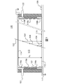
図1は、一実施形態による本発明のガス検出器の断面図を概略的に示す。 FIG. 1 schematically shows a cross-sectional view of the gas detector of the present invention according to one embodiment.
本発明のガス検出器(100)は、増幅室(A)と呼ばれる第2の室(112)からマイクログリッド(111)によりその底部において分離されたドリフト室(D)と呼ばれる少なくとも1つの第1の室(110)と、信号を取得しデータを解析および処理するための装置とのインターフェース(120、123)とを含む。 The gas detector (100) of the present invention has at least one first chamber called a drift chamber (D) separated from a second chamber (112) called an amplification chamber (A) at its bottom by a microgrid (111). Room (110) and an interface (120, 123) with a device for acquiring signals and analyzing and processing data.
ガス検出器はまた、ガスがドリフト室(110)内に流れ込ませ得るようにする拡散素子(116a、116b)を有するガス入口(121)およびガス出口(122)を含む。有利には、ガスは、所望の電界値における電子ドリフト速度を最大化するように選択される少なくとも1つの不活性化剤と共に主としてアルゴンで構成された混合ガスである。 The gas detector also includes a gas inlet (121) and a gas outlet (122) with diffusing elements (116a, 116b) that allow the gas to flow into the drift chamber (110). Advantageously, the gas is a mixed gas composed primarily of argon with at least one inactivating agent selected to maximize the electron drift rate at the desired electric field value.
図5を参照して以下に詳述されるように、検出器内に注入されるガスは、1つの好適な実施形態では、ほぼ閉回路を形成するガス再調整回路から発生する。ガス再調整回路は、ガスの質を最大化することと解析されるデータの一貫性を改善することとを目的として本発明のガス検出器の利得を直接的に濾過、制御、および安定化するという有利性を有する。 As detailed below with reference to FIG. 5, the gas injected into the detector is generated from a gas readjustment circuit that forms a nearly closed circuit in one preferred embodiment. The gas readjustment circuit directly filters, controls, and stabilizes the gain of the gas detector of the present invention with the aim of maximizing the quality of the gas and improving the consistency of the analyzed data. It has the advantage of.
ドリフト室はさらに、ドリフト室の上側部分に位置するドリフト陰極と呼ばれる平面電極(114)とアース(117)との間に結合されたバイアス回路(115a、115b)を含む。一次室の上側部分に位置する陰極は、バイアス回路が、ドリフト室内の一様な第1の電界を生成することを目的として活性化され得るようにする高電位HV1に置かれる。ドリフト室を通過するミューオン(102)からカスケードの一次電子を生成するために、バイアス回路は、ドリフト室内に、イオン化中に形成される電子−イオン対を分離するために十分に強い電界を生成する。事前定義された構成のバイアス回路のために、生成される電界は、一様であり、生成される電子(104、106、108)がマイクログリッドの面上に対し直交して投射され得るようにする。この点は、ミューオンの経路を正確に判断するために必要な測定がなされるかどうかにクリティカルである。 The drift chamber further includes a bias circuit (115a, 115b) coupled between a planar electrode (114) called a drift cathode and an earth (117) located in the upper portion of the drift chamber. The cathode, located in the upper portion of the primary chamber, is placed at a high potential HV1 that allows the bias circuit to be activated with the aim of creating a uniform first electric field in the drift chamber. To generate cascade primary electrons from muons (102) passing through the drift chamber, the bias circuit creates an electric field in the drift chamber strong enough to separate the electron-ion pairs formed during ionization. .. Due to the bias circuit of the predefined configuration, the generated electric field is uniform so that the generated electrons (104, 106, 108) can be projected orthogonally to the plane of the microgrid. do. This point is critical to whether the measurements necessary to accurately determine the muon path are made.
ミューオンの経路を解析することができるために、本発明のガス検出器のドリフト室は数センチメートルの高さ「HD」を有する。1つの好適な実施形態では、ドリフト陰極(114)とマイクログリッド(111)間の距離は約5cmである。有利には、ドリフト室の高さは、ミューオンの経路内の特定精度を得るように、そして良好な解析性能を保証するように定義される。したがって、ドリフト室の高さは以下の2つの制約を満たさなければならない、すなわち:(1)判断されるべき経路の質を高めるためにドリフト空間を最大化すること、(2)バルク的に大きく制約される区域に好適なコンパクトな限定されたセンサを得るために体積を最小化すること。 The drift chamber of the gas detector of the present invention has a height "HD" of several centimeters in order to be able to analyze the muon path. In one preferred embodiment, the distance between the drift cathode (114) and the microgrid (111) is about 5 cm. Advantageously, the height of the drift chamber is defined to obtain specific accuracy within the muon path and to ensure good analytical performance. Therefore, the height of the drift chamber must meet the following two constraints: (1) maximize the drift space to improve the quality of the path to be determined, (2) bulky. Minimize volume to obtain a compact, limited sensor suitable for confined areas.
数ミリメートルの高さのドリフト室(変換室としても知られる)を有するMicroMegas(登録商標)検出器などの既知のガス検出器とは異なり、本発明の検出器は、ドリフト室の普通でない高さのために、既知の検出器により対処されない課題を生じる。具体的には、ドリフト室の数センチメートルの高い高さは、設定され制御された一様な電界を得るために特別のバイアス手段が設けられることを必要とする。バイアス系の形状および特徴は、検出器内部の処理間のすべての複雑な相互作用(例えば、流体内のイオンの拡散およびドリフト)を、またはさらには、電界に晒される荷電粒子の経路の計算を、考慮するために、複数の物理的数値シミュレーションにより判断される。したがって、本発明のバイアス系は、ドリフト室の高さに依存する事前定義された構成を有する。バイアス回路は、1つの特別の実施形態では、ガスを非乱流的または対流的一様なやり方で拡散させるために、非常に高い(約500Mオームの)抵抗の相互接続銅トラックと小さな孔とを含むプリント回路基板の形式で生成される。さらに、バイアス回路は、特に検出器の両側の像内のアーテファクトの影響を最小化する役目を果たす。 Unlike known gas detectors such as the MicroMegas® detector, which has a drift chamber (also known as a conversion chamber) several millimeters high, the detectors of the present invention have an unusual height of the drift chamber. Because of this, it creates challenges that are not addressed by known detectors. Specifically, the high height of a few centimeters of the drift chamber requires that special biasing means be provided to obtain a set and controlled uniform electric field. The shape and characteristics of the bias system can be used to calculate all complex interactions between processes inside the detector (eg, diffusion and drift of ions in a fluid), or even the path of charged particles exposed to an electric field. , Judged by multiple physical numerical simulations to take into account. Therefore, the bias system of the present invention has a predefined configuration that depends on the height of the drift chamber. Bias circuits, in one particular embodiment, with very high resistance (about 500 ohms) interconnected copper tracks and small holes to diffuse the gas in a uniform, non-turbulent or convective manner. Is generated in the form of a printed circuit board containing. In addition, the bias circuitry serves to minimize the effects of artifacts in the image, especially on both sides of the detector.
1つの好適な実施形態では、ドリフト陰極(114)は約−3,000Vの負電位にされ、マイクログリッド(111)は抵抗器(121)によりアースされ、約500V/cmの電界がドリフト室内で生成され得るようにする。 In one preferred embodiment, the drift cathode (114) is brought to a negative potential of about -3,000 V, the microgrid (111) is grounded by a resistor (121), and an electric field of about 500 V / cm is applied in the drift chamber. Allow it to be generated.
図2は、図1のガス検出器の増幅室(112)の断面図を示す。増幅室は、マイクログリッド(111)と抵抗性保護手段である電極(113)(抵抗性陽極と呼ばれる)との間に画定される。設定された伝導率(0.5〜5MΩ/cm)を有する抵抗性電極は、事前定義されたテンプレートに従って編成される導電性トラックまたはストリップのメッシュで構成される。マイクログリッド内の孔を通過する一次電子(106)はアバランシェ効果(107)が生成されるまで加速される。ストリップの配置(x,y)は、測定可能電気信号が、信号取得装置(120)の従来の電子計器により収集され得るようにする。 FIG. 2 shows a cross-sectional view of the amplification chamber (112) of the gas detector of FIG. The amplification chamber is defined between the microgrid (111) and the electrode (113), which is a resistance protective means (called a resistance anode). Resistive electrodes with set conductivity (0.5-5 MΩ / cm) consist of a mesh of conductive tracks or strips knitted according to a predefined template. The primary electrons (106) passing through the pores in the microgrid are accelerated until the avalanche effect (107) is generated. The strip arrangement (x, y) allows measurable electrical signals to be collected by conventional electronic meters in the signal acquisition device (120).
図1と図2に示された検出器では、導電性読み取りストリップ(118x,118y)は、どれだけトラックが抵抗層に近いかに応じて変化する幅の銅トラックであり、その結果、誘起電気信号は様々なレベル間で可能な限り一様である。したがって、抵抗性陽極に近いトラックはこの陽極から遠いトラックより小さな寸法を有しなくてはならない。これらのトラックは、前記抵抗層によりスパークから保護され、垂直「x」および「y」軸に沿って分散される。導電性トラックのこの分散は、これらのトラック内で誘起される電気的パルスの解析を介し、位置が2次元で判断され得るようにする。一実施形態では、メッシュは、例えば「x」軸上の1024個のトラックと「y」軸上の512個のトラックとを含み得る。 In the detectors shown in FIGS. 1 and 2, the conductive reading strip (118x, 118y) is a copper track with a width that varies depending on how close the track is to the resistance layer, resulting in an induced electrical signal. Is as uniform as possible between the various levels. Therefore, a track closer to the resistive anode must have smaller dimensions than a track farther from this anode. These tracks are protected from sparks by the resistance layer and are dispersed along the vertical "x" and "y" axes. This dispersion of conductive tracks allows the position to be determined in two dimensions through analysis of the electrical pulses induced within these tracks. In one embodiment, the mesh may include, for example, 1024 tracks on the "x" axis and 512 tracks on the "y" axis.
抵抗層の導電ストリップは、ドリフト室の陰極の電位「HV1」よりはるかに低い電位「HV2」にされる。1つの好適な実施形態では、電位「HV2」は、約50kV/cmの電界が増幅室内で生成され得るようにする約500Vである。HV1の値は一次電子のドリフト速度を最適化するように選択される。第2の電界の値HV2は、検出器の利得が調整され得るようにする。しかし、2つの値は、2つの電界の比が、第2の室に向かってマイクログリッドを通過することができる(これは「電子透明性」としても知られる)ようになる一次電子の数に影響を与えるので、独立ではない。劣悪な電子透明性値は測定有効性を低下させる。 The conductive strip of the resistance layer is set to a potential "HV2" much lower than the potential "HV1" of the cathode of the drift chamber. In one preferred embodiment, the potential "HV2" is about 500 V, which allows an electric field of about 50 kV / cm to be generated in the amplification chamber. The value of HV1 is selected to optimize the drift rate of the primary electrons. The value HV2 of the second electric field allows the gain of the detector to be adjusted. However, the two values are the number of primary electrons that allow the ratio of the two electric fields to pass through the microgrid towards the second chamber (also known as "electron transparency"). It is not independent because it affects. Poor electron transparency values reduce measurement effectiveness.
加えて、第2の室(増幅区域)内で生成された電界と第1の室(ドリフト室)内で生成された電界との比は、使用されるガスに依存する。上記比は、少なくとも10より高く、好適には約50である。 In addition, the ratio of the electric field generated in the second chamber (amplification zone) to the electric field generated in the first chamber (drift chamber) depends on the gas used. The ratio is at least greater than 10, preferably about 50.
増幅室はドリフト室の高さ「HD」より非常に低い高さ「HA」を有する。1つの好適な実施形態では、マイクログリッド(111)と抵抗層(113)間の距離は約100マイクロメートルである。 The amplification chamber has a height "HA" that is much lower than the height "HD" of the drift chamber. In one preferred embodiment, the distance between the microgrid (111) and the resistance layer (113) is about 100 micrometers.
柱(119)は通常、マイクログリッドを支持するために読み取り電極の表面全体にわたって分散され、その全長にわたって抵抗性電極から設定距離に保たれ得るようにする。支持柱は、マイクログリッドと抵抗層が電気的に絶縁され一定距離に維持され得るようにする誘電体で作られる。柱の径は、検出が可能でない不感帯を制限するために可能な限り小さくなければならない。 The columns (119) are typically dispersed over the surface of the reading electrode to support the microgrid so that it can be kept at a set distance from the resistant electrode over its entire length. The support column is made of a dielectric that allows the microgrid and resistance layer to be electrically insulated and maintained at a constant distance. The diameter of the column should be as small as possible to limit the dead zones that cannot be detected.
図3は、本発明の検出器を通過する電離粒子の束の様々な状態を示す。単純化のために、図3は、ミューオンなどの1つの粒子が検出器を通過すると何が発生するかを示すが、原理はミューオンの束に関し同じままである。本発明の原理は、ドリフト室を通る荷電粒子(302)の通路上のガスのイオン化に基づく。その通路上では、ミューオンは、ドリフト室を貫流するガスをイオン化し、一次電子と呼ばれるものを生成する(304)。ドリフト室内に存在する電界に晒される生成された一次電子は、ドリフト室に対し直交するマイクログリッドまでドリフトする(306)。マイクログリッドは増幅室への遷移の区域である(308)。マイクログリッド内の孔を通過した一次電子は次に、アバランシェ効果を介し、増幅室内に存在する電界により増倍される(310)。二次電子と呼ばれるものとイオンとのマイクロアバランシェは、抵抗層内に電流を誘起し(312)、これにより、容量結合を介し下方の導電性読み取りトラック(x,y)内に電気信号を誘起する(314)。信号の解析は、粒子の通過に伴うインパクトのニ次元位置(x,y)と到達時刻とが判断され得るようにする。すべての電気信号は次に、取得および処理回路により処理される(120)。信号は最初に増幅される(316)。1つの好適な実施形態では、増幅器は、周知のAPV25タイプのハイブリッド基板の回路である。アナログ信号はその後、アナログ/ディジタル変換器によりディジタル化され(318)、ディジタルデータは次に、コンピュータにより処理されることができるように、適応化され(320)格納される(324)。 FIG. 3 shows various states of a bundle of ionized particles passing through the detector of the present invention. For simplicity, FIG. 3 shows what happens when a single particle, such as a muon, passes through the detector, but the principle remains the same for bundles of muons. The principle of the present invention is based on the ionization of gas on the passage of charged particles (302) through the drift chamber. On that passage, muons ionize the gas flowing through the drift chamber, producing what are called primary electrons (304). The generated primary electrons exposed to the electric field existing in the drift chamber drift to the microgrid orthogonal to the drift chamber (306). The microgrid is the area of transition to the amplification chamber (308). The primary electrons that have passed through the pores in the microgrid are then multiplied by the electric field present in the amplification chamber via the avalanche effect (310). A microavalanche of what is called a secondary electron and an ion induces a current in the resistance layer (312), thereby inducing an electrical signal into the lower conductive reading track (x, y) via capacitive coupling. (314). The analysis of the signal makes it possible to determine the two-dimensional position (x, y) and the arrival time of the impact due to the passage of the particle. All electrical signals are then processed by the acquisition and processing circuits (120). The signal is amplified first (316). In one preferred embodiment, the amplifier is a well-known APV25 type hybrid board circuit. The analog signal is then digitized by an analog-to-digital converter (318), and the digital data is then adapted (320) and stored (324) so that it can be processed by a computer.
増幅室内で生成されたアバランシェ効果(310)は、同一であるが反対極性のパルスをグリッド上に生成する(311)。本発明の検出器のデータ解析およびデータ処理装置は、この信号が、検出器を通る電離粒子の通過に関する情報を提供するために使用され得るようにする。これらの誘起電気信号は最初に増幅され(313)、次に、背景雑音を除去するために識別され(315)、次に、論理パルスへ変換される(317)。1つの好適な実施形態では、生成されたパルスは、周知の標準化「原子力計装モジュール:Nuclear Instrumentation Module」(NIM)フォーマットのものである。このNIMパルスは、電離粒子の通過の精密な時刻を排他的に捕捉することを可能にすることを目的としてデータの取得をトリガする役目を果たす。これは、取得されたデータ容量が、像の復元に対して興味無いデータを除去することにより最適化され得るようにする。有利には、検出器の有効性は、設定されたサンプリング周波数による取得に関係するデータ損失が例えば最小化されるので、これにより改善される(具体的には、電子基板は、サンプル間の不感時間のために、連続記録には好適ではない)。 The avalanche effect (310) generated in the amplification chamber produces pulses of the same but opposite polarity on the grid (311). The detector data analysis and data processing apparatus of the present invention allows this signal to be used to provide information about the passage of ionized particles through the detector. These induced electrical signals are first amplified (313), then identified to remove background noise (315), and then converted into logical pulses (317). In one preferred embodiment, the generated pulses are of the well-known standardized "Nuclear Instrumentation Module" (NIM) format. This NIM pulse serves to trigger the acquisition of data for the purpose of making it possible to exclusively capture the precise time of passage of the ionized particles. This allows the acquired data capacity to be optimized by removing data that is not of interest to image restoration. Advantageously, the effectiveness of the detector is improved by, for example, the data loss associated with acquisition at the set sampling frequency is minimized (specifically, the electronic substrate is insensitive between samples). Not suitable for continuous recording due to time).
データ取得およびデータ処理回路のすべては有利には、本発明の検出器の唯一のインターフェース(120)を形成する単一電子基板上に位置し得る。 All of the data acquisition and data processing circuits can advantageously be located on a single electronic substrate forming the only interface (120) of the detector of the present invention.
一実施形態(不図示)では、例えばシンチレータベースである外部データ取得装置が、電離粒子の経路の解析のためのデータの取得をトリガするために追加され得る。 In one embodiment (not shown), for example, a scintillator-based external data acquisition device may be added to trigger the acquisition of data for analysis of the path of ionized particles.
図4は、電離粒子の経路の再構築を目的として行われるデータ解析の工程の流れ図を示す。照射された画素の位置から2D位置を直接判断するために正方行列アレイの画素を採用する非特許文献“Operation of a GEM−TPC with Pixel Readout”by Brezina et al.,IEEE Transactions on Nuclear Science,Vol.59,no.6,1 December 2012に記載のGEM−TPC検出器とは異なり、本発明の原理は、90°だけオフセットされた2つの軸に沿って存在する照射されたトラックの組み合わせを使用することにより精密な2D位置を計算することである。 FIG. 4 shows a flow chart of a data analysis process performed for the purpose of reconstructing the path of ionized particles. Non-patent document "Operation of a GEM-TPC with Pixel Readout" by Brezina et al., Which employs square matrix array pixels to directly determine the 2D position from the position of the irradiated pixels. , IEEE Transitions on Nuclear Science, Vol. 59, no. Unlike the GEM-TPC detectors described in 6,1 December 2012, the principles of the present invention are precise by using a combination of illuminated tracks that exist along two axes offset by 90 °. It is to calculate the 2D position.
検出器(120)のインターフェースへ接続されたハイブリッド基板上で開始される方法(316)は、所与の期間内に生成された電気信号の電圧振幅の等時間間隔の測定により始まる。1つの特定実施形態では、それぞれが128個の読み取りトラック(x,y)の測定に専用化された各ハイブリッド基板は、67.5μsの間、電圧を25ナノ秒毎に測定する。 The method (316), which is initiated on a hybrid substrate connected to the interface of the detector (120), begins with the measurement of the voltage amplitude of the electrical signal generated within a given period at equal time intervals. In one particular embodiment, each hybrid substrate, each dedicated to measuring 128 read tracks (x, y), measures the voltage every 25 nanoseconds for 67.5 μs.
測定電圧が所与の閾値未満であれば(404、「いいえ」分岐)、測定は雑音であると考えられる(406)。測定された平均電圧が所与の閾値より高ければ(404、「はい」分岐)、測定は読み取りトラックへのインパクトを表すと考えられ、保持される(408)。通常、閾値は20,000個の電子上の電荷に等価である。 If the measured voltage is below a given threshold (404, "no" branch), the measurement is considered noise (406). If the measured average voltage is higher than a given threshold (404, "yes" branch), the measurement is considered to represent the impact on the read track and is retained (408). Usually, the threshold is equivalent to the charge on 20,000 electrons.
本方法は次に、各ハイブリッド基板により示されたインパクトが読み取りトラックに対して直近のインパクトであるかどうかが判断され得るようにする(410)。上記インパクトが、分離された読み取りトラックに対応すれば、分離されたインパクトであると考えられ、雑音として拒絶される(412)。インパクトが連続的読み取りトラック(例えば10個の連続的トラック)に対応すれば、本方法は、インパクトを受けたトラックが「x」軸と「y」軸とに沿ってグループ化され得るようにする(414)。 The method then allows it to be determined whether the impact exhibited by each hybrid substrate is the most recent impact on the read track (410). If the impact corresponds to a separated read track, it is considered to be a separated impact and is rejected as noise (412). If the impact corresponds to a continuous read track (eg 10 continuous tracks), the method allows the impacted tracks to be grouped along the "x" and "y" axes. (414).
以下の工程(416)では、本方法は、各軸「x」と「y」とに沿ったどのグループのトラックが所与の時間窓内にインパクトを受けるかを判断することと、それらを関連付けることとを可能にする。トラック(x,y)のグループ同士の関連性は、粒子の位置に関する情報を提供する点を判断し(418)、したがって、この点に対応する粒子がドリフト室を通過した高さを判断し、これにより、その経路が再構築され得るようにする。有利には、本方法は、粒子がドリフト室内に侵入した入射角に応じて点が識別され得るようにする。 In the following step (416), the method associates them with determining which group of tracks along each axis "x" and "y" will be impacted within a given time window. Make things possible. The relevance between the groups of tracks (x, y) determines the point that provides information about the position of the particles (418), and thus determines the height at which the particles corresponding to this point have passed through the drift chamber. This allows the route to be reconstructed. Advantageously, the method allows the points to be identified according to the angle of incidence at which the particles have entered the drift chamber.
具体的には、検出器内にほぼ垂直に侵入する粒子に関して、増幅室内の二次電子のマイクロアバランシェは極密集しており、重なり得る。第1の処理操作(420)は、垂直軸に対する入射角がほぼ零である点(20°未満の角度(+10°〜−10°の角度範囲)で検出器の室内に侵入した粒子に対応する)へ適用される。これらの粒子に関して、近隣トラックのグループのすべては単一グループであると考えられ、本方法は、測定の期間にわたるこのグループ内の重心の動きが解析され得るようにする。本方法は次に、粒子の方位経路が、重心の動きの方向と点の位置(x,y)とに基づき再構築され得るようにする(422)。 Specifically, with respect to particles that enter the detector almost vertically, the microavalanches of secondary electrons in the amplification chamber are extremely dense and can overlap. The first processing operation (420) corresponds to particles that have entered the detector chamber at an angle of less than 20 ° (angle range of + 10 ° to -10 °) where the angle of incidence with respect to the vertical axis is near zero. ) Applies to. For these particles, all of the groups of neighboring tracks are considered to be a single group, and the method allows the movement of the center of gravity within this group to be analyzed over the duration of the measurement. The method then allows the directional path of the particles to be reconstructed based on the direction of movement of the center of gravity and the position of the point (x, y) (422).
20°〜90°の間に含まれる角度範囲内に存在する非零角度で検出器内に侵入する粒子に関して、第2の処理操作が適用される(424)。これらの粒子に関して、ドリフト室を通る粒子の通過中に生成された二次電子の様々なマイクロアバランシェが、明瞭に分離されて異なるトラックのグループにインパクトを与える。本方法は、トラックの各グループが、トラックのグループの動きの変動を判断することを目的として測定の期間にわたって解析され得るようにする(424)。本方法は次に、粒子の方位経路が、トラックのグループの動きの方向と点の位置(x,y)とに基づき再構築され得るようにする(426)。 A second processing operation is applied to particles that enter the detector at non-zero angles that are within the angular range included between 20 ° and 90 ° (424). For these particles, the various microavalanches of secondary electrons generated during the passage of the particles through the drift chamber are clearly separated and impact different groups of tracks. The method allows each group of tracks to be analyzed over a period of measurement for the purpose of determining the variation in movement of the group of tracks (424). The method then allows the directional path of the particles to be reconstructed based on the direction of movement of the group of tracks and the position of the points (x, y) (426).
2つの先行ケースでは、方位経路が知られると、3Dでの経路の計算が、各粒子の天頂角の獲得と共に行われる。一次および二次電子のドリフト速度と移動時間(電気信号間の分離間隔により与えられる)とを知ると、本方法は、移動される垂直方向距離としたがって各経路の天頂角とを再構築することができる。 In the two preceding cases, once the azimuth path is known, the path calculation in 3D is done with the acquisition of the zenith angle of each particle. Knowing the drift velocity and travel time of primary and secondary electrons (given by the separation interval between electrical signals), the method reconstructs the vertical distance traveled and therefore the zenith angle of each path. Can be done.
最後に、天頂および方位角に応じて測定されたミューオンの束に基づき、通過された媒体の密度を撮像することが可能になる。具体的には、ミューオン束の減衰は、表面ミューオン束と媒体(例えば岩盤、芸術作品、産業用大建造物)を通過後に測定されたミューオン束との比として定義される。このパラメータは、その平均密度が掛けられた通過された物資の長さに、既知の数学的関係により関係付けられる。 Finally, it becomes possible to image the density of the passed medium based on the bundle of muons measured according to the zenith and azimuth. Specifically, the decay of muon bundles is defined as the ratio of the surface muon bundles to the muon bundles measured after passing through a medium (eg, bedrock, work of art, large industrial building). This parameter is related to the length of the passed material multiplied by its average density by a known mathematical relationship.
撮像対象媒体の表面の幾何学形状の知識は、検出器に到達する前にミューオンにより通過された長さが判断され得るようにする。当業者は「共通源から発生するミューオンの数と束との比が、設定されたサイズの検出器によるミューオンの数とそれらの精密な到達時刻との測定のおかげで計算され、これにより、ある方向から発生するミューオン束(単位面積および時間当たりの粒子の数)が取得され得るようにする」ということを知っている。既知の寸法を有する物体の密度は、次の周知の式により表されるように、自由空間(free−sky)ミューオン束と測定された束との比に比例する:I/I0=exp(μ×d)、ここで、I0は表面束、μは密度関連減衰係数、dは粒子が通過した距離である。表面束I0は、以下のモデルなどの高度、緯度および経度を含むパラメータに応じてミューオン束値を予測することができる理論モデルのおかげで判断される:
[1]T.K.Gaisser,Cosmic Rays and Particle Physics.Cambridge,1990;
[2]L.N.Bogdanova,M.G.Gavrilov,V.N.Kornoukhov and A.S.Starostin,submitted to Phys.Atom.Nucl.[arXiv:nucl−ex/0601019];
[3]A.Tang,G.Horton−Smith,V.A.Kudryavtsev and A.Tonazzo,submitted to Phys.Rev.E[arXiv:hep−ph/0604078]。
Knowledge of the geometry of the surface of the medium to be imaged allows the length passed by the muon to be determined before reaching the detector. Those skilled in the art will say, "The ratio of the number of muons originating from a common source to the bundle is calculated thanks to the measurement of the number of muons and their precise arrival time by a detector of a set size. Allows muon bundles (number of particles per unit area and time) generated from a direction to be obtained. " The density of an object with known dimensions is proportional to the ratio of the free space (free-sky) muon bundle to the measured bundle, as expressed by the following well-known equation: I / I 0 = exp ( μ × d), where I 0 is the surface bundle, μ is the density-related damping coefficient, and d is the distance the particle has passed. The surface bundle I 0 is judged thanks to a theoretical model that can predict the muon bundle value according to parameters including altitude, latitude and longitude, such as the following models:
[1] T.I. K. Gaisser, Cosmic Rays and Particle Physics. Cambridge, 1990;
[2] L. N. Bogdanova, M.D. G. Gavrilov, V.I. N. Kornoukhof and A. S. Starostin, submitted to Phys. Atom. Nucl. [ArXiv: nucl-ex / 06001019];
[3] A. Tang, G.M. Horton-Smith, V.I. A. Kudryavtsev and A. Tonazo, submitted to Phys. Rev. E [arXiv: hep-ph / 0604078].
表面束Iの測定は次に、粒子の経路に沿った平均密度「d」が導出され得るようにする。したがって、トポグラフィーに関連する指向性ミューオン束の減衰の測定は、方位角と天頂角に応じて媒体の平均密度が取得され得るようにする。 The measurement of the surface bundle I then allows the average density "d" along the particle path to be derived. Therefore, the measurement of the attenuation of the directional muon flux associated with topography allows the average density of the medium to be obtained depending on the azimuth and zenith angles.
図5は、ガス検出器内のガスの分布および質を制御および調整する方法を示す。ガス検出器の既知のガス分配回路は、開回路モードで動作し、これは、ガスの多大な損失と環境の不必要な汚染の危険性とを生じる。さらに、ガス検出器の性能はとりわけ、使用されるガスの質と安定性とに依存する。新しいガス検出器ガス分散装置と関連方法とが提供される。有利には、本装置は、ガス消費が、検出器の性能を低下することなく低下され得るようにするほぼ閉じた回路である。本装置は、ガス中に存在する様々な汚染物を濾過する系であって、ガスの流速を制御するための回路と環境変数(特に、ガス検出器の内圧と温度)を制御するための回路とを伴う系で構成される。有利には、本装置を構築する様々な素子の組み合わせは、ガス検出器の利得が直接制御および安定化され得るようにし、したがって、一貫したデータが、粒子の軌道を確立することを目的として取得され得るようにする。さらに、ガス分散回路は閉回路モードで動作するので、ガス放射は低減される。これは、劣悪換気限定空間において有利でありかつ必要である。 FIG. 5 shows a method of controlling and adjusting the distribution and quality of gas in a gas detector. The known gas distribution circuit of the gas detector operates in open circuit mode, which results in significant loss of gas and the risk of unnecessary pollution of the environment. Moreover, the performance of the gas detector depends, among other things, on the quality and stability of the gas used. A new gas detector, a gas disperser, and related methods are provided. Advantageously, the device is a nearly closed circuit that allows gas consumption to be reduced without compromising detector performance. This device is a system that filters various contaminants existing in the gas, and is a circuit for controlling the flow velocity of the gas and a circuit for controlling the environmental variables (particularly, the internal pressure and temperature of the gas detector). It is composed of a system with and. Advantageously, the combination of various elements that make up the device allows the gain of the gas detector to be directly controlled and stabilized, thus obtaining consistent data for the purpose of establishing particle trajectories. To be able to be. In addition, the gas dispersion circuit operates in closed circuit mode, which reduces gas radiation. This is advantageous and necessary in poorly ventilated limited spaces.
図5は、閉回路内のガス流(二重矢印)と、同回路内の様々な測定点において観測されるデータ流れ(単一矢印)とを示す。図6は、このようなガス分散装置の実施形態を示し、この実施形態は本発明のガス検出器に特に好適である。明確化のために、データ流れは図6に示さない。 FIG. 5 shows a gas flow (double arrow) in a closed circuit and a data flow (single arrow) observed at various measurement points in the circuit. FIG. 6 shows an embodiment of such a gas disperser, which embodiment is particularly suitable for the gas detector of the present invention. For clarity, the data flow is not shown in FIG.
ガスを制御および調整する方法(500)は、回路の入口内へのガスの注入で始まる(502)。図6に示すように、ガスは高圧ガスシリンダ(600)から発生し得、ガスはシリンダから出ると、圧力を規定値(好適には、室内圧力より最大0.1bar高い)にするように圧力調整器(601)を通過する。次に、ガスは粒子フィルタ(602)を通って濾過される。濾過は、粒子を浮遊状態に保つことにより検出器の内部の汚染が回避され得るようにする。好適な実施形態では、フィルタは、検出器のマイクログリッドの孔の大きさ未満の値である0.22マイクロメートルの粒子フィルタである。次に、ガスは、ガスの流量が手動で制御され得るようにする可変面積流量計(603)を通って閉回路中に送出される。 The method of controlling and adjusting the gas (500) begins with the injection of the gas into the inlet of the circuit (502). As shown in FIG. 6, the gas can be generated from the high pressure gas cylinder (600), and when the gas exits the cylinder, it is pressured to bring the pressure to a specified value (preferably up to 0.1 bar above the room pressure). It passes through the regulator (601). The gas is then filtered through a particle filter (602). Filtration allows contamination inside the detector to be avoided by keeping the particles suspended. In a preferred embodiment, the filter is a 0.22 micrometer particle filter that is less than the size of the pores in the detector's microgrid. The gas is then delivered into the closed circuit through a variable area flow meter (603) that allows the flow rate of the gas to be controlled manually.
この流量は、閉回路の入口においてディジタル的に測定され(504、604)、測定結果はPLC(540)へ送信される。次に、ガスは、ガスを流れるように強いるために、圧力勾配が生成され得るようにする可変速度ポンプ(506、606)へ送られる。次に、ガスは任意選択的に、水蒸気用の第2のフィルタ(510、610)が後に続く酸素を保持する第1のフィルタ(508、608)内で濾過され得る、または、酸素および水蒸気フィルタにより自由にされた不純物のために必要とされ得る第2の粒子フィルタ(512、612)へ直接送られ得る、のいずれかである。好適な実施形態では、粒子フィルタは0.22マイクロメートル粒子フィルタである。 This flow rate is digitally measured at the inlet of the closed circuit (504, 604) and the measurement result is transmitted to the PLC (540). The gas is then sent to a variable velocity pump (506, 606) that allows a pressure gradient to be generated in order to force the gas to flow. The gas can then optionally be filtered in a first filter (508, 608) that retains oxygen followed by a second filter for water vapor (510, 610), or an oxygen and water vapor filter. Either can be sent directly to a second particle filter (512, 612), which may be needed for impurities freed by. In a preferred embodiment, the particle filter is a 0.22 micrometer particle filter.
酸素フィルタは、この分子による一次電子の吸収を最小化する役目を果たし、これにより検出器の性能を高める。 The oxygen filter serves to minimize the absorption of primary electrons by this molecule, thereby enhancing the performance of the detector.
水フィルタは、一方では前述のフィルタと同じ理由で、他方では、検出器の利得を著しく低下させ、その腐食を促進するので、水蒸気がドリフト室へ到達するのを防止することができるようにする。 Water filters, on the one hand, for the same reasons as the filters described above, on the other hand, significantly reduce the gain of the detector and promote its corrosion, thus allowing water vapor to be prevented from reaching the drift chamber. ..
粒子フィルタ(512、612)を出ると、ガスの圧力が測定され、その値はPLC(510)へ送信される。次に、ガスは検出器(100)に入る。 Upon exiting the particle filter (512, 612), the pressure of the gas is measured and the value is transmitted to the PLC (510). The gas then enters the detector (100).
検出器を出ると、所望の動作圧にされた反戻り弁(516、616)は、ガスの圧力が、ガスの放出を可能にすることと、系を過剰圧力から保護することとを目的として、試験され得るようにする(518)。上記放出は、空気のいかなる侵入も防止し、出るガス流が見られ得るようにする気泡管(526、626)内へ行われる。 Upon exiting the detector, return valves (516, 616) at the desired operating pressure are intended to allow the pressure of the gas to release the gas and to protect the system from overpressure. , To be tested (518). The release is made into a bubble tube (526, 626) that prevents any ingress of air and allows the outflow of gas to be seen.
検出器(100)を出たガス流は測定され(520、620)、再循環中のガスの量が判断され得るようにする。測定値はPLC(510)へ送信される。次に、ガスは、ガスの戻りが防止され得るようにするとともに流れを単一方向に強いる制御弁(522、622)へ移る。 The gas flow exiting the detector (100) is measured (520, 620) so that the amount of gas in recirculation can be determined. The measured value is transmitted to the PLC (510). The gas is then transferred to control valves (522, 622) that force the flow in one direction while allowing the return of the gas to be prevented.
次に、ガスは流れて入力ポンプ(506、606)へ戻る。 The gas then flows back to the input pumps (506, 606).
PLC(510)は、ガスの流量の測定結果(504、520)、閉回路において観察された圧力の測定結果(514)、およびこの目的のために設置された熱電対からの温度情報(527)を受信し、次にガスの流量を調整することができる(538)。 The PLC (510) is a gas flow measurement result (504,520), a pressure measurement result observed in a closed circuit (514), and temperature information from a thermocouple installed for this purpose (527). Can then be adjusted for gas flow rate (538).
ガスの流速を制御するための回路は、検出器の利得が所望の値に維持され得るようにする。検出器の利得は、検出器から受信されたデータ(530)を使用することにより、調整可能時間間隔(典型的には1h)で定期的に計算され、ユーザにより指定された最適値(532)と比較される。処理ユニット(534)は検出器の利得が判断され得るようにし、この値は事前定義された最適利得値と比較される(536)。これらの値に差異がある場合、回路は、調整(538)が規定流量に対し行われ得るようにし、値がPLC(540)へ送信され得るようにし、ポンプ(506)の速度が自動的に修正され得るようにし、これにより、ガスの流量を調整し、最適利得値が戻され得るようにする。 The circuit for controlling the flow rate of the gas allows the gain of the detector to be maintained at the desired value. The gain of the detector is calculated periodically at adjustable time intervals (typically 1h) by using the data received from the detector (530) and is the optimum value specified by the user (532). Is compared with. The processing unit (534) allows the gain of the detector to be determined and this value is compared to the predefined optimum gain value (536). If there is a difference between these values, the circuit allows the adjustment (538) to be made for the specified flow rate, the value can be sent to the PLC (540), and the speed of the pump (506) is automatically Allows it to be modified, thereby adjusting the flow rate of the gas so that the optimum gain value can be returned.
オペレータにPLC(505)を手動で制御することを許容する別の代替動作モードが存在する。 There is another alternative mode of operation that allows the operator to manually control the PLC (505).
したがって、閉回路モードで動作する提案されたガス検出器ガス分散装置は、ガスの濾過の効果、濾過されたガスの再循環の効果、測定を介した検出器の利得の直接制御の効果、および検出器の内圧などの動作パラメータの適応化の効果を組み合わせる。 Therefore, the proposed gas detector gas disperser operating in closed circuit mode has the effect of filtering the gas, the effect of recirculating the filtered gas, the effect of direct control of the gain of the detector through measurement, and Combine the effects of adapting operating parameters such as the internal pressure of the detector.
当業者は、変更が本発明の原理から乖離することなく、説明した好適な実施形態に対して行われ得るということを理解することになる。 Those skilled in the art will appreciate that modifications can be made to the preferred embodiments described without departing from the principles of the invention.
Claims (15)
一次電子が生成されることを可能にする第1のドリフト室と、マイクログリッドにより前記第1の室から切り離された第2の増幅室とを有するガス検出器と、
電離粒子経路の計算結果を前記撮像対象物質の体積密度に関する情報に変換するために前記ガス検出器へ結合された計算手段とを含み、前記装置は、
閉回路として動作する、前記検出器内にガスを注入するためのガス分散回路が、前記第1のドリフト室に結合され、前記ガス分散回路は、前記検出器の利得を所望の値に維持するように、前記ガスの流速を制御して前記ガスの流量を調整する手段を含み、
前記第1のドリフト室は、前記一次電子の、前記マイクログリッドにより画定された面の直交した投射を得るために、前記第1の室内で、一様、一定、および制御された電界を得るように数値シミュレーションにより形状および特徴が判断される第1のバイアス手段を含む、ことを特徴とし、
前記計算手段が、
− 検出器を通る電離粒子の束を検出し、
− 前記第1の室において各電離粒子の経路に沿って生成された一次電子のアバランシェ効果から生じ、前記第1の室に直交した前記マイクログリッドを通る前記第2の室における二次電子の、直交(x、y)読み取りトラック上でのインパクトに対応する増幅された電気信号の電圧振幅を、所与の期間の間に測定し、
− 同じ時間窓においてインパクトを受けた連続的読み取りトラックのグループを構築し、
− 読み取りトラックの各グループに対して、前記グループに対して測定された前記電気信号の解析から、インパクト点の二次元位置(x、y)および到達時刻を計算し、
− 読み取りトラックの各グループに対して、前記グループの前記インパクト点の位置および時間情報から、電離粒子の方位角および天頂角の軌道を計算し、
− すべての電離粒子の、すべての方位角および天頂角の軌道から、前記所与の期間に対する撮像対象物質の体積密度に関する情報を計算するように構成されている、ことを特徴とする装置。 An apparatus for determining a body Sekimitsu of the imaging target substance,
A gas detector having a first drift chamber that allows the generation of primary electrons and a second amplification chamber that is separated from the first chamber by a microgrid .
The calculation results of the ionizing particle path and a calculating means coupled to said gas detector in order to convert the information on the body Sekimitsu degree of the imaging target material, before KiSo location is
A gas dispersion circuit for injecting gas into the detector, which operates as a closed circuit, is coupled to the first drift chamber, and the gas dispersion circuit maintains the gain of the detector at a desired value. As such, a means for controlling the flow velocity of the gas to adjust the flow rate of the gas is included.
The first drift chamber, the primary electrons, in order to obtain the orthogonal projection of the plane defined by the microgrid, before Symbol first chamber, uniform, constant, and controlled electric field It is characterized by including a first biasing means whose shape and features are determined by numerical simulation so as to obtain .
The calculation means
− Detects a bundle of ionized particles passing through the detector
− Of the secondary electrons in the second chamber, which arise from the avalanche effect of the primary electrons generated along the path of each ionized particle in the first chamber and pass through the microgrid orthogonal to the first chamber. The voltage amplitude of the amplified electrical signal corresponding to the impact on the orthogonal (x, y) read track is measured over a given period of time.
− Build a group of impacted continuous read tracks in the same time window,
-For each group of read tracks, the two-dimensional position (x, y) and arrival time of the impact point are calculated from the analysis of the electrical signal measured for the group.
-For each group of reading tracks, the orbits of the azimuth and zenith angles of the ionized particles are calculated from the position and time information of the impact point of the group.
-A device characterized in that it is configured to calculate information about the volume density of the material to be imaged for the given period from the orbits of all azimuths and zeniths of all ionized particles.
− 検出器を通過する電離粒子の束を検出し、前記検出器が請求項1〜13のいずれか一項に記載のガス検出器である、工程と、
− 前記第1の室において各電離粒子の経路に沿って生成された一次電子のアバランシェ効果から生じ、前記第1の室に直交した前記マイクログリッドを通る前記第2の室における二次電子の、直交(x、y)読み取りトラック上でのインパクトに対応する増幅された電気信号の電圧振幅を、所与の期間の間に測定する、工程と、
− 同じ時間窓においてインパクトを受けた連続的読み取りトラックのグループを構築する、工程と、
− 読み取りトラックの各グループに対して、前記グループに対して測定された前記電気信号の解析から、インパクト点の二次元位置(x、y)および到達時刻を計算する、工程と、
− 読み取りトラックの各グループに対して、前記グループの前記インパクト点の位置および時間情報から、電離粒子の方位角および天頂角の軌道を計算する、工程と、
− すべての電離粒子の、すべての方位角および天頂角の軌道から、前記所与の期間に対する撮像対象物質の体積密度に関する情報を計算する、工程とを含む方法。 A method for determining a body Sekimitsu of the imaging target substance,
- detecting the flux of ionizing particles passing through the detector, the detector is a gas detector according to any one of claims 1 to 13 and a step,
− Of the secondary electrons in the second chamber, which arise from the avalanche effect of the primary electrons generated along the path of each ionized particle in the first chamber and pass through the microgrid orthogonal to the first chamber. A process of measuring the voltage amplitude of an amplified electrical signal corresponding to an impact on an orthogonal (x, y) read track over a given period of time.
− The process of building a group of impacted continuous read tracks in the same time window,
-For each group of read tracks, the process of calculating the two-dimensional position (x, y) and arrival time of the impact point from the analysis of the electrical signal measured for that group,
-For each group of reading tracks, the process of calculating the azimuth and zenith angle trajectories of the ionized particles from the position and time information of the impact point of the group.
-A method comprising the step of calculating information about the volume density of the material to be imaged for the given period from the orbits of all azimuths and zeniths of all ionized particles.
Applications Claiming Priority (3)
| Application Number | Priority Date | Filing Date | Title |
|---|---|---|---|
| FR1654188 | 2016-05-11 | ||
| FR1654188A FR3051258B1 (en) | 2016-05-11 | 2016-05-11 | METHOD AND DEVICE FOR DETERMINING THE DENSITY OF ROCKY VOLUMES OR ARTIFICIAL BUILDINGS |
| PCT/EP2017/061262 WO2017194647A1 (en) | 2016-05-11 | 2017-05-11 | Method and device for determining the density of rocky volumes or artificial buildings |
Publications (2)
| Publication Number | Publication Date |
|---|---|
| JP2019522803A JP2019522803A (en) | 2019-08-15 |
| JP6955552B2 true JP6955552B2 (en) | 2021-10-27 |
Family
ID=57136960
Family Applications (1)
| Application Number | Title | Priority Date | Filing Date |
|---|---|---|---|
| JP2019511805A Active JP6955552B2 (en) | 2016-05-11 | 2017-05-11 | Methods and equipment to determine rock volume or density of man-made structures |
Country Status (6)
| Country | Link |
|---|---|
| US (1) | US10578535B2 (en) |
| EP (1) | EP3455649A1 (en) |
| JP (1) | JP6955552B2 (en) |
| CA (1) | CA3023595A1 (en) |
| FR (1) | FR3051258B1 (en) |
| WO (1) | WO2017194647A1 (en) |
Cited By (1)
| Publication number | Priority date | Publication date | Assignee | Title |
|---|---|---|---|---|
| WO2026074719A1 (en) * | 2024-10-04 | 2026-04-09 | Ntt株式会社 | Ground density measurement device and measurement method |
Families Citing this family (4)
| Publication number | Priority date | Publication date | Assignee | Title |
|---|---|---|---|---|
| US11125905B2 (en) | 2019-05-03 | 2021-09-21 | Saudi Arabian Oil Company | Methods for automated history matching utilizing muon tomography |
| WO2022071549A1 (en) * | 2020-10-01 | 2022-04-07 | 大日本印刷株式会社 | Detection device |
| WO2022097305A1 (en) * | 2020-11-09 | 2022-05-12 | 日本電気株式会社 | Estimation device, estimation method, and non-transitory computer-readable medium |
| US12105230B2 (en) * | 2022-02-16 | 2024-10-01 | KoBold Metals Company | Muon detector for muon tomography |
Family Cites Families (10)
| Publication number | Priority date | Publication date | Assignee | Title |
|---|---|---|---|---|
| US4504438A (en) | 1981-12-07 | 1985-03-12 | Levy Richard H | Method and apparatus for determining the density characteristics of underground earth formations |
| JPS59125087A (en) * | 1982-12-30 | 1984-07-19 | Fuji Electric Co Ltd | Radiant ray detecting device |
| AU665780B2 (en) * | 1991-08-30 | 1996-01-18 | Nen Life Science Products, Inc. | A gas flow geiger-mueller type detector and method for monitoring ionizing radiation |
| SE523445C2 (en) * | 2002-02-15 | 2004-04-20 | Xcounter Ab | Device and method for detecting ionizing radiation with rotating radially located detector units |
| US8389946B2 (en) * | 2004-06-19 | 2013-03-05 | Integrated Sensors, Llc | Plasma panel based ionizing radiation detector |
| EP2002289A4 (en) * | 2005-02-17 | 2012-05-09 | Triumf Operating As A Joint Venture By The Governors Of The University Of Alberta The University Of | Geological tomography using cosmic rays |
| US7531791B2 (en) * | 2005-02-17 | 2009-05-12 | Advanced Applied Physics Solutions, Inc. | Geological tomography using cosmic rays |
| JP2007183137A (en) * | 2006-01-05 | 2007-07-19 | Mitsubishi Electric Corp | Tritium monitor |
| US8174691B1 (en) * | 2007-03-15 | 2012-05-08 | Arkansas State University—Jonesboro | Detection of a component of interest with an ultraviolet laser and method of using the same |
| US8669533B2 (en) * | 2009-10-01 | 2014-03-11 | Vladimir Bashkirov | Ion induced impact ionization detector and uses thereof |
-
2016
- 2016-05-11 FR FR1654188A patent/FR3051258B1/en active Active
-
2017
- 2017-05-11 WO PCT/EP2017/061262 patent/WO2017194647A1/en not_active Ceased
- 2017-05-11 US US16/099,113 patent/US10578535B2/en active Active
- 2017-05-11 JP JP2019511805A patent/JP6955552B2/en active Active
- 2017-05-11 EP EP17722468.0A patent/EP3455649A1/en not_active Withdrawn
- 2017-05-11 CA CA3023595A patent/CA3023595A1/en active Pending
Cited By (1)
| Publication number | Priority date | Publication date | Assignee | Title |
|---|---|---|---|---|
| WO2026074719A1 (en) * | 2024-10-04 | 2026-04-09 | Ntt株式会社 | Ground density measurement device and measurement method |
Also Published As
| Publication number | Publication date |
|---|---|
| FR3051258B1 (en) | 2019-08-02 |
| JP2019522803A (en) | 2019-08-15 |
| US20190212237A1 (en) | 2019-07-11 |
| FR3051258A1 (en) | 2017-11-17 |
| US10578535B2 (en) | 2020-03-03 |
| EP3455649A1 (en) | 2019-03-20 |
| WO2017194647A1 (en) | 2017-11-16 |
| CA3023595A1 (en) | 2017-11-16 |
Similar Documents
| Publication | Publication Date | Title |
|---|---|---|
| JP6955552B2 (en) | Methods and equipment to determine rock volume or density of man-made structures | |
| Cennini et al. | Performance of a three-ton liquid argon time projection chamber | |
| JP5819726B2 (en) | Imaging based on cosmic ray-generated charged particles | |
| Leadbeater et al. | Positron imaging systems for studying particulate, granular and multiphase flows | |
| WO2020186338A1 (en) | Drift tube borehole muon detector system, apparatus, and method for muon radiography and tomography | |
| Roche et al. | MUon Survey Tomography based on Micromegas detectors for Unreachable Sites Technology (MUST2): overview and outlook. | |
| Sudarkin et al. | High-energy radiation visualizer (HERV): A new system for imaging in X-ray and gamma-ray emission regions | |
| Mishra et al. | Development of an integrated sampler based on direct 222Rn/220Rn progeny sensors in flow-mode for estimating unattached/attached progeny concentration | |
| Roche et al. | Water resource management: The multi‐technique approach of the low background noise underground research laboratory and its muon detection projects | |
| Dong et al. | Small ion pulse ionization chamber for radon measurement in underground space | |
| van der Spoel | Radon transport in sand: A laboratory study | |
| Sumesh et al. | Impact of flow rate on sensitivity of semiconductor type thoron monitor | |
| Burns et al. | A drift chamber tracking system for muon scattering tomography applications | |
| Martin-Martin et al. | Radon measurements with a PIN photodiode | |
| Thomay et al. | A novel technique to detect special nuclear material using cosmic rays | |
| Esmaeili-Sanjavanmareh et al. | Optimizing some parameters of air-filled ion pulse ionization chambers for effective radon detection | |
| Anghel et al. | Cosmic ray muon tomography system using drift chambers for the detection of special nuclear materials | |
| Lari et al. | Characterization and modeling of non-uniform charge collection in CVD diamond pixel detectors | |
| Ćwiok | Nuclear Reactions at Astrophysical Energies with γ-ray Beams: A Novel Experimental Approach | |
| DeVol et al. | Influence of radionuclide adsorption on detection efficiency and energy resolution for flow-cell radiation detectors | |
| Xiang et al. | Research on the performance of CZT detector in alpha particle detection | |
| US7135688B2 (en) | Apparatus and method for the detection of the energy of ionizing electro-magnetic radiation | |
| Francke | Assessing the feasibility of a directional CRNS-sensor for estimating soil moisture | |
| Kudryavtsev | Dark matter experiments at Boulby mine | |
| RU2806543C2 (en) | System of mobile charged particle detectors and methods for visualization of spent nuclear fuel |
Legal Events
| Date | Code | Title | Description |
|---|---|---|---|
| A621 | Written request for application examination |
Free format text: JAPANESE INTERMEDIATE CODE: A621 Effective date: 20200219 |
|
| A977 | Report on retrieval |
Free format text: JAPANESE INTERMEDIATE CODE: A971007 Effective date: 20200923 |
|
| A131 | Notification of reasons for refusal |
Free format text: JAPANESE INTERMEDIATE CODE: A131 Effective date: 20201013 |
|
| A601 | Written request for extension of time |
Free format text: JAPANESE INTERMEDIATE CODE: A601 Effective date: 20210107 |
|
| A521 | Request for written amendment filed |
Free format text: JAPANESE INTERMEDIATE CODE: A523 Effective date: 20210312 |
|
| TRDD | Decision of grant or rejection written | ||
| A01 | Written decision to grant a patent or to grant a registration (utility model) |
Free format text: JAPANESE INTERMEDIATE CODE: A01 Effective date: 20210914 |
|
| A61 | First payment of annual fees (during grant procedure) |
Free format text: JAPANESE INTERMEDIATE CODE: A61 Effective date: 20211001 |
|
| R150 | Certificate of patent or registration of utility model |
Ref document number: 6955552 Country of ref document: JP Free format text: JAPANESE INTERMEDIATE CODE: R150 |
|
| R250 | Receipt of annual fees |
Free format text: JAPANESE INTERMEDIATE CODE: R250 |