JP6954865B2 - Fiber rods, blood collection devices, and blood test kits - Google Patents
Fiber rods, blood collection devices, and blood test kits Download PDFInfo
- Publication number
- JP6954865B2 JP6954865B2 JP2018093813A JP2018093813A JP6954865B2 JP 6954865 B2 JP6954865 B2 JP 6954865B2 JP 2018093813 A JP2018093813 A JP 2018093813A JP 2018093813 A JP2018093813 A JP 2018093813A JP 6954865 B2 JP6954865 B2 JP 6954865B2
- Authority
- JP
- Japan
- Prior art keywords
- blood
- fiber
- blood sample
- rod
- fiber rod
- Prior art date
- Legal status (The legal status is an assumption and is not a legal conclusion. Google has not performed a legal analysis and makes no representation as to the accuracy of the status listed.)
- Active
Links
Images


Classifications
-
- B—PERFORMING OPERATIONS; TRANSPORTING
- B01—PHYSICAL OR CHEMICAL PROCESSES OR APPARATUS IN GENERAL
- B01L—CHEMICAL OR PHYSICAL LABORATORY APPARATUS FOR GENERAL USE
- B01L3/00—Containers or dishes for laboratory use, e.g. laboratory glassware; Droppers
- B01L3/50—Containers for the purpose of retaining a material to be analysed, e.g. test tubes
- B01L3/502—Containers for the purpose of retaining a material to be analysed, e.g. test tubes with fluid transport, e.g. in multi-compartment structures
- B01L3/5029—Containers for the purpose of retaining a material to be analysed, e.g. test tubes with fluid transport, e.g. in multi-compartment structures using swabs
-
- B—PERFORMING OPERATIONS; TRANSPORTING
- B01—PHYSICAL OR CHEMICAL PROCESSES OR APPARATUS IN GENERAL
- B01L—CHEMICAL OR PHYSICAL LABORATORY APPARATUS FOR GENERAL USE
- B01L2200/00—Solutions for specific problems relating to chemical or physical laboratory apparatus
- B01L2200/02—Adapting objects or devices to another
- B01L2200/026—Fluid interfacing between devices or objects, e.g. connectors, inlet details
-
- B—PERFORMING OPERATIONS; TRANSPORTING
- B01—PHYSICAL OR CHEMICAL PROCESSES OR APPARATUS IN GENERAL
- B01L—CHEMICAL OR PHYSICAL LABORATORY APPARATUS FOR GENERAL USE
- B01L2300/00—Additional constructional details
- B01L2300/04—Closures and closing means
- B01L2300/041—Connecting closures to device or container
-
- B—PERFORMING OPERATIONS; TRANSPORTING
- B01—PHYSICAL OR CHEMICAL PROCESSES OR APPARATUS IN GENERAL
- B01L—CHEMICAL OR PHYSICAL LABORATORY APPARATUS FOR GENERAL USE
- B01L2300/00—Additional constructional details
- B01L2300/06—Auxiliary integrated devices, integrated components
- B01L2300/0681—Filter
-
- B—PERFORMING OPERATIONS; TRANSPORTING
- B01—PHYSICAL OR CHEMICAL PROCESSES OR APPARATUS IN GENERAL
- B01L—CHEMICAL OR PHYSICAL LABORATORY APPARATUS FOR GENERAL USE
- B01L2300/00—Additional constructional details
- B01L2300/06—Auxiliary integrated devices, integrated components
- B01L2300/069—Absorbents; Gels to retain a fluid
-
- B—PERFORMING OPERATIONS; TRANSPORTING
- B01—PHYSICAL OR CHEMICAL PROCESSES OR APPARATUS IN GENERAL
- B01L—CHEMICAL OR PHYSICAL LABORATORY APPARATUS FOR GENERAL USE
- B01L2300/00—Additional constructional details
- B01L2300/08—Geometry, shape and general structure
- B01L2300/0832—Geometry, shape and general structure cylindrical, tube shaped
-
- B—PERFORMING OPERATIONS; TRANSPORTING
- B01—PHYSICAL OR CHEMICAL PROCESSES OR APPARATUS IN GENERAL
- B01L—CHEMICAL OR PHYSICAL LABORATORY APPARATUS FOR GENERAL USE
- B01L2300/00—Additional constructional details
- B01L2300/12—Specific details about materials
-
- B—PERFORMING OPERATIONS; TRANSPORTING
- B01—PHYSICAL OR CHEMICAL PROCESSES OR APPARATUS IN GENERAL
- B01L—CHEMICAL OR PHYSICAL LABORATORY APPARATUS FOR GENERAL USE
- B01L3/00—Containers or dishes for laboratory use, e.g. laboratory glassware; Droppers
- B01L3/50—Containers for the purpose of retaining a material to be analysed, e.g. test tubes
- B01L3/508—Containers for the purpose of retaining a material to be analysed, e.g. test tubes rigid containers not provided for above
- B01L3/5082—Test tubes per se
Description
本発明は、ファイバーロッド、血液採取器具、及び血液検査キットに関する。 The present invention relates to fiber rods, blood collection devices, and blood test kits.
一般に、採血には、医師等一定の有資格者が注射器を用いて静脈から血液を採取する一般採血と、検査対象者が、自分の手の指等に採血針を刺して血液を採取する自己採血とがある。 In general, blood collection includes general blood collection in which a certain qualified person such as a doctor collects blood from a vein using a syringe, and self-collection in which a test subject pierces a blood collection needle into the finger or the like of his or her hand to collect blood. There is blood sampling.
一般採血により採取された血液は、採血容器に密閉された状態で医療機関又は検査機関に搬送され、そこで検査が行われている。血液検体を血球と血漿とに分離せずに搬送する場合には、医療機関又は検査機関にて遠心分離機により血液検体を血球と血漿とに分離した後に検査が行われる。また、検査対象者が行う自己採血では、採血後の血液検体は分離膜により血球と血漿とに分離され、この分離された状態で検査場所に輸送され、そこで検査が行われる。 The blood collected by general blood collection is transported to a medical institution or a laboratory in a state of being sealed in a blood collection container, and the test is performed there. When the blood sample is transported without being separated into blood cells and plasma, the test is performed after the blood sample is separated into blood cells and plasma by a centrifuge at a medical institution or a laboratory. In the self-collection performed by the test subject, the blood sample after blood collection is separated into blood cells and plasma by a separation membrane, and the separated state is transported to the test site where the test is performed.
血液検体を自己採血するため、血液採取器具を用いることが多い。例えば、特許文献1には、焼結多孔質プラスチックニブと、このニブを切り離すことができるように構成された、ハウジングからなる血液採取器具が開示されている。特許文献1において、ニブは、毛細管力により血液検体を採取できるよう、細いチューブ形状を有している。
A blood sampling device is often used to self-collect a blood sample. For example,
血液採取器具により自己採血した後、採取された血液検体を血球と血漿とに分離するため、血液採取器具のニブから血液検体を放出する必要がある。 After self-collecting blood with a blood collection device, it is necessary to release the blood sample from the nib of the blood collection device in order to separate the collected blood sample into blood cells and plasma.
しかしながら、特許文献1では毛細管力により、血液検体を採取しているので、焼結多孔質プラスチックニブから血液検体を取り出すことは、容易ではない。
However, in
本発明は、このような事情に鑑みてなされたもので、血液検体を容易に取り出すことができるファイバーロッド、血液採取器具、及び血液検査キットを提供することを目的とする。 The present invention has been made in view of such circumstances, and an object of the present invention is to provide a fiber rod, a blood sampling device, and a blood test kit capable of easily taking out a blood sample.
第1の態様に係るファイバーロッドは、血液検査キットにおける血液採取器具に用いられるファイバーロッドであって、異なる繊維径を持つ第1繊維と第2繊維とにより構成され、90%から97%の範囲の空隙率を持つ繊維部分を有し、繊維部分の対向する表面の距離が、1mmから1.6mmの範囲内である領域を含む。 The fiber rod according to the first aspect is a fiber rod used for a blood sampling device in a blood test kit, which is composed of first fiber and second fiber having different fiber diameters, and ranges from 90% to 97%. It has a fiber portion having a void ratio of 1 mm and includes a region in which the distance between the opposing surfaces of the fiber portion is in the range of 1 mm to 1.6 mm.
第2の態様に係るファイバーロッドにおいて、繊維部分が内部に空間を画定する中空構造を有し、空間の体積の繊維部分の体積に対する比が0.4から1.0の範囲である。 In the fiber rod according to the second aspect, the fiber portion has a hollow structure that defines a space inside, and the ratio of the volume of the space to the volume of the fiber portion is in the range of 0.4 to 1.0.
第3の態様に係るファイバーロッドにおいて、空間が貫通孔である。 In the fiber rod according to the third aspect, the space is a through hole.
第4の態様に係るファイバーロッドにおいて、第1繊維は22μmから29μmの繊維径を有し、第2繊維は14μmから21μmの繊維径を有する。 In the fiber rod according to the fourth aspect, the first fiber has a fiber diameter of 22 μm to 29 μm, and the second fiber has a fiber diameter of 14 μm to 21 μm.
第5の態様に係るファイバーロッドにおいて、第1繊維、及び第2繊維はポリエステル繊維である。 In the fiber rod according to the fifth aspect, the first fiber and the second fiber are polyester fibers.
第6の態様に係る血液採取器具は、血液検査キットに用いられる血液採取器具であって、一方に開口が画定されたケースと、ケースの内部であって、開口の側に着脱自在に保持された上述のファイバーロッドと、を備える。 The blood collection device according to the sixth aspect is a blood collection device used in a blood test kit, which is a case in which an opening is defined on one side and a case inside the case, which is detachably held on the side of the opening. The above-mentioned fiber rod and the above-mentioned fiber rod are provided.
第7の態様に係る血液採取器具において、ケースは、軸線方向に沿う部材を備え、部材とファイバーロッドとにより血液検体の流路を形成する。 In the blood collection device according to the seventh aspect, the case includes a member along the axial direction, and the member and the fiber rod form a flow path for the blood sample.
第8の態様に係る血液採取器具において、ケースは、開口と反対の側に位置し、開口の側にスライドする押し出しロッドを有する。 In the blood collection device according to the eighth aspect, the case has an extrusion rod located on the opposite side of the opening and sliding to the side of the opening.
第9の態様に係る血液検査キットは、血液検体を採取するための上述の血液採取器具と、採取した血液検体を希釈するための希釈液と、血液検体の希釈物を収容するための収容器具と、を含み、血液中に恒常的に存在する標準成分、又は希釈液が含有する血液中に存在しない標準成分を用いて血液検体中の対象成分の濃度を分析する。 The blood test kit according to the ninth aspect includes the above-mentioned blood sampling device for collecting a blood sample, a diluent for diluting the collected blood sample, and a storage device for accommodating a diluted product of the blood sample. And, the concentration of the target component in the blood sample is analyzed using the standard component which is constantly present in the blood or the standard component which is contained in the diluent and is not present in the blood.
第10の態様に係る血液検査キットにおいて、血液検査キットが、血液検体の希釈物から血漿を分離回収するための分離器具を含む。 In the blood test kit according to the tenth aspect, the blood test kit includes a separation device for separating and recovering plasma from a dilution of a blood sample.
本発明によれば、血液検体を容易に放出することができる。 According to the present invention, a blood sample can be easily released.
以下、添付図面にしたがって本発明の好ましい実施形態について説明する。本発明は以下の好ましい実施形態により説明される。本発明の範囲を逸脱すること無く、多くの手法により変更を行うことができ、実施形態以外の他の実施形態を利用することができる。したがって、本発明の範囲内における全ての変更が特許請求の範囲に含まれる。本明細書中で、数値範囲を“ から ”を用いて表す場合は、“ から ”で示される上限、下限の数値も数値範囲に含むものとする。血液中に恒常的に存在する標準成分のことを、外部標準物質又は外部標準ということがある。また、血液中に存在しない標準成分のことを、内部標準物質又は内部標準ということがある。 Hereinafter, preferred embodiments of the present invention will be described with reference to the accompanying drawings. The present invention will be described by the following preferred embodiments. Changes can be made by many methods without departing from the scope of the present invention, and embodiments other than the embodiment can be used. Therefore, all modifications within the scope of the present invention are included in the claims. In the present specification, when the numerical range is expressed using "from", the numerical range includes the upper and lower limits indicated by "from". A standard component that is constantly present in blood may be referred to as an external standard substance or an external standard. In addition, a standard component that does not exist in blood may be referred to as an internal standard substance or an internal standard.
<ファイバーロッド>
血液採取器具に用いられるファイバーロッドを用いる血液採取において、ファイバーロッドの内部に採取した血液検体を希釈液等に放出させることが必要となる。ファイバーロッドの内部から血液検体を十分に放出できない場合、採血量が不足し、検査精度を低下させる要因となる。
<Fiber rod>
In blood collection using a fiber rod used for a blood collection device, it is necessary to release the blood sample collected inside the fiber rod into a diluent or the like. If the blood sample cannot be sufficiently discharged from the inside of the fiber rod, the amount of blood collected is insufficient, which causes a decrease in test accuracy.
発明者は、採取された血液検体がファイバーロッドの内部から放出できるファイバーロッド構造を鋭意検討した。その結果、ファイバーロッドの内部のある位置から、最表面までの距離が重要であることを見出し、本発明に至った。 The inventor diligently studied the fiber rod structure in which the collected blood sample can be released from the inside of the fiber rod. As a result, they have found that the distance from a certain position inside the fiber rod to the outermost surface is important, and have arrived at the present invention.
実施形態のファイバーロッドは、異なる繊維径を持つ第1繊維と第2繊維とで構成され、90%から97%の範囲の空隙率を持つ繊維部分を有し、繊維部分の対向する表面の距離が、1mmから1.6mmの範囲内である。 The fiber rod of the embodiment is composed of first fiber and second fiber having different fiber diameters, has a fiber portion having a porosity in the range of 90% to 97%, and the distance between the opposing surfaces of the fiber portions. Is in the range of 1 mm to 1.6 mm.
ファイバーロッドの繊維部分は、異なる繊維径を持つ第1繊維と第2繊維とにより構成されている。例えば、ファイバーロッドの繊維部分を繊維径の小さい一種類の繊維のみで構成すると、ファイバーロッドの血液検体の分離、すなわち放出性が低下する。一方、ファイバーロッドの繊維部分を繊維径の大きい一種類の繊維のみで構成すると、ファイバーロッドの血液検体の吸収性が低下する。 The fiber portion of the fiber rod is composed of a first fiber and a second fiber having different fiber diameters. For example, if the fiber portion of the fiber rod is composed of only one type of fiber having a small fiber diameter, the separation of the blood sample of the fiber rod, that is, the release property is lowered. On the other hand, if the fiber portion of the fiber rod is composed of only one type of fiber having a large fiber diameter, the absorbability of the blood sample of the fiber rod is lowered.
繊維径の小さい繊維と繊維径の大きい繊維とを加え、繊維径の異なる2種類の繊維(第1繊維と第2繊維)によりファイバーロッドの繊維部分を構成することにより、血液検体の放出性と吸収性とを向上することができる。繊維径の大きい繊維により、繊維間の空間が大きくなり、繊維と血液検体との接触面積が小さくなり放出性が向上すると考えらえる。また、繊維径の小さい繊維により血液検体との接触面積が大きくなり吸収性が向上すると考えられる。 By adding fibers with a small fiber diameter and fibers with a large fiber diameter and forming the fiber portion of the fiber rod with two types of fibers having different fiber diameters (first fiber and second fiber), the release property of the blood sample is obtained. Absorption can be improved. It is considered that the fibers having a large fiber diameter increase the space between the fibers, reduce the contact area between the fibers and the blood sample, and improve the release property. Further, it is considered that the fiber having a small fiber diameter increases the contact area with the blood sample and improves the absorbability.
繊維径の小さい第1繊維は、14μmから21μmの繊維径を有することが好ましく、16μmから20μmの繊維径を有することがさらに好ましい。また、繊維径の大きい第2繊維は、22μmから29μmの繊維径を有することが好ましく、24μmから27μmの繊維径を有することがさらに好ましい。第1繊維、及び第2繊維の繊維径は、電子顕微鏡により確認することができる。 The first fiber having a small fiber diameter preferably has a fiber diameter of 14 μm to 21 μm, and more preferably has a fiber diameter of 16 μm to 20 μm. The second fiber having a large fiber diameter preferably has a fiber diameter of 22 μm to 29 μm, and more preferably has a fiber diameter of 24 μm to 27 μm. The fiber diameters of the first fiber and the second fiber can be confirmed by an electron microscope.
繊維部分は、90%から97%の範囲の空隙率を有している。空隙率を90%から97%の範囲にすることにより、繊維部分は、体積当たりの血液検体の吸収量を多くすることができ、かつ形態を維持できる機械的強度を有することができる。 The fiber portion has a porosity in the range of 90% to 97%. By setting the porosity in the range of 90% to 97%, the fiber portion can have a mechanical strength capable of increasing the absorption amount of the blood sample per volume and maintaining the morphology.
繊維部分の空隙率は、次のようにして求めることができる。繊維部分を構成する第1繊維及び第2繊維のそれぞれの重量を測定する。第1繊維及び第2繊維のそれぞれの密度と、第1繊維及び第2繊維のそれぞれの重量とから、第1繊維及び第2繊維のそれぞれの体積を求める。これを算出体積とする。実際のファイバーロッドの繊維部分の大きさから体積を求める。これを実体積とする。空隙率は次の式により求めることができる。
空隙率=(1−算出体積/実体積)×100(%)
第1繊維、及び第2繊維を構成する材料として、合成繊維を用いることが好ましく、ポリエステル繊維がより好ましい。ポリエステル繊維であれば、繊維の形状を容易に変更することができる。
The porosity of the fiber portion can be determined as follows. The weights of the first fiber and the second fiber constituting the fiber portion are measured. The volumes of the first fiber and the second fiber are obtained from the densities of the first fiber and the second fiber and the weights of the first fiber and the second fiber, respectively. This is used as the calculated volume. The volume is calculated from the size of the fiber part of the actual fiber rod. Let this be the actual volume. The porosity can be calculated by the following formula.
Porosity = (1-calculated volume / actual volume) x 100 (%)
As the material constituting the first fiber and the second fiber, it is preferable to use synthetic fiber, and polyester fiber is more preferable. If it is a polyester fiber, the shape of the fiber can be easily changed.
実施形態のファイバーロッドの繊維部分の対向する表面の距離が、1mmから1.6mmの範囲内である領域を含む。1mmから1.6mmの範囲内の領域では、繊維部分の内部に吸収された血液検体を、繊維部分の外部に、容易に放出することができる。 Includes a region where the distance between the opposing surfaces of the fiber portions of the fiber rod of the embodiment is in the range of 1 mm to 1.6 mm. In the region within the range of 1 mm to 1.6 mm, the blood sample absorbed inside the fiber portion can be easily released to the outside of the fiber portion.
図1から図5を参照して、ファイバーロッドの好ましい形状について説明する。図1に示されるファイバーロッド10は、四角柱形状の繊維部分20を備える。繊維部分20の対向する表面の距離Aが、1mmから1.6mmの範囲の領域を含んでいる。繊維部分20は、全ての対向する表面の距離Aが、1mmから1.6mmの範囲である必要はない。例えば、繊維部分の対向する表面の距離Bが1mmから1.6mmの範囲を超える場合であっても、繊維部分20の内部に吸収された血液検体を、対向する表面22から容易に放出できる。
A preferable shape of the fiber rod will be described with reference to FIGS. 1 to 5. The
図2に示されるファイバーロッド10は、円柱形状の繊維部分20を備える。繊維部分20の対向する表面の距離Aが、1mmから1.6mmの範囲の領域を含んでいる。円柱形状の繊維部分20において、距離Aは底面の直径である。対向する表面とは、円柱形状の繊維部分20においては側面24になる。底面26間の距離が1mmから1.6mmの範囲を超えてもよい。繊維部分20の内部に吸収された血液検体は、繊維部分20の側面24から容易に放出できる。円柱形状の繊維部分20は、等方的に側面24から吸収、及び放出できるので好ましい。
The
図3に示されるファイバーロッド10は、C字型の断面を有する繊維部分20を備える。繊維部分20の対向する表面の距離Aが、1mmから1.6mmの範囲の領域を含んでいる。C字型とは、断面視において、円環の一部が切欠かれた形状という。広義にはJ字型、V字型、及びL字型を含み、繊維部分20が断面視で直線ではなく、繊維部分20の端面30同士が連結されていない形状をいう。繊維部分20の内部に吸収された血液検体は、繊維部分20の対向する表面28から容易に放出できる。
The
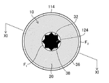
図4に示されるファイバーロッド10は、繊維部分20を備える。繊維部分20は、全体として円柱形状を有し、かつ内部に空間32を画定する断面視で環状の中空構造を有する。空間32は、繊維部分20を有しない領域を意味する。図4に示されるように、空間32は、繊維部分20の2個の底面34に開口を有し、貫通孔を構成する。繊維部分20の対向する表面の距離Aが、1mmから1.6mmの範囲の領域を含んでいる。環状構造の繊維部分20の対向する表面の距離Aは、外面36と内面38との距離となる。図4に示されるファイバーロッド10では、血液検体が外面36から、及び空間32の内面38から繊維部分20に吸収される。また、繊維部分20に吸収された血液検体は、外面36から外部へ、及び内面38から空間32へと放出される。
The
空間32の体積(V1)の繊維部分20の体積(V2)に対する比(V1/V2)は、0.4から1.0の範囲であることが好ましい。空間32と繊維部分20の体積比率を上述の範囲とすることにより、ファイバーロッド10の形状を維持でき、かつ繊維部分20への血液検体の吸収と放出とを容易に行うことができる。
The ratio (V1 / V2) of the volume (V1) of the
繊維部分20が全体として円柱形状で、繊維部分20の内部に画定される空間32も円柱形状であるので、血液検体を等方的に吸収、及び放出ができ、また、ファイバーロッド10の製造が容易になる。但し、繊維部分20の全体形状、及び空間32の形状は、円柱形状に限定されない。また、空間32は、一方の底面34にのみ開口を有する形状であってもよい。
Since the
図5に示されるファイバーロッド10は、繊維部分20を備える。繊維部分20は、全体として円柱形状を有し、かつ繊維部分20の内部に複数の空間40を画定する中空構造を有する。複数の空間40は、それぞれ繊維部分20の2個の底面42に開口を有し、複数の貫通孔を構成する。繊維部分20の対向する表面の距離Aが、1mmから1.65mmの範囲の領域を含んでいる。複数の空間40を画定する中空構造の繊維部分20の対向する表面の距離Aは、外面44と内面46との距離、及び内面46と内面46との距離となる。図5に示されるファイバーロッド10では、血液検体が外面44から、及び複数の空間40の内面46から繊維部分20に吸収される。また、繊維部分20に吸収された血液検体は、外面44から外部へ、及び内面46から空間40へと放出される。繊維部分20に複数の空間40が画定されているので、複数の内面46が形成される。その結果、繊維部分20と外部との接触面積が増えるので、繊維部分20に対する血液検体の吸収、及び放出が容易となる。
The
空間40の体積(V1)の繊維部分20の体積(V2)に対する比(V1/V2)は、0.4から1.0の範囲であることが好ましい。空間40と繊維部分20の体積比率を上述の範囲とすることにより、ファイバーロッド10の形状を維持でき、かつ繊維部分20への血液検体の吸収と放出とを容易に行うことができる。
The ratio (V1 / V2) of the volume (V1) of the
繊維部分20の全体形状、及び空間40の形状は、円柱形状に限定されない。また、空間40は、一方の底面42にのみ開口を有する形状であってもよい。
The overall shape of the
<血液採取器具>
次に、図6から図9を参照して、血液採取器具について説明する。図6の分解図に示されるように、血液採取器具100は、一方に開口112が画定されているケース110と、開口112の側に着脱自在に保持されるファイバーロッド10とを備える。実施形態では、図4に示されるファイバーロッド10を適用した例で説明する。ファイバーロッド10は、空間32を画定する中空構造の繊維部分20を備える。
<Blood sampling device>
Next, the blood sampling device will be described with reference to FIGS. 6 to 9. As shown in the exploded view of FIG. 6, the
ケース110は、開口112の側から他方の側に、ファイバーロッド10を収容する先端収容部114、中央部116、フランジ部118、及び開口122が画定された基端収容部120を備える。ケース110は一体成形物であり、開口112と開口122とは貫通する。
The
図6に示されるように、ファイバーロッド10は先端収容部114に着脱自在に保持される。先端収容部114には、ファイバーロッド10の空間32に挿通される部材124を備える。先端収容部114は略円柱形状であり、先端収容部114の内径とファイバーロッド10の外径とは、略同じ大きさである。部材124はケース110の軸線方向に沿って形成される。軸線方向に沿うとは、軸線方向と平行又は略平行を意味する。
As shown in FIG. 6, the
中央部116は先端収容部114より大きな直径を有し、略円柱形状である。中央部116には、後述するロックレバー300を嵌め込むための開口126が形成されている。採血者は、中央部116と基端収容部120との間のフランジ部118を手指で把持することにより、血液採取器具100を保持できる。
The
基端収容部120は中央部116より大きな直径を有し、略円柱形状である。基端収容部120には、血液採取器具100の軸線方向に沿って、スライド溝128が形成されている。
The base
押し出しロッド200は、開口112と反対の側に位置し、U字型の押し部材210と、操作部214と、押し部材210と操作部214とを連結する連結部材212と、を備える。連結部材212には、ロックレバー300と係合するための開口216が形成されている。操作部214は略円柱形状であり、基端収容部120に操作部214が収容される。
The pushing
操作部214の外周面には、突起218が形成されている。突起218は、基端収容部120のスライド溝128に挿入される。突起218は、スライド溝128に沿って移動できる。スライド溝128に突起218を挿入することにより、押し出しロッド200が軸線方向を中心に回転することを規制する。
A
ロックレバー300は、開口312が形成された矩形の枠体310と、枠体310に直交する方向に4個の脚部314と、を備える。脚部314の先端側には係止爪316がそれぞれ形成されている。脚部314の方向に延びるレバー318が、枠体310に軸支されている。レバー318の先端には連結部材212の開口216に係合するレバー爪部320が設けられている。レバー318の基端にはレバー操作部322が設けられている。レバー操作部322を脚部314の方向に移動させると、レバー318が支軸を中心に回動する。レバー爪部320が枠体310の方向に移動し、開口216とレバー爪部320との係合が解除される。
The
ケース110、押し出しロッド200、及びロックレバー300は、例えば、ポリプロピレンで構成される。
The
図7は、ファイバーロッド10を除き、ケース110と、押し出しロッド200と、ロックレバー300とを組み立てた斜視図である。図7に示されるように、ケース110の基端収容部120に、押し出しロッド200の操作部214が収容される。また、押し出しロッド200の突起218が、基端収容部120のスライド溝128に挿入される。ロックレバー300が、ケース110の開口126(不図示)に取り付けられ、レバー318のレバー爪部320(不図示)が、押し出しロッド200の開口216(不図示)に係合されている。押し出しロッド200の軸線方向の移動が規制される。
FIG. 7 is a perspective view in which the
図8は、図7の透過図である。図8に示されるように、部材124を支持する梁部材130が先端収容部114に設けられる。梁部材130は軸線方向に直交する。梁部材130と先端収容部114とにより画定される隙間は、U字型の押し部材210の通過を許容する。脚部314の係止爪316により連結部材212が係止される。
FIG. 8 is a transparent view of FIG. 7. As shown in FIG. 8, a
図9は、ファイバーロッド10と、ケース110と、押し出しロッド200と、ロックレバー300とを組み立てた斜視図である。図9において、血液採取器具100の理解を容易にするため、符号を省略している。ファイバーロッド10がケース110の開口112の側の先端収容部114に着脱自在に保持される。部材124が、繊維部分20に画定された空間32に挿通される。血液採取器具100を構成するケース110の先端収容部114は透明であることが好ましい。先端収容部114を通して、ファイバーロッド10に吸収される血液検体の量を確認することができる。
FIG. 9 is a perspective view in which the
血液採取器具100は押し出しロッド200を備えるので、血液検体を採取した後、ファイバーロッド10を、ケース110の外に容易に押し出すことができる。
Since the
上述の血液採取器具100による採血方法について説明する。血液検体の採取は、対象者自身が行ってもよく、医師等の有資格者が行ってもよい。好ましい態様では、対象者本人が、ランセットなどのナイフ付の器具を用いて指先などを傷つけて皮膚外にでた血液検体に、血液採取器具100のケース110に保持されるファイバーロッド10を接触させる。ファイバーロッド10の繊維部分20は90%から97%の空隙率を有する。繊維部分20の空隙に血液検体が吸収されるので、血液検体をファイバーロッド10に採取することができる。ファイバーロッド10が全体に赤くなったことを確認した時点で、血液検体の採取を終了する。
The blood collection method using the
次に、図10から図13を参照して、ファイバーロッド10と部材124の他の形態について説明する。図10は、軸線方向に直交する方向の先端収容部114の断面図であり、図11は軸線方向に平行する方向の先端収容部114の断面図である。図10に示されるように、ファイバーロッド10は第4実施形態のファイバーロッドである。先端収容部114に形成された部材124は、断面視で星型八角形の形状を有している。ファイバーロッド10の空間32に部材124が挿通されると、部材124と内面38とが接触しない領域が形成される。その結果、図11に示されるように、部材124とファイバーロッド10とにより、血液検体の流路F1が形成される。流路F1を形成することにより、部材124とファイバーロッド10との間で毛細管現象を作用させることができる。図11の矢印BL1の示す方向から血液検体を繊維部分20の内面38に沿って、吸い上げることができ、内面38からも血液検体を繊維部分20に吸収することができる。また、部材124と内面38とが接触する領域は、ファイバーロッド10を先端収容部114に保持する機能を備える。
Next, other forms of the
図10、及び図11に示されるように、ファイバーロッド10の外径を先端収容部114の内径より小さくすることにより、繊維部分20の外面36と先端収容部114と内面とを離間できる。ファイバーロッド10と先端収容部114とにより血液検体の流路F2が形成される。流路F2を形成することにより、先端収容部114とファイバーロッド10との間で毛細管現象を作用させることができる。図11の矢印BL2の示す方向から血液検体を繊維部分20の外面36に沿って、吸い上げることができ、外面36からも血液検体を繊維部分20に吸収することができる。
As shown in FIGS. 10 and 11, by making the outer diameter of the
図12は、軸線方向に直交する方向の先端収容部114の断面図である。図12に示されるように、ファイバーロッド10は第5実施形態のファイバーロッドであり、繊維部分20には複数の空間40が画定されている。先端収容部114に形成された複数の部材124は、断面視で、それぞれ星型八角形の形状を有している。ファイバーロッド10の空間40に部材124が挿通されると、部材124と内面46とが接触しない領域が形成される。その結果、複数の部材124とファイバーロッド10とにより、血液検体の流路F1が形成される。流路F1を形成することにより、部材124とファイバーロッド10との間で毛細管現象を作用させることができる。血液検体を繊維部分20の内面46に沿って、吸い上げることができ、内面46からも血液検体を繊維部分20に吸収することができる。また、部材124と内面46とが接触する領域は、ファイバーロッド10を先端収容部114に保持する機能を備える。
FIG. 12 is a cross-sectional view of the
図12に示されるように、ファイバーロッド10の外径を先端収容部114の内径より小さくすることより、繊維部分20の外面44と先端収容部114と内面とを離間できる。ファイバーロッド10と先端収容部114とにより血液検体の流路F2が形成される。流路F2を形成することにより、先端収容部114とファイバーロッド10との間で毛細管現象を作用させることができる。血液検体を繊維部分20の外面44に沿って、吸い上げることができ、外面44からも血液検体を繊維部分20に吸収することができる。
As shown in FIG. 12, by making the outer diameter of the
図13は、軸線方向に直交する方向の先端収容部114の断面図である。図12に示されるように、ファイバーロッド10は第5実施形態のファイバーロッドの変形例である。第5実施形態と同様に繊維部分20には複数の空間40が画定されている。一方、第5実施形態と異なり、繊維部分20の外面44は円ではなく、外面44は、4個の半円を連続して繋げた形状を有している。図12と同様に、複数の部材124とファイバーロッド10とにより、血液検体の流路F1が形成される。毛細管現象を利用して、血液検体を繊維部分20の内面48に沿って、吸い上げることができ、内面46からも血液検体を繊維部分20に吸収することができる。
FIG. 13 is a cross-sectional view of the
一方、図13においては、繊維部分20の外面44と先端収容部114とにより液検体の流路F2を形成するため、先端収容部114の内面に複数の部材132を形成している。部材132を形成することにより、外面44と部材132との間で毛細管現象を作用させることができる。したがって、繊維部分20の外面44からも血液検体を吸収することができる。
On the other hand, in FIG. 13, a plurality of
<血液検査キット>
血液検査キットは、上述の血液採取器具100のほか、採取した血液検体を希釈するための希釈液と、血液検体の希釈物を収容するための収容器具と、を含み、血液中に恒常的に存在する標準成分、又は前記希釈液に含有される標準成分であって血液中に存在しない標準成分を用いて血液検体中の対象成分の濃度を分析するための血液検査キットである。
<Blood test kit>
In addition to the above-mentioned
さらに、血液検体の希釈物から血漿を分離回収するための分離器具を備えることが好ましい。 Further, it is preferable to provide a separation device for separating and collecting plasma from the diluted blood sample.
[収容器具]
図14は、血液検体の希釈物を収容するための収容器具の構成の一例を示す断面図である。図14に示されるように、収容器具400は、透明な材質の円筒形状の採血容器410を有する。採血容器410の上端側には、外面に螺子部412が形成され、内面に係止部414が突設されている。また、採血容器410の下端部には、下端側に突出する円錐形状の底部416が形成されている。底部416の周囲に円筒形状の脚部418が形成されている。「上」及び「下」とは、脚部418を載置面に設置した状態における「上」及び「下」を意味する。
[Accommodation equipment]
FIG. 14 is a cross-sectional view showing an example of the configuration of an accommodating device for accommodating a diluted blood sample. As shown in FIG. 14, the
脚部418は、血液の分析検査時に使用するサンプルカップ(不図示)と同一外径を有しており、好ましくは、その下端の対向する位置にそれぞれ鉛直方向にスリット溝420が形成されている。さらに、採血容器410には、図14に示されているように、所要量、例えば、500mm3の希釈液422が収容されることが好ましい。
The
図14に示すように、収容器具400を使用前は、採血容器410の上端開口が、キャップ424によりパッキン426を介して密閉されることが好ましい。
As shown in FIG. 14, before using the
[血液中に恒常的に存在する標準成分]
血漿成分の希釈倍率の高い希釈血漿の希釈後の対象成分について、希釈前の血液の血漿中に存在する濃度を正確に分析するためには、希釈液中にあらかじめ存在する物質の濃度の変化率から求める方法を採用することができる。また、血液中に恒常的に存在する標準成分を用いて血液検体中の対象成分の濃度を分析する方法を採用することも可能である。より少量の血液から血液成分を分析する場合には、血液中に恒常的に存在する標準成分を用いる方法を採用する場合に、測定誤差の小さい測定が可能となるため好ましい。したがって本発明の血液検査キットとしては、血液中に恒常的に存在する標準成分を用いて血液検体中の対象成分の濃度を分析するための、血液検査キットであることが好ましい態様の一つである。
[Standard component that is constantly present in blood]
High dilution ratio of plasma components In order to accurately analyze the concentration of blood before dilution in plasma for the target component after dilution of diluted plasma, the rate of change in the concentration of substances pre-existing in the diluted solution The method obtained from can be adopted. It is also possible to adopt a method of analyzing the concentration of a target component in a blood sample using a standard component that is constantly present in blood. When analyzing a blood component from a smaller amount of blood, it is preferable to adopt a method using a standard component that is constantly present in the blood because measurement with a small measurement error becomes possible. Therefore, one of the preferred embodiments of the blood test kit of the present invention is a blood test kit for analyzing the concentration of a target component in a blood sample using a standard component that is constantly present in blood. There is .
ここで、標準成分を「用いて」とは、標準成分についての標準値(血液中に恒常的に存在する標準成分を用いる場合には、恒常値)に基づき、対象成分の濃度を分析するための希釈倍率を決定する意である。したがって、血液中に恒常的に存在する標準成分を用いて血液検体中の対象成分の濃度を分析する場合には、血液中に恒常的に存在する標準成分の恒常値(標準値)に基づき希釈倍率を決定し、対象成分の濃度を分析することでもある。 Here, "using" the standard component means to analyze the concentration of the target component based on the standard value for the standard component (in the case of using the standard component that is constantly present in blood, the constant value). It is intended to determine the dilution ratio of. Therefore, when analyzing the concentration of the target component in a blood sample using a standard component that is constantly present in blood, it is diluted based on the constant value (standard value) of the standard component that is constantly present in blood. It is also to determine the magnification and analyze the concentration of the target component.
血液中に恒常的に存在する標準成分は、例えば、ナトリウムイオン、塩化物イオン、カリウムイオン、マグネシウムイオン、カルシウムイオン、総タンパク、及びアルブミン等が挙げられる。血液検体の血清及び血漿中に含まれるこれらの標準成分の濃度は、ナトリウムイオン濃度は、134mmol/Lから146mmol/L(平均値:142mmol/L)、塩化物イオン濃度は、97mmol/Lから107mmol/L(平均値:102mmol/L)、カリウムイオン濃度は、3.2mmol/Lから4.8mmol/L(平均値:4.0mmol/L)、マグネシウムイオン濃度は、0.75mmol/Lから1.0mmol/L(平均値:0.9mmol/L)、カルシウムイオン濃度は、4.2mmol/Lから5.1mmol/L(平均値:4.65mmol/L)、総タンパク濃度は、6.7g/100mlから8.3g/100ml(平均値:7.5g/100mL)、アルブミン濃度は、4.1g/100mLから5.1g/100mL(平均値:4.6g/100mL)である。実施形態では、対象者の痛みを和らげるために採血する血液量が非常に少ない場合における対象成分の測定を可能にするためのものであり、微量の血液を希釈液で希釈した際に、希釈液中に存在する「血液中に恒常的に存在する標準成分」の濃度を精度よく測定する必要がある。希釈倍率が高くなると、もともと血液中に存在する成分の希釈液中の濃度が低下し、希釈倍率によっては濃度測定時に、測定誤差を含む可能性がある。したがって、微量な血液成分を希釈倍率高く希釈したときに、上記標準成分を十分に精度高く検出するためには、微量な血液中に高い濃度で存在する標準成分を測定することが好ましい。本発明では、血液検体中に恒常的に存在する成分の中でも高濃度に存在する、ナトリウムイオン(Na+)又は塩化物イオン(Cl−)を用いることが好ましい。さらには、上述の血液中に恒常的に存在する標準成分の中でも血液中に存在する量が一番高いナトリウムイオンを測定することが最も好ましい。ナトリウムイオンは、平均値が標準値(基準範囲の中央値)を表し、その値は、142mmol/Lであり、血漿中の総陽イオンの90モル%以上を占める。 Standard components that are constitutively present in blood include, for example, sodium ion, chloride ion, potassium ion, magnesium ion, calcium ion, total protein, albumin and the like. The concentrations of these standard components contained in the serum and plasma of blood samples are as follows: sodium ion concentration is 134 mmol / L to 146 mmol / L (average value: 142 mmol / L), and chloride ion concentration is 97 mmol / L to 107 mmol. / L (average value: 102 mmol / L), potassium ion concentration is 3.2 mmol / L to 4.8 mmol / L (average value: 4.0 mmol / L), magnesium ion concentration is 0.75 mmol / L to 1 0.0 mmol / L (average value: 0.9 mmol / L), calcium ion concentration from 4.2 mmol / L to 5.1 mmol / L (average value: 4.65 mmol / L), total protein concentration is 6.7 g / 100 ml to 8.3 g / 100 ml (average value: 7.5 g / 100 mL), albumin concentration is 4.1 g / 100 mL to 5.1 g / 100 mL (average value: 4.6 g / 100 mL). In the embodiment, it is intended to enable the measurement of the target component when the amount of blood to be collected is very small in order to relieve the pain of the subject, and when a small amount of blood is diluted with the diluent, the diluent is used. It is necessary to accurately measure the concentration of the "standard component constantly present in blood" present in the blood. When the dilution ratio is increased, the concentration of the component originally present in blood in the diluent decreases, and depending on the dilution ratio, a measurement error may be included in the concentration measurement. Therefore, in order to detect the standard component with sufficiently high accuracy when a trace amount of blood component is diluted with a high dilution ratio, it is preferable to measure the standard component present at a high concentration in the trace amount of blood. In the present invention, it is preferable to use sodium ion (Na + ) or chloride ion (Cl − ), which is present at a high concentration among the components constantly present in the blood sample. Furthermore, it is most preferable to measure the sodium ion having the highest amount present in the blood among the above-mentioned standard components constantly present in the blood. The average value of sodium ions represents a standard value (median value of the reference range), and the value is 142 mmol / L, which accounts for 90 mol% or more of the total cations in plasma.
[血液中に存在しない標準成分]
実施形態の好ましい態様の一つは、血液中に存在しない標準成分を用いて血液検体中の対象成分の濃度を分析するための、血液検査キットである。このような血液検査キットは、血液中に恒常的に存在する標準成分とともに、血液中に存在しない標準成分を用いるためのものであってもよく、血液中に恒常的に存在する標準成分を用いずに、血液中に存在しない標準成分を単独で用いるためのものであってもよい。
[Standard component not present in blood]
One of the preferred embodiments of the embodiment is a blood test kit for analyzing the concentration of a target component in a blood sample using a standard component that is not present in blood. Such a blood test kit may be for using a standard component that is not present in the blood as well as a standard component that is constantly present in the blood, and uses a standard component that is constantly present in the blood. Instead, it may be for using a standard component that is not present in blood alone.
いずれの場合も、血液中に存在しない標準成分は、後述する希釈液に所定の濃度になるように添加して用いることができる。血液中に存在しない標準成分としては、血液検体中に全く含まれないか、若しくは含まれていたとしても極微量である物質を使用することができる。血液中に存在しない標準成分としては、血液検体中の対象成分の測定に干渉を与えない物質、血液検体中の生体酵素の作用を受けて分解しない物質、希釈中で安定な物質、血球膜を透過せず血球中に含まれない物質、緩衝液の保存容器に吸着しない物質、精度良く測定できる検出系が利用できる物質を用いることが好ましい。 In either case, the standard component that is not present in blood can be added to the diluent described later to a predetermined concentration and used. As a standard component that is not present in blood, a substance that is not contained in the blood sample at all, or even if it is contained, can be used in a very small amount. Standard components that do not exist in blood include substances that do not interfere with the measurement of the target component in the blood sample, substances that do not decompose under the action of bioenzymes in the blood sample, substances that are stable during dilution, and blood cell membranes. It is preferable to use a substance that does not permeate and is not contained in blood cells, a substance that does not adsorb to the storage container of the buffer solution, and a substance that can use a detection system that can measure accurately.
血液中に存在しない標準成分としては、希釈液に添加した状態で長期間保管しても安定した物質が好ましい。血液中に存在しない標準成分の例としては、グリセロール三リン酸、アルカリ金属としてLi、Rb、Cs、又はFr、そしてアルカリ土類金属としてはSr、Ba、又はRaが挙げられ、Li及びグリセロール三リン酸が好ましい。 As a standard component that does not exist in blood, a substance that is stable even when stored in a diluted solution for a long period of time is preferable. Examples of standard components that are not present in blood include glycerol triphosphate, Li, Rb, Cs, or Fr as alkali metals, and Sr, Ba, or Ra as alkaline earth metals, and Li and glycerol tri. Phosylate is preferred.
これらの血液中に存在しない標準成分は、血液希釈後の濃度測定時に第二の試薬を添加することで発色させ、その発色濃度から希釈血液中の濃度を求めることができる。例えば、希釈液に添加したリチウムイオンの測定は、キレート比色法(ハロゲン化ポルフィリンキレート法:パーフルオロ−5,10,15,20−テトラフェニル−21H,23H−ポルフィリン)を利用して生化学自動分析装置で大量試料を微量の試料で容易に測定できる。また、グリセロール三リン酸の測定は、例えば、公知資料である、「在宅医療革命」(臨床検査 Vol.59、p397、2015年)に記載された、酸化縮合による色素発色の濃度測定を利用して生化学自動分析装置で大量試料を微量の試料で容易に測定できる。 These standard components that are not present in blood can be colored by adding a second reagent at the time of concentration measurement after blood dilution, and the concentration in diluted blood can be determined from the color development concentration. For example, the measurement of lithium ions added to the diluent is biochemical using the chelate chromogenic method (porphyrin halogenated chelate method: perfluoro-5,10,15,20-tetraphenyl-21H, 23H-porphyrin). A large amount of sample can be easily measured with a small amount of sample by an automatic analyzer. In addition, the measurement of glycerol triphosphate uses, for example, the measurement of the concentration of dye color development by oxidative condensation described in "Home Medical Revolution" (clinical examination Vol.59, p397, 2015), which is a well-known material. A large amount of sample can be easily measured with a small amount of sample with an automatic biochemical analyzer.
[希釈液]
血液検査キットは、採取した血液検体を希釈するための希釈液を含む。希釈液は、血液検査キットが血液中に恒常的に存在する標準成分を用いて、血液検体中の対象成分の濃度を分析するためのものである場合、血液中に恒常的に存在する標準成分を含有しない。「含有しない」とは、「実質的に含有しない」ことを意味する。ここで、「実質的に含有しない」とは、希釈倍率を求める時に使用する恒常性のある物質をまったく含まないか、あるいは含まれていたとしても、血液検体を希釈した後の希釈液の恒常性のある物質の測定に影響を及ぼさない程度の極微量の濃度で含まれる場合を意味する。血液中に恒常的に存在する標準成分として、ナトリウムイオン又は塩化物イオンを用いる場合には、希釈液としては、ナトリウムイオン又は塩化物イオンを実質的に含有しない希釈液を使用する。
[Diluted solution]
The blood test kit contains a diluent for diluting the collected blood sample. The diluent is the standard component that is constitutively present in the blood when the blood test kit is for analyzing the concentration of the target component in the blood sample using the standard component that is constitutively present in the blood. Does not contain. "Not contained" means "substantially not contained". Here, "substantially free" means that the substance having homeostasis used when determining the dilution ratio is not contained at all, or even if it is contained, the dilution solution after diluting the blood sample is constitutive. It means that it is contained in a very small concentration that does not affect the measurement of a substance having sex. When sodium ion or chloride ion is used as a standard component constantly present in blood, a diluted solution containing substantially no sodium ion or chloride ion is used as the diluent.
血液のpHは、健常者では通常pH7.30からpH7.40程度で一定に保たれていることから、対象成分の分解や変性を防止するために、希釈液は、pH6.5からpH8.0の範囲、好ましくはpH7.0からpH7.5の範囲、さらに好ましくはpH7.3からpH7.4の範囲のpH域で緩衝作用を有する緩衝液であることが好ましく、希釈液は、pHの変動を抑える緩衝成分を含有する緩衝液であることが好ましい。 Since the pH of blood is usually kept constant at about pH 7.30 to pH 7.40 in healthy subjects, the diluted solution is pH 6.5 to pH 8.0 in order to prevent decomposition and denaturation of the target component. It is preferable that the buffer solution has a buffering action in the range of pH 7.0 to pH 7.5, more preferably in the pH range of pH 7.3 to pH 7.4, and the diluent is a fluctuation in pH. It is preferable that the buffer solution contains a buffer component that suppresses the pH.
従来、緩衝液の種類としては、酢酸緩衝液(Na)、リン酸緩衝液(Na)、クエン酸緩衝液(Na)、ホウ酸緩衝液(Na)、酒石酸緩衝液(Na)、Tris(トリス(ヒドロキシメチル)アミノエタン)緩衝液(Cl)、Hepes([2−[4−(2−ヒドロキシエチル)−1−ピペラジニル]エタンスルホン酸])緩衝液、リン酸緩衝生理食塩水(Na)等が知られている。これらの中でpH7.0からpH8.0付近の緩衝液としては、リン酸緩衝液、Tris緩衝液、Hepes緩衝液が代表的なものである。しかしながら、リン酸緩衝液はリン酸のナトリウム塩が含まれていること、Tris緩衝液は、解離pKaは8.08であるため、pH7.0からpH8.0付近で緩衝能を持たせるためには通常は塩酸と組み合わせて使用されること、Hepesのスルホン酸の解離のpKaは7.55であるが、イオン強度一定での緩衝溶液を調整するため、通常は水酸化ナトリウムと塩化ナトリウムとHEPESの混合物が用いられることから、これらはpHを一定に保つ作用を有する緩衝液としては有用であるが、実施形態において外部標準物質として用いることが好ましい物質であるナトリウムイオンあるいは塩化物イオンを含有するため、血液検査キットが血液中に恒常的に存在する標準成分を用いて血液検体中の対象成分の濃度を分析するためのものである場合、適用は好ましくない。 Conventionally, the types of buffers have been acetate buffer (Na), phosphate buffer (Na), citrate buffer (Na), borate buffer (Na), tartrate buffer (Na), and Tris. (Hydroxymethyl) aminoethane) buffer (Cl), Hepes ([2- [4- (2-hydroxyethyl) -1-piperazinyl] ethanesulfonic acid]) buffer, phosphate buffer physiological saline (Na), etc. Are known. Among these, typical buffer solutions having a pH of 7.0 to 8.0 are phosphate buffer solutions, Tris buffer solutions, and Hepes buffer solutions. However, the phosphate buffer contains a sodium salt of phosphate, and the Tris buffer has a dissociation pKa of 8.08, so that it has a buffering capacity in the vicinity of pH 7.0 to pH 8.0. Is usually used in combination with hydrochloric acid, the pKa of Hepes sulfonic acid dissociation is 7.55, but usually sodium hydroxide, sodium chloride and HEEPS to prepare a buffer solution with constant ionic strength. These are useful as buffers having the effect of keeping the pH constant because a mixture of the above is used, but they contain sodium ion or chloride ion, which are preferable substances to be used as an external standard substance in the embodiment. Therefore, application is not preferable when the blood test kit is for analyzing the concentration of the target component in a blood sample using a standard component that is constantly present in the blood.
血液検査キットが血液中に恒常的に存在する標準成分を用いて血液検体中の対象成分の濃度を分析するためのものである場合、用いる緩衝液としては、ナトリウムイオン又は塩化物イオンを含有しない(「含有しない」の意味は、すでに述べたとおりである。)ことが好ましい。このような緩衝液は好ましくは、2−アミノ−2−メチル−1−プロパノール(AMP)、2−エチルアミノエタノール、N−メチル−D−グルカミン、ジエタノールアミン、及びトリエタノールアミンからなる群から選択される少なくとも1種のアミノアルコール化合物、並びにGood’s緩衝液(グッドバッファー)でpKaが7.4付近の緩衝剤であるHEPESとも称する2−[4−(2−ヒドロキシエチル)1−ピペラジニル]エタンスルホン酸(pKa=7.55)、TESとも称するN−トリス(ヒドロキシメチル)メチル−2−アミノエタンスルホン酸(pKa=7.50)、MOPSとも称する3−モルホリノプロパンスルホン酸(pKa=7.20)、及びBESとも称するN,N−ビス(2−ヒドロキシエチル)−2−アミノエタンスルホン酸(pKa=7.15)からなる群から選択される緩衝剤を含む希釈液である。上記の中でも、2−アミノー2−メチル−1−プロパノール(AMP)とHEPES、TES、MOPS又はBESとの組み合わせが好ましく、さらに、2−アミノー2−メチル−1−プロパノール(AMP)とHEPESとの組み合わせが最も好ましい。なおpKaは、酸解離定数を表す。 When the blood test kit is for analyzing the concentration of the target component in the blood sample using the standard component constantly present in the blood, the buffer solution used does not contain sodium ion or chloride ion. (The meaning of "not contained" is as described above.) It is preferable. Such a buffer is preferably selected from the group consisting of 2-amino-2-methyl-1-propanol (AMP), 2-ethylaminoethanol, N-methyl-D-glucamine, diethanolamine, and triethanolamine. 2- [4- (2-Hydroxyethyl) 1-piperazinyl] ethane, also referred to as HEPES, which is a buffer with a pKa of around 7.4 in Good's buffer, as well as at least one aminoalcohol compound. Sulfonic acid ( pKa = 7.55), N-tris (hydroxymethyl) methyl-2-aminoethanesulfonic acid (pKa = 7.50), also known as TES, 3-morpholinopropanesulfonic acid (pKa = 7.50), also known as MOPS. 20), and a diluent comprising N that also referred to as BES, an N- bis (2-hydroxyethyl) buffering agents selected from the group consisting of 2-amino-ethanesulfonic acid (pKa = 7.15). Among the above, a combination of 2-amino-2-methyl-1-propanol (AMP) and HEPES, TES, MOPS or BES is preferable, and further, 2-amino-2-methyl-1-propanol (AMP) and HEPES are used. The combination is most preferred. Note that pKa represents the acid dissociation constant.
上記緩衝液を調製するためには、アミノアルコールとGood‘s緩衝液を1:2から2:1、好ましくは1:1.5から1.5:1、さらに好ましくは1:1の濃度比で混合すればよい。緩衝液の濃度は限定されないが、アミノアルコール又はGood‘s緩衝液の濃度は、0.1mmol/Lから1000mmol/L、好ましくは、1mmol/Lから500mmol/L、さらに好ましくは10mmol/Lから100mmol/Lである。 In order to prepare the above buffer, the concentration ratio of aminoalcohol and Good's buffer is 1: 2 to 2: 1, preferably 1: 1.5 to 1.5: 1, and more preferably 1: 1. It may be mixed with. The concentration of the buffer is not limited, but the concentration of aminoalcohol or Good's buffer is 0.1 mmol / L to 1000 mmol / L, preferably 1 mmol / L to 500 mmol / L, more preferably 10 mmol / L to 100 mmol. / L.
緩衝液中には、分析対象成分を安定に保つことを目的にキレート剤、界面活性剤、抗菌剤、防腐剤、補酵素、糖類等が含有されていてもよい。キレート剤としては、エチレンジアミン四酢酸(EDTA)塩、クエン酸塩、シュウ酸塩等が挙げられる。界面活性剤としては、例えば、陽イオン界面活性剤、陰イオン界面活性剤、両性界面活性剤又は非イオン界面活性剤が挙げられる。防腐剤としては、例えば、アジ化ナトリウムや抗生物質等が挙げられる。補酵素としては、ピリドキサールリン酸、マグネシウム、亜鉛等が挙げられる。赤血球安定化剤の糖類としては、マンニトール、デキストロース、オリゴ糖等が挙げられる。特に、抗生物質の添加により、手指採血時に手指表面から一部混入する細菌の増殖を抑えることができ、細菌による生体成分の分解を抑制し、生体成分の安定化を図ることができる。 The buffer solution may contain a chelating agent, a surfactant, an antibacterial agent, a preservative, a coenzyme, a saccharide, or the like for the purpose of keeping the component to be analyzed stable. Examples of the chelating agent include ethylenediaminetetraacetic acid (EDTA) salt, citrate, oxalate and the like. Examples of the surfactant include a cationic surfactant, an anionic surfactant, an amphoteric surfactant or a nonionic surfactant. Examples of the preservative include sodium azide, antibiotics and the like. Examples of the coenzyme include pyridoxal phosphate, magnesium, zinc and the like. Examples of the saccharide of the erythrocyte stabilizer include mannitol, dextrose, oligosaccharide and the like. In particular, by adding an antibiotic, it is possible to suppress the growth of bacteria that are partially mixed from the surface of the fingers when collecting blood from the fingers, suppress the decomposition of the biological components by the bacteria, and stabilize the biological components.
緩衝液はまた、血液中に存在しない標準成分を用いて対象成分を分析するための血液検査キットにおいては、この血液中に存在しない標準成分を含む。後述する内部標準物質を含まず、血液分析の測定系に干渉を与えないことも重要である。 The buffer also contains a standard component that is not present in the blood in a blood test kit for analyzing the target component using a standard component that is not present in the blood. It is also important that it does not contain the internal standard substances described later and does not interfere with the measurement system of blood analysis.
全血を希釈するとの観点からは、緩衝液の浸透圧を血液と同等(285mOsm/kg(mOsm/kgは、溶液の水1kgが持つ浸透圧で、イオンのミリモル数をあらわす))又はそれ以上とすることにより血球の溶血を防止することができる。浸透圧は、対象成分の測定、及び血液中に恒常的に存在する標準成分の測定に影響しない塩類、糖類又は緩衝剤等により、等張に調整することができる。緩衝液の浸透圧は、浸透圧計により測定することができる。 From the viewpoint of diluting whole blood, the osmotic pressure of the buffer solution is equal to or higher than that of blood (285 mOsm / kg (mOsm / kg is the osmotic pressure of 1 kg of water in solution and represents the number of millimolars of ions)) or higher. By doing so, hemolysis of blood cells can be prevented. The osmotic pressure can be adjusted isotonic with salts, sugars, buffers, etc. that do not affect the measurement of the target component and the measurement of the standard component that is constantly present in blood. The osmotic pressure of the buffer solution can be measured by an osmometer.
血液検査として、肝機能、腎機能、メタボリズムなど、特定の臓器、特定の疾患を検査する場合には、臓器や疾患に特有の複数の測定対象成分の情報を入手して、臓器の状態、生活習慣の予測などを行うために、一般的には、複数の測定対象成分の分析が同時に行われる。例えば、肝臓の状態を検査するためには、一般的には、ALT(アラニントランスアミナーゼ)、AST(アスパラギン酸アミノトランスフェラーゼ)、γ―GTP(γグルタミルトランスペプチダーゼ)、ALP(アルカリホスファターゼ)、総ビリルビン、総タンパク、アルブミン等、数種類以上もの物質の血液中の濃度が測定される。このように、複数の対象成分を一つの血液検体から測定するためには、再測定の可能性も考慮して、希釈された血液の量はある程度必要となる。したがって、採取した血液を希釈する希釈液は、ある程度の量を確保することが重要である。しかしながら、被検者の侵襲性を少しでも低く抑えることを考慮すると、採血量は微量となるため、希釈倍率は例えば、7倍程度以上の高倍率となる。 When examining a specific organ or a specific disease such as liver function, renal function, or metabolism as a blood test, obtain information on multiple measurement target components specific to the organ or disease, and obtain information on the condition and life of the organ. In general, a plurality of components to be measured are analyzed at the same time in order to predict habits and the like. For example, in order to examine the condition of the liver, generally, ALT (alanine transaminase), AST (aspartate aminotransferase), γ-GTP (γ-glutamyl transpeptidase), ALP (alkaline phosphatase), total bilirubin, The concentration of several or more substances in the blood, such as total protein and albumin, is measured. As described above, in order to measure a plurality of target components from one blood sample, a certain amount of diluted blood is required in consideration of the possibility of remeasurement. Therefore, it is important to secure a certain amount of diluent for diluting the collected blood. However, considering that the invasiveness of the subject is suppressed as low as possible, the amount of blood collected is very small, so that the dilution ratio is, for example, a high ratio of about 7 times or more.
(血液検体の希釈物)
収容器具400の採血容器410からキャップ424を取り外す。採血容器410の上端開口から、血液採取器具100により血液検体を吸収したファイバーロッド10を、希釈液422に投入する。ファイバーロッド10上端開口をキャップ424により密封する。
(Diluted blood sample)
Remove the
図15に示されるように、採血容器410の上部を持ち、採血容器410を振り子状に数十回振り、ファイバーロッド10から血液検体を希釈液422に放出する。血液検体を希釈液422に溶け込ませることにより、血液検体の希釈物が収容器具400に収容される。
As shown in FIG. 15, the upper part of the
実施形態のファイバーロッド10は、異なる繊維径を持つ第1繊維と第2繊維とにより構成され、90%から97%の範囲の空隙率を持つ繊維部分20を有し、繊維部分の対向する表面の距離が、1mmから1.6mmの範囲内である領域を含むので、血液検体を容易に希釈液422に放出することができる。また、繊維部分20に空間32が画定される場合、繊維部分20の外面36及び内面38が希釈液422に接触するので、より多くの血液検体を放出することができる。
The
希釈液422が全体として赤くなれば、採血容器410を振ることを終える。
When the diluent 422 turns red as a whole, the shaking of the
[分離器具]
血液採取器具100により採取された血液検体は、分析が行われるまで、希釈された状態で、収容器具400の中で長時間経過する可能性がある。その間に、例えば赤血球の溶血が起こると、血球内に存在する物質や酵素などが血漿あるいは血清中に溶出して検査結果に影響を与えたり、溶出したヘモグロビンが有する吸収により、分析対象成分の光学的な吸収などの光情報で分析対象成分量を測定する場合に影響を及ぼす可能性がある。したがって、溶血を防止することが好ましい。そのため、血液検体の希釈物から血漿を分離回収するための分離器具を血液検査キットに含む態様が好ましい。分離器具の好ましい例は、分離膜である。分離膜は、例えば血液検体の希釈物に圧力を加えることによって、血球成分は分離膜で捕獲し、血漿成分を通過させて、血球を分離して血漿成分を回収するように用いることができる。この場合、抗凝固剤を用いることが好ましい。また、測定の精度を確保するために、分離膜を通過した血漿が血球側へ逆流しないことが好ましく、そのためには具体的には、特開2003−270239号公報に記載の、逆流防止手段をキットの構成要素とすることができる。
[Separation device]
The blood sample collected by the
図16は、分離器具を保持する保持器具の一例を示す図である。図16に示されるように、保持器具500は、収容器具400の採血容器410に嵌挿可能な筒体510と、筒体510に取り付けられたキャップピストン512と、キャップピストン512の下端に設けられた封止器具として機能する密閉蓋514とを備える。
FIG. 16 is a diagram showing an example of a holding device for holding the separating device. As shown in FIG. 16, the holding
筒体510は透明な材質製で円筒形状を有している。筒体510の上端部542には拡径部516が形成されている。拡径部516は薄肉部518を介して本体部520と接続されている。筒体510の下端部には、縮径部522が形成されている。縮径部522の内面には係止突起部524が形成されている。さらに、縮径部522の下端部には外鍔部526が形成されている。外鍔部526の下端開口部は分離器具として機能する濾過膜528により覆われている。濾過膜528は血液中の血漿の通過を許容し、血球の通過を阻止するよう構成される。縮径部522の外周にはシリコンゴム製のカバー530が装着されている。
The
キャップピストン512は、略円筒形状の摘み部532と、摘み部532と同心で下方に延びる心棒部534とで構成されている。摘み部532の内側上端部には筒体510の拡径部516が嵌合可能な円筒状の空間536が形成され、その下方は螺刻され、螺子に螺合可能となっている。心棒部534はその下端部538がピン状に形成され、下端部538に密閉蓋514が着脱可能に設けられている。密閉蓋514はシリコンゴム製である。密閉蓋514の下端部が外鍔状に形成された略円柱状を成し、外周にわたり段差部540が形成されている。摘み部532は頂部544を有し、頂部544の内面と拡径部516とは接触する。
The
次に、図17に示されるように、ファイバーロッド10と血液検体の希釈物が収容された採血容器410から、キャップ424、及びパッキン426を採血容器410から取外す。この状態において、キャップピストン512が取り付けられた筒体510を採血容器410内に嵌挿する。
Next, as shown in FIG. 17, the
次に、図18に示されるように、摘み部532を螺子部412に螺合させる。最初、摘み部532と筒体510とが回転する。採血容器410の係止部414が、筒体510の外周面に形成されたストッパ部(不図示)に係止すると、筒体510の回転が拘束され、薄肉部518はねじりにより破断する。この結果、筒体510は本体部520と拡径部516とに分離される。さらに摘み部532を回転させると、本体部520の上端部542が拡径部516の内側の空間536に入り込む。摘み部532の頂部544の内面により筒体510は下方に押圧されるようになるので、筒体510はさらに降下する。
Next, as shown in FIG. 18, the
筒体510の降下に伴い、筒体510に保持される濾過膜528は、採血容器410の底部416の側に移動する。その際、濾過膜528を通って血漿が筒体510の側に移動し、血球は濾過膜528を通過できずに採血容器410の側に残る。
As the
カバー530の外径は筒体510の本体部520の外径より大きいので、筒体510は採血容器410の内面に密着した状態で降下する。したがって、筒体510を採血容器410に嵌挿させる過程で、採血容器410の中の希釈液422が採血容器410と筒体510との隙間を通って外部に漏出するおそれはない。
Since the outer diameter of the
摘み部532を最下部まで螺子部412に螺合させると、密閉蓋514は縮径部522に嵌合する。採血容器410と筒体510との間の流路は密閉蓋514により密閉される。密閉蓋514は、逆流に起因する血漿と血球の混合を防止する。
When the
採血容器410は、希釈液が収容された収容器具を構成し、また血液検体の希釈物を収容するための収容器具をも構成する。また、採血容器410に嵌挿され、血漿と血球とを分離した状態において、筒体510は、回収した血漿を収容するための収容器具を構成する。血液検体を収容するための収容器具は、採血容器410と筒体510の組み合わせに対応する。すなわち、希釈された血液検体を収容するための収容器具は1個でも2個以上の組み合わせでもよい。
The
血液検査キットは、100μL以下の採血量であっても、測定精度よく分析対象成分を分析できる方法を実現可能とするものである。対象者に、100μL以下の少ない採血量でも精度よく測定することが可能であることや、血液採取器具100のファイバーロッド10によりどの程度まで血液検体を採取すべきか等の情報が記載された取り扱い説明書を含む血液検査キットであることが好ましい。
The blood test kit makes it possible to realize a method capable of analyzing a component to be analyzed with high measurement accuracy even if the amount of blood collected is 100 μL or less. Instructions for handling that describe to the subject information such as that it is possible to accurately measure even a small blood collection volume of 100 μL or less, and to what extent a blood sample should be collected by the
<血液分析方法>
実施形態の血液検査キットを用いた血液分析方法について説明する。血液分析方法は、ヒトに対する医療行為(医師が行う行為)である態様とヒトに対する医療行為ではない態様(例えば、採血者が患者自身であり、かつ分析者が医師以外の者である態様、非ヒト動物に対する態様、等)が含まれる。実施形態の血液分析方法は、対象者自身が血液を採取する自己採血で実施してもよいし、医師等の有資格者が注射器を使用して血液を採取する一般採血においても実施してもよい。好ましい態様としては、患者本人が、ランセットなどのナイフ付の器具を用いて指先などを傷つけて皮膚外にでた血液を採取する。
<Blood analysis method>
A blood analysis method using the blood test kit of the embodiment will be described. The blood analysis method includes a mode in which the blood sample is a medical practice for humans (an act performed by a doctor) and a mode in which the blood sample is not a medical practice for humans (for example, the blood collector is the patient himself and the analyst is a person other than the doctor). Aspects for human animals, etc.) are included. The blood analysis method of the embodiment may be carried out by self-collecting blood by the subject himself or by collecting blood by a qualified person such as a doctor using a syringe. good. In a preferred embodiment, the patient himself / herself uses a knife-equipped device such as a lancet to injure a fingertip or the like to collect blood that has come out of the skin.
本分析対象となる生体試料は血液であり、血液とは、血清又は血漿を含む概念である。好ましくは、被検者より微量の血液を採取し、緩衝液で希釈した後、フィルタや遠心分離により血球を分離することにより得られた血漿又は血清を用いることができる。血液検体の成分としては、分離手段により血液検体から分離された血漿成分であることが好ましい。血液検体の起源はヒトに限定されず、ヒト以外の動物(非ヒト動物)である哺乳類、鳥類、魚類等であっても良い。ヒト以外の動物としては、例えば、ウマ、ウシ、ブタ、ヒツジ、ヤギ、イヌ、ネコ、マウス、クマ、パンダ等が挙げられる。好ましくは、生体試料の起源はヒトである。 The biological sample to be analyzed is blood, and blood is a concept including serum or plasma. Preferably, plasma or serum obtained by collecting a small amount of blood from a subject, diluting it with a buffer solution, and then separating blood cells by a filter or centrifugation can be used. The component of the blood sample is preferably a plasma component separated from the blood sample by a separation means. The origin of the blood sample is not limited to humans, and may be mammals, birds, fish, etc., which are animals other than humans (non-human animals). Examples of non-human animals include horses, cows, pigs, sheep, goats, dogs, cats, mice, bears, pandas and the like. Preferably, the origin of the biological sample is human.
血液分析方法の第一の態様としては、血液検体中に恒常的に存在する標準成分を用いて、対象成分の濃度の分析を行う。血液検体中に恒常的に存在する標準成分については、[1]での説明が、ここでもそのまま当てはまる。 As the first aspect of the blood analysis method, the concentration of the target component is analyzed using a standard component that is constantly present in the blood sample. Regarding the standard component that is constantly present in the blood sample, the explanation in [1] still applies here.
被検者の血液中における血漿成分の占有率は、容積の比率で約55%であるが、被検者の塩分摂取量の変化などで変動する。そのため、実施形態においては、血漿中に恒常的に存在する標準成分の標準値を用いて血漿の希釈倍率を算出し、算出した希釈倍率を用いて血液検体中の血漿中の対象成分の濃度を分析する。希釈倍率を算出する方法としては、血漿の希釈液中の外部標準物質(例えば、ナトリウムイオンなど)の測定値(濃度X)と、血液検体の血漿中に含まれる上記外部標準物質(例えば、ナトリウムイオンなど)の既知濃度値(濃度Y;ナトリウムイオンの場合には142mmol/L)とから、血液検体中の血漿成分の希釈倍率(Y/X)を算出することにより希釈倍率を求めることができる。この希釈倍率を用いて、血漿の希釈液中の対象成分の測定値(濃度Z)を測定し、この測定値に希釈倍率を掛け合わせることにより、実際に血液検体の血漿中に含まれる分析対象成分の濃度[Z×(Y/X)]を測定することが可能となる。 The occupancy rate of plasma components in the blood of a subject is about 55% by volume, but it varies depending on changes in the salt intake of the subject. Therefore, in the embodiment, the dilution ratio of plasma is calculated using the standard value of the standard component constantly present in plasma, and the concentration of the target component in plasma in the blood sample is calculated using the calculated dilution ratio. analyse. As a method for calculating the dilution ratio, a measured value (concentration X) of an external standard substance (for example, sodium ion) in the diluted solution of plasma and the above external standard substance (for example, sodium) contained in the plasma of a blood sample are used. The dilution ratio can be obtained by calculating the dilution ratio (Y / X) of the plasma component in the blood sample from the known concentration value (concentration Y; 142 mmol / L in the case of sodium ion) of (ion, etc.). .. Using this dilution ratio, the measured value (concentration Z) of the target component in the diluted solution of plasma is measured, and by multiplying this measured value by the dilution ratio, the analysis target actually contained in the plasma of the blood sample. It becomes possible to measure the concentration [Z × (Y / X)] of the component.
ナトリウムイオンなどの濃度は、例えば、炎光光度法、ガラス電極法、滴定法、イオン選択電極法、酵素活性法等により測定することができる。特に好ましい態様において、ナトリウムイオンの測定はβ−ガラクトシダーゼがナトリウムイオンで活性化することを利用し、緩衝液で希釈された試料のナトリウムイオン濃度とガラクトシダーゼ活性が比例関係にあることを利用した酵素的測定法が採用される。 The concentration of sodium ions and the like can be measured by, for example, a flame photometric method, a glass electrode method, a titration method, an ion selection electrode method, an enzyme activity method, or the like. In a particularly preferred embodiment, the measurement of sodium ions utilizes the activation of β-galactosidase with sodium ions, and is enzymatically utilizing the proportional relationship between the sodium ion concentration of the sample diluted with the buffer and the galactosidase activity. The measurement method is adopted.
また、部材に由来する標準成分の量を規定した血液検査キットが実際に使用されているか、また、血液の希釈と血漿の回収の方法が正常に行われているか確証するためには、血漿中の別の標準成分から独立に希釈倍率を追加的に求めて、その値が上で求めた希釈倍率と一致することを確認することが好ましい。一致するとは、2つの測定値(a,b)において、それらの差のそれらの平均値に対する割合、すなわち|a−b|/{(a+b)/2}×100が、20%以下であることであり、好ましくは10%以下であることであり、より好ましくは5%以下であることである。これにより、血液検体中の対象成分の濃度の分析が正常に行われていることの検証が可能となる。ここで、ナトリウムイオン又は塩化物イオン以外の血漿中に恒常的に存在する標準成分の例としては、総タンパク又はアルブミンから選択されることが好ましく、総タンパクであることがより好ましい。総タンパクの測定法は、ビューレット法や、紫外吸収法、ブレッドフォード法、ローリー法、ビシンコニン酸(Bicinchoninic Acid:BCA)法、蛍光法など公知の方法があり、測定試料の特性や感度、試料量などに応じて適宜使用する方法を選択することができる。 In addition, in order to confirm whether a blood test kit that specifies the amount of standard components derived from the members is actually used, and whether the methods of diluting blood and collecting plasma are performed normally, in plasma. It is preferable to additionally determine the dilution factor independently of the other standard component of and confirm that the value is consistent with the dilution factor determined above. Matching means that in the two measurements (a, b), the ratio of their differences to their average, ie | a-b | / {(a + b) / 2} x 100, is 20% or less. It is preferably 10% or less, and more preferably 5% or less. This makes it possible to verify that the concentration of the target component in the blood sample has been analyzed normally. Here, as an example of a standard component constitutively present in plasma other than sodium ion or chloride ion, it is preferable to select from total protein or albumin, and more preferably total protein. There are known methods for measuring total protein, such as the Buret method, ultraviolet absorption method, Breadford method, Lowry method, Bicinchoninic Acid (BCA) method, and fluorescence method. The method to be used can be appropriately selected according to the amount and the like.
血液分析方法の第二の態様としては、血液中に存在しない標準成分を用いて、対象成分の濃度の分析を行う。この場合、血液中に存在しない標準成分を含む希釈液を含む血液検査キットを用いる。 As a second aspect of the blood analysis method, the concentration of the target component is analyzed using a standard component that does not exist in the blood. In this case, a blood test kit containing a diluent containing a standard component that is not present in the blood is used.
血液分析方法の第三の態様としては、血液中に恒常的に存在する標準成分、及び血液中に存在しない標準成分を用いて、対象成分の濃度の分析を行う。2つの標準成分を併用することで、より信頼性の高い分析方法とすることができる。 As a third aspect of the blood analysis method, the concentration of the target component is analyzed using a standard component that is constantly present in the blood and a standard component that is not present in the blood. By using the two standard components together, a more reliable analysis method can be obtained.
このとき、血液検体の希釈倍率は、血液中に恒常的に存在する標準成分としてナトリウムイオンを、血液中に存在しない標準成分としてリチウムイオンを用い、ナトリウムイオンの測定をβ−ガラクトシダーゼ活性が比例関係にあることを利用した酵素活性法(後述)で行い、リチウムイオンの測定をキレート比色法(後述)で行う場合には、下記式1から4のいずれかの式で算出することができる。
At this time, the dilution ratio of the blood sample uses sodium ion as a standard component constantly present in blood and lithium ion as a standard component not present in blood, and β-galactosidase activity is proportionally related to the measurement of sodium ion. When the lithium ion is measured by the chelate colorimetric method (described later) by the enzyme activation method (described later) utilizing the above, it can be calculated by any of the following

上記式において、A、B、C、D、B’及びXは、以下のように定義される。
A : 緩衝液を発色させた際の吸光度
B : 血漿添加後の吸光度変化量
C : 血漿ナトリウム中央値142 mmol/Lの吸光度
D : 血漿希釈後のナトリウムイオン濃度における吸光度
B’: 血漿ナトリウムの吸光度から算出した希釈倍率による、希釈血漿中の血液中に存在しない標準成分の吸光度の補正値
X : 血漿希釈倍数
希釈率を求める際のもう一つの算出方法として、二乗平均法を用いた式5で算出し、希釈液中の分析対象成分の濃度に、式5で算出した希釈率を乗じて血液検体の成分中の対象成分の濃度を分析する態様も好ましい。
In the above equation, A, B, C, D, B'and X are defined as follows.
A: Absorptivity when the buffer solution is colored B: Amount of change in absorbance after addition of plasma C: Absorptivity of median plasma sodium 142 mmol / L D: Absorbency at sodium ion concentration after plasma dilution B': Absorption of plasma sodium Correction value of the absorbance of standard components not present in blood in diluted plasma based on the dilution ratio calculated from X: Plasma dilution multiple As another calculation method for determining the dilution ratio,
![]()
![]()
血液検体の成分中の対象成分の濃度は、希釈液中の対象成分の濃度から、上記希釈倍率に基づいて算出できる。 The concentration of the target component in the components of the blood sample can be calculated from the concentration of the target component in the diluent based on the above dilution ratio.
分析の対象成分は限定されず、生体試料中に含まれるあらゆる物質が対象となる。例えば臨床診断に用いられる血液中の生化学検査項目、腫瘍マーカーや肝炎のマーカー等各種疾患のマーカー等が挙げられ、タンパク質、糖、脂質、低分子化合物等が挙げられる。また、測定は物質濃度だけでなく、酵素等の活性を有する物質の活性も対象となる。各対象成分の測定は、公知の方法で行うことができる。 The target components for analysis are not limited, and all substances contained in the biological sample are targeted. For example, biochemical test items in blood used for clinical diagnosis, markers for various diseases such as tumor markers and hepatitis markers, and the like, and proteins, sugars, lipids, low molecular weight compounds, and the like can be mentioned. In addition, the measurement covers not only the substance concentration but also the activity of a substance having an activity such as an enzyme. The measurement of each target component can be carried out by a known method.
ナトリウムイオンの測定ではナトリウムイオンにより酵素ガラクトシダーゼは酵素活性が活性化することから、緩衝液で希釈された非常に低濃度ナトリウムイオン(24 mmol/L以下)試料を数μLで測定する酵素的測定法が使用できる。この方法は生化学・免疫自動分析装置に適応でき、ナトリウムイオン測定のために別の測定機器を必要としない点で効率性が高く経済的である。 In the measurement of sodium ions, the enzyme activity of galactosidase is activated by sodium ions. Therefore, an enzymatic measurement method for measuring a very low-concentration sodium ion (24 mmol / L or less) sample diluted with a buffer solution in a few μL. Can be used. This method is suitable for biochemical / immunoautomatic analyzers and is highly efficient and economical in that it does not require a separate measuring instrument for sodium ion measurement.
以下、本発明の実施例を挙げ、本発明を、より詳細に説明する。但し、本発明は、これらの実施例に何ら限定されるものではない。 Hereinafter, the present invention will be described in more detail with reference to examples of the present invention. However, the present invention is not limited to these examples.
(水準1)
17.98μmの繊維径(3.3dtex)と、25.43μm(6.6dtex)の繊維径を有する2種類の繊維で構成され、4.3mmの直径、及び高さ5.6mmの円柱形状のファイバーロッドを準備した。ファイバーロッドは空間を画定する中空構造ではない。
(Level 1)
It is composed of two types of fibers having a fiber diameter of 17.98 μm (3.3 dtex) and a fiber diameter of 25.43 μm (6.6 dtex), and has a cylindrical shape with a diameter of 4.3 mm and a height of 5.6 mm. I prepared a fiber rod. The fiber rod is not a hollow structure that defines the space.
(水準2)
水準1と同様のファイバーロッドを準備した。
(Level 2)
A fiber rod similar to
(水準3)
17.98μmの繊維径(3.3dtex)と、25.43μm(6.6dtex)の繊維径を有する2種類の繊維で構成され、4.5mmの直径、及び高さ5.0mmの円柱形状であって、内径1.3μmの空間が形成された中空構造のファイバーロッドを準備した。内面と外面との距離Aは1.6mmであった。
(Level 3)
It is composed of two types of fibers with a fiber diameter of 17.98 μm (3.3 dtex) and a fiber diameter of 25.43 μm (6.6 dtex), and has a cylindrical shape with a diameter of 4.5 mm and a height of 5.0 mm. Therefore, a fiber rod having a hollow structure in which a space having an inner diameter of 1.3 μm was formed was prepared. The distance A between the inner surface and the outer surface was 1.6 mm.
(水準4)
水準3と同様のファイバーロッドを準備した。
(Level 4)
A fiber rod similar to
(水準5)
17.98μmの繊維径(3.3dtex)の繊維のみで構成された、4.3mmの直径、及び高さ5.6mmの円柱形状のファイバーロッドを準備した。ファイバーロッドは空間を画定する中空構造ではない。
(Level 5)
A cylindrical fiber rod having a diameter of 4.3 mm and a height of 5.6 mm, which was composed only of fibers having a fiber diameter of 17.98 μm (3.3 dtex), was prepared. The fiber rod is not a hollow structure that defines the space.
(評価)
水準1から5のファイバーロッドに血液検体を吸収させた後、収容器具に収容される希釈液にファイバーロッド投入した。収容器具を40回振った。10回、20回、及び40回振った時点で、希釈液の密度(g/dL)を測定した。
(evaluation)
After the blood sample was absorbed by the fiber rods of
表1はその測定結果であり、図19は、振った回数を横軸、密度を縦軸とし、測定結果をプロットしたグラフである。なお、グラフ上のピペットは、ピペットから直接希釈液に分注した場合を示している。 Table 1 shows the measurement results, and FIG. 19 is a graph in which the measurement results are plotted with the number of times of shaking on the horizontal axis and the density on the vertical axis. The pipette on the graph shows the case where the pipette is directly dispensed into the diluent.
表1、及び図19のグラフの結果から、水準3、4によれば、10回の時点でファイバーロッドに含まれる血液検体の75%以上が放出し、20回の時点でファイバーロッドに含まれる血液検体の100%が放出した。
From the results of the graphs in Table 1 and FIG. 19, according to
一方で、水準1、2では、10回の時点でファイバーロッドに含まれる血液検体の50%以下の放出であり、20回の時点でファイバーロッドに含まれる血液検体の100%は放出しなかった。
On the other hand, at
水準3、4のファイバーロッドの結果で示されるように、対向する面の距離Aを1.6mmとすることで、放出性が向上することが理解できる。この距離Aが小さいほど放出性が向上することは容易に理解でき、距離Aを1.0mmから1.6mmにすることで放出性の優れたファイバーロッドが得られる。
As shown in the results of the fiber rods of
10 ファイバーロッド
20 繊維部分
22 表面
24 側面
26 底面
28 表面
30 端面
32 空間
34 底面
36 外面
38 内面
40 空間
42 底面
44 外面
46 内面
100 血液採取器具
110 ケース
112 開口
114 先端収容部
116 中央部
118 フランジ部
120 基端収容部
122 開口
124 部材
126 開口
128 スライド溝
130 梁部材
132 部材
200 ロッド
210 押し部材
212 連結部材
214 操作部
216 開口
218 突起
300 ロックレバー
310 枠体
312 開口
314 脚部
316 係止爪
318 レバー
320 レバー爪部
322 レバー操作部
400 収容器具
410 採血容器
412 螺子部
414 係止部
416 底部
418 脚部
420 スリット溝
422 希釈液
424 キャップ
426 パッキン
500 保持器具
510 筒体
512 キャップピストン
514 密閉蓋
516 拡径部
518 薄肉部
520 本体部
522 縮径部
524 係止突起部
526 外鍔部
528 濾過膜
530 カバー
532 摘み部
534 心棒部
536 空間
538 下端部
540 段差部
542 上端部
544 頂部
F1 流路
F2 流路
10
Claims (9)
異なる繊維径を持つ第1繊維と第2繊維とにより構成され、90%から97%の範囲の空隙率を持つ繊維部分を有し、前記繊維部分の対向する表面の距離が、1mmから1.6mmの範囲内である領域を含み、
前記第1繊維は22μmから29μmの繊維径を有し、前記第2繊維は14μmから21μmの繊維径を有する、ファイバーロッド。 A fiber rod used for blood sampling devices in blood test kits.
It is composed of first fiber and second fiber having different fiber diameters, has a fiber portion having a porosity in the range of 90% to 97%, and the distance between the opposing surfaces of the fiber portion is 1 mm to 1. only contains a region that is within the range of 6mm,
A fiber rod in which the first fiber has a fiber diameter of 22 μm to 29 μm and the second fiber has a fiber diameter of 14 μm to 21 μm.
一方に開口が画定されたケースと、
前記ケースの内部であって、前記開口の側に着脱自在に保持された請求項1から4の何れか一項に記載のファイバーロッドと、
を備える血液採取器具。 A blood sampling device used in blood test kits
A case with an opening defined on one side,
The fiber rod according to any one of claims 1 to 4 , which is inside the case and is detachably held on the side of the opening.
A blood sampling device equipped with.
採取した血液検体を希釈するための希釈液と、
血液検体の希釈物を収容するための収容器具と、
を含み、血液中に恒常的に存在する標準成分、又は前記希釈液が含有する血液中に存在しない標準成分を用いて血液検体中の対象成分の濃度を分析する、血液検査キット。 The blood collection device according to any one of claims 5 to 7 for collecting a blood sample, and the blood collection device.
A diluent for diluting the collected blood sample and
An accommodating device for accommodating diluted blood samples,
A blood test kit for analyzing the concentration of a target component in a blood sample using a standard component that is constantly present in blood or a standard component that is not present in blood contained in the diluent.
Priority Applications (2)
| Application Number | Priority Date | Filing Date | Title |
|---|---|---|---|
| JP2018093813A JP6954865B2 (en) | 2018-05-15 | 2018-05-15 | Fiber rods, blood collection devices, and blood test kits |
| US16/391,336 US11241690B2 (en) | 2018-05-15 | 2019-04-23 | Fiber rod, blood collection instrument, and blood test kit |
Applications Claiming Priority (1)
| Application Number | Priority Date | Filing Date | Title |
|---|---|---|---|
| JP2018093813A JP6954865B2 (en) | 2018-05-15 | 2018-05-15 | Fiber rods, blood collection devices, and blood test kits |
Publications (3)
| Publication Number | Publication Date |
|---|---|
| JP2019200084A JP2019200084A (en) | 2019-11-21 |
| JP2019200084A5 JP2019200084A5 (en) | 2020-10-01 |
| JP6954865B2 true JP6954865B2 (en) | 2021-10-27 |
Family
ID=68534033
Family Applications (1)
| Application Number | Title | Priority Date | Filing Date |
|---|---|---|---|
| JP2018093813A Active JP6954865B2 (en) | 2018-05-15 | 2018-05-15 | Fiber rods, blood collection devices, and blood test kits |
Country Status (2)
| Country | Link |
|---|---|
| US (1) | US11241690B2 (en) |
| JP (1) | JP6954865B2 (en) |
Families Citing this family (3)
| Publication number | Priority date | Publication date | Assignee | Title |
|---|---|---|---|---|
| AU2013202778A1 (en) * | 2013-03-14 | 2014-10-02 | Gen-Probe Incorporated | Systems, methods, and apparatuses for performing automated reagent-based assays |
| USD983407S1 (en) * | 2020-10-20 | 2023-04-11 | Verrica Pharmaceuticals Inc. | Ampule crush tool |
| CN114414306A (en) * | 2022-01-13 | 2022-04-29 | 杭州安旭生物科技股份有限公司 | Sample collection device and sample collection method |
Family Cites Families (5)
| Publication number | Priority date | Publication date | Assignee | Title |
|---|---|---|---|---|
| JPS6138608A (en) * | 1984-07-31 | 1986-02-24 | Fuji Photo Film Co Ltd | Equipment and process for separating solid from liquid |
| US7323144B2 (en) | 2002-03-18 | 2008-01-29 | Leisure, Inc. | Apparatus for separating biological sample and separating method of the same |
| KR101761426B1 (en) | 2009-04-28 | 2017-07-25 | 덴카 세이켄 가부시키가이샤 | Simple membrane assay device |
| WO2012145379A1 (en) | 2011-04-19 | 2012-10-26 | Porex Corporation | Liquid sampling, storage, transfer and delivery device |
| CN108139380A (en) | 2015-07-06 | 2018-06-08 | 富士胶片株式会社 | Blood test kit and blood analysis method |
-
2018
- 2018-05-15 JP JP2018093813A patent/JP6954865B2/en active Active
-
2019
- 2019-04-23 US US16/391,336 patent/US11241690B2/en active Active
Also Published As
| Publication number | Publication date |
|---|---|
| US20190351407A1 (en) | 2019-11-21 |
| US11241690B2 (en) | 2022-02-08 |
| JP2019200084A (en) | 2019-11-21 |
Similar Documents
| Publication | Publication Date | Title |
|---|---|---|
| JP6522556B2 (en) | Blood test kit and analysis method using the same | |
| US10823745B2 (en) | Blood test kit and blood analysis method | |
| JP6954865B2 (en) | Fiber rods, blood collection devices, and blood test kits | |
| CN110114672B (en) | Blood test kit and blood analysis method | |
| WO2017006963A1 (en) | Blood test kit and analysis method using same | |
| WO2017006962A1 (en) | Blood test kit and blood analysis method | |
| US20210030346A1 (en) | Blood sample guiding instrument and blood test kit | |
| JP7083889B2 (en) | Blood sampling device and blood test kit | |
| US10788478B2 (en) | Blood test kit, member thereof, and method for manufacturing the same | |
| US10739361B2 (en) | Blood analysis method and blood test kit | |
| CN110114671B (en) | Blood analysis method and blood test kit | |
| KR102111903B1 (en) | Blood analysis method and blood testing kit | |
| US11442070B2 (en) | Blood analysis method and blood test kit | |
| US11179081B2 (en) | Blood analysis method and blood test kit | |
| WO2019188907A1 (en) | Lancet for collecting blood and blood test kit |
Legal Events
| Date | Code | Title | Description |
|---|---|---|---|
| A621 | Written request for application examination |
Free format text: JAPANESE INTERMEDIATE CODE: A621 Effective date: 20200806 |
|
| A521 | Written amendment |
Free format text: JAPANESE INTERMEDIATE CODE: A523 Effective date: 20200818 |
|
| A977 | Report on retrieval |
Free format text: JAPANESE INTERMEDIATE CODE: A971007 Effective date: 20210527 |
|
| A131 | Notification of reasons for refusal |
Free format text: JAPANESE INTERMEDIATE CODE: A131 Effective date: 20210604 |
|
| A521 | Written amendment |
Free format text: JAPANESE INTERMEDIATE CODE: A523 Effective date: 20210709 |
|
| TRDD | Decision of grant or rejection written | ||
| A01 | Written decision to grant a patent or to grant a registration (utility model) |
Free format text: JAPANESE INTERMEDIATE CODE: A01 Effective date: 20210907 |
|
| A61 | First payment of annual fees (during grant procedure) |
Free format text: JAPANESE INTERMEDIATE CODE: A61 Effective date: 20210930 |
|
| R150 | Certificate of patent or registration of utility model |
Ref document number: 6954865 Country of ref document: JP Free format text: JAPANESE INTERMEDIATE CODE: R150 |