JP6953450B2 - Systems and methods for creating model adapters - Google Patents
Systems and methods for creating model adapters Download PDFInfo
- Publication number
- JP6953450B2 JP6953450B2 JP2018563458A JP2018563458A JP6953450B2 JP 6953450 B2 JP6953450 B2 JP 6953450B2 JP 2018563458 A JP2018563458 A JP 2018563458A JP 2018563458 A JP2018563458 A JP 2018563458A JP 6953450 B2 JP6953450 B2 JP 6953450B2
- Authority
- JP
- Japan
- Prior art keywords
- model
- executable
- execution
- executable entity
- model component
- Prior art date
- Legal status (The legal status is an assumption and is not a legal conclusion. Google has not performed a legal analysis and makes no representation as to the accuracy of the status listed.)
- Active
Links
Images


Classifications
-
- G—PHYSICS
- G06—COMPUTING; CALCULATING OR COUNTING
- G06F—ELECTRIC DIGITAL DATA PROCESSING
- G06F30/00—Computer-aided design [CAD]
- G06F30/10—Geometric CAD
- G06F30/18—Network design, e.g. design based on topological or interconnect aspects of utility systems, piping, heating ventilation air conditioning [HVAC] or cabling
-
- G—PHYSICS
- G06—COMPUTING; CALCULATING OR COUNTING
- G06F—ELECTRIC DIGITAL DATA PROCESSING
- G06F8/00—Arrangements for software engineering
- G06F8/30—Creation or generation of source code
- G06F8/34—Graphical or visual programming
-
- G—PHYSICS
- G06—COMPUTING; CALCULATING OR COUNTING
- G06F—ELECTRIC DIGITAL DATA PROCESSING
- G06F8/00—Arrangements for software engineering
- G06F8/30—Creation or generation of source code
- G06F8/31—Programming languages or programming paradigms
- G06F8/311—Functional or applicative languages; Rewrite languages
Description
以下の説明では、添付の図面が参照される。
例示的実施形態の詳細な説明
グラフィカルモデルは、離散システム、イベントベースのシステム、時間ベースのシステム、状態ベースのシステム、データフローベースのシステム等のような種々のタイプの物理システムをシミュレートするために使用される場合がある。モデルは、グラフィカルモデルが実行されたときに種々の動作を実施するブロックのような種々のモデル要素を含む場合がある。ブロックは、モデル化されるシステムの挙動を表すアルゴリズム又は手順を定義するように、種々の接続要素を用いて1つに接続される場合がある。モデル要素は、要素の動的システム、状態、接合点、物理的コンポーネント等を表す場合がある。接続要素は、信号、状態遷移、イベント、物理的接続、データフロー、制御フロー、ファンクションコール等を表す場合がある。モデルは、グラフィカルモデリング環境内で構築され、実行される場合があり、グラフィカルモデリング環境は、ワークステーション又は他のデータ処理装置上で実行されるアプリケーションプログラムである場合がある。
Detailed Description of Illustrative Embodiments To simulate various types of physical systems such as discrete systems, event-based systems, time-based systems, state-based systems, dataflow-based systems, etc. May be used for. The model may contain various model elements, such as blocks, that perform different actions when the graphical model is executed. The blocks may be connected together using various connecting elements to define algorithms or procedures that represent the behavior of the modeled system. Model elements may represent the element's dynamic system, states, junctions, physical components, and so on. Connection elements may represent signals, state transitions, events, physical connections, data flows, control flows, function calls, and the like. The model may be built and run within a graphical modeling environment, which may be an application program running on a workstation or other data processing device.
所与のモデルは、システムの動作をシミュレートし、例えば、近似することができる。システムの例としては、気象システム、金融市場、プラント、コントローラ等のような物理的システムが挙げられる。モデルは、モデル化されるシステムをシミュレートするために実行される場合があり、モデルの実行は、モデルのシミュレーションと呼ばれることもある。 A given model can simulate, for example, approximate the behavior of a system. Examples of systems include physical systems such as meteorological systems, financial markets, plants, controllers and the like. The model may be executed to simulate the system to be modeled, and the execution of the model is sometimes referred to as the simulation of the model.
モデリング環境は、宣言型言語を実施することができる。宣言型言語は、計算のロジックを、その制御フローを記述することなく表現する言語である。宣言型言語は、それをプログラミング言語プリミティブのシーケンスとしてどのように達成するのかを記述するのではなく、問題ドメインに関してプログラムが達成しなければならないことを記述することができる。場合によっては、宣言型言語は、変数を一度だけ割り当てる単一割り当てを実施する場合がある。宣言型言語の例としては、マサチューセッツ州ネイティックのマスワークス社のSimulink(登録商標)モデルベースの設計環境;Modelica(登録商標)協会のModelica(登録商標)モデリング言語;ナショナルインスツルメンツ社のLABVIEW(登録商標)グラフィカルプログラミングシステム;ハードウェア記述言語(HDL);Prolog言語;及びHaskell言語などが挙げられる。モデルのモデル要素及び接続要素の少なくとも一部の挙動は、宣言型言語によって暗黙的に定義された計算上の実施形態を含む場合がある。 The modeling environment can implement declarative languages. A declarative language is a language that expresses computational logic without describing its control flow. Declarative languages can describe what a program must achieve with respect to the problem domain, rather than describing how it is achieved as a sequence of programming language primitives. In some cases, declarative languages may implement a single assignment that assigns a variable only once. Examples of declarative languages are Simulink model-based design environments from Massworks, Natic, Massachusetts; Modelica® modeling languages from the Modelica® Association; LABVIEW (registered) from National Instruments. Trademarks) Graphical programming system; hardware description language (HDL); Prolog language; and Haskell language. The behavior of at least some of the model and connection elements of a model may include computational embodiments implicitly defined by a declarative language.
グラフィカルモデルは、複数の階層レベルを含む場合がある。例えば、モデル要素の種々のグループは、モデル内に階層を確立するモデルコンポーネントとして編成される場合がある。コンポーネントの例としては、サブシステム、サブモデル、サブ仮想機器(サブVI)等が挙げられる。第1の階層レベルでは、モデル要素のグループが、サブシステムブロック又はモデル参照ブロックのような単一のブロックによって表される場合がある。コンポーネントは、それ自体が他のコンポーネントを含む場合があり、モデル内に複数の階層レベルを確立することができる。サブシステムのようなコンポーネントは、ライブラリに保存される場合があり、モデル内の他の場所や、他のモデルで再利用される場合がある。サブシステムの実行挙動は、コンテキストに依存する場合がある。すなわち、データ型、データ次元、及びサンプル時間といった、コンポーネントに含まれるモデル要素のグループのパラメータの少なくとも一部は、未定義であってもよい。これらのパラメータの値は、サブシステムが実行されるモデルから継承される場合がある。一部の実施形態では、あるサブシステムのモデル要素のサブセットの実行が、モデルの他のモデル要素の実行と交互に行われる場合がある。実施形態によっては、サブシステムのモデル要素のサブセットは、原子的に実行される場合がある。さらに、一部の実施形態では、サブシステムは、条件付き実行のために構成される場合があり、サブシステムは、条件が満たされたときに実行される場合がある。条件付きで実行されるサブシステムの例としては、トリガー型、イネーブル型、アクション・イテレーター型、トリガー・イネーブル型、及びファンクションコール型のものがある。 Graphical models may include multiple hierarchical levels. For example, various groups of model elements may be organized as model components that establish a hierarchy within the model. Examples of components include subsystems, submodels, sub virtual machines (sub VIs), and the like. At the first hierarchy level, a group of model elements may be represented by a single block, such as a subsystem block or a model reference block. A component may itself contain other components and can establish multiple hierarchical levels within the model. Components such as subsystems may be stored in libraries and reused elsewhere in the model or in other models. Subsystem execution behavior may be context dependent. That is, at least some of the parameters of a group of model elements contained in a component, such as data type, data dimension, and sample time, may be undefined. The values of these parameters may be inherited from the model in which the subsystem runs. In some embodiments, execution of a subset of model elements in one subsystem may alternate with execution of other model elements in the model. In some embodiments, a subset of the subsystem's model elements may be executed atomically. Further, in some embodiments, the subsystem may be configured for conditional execution, and the subsystem may be executed when the conditions are met. Examples of conditionally executed subsystems include trigger type, enable type, action iterator type, trigger enable type, and function call type.
サブモデルは、モデル要素のグループを含む場合もあり、所与の階層レベルに、単一のモデル参照ブロックによって表される場合がある。サブモデルは、ライブラリに保存される場合があり、モデル内の他の場所で、または他のモデルで、再利用されることができる。サブモデルの実行挙動を、サブモデルが配置されたモデルから独立させることができ、サブモデルのモデル要素を単位として実行することができる。 A submodel may contain a group of model elements and may be represented by a single model reference block at a given hierarchy level. Submodels may be stored in libraries and can be reused elsewhere in the model or in other models. The execution behavior of the submodel can be made independent of the model in which the submodel is placed, and the model element of the submodel can be executed as a unit.
動的モデルは、1以上の速度で実行されることができる。例えば、モデルは、第1の速度で実行される第1の部分と、第1の速度よりも速いことがある第2の速度で実行される第2の部分とを含む場合がある。第1の部分のモデル要素は、第1のタスクで実行される一方、第2の部分のモデル要素は、第2のタスクで実行される場合があり、第2のタスクには、第1のタスクよりも高い優先度が割り当てられる場合がある。 The dynamic model can be executed at speeds of 1 or higher. For example, the model may include a first part that runs at a first speed and a second part that runs at a second speed that may be faster than the first speed. The model element of the first part may be executed by the first task, while the model element of the second part may be executed by the second task, and the second task includes the first task. It may be assigned a higher priority than the task.
時には、モデルが設計された後に、ターゲットプラットフォーム上のグラフィカルモデルの一部又は全部から、コードを実施することが望ましい場合がある。例えば、ユーザは、ワークステーション上でグラフィカルモデルを開発する場合がある。モデルが完成し、システムの挙動を正しくモデル化すると、ユーザーは、そのモデルのためのコードを生成することができる。生成されたコードは、1以上のエントリーポイント関数を含む場合があり、生成されたコードの実行は、エントリーポイント関数を呼び出すことによって実施される場合がある。単一速度モデルの場合、生成されたコード内にstep()関数が定義される場合がある。step()関数は、例えばモデル内に指定された速度で、周期的に呼び出される場合がある。複数の速度を有するモデルの場合、例えば各速度について1つ、個別のstep()関数が定義される場合がある。 Sometimes it is desirable to implement the code from part or all of the graphical model on the target platform after the model has been designed. For example, a user may develop a graphical model on a workstation. Once the model is complete and the system behavior is modeled correctly, the user can generate code for that model. The generated code may contain one or more entry point functions, and execution of the generated code may be performed by calling the entry point functions. For single velocity models, the step () function may be defined in the generated code. The step () function may be called periodically, for example, at a speed specified in the model. For models with multiple velocities, for example, one individual step () function may be defined for each velocity.
ユーザは、リアルタイムハードウェアプラットフォーム又は環境における場合のように、モデルをターゲット装置上でリアルタイムに実行することを望む場合がある。リアルタイム実行は、種々のターゲット装置により異なる形で実施される場合がある。例えば、ターゲット装置は、リアルタイムオペレーティングシステム(RTOS)を含む場合がある。そのような場合、ターゲットが種々の処理動作をリアルタイムに(例えば、実行中のシステムからのデータを時間的に遅れをとることなく)実施することができるようにするために、モデルは、ターゲット上で所定の時間間隔内に実行されなければならない場合がある。RTOSは、ハードウェアクロックを使用して、プログラムをリアルタイムに実行するために必要な計時サービスを提供することができる。生成されたコードは、モデルの種々の部分を実行するタスクを含む場合があり、タスクは、リアルタイムオペレーティングシステムによる実行に備えてスケジューリングされる場合がある。ターゲットによっては、割り込みサービスルーチン(ISR)又は他のメカニズムを使用して、リアルタイム実行を実施するものがある。 The user may wish to run the model in real time on the target device, as in a real-time hardware platform or environment. Real-time execution may be performed differently by different target devices. For example, the target device may include a real-time operating system (RTOS). In such cases, the model is placed on the target so that the target can perform various processing actions in real time (eg, without delaying the data from the running system). May have to be executed within a given time interval. The RTOS can use the hardware clock to provide the timekeeping service needed to execute the program in real time. The generated code may include tasks that perform various parts of the model, and the tasks may be scheduled for execution by a real-time operating system. Some targets use interrupt service routines (ISRs) or other mechanisms to perform real-time execution.
ユーザは、速度ベースのマルチタスク型モデリングスタイル及びファンクションコールベースのモデリングスタイルのような異なるモデリングスタイルを使用して、グラフィカルモデルを作成することができる。速度ベースのマルチタスク型モデリングスタイルでは、当初設計されたモデルが、異なる周期的速度で実行される種々の部分を含む場合がある。例えば、モデルは、1以上の速度で動作するように構成された、Inportブロックや定数ブロック等のような、入力データを提供する種々のモデル要素を含む場合がある。速度遷移ブロックは、異なる速度で動作するモデル部分間のデータ転送を処理するために使用される場合がある。ファンクションコールベースのモデリングスタイルでは、モデルは、ファンクションコールコンポーネント及び/又はモデル要素を含む場合がある。モデリング環境は、モデルを分析し、例えば、モデルの実行中にモデルのエントリポイントをいつ呼び出すか、及び/又はモデルの実行中にモデルのエントリポイントをどのような速度で呼び出すか等を、暗黙的に決定することができる。 Users can create graphical models using different modeling styles, such as speed-based multitasking modeling styles and function call-based modeling styles. In a speed-based multitasking modeling style, the originally designed model may contain various parts that run at different periodic speeds. For example, a model may include various model elements that provide input data, such as import blocks, constant blocks, etc., that are configured to operate at speeds of one or more. Speed transition blocks may be used to handle data transfers between model parts operating at different speeds. In a function call-based modeling style, the model may include function call components and / or model elements. The modeling environment analyzes the model and implicitly determines, for example, when to call the model entry point during model execution and / or at what speed the model entry point is called during model execution. Can be decided.
モデリングスタイルによっては、モデルのために生成されたコードが実行されることが意図されたターゲット装置のランタイム環境に基づいて選択される場合もある。例えば、環境が速度ベースの割り込みをサポートしている場合、速度ベースのマルチタスク型モデリングスタイルが使用される場合がある。場合によっては、モデルは、2以上のモデリングスタイルを有する場合がある。 Depending on the modeling style, the code generated for the model may be selected based on the run-time environment of the target device intended to be executed. For example, if your environment supports speed-based interrupts, speed-based multitasking modeling styles may be used. In some cases, the model may have more than one modeling style.
あるモデリングスタイルで作成されたモデルは、別のモデリングスタイルに簡単に変換することができない場合がある。例えば、モデルをあるモデリングスタイルから別のモデリングスタイルに変換するためには、モデル自体に変更を加えなければならない場合がある。速度ベースからファンクションコールベースに変換するためには、モデルの挙動を定義している種々のモデル要素を、条件付きサブシステム又はサブモデルにグループ化しなければならない場合がある。モデルに変更を加えると、一部の製品設計フローに遅延が生じることがある。例えば、一部の設計フローでは、特に、モデルが安全機能や基幹機能を実施するものである場合、モデルは、膨大な数の検証やその他のテストを受ける場合がある。もしそのようなモデルに変更が加えられた場合、変更後のモデルは、検証プロセス全体を受けなければならず、これにより、製品設計に著しい遅延が生じることがある。 Models created in one modeling style may not be easily converted to another. For example, in order to convert a model from one modeling style to another, it may be necessary to make changes to the model itself. In order to convert from velocity-based to function-call-based, it may be necessary to group the various model elements that define the behavior of the model into conditional subsystems or submodels. Changes to the model can delay some product design flows. For example, in some design flows, a model may undergo a huge number of validations and other tests, especially if the model performs safety or core functions. If changes are made to such a model, the modified model must undergo the entire verification process, which can cause significant delays in product design.
モデルは、複数の階層レベルを含む場合があり、各階層レベルは、1以上のモデルコンポーネントによって表され、または、1以上のモデルコンポーネントを含む場合がある。本開示のシステム及び方法は、最も低い階層レベルのモデルコンポーネントから開始して、モデルに含まれる種々のモデルコンポーネントを分析することができる。本システム及び方法は、モデルコンポーネントをその実行可能エンティティに分割することができる。本システム及び方法はさらに、実行可能エンティティのエントリポイント;実行可能エンティティの実行に際して、存在し、適用される制約及び関係;実行可能エンティティによって使用されるサービスのタイプ;並びに、実行可能エンティティのデータ処理要件及びデータ待ち時間スキームを識別することができる。本システム及び方法は、モデルコンポーネントのアダプテーション層におけるエントリポイント、関係、制約、サービス、待ち時間、及びデータ処理要件に関する情報を記憶することができる。この情報は、例えば、モデルアダプタが作成されたときに対象となったモデルコンポーネントを含む親モデルコンポーネントのような、次に高い階層レベルについて生成され、アダプテーション層に記憶された類似の情報と集約、すなわち結合される場合がある。ただし、アダプテーション層は、実行可能エンティティをどのように呼び出すことができるか、または、前記タイプのサービスがどのように提供されるかを、指定も制限もしない。実行可能エンティティが呼び出される態様、及び、前記タイプのサービスが提供される特定の形は、調節可能である。 A model may contain multiple hierarchy levels, each hierarchy level being represented by one or more model components, or containing one or more model components. The systems and methods of the present disclosure can start with the lowest hierarchy level model components and analyze the various model components contained in the model. The system and methods can divide model components into their executable entities. The system and methods further include entry points for executable entities; constraints and relationships that exist and apply in the execution of executable entities; types of services used by executable entities; and data processing for executable entities. Requirement and data latency schemes can be identified. The system and methods can store information about entry points, relationships, constraints, services, latency, and data processing requirements in the adaptation layer of model components. This information is aggregated with similar information generated for the next higher hierarchy level and stored in the adaptation layer, for example, the parent model component that contains the model component of interest when the model adapter was created. That is, they may be combined. However, the adaptation layer does not specify or limit how executable entities can be called or how services of that type are provided. The mode in which the executable entity is called and the particular form in which the type of service is provided are adjustable.
1以上の階層レベルに、当該1以上の階層レベルのためのアダプテーション層のエントリポイントをエクスポートするインターフェイスが設けられる場合がある。所与のインターフェースは、実行可能エンティティのエントリポイントに対応するアクセスポイントを含む場合がある。ユーザ指定のスケジューリングロジックが、アクセスポイントに関連付けられる場合がある。例えば、ユーザによって選択され、構成された種々のモデル要素は、接続要素によってアクセスポイントにリンクされる場合がある。これらのモデル要素は集合的に、実行可能エンティティの実行をスケジューリングするためのスケジューリングロジックを定義することができる。スケジューリングは、実行可能エンティティの順序を指定する場合がある。アダプテーション層は、ユーザ指定のスケジューリングロジックが、現在の階層レベル及び現在の階層レベルに集約された任意の下位の階層レベルについて決定された関係及び制約を満たすか否かを判定することができる。アダプテーション層は、実行可能エンティティを呼び出す特定の態様を指定するスケジューリングロジックを、エントリポイントにバインドすることができる。例えば、アダプテーション層は、コンポーネントの種々のエントリポイントを、スケジューリングロジックによって実行される種々の実行可能エンティティに結び付けることができる。アダプテーション層は、スケジューリングロジックがさらに、実行可能エンティティによって使用されるタイプのサービスを提供するか否かを判定することができる。提供しない場合、アダプテーション層ロジックは、例えばモデリング環境と協働して、当該サービスを提供することができる。 One or more hierarchy levels may be provided with an interface to export adaptation layer entry points for that one or higher hierarchy level. A given interface may include an access point that corresponds to the entry point of the executable entity. User-specified scheduling logic may be associated with the access point. For example, various model elements selected and configured by the user may be linked to the access point by connecting elements. Collectively, these model elements can define scheduling logic for scheduling the execution of executable entities. Scheduling may specify the order of executable entities. The adaptation layer can determine whether the user-specified scheduling logic meets the relationships and constraints determined for the current hierarchy level and any lower hierarchy level aggregated at the current hierarchy level. The adaptation layer can bind scheduling logic to the entry point that specifies the particular aspect of calling the executable entity. For example, the adaptation layer can connect different entry points of a component to different executable entities executed by the scheduling logic. The adaptation layer can further determine whether the scheduling logic provides the type of service used by the executable entity. If not provided, the adaptation layer logic can provide the service, for example, in collaboration with a modeling environment.
エントリポイントを呼び出すために使用されることがあるスケジューリングロジックは、モデルコンポーネントの機能的挙動を変更しない。さらに、スケジューリングロジックは、モデルコンポーネントが当初設計されたときの呼び出しスタイルとは異なる呼び出しスタイルを使用することができる。例えば、アダプテーション層のためのインターフェースのエントリーポイントは、呼び出しスタイルに関して中立である場合がある。アダプテーション層は、関係及び制約を、モデルコンポーネントが当初設計されたときの呼び出しスタイルから、実行可能エンティティのエントリポイントにバインドされたスケジューリングロジックの呼び出しスタイルに変換することができる。したがって、本システム及び方法によれば、モデルコンポーネントをモデル階層の他のレベルで使用することが可能となり、そのモデルコンポーネントが当初設計されたときの呼び出しスタイルとは異なる呼び出しスタイルを使用することが可能となる。 Scheduling logic that may be used to call the entry point does not change the functional behavior of the model component. In addition, the scheduling logic can use a different calling style than when the model component was originally designed. For example, the entry point of the interface for the adaptation layer may be neutral with respect to the calling style. The adaptation layer can translate relationships and constraints from the invocation style when the model component was originally designed to the invocation style of scheduling logic bound to the entry point of the executable entity. Therefore, according to this system and method, it is possible to use a model component at another level in the model hierarchy, and to use a calling style that is different from the calling style when the model component was originally designed. It becomes.
モデルコンポーネント及びアダプテーション層は、親モデルに含まれる場合もあれば、親モデルコンポーネント(これはさらに、モデルに含まれる場合がある)に含まれる場合もある。親モデル又は親モデルコンポーネントの種々の要素は、アダプテーション層インターフェースのアクセスポイントに接続される場合がある。これらの要素は、モデルの実行可能エンティティがいつ呼び出されるかを明示的に定義するユーザー選択機能を表す場合がある。したがって、アダプテーション層によれば、モデルコンポーネントの実行スケジュールのユーザ制御が可能となる。本システム及び方法は、親モデル又は親モデルコンポーネントの要素の機能及び呼び出しスタイルを、モデルコンポーネントのエントリポイントにバインドすることができる。本システム及び方法はさらに、アクセスポイントに接続された親モデル又は親モデルコンポーネントの要素の機能及び呼び出しスタイルが、関係、制約、又は制限に違反していないことをチェックすることができ、したがって、実行可能エンティティの実行を制御することができる。親モデル又は親モデルコンポーネントは、例えばモデリング環境内で実行される場合がある。アダプテーション層は、親モデル又は親モデルコンポーネントとモデルコンポーネントとの間の呼び出しスタイルの変換を管理することができる。アダプテーション層はさらに、モデルコンポーネントとのデータの交換によって、モデルコンポーネントの実行を調整することができる。実行の代わりに、又は実行に加えて、モデルコンポーネント及び実行呼び出しスタイル間のバインディングを含む、親モデル又は親モデルコンポーネントのためのコードが生成される場合がある。 The model component and adaptation layer may be included in the parent model or in the parent model component (which may also be included in the model). Various elements of the parent model or parent model component may be connected to the access point of the adaptation layer interface. These elements may represent a user selection feature that explicitly defines when the model's executable entity is called. Therefore, according to the adaptation layer, user control of the execution schedule of the model component becomes possible. The system and methods can bind the functionality and calling styles of the elements of the parent model or parent model component to the entry points of the model component. The system and methods can also check that the function and calling style of the elements of the parent model or parent model component connected to the access point do not violate relationships, constraints, or restrictions, and therefore execute. You can control the execution of possible entities. The parent model or parent model component may run, for example, in a modeling environment. The adaptation layer can manage the call style conversion between the parent model or parent model component and the model component. The adaptation layer can also coordinate the execution of the model component by exchanging data with the model component. Code may be generated for the parent model or parent model component, including bindings between the model component and the execution call style, on behalf of or in addition to the execution.
図1は、モデリング環境によって生成され、データ処理システムのディスプレイ上に表示されることがある例示的モデルエディタウィンドウ100を示す概略図である。モデルエディタウインドウ100は、ユーザーインターフェース要素及び/又はウインドウ要素(ウィジェット)のような複数のグラフィカルアフォーダンスを含む場合があり、そのうちの少なくとも一部は、とりわけ、モデルを構築し、編集し、実行し、及び保存するために、ユーザによって操作される場合がある。例えば、モデルエディタウィンドウ100は、メニューバー102、ツールバー104、及びキャンバス106を含む場合がある。メニューバー102は、複数のコマンドを含む場合があり、これらのコマンドは、ファイル、編集、眺め、表示等のようなドロップダウンカテゴリに編成される場合がある。ツールバー104は、頻繁に使用されるコマンドを実行するための複数のグラフィカルコマンドボタンを含む場合がある。例えば、ツールバー104は、とりわけ、新規ボタン108、開くボタン110、保存ボタン112、及び実行ボタン114を含む場合がある。
FIG. 1 is a schematic diagram showing an exemplary
ユーザは、1以上のライブラリからモデル要素タイプを選択することができ、選択されたモデル要素タイプのインスタンスをキャンバス106に追加することにより、モデルを構築し、又は改訂することができる。選択されるモデル要素の少なくとも一部は、グラフィック要素である場合がある。モデルは、時間ベースの部分、すなわち動的部分、状態ベースの部分、データフローベースの部分、制御フロー部分、イベントベースの部分、メッセージベースの部分等といった、異なる実行ドメインにしたがって動作する種々の部分を有する場合がある。例えば、モデルは、図表のようなグラフィカルな状態ベースのコンポーネントを含む場合がある。
The user can select a model element type from one or more libraries and build or revise the model by adding an instance of the selected model element type to the
実行可能なセマンティクスを有するグラフィカルモデルコンポーネント116は、開くことができ、キャンバス106上に表示されることができる。モデルコンポーネント116は、電源オンオフ(PUPD)機能を実施する場合があり、初期化サブシステム118、リセットサブシステム120(ラベル「マイリセット」が付されている)、終了サブシステム122、及びアルゴリズムモデル部分124を含む場合がある。アルゴリズムモデル部分124は、自動車の速度に基づいて、推定位置、例えば自動車の推定位置を計算する場合がある。アルゴリズムモデル部分124は、複数の相互接続されたモデル要素を含む場合がある。アルゴリズムモデル部分124を形成する種々のモデル要素は、アルゴリズムモデル部分124を通る2本の独立した例えば未接続の経路126及び128に沿って配置される場合がある。経路126及び128は、Inportブロック130及び132、利得ブロック134及び136、合算ブロック138及び140、単位遅延ブロック142及び144、並びにOutportブロック146及び148を、それぞれ含む場合がある。合算ブロック138及び140、並びに単位遅延ブロック142及び144は、例えばアキュムレータの形を有する離散積分器の機能を実施する場合がある。アルゴリズムモデル部分124のモデル要素のうちの1以上は、内部状態を含む場合がある。例えば、単位遅延ブロック142は、内部状態変数xを含む場合があり、内部状態変数xは、単位遅延ブロック142上に状態変数アイコン150によってグラフィカルに表示される場合がある。状態変数xは、自動車の現在位置又は開始位置を表す場合があり、センサから得られる場合がある。
アルゴリズムモデル部分124は、マルチレート動的システムを表す場合があり、速度ベースのマルチタスク型モデリングスタイルを使用して実施される場合がある。具体的には、経路126と経路128は、異なる速度で実行される場合がある。例えば、経路126は、1秒の周期的速度で実行される場合がある一方、経路128は、2秒の周期的速度で実行される場合がある。経路126のInportブロック130は、1秒のサンプル時間を有するように構成される場合があり、経路126の他のモデル要素は、そのサンプル時間を継承する場合がある。経路128のInportブロック132は、2秒のサンプル時間を有するように構成される場合があり、経路128の他のモデル要素は、そのサンプル時間を継承する場合がある。
初期化サブシステム118、マイリセットサブシステム120、及び終了サブシステム122は、モデルコンポーネント116の実行の初期化、リセット、及び終了フェイズの中でそれぞれ実行される場合がある。例えば、サブシステム118、120、及び122は、初期化イベント、リセットイベント及び終了イベントのようなイベントを監視するイベントトリガー型サブシステムである場合がある。サブシステム118、120、及び122は、各イベントの発生に応答して実行されるユーザ指定の機能、例えば明示的動作を含む場合がある。
The
一部の実施形態では、明示的な初期化、リセット、又は終了の動作は、それらを条件付きで実行されるサブシステムに含めること以外の他の形で、モデルコンポーネント内に定義される場合がある。例えば、明示的な初期化、リセット、又は終了の動作は、条件付きで実行されるサブモデルのような他のコンポーネント又はコンテナを使用して実施される場合がある。一部の実施形態では、明示的な初期化、リセット、又は終了の動作は、サブシステム、サブモデル、又は、他のコンポーネント又はコンテナを使用することなく定義される場合がある。 In some embodiments, explicit initialization, reset, or termination actions may be defined within the model component in other ways than including them in a conditionally executed subsystem. be. For example, explicit initialization, reset, or termination actions may be performed using other components or containers, such as submodels that are performed conditionally. In some embodiments, explicit initialization, reset, or termination actions may be defined without the use of subsystems, subsystems, or other components or containers.
分割エンジンは、モデルコンポーネント116を分析し、モデルコンポーネント116を形成する種々の実行可能エンティティを識別することができる。一部の実施形態では、実行可能エンティティは、サブシステム、サブモデル、又はモデル要素のグループである場合がある。分割エンジンは、モデルコンポーネント116の実行グラフを構築し、又は検査することができる。分割エンジンは、モデルコンポーネント116の5つのパーティション、すなわち、初期化サブシステム118、マイリセットサブシステム120、終了サブシステム122、経路126、及び経路128を識別することができる。
The split engine can analyze the
一部の実施形態では、例えばモデルエディタウィンドウ100上に、パーティション凡例ダイアログのようなウィンドウが生成され、表示される場合がある。パーティション凡例ダイアログは、分割エンジンによって識別された実行可能エンティティに関する情報を提供する場合がある。
In some embodiments, for example, a window such as a partition legend dialog may be created and displayed on the
図2は、一実施形態による、例示的ユーザーインターフェースウィンドウを示す概略図である。例示的ユーザーインターフェースウィンドウは、パーティション凡例ダイアログ200の形を有する場合がある。パーティション凡例ダイアログ200に表示される情報は、複数の行及び列を有する表のように配置される場合があり、行と列の交点に、データを含むレコード又はセルが定義される。例えば、パーティション凡例ダイアログ200は、複数の行202a〜202eを含む場合があり、各行が、モデルコンポーネント116の特定の実行可能エンティティのエントリポイントに対応している。また、パーティション凡例ダイアログ200は、色列204、注釈列206、説明列208、及び値列210を含む場合がある。パーティションは、色分け及び注釈を使用して、モデルコンポーネント116上に表される場合がある。様々なパーティションについて、モデルコンポーネント116上で使用される特定の色及び注釈が、パーティション凡例ダイアログ200の色列204及び注釈列206に含まれる場合がある。説明列208は、パーティションの呼び出しスタイルを識別する情報を含む場合があり、値列210は、パーティションの呼び出しスタイルの値を示す場合がある。
FIG. 2 is a schematic diagram showing an exemplary user interface window according to one embodiment. An exemplary user interface window may have the form of a
例えば、行202aは、経路126が赤色に着色され、ラベル「D1」で注釈されており、呼び出しスタイルが離散サンプル時間であり、その値が他のサンプル時間に対して1であることを示している。行202bは、経路128が緑色に着色され、ラベル「D2」で注釈されており、呼び出しスタイルが離散サンプル時間であり、その相対値が2であることを示している。行202cは、初期化サブシステム118が青色に着色され、ラベル「Init」で注釈されており(初期化サブシステム118が開いていた場合)、呼び出しスタイルがトリガー型であり、トリガーの値が[Init]であることを示している。行202dは、終了サブシステム122がオレンジ色に着色され、ラベル「Term」で注釈されており(終端サブシステム122が開いていた場合)、呼び出しスタイルがトリガー型であり、トリガーの値が[Term]であることを示している。行202eは、マイリセットサブシステム120が紫色に着色され、ラベル「マイリセット」で注釈されており(マイリセットサブシステム120が開かれていた場合)、呼び出しスタイルがトリガー型であり、トリガーの値が[Reset]であることを示している。
For example,
色以外の他のグラフィカルアフォーダンスが使用されてもよいものと理解すべきである。 It should be understood that other graphical affordances than color may be used.
図3は、モデルエディタウィンドウ100上で開くことができる例示的親モデル300を示す概略図である。親モデル300は、モデル参照ブロック302によって親モデル300内に表されたモデルコンポーネント116を含む。モデル参照ブロック302は、グラフィカルアフォーダンスを含み、グラフィカルアフォーダンスは、分割エンジンによってモデルコンポーネント116のために決定された種々の調節可能な属性に対応するアクセスポイントを含むアダプテーション層インターフェース304の形を有する場合がある。例えば、アダプテーション層インターフェース304は、初期化アクセスポイント306、マイリセットアクセスポイント308、終了アクセスポイント310、1s_Runアクセスポイント312、及び2s_Runアクセスポイント314を含む場合がある。これらのアクセスポイントのうちの1以上は、モデルコンポーネント116の実行可能エンティティを実行のために呼び出すことができる呼び出し場所として実施される場合がある。アクセスポイントによっては、他の形で実施される場合もある。
FIG. 3 is a schematic diagram showing an
一部の実施形態では、アダプテーション層インターフェース304は、実行可能エンティティによって使用されるサービスのため、及びモデルコンポーネント116とのデータ通信のための、アクセスポイント若しくは他のポート又はエントリポイントをさらに含む場合がある。例えば、アダプテーション層インターフェース304は、Inportブロック130、132に対応する2つのデータ入力アクセスポイント313、315と、Outportブロック146、148に対応する2つのデータ出力アクセスポイント317、319とを含む場合がある。モデルコンポーネントが、定数ブロック、データ記憶メモリ読み取りブロック、又は他のソースブロックからのデータのような他の入力データを使用する場合、そのような入力データのために、アクセスポイントが設けられる場合がある。例えば定数ブロックの値やデータ記憶メモリ読み取りブロックのメモリ位置を変更するために、それらのアクセスポイントに、ロジックが接続される場合がある。
In some embodiments, the
アダプテーション層インターフェースを用いたモデルコンポーネント116の表示によれば、アダプテーション層インターフェースを用いないサブシステムやサブモデルブロックのような表示形式と比較して、モデルコンポーネント116の第2の表示形式を表すことができる。
According to the display of the
親モデル300は、ファンクションコールベースのモデリングスタイルを実施する場合がある。例えば、親モデル300は、ファンクションコールを発行するモデル要素を含む場合があり、これらのモデル要素の少なくとも一部を使用して、モデルコンポーネント116の種々の実行エンティティの実行をスケジューリングする場合がある。例えば、親モデル300のモデル要素は、モデル参照ブロック302のアダプテーション層インターフェース304のアクセスポイント306〜314と、例えばグラフィカルに又は論理的に、関連付けられる場合がある。具体的には、親モデル300は、親モデル300の実行中に電力信号318及びリセット信号320を供給する信号ビルダーブロック316と、信号ビルダーブロック316から電力信号318及びリセット信号320を受信する状態図(スケジューラ)322とを含む。スケジューラ状態図322は、親モデル300の実行中に複数のファンクションコールを発行することができる。例えば、スケジューラ状態図322は、StartUp()ファンクションコール324、Reset()ファンクションコール326、ShutDown()ファンクションコール328、及びRun()ファンクションコール330を発行することができる。親モデル300は、Run2()ファンクションコール334を発行する関数発生器ブロック332をさらに含む場合がある。
The
スケジューラ状態図322のStartUp()ファンクションコール324は、アダプテーション層インターフェース304の初期化アクセスポイント306に接続される場合がある。これに応答して、マッピングエンジンは、StartUp()ファンクションコール324を、初期化イベントにバインドすることができる。スケジューラ状態図322のReset()ファンクションコール326は、アダプテーション層インターフェース304のマイリセットアクセスポイント308に接続される場合がある。これに応答して、マッピングエンジンは、Reset()ファンクションコール326を、リセットイベントにバインドすることができる。スケジューラ状態図322のShutDown()ファンクションコール328は、アダプテーション層インターフェース304の終了アクセスポイント310に接続される場合がある。これに応答して、マッピングエンジンは、ShutDown()ファンクションコールを、終了イベントにバインドすることができる。スケジューラ状態図320のRun()ファンクションコール330は、アダプテーション層インターフェース304の1s_Runアクセスポイント312に接続される場合がある。これに応答して、マッピングエンジンは、Run()関数コール330を、アルゴリズムモデル部分124の1秒の離散サンプル時間にバインドすることができる。関数発生器ブロック332のRun2()ファンクションコール332は、アダプテーション層インターフェース304の2s_Runアクセスポイント314に接続される場合がある。これに応答して、マッピングエンジンは、Run2()ファンクションコール334を、アルゴリズムモデル部分124の2秒の離散サンプル時間にバインドすることができる。
The StartUp ()
親モデル300は、2つの定数ブロック336及び338をさらに含む場合があり、これらは、入力1アクセスポイント313及び入力2アクセスポイント315に接続される場合がある。親モデル300は、2つのOutportブロック340及び342をさらに含む場合があり、これらは、出力1アクセスポイント317及び出力2アクセスポイント319に接続される場合がある。
The
親モデル300は、実行されることができる。実行中、親モデル300の種々のモデル要素によってファンクションコールが発行される。これらのファンクションコールは、モデルコンポーネント116の実行可能エンティティの実行を呼び出すために使用される。代替的に又は追加的に、親モデル300のためのコードが生成される場合がある。生成されたコードは、アダプテーション層を表すコードを含む場合があり、アダプテーション層では、親モデル300のファンクションコールを使用して、モデルコンポーネント116の実行可能エンティティの実行を呼び出すことができる。なお、アダプテーション層が当初、例えば「1」に設定された定数ブロックに対してアクセスポイントを公開し、その後、その定数ブロックの値が、例えばそのアクセスポイントに接続されたロジックによって変更された場合、生成されたコードは、その定数ブロックの新たな値を含む場合がある。
The
モデルコンポーネント116(図1)は当初、速度ベースのマルチタスク型モデリングスタイルを使用して設計されたにも関わらず、親モデル300は、ファンクションコールベースのモデリングスタイルを使用して、モデルコンポーネント116の実行を呼び出す。それにもかかわらず、異なるモデリングスタイルを有するモデル内でモデルコンポーネント116の再利用を可能にするために、モデルコンポーネント116に対して、そのアルゴリズム挙動に影響を及ぼす変更は加えられなかった。なお、モデルコンポーネントのためのアダプテーション層を作成することによって、例えばユーザは、ロジック又は機能を例えば種々のモデル要素の形でアダプテーション層インターフェースに接続することにより、モデルコンポーネントの実行を明示的に定義することができる。このように、ユーザは、モデルコンポーネントを実行するシミュレーションに暗黙的に頼るのではなく、モデルコンポーネントの実行を制御することができる。モデルコンポーネントへのアダプテーション層インターフェイスの追加により、プラットフォームに依存しないモデルコンポーネントのバージョンを得ることができる。より高い階層レベルから例えばモデル要素のようなロジックをアダプテーションインターフェース層に接続することにより、モデルコンポーネントに対して、リアルタイム環境のような特定のプラットフォーム環境を指定することができる。さらに、モデルコンポーネントの実行可能エンティティにより使用されるサービスを、例えばモデルに含まれるロジックによって、モデル化することができる。なお、モデルコンポーネントによって使用される入力データは、例えばモデルに含まれるロジックによって、定数ブロックまたは他のソースブロック等を通して変更される場合がある。
Although the model component 116 (FIG. 1) was initially designed using a speed-based multitasking modeling style, the
図4は、一実施形態による、例示的モデリング環境400を示す部分概略図である。モデリング環境400は、ユーザーインターフェース(UI)エンジン402、モデルエディタ404、コード発生器406、コンパイラ408、シミュレーションエンジン410、及びモデルアダプタ412を含む場合がある。UIエンジン402は、ワークステーション、ラップトップ、タブレット、又は他のデータ処理装置のディスプレイ上に、グラフィカルユーザーインターフェース(GUI)及び/又はコマンドラインインターフェース(CLI)のような1以上のユーザーインターフェース(UI)を生成し、表示することができる。GUI及びCLIによれば、モデル編集ウィンドウ100のような、モデリング環境400に対するユーザーインターフェースを得ることができる。モデルエディタ404は、ユーザ入力に応答して又はプログラムによって、開く、作成、編集、及び保存のような選択された動作をモデルに対して実施することができる。
FIG. 4 is a partial schematic diagram showing an
シミュレーションエンジン410は、インタープリター414、モデルコンパイラ416、及び、ソルバー418a〜418cのような1以上のソルバーを含む場合がある。モデルコンパイラ416は、IRビルダー420のような1以上の中間表現(IR)ビルダーを含む場合がある。一部の実施形態では、1以上のIRビルダーが、ソルバー418に含まれ、またはソルバー418に関連付けられる場合がある。また、コード発生器406は、最適化器421を含む場合がある。
The
モデルアダプタ412は、分割エンジン422、アダプテーション層ビルダー424、マッピングエンジン426、集約エンジン428、インターリーブエンジン430、及びデータスケジューリング調整エンジン432を含む場合がある。
The
モデリング環境400は、親モデル300(図3)及び/又はモデルコンポーネント116(図2)のようなコンピュータベースの実行可能なグラフィカルモデル又はモデルコンポーネントを取得することができる。シミュレーションエンジン410は、1以上のソルバー418a〜418cを使用してモデルを実行することができ、例えば、モデルをコンパイル及び実行し、又は逐次解釈実行することができる。ソルバーの例としては、数値積分技術を利用することができる1以上の固定ステップ連続時間ソルバー、及び、例えばRunge−Kutta法とDormand−Prince法のペアを利用した1以上の可変ステップソルバーが挙げられる。固定ステップソルバーを用いる場合、ステップサイズは、モデルのシミュレーション全体を通じて一定のままである。可変ステップソルバーを用いる場合は、ステップサイズは、例えば誤差許容値を満たすように、ステップごとに変えることができる。適当なソルバーに関する非網羅的説明は、マスワークス社のSimulink(登録商標)ユーザーズガイドにある(2016年3月)。
The
コード発生器406は、モデル300のためのコード434のようなコードを生成することができる。例えば、ユーザーインターフェースエンジン402は、ユーザが選択することができるコード生成ボタンをGUI内に提供し、若しくはサポートすることができ、あるいは、ユーザーインターフェースエンジン402は、ユーザが例えばGUIまたはCUIに入力したコード生成コマンドを受け取ることができる。また、コード生成コマンドは、例えば特定のイベントが発生したときに、プログラムによって呼び出される場合がある。コード生成コマンドが駆動されたことに応答して、コード発生器406は、モデル300のためのコード434のようなコードを生成することができる。生成されたコード434の挙動は、実行可能モデル300の挙動と機能的に同等である場合がある。
生成されたコード434は、テキストソースコードのようなテキストコードである場合があり、テキストコードは、例えばコンパイラ408によってコンパイルされ、ターゲットマシン又は装置上で実行される場合がある。ターゲットマシン又は装置は、モデリング環境及び/又はシミュレーションエンジンを含まない場合がある。生成されたコード434は、Ada、Basic、C、C++、C#、SystemC、FORTRAN、VHDL、Verilog、ザイリンクスFPGAライブラリのようなベンダ又はターゲットに固有のHDLコード、アセンブリコード等といった1以上のプログラミング言語に準拠する場合がある。生成されたコード434は、ヘッダファイル、mainファイル、makeファイル、及び他のソースファイルを含む場合がある。コンパイラ408は、生成されたコードを、マイクロプロセッサやデジタル信号プロセッサ(DSP)のようなターゲットハードウェアによる実行に備えて、コンパイルすることができる。一部の実施形態では、生成されたコード434は、ハードウェア合成ツールチェーンによって取得される場合があり、ハードウェア合成ツールチェーンは、生成されたコード434から、フィールドプログラマブルゲートアレイ(FPGA)やシステムオンチップ(SoC)のようなプログラマブルハードウェアデバイスを構成することができる。モデル300及び生成されたコード434は、メモリに記憶される場合があり、例えばデータ処理装置のハードドライブやフラッシュメモリのような不揮発性メモリに記憶される場合がある。モデリング環境400は、データ処理装置のメインメモリにロードされ、データ処理装置のメインメモリから実行される場合がある。
The generated
一部の実施形態では、コード発生器406及び/又はコンパイラ408は、独立したアプリケーションプログラムのように、モデリング環境400から独立している場合がある。コード発生器406及び/又はコンパイラ408は、モデリング環境400を実行するデータ処理装置とは異なるデータ処理装置上で実行される場合がある。そのような実施形態では、コード発生器406は、例えばメモリからモデル300を取得し、例えばモデルリング環境400との間で情報をやりとりすることなく、モデル300のためのコード434を生成する場合がある。
In some embodiments, the
一部の実施形態では、ユーザーインターフェースエンジン402、モデルエディタ404、コード発生器406、コンパイラ408、シミュレーションエンジン410、及びモデルアダプタ412のうちの1以上は、本明細書に記載された方法を実施するプログラム命令を含む1以上のソフトウェアモジュール又はライブラリを通して実施される場合がある。ソフトウェアモジュールは、ワークステーション、サーバ、又は他のデータ処理マシン又は装置のメインメモリ、不揮発性メモリ及び/又はコンピュータ読み取り可能媒体のようなメモリに記憶され、1以上のプロセッサによって実行される場合がある。これらのプログラム命令を記憶し、実行するために、光、磁気、又は光磁気媒体を含む非一時的コンピュータ読み取り可能媒体のような他のコンピュータ読み取り可能媒体が使用される場合がある。一部の実施形態では、ユーザーインターフェースエンジン402、モデルエディタ404、コード発生器406、コンパイラ408、シミュレーションエンジン410、及びモデルアダプタ412のうちの1以上は、順序論理回路を生成するように構成及び配置されたハードウェアレジスタ及び組み合わせ論理回路を含む場合がある。一部の実施形態では、記載した方法を実施するために、ファームウェアのような、ソフトウェアとハードウェアの種々の組み合わせが使用される場合がある。
In some embodiments, one or more of the
モデリング環境400は、モデル又はモデルコンポーネントの種々の部分の計算上の実施形態を、それらのモデル部分に含まれるモデル要素のセマンティクスに基づいて作成することができる。計算上の実施形態は、モデル部分に関して設計上指定された挙動を有する場合がある。モデルアダプタ416は、計算上の実施形態のエントリポイントを識別し、エントリポイントのグラフィカルアフォーダンスを表示することができる。これらのグラフィカルアフォーダンスには、例えばモデル要素のようなユーザ指定のロジックを接続することができる。ユーザ指定のロジックは、計算上の実施形態の実行を明示的に呼び出すことができる。なお、ユーザ指定のロジックは、モデル部分の呼び出しスタイルとは異なる呼び出しスタイルを実施することができる。
The
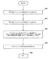
図5A及び図5Bは、一実施形態による、アダプテーション層を作成するための例示的方法のフロー図を示す部分図である。分割エンジン422は、ステップ502に示されるように、モデルコンポーネントを分析し、モデルコンポーネントをその実行可能エンティティに分割することができる。例えば、分割エンジン422は、モデルコンポーネントの依存関係グラフを構築し、又は取得することができる。依存関係グラフは、モデルコンポーネントに含まれる動作又は手順、並びに/あるいは、それらの動作又は手順間のデータ及び/又は制御の依存関係に関する情報を含む場合がある。
5A and 5B are partial views showing a flow chart of an exemplary method for creating an adaptation layer according to one embodiment. The
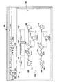
図6は、分割エンジン422によって、あるモデルコンポーネントのために構築(又は取得)される場合がある例示的依存関係グラフ600を示す概略図である。依存関係グラフ600は、モデルコンポーネントの種々の実行可能エンティティに対応する複数の部分グラフを含む場合がある。例えば、依存関係グラフ600は、初期化部分グラフ602、リセット部分グラフ604、終了部分グラフ606、及び、2つのタスクベースの部分グラフ608、610を含む場合がある。各部分グラフは、1以上のエントリポイントを含む場合がある。例えば、初期化部分グラフ602は、イベントベースであってもよく、初期化イベントのエントリポイント612を含む場合がある。リセット部分グラフ604は、イベントベースであってもよく、リセットイベントのエントリポイント614を含む場合がある。終了部分グラフ606は、イベントベースであってもよく、終了イベントのエントリポイント616を含む場合がある。第1のタスク部分グラフ608は、タスク識別子0(tid0)が割り当てられたタスクによって実行される場合がある。このタスクtid0は、例えば2秒ごとに周期的に実行される場合がある。第2のタスク部分グラフ610は、タスク識別子1(tid1)が割り当てられたタスクによって実行される場合があり、例えば1秒ごとに周期的に実行される場合がある。これらの部分グラフは、各自の実行可能エンティティの動作を表す1以上のノードをさらに含む場合があり、ノードは、実行フローを表す弧によって相互接続される場合がある。
FIG. 6 is a schematic diagram showing an
例えば、初期化部分グラフ602は、弧624〜626によって相互接続されたノード620〜623を含む場合がある。リセット部分グラフ604は、ノード628〜630及び弧632、633を含む場合がある。終了部分グラフ606は、ノード634〜636及び弧638、639を含む場合がある。第1のタスク部分グラフ608は、ノード640〜645及び弧646〜651を含む場合がある。第2のタスク部分グラフ610は、ノード646〜651及び弧652〜656を含む場合がある。
For example, the
部分グラフによって受け取られ又は生成されたデータは、依存関係グラフ上に表されることができる。例えば、初期化部分グラフ602のノード622は、破線矢印654で示されるように、メモリ、例えばNVRAMからデータを読み出し、破線矢印656で示されるように、step_2s部分グラフ608のノード643にデータを提供することができる。また、リセット部分グラフ604のノード630は、破線矢印657で示されるように、メモリ、例えばNVRAMからデータを読み出し、破線矢印658で示されるように、第1のタスク部分グラフ608のノード643にデータを提供することができる。ノード643は、破線矢印660で示されるように、終了部分グラフ606のノード636にデータを提供することができる。第1のタスク部分グラフ608のノード640は、破線矢印662で示されるように、依存関係グラフ600の外部のエンティティからデータ、例えば入力1を受け取ることができる。第2のタスク部分グラフ610のノード646は、破線矢印664で示されるように、依存関係グラフ600の外部のエンティティからデータ、例えば入力1を受け取ることができる。さらに、第1のタスク部分グラフ608のノード645及び第2のタスク部分グラフ610のノード651は、破線矢印666及び668で示されるように、依存関係グラフ600の外部のエンティティにデータを提供することができる。
The data received or generated by the subgraph can be represented on the dependency graph. For example,
図6の依存関係グラフ600は例示を目的とするものであり、他のグラフ及び/又はテキスト表現が構築され、及び/又は評価されてもよいものと理解すべきである。
It should be understood that the
分割エンジン422は、依存関係グラフ600を調べることによって、モデルコンポーネントの種々の実行可能エンティティを識別することができる。例えば、何れの他の部分グラフとも独立した部分グラフ、例えば、別の部分グラフへの弧を有しない部分グラフは、実行可能エンティティとして識別されることができる。
The
一部の実施形態では、依存関係グラフ600は、IRビルダー420によって構築される場合がある。
In some embodiments, the
図5に戻ると、分割エンジン422は、ステップ504に示されるように、例えば依存関係グラフ600を分析することによって、モデルコンポーネントの実行可能エンティティの調節可能な属性を識別することができる。調節可能な属性には、モデルコンポーネントの実行可能エンティティのエントリポイント、実行可能エンティティによって使用されるサービス、及び実行可能エンティティによって処理される入力データが含まれ得る。また、分割エンジン422は、ステップ506に示されるように、モデルコンポーネントが当初設計されたときにエントリポイントに関連付けられた呼び出しスタイル、及び、実行可能エンティティによって使用されるサービスのスタイルを識別することができる。分割エンジン422は、依存関係グラフ600を調べることによって、呼び出しスタイルを識別することができる。例えば、依存関係グラフ600は、部分グラフ602、604及び606に対応する実行可能エンティティは、イベントベースである一方、部分グラフ608及び610に対応する実行可能エンティティは、周期的タスクベースであることを示している。
Returning to FIG. 5, the
分割エンジン422は、ステップ508に示されるように、実行可能エンティティのエントリポイント間に何らかの関係、制約、又は制限が存在するか否かを判定することができる。例えば、部分グラフ608及び610に関連するタスクを調べることによって、分割エンジン422は、タスクtid1は1秒のサンプル時間で実行される一方、タスクtid0は2秒のサンプル時間で実行されることを決定する場合がある。分割エンジン422は、タスクtid1は、タスクtid0の2倍の速度で実行される必要があることを結論付けることができる。分割エンジン422は、決定された関係、制約、又は制限をメモリに記憶することができる。
The
関係又は制約の他の例としては、次が挙げられる。
1.タスクAは、タスクBが開始(又は完了)する前(又は後)に開始されなければならない。
2.タスクAとタスクBは、相互排他的でなければならない。
3.タスクAは、他のすべてのタスクが開始(又は完了)する前(又は後)に開始(又は終了)されなければならない。
4.第1グループのタスクは、第2グループのタスクが開始(又は完了)する前(又は後)に開始(又は完了)されなければならない。
5.第1グループのタスクと第2グループのタスクは、相互排他的でなければならない。
6.タスクAは、タスクBよりも優先することができる。
7.タスクAは、優先不可である。
8.メモリ読み取りは、所与のタスク内で、又は2以上のタスク間で、書き込みよりも前に行われなければならない。
9.あらゆる読み込みの後に書き込みが行われなければならない。
Other examples of relationships or constraints include:
1. 1. Task A must be started before (or after) task B starts (or completes).
2. Task A and task B must be mutually exclusive.
3. 3. Task A must be started (or finished) before (or after) all other tasks have started (or completed).
4. The tasks of the first group must be started (or completed) before (or after) the tasks of the second group are started (or completed).
5. The tasks of the first group and the tasks of the second group must be mutually exclusive.
6. Task A can take precedence over task B.
7. Task A cannot be prioritized.
8. Memory reads must occur within a given task, or between two or more tasks, prior to writing.
9. A write must be made after every read.
また、分割エンジン422は、ステップ510に示されるように、モデルコンポーネントの実行可能エンティティのスケジュールされた実行と、実行可能エンティティとのデータ通信又は実行可能エンティティ間のデータ通信のスケジュールとの関係を決定することができる。例えば、データスケジューリング調整エンジン432は、実行可能エンティティを分析し、実行可能エンティティが、例えば、Inportブロック、データ記憶メモリ読み取りブロック、定数ブロック又は他のソースブロックのようなモデル要素のデータ入力によって示されるような入力データを使用することを決定する場合がある。
The
分割エンジン422はさらに、ステップ512に示されるように、実行可能エンティティを分析し、実行可能エンティティがサービスを使用する否かを判定することができる(図5B)。実行可能エンティティによって使用されるサービスの例としては、計時サービス、エラー処理サービス、及びデータ転送サービスが挙げられる。例えば、分割エンジン422は、実行可能エンティティが、実行時の現在時刻、又は、例えばデルタタイム値のような最後の実行からの時間を使用することを決定する場合がある。場合によっては、分割エンジン422は、実行可能エンティティが、サービスとしてデータを取得し、別の実行可能エンティティと共有されたデータを読み出し及び/又は書き込みすること等を決定する場合がある。
The
さらに、データスケジューリング調整エンジン432は、ステップ514に示されるように、実行可能エンティティのうちの1以上について、データ待ち時間スキームを決定することができる。データ待ち時間スキームは、実行可能エンティティの呼び出しからその実行可能エンティティによって使用される入力データの読み出しまでの間の待ち時間を示すことができる。例えば、あるコンポーネントが、単位時間(例えば、秒、ミリ秒、マイクロ秒等)当たり一回実行されるようにスケジューリングされた速度ベースの実行可能エンティティを含み、各実行時に、実行可能エンティティが、新しい入力データを受け取るものと仮定する。データスケジューリング調整エンジン432は、実行可能エンティティの呼び出しからその新しい入力データの読み出しまでの間の許容待ち時間を決定し、又は読み出すことができる。また、データスケジューリング調整エンジン432は、実行可能エンティティの実行が完了したときと、実行可能エンティティによって生成された出力データが利用可能になるときとの間の許容待ち時間を決定し、又は読み出すことができる。一部の実施形態では、データスケジューリング調整エンジン432は、入力データ及び出力データに対して、1以上のデフォルト待ち時間値を使用する場合がある。一部の実施形態では、デフォルト待ち時間値は、ユーザ指定の値で置換される場合がある。例えば、ユーザ設定可能な待ち時間オプションが提供される場合があり、所望の値が、プログラムによって、又はオプション設定ダイアログの1以上のエントリを通じて指定される場合がある。種々の許容可能な待ち時間は、モデルコンポーネントについての待ち時間スキームとして編成される場合があり、待ち時間スキームは、アダプテーション層に含められる場合がある。
In addition, the data scheduling coordination engine 432 can determine the data latency scheme for one or more of the executable entities, as shown in
一部の実施形態では、実行可能エンティティは、データスケジューリング調整エンジン432によって得られる待ち時間挙動を指定することができる。 In some embodiments, the executable entity can specify the latency behavior obtained by the data scheduling coordination engine 432.
実行可能エンティティにより許容される実行可能エンティティの実行から入力データの読み出し若しくは出力データの発行までの間の待ち時間が長いほど、実行可能エンティティの実行は、より効率的になる。例えば、待ち時間が長くなるほど、より多くの並列性が使用される場合がある。 The longer the wait time between the execution of the executable entity and the reading of the input data or the issuance of the output data allowed by the executable entity, the more efficient the execution of the executable entity. For example, the longer the latency, the more parallelism may be used.
アダプテーション層ビルダー424は、ステップ516に示されるように、モデルコンポーネントのためのアダプテーション層を構築することができる。一部の実施形態では、アダプテーション層は、例えばコマンドに応答してプログラムによって、モデルコンポーネントのために構築される場合がある。例えば、ユーザは、アダプテーション層を構築するためのコマンドをCLIに入力することができる。一部の実施形態では、モデルコンポーネントにプロパティが関連付けられる場合があり、アダプテーション層は、例えばTrue又はFalseのような設定値に基づいて自動的に作成される場合がある。プロパティの値は、プログラムによって指定されてもよいし、あるいは、モデルコンポーネントに関連付けられたオプション設定ダイアログの1以上のエントリによって指定されてもよい。一部の実施形態では、アダプテーション層は、モデルコンポーネントが例えば後の再利用に備えてライブラリに保存される場合に、構築されることがある。アダプテーション層は、モデルコンポーネントの種々の実行可能エンティティのエントリポイントのアクセスポイントを含む場合がある。また、アダプテーション層は、実行可能エンティティの実行に関する制約、関係、又は制限、並びにモデルコンポーネントによって受信された入力データ及びモデルコンポーネントによって生成された出力データについての1以上のデータ待ち時間スキームに関する情報を含む場合がある。
The
また、一部の実施形態では、アダプテーション層は、計時サービスやデルタタイムサービスのような、実行可能エンティティによって使用される種々のサービスに関する情報を含む場合がある。一部の実施形態では、アダプテーション層は、計時サービスやデルタタイムサービスのような1以上のサービスを、実行可能エンティティに提供することができる。 Also, in some embodiments, the adaptation layer may include information about various services used by executable entities, such as timekeeping services and delta time services. In some embodiments, the adaptation layer can provide one or more services, such as timekeeping services and delta time services, to executable entities.
アダプテーション層ビルダー424は、ステップ518に示されるように、モデルコンポーネントの第2の表示形式を表示することができる。例えば、アダプテーション層ビルダー424は、例えばモデルエディタウインドウのキャンバス上に表示されるようなモデルコンポーネントのグラフィカル表現を有する1以上のアクセスポイントを有するアダプテーション層インターフェースを含む場合がある。アダプテーション層インターフェースなしで表示されたモデルコンポーネントは、モデルコンポーネントの第1の表示形式である場合がある。第1の表示形式のモデルコンポーネントと第2の表示形式のモデルコンポーネントはいずれも、実行可能である場合がある。
The
終了ステップ520に示されるように、その後、処理は完了する場合がある。
The process may then complete, as shown in
図7A〜図7Cは、一実施形態による、アダプテーション層を使用するための例示的方法を示すフロー図の部分図である。 7A-7C are partial views of a flow chart illustrating an exemplary method for using the adaptation layer according to one embodiment.
アダプテーション層が作成されたときに対象となったモデルコンポーネントは、親モデル又は親モデルコンポーネントに含められてもよい。モデルアダプタ412は、ステップ702に示されるように、アダプテーション層の1以上のアクセスポイントを親モデル又は親モデルコンポーネントの中に公開する指示を受け取る場合がある。この指示は、ユーザが、例えばテキスト又はグラフィックによって指定することができる。例えば、ユーザは、例えばマウスクリック又は他のコマンドを用いて、モデルコンポーネントを選択することができる。これに応答して、モデルコンポーネントに対して使用可能なコマンドのリストを含むダイアログのようなユーザーインターフェースウィンドウが、表示される場合がある。リストに含まれるコマンドの1つは、「アダプテーションインタフェースの構築」コマンドである。「アダプテーションインターフェースの構築」コマンドの選択に応答して、ポップアップダイアログのようなウィンドウが、モデルエディタウィンドウに表示される場合がある。
The model component targeted when the adaptation layer was created may be included in the parent model or parent model component. The
図8は、一実施形態による、アダプテーションインターフェースを構築する際に使用される例示的ウィンドウ800を示す概略図である。ウィンドウ800は、ポップアップダイアログの形を有する場合があり、モデルコンポーネントのアダプテーション層のアクセスポイントに関する種々の指示を受けとるための複数のデータエントリフィールドを含む場合がある。一部の実施形態では、ダイアログ800は、モデルコンポーネントの各実行可能エンティティについて1以上のエントリを含む場合がある。これらのエントリは、各実行可能エンティティのアクセスポイントを公開すべきか否か、及び、アクセスポイントを公開すべき場合、そのアクセスポイントの呼び出しスタイル、に関するテキスト情報を受け取る場合がある。選択されたアクセスポイントは、現在の階層レベルで公開されてもよいし、何らかの他の階層レベルで公開されてもよく、又は別のモデル場所で公開されてもよい。
FIG. 8 is a schematic diagram showing an
例えば、ダイアログ800は、実行可能エンティティを初期化するためのエントリ802を含む場合がある。エントリ802は、現在の階層レベルから初期化実行可能エンティティを呼び出す際に使用されるアクセスポイントを公開するか否かの指示を受け取るため、及びその初期化実行可能エンティティを呼び出すために使用される呼び出しスタイルに関する情報を受け取るための、テキストボックス804を含む場合がある。一部の実施形態では、テキストボックス804は、ドロップダウン矢印806を含む場合があり、これが選択された場合、現在の階層レベルから初期化実行可能エンティティを呼び出すために使用可能な呼び出しスタイルのリストが表示される場合がある。表示することができる呼び出しスタイルの例としては、エッジトリガー、ファンクションコール、及び暗黙的タスクが挙げられる。エッジトリガーは、(例えば、0から1へ)立ち上がる及び/又は(例えば、1から0へ)立ち下がる制御信号、イベント又は他のデータを使用した呼び出しスタイルを意味する場合がある。ファンクションコールは、関数を呼び出す(例えば、コールする)呼び出しスタイルを意味する場合がある。タスクという用語は、例えば時間ベースのような周期性、あるいは例えば初期化、リセット、及び終了のような非周期性を有する、アクセスポイントの属性を意味する場合がある。暗黙的タスクは、アクセスポイントが、次に高い階層レベルの各実行可能エンティティに公開されるべきではないこと、及び、アクセスポイントが、代わりに、同じタスク属性を有する別の実行可能エンティティのアクセスポイントと暗黙的に結合される場合があることを意味する場合がある。他の呼び出しスタイルが表示されてもよいものと理解すべきである。
For example,
エントリ802は、初期化実行可能エンティティのアクセスポイントを公開するとともに、それをエッジトリガ呼び出しスタイルに関連付けるように構成されている。ダイアログ800は、リセット実行可能エンティティのエントリ808をさらに含む場合があり、エントリ808は、ドロップダウン矢印812を有するテキストボックス810を含む場合がある。エントリ808は、リセット実行可能エンティティのアクセスポイントを公開するとともに、それをエッジトリガ呼び出しスタイルに関連付けるように構成されている。ダイアログ800は、終了実行可能エンティティのエントリ814をさらに含む場合があり、エントリ814は、ドロップダウン矢印818を有するテキストボックス816を含む。エントリ814は、終了実行可能エンティティのアクセスポイントを公開するとともに、それをエッジトリガ呼び出しスタイルに関連付けるように構成されている。ダイアログ800は、Step_1s実行可能エンティティのエントリ820をさらに含み、エントリ820は、ドロップダウン矢印824を有するテキストボックス822を含む場合がある。エントリ822は、Step_1s実行可能エンティティのアクセスポイントを公開するとともに、それをファンクションコール呼び出しスタイルに関連付けるように構成されている。ダイアログ800は、Step_2s実行可能エンティティのエントリ826を含む場合があり、エントリ826は、ドロップダウン矢印830を有するテキストボックス828を含む。エントリ826は、Step_2s実行可能エンティティのアクセスポイントを公開しないように構成され、代わりに、このアクセスポイントを、親モデル又は親モデルコンポーネントの1以上のアクセスポイントと集約するように構成されている。
親モデルにおいてエントリーポイントが、例えば暗黙的にエクスポートされた場合、例えばアダプテーション層では、実行頻度及びデータ依存関係情報を分析することによって、実行シーケンスが、自動的に決定される場合がある。例えば、実行可能エンティティは、親モデルにおけるものと同じ実行頻度を有するタスク内で実行される場合がある。タスクの内部で、実行可能エンティティは、データ又は制御の依存関係に基づいて実行される場合があり、例えば、実行可能エンティティは、その実行可能エンティティにデータを提供するモデル要素の後、及び、その実行可能エンティティによって計算された結果を使用するモデル要素の前に実行される場合がある。 If the entry points are implicitly exported in the parent model, for example in the adaptation layer, the execution sequence may be determined automatically by analyzing the execution frequency and data dependency information. For example, an executable entity may run within a task that has the same execution frequency as that in the parent model. Inside a task, an executable entity may be executed based on data or control dependencies, for example, an executable entity is after and after a model element that provides data to that executable entity. It may be executed before a model element that uses the result calculated by the executable entity.
一部の実施形態では、実行可能エンティティは、ファンクションコール又はメッセージのような1以上の明示的イベント、あるいは、トリガ信号又は周期的タイマーのような1以上の暗黙的イベントによってトリガー駆動される場合がある。 In some embodiments, the executable entity may be triggered by one or more explicit events, such as a function call or message, or one or more implicit events, such as a trigger signal or a periodic timer. be.
図7Aに戻り、アダプテーション層ビルダー424は、ステップ704に示されるように、親モデル又は親モデルコンポーネントに含まれるモデルコンポーネントのためのアダプテーション層インターフェースを構築することができる。アダプテーションインターフェースは、例えば初期化実行可能エンティティ、リセット実行可能エンティティ、終了実行可能エンティティ、及びStep_1s実行可能エンティティのためのアクセスポイント(図8参照)のような選択されたアクセスポイントを、公開することができる。集約エンジン428は、ステップ706に示されるように、集約に備えてマークされた種々のアクセスポイントを集約することができる。例えば、これらのアクセスポイントは、モデル階層のより高いレベルのアクセスポイントと結合され、より高い階層レベルで公開される場合がある。
Returning to FIG. 7A, the
モデルアダプタ412は、ステップ708に示されるように、親モデル又は親モデルコンポーネントからアダプテーションインターフェースの公開されたアクセスポイントへの接続が行われたことを検出することができる。接続が検出された場合、マッピングエンジン426は、ステップ710に示されるように、親モデル又は親モデルコンポーネント(ユーザが指定してもよい)で使用される機能及び呼び出しスタイルを、各実行可能エンティティのエントリポイントにバインドすることができる。ループバック矢印712で示されるように、接続の検出、並びに、機能及び呼び出しスタイルのバインドは、他の公開されたアクセスポイントに接続が行われたときに繰り返される場合がある。モデルアダプタ412は、例えば親モデル又は親モデルコンポーネントの種々のモデル要素によって表されるような、親モデル又は親モデルコンポーネントに含まれるロジックを分析し、モデルコンポーネントの実行可能エンティティの実行を呼び出すことができる。
The
アダプテーション層の調節可能な属性は、公開された調節可能な属性に接続されたスケジューリングロジックその他のロジック以外の方法で設定又は構成されてもよいし、あるいは、そのようなロジックを含む他の方法で設定又は構成されてもよい。 The adjustable attributes of the adaptation layer may be set or configured in any way other than the scheduling logic or other logic connected to the exposed adjustable attributes, or in any other way that includes such logic. It may be set or configured.
一部の実施形態では、アダプテーション層ビルダー424(又はIRビルダー420)は、モデルコンポーネントを含む親モデル又は親モデルコンポーネントのためのコールグラフを構築することができる。コールグラフは、親モデル又は親モデルコンポーネントとモデルコンポーネントとの間の呼び出し関係を表すことができる。コールグラフは、親モデル又は親モデルコンポーネントがモデルコンポーネントの実行可能エンティティを呼び出す態様を示している。コールグラフは、親モデル又は親モデルコンポーネントがモデルコンポーネントの実行可能エンティティを呼び出すために使用する特定の呼び出しスタイルを示す場合がある。例えば、コールグラフは、親モデル又は親モデルコンポーネントが、ファンクションコールを使用して第1の実行可能エンティティを呼び出し、トリガーを使用して第2の実行可能エンティティを呼び出すことを示す場合がある。 In some embodiments, the adaptation layer builder 424 (or IR builder 420) can build a call graph for a parent model or parent model component that includes a model component. The call graph can represent the calling relationship between the parent model or parent model component and the model component. The call graph shows how the parent model or parent model component calls the executable entity of the model component. The call graph may show the particular calling style that the parent model or parent model component uses to call the executable entity of the model component. For example, a call graph may indicate that a parent model or parent model component uses a function call to call a first executable entity and a trigger to call a second executable entity.
モデルアダプタ412は、ステップ716(図7B)に示されるように、親モデル又は親モデルコンポーネントのロジックによる実行可能エンティティのスケジューリングと、モデルコンポーネントの実行可能エンティティの実行のために決定された関係、制約、又は制限との間に、矛盾が存在するか否かを判定することができる。矛盾が検出された場合、モデルアダプタ412は、ステップ718に示されるように、エラー又は警告を発行することができる。例えば、UIエンジン402は、モデルエディタウィンドウ100上に、エラー又は警告メッセージを表示する場合がある。
As shown in step 716 (FIG. 7B), the
アダプテーション層は、ステップ720に示されるように、モデルコンポーネントの種々の実行可能エンティティを実行するためのスケジュールを生成することができる。スケジュールを決定するために、アダプテーション層は、
1.親モデル又は親モデルコンポーネントによって実施される呼び出しスタイル(複数可)、及びモデルコンポーネントの実行可能エンティティの呼び出しスタイル(複数可);及び
2.モデルコンポーネントの実行可能エンティティの実行を呼び出す、親モデル又は親モデルコンポーネントに含まれるスケジューリングロジック
を考慮することができる。
The adaptation layer can generate a schedule for executing the various executable entities of the model component, as shown in
1. 1. The call style (s) implemented by the parent model or parent model component, and the call style (s) of the executable entity of the model component; and 2. You can consider the parent model or the scheduling logic contained in the parent model component that calls the execution of the executable entity of the model component.
アダプテーション層によって生成されたスケジュールは、モデルコンポーネントの呼び出しスタイルとは対照的に、親モデル又は親モデルコンポーネントの呼び出しスタイルに適用される場合がある。例えば、親モデルがファンクションコール呼び出しスタイルを実施し、モデルコンポーネントが速度ベースのマルチタスク型呼び出しスタイルを実施している場合、アダプテーション層によって生成されたスケジュールは、種々のファンクションコールをスケジューリングすることができる。アダプテーション層は、親モデルのファンクションコールに応答して、速度ベースのマルチタスク型呼び出しスタイル用に当初定義されたモデルコンポーネントの実行可能エンティティの呼び出しも処理する。 The schedule generated by the adaptation layer may be applied to the parent model or the parent model component's calling style, as opposed to the model component's calling style. For example, if the parent model implements a function call call style and the model component implements a speed-based multitasking call style, the schedule generated by the adaptation layer can schedule various function calls. .. The adaptation layer also handles calls to the executable entities of the model components originally defined for the speed-based multitasking calling style in response to the parent model's function calls.
アダプテーション層は、ステップ722に示されるように、実行可能エンティティによって使用されるサービスが、例えば現在の階層レベルから、コンポーネントに提供されるか否かを判定することができる。例えば、モデルコンポーネントが、実行中に計時サービスを使用すると仮定する。さらに、モデルコンポーネントは、モデルコンポーネントがリアルタイムプラットフォーム又は環境上でどのように実行されるかをシミュレートする形で実行されているものと仮定する。ユーザは、リアルタイムプラットフォーム又は環境によって計時サービスをモデル化するロジックを有する場合がある。例えば、ユーザは、リアルタイムプラットフォーム又はリアルタイムの計時サービスをシミュレートするように構成されたカウンタ又はタイマブロックを、現在の階層レベルに有する場合がある。アダプテーション層は、カウンタ又はタイマブロックが、実行可能エンティティによって使用される計時サービスをシミュレートするものと判定することができる。
The adaptation layer can determine whether the services used by the executable entity are provided to the component, eg, from the current hierarchy level, as shown in
実行可能エンティティによって使用される1以上のサービスが、例えば現在の階層レベルに又は別の階層レベル若しくはモデル位置に、明示的に定義され又は提供されていない限り、アダプテーション層は、ステップ724に示されるように、実行可能エンティティのための種々のサービスを提供することができる(図7C)。一部の実施形態では、アダプテーション層は、モデリング環境400と協働して、種々のサービスを提供することができる。例えば、シミュレーションエンジン410は、計時サービス、デルタタイムサービス、及びエラー処理サービスを含む場合がある。アダプテーション層は、それらのサービスを使用する実行可能エンティティへのそれらのサービスの提供を調整することができる。一部の実施形態では、アダプテーション層は、ステップ726に示されるように、明示的に定義され、又は暗黙的に生成されたサービスのスタイルを、実行可能エンティティによって必要とされるスタイルに変換することができる。
The adaptation layer is shown in
ステップ728に示されるように、データスケジューリング調整エンジン432は、親モデル又は親モデルコンポーネントとモデルコンポーネントとの間、あるいは、モデルコンポーネントの種々の実行可能エンティティ間でデータを交換するためのスケジュールを決定することができ、スケジュールは、モデルコンポーネントの実行可能エンティティを実行するためのスケジュールとの間で調整される。データスケジューリング調整エンジン432は、アダプテーション層から待ち時間スキームを読み出し、それを、実行可能エンティティの実行を呼び出す親モデル又はモデルコンポーネントのロジックに対して評価することができる。データスケジューリング調整エンジン432は、データ交換が、実行可能エンティティの実行との間で調整され、指定された待ち時間スキームを満たすようにするために、入力データをモデルコンポーネントにいつ提供する必要があるか、及び出力データをモデルコンポーネントからいつ読み出す必要があるかを、決定することができる。
As shown in
一部の実施形態では、モデルコンポーネントによって使用される入力データ、及び、モデルコンポーネントによって生成された出力データを記憶する種々のモデルコンポーネントのために、データバッファが確立される場合がある。モデルコンポーネントがデータ転送をサービスとして要求した場合、モデルコンポーネントそれ自体は、データバッファを確立できない場合がある。代わりに、種々の要求データ転送サービスが、説明したように、現在の階層レベルに提供される場合がある。 In some embodiments, data buffers may be established for the input data used by the model components and for the various model components that store the output data produced by the model components. If the model component requests data transfer as a service, the model component itself may not be able to establish a data buffer. Alternatively, various request data transfer services may be provided at the current hierarchy level, as described.
モデルコンポーネントの実行可能エンティティは、種々のアクセスメソッドを使用して、バッファから入力データを獲得し、出力データをバッファに記憶することができる。データスケジューリング調整エンジン432は、そのようなバッファとの間の読み出し及び書き込みのスケジュールを確立することができる。スケジュールは、モデルコンポーネントの実行可能エンティティの実行スケジュールと同期させることができ、モデルコンポーネントの入力データ転送及び出力データ転送のために確立された待ち時間スキームを満たすことができる。モデルコンポーネントとの間のデータ転送のスケジューリングは、モデルコンポーネントのモデル要素間のデータ依存関係の関数であってもよい。例えば要求されたデータ転送サービスを提供するために、データ転送スケジュールは、アダプテーション層に提供され、アダプテーション層は、データ転送スケジュールにしたがってアクセスメソッドを呼び出す場合がある。 The executable entity of the model component can use various access methods to get input data from the buffer and store the output data in the buffer. The data scheduling coordination engine 432 can establish read and write schedules to and from such buffers. The schedule can be synchronized with the execution schedule of the model component's executable entity and can meet the latency scheme established for the model component's input and output data transfers. Scheduling data transfer to and from the model component may be a function of the data dependency between the model elements of the model component. For example, in order to provide the requested data transfer service, the data transfer schedule may be provided to the adaptation layer, which may call the access method according to the data transfer schedule.
全てのデータ転送情報が使用可能である場合、コンパイル中にモデルコンパイラ416によって、データバッファが割り当てられる場合がある。モデルコンパイラ416がコンパイル中にデータバッファを割り当てるための十分な情報を欠いている場合(例えば、データ転送の挙動が不明であることから)、例えば初期化フェイズ中は、割当てが、延期される場合がある。一部の実施形態では、データバッファの割り当ては、モデルの実行中に実施される場合がある。さらに、アダプテーション層は、データバッファにアクセスするためのインターフェースを提供する場合がある。
If all data transfer information is available, the
シミュレーションエンジン410は、ステップ730に示されるように、モデルコンポーネントを含む親モデル又は親モデルコンポーネントを実行することができる。
The
モデル実行
シミュレーションエンジン410は、モデルコンポーネントが当初設計されたときの呼び出しスタイルとは異なる呼び出しスタイルを使用してそのモデルコンポーネントを呼び出す、モデルについての種々の実行命令を生成することができる。実行命令の生成及びモデルの実行は、初期化フェイズ、シミュレーション(又は実行)フェイズ、0、1若しくは2以上のリセットフェイズ、及び終了フェイズのような複数のフェイズを含む場合がある。モデルの実行には、入力データを受け取り、処理すること、及び出力データを生成することが含まれる場合がある。一部の実施形態では、モデルの実行は、例えばシミュレーション時間のようなある期間にわたって実行される場合があり、この期間は、ユーザ指定であってもよいし、機械指定であってもよい。シミュレーション時間は、論理的実行時間であり、シミュレーション開始時刻から始まり、シミュレーション終了時刻に終了する場合がある。シミュレーション開始時刻とシミュレーション終了時刻との間の一連の時点(これらの時点は、シミュレーション時間ステップと呼ばれることがある)で、モデルの種々のモデル要素の状態、入力及び出力が計算される場合がある。時間ステップのサイズは、固定されていても変化されてもよく、モデルの実行の際に選択され、使用される特定のソルバー418によって決定される場合がある。シミュレーション時間の全体にわたって、実行命令は、シミュレーションエンジン410によって生成される場合がある。
The model
初期化フェイズ
初期化フェイズは、モデルの実行の開始を特徴づけることができ、種々の命令をコンパイルし、リンクすることを含む場合がある。初期化フェイズは、データ構造を準備し、パラメータを評価すること、ブロック特性を構成し、伝搬すること、ブロック接続を決定すること、及び、ブロック削減やブロック挿入を実施することを含む場合がある。データ構造の準備及びパラメータの評価の結果として、初期化フェイズで使用するための1以上のデータ構造の作成及び初期化がもたらされる場合がある。モデルの種々のブロックについて、あるメソッドは、それらのブロックに、ブロックのすべてのパラメータを強制的に評価させることができ、このメソッドは、モデルの各ブロックについて呼び出される場合がある。未解決のパラメータがある場合、実行エラー及び/又はコンパイルエラーが投じられる場合がある。ブロック及びポート/信号特性の構成及び伝搬中に、各ブロック及び/又はポート/信号のコンパイル済属性(データ次元、データ型、複雑度、サンプルモード、及びサンプル時間など)が、対応する挙動、並びに、所与のブロック及び/又はポート/信号に接続されたブロック及び/又はポート/信号の属性に基づいて、設定される場合がある。この属性設定は、あるプロセスを通して実施される場合があり、当該プロセスの中で、あるブロックから次に続く信号、データフロー、制御、状態、物理的、メッセージ又は他の接続性へと、ブロックの挙動は、モデル全体に「波及」する。
Initialization Phase The initialization phase can characterize the start of execution of the model and may include compiling and linking various instructions. The initialization phase may include preparing data structures, evaluating parameters, configuring block characteristics, propagating, determining block connections, and performing block reductions and block insertions. .. Data structure preparation and parameter evaluation may result in the creation and initialization of one or more data structures for use in the initialization phase. For various blocks of the model, a method can force those blocks to evaluate all the parameters of the block, and this method may be called for each block of the model. If there are unresolved parameters, execution errors and / or compilation errors may be thrown. During the configuration and propagation of block and port / signal characteristics, each block and / or port / signal's compiled attributes (such as data dimension, data type, complexity, sample mode, and sample time) have the corresponding behavior, as well as , May be set based on the attributes of the block and / or port / signal connected to a given block and / or port / signal. This attribute setting may be performed through a process, within which a block's signals, data flows, controls, states, physicals, messages or other connectivity. The behavior "spreads" throughout the model.
このプロセスは、推論と呼ばれることがあり、その一実施形態が、伝搬である。ブロック(又はポート)挙動が明示的に指定されたブロックの場合、伝搬は、ブロック(又はポート)の属性が、それに接続されたブロック(又はポート)の属性と互換性を有することを確保するのに役立つ。もし互換性が無ければ、シミュレーションエンジン1310によって警告又はエラーが発行され、ユーザーインターフェースエンジン402によってユーザに対して表示される。多くのブロック(又はポート)は、幅広い属性と互換性を有するように実施されることができる。そのようなブロック(又はポート)は、自分自身の挙動を、自分自身に接続されたブロック(又はポート)の属性にしたがって、適合させることができる。ブロックの正確な実施形態は、そのブロックが配置されるモデルに基づいて選択される場合がある。このステップには、すべての速度遷移が決定論的結果をもたらすこと、及び、適当な速度遷移ブロック及び/又は遅延ブロックが使用されていることを検証すること、のような他の態様が含まれ得る。
This process is sometimes called inference, one embodiment of which is propagation. For blocks whose block (or port) behavior is explicitly specified, propagation ensures that the attributes of the block (or port) are compatible with the attributes of the block (or port) connected to it. Useful for. If incompatible, the
初期化フェイズは、実際のブロック接続を決定することもできる。例えば、仮想ブロックは、モデルの実行において意味役割を何も演じない場合がある。このステップでは、仮想ブロックは、最適化によって消去され、例えば除去される場合があり、残りの非仮想ブロックが、互いに適当に再接続される場合がある。実際のブロック接続を有するモデルのこのコンパイル済バージョンは、この時点から、実行プロセスで使用することができる。モデル内でブロックを相互接続する仕方が必ずしも、ブロックメソッドが実行される順序を定義するとは限らない。一部の実施形態では、ブロックメソッドには、出力方程式、微分方程式及び更新方程式が含まれる場合がある。 The initialization phase can also determine the actual block connection. For example, virtual blocks may play no semantic role in the execution of the model. In this step, the virtual blocks may be erased by optimization, eg removed, and the remaining non-virtual blocks may be properly reconnected to each other. This compiled version of the model with the actual block connection can be used in the execution process from this point on. The way blocks are interconnected in the model does not necessarily define the order in which the block methods are executed. In some embodiments, the block method may include output equations, differential equations and update equations.
初期化フェイズ中に、ブロックサンプル時間が決定される場合もある。ブロックのサンプル時間は、例えばそのブロックのサンプル時間パラメータを設定することによって、明示的に設定されてもよいし、あるいは、そのブロックのタイプ又はモデル内のそのブロックのコンテキストに基づいて、暗黙的に決定されてもよい。サンプル時間パラメータは、ベクトル[TS、TO]であってもよい。ここで、TSはサンプリング周期であり、TOは初期時間オフセットである。初期化中に、モデルコンパイラ416は、種々のモデル要素のサンプル時間を、明示的サンプル時間を有するモデル要素については、モデル要素のサンプル時間パラメータから決定し、暗黙的サンプル時間を有するモデル要素については、モデル要素タイプから決定する場合があり、あるいは、それらのサンプル時間を継承するモデル要素については、モデルコンテンツから決定する場合がある。コンパイルされたサンプル時間は、シミュレーションの際に、モデル要素のサンプル速度を決定する場合がある。
The block sample time may also be determined during the initialization phase. The block sample time may be set explicitly, for example by setting the block sample time parameter, or implicitly based on the block type or the block's context within the model. It may be decided. Sample time parameter vector [T S, T O] may be. Here, T S is the sampling period, T O is the initial time offset. During initialization, the
選択されたソルバー418は、モデルのシミュレーションのためのシミュレーション時間ステップのサイズを決定することができ、これらのシミュレーション時間ステップは、モデルのブロックのサンプル時間に対応するように選択される場合がある。シミュレーション時間ステップが、あるブロックのサンプル時間に一致すると、サンプル時間ヒットが発生し、そのブロックは、そのシミュレーションステップ中の実行に備えてスケジューリングされる。 The selected solver 418 can determine the size of the simulation time steps for simulating the model, and these simulation time steps may be selected to correspond to the sample time of the blocks in the model. When a simulation time step matches the sample time of a block, a sample time hit occurs and the block is scheduled for execution during that simulation step.
ソルバー418a〜418cは、モデルの種々のブロックについて実行リストを生成することができる1以上のスケジューラを含み、又は、そのような1以上のスケジューラを取得することができる。具体的には、スケジューラは、ブロックソート済順序リスト及びメソッド実行リストを生成することができる。スケジューラは、ブロックソート済順序リスト及びメソッド実行リストを生成するために、1以上のアルゴリズムを使用する場合がある。例えば、静的スケジューラは、レートモノトニックスケジューリング(RMS:Rate Monotonic Scheduling)、EDF(EarliestDeadline First)スケジューリング、静的循環スケジューリング、又はデッドラインモノトニックスケジューリング(DMS:Deadline Monotonic Scheduling)を使用する場合がある。動的スケジューラは、イベントカレンダを使用して、タイムアウトやアラームのような将来のイベントをスケジューリングする場合がある。 Solvers 418a-418c include one or more schedulers capable of generating execution lists for various blocks of the model, or can acquire one or more such schedulers. Specifically, the scheduler can generate a block-sorted sequence list and a method execution list. The scheduler may use one or more algorithms to generate a block-sorted sequence list and a method execution list. For example, the static scheduler may use Rate Monotonic Scheduling (RMS), Earliest Deadline First (EDF) Scheduling, Static Circular Scheduling, or Deadline Monotonic Scheduling (DMS). .. The dynamic scheduler may use the event calendar to schedule future events such as timeouts and alarms.
一部の実施形態では、初期化フェイズは、初期化フェイズ中に実行することができるユーザ指定動作をさらに含む場合がある。例えば、初期化イベントに応答して条件付きで実行されるサブシステム中に指定された種々の動作は、初期化フェイズ中に実行される場合がある。 In some embodiments, the initialization phase may further include user-specified actions that can be performed during the initialization phase. For example, various actions specified in a subsystem that are conditionally executed in response to an initialization event may be performed during the initialization phase.
初期化フェイズは、1回発生する場合がある。 The initialization phase may occur once.
実行フェイズ
実行フェイズ又はシミュレーションフェイズは、初期化フェイズの後に続く場合がある。実行フェイズ中に、シミュレーションエンジン410は、シミュレーションループ又は反復ループステージに入り、その間、シミュレーションエンジン410は、入力を連続的に獲得して、シミュレーション開始時間からシミュレーション終了時間まで、特定のシミュレーション時間ステップでモデル要素の状態及び出力を計算する。各ステップにおいて、モデル要素の入力、状態、及び出力の新しい値が計算される場合があり、モデル要素は、計算された値を反映するように更新される場合がある。ステップ間の時間の長さは、ステップサイズと呼ばれる。ステップサイズは、モデルを実行するために選択されたソルバー418のタイプ、モデルの基本サンプル時間、及びモデルの連続状態がゼロ交差のような不連続性を有するか否かに依存する。シミュレーションループ又は反復ループのステップは、シミュレーション終了時刻に達するまで繰り返される場合がある。シミュレーション時間の最後に、モデル要素の入力、状態、及び出力の最終値が、モデルに反映される。一部の実施形態では、モデルは、予め設定されたシミュレーション終了時刻なしに実行される場合がある。
Execution Phase The Execution Phase or Simulation Phase may follow the Initialization Phase. During the run phase, the
リセットフェイズ(複数可)
一部の実施形態では、実行フェイズは、0、1又は2以上のリセットフェイズを含む場合がある。リセットフェイズは、システム生成動作を実行することができる暗黙的部分を含む場合がある。リセットフェイズは、ユーザ指定の(明示的)リセット動作を実行することができる明示的部分を含む場合がある。例えば、ユーザ指定の種々の動作が、リセットイベントに応答して条件付きで実行されるサブシステム中に指定される場合がある。一部の実施形態では、リセットフェイズは、明示的リセット動作のみを含む場合がある。
Reset phase (s)
In some embodiments, the execution phase may include 0, 1 or more than 2 reset phases. The reset phase may include an implicit part in which a system-generated operation can be performed. The reset phase may include an explicit part in which a user-specified (explicit) reset operation can be performed. For example, various user-specified actions may be specified in a system that is conditionally executed in response to a reset event. In some embodiments, the reset phase may include only an explicit reset operation.
実行フェイズ中に、モデルのためのコードが生成されてもよいし、生成されなくてもよい。コードが生成された場合、モデルは、加速実行モードで実行される場合がある。加速実行モードでは、モデル又はその一部が、ソフトウェアモジュール又はハードウェア記述のいずれかに変換される。このステージが実行された場合、その後に続く種々のステージは、モデルの実行の際に、生成されたコードを使用することができる。コードが生成されなかった場合、モデルは、インタープリティブモードで実行される場合がある。インタープリティブモードでは、シミュレーション時間にわたってモデルを実行するために、モデルのコンパイルされ、リンクされたバージョンが、シミュレーションエンジン410によって直接使用される場合がある。モデルのためのコードが生成された場合、必ずしもモデルが実行される必要はない。モデリング環境400内でモデルを実行する代わりに、生成されたコード434がコンパイルされ、コントローラやテストハードウェアのようなターゲット装置上に配備される場合がある。
During the execution phase, the code for the model may or may not be generated. When the code is generated, the model may run in accelerated execution mode. In accelerated execution mode, the model or part of it is transformed into either a software module or a hardware description. When this stage is executed, the various stages that follow can use the generated code when running the model. If no code is generated, the model may run in interpretive mode. In interpretive mode, a compiled and linked version of the model may be used directly by the
終了フェイズ
終了フェイズは、実行フェイズの後に続く場合がある。終了フェイズ中に、シミュレーションエンジン410は、クリーンアップ動作を実施することができる。例えば、シミュレーションエンジン410は、割り当てられたメモリを解放する場合がある。終了フェイズ中に実行される他の動作としては、内部メモリを不揮発性ランダムアクセスメモリ(NVRAM)のような不揮発性メモリに保存すること、ADC及びDACの電源をオフにすること、アクチュエータをシャットダウンすること、終了フラグを発行すること、データをデータファイルに書き出すこと、及びデータファイルを閉じることが挙げられる。
End Phase The end phase may follow the execution phase. During the end phase, the
終了フェイズは、終了フェイズ中に実行することができるユーザ指定の(明示的)終了動作をさらに含む場合がある。例えば、ユーザ指定の種々の動作が、終了イベントに応答して条件付きで実行されるサブシステムに含まれる場合がある。終了フェイズは、1回発生する場合がある。 The end phase may further include user-specified (explicit) end actions that can be performed during the end phase. For example, various user-specified actions may be included in a subsystem that is conditionally executed in response to an termination event. The end phase may occur once.
モデルは、初期化、実行、リセット、及び終了の他に、追加及び/又は他のフェイズを含むことができるものと理解すべきである。例えば、モデルは、とりわけ、ウォームスタートフェイズ、コールドスタートフェイズ、部分リセットフェイズ、ソフトリセットフェイズ、フルリセットフェイズ、ハードリセットフェイズ、正常終了フェイズ、及び緊急終了フェイズを含む場合がある。異なる初期化フェイズ、リセットフェイズ、又は終了フェイズ中に、異なる動作が実行される場合がある。例えば、緊急終了フェイズ中に実行することができる唯一の動作は、例えば、電源が失われる前に重要データを保存することである。 It should be understood that the model can include additions and / or other phases in addition to initialization, execution, reset, and termination. For example, the model may include, among other things, a warm start phase, a cold start phase, a partial reset phase, a soft reset phase, a full reset phase, a hard reset phase, a normal end phase, and an emergency end phase. Different actions may be performed during different initialization, reset, or end phases. For example, the only action that can be performed during the emergency termination phase is, for example, to save important data before power is lost.
コード発生器406は、ステップ732に示されるように、モデルコンポーネントを含む親モデル又は親モデルコンポーネントのためのコードを生成することができる。生成されたコードは、モデルコンポーネントのアダプテーション層にリンクされたユーザ指定の機能に基づいて、モデルコンポーネントの種々の実行可能エンティティを呼び出すためのスケジュールを実施することができる。生成されたコードは、モデルとモデルコンポーネントとの間のデータの交換によってモデルコンポーネントの実行可能エンティティの呼び出しを調整するコードを含む場合がある。生成されたコードは、異なる呼び出しスタイル、すなわち、親モデル又は親モデルコンポーネントで使用される呼び出しスタイルとモデルコンポーネントで使用される呼び出しスタイルのバインディングのためのコードをさらに含む場合がある。
The
コード生成は、コードが実行されることになる環境によって提供される種々のサービスを呼び出すコードを生成することをさらに含む場合がある。例えばモデリング環境のようなシミュレーション環境では、これらのサービスは、シミュレーションエンジン410によって提供される場合がある。このようなサービスの例には、データ転送、タイマー、経過時間、及びエラー処理が挙げられる。例えば、リアルタイム環境における配備のために、これらのサービスは、リアルタイムオペレーティングシステム(RTOS)によって、及び/又はハードウェアクロックのようなリアルタイム環境の1以上のハードウェア要素によって、提供される場合がある。
Code generation may further include generating code that calls various services provided by the environment in which the code will be executed. In a simulation environment, such as a modeling environment, these services may be provided by the
図9は、一実施形態による、例示的再利用環境900を示す概略図である。再利用環境900は、モデルコンポーネント902を含む場合があり、モデルコンポーネント902は、モデリング環境400を操作するユーザによって作成されたサブシステム又はサブモデルのようなグラフィカルモデルコンポーネントである場合がある。モデルコンポーネント902は、速度ベースのマルチタスク型呼び出しスタイルを使用するように当初作成されたものである場合がある。モデルコンポーネント902は、検証テストを受ける場合があり、モデルコンポーネント902の検証要件を満たすことが証明されている場合がある。モデルコンポーネント902は、モデリング環境400によって使用されるライブラリに保存される場合がある。
FIG. 9 is a schematic diagram showing an
参照符号902’で示されるモデルコンポーネント902のインスタンスは、破線矢印906で示されるように、モデルコンポーネント904(モデルコンポーネント_2)内に含まれる場合がある。インスタンス902’は、モデルコンポーネント902のコピーであってもよい。あるいは、インスタンス902’は、ライブラリに保存されることがあるモデルコンポーネント902へのライブラリリンクのようなリンクを表す場合がある。ライブラリに保存されたリンク先のモデルコンポーネント902への変更は、ライブラリリンクを介して、インスタンス902’のようなモデルコンポーネントのすべてのインスタンスによって継承されることができる。ライブラリに保存されたモデルコンポーネント902の構造及び動作は、完全に定義され、固定されることができ、コンポーネント902のあらゆるインスタンスが、その固定された構造及び動作を実施することができる。
An instance of the
モデルコンポーネント904は、モデリング環境400においてユーザによって作成されたグラフィカルモデルコンポーネントであってもよい。ただし、モデルコンポーネント904は、ファンクションコール型呼び出しスタイルを使用するように作成されたものである場合がある。ファンクションコールベースのモデルコンポーネント904において速度ベースのマルチタスクベースのモデルコンポーネントインスタンス902’を使用するために、モデルアダプタ412は、モデルコンポーネントインスタンス902’のためのアダプテーション層インターフェイス908を構築することができる。さらに、モデルコンポーネント904は、モデルコンポーネントインスタンス902’の種々の実行可能エンティティを呼び出すために、アダプテーション層インターフェース908に接続されたモデル要素910〜912で示される機能又はロジックを含む場合がある。アダプテーション層は、モデルコンポーネント904のファンクションコールに基づく呼び出しを、モデルコンポーネントインスタンス902’の速度ベースのマルチタスク型呼び出しスタイルにバインドすることができる。重要なことに、モデルコンポーネントインスタンス902’が、モデルコンポーネント904内で実行されるように修正される必要はない。例えば、速度ベースのマルチタスク型モデルコンポーネントインスタンス902’をファンクションコールモデルコンポーネント904内で実行するために、モデルコンポーネントインスタンス902’のモデル要素を追加、削除、置換、又は変更する必要はない。モデルコンポーネントインスタンス902’に変更を加える必要がないため、モデルコンポーネントインスタンス902’を再検証する必要はない。
The
モデルコンポーネント904は、破線矢印916で示されるように、モデル914(モデル_1)に含まれる場合がある。モデル914は、モデリング環境400においてユーザによって作成されたグラフィカルモデルであってもよい。モデル914は、速度ベースのマルチタスク型呼び出しスタイルを使用するように作成される場合がある。ファンクションコールベースのモデルコンポーネント904をモデル914で使用するために、モデルアダプタ412は、モデルコンポーネント904のためのアダプテーション層インターフェース918を構築することができる。さらに、モデル914は、モデルコンポーネント904の種々の実行可能エンティティを呼び出すために、アダプテーション層インターフェース918に接続されたモデル要素920及び922で示されるロジックを含む場合があり、モデルコンポーネント904は、同様に、モデルコンポーネント902’の種々の実行可能エンティティを呼び出すことができる。
The
参照符号902”で示されるモデルコンポーネント902の別のインスタンスが、破線矢印926で示されるように、別のモデル924(モデル_2)に含まれる場合がある。モデル924は、モデリング環境400においてユーザによって作成されたグラフィカルモデルであってもよい。ただし、モデル924は、エッジトリガー型呼び出しスタイルを使用するように作成されたものである場合がある。エッジトリガベースのモデル924において速度ベースのマルチタスクベースのモデルコンポーネントインスタンス902”を使用するために、モデルアダプタ412は、モデルコンポーネントインスタンス902”のためのアダプテーション層及びアダプテーション層インターフェイス928を構築することができる。一部の実施形態では、以前に作成されたアダプテーション層が、モデルコンポーネントインスタンス902”のために使用される場合がある。さらに、モデル924は、モデルコンポーネントインスタンス902”の種々の実行可能エンティティを呼び出すために、アダプテーション層インターフェース928に接続されたモデル要素930〜932で示されるロジックを含む場合がある。アダプテーション層は、モデル924のエッジトリガー型呼び出しを、モデルコンポーネントインスタンス902”の速度ベースのマルチタスク型呼び出しスタイルにバインドすることができる。この場合も、モデルコンポーネントインスタンス902”が、モデル924内で実行されるように修正される必要はない。したがって、モデルコンポーネントインスタンス902”を再検証する必要はない。
Another instance of the
図9は、モデルコンポーネント902のために生成されたコードの再利用も示している。例えば、コード発生器406は、モデルコンポーネント902のためのコード934を生成することができる。コード発生器406はさらに、モデルコンポーネントインスタンス902’を含むモデルコンポーネント904のためのコード936を生成することができる。モデルコンポーネント904に含まれるモデルコンポーネントインスタンス902’のための新しいコードを生成する代わりに、コード発生器406は、モデルコンポーネント902のために生成されたコード934を、モデルコンポーネント904のために生成されたコード936内で再利用することができる。コード発生器406は、アダプテーション層のためのコード938を生成することができ、このコード938をモデルコンポーネント904のためのコード936に含めることができる。コード発生器406はさらに、矢印940及び942で示されるように、アダプテーション層のために生成されたコード938に対する種々の呼び出し及び戻りのためのコードを生成することができる。
FIG. 9 also shows reuse of the code generated for
コード発生器406は、モデル914のためのコード944を生成することができる。モデル914に含まれるモデルコンポーネント904のための新しいコードを生成する代わりに、コード発生器406は、モデルコンポーネントインスタンス902’のために生成されたコード934を含む、モデルコンポーネント904のために生成されたコード936を再利用することができる。コード発生器406は、モデルコンポーネント904に向けて、アダプテーション層のためのコード946を生成することができる。コード発生器406はさらに、矢印948及び950で示されるように、アダプテーション層のために生成されたコード946に対する種々の呼び出し及び戻りのためのコードを生成することができる。
コード発生器406は、モデルコンポーネントインスタンス902“を含むモデル924のためのコード952を生成することができる。モデルコンポーネントインスタンス902“のための新しいコードを生成する代わりに、コード発生器406は、モデルコンポーネント902のために生成されたコード934を再利用することができる。コード発生器406は、モデルコンポーネントインスタンス902”のために作成されたアダプテーション層のためのコード954を生成することができる。コード発生器406はさらに、矢印956及び958で示されるように、アダプテーション層のために生成されたコード954に対する種々の呼び出し及び戻りのためのコードを生成することができる。
あるモデルコンポーネントの種々の実行可能エンティティへの分割は、ユーザ入力によって案内されてもよい。例えば、モデルコンポーネントの分割を制御するために、1以上の設定が使用可能である場合がある。1以上の設定は、ユーザが設定可能であってもよい。例えば、設定は、同じサンプル速度で実行される実行可能エンティティに対して、又は同じファンクションコールに応答して、別々のパーティションを作成すべきか否かを決定する場合がある。 The division of a model component into various executable entities may be guided by user input. For example, one or more settings may be available to control the division of model components. The setting of 1 or more may be set by the user. For example, the configuration may determine whether separate partitions should be created for executable entities running at the same sample speed or in response to the same function call.
図10は、例示的モデルコンポーネント1000を示す概略図である。モデルコンポーネント1000は、初期化サブシステム1002、リセットサブシステム1004(ラベル「マイリセット」が付されている)、終了サブシステム1006、及びアルゴリズムモデル部分1008を含む場合がある。アルゴリズムモデル部分1008は、複数の相互接続されたモデル要素を含む場合がある。アルゴリズムモデル部分1008は、3つの独立した経路、例えば未接続の経路1010、1012、及び1014を含む場合がある。経路1010、1012、及び1014は、Inportブロック1016〜1018、利得ブロック1020〜1022、合算ブロック1024〜1026、単位遅延ブロック1028〜1030、及びOutportブロック1032〜1034を、それぞれ含む場合がある。
FIG. 10 is a schematic diagram showing an
アルゴリズムモデル部分1008は、マルチレート動的システムを表す場合があり、速度ベースのマルチタスク型モデリングスタイルを使用して実施される場合がある。具体的には、経路1010、1012、及び1014は、異なる速度で実行される場合がある。例えば、経路1010及び1014は、1秒の周期的速度で実行される場合がある一方、経路1012は、2秒の周期的速度で実行される場合がある。
The
初期化サブシステム1002、マイリセットサブシステム1004、及び終了サブシステム1006は、初期化イベント、リセットイベント及び終了イベントのような種々のイベントをそれぞれ監視するイベントトリガー型サブシステムである場合がある。サブシステム1002、1004及び1006は、それぞれのイベントの発生に応答して実行される例えば明示的動作のようなユーザ指定の機能を含む場合がある。
The
分割エンジン422は、モデルコンポーネント1000を分析し、モデルコンポーネント1000を形成する種々の実行可能エンティティを識別することができる。一部の実施形態では、分割エンジン422は、経路1010と経路1014を単一のパーティションの一部であるものと考える場合がある。なぜなら、これらは両方とも、同じ周期的速度、例えば1秒で動作するからである。ただし、ユーザは、2つの経路1010と経路1014の実行を明示的に別々にスケジューリングすること、例えば、これらを明示的に互いに独立してスケジュールすることを望む場合がある。したがって、ユーザは、経路1010及び経路1014を別々のパーティションとして識別するように分割エンジン422を案内する場合がある。
The
図11は、一実施形態による、図10のモデルコンポーネント1000のための例示的ウィンドウを示す概略図であり、ウィンドウは、パーティション凡例ダイアログ1100の形を有する場合がある。パーティション凡例ダイアログ1100は、複数の行1102a〜1102fを含む場合があり、各行が、分割エンジン422によって識別された実行可能エンティティに対応している。また、パーティション凡例ダイアログ1100は、色列1104、注釈列1106、説明列1108、及び値列1110を含む場合がある。パーティションは、色分け及び注釈を使用して、モデルコンポーネント1000上に表される場合がある。様々な実行パーティションについて、モデルコンポーネント1000上で使用される特定の色及び注釈が、パーティション凡例ダイアログ1100の色列1104及び注釈列1106に含まれる場合がある。説明列1108は、実行可能エンティティの呼び出しスタイルを識別する情報を含む場合があり、値列1110は、実行エンティティの呼び出しスタイルの値を示す場合がある。
FIG. 11 is a schematic showing an exemplary window for the
例えば、行1102aは、経路1010が赤色に着色され、ラベル「D1」で注釈されており、呼び出しスタイルが離散サンプル時間であり、その値が1秒であることを示している。行1102bは、経路1012が緑色に着色され、ラベル「D2」で注釈されており、呼び出しスタイルが離散サンプル時間であり、その値が2秒であることを示している。行1102cは、経路1014も赤色に着色され、ラベル「D3」で注釈されており、経路1010と同様に、呼び出しスタイルが離散サンプル時間であり、その値が1秒であることを示している。行1102dは、初期化サブシステム1002が青色に着色され、ラベル「Init」で注釈されており(初期化サブシステム1002が開かれていた場合)、呼び出しスタイルがトリガー型であり、トリガーの値が[Init]であることを示している。行1102eは、終了サブシステム1006がオレンジ色に着色され、ラベル「Term」で注釈されており(終端サブシステム1006が開かれていた場合)、呼び出しスタイルがトリガー型であり、トリガーの値が[Term]であることを示している。行1102fは、マイリセットサブシステム1004が紫色に着色され、ラベル「リセット」で注釈されており(マイリセットサブシステム1004が開かれていた場合)、呼び出しスタイルがトリガー型であり、トリガーの値が[Reset]であることを示している。
For example,
図12は、一実施形態による、モデルエディタウィンドウ100上に開かれることがある例示的モデル1200を示す概略図である。モデル1200は、モデル参照ブロック1202によってモデル1200内に表されたモデルコンポーネント1000を含む。モデル参照ブロック1202は、アダプテーション層インターフェース1204を含む場合があり、アダプテーション層インターフェース1204は、モデルコンポーネント1000のために決定された種々のエントリポイントに対応するアクセスポイントを含む。例えば、アダプテーション層インターフェース1204は、初期化アクセスポイント1206、リセットアクセスポイント1208、終了アクセスポイント1210、2つの1秒アクセスポイント1212(ラベル「1sec」が付されている)及び1214(ラベル「1sec2」が付されている)、2秒アクセスポイント1216(ラベル「2sec1」が付されている)、並びに3つのデータ入力アクセスポイント1218〜1220を含む。1秒アクセスポイント1212は、モデルコンポーネント1000の経路1010に対応する一方、1秒アクセスポイント1214は、モデルコンポーネント1000の経路1014に対応する場合がある。
FIG. 12 is a schematic diagram showing an
モデル1200は、ファンクションコールベースのモデリングスタイルを実施することができる。例えば、モデル1200は、ファンクションコールを発行するモデル要素を含む場合があり、これらのモデル要素の少なくとも一部を使用して、モデルコンポーネント1000の種々の実行エンティティの実行を明示的にスケジュールすることができる。例えば、モデル1200は、モデル1200の実行中に電力信号1224及びリセット信号1226を供給する信号ビルダーブロック1222と、信号ビルダーブロック1222から電力信号1224及びリセット信号1226を受信する状態図(「スケジューラ」とラベル付けされている)1228とを含む。スケジューラ状態図1228は、StartUp()ファンクションコール1230、Reset()ファンクションコール1232、ShutDown()ファンクションコール1234、及びRun()ファンクションコール1236を発行することができる。また、モデル1200は、2つの関数発生器ブロック1238及び1240を含む場合があり、これらは、Run1()ファンクションコール1242及びRun2()ファンクションコール1244を発行することができる。
The
StartUp()ファンクションコール1230は、アダプテーション層インターフェース1204の初期化アクセスポイント1206に接続される場合がある。これに応答して、マッピングエンジン426は、StartUp()ファンクションコール1230を、初期化イベントにバインドすることができる。Reset()ファンクションコール1232は、アダプテーション層インターフェース1204のResetアクセスポイント1208に接続される場合がある。これに応答して、マッピングエンジン426は、Reset()ファンクションコール1232を、リセットイベントにバインドすることができる。ShutDown()ファンクションコール1234は、アダプテーション層インターフェース1204の終了アクセスポイント1210に接続される場合がある。これに応答して、マッピングエンジン426は、ShutDown()ファンクションコール1236を、終了イベントにバインドすることができる。スケジューラ状態図1228のRun()ファンクションコール1236は、アダプテーション層インターフェース1204の1秒アクセスポイント1212に接続される場合がある。これに応答して、マッピングエンジン426は、Run()ファンクションコール1236を、アルゴリズムモデル部分1008の経路1010の1秒の離散サンプル時間にバインドすることができる。
The StartUp ()
関数発生器ブロック1238のRun1()ファンクションコール1242は、アダプテーション層インターフェース1204の2sec1アクセスポイント1216に接続される場合がある。これに応答して、マッピングエンジン426は、Runl()ファンクションコール1242を、アルゴリズムモデル部分1008の経路1012の2秒の離散サンプル時間にバインドすることができる。関数発生器ブロック1240のRun2()ファンクションコール1244は、アダプテーション層インターフェース1204の1sec2アクセスポイント1214に接続される場合がある。これに応答して、マッピングエンジン426は、Run2()ファンクションコール1244を、アルゴリズムモデル部分1008の経路1014の1秒の離散サンプル時間にバインドすることができる。
The Run1 ()
モデルコンポーネント1100の2つの経路1010及び1014について別々のアクセスポイントを設けることにより、たとえそれらの経路が両方とも同じ速度で実行される場合であっても、ユーザは、異なるロジックを使用することで、例えば信号ビルダーブロック1222及びスケジューラ状態図1228を一方のインスタンスで使用し、関数発生器ブロック1240を第2のインスタンスで使用することで、2つの経路1010及び1014に対応する実行可能エンティティの実行をスケジューリングするためのファンクションコールを生成することができる。
By providing separate access points for the two
説明したように、分割エンジン422によれば、例えば暗黙的分割のような自動的分割と、例えば明示的分割のようなユーザ指定の分割との両方が可能となる。エントリポイントは、各パーティションについて確立されることができ、暗黙的パーティションと明示的パーティションの両方が、アクセスポイントを介してインターフェース上に表現される場合がある。
As described, according to the
一部の実施形態では、アダプテーション層インターフェイスに接続されたユーザ指定のロジック又は機能を、例えばテンプレートとして、ライブラリに保存することができる。図3を参照すると、信号ビルダーブロック316(コマンド1)、状態図322(スケジューラ)、及び関数発生器ブロック332(周期関数発生器)は、モデルコンポーネント302の分割された実行可能エンティティをスケジューリングするためのユーザ指定のスケジューリングロジックを表している。所望の実行スケジュールを実施するこのスケジューリングロジックは、テンプレートとして保存され、他のモデルコンポーネントとともに再利用される場合がある。例えば、保存されたスケジューリングロジックテンプレートのインスタンスは、別のモデルに含められ、別のモデルコンポーネントを実行するために使用される場合がある。別のモデルコンポーネントとしては、モデルコンポーネント302のアダプテーション層インターフェース304の初期化アクセスポイント306、マイリセットアクセスポイント308、終了アクセスポイント310、1s_Runアクセスポイント312、及び2s_Runアクセスポイント314のような、初期化アクセスポイント、リセットアクセスポイント、終了アクセスポイント、1s_Runアクセスポイント、及び2s_Runアクセスポイントが挙げられる。
In some embodiments, user-specified logic or functionality connected to the adaptation layer interface can be stored in the library, eg, as a template. Referring to FIG. 3, the signal builder block 316 (command 1), the state diagram 322 (scheduler), and the function generator block 332 (periodic function generator) are used to schedule the divided executable entities of the
さらに、モデル階層の複数のレベルに定義されたスケジューリングロジックが、集約されてもよい。集約されたスケジューリングロジックは、テンプレートとして保存される場合がある。例えば、集約されたスケジューリングロジックは、ライブラリに保存される場合がある。集約されたスケジューリングロジックは、例えば別のモデルで、及び/又は同じモデルの他の部分で、再利用されることができる。一部の実施形態では、所与のモデルについて、スケジュールパラメータ及び属性の値が指定される場合があり、これらの値も、例えばスケジューリングロジックと一緒に、ライブラリに保存される場合がある。例えば、ユーザは、初期化コンポーネントが特定の態様で集約され、例えば最上位レベルを除くすべての階層レベルで集約され、あるいは、イネーブルサブシステムの部分階層で集約されるようにする等のために、初期化コンポーネントの属性を設定することができる。この属性の値は、保存され、1以上の他のモデルで再利用され、例えば採用される場合がある。 Further, scheduling logic defined at multiple levels of the model hierarchy may be aggregated. The aggregated scheduling logic may be saved as a template. For example, aggregated scheduling logic may be stored in a library. The aggregated scheduling logic can be reused, for example, in another model and / or in other parts of the same model. In some embodiments, values for schedule parameters and attributes may be specified for a given model, and these values may also be stored in the library, for example, along with scheduling logic. For example, the user may want the initialization components to be aggregated in a particular way, eg, at all hierarchy levels except the top level, or at a sub-hierarchy of the enable subsystem. You can set the attributes of the initialization component. The value of this attribute may be stored and reused in one or more other models, eg adopted.
図13は、本発明の実施形態を実施するための例示的コンピュータシステム又はデータ処理システム1300を示す概略図である。コンピュータシステム1300は、システムバス1312によって相互接続されたプロセッサ1302のような1以上の処理要素、メインメモリ1304、ユーザ入出力(I/O)1306、ディスクドライブ1308のような不揮発性データ記憶装置、及び、リムーバブル媒体ドライブを含む場合がある。コンピュータシステム1300は、ネットワークインターフェースカード(NIC)1314のような通信ユニットをさらに含む場合がある。ユーザI/O1306には、キーボード1316、マウス1318のようなポインティングデバイス、及びディスプレイ1320が含まれ得る。他のユーザI/O1306コンポーネントとしては、音声(”voice” or “speech”)コマンドシステム、タッチパッド及びタッチスクリーン、プリンタ、プロジェクタなどが挙げられる。プロセッサの例としては、シングル若しくはマルチコアの中央演算処理装置(CPU)、グラフィック処理装置(GPU)、フィールドプログラマブルゲートアレイ(FPGA)、特定用途向け集積回路(ASIC)、マイクロプロセッサ、マイクロコントローラなどが挙げられる。
FIG. 13 is a schematic diagram showing an exemplary computer system or
メインメモリ1304は、ランダムアクセスメモリ(RAM)である場合があり、オペレーティングシステム1322のような複数のプログラムライブラリ又はモジュールと、モデリング環境1300のようなオペレーティングシステム1322と接続する1以上のアプリケーションプログラムとを記憶している場合がある。
The
リムーバブル媒体ドライブ1310は、CD、DVD、フロッピー(登録商標)ディスク、SSD(ソリッドステートドライブ)、テープ、フラッシュメモリ、又は他の非一時的媒体のようなコンピュータ読み取り可能媒体1326を受け入れ、読み取ることができる。リムーバブル媒体ドライブ1310は、コンピュータ読み取り可能媒体1324に書き込むこともできる。
Removable media drive 1310 can accept and read computer readable media 1326 such as CDs, DVDs, floppy (registered trademark) discs, SSDs (solid state drives), tapes, flash memory, or other non-temporary media. can. The removable media drive 1310 can also write to a computer-
適当なコンピュータシステムとしては、パーソナルコンピュータ(PC)、ワークステーション、サーバ、ラップトップ、タブレット、パームコンピュータ、スマートフォン、電子リーダー、及び他のポータブルコンピューティングデバイスなどが挙げられる。ただし、当業者であれば、図13のコンピュータシステム1300が単なる例示のためのものであり、本発明が他のコンピュータシステム若しくは装置、データ処理システム若しくは装置、又は計算システム若しくは装置と共に使用されてもよいことを理解するであろう。また、本発明は、コンピュータネットワークにおいて使用されてもよく、例えば、クライアント−サーバ、アーキテクチャ、あるいは、パブリック及び/又はプライベートクラウドコンピューティング装置において使用されてもよい。例えば、モデリング環境1300は、1以上のクラウドサーバ又はデバイス上に置かれ、マイクロソフト社のリモートデスクトップ接続ツールのようなウェブポータルシステム又はアプリケーションホスティングシステムを通して、リモートクライアントによって取得される場合がある。
Suitable computer systems include personal computers (PCs), workstations, servers, laptops, tablets, palm computers, smartphones, electronic readers, and other portable computing devices. However, if you are a skilled person, the
適当なオペレーティングシステム1322としては、とりわけ、ワシントン州レドモンドのマイクロソフト社のWindows(登録商標)シリーズのオペレーティングシステム;カリフォルニア州マウンテンビューのGoogle社のAndroid(登録商標)及びChrome(登録商標) OSオペレーティングシステム;Linuxオペレーティングシステム;カリフォルニア州クパチーノのアップル社のMAC OS(登録商標)シリーズのオペレーティングシステム;及びUNIX(登録商標)シリーズのオペレーティングシステムなどが挙げられる。オペレーティングシステム1322は、種々のアプリケーション又はモジュールのために、メモリを割り当て、ファイルシステムにしたがってデータオブジェクトやファイルを編成し、要求に優先順位を付け、I/Oを管理するといった、種々のサービス又は機能を提供することができる。オペレーティングシステム1322は、データ処理システム1300によって提供されることがある仮想マシン上で実行される場合がある。
Suitable operating systems are, among other things, Microsoft's Windows® series operating systems in Redmond, Washington; Google's Android® and Chrome® OS operating systems in Mountainview, California; Examples include the Linux operating system; the MAC OS® series operating system of Apple Inc. in Cupacino, California; and the UNIX® series operating system. The
上述のように、エンジニア、科学者、プログラマー、開発者等のユーザは、キーボード1316、マウス1318、及びディスプレイ1320のような1以上の入力デバイスを使用して、モデリング環境1300を動作させ、1以上のモデルを構築し、改訂することができる。説明したように、モデルは計算的であり、種々の実行可能なセマンティクスを有することができる。具体的には、モデルは、シミュレートされてもよいし、実行されてもよい。具体的には、モデルは、時間ベース、イベントベース、状態ベース、メッセージベース、頻度ベース、制御フローベース、及びデータフローベースの実行セマンティクスのうちの1以上を提供することができる。モデルの実行により、設計中又は評価中のシステムの動作がシミュレートされる。グラフィカルモデルという用語は、グラフィカルプログラムを含むことを意図している。
As mentioned above, users such as engineers, scientists, programmers, developers, etc. use one or more input devices such as
モデリング環境の例としては、マスワークス社のMATLAB(登録商標)アルゴリズム開発環境及びSimulink(登録商標)モデルベースの設計環境;同じくマスワークス社のSimscape(商標)物理モデリングシステム及びStateflow(登録商標)状態図ツール;カナダ国オンタリオ州ウォータールーのウォータールーメイプル社のMapleSim(登録商標)物理モデリング及びシミュレーションツール;テキサス州オースティンのナショナルインスツルメンツ社のLABVIEW(登録商標)仮想機器プログラミングシステム、及び、NI MatrixXモデルベースの設計製品;カリフォルニア州サンタクララのアジレントテクノロジー社の仮想エンジニアリング環境(VEE)製品;カリフォルニア州マウンテンデューのシノプシス社のSystem Studioモデルベースの信号処理アルゴリズム設計分析ツール、及びSPW信号処理アルゴリズムツール;カリフォルニア州サンノゼのザイリンクス社の統一モデリング言語(UML)システム、システムモデリング言語(SysML)、及びSystem Generatorシステム;並びに、ニューヨーク州ソマーズのIBM社のRational(登録商標)Rhapsody(登録商標)設計マネージャソフトウェアが挙げられる。高度なモデリング環境で作成された種々のモデルは、あまり多くの実施詳細を含まない場合があり、したがって、C、C++、C#、SystemCプログラミング言語のような特定のプログラミング言語よりも高いレベルで動作する場合がある。 Examples of modeling environments include Massworks' MATLAB® algorithm development environment and Simulink® model-based design environment; Massworks' Simscape® physical modeling system and Stateflow® state. Diagram Tools; MapleSim® Physical Modeling and Simulation Tools from Waterloo Maple, Waterloo, Ontario, Canada; LABVIEW® Virtual Equipment Programming System, National Instruments, Ltd., Austin, Texas, and NI MatrixX Model Base Design products; Virtual Engineering Environment (VEE) products of Azilent Technology, Inc. of Santa Clara, California; System Studio model-based signal processing algorithm design analysis tool and SPW signal processing algorithm tool of Synopsis, Mountain Dew, California; Examples include the Unified Modeling Language (UML) system, System Modeling Language (System), and System Generator system from Zylinks of San Jose; and the Regional® Rhapsody® design manager software from IBM, Somers, New York. .. Various models created in an advanced modeling environment may not contain too many implementation details and therefore operate at a higher level than certain programming languages such as C, C ++, C #, and SystemC programming languages. May be done.
当業者は、MATLAB(登録商標)アルゴリズム開発環境が、とりわけ、デジタル信号処理(DSP)設計のための数学指向のテキストプログラミング環境であることを理解するであろう。Simulink(登録商標)モデルベースの設計環境は、とりわけ、動的システムその他のシステムのモデリング及びシミュレーションのためのモデリングツールである。MATLAB(登録商標)環境及びSimulink(登録商標)環境によれば、アルゴリズムの開発と探索を容易にし、モデルベースの設計を支援する多数の高度な機能が得られる。高度な機能の例としては、とりわけ、動的タイピング、配列ベースの動作、データ型の推論、サンプル時間の推論、及び実行順序の推論が挙げられる。 Those skilled in the art will appreciate that the MATLAB® algorithm development environment is, among other things, a math-oriented text programming environment for digital signal processing (DSP) design. The Simulink model-based design environment is, among other things, a modeling tool for modeling and simulating dynamic systems and other systems. The MATLAB and Simulink environments provide a number of advanced features that facilitate algorithm development and exploration and support model-based design. Examples of advanced features include, among other things, dynamic typing, array-based behavior, data type inference, sample time inference, and execution order inference.
一部の実施形態では、とりわけ、C、C++、C#、及びSystemCプログラミング言語のような高レベルなモデリング環境400に比べて低レベルなプログラミング言語を使用して、1以上のモデルを作成する場合がある。
In some embodiments, one or more models are created using programming languages that are lower than the high-
モデリング環境400内に構築されるモデルは、テキストモデル、ブロック図のようなグラフィカルモデル、状態ベースのモデル、及びそれらの組み合わせを含む場合がある。所与のモデルは、システムの動作をシミュレートすることができ、例えば、システムの動作を近似することができる。
Models built within the
コード発生器の例としては、限定はしないが、マサチューセッツ州ナティックのマスワークス社のSimulink(登録商標)Coder(商標)、Embedded Coder(登録商標)、及びHDL Coder(商標)製品、並びに、ドイツ国パーダーボルンのdSpace社のTargetLink(登録商標)製品が挙げられる。 Examples of code generators include, but are not limited to, Simulink Coder®, Embedded Coder®, and HDL Coder® products from MathWorks, Massachusetts, and Germany. Examples include TargetLink® products from dSpace in Paderborn.
図14は、本明細書に記載された種々のシステム及び/又は方法を実施することができる例示的分散コンピューティング環境1400を示す概略図である。環境1400は、ネットワーク1410のような1以上のネットワークによって相互接続された2つのサーバ1402、1404及び3つのクライアント1406〜1408のような、クライアント装置とサーバ装置を含む場合がある。サーバ1402及び1404は、クライアント1406〜1408によってアクセス可能なアプリケーション又はプロセスを含む場合がある。例えば、サーバ1402は、テクニカルコンピューティング環境(TCE)1412を含む場合があり、TCE1412は、モデリング環境1300のようなモデリング環境を含み、又はそのようなモデリング環境へのアクセスを有する場合がある。サーバ1404は、コード発生器1306のようなコード発生器を含む場合がある。環境1400の種々の装置は、有線接続によって相互接続されてもよいし、無線接続によって相互接続されてもよく、あるいは、有線接続と無線接続の組み合わせによって相互接続されてもよい。
FIG. 14 is a schematic diagram illustrating an exemplary distributed
サーバ1402及び1404は、情報を受信し、生成し、記憶し、処理し、実行し、及び/又は提供することができる1以上の装置を含む場合がある。例えば、サーバ1402及び1404は、サーバ、デスクトップコンピュータ、ラップトップコンピュータ、タブレットコンピュータ、ハンドヘルドコンピュータ、又は同様の装置のような計算装置を含む場合がある。一部の実施形態では、サーバ1402及び1404は、TCE1412、モデリング環境1300、及び/又はコード発生器1306を含む場合がある。
クライアント1406〜1408は、情報を受信し、生成し、記憶し、処理し、実行し、及び/又は提供することができる。情報は、例えば1以上のネットワーク及び/又は1以上の装置における使用に適合する実質的に任意のフォーマットを有する任意のタイプの機械読み取り可能情報を含む場合がある。情報は、デジタル情報及び/又はアナログ情報を含む場合がある。情報はさらに、パケット化され、及び/又は、非パケット化される場合がある。一実施形態では、クライアント1406〜1408は、ネットワーク1410を介してサーバ1402及び1404から、データ及び/又はコードをダウンロードすることができる。一部の実施形態では、クライアント1406〜1408は、デスクトップコンピュータ、ワークステーション、ラップトップコンピュータ、タブレットコンピュータ、ハンドヘルドコンピュータ、携帯電話(例えば、スマートフォンや無線電話など)、電子リーダ、又は同様の装置である場合がある。一部の実施形態では、クライアント1406〜1408は、サーバ1402、1404から情報を受信することができ、及び/又は、サーバ1402及び1404に情報を送信することができる。
Clients 1406-1408 can receive, generate, store, process, execute, and / or provide information. The information may include, for example, any type of machine-readable information having virtually any format suitable for use in one or more networks and / or one or more devices. The information may include digital and / or analog information. The information may also be packetized and / or unpacketized. In one embodiment, clients 1406-1408 can download data and / or code from
ネットワーク1410は、1以上の有線ネットワーク及び/又は無線ネットワークを含む場合がある。例えば、ネットワーク1410は、セルラーネットワーク、公衆陸上移動体ネットワーク(「PLMN」)、ローカルエリアネットワーク(「LAN」)、ワイドエリアネットワーク(「WAN」)、メトロポリタンエリアネットワーク(「MAN (PSTN))、アドホックネットワーク、イントラネット、インターネット、光ファイバベースのネットワーク、及び/又は、これらのタイプ若しくは他のタイプのネットワークの組み合わせを含む場合がある。任意のネットワークプロトコルを使用してネットワーク装置間で情報を交換することができ、限定はしないが、例えば、インターネットプロトコル(IP)、非同期転送モード(ATM)、同期光ネットワーク(SONET)、ユーザデータグラムプロトコル(UDP)、IEEE(Institute of Electrical and Electronics Engineers)802.11などのネットワークプロトコルが使用される場合がある。
The
図14に示した装置及び/又はネットワークの数は、例として提供したものである。実際には、さらに別の装置及び/又はネットワークがあってもよいし、もっと少ない数の装置及び/又はネットワークしかなくてもよく、異なる装置及び/又はネットワークがあってもよく、あるいは、図14に示したものとは異なる配置の装置及び/又はネットワークがあってもよい。また、図14に示した2以上の装置が、単一の装置内で実施されてもよいし、図14に示した単一の装置が、複数の分散装置として実施されてもよい。さらに、分散コンピューティング環境1400の装置のうちの1以上が、環境1400の別の1以上の装置によって実行されるものとして説明された1以上の機能を実施してもよい。
The number of devices and / or networks shown in FIG. 14 is provided as an example. In practice, there may be yet another device and / or network, a smaller number of devices and / or networks, different devices and / or networks, or FIG. There may be devices and / or networks with different arrangements than those shown in. Further, the two or more devices shown in FIG. 14 may be implemented in a single device, or the single device shown in FIG. 14 may be implemented as a plurality of distributed devices. In addition, one or more of the devices in the distributed
下記の例は、本開示の方法及び/又はシステムの1以上の態様を実施する。これらの例は、非限定的例である。実施形態によっては、異なる例の特徴が、組み合わせられる場合がある。実施形態によっては、各例の種々の特徴は、変更され、又は削除される場合がある。 The following examples implement one or more aspects of the methods and / or systems of the present disclosure. These examples are non-limiting examples. Depending on the embodiment, the features of different examples may be combined. Depending on the embodiment, the various features of each example may be modified or deleted.
システム又は方法は、モデル要素と前記モデル要素間のリンクとを含むモデルについて、
前記モデル要素及び前記リンクの少なくとも一部が、宣言型言語によって定義され、
前記モデル要素及び前記リンクの前記少なくとも一部の挙動が、前記宣言型言語によって暗黙的に定義された計算上の実施形態を含み、
前記モデルが、第1の表示形式を有する場合に、
1以上のプロセッサにより、前記モデル及び前記計算上の実施形態を分析し、
前記1以上のプロセッサにより、前記分析に基づいて、前記計算上の実施形態の構造を変更することなく調節することができる前記モデルの調節可能な属性を自動的に決定し、前記調節可能な属性が、前記宣言型言語によって暗黙的に定義され、又は前記モデル要素若しくは前記リンクによって明示的に定義されており、
前記第1の表示形式とは異なる第2の表示形式の前記モデルと共に表示するために、前記1以上のプロセッサにより、前記調節可能な属性のうちの少なくとも1つを抽出すること
を含み、
前記調節可能な属性のうちの前記少なくとも1つが、ユーザーインターフェースに明示的に表示され、前記調節可能な属性のうちの前記少なくとも1つを調節することを可能にする。
The system or method refers to a model that includes a model element and a link between the model elements.
At least a portion of the model element and the link is defined by a declarative language.
The behavior of the model element and the link, said at least in part, comprises a computational embodiment implicitly defined by the declarative language.
When the model has a first display format,
The model and the computational embodiment are analyzed by one or more processors.
Based on the analysis, the one or more processors automatically determine the adjustable attributes of the model that can be adjusted without changing the structure of the computational embodiment, and said the adjustable attributes. Is implicitly defined by the declarative language, or explicitly defined by the model element or the link.
Including extracting at least one of the adjustable attributes by the one or more processors to display with the model in a second display format different from the first display format.
The at least one of the adjustable attributes is explicitly displayed in the user interface, allowing the at least one of the adjustable attributes to be adjusted.
システム及び方法は、モデル要素と前記モデル要素間のリンクとを含むモデルについて、
前記モデル要素及び前記リンクの少なくとも一部が、宣言型言語によって定義され、
前記モデル要素及び前記リンクの前記少なくとも一部の挙動が、前記宣言型言語によって暗黙的に定義された計算上の実施形態を含み、
前記モデルが、第1の表示形式を有する場合に、
1以上のプロセッサにより、前記モデル及び前記計算上の実施形態を分析し、
前記1以上のプロセッサにより、前記分析に基づいて、前記計算上の実施形態の構造を変更することなく調節することができる前記モデルの調節可能な属性を自動的に決定し、前記調節可能な属性が、所定の特徴を有し、当該所定の特徴に基づいて、前記モデルを実行することができ、
前記第1の表示形式とは異なる第2の表示形式の前記モデルと共に表示するために、前記1以上のプロセッサにより、前記調節可能な属性のうちの少なくとも1つを抽出すること
を含み、
前記調節可能な属性のうちの前記少なくとも1つが、
対応する所定の特徴を有し、
ユーザーインターフェースに明示的に表示され、前記調節可能な属性のうちの前記少なくとも1つを、前記対応する所定の特徴とは異なる特徴を有するように調節することを可能にする。
Systems and methods describe for models that include model elements and links between the model elements.
At least a portion of the model element and the link is defined by a declarative language.
The behavior of the model element and the link, said at least in part, comprises a computational embodiment implicitly defined by the declarative language.
When the model has a first display format,
The model and the computational embodiment are analyzed by one or more processors.
Based on the analysis, the one or more processors automatically determine the adjustable attributes of the model that can be adjusted without changing the structure of the computational embodiment, and said the adjustable attributes. However, the model can be executed based on the predetermined characteristics.
Including extracting at least one of the adjustable attributes by the one or more processors to display with the model in a second display format different from the first display format.
At least one of the adjustable attributes
Has the corresponding predetermined characteristics and
Explicitly displayed in the user interface, it allows the at least one of the adjustable attributes to be adjusted to have features that are different from the corresponding predetermined feature.
一部の実施形態では、前記調節可能な属性は、前記モデル内の1以上の分割された実行可能エンティティの1以上のインターフェースを含み、各実行可能エンティティが、1以上のモデル要素及び/又はリンクを含む。 In some embodiments, the adjustable attribute comprises one or more interfaces of one or more partitioned executable entities in the model, with each executable entity having one or more model elements and / or links. including.
一部の実施形態では、前記モデル及び前記計算上の実施形態を分析することは、前記モデルを分割し、前記1以上の分割された実行可能エンティティを決定することを含む。 In some embodiments, analyzing the model and the computational embodiment comprises splitting the model and determining one or more split executable entities.
一部の実施形態では、前記1以上のインターフェースは、1以上の明示的イベント又は1以上の暗黙的イベントによってトリガー駆動されるように調節されることができる。 In some embodiments, the one or more interfaces can be tuned to be triggered by one or more explicit events or one or more implicit events.
一部の実施形態では、前記1以上の明示的イベントは、ファンクションコール又はメッセージであり、前記1以上の暗黙的イベントは、トリガ信号又は周期的タイマーである。 In some embodiments, the one or more explicit events are function calls or messages, and the one or more implicit events are trigger signals or periodic timers.
一部の実施形態では、第1の分割された実行可能エンティティは、前記モデル内の第1の階層レベルにあり、第2の分割された実行可能エンティティは、前記モデル内の第2の異なる階層レベルにあり、前記第1の分割された実行可能エンティティの第1のインターフェース及び前記第2の分割された実行可能エンティティの第2のインターフェースは、同じメカニズム又は異なるメカニズムによってトリガー駆動されるように調節されることができる。 In some embodiments, the first partitioned executable entity is at the first hierarchical level in the model and the second partitioned executable entity is in a second different hierarchy within the model. At the level, the first interface of the first split executable entity and the second interface of the second split executable entity are adjusted to be triggered by the same or different mechanisms. Can be done.
一部の実施形態では、前記調節可能な属性は、1以上のモデル要素の1以上の実行速度を含む。 In some embodiments, the adjustable attribute comprises one or more execution rates of one or more model elements.
一部の実施形態では、前記システム又は方法は、前記調節可能な属性のうちの前記少なくとも1つを前記第2の表示形式の前記モデル内に表示することを含む。 In some embodiments, the system or method comprises displaying at least one of the adjustable attributes within the model in the second display format.
一部の実施形態では、前記モデルは、前記第1の表示形式及び前記第2の表示形式で実行可能である。 In some embodiments, the model is feasible in the first display format and the second display format.
一部の実施形態では、前記システム又は方法は、前記モデルのためのコードを生成することを含み、前記コードは、前記調節可能な属性のうちの前記抽出された少なくとも1つに対応する部分を含む。 In some embodiments, the system or method comprises generating code for the model, wherein the code corresponds to at least one of the extracted attributes of the adjustable attribute. include.
システム及び方法は、メモリから複数の実行可能エンティティを含むモデルコンポーネントを取得し、
前記モデルコンポーネントの前記複数の実行可能エンティティを分割し、
前記複数の実行可能エンティティの調節可能な属性を識別し、
前記モデルコンポーネントについて、前記複数の実行可能エンティティの前記調節可能な属性を含むアダプテーション層を確立し、
前記調節可能な属性を、前記モデルコンポーネントに関連するグラフィカルアフォーダンス内に公開し、
前記モデルコンポーネントに関連する前記グラフィカルアフォーダンス内に公開された前記調節可能な属性にリンクされたロジックをバインドすること、及び
前記モデルコンポーネントの実行中に前記調節可能な属性にリンクされた前記ロジックを使用すること、若しくは
前記モデルコンポーネントのためのコードを生成することのうちの少なくとも一方
を含み、
前記生成されたコードが、前記調節可能な属性にリンクされた前記ロジックを実施する1以上のコード部分を含む。
The system and method get the model component containing multiple executable entities from memory and
Divide the plurality of executable entities of the model component and
Identify the adjustable attributes of the multiple executable entities
For the model component, an adaptation layer containing the adjustable attributes of the plurality of executable entities is established.
The adjustable attributes are exposed within the graphical affordance associated with the model component.
Bind the logic linked to the adjustable attribute exposed in the graphical affordance associated with the model component, and use the logic linked to the adjustable attribute while the model component is running. Including at least one of doing or generating code for the model component
The generated code comprises one or more code portions that implement the logic linked to the adjustable attribute.
一部の実施形態では、前記システム及び方法は、前記モデルコンポーネントの前記複数の実行可能エンティティのための呼び出しスケジュールを決定することをさらに含み、前記呼び出しスケジュールは、前記調節可能な属性にリンクされた前記ロジックの少なくとも一部によって示される。 In some embodiments, the system and method further comprises determining a call schedule for the plurality of executable entities of the model component, the call schedule being linked to the adjustable attribute. Indicated by at least part of the logic.
一部の実施形態では、前記システム及び方法は、前記モデルコンポーネントとのデータの交換により、前記呼び出しスケジュールを調整することをさらに含む。 In some embodiments, the system and method further comprises adjusting the call schedule by exchanging data with the model component.
一部の実施形態では、前記調節可能な属性にリンクされた前記ロジックが、ユーザ指定である。 In some embodiments, the logic linked to the adjustable attribute is user-specified.
一部の実施形態では、前記モデルコンポーネントの前記複数の実行可能エンティティは、第1の呼び出しスタイルを使用して呼び出され、前記ユーザ指定のロジックは、前記第1の呼び出しスタイルとは異なる第2の呼び出しスタイルを実施し、前記バインドすることは、前記第2の呼び出しスタイルを前記第1の呼び出しスタイルにマッピングすることを含む。 In some embodiments, the plurality of executable entities of the model component are called using a first calling style, and the user-specified logic is a second, different from the first calling style. Enforcing and binding the calling style involves mapping the second calling style to the first calling style.
一部の実施形態では、前記第1の呼び出しスタイルは、速度ベース型、イベントベース型、ファンクションコール型、又はトリガー型のうちの何れか1つである。 In some embodiments, the first calling style is any one of speed-based, event-based, function-calling, or triggering.
一部の実施形態では、前記ユーザ指定のロジックは、前記モデルコンポーネントを含む親モデルに含まれ、前記ユーザ指定のロジックは、前記グラフィカルアフォーダンスに含まれる前記公開された調節可能な属性に関連するアクセスポイントにグラフィカルに接続される。 In some embodiments, the user-specified logic is included in the parent model that includes the model component, and the user-specified logic is access related to the exposed adjustable attributes included in the graphical affordance. Graphically connected to the point.
一部の実施形態では、前記システム及び方法は、前記親モデルと前記モデルコンポーネントとの間のデータの交換を調整することをさらに含む。 In some embodiments, the system and method further comprises coordinating the exchange of data between the parent model and the model component.
一部の実施形態では、 前記モデルコンポーネントが、階層レベルを有するモデルに含まれ、前記モデルコンポーネントが、より高いレベルのモデルコンポーネントに含まれ、前記システム及び方法は、前記モデルコンポーネントの所与の調節可能な属性を、前記モデルコンポーネントを含むより高いレベルのモデルコンポーネントについての調節可能な属性と集約することをさらに含む。 In some embodiments, the model component is included in a model having a hierarchical level, the model component is included in a higher level model component, and the system and method are given adjustments of the model component. It further includes aggregating possible attributes with adjustable attributes for higher level model components, including said model components.
一部の実施形態では、前記ユーザ指定のロジックは、複数のモデルコンポーネントを通して実施される。 In some embodiments, the user-specified logic is implemented through a plurality of model components.
システム及び方法は、モデル要素と前記モデル要素間のリンクとを含むモデルについて、
前記モデル要素及びリンクの少なくとも一部が、宣言型言語によって定義され、前記モデル要素及び前記リンクの前記少なくとも一部の挙動が、前記宣言型言語によって暗黙的に定義された計算上の実施形態を含み、
前記モデルの調節可能な属性が、前記計算上の実施形態の構造を変更することなく調節のために抽出され、前記調節可能な属性が、所定の特徴を有し、当該所定の特徴に基づいて、前記モデルを実行することができ、
前記調節可能な属性のうちの少なくとも1つが、対応する所定の特徴を有し、前記対応する所定の特徴とは異なる特徴を有するように調節可能である場合に、
前記モデルのためのコードを生成すること
を含み、
前記コードが、前記調節可能な属性に対応する1以上のコード部分と、前記計算上の実施形態に対応する他のコード部分とを含み、
前記調節可能な属性の調節によって、前記他のコード部分に影響を及ぼすことなく、前記1以上のコード部分の調節がもたらされる。
Systems and methods describe for models that include model elements and links between the model elements.
A computational embodiment in which at least a portion of the model element and the link is defined by a declarative language and the behavior of the model element and the link is implicitly defined by the declarative language. Including
The adjustable attributes of the model are extracted for regulation without altering the structure of the computational embodiment, and the adjustable attributes have predetermined characteristics and are based on the predetermined characteristics. , The model can be executed,
When at least one of the adjustable attributes has a corresponding predetermined feature and is adjustable to have a feature different from the corresponding predetermined feature.
Including generating code for the model
The code comprises one or more code portions corresponding to the adjustable attribute and another code portion corresponding to the computational embodiment.
The adjustment of the adjustable attribute results in the adjustment of one or more chord portions without affecting the other chord portions.
システム及び方法は、複数の実行可能エンティティを含むモデルコンポーネントについて、
前記モデルコンポーネントの前記複数の実行可能エンティティが分割され、
前記複数の実行可能エンティティのアクセスポイントが識別され、
前記複数の実行可能エンティティの前記アクセスポイントを含むアダプテーション層が確立され、
前記調節可能な属性に選択可能なロジックがリンクされている場合に、
少なくとも1つのプロセッサにより、前記モデルのためのコードを生成すること
を含み、
前記コードは、前記モデルコンポーネントの実行可能エンティティの前記アクセスポイントのうちの少なくとも1つに対するアクセスメソッドを実施する、前記選択可能なロジックを実施する1以上のコード部分を含む。
The system and method are for model components that contain multiple executable entities.
The plurality of executable entities of the model component are split and
The access points of the multiple executable entities are identified and
An adaptation layer containing the access points of the plurality of executable entities has been established.
When selectable logic is linked to the adjustable attribute
Including generating code for the model by at least one processor, including
The code includes one or more pieces of code that implement the selectable logic that implements access methods for at least one of the access points of the executable entity of the model component.
態様1.
好ましくはメモリから複数の実行可能エンティティを含むモデルコンポーネントを取得し、
前記モデルコンポーネントの前記複数の実行可能エンティティを分割し、
前記複数の実行可能エンティティの調節可能な属性を識別し、
前記モデルコンポーネントについて、前記複数の実行可能エンティティの前記調節可能な属性を含むアダプテーション層を確立し、
前記調節可能な属性を、前記モデルコンポーネントに関連するグラフィカルアフォーダンス内に公開し、
前記モデルコンポーネントに関連する前記グラフィカルアフォーダンス内に公開された前記調節可能な属性にリンクされたロジックをバインドすること、及び
前記モデルコンポーネントの実行中に前記調節可能な属性にリンクされた前記ロジックを使用すること又は前記モデルコンポーネントのためのコードを生成することのうちの少なくとも一方
を含み、
前記生成されたコードが、前記調節可能な属性にリンクされた前記ロジックを実施する1以上のコード部分を含む、方法。
Preferably, the model component containing multiple executable entities is retrieved from memory.
Divide the plurality of executable entities of the model component and
Identify the adjustable attributes of the multiple executable entities
For the model component, an adaptation layer containing the adjustable attributes of the plurality of executable entities is established.
The adjustable attributes are exposed within the graphical affordance associated with the model component.
Bind the logic linked to the adjustable attribute exposed in the graphical affordance associated with the model component, and use the logic linked to the adjustable attribute while the model component is running. Including at least one of doing or generating code for said model component,
A method in which the generated code comprises one or more code portions that implement the logic linked to the adjustable attribute.
態様2.
前記モデルコンポーネントの前記複数の実行可能エンティティのための呼び出しスケジュールを決定することをさらに含み、
前記呼び出しスケジュールは、前記調節可能な属性にリンクされた前記ロジックの少なくとも一部によって示される、態様1に記載の方法。
Further including determining a call schedule for the plurality of executable entities of the model component.
The method of
態様3.
前記モデルコンポーネントとのデータの交換により、前記呼び出しスケジュールを調整することをさらに含む、先行する態様の何れか、特に態様2に記載の方法。
The method according to any of the preceding embodiments, particularly
態様4.
前記調節可能な属性にリンクされた前記ロジックは、ユーザ指定である、先行する態様の何れか、特に態様1に記載の方法。
Aspect 4.
The method of any of the preceding embodiments, in
態様5.
前記モデルコンポーネントの前記複数の実行可能エンティティは、第1の呼び出しスタイルを使用して呼び出され、
前記ユーザ指定のロジックは、前記第1の呼び出しスタイルとは異なる第2の呼び出しスタイルを実施し、
前記バインドすることは、前記第2の呼び出しスタイルを前記第1の呼び出しスタイルにマッピングすることを含む、先行する態様の何れか、特に態様4に記載の方法。
Aspect 5.
The plurality of executable entities of the model component are called using the first call style and
The user-specified logic implements a second calling style that is different from the first calling style.
The method according to any of the preceding embodiments, particularly aspect 4, wherein the binding comprises mapping the second calling style to the first calling style.
態様6.
前記第1の呼び出しスタイルは、速度ベース型、イベントベース型、ファンクションコール型、又はトリガー型のうちの何れか1つである、先行する態様の何れか、特に態様5に記載の方法。
Aspect 6.
The method according to any one of the preceding embodiments, wherein the first calling style is any one of a speed-based type, an event-based type, a function call type, or a trigger type, particularly the method according to the fifth aspect.
態様7.
前記ユーザ指定のロジックは、前記モデルコンポーネントを含む親モデルに含まれ、
前記ユーザ指定のロジックは、前記グラフィカルアフォーダンスに含まれる前記公開された調節可能な属性に関連するアクセスポイントにグラフィカルに接続される、先行する態様の何れか、特に態様4に記載の方法。
Aspect 7.
The user-specified logic is included in the parent model that includes the model component.
The method of any of the preceding embodiments, in particular aspect 4, wherein the user-specified logic is graphically connected to an access point associated with the published adjustable attribute included in the graphical affordance.
態様8.
前記親モデルと前記モデルコンポーネントとの間のデータの交換を調整することをさらに含む、先行する態様の何れか、特に態様7に記載の方法。
Aspect 8.
The method according to any of the preceding embodiments, particularly aspect 7, further comprising coordinating the exchange of data between the parent model and the model component.
態様9.
前記モデルコンポーネントが、階層レベルを有するモデルに含まれ、
前記モデルコンポーネントが、より高いレベルのモデルコンポーネントに含まれ、
前記方法は、
前記モデルコンポーネントの所与の調節可能な属性を、前記モデルコンポーネントを含むより高いレベルのモデルコンポーネントについての調節可能な属性と集約すること
をさらに含む、先行する態様の何れか、特に態様1に記載の方法。
Aspect 9.
The model component is included in a model with a hierarchical level and
The model component is included in a higher level model component and
The method is
One of the preceding embodiments, particularly
態様10.
前記ユーザ指定のロジックは、複数のモデルコンポーネントを通して実施される、先行する態様の何れか、特に態様4に記載の方法。
Aspect 10.
The method according to any of the preceding embodiments, particularly aspect 4, wherein the user-specified logic is implemented through a plurality of model components.
態様11.
前記モデルコンポーネントが、少なくとも1つの動作及び/又は少なくとも1つの手順を含み、
前記分割は、
前記モデルコンポーネントの依存関係グラフを作成することを
を含み、
前記依存関係グラフは、前記モデルコンポーネントに含まれる前記少なくとも1つの動作及び/又は前記少なくとも1つの手順、並びに/あるいは、前記少なくとも1つの動作及び/又は前記少なくとも1つの手順の間のデータ及び/又は制御の依存関係に関する情報を含む、先行する態様の何れかに記載の方法。
Aspect 11.
The model component comprises at least one behavior and / or at least one procedure.
The division is
Including creating a dependency graph of the model component
The dependency graph is the data and / or between the at least one action and / or the at least one procedure contained in the model component, and / or the at least one action and / or the at least one procedure. The method according to any of the preceding embodiments, which comprises information about control dependencies.
態様12.
前記依存関係グラフは、複数の部分グラフを含み、
前記依存関係グラフは、部分グラフによって受信され、及び/又は生成されたデータを表す、先行する態様の何れか、特に態様11に記載の方法。
Aspect 12.
The dependency graph includes a plurality of subgraphs.
The method of any of the preceding embodiments, in particular aspect 11, wherein the dependency graph represents the data received and / or generated by the subgraph.
態様13.
前記依存関係グラフを検査すること
をさらに含み、
前記検査は、何れの他の部分グラフからも独立した少なくとも1つの部分グラフを、実行可能なエンティティとして識別することを含む、先行する態様の何れか、特に態様11または態様12に記載の方法。
Aspect 13.
Further including inspecting the dependency graph,
The method of any of the preceding embodiments, particularly aspect 11 or 12, wherein the test comprises identifying at least one subgraph independent of any other subgraph as a viable entity.
態様14.
前記調節可能な属性を識別することは、
少なくとも1つの実行可能エンティティのエントリポイント、前記少なくとも1つの実行可能エンティティによって使用されるサービス、及び/又は、前記少なくとも1つの実行可能エンティティによって処理される入力データを、調節可能な属性として識別すること、並びに/あるいは、
エントリポイントに関連する呼び出しスタイルを調節可能な属性として識別すること
を含む、先行する態様の何れか、特に態様11〜13の何れかに記載の方法。
Aspect 14.
Identifying the adjustable attributes
Identifying the entry points of at least one executable entity, the services used by said at least one executable entity, and / or the input data processed by said at least one executable entity as adjustable attributes. , And / or
The method of any of the preceding embodiments, particularly any of aspects 11-13, comprising identifying the call style associated with the entry point as an adjustable attribute.
態様15.
少なくとも1つのプロセッサによって実行されたときに、前記少なくとも1つのプロセッサに、先行する態様の何れかに記載の方法を実施させる命令を記憶しているコンピュータ読み取り可能媒体。
Aspect 15.
A computer-readable medium that stores instructions that, when executed by at least one processor, cause the at least one processor to perform the method described in any of the preceding embodiments.
前述の実施形態の説明は、例示及び説明を提供することを意図するものであり、網羅的であることを意図するものでも、開示を開示した正確な形態に限定することを意図するものでもない。種々の変更及び変形が、上述の教示に照らして可能であり、あるいは、本開示の実施(practice)から得られる場合がある。例えば、一連のアクションが、フロー図に関連して説明されているが、実施形態によっては、アクションの順序は、変更されてもよい。また、アクション、動作、及びステップは、追加の又は他のモジュール又はエンティティによって実行されてもよく、それらは、他のモジュール又はエンティティを形成するように結合又は分離されていてもよい。さらに、依存性を持たない複数のアクションは、並行に実施されてもよい。また、本明細書で使用される「ユーザ」という用語は、特に断りがない限り、例えば、コンピュータシステム若しくはデータ処理システム、又はコンピュータシステム若しくはデータ処理システムの人間のユーザを含むように、広く解釈されることが意図されている。 The description of the embodiments described above is intended to provide examples and explanations, and are not intended to be exhaustive or limited to the exact form in which the disclosure is disclosed. .. Various changes and variations may be possible in the light of the teachings described above, or may be derived from practice of the present disclosure. For example, a series of actions is described in connection with a flow diagram, but in some embodiments the order of the actions may be changed. Also, actions, actions, and steps may be performed by additional or other modules or entities, which may be combined or separated to form other modules or entities. In addition, multiple non-dependent actions may be performed in parallel. Also, as used herein, the term "user" is broadly construed to include, for example, a computer system or data processing system, or a human user of a computer system or data processing system, unless otherwise noted. Is intended to be.
さらに、本開示の特定の実施形態は、1以上の機能を実施するロジックとして実施される場合がある。このロジックは、ハードウェアベースであっても、ソフトウェアベースであってもよく、あるいは、ハードウェアベースとソフトウェアベースの組み合わせであってもよい。ロジックの一部又は全部は、1以上の有形の非一時的コンピュータ読み取り可能記憶媒体に記憶される場合があり、コンピュータ1300のようなコンピュータシステム又はデータ処理システムによって実行することができる種々のコンピュータ実行可能命令を含む場合がある。コンピュータ実行可能命令は、本開示の1以上の実施形態を実施する種々の命令を含む場合がある。有形の非一時的コンピュータ読み取り可能記憶媒体は、揮発性であっても、不揮発性であってもよく、例えば、フラッシュメモリ、ダイナミックメモリ、リムーバブルディスク、及び非リムーバブルディスクを含む場合がある。
Further, certain embodiments of the present disclosure may be implemented as logic that implements one or more functions. This logic may be hardware-based, software-based, or a combination of hardware-based and software-based. Some or all of the logic may be stored on one or more tangible non-transitory computer readable storage media and can be executed by a computer system such as
特に明示的断りがない限り、本明細書で使用される種々の要素、アクション、又は命令を、本開示にとって重要又は必須であると解釈してはならない。ただ一つの品目を意図する場合、「1つ」又は類似の語が使用される。また、特に明示的断りがない限り、「基づく」という語は、「少なくとも部分的に基づく」ことを意味することを意図している。 Unless expressly stated otherwise, the various elements, actions, or orders used herein shall not be construed as material or essential to this disclosure. When intended for only one item, the term "one" or similar is used. Also, unless otherwise explicitly stated, the word "based" is intended to mean "at least partially based."
前述の説明は、本開示の特定の実施形態を対象としている。しかしながら、それらの利点の一部又は全部を達成しつつ、他の変形または修正を、記載した実施形態に変更を加えてもよいことは、明らかである。例えば、モデルの機能は、アダプテーション層インターフェースの公開されたアクセスポイントにグラフィカルにリンクされるものとして例示されているが、実施形態によっては、モデルの機能は、テキストのような他の形でリンクされてもよい。したがって、添付の特許請求の範囲の目的は、そのような変形や修正をすべて、本開示の真の思想及び範囲の中に入るように包含することである。
The aforementioned description is directed to a particular embodiment of the present disclosure. However, it is clear that other modifications or modifications may be made to the described embodiments while achieving some or all of their advantages. For example, the functionality of the model is illustrated as being graphically linked to the exposed access point of the adaptation layer interface, but in some embodiments, the functionality of the model is linked in some other way, such as text. You may. Therefore, the purpose of the appended claims is to include all such modifications and modifications within the true ideas and scope of the present disclosure.
Claims (12)
前記モデル要素及び前記リンクの少なくとも一部が、プログラミング言語によって定義され、かつ前記モデルの実行可能エンティティを形成しており、
前記モデル要素及び前記リンクの前記少なくとも一部の挙動が、前記プログラミング言語によって暗黙的に定義された計算上の実施形態を含み、
前記モデルが、第1のグラフィカル表示形式である場合に、
(a)1以上のプロセッサにより、前記モデル及び前記計算上の実施形態を分析し、
(b)前記1以上のプロセッサにより、前記分析に基づいて、前記計算上の実施形態の構造を変更することなく調節可能な前記モデルの前記実行可能エンティティの調節可能な属性を自動的に決定し、前記調節可能な属性が所定の特徴を有し、当該所定の特徴に基づいて、前記モデルの前記実行可能エンティティが実行され、
(c)前記第1のグラフィカル表示形式とは異なる前記モデルの第2のグラフィカル表示形式で前記モデルと共に表示するために、前記1以上のプロセッサにより、前記調節可能な属性のうちの少なくとも1つを抽出し、前記調節可能な属性のうちの前記少なくとも1つが、
(i)前記モデルの所与の実行可能エンティティの実行を呼び出すためのエントリポイント、(ii)前記モデルの前記所与の実行可能エンティティの実行速度、及び(iii)前記モデルの前記所与の実行可能エンティティによって使用されるサービスのタイプのうちの少なくとも1つを含み、かつ
対応する所定の特徴を有し、
(d)インターフェースを生成し、
(e)前記調節可能な属性のうちの前記少なくとも1つを前記インターフェースに明示的に表示することにより、前記調節可能な属性のうちの前記少なくとも1つを、前記対応する所定の特徴とは異なる特徴を有するように調節することを可能にすること
を含む、方法。 For a model that includes a model element and a link between the model elements
At least a portion of the model element and the link is defined by a programming language and forms an executable entity of the model.
The behavior of the model element and at least a portion of the link comprises a computational embodiment implicitly defined by the programming language.
When the model is the first graphical display format,
(A) The model and the computational embodiment are analyzed by one or more processors.
(B) The one or more processors automatically determine, based on the analysis, the adjustable attributes of the executable entity of the model that are adjustable without changing the structure of the computational embodiment. , The adjustable attribute has predetermined characteristics, and based on the predetermined characteristics, the executable entity of the model is executed.
(C) At least one of the adjustable attributes by the one or more processors to display with the model in a second graphical display format of the model that is different from the first graphical display format. At least one of the adjustable attributes extracted is
(I) an entry point for invoking the execution of a given executable entity of the model, (ii) the execution speed of the given executable entity of the model, and (iii) the given execution of the model. Contains at least one of the types of services used by a possible entity and has the corresponding predetermined characteristics.
(D) Generate an interface
(E) By explicitly displaying at least one of the adjustable attributes on the interface, the at least one of the adjustable attributes is different from the corresponding predetermined feature. A method that includes making it possible to adjust to have characteristics.
前記第1の実行可能エンティティの第1のインターフェース及び前記第2の実行可能エンティティの第2のインターフェースは、同じメカニズム又は異なるメカニズムによってトリガー駆動されるように調節される、請求項1〜5の何れか一項に記載の方法。 The first executable entity is at the first hierarchical level in the model and the second executable entity is at a second hierarchical level different from the first hierarchical level in the model.
Any of claims 1-5, wherein the first interface of the first executable entity and the second interface of the second executable entity are adjusted to be triggered by the same or different mechanisms. The method described in item 1.
(a)前記グラフィカルモデルコンポーネントを前記複数の実行可能エンティティに分割し、
(b)前記実行可能エンティティのうちの少なくとも1つの実行可能エンティティの1以上の調節可能な属性を識別し、前記1以上の調節可能な属性が、(i)前記少なくとも1つの実行可能エンティティの実行を呼び出すためのエントリポイント、(ii)前記少なくとも1つの実行可能エンティティの実行速度、及び(iii)前記少なくとも1つの実行可能エンティティによって使用されるサービスのタイプのうちの少なくとも1つを含み、
(c)1以上のプロセッサにより、前記グラフィカルモデルコンポーネントのためのアダプテーション層を確立し、前記アダプテーション層が、前記少なくとも1つの実行可能エンティティの前記1以上の調節可能な属性に対応する1以上のアクセスポイントを含み、
(d)前記アダプテーション層に含まれる前記1以上のアクセスポイントを、1以上のグラフィカルアフォーダンスを通して公開し
(e)前記1以上のプロセッサにより、前記グラフィカルモデルコンポーネントに含まれかつ前記1以上のグラフィカルアフォーダンスにリンクされたロジックを、前記少なくとも1つの実行可能エンティティの前記1以上の調節可能な属性にバインドすること、並びに
(f)次の(f1)及び(f2):
(f1)前記1以上のグラフィカルアフォーダンスにリンクされた前記ロジックを使用して、前記グラフィカルモデルコンポーネントの実行中に、(i)前記エントリポイントを通して前記少なくとも1つの実行可能エンティティの実行を呼び出すこと、(ii)前記少なくとも1つの実行可能エンティティの前記実行速度を決定すること、及び(iii)前記少なくとも1つの実行可能エンティティによって使用される前記サービスのタイプを提供することのうちの少なくとも1つを実施すること、及び
(f2)前記グラフィカルモデルコンポーネントのためのコードを生成し、前記生成されたコードが、前記1以上のグラフィカルアフォーダンスにリンクされた前記ロジックを実施することにより、(i)前記エントリポイントを通して前記少なくとも1つの実行可能エンティティの実行を呼び出すこと、(ii)前記少なくとも1つの実行可能エンティティの前記実行速度に従うこと、及び(iii)前記少なくとも1つの実行可能エンティティによって使用される前記サービスのタイプを提供することのうちの少なくとも1つを実施すること
のうちの少なくとも一方
を含む、方法。 For a graphical model component that contains multiple executable entities
(A) The graphical model component is divided into the plurality of executable entities.
(B) One or more adjustable attributes of at least one executable entity of the executable entity are identified, and the one or more adjustable attributes are (i) execution of the at least one executable entity. Includes an entry point for invoking, (ii) the execution speed of the at least one executable entity, and (iii) at least one of the types of services used by the at least one executable entity.
(C) One or more processors establish an adaptation layer for the graphical model component, and the adaptation layer has one or more accesses corresponding to the one or more adjustable attributes of the at least one executable entity. Including points
(D) The one or more access points included in the adaptation layer are exposed through one or more graphical affordances. (E) The one or more processors include the one or more graphical model components and the one or more graphical affordances. Binding the linked logic to said one or more adjustable attributes of said at least one executable entity, and (f) the following (f1) and (f2):
(F1) Using the logic linked to the one or more graphical affordances, (i) invoking the execution of the at least one executable entity through the entry point during the execution of the graphical model component. ii) Determining the execution rate of the at least one executable entity, and (iii) performing at least one of providing the type of service used by the at least one executable entity. And (f2) generate code for the graphical model component, and the generated code implements the logic linked to the one or more graphical affordances (i) through the entry point. Calling the execution of the at least one executable entity, (ii) following the execution speed of the at least one executable entity, and (iii) the type of service used by the at least one executable entity. A method that includes at least one of carrying out at least one of the offerings.
前記モデル要素及びリンクの少なくとも一部が、プログラミング言語によって定義され、かつ前記モデルの実行可能エンティティを形成しており、
前記モデル要素及び前記リンクの前記少なくとも一部の挙動が、前記プログラミング言語によって暗黙的に定義された計算上の実施形態を含む場合に、
(a)1以上のプロセッサにより、前記計算上の実施形態の構造を変更することなく調節可能な前記モデルの前記実行可能エンティティの調節可能な属性を識別し、前記調節可能な属性が所定の特徴を有し、当該所定の特徴に基づいて、前記モデルの前記実行可能エンティティが実行され、
前記調節可能な属性は、(i)前記実行可能エンティティの実行を呼び出すためのエントリポイント、(ii)前記実行可能エンティティの実行速度、及び(iii)前記実行可能エンティティによって使用されるサービスのタイプのうちの少なくとも1つを含み、
前記調節可能な属性のうちの少なくとも1つが、対応する所定の特徴を有し、前記対応する所定の特徴とは異なる特徴を有するように調節され、
(b)前記1以上のプロセッサにより、前記モデルのためのコードを生成し、前記コードが、前記調節可能な属性に対応する1以上の第1のコード部分と、前記計算上の実施形態に対応する1以上の第2のコード部分とを含み、前記調節可能な属性のうちの前記少なくとも1つの調節によって、前記1以上の第2のコード部分に影響を及ぼすことなく、前記1以上の第1のコード部分の調節がもたらされる、方法。 For a model that includes a model element and a link between the model elements
At least a portion of the model elements and links are defined by the programming language and form the executable entity of the model.
When the model element and the behavior of at least a part of the link include a computational embodiment implicitly defined by the programming language.
(A) One or more processors identify the adjustable attributes of the executable entity of the model that are adjustable without changing the structure of the computational embodiment, and the adjustable attributes are predetermined features. And based on the predetermined feature, the executable entity of the model is executed.
The adjustable attributes are (i) an entry point for invoking the execution of the executable entity, (ii) the execution speed of the executable entity, and (iii) the type of service used by the executable entity. Including at least one of
At least one of the adjustable attributes is adjusted to have a corresponding predetermined feature and different from the corresponding predetermined feature.
(B) The one or more processors generate code for the model, which corresponds to one or more first code portions corresponding to the adjustable attributes and the computational embodiment. One or more second code portions, and the adjustment of at least one of the adjustable attributes does not affect the one or more second code portions. The way that the adjustment of the code part of is brought about.
(a)前記グラフィカルモデルコンポーネントの前記複数の実行可能エンティティの調節可能な属性を識別し、
前記調節可能な属性が、(i)前記複数の実行可能エンティティの実行を呼び出すためのエントリポイント、(ii)前記複数の実行可能エンティティの実行速度、及び(iii)前記複数の実行可能エンティティによって使用されるサービスのタイプのうちの少なくとも1つを含み、
前記グラフィカルモデルコンポーネントのためのアダプテーション層が、前記複数の実行可能エンティティの前記調節可能な属性のためのアクセスポイントを含み、
(b)少なくとも1つのプロセッサにより、前記グラフィカルモデルコンポーネントのためのコードを生成し、前記コードが、前記複数の実行可能エンティティの前記調節可能な属性のための前記アクセスポイントにリンクされた選択可能なロジックを実施する1以上のコード部分を含み、前記選択可能なロジックが、(i)前記グラフィカルモデルコンポーネントの前記複数の実行可能エンティティのうちの少なくとも1つの実行を呼び出すこと、(ii)前記複数の実行可能エンティティのうちの前記少なくとも1つの前記実行速度に従うこと、及び(iii)前記複数の実行可能エンティティのうちの前記少なくとも1つによって使用される前記サービスのタイプを提供することのうちの少なくとも1つのためのアクセスメソッドを実施すること
を含む、方法。 For a graphical model component that contains multiple executable entities
(A) Identify the adjustable attributes of the plurality of executable entities of the graphical model component.
The adjustable attributes are used by (i) an entry point for invoking the execution of the plurality of executable entities, (ii) the execution speed of the plurality of executable entities, and (iii) the plurality of executable entities. Includes at least one of the types of services provided
The adaptation layer for the graphical model component contains access points for the adjustable attributes of the plurality of executable entities.
(B) At least one processor generates code for the graphical model component, and the code is selectable linked to the access point for the adjustable attributes of the plurality of executable entities. The selectable logic comprises one or more pieces of code that implement the logic, (i) calling the execution of at least one of the plurality of executable entities of the graphical model component, (ii) said plurality. At least one of following the execution speed of at least one of the executable entities and (iii) providing the type of service used by the at least one of the plurality of executable entities. A method that involves implementing an access method for one.
Applications Claiming Priority (5)
| Application Number | Priority Date | Filing Date | Title |
|---|---|---|---|
| US201662344192P | 2016-06-01 | 2016-06-01 | |
| US62/344,192 | 2016-06-01 | ||
| US15/255,857 US11244090B2 (en) | 2016-06-01 | 2016-09-02 | Systems and methods for extracting adjustable attributes of model components |
| US15/255,857 | 2016-09-02 | ||
| PCT/US2017/035021 WO2017210202A1 (en) | 2016-06-01 | 2017-05-30 | Systems and methods for creating model adaptors |
Publications (3)
| Publication Number | Publication Date |
|---|---|
| JP2019527396A JP2019527396A (en) | 2019-09-26 |
| JP2019527396A5 JP2019527396A5 (en) | 2020-04-09 |
| JP6953450B2 true JP6953450B2 (en) | 2021-10-27 |
Family
ID=59054252
Family Applications (1)
| Application Number | Title | Priority Date | Filing Date |
|---|---|---|---|
| JP2018563458A Active JP6953450B2 (en) | 2016-06-01 | 2017-05-30 | Systems and methods for creating model adapters |
Country Status (4)
| Country | Link |
|---|---|
| US (2) | US11244090B2 (en) |
| EP (1) | EP3465424B1 (en) |
| JP (1) | JP6953450B2 (en) |
| WO (1) | WO2017210202A1 (en) |
Families Citing this family (9)
| Publication number | Priority date | Publication date | Assignee | Title |
|---|---|---|---|---|
| US11354165B1 (en) * | 2017-07-13 | 2022-06-07 | Workday, Inc. | Automated cluster execution support for diverse code sources |
| US20190073238A1 (en) * | 2017-11-02 | 2019-03-07 | Nri R&D Patent Licensing, Llc | Software controlled transport and operation processes for fluidic and microfluidic systems, temporal and event-driven control sequence scripting, functional libraries, and script creation tools |
| US11106838B2 (en) * | 2018-04-09 | 2021-08-31 | The Boeing Company | Systems, methods, and apparatus to generate an integrated modular architecture model |
| JP7040272B2 (en) * | 2018-05-08 | 2022-03-23 | 富士通株式会社 | Source code conversion program and source code conversion method |
| EP3582125B1 (en) * | 2018-06-11 | 2022-08-03 | ABB Schweiz AG | System and methods with reduced complexity in the integration of exposed information models with applications |
| CN111045669B (en) * | 2019-12-06 | 2023-07-14 | 和利时卡优倍科技有限公司 | Modeling method and device based on information system data |
| US11366648B2 (en) * | 2020-05-28 | 2022-06-21 | Red Hat, Inc. | Compiling monoglot function compositions into a single entity |
| US11755294B2 (en) * | 2020-06-09 | 2023-09-12 | The Mathworks, Inc. | Systems and methods for generating service access points for RTE services in code or other RTE service information for use with the code |
| US11782682B2 (en) * | 2021-07-13 | 2023-10-10 | The Math Works, Inc. | Providing metric data for patterns usable in a modeling environment |
Family Cites Families (50)
| Publication number | Priority date | Publication date | Assignee | Title |
|---|---|---|---|---|
| US4796179A (en) * | 1986-08-20 | 1989-01-03 | Integrated Systems, Inc. | Multirate real time control system code generator |
| US5175856A (en) * | 1990-06-11 | 1992-12-29 | Supercomputer Systems Limited Partnership | Computer with integrated hierarchical representation (ihr) of program wherein ihr file is available for debugging and optimizing during target execution |
| JPH11353168A (en) | 1998-06-10 | 1999-12-24 | Nippon Telegr & Teleph Corp <Ntt> | Interface matching method and recording medium where interface matching program is recorded |
| US6802056B1 (en) * | 1999-06-30 | 2004-10-05 | Microsoft Corporation | Translation and transformation of heterogeneous programs |
| US6609248B1 (en) * | 1999-06-30 | 2003-08-19 | Microsoft Corporation | Cross module representation of heterogeneous programs |
| US7340684B2 (en) * | 1999-08-19 | 2008-03-04 | National Instruments Corporation | System and method for programmatically generating a second graphical program based on a first graphical program |
| US6874148B1 (en) * | 2000-06-14 | 2005-03-29 | National Instruments Corporation | System and method for exporting a graphical program to a shared library |
| US6971084B2 (en) * | 2001-03-02 | 2005-11-29 | National Instruments Corporation | System and method for synchronizing execution of a batch of threads |
| US7809545B2 (en) * | 2003-04-16 | 2010-10-05 | The Mathworks, Inc. | System and method for using execution contexts in block diagram modeling |
| KR20030044959A (en) | 2003-05-12 | 2003-06-09 | 정안모 | A Method for Implementing and Assembling Software Components using Client-Side Metadata and Glue Codes |
| US7882488B2 (en) * | 2003-10-20 | 2011-02-01 | Robert Zeidman | Software tool for synthesizing a real-time operating system |
| US8793602B2 (en) * | 2004-01-15 | 2014-07-29 | The Mathworks, Inc. | System and method for scheduling the execution of model components using model events |
| US7849440B1 (en) * | 2004-04-16 | 2010-12-07 | The Mathworks, Inc. | Real-time code preview for a model based development process |
| US7350172B1 (en) * | 2004-09-20 | 2008-03-25 | The Mathworks, Inc. | Reporting of aspects and partitioning of automatically generated code according to a partitioning scheme |
| US7496895B1 (en) * | 2004-12-29 | 2009-02-24 | The Mathworks, Inc. | Multi-domain unified debugger |
| US7463263B2 (en) * | 2005-07-15 | 2008-12-09 | Sap Portals Israel Ltd. | Declarative specification of model visualizations |
| US9774699B2 (en) * | 2005-09-20 | 2017-09-26 | The Mathworks, Inc. | System and method for transforming graphical models |
| US7966610B2 (en) * | 2005-11-17 | 2011-06-21 | The Mathworks, Inc. | Application of optimization techniques to intermediate representations for code generation |
| US8065117B2 (en) | 2005-12-19 | 2011-11-22 | The Mathworks, Inc. | Run-time tunable sample time in programming or modeling environments |
| US8234630B2 (en) * | 2006-05-03 | 2012-07-31 | The Mathworks, Inc. | Calling an entity of a graphical model with a non-graphical entity and calling a non-graphical entity of a graphical model with a graphical entity |
| US8387002B2 (en) * | 2007-04-20 | 2013-02-26 | National Instruments Corporation | Statechart development environment with embedded graphical data flow code editor |
| US8689194B1 (en) | 2007-08-20 | 2014-04-01 | The Mathworks, Inc. | Optimization identification |
| US8448130B1 (en) | 2007-08-20 | 2013-05-21 | The Mathworks, Inc. | Auto-generated code validation |
| US9152390B1 (en) * | 2007-09-07 | 2015-10-06 | Cadence Design Systems, Inc. | Generating modular and hierarchical execution code from untimed and timed block diagrams |
| US8286129B2 (en) * | 2007-10-16 | 2012-10-09 | The Mathworks, Inc. | Mode-switched variable signal attributes in block diagrams |
| US8756562B2 (en) * | 2008-12-11 | 2014-06-17 | The Mathworks, Inc. | Subgraph execution control in a graphical modeling environment |
| US8839187B1 (en) * | 2009-02-17 | 2014-09-16 | The Mathworks, Inc. | Automatic generation of hardware simulation interface code using pre-processor macros |
| US8423981B2 (en) * | 2009-06-18 | 2013-04-16 | National Instruments Corporation | Compiling a graphical program having a textual language program portion for a real time target |
| US8990783B1 (en) * | 2009-08-13 | 2015-03-24 | The Mathworks, Inc. | Scheduling generated code based on target characteristics |
| US8566804B1 (en) * | 2009-08-13 | 2013-10-22 | The Mathworks, Inc. | Scheduling generated code based on target characteristics |
| US8479151B2 (en) * | 2010-05-12 | 2013-07-02 | National Instruments Corporation | Converting a statechart from a first statechart format to a second statechart format |
| WO2011149553A1 (en) | 2010-05-27 | 2011-12-01 | The Mathworks, Inc. | Partitioning block diagrams into executable contextual models |
| US8655636B2 (en) * | 2010-06-23 | 2014-02-18 | Iowa State University Research Foundation, Inc. | Semantic translation of time-driven simulink diagrams using input/output extended finite automata |
| DE102011076821A1 (en) * | 2011-05-31 | 2012-12-06 | Wolfgang Pree Gmbh | Simulation of real-time systems using call points (access points) |
| US9665348B1 (en) * | 2011-06-07 | 2017-05-30 | The Mathworks, Inc. | Customizable, dual-format presentation of information about an object in an interactive programming enviornment |
| US9377998B2 (en) * | 2011-11-08 | 2016-06-28 | The Mathworks, Inc. | Code generation for control design |
| US9032380B1 (en) | 2011-12-05 | 2015-05-12 | The Mathworks, Inc. | Identifying function calls and object method calls |
| US9135143B2 (en) * | 2012-10-08 | 2015-09-15 | National Instruments Corporation | Automated analysis of compilation processes in a graphical specification and constraint language |
| US10360310B2 (en) | 2012-10-28 | 2019-07-23 | The Mathworks, Inc. | Self-testing graphical component algorithm specification |
| US20160077850A1 (en) * | 2013-04-19 | 2016-03-17 | The Trustees Of Columbia University In The City Of New York | Methods, systems, and media for binary compatibility |
| US9411920B2 (en) * | 2013-05-14 | 2016-08-09 | National Instruments Corporation | Specifying and implementing relative hardware clocking in a high level programming language |
| US9411559B2 (en) | 2013-05-28 | 2016-08-09 | The Mathworks, Inc. | Resolution of textual code in a graphical hierarchical model of a technical computing environment |
| US9984482B2 (en) | 2013-08-23 | 2018-05-29 | Ab Initio Technology Llc | Graphical user interface having enhanced tool for connecting components |
| JP2015056140A (en) | 2013-09-13 | 2015-03-23 | アイシン・エィ・ダブリュ株式会社 | Clone detection method and clone common function method |
| US9128783B1 (en) | 2014-03-04 | 2015-09-08 | The Mathworks, Inc. | Scheduling and executing model components in response to un-modeled events detected during an execution of the model |
| WO2015175908A2 (en) | 2014-05-15 | 2015-11-19 | The Mathworks, Inc. | Using an element in a first model to call a portion of a second model |
| CN112363712B (en) * | 2014-09-02 | 2024-03-12 | 起元科技有限公司 | Method for processing graph-based program specifications |
| US20170286169A1 (en) * | 2016-03-31 | 2017-10-05 | National Instruments Corporation | Automatically Mapping Program Functions to Distributed Heterogeneous Platforms Based on Hardware Attributes and Specified Constraints |
| US10585648B2 (en) * | 2016-06-01 | 2020-03-10 | The Mathworks, Inc. | Systems and methods for aggregating implicit and explicit event code of executable models |
| EP3364296B1 (en) * | 2017-02-20 | 2022-07-06 | Andreas Naderlinger | Simulating execution-time variations and scheduling in a block-oriented simulation system |
-
2016
- 2016-09-02 US US15/255,857 patent/US11244090B2/en active Active
-
2017
- 2017-05-30 JP JP2018563458A patent/JP6953450B2/en active Active
- 2017-05-30 WO PCT/US2017/035021 patent/WO2017210202A1/en unknown
- 2017-05-30 EP EP17729654.8A patent/EP3465424B1/en active Active
-
2021
- 2021-11-29 US US17/536,660 patent/US20220083706A1/en active Pending
Also Published As
| Publication number | Publication date |
|---|---|
| EP3465424A1 (en) | 2019-04-10 |
| EP3465424B1 (en) | 2023-11-15 |
| US20220083706A1 (en) | 2022-03-17 |
| US20170351789A1 (en) | 2017-12-07 |
| WO2017210202A1 (en) | 2017-12-07 |
| JP2019527396A (en) | 2019-09-26 |
| US11244090B2 (en) | 2022-02-08 |
Similar Documents
| Publication | Publication Date | Title |
|---|---|---|
| JP6953450B2 (en) | Systems and methods for creating model adapters | |
| US11520956B2 (en) | Systems and methods for automatically realizing models for co-simulation | |
| EP1966689B1 (en) | Non-graphical model dependencies in graphical modeling environments | |
| US8230395B1 (en) | Memory mapping for single and multi-processing implementations of code generated from a block diagram model | |
| US8453110B2 (en) | Automatic generation of code for component interfaces in models | |
| André et al. | The Time Model of Logical Clocks available in the OMG MARTE profile | |
| US11327725B2 (en) | Systems and methods for aggregating implicit and explicit event code of executable models | |
| US9256485B1 (en) | System and method for generating message sequence diagrams from graphical programs | |
| US10318653B1 (en) | Systems and methods for creating harness models for model verification | |
| US10185793B2 (en) | Conditional-based duration logic | |
| US9547423B1 (en) | Systems and methods for generating message sequence diagrams from graphical programs | |
| US11593540B1 (en) | Systems and methods for performing concurrency analysis in simulation environments | |
| Roloff et al. | Fast architecture evaluation of heterogeneous MPSoCs by host-compiled simulation | |
| US10922208B2 (en) | Observer for simulation test and verification | |
| Paolucci et al. | EURETILE 2010-2012 summary: first three years of activity of the European Reference Tiled Experiment | |
| US10970183B1 (en) | System and method for improving model performance | |
| Noorshams et al. | Enriching software architecture models with statistical models for performance prediction in modern storage environments | |
| US11829689B1 (en) | Systems and methods for creating variant regions in acausal simulation models | |
| Castrillon et al. | Dataflow Models of computation for programming heterogeneous multicores | |
| US11853690B1 (en) | Systems and methods for highlighting graphical models | |
| Zhan et al. | Simulink | |
| Yu et al. | A Generic and Accurate RTOS-centric Embedded System Modelling and Simulation Framework | |
| Mallet et al. | The Time Model of Logical Clocks available in the OMG MARTE profile | |
| Beus-Dukic et al. | Architecture development environment | |
| Isasa | AVDM-RTMETHODOLOGY FORTHE HW/SWCO-DESIGN OF EMBEDDEDSYSTEMS |
Legal Events
| Date | Code | Title | Description |
|---|---|---|---|
| A521 | Request for written amendment filed |
Free format text: JAPANESE INTERMEDIATE CODE: A523 Effective date: 20200226 |
|
| A621 | Written request for application examination |
Free format text: JAPANESE INTERMEDIATE CODE: A621 Effective date: 20200226 |
|
| A977 | Report on retrieval |
Free format text: JAPANESE INTERMEDIATE CODE: A971007 Effective date: 20210310 |
|
| A131 | Notification of reasons for refusal |
Free format text: JAPANESE INTERMEDIATE CODE: A131 Effective date: 20210323 |
|
| A521 | Request for written amendment filed |
Free format text: JAPANESE INTERMEDIATE CODE: A523 Effective date: 20210407 |
|
| A521 | Request for written amendment filed |
Free format text: JAPANESE INTERMEDIATE CODE: A523 Effective date: 20210423 |
|
| TRDD | Decision of grant or rejection written | ||
| A01 | Written decision to grant a patent or to grant a registration (utility model) |
Free format text: JAPANESE INTERMEDIATE CODE: A01 Effective date: 20210831 |
|
| A61 | First payment of annual fees (during grant procedure) |
Free format text: JAPANESE INTERMEDIATE CODE: A61 Effective date: 20210929 |
|
| R150 | Certificate of patent or registration of utility model |
Ref document number: 6953450 Country of ref document: JP Free format text: JAPANESE INTERMEDIATE CODE: R150 |