JP6952039B2 - Continuous addition manufacturing method - Google Patents
Continuous addition manufacturing method Download PDFInfo
- Publication number
- JP6952039B2 JP6952039B2 JP2018534072A JP2018534072A JP6952039B2 JP 6952039 B2 JP6952039 B2 JP 6952039B2 JP 2018534072 A JP2018534072 A JP 2018534072A JP 2018534072 A JP2018534072 A JP 2018534072A JP 6952039 B2 JP6952039 B2 JP 6952039B2
- Authority
- JP
- Japan
- Prior art keywords
- adhesive
- chemical ray
- substrate
- chemical
- precursor composition
- Prior art date
- Legal status (The legal status is an assumption and is not a legal conclusion. Google has not performed a legal analysis and makes no representation as to the accuracy of the status listed.)
- Active
Links
Images


Classifications
-
- C—CHEMISTRY; METALLURGY
- C09—DYES; PAINTS; POLISHES; NATURAL RESINS; ADHESIVES; COMPOSITIONS NOT OTHERWISE PROVIDED FOR; APPLICATIONS OF MATERIALS NOT OTHERWISE PROVIDED FOR
- C09J—ADHESIVES; NON-MECHANICAL ASPECTS OF ADHESIVE PROCESSES IN GENERAL; ADHESIVE PROCESSES NOT PROVIDED FOR ELSEWHERE; USE OF MATERIALS AS ADHESIVES
- C09J7/00—Adhesives in the form of films or foils
- C09J7/30—Adhesives in the form of films or foils characterised by the adhesive composition
- C09J7/38—Pressure-sensitive adhesives [PSA]
- C09J7/381—Pressure-sensitive adhesives [PSA] based on macromolecular compounds obtained by reactions involving only carbon-to-carbon unsaturated bonds
- C09J7/385—Acrylic polymers
-
- B—PERFORMING OPERATIONS; TRANSPORTING
- B05—SPRAYING OR ATOMISING IN GENERAL; APPLYING FLUENT MATERIALS TO SURFACES, IN GENERAL
- B05D—PROCESSES FOR APPLYING FLUENT MATERIALS TO SURFACES, IN GENERAL
- B05D3/00—Pretreatment of surfaces to which liquids or other fluent materials are to be applied; After-treatment of applied coatings, e.g. intermediate treating of an applied coating preparatory to subsequent applications of liquids or other fluent materials
- B05D3/06—Pretreatment of surfaces to which liquids or other fluent materials are to be applied; After-treatment of applied coatings, e.g. intermediate treating of an applied coating preparatory to subsequent applications of liquids or other fluent materials by exposure to radiation
- B05D3/061—Pretreatment of surfaces to which liquids or other fluent materials are to be applied; After-treatment of applied coatings, e.g. intermediate treating of an applied coating preparatory to subsequent applications of liquids or other fluent materials by exposure to radiation using U.V.
- B05D3/065—After-treatment
- B05D3/067—Curing or cross-linking the coating
-
- B—PERFORMING OPERATIONS; TRANSPORTING
- B05—SPRAYING OR ATOMISING IN GENERAL; APPLYING FLUENT MATERIALS TO SURFACES, IN GENERAL
- B05D—PROCESSES FOR APPLYING FLUENT MATERIALS TO SURFACES, IN GENERAL
- B05D5/00—Processes for applying liquids or other fluent materials to surfaces to obtain special surface effects, finishes or structures
- B05D5/10—Processes for applying liquids or other fluent materials to surfaces to obtain special surface effects, finishes or structures to obtain an adhesive surface
-
- B—PERFORMING OPERATIONS; TRANSPORTING
- B23—MACHINE TOOLS; METAL-WORKING NOT OTHERWISE PROVIDED FOR
- B23K—SOLDERING OR UNSOLDERING; WELDING; CLADDING OR PLATING BY SOLDERING OR WELDING; CUTTING BY APPLYING HEAT LOCALLY, e.g. FLAME CUTTING; WORKING BY LASER BEAM
- B23K26/00—Working by laser beam, e.g. welding, cutting or boring
- B23K26/08—Devices involving relative movement between laser beam and workpiece
- B23K26/082—Scanning systems, i.e. devices involving movement of the laser beam relative to the laser head
-
- B—PERFORMING OPERATIONS; TRANSPORTING
- B29—WORKING OF PLASTICS; WORKING OF SUBSTANCES IN A PLASTIC STATE IN GENERAL
- B29C—SHAPING OR JOINING OF PLASTICS; SHAPING OF MATERIAL IN A PLASTIC STATE, NOT OTHERWISE PROVIDED FOR; AFTER-TREATMENT OF THE SHAPED PRODUCTS, e.g. REPAIRING
- B29C64/00—Additive manufacturing, i.e. manufacturing of three-dimensional [3D] objects by additive deposition, additive agglomeration or additive layering, e.g. by 3D printing, stereolithography or selective laser sintering
- B29C64/10—Processes of additive manufacturing
- B29C64/106—Processes of additive manufacturing using only liquids or viscous materials, e.g. depositing a continuous bead of viscous material
- B29C64/124—Processes of additive manufacturing using only liquids or viscous materials, e.g. depositing a continuous bead of viscous material using layers of liquid which are selectively solidified
- B29C64/129—Processes of additive manufacturing using only liquids or viscous materials, e.g. depositing a continuous bead of viscous material using layers of liquid which are selectively solidified characterised by the energy source therefor, e.g. by global irradiation combined with a mask
-
- B—PERFORMING OPERATIONS; TRANSPORTING
- B29—WORKING OF PLASTICS; WORKING OF SUBSTANCES IN A PLASTIC STATE IN GENERAL
- B29C—SHAPING OR JOINING OF PLASTICS; SHAPING OF MATERIAL IN A PLASTIC STATE, NOT OTHERWISE PROVIDED FOR; AFTER-TREATMENT OF THE SHAPED PRODUCTS, e.g. REPAIRING
- B29C64/00—Additive manufacturing, i.e. manufacturing of three-dimensional [3D] objects by additive deposition, additive agglomeration or additive layering, e.g. by 3D printing, stereolithography or selective laser sintering
- B29C64/20—Apparatus for additive manufacturing; Details thereof or accessories therefor
- B29C64/245—Platforms or substrates
-
- B—PERFORMING OPERATIONS; TRANSPORTING
- B33—ADDITIVE MANUFACTURING TECHNOLOGY
- B33Y—ADDITIVE MANUFACTURING, i.e. MANUFACTURING OF THREE-DIMENSIONAL [3-D] OBJECTS BY ADDITIVE DEPOSITION, ADDITIVE AGGLOMERATION OR ADDITIVE LAYERING, e.g. BY 3-D PRINTING, STEREOLITHOGRAPHY OR SELECTIVE LASER SINTERING
- B33Y70/00—Materials specially adapted for additive manufacturing
-
- C—CHEMISTRY; METALLURGY
- C09—DYES; PAINTS; POLISHES; NATURAL RESINS; ADHESIVES; COMPOSITIONS NOT OTHERWISE PROVIDED FOR; APPLICATIONS OF MATERIALS NOT OTHERWISE PROVIDED FOR
- C09J—ADHESIVES; NON-MECHANICAL ASPECTS OF ADHESIVE PROCESSES IN GENERAL; ADHESIVE PROCESSES NOT PROVIDED FOR ELSEWHERE; USE OF MATERIALS AS ADHESIVES
- C09J7/00—Adhesives in the form of films or foils
- C09J7/20—Adhesives in the form of films or foils characterised by their carriers
- C09J7/29—Laminated material
-
- B—PERFORMING OPERATIONS; TRANSPORTING
- B05—SPRAYING OR ATOMISING IN GENERAL; APPLYING FLUENT MATERIALS TO SURFACES, IN GENERAL
- B05D—PROCESSES FOR APPLYING FLUENT MATERIALS TO SURFACES, IN GENERAL
- B05D1/00—Processes for applying liquids or other fluent materials
- B05D1/28—Processes for applying liquids or other fluent materials performed by transfer from the surfaces of elements carrying the liquid or other fluent material, e.g. brushes, pads, rollers
- B05D1/286—Processes for applying liquids or other fluent materials performed by transfer from the surfaces of elements carrying the liquid or other fluent material, e.g. brushes, pads, rollers using a temporary backing to which the coating has been applied
-
- B—PERFORMING OPERATIONS; TRANSPORTING
- B05—SPRAYING OR ATOMISING IN GENERAL; APPLYING FLUENT MATERIALS TO SURFACES, IN GENERAL
- B05D—PROCESSES FOR APPLYING FLUENT MATERIALS TO SURFACES, IN GENERAL
- B05D2252/00—Sheets
- B05D2252/02—Sheets of indefinite length
-
- B—PERFORMING OPERATIONS; TRANSPORTING
- B33—ADDITIVE MANUFACTURING TECHNOLOGY
- B33Y—ADDITIVE MANUFACTURING, i.e. MANUFACTURING OF THREE-DIMENSIONAL [3-D] OBJECTS BY ADDITIVE DEPOSITION, ADDITIVE AGGLOMERATION OR ADDITIVE LAYERING, e.g. BY 3-D PRINTING, STEREOLITHOGRAPHY OR SELECTIVE LASER SINTERING
- B33Y10/00—Processes of additive manufacturing
-
- B—PERFORMING OPERATIONS; TRANSPORTING
- B33—ADDITIVE MANUFACTURING TECHNOLOGY
- B33Y—ADDITIVE MANUFACTURING, i.e. MANUFACTURING OF THREE-DIMENSIONAL [3-D] OBJECTS BY ADDITIVE DEPOSITION, ADDITIVE AGGLOMERATION OR ADDITIVE LAYERING, e.g. BY 3-D PRINTING, STEREOLITHOGRAPHY OR SELECTIVE LASER SINTERING
- B33Y30/00—Apparatus for additive manufacturing; Details thereof or accessories therefor
-
- B—PERFORMING OPERATIONS; TRANSPORTING
- B33—ADDITIVE MANUFACTURING TECHNOLOGY
- B33Y—ADDITIVE MANUFACTURING, i.e. MANUFACTURING OF THREE-DIMENSIONAL [3-D] OBJECTS BY ADDITIVE DEPOSITION, ADDITIVE AGGLOMERATION OR ADDITIVE LAYERING, e.g. BY 3-D PRINTING, STEREOLITHOGRAPHY OR SELECTIVE LASER SINTERING
- B33Y80/00—Products made by additive manufacturing
-
- C—CHEMISTRY; METALLURGY
- C09—DYES; PAINTS; POLISHES; NATURAL RESINS; ADHESIVES; COMPOSITIONS NOT OTHERWISE PROVIDED FOR; APPLICATIONS OF MATERIALS NOT OTHERWISE PROVIDED FOR
- C09J—ADHESIVES; NON-MECHANICAL ASPECTS OF ADHESIVE PROCESSES IN GENERAL; ADHESIVE PROCESSES NOT PROVIDED FOR ELSEWHERE; USE OF MATERIALS AS ADHESIVES
- C09J2301/00—Additional features of adhesives in the form of films or foils
- C09J2301/20—Additional features of adhesives in the form of films or foils characterized by the structural features of the adhesive itself
- C09J2301/21—Additional features of adhesives in the form of films or foils characterized by the structural features of the adhesive itself the adhesive layer being formed by alternating adhesive areas of different nature
-
- C—CHEMISTRY; METALLURGY
- C09—DYES; PAINTS; POLISHES; NATURAL RESINS; ADHESIVES; COMPOSITIONS NOT OTHERWISE PROVIDED FOR; APPLICATIONS OF MATERIALS NOT OTHERWISE PROVIDED FOR
- C09J—ADHESIVES; NON-MECHANICAL ASPECTS OF ADHESIVE PROCESSES IN GENERAL; ADHESIVE PROCESSES NOT PROVIDED FOR ELSEWHERE; USE OF MATERIALS AS ADHESIVES
- C09J2301/00—Additional features of adhesives in the form of films or foils
- C09J2301/30—Additional features of adhesives in the form of films or foils characterized by the chemical, physicochemical or physical properties of the adhesive or the carrier
- C09J2301/302—Additional features of adhesives in the form of films or foils characterized by the chemical, physicochemical or physical properties of the adhesive or the carrier the adhesive being pressure-sensitive, i.e. tacky at temperatures inferior to 30°C
-
- C—CHEMISTRY; METALLURGY
- C09—DYES; PAINTS; POLISHES; NATURAL RESINS; ADHESIVES; COMPOSITIONS NOT OTHERWISE PROVIDED FOR; APPLICATIONS OF MATERIALS NOT OTHERWISE PROVIDED FOR
- C09J—ADHESIVES; NON-MECHANICAL ASPECTS OF ADHESIVE PROCESSES IN GENERAL; ADHESIVE PROCESSES NOT PROVIDED FOR ELSEWHERE; USE OF MATERIALS AS ADHESIVES
- C09J2301/00—Additional features of adhesives in the form of films or foils
- C09J2301/30—Additional features of adhesives in the form of films or foils characterized by the chemical, physicochemical or physical properties of the adhesive or the carrier
- C09J2301/304—Additional features of adhesives in the form of films or foils characterized by the chemical, physicochemical or physical properties of the adhesive or the carrier the adhesive being heat-activatable, i.e. not tacky at temperatures inferior to 30°C
-
- C—CHEMISTRY; METALLURGY
- C09—DYES; PAINTS; POLISHES; NATURAL RESINS; ADHESIVES; COMPOSITIONS NOT OTHERWISE PROVIDED FOR; APPLICATIONS OF MATERIALS NOT OTHERWISE PROVIDED FOR
- C09J—ADHESIVES; NON-MECHANICAL ASPECTS OF ADHESIVE PROCESSES IN GENERAL; ADHESIVE PROCESSES NOT PROVIDED FOR ELSEWHERE; USE OF MATERIALS AS ADHESIVES
- C09J2301/00—Additional features of adhesives in the form of films or foils
- C09J2301/40—Additional features of adhesives in the form of films or foils characterized by the presence of essential components
- C09J2301/416—Additional features of adhesives in the form of films or foils characterized by the presence of essential components use of irradiation
-
- C—CHEMISTRY; METALLURGY
- C09—DYES; PAINTS; POLISHES; NATURAL RESINS; ADHESIVES; COMPOSITIONS NOT OTHERWISE PROVIDED FOR; APPLICATIONS OF MATERIALS NOT OTHERWISE PROVIDED FOR
- C09J—ADHESIVES; NON-MECHANICAL ASPECTS OF ADHESIVE PROCESSES IN GENERAL; ADHESIVE PROCESSES NOT PROVIDED FOR ELSEWHERE; USE OF MATERIALS AS ADHESIVES
- C09J2433/00—Presence of (meth)acrylic polymer
-
- C—CHEMISTRY; METALLURGY
- C09—DYES; PAINTS; POLISHES; NATURAL RESINS; ADHESIVES; COMPOSITIONS NOT OTHERWISE PROVIDED FOR; APPLICATIONS OF MATERIALS NOT OTHERWISE PROVIDED FOR
- C09J—ADHESIVES; NON-MECHANICAL ASPECTS OF ADHESIVE PROCESSES IN GENERAL; ADHESIVE PROCESSES NOT PROVIDED FOR ELSEWHERE; USE OF MATERIALS AS ADHESIVES
- C09J2463/00—Presence of epoxy resin
-
- C—CHEMISTRY; METALLURGY
- C09—DYES; PAINTS; POLISHES; NATURAL RESINS; ADHESIVES; COMPOSITIONS NOT OTHERWISE PROVIDED FOR; APPLICATIONS OF MATERIALS NOT OTHERWISE PROVIDED FOR
- C09J—ADHESIVES; NON-MECHANICAL ASPECTS OF ADHESIVE PROCESSES IN GENERAL; ADHESIVE PROCESSES NOT PROVIDED FOR ELSEWHERE; USE OF MATERIALS AS ADHESIVES
- C09J2475/00—Presence of polyurethane
Description
本開示は、接着剤の付加製造のための連続的な方法に関する。 The present disclosure relates to a continuous method for the additive production of adhesives.
様々な産業において、デバイスの構成要素は、感圧性接着剤、ホットメルト接着剤、又は構造接着剤などの接着剤を使用して、1つに接合される。デバイスが小型化されるにつれ、接着剤をより高い精度で送り込む必要性が高まる。更に、例えばくさび形状など、接着剤のダイカッティングによって用意できない接着剤の特定の形状が存在する。 In various industries, the components of a device are joined together using an adhesive such as a pressure sensitive adhesive, a hot melt adhesive, or a structural adhesive. As devices get smaller, the need to deliver adhesive with greater accuracy increases. Further, there are specific shapes of the adhesive that cannot be prepared by die cutting of the adhesive, for example a wedge shape.
本開示は、接着剤の付加製造に関する。接着剤を製造するための更なる方法、例えば連続的な方法の必要性が存在することが見出されている。 The present disclosure relates to the additional production of adhesives. It has been found that there is a need for additional methods for producing adhesives, such as continuous methods.
第1の態様では、接着剤を製作する連続的な方法が提供される。この方法は、化学線(actinic radiation)透過性基材の主表面上に配設された化学線重合性接着剤前駆体組成物を得ることと、化学線重合性接着剤前駆体組成物の第1の部分を化学線透過性基材を通して第1の照射線量で照射して、第1の接着剤を形成することと、を含む。この方法は更に、化学線透過性基材を移動させることと、化学線重合性接着剤前駆体組成物の第2の部分を化学線透過性基材を通して第2の照射線量で照射して、第2の接着剤を形成することと、を含む。
In the first aspect, a continuous method of making an adhesive is provided. This method obtains a chemical ray-polymerizable adhesive precursor composition disposed on the main surface of a chemical radiation (actinic radiation) permeable substrate, and the chemical ray-polymerizable adhesive precursor composition is the first. It comprises irradiating a
第2の態様では、接着剤を製作する別の連続的な方法が提供される。この方法は、化学線透過性基材の主表面上に配設された化学線重合性接着剤前駆体組成物を得ることと、化学線重合性接着剤前駆体組成物の第1の部分を化学線透過性基材を通して第1の照射線量で照射することと、を含む。この方法は更に、化学線重合性接着剤前駆体組成物の第2の部分を化学線透過性基材を通して第2の照射線量で照射することと、化学線透過性基材を移動させることと、を含む。第1の部分と第2の部分は互いと隣接しているか又は重なり合っており、第1の照射線量及び第2の照射線量は同じではなく、これにより、化学線透過性基材に垂直な軸線において厚みが変化する一体型接着剤が形成される。 In the second aspect, another continuous method of making the adhesive is provided. This method obtains a chemical ray-polymerizable adhesive precursor composition disposed on the main surface of a chemical ray-permeable substrate and a first portion of the chemical ray-polymerizable adhesive precursor composition. Including irradiation with a first irradiation dose through a chemical ray permeable substrate. The method further comprises irradiating a second portion of the chemical ray-polymerizable adhesive precursor composition through the chemical ray permeable substrate with a second irradiation dose and moving the chemical ray permeable substrate. ,including. The first and second parts are adjacent to or overlap each other, and the first and second doses are not the same, which is the axis perpendicular to the chemical ray permeable substrate. An integral adhesive with varying thickness is formed in.
本開示の上記の発明の概要は、それぞれの開示される態様又は本開示のあらゆる実施を記載することを意図するものではない。以下の説明では、例示的な実施形態をより具体的に例示する。本出願を通していくつかの箇所において、例を列挙することによって指針が示されるが、それらの例は様々な組合せで使用することができる。いずれの場合にも、記載された列挙は、代表的な群としての役割のみを果たすものであり、排他的な列挙として解釈されるべきではない。 The above-mentioned inventions of the present disclosure are not intended to describe the respective disclosed aspects or any practice of the present disclosure. In the following description, exemplary embodiments will be more specifically exemplified. Guidance is provided by enumerating examples in several places throughout this application, which can be used in various combinations. In any case, the listed enumeration serves only as a representative group and should not be construed as an exclusive enumeration.
本開示は、接着剤の連続製造などの、接着剤の付加製造のための方法を提供する。特定の実施形態では、厚みに変化のある接着剤の製造一体型接着剤が形成され、他の実施形態では、ほぼ同じ厚さを有する複数の接着剤が形成される。 The present disclosure provides methods for the additional production of adhesives, such as the continuous production of adhesives. In certain embodiments, manufacturing-integrated adhesives of adhesives with varying thicknesses are formed, and in other embodiments, a plurality of adhesives having approximately the same thickness are formed.
以下の定義された用語の用語集に関して、異なる定義が特許請求の範囲又は本明細書の他の箇所において与えられていない限り、これらの定義が本出願全体に適用されるものとする。 With respect to the glossary of the following defined terms, these definitions shall apply throughout this application unless different definitions are given in the claims or elsewhere herein.
用語集
明細書及び特許請求の範囲の全体を通して特定の用語が使用されており、大部分は周知であるが、いくらか説明を必要とするものもある。本明細書において使用する場合、以下のようであると理解されたい。
Specific terms are used throughout the glossary specification and claims, most of which are well known, but some require some explanation. As used herein, it should be understood that:
本明細書及び添付の実施形態において使用するとき、単数形「a」、「an」及び「the」は、特に内容による明確な指示がない限り、複数の対象を含む。本明細書及び添付の実施形態において使用するとき、用語「又は」は一般に、特に内容による明確な指示がない限り、その「及び/又は」を含む意味で用いられる。 As used herein and in the accompanying embodiments, the singular forms "a", "an" and "the" include a plurality of objects unless otherwise explicitly indicated by the content. As used herein and in the accompanying embodiments, the term "or" is generally used to include its "and / or" unless otherwise explicitly indicated by content.
本明細書で使用するとき、末端値による数値範囲での記述には、その範囲内に包含されるあらゆる数値が含まれる(例えば1〜5には1、1.5、2、2.75、3、3.8、4、及び5が含まれる)。 As used herein, a description in a numerical range by terminal value includes any numerical value contained within that range (eg, 1 to 5 includes 1, 1.5, 2, 2.75, etc.). 3, 3.8, 4, and 5 are included).
特に指示がない限り、本明細書及び実施形態で使用する量又は成分、特性の測定値などを表す全ての数は、いずれの場合も用語「約」によって修飾されていると解するものとする。したがって、特に指示がない限り、前述の明細書及び添付の実施形態の列挙において示す数値パラメータは、本開示の教示を利用して当業者が得ようとする所望の特性に依存して変化し得る。最低でも、各数値パラメータは少なくとも、報告される有効桁の数に照らして通常の丸め技法を適用することにより解釈されるべきであるが、このことは請求項記載の実施形態の範囲への均等論の適用を制限しようとするものではない。 Unless otherwise indicated, all numbers representing quantities or components, measured values of properties, etc. used herein and in embodiments are all understood to be modified by the term "about". .. Therefore, unless otherwise indicated, the numerical parameters shown in the above specification and the enumeration of the accompanying embodiments may vary depending on the desired properties to be obtained by those skilled in the art using the teachings of the present disclosure. .. At a minimum, each numerical parameter should be interpreted by applying conventional rounding techniques in the light of the number of effective digits reported, which is equivalent to the scope of the claimed embodiments. It does not attempt to limit the application of the theory.
用語「含む(comprises)」及びその変化形は、これらの用語が本明細書及び特許請求の範囲において現れる場合、限定的な意味を有しない。 The term "comprises" and its variants have no limiting meaning as long as these terms appear within the scope of the present specification and claims.
単語「好ましい」及び「好ましくは」は、特定の状況下で特定の利益を提供することが可能な、本開示の実施形態を指す。しかしながら、同じ又は他の状況下で、他の実施形態が好ましい場合もある。更には、1つ以上の好ましい実施形態の記載は、他の実施形態が有用ではないことを示唆するものではなく、本開示の範囲から他の実施形態を排除することを意図するものではない。 The words "preferably" and "preferably" refer to embodiments of the present disclosure that are capable of providing a particular benefit under certain circumstances. However, other embodiments may be preferred under the same or other circumstances. Furthermore, the description of one or more preferred embodiments does not imply that the other embodiments are not useful and is not intended to exclude the other embodiments from the scope of the present disclosure.
用語「化学線」は、光化学反応を起こすことができる電磁放射線を指す。 The term "chemical ray" refers to electromagnetic radiation that can cause a photochemical reaction.
用語「線量」は、化学線への曝露のレベルを意味する。 The term "dose" means the level of exposure to chemical rays.
用語「一体型」は、互いと共に全体を構成している複数の部品から成っていることを意味する。 The term "integrated" means that it consists of multiple parts that together make up the whole.
用語「(コ)ポリマー」は、単一のモノマーを含有するホモポリマー及び2つ以上の異なるモノマーを含有するコポリマーの両方を含むものである。 The term "(co) polymer" includes both homopolymers containing a single monomer and copolymers containing two or more different monomers.
用語「(メタ)アクリル酸」又は「(メタ)アクリレート」は、アクリル酸及びメタクリル酸(又はアクリレート及びメタクリレート)の両方を含むものである。アクリレート及びメタクリレートのモノマー、オリゴマー、又はポリマーは、本明細書において集合的に「アクリレート」と呼ばれる。 The term "(meth) acrylic acid" or "(meth) acrylate" includes both acrylic acid and methacrylic acid (or acrylate and methacrylate). Monomers, oligomers, or polymers of acrylates and methacrylates are collectively referred to herein as "acrylates."
用語「脂肪族基」は、飽和又は不飽和の直鎖又は分枝鎖炭化水素基を意味する。この用語は、例えば、アルキル基、アルケニル基及びアルキニル基を包含するのに使用される。 The term "aliphatic group" means a saturated or unsaturated linear or branched chain hydrocarbon group. The term is used to include, for example, alkyl, alkenyl and alkynyl groups.
用語「アルキル基」は、直鎖、分枝鎖、環状、又はこれらの組合せである飽和炭化水素基を意味し、典型的には、1〜20個の炭素原子を有する。一部の実施形態では、アルキル基は、1〜18、1〜12、1〜10、1〜8、1〜6、又は1〜4個の炭素原子を含む。アルキル基の例としては、メチル、エチル、イソプロピル、t−ブチル、ヘプチル、ドデシル、オクタデシル、アミル、2−エチルヘキシルなどが挙げられるが、これらに限定されない。用語「アルキレン基」は、二価アルキル基を指す。 The term "alkyl group" means a saturated hydrocarbon group that is a straight chain, a branched chain, a cyclic chain, or a combination thereof, and typically has 1 to 20 carbon atoms. In some embodiments, the alkyl group comprises 1-18, 1-12, 1-10, 1-8, 1-6, or 1-4 carbon atoms. Examples of alkyl groups include, but are not limited to, methyl, ethyl, isopropyl, t-butyl, heptyl, dodecyl, octadecyl, amyl, 2-ethylhexyl and the like. The term "alkylene group" refers to a divalent alkyl group.
用語「脂環式基」は、脂肪族基の特性に似た特性を有する環状炭化水素基を意味する。用語「芳香族基」又は「アリール基」は、単核又は多核芳香族炭化水素基を意味する。 The term "alicyclic group" means a cyclic hydrocarbon group having properties similar to those of an aliphatic group. The term "aromatic group" or "aryl group" means a mononuclear or polynuclear aromatic hydrocarbon group.
接着剤に関する用語「パターン」は、接着剤に少なくとも1つの開口を画定する接着剤の設計を指す。 The term "pattern" for an adhesive refers to the design of an adhesive that defines at least one opening in the adhesive.
用語「溶媒」は、別の物質を溶解して溶液を形成する物質を指す。 The term "solvent" refers to a substance that dissolves another substance to form a solution.
用語「全モノマー」は、重合反応生成物中及び任意選択的な追加の材料中の両方を含む、接着剤組成物中の全てのモノマーの組合せを指す。 The term "total monomers" refers to a combination of all monomers in an adhesive composition, including both in the polymerization reaction product and in optional additional materials.
本明細書全体を通して、「1つの実施形態」、「特定の実施形態」、「1つ以上の実施形態」、又は「実施形態」への言及は、用語「実施形態」の前に用語「例示的な」を含むか否かに関わらず、その実施形態に関連して記載される特定の特徴、構造、材料、又は特性が、本開示の特定の例示的な実施形態のうちの少なくとも1つの実施形態に含まれていることを意味する。それゆえ、本明細書全体を通した様々な箇所での、「1つ以上の実施形態では」、「一部の実施形態では」、「特定の実施形態では」、「一実施形態では」、「多くの実施形態では」、又は「実施形態では」などの表現の出現は、必ずしも本開示の特定の例示的な実施形態のうちの同じ実施形態に言及しているわけではない。更に、特定の特徴、構造、材料、又は特性は、1つ以上の実施形態において任意の好適な方法で組み合わされてもよい。 Throughout this specification, references to "one embodiment," "specific embodiment," "one or more embodiments," or "embodiments" are referred to in the term "exemplary" prior to the term "embodiment." Specific features, structures, materials, or properties described in connection with that embodiment, whether or not, include at least one of the specific exemplary embodiments of the present disclosure. It means that it is included in the embodiment. Therefore, "in one or more embodiments", "in some embodiments", "in certain embodiments", "in one embodiment", at various points throughout the specification, The appearance of expressions such as "in many embodiments" or "in embodiments" does not necessarily refer to the same embodiment of the particular exemplary embodiments of the present disclosure. In addition, specific features, structures, materials, or properties may be combined in any suitable manner in one or more embodiments.
ここで、本開示の様々な例示的な実施形態について記載する。本開示の例示的な実施形態には、本開示の趣旨及び範囲から逸脱することなく、様々な修正及び変更を加えてもよい。したがって、本開示の実施形態は、以下に記載の例示的な実施形態に限定されるものではないが、特許請求の範囲に記載されている限定及びそれらの任意の均等物により支配されるものであることを理解すべきである。 Here, various exemplary embodiments of the present disclosure will be described. The exemplary embodiments of the present disclosure may be modified and modified in various ways without departing from the spirit and scope of the present disclosure. Accordingly, the embodiments of the present disclosure are not limited to the exemplary embodiments described below, but are governed by the limitations set forth in the claims and any equivalents thereof. You should understand that there is.
第1の態様では、連続的な方法が提供される。この方法は、化学線透過性基材の主表面上に配設された化学線重合性接着剤前駆体組成物を得ることと、化学線重合性接着剤前駆体組成物の第1の部分を化学線透過性基材を通して第1の照射線量で照射して、第1の接着剤を形成することと、を含む。この方法は更に、化学線透過性基材を移動させることと、化学線重合性接着剤前駆体組成物の第2の部分を化学線透過性基材を通して第2の照射線量で照射して、第2の接着剤を形成することと、を含む。 In the first aspect, a continuous method is provided. This method obtains a chemical ray-polymerizable adhesive precursor composition disposed on the main surface of a chemical ray-permeable substrate and a first portion of the chemical ray-polymerizable adhesive precursor composition. It comprises irradiating with a first irradiation dose through a chemical ray permeable substrate to form a first adhesive. This method further involves moving the chemical ray permeable substrate and irradiating a second portion of the chemical ray polymerizable adhesive precursor composition through the chemical ray permeable substrate with a second irradiation dose. Includes forming a second adhesive.
第2の態様では、接着剤を製作する別の連続的な方法が提供される。この方法は、化学線透過性基材の主表面上に配設された化学線重合性接着剤前駆体組成物を得ることと、化学線重合性接着剤前駆体組成物の第1の部分を化学線透過性基材を通して第1の照射線量で照射することと、を含む。この方法は更に、化学線重合性接着剤前駆体組成物の第2の部分を化学線透過性基材を通して第2の照射線量で照射することと、化学線透過性基材を移動させることと、を含む。第1の部分と第2の部分は互いと隣接しているか又は重なり合っており、第1の照射線量及び第2の照射線量は同じではなく、これにより、化学線透過性基材に垂直な軸線において厚みが変化する一体型接着剤が形成される。 In the second aspect, another continuous method of making the adhesive is provided. This method obtains a chemical ray-polymerizable adhesive precursor composition disposed on the main surface of a chemical ray-permeable substrate and a first portion of the chemical ray-polymerizable adhesive precursor composition. Including irradiation with a first irradiation dose through a chemical ray permeable substrate. The method further comprises irradiating a second portion of the chemical ray-polymerizable adhesive precursor composition through the chemical ray permeable substrate with a second irradiation dose and moving the chemical ray permeable substrate. ,including. The first and second parts are adjacent to or overlap each other, and the first and second doses are not the same, which is the axis perpendicular to the chemical ray permeable substrate. An integral adhesive with varying thickness is formed in.
下記の開示は、第1の態様及び第2の態様の両方に関する。 The following disclosure relates to both the first and second aspects.
このような連続的な方法は、多様な接着構造を製造するのに適合する。例えば、連続的な方法により、分離された接着剤の照射の間に基材が移動されたおおよその距離だけ互いから各々分離された、個々の接着剤の連なり又は配列を形成できる。一部の実施形態では、個々の接着剤は、互いに同じ高さ、長さ、及び幅の寸法を有する。一方、他の実施形態では、個々の接着剤は、高さ(すなわち基材の主表面からz方向)、長さ、及び幅のうちの少なくとも1つが互いに異なる。有利には、本開示の方法は、化学線の範囲及び線量によって個々の接着剤の特定の形状が決定される調整可能な化学線源を採用することにより、いくつかの独自の形状を有する個々の接着剤を容易に製造する能力を提供する。例えば、デジタル光プロジェクタ、レーザ走査デバイス、及び液晶ディスプレイはいずれも、化学線重合性接着剤前駆体組成物の硬化を引き起こす化学線の面積及び強度を変化させるように制御できる。 Such a continuous method is suitable for producing a variety of adhesive structures. For example, a continuous method can form a series or arrangement of individual adhesives, each separated from each other by the approximate distance the substrate was moved during irradiation of the separated adhesives. In some embodiments, the individual adhesives have the same height, length, and width dimensions as each other. On the other hand, in other embodiments, the individual adhesives differ from each other in at least one of height (ie, z-direction from the main surface of the substrate), length, and width. Advantageously, the methods of the present disclosure have some unique shapes by adopting an adjustable chemical source whose specific shape of the individual adhesive is determined by the range and dose of the chemical line. Provides the ability to easily manufacture adhesives. For example, digital optical projectors, laser scanning devices, and liquid crystal displays can all be controlled to vary the area and intensity of chemical rays that cause curing of the chemical ray polymerizable adhesive precursor composition.
上で指摘したように、接着剤のダイカッティングでは、楔形状の接着剤を容易に形成することができない。同様に、ダイカッティングは、高さの勾配又は他の独自の形状を有する接着剤の形成には向いていない。本開示の(連続的な)方法は、多種多様な形状及び勾配を提供するだけでなく、同一基材上に複数の異なる形状及び高さを製造することができる。 As pointed out above, die cutting of adhesives does not allow easy formation of wedge-shaped adhesives. Similarly, die cutting is not suitable for the formation of adhesives with height gradients or other unique shapes. The (continuous) method of the present disclosure not only provides a wide variety of shapes and gradients, but can also produce a plurality of different shapes and heights on the same substrate.
したがって、特定の実施形態では、第1の態様の方法は更に、基材を移動させる前に化学線重合性接着前駆組成物の第3の部分を化学線透過性基材を通して照射することを含み、この場合、第1の部分と第3の部分は互いと隣接しているか又は重なり合っている。第1の照射線量と第3の照射線量が同一でない場合には、化学線透過性基材に垂直な軸線において厚みが変化する一体型接着剤が形成される。特定の実施形態では、第1の線量の照射時間は、第3の線量の照射時間よりも短いか又は長い。特定の実施形態では、第1の線量の化学線強度は、第3の線量の化学線強度よりも低いか又は高い。特定の実施形態では、第1の部分の照射は、第3の部分の照射の前に、第3の部分の照射と同時に、又はこれらの組合せで行われる。 Thus, in certain embodiments, the method of the first aspect further comprises irradiating a third portion of the chemical ray-polymerizable adhesive precursor composition through the chemical ray permeable substrate prior to moving the substrate. , In this case, the first part and the third part are adjacent to or overlap each other. When the first irradiation dose and the third irradiation dose are not the same, an integrated adhesive whose thickness changes along the axis perpendicular to the chemical ray-permeable substrate is formed. In certain embodiments, the irradiation time of the first dose is shorter or longer than the irradiation time of the third dose. In certain embodiments, the chemical ray intensity of the first dose is lower or higher than the chemical ray intensity of the third dose. In certain embodiments, the irradiation of the first portion is performed before the irradiation of the third portion, at the same time as the irradiation of the third portion, or in combination thereof.
任意選択的に、第1の態様の方法は更に、化学線重合性接着剤前駆体組成物の第4の部分を化学線透過性基材を通して照射することを含む。第2の部分と第4の部分が互いと隣接しているか又は重なり合っており、第2の照射線量及び第4の照射線量が同一でない場合には、化学線透過性基材の主表面に垂直な軸線において厚みが変化する第2の一体型接着剤。特定の実施形態では、第2の線量の照射時間は、第4の線量の照射時間よりも短いか又は長い。特定の実施形態では、第2の線量の化学線強度は、第4の線量の化学線強度よりも低いか又は高い。特定の実施形態では、第2の部分の照射は、第4の部分の照射の前に、第4の部分の照射と同時に、又はこれらの組合せで行われる。 Optionally, the method of the first aspect further comprises irradiating a fourth portion of the chemical ray-polymerizable adhesive precursor composition through a chemical ray-permeable substrate. If the second and fourth parts are adjacent to or overlap each other and the second and fourth doses are not the same, they are perpendicular to the main surface of the chemical ray permeable substrate. A second integrated adhesive whose thickness changes along a flexible axis. In certain embodiments, the irradiation time of the second dose is shorter or longer than the irradiation time of the fourth dose. In certain embodiments, the chemical ray intensity of the second dose is lower or higher than the chemical ray intensity of the fourth dose. In certain embodiments, the irradiation of the second portion is performed before the irradiation of the fourth portion, at the same time as the irradiation of the fourth portion, or in combination thereof.
別法として、ある実施形態では、この方法は、化学線重合性接着剤前駆体組成物のいくつかの異なる部分に(例えば、第1の部分及び第3の部分に)同じ照射線量を適用することを含み、これにより、化学線透過性基材の主表面に垂直な軸線において同じ厚さを有する接着剤のパターンが形成される。パターンは、1つ以上の他の同じ高さの個々の接着剤と一体であるか又は別個であるかのいずれかであり得る、1つ以上の個々の接着剤を含む。 Alternatively, in certain embodiments, the method applies the same dose to several different parts of the chemical linearly polymerizable adhesive precursor composition (eg, to the first and third parts). This includes the formation of a pattern of adhesive having the same thickness on the axis perpendicular to the main surface of the chemical ray permeable substrate. The pattern comprises one or more individual adhesives that can be either integral with or separate from one or more other identical height individual adhesives.
特定の実施形態では、第2の態様の方法は更に、基材の移動後、化学線重合性接着剤前駆体組成物の第3の部分を化学線透過性基材を通して第3の照射線量で照射することを含む。任意選択的に、第1の照射線量と第3の照射線量は、同じであるか又は異なっている。更に、第2の態様の方法は更に、化学線重合性接着剤前駆体組成物の第4の部分を化学線透過性基材を通して第4の照射線量で照射することを含み得る。第3の部分と第4の部分は互いと隣接しているか又は重なり合っており、第3の照射線量及び第4の照射線量は同じではなく、これにより一体型接着剤が形成される。このような実施形態では、化学線透過性基材は、化学線重合性接着剤前駆体組成物の第4の部分を化学線透過性基材を通して照射した後に移動される。 In certain embodiments, the method of the second embodiment further passes a third portion of the chemical ray-polymerizable adhesive precursor composition through a chemical ray-permeable substrate at a third irradiation dose after transfer of the substrate. Including irradiating. Optionally, the first and third doses are the same or different. Furthermore, the method of the second aspect may further include irradiating a fourth portion of the chemical ray polymerizable adhesive precursor composition through a chemical ray permeable substrate with a fourth irradiation dose. The third and fourth portions are adjacent to or overlap each other, and the third and fourth doses are not the same, which forms an integral adhesive. In such an embodiment, the chemical ray permeable substrate is moved after irradiating a fourth portion of the chemical ray polymerizable adhesive precursor composition through the chemical ray permeable substrate.
ほとんどの実施形態では、(例えば一体型の)接着剤は、感圧性接着剤(PSA)、構造接着剤、構造ハイブリッド接着剤、ホットメルト接着剤、又はこれらの組合せである。例えば、接着剤は、アクリレート、2部アクリレート及びエポキシ系、2部アクリレート及びウレタン系、又はこれらの組合せを含む、化学線重合性接着剤前駆体組成物から調製されることが多い。特定の実施形態では、化学線重合性接着剤前駆体組成物は、100%重合性前駆体組成物であり、一方、他の実施形態では、化学線重合性接着剤前駆体組成物は、限定するものではないが例えば、C4−C12アルカン(例えばヘプタン)、アルコール類(例えば、メタノール、エタノール、又はイソプロパノール)、エーテル、及びエステルなどの、少なくとも1種の溶媒を含む。 In most embodiments, the (eg, integral) adhesive is a pressure sensitive adhesive (PSA), a structural adhesive, a structural hybrid adhesive, a hot melt adhesive, or a combination thereof. For example, the adhesive is often prepared from a chemically linearly polymerizable adhesive precursor composition comprising an acrylate, a two-part acrylate and an epoxy-based, a two-part acrylate and a urethane-based, or a combination thereof. In certain embodiments, the chemical ray-polymerizable adhesive precursor composition is a 100% polymerizable precursor composition, while in other embodiments, the chemical ray-polymerizable adhesive precursor composition is limited. However, it contains at least one solvent such as C4-C12 alcan (eg heptane), alcohols (eg methanol, ethanol, or isopropanol), ethers, and esters.
アクリル系ポリマーは、例えば、1〜18個の炭素原子を有する非三級アルコールのアクリル酸エステルとすることができる。一部の実施形態では、アクリル酸エステルは、4〜12個の炭素原子を有する炭素−炭素鎖を含み、ヒドロキシル酸素原子を末端に有し、この鎖は、分子内の炭素原子の総数の少なくとも半分を含有する。 The acrylic polymer can be, for example, an acrylic acid ester of a non-tertiary alcohol having 1 to 18 carbon atoms. In some embodiments, the acrylic acid ester comprises a carbon-carbon chain having 4-12 carbon atoms and has a hydroxyl oxygen atom at the end, which chain is at least the total number of carbon atoms in the molecule. Contains half.
特定の有用なアクリル酸エステルは、粘着性、伸縮可能、及び弾性の接着剤に重合可能である。非三級アルコールのアクリル酸エステルの例としては、2−メチルブチルアクリレート、イソオクチルアクリレート、ラウリルアクリレート、4−メチル−2−ペンチルアクリレート、イソアミルアクリレート、sec−ブチルアクリレート、n−ブチルアクリレート、n−ヘキシルアクリレート、2−エチルヘキシルアクリレート、n−オクチルアクリレート、n−デシルアクリレート、イソデシルアクリレート、イソデシルメタクリレート、及びイソノニルアクリレートが挙げられるが、これらに限定されない。非三級アルコールの好適なアクリル酸エステルとしては、例えば、2−エチルヘキシルアクリレート及びイソオクチルアクリレートが挙げられる。 Certain useful acrylic acid esters can be polymerized into adhesive, stretchable, and elastic adhesives. Examples of acrylic acid esters of non-tertiary alcohols are 2-methylbutyl acrylate, isooctyl acrylate, lauryl acrylate, 4-methyl-2-pentyl acrylate, isoamyl acrylate, sec-butyl acrylate, n-butyl acrylate, n-. Hexyl acrylates, 2-ethylhexyl acrylates, n-octyl acrylates, n-decyl acrylates, isodecyl acrylates, isodecyl methacrylates, and isononyl acrylates include, but are not limited to. Suitable acrylic acid esters of non-tertiary alcohols include, for example, 2-ethylhexyl acrylate and isooctyl acrylate.
接着剤の強度を高めるために、アクリル酸エステルは、高極性基を有する1種以上のモノエチレン性不飽和モノマーと共重合されていてもよい。そのようなモノエチレン性不飽和モノマーとしては、アクリル酸、メタクリル酸、イタコン酸、アクリルアミド、メタクリルアミド、N−置換アクリルアミド(例えば、N,N−ジメチルアクリルアミド)、アクリロニトリル、メタクリロニトリル、ヒドロキシアルキルアクリレート、シアノエチルアクリレート、N−ビニルピロリドン、N−ビニルカプロラクタム、及び無水マレイン酸が挙げられる。一部の実施形態では、これらの共重合性モノマーは、接着剤が通常の室温で粘着性であるように、接着剤マトリックスの20重量%未満の量で使用される。場合によっては、最大でN−ビニルピロリドンの50重量%において、粘着性が保たれ得る。 In order to increase the strength of the adhesive, the acrylic acid ester may be copolymerized with one or more monoethylenically unsaturated monomers having a highly polar group. Such monoethylenically unsaturated monomers include acrylic acid, methacrylic acid, itaconic acid, acrylamide, methacrylamide, N-substituted acrylamide (eg, N, N-dimethylacrylamide), acrylonitrile, methacrylonitrile, hydroxyalkyl acrylate. , Cyanethyl acrylate, N-vinylpyrrolidone, N-vinylcaprolactam, and maleic anhydride. In some embodiments, these copolymerizable monomers are used in an amount less than 20% by weight of the adhesive matrix such that the adhesive is sticky at normal room temperature. In some cases, stickiness can be maintained at up to 50% by weight of N-vinylpyrrolidone.
とりわけ有用なのは、それぞれアクリレートコポリマー中のモノマーの総重量に対して、少なくとも6重量%のアクリル酸を含むアクリレートコポリマー、他の実施形態では少なくとも8重量%、又は少なくとも10重量%のアクリル酸を含むアクリレートコポリマーである。接着剤は、他の有用な共重合性モノエチレン性不飽和モノマー、例えばアルキルビニルエステル、塩化ビニリデン、スチレン、及びビニルトルエンを少量含んでもよい。 Particularly useful are acrylate copolymers containing at least 6% by weight acrylic acid, respectively, with respect to the total weight of the monomers in the acrylate copolymer, and in other embodiments acrylates containing at least 8% by weight, or at least 10% by weight, acrylic acid. It is a copolymer. The adhesive may contain small amounts of other useful copolymerizable monoethylenically unsaturated monomers such as alkyl vinyl esters, vinylidene chloride, styrene, and vinyltoluene.
特定の実施形態では、本開示による接着剤は、2部アクリレート及びエポキシ系を含む。例えば、好適なアクリレート−エポキシ組成物が、米国出願公開第2003/0236362号(Bluemら)に詳細に記載されている。特定の実施形態では、本開示による接着剤は、2部アクリレート及びウレタン系を含む。例えば、好適なアクリレート−ウレタン組成物が、米国特許第4,950,696号(Palazottoら)に詳細に記載されている。 In certain embodiments, the adhesives according to the present disclosure include two-part acrylates and epoxies. For example, suitable acrylate-epoxy compositions are described in detail in US Application Publication No. 2003/02363362 (Bluem et al.). In certain embodiments, the adhesives according to the present disclosure include two-part acrylates and urethanes. For example, suitable acrylate-urethane compositions are described in detail in US Pat. No. 4,950,696 (Parazotto et al.).
接着剤の凝集強度の向上はまた、1,6−ヘキサンジオールジアクリレートなどの架橋剤によって、米国特許第4,330,590号(Vesley)及び同第4,329,384号(Vesleyら)に教示されているような光活性トリアジン架橋剤を用いて、又は、C1−4アルキル基を有する低級アルコキシル化アミノホルムアルデヒド縮合物などの熱活性化架橋剤、例えばヘキサメトキシメチルメラミン若しくはテトラメトキシメチル尿素若しくはテトラブトキシメチル尿素を用いて、達成することもできる。架橋は、電子ビーム(すなわち「e−ビーム」)線、ガンマ線、又はX線を組成物に照射することによって達成されてもよい。ビスアミド架橋剤を溶液中でアクリル系接着剤と共に使用してもよい。 The improvement in the cohesive strength of the adhesive was also improved by cross-linking agents such as 1,6-hexanediol diacrylate, according to US Pat. Nos. 4,330,590 (Vesley) and 4,329,384 (Vesley et al.). Using a photoactive triazine crosslinker as taught or a thermally activated crosslinker such as a lower alkoxylated aminoformaldehyde condensate having a C1-4 alkyl group, such as hexamethoxymethylmelamine or tetramethoxymethylurea or It can also be achieved with tetrabutoxymethylurea. Cross-linking may be achieved by irradiating the composition with electron beam (ie, "e-beam") rays, gamma rays, or X-rays. A bisamide crosslinker may be used in solution with an acrylic adhesive.
典型的な光重合法では、光重合開始剤(すなわち光開始剤)の存在下で、モノマー混合物に例えば紫外線(UV)光線などの化学線を照射することができる。好適な例示的な光開始剤は、BASF(Ludwigshafen,Germany)から商品名IRGACURE及びDAROCURで入手可能な光開始剤であり、1−ヒドロキシシクロヘキシルフェニルケトン(IRGACURE184)、2,2−ジメトキシ−1,2−ジフェニルエタン−1−オン(IRGACURE651)、ビス(2,4,6−トリメチルベンゾイル)フェニルホスフィンオキシド(IRGACURE819)、1−[4−(2−ヒドロキシエトキシ)フェニル]−2−ヒドロキシ−2−メチル−1−プロパン−1−オン(IRGACURE2959)、2−ベンジル−2−ジメチルアミノ−1−(4−モルホリノフェニル)ブタノン(IRGACURE369)、2−メチル−1−[4−(メチルチオ)フェニル]−2−モルホリノプロパン−1−オン(IRGACURE907)、オリゴ[2−ヒドロキシ−2−メチル−1−[4−(1−メチルビニル)フェニル]プロパン]ESACURE ONE(Lamberti S.p.A.,Gallarate,Italy)、2−ヒドロキシ−2−メチル−1−フェニルプロパン−1−オン(DAROCUR1173)、2,4,6−トリメチルベンゾイルジフェニルフォスフィンオキシド(IRGACURE TPO)、及び2,4,6−トリメチルベンゾイルフェニルホスフィネート(IRGACURE TPO−L)を含む。更なる好適な光開始剤としては、例えば、ベンジルジメチルケタール、2−メチル−2−ヒドロキシプロピオフェノン、ベンゾインメチルエーテル、ベンゾインイソプロピルエーテル、アニソインメチルエーテル、芳香族塩化スルホニル、光活性オキシム、及びこれらの組合せが挙げられるが、これらに限定されない。使用時、光開始剤は典型的には、総モノマー100重量部あたり約0.01〜5.0部、又は0.1〜1.5部の量で存在する。 In a typical photopolymerization method, the monomer mixture can be irradiated with chemical rays such as ultraviolet (UV) rays in the presence of a photoinitiator (ie, photoinitiator). Suitable exemplary photoinitiators are photoinitiators available under the trade names IRGACURE and DAROCUR from BASF (Ludwighafen, Germany), 1-hydroxycyclohexylphenyl ketone (IRGACURE184), 2,2-dimethoxy-1, 2-Diphenylethane-1-one (IRGACURE651), bis (2,4,6-trimethylbenzoyl) phenylphosphine oxide (IRGACURE819), 1- [4- (2-hydroxyethoxy) phenyl] -2-hydroxy-2- Methyl-1-propane-1-one (IRGACURE2959), 2-benzyl-2-dimethylamino-1- (4-morpholinophenyl) butanone (IRGACURE369), 2-methyl-1- [4- (methylthio) phenyl]- 2-Molholinopropan-1-one (IRGACURE907), oligo [2-hydroxy-2-methyl-1- [4- (1-methylvinyl) phenyl] propane] ESACURE ONE (Lamberti S.p., Gallate, Gallate, Italy), 2-hydroxy-2-methyl-1-phenylpropan-1-one (DAROCUR1173), 2,4,6-trimethylbenzoyldiphenylphosphenyl oxide (IRGACURE TPO), and 2,4,6-trimethylbenzoylphenyl. Includes phosphinate (IRGACURE TPO-L). Further suitable photoinitiators include, for example, benzyl dimethyl ketal, 2-methyl-2-hydroxypropiophenone, benzoin methyl ether, benzoin isopropyl ether, anisoin methyl ether, aromatic sulfonyl chloride, photoactive oxime, and. These combinations include, but are not limited to. At the time of use, the photoinitiator is typically present in an amount of about 0.01-5.0 parts, or 0.1-1.5 parts, per 100 parts by weight of the total monomer.
多くの実施形態では、本方法は、形成された1つ以上の接着剤(例えば、第1の接着剤、第2の接着剤、一体型接着剤等)を事後硬化すること、例えば、化学線又は熱を用いて事後硬化することを含む。このような実施形態では、初期照射中に接着剤を特定の用途に必要な程度まで完全に硬化させる必要がないため、放射変数を重合に集中させて所望の形状及びサイズを形成することができる。 In many embodiments, the method post-cures one or more of the formed adhesives (eg, a first adhesive, a second adhesive, an integral adhesive, etc.), eg, a chemical wire. Alternatively, it includes post-curing using heat. In such an embodiment, the adhesive does not need to be completely cured to the extent required for a particular application during initial irradiation, so the radiation variables can be concentrated in the polymerization to form the desired shape and size. ..
接着剤の事後硬化は、熱開始剤を用いて任意選択的に開始される。好適な熱開始剤としては、例えば、2,2’−アゾビス(2,4−ジメチルバレロニトリル)、2,2’−アゾビソイソブチロニトリル(VAZO64、E.I.du Pont de Nemours Co.から入手可能)、2,2’−アゾビス(2,4−ジメチルペンタンニトリル)(VAZO52、E.I.du Pont de Nemours Co.から入手可能)、2,2’−アゾビス−2−メチルブチロニトリル、(1,1’−アゾビス(1−シクロヘキサンカルボニトリル)、2,2’−アゾビス(メチルイソブチレート)、2,2’−アゾビス(2−アミジノプロパン)ジヒドロクロリド、2,2’−アゾビス(4−メトキシ−2,4−ジメチルバレロニトリル)、4,4’−アゾビス(4−シアノペンタン酸)及びその可溶性塩(例えば、ナトリウム、カリウム)、過酸化ベンゾイル、過酸化アセチル、過酸化ラウロイル、過酸化デカノイル、ペルオキシ二炭酸ジセチル、ジ(4−t−ブチルシクロヘキシル)ペルオキシジカルボネート、ジ(2−エチルヘキシル)ペルオキシジカルボネート、t−ブチルペルオキシピバレート、t−ブチルペルオキシ−2−エチルヘキサノエート、過酸化ジクミル、過硫酸カリウム、過硫酸ナトリウム、過硫酸アンモニウム、過硫酸塩とメタ重亜硫酸ナトリウム又は重亜硫酸ナトリウムとの組合せ、過酸化ベンゾイル+ジメチルアミン、クメンヒドロペルオキシド+ナフテン酸コバルト、並びにこれらの組合せが挙げられるが、これらに限定されない。使用時、熱開始剤は典型的には、総モノマー100重量部あたり約0.01〜約5.0部、又は0.1〜0.5部の量で存在する。 Post-curing of the adhesive is optionally initiated with a heat initiator. Suitable heat initiators include, for example, 2,2'-azobis (2,4-dimethylvaleronitrile), 2,2'-azobisisobutyronitrile (VAZO64, EI du Pont de Nemours Co., Ltd.). , 2,2'-azobis (2,4-dimethylpentanenitrile) (available from VAZO52, EI du Pont de Nemours Co.), 2,2'-azobis-2-methylbutyro Nitrile, (1,1'-azobis (1-cyclohexanecarbonitrile), 2,2'-azobis (methylisobutyronitrile), 2,2'-azobis (2-amidinopropane) dihydrochloride, 2,2'- Azobis (4-methoxy-2,4-dimethylvaleronitrile), 4,4'-azobis (4-cyanopentanoic acid) and soluble salts thereof (eg, sodium, potassium), benzoyl peroxide, acetyl peroxide, peroxide Lauroyl, decanoyyl peroxide, disetyl peroxydicarbonate, di (4-t-butylcyclohexyl) peroxydicarbonate, di (2-ethylhexyl) peroxydicarbonate, t-butylperoxypivalate, t-butylperoxy-2-ethylhexa Noate, dicumyl peroxide, potassium persulfate, sodium persulfate, ammonium persulfate, combination of persulfate with sodium metabisulfite or sodium bicarbonate, benzoyl peroxide + dimethylamine, cumenehydroperoxide + cobalt naphthenate, and These combinations include, but are not limited to, the thermal initiator is typically about 0.01 to about 5.0 parts, or 0.1 to 0.5 parts, per 100 parts by weight of total monomer in use. It exists in the quantity of parts.
この方法は多くの場合、更に、接着剤(例えば、第1の接着剤、第2の接着剤、一体型接着剤、等)と接触して残存している化学線重合性接着剤前駆体組成物を除去することを含む。照射後に重合されなかった前駆体組成物の除去は、重力、気体、真空、流体、又はこれらの任意の組合せを使用することを含み得る。任意選択的に、余分な接着剤前駆体組成物を除去するのに好適な流体としては、溶媒が挙げられる。接着剤が事後硬化される場合、事後硬化時に接着剤の所望の形状及びサイズに接着剤材料が追加されるのを最小限にするか又は防止するために、残存している前駆体組成物を、接着剤と接触している状態から除去することが特に望ましい場合がある。 This method often further composes a chemical ray-polymerizable adhesive precursor that remains in contact with an adhesive (eg, a first adhesive, a second adhesive, an integral adhesive, etc.). Including removing things. Removal of the precursor composition that has not been polymerized after irradiation may include using gravity, gas, vacuum, fluid, or any combination thereof. Optional fluids suitable for removing excess adhesive precursor composition include solvents. If the adhesive is post-cured, the remaining precursor composition is used to minimize or prevent the addition of the adhesive material to the desired shape and size of the adhesive during post-curing. , It may be particularly desirable to remove it from contact with the adhesive.
本開示による方法が実施される温度は特に限定されない。室温(例えば摂氏20〜25度)で液状である化学線重合性接着剤前駆体組成物を使用する方法では、簡潔にするために、方法の様々なステップのうちの少なくともいくつかが室温で実施されるのが通常である。室温で固体形態である化学線重合性接着剤前駆体組成物を採用する方法では、方法の様々なステップのうちの少なくともいくつかを、化学線重合性接着剤前駆体組成物が液体形態となるように、室温よりも高い温度で実施してもよい。方法全体を通じて、又は、接着剤の形成、未重合の化学線重合性接着剤前駆体組成物の除去、及び/若しくは接着剤の任意選択的な事後硬化などのステップを通じて、高温を用いることができる。一部の実施形態では、方法の特定の部分が異なる温度で実施され、一方、一部の他の実施形態では、方法全体が1つの温度で実施される。好適な高温としては、例えば、摂氏25度超から摂氏150度まで、摂氏130度まで、摂氏110度まで、摂氏100度まで、摂氏90度まで、摂氏80度まで、摂氏70度まで、摂氏60度まで、摂氏50度まで、又は摂氏40度までが挙げられるが、これらに限定されない。特定の実施形態では、本方法は、摂氏20度以上〜摂氏150度以下、摂氏30度以上〜摂氏150度以下、摂氏25度以上〜摂氏100度以下、又は摂氏25度以上〜摂氏70度以下の温度で実施される。使用する温度は、通常は、この方法で使用される材料(例えば、基材、装置の構成要素等)が熱的に安定なままである最高温度のうちの最も低いものによってのみ制限される。 The temperature at which the method according to the present disclosure is carried out is not particularly limited. For methods that use chemical linearly polymerizable adhesive precursor compositions that are liquid at room temperature (eg, 20-25 degrees Celsius), for brevity, at least some of the various steps of the method are performed at room temperature. Is usually done. In a method that employs a chemical ray-polymerizable adhesive precursor composition that is in solid form at room temperature, at least some of the various steps of the method result in the chemical ray-polymerizable adhesive precursor composition in liquid form. As such, it may be carried out at a temperature higher than room temperature. High temperatures can be used throughout the process or through steps such as the formation of the adhesive, the removal of the unpolymerized chemical linearly polymerizable adhesive precursor composition, and / or the optional post-curing of the adhesive. .. In some embodiments, certain parts of the method are carried out at different temperatures, while in some other embodiments, the entire method is carried out at one temperature. Suitable high temperatures include, for example, from over 25 degrees Celsius to 150 degrees Celsius, up to 130 degrees Celsius, up to 110 degrees Celsius, up to 100 degrees Celsius, up to 90 degrees Celsius, up to 80 degrees Celsius, up to 70 degrees Celsius, 60 degrees Celsius. Up to, up to 50 degrees Celsius, or up to 40 degrees Celsius, but is not limited to these. In certain embodiments, the method comprises 20 degrees Celsius to 150 degrees Celsius, 30 degrees Celsius to 150 degrees Celsius, 25 degrees Celsius to 100 degrees Celsius, or 25 degrees Celsius to 70 degrees Celsius. It is carried out at the temperature of. The temperature used is usually limited only by the lowest of the highest temperatures at which the materials used in this method (eg, substrates, equipment components, etc.) remain thermally stable.
特定の実施形態では、この方法は、形成された1つ以上の接着剤に関する最終用途で使用される他の材料とは別個である装置上で実施される。このような実施形態では、方法は更に、以下で更に詳細に検討するように、基材から第1の一体型接着剤を除去することを含む。 In certain embodiments, the method is carried out on a device that is separate from the other materials used in the end application for one or more of the formed adhesives. In such an embodiment, the method further comprises removing the first integral adhesive from the substrate, as discussed in more detail below.
結果的な接着剤は、2つの材料を1つに接着する能力のゆえに接着剤である。形成される接着剤が2つの材料(例えば多層構造中の2つの層、デバイスの2つの構成要素、等)を1つに接着する限り、具体的な剥離力、粘着性等のような特性は特に制限されない。通常は、このような試験は、形成された接着剤を2つの基材(一方又は両方がポリマー製、ガラス製、セラミック製、又は金属製であり得る)の間に配設し、この物品を一方の基材の縁で持ち上げ、物品に第2の基材が付着したままであるか否かを観察することを含む。 The resulting adhesive is an adhesive because of its ability to bond two materials together. As long as the adhesive formed adheres two materials (eg, two layers in a multilayer structure, two components of a device, etc.) to one, the specific properties such as peeling force, adhesiveness, etc. There are no particular restrictions. Usually, such a test places the formed adhesive between two substrates, one or both of which can be polymer, glass, ceramic, or metal, and the article is placed. It involves lifting at the edge of one substrate and observing whether the second substrate remains attached to the article.
特定の実施形態では、接着剤は様々な屈折率を有する。このような変化は、通常は、種々の照射源を用いて化学線重合性接着剤前駆体組成物を照射することのアーチファクトとして形成される。例えば、厚さにばらつきのある一体型接着剤では、この一体型接着剤のうち、厚さのばらつきを形成するために異なる線量を受けた部分同士の間で、屈折率に変化が出る場合が多い。 In certain embodiments, the adhesive has a variety of refractive indexes. Such changes are usually formed as an artifact of irradiating the chemical linearly polymerizable adhesive precursor composition with various sources of irradiation. For example, in an integrated adhesive having a variation in thickness, the refractive index may change between the portions of the integrated adhesive that have received different doses to form the variation in thickness. many.
図1を参照すると、本開示の例示的な方法で使用するための装置100の概略図が提供されている。装置は、主表面11を有する化学線透過性基材10と、化学線を化学線透過性基材10を通して所定の線量で所定の位置に向けるように構成された照射源12と、を含む。装置100は更に、化学線透過性基材10の主表面11上に組成物16を付着させる手段14と、化学線透過性基材10又は照射源12を互いに相対的な関係で搬送する手段18と、を含む。図1に示す装置では、化学線透過性基材10の主表面11上に組成物16を付着させる手段14は、基材10の主表面11の一部が組成物16に接触しているように基材10に隣接して配置された組成物16の体積を保持する開放容器を備える。この接触により、基材10の主表面11上に組成物16が付着し、次いで基材10を搬送する手段18が回転するにつれ、基材10の主表面11における容器14内に保持された組成物16と接触する部分上に、組成物16が連続的に付着する。
With reference to FIG. 1, a schematic view of the
特定の実施形態では、装置100は更に、基材から組成物を除去するように構成されたエアナイフ20を備える。エアナイフは当技術分野において公知であり、圧縮空気を使用して、製品又は装置から混入物、余分な材料等を吹き飛ばす。
In certain embodiments, the
この装置は任意選択的に、第2の基材22を更に備える。基材の材料又は表面構造は特に限定されず、例えば、図1に示す第2の基材22は構造化シートを備え、この場合、シートの少なくとも1つの主表面25が(平坦で特徴のないものと対照的に)構造化されている。好適なシート材料としては、例えば、ポリエチレンテレフタレート、ポリエチレンナフタレート、ポリカーボネート、ポリイミド、シクロオレフィンフィルム、ポリ(メチルメタクリレート)、又はこれらの組合せから選択されるポリマー材料が挙げられるが、これらに限定されない。第2の基材は、平滑な表面又は構造化表面のいずれかを有する、単層フィルム又は多層フィルムなどのフィルムであってよい。好適な構造化表面は、微細構造化表面又はエンボス加工表面を含む。通常は、第2の基材は、化学線からの照射に続いて化学線透過性基材から接着剤を除去するために用いられる。第2の基材22を、ローラ23又は他の好適な手段を用いて、化学線透過性基材10に隣接させてこれとは別個に固定することができる。
The device optionally further comprises a second substrate 22. The material or surface structure of the substrate is not particularly limited, for example, the second substrate 22 shown in FIG. 1 comprises a structured sheet, in which case at least one
特定の実施形態では、装置100は更に、基材を掻き取るように構成されたスクレーパ24、及び/又は基材をクリーニングするように構成された粘着ローラ26を備える。別法として、基材から接着剤及び/又は未重合組成物を除去するための他のクリーニング機構を採用して、主表面上に追加の組成物を付着できるように基材を準備する、例えば溶媒で洗浄することもできる。更に、特定の実施形態では、基材は、基材上に形成された接着剤の除去の容易性を高めるための、基材の主表面上にコーティングされた剥離材料を含む。好適な剥離材料としては例えば、シリコーン材料及び低接着性コーティングが挙げられるが、これらに限定されない。好適な低接着性コーティングの一例は、米国特許第5,531,855号(Heineckeら)に記載されているような、ポリビニルN−オクタデシルカルバメート及びシリコーン樹脂ブレンドの溶液としてコーティングすることができる。
In certain embodiments, the
多くの実施形態では、化学線透過性基材10は円柱の形態である。円柱形の基材10上に組成物16を付着させる手段14は、組成物16の体積を通して円柱(例えば、化学線透過性基材)を回転させて、組成物16を基材10の主表面11上に適用することを含み得る。有利なことに、組成物を所定の形状及びサイズで重合するように照射源からの照射線量が選択されるので、基材上に付着する組成物の厚みの厳密な制御が常に必要なわけではなく、これは組成物の特定の深さに関係なく組成物の厚み全体を通して重合を行うのとは対照的である。
In many embodiments, the chemical ray
本開示による方法の特定の実施形態では、使用時、図1に示す装置は以下のように動作する。化学線透過性基材10を搬送する手段18は、組成物16を付着させる手段14を通して化学線透過性基材10を回転させ、これにより、組成物16をこれが接触する基材10の主表面11上に付着させる。照射源12は、放射線を、化学線透過性基材10を通して、1つ又は複数の所定の線量で1つ以上の所定の位置に向ける。照射された組成物16は少なくとも部分的に重合し、図1に示す接着剤17及び接着剤19のような少なくとも1つの接着剤を形成する。例えば、接着剤17は、照射源12が提供する特定の照射の結果、厚みに変化がある。基材10が(例えば矢印の方向に)回転し続けるとき、エアナイフ20が基材10の主表面11に向けて空気を導いて、基材10の主表面11上に残存する、重合して接着剤を形成しなかった組成物16の除去を助ける。余分な組成物16は、基材10にそれ以上付着しなくなれば、重力を介して容器14に戻されることが好ましい。形成された接着剤(例えば、接着剤27及び接着剤29)が、化学線透過性基材10の回転を介して第2の基材22に到達すると、接着剤(27、29)は、基材10の主表面11から第2の基材22の主表面25へと移される。基材10が回転し続けると、スクレーパ24が基材10の主表面11に接触し、基材10から残留する接着剤を除去する。更に、粘着ローラ26が基材の主表面11に接触し、基材10から残留する接着剤を除去する。スクレーパ24及び粘着ローラ26は任意選択的な構成要素とすることができるので、全ての装置100がこれらの両方又はいずれか一方を含む訳ではないことが理解されるであろう。
In a particular embodiment of the method according to the present disclosure, in use, the apparatus shown in FIG. 1 operates as follows. The means 18 for transporting the chemical ray
例えば、第1の態様を参照すると、方法は、化学線透過性基材10の主表面11上に配設された化学線重合性接着剤前駆体組成物16を得ることと、化学線重合性接着剤前駆体組成物の第1の部分を化学線透過性基材10を通して第1の照射線量で照射して、第1の接着剤19を形成することと、を含み得る。この方法は更に、化学線透過性基材10を移動させることと、化学線重合性接着剤前駆体組成物の第2の部分を化学線透過性基材10を通して第2の照射線量で照射して、第2の接着剤17を形成することと、を含む。方法が更に、基材を移動させる前に化学線重合性接着前駆組成物の第3の部分を化学線透過性基材10を通して第3の照射線量で照射することを含み、第1の部分と第3の部分が互いと隣接しているか又は重なり合っている実施形態では、第1の照射線量及び第3の照射線量が同一でない場合に、化学線透過性基材10に垂直な軸線において厚みが変化する一体型接着剤19が形成される。
For example, referring to the first aspect, the method comprises obtaining the chemical ray-polymerizable
第2の態様を参照すると、方法は、化学線透過性基材10の主表面11上に配設された化学線重合性接着剤前駆体組成物16を得ることと、化学線重合性接着剤前駆体組成物の第1の部分を化学線透過性基材10を通して第1の照射線量で照射することと、を含み得る。この方法は更に、化学線重合性接着剤前駆体組成物の第2の部分を化学線透過性基材を通して第2の照射線量で照射することと、化学線透過性基材を移動させることと、を含む。第1の部分と第2の部分は互いと隣接しているか又は重なり合っており、第1の照射線量及び第2の照射線量は同じではなく、これにより、化学線透過性基材10に垂直な軸線において厚みが変化する一体型接着剤19が形成される。
Referring to the second aspect, the method comprises obtaining the chemical ray-polymerizable
ここで図2を参照すると、本開示の例示的な方法で使用するための装置200の概略図が提供されている。装置は、主表面211を有する化学線透過性基材210と、化学線を化学線透過性基材210を通して所定の線量で所定の位置に向けるように構成された照射源212と、を含む。装置200は更に、化学線透過性基材210の主表面211上に組成物216を付着させる手段214と、化学線透過性基材210又は照射源212を互いに相対的な関係で搬送する手段218と、を含む。図2に示す装置200の概略図は更に、基材210から未重合の組成物216を除去するように構成されたエアナイフ220を備える。また、特定の実施形態の装置200は、1つ以上の接着剤(例えば、接着剤227及び接着剤229)を、これらが第2の照射源232のそばを通過する際に第2の基材222を通して照射するように構成された、第2の照射源232を含む。通常は、第2の照射源232の使用は、1つ以上の接着剤を事後硬化するのに有効である。第2の基材222は、多くの場合装置とは別個に得られる消耗材であり、示された実施形態では構造化シートを備え、この場合、シートの少なくとも1つの主表面225が(平坦で特徴のないものと対照的に)構造化されている。第2の基材222を、ローラ223又は他の好適な手段を用いて、化学線透過性基材210に隣接させてこれとは別個に固定することができる。図2に示す装置200は更に、主表面231を有する化学線透過性フィルム230を含む。化学線透過性フィルム230は、少なくとも部分的に化学線透過性基材210の周囲に巻き付けられ、残留する組成物216及びクリーニング耐性のある接着剤材料から基材210の主表面211を保護するように作用する。
With reference to FIG. 2, a schematic view of the
使用時には、装置200は上記した図1の装置100と同様に動作し、これには、照射された組成物216が少なくとも部分的に重合し、接着剤217及び接着剤219のような少なくとも1つの接着剤を形成することが含まれる。形成された接着剤(例えば、接着剤227及び接着剤229)が、化学線透過性基材210の回転を介して第2の基材222に到達すると、接着剤(227、229)は、基材210の主表面211から第2の基材222の主表面225へと移される。更に、特定の実施形態では、形成された接着剤(227、229)は第2の照射源232によって照射されて、(第1の)基材210から第2の基材222へと移る前に接着剤を事後硬化する。
In use, the
図3を参照すると、本開示の例示的な方法で使用するための装置300の概略図が提供されている。装置は、主表面311を有する化学線透過性基材310と、化学線を化学線透過性基材310を通して所定の線量で所定の位置に向けるように構成された照射源312と、を含む。装置300は更に、化学線透過性基材310の主表面311上に組成物316を付着させる手段314と、化学線透過性基材310又は照射源312を互いに相対的な関係で搬送する手段318と、を含む。図3に示す装置300の概略図は、基材310から未重合の組成物316を除去するように構成されたエアナイフ320と、1つ以上の接着剤(例えば接着剤327及び接着剤329)を、これらが第2の照射源332のそばを通過する際に第2の基材322を通して照射するように構成された、複数の第2の照射源332と、を更に備える。通常は、少なくとも1つの第2の照射源332の使用は、1つ以上の接着剤を事後硬化するのに有効である。第2の基材322は多くの場合、装置とは別個に得られる消耗材であり、示された実施形態では、平滑なシートを備える。第2の基材322を、ローラ323又は他の好適な手段を用いて、化学線透過性基材310に隣接させてこれとは別個に固定することができる。特定の実施形態では、装置300は更に、基材310を掻き取るように構成されたスクレーパ324、及び/又は基材310をクリーニングするように構成された粘着ローラ326を備える。
With reference to FIG. 3, a schematic diagram of the
使用時には、装置300は上記した図1の装置100と同様に動作し、これには、照射された組成物316が少なくとも部分的に重合し、接着剤317及び接着剤319のような少なくとも1つの接着剤を形成することが含まれる。形成された接着剤(例えば、接着剤327及び接着剤329)が、化学線透過性基材310の回転を介して第2の基材322に到達すると、接着剤(327、329)は、基材310の主表面311から第2の基材322の主表面325へと移される。更に、特定の実施形態では、形成された接着剤(327、329)は1つ以上の第2の照射源332によって照射されて、(第1の)基材310から第2の基材322へと移る前に接着剤を事後硬化する。
In use, the
図4を参照すると、本開示の例示的な方法で使用するための装置400の概略図が提供されている。装置は、主表面411を有する化学線透過性基材410と、化学線を化学線透過性基材410を通して所定の線量で所定の位置に向けるように構成された照射源412と、を含む。装置400は更に、化学線透過性基材410の主表面411上に組成物416を付着させる手段414と、化学線透過性基材410又は照射源412を互いに相対的な関係で搬送する手段418と、を含む。任意選択的に、装置には、基材410から未重合の組成物416を除去するように構成された、エアナイフ420が備えられている。図4に示す装置400の概略図は更に、1つ以上の接着剤(例えば接着剤429)を、これらが第2の機構のそばを通過する間に第2の基材422を通して除去するように構成された、機構440を備える。例えば、機構は、可動アーム442と、1つ以上の接着剤429を化学線透過性基材410から引き外すように構成された交換可能なエンドエフェクタ444と、を有するロボット機構とすることができる。図4に示す実施形態では、エンドエフェクタ444は、接着剤429の上側主表面の形状の逆の形状になるように構成された、主表面445を備える。機構440は通常、接着剤429を、装置400から離れた位置に、例えば、別の基材上、デバイス上、剥離ライナー上、貯蔵容器内、等に置くように構成される。特定の実施形態では、装置400は更に、基材410を掻き取るように構成されたスクレーパ424、及び/又は基材410をクリーニングするように構成された粘着ローラ426を備える。
With reference to FIG. 4, a schematic diagram of the
使用時には、装置400は上記した図1の装置100と同様に動作し、これには、照射された組成物416が少なくとも部分的に重合し、接着剤417及び接着剤419のような少なくとも1つの接着剤を形成することが含まれる。ただし、形成された接着剤(例えば、接着剤427及び接着剤429)が、化学線透過性基材410の回転を介して機構440に到達すると、接着剤(427、429)は、基材410の主表面411から機構440のエンドエフェクタ444の主表面445へと移される。
In use, the
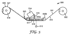
図5を参照すると、本開示の例示的な方法で使用するための装置500の概略図が提供されている。装置は、少なくとも2つのローラ552及び518(これらのうちの少なくとも1つは、化学線透過性基材510を搬送するように構成されている)と、化学線を化学線透過性基材510を通して所定の線量で所定の位置に向けるように構成された、照射源512と、を含む。装置500は更に、化学線透過性基材510の主表面511上に組成物516を付着させる手段514と、化学線透過性基材510又は照射源512を互いに相対的な関係で搬送する手段518と、を含む。付着させる手段514は、基材510の主表面511上に組成物516をたまりとして分注するように構成された容器を備える。化学線透過性基材510は、装置の構成要素であるのとは対照的に、装置とは別個に得られる消耗材であることが多い。任意選択的に、装置500には、1つ以上の接着剤517及び519が形成されている基材510から未重合組成物516を除去するように構成された、エアナイフ520が備えられている。
With reference to FIG. 5, a schematic view of the
特定の実施形態では、使用時、図5に示す装置は以下のように動作する。化学線透過性基材510を搬送する手段518は、複数のローラ550を通して、化学線透過性基材510のウェブを駆動し、複数のローラ550は、組成物516をこれが接触する基材510の主表面511上に付着させる手段514によって供給される組成物516を保持するための収容領域を形成する。この実施形態における付着させる手段514は、化学線透過性基材510の上方に配設された容器である。照射源512は、放射線を、化学線透過性基材510を通して、1つ又は複数の所定の線量で1つ以上の所定の位置に向ける。照射された組成物516は少なくとも部分的に重合し、図5に示す接着剤517及び接着剤519のような少なくとも1つの接着剤を形成する。例えば、接着剤517は、照射源512が提供する特定の照射の結果、接着剤519と比べて幅に変化がある。基材510が巻き出しローラ552から、搬送する手段518(例えば、図5に示すような巻き取りローラ)へと駆動され続けるとき、エアナイフ520が基材510の主表面511に向けて空気を導いて、基材510の主表面511上に残存する、重合して接着剤を形成しなかった組成物516の除去を助ける。余分な組成物516は、複数のローラ550によって画定される収容領域に戻されることが好ましい。形成された接着剤(例えば、接着剤527及び接着剤529)が巻き取りローラ518に到達すると、化学線透過性基材510のウェブが巻き取られる。
In a particular embodiment, in use, the device shown in FIG. 5 operates as follows. The means 518 for transporting the chemical ray
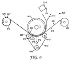
図6を参照すると、本開示の例示的な方法で使用するための装置600の概略図が提供されている。装置は、少なくとも2つのローラ652及び618(これらのうちの少なくとも1つは、化学線透過性基材610を搬送するように構成されている)と、化学線を化学線透過性基材610を通して所定の線量で所定の位置に向けるように構成された、照射源612と、を含む。装置600は更に、化学線透過性基材610の主表面611上に組成物616を付着させる手段614と、化学線透過性基材610又は照射源612を互いに相対的な関係で搬送する手段618と、を含む。化学線透過性基材610は、装置の構成要素であるのとは対照的に、装置とは別個に得られる消耗材であることが多い。付着させる手段614は、基材611の主表面611上に漏斗615を通して組成物616をたまりとして分注するように構成された容器を備える。装置は更に、化学線透過性基材610に接触し、化学線透過性基材610上に配設された組成物616のたまりのための空間を提供するための収容領域を縁部間に画定するように構成された、間隔を空けた1対の縁部(図示せず)を備える、ダムローラ645を含む。
With reference to FIG. 6, a schematic diagram of the
化学線透過性基材610にダムローラ645を接触させて、化学線透過性基材610からの組成物616の漏れを最小限にするのを助けるための更なる手段を設けてもよい。図6に示す装置では、そのような手段は、3つのプレスローラ646、647、及び648と、ベルト649と、を含み、この場合、2つのプレスローラ646、647がダムローラ645に隣接して配設されており、第3のプレスローラ648が最初の2つのプレスローラ646、647から距離をおいて配設されている。ベルト649は、3つのプレスローラ646、647、及び648の周囲にループ状に構成され、化学線透過性基材610に接触して配設されている。3つのプレスローラ646、647、及び648は、ベルトに力を加えてこれを化学線透過性基材610に接触させた状態に維持するように構成されている。化学線透過性基材610が搬送される際、ベルト649は3つのプレスローラ646、647、及び648の周囲を通過する。
Additional means may be provided to bring the
使用時には、装置600は上記した図5の装置500と同様に動作し、これには、基材610が巻き出しローラ652から(並びにダムローラ645の下方を通って)、搬送する手段618(例えば、図6に示すような巻き取りローラ)へと駆動され続けるとき、エアナイフ620が基材610の主表面611に向けて空気を導いて、基材610の主表面611上に残存する、化学線照射源612からの照射により重合して接着剤を形成しなかった組成物616の除去を助けることが含まれる。余分な組成物616は、ダムローラ645によって画定される収容領域に戻されることが好ましい。形成された接着剤(例えば、接着剤627及び接着剤629)が巻き取りローラ618に到達すると、化学線透過性基材610のウェブが巻き取られる。
In use, the
図7を参照すると、本開示の例示的な方法で使用するための装置700の概略図が提供されている。装置は、化学線透過性基材710を搬送するように構成された、少なくとも2つのローラ752及び718(これらのうちの少なくとも1つは、化学線透過性基材710を搬送するように構成されている)と、化学線を化学線透過性基材710を通して所定の線量で所定の位置に向けるように構成された、照射源712と、を含む。装置700は更に、化学線透過性基材710の主表面711上に組成物716を付着させる手段714と、化学線透過性基材710又は照射源712を互いに相対的な関係で搬送する手段718と、を含む。化学線透過性基材710は、装置の構成要素であるのとは対照的に、装置700とは別個に得られる消耗材であることが多い。装置は更に、化学線透過性基材710に接触し、化学線透過性基材710上に配設された組成物716のたまりのための空間を提供するための収容領域を縁部間に画定するように構成された、間隔を空けた1対の縁部(図示せず)を備える、ダムローラ745を含む。付着させる手段714は、ダムローラ745の表面上に組成物716を薄層として分注するように構成された容器を備え、この薄層は、ダムローラ745の周囲を走行し基材710の主表面711上にたまりを形成する。
With reference to FIG. 7, a schematic diagram of the
化学線透過性基材710にダムローラ745を接触させて、化学線透過性基材710からの組成物716の漏れを最小限にするのを助けるための更なる手段を設けてもよい。図7に示す装置では、そのような手段は2つのテンションローラ754及び756を含み、この場合、化学線透過性基材710は、一方のテンションローラ756の上、ダムローラ745の下、及び他方のテンションローラ754の上に送り込まれる。この構成により、テンションローラ754及び756を、化学線透過性基材710が装置を通して搬送される際に化学線透過性基材710に力を加えて基材710をダムローラ745と接触した状態に維持するように構成することが可能になる。
Additional means may be provided to bring the
使用時には、装置700は上記した図5の装置500と同様に動作し、これには、基材710が巻き出しローラ752から(並びに第1のテンションローラ756の上、ダムローラ745の下、及び第2のテンションローラ754の上を通って)、搬送する手段718(例えば、図7に示すような巻き取りローラ)へと駆動され続けるとき、エアナイフ720が基材710の主表面711に向けて空気を導いて、基材710の主表面711上に残存する、化学線照射源712からの照射により重合して接着剤を形成しなかった組成物716の除去を助けることが含まれる。余分な組成物716は、ダムローラ745によって画定される収容領域に戻されることが好ましい。形成された接着剤(例えば、接着剤727及び接着剤729)が巻き取りローラ718に到達すると、化学線透過性基材710のウェブが巻き取られる。
In use, the
図8を参照すると、本開示の例示的な方法で使用するための装置800の概略図が提供されている。装置は、化学線透過性基材810を搬送するように構成された、少なくとも2つのローラ852及び818(これらのうちの少なくとも1つは、化学線透過性基材810を搬送するように構成されている)と、化学線を化学線透過性基材810を通して所定の線量で所定の位置に向けるように構成された、照射源812と、を含む。装置800は更に、化学線透過性基材810の主表面811上に組成物816を付着させる手段814と、化学線透過性基材810又は照射源812を互いに相対的な関係で搬送する手段818と、を含む。化学線透過性基材810は、装置の構成要素であるのとは対照的に、装置800とは別個に得られる消耗材であることが多い。装置は更に、化学線透過性基材810に接触し、化学線透過性基材810上に配設された組成物816のたまりのための空間を提供するための収容領域を縁部間に画定するように構成された、間隔を空けた1対の縁部(図示せず)を備える、ダムローラ845を含む。付着させる手段814は、ダムローラ845の表面上に組成物816を薄層として分注するように構成された容器を備え、この薄層は、ダムローラ845の周囲を走行し基材810の主表面811上にたまりを形成する。
With reference to FIG. 8, a schematic view of the
化学線透過性基材810にダムローラ845を接触させて、化学線透過性基材810からの組成物816の漏れを最小限にするのを助けるための更なる手段を設けてもよい。図8に示す装置では、そのような手段は2つのテンションローラ854及び856を含み、この場合、化学線透過性基材810は、一方のテンションローラ856の上、ダムローラ845の下、及び他方のテンションローラ854の上に送り込まれる。この構成により、テンションローラ854及び856を、化学線透過性基材810が装置を通して搬送される際に化学線透過性基材810に力を加えて基材810をダムローラ845と接触した状態に維持するように構成することが可能になる。図8に示す装置では、テンションローラは、化学線透過性基材810がダムローラ845の円周の50パーセント超と接触するようにダムローラ845に隣接して配設されて、化学線透過性基材810からの組成物816の漏れを最小限にするのを更に助ける。
Additional means may be provided to bring the
使用時には、装置800は図5の装置500と同様に動作し、これには、基材810が巻き出しローラ852から(並びに第1のテンションローラ856の上、ダムローラ845の下、及び第2のテンションローラ854の上を通って)、搬送する手段818(例えば、図8に示すような巻き取りローラ)へと駆動され続けることが含まれる。更に、特定の実施形態では、形成された接着剤(例えば827、829)は1つ以上の第2の照射源832によって照射されて、基材810の巻き取り前に接着剤を事後硬化する。エアナイフ820は任意選択的に、基材811の主表面810に向かって空気を導いて、化学線照射源812からの照射により重合して接着剤を形成しなかった、基材810の主表面811上に残存している組成物816の除去を助ける。余分な組成物816は、ダムローラ845によって画定される収容領域に戻されることが好ましい。形成された接着剤(例えば、接着剤827及び接着剤829)が巻き取りローラ818に到達すると、化学線透過性基材810のウェブが巻き取られる。
In use, the
図9を参照すると、本開示の例示的な方法で使用するための装置900の概略図が提供されている。装置は、少なくとも2つのローラ952及び918(これらのうちの少なくとも1つは、化学線透過性基材910を搬送するように構成されている)と、化学線を化学線透過性基材910を通して所定の線量で所定の位置に向けるように構成された、照射源912と、を含む。装置900は更に、化学線透過性基材910の主表面911上に組成物916を付着させる手段914と、化学線透過性基材910又は照射源912を互いに相対的な関係で搬送する手段918と、を含む。付着させる手段914は、基材910の主表面911上に組成物916を分注するように構成されたダイを備える。このような実施形態では、組成物916は、基材910の側縁から漏れ出ることなく基材910の主表面911上に残留するのに十分な粘性を有することが好ましい。化学線透過性基材910は、装置の構成要素であるのとは対照的に、装置900とは別個に得られる消耗材であることが多い。任意選択的に、装置900には、1つ以上の接着剤917及び919が形成されている基材910から未重合組成物916を除去するように構成された、エアナイフ920が備えられている。
With reference to FIG. 9, a schematic view of the apparatus 900 for use in the exemplary method of the present disclosure is provided. The apparatus comprises at least two
装置900の更なる任意選択的な構成要素は、1つ以上の接着剤(例えば927及び/又は929)が表面に配設された基材910の部分をスライスする、ブレード960である。図9に示す実施形態では、1つ以上の形成された接着剤を含む基材910の切片の山961が示されている。代替の実施形態では、1つ以上の接着剤(例えば927及び/又は929)が表面に形成された基材910は、巻き取りロール(図示せず)上に巻き取られる。
A further optional component of the device 900 is a
特定の実施形態では、使用時、図9に示す装置は以下のように動作する。ダイ914は、化学線透過性基材910の主表面911上に組成物916を付着させる。照射源912は、化学線透過性基材910を通して、放射線を、1つ又は複数の所定の線量で1つ以上の所定の位置に向ける。照射された組成物916は少なくとも部分的に重合し、図9に示す接着剤917及び接着剤919のような少なくとも1つの接着剤を形成する。例えば、接着剤917は、照射源912が提供する特定の照射の結果、接着剤919と比べて幅に変化がある。化学線透過性基材910を搬送する手段918は、化学線透過性基材910のウェブをローラ952上に駆動して、重合して接着剤(例えば、917及び919)を形成しなかった組成物916が重力により分離し始めることを可能にする。基材910が第1のローラ918から第2のローラ952へと駆動され続けるとき、エアナイフ920が基材910の主表面911に向けて空気を導いて、基材910の主表面911上に残存している組成物916の除去を助ける。余分な組成物916は、リサイクル又はリユースのために容器958内に入れられるのが好ましい。少なくとも1つの形成された接着剤(例えば接着剤927及び/又は接着剤929)を保持する基材910の特定の部分がブレード960に達すると、ブレード960が使用され、化学線透過性基材910のその部分が切り離される(及び、少なくとも1つの形成された接着剤927を各々含む基材910の切片の山961に、任意選択的に追加される。
In a particular embodiment, in use, the device shown in FIG. 9 operates as follows. The
図1〜図9をそれぞれ参照すると、化学線透過性基材は、ガラス(例えば図1〜図4のいずれかの場合)、又はポリマー材料(例えば図1〜図9のいずれかの場合)を含む。化学線透過性基材がポリマー材料を含む場合、基材は通常、ポリエチレンテレフタレート、ポリエチレンナフタレート、ポリカーボネート、ポリイミド、シクロオレフィンフィルム、ポリ(メチルメタクリレート)、又はこれらの組合せから選択されるポリマー材料を含む。化学線透過性基材がガラスを含む場合、基材は通常、ホウケイ酸ナトリウムガラス、ソーダ石灰ガラス、及び石英ガラスから選択されるガラスを含む。一部の実施形態では、基材は、多層構造、例えば、ポリマーシート、接着層、及びライナーを含む。接着剤が多層構造から別の表面又は基材に移されることを意図した実施形態では、多層構造は、一体型接着剤が表面に配設されるコーティング(例えば剥離コーティング)を含む。 With reference to FIGS. 1 to 9, the chemical ray-permeable substrate is made of glass (for example, in any of FIGS. 1 to 4) or polymer material (for example, in any of FIGS. 1 to 9). include. When the chemical ray permeable substrate contains a polymeric material, the substrate is usually a polymeric material selected from polyethylene terephthalate, polyethylene naphthalate, polycarbonate, polyimide, cycloolefin film, poly (methylmethacrylate), or a combination thereof. include. When the chemical ray permeable substrate comprises glass, the substrate usually comprises a glass selected from sodium borosilicate glass, soda-lime glass, and quartz glass. In some embodiments, the substrate comprises a multi-layer structure, such as a polymer sheet, an adhesive layer, and a liner. In embodiments where the adhesive is intended to be transferred from the multi-layer structure to another surface or substrate, the multi-layer structure includes a coating (eg, a release coating) in which an integral adhesive is disposed on the surface.
図1〜図9の各々は、化学線透過性基材又は照射源を互い対して相対的な関係で搬送する手段を指していた。搬送する手段としては一般に、製造技術において知られているような機械的手段、例えば、モータ、サーボモータ、ステッパモータ、又はこれらの任意の組合わせが挙げられる。多くの場合、モータは最終的に、基材(例えば、円柱又は不定長のウェブ)及び/又は照射源を搬送する1つ以上のローラを駆動する。 Each of FIGS. 1 to 9 refers to a means for transporting a chemical ray-permeable substrate or an irradiation source in a relative relationship with each other. Means of transport generally include mechanical means as known in manufacturing technology, such as motors, servomotors, stepper motors, or any combination thereof. In many cases, the motor ultimately drives one or more rollers that carry a substrate (eg, a cylinder or a web of indefinite length) and / or an irradiation source.
図1〜図9をそれぞれ参照すると、化学線は通常、発光ダイオード(LED)を備えたデジタル光プロジェクタ(DLP)、ランプを備えたDLP、レーザを備えたレーザ走査デバイス、バックライトを備えた液晶ディスプレイ(LCD)パネル、ランプを備えたフォトマスク、又はLEDを備えたフォトマスクである、照射源によって提供される。より具体的には、図10にはLED又はランプを備えたDLPの概略図が提供されており、図11a及び図11bにはランプ又はLEDを備えたフォトマスクの概略図が提供されており、図12にはバックライトを備えたLCDパネルの概略図が提供されており、図13にはレーザを備えたレーザ走査デバイスの概略図が提供されている。 With reference to FIGS. 1-9, respectively, chemical rays are typically a digital light projector (DLP) with light emitting diodes (LEDs), a DLP with a lamp, a laser scanning device with a laser, and a liquid crystal display with a backlight. Provided by an irradiation source, which is a liquid crystal display (LCD) panel, a photomask with a lamp, or a photomask with an LED. More specifically, FIG. 10 provides a schematic diagram of a DLP with an LED or a lamp, and FIGS. 11a and 11b provide a schematic diagram of a photomask with a lamp or an LED. FIG. 12 provides a schematic of a backlit LCD panel, and FIG. 13 provides a schematic of a laser scanning device with a laser.
ここで図10を参照すると、LED又はランプ1066(1066はLED又はランプのいずれかを表す)を備えたDLP1065を備える、本開示の例示的な方法で使用するための照射源1000の概略図が提供されている。DLP1065は、複数の個別に動かせる反射体、例えば第1の反射体1062、第2の反射体1063、及び第3の反射体1064を含む。各反射体は、LED又はランプ1066からの照射を、化学線透過性基材1010の主表面1011上に配設された組成物1016の所定の位置へと向けるような、特定の角度で配置されている。使用時には、LED又はランプ1066からの照射の強度及び継続時間は、1つ以上の接着剤1017及び1019を形成する際に、基材1010の主表面1011に垂直な方向における組成物1016の硬化(例えば重合)の深さに影響を与えることになる。例えば、一体型接着剤1017のある部分1017bは、同じ一体型接着剤1017の別の部分1017aよりも大きい厚みを有する。このことは、部分1017bを、部分1017aが照射されるよりも高い線量で照射することによって達成され得る。一方、接着剤1019は、その幅にわたって同じ線量を受けるため、その幅にわたって単一の厚みを有する。DLPを採用する利点は、個々の反射体を(例えば、コンピュータ制御を用いて)容易に調節可能であり、このため設備の大きな改変を要することなく必要に応じて照射位置及び線量が変えられ、これにより結果的に形成される接着剤の形状が変えられることである。DLPは当技術分野で周知であり、限定するものではないが例えば、米国特許第5,658,063号(Nasserbakht)、同第5,905,545号(Poradishら)、同第6,587,159号(Dewald)、同第7,164,397号(Pettittら)、同第7,360,905号(Davisら)、同第8,705,133号(Liebら)、及び同第8,820,944号(Vasquez)に記載されている装置である。好適なDLPが、例えばTexas Instruments(Dallas,TX)から市販されている。上で示されたように、DLPと共に、LEDか又はランプのいずれかを採用してもよい。好適なランプとしては、フラッシュランプ、低圧水銀ランプ、中圧水銀ランプ、及び/又はマイクロ波駆動ランプを挙げることができる。当業者は、特定の重合性組成物の重合を開始するのに必要な化学線を提供するために好適なLED又はランプ光源、例えばLuminus Inc.(Sunnyvale,CA)から入手可能なUV LED CBT−39−UVを選択することができる。
Referring now to FIG. 10, a schematic representation of an
ここで図11a及び図11bを参照すると、本開示の例示的な方法で使用するための、LED又はランプ1166(1166はLED又はランプのいずれかを表す)を備えた少なくとも1つのフォトマスク1170a及び1170bを備える照射源1100を含む概略図が提供されている。1つ又は複数のフォトマスク1170a及び1170bの少なくとも一部にわたって照射を拡散させるために、LED又はランプ1166と共に、凸面1168を有するレンズ1167が使用される。図11aに示すように、第1のフォトマスク1170aを使用して、LED又はランプ1166からの照射を、化学線透過性基材1110の主表面1111上に配設された組成物1116の所定の位置へと向ける。使用時には、LED又はランプ1166からの照射の強度及び継続時間は、1つ以上の接着剤1117及び1119を形成する際に、基材1110の主表面1111に垂直な方向における組成物1116の硬化(例えば重合)の深さに影響を与えることになる。例えば、一体型接着剤1117のある部分1117bは、同じ一体型接着剤1117の別の部分1017aよりも大きい厚みを有する。このことは、2つ以上のフォトマスクを使用することによって達成され得る。例えば、図11aを参照すると、複数の部分1171aが設けられているフォトマスク1170aが示されており、この部分を通して、組成物1116を硬化させるように照射を方向付けることができる。ここで図11bを参照すると、1つの部分1171bが設けられている第2のフォトマスク1170bが示されており、この部分を通して、組成物1116を更に硬化させるように照射を方向付けることができる。図示した実施形態では、部分1117bは部分1117aよりも大きな厚みを有するが、その理由は、照射が2回、すなわち第1のフォトマスク1170aを使用して1回、第2のフォトマスク1170bを使用して1回行われ、この結果、部分1117bの照射が部分1117aよりも高い線量を有するからである。一方、接着剤1119は、第1のフォトマスク1170aのみを通した照射への曝露により、その幅にわたって同じ線量を受けるため、その幅にわたって単一の厚みを有する。図11a及び図11bのフォトマスクは不透明な部分及び透明な部分を有するものとして示されているが、当業者は、階調を含むフォトマスクを使用して、組成物の異なる位置での硬化の勾配を実現できることを諒解するであろう。好適なフォトマスクが市販されており、例えば、Infinite Graphics(Minneapolis,MN)によるNanoSculpt Photomasksがある。DLPの使用と同様に、フォトマスクと共に、LED又はランプのいずれかを採用してもよい。
With reference to FIGS. 11a and 11b, at least one
図12を参照すると、本開示の例示的な方法で使用するための、デジタルフォトマスク1272(例えば、バックライト1266を備えたLCD)を備える照射源1200の概略図が提供されており、バックライトはLED又はランプ1266(1266はLED又はランプのいずれかを表す)を備える。デジタルフォトマスク1272の少なくとも一部にわたって照射を拡散させるために、バックライト1266と共に、凸面1268を有するレンズ1267が使用される。使用時には、バックライト1266からの照射の強度及び継続時間は、1つ以上の接着剤1217及び1219を形成する際に、基材1210の主表面1211に垂直な方向における組成物1216の硬化(例えば重合)の深さに影響を与えることになる。例えば、一体型接着剤1217のある部分1217bは、同じ一体型接着剤1217の別の部分1217aよりも大きい厚みを有する。このことは、部分1217bを、部分1217aが照射されるよりも高い線量で照射することによって達成され得る。一方、接着剤1219は、その幅にわたって同じ線量を受けるため、その幅にわたって単一の厚みを有する。デジタルフォトマスクを採用する利点は、個々のピクセルを(例えば、コンピュータ制御を用いて)容易に調節可能であり、このため設備の大きな改変を要することなく必要に応じて照射位置及び線量が変えられ、これにより結果的に形成される接着剤の形状が変えられることである。好適なLCDが市販されており、例えば、シャープ株式会社(大阪、日本)から入手可能なLCD LQ043T1DG28がある。
Referring to FIG. 12, a schematic of an
図13を参照すると、本開示の例示的な方法で使用するための、レーザ1366を備えたレーザ走査デバイス1362を備える照射源1300の概略図が提供されている。レーザ走査デバイス1362は、少なくとも1つの個別に動かせるミラーを含む。各ミラーは、レーザ1366からの照射を、化学線透過性基材1310の主表面1311上に配設された組成物1316の所定の位置へと向けるような、特定の角度で配置されている。使用時には、レーザ1366からの照射の強度及び継続時間は、1つ以上の接着剤1317及び1319を形成する際に、基材1310の主表面1311に垂直な方向における組成物1316の硬化(例えば重合)の深さに影響を与えることになる。例えば、一体型接着剤1317のある部分1317bは、同じ一体型接着剤1317の別の部分1317aよりも大きい厚みを有する。このことは、部分1317bを、部分1317aが照射されるよりも高い線量で照射することによって達成され得る。一方、接着剤1319は、その幅にわたって同じ線量を受けるため、その幅にわたって単一の厚みを有する。レーザ走査デバイスを採用する利点は、個々のミラーを(例えば、コンピュータ制御を用いて)容易に調節可能であり、このため設備の大きな改変を要することなく必要に応じて照射位置及び線量が変えられ、これにより結果的に形成される接着剤の形状が変えられることである。好適なレーザ走査デバイスが市販されており、例えば、Sino−Galvo(Beijing)Technology Co.,LTD(北京、中国)によるJS2808 Galvanometer Scannerがある。当業者は、特定の重合性組成物の重合を開始するのに必要な化学線を提供するために好適なレーザ、例えばCoherent Inc.(Santa Clara,CA)によるCUBE 405−100C Diode Laser Systemを選択することができる。
With reference to FIG. 13, a schematic view of an
このように、本開示の上記の照射源はいずれも、本明細書で開示されている実施形態の装置の各々で使用するのに適している。1つ以上の所定の位置において1つ以上の所定の照射の線量を提供するように容易に構成されて、サイズ及び形状、特に基材に垂直な厚みに変化のある接着剤の製造が可能になることが、これらの照射源の利点である。 As such, all of the above sources of irradiation of the present disclosure are suitable for use in each of the devices of the embodiments disclosed herein. Easily configured to provide a dose of one or more predetermined doses at one or more predetermined locations, allowing the production of adhesives that vary in size and shape, especially in thickness perpendicular to the substrate. It is an advantage of these irradiation sources.
例示的な実施形態 Illustrative Embodiment
実施形態1は、接着剤の製造方法である。この方法は、化学線透過性基材の主表面上に配設された化学線重合性接着剤前駆体組成物を得ることと、化学線重合性接着剤前駆体組成物の第1の部分を化学線透過性基材を通して第1の照射線量で照射して、第1の接着剤を形成することと、を含む。この方法は更に、化学線透過性基材を移動させることと、化学線重合性接着剤前駆体組成物の第2の部分を化学線透過性基材を通して第2の照射線量で照射して、第2の接着剤を形成することと、を含む。 The first embodiment is a method for producing an adhesive. This method obtains a chemical ray-polymerizable adhesive precursor composition disposed on the main surface of a chemical ray-permeable substrate and a first portion of the chemical ray-polymerizable adhesive precursor composition. It comprises irradiating with a first irradiation dose through a chemical ray permeable substrate to form a first adhesive. This method further involves moving the chemical ray permeable substrate and irradiating a second portion of the chemical ray polymerizable adhesive precursor composition through the chemical ray permeable substrate with a second irradiation dose. Includes forming a second adhesive.
実施形態2は、基材を移動させる前に、化学線重合性接着剤前駆体組成物の第3の部分を化学線透過性基材を通して照射して、第3の接着剤を形成することを更に含む、実施形態1に記載の方法である。 In the second embodiment, the third portion of the chemical ray-polymerizable adhesive precursor composition is irradiated through the chemical ray-permeable base material to form the third adhesive before moving the base material. The method according to the first embodiment, further comprising.
実施形態3は、第1の部分と第3の部分は互いと隣接しているか又は重なり合っている、実施形態1又は実施形態2に記載の方法である。 The third embodiment is the method according to the first or second embodiment, wherein the first portion and the third portion are adjacent to or overlap each other.
実施形態4は、第1の照射線量と第3の照射線量は同じではなく、これにより、第1の接着剤及び第3の接着剤を含む一体型接着剤であって、化学線透過性基材に垂直な軸線において厚みが変化する一体型接着剤が形成される、実施形態1〜3のいずれかに記載の方法である。
In the fourth embodiment, the first irradiation dose and the third irradiation dose are not the same, whereby the one-piece adhesive containing the first adhesive and the third adhesive is a chemical ray-permeable group. The method according to any one of
実施形態5は、第1の接着剤を事後硬化させることを更に含む、実施形態1〜4のいずれかに記載の方法である。
The fifth embodiment is the method according to any one of
実施形態6は、事後硬化は化学線又は熱を用いることを含む、実施形態5に記載の方法である。 The sixth embodiment is the method according to the fifth embodiment, which comprises using chemical rays or heat for post-curing.
実施形態7は、化学線重合性接着剤前駆体組成物の第4の部分を化学線透過性基材を通して照射して、第4の接着剤を形成することを更に含む、実施形態1〜6のいずれかに記載の方法である。 Embodiment 7 further comprises irradiating a fourth portion of the chemical ray-polymerizable adhesive precursor composition through a chemical ray-permeable substrate to form a fourth adhesive, embodiments 1-6. It is the method described in any of.
実施形態8は、第2の部分と第4の部分が互いと隣接しているか又は重なり合っており、これにより、第2の接着剤及び第4の接着剤を含む第2の一体型接着剤であって、化学線透過性基材の主表面に垂直な軸線において厚みが変化する第2の一体型接着剤が形成される、実施形態7に記載の方法である。 In the eighth embodiment, the second part and the fourth part are adjacent to each other or overlap with each other, whereby the second adhesive and the second integrated adhesive containing the fourth adhesive are used. The method according to the seventh embodiment, wherein a second integrated adhesive whose thickness changes along an axis perpendicular to the main surface of the chemical ray permeable base material is formed.
実施形態9は、気体、真空、流体、又はこれらの組合せを用いて、第1の接着剤から照射後に接着剤と接触して残存している化学線重合性接着剤前駆体組成物を除去することを更に含む、実施形態1〜8のいずれかに記載の方法である。
In the ninth embodiment, a gas, a vacuum, a fluid, or a combination thereof is used to remove the remaining chemical ray-polymerizable adhesive precursor composition from the first adhesive in contact with the adhesive after irradiation. The method according to any one of
実施形態10は、第1の接着剤を基材から除去することを更に含む、実施形態1〜9のいずれかに記載の方法である。
実施形態11は、第1の接着剤は第2の基材と一緒に除去される、実施形態10に記載の方法である。 The eleventh embodiment is the method according to the tenth embodiment, wherein the first adhesive is removed together with the second base material.
実施形態12は、第2の基材は構造化シートを備える、実施形態11に記載の方法である。 The twelfth embodiment is the method according to the eleventh embodiment, wherein the second base material includes a structured sheet.
実施形態13は、ロボットを用いて第1の一体型接着剤を基材から除去することを含む、実施形態10に記載の方法である。 13th embodiment is the method according to 10th embodiment, which comprises removing the first integrated adhesive from the substrate using a robot.
実施形態14は、基材をクリーニングすることを更に含む、実施形態10〜13のいずれかに記載の方法である。
実施形態15は、基材は剥離材料でコーティングされている、実施形態1〜14のいずれかに記載の方法である。 Embodiment 15 is the method according to any of embodiments 1-14, wherein the substrate is coated with a release material.
実施形態16は、基材はガラス又はポリマー材料を含む、実施形態1〜15のいずれかに記載の方法である。
実施形態17は、基材は円柱の形態である、実施形態1〜16のいずれかに記載の方法である。
実施形態18は、化学線重合性接着剤前駆体組成物を保持した容器を通して円柱を回転させて、化学線重合性接着剤前駆体組成物を基材上に配設することを含む、実施形態17に記載の方法である。
実施形態19は、前駆体組成物は基材の主表面上にたまりとして配設される、実施形態1〜16のいずれかに記載の方法である。 19th embodiment is the method according to any of embodiments 1-16, wherein the precursor composition is disposed as a puddle on the main surface of the substrate.
実施形態20は、第1の線量の照射時間は第2の線量の照射時間よりも短い、実施形態1〜19のいずれかに記載の方法である。
The 20th embodiment is the method according to any one of
実施形態21は、第1の線量の化学線強度は第2の線量の化学線強度よりも低い、実施形態1〜20のいずれかに記載の方法である。 21 is the method according to any of embodiments 1-20, wherein the first dose of chemical line intensity is lower than the second dose of chemical line intensity.
実施形態22は、第1の部分を照射することは第2の部分を照射する前に行われる、実施形態1〜21のいずれかに記載の方法である。 22 is the method according to any of embodiments 1-21, wherein irradiating the first portion is performed before irradiating the second portion.
実施形態23は、第1の部分を照射することは第2の部分を照射することと同時に行われる、実施形態1〜22のいずれかに記載の方法である。
23 is the method according to any one of
実施形態24は、第1の接着剤は、感圧性接着剤(PSA)、構造接着剤、構造ハイブリッド接着剤、ホットメルト接着剤、又はこれらの組合せである、実施形態1〜23のいずれかに記載の方法である。
In the 24th embodiment, the first adhesive is any of
実施形態25は、化学線重合性接着剤前駆体組成物は、アクリレート、2部アクリレート及びエポキシ系、2部アクリレート及びウレタン系、又はこれらの組合せを含む、実施形態1〜24のいずれかに記載の方法である。
25. The 25th embodiment is described in any one of
実施形態26は、化学線重合性接着剤前駆体組成物はアクリレートを含む、実施形態1〜25のいずれかに記載の方法である。
The 26th embodiment is the method according to any one of
実施形態27は、光開始剤は、1−ヒドロキシシクロヘキシルフェニルケトン、2,2−ジメトキシ−1,2−ジフェニルエタン−1−オン、ビス(2,4,6−トリメチルベンゾイル)フェニルホスフィンオキシド、1−[4−(2−ヒドロキシエトキシ)フェニル]−2−ヒドロキシ−2−メチル−1−プロパン−1−オン、2−ベンジル−2−ジメチルアミノ−1−(4−モルホリノフェニル)ブタノン、2−メチル−1−[4−(メチルチオ)フェニル]−2−モルホリノプロパン−1−オン、及び2−ヒドロキシ−2−メチル−1−フェニルプロパン−1−オンから選択される、実施形態1〜26のいずれかに記載の方法である。 In the 27th embodiment, the photoinitiator is 1-hydroxycyclohexylphenylketone, 2,2-dimethoxy-1,2-diphenylethane-1-one, bis (2,4,6-trimethylbenzoyl) phenylphosphine oxide, 1 -[4- (2-Hydroxyethoxy) phenyl] -2-hydroxy-2-methyl-1-propane-1-one, 2-benzyl-2-dimethylamino-1- (4-morpholinophenyl) butanone, 2- Of Embodiments 1-26, selected from methyl-1- [4- (methylthio) phenyl] -2-morpholinopropane-1-one and 2-hydroxy-2-methyl-1-phenylpropane-1-one. It is the method described in either.
実施形態28は、化学線は、発光ダイオード(LED)を備えたデジタル光プロジェクタ(DLP)、ランプを備えたDLP、レーザを備えたレーザ走査デバイス、バックライトを備えた液晶ディスプレイ(LCD)パネル、ランプを備えたフォトマスク、又はLEDを備えたフォトマスクによって提供される、実施形態1〜27のいずれかに記載の方法である。 In embodiment 28, the chemical rays are a digital light projector (DLP) with light emitting diodes (LEDs), a DLP with a lamp, a laser scanning device with a laser, a liquid crystal display (LCD) panel with a backlight, and so on. The method according to any of embodiments 1-27, provided by a photomask with a lamp or a photomask with an LED.
実施形態29は、ランプは、フラッシュランプ、低圧水銀ランプ、中圧水銀ランプ、及び/又はマイクロ波駆動ランプから選択される、実施形態28に記載の方法である。 29 is the method of embodiment 28, wherein the lamp is selected from flash lamps, low pressure mercury lamps, medium pressure mercury lamps, and / or microwave driven lamps.
実施形態30は、第1の接着剤は2つの材料を1つに接着する、実施形態1〜29のいずれかに記載の方法である。 30 is the method according to any of embodiments 1-29, wherein the first adhesive adheres two materials together.
実施形態31は、第1の接着剤は様々な屈折率を有する、実施形態1〜30のいずれかに記載の方法である。
The 31st embodiment is the method according to any one of
実施形態32は、基材は多層構造を含む、実施形態1〜31のいずれかに記載の方法である。 Embodiment 32 is the method according to any one of embodiments 1-31, wherein the substrate comprises a multilayer structure.
実施形態33は、多層構造は、ポリマーシート、接着層、及びライナーを含む、実施形態32に記載の方法である。 The 33rd embodiment is the method according to the 32nd embodiment, wherein the multilayer structure includes a polymer sheet, an adhesive layer, and a liner.
実施形態34は、多層構造は、第1の接着剤が表面に配設されるコーティングを含む、実施形態32又は実施形態33に記載の方法である。 Embodiment 34 is the method of embodiment 32 or 33, wherein the multilayer structure comprises a coating in which a first adhesive is disposed on the surface.
実施形態35は、化学線重合性接着剤前駆体組成物は100%重合性前駆体組成物である、実施形態1〜実施形態34のいずれかに記載の方法である。
The 35th embodiment is the method according to any one of
実施形態36は、化学線重合性接着剤前駆体組成物は少なくとも1種の溶媒を含む、実施形態1〜35のいずれかに記載の方法である。
The 36th embodiment is the method according to any one of
実施形態37は、剥離材料はシリコーンを含む、実施形態15に記載の方法である。 The 37th embodiment is the method according to the 15th embodiment, wherein the peeling material contains silicone.
実施形態38は、方法は、摂氏20度以上〜摂氏150度以下の温度で実施される、実施形態1〜37のいずれかに記載の方法である。 38 is the method according to any of embodiments 1-37, wherein the method is carried out at a temperature of 20 degrees Celsius or higher to 150 degrees Celsius or lower.
実施形態39は、接着剤の製造方法である。この方法は、化学線透過性基材の主表面上に配設された化学線重合性接着剤前駆体組成物を得ることと、化学線重合性接着剤前駆体組成物の第1の部分を化学線透過性基材を通して第1の照射線量で照射することと、を含む。この方法は更に、化学線重合性接着剤前駆体組成物の第2の部分を化学線透過性基材を通して第2の照射線量で照射することと、化学線透過性基材を移動させることと、を含む。第1の部分と第2の部分は互いと隣接しているか又は重なり合っており、第1の照射線量及び第2の照射線量は同じではなく、これにより、化学線透過性基材に垂直な軸線において厚みが変化する一体型接着剤が形成される。 Embodiment 39 is a method for producing an adhesive. This method obtains a chemical ray-polymerizable adhesive precursor composition disposed on the main surface of a chemical ray-permeable substrate and a first portion of the chemical ray-polymerizable adhesive precursor composition. Including irradiation with a first irradiation dose through a chemical ray permeable substrate. The method further comprises irradiating a second portion of the chemical ray-polymerizable adhesive precursor composition through the chemical ray permeable substrate with a second irradiation dose and moving the chemical ray permeable substrate. ,including. The first and second parts are adjacent to or overlap each other, and the first and second doses are not the same, which is the axis perpendicular to the chemical ray permeable substrate. An integral adhesive with varying thickness is formed in.
実施形態40は、基材の移動後、化学線重合性接着剤前駆体組成物の第3の部分を化学線透過性基材を通して第3の照射線量で照射することを更に含む、実施形態39に記載の方法である。 Embodiment 40 further comprises irradiating a third portion of the chemical ray-polymerizable adhesive precursor composition through the chemical ray-permeable substrate with a third irradiation dose after transfer of the substrate. It is the method described in.
実施形態41は、第1の照射線量と第3の照射線量は同じである、実施形態40に記載の方法である。 The 41st embodiment is the method according to the 40th embodiment, wherein the first irradiation dose and the third irradiation dose are the same.
実施形態42は、化学線重合性接着剤前駆体組成物の第4の部分を化学線透過性基材を通して第4の照射線量で照射することを更に含む、実施形態40又は実施形態41に記載の方法である。第3の部分と第4の部分は互いと隣接しているか又は重なり合っており、第3の照射線量及び第4の照射線量は同じではない。 42. Embodiment 42 is described in embodiment 40 or 41, further comprising irradiating a fourth portion of the chemical ray polymerizable adhesive precursor composition through a chemical ray permeable substrate with a fourth irradiation dose. This is the method. The third and fourth parts are adjacent to or overlap each other, and the third and fourth doses are not the same.
実施形態43は、化学線重合性接着剤前駆体組成物の第4の部分を化学線透過性基材を通して照射した後で、化学線透過性基材を移動させることを更に含む、実施形態42に記載の方法である。 Embodiment 43 further comprises moving a chemical ray permeable substrate after irradiating a fourth portion of the chemical ray polymerizable adhesive precursor composition through the chemical ray permeable substrate. It is the method described in.
実施形態44は、一体型接着剤を事後硬化させることを更に含む、実施形態39〜43のいずれかに記載の方法である。 Embodiment 44 is the method according to any of embodiments 39-43, further comprising post-curing the integral adhesive.
実施形態45は、事後硬化は化学線又は熱を用いることを含む、実施形態44に記載の方法である。 Embodiment 45 is the method of embodiment 44, wherein post-curing involves the use of chemical rays or heat.
実施形態46は、気体、真空、流体、又はこれらの組合せを用いて、照射後に一体型接着剤と接触して残存している状態から化学線重合性接着剤前駆体組成物を除去することを更に含む、実施形態39〜45のいずれかに記載の方法である。 The 46th embodiment uses a gas, vacuum, fluid, or a combination thereof to remove the chemical linearly polymerizable adhesive precursor composition from the remaining state in contact with the integrated adhesive after irradiation. The method according to any of embodiments 39-45, further comprising.
実施形態47は、一体型接着剤を基材から除去することを更に含む、実施形態39〜46のいずれかに記載の方法である。 Embodiment 47 is the method of any of embodiments 39-46, further comprising removing the integrated adhesive from the substrate.
実施形態48は、一体型接着剤は第2の基材と一緒に除去される、実施形態47に記載の方法である。 Embodiment 48 is the method of embodiment 47, wherein the integrated adhesive is removed together with the second substrate.
実施形態49は、第2の基材は構造化シートを含む、実施形態48に記載の方法である。 Embodiment 49 is the method of embodiment 48, wherein the second substrate comprises a structured sheet.
実施形態50は、ロボットを用いて一体型接着剤を基材から除去することを含む、実施形態47に記載の方法である。 The 50th embodiment is the method according to the 47th embodiment, which comprises removing the integrated adhesive from the substrate using a robot.
実施形態51は、基材をクリーニングすることを更に含む、実施形態47〜50のいずれかに記載の方法である。 Embodiment 51 is the method according to any of embodiments 47-50, further comprising cleaning the substrate.
実施形態52は、基材は剥離材料でコーティングされている、実施形態39〜51のいずれかに記載の方法である。 52 is the method according to any of embodiments 39-51, wherein the substrate is coated with a release material.
実施形態53は、基材はガラス又はポリマー材料を含む、実施形態39〜52のいずれかに記載の方法である。 Embodiment 53 is the method according to any of embodiments 39-52, wherein the substrate comprises a glass or polymeric material.
実施形態54は、基材は円柱の形態である、実施形態39〜53のいずれかに記載の方法である。 Embodiment 54 is the method according to any of embodiments 39-53, wherein the substrate is in the form of a cylinder.
実施形態55は、化学線重合性接着剤前駆体組成物を保持した容器を通して円柱を回転させて、化学線重合性接着剤前駆体組成物を基材上に配設することを含む、実施形態54に記載の方法である。 Embodiment 55 comprises rotating a column through a container holding the chemical ray-polymerizable adhesive precursor composition to dispose of the chemical ray-polymerizable adhesive precursor composition on a substrate. 54.
実施形態56は、前駆体組成物は基材の主表面上にたまりとして配設される、実施形態39〜53のいずれかに記載の方法である。 The 56th embodiment is the method according to any of embodiments 39-53, wherein the precursor composition is disposed as a puddle on the main surface of the substrate.
実施形態57は、第1の線量の照射時間は第2の線量の照射時間よりも短い、実施形態39〜56のいずれかに記載の方法である。 The 57th embodiment is the method according to any one of embodiments 39 to 56, wherein the irradiation time of the first dose is shorter than the irradiation time of the second dose.
実施形態58は、第1の線量の化学線強度は第2の線量の化学線強度よりも低い、実施形態39〜57のいずれかに記載の方法である。 The 58th embodiment is the method according to any one of embodiments 39-57, wherein the chemical ray intensity of the first dose is lower than the chemical ray intensity of the second dose.
実施形態59は、第1の部分を照射することは第2の部分を照射する前に行われる、実施形態39〜58のいずれかに記載の方法である。 Embodiment 59 is the method according to any of embodiments 39-58, wherein irradiating the first portion is performed before irradiating the second portion.
実施形態60は、第1の部分を照射することは第2の部分を照射することと同時に行われる、実施形態39〜59のいずれかに記載の方法である。 The 60th embodiment is the method according to any one of embodiments 39 to 59, wherein irradiating the first portion is performed at the same time as irradiating the second portion.
実施形態61は、一体型接着剤は、感圧性接着剤(PSA)、構造接着剤、構造ハイブリッド接着剤、ホットメルト接着剤、又はこれらの組合せである、実施形態39〜60のいずれかに記載の方法である。 In Embodiment 61, the integrated adhesive is any of Embodiments 39-60, wherein the integrated adhesive is a pressure sensitive adhesive (PSA), a structural adhesive, a structural hybrid adhesive, a hot melt adhesive, or a combination thereof. This is the method.
実施形態62は、化学線重合性接着剤前駆体組成物は、アクリレート、2部アクリレート及びエポキシ系、2部アクリレート及びウレタン系、又はこれらの組合せを含む、実施形態39〜61のいずれかに記載の方法である。 In the 62nd embodiment, the chemical ray-polymerizable adhesive precursor composition comprises any of acrylate, 2-part acrylate and epoxy-based, two-part acrylate and urethane-based, or a combination thereof. This is the method.
実施形態63は、化学線重合性接着剤前駆体組成物はアクリレートを含む、実施形態39〜62のいずれかに記載の方法である。 Embodiment 63 is the method according to any of embodiments 39-62, wherein the chemical line-polymerizable adhesive precursor composition comprises an acrylate.
実施形態64は、光開始剤は、1−ヒドロキシシクロヘキシルフェニルケトン、2,2−ジメトキシ−1,2−ジフェニルエタン−1−オン、ビス(2,4,6−トリメチルベンゾイル)フェニルホスフィンオキシド、1−[4−(2−ヒドロキシエトキシ)フェニル]−2−ヒドロキシ−2−メチル−1−プロパン−1−オン、2−ベンジル−2−ジメチルアミノ−1−(4−モルホリノフェニル)ブタノン、2−メチル−1−[4−(メチルチオ)フェニル]−2−モルホリノプロパン−1−オン、及び2−ヒドロキシ−2−メチル−1−フェニルプロパン−1−オンから選択される、実施形態39〜63のいずれかに記載の方法である。 In embodiment 64, the photoinitiator is 1-hydroxycyclohexylphenylketone, 2,2-dimethoxy-1,2-diphenylethane-1-one, bis (2,4,6-trimethylbenzoyl) phenylphosphine oxide, 1 -[4- (2-Hydroxyethoxy) phenyl] -2-hydroxy-2-methyl-1-propane-1-one, 2-benzyl-2-dimethylamino-1- (4-morpholinophenyl) butanone, 2- Of Embodiments 39-63, selected from methyl-1- [4- (methylthio) phenyl] -2-morpholinopropane-1-one and 2-hydroxy-2-methyl-1-phenylpropane-1-one. It is the method described in either.
実施形態65は、化学線は、発光ダイオード(LED)を備えたデジタル光プロジェクタ(DLP)、ランプを備えたDLP、レーザを備えたレーザ走査デバイス、バックライトを備えた液晶ディスプレイ(LCD)パネル、ランプを備えたフォトマスク、又はLEDを備えたフォトマスクによって提供される、実施形態39〜64のいずれかに記載の方法である。 In embodiment 65, the chemical rays are a digital light processing projector (DLP) with light emitting diodes (LEDs), a DLP with a lamp, a laser scanning device with a laser, a liquid crystal display (LCD) panel with a backlight, and so on. The method according to any of embodiments 39-64, provided by a photomask with a lamp or a photomask with an LED.
実施形態66は、ランプは、フラッシュランプ、低圧水銀ランプ、中圧水銀ランプ、及び/又はマイクロ波駆動ランプから選択される、実施形態65に記載の方法である。 Embodiment 66 is the method of embodiment 65, wherein the lamp is selected from flash lamps, low pressure mercury lamps, medium pressure mercury lamps, and / or microwave driven lamps.
実施形態67は、一体型接着剤は2つの材料を1つに接着する、実施形態39〜66のいずれかに記載の方法である。 Embodiment 67 is the method of any of embodiments 39-66, wherein the integrated adhesive adheres two materials together.
実施形態68は、一体型接着剤は様々な屈折率を有する、実施形態39〜67のいずれかに記載の方法である。 Embodiment 68 is the method according to any of embodiments 39-67, wherein the integrated adhesive has various refractive indexes.
実施形態69は、基材は多層構造を含む、実施形態39〜68のいずれかに記載の方法である。 Embodiment 69 is the method according to any of embodiments 39-68, wherein the substrate comprises a multilayer structure.
実施形態70は、多層構造は、ポリマーシート、接着層、及びライナーを含む、実施形態69に記載の方法である。 Embodiment 70 is the method of embodiment 69, wherein the multilayer structure comprises a polymer sheet, an adhesive layer, and a liner.
実施形態71は、多層構造は、一体型接着剤が表面に配設されるコーティングを含む、実施形態69又は実施形態70に記載の方法である。 Embodiment 71 is the method of embodiment 69 or 70, wherein the multilayer structure comprises a coating in which an integral adhesive is disposed on the surface.
実施形態72は、化学線重合性接着剤前駆体組成物は100%重合性前駆体組成物である、実施形態39〜実施形態71のいずれかに記載の方法である。 Embodiment 72 is the method according to any one of embodiments 39 to 71, wherein the chemical linearly polymerizable adhesive precursor composition is a 100% polymerizable precursor composition.
実施形態73は、化学線重合性接着剤前駆体組成物は少なくとも1種の溶媒を含む、実施形態39〜72のいずれかに記載の方法である。 Embodiment 73 is the method according to any of embodiments 39-72, wherein the chemical line-polymerizable adhesive precursor composition comprises at least one solvent.
実施形態74は、剥離材料はシリコーンを含む、実施形態73に記載の方法である。 Embodiment 74 is the method according to embodiment 73, wherein the release material comprises silicone.
実施形態75は、方法は、摂氏20度以上〜摂氏150度以下の温度で実施される、実施形態39〜74のいずれかに記載の方法である。 Embodiment 75 is the method according to any of embodiments 39-74, wherein the method is carried out at a temperature of 20 degrees Celsius or higher to 150 degrees Celsius or lower.
これらの実施例は単に例示を目的としたものであり、添付した特許請求の範囲を過度に限定することを意図しない。本開示の広い範囲を記載する数値範囲及びパラメータは、近似値であるが、特定の実施例に記載される数値は、可能な限り正確に報告される。しかし、いずれの数値も、それらの対応する試験測定値に見出される標準偏差から必然的に生じる一定の誤差を、本質的に含んでいる。最低でも、各数値パラメータは少なくとも、報告される有効桁の数に照らして通常の丸め技法を適用することにより解釈されるべきであるが、このことは特許請求の範囲の範囲への均等論の適用を制限しようとするものではない。 These examples are for illustration purposes only and are not intended to overly limit the scope of the appended claims. The numerical ranges and parameters that describe the broad scope of the present disclosure are approximations, but the numerical values that describe the particular examples are reported as accurately as possible. However, each number essentially contains a certain error that inevitably arises from the standard deviation found in those corresponding test measurements. At a minimum, each numerical parameter should be interpreted, at a minimum, by applying conventional rounding techniques in the light of the number of effective digits reported, which is the doctrine of equivalents to the claims. It does not attempt to limit the application.
材料の概要
特に記載のない限り、実施例及び本明細書のその他の箇所における全ての部、百分率、比、等は、重量によるものである。表1は、下記の実施例において使用される材料の役割及び供給元を示す。

実験装置
接着剤を連続的に付加製造するための装置を、図1に全体的に示すように構築した。化学線透過性基材10は、McMaster−Carr,Chicago,ILから品目8486K735として得られる外径8インチ(20.32センチメートル(cm))x内径7と3/4インチ(19.7cm)のOptically Clear Cast Acrylic Tubeを6インチ(15.24cm)の長さに切断し、これを、SKC Haas、ソウル、大韓民国、から入手可能な厚さ5ミル(127マイクロメートル)の透明なPETシリコーン剥離ライナー、型式RF12N、で包んで構築した。この結果、剥離ライナーのシリコーン化側に、化学線透過性基材10の主表面11が形成された。
Experimental equipment An equipment for continuously adding and manufacturing an adhesive was constructed as shown in FIG. 1 as a whole. The chemical ray
2インチ(5.08cm)の中心孔及びこれより小さいアクセス孔を有する平坦な流延アクリル系シートから製作した側壁を、Clear Cast Acrylic Tubeに挿入した。外径2インチ、内径1インチの軸受を2インチ(5.08cm)孔に挿入し、Clear Cast Acrylic Tubeが直径1インチ(2.54cm)の固定された中空鋼管を中心に回転できるようにした。この鋼管は、アルミニウム押出材から構築されたフレームに取り付けた。駆動システムを、アクリル製側壁に取り付けた3D印刷したはめ歯歯車と、これと噛み合う、Wenzhou Zhengke Electromotor Co.,Ltd、Yueqing、中国、が製造した12V DCギアモータ、モデルZGA25RP83i上の、はめ歯歯車と、から構築し、これを押出アルミニウム製フレームに取り付けた。 A side wall made from a flat cast acrylic sheet with a 2 inch (5.08 cm) center hole and smaller access holes was inserted into the Clear Cast Acrylic Tube. A bearing with an outer diameter of 2 inches and an inner diameter of 1 inch was inserted into a 2 inch (5.08 cm) hole so that the Clear Cast Acrylic Tube could rotate around a fixed hollow steel pipe with a diameter of 1 inch (2.54 cm). .. This steel pipe was attached to a frame constructed from extruded aluminum. The drive system is fitted with a 3D-printed fitting gear mounted on an acrylic side wall, which meshes with the Wenzhou Zhengke Electromotor Co., Ltd. , Ltd, Yueqing, China, 12V DC gearmotor, fitted gear on model ZGA25RP83i, and mounted on an extruded aluminum frame.
鋼管の中心に10mmの孔を開け、40cmのケーブルリードを有する2つのLED(いずれもBivar Inc,Irvine,CAから入手可能な、390nmのUV光を発する1つのLED、モデルUV3TZ−390−15、及び405nmのUV光を発する1つのLED、モデルUV3TZ−405−15)と、82オームの抵抗とを、孔を通して挿入し、固定された中空鋼管にアクリル製の小さな棒を利用して取り付けた。LEDはClear Cast Acrylic Tubeの内側で下を向いており、管の内面からの距離は約5mmであった。 Two LEDs with a 10 mm hole in the center of the steel tube and a 40 cm cable lead (both available from Bivar Inc, Irvine, CA, one LED that emits 390 nm UV light, model UV3TZ-390-15, And one LED emitting UV light of 405 nm, model UV3TZ-405-15), and a resistor of 82 ohms were inserted through the holes and attached to a fixed hollow steel tube using a small acrylic rod. The LEDs pointed downwards inside the Clear Cast Acrylic Tube, and the distance from the inner surface of the tube was about 5 mm.
DCモータ及び2つのLEDを、SparkFun Electronics,Niwot,COから入手可能なArduino Motor Shieldを備えたArduino R3マイクロコントローラに接続した。マイクロコントローラは、Clear Cast Acrylic Tubeを約30度回転させた後、停止してLEDを2秒点灯させるようにプログラムし、プログラムは、このシーケンスを合計10回繰り返すように設定した。 A DC motor and two LEDs were connected to an Arduino R3 microcontroller with an Arduino Motor Shield available from SparkFun Electronics, Niwot, CO. The microcontroller was programmed to rotate the Clear Cast Acrylic Tube about 30 degrees, then stop and turn on the LED for 2 seconds, and the program was set to repeat this sequence a total of 10 times.
底板寸法6.5インチ(16.51cm)×4.5インチ(11.43 cm)及び側壁高さ0.5インチ(1.27cm)の容器16を、McMaster−Carr,Chicago,ILから85635K471として入手可能な光学的に蛍光性の注型アクリル、3/32”厚、アンバーで構成し、Clear Cast Acrylic Tubeの下のラボジャッキに載置した。
McMaster−Carr,Chicago,ILから品目6069K12として入手可能な「Super Efficient Compressed−Air Air Knife,Aluminum,6” Air Slot Width」をフレームに取り付け、ドラムの回転中、過剰な組成物を主表面11から容器16内に吹き戻すようにした。
"Super Effective Compressed-Air Air Knife, Aluminum, 6" Air Slot With, available from McMaster-Carr, Chicago, IL as item 6069K12, is attached to the frame and the excess composition is applied from the surface to the surface during drum rotation. It was blown back into the
OAI Instruments,San Jose,CAによるUV Intensity Analyzer,Model 356を使用して、主表面11におけるLEDの強度及びエネルギーを測定した。400nm広帯域センサをAnalyzerに取り付け、センサーハウジングが主表面11に接触した状態で、センサ表面の中心をLEDの下に配置した。390nmのLEDに対しては、2秒間の照射の間、39.3mW/cm2の強度及び79.1mJ/cm2の線量が測定された。405nmのLEDに対しては、2秒間の照射の間、31.3mW/cm2の強度及び63.7mJ/cm2の線量が測定された。
UV Intensity Analyzer, Model 356 by OAI Instruments, San Jose, CA was used to measure the intensity and energy of the LEDs on the
実施例1 Example 1
100mlのアンバーガラスのジャーに、6.25gのAA、21.9gのiOA、21.9gのiBOA、0.156gのHDDA、0.05gのTINOPAL OB CO、0.05gのBHT、及び0.75gのIRGACURE TPOを投入して、化学線重合性組成物を調製した。ジャーを封止し、実験室用ベンチトップローラMX−T6−Sでほぼ10RPMで2時間回転させた。 In a 100 ml amber glass jar, 6.25 g AA, 21.9 g iOA, 21.9 g iBOA, 0.156 g HDDA, 0.05 g TINOPAL OB CO, 0.05 g BHT, and 0.75 g. IRGACURE TPO was added to prepare a chemical ray-polymerizable composition. The jar was sealed and rotated on a laboratory bench top roller MX-T6-S at approximately 10 RPM for 2 hours.
この組成物を実験装置の容器16内に注入し、ラボジャッキを用いて容器を持ち上げ、組成物をLED直下の主表面11に接触させた。
This composition was injected into the
実験装置の電源を入れ、ドラムを回転させてLEDを点灯させるシーケンスを実施した。 A sequence was carried out in which the experimental device was turned on, the drum was rotated, and the LED was turned on.
LEDを照射した箇所には硬化した接着剤組成物のドットが形成されていることが観察された。ドラムが回転すると、液体組成物からこれらのドットが出現し、余剰液体組成物が主表面11から流れ出し、容器16内に戻った。このドットは、直径が約3mmであり、厚みが0.5mmであった。
It was observed that dots of the cured adhesive composition were formed at the portion irradiated with the LED. As the drum rotated, these dots emerged from the liquid composition, and the excess liquid composition flowed out of the
顕微鏡用ガラススライドをドット上に押し付けたところ、ドットがガラススライドに付着していることが観察された。そして、このドットを、Asiga,Anaheim Hills,California,USAから入手可能なAsiga Flash UV事後硬化チャンバ内で10分間硬化させた。この事後硬化チャンバは、5.5インチ(13.97cm)×5.75インチ(14.61cm)のベースプレートから約2インチ(5.08cm)の所に配置構成された、365nmのピーク波長を有する9W蛍光電球を4つ内蔵していた。OAI Instruments,San Jose,CAによるUV Intensity Analyzer,Model 356を、400nm広帯域センサと共に使用して、UV強度を測定した。ベースプレート全体にわたって、約5.3mW/cm2のUV強度が見られた。 When the glass slide for the microscope was pressed onto the dots, it was observed that the dots were attached to the glass slides. The dots were then cured in an Asiga Flash UV post-curing chamber available from Asiga, Anaheim Hills, California, USA for 10 minutes. This post-curing chamber has a peak wavelength of 365 nm, located approximately 2 inches (5.08 cm) from a 5.5 inch (13.97 cm) x 5.75 inch (14.61 cm) base plate. It had four built-in 9W fluorescent bulbs. UV intensity was measured using UV Integrity Analyzer, Model 356 by OAI Instruments, San Jose, CA with a 400 nm wideband sensor. UV intensity of about 5.3 mW / cm 2 was observed throughout the base plate.
事後硬化後、ドットに触れると、感圧粘着剤のように粘り気があり、指に付着した。紙片をドットに押し付けたところ、紙片とガラススライドが互いに接着されたことが観察された。 After the post-curing, when the dots were touched, they were sticky like a pressure-sensitive adhesive and adhered to the fingers. When the piece of paper was pressed against the dots, it was observed that the piece of paper and the glass slide were glued together.
本明細書では特定の例示的な実施形態について詳細に説明してきたが、当業者には上述の説明を理解した上で、これらの実施形態の修正形態、変形形態、及び均等物を容易に想起できることが、諒解されるであろう。更には、本明細書で参照される全ての刊行物及び特許は、個々の刊行物又は特許を参照により組み込むことが詳細かつ個別に指示されている場合と同じ程度に、それらの全容が参照により組み込まれる。様々な例示的な実施形態について説明してきた。これらの実施形態及び他の実施形態は、以下の特許請求の範囲に含まれる。 Although specific exemplary embodiments have been described in detail herein, those skilled in the art will readily recall modified, modified, and equivalents of these embodiments after understanding the above description. What you can do will be understood. Moreover, all publications and patents referred to herein are by reference in their entirety to the same extent that individual publications or patents are instructed to be incorporated by reference in detail and individually. Be incorporated. Various exemplary embodiments have been described. These embodiments and other embodiments are included in the claims below.
Claims (15)
前記化学線重合性接着剤前駆体組成物の第1の部分を前記化学線透過性基材を通して第1の照射線量で照射して、第1の接着剤を形成することと、
前記化学線透過性基材を移動させることと、
前記化学線重合性接着剤前駆体組成物の第2の部分を前記化学線透過性基材を通して第2の照射線量で照射して、第2の接着剤を形成することと、
を含み、
前記第1の接着剤及び前記第2の接着剤は、各々分離された、個々の接着剤である、
接着剤の製造方法。 To obtain a chemical ray-polymerizable adhesive precursor composition disposed on the main surface of a chemical ray-permeable substrate,
To form the first adhesive by irradiating the first portion of the chemical ray-polymerizable adhesive precursor composition through the chemical ray-permeable substrate with the first irradiation dose.
Moving the chemical ray permeable substrate and
To form a second adhesive by irradiating a second portion of the chemical ray-polymerizable adhesive precursor composition through the chemical ray-permeable substrate with a second irradiation dose.
Only including,
The first adhesive and the second adhesive are separate, individual adhesives.
Adhesive manufacturing method.
化学線透過性基材の主表面上に配設された化学線重合性接着剤前駆体組成物を得ることと、
前記化学線重合性接着剤前駆体組成物の第1の部分を、前記化学線透過性基材を通して第1の照射線量で照射することと、
前記化学線重合性接着剤前駆体組成物の第2の部分を、前記化学線透過性基材を通して第2の照射線量で照射することであって、前記第1の部分と前記第2の部分は互いと隣接しているか又は重なり合っており、前記第1の照射線量と前記第2の照射線量は同じではなく、これにより、前記化学線透過性基材に垂直な軸線において厚みが変化する一体型接着剤が形成される、ことと、
前記化学線透過性基材を移動させることと、
を含む、製造方法。 It ’s a method of manufacturing adhesives.
To obtain a chemical ray-polymerizable adhesive precursor composition disposed on the main surface of a chemical ray-permeable substrate,
Irradiating the first portion of the chemical ray-polymerizable adhesive precursor composition through the chemical ray-permeable substrate with the first irradiation dose, and
The second portion of the chemical ray-polymerizable adhesive precursor composition is irradiated with a second irradiation dose through the chemical ray-permeable substrate, the first portion and the second portion. Are adjacent to or overlapping each other, and the first irradiation dose and the second irradiation dose are not the same, whereby the thickness changes along the axis perpendicular to the chemical ray permeable substrate. The body adhesive is formed, and
Moving the chemical ray permeable substrate and
Manufacturing method, including.
Applications Claiming Priority (3)
| Application Number | Priority Date | Filing Date | Title |
|---|---|---|---|
| US201562272463P | 2015-12-29 | 2015-12-29 | |
| US62/272,463 | 2015-12-29 | ||
| PCT/US2016/066275 WO2017116678A1 (en) | 2015-12-29 | 2016-12-13 | Continuous additive manufacturing methods |
Publications (3)
| Publication Number | Publication Date |
|---|---|
| JP2019510836A JP2019510836A (en) | 2019-04-18 |
| JP2019510836A5 JP2019510836A5 (en) | 2020-01-30 |
| JP6952039B2 true JP6952039B2 (en) | 2021-10-20 |
Family
ID=59225783
Family Applications (1)
| Application Number | Title | Priority Date | Filing Date |
|---|---|---|---|
| JP2018534072A Active JP6952039B2 (en) | 2015-12-29 | 2016-12-13 | Continuous addition manufacturing method |
Country Status (8)
| Country | Link |
|---|---|
| US (1) | US11597856B2 (en) |
| EP (1) | EP3397399A4 (en) |
| JP (1) | JP6952039B2 (en) |
| KR (1) | KR102643787B1 (en) |
| CN (1) | CN108430649A (en) |
| BR (1) | BR112018013443A2 (en) |
| TW (1) | TW201730306A (en) |
| WO (1) | WO2017116678A1 (en) |
Families Citing this family (9)
| Publication number | Priority date | Publication date | Assignee | Title |
|---|---|---|---|---|
| EP3397712A1 (en) | 2015-12-29 | 2018-11-07 | 3M Innovative Properties Company | Additive manufacturing methods for adhesives and adhesive articles |
| BR112018013510A2 (en) | 2015-12-29 | 2018-12-11 | 3M Innovative Properties Co | continuous additive manufacturing apparatus |
| JP6931652B2 (en) | 2016-01-21 | 2021-09-08 | スリーエム イノベイティブ プロパティズ カンパニー | Fluoropolymer lamination process |
| DE102017213072A1 (en) * | 2016-09-05 | 2018-03-08 | Ford Global Technologies, Llc | Additive manufacturing process |
| US10937572B2 (en) * | 2018-04-06 | 2021-03-02 | Abb Power Grids Switzerland Ag | Apparatus and method for forming an article |
| US11407924B2 (en) | 2018-11-20 | 2022-08-09 | Avery Dennison Retail Information Services Llc | Digitally produced label transfer using selective laser sintering (SLS) methods |
| WO2020148076A1 (en) * | 2019-01-15 | 2020-07-23 | Sicpa Holding Sa | Process for producing optical effect layers |
| NL2023079B1 (en) * | 2019-05-06 | 2020-11-30 | Xeikon Prepress Nv | Apparatus and method for generating a 3d structure |
| TWI748872B (en) * | 2021-02-19 | 2021-12-01 | 歆熾電氣技術股份有限公司 | Film pattern and methods for forming the same |
Family Cites Families (47)
| Publication number | Priority date | Publication date | Assignee | Title |
|---|---|---|---|---|
| US2797201A (en) | 1953-05-11 | 1957-06-25 | Standard Oil Co | Process of producing hollow particles and resulting product |
| US3365315A (en) | 1963-08-23 | 1968-01-23 | Minnesota Mining & Mfg | Glass bubbles prepared by reheating solid glass partiles |
| US4329384A (en) | 1980-02-14 | 1982-05-11 | Minnesota Mining And Manufacturing Company | Pressure-sensitive adhesive tape produced from photoactive mixture of acrylic monomers and polynuclear-chromophore-substituted halomethyl-2-triazine |
| US4330590A (en) | 1980-02-14 | 1982-05-18 | Minnesota Mining And Manufacturing Company | Photoactive mixture of acrylic monomers and chromophore-substituted halomethyl-2-triazine |
| EP0228671A1 (en) * | 1985-12-23 | 1987-07-15 | General Electric Company | Method for the production of a coated substrate with controlled surface characteristics |
| US4950696A (en) | 1987-08-28 | 1990-08-21 | Minnesota Mining And Manufacturing Company | Energy-induced dual curable compositions |
| AU1641492A (en) | 1991-02-28 | 1992-10-06 | Minnesota Mining And Manufacturing Company | Multi-stage irradiation process for production of acrylic based adhesives and adhesives made thereby |
| US6436532B1 (en) * | 1991-02-28 | 2002-08-20 | 3M Innovative Properties Company | Multi-stage irradiation process for production of acrylic based adhesives and adhesives made thereby |
| DE69426230T2 (en) | 1993-03-22 | 2001-03-01 | Minnesota Mining & Mfg | DISPENSING BANDAGE AND MANUFACTURING PROCESS WITH A WINDOW-FREE FRAME |
| US5591527A (en) * | 1994-11-02 | 1997-01-07 | Minnesota Mining And Manufacturing Company | Optical security articles and methods for making same |
| US5905545A (en) | 1995-01-27 | 1999-05-18 | Texas Instruments Incorporated | Full-color projection display system using two light modulators |
| US20010028953A1 (en) | 1998-11-16 | 2001-10-11 | 3M Innovative Properties Company | Adhesive compositions and methods of use |
| US5658063A (en) | 1995-11-02 | 1997-08-19 | Texas Instruments Incorporated | Monitorless video projection system |
| US5766277A (en) | 1996-09-20 | 1998-06-16 | Minnesota Mining And Manufacturing Company | Coated abrasive article and method of making same |
| US6587159B1 (en) | 1998-05-29 | 2003-07-01 | Texas Instruments Incorporated | Projector for digital cinema |
| DE19905934A1 (en) * | 1999-02-12 | 2000-08-17 | Beiersdorf Ag | Process for producing a coating of solvent-free PSA systems, in particular on release-coated substrates, in connection with crosslinking of the PSA system |
| US6455152B1 (en) * | 1999-08-31 | 2002-09-24 | 3M Innovative Properties Company | Adhesive coating method and adhesive coated article |
| DE10008844A1 (en) | 2000-02-25 | 2001-09-06 | Beiersdorf Ag | Process for the crosslinking of polyacrylates by electron beams |
| DE10014563A1 (en) * | 2000-03-23 | 2001-10-04 | Beiersdorf Ag | Electron beam crosslinking of PSAs |
| JP2004300333A (en) * | 2003-03-31 | 2004-10-28 | Lintec Corp | Easily releasable pressure sensitive adhesive sheet, method for producing the same and use thereof |
| US7070406B2 (en) | 2003-04-29 | 2006-07-04 | Hewlett-Packard Development Company, L.P. | Apparatus for embossing a flexible substrate with a pattern carried by an optically transparent compliant media |
| US7164397B2 (en) | 2003-09-30 | 2007-01-16 | Texas Instruments Incorporated | Discrete light color processor |
| TW200710570A (en) | 2005-05-31 | 2007-03-16 | Taiyo Ink Mfg Co Ltd | Composition for forming adhesive pattern, multilayer structure obtained by using same, and method for producing such multilayer structure |
| US7360905B2 (en) | 2005-06-24 | 2008-04-22 | Texas Instruments Incorporated | Compact optical engine for very small personal projectors using LED illumination |
| US20070031791A1 (en) | 2005-08-03 | 2007-02-08 | 3M Innovative Properties Company | Scanning models for digital orthodontics |
| US8542408B2 (en) | 2006-12-29 | 2013-09-24 | Texas Instruments Incorporated | High dynamic range display systems |
| DE102007022726A1 (en) | 2007-05-11 | 2008-11-13 | Tesa Ag | Process and apparatus for the solvent-free preparation of acrylic PSAs |
| US20110151195A1 (en) | 2008-08-27 | 2011-06-23 | Kazuyuki Mitsukura | Photosensitive adhesive composition, and film adhesive, adhesive sheet, adhesive pattern, semiconductor wafer with adhesive layer and semiconductor device using the photosensitive adhesive composition |
| JP2012501829A (en) * | 2008-09-08 | 2012-01-26 | イーストマン ケミカル カンパニー | Washable PSA laminate |
| JP2010077317A (en) | 2008-09-26 | 2010-04-08 | Three M Innovative Properties Co | Adhesive composition, adhesive film and usage thereof |
| JP2010080680A (en) | 2008-09-26 | 2010-04-08 | Bridgestone Corp | Rugged pattern forming method and rugged pattern manufacturing device |
| JPWO2010122943A1 (en) * | 2009-04-21 | 2012-10-25 | 日東電工株式会社 | Heat-expandable removable acrylic adhesive tape or sheet |
| KR101190855B1 (en) | 2010-07-01 | 2012-10-15 | 도레이첨단소재 주식회사 | Adhesive Tape having Non-uniform Adhesive forces, Preparation Apparatus and Method thereof |
| KR101813260B1 (en) | 2011-01-14 | 2018-01-02 | 삼성전자주식회사 | Patternable Adhesive Composition, Semi-conductive Package Using the Same, and Method of Preparing Semi-conductive Package |
| EP2714358B1 (en) * | 2011-05-31 | 2020-02-19 | 3M Innovative Properties Company | Methods for making differentially pattern cured microstructured articles |
| JP2013047321A (en) * | 2011-07-28 | 2013-03-07 | Nitto Denko Corp | Pressure-sensitive adhesive sheet |
| JP5823786B2 (en) * | 2011-09-12 | 2015-11-25 | 日東電工株式会社 | Method and apparatus for producing photoreaction product sheet |
| US8820944B2 (en) | 2011-10-25 | 2014-09-02 | Texas Instruments Incorporated | Selectable throw ratio image projection device |
| JP2013186140A (en) | 2012-03-05 | 2013-09-19 | Sumitomo Bakelite Co Ltd | Method and apparatus for manufacturing optical waveguide, and optical waveguide |
| US10717260B2 (en) * | 2012-07-05 | 2020-07-21 | Sony Corporation | Manufacturing method of laminated structure, laminated structure and electronic device |
| JP2014056040A (en) | 2012-09-11 | 2014-03-27 | Sumitomo Chemical Co Ltd | Method and apparatus for producing polarizing plate |
| EP2803712A1 (en) * | 2013-05-17 | 2014-11-19 | 3M Innovative Properties Company | Multilayer Pressure Sensitive Adhesive Assembly |
| JP6147105B2 (en) | 2013-06-10 | 2017-06-14 | ニッタ株式会社 | Temperature-sensitive adhesive sheet, temperature-sensitive adhesive tape, and pressure-sensitive adhesive sheet forming method |
| JP6321052B2 (en) * | 2014-02-14 | 2018-05-09 | 富士フイルム株式会社 | Brightness improving film, optical sheet member, and liquid crystal display device |
| KR101757404B1 (en) * | 2015-07-24 | 2017-07-12 | 한국기계연구원 | Selective continuous transferring apparatus based on adhesion-controlled film |
| BR112018013510A2 (en) | 2015-12-29 | 2018-12-11 | 3M Innovative Properties Co | continuous additive manufacturing apparatus |
| EP3397712A1 (en) | 2015-12-29 | 2018-11-07 | 3M Innovative Properties Company | Additive manufacturing methods for adhesives and adhesive articles |
-
2016
- 2016-12-13 KR KR1020187021474A patent/KR102643787B1/en active IP Right Grant
- 2016-12-13 EP EP16882299.7A patent/EP3397399A4/en active Pending
- 2016-12-13 JP JP2018534072A patent/JP6952039B2/en active Active
- 2016-12-13 WO PCT/US2016/066275 patent/WO2017116678A1/en active Application Filing
- 2016-12-13 BR BR112018013443A patent/BR112018013443A2/en not_active Application Discontinuation
- 2016-12-13 US US16/066,360 patent/US11597856B2/en active Active
- 2016-12-13 CN CN201680077797.2A patent/CN108430649A/en active Pending
- 2016-12-28 TW TW105143488A patent/TW201730306A/en unknown
Also Published As
| Publication number | Publication date |
|---|---|
| BR112018013443A2 (en) | 2018-12-04 |
| KR20180099772A (en) | 2018-09-05 |
| WO2017116678A1 (en) | 2017-07-06 |
| JP2019510836A (en) | 2019-04-18 |
| EP3397399A4 (en) | 2019-08-14 |
| US11597856B2 (en) | 2023-03-07 |
| TW201730306A (en) | 2017-09-01 |
| KR102643787B1 (en) | 2024-03-06 |
| US20180355221A1 (en) | 2018-12-13 |
| CN108430649A (en) | 2018-08-21 |
| EP3397399A1 (en) | 2018-11-07 |
Similar Documents
| Publication | Publication Date | Title |
|---|---|---|
| JP6952039B2 (en) | Continuous addition manufacturing method | |
| JP6938512B2 (en) | Continuous additional manufacturing equipment | |
| JP6952038B2 (en) | Adhesive addition manufacturing method and adhesive articles | |
| US20220258410A1 (en) | 3d-printing methods and systems | |
| CN110831735B (en) | Additive manufacturing process for adhesives and adhesive articles | |
| TWI821421B (en) | Film manufacturing method and equipment, film | |
| JP4869024B2 (en) | Light irradiation apparatus and pressure-sensitive adhesive sheet manufacturing apparatus using the same | |
| KR102655948B1 (en) | Additive manufacturing methods for adhesives and adhesive articles | |
| TWI767917B (en) | Additive manufacturing methods for adhesives and adhesive articles | |
| JPH11349615A (en) | Actinic-radiation-curing resin composition and optical sheet | |
| JP2010253796A (en) | Continuous manufacturing method of resin sheet | |
| JP2017111256A (en) | Phase difference film, phase difference layer transfer sheet, antireflection film, and organic light emitting display device |
Legal Events
| Date | Code | Title | Description |
|---|---|---|---|
| RD03 | Notification of appointment of power of attorney |
Free format text: JAPANESE INTERMEDIATE CODE: A7423 Effective date: 20190927 |
|
| RD04 | Notification of resignation of power of attorney |
Free format text: JAPANESE INTERMEDIATE CODE: A7424 Effective date: 20191002 |
|
| A521 | Request for written amendment filed |
Free format text: JAPANESE INTERMEDIATE CODE: A523 Effective date: 20191210 |
|
| A621 | Written request for application examination |
Free format text: JAPANESE INTERMEDIATE CODE: A621 Effective date: 20191210 |
|
| A977 | Report on retrieval |
Free format text: JAPANESE INTERMEDIATE CODE: A971007 Effective date: 20201019 |
|
| A131 | Notification of reasons for refusal |
Free format text: JAPANESE INTERMEDIATE CODE: A131 Effective date: 20201208 |
|
| A521 | Request for written amendment filed |
Free format text: JAPANESE INTERMEDIATE CODE: A523 Effective date: 20210304 |
|
| TRDD | Decision of grant or rejection written | ||
| A01 | Written decision to grant a patent or to grant a registration (utility model) |
Free format text: JAPANESE INTERMEDIATE CODE: A01 Effective date: 20210831 |
|
| A61 | First payment of annual fees (during grant procedure) |
Free format text: JAPANESE INTERMEDIATE CODE: A61 Effective date: 20210927 |
|
| R150 | Certificate of patent or registration of utility model |
Ref document number: 6952039 Country of ref document: JP Free format text: JAPANESE INTERMEDIATE CODE: R150 |