JP6951000B2 - Soft-rigid hybrid endoscope and instrument attachment - Google Patents
Soft-rigid hybrid endoscope and instrument attachment Download PDFInfo
- Publication number
- JP6951000B2 JP6951000B2 JP2020507507A JP2020507507A JP6951000B2 JP 6951000 B2 JP6951000 B2 JP 6951000B2 JP 2020507507 A JP2020507507 A JP 2020507507A JP 2020507507 A JP2020507507 A JP 2020507507A JP 6951000 B2 JP6951000 B2 JP 6951000B2
- Authority
- JP
- Japan
- Prior art keywords
- endoscope
- instrument
- distal end
- rigid
- rigid proximal
- Prior art date
- Legal status (The legal status is an assumption and is not a legal conclusion. Google has not performed a legal analysis and makes no representation as to the accuracy of the status listed.)
- Active
Links
- 0 CC1C*CC1 Chemical compound CC1C*CC1 0.000 description 1
Images


Classifications
-
- A—HUMAN NECESSITIES
- A61—MEDICAL OR VETERINARY SCIENCE; HYGIENE
- A61B—DIAGNOSIS; SURGERY; IDENTIFICATION
- A61B1/00—Instruments for performing medical examinations of the interior of cavities or tubes of the body by visual or photographical inspection, e.g. endoscopes; Illuminating arrangements therefor
- A61B1/00131—Accessories for endoscopes
- A61B1/0014—Fastening element for attaching accessories to the outside of an endoscope, e.g. clips, clamps or bands
-
- A—HUMAN NECESSITIES
- A61—MEDICAL OR VETERINARY SCIENCE; HYGIENE
- A61B—DIAGNOSIS; SURGERY; IDENTIFICATION
- A61B1/00—Instruments for performing medical examinations of the interior of cavities or tubes of the body by visual or photographical inspection, e.g. endoscopes; Illuminating arrangements therefor
- A61B1/00002—Operational features of endoscopes
- A61B1/00043—Operational features of endoscopes provided with output arrangements
- A61B1/00045—Display arrangement
-
- A—HUMAN NECESSITIES
- A61—MEDICAL OR VETERINARY SCIENCE; HYGIENE
- A61B—DIAGNOSIS; SURGERY; IDENTIFICATION
- A61B1/00—Instruments for performing medical examinations of the interior of cavities or tubes of the body by visual or photographical inspection, e.g. endoscopes; Illuminating arrangements therefor
- A61B1/00064—Constructional details of the endoscope body
- A61B1/00066—Proximal part of endoscope body, e.g. handles
-
- A—HUMAN NECESSITIES
- A61—MEDICAL OR VETERINARY SCIENCE; HYGIENE
- A61B—DIAGNOSIS; SURGERY; IDENTIFICATION
- A61B1/00—Instruments for performing medical examinations of the interior of cavities or tubes of the body by visual or photographical inspection, e.g. endoscopes; Illuminating arrangements therefor
- A61B1/00064—Constructional details of the endoscope body
- A61B1/00071—Insertion part of the endoscope body
- A61B1/00073—Insertion part of the endoscope body with externally grooved shaft
-
- A—HUMAN NECESSITIES
- A61—MEDICAL OR VETERINARY SCIENCE; HYGIENE
- A61B—DIAGNOSIS; SURGERY; IDENTIFICATION
- A61B1/00—Instruments for performing medical examinations of the interior of cavities or tubes of the body by visual or photographical inspection, e.g. endoscopes; Illuminating arrangements therefor
- A61B1/00064—Constructional details of the endoscope body
- A61B1/00071—Insertion part of the endoscope body
- A61B1/0008—Insertion part of the endoscope body characterised by distal tip features
- A61B1/00082—Balloons
-
- A—HUMAN NECESSITIES
- A61—MEDICAL OR VETERINARY SCIENCE; HYGIENE
- A61B—DIAGNOSIS; SURGERY; IDENTIFICATION
- A61B1/00—Instruments for performing medical examinations of the interior of cavities or tubes of the body by visual or photographical inspection, e.g. endoscopes; Illuminating arrangements therefor
- A61B1/00064—Constructional details of the endoscope body
- A61B1/00071—Insertion part of the endoscope body
- A61B1/0008—Insertion part of the endoscope body characterised by distal tip features
- A61B1/00096—Optical elements
-
- A—HUMAN NECESSITIES
- A61—MEDICAL OR VETERINARY SCIENCE; HYGIENE
- A61B—DIAGNOSIS; SURGERY; IDENTIFICATION
- A61B1/00—Instruments for performing medical examinations of the interior of cavities or tubes of the body by visual or photographical inspection, e.g. endoscopes; Illuminating arrangements therefor
- A61B1/00112—Connection or coupling means
- A61B1/00114—Electrical cables in or with an endoscope
-
- A—HUMAN NECESSITIES
- A61—MEDICAL OR VETERINARY SCIENCE; HYGIENE
- A61B—DIAGNOSIS; SURGERY; IDENTIFICATION
- A61B1/00—Instruments for performing medical examinations of the interior of cavities or tubes of the body by visual or photographical inspection, e.g. endoscopes; Illuminating arrangements therefor
- A61B1/00112—Connection or coupling means
- A61B1/00121—Connectors, fasteners and adapters, e.g. on the endoscope handle
- A61B1/00124—Connectors, fasteners and adapters, e.g. on the endoscope handle electrical, e.g. electrical plug-and-socket connection
-
- A—HUMAN NECESSITIES
- A61—MEDICAL OR VETERINARY SCIENCE; HYGIENE
- A61B—DIAGNOSIS; SURGERY; IDENTIFICATION
- A61B1/00—Instruments for performing medical examinations of the interior of cavities or tubes of the body by visual or photographical inspection, e.g. endoscopes; Illuminating arrangements therefor
- A61B1/00112—Connection or coupling means
- A61B1/00121—Connectors, fasteners and adapters, e.g. on the endoscope handle
- A61B1/00128—Connectors, fasteners and adapters, e.g. on the endoscope handle mechanical, e.g. for tubes or pipes
-
- A—HUMAN NECESSITIES
- A61—MEDICAL OR VETERINARY SCIENCE; HYGIENE
- A61B—DIAGNOSIS; SURGERY; IDENTIFICATION
- A61B1/00—Instruments for performing medical examinations of the interior of cavities or tubes of the body by visual or photographical inspection, e.g. endoscopes; Illuminating arrangements therefor
- A61B1/00163—Optical arrangements
- A61B1/00195—Optical arrangements with eyepieces
-
- A—HUMAN NECESSITIES
- A61—MEDICAL OR VETERINARY SCIENCE; HYGIENE
- A61B—DIAGNOSIS; SURGERY; IDENTIFICATION
- A61B1/00—Instruments for performing medical examinations of the interior of cavities or tubes of the body by visual or photographical inspection, e.g. endoscopes; Illuminating arrangements therefor
- A61B1/005—Flexible endoscopes
-
- A—HUMAN NECESSITIES
- A61—MEDICAL OR VETERINARY SCIENCE; HYGIENE
- A61B—DIAGNOSIS; SURGERY; IDENTIFICATION
- A61B1/00—Instruments for performing medical examinations of the interior of cavities or tubes of the body by visual or photographical inspection, e.g. endoscopes; Illuminating arrangements therefor
- A61B1/04—Instruments for performing medical examinations of the interior of cavities or tubes of the body by visual or photographical inspection, e.g. endoscopes; Illuminating arrangements therefor combined with photographic or television appliances
- A61B1/042—Instruments for performing medical examinations of the interior of cavities or tubes of the body by visual or photographical inspection, e.g. endoscopes; Illuminating arrangements therefor combined with photographic or television appliances characterised by a proximal camera, e.g. a CCD camera
-
- A—HUMAN NECESSITIES
- A61—MEDICAL OR VETERINARY SCIENCE; HYGIENE
- A61B—DIAGNOSIS; SURGERY; IDENTIFICATION
- A61B1/00—Instruments for performing medical examinations of the interior of cavities or tubes of the body by visual or photographical inspection, e.g. endoscopes; Illuminating arrangements therefor
- A61B1/06—Instruments for performing medical examinations of the interior of cavities or tubes of the body by visual or photographical inspection, e.g. endoscopes; Illuminating arrangements therefor with illuminating arrangements
- A61B1/0661—Endoscope light sources
- A61B1/0669—Endoscope light sources at proximal end of an endoscope
-
- A—HUMAN NECESSITIES
- A61—MEDICAL OR VETERINARY SCIENCE; HYGIENE
- A61B—DIAGNOSIS; SURGERY; IDENTIFICATION
- A61B1/00—Instruments for performing medical examinations of the interior of cavities or tubes of the body by visual or photographical inspection, e.g. endoscopes; Illuminating arrangements therefor
- A61B1/06—Instruments for performing medical examinations of the interior of cavities or tubes of the body by visual or photographical inspection, e.g. endoscopes; Illuminating arrangements therefor with illuminating arrangements
- A61B1/0661—Endoscope light sources
- A61B1/0676—Endoscope light sources at distal tip of an endoscope
-
- A—HUMAN NECESSITIES
- A61—MEDICAL OR VETERINARY SCIENCE; HYGIENE
- A61B—DIAGNOSIS; SURGERY; IDENTIFICATION
- A61B1/00—Instruments for performing medical examinations of the interior of cavities or tubes of the body by visual or photographical inspection, e.g. endoscopes; Illuminating arrangements therefor
- A61B1/227—Instruments for performing medical examinations of the interior of cavities or tubes of the body by visual or photographical inspection, e.g. endoscopes; Illuminating arrangements therefor for ears, i.e. otoscopes
-
- A—HUMAN NECESSITIES
- A61—MEDICAL OR VETERINARY SCIENCE; HYGIENE
- A61B—DIAGNOSIS; SURGERY; IDENTIFICATION
- A61B1/00—Instruments for performing medical examinations of the interior of cavities or tubes of the body by visual or photographical inspection, e.g. endoscopes; Illuminating arrangements therefor
- A61B1/233—Instruments for performing medical examinations of the interior of cavities or tubes of the body by visual or photographical inspection, e.g. endoscopes; Illuminating arrangements therefor for the nose, i.e. nasoscopes, e.g. testing of patency of Eustachian tubes
-
- A—HUMAN NECESSITIES
- A61—MEDICAL OR VETERINARY SCIENCE; HYGIENE
- A61B—DIAGNOSIS; SURGERY; IDENTIFICATION
- A61B1/00—Instruments for performing medical examinations of the interior of cavities or tubes of the body by visual or photographical inspection, e.g. endoscopes; Illuminating arrangements therefor
- A61B1/24—Instruments for performing medical examinations of the interior of cavities or tubes of the body by visual or photographical inspection, e.g. endoscopes; Illuminating arrangements therefor for the mouth, i.e. stomatoscopes, e.g. with tongue depressors; Instruments for opening or keeping open the mouth
-
- A—HUMAN NECESSITIES
- A61—MEDICAL OR VETERINARY SCIENCE; HYGIENE
- A61B—DIAGNOSIS; SURGERY; IDENTIFICATION
- A61B17/00—Surgical instruments, devices or methods, e.g. tourniquets
- A61B17/28—Surgical forceps
- A61B17/29—Forceps for use in minimally invasive surgery
- A61B17/295—Forceps for use in minimally invasive surgery combined with cutting implements
-
- A—HUMAN NECESSITIES
- A61—MEDICAL OR VETERINARY SCIENCE; HYGIENE
- A61B—DIAGNOSIS; SURGERY; IDENTIFICATION
- A61B1/00—Instruments for performing medical examinations of the interior of cavities or tubes of the body by visual or photographical inspection, e.g. endoscopes; Illuminating arrangements therefor
- A61B1/00002—Operational features of endoscopes
- A61B1/00004—Operational features of endoscopes characterised by electronic signal processing
- A61B1/00009—Operational features of endoscopes characterised by electronic signal processing of image signals during a use of endoscope
Description
内視鏡は、内視鏡検査と呼ばれる処置において体腔内部を見るために使用される、アイピースまたはカメラを備える照明付きの管状器具である。患者の体腔内に挿入される器具を用いる医療処置を実行する間、内視鏡は、処置の間に医療器具および体腔を視覚化するために使用され得る。例えば、内視鏡は、医師が、腔から組織を除去するために吸引または把持鉗子を用いる間に患者の腔内の組織または他の物質を見ることができるようにするために使用され得る。 An endoscope is an illuminated tubular instrument with an eyepiece or camera that is used to look inside the body cavity in a procedure called endoscopy. While performing a medical procedure with an instrument that is inserted into the patient's body cavity, the endoscope can be used to visualize the medical device and body cavity during the procedure. For example, an endoscope can be used to allow a physician to see tissue or other material in a patient's cavity while using suction or grasping forceps to remove the tissue from the cavity.
医療機器を内視鏡と組み合わせて利用する処置において、内視鏡は、通常は、医療器具とは別に操作される硬性または軟性ツールである。処置の間、医療従事者は、内視鏡を片手で保持して案内し、器具は、もう一方の手で患者を治療するために使用される。このような内視鏡は、硬性であることもあれば、軟性であることもある。 In procedures that utilize a medical device in combination with an endoscope, the endoscope is usually a rigid or flexible tool that is operated separately from the medical device. During the procedure, the healthcare professional holds and guides the endoscope with one hand, and the instrument is used to treat the patient with the other hand. Such endoscopes may be rigid or soft.
現時点の硬性内視鏡の実装には、処置の間に患者の体腔を視覚化することに関して重大な制限がある。例えば、現時点の硬性鼻内視鏡の実装では、到達しづらい副鼻洞組織の除去または到達しづらい出血部位の焼灼を直に視覚化することができない。硬性内視鏡は、前頭洞へ直に挿入することができず、あるいは、上顎洞腔内側下を適切に視覚化することができない。喉頭の組織および異物、ならびに鼻咽頭狭窄患者の組織の除去も、視覚化が不十分でありかつ所望される解剖学的部位へ到達しにくいという理由で困難である。さらに、角度がついた硬性鏡の視覚化は、外科医の遠近感を歪めることが多く、小さい腔内で鉗子等の二次器具と併せて用いることは厄介である。 The current implementation of rigid endoscopes has significant limitations regarding the visualization of the patient's body cavity during the procedure. For example, current rigid nasal endoscopy implementations do not directly visualize the removal of hard-to-reach sinus tissue or the ablation of hard-to-reach bleeding sites. Rigid endoscopes cannot be inserted directly into the frontal sinus or can adequately visualize the medial and inferior maxillary sinus. Removal of laryngeal and foreign bodies, as well as tissue of patients with nasopharyngeal stenosis, is also difficult due to poor visualization and difficulty reaching the desired anatomical site. In addition, angled rigid mirror visualizations often distort the surgeon's perspective and are cumbersome to use in conjunction with secondary instruments such as forceps in small cavities.
その結果、耳鼻咽喉科(ENT)の医師は、通常は、内視鏡下副鼻腔手術の間に全ての上顎洞組織除去を直に視覚化することができない。副鼻腔用器具が届きにくい領域で作業を行おうとする場合、内視鏡の硬性および視覚化の角度は、外科医にとって障害となることが多い。外科医は、角度のついた硬性鏡の視覚化が有効である場合でも、なお不利な状況にある。さらには、特に小児の場合、単純に鼻孔または副鼻腔開口部に複数の器具を同時に挿入するだけのスペースがない。 As a result, otolaryngologists (ENT) are usually unable to directly visualize all maxillary sinus tissue removal during endoscopic sinus surgery. The rigidity of the endoscope and the angle of visualization are often obstacles to the surgeon when trying to work in areas where sinus instruments are difficult to reach. Surgeons are still at a disadvantage, even if angled rigid mirror visualization is effective. Furthermore, especially in children, there is not enough space to simply insert multiple instruments into the nostrils or sinus openings at the same time.
同様に、現時点で軟性内視鏡の実装も独自の問題を呈している。現時点で市場に出回っている軟性内視鏡システムの中には、軟性内視鏡の全長に組み込まれる微小器具チャネルにツールを通す必要のあるものがある。このようなシステムでは、ツールのサイズが内視鏡チャネルの直径に制限され、よって、内視鏡による組織操作に利用可能なツールのオプションが大幅に制限される。例えば、典型的な耳鼻咽喉(ENT)用軟性鼻咽頭鏡は、体腔内の角の周りを視覚化するために使用され得るが、把持鉗子、レーザ、バルーン、焼灼器または他の適切なサイズの外科用ツールを収容するためのチャネルを持たない。 Similarly, the implementation of flexible endoscopes presents its own problems at this time. Some flexible endoscope systems currently on the market require the tool to be routed through a microinstrument channel built into the full length of the flexible endoscope. In such a system, the size of the tool is limited to the diameter of the endoscopic channel, which significantly limits the options of the tool available for endoscopic tissue manipulation. For example, a typical otolaryngological (ENT) flexible laryngoscope can be used to visualize around the corners within the body cavity, but with grasping forceps, lasers, balloons, ablators or other suitable size. It does not have a channel to accommodate surgical tools.
逆に、より大きい器具またはシャフトの外側へ付着されるチャネルに細い軟性内視鏡を通そうとすることも困難である。このために使用される軟性内視鏡は、通常は、長くて細く、備えるファイバは脆弱である。これらの軟性内視鏡は、安定化が難しく、器具の後ろに垂れ下がり、ある器具から別の器具への接続または移動が容易ではない。現在利用可能な軟性内視鏡を用いるには、両手が必要であって、片手で先端の屈曲部を操作し、もう一方の手でその先端を鼻孔で安定させる。例えば、Botoxおよび/またはRadeisse(登録商標)ヒドロキシルアペタイト・ペーストの経口喉頭注入のため現行方法は、厄介なものである。これらの方法は、鼻中の軟性鼻咽頭鏡および別個の針注入器が、経口で、医師にとっては扱いにくく患者にとっては不快な方式により同時に操作されることを必要とする。医師が軟性内視鏡の案内下で生検、焼灼または注入の実施を希望する場合、鼻孔に置く手を、第2の器具、バルーン、焼灼器または吸引器を作動させるために離さなくてはならない。 Conversely, it is also difficult to attempt to pass a thin flexible endoscope through a larger instrument or channel attached to the outside of the shaft. Flexible endoscopes used for this purpose are usually long and thin, and the fibers provided are fragile. These flexible endoscopes are difficult to stabilize, hang behind an instrument, and are not easy to connect or move from one instrument to another. To use a flexible endoscope currently available, both hands are required, with one hand manipulating the flexion of the tip and the other hand stabilizing the tip with the nostrils. Current methods are cumbersome, for example, for oral laryngeal infusion of Botox and / or Radeisse® hydroxyl appetite paste. These methods require a flexible nasopharyngoscope in the nose and a separate needle injector to be operated orally at the same time in a manner that is awkward for the doctor and unpleasant for the patient. If the doctor wishes to perform a biopsy, ablation or infusion under the guidance of a flexible endoscope, the hand placed in the nostril must be released to activate a second instrument, balloon, ablator or aspirator. It doesn't become.
本明細書に記述する実装は、内視鏡を様々な異なる器具の取っ手部分および/またはツール部分へ取外し可能に着脱するように改良された、内視鏡およびアタッチメント機構の軟性−硬性ハイブリッド設計に関する。本明細書に記述するさらなる実装は、本明細書に記述する軟性−硬性内視鏡または他の内視鏡へ連結され得る器具の設計に関する。本明細書に記述するさらなる実装は、ケーブルコネクタを用いて制御ボックスへ取外し可能に連結する内視鏡を含む、軽量かつ軟性の内視鏡システム設計に関する。 The implementation described herein relates to a flexible-rigid hybrid design of the endoscope and attachment mechanism that has been modified to detachably attach and detach the endoscope to the handle and / or tool portion of a variety of different instruments. .. Further implementations described herein relate to the design of soft-rigid endoscopes or instruments that can be connected to other endoscopes described herein. Further implementations described herein relate to the design of lightweight and flexible endoscope systems, including endoscopes that are detachably connected to a control box using a cable connector.
ある実施形態において、内視鏡は、硬性の近位端であって、内視鏡をある器具の取っ手部分へ取外し可能に連結するための硬性の近位アタッチメントセグメントを含む硬性の近位端と、患者の体腔に挿入されて体腔を撮像するための軟性の遠位端とを含む。場合によっては、内視鏡は、硬性の近位端と軟性の遠位端との間に先細の移行部を含んでもよい。 In certain embodiments, the endoscope is a rigid proximal end that includes a rigid proximal attachment segment for detachably connecting the endoscope to the handle portion of an instrument. Includes a soft distal end for being inserted into the patient's body cavity to image the body cavity. In some cases, the endoscope may include a tapered transition between the rigid proximal end and the soft distal end.
実装によっては、遠位の軟性セグメントの長さに沿って金属バンドが間隔を置いて存在してもよい。金属バンドは、遠位の軟性セグメントを保護するため、かつ/または遠位の軟性セグメントを器具のツール部分へ磁気的に連結するためのものであってもよい。 Depending on the implementation, metal bands may be spaced along the length of the distal soft segment. The metal band may be for protecting the distal soft segment and / or for magnetically connecting the distal soft segment to the tool portion of the instrument.
実装によっては、硬性の近位端は、硬性の近位アタッチメントセグメントと、遠位の非アタッチメントセグメントとを含む。硬性の近位アタッチメントセグメントは、内視鏡を器具へ取外し可能に連結するための長手方向に離隔された複数のスロットを含んでもよく、これらのスロットは、器具のアタッチメント機構のリッジへ挿入されるべきものである。硬性の近位アタッチメントセグメントは、内視鏡を器具へ取外し可能に連結するための複数の長手方向溝も含んでもよい。実装によっては、硬性の近位アタッチメントセグメントは、長方形または円形の断面を有する。 In some implementations, the rigid proximal end includes a rigid proximal attachment segment and a distal non-attachment segment. The rigid proximal attachment segment may include multiple longitudinally separated slots for detachably connecting the endoscope to the instrument, which slots are inserted into the ridge of the instrument attachment mechanism. Should be. The rigid proximal attachment segment may also include multiple longitudinal grooves for detachably connecting the endoscope to the instrument. Depending on the implementation, the rigid proximal attachment segment has a rectangular or circular cross section.
実装によっては、近位アタッチメントセグメントは、内視鏡を器具へ取外し可能に連結するための1つまたは複数の突起を含むツイストロック機構を含む。 Depending on the implementation, the proximal attachment segment includes a twist lock mechanism that includes one or more protrusions for detachably connecting the endoscope to the instrument.
実装において、内視鏡は、軟性の遠位端の先端に位置合わせされるレンズおよび発光体であって、前記発光体は腔を照らしかつ前記レンズは腔により反射される光を集める、レンズおよび発光体と、硬性の近位端へ連結されるアイピース(接眼部)またはカメラアッセンブリとを含んでもよい。 In the implementation, the endoscope is a lens and illuminant positioned at the tip of the flexible distal end, the illuminant illuminating the cavity and the lens collecting the light reflected by the cavity, the lens and It may include a light emitter and an eyepiece or camera assembly that connects to a rigid proximal end.
実装において、内視鏡は、硬性の近位端に近接するハウジングであって、照明デバイス(例えば、1つまたは複数のLED)を含むハウジングと、ハウジングに近接するコネクタであって、内視鏡を制御ボックスへ接続するコネクタケーブルへ取外し可能に連結するコネクタとを含んでもよく、前記制御ボックスは、バッテリパック、画像センサおよびWIFIモジュールのうちの1つまたはそれ以上を含む。 In mounting, the endoscope is a housing close to the rigid proximal end, a housing containing a lighting device (eg, one or more LEDs), and a connector close to the housing, the endoscope. The control box may include a connector that removably connects to a connector cable that connects the control box to a battery pack, an image sensor, and one or more of the WIFI modules.
実装によっては、硬性の近位端は、10cm〜20cmの長手方向長さおよび0.5cm〜2cmの厚さを有し、かつ軟性の遠位端は、2.5cm〜15cmの長手方向長さおよび1mm〜4mmの厚さを有する。 Depending on the implementation, the rigid proximal end has a longitudinal length of 10 cm to 20 cm and a thickness of 0.5 cm to 2 cm, and the soft distal end has a longitudinal length of 2.5 cm to 15 cm. And has a thickness of 1 mm to 4 mm.
別の実施形態において、内視鏡システムは、軟性の遠位端および硬性の近位端を含む内視鏡と、内視鏡の硬性の近位端および軟性の遠位端の双方で内視鏡へ取外し可能に連結する器具とを含む。この実施形態では、内視鏡の硬性の近位端は、器具の取っ手部分へ取外し可能に連結されてもよく、かつ内視鏡の軟性の遠位端は、器具のツール部分へ取外し可能に連結されてもよい。例えば、器具のハンドル部分は、本明細書に記述する、ハンドル部分を硬性の近位端へ取外し可能に連結するための様々な手段を含んでもよく、かつ/または器具のツール部分は、本明細書に記述する、ハンドル部分を硬性の近位端へ取外し可能に連結するための様々な手段を含んでもよい。 In another embodiment, the endoscope system is an endoscope that includes a soft distal end and a rigid proximal end, and endoscopy at both the rigid proximal and soft distal ends of the endoscope. Includes removable fixtures to the mirror. In this embodiment, the rigid proximal end of the endoscope may be detachably connected to the handle portion of the instrument, and the soft distal end of the endoscope is removable to the tool portion of the instrument. It may be concatenated. For example, the handle portion of the instrument may include various means for detachably connecting the handle portion to the rigid proximal end, as described herein, and / or the tool portion of the instrument is described herein. Various means for detachably connecting the handle portion to the rigid proximal end as described in the document may be included.
実装によっては、器具は、器具のハンドル部分の作動部分より上に位置決めされるチャネルハウジング(管状ハウジング)を含み、前記ハウジングは、内視鏡の硬性の近位端上の長手方向に離隔された1つまたは複数のスロットに係合する引込み式内部突起を作動させる押下げ可能なボタンを含む。 Depending on the implementation, the instrument includes a channel housing (tubular housing) that is positioned above the working portion of the handle portion of the instrument, the housing being longitudinally spaced on the rigid proximal end of the endoscope. Includes a push-down button that activates a retractable internal protrusion that engages one or more slots.
実装によっては、硬性の近位端は、長手方向に離隔されるスロットと、少なくとも1つの長手方向溝とを含み、器具の取っ手部分は、長手方向に離隔されるスロットと位置合わせするように離隔されるリッジを有する細長いチャネル(管)と、長手方向溝に係合するための引込み式内部バーとを含む。 In some implementations, the rigid proximal end includes a slot that is longitudinally separated and at least one longitudinal groove, and the handle portion of the instrument is spaced so as to align with the slot that is longitudinally separated. Includes an elongated channel (tube) with a ridge to be made and a retractable internal bar for engaging the longitudinal groove.
実装によっては、内視鏡の硬性の近位端は、ツイストロック機構を含む近位アタッチメントセグメントを含み、前記ツイストロック機構は、1つまたは複数の突起を含み、かつ器具は、突起を受け入れるスロット付きの器具チャネルを含む。 Depending on the implementation, the rigid proximal end of the endoscope includes a proximal attachment segment that includes a twist lock mechanism, the twist lock mechanism contains one or more protrusions, and the instrument is a slot that accepts the protrusions. Includes instrument channels with.
実装によっては、器具のツール部分は、軟性−硬性ハイブリッド内視鏡の軟性の遠位端に係合するループを含む。 Depending on the implementation, the tool portion of the instrument includes a loop that engages the soft distal end of the soft-rigid hybrid endoscope.
実装によっては、軟性の遠位端は、軟性の遠位端の長さに沿って離隔される金属または磁性バンドを含み、かつ器具のツール部分は、金属バンドへ磁気的に連結する金属または磁化セグメントを有する器具シャフトを含む。 Depending on the implementation, the soft distal end contains a metal or magnetic band that is separated along the length of the soft distal end, and the tool portion of the instrument is a metal or magnetization that magnetically connects to the metal band. Includes instrument shafts with segments.
実装によっては、器具のツール部分は、軟性の遠位端へ付着する一連のクリップを有する器具シャフトを含む。 Depending on the implementation, the tool portion of the instrument includes an instrument shaft with a series of clips that attach to the flexible distal end.
実装によっては、器具のツール部分は、内視鏡の軟性の遠位端が挿入される器具の遠位シャフトに沿って離隔される1つまたは複数の細長いチューブを含む。 Depending on the implementation, the tool portion of the instrument includes one or more elongated tubes that are separated along the distal shaft of the instrument into which the soft distal end of the endoscope is inserted.
実装によっては、内視鏡システムは、さらに、第1および第2のチャネル溝を有する取外し可能なインサートを含み、前記第1のチャネル溝は、器具の器具シャフトへ付着し、かつ前記第2のチャネル溝は、内視鏡の軟性の遠位端へ付着する。特定の実装において、取外し可能なインサートは、さらに、吸引器または灌注器の少なくとも一方を送達するように構成される1つまたは複数の中空チャネルを含む。 Depending on the implementation, the endoscopic system further includes a removable insert with first and second channel grooves, the first channel groove adhering to the instrument shaft of the instrument and the second. The channel groove attaches to the soft distal end of the endoscope. In certain implementations, the removable insert further includes one or more hollow channels configured to deliver at least one of the aspirator or irrigator.
実装によっては、器具は、ガンハンドル、シリンジおよび注入針を含むシリンジガンであり、かつ内視鏡の硬性の近位端は、ガンハンドルの上部分へ取外し可能に連結する。 In some implementations, the instrument is a syringe gun that includes a gun handle, syringe and injection needle, and the rigid proximal end of the endoscope is detachably connected to the upper portion of the gun handle.
実装によっては、器具は、中空管材のバルーンカニューレを含むエウスタキオ管拡張器であって、内視鏡の軟性の遠位端は、中空バルーンカニューレの遠位部分へ取外し可能に連結される。 Depending on the implementation, the instrument is an Eustachian tube dilator containing a balloon cannula of hollow tube material, the soft distal end of the endoscope being detachably connected to the distal portion of the hollow balloon cannula.
実装によっては、器具は、バルーン拡張器であって、内視鏡の硬性の近位端は、器具のバルーンポンプ・ハンドピースへ取外し可能に連結される。 In some implementations, the instrument is a balloon dilator, with the rigid proximal end of the endoscope being detachably connected to the instrument's balloon pump handpiece.
実装によっては、器具は、内視鏡経口的または経鼻的食道バルーン拡張器であって、ハンドピースと、ハンドピースから延びる中空管とを含み、前記中空管は、バルーンカテーテルを受け入れ、内視鏡の硬性の近位端は、ハンドピースへ取外し可能に連結される。 Depending on the implementation, the device is an endoscopic oral or nasal esophageal balloon dilator, including a handpiece and a hollow tube extending from the handpiece, the hollow tube receiving a balloon catheter. The rigid proximal end of the endoscope is detachably connected to the handpiece.
ある実施形態において、内視鏡システムは、内視鏡と、内視鏡へケーブルコネクタを用いて取外し可能に連結され得る携帯制御ボックスとを含む。このシステムの内視鏡は、軟性の遠位端と、硬性の近位端と、硬性の近位端に近接するハウジングであって、照明デバイスを含むハウジングと、ケーブルコネクタの第1の端へ取外し可能に連結するコネクタとを含んでもよい。このシステムの携帯制御ボックスは、ケーブルコネクタの第2の端へ連結してもよく、かつこの携帯制御ボックスは、内視鏡に給電するための電源と、内視鏡により捕捉される光を集める画像センサと、ネットワークインタフェースとを含んでもよい。 In certain embodiments, the endoscope system includes an endoscope and a portable control box that can be detachably connected to the endoscope using a cable connector. The endoscope in this system is a housing close to the soft distal end, the rigid proximal end, and the rigid proximal end, to the housing containing the lighting device and to the first end of the cable connector. It may include a detachably connected connector. The portable control box of this system may be connected to the second end of the cable connector, which collects the power source to power the endoscope and the light captured by the endoscope. An image sensor and a network interface may be included.
開示する技術の他の特徴および態様は、以下の詳細な説明を、開示する技術の実装による特徴を例として示す添付の図面に関連して解釈すれば明らかとなるであろう。発明の概要に、本明細書に記述する如何なる発明の範囲をも限定する意図はなく、発明は、特許請求の範囲およびその等価物によって規定される。 Other features and aspects of the disclosed technology will become apparent when the following detailed description is interpreted in connection with the accompanying drawings exemplifying the features of the implementation of the disclosed technology. The outline of the invention is not intended to limit the scope of any invention described herein, and the invention is defined by the claims and their equivalents.
前述の概念の全ての組合せは(このような概念が相互に矛盾するものでない限り)、本明細書に開示する発明の主題の一部であることが企図される点は、認識されるべきである。具体的には、本開示の最後に現出する特許請求の範囲に記載された主題の全ての組合せは、本明細書に開示する発明の主題の一部であることが企図される。 It should be acknowledged that all combinations of the aforementioned concepts (unless such concepts are mutually contradictory) are intended to be part of the subject matter of the invention disclosed herein. be. Specifically, all combinations of the subjects described in the claims appearing at the end of the present disclosure are intended to be part of the subject matter of the invention disclosed herein.
本開示を、1つまたは複数の実装により、以下の図面を参照して詳細に説明する。図面は、単に例示を目的として提供するものであって、描画する実装は、単なる例示である。さらに、図示を明確かつ簡単にするために、図中のエレメントは、必ずしも縮尺通りに描かれていないことに留意されたい。 The present disclosure will be described in detail with reference to the following drawings, with one or more implementations. The drawings are provided for purposes of illustration only, and the implementation to be drawn is merely an example. Furthermore, for the sake of clarity and simplification, it should be noted that the elements in the figure are not necessarily drawn to scale.
本明細書に包含する一部の図面は、開示する技術の様々な実装を異なる視野角から示している。添付の説明文では、これらの図を「上面図」、「底面図」または「側面図」として言及することがあるが、こうした言及は、単に説明的なものであって、別段で明示的な言明のない限り、開示する技術が特定の空間的方向性で実装または使用されることを含意または要求するものではない。
Some of the drawings included herein show different implementations of the disclosed techniques from different viewing angles. The accompanying description may refer to these figures as "top view,""bottomview," or "side view," but these references are merely descriptive and otherwise explicit. Unless stated otherwise, it does not imply or require that the disclosed technology be implemented or used in any particular spatial orientation.
これらの図面は、網羅的なものではなく、よって本開示は、開示される正確な形態によって限定されない。 These drawings are not exhaustive and therefore the present disclosure is not limited by the exact form disclosed.
先に述べたように、現時点での内視鏡の実装には、処置の間に他の器具を用いることに関して制限がある。硬性内視鏡は、患者の体腔を効果的に視覚化するほどには曲がり得ず、軟性内視鏡は、別の医療器具と組み合わせると効果的に安定し得ず、または容易に使用され得ない。多くの場合、内視鏡が組織の把持または除去を視覚化することは困難であり得、よって、到達しにくい部位では、こうした処置が盲目的に行われ、結果的に組織の除去が不完全になることがある。さらに、医師が内視鏡と器具とを同時に操作しかつ位置合わせすることは、厄介であり得る。 As mentioned earlier, the current implementation of endoscopes has limitations regarding the use of other instruments during the procedure. Rigid endoscopes cannot bend enough to effectively visualize the patient's body cavity, and flexible endoscopes cannot be effectively stable or easily used in combination with other medical devices. No. In many cases, it can be difficult for the endoscope to visualize the grasping or removal of tissue, so in hard-to-reach areas these procedures are blindly performed, resulting in incomplete removal of tissue. May become. Moreover, it can be awkward for a physician to operate and align an endoscope and an instrument at the same time.
この目的に沿って、本開示の実装は、内視鏡の改良された軟性−硬性ハイブリッド設計、および内視鏡を様々な異なる器具へ取外し可能に着脱するための単純化された機構に関する。本明細書に記述するさらなる実装は、本明細書に記述する軟性−硬性内視鏡へ連結され得る器具の新規設計に関する。このような器具には、喉頭鉗子および副鼻腔鉗子、喉頭シリンジガン、内視鏡エウスタキオ管バルーン拡張器、内視鏡気管拡張器および内視鏡経口的食道バルーン拡張器が含まれる。 To this end, the implementation of the present disclosure relates to an improved soft-rigid hybrid design of the endoscope and a simplified mechanism for detachably attaching and detaching the endoscope to a variety of different instruments. Further implementations described herein relate to the novel design of instruments that can be coupled to the flexible-rigid endoscopes described herein. Such instruments include laryngeal forceps and sinus forceps, laryngeal syringe guns, endoscopic Eustacchio tube balloon dilators, endoscopic tracheal dilators and endoscopic oral esophageal balloon dilators.
後述する実装からさらに理解されるであろうが、本明細書に記述する内視鏡設計は、医師および患者の双方に様々な利点を提供し得る。例えば、内視鏡を器具へ取外し可能に連結するための迅速で単純化された信頼性の高い機構を提供することにより、本明細書に記述する内視鏡設計は、医師および患者の時間を節約し得る。さらに、本明細書に記述する内視鏡設計は、様々な異なる器具タイプへ取外し可能に連結されるように適合化され得るが、これにより、追加的なコスト節約および利便性が提供され得る。さらに、本明細書に記述する設計により、医師が様々な異なる器具を備えた内視鏡を片手で用いて患者の処置を容易にすることが見込まれ得る。場合によっては、これにより、処置を補助する2人目の医療専門家が不要となり得、かつ診療所で行われ得る外科手術が増え、これにより、様々な処置のコストが削減され得る。 As will be further understood from the implementations described below, the endoscopic designs described herein can offer a variety of benefits to both physicians and patients. For example, by providing a fast, simplified and reliable mechanism for detachably connecting an endoscope to an instrument, the endoscope designs described herein can save physician and patient time. Can save. In addition, the endoscopic designs described herein can be adapted to be removable and coupled to a variety of different instrument types, which can provide additional cost savings and convenience. In addition, the designs described herein can be expected to facilitate the treatment of patients by allowing physicians to use an endoscope with a variety of different instruments with one hand. In some cases, this may eliminate the need for a second medical specialist to assist the procedure and increase the number of surgeries that can be performed in the clinic, which can reduce the cost of various procedures.
さらに、本明細書に記述する内視鏡設計は、内視鏡および器具を人体開口部(例えば、鼻または喉)へ同時に別々に挿入する必要性をなくし、かつ挿入される器具および内視鏡の全体的なプロファイルを減らすことにより、患者の快適さを改善し得る。さらに、本明細書に記述する内視鏡設計は、鼻咽頭、前頭洞、前上顎洞、舌根、他等の従来到達しづらい解剖学的部位における外科的アクセス、視覚化および計装を改善し得る。本明細書に記述する技術の実装により実現され得るこれらの利点および他の利点は、以下の説明からさらに認識され得る。 Moreover, the endoscopic design described herein eliminates the need to insert the endoscope and instrument separately into the human body opening (eg, nose or throat) at the same time, and the instrument and endoscope to be inserted. Patient comfort can be improved by reducing the overall profile of the patient. In addition, the endoscopic designs described herein improve surgical access, visualization and instrumentation in previously inaccessible anatomical sites such as the nasopharynx, frontal sinus, anterior maxillary sinus, tongue base, and others. obtain. These and other advantages that may be realized by the implementation of the techniques described herein can be further recognized from the following description.
図1〜図2は、本開示による軟性−硬性ハイブリッド内視鏡100の実装を示す。図1に示すように、内視鏡100は、アイピース110と、光源用の接続部120と、硬性の近位端130と、軟性の遠位端140と、遠位端140の端に配置される対物レンズ150とを含んでもよい。内視鏡100を操作する間、接続部120へ連結される光源(例えば、光ケーブル)は、光を発し、これが1つまたは複数の光ケーブル(不図示)によって遠位方向へ運ばれて内視鏡100の遠位端(例えば、端140)で発せられ得る。例えば、発せられる光は、患者の内部空洞を照らし得る。患者の内部空洞により反射される光は、対物レンズ150によって集められ、1つまたは複数の光ケーブル(不図示)により近位方向にアイピース110および/またはカメラへと運ばれ、内部空洞の画像が生成され得る。内視鏡100の遠位端で発する光を運ぶために使用される光ケーブル、および/または内視鏡100の近位端で画像を生成すべく対物レンズ150から集められる光を運ぶために使用される光ケーブルは、端130および端140によって封入されても、別段で包み込まれてもよい。
1 and 2 show the implementation of the flexible-rigid
図1の例において、光は、アイピース110へ戻され、アイピース110は、画像の倍率および/または焦点を調節するための制御装置を含んでもよい。アイピースは、生成されるビデオを表示するためのディスプレイモニタへ連結し得るビデオ・カメラ・ユニット(例えば、CCDセンサを含むユニット)へ連結されてもよい。例えば、内視鏡のアイピースは、ビデオ・カメラ・ユニットへ、適切なアダプタを用いて連結してもよい。実装によっては、ビデオ・カメラ・ユニットは、捕捉されるビデオを外部のディスプレイデバイスへ無線送信するための無線送信機(例えば、WIFI送信機)を含んでもよい。例えば、ビデオ・カメラ・ユニットは、ビデオを、ディスプレイ用モバイルデバイス、デスクトップのディスプレイデバイスまたは他の適切なディスプレイデバイスへ送信してもよい。実装によっては、ビデオ・カメラ・ユニットは、完全にアイピース110に取って代わってもよい。このような実装では、ビデオ・カメラ・ユニットが、画像の倍率、方向性および/または焦点を調節するための制御装置を含んでもよい。例えば、内視鏡は、光ファイバまたはアイピースの代わりに、レンズ系またはCCDセンサを収容する硬性または軟性のチューブを含んでもよい。 In the example of FIG. 1, the light is returned to the eyepiece 110, which may include a control device for adjusting the magnification and / or focus of the image. The eyepiece may be coupled to a video camera unit (eg, a unit that includes a CCD sensor) that may be coupled to a display monitor for displaying the generated video. For example, the endoscope eyepiece may be connected to the video camera unit using a suitable adapter. Depending on the implementation, the video camera unit may include a wireless transmitter (eg, a WIFI transmitter) for wirelessly transmitting the captured video to an external display device. For example, the video camera unit may send the video to a mobile display device, desktop display device or other suitable display device. Depending on the implementation, the video camera unit may completely replace the eyepiece 110. In such an implementation, the video camera unit may include a control device for adjusting the magnification, orientation and / or focus of the image. For example, the endoscope may include a rigid or flexible tube that houses the lens system or CCD sensor instead of the optical fiber or eyepiece.
実装によっては、内視鏡100に1つまたは複数の光源が(例えば、接続部120の代わりに)統合されてもよい。例えば、統合される光源は、異なる波長の光(例えば、赤、緑および青)を発するように構成されてもよい。実装によっては、内視鏡100は、バッテリ等の統合された電源を含んでもよい。
Depending on the implementation, the
内視鏡100は、近位端130が硬性であり、遠位端140が軟性である。近位端130の硬性構造は、安定性および内視鏡と器具との連結促進を提供し得る。硬性を提供する材料には、ステンレス鋼、磁性金属、プラスチック、セラミック、他が含まれてもよい。遠位端140の軟性は、遠位の内視鏡が曲がって様々な器具実装および解剖学的部位の曲がりおよび屈曲角形成に適合することを可能にし得る。両端間の接合部は、先細の移行部145であり、これは、硬くかつ柔軟であり得る。移行部145は、歪みを最小限に抑えて内視鏡100内の光ファイバの破損を防ぐことに役立ち得る。実装において、先細の移行部145は、近位端130または遠位端140の1つのセグメントであってもよい。
The
内視鏡の長さおよびキャリパは、解剖学的部位、所望される用途および内視鏡へ取り付けられる器具に従って変わり得る。特定の実装において、アイピース110から遠位端140の端までの内視鏡の全長は、20〜40cmであってもよい。アイピース110から遠位端まで延びる端130と端140との合計の長さは、医療用途に依存して変わり得るが、少なくとも一部の用途では、15〜35cmであってもよい。特定の用途において、硬性の近位端130の長さは、10〜20cmであってもよく、かつ軟性の遠位端140の長さは、4〜15cmであってもよい。ある特定の実装では、移行部145を含む軟性の端140の長さは、約8.5cmであり、かつ硬性の端130の長さは、約15.5cmである。実装において、硬性の近位端130は、0.8cm〜1.5cmの範囲の厚さ(例えば、直径)を有してもよく、かつ軟性の遠位端140は、1.2cm〜4cmの範囲の厚さ(例えば、直径)を有してもよい。特定の実装では、先細の移行部145の長さは、0.5cm〜1.5cmであってもよい。
The length and caliper of the endoscope can vary depending on the anatomical site, desired application and instruments attached to the endoscope. In a particular implementation, the total length of the endoscope from the eyepiece 110 to the end of the
この内視鏡の例100において、硬性の近位端130は、2つのセグメント、すなわち、内視鏡100を器具へ取外し可能に連結するための硬性の近位アタッチメントセグメント131と、移行部145において遠位端140へ移行する硬性の遠位セグメント132とを備える。図1〜図2の例では、近位アタッチメントセグメント131は、正方形の断面を有し、かつその表面に、内視鏡が器具へ取外し可能に連結される際にその位置(延ては、その長さ)を調節するために使用され得る長手方向に離隔されたスロット133を有する。例えば、連続するスロット133の離隔距離が1cmであれば、取り付けられる器具に沿った内視鏡100の位置は、1cm間隔で調節され得る。セグメント131は、さらに、セグメント131の表面に沿って長手方向に延びる溝134を含む。溝134とスロット133との組合せは、ユーザが、様々なタイプおよび構成の器具への取り付けに際して、内視鏡を様々な周方向および長さ方向位置に構成しかつ固定することを可能にし得る。実装によっては、連続するスロットは、0.1cm〜3.0cmの距離で離隔され得る。特定の実装では、連続するスロット133は、0.5cm〜2.0cmの距離で離隔されてもよい。
In Example 100 of this endoscope, the rigid
実装において、アタッチメントセグメントは、1〜12個のスロットと、1〜12個の溝とを備えてもよい。特定の実装では、アタッチメントセグメントは、アタッチメントセグメントの周囲に等距離で離隔される4〜8個の溝を備えてもよい。図1〜図2の例において、内視鏡100のアタッチメントセグメント131は、アタッチメントセグメントの周囲に等距離で離隔された5つのスロットおよび4つの溝を備える。図3は、離隔された5つのスロット233と、セグメント231の表面に沿って長手方向に延びる6つの溝234とを備える円形のアタッチメントセグメント231を有する別の例示的な内視鏡200を示す。
In mounting, the attachment segment may include 1-12 slots and 1-12 grooves. In certain implementations, the attachment segment may be provided with 4-8 grooves equidistant around the attachment segment. In the example of FIGS. 1 to 2, the
軟性の遠位端140は、患者の腔(例えば、鼻または喉)へ挿入される器具の遠位端へ連結するように構成される。後に図を用いてさらに説明するように、遠位端140は、適度に軟性であって医療器具の輪郭に沿って曲がり得る。この例示的な内視鏡100において、軟性の遠位端140は、その表面の長さに沿って離隔される磁性金属バンド141を備える。磁性バンド141は、遠位端140を器具の遠位端へ磁気的に連結しかつ固定するために使用され得る。磁性バンド141は、遠位端140に、内部の光ファイバまたは光部品を歪みおよび損傷から保護するための追加的な補強も加え得る。磁性バンドは、遠位端140上へ、その柔軟性および最大曲げ半径を保持するために配置されてもよい。バンドは、鉄、ニッケル、コバルトまたはこれらの合金等の適切な強磁性材料で製造されてもよい。他の実施形態では、遠位端140の表面は、端140の長さに沿って連続する磁性材料で被覆されても、別段で覆われてもよい。磁性材料は、使用の間の損傷を防止すべく適度に柔軟で曲げることができるものであり得る。さらに他の実装では、遠位端140は、磁性材料を含まず、代わりに、取り付けられる器具の上または内部に含まれる磁性材料へ連結する金属バンドを含んでもよい。また、遠位端140は、器具の遠位端へ、後に詳述する他の何らかのアタッチメント機構を用いて連結されてもよい。図4〜図5は、このような、磁性材料を含まない内視鏡300の遠位端の一例340を示す。
The flexible
様々な実装では、軟性の遠位端140が保護的な軟性の外部シース(不図示)で覆われてもよい。シースは、用途の必要性に応じて医療処置の前に滅菌されてもよい。軟性の遠位端140がその表面に沿って磁性材料(例えば、磁性バンド141)を備える実装では、シースが磁性材料を覆ってもよく、かつ磁性材料により生成される磁場は、シースを通じて、遠位端140を器具の遠位端へ連結しかつ固定するに足る強度であってもよい。
In various implementations, the soft
図69は、実装による、電荷結合素子(CCD)軟性−硬性ハイブリッド内視鏡2000を示す側面図である。内視鏡2000は、硬性の近位端2030と、軟性の遠位端2040とを含む。硬性の近位端2030は、内視鏡2000を器具へ取外し可能に連結するための硬性の近位アタッチメントセグメント2031と、移行部2045において軟性の遠位端2040へ移行する硬性の遠位セグメント2032とを含む。硬性の近位アタッチメントセグメント2031は、正方形の断面を含み、かつその表面に、内視鏡が器具へ取外し可能に連結される際にその位置(延ては、その長さ)を調節するために使用され得る長手方向に離隔されたスロット2033を含む。セグメント2031は、さらに、セグメント2031の表面に沿って長手方向に延びる溝2034を含む。
FIG. 69 is a side view showing a charge-coupled device (CCD) flexible-
内視鏡2030は、その近位端において、照明デバイス(例えば、LEDモジュール)を組み込み得るハウジング2020と、内視鏡を制御ボックスへ連結するために内視鏡2030へ取外し可能に連結され得るコネクタ2010とを実装する。例として、図70は、内視鏡2000のコネクタ2010へコネクタケーブル2100を用いて連結し得る携帯制御ボックス2200を示す。図示されている例において、コネクタ2010は、メスのODUケーブルであり、コネクタケーブル2100の端2110は、コネクタ2010へ連結するオスのODUケーブルであって、コネクタケーブル2100の端2120は、制御ボックス2200へ連結するオスのUSBケーブルである。しかしながら、内視鏡2000を制御ボックス2200へ連結するために、様々な適切なコネクタタイプ(例えば、高解像度画像データをリアルタイムで転送することに適するタイプ)が使用され得ることは、認識されるべきである。例えば、USB3.xコネクタ、USB TYPE−Cコネクタ、THUNDERBOLTコネクタ、HDMI(登録商標)1.xまたは2.xコネクタ、他が使用されてもよい。実装において、コネクタケーブル2100の長さは、人間工学、制御ボックス2200と内視鏡2000との相対位置、他等の要因に基づいて調製されてもよい。例えば、コネクタケーブル2100の長さは、1メートル、2メートル、3メートル、5メートル、他であってもよい。
At its proximal end, the
この例において、制御ボックス2200は、内視鏡2000へ給電するバッテリパック、制御盤、ネットワークインタフェース(例えば、WIFIボード)、画像センサ(例えば、CCDまたはCMOSチップ)、および内視鏡2000の操作に使用され得る他のコンポーネントのうちの1つまたはそれ以上を収容してもよい。例えば、LED光源が内視鏡のハウジング2020内に含まれる一方で、他の全てのコンポーネントは、制御ボックス2200内に収容されてもよい。制御ボックスは、(例えば、ライブビデオを送信するために)スマートフォン、ラップトップまたはタブレット等のモバイルデバイスへ通信可能式に連結してもよい。
In this example, the
ケーブル2100を用いて内視鏡2000を制御ボックス2200へ取外し可能に連結するこの構成により、内視鏡2000の人間工学が最適化または改善され得る。例えば、処置の間、医師は、携帯制御ボックス2200をベルトに挟んでも、制御ボックス2200をポケットまたは他の便利な場所に置いてもよい。この設計は、内視鏡の軽量化もし得、かつケーブルの分離は、内視鏡およびケーブルを別々に滅菌することを可能にする。このような設計は、ER、第三世界の国々、NASA、EMTにとって、および耳鼻咽喉科の診療所および外科手術室において実用的であり得る。これは、バッテリパック、制御盤およびカメラ等のコンポーネントが内視鏡自体に収容される、または取り付けられる、現在の嵩張ったWIFI内視鏡とは対照的である。これらの現在の内視鏡は、外科手術には重すぎて扱いにくいものであり得る。
This configuration, which detachably connects the
代替の実装において、ケーブル2100は、手術用ビデオ・タワー・ユニット上へ置くことも可能な非WiFiの配線式制御ボックスへ連結してもよい。
In an alternative implementation, the
軟性−硬性ハイブリッド内視鏡のアタッチメント機構 Soft-rigid hybrid endoscope attachment mechanism
先に示唆したように、本明細書に記述する軟性−硬性ハイブリッド内視鏡は、様々な異なるタイプの医療器具へ、アタッチメントの主たる2つの部位、すなわち硬性の近位端および軟性の遠位端、を用いて取外し可能に連結し得る。例えば、硬性の近位アタッチメントセグメント131、231、331、431、530は、器具の取っ手部分へ取外し可能に連結してもよい。さらに、器具およびツールのタイプに依存して、軟性の遠位端140、340は、軟性の遠位端の対物レンズが器具ツール(例えば、患者の腔へ入って処置を行う器具コンポーネント)の近位に位置合わせされるように、器具の遠位面または遠位端へ、かつその輪郭に沿って取外し可能に連結してもよい。この方式において、対物レンズは、患者に処置を実行する間に、器具のツールおよび患者の腔の適切な視覚化を提供し得る。
As previously suggested, the soft-rigid hybrid endoscopes described herein are for a variety of different types of medical devices with two main sites of attachment: the proximal end of the rigid and the distal end of the flexible. Can be detachably connected using. For example, the rigid
内視鏡を器具へ取外し可能に連結するための迅速で安全かつ/または単純な機構を提供するように構成され得るこのようなアタッチメント機構については、図8〜図61を参照して後に詳述する。本開示が本明細書に記述しかつ図示する特定のアタッチメント機構に限定されず、軟性−硬性内視鏡を器具へ取外し可能に連結するための他の機構も企図されることは、留意されるべきである。また、幾つかのアタッチメント機構は、主として特定の内視鏡(例えば、内視鏡100)のコンテキストにおいて記述されるが、アタッチメント機構は、当該アタッチメント機構との適合性があるという想定の下に、本明細書に記述する他の軟性−硬性内視鏡またはこれらの変形例に適用し得ることも、留意されるべきである。さらに、本明細書に記述する異なるアタッチメント機構は、相互に排他的なものではなく、よってこれらは、これらが互換的である限りにおいて共に使用され得ることも留意されるべきである。例えば、場合によっては、複数のアタッチメント機構が、内視鏡の硬性の近位端を器具の取っ手部分へ取り付けるために使用されてもよく、かつ/または、複数のアタッチメント機構が、内視鏡の軟性の遠位端を器具のツール部分へ取り付けるために使用されてもよい。 Such attachment mechanisms, which may be configured to provide a quick, safe and / or simple mechanism for detachably connecting the endoscope to the instrument, will be described in detail later with reference to FIGS. 8-61. do. It should be noted that the disclosure is not limited to the particular attachment mechanism described and illustrated herein, but other mechanisms for detachably connecting a flexible-rigid endoscope to an instrument are also contemplated. Should be. Also, some attachment mechanisms are described primarily in the context of a particular endoscope (eg, endoscope 100), with the assumption that the attachment mechanism is compatible with that attachment mechanism. It should also be noted that it may be applicable to other soft-rigid endoscopes described herein or variants thereof. Furthermore, it should be noted that the different attachment mechanisms described herein are not mutually exclusive and therefore they can be used together as long as they are compatible. For example, in some cases, multiple attachment mechanisms may be used to attach the rigid proximal end of the endoscope to the handle of the instrument and / or multiple attachment mechanisms of the endoscope. It may be used to attach the flexible distal end to the tool portion of the instrument.
磁性アタッチメント機構 Magnetic attachment mechanism
図1〜図6および図8に示す一実装において、磁性アタッチメント機構は、内視鏡100の硬性の近位アタッチメントセグメント131、231、331、431、530を、ツールハウジング624の開チャネルセグメント625へトップダウン方式で取外し可能に連結するために使用されてもよい。このような実装では、セグメント625(例えば、開チャネルの表面)が磁化されても、かつ/または、軟性ハイブリッドスコープの硬性の近位アタッチメントセグメントが磁化されてもよい。このタイプの磁気実装は、単独で使用される可能性もあれば、本明細書に記述しかつ図示する他の特定のアタッチメント機構と組み合わせて使用される可能性もある。
In one implementation shown in FIGS. 1-6 and 8, the magnetic attachment mechanism transfers the rigid
トップダウン型ラチェット機構 Top-down ratchet mechanism
図8〜図10、図13〜図14、図17〜図18、図21、図41、図48〜図52および図58〜図59に示す幾つかの実装では、内視鏡の硬性の近位アタッチメントセグメントを器具の取っ手部分へ固定するために、トップローディング式のラチェット機構が使用され得る。例えば、図8〜図10、図13〜図14および図17〜図18に示すように、器具600の取っ手部分620は、硬性の近位アタッチメントセグメント131をハウジング624の細長い開チャネル625内へ押し下げることにより内視鏡100へトップダウンで取外し可能に連結するための細長い開チャネル625を有する器具ハウジング624を備えてもよい。
In some implementations shown in FIGS. 8-10, 13-14, 17-18, 21, 41, 48-52 and 58-59, the rigidity of the endoscope is close. A top-loading ratchet mechanism may be used to secure the position attachment segment to the handle portion of the instrument. For example, as shown in FIGS. 8-10, 13-14 and 17-18, the
器具ハウジング625の内面は、硬性の近位アタッチメントセグメント131の連続するスロット133間のスペーシングに対応する間隔(例えば、約1cm間隔)で離隔され得る、垂直方向に離隔されたリッジ626を含んでもよい。取り付けの間、ハウジング624の外側に位置決めされたボタン622が押され、開チャネル625の内側面に位置決めされた水平方向のバー628が引っ込められてもよい。バー628が引っ込むと、リッジ626がスロット133と位置合わせされてスロット133内へ挿入されてもよい。このようにして内側の垂直リッジを長手方向に離隔されたスロットに位置合わせすることにより、内視鏡が固定され、かつ前後の動きが防止される。内視鏡100が挿入されると(すなわち、リッジがスロットに挿入されると)、内視鏡がチャネル625の上方外側へと動くことを防止するために、ボタン622を解除してバー128がアタッチメントセグメントの長手方向溝134のうちの1つに固定されてもよい。内視鏡100の位置を変える(例えば、器具に沿って内視鏡を回す、または前後方向へ動かす)場合は、ボタン622を押して内視鏡100を持ち上げ、次にこれを、新しいスロット133および/または溝134がリッジ626および/またはバー628へ固定されるように押し下げてもよい。
The inner surface of the
効果的には、本明細書に記述するトップローディング式のラチェット機構は、内視鏡を器具へ固定するための迅速かつ簡単な手段を提供する。器具内での内視鏡の連結、連結解除および/または位置変更は、単に、ボタン622を押して、リッジ626が特定のスロットセット133に挿入されるように内視鏡100を持ち上げ(位置変更の場合)かつ押し下げるだけのことである。
Effectively, the top-loading ratchet mechanism described herein provides a quick and easy means for fixing the endoscope to the instrument. To connect, disconnect and / or reposition the endoscope within the instrument, simply press
特定の実装において、本明細書に記述するトップローディング式のラチェット機構は、レバー式のトップダウン型ラチェット機構として実装されてもよい。このような機構の特定の実装を、図21、図41、図58〜図59および図63〜図67に示す。特に図63〜図67を参照すると、軟性−硬性ハイブリッド内視鏡1800は、器具の取っ手部分(不図示)に位置づけられ得るレバー式のトップローディング式ラチェット機構1810へ取外し可能に連結されてもよい。
In a particular implementation, the top-loading ratchet mechanism described herein may be implemented as a lever-type top-down ratchet mechanism. Specific implementations of such mechanisms are shown in FIGS. 21, 41, 58-59 and 63-67. In particular, with reference to FIGS. 63-67, the flexible-
このトップローディング式のラチェット機構1810は、硬性の近位アタッチメントセグメントをハウジング1824の細長い開チャネル1825内へ押し下げることにより内視鏡1800へトップダウンで取外し可能に連結するための細長い開チャネル1825を有する器具ハウジング1824を含んでもよい。器具ハウジング1824の内面は、硬性の近位アタッチメントセグメントの連続するスロット1833間のスペーシングに対応する間隔で離隔され得る、垂直方向に離隔されたリッジ1826を含んでもよい。この特定の実装では、ハウジング1822の外側に位置づけられるボタン1822の作動により、ハウジング1824の内側に位置づけられるレバー1823の一部分1828が内側から引っ込められる。例えば、図66は、閉位置または引っ込められていない位置にあるときのレバー1823を示し、かつ図67は、開位置または引っ込められた位置にあるときのレバー1823を示す。図66〜図67に示すように、レバー1823は、ボタン1822が作動されるとこの引き込めを可能にするピン1829でヒンジ留めにされてもよい。
This top-
図21は、器具の取っ手部分920に組み込まれたレバー式のトップローディングラチェット機構を含む、別の例示的な器具実装900を示す。この例では、ボタン922を押すと、内視鏡の長手方向溝に固定されたレバー923が解除され得る。 FIG. 21 shows another exemplary instrument mounting 900, including a lever-type top-loading ratchet mechanism incorporated into the instrument handle portion 920. In this example, pressing the button 922 can release the lever 923 fixed in the longitudinal groove of the endoscope.
代替実装では、トップダウン型ラチェット機構が、内視鏡の硬性の近位アタッチメントセグメントのスロットをリッジに置き換え、かつ器具ハウジングのリッジをスロットに置き換えることによって実装されてもよい。 In an alternative implementation, a top-down ratchet mechanism may be implemented by replacing the slot in the rigid proximal attachment segment of the endoscope with a ridge and replacing the ridge in the instrument housing with a slot.
代替実装では、内視鏡の硬性の近位セグメントを器具の取っ手部分へトップダウンで取外し可能に取り付けるために、他のアタッチメント機構が使用され得る。例えば、硬性の近位セグメントは、クランプ、ねじ式回転、圧入、スナップ嵌め、摩擦嵌め、磁気結合、二次デバイスによる取り付け、および/または内視鏡を確実に保持するための他の適切な手段によって取り付けられてもよい。 In alternative implementations, other attachment mechanisms may be used to attach the endoscope's rigid proximal segment to the handle of the instrument in a top-down, removable manner. For example, rigid proximal segments can be clamped, threaded, press fit, snap fit, friction fit, magnetic coupling, secondary device attachment, and / or other suitable means for securely holding the endoscope. May be attached by.
挿入型ラチェット機構 Insertion type ratchet mechanism
図22〜図28、図32〜図35、図37〜図38、図42〜図45および図60〜図61に示す幾つかの実装では、内視鏡の硬性の近位アタッチメントセグメントを器具へ固定するために、挿入型のラチェット機構が使用され得る。例えば、図22〜図28に示すように、器具の取っ手部分1020は、取っ手部分の作動部分より上に位置決めされるハウジング1021を備えてもよい。ハウジング1021は、開口と出口開口とを含むチャネル1023を含んでもよい。取り付けの間、内視鏡100は、チャネル1023を介して挿入され得る。挿入の間、内視鏡(例えば、正方形または丸形のスコープ)の側面に位置決めされる長手方向に離隔されたスロット(例えば、スロット133、233、333、他)は、ハウジング外側のボタン1022により作動される引込み式内部突起1024(例えば、ばね懸架式突起)とぴったり合い得る。引込み式内部突起1024が長手方向に離隔されたスロットのうちの1つに挿入されると、内視鏡は、所定位置に固定され得る。
In some implementations shown in FIGS. 22-28, 32-35, 37-38, 42-45 and 60-61, the rigid proximal attachment segment of the endoscope is attached to the instrument. An insert-type ratchet mechanism can be used to secure. For example, as shown in FIGS. 22-28, the
挿入型ツイスト機構 Insertion type twist mechanism
図7および図29〜図31に示す幾つかの実装では、内視鏡の硬性の近位アタッチメントセグメントを器具へ固定するために、挿入型のツイスト機構が使用され得る。例えば、図7を参照すると、軟性−硬性ハイブリッド内視鏡500は、1つまたは複数の一連の突起533(例えば、金属突起)を含む近位の細長い硬性アタッチメントセグメント530を含んでもよい。器具の取っ手部分または作動部分1220の上部のハウジング1221に位置決めされる、図29〜図31に示すスロット付きの器具チャネル1223は、内視鏡を挿入する間に突起533を収容し得る。
In some implementations shown in FIGS. 7 and 29-31, an insertable twist mechanism may be used to secure the rigid proximal attachment segment of the endoscope to the instrument. For example, referring to FIG. 7, the soft-rigid
挿入の間、突起533は、内部チャネルのスロット1225を介して挿入され得、よって内視鏡が所望される長さまで挿入され得る。内視鏡は、突起533をチャネル1223の内側の溝1224と位置合わせしかつ内視鏡をねじって所定位置にロックすることにより所定の位置にロックされ得、これにより、前後の動きが防止される。内視鏡を取り外すには、ユーザは、内視鏡を回転させてその外側の突起533の位置をスロット1225に合わせ、チャネルから内視鏡を引き出してもよい。この特定のツイストロック実装例において、回転は、(例えば、ライトコードとカメラとを位置合わせし直すための)処置中のスコープ回転を許容する約120度の弧を介して有効化されてもよい。
During insertion, the
内視鏡の軟性遠位端の取り付け機構 Mounting mechanism for the flexible distal end of the endoscope
本明細書では、ハイブリッド内視鏡の軟性の遠位端140、340を器具の遠位端(例えば、ツール端)へ取り付けるための複数の機構について述べる。これらの例示的な機構は、必ずしも相互に排他的なものではなく、よって使用される器具のタイプおよび器具の用途に依存して、異なるアタッチメント機構を使用する必要があり得ることは、留意されるべきである。さらに、本明細書に記述するハイブリッド内視鏡の軟性の遠位端は、後に詳述する例示的な実装以外の他のアタッチメント機構を用いて取り付けられ得ることも、認識されるべきである。 A plurality of mechanisms for attaching the flexible distal ends 140, 340 of a hybrid endoscope to the distal end of an instrument (eg, the tool end) are described herein. It should be noted that these exemplary mechanisms are not necessarily mutually exclusive and therefore different attachment mechanisms may need to be used depending on the type of instrument used and the intended use of the instrument. Should be. It should also be recognized that the flexible distal end of the hybrid endoscope described herein can be attached using other attachment mechanisms other than the exemplary implementations detailed below.
先に示唆したように、図8〜図12、図21および図25〜図31に示す一実装では、内視鏡の軟性の遠位端140を器具の遠位/ツール部分へ取外し可能に連結するために、磁性アタッチメント機構が使用され得る。例えば、器具のツール部分610または1110は、内視鏡の遠位端を取り付けるための湾曲した開チャネル612または1112を含む器具シャフトまたは器具セグメント611または1111を含んでもよい。これらの例では、チャネル612または1112の表面は、遠位端140のバンド141へ磁気的に結合してもよい。このような実装では、セグメント611または1111(例えば、開チャネルの表面)が磁化されても、かつ/または器具のバンド141が磁化されてもよい。
As previously suggested, in one implementation shown in FIGS. 8-12, 21 and 25-31, the flexible
図13〜図16に示す別の実装において、器具のツール部分710は、内視鏡の軟性の遠位端を取り付けるための湾曲した開チャネル712を含む器具シャフトまたは器具セグメント711と、チャネルに沿って長手方向に離隔される、内視鏡の遠位端を所定位置で半円周方向に保持するための1つまたは複数のクリップ713(例えば金属クリップ)とを含んでもよい。この実装は、内視鏡の軟性の遠位端に追加的な安定性を提供しかつ前記遠位端の移動を防止するために、磁性アタッチメント実装と組み合わされてもよい。この実装は、内視鏡の軟性の遠位端が器具の遠位端へ磁気的に付着するように構成されない場合にも効果的であり得る。内視鏡を器具クリップまたは他のアタッチメント実装へ固定する際に繊細な内視鏡ファイバを保護するために、内視鏡の柔軟な遠位に沿って断続的に金属バンドが離隔配置されてもよい。
In another implementation shown in FIGS. 13-16, the instrument tool portion 710 is along the channel with an instrument shaft or
図17〜図20に示す別の実装において、器具のツール部分810は、内視鏡の軟性の遠位端を取り付けるための湾曲した開チャネル812を含む器具シャフトまたは器具セグメント811と、チャネルに沿って長手方向に離隔される、内視鏡の遠位端を所定位置で円周方向に保持するための1つまたは複数の細長いチューブ813とを含んでもよい。この実装は、内視鏡の軟性の遠位端に追加的な安定性を提供しかつ前記遠位端の移動を防止するために、磁性アタッチメント実装と組み合わされてもよい。この実装は、内視鏡の軟性の遠位端が器具の遠位端へ磁気的に付着するように構成されない場合にも効果的であり得る。
In another implementation shown in FIGS. 17-20, the
図34〜図36および図41に示す別の実施形態において、内視鏡の軟性の端は、器具の遠位ツール部分(例えば針)へ付着された一連のループ129(例えば金属ループ)を介して前進されてもよい。 In another embodiment shown in FIGS. 34-36 and 41, the soft end of the endoscope is via a series of loops 129 (eg, metal loops) attached to a distal tool portion (eg, a needle) of the instrument. May be advanced.
図37〜図38、図40、図43〜図47および図62に示す別の実装において、取外し可能な硬性または軟性の再使用可能または使い捨てインサート1333は、器具の各遠位シャフトの長さ、曲率および形状に適合可能であっても、かつ/またはこれらに合わせてカスタマイズされてもよい。取外し可能なインサートは、2つのチャネル溝1334および1335を有してもよく、これらは各々、溝1334より下の器具シャフトおよび溝1335より上のハイブリッド内視鏡の軟性の(かつ実装によっては硬性の一部)態様に固着する(または、器具の設計および用途に依存してこの逆)細長いクラスプとして機能し得る。このようなインサートの壁内には、吸引器1336、57または灌注器1337、56(図40および図62)が通って遠位の内視鏡、レンズまたは器具ツールコンポーネントへ送達される可能性もある1つまたは複数の中空チャネルが組み込まれてもよい。例えば、図37〜図38および図40は、インサート1333に近接して取り付けられ得る吸引ライン1338および灌注ライン1339を描いている。過剰なラインおよびもつれを最小限に抑えるために、灌注ラインおよび吸引ラインは、接合部1341で集束して、着脱式インサートから器具の取っ手または近位部分から離れたポイントまで延びる1つのラインとして機能するより小さい1つのキャリパ二重ライン1340となる。
In another implementation shown in FIGS. 37-38, 40, 43-47 and 62, the removable hard or soft reusable or
内視鏡の軟性の遠位端のアタッチメント機構の各々について、実装は、器具シャフトに沿った端点に、内視鏡の軟性の先端の安定化、患者の内部空洞および器具ツールを適正に視覚化するための先端の位置合わせ、および内視鏡のさらなる前進の防止を手助けするための小さい中空のリングまたはキャップ55を含んでもよい。図62に示すように、リング/キャップ機構には、スコープの先端に付着する分泌物、血液または医療処置の間に遭遇しやすい他のデブリを除去することに役立つ吸引ポートおよび/または灌注ポート56、57が組み込まれてもよい。
For each of the endoscopic soft distal end attachment mechanisms, the implementation properly visualizes the endoscopic soft tip stabilization, the patient's internal cavity and instrument tools at the end points along the instrument shaft. A small hollow ring or
器具 Equipment
本明細書に記述する軟性−硬性内視鏡の実装は、以下で詳述する様々な異なる器具へ取外し可能に連結されてもよい。本明細書に記述する器具は、一部の例を示している。本明細書に記述する内視鏡が連結され得る器具のツール部分には、把持器、カッタ、咬鉗子、はさみ、バルーン、針注入器、焼灼器、レーザ、キュレット、培養ツール、吸引ツール、マイクロデブリッダ、スネア、ステープラ、ファスナ等の任意の数の外科用ツールが含まれてもよい。 The flexible-rigid endoscope implementations described herein may be detachably coupled to a variety of different instruments detailed below. The instruments described herein show some examples. The tool parts of the instruments to which the endoscope described herein can be connected include grippers, cutters, bite forceps, scissors, balloons, needle injectors, cauters, lasers, curettes, culture tools, suction tools, micros. Any number of surgical tools such as debridders, snares, staplers, scissors, etc. may be included.
さらに、実装によっては、本明細書に記述する器具が、本明細書に記述する新規硬性−軟性ハイブリッド内視鏡に加えて、他の内視鏡へも連結され得ることは、留意されるべきである。 Furthermore, it should be noted that, depending on the implementation, the instruments described herein may be connected to other endoscopes in addition to the novel rigid-flexible hybrid endoscopes described herein. Is.
喉頭鉗子 Laryngeal forceps
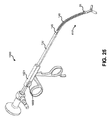
実装によっては、本明細書に記述する軟性−硬性内視鏡は、喉頭鉗子器具へ連結されてもよく、図8〜図25および図29〜図30は、その実装を示す。使用の間、器具のツール部分またはシャフトは、患者の口から喉を介して患者の喉頭腔へ挿入されてもよい。例えば、喉頭鉗子600のブレード619は、除去する必要がある組織の近くに位置合わせされてもよい。鉗子600のブレード619を内視鏡100のレンズ150の直前に位置合わせすることは、医師が、ブレードが組織へ接触する際のブレードおよび喉頭腔を適正に視覚化することを可能にし得る。よって、医師は、ブレード619による組織の把持または切断を見ながら、鉗子600の取っ手629を作動し得る。
Depending on the implementation, the soft-rigid endoscope described herein may be connected to a laryngeal forceps instrument, with FIGS. 8-25 and 29-30 showing the implementation. During use, the tool portion or shaft of the instrument may be inserted from the patient's mouth through the throat into the patient's laryngeal cavity. For example, the
副鼻腔鉗子 Sinus forceps
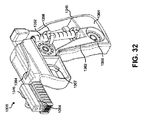
実装によっては、本明細書に記述する軟性−硬性内視鏡は、副鼻腔鉗子器具へ連結されてもよく、図26〜図28は、その実装を示す。使用の間、器具のツール部分またはシャフトは、鼻孔を介して患者の副鼻腔へ挿入されてもよい。例えば、鉗子1100のブレード1119は、除去する必要がある上顎洞内組織の近くに位置合わせされてもよい。副鼻腔鉗子1100のブレード1119を内視鏡100のレンズ150の直前に位置合わせすることは、医師が、ブレードが組織へ接触する際のブレードおよび副鼻腔を適正に視覚化することを可能にし得る。よって、医師は、ブレード1119による組織の把持または切断を見ながら、副鼻腔鉗子1100の取っ手1029を作動し得る。
Depending on the implementation, the soft-rigid endoscope described herein may be connected to a sinus forceps instrument, and FIGS. 26-28 show the implementation. During use, the tool portion or shaft of the instrument may be inserted into the patient's sinuses through the nostrils. For example,
喉頭シリンジガン Laryngeal syringe gun
診療所で行われる内視鏡下注入(例えば、声帯注入)のための注入シリンジガン1300の実装例を、図32〜図41に示す。図示されているように、シリンジガン1300の外側部分は、器具を保持するためのガンハンドル1345と、トリガ機構1357と、内視鏡アタッチメント機構1346と、針1353をルーティングするための1つまたは複数の溝またはチャネル1354とを含んでもよい。シリンジガン1300の内側は、シリンジ1352と、コネクタ1355と、シリンジ1352を保持するクリップ1356と、ホイール1358と、バンド1359と、プランジャ1360と、ゴムストッパ1361とを含んでもよい。
Examples of mounting the
図36および図39に示すように、シリンジガン1300と共に使用される注入針1353は、シリンジガン1300および内視鏡の軟性の遠位端の形状および輪郭に適応するように構成される予め曲げられた、または展性の針であってもよい。針1353は、コネクタ1355を介してシリンジへ連結されてもよい。設定の間、シリンジ1352および針1353は、シリンジを一連のクリップ1356に押し込み、かつ針1353をシリンジガンの上側部分に組み込まれた溝1354に押し込むことによって、シリンジガン1300内の所定位置にロックされてもよい。シリンジ1352は、局所麻酔用ヒドロキシルアペタイト・ペースト、または針先1351により処置部位(例えば、声帯)に注入される他の何らかの液体または物質で満たされてもよい。
As shown in FIGS. 36 and 39, the
シリンジおよび針が所定位置に固定されると、軟性−硬性ハイブリッドスコープが内視鏡アタッチメント機構1346においてガンハンドルに挿入されても、別段で取り付けられてもよい。図34〜図35および図37〜図38に示す例では、内視鏡は、ガン1300の上側部分の内視鏡アタッチメント機構1346へ、先に述べた挿入型ラチェット機構と同様の方法で取り付けられる。図41に示す例では、内視鏡は、ガンの一部分である内視鏡アタッチメント機構へ、図21を参照して先に述べたトップダウン型ラチェット機構と同様の方法で取り付けられる。内視鏡をシリンジガンへ取り付けるには、他のアタッチメント機構が使用されてもよい。内視鏡の軟性の遠位端1348は、針シャフト1349の湾曲を、軟性の遠位端1348の端に位置づけられる対物レンズ1350が針先1351に近接して位置合わせされるように辿ってもよい。スコープの軟性部分は、ある実施形態(例えば、図34〜図36)では、製造された針1353に取り付けられる一連の金属ループ1329に通されてもよい。先に示唆したように、スコープの遠位を針に取り付けるための他の実装も想定される。図示されている構成では、針先1351が粘膜下組織へ進入する際の針先の直接的視覚化が、取り付けられた軟性−硬性ハイブリッド内視鏡を介して可能にされ得る。
Once the syringe and needle are fixed in place, the soft-rigid hybrid scope may be inserted into the gun handle in the
シリンジガン1330の全てのコンポーネントが組み立てられると、シリンジガンは、連結された内視鏡と共に、片手で保持されかつ位置合わせされ得、同時にもう一方の手を使って舌が安定されて伸ばされ、または他の何らかの作業が行われる。トリガ機構1357は、起動されると、薄くて引き締まった軟性のバンドまたはベルト1359(例えば、金属バンド)へ連結された1つまたは2つの円形ホイール1358を回転させ得る。(下側の第2のホイールの周りを回った後の)バンドの遠位端において、バンドは、針アタッチメントとは反対側の端で、シリンジ1352内に組み込まれるゴムストッパ1361と正反対にかつこれと接触して位置合わせされた円筒形の金属プランジャ1360(図37)へ連結される。トリガが押し下げられる毎に、プランジャ1360が予め決められた距離だけシリンジ内へ前進し得、これにより、シリンジ1352内のゴムストッパ1361が近位へ動かされ、よって、予め決められた量(例えば、約0.1cc)の物質が針先1351から注入部位(例えば、喉頭組織)へ計量分配される。
Once all the components of the syringe gun 1330 have been assembled, the syringe gun can be held and aligned with one hand, along with the connected endoscope, while at the same time the tongue is stabilized and stretched with the other hand. Or some other work is done. When activated, the
バンドが回って通るホイール1358の一方または双方は、電動式であってもよく、かつ滑りを防ぐためにバンド1359の長さに沿って穿孔1365と相互作用する歯1364を含んでもよい。バンド1359は、シリンジガンの取っ手内の狭い安定溝1362を通過してもよい。溝1362は、取っ手片1364の硬いプラスチックまたは機械加工された金属物質に組み込まれてもよい。実施において、シリンジガン1300の上部は、シリンジ針および内視鏡アタッチメントの真下に、(例えば、ホイールを回転させるためのモータに給電するための)1つまたは複数のバッテリを収容するバッテリ区画を含んでもよい。
One or both of the
使用後、シリンジ1352および針1353は、廃棄されてもよく、よってシリンジガン1300は、後続処置の間に新しいシリンジおよび針を用いて再使用されてもよい。他の機械的に起動される注入機構も、想定される。
After use, the
内視鏡エウスタキオ管バルーン拡張器 Endoscope Eustachian tube balloon dilator
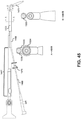
本明細書に記述する軟性−硬性ハイブリッド内視鏡は、エウスタキオ管、副鼻腔、気管および食道の狭窄拡張に使用されるものを含む任意の数のバルーン・カテーテル・デバイスへ取外し可能に連結されてもよい。市場に出回っている現在のバルーン拡張デバイスは、外科医がバルーン拡張カテーテルおよび内視鏡を体腔内へ別々に挿入することを必要とする。これは、2つのデバイスを同時に制御するために両手を必要とし、かつ体腔におけるデバイスプロファイルを増加させ得ることから、問題である。 The flexible-rigid hybrid endoscopes described herein are detachably coupled to any number of balloon catheter devices, including those used for dilation of the eustachian tube, sinuses, trachea and esophagus. May be good. Current balloon dilation devices on the market require surgeons to insert balloon dilatation catheters and endoscopes separately into the body cavity. This is a problem because it requires both hands to control the two devices at the same time and can increase the device profile in the body cavity.
図42〜図45および図68は、本明細書に記述しているような内視鏡を取外し可能に連結するための機構を提供することによってこれらの従来設計を改善する、例示的な内視鏡エウスタキオ管バルーン拡張器1400を示す。図示されているように、拡張器1400は、内視鏡を挿入するためのハウジング1467と、バルーンカテーテル1468を挿入するための中空管材のバルーンカニューレ1466(硬性、半硬性、展性または軟性)とを含んでもよく、カニューレ1466は、遠位セグメント1472を有する。実装において、ハウジング1467は、カニューレ1466へ固定的に連結されても、取外し可能に連結されてもよい。ハイブリッド内視鏡1447は、ハウジング1467の近位開口1469を介して挿入されてもよい。図示されている例において、ハウジング1469は、先に述べたような内視鏡を固定するための挿入型ラチェット機構を含む。他の実装では、他の機構を用いて内視鏡が拡張器へ固定されてもよい。例えば、先に述べたようなトップダウン型ラチェット機構が利用されてもよい(図68)。
42-45 and 68 are exemplary endoscopes that improve these prior art designs by providing a mechanism for removably connecting endoscopes as described herein. Mirror Eustachian
バルーンカテーテルのシャフトに沿って位置決めされるストッパ1470は、シースを介してバルーンを前進させるための簡易グリップを提供し、かつバルーンカテーテルの過度の前進を制限することに役立ち得る。別個の硬い、または軟性のコネクタ1333は、内視鏡の遠位の軟性セグメントをバルーンカニューレ1466の湾曲した遠位のセグメント1472へ固定するために使用され得る。例示されている拡張器は、限られた鼻腔内での空間利用、患者の快適さ、および外科医の器用さを最大化する、片手で1つの器具を扱う技術を可能にし得る。現在利用可能な副鼻腔バルーンカテーテル、例えば、Acclarent Aera(登録商標)も、図42〜図45に示す方法と同様にしてハイブリッドスコープへ取り付けるように適合化される可能性もある。
The
内視鏡気管拡張器 Endoscopic tracheal dilator
時として、患者は、偶発的な気管切開チューブの外れに関連して選択的または緊急に気道障害を呈する。気管切開チューブが誤って取り外されると(抜管)、それが配置された小孔管が収縮することが多く、よって、気管切開チューブの再挿入が妨げられる。チューブの再挿入を強引に試みると、外傷、出血、気道障害が生じ、かつ時にはチューブが皮膚の下かつ気管内腔より外側の軟らかい組織管へ入り、結果的に患者が死亡する可能性がある。現時点で、気管孔狭窄の拡張に使用される確立された方法は、テーパ状のブジー拡張器を利用することである。残念ながら、これらのブジー拡張器(例えば、Cook(登録商標)Medical、Blue Rhino(登録商標))は、通過中に気道を塞ぎ、よって呼吸困難が生じて患者の不安を高める。現在のシステムは、拡張前に気管内腔内の拡張器の適切な位置合わせを視覚的に確認することができない。 Occasionally, patients present with selective or urgent airway obstruction associated with accidental tracheostomy tube detachment. If the tracheostomy tube is accidentally removed (extubation), the small foramen tube in which it is located often contracts, thus preventing reinsertion of the tracheostomy tube. Forcible attempts to reinsert the tube can cause trauma, bleeding, airway obstruction, and sometimes the tube can enter the soft tissue duct under the skin and outside the tracheal lumen, resulting in death of the patient. .. At present, the established method used for dilation of tracheal stenosis is to utilize a tapered bougie dilator. Unfortunately, these bougie dilators (eg, Cook® Medical, Blue Rino®) block the airways during transit, thus causing dyspnea and increasing patient anxiety. Current systems cannot visually confirm the proper alignment of dilators within the tracheal lumen prior to dilation.
図48〜55は、オペレータが気管孔および気管内腔内のバルーン拡張器1477の適正な位置合わせを膨張前に視覚的に確認できるようにする、内視鏡気管拡張器の一実装例を示す。拡張器は、軟性−硬性ハイブリッド内視鏡を器具のバルーンポンプ・ハンドピース1573へ取外し可能に連結するためのトップダウン型ラチェット機構1535を含む。機構1535は、先に述べたトップダウン型ラチェット機構と同様に動作し得る。例えば、これは、内視鏡の硬性の近位アタッチメントセグメントの連続するスロット間のスペーシングに対応する間隔で離隔され得る、離隔されたリッジ1536を含んでもよい。取り付けの間、ボタン1522は、内視鏡の硬性の近位アタッチメントセグメントの溝にロックするように構成されるバーを引っ込めるように作動され得る。この例では、トップダウン型ラチェットアタッチメント機構が示されているが、他の機構を用いて内視鏡が器具へ取外し可能に連結されてもよい。例えば、先に論じた挿入型ラチェット機構が使用されてもよい。
FIGS. 48-55 show an implementation of an endoscopic tracheal dilator that allows the operator to visually confirm the proper alignment of the balloon dilator 1477 in the tracheal foramen and tracheal lumen before expansion. .. The dilator includes a top-
バルーンポンプ・ハンドピース1573は、作動されるとバルーンポンプ・ハンドル1573の基部における接続部1576へ連結する軟性チューブ1575を介して空気または液体(例えば、水または生理食塩水)を圧送するポンプハンドル1574を備えてもよい。加圧された空気または流体は、次に、ポンプハンドル接続部1576の基部から軟性チューブ1575を介して、中空の内側カニューレ1578へ周方向に取り付けられる遠位バルーン1577へ伝達され得る。圧力は、ポンプハンドル1573に(例えば、図示されている例における左上部分に)組み込まれる圧力計1590によって測定されてもよい。
The
圧力計の直下には、作動されるとバルーンから圧力を解放し得るボタン1591が存在してもよい。中空の内側カニューレは、その近位端に開口1583(図54)を有してもよく、ハイブリッド内視鏡の軟性の遠位端は、この開口1583を介して挿入されかつ、遠位端の先端が中空の内側カニューレの遠位部1579を出るまで前進されてもよい。中空の内側カニューレ1578およびバルーン1577内に含まれるスコープの遠位端は、気管の管腔が視覚化されるまで気管孔狭窄(外皮と前気管壁との間の軟組織部位)を介して前進されてもよい。気管内部における内側カニューレの適正な位置合わせが確認されると、内視鏡は、引き抜かれてもよく、よって患者は、中空の内側カニューレ1578を介して呼吸し続けることができる。
Directly below the pressure gauge may be a
この例では、高圧バルーン拡張器が中空の内側カニューレ1578の外部にあることから、患者は、ポンプハンドルの作動によりバルーンが膨張される間も中空の内側カニューレを介して安全に呼吸し続け得る。バルーン1577の直近には、膨張の間に装置を手動で安定させる手助けをしかつ気道内部のバルーンまたはカニューレの不注意による前進のしすぎを防止するために、小さい取外し可能なストッパ1584(図51〜図53)が置かれてもよい。小さい湾曲した軟性ばね1585は、中空の内側カニューレ1587上に位置合わせされるストッパクランプの拡大を可能にし得る。ストッパ上の横方向の突起1586同士を締め付けると、ばねが作動して、ストッパ1584をカニューレから取り外すことができるようになり得る。軟性チューブをハンドル基部のカップリングへ取り付ける前に、管材が気管切開チューブの内腔を完全に通過するように、別個の気管切開チューブ1582および1595が管材を超えて前進されてもよい。
In this example, since the high pressure balloon dilator is outside the hollow
この実装の場合、#4の気管切開チューブが使用されてもよいが、軟性の管材および中空の内側カニューレの口径を収容するに足る小さい内径を有する如何なる気管切開チューブも使用され得る。小孔がバルーンで拡張されると、ストッパクランプ1584が取り外され得、よって気管切開チューブが軟性の管材および内側カニューレを超え、拡張された小孔を介して気管内腔へと前進され得る。チューブは、次に、不注意による抜管を防ぐために固定されてもよい。
For this implementation, # 4 tracheostomy tubing may be used, but any tracheostomy tubing with a small inner diameter sufficient to accommodate the caliber of the soft tubing and hollow inner cannula can be used. Once the pit is dilated with a balloon, the
この目的に沿った拡張用気管切開チューブ1595を、図55に示す。拡張用気管切開チューブ1595は、独立して使用される可能性もあれば、小孔を最初のバルーン膨張により提供される直径を超えてさらに拡張させるために使用される可能性もある。例えば、より大きい直径である#6または#8の気管切開チューブが必要である場合、これが必要となり得る。拡張用チューブは、そのシャフト上に、2つの別々のバルーン、すなわち遠位のバルーン1580および近位のバルーン1581、を有してもよい。遠位のバルーン1580は、既に市販されているカフ付き気管切開チューブと同様の低圧カフであってもよい。この遠位のバルーン/カフは、典型的には、気管内腔内の一点まで前進され、その後、膨張されてもよい。標準的な気管切開術設計と同様に、低圧膨張ポート1588を介して膨張されると、遠位のカフは、気管壁に対するシールを生成することにより気道を保護するように機能し得る。
A
近位のバルーン1581は、その非膨張状態において接着性を維持しかつチューブ1582と同一平面にあり得る高圧バルーンであってもよい。チューブが(膨張していない近位および遠位のバルーンと共に)最近に拡張された気管孔を介して前進されると、近位の高圧バルーンは、膨張ポート1589を介してより大きい直径まで膨張される可能性もあり、これにより、気管孔の直径が増大される。気管孔が最大限に拡張されると、近位のバルーン1581が収縮されかつ二重のバルーンチューブが取り外されてもよく、よってより大きい直径の、より従来的な気管切開チューブがその場所に挿入されることも可能である。これは、気管切開チューブのアップサイジングと呼ばれ、新生児、または十分な人工呼吸器サポートまたは気管/肺の衛生状態を提供するには不十分なサイズまたは直径であるより小さい気管切開チューブを有する慢性的な人工呼吸器患者に有益であり得る。
内視鏡経口的食道バルーン拡張器 Endoscopic oral esophageal balloon dilator
頸部食道狭窄または慢性輪状咽頭痙攣に伴って嚥下が困難な患者は、食道拡張を必要とすることが多い。食道拡張は、診療所環境で行われることはほとんどなく、ほぼ常に、胃腸科専門医により鎮静麻酔下で行われる。食道拡張は通常、食道胃十二指腸内視鏡検査(EGD)と同時に行われる。EGDは、時には必要であるが、患者が拡張を必要とする度に必要なものではない。これは、特に、放射線療法または慢性咽喉頭逆流に続いて起こる場合もあるために経時的に複数の拡張を必要とする患者に当てはまる。現在の食道拡張技術は、漸増的なサイズのブジーカテーテルおよび食道バルーンカテーテルを用いる連続的拡張を伴い得る。 Patients who have difficulty swallowing due to cervical esophageal stricture or chronic cricopharyngeal spasm often require esophageal dilatation. Esophageal dilation is rarely performed in a clinic environment and is almost always performed by a gastroenterologist under sedative anesthesia. Esophageal dilatation is usually performed at the same time as esophagogastroduodenal endoscopy (EGD). EGD is sometimes needed, but not every time the patient needs dilation. This is especially true for patients who require multiple dilations over time as they may follow radiation therapy or chronic laryngopharyngeal reflux. Current esophageal dilation techniques can involve continuous dilation with incrementally sized bougie catheters and esophageal balloon catheters.
図56〜図61は、本開示による、新規の内視鏡経口的食道バルーン拡張器システムの実装を示す。このシステムは、診療所環境において内視鏡ガイド下で、かつ麻酔または付随するEGD処置を必要とすることなく実行される可能性もある、簡単、低コスト、安全かつ効果的な頸管バルーン食道拡張を見込み得る。図示されていない別の実装は、経口的拡張器に類似する概念の内視鏡経鼻食道バルーン拡張器を含んでもよい。 56-61 show the implementation of a novel endoscopic oral esophageal balloon dilator system according to the present disclosure. This system is a simple, low-cost, safe and effective cervical balloon esophageal dilatation that can be performed in a clinic environment under endoscopic guidance and without the need for anesthesia or associated EGD procedures. Can be expected. Another implementation not shown may include an endoscopic nasal esophageal balloon dilator with a concept similar to an oral dilator.
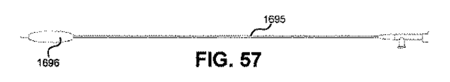
図56〜図59を参照すると、図示されているような内視鏡経口的食道バルーン拡張器システム1600は、ハンドピース1693へ取外し可能に連結される軟性−硬性ハイブリッド内視鏡1692を含む。ハンドピース1693は、使い捨てであっても、再使用可能であってもよい。図56〜図59の例において、ハンドピース1693は、内視鏡1692の硬性の近位端を受け入れるためのレバー式トップダウン型ラチェットアタッチメント機構1699を含む。機構1699は、先に論じたレバー式トップダウン型ラチェットアタッチメント機構と同様であってもよい。例えば、機構1699は、内視鏡の硬性の近位アタッチメントセグメントのスロットを受け入れるためのリッジ1698と、ボタン1697を押すことにより内視鏡の溝から引っ込められるレバーとを含んでもよい。図60〜図61は、アタッチメント機構の別の例−挿入型ラチェット機構1799−を示し、これは、内視鏡経口的食道バルーン拡張器システムのハンドピース1793を内視鏡の硬性の近位端へ取外し可能に連結するために使用されてもよい。機構1799は、先に論じた挿入型ラチェットアタッチメント機構と同様であってもよい。他の実装では、他のアタッチメント機構を用いて、本開示による軟性−硬性ハイブリッド内視鏡が内視鏡経口的食道バルーン拡張器システムへ取外し可能に連結されてもよい。
Referring to FIGS. 56-59, the endoscopic oral esophageal
ハンドピース1693からは、硬性、展性または軟性である可能性もある中空のチューブ1694が延びてもよい。中空のチューブ1694の口径は、薄い軟性のバルーンカテーテル1695を内部に収容するに足るものであってもよい。軟性のバルーンカテーテル1695は、その遠位端に、膨張可能なバルーン1696を有してもよい。バルーンは、その非膨張状態において、ハンドピースの側面にある穴1697を介して前進される可能性もある。軟性のバルーンカテーテルは、バルーンが中空のチューブの遠位端を越えて延びることを可能にするに足る長さであってもよい。ハイブリッド内視鏡の軟性の端は、中空のチューブ1694の湾曲した側面へ、図46〜図47に示すように、取外し可能な硬性または軟性のインサートによって取り付けられてもよい。内視鏡は、中空のチューブの遠位端から頸部食道内へ進むにつれてバルーン1696およびバルーンカテーテル1695を視覚化するために使用されてもよい。カテーテル上の、バルーンに近位の小さいマーキングは、バルーン膨張に先行してカテーテルを食道に挿入する適正な距離を内視鏡によって概算する手助けをするために使用されてもよい。図56〜図61に示すような気管バルーンポンプ・ハンドピースは、食道拡張器と共に使用するように適合化される可能性もあり、かつ片手による操作を促進し得る。
A
本明細書に記述する内視鏡、アタッチメント機構および器具は、概して耳鼻咽喉科(耳、鼻および喉、ENT)の外科的用途に関連して説明されているが、本明細書に開示する内視鏡がこれらの用途に限定される必要のないことは、留意されるべきである。例えば、本明細書に記述する内視鏡は、一般外科、胃腸病学、呼吸器学、泌尿器科学、形成外科学、神経外科学および整形外科学等の他の外科および医学専門分野において、外科ステープリング等の用途に利用される可能性もある。本明細書に開示する技術の商業的な、非外科的用途も適用可能である。 The endoscopes, attachment mechanisms and instruments described herein are generally described in the context of otolaryngology (ear, nose and throat, ENT) surgical applications, but are disclosed herein. It should be noted that the endoscope need not be limited to these applications. For example, the endoscopes described herein are surgical in other surgical and medical disciplines such as general surgery, gastrointestinal illness, respiratory science, urology, plastic surgery, neurosurgery and orthopedic surgery. It may also be used for applications such as surgery. Commercial and non-surgical applications of the techniques disclosed herein are also applicable.
以上、様々な例示的実装および実装に関連して説明したが、個々の実装のうちの1つまたはそれ以上において説明されている様々な特徴、態様および機能の適用可能性は、それらが説明されている特定の実装に限定されるものではなく、単独または様々な組合せで、用途の他の実装のうちの1つまたはそれ以上へ、このような実装の記載の有無に関わらず、かつこのような特徴が、記述されている実装の一部として提示されているか否かに関わらず適用され得ることは、理解されるべきである。したがって、本出願の広さおよび範囲は、これまでに述べた例示的実装の何れによっても限定されるべきではない。 Although described above in connection with various exemplary implementations and implementations, the applicability of the various features, aspects and features described in one or more of the individual implementations has been described. Not limited to a particular implementation, either alone or in various combinations, to one or more of the other implementations of the application, with or without description of such an implementation, and in this way. It should be understood that the features can be applied whether or not they are presented as part of the implementation described. Therefore, the breadth and scope of this application should not be limited by any of the exemplary implementations described so far.
前述の概念の全ての組合せは(このような概念が相互に矛盾するものでない限り)、本明細書に開示する発明の主題の一部であることが企図される点は、認識されるべきである。具体的には、本開示の最後に現出する特許請求の範囲に記載された主題の全ての組合せは、本明細書に開示する発明の主題の一部であることが企図される。 It should be acknowledged that all combinations of the aforementioned concepts (unless such concepts are mutually contradictory) are intended to be part of the subject matter of the invention disclosed herein. be. Specifically, all combinations of the subjects described in the claims appearing at the end of the present disclosure are intended to be part of the subject matter of the invention disclosed herein.
特許請求の範囲を含む本開示を通して使用される「略」および「約」という用語が、処理の変異等に記述する僅かな変動を記述しかつ説明するために使用されることは、認識されるべきである。例えば、これらの用語は、±2%以下等、±1%以下等、±0.5%以下等、±0.2%以下等、±0.1%以下等、±0.05%以下等の±5%以下を指し得る。 It is acknowledged that the terms "abbreviation" and "about" used throughout this disclosure, including the claims, are used to describe and explain the slight variations described in processing variations, etc. Should be. For example, these terms are ± 2% or less, ± 1% or less, ± 0.5% or less, ± 0.2% or less, ± 0.1% or less, ± 0.05% or less, etc. Can point to ± 5% or less of.
適用可能である限りにおいて、本明細書における「第1の」、「第2の」、「第3の」、他といった用語は、単に、これらの用語によって説明される個々のオブジェクトを別個のエンティティとして示すために使用されるものであって、本明細書において別段の明記のない限り、発生順の意味をもたせるためのものではない。 To the extent applicable, terms such as "first," "second," "third," and others herein simply refer to the individual objects described by these terms as separate entities. It is used to indicate as, and is not intended to have the meaning of the order of occurrence unless otherwise specified in the present specification.
本文書で使用している用語および言い回し、およびこれらの変形は、別段の明記のない限り、限定ではなく制約のないものとして解釈されるべきである。上記の例として、「を含む」という用語は、「を限定なしに含む」またはこの類を意味するものとして読み取られるべきであり、 「例」という用語は、論じているアイテムの幾つかのインスタンスを提供するために使用されるものであって、その網羅的または限定的なリストを提供するものではなく、「1つの」または「ある」という不定冠詞は、「少なくとも1つの」、「1つまたは複数の」またはこの類を意味するものとして読み取られるべきであり、「従来的」、「伝統的」、「一般的」、「標準的」、「既知の」といった形容詞および類似の意味をもつ用語は、記述されるアイテムを所与の時間期間において、または所与の時点において利用可能なアイテムに限定するものとして解釈されるべきではなく、代わりに、現在または将来のいつでも利用可能な、または知られるものであり得る従来的、伝統的、一般的または標準的な技術を包含するものとして読み取られるべきである。同様に、本文書は、一般的な当業者に明らかである、または知られると思われる技術に言及しているが、このような技術には、現在または将来のあらゆる時点で当業者に明らかな、または知られる技術が包含される。 The terms and phrases used in this document, and their variations, should be construed as unrestricted and unrestricted, unless otherwise stated. As an example above, the term "contains" should be read as meaning "contains without limitation" or the like, and the term "example" is some instance of the item being discussed. The indefinite adjective "one" or "is" is used to provide "at least one", "one", not to provide an exhaustive or limited list thereof. Or should be read as meaning "plurality" or the like, with adjectives such as "conventional", "traditional", "general", "standard", "known" and similar meanings. The term should not be construed as limiting the items described to those items available at a given time period or at a given point in time, instead, they are available now or at any time in the future, or It should be read as embracing conventional, traditional, general or standard techniques that may be known. Similarly, this document refers to techniques that may be apparent or known to those of ordinary skill in the art, but such techniques will be apparent to those of ordinary skill in the art at any time in the present or future. , Or known techniques are included.
一部のインスタンスにおける「1つまたは複数の」、「少なくとも」、「但しこれに限定されない」または他の同様の言い回し等の拡大的な単語および言い回しの存在は、このような拡大的言い回しが存在しないようなインスタンスでは、より狭義の事例が意図または要求されることを意味するものと解釈されてはならない。「モジュール」という用語の使用は、モジュールの一部として記述または主張されるコンポーネントまたは機能が全て共通のパッケージ内に構成されることを含意しない。実際のところ、モジュールの様々なコンポーネントの何れかまたは全ては、制御論理であるか他のコンポーネントであるかに関わりなく、単一のパッケージに組み合わされることも、別々に保全されることも可能であり、かつさらに、複数のグルーピングまたはパッケージに、または複数のロケーションに渡って分散されることが可能である。 The presence of expanded words and phrases such as "one or more", "at least", "but not limited to" or other similar phrases in some instances is such an expanded phrase exists. Instances that do not should be construed as meaning that a narrower case is intended or required. The use of the term "module" does not imply that all components or features described or claimed as part of a module are configured in a common package. In fact, any or all of the various components of a module, whether control logic or other components, can be combined into a single package or preserved separately. Yes, and can be distributed across multiple groupings or packages, or across multiple locations.
さらに、本明細書に記載する様々な実装は、例示的なブロック図、フローチャートおよび他の図に関連して説明されている。本文書を読めば一般的な当業者には明らかとなるであろうが、図示された実装およびそれらの様々な代替実装は、図示された例に限定されることなく実装されてもよい。例えば、ブロック図およびそれに付随する説明は、特定の構造または構成を指令するものとして解釈されるべきではない。 In addition, the various implementations described herein are described in connection with exemplary block diagrams, flowcharts and other diagrams. As will be apparent to those skilled in the art by reading this document, the illustrated implementations and their various alternative implementations may be implemented without limitation to the illustrated examples. For example, block diagrams and accompanying descriptions should not be construed as directing a particular structure or configuration.
以上、本開示の様々な実装について述べたが、これらの実装は、単に例示として提示されたものであって限定でない点は、理解されるべきである。同様に、様々な図は、本開示の例示的な構造または他の構成を示すものであり得、これは、本開示に包含されることが可能な特徴および機能の理解を支援するために行われている。本開示は、説明された例示的な構造または構成に限定されるものではなく、所望される特徴は、様々な代替の構造および構成を用いて実装されることが可能である。実際に、当業者には、本開示の所望される特徴を実装するために、代替の機能的、論理的または物理的な区分および構成がどのように実装され得るかが明らかであろう。また、本明細書に示されているもの以外の多くの異なる構成モジュール名を、様々なパーティションに適用することができる。さらに、フロー図、動作の説明および方法のクレームに関連して、本明細書に提示されているステップの順序は、コンテキストによる別段の指摘のない限り、様々な実装が、列挙されている機能を同じ順序で実行するように実装されることを義務づけるものではない。 Although the various implementations of the present disclosure have been described above, it should be understood that these implementations are merely exemplary and not limiting. Similarly, various diagrams may represent exemplary structures or other configurations of the present disclosure, which are lines to assist in understanding the features and functions that may be included in the present disclosure. It has been. The present disclosure is not limited to the exemplary structures or configurations described, and the desired features can be implemented using a variety of alternative structures and configurations. In fact, it will be apparent to those skilled in the art how alternative functional, logical or physical compartments and configurations can be implemented to implement the desired features of the present disclosure. Also, many different configuration module names other than those shown herein can be applied to the various partitions. In addition, in connection with flow diagrams, behavioral descriptions and method claims, the order of steps presented herein provides functionality for which various implementations are listed, unless otherwise indicated by the context. It does not require that it be implemented to run in the same order.
Claims (21)
硬性の近位端であって、該硬性の近位端は、前記内視鏡をある器具の取っ手部分へ取外し可能に連結するための硬性の近位アタッチメントセグメントを備え、前記硬性の近位アタッチメントセグメントは、
前記硬性の近位アタッチメントセグメントの表面に沿って長手方向に離隔された複数のスロットであって、前記複数のスロットは前記器具の前記取っ手部分のリッジへ挿入される複数のスロットと、
前記硬性の近位アタッチメントセグメントの前記表面に沿って長手方向に延びる複数の溝であって、前記複数の溝は、前記硬性の近位アタッチメントセグメントの前記表面の周囲に、周方向に離隔され、前記複数のスロットおよび前記複数の溝は、前記内視鏡が複数の周方向および長さ方向位置で、前記器具の前記取っ手部分に取り外し可能に連結可能であるように構成される、複数の溝と、を備える、硬性の近位端と、
患者の体腔に挿入されて体腔を撮像するための軟性の遠位端とを備える、内視鏡。 It ’s an endoscope,
A rigid proximal end, the rigid proximal end comprising a rigid proximal attachment segment for detachably connecting the endoscope to a handle portion of an instrument, said rigid proximal attachment. The segment is
A plurality of slots longitudinally spaced along the surface of the rigid proximal attachment segment, wherein the plurality of slots are a plurality of slots inserted into the ridge of the handle portion of the instrument.
A plurality of grooves extending longitudinally along the surface of the rigid proximal attachment segment, the plurality of grooves being circumferentially spaced around the surface of the rigid proximal attachment segment. The plurality of slots and the plurality of grooves are configured such that the endoscope can be removably connected to the handle portion of the instrument at a plurality of circumferential and longitudinal positions. And, with a rigid proximal end,
An endoscope that is inserted into the patient's body cavity and has a flexible distal end for imaging the body cavity.
前記硬性の近位端の近位部分へ連結されるアイピースまたはカメラアッセンブリとをさらに備える、請求項1に記載の内視鏡。 A lens and illuminant positioned at the tip of the soft distal end, wherein the illuminant illuminates a body cavity and the lens collects light reflected by the body cavity.
The endoscope according to claim 1, further comprising an eyepiece or a camera assembly connected to the proximal portion of the rigid proximal end.
前記ハウジングに近接するコネクタであって、前記内視鏡を制御ボックスへ接続するコネクタケーブルへ取外し可能に連結するコネクタとをさらに備え、前記制御ボックスは、バッテリパック、画像センサおよびWIFIモジュールのうちの1つまたはそれ以上を備える、請求項1に記載の内視鏡。 A housing that is integrated into the proximal portion of the rigid proximal end and that comprises a lighting device.
A connector close to the housing, further comprising a connector that removably connects the endoscope to a connector cable that connects the endoscope to the control box, the control box of which is a battery pack, an image sensor, and a WIFI module. The endoscope according to claim 1, comprising one or more.
前記軟性の遠位端は、2.5cm〜15cmの長手方向長さおよび1mm〜4mmの厚さを有する、請求項1に記載の内視鏡。 The rigid proximal end has a longitudinal length of 10 cm to 20 cm and a thickness of 0.5 cm to 2 cm, and
The endoscope according to claim 1, wherein the soft distal end has a longitudinal length of 2.5 cm to 15 cm and a thickness of 1 mm to 4 mm.
取っ手部分とツール部分を備える器具と、
内視鏡であって、
前記器具の前記ツール部分に取り外し可能に連結するための軟性の遠位端と、
前記器具の前記取っ手部分に取り外し可能に連結するための硬性の近位端と、を含み、前記硬性の近位端は長手方向に離隔される複数のスロットと、少なくとも1つの長手方向溝とを備え、前記器具の前記取っ手部分は、長手方向に離隔される前記スロットと位置合わせするように複数の離隔されたリッジを有する細長いチャネルと、前記長手方向溝を係合する引込み式内部突起と、を備える内視鏡と、を備え、
前記器具は前記器具の取っ手部分の作動部分より上に位置決めされるチャネルハウジングを備え、前記チャネルハウジングは、前記引込み式内部突起を作動させる押下げ可能なボタンを備える、内視鏡システム。 It ’s an endoscopic system,
An instrument with a handle and a tool,
It ’s an endoscope,
With a flexible distal end for detachable connection to the tool portion of the instrument,
A rigid proximal end for removably connecting to the handle portion of the instrument, the rigid proximal end having a plurality of slots spaced longitudinally and at least one longitudinal groove. The handle portion of the device comprises an elongated channel having a plurality of isolated ridges to align with the slot isolated in the longitudinal direction, and a retractable internal projection engaging the longitudinal groove. Equipped with an endoscope, equipped with,
An endoscopic system comprising a channel housing that is positioned above an actuating portion of a handle portion of the instrument, the channel housing comprising a push-down button that activates the retractable internal projection.
Priority Applications (2)
| Application Number | Priority Date | Filing Date | Title |
|---|---|---|---|
| JP2021149888A JP7313718B2 (en) | 2017-04-20 | 2021-09-15 | Flexible-rigid hybrid endoscope and instrument attachment |
| JP2023110381A JP2023145461A (en) | 2017-04-20 | 2023-07-05 | Flexible-rigid hybrid endoscope and instrument attachments |
Applications Claiming Priority (5)
| Application Number | Priority Date | Filing Date | Title |
|---|---|---|---|
| US201762487903P | 2017-04-20 | 2017-04-20 | |
| US62/487,903 | 2017-04-20 | ||
| US201862633540P | 2018-02-21 | 2018-02-21 | |
| US62/633,540 | 2018-02-21 | ||
| PCT/US2018/028663 WO2018195489A1 (en) | 2017-04-20 | 2018-04-20 | Flexible-rigid hybrid endoscope and instrument attachments |
Related Child Applications (1)
| Application Number | Title | Priority Date | Filing Date |
|---|---|---|---|
| JP2021149888A Division JP7313718B2 (en) | 2017-04-20 | 2021-09-15 | Flexible-rigid hybrid endoscope and instrument attachment |
Publications (3)
| Publication Number | Publication Date |
|---|---|
| JP2020517408A JP2020517408A (en) | 2020-06-18 |
| JP2020517408A5 JP2020517408A5 (en) | 2021-05-27 |
| JP6951000B2 true JP6951000B2 (en) | 2021-10-20 |
Family
ID=62117076
Family Applications (3)
| Application Number | Title | Priority Date | Filing Date |
|---|---|---|---|
| JP2020507507A Active JP6951000B2 (en) | 2017-04-20 | 2018-04-20 | Soft-rigid hybrid endoscope and instrument attachment |
| JP2021149888A Active JP7313718B2 (en) | 2017-04-20 | 2021-09-15 | Flexible-rigid hybrid endoscope and instrument attachment |
| JP2023110381A Pending JP2023145461A (en) | 2017-04-20 | 2023-07-05 | Flexible-rigid hybrid endoscope and instrument attachments |
Family Applications After (2)
| Application Number | Title | Priority Date | Filing Date |
|---|---|---|---|
| JP2021149888A Active JP7313718B2 (en) | 2017-04-20 | 2021-09-15 | Flexible-rigid hybrid endoscope and instrument attachment |
| JP2023110381A Pending JP2023145461A (en) | 2017-04-20 | 2023-07-05 | Flexible-rigid hybrid endoscope and instrument attachments |
Country Status (9)
| Country | Link |
|---|---|
| US (2) | US10512391B2 (en) |
| EP (4) | EP3612077B1 (en) |
| JP (3) | JP6951000B2 (en) |
| CN (2) | CN216167334U (en) |
| AU (2) | AU2018255426B2 (en) |
| CA (1) | CA3060092A1 (en) |
| ES (1) | ES2900583T3 (en) |
| SG (2) | SG11201909114XA (en) |
| WO (2) | WO2018195489A1 (en) |
Families Citing this family (23)
| Publication number | Priority date | Publication date | Assignee | Title |
|---|---|---|---|---|
| US20190217034A1 (en) * | 2016-09-27 | 2019-07-18 | Andrew Maslow | Intubating endoscopic device |
| SG11201909114XA (en) * | 2017-04-20 | 2019-11-28 | Resnent Llc | Flexible-rigid hybrid endoscope and instrument attachments |
| USD921198S1 (en) * | 2018-02-02 | 2021-06-01 | Ferton Holding S.A. | Medical equipment |
| KR102149676B1 (en) * | 2018-03-20 | 2020-09-04 | 가톨릭대학교 산학협력단 | Openable spinal endoscope apparatus |
| WO2020068899A1 (en) * | 2018-09-25 | 2020-04-02 | Yoojeong Kim | Multimodal endoscope and methods of use |
| CN109349989B (en) * | 2018-12-10 | 2020-11-10 | 郑州大学第一附属医院 | Multifunctional hard endoscope for ear |
| CN109645946A (en) * | 2018-12-29 | 2019-04-19 | 上海交通大学医学院附属第九人民医院 | A kind of bottleneck throat endoscopic surgery device |
| CN110745323B (en) * | 2019-10-31 | 2021-07-02 | 中国人民解放军陆军军医大学第一附属医院 | Opening device for infusion bag |
| US20220008068A1 (en) * | 2019-12-13 | 2022-01-13 | Dinesh Vyas | Stapler apparatus and methods for use |
| US20230056943A1 (en) * | 2019-12-13 | 2023-02-23 | Dinesh Vyas | Stapler apparatus and methods for use |
| US11589864B2 (en) | 2019-12-13 | 2023-02-28 | Dinesh Vyas | Stapler apparatus and methods for use |
| US20210228412A1 (en) * | 2020-01-24 | 2021-07-29 | Spiral Therapeutics Inc. | Devices, systems, and methods for otology |
| GB202003311D0 (en) * | 2020-03-06 | 2020-04-22 | Univ Malta | Retractor device for transoral insertion site, and method of viewing a surgical site |
| TWD218084S (en) * | 2020-04-28 | 2022-04-11 | 仁寶電腦工業股份有限公司 | Connecting base |
| CN111671379A (en) * | 2020-06-08 | 2020-09-18 | 北京凡星光电医疗设备股份有限公司 | Disposable medical examination device for endoscope |
| RU202396U1 (en) * | 2020-09-25 | 2021-02-16 | Сергей Александрович Лузгин | DEVICE FOR INSPECTION OF NATURAL CAVITY |
| WO2022082022A2 (en) * | 2020-10-16 | 2022-04-21 | Resnent, Llc | Endoscope attachment mechanisms and methods of use |
| US20220160213A1 (en) * | 2020-11-23 | 2022-05-26 | United States Endoscopy Group, Inc. | Endoscopic device with additional channel |
| CA3224240A1 (en) | 2021-06-29 | 2023-01-05 | Willard S. Noyes | Articulating cannula with endoscope attachment |
| CN113576371B (en) * | 2021-07-02 | 2024-03-15 | 柏为(武汉)医疗科技股份有限公司 | Endoscope and detecting instrument |
| WO2023064636A1 (en) | 2021-10-15 | 2023-04-20 | Resnent, Llc | Detachable endoscope shaft |
| WO2023192353A1 (en) * | 2022-03-29 | 2023-10-05 | Resnent, Llc | Endoscopic retractable syringe device |
| DE102022113124A1 (en) | 2022-05-24 | 2023-11-30 | Joimax Gmbh | Handle for medical endoscopes and endoscope system |
Family Cites Families (38)
| Publication number | Priority date | Publication date | Assignee | Title |
|---|---|---|---|---|
| US4459984A (en) * | 1982-09-15 | 1984-07-17 | Liegner Kenneth B | Speaking tracheostomy tube |
| JPS6048011A (en) * | 1983-08-27 | 1985-03-15 | Olympus Optical Co Ltd | Endoscope device |
| JPH0798049B2 (en) * | 1987-03-19 | 1995-10-25 | オリンパス光学工業株式会社 | Intracorporeal hyperthermia treatment device |
| FR2640389B1 (en) * | 1988-12-12 | 1992-10-02 | Fibres Optiques Rech Technolo | RIGID VIDEO ENDOSCOPES |
| JP2598603B2 (en) * | 1993-01-13 | 1997-04-09 | イマジン メディカル インコーポレイテッド | Endoscope |
| US7037258B2 (en) * | 1999-09-24 | 2006-05-02 | Karl Storz Imaging, Inc. | Image orientation for endoscopic video displays |
| US8313496B2 (en) * | 2001-02-02 | 2012-11-20 | Lsi Solutions, Inc. | System for endoscopic suturing |
| US7815565B2 (en) * | 2003-05-16 | 2010-10-19 | Ethicon Endo-Surgery, Inc. | Endcap for use with an endoscope |
| US7641668B2 (en) * | 2003-05-16 | 2010-01-05 | Scimed Life Systems, Inc. | Fluid delivery system and related methods of use |
| JP3823321B2 (en) * | 2003-12-25 | 2006-09-20 | 有限会社エスアールジェイ | Balloon control device |
| EP1719445A4 (en) * | 2004-02-16 | 2012-01-11 | Olympus Corp | Endoscope device |
| DE602005025456D1 (en) * | 2004-03-19 | 2011-02-03 | Olympus Corp | ENDOSCOPE BALLOON CONTROL DEVICE |
| JP4365860B2 (en) * | 2004-04-12 | 2009-11-18 | オリンパス株式会社 | Endoscope device |
| US7566300B2 (en) * | 2004-04-15 | 2009-07-28 | Wilson-Cook Medical, Inc. | Endoscopic surgical access devices and methods of articulating an external accessory channel |
| US9089258B2 (en) * | 2004-04-21 | 2015-07-28 | Acclarent, Inc. | Endoscopic methods and devices for transnasal procedures |
| US7520854B2 (en) * | 2004-07-14 | 2009-04-21 | Olympus Corporation | Endoscope system allowing movement of a display image |
| EP1841353A4 (en) * | 2004-12-28 | 2011-09-21 | Patrick C Melder | Endoscopic imaging system |
| JP4772446B2 (en) * | 2005-09-30 | 2011-09-14 | オリンパスメディカルシステムズ株式会社 | Endoscope insertion aid and endoscope apparatus |
| US9486126B2 (en) * | 2008-06-17 | 2016-11-08 | Apollo Endosurgery, Inc. | Endoscopic helix tissue grasping device |
| WO2010027109A1 (en) * | 2008-09-08 | 2010-03-11 | Fujifilm Corporation | Endoscope system, method of using the same, assisting tool and adapter |
| RU2506056C2 (en) * | 2008-09-18 | 2014-02-10 | Аккларент, Инк. | Methods and apparatus for treating ear, nose and throat diseases |
| US20100125165A1 (en) * | 2008-11-19 | 2010-05-20 | Yuichi Torii | Endoscope system and assist device |
| US20110028785A1 (en) * | 2009-07-31 | 2011-02-03 | There In One Enterprises Co., Ltd. | Endoscope with adjustable viewing angle |
| JP2011045525A (en) * | 2009-08-27 | 2011-03-10 | Fujifilm Corp | Endoscope |
| JP2011120790A (en) * | 2009-12-11 | 2011-06-23 | Olympus Corp | Head-mounted video display device and head-mounted video display system |
| JP5422634B2 (en) | 2011-11-18 | 2014-02-19 | 富士フイルム株式会社 | Endoscope insertion aid and endoscope system |
| US9408955B2 (en) * | 2013-03-15 | 2016-08-09 | Acclarent, Inc. | Nasal fluid management device |
| US20140375784A1 (en) * | 2013-06-21 | 2014-12-25 | Omnivision Technologies, Inc. | Image Sensor With Integrated Orientation Indicator |
| WO2015047860A1 (en) * | 2013-09-27 | 2015-04-02 | Acclarent, Inc. | Enhanced gripping features for nasal and paranasal sinus systems |
| JP5847367B1 (en) * | 2014-02-10 | 2016-01-20 | オリンパス株式会社 | Endoscope and holding mechanism for guide member for endoscope |
| US20160000300A1 (en) * | 2014-07-07 | 2016-01-07 | Integrated Medical Systems International, Inc. | System and Method for Wirelessly Transmitting Operational Data From an Endoscope to a Remote Device |
| US10661061B2 (en) * | 2014-09-08 | 2020-05-26 | Sanovas Intellectual Property, Llc | Clearance of sinus ostia blockage |
| US20160106300A1 (en) * | 2014-10-17 | 2016-04-21 | Willard S. Noyes | Flexible Endoscopic Exoskeleton Surgical System |
| EP3232896A1 (en) * | 2014-12-19 | 2017-10-25 | Boston Scientific Scimed, Inc. | Imaging devices and related methods |
| US10493251B2 (en) | 2015-03-30 | 2019-12-03 | Acclarent, Inc. | Handle with features to couple catheter assembly with endoscope and actuate catheter |
| US10932654B2 (en) * | 2015-11-20 | 2021-03-02 | Boston Scientific Scimed, Inc. | Devices and methods for securing auxiliary tools to minimally invasive introduction tools |
| DE102016106518A1 (en) * | 2016-04-08 | 2017-10-12 | Henke-Sass, Wolf Gmbh | Optic system for an endoscope |
| SG11201909114XA (en) * | 2017-04-20 | 2019-11-28 | Resnent Llc | Flexible-rigid hybrid endoscope and instrument attachments |
-
2018
- 2018-04-20 SG SG11201909114X patent/SG11201909114XA/en unknown
- 2018-04-20 WO PCT/US2018/028663 patent/WO2018195489A1/en unknown
- 2018-04-20 SG SG10202103460WA patent/SG10202103460WA/en unknown
- 2018-04-20 CA CA3060092A patent/CA3060092A1/en active Pending
- 2018-04-20 JP JP2020507507A patent/JP6951000B2/en active Active
- 2018-04-20 EP EP18723231.9A patent/EP3612077B1/en active Active
- 2018-04-20 AU AU2018255426A patent/AU2018255426B2/en active Active
- 2018-04-20 EP EP21207855.4A patent/EP3970599B1/en active Active
- 2018-04-20 EP EP21207854.7A patent/EP3970598A1/en active Pending
- 2018-04-20 US US15/958,351 patent/US10512391B2/en active Active
- 2018-04-20 CN CN202120373304.8U patent/CN216167334U/en active Active
- 2018-04-20 CN CN201890000729.0U patent/CN212650807U/en active Active
- 2018-04-20 ES ES18723231T patent/ES2900583T3/en active Active
-
2019
- 2019-10-25 US US16/664,723 patent/US10925467B2/en active Active
-
2020
- 2020-10-16 EP EP20804106.1A patent/EP4048132A1/en active Pending
- 2020-10-16 WO PCT/US2020/056128 patent/WO2021080878A1/en unknown
-
2021
- 2021-09-15 JP JP2021149888A patent/JP7313718B2/en active Active
-
2023
- 2023-07-05 JP JP2023110381A patent/JP2023145461A/en active Pending
- 2023-09-27 AU AU2023237098A patent/AU2023237098A1/en active Pending
Also Published As
| Publication number | Publication date |
|---|---|
| WO2018195489A1 (en) | 2018-10-25 |
| JP7313718B2 (en) | 2023-07-25 |
| AU2018255426A1 (en) | 2019-12-12 |
| EP3970599B1 (en) | 2023-12-13 |
| SG10202103460WA (en) | 2021-05-28 |
| AU2023237098A1 (en) | 2023-10-12 |
| EP3970599C0 (en) | 2023-12-13 |
| CN216167334U (en) | 2022-04-05 |
| US10512391B2 (en) | 2019-12-24 |
| US20180303314A1 (en) | 2018-10-25 |
| WO2021080878A1 (en) | 2021-04-29 |
| US10925467B2 (en) | 2021-02-23 |
| JP2023145461A (en) | 2023-10-11 |
| AU2018255426B2 (en) | 2023-06-29 |
| EP3612077B1 (en) | 2021-11-17 |
| JP2020517408A (en) | 2020-06-18 |
| EP3970598A1 (en) | 2022-03-23 |
| EP3612077A1 (en) | 2020-02-26 |
| CA3060092A1 (en) | 2018-10-25 |
| CN212650807U (en) | 2021-03-05 |
| EP3970599A1 (en) | 2022-03-23 |
| SG11201909114XA (en) | 2019-11-28 |
| EP4048132A1 (en) | 2022-08-31 |
| US20200054192A1 (en) | 2020-02-20 |
| JP2022008399A (en) | 2022-01-13 |
| ES2900583T3 (en) | 2022-03-17 |
Similar Documents
| Publication | Publication Date | Title |
|---|---|---|
| JP6951000B2 (en) | Soft-rigid hybrid endoscope and instrument attachment | |
| US10926059B2 (en) | Method of making a sealed lumen and associated computing module | |
| US10448811B2 (en) | Medical device introduction and imaging system, and associated method | |
| US10722322B2 (en) | Distal airway cleaning devices | |
| US9398837B2 (en) | Methods for confirming placement of endotracheal tubes | |
| US20050090712A1 (en) | Res-Q-Scope | |
| US10092168B1 (en) | Lighted medical instrument | |
| WO2017087579A1 (en) | Medical device introduction and imaging system, and associated method | |
| US20220015610A1 (en) | Otoscope suction adapter for removing foreign objects and debris from the ear canal and nasal passage | |
| US20220184358A1 (en) | Endoscopic balloon dilator systems | |
| US11737660B2 (en) | Articulating cannula with endoscope attachment | |
| JP2023524196A (en) | Intubation aid | |
| WO2018022673A1 (en) | Packaging system for medical device introduction and imaging system |
Legal Events
| Date | Code | Title | Description |
|---|---|---|---|
| A521 | Request for written amendment filed |
Free format text: JAPANESE INTERMEDIATE CODE: A523 Effective date: 20210412 |
|
| A621 | Written request for application examination |
Free format text: JAPANESE INTERMEDIATE CODE: A621 Effective date: 20210412 |
|
| A871 | Explanation of circumstances concerning accelerated examination |
Free format text: JAPANESE INTERMEDIATE CODE: A871 Effective date: 20210412 |
|
| A131 | Notification of reasons for refusal |
Free format text: JAPANESE INTERMEDIATE CODE: A131 Effective date: 20210615 |
|
| A521 | Request for written amendment filed |
Free format text: JAPANESE INTERMEDIATE CODE: A523 Effective date: 20210728 |
|
| TRDD | Decision of grant or rejection written | ||
| A01 | Written decision to grant a patent or to grant a registration (utility model) |
Free format text: JAPANESE INTERMEDIATE CODE: A01 Effective date: 20210817 |
|
| A61 | First payment of annual fees (during grant procedure) |
Free format text: JAPANESE INTERMEDIATE CODE: A61 Effective date: 20210915 |
|
| R150 | Certificate of patent or registration of utility model |
Ref document number: 6951000 Country of ref document: JP Free format text: JAPANESE INTERMEDIATE CODE: R150 |
|
| S531 | Written request for registration of change of domicile |
Free format text: JAPANESE INTERMEDIATE CODE: R313531 |
|
| R350 | Written notification of registration of transfer |
Free format text: JAPANESE INTERMEDIATE CODE: R350 |