JP6950620B2 - Noise filter - Google Patents
Noise filter Download PDFInfo
- Publication number
- JP6950620B2 JP6950620B2 JP2018094475A JP2018094475A JP6950620B2 JP 6950620 B2 JP6950620 B2 JP 6950620B2 JP 2018094475 A JP2018094475 A JP 2018094475A JP 2018094475 A JP2018094475 A JP 2018094475A JP 6950620 B2 JP6950620 B2 JP 6950620B2
- Authority
- JP
- Japan
- Prior art keywords
- coil
- magnetic
- holding member
- case
- capacitor
- Prior art date
- Legal status (The legal status is an assumption and is not a legal conclusion. Google has not performed a legal analysis and makes no representation as to the accuracy of the status listed.)
- Active
Links
Images


Classifications
-
- H—ELECTRICITY
- H03—ELECTRONIC CIRCUITRY
- H03H—IMPEDANCE NETWORKS, e.g. RESONANT CIRCUITS; RESONATORS
- H03H7/00—Multiple-port networks comprising only passive electrical elements as network components
- H03H7/01—Frequency selective two-port networks
- H03H7/0115—Frequency selective two-port networks comprising only inductors and capacitors
-
- H—ELECTRICITY
- H01—ELECTRIC ELEMENTS
- H01F—MAGNETS; INDUCTANCES; TRANSFORMERS; SELECTION OF MATERIALS FOR THEIR MAGNETIC PROPERTIES
- H01F27/00—Details of transformers or inductances, in general
- H01F27/24—Magnetic cores
- H01F27/255—Magnetic cores made from particles
-
- H—ELECTRICITY
- H01—ELECTRIC ELEMENTS
- H01F—MAGNETS; INDUCTANCES; TRANSFORMERS; SELECTION OF MATERIALS FOR THEIR MAGNETIC PROPERTIES
- H01F27/00—Details of transformers or inductances, in general
- H01F27/28—Coils; Windings; Conductive connections
- H01F27/29—Terminals; Tapping arrangements for signal inductances
-
- H—ELECTRICITY
- H01—ELECTRIC ELEMENTS
- H01F—MAGNETS; INDUCTANCES; TRANSFORMERS; SELECTION OF MATERIALS FOR THEIR MAGNETIC PROPERTIES
- H01F37/00—Fixed inductances not covered by group H01F17/00
-
- H—ELECTRICITY
- H03—ELECTRONIC CIRCUITRY
- H03H—IMPEDANCE NETWORKS, e.g. RESONANT CIRCUITS; RESONATORS
- H03H1/00—Constructional details of impedance networks whose electrical mode of operation is not specified or applicable to more than one type of network
-
- H—ELECTRICITY
- H03—ELECTRONIC CIRCUITRY
- H03H—IMPEDANCE NETWORKS, e.g. RESONANT CIRCUITS; RESONATORS
- H03H1/00—Constructional details of impedance networks whose electrical mode of operation is not specified or applicable to more than one type of network
- H03H1/0007—Constructional details of impedance networks whose electrical mode of operation is not specified or applicable to more than one type of network of radio frequency interference filters
-
- H—ELECTRICITY
- H03—ELECTRONIC CIRCUITRY
- H03H—IMPEDANCE NETWORKS, e.g. RESONANT CIRCUITS; RESONATORS
- H03H1/00—Constructional details of impedance networks whose electrical mode of operation is not specified or applicable to more than one type of network
- H03H2001/0021—Constructional details
- H03H2001/0035—Wound magnetic core
Description
本発明は、ノイズフィルタに関するものである。 The present invention relates to a noise filter.
特許文献1のノイズフィルタは、2本の導電路間に介在する構成である。このノイズフィルタは、筐体、接地導体、第1導体、及び第2導体を備えている。筐体は、接地導体、第1導体、及び第2導体を収容している。接地導体は、車体等のような導電性部材との電気的な接触部を有している。第1導体は、筐体の一方面における一方の挿通孔を介して導入される導電路に接続されている。第2導体は、筐体の一方面における他方の挿通孔を介して導入される導電路に接続されている。接地導体は、コンデンサを介して第1導体および第2導体に接続されている。また、第1導体は、筐体の外側に配置されたインダクタ層を介して第2導体に接続されている。インダクタ層は、軸心、および当該軸心に巻き付けられたコイルを備えている。 The noise filter of Patent Document 1 is configured to be interposed between two conductive paths. The noise filter includes a housing, a ground conductor, a first conductor, and a second conductor. The housing houses the ground conductor, the first conductor, and the second conductor. The ground conductor has an electrical contact portion with a conductive member such as a vehicle body. The first conductor is connected to a conductive path introduced through one insertion hole on one side of the housing. The second conductor is connected to a conductive path introduced through the other insertion hole on one side of the housing. The ground conductor is connected to the first conductor and the second conductor via a capacitor. Further, the first conductor is connected to the second conductor via an inductor layer arranged on the outside of the housing. The inductor layer includes a shaft center and a coil wound around the shaft center.
特許文献1のノイズフィルタは、インダクタ層が筐体の外側に配置されているため、コイルから生じる磁束が外部に漏れ易くなっている。そのため、ノイズフィルタは、コイルのインダクタンスが低下し、ノイズ除去性能が低下する虞がある。このような構成のノイズフィルタにおいて、コイルのインダクタンスを高めるために、インダクタ層を磁性体で覆うことが考えられる。しかしながら、この構成では、筐体の外側に新たに部材を追加する必要があり、ノイズフィルタの構造が複雑になってしまう。 In the noise filter of Patent Document 1, since the inductor layer is arranged on the outside of the housing, the magnetic flux generated from the coil easily leaks to the outside. Therefore, in the noise filter, the inductance of the coil is lowered, and the noise removing performance may be lowered. In a noise filter having such a configuration, it is conceivable to cover the inductor layer with a magnetic material in order to increase the inductance of the coil. However, in this configuration, it is necessary to add a new member to the outside of the housing, which complicates the structure of the noise filter.
本発明は上記のような事情に基づいて完成されたものであって、簡易な構成でノイズ除去性能を向上させ得るノイズフィルタを提供することを解決すべき課題としている。 The present invention has been completed based on the above circumstances, and it is an object to be solved to provide a noise filter capable of improving noise removal performance with a simple configuration.
本発明のノイズフィルタは、
導線が接続された端子金具を、前記導線を導出させた状態で収容するコネクタと、
前記導線に接続されたコイルと、
前記コイルと電気的に接続されたコンデンサと、
磁性部材と、
前記コンデンサ、前記コイル、及び前記磁性部材を収容するケースと、
前記磁性部材を前記コイルに対して位置決めした状態で保持する保持部材と、
を備えることを特徴とする。
The noise filter of the present invention
A connector that accommodates the terminal fitting to which the conducting wire is connected in a state where the conducting wire is led out, and
With the coil connected to the conductor
A capacitor electrically connected to the coil and
With magnetic members
A case for accommodating the capacitor, the coil, and the magnetic member,
A holding member that holds the magnetic member in a positioned state with respect to the coil, and
It is characterized by having.
ノイズフィルタは、端子金具に接続された導線に、コイル、及びコンデンサが接続されている。そのため、ノイズフィルタは、導線に生じるノイズを、コイル、及びコンデンサによって除去することができる。その上で、ノイズフィルタは、コイルが収容されるケース内において、磁性部材が保持部材により、コイルに対して位置決めされている。そのため、コイルから生じる磁束の漏れを抑制し、インダクタンスが低下することを抑制することができる。このように、ノイズフィルタは、磁性部材を保持部材に保持させる簡易な構成で、コイルのノイズ除去性能を向上させることができる。 In the noise filter, a coil and a capacitor are connected to a conducting wire connected to a terminal fitting. Therefore, the noise filter can remove the noise generated in the conducting wire by the coil and the capacitor. On top of that, in the noise filter, the magnetic member is positioned with respect to the coil by the holding member in the case in which the coil is housed. Therefore, it is possible to suppress the leakage of the magnetic flux generated from the coil and suppress the decrease in the inductance. As described above, the noise filter has a simple configuration in which the magnetic member is held by the holding member, and the noise removing performance of the coil can be improved.
本発明は、前記保持部材が、容器状をなしていて前記コイルの内部に配置され、前記磁性部材が、前記保持部材に収容されていてもよい。
この構成によれば、ノイズフィルタは、コイルの内部に磁性部材が配置されることで、インダクタンスを高めることができる。
In the present invention, the holding member may be in the shape of a container and arranged inside the coil, and the magnetic member may be housed in the holding member.
According to this configuration, the noise filter can increase the inductance by arranging the magnetic member inside the coil.
本発明は、前記保持部材が絶縁材料からなっていてもよい。
この構成によれば、磁性部材が絶縁材料からなる保持部材に収容される。そのため、磁性部材とコイルとが直接的に接触することに起因する電食を防止することができる。
In the present invention, the holding member may be made of an insulating material.
According to this configuration, the magnetic member is housed in a holding member made of an insulating material. Therefore, it is possible to prevent electrolytic corrosion caused by the direct contact between the magnetic member and the coil.
本発明は、前記保持部材が、磁性材料からなり、前記磁性部材が、前記コイルを包囲して前記コイルの周りに閉磁路を形成するように、前記保持部材に保持されていてもよい。
この構成によれば、コイルを包囲する磁性部材によってコイルの周りに閉磁路が形成される。そのため、ノイズフィルタは、コイルから生じる磁束の漏れを抑制して、コイルのインダクタンスを向上させることができる。
In the present invention, the holding member may be held by the holding member so that the holding member is made of a magnetic material and the magnetic member surrounds the coil to form a closed magnetic path around the coil.
According to this configuration, a closed magnetic path is formed around the coil by the magnetic member surrounding the coil. Therefore, the noise filter can suppress the leakage of the magnetic flux generated from the coil and improve the inductance of the coil.
本発明は、複数の前記磁性部材が、前記コイルの周囲において、間隔を空けて前記コイルを囲むように配置されていてもよい。
この構成によれば、ノイズフィルタは、複数の磁性部材がコイルを囲むように配置されているため、コイルから生じる磁束の漏れを抑制し易く、コイルのインダクタンスを向上させ易くなる。その上で、ノイズフィルタは、複数の磁性部材が間隔を空けてコイルの周囲に配置されているため、磁性部材がコイルの周囲全体に配置される構成と比べて、軽量化、及び低コスト化を図ることができる。
In the present invention, a plurality of the magnetic members may be arranged around the coil so as to surround the coil at intervals.
According to this configuration, in the noise filter, since a plurality of magnetic members are arranged so as to surround the coil, it is easy to suppress leakage of magnetic flux generated from the coil, and it is easy to improve the inductance of the coil. In addition, since the noise filter has a plurality of magnetic members arranged around the coil at intervals, the noise filter is lighter and less costly than the configuration in which the magnetic members are arranged all around the coil. Can be planned.
本発明は、前記保持部材が、前記ケースの内面に固定して設けられていてもよい。
この構成によれば、磁性部材をケースの内面に沿って配置することができる。
In the present invention, the holding member may be fixedly provided on the inner surface of the case.
According to this configuration, the magnetic member can be arranged along the inner surface of the case.
本発明は、前記磁性部材が薄板状をなしており、前記保持部材が、前記ケースの内面との間に隙間を空けて対向する形態であり、前記磁性部材が、前記隙間に挿入されることで、前記保持部材と前記ケースの内面とによって挟まれて保持されていてもよい。
この構成によれば、磁性部材は、保持部材とケースの内面との間の隙間に挿入することで、容易に且つ位置決めされた状態でケースに組み付けることができる。磁性部材を位置決めする手段として、ケースの内面を利用したので、保持部材だけで磁性部材を位置決めする場合に比べると、保持部材の形状を簡素化することができる。
In the present invention, the magnetic member has a thin plate shape, the holding member faces the inner surface of the case with a gap, and the magnetic member is inserted into the gap. It may be sandwiched and held by the holding member and the inner surface of the case.
According to this configuration, the magnetic member can be easily and positionedly assembled to the case by inserting it into the gap between the holding member and the inner surface of the case. Since the inner surface of the case is used as a means for positioning the magnetic member, the shape of the holding member can be simplified as compared with the case where the magnetic member is positioned only by the holding member.
本発明は、前記コンデンサと電気的に接続される接地用のアース部材を備え、前記アース部材は、前記コイル、及び前記コンデンサを支持する平板状のアース板部と、前記アース板部から延出し、接地部材に取り付けられて接地する取付部と、前記アース板部から立ち上がった形態であり、前記コイル及び前記コンデンサとは反対側からの押圧力を受ける受圧部と、を有し、前記受圧部に押圧力が付与されることで前記アース部材が前記ケースに組み付けられていてもよい。
この構成によれば、受圧部を押圧するというワンアクションの動作だけで、コイルとコンデンサとアース部材をケースに組み付けることができるので、作業性に優れている。しかも、ケースに組み付ける際には、コイルやコンデンサに触れる必要がないので、コイルやコンデンサに破損を来す虞がない。
The present invention includes a grounding member for grounding that is electrically connected to the capacitor, and the grounding member extends from the coil, a flat plate-shaped grounding plate portion that supports the capacitor, and the grounding plate portion. The pressure receiving portion has a mounting portion that is attached to the grounding member and grounded, and a pressure receiving portion that rises from the ground plate portion and receives a pressing force from the side opposite to the coil and the capacitor. The grounding member may be assembled to the case by applying a pressing force to the case.
According to this configuration, the coil, the capacitor, and the ground member can be assembled to the case only by the one-action operation of pressing the pressure receiving portion, so that the workability is excellent. Moreover, since it is not necessary to touch the coil or the capacitor when assembling to the case, there is no risk of damaging the coil or the capacitor.
<実施例1>
以下、本発明のノイズフィルタを具体化した実施例1を、図1を参照して説明する。なお、以下の説明において、前後の方向については、図1の下側を前側、上側を後側と定義する。左右の方向については、図1にあらわれる向きを、そのまま左方、右方と定義する。上下の方向については、図1の前側を上側、後側を下側と定義する。
<Example 1>
Hereinafter, Example 1 in which the noise filter of the present invention is embodied will be described with reference to FIG. In the following description, the lower side of FIG. 1 is defined as the front side and the upper side is defined as the rear side in the front-rear direction. Regarding the left and right directions, the directions appearing in FIG. 1 are defined as left and right as they are. Regarding the vertical direction, the front side in FIG. 1 is defined as the upper side, and the rear side is defined as the lower side.
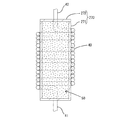
本実施例のノイズフィルタ10は、図1に示すように、コネクタ20、コンデンサ30、コイル40、磁性部材50、ケース60、及び保持部材70を備えている。ケース60は、コンデンサ30と、コイル40、磁性部材50、および保持部材70を収容している。なお、図1では、左側のコイル40、磁性部材50、および保持部材70を示しているが、ケース60内の右側にも同一の構成のコイル40、磁性部材50、および保持部材70が設けられている。ケース60は、例えば合成樹脂製である。ケース60は、ロアハウジング61、およびアッパハウジング(図示略)を備えている。ロアハウジング61は、例えば上方が開口する箱状である。アッパハウジングは、ロアハウジング61の上方の開口を閉塞可能な箱状である。ケース60は、後述する入出力用電線WHが挿通可能な一対の挿通孔62(一方のみ図1に表示)が形成されている。
As shown in FIG. 1, the
コネクタ20は、入出力用電線WHを構成するハーネス側導電路(図示略)に接続される。コネクタ20は、図1に示すように、筐体21、および端子金具22を備えている。端子金具22は、入出力用電線WH(本発明の「導線」に相当)の一端WH1が接続されている。入出力用電線WHの他端WH2は、はんだ付けによって導電板25に接続されている。筐体21は、箱状であり、入出力用電線WHが挿通する挿通孔(図示略)が形成されている。筐体21は、入出力用電線WHの他端WH2側を導出させた状態で、端子金具22を内部に収容している。なお、コネクタ20は、図1で左側の端子金具22のみが図示されているが、筐体21の右側にも同様の構成の端子金具22が収容されている。
The
コイル40は、図1に示すように、被覆されていない金属線材を巻回することで形成されている。コイル40は、一端41と他端42が互いに反対方向に向かうように所定の高さで引き出されている。コイル40の一端41は、はんだ付けによって導電板25に接続されている。コイル40の他端42は、はんだ付けによってコンデンサ30の一方の電極に接続されている。
As shown in FIG. 1, the
磁性部材50は、鉄などの磁性材料からなる粉末である。磁性部材50は、例えばフェライトや鉄の粉末である。磁性部材50は、コイル40を包囲してコイル40の周りに閉磁路を形成するように、保持部材70に保持されている。
The
保持部材70は、図1に示すように、外形が略直方体の箱状である。保持部材70は、磁性材料によって構成されている。保持部材70は、前箱部71、および後壁部72を備えている。前箱部71は、後方が開口した箱状である。後壁部72は、前箱部71の開口を閉塞するように前箱部71に組み付けられている。保持部材70は、ケース60の底面に固定されている。保持部材70は、前後方向で対向する一対の壁部の中心にそれぞれ挿通孔73,74が形成されている。保持部材70は、コイル40、および磁性部材50が内部に配置されている。挿通孔73は、コイル40の一端41が挿通している。挿通孔74は、コイル40の他端42が挿通している。挿通孔73,74は、保持部材70に対してコイル40を位置決めする手段としての機能を有する。コイル40は、左右方向および上下方向において、保持部材70の中心に位置している。磁性部材50は、コイル40と保持部材70の間に充填されている。具体的には、磁性部材50は、コイル40の内部、およびコイル40の外周と保持部材70との間に充填されている。このようにして、保持部材70は、磁性部材50をコイル40に対して位置決めした状態で保持している。コイル40、および磁性部材50は、保持部材70を介して位置決めされている。
As shown in FIG. 1, the holding
コンデンサ30は、例えばフィルムコンデンサである。コンデンサ30は、図1に示すように、コイル40と電気的に接続されている。具他的には、コンデンサ30は、左側の電極がコイル40の他端42に接続されている。なお、図1では、左側のコイル40のみを図示しているが、右側のコイル(図示略)の他端がコンデンサ30の右側の電極に接続されている。
The
以上のように構成されたノイズフィルタ10は、コネクタ20をハーネス側導電路(図示略)に接続することで、ハーネス側導電路に生じるノイズをコイル40、及びコンデンサ30によって除去することができる。その上で、コイル40は、磁性材料によって構成される保持部材70内において、磁性部材50によって包囲されている。そのため、ノイズフィルタ10は、コイル40から生じる磁束の漏れが抑制されて、コイル40のインダクタンスが向上する。このように、ノイズフィルタ10は、コイル40が収容された保持部材70内に磁性部材50を充填することで、ケース60の外観形状などを変えることなく、簡易な構成でノイズ除去性能を向上させることができる。
In the
次に、コイル40の保持部材70への組み付け工程について説明する。
まず、コンデンサ30、および保持部材70を、図1に示すように、ケース60の底面に取り付けられた状態にする。保持部材70は、前箱部71の開口を後壁部72によって閉塞されていない状態にする。そして、コイル40を、一端41側から開口を介して前箱部71の内部に入り込ませる。このとき、コイル40の一端41を挿通孔73に挿通させ、導電板25にはんだ付けする。その後、磁性部材50を保持部材70内に充填する。磁性部材50は、コイル40と保持部材70の間に充填される。具体的には、磁性部材50は、コイル40の内部、およびコイル40の外周と保持部材70との間に充填される。続いて、後壁部72の挿通孔74にコイル40の他端42を挿通させつつ、後壁部72によって前箱部71の開口を閉塞する。このとき、コイル40の他端42は、図1に示す仮想線(二点鎖線)のように、後方に延びた状態である。そのため、コイル40の他端42を折り曲げて、図1に示す実線のように、コンデンサ30の左側の電極に重なるようにする。そして、はんだ付けにより、コイル40の他端42とコンデンサ30の左側の電極を接続する。なお、右側のコイル(図示略)は、同様の工程によって保持部材70に組み付けられる。
Next, the step of assembling the
First, the
以上のように、本実施例1のノイズフィルタ10は、ノイズフィルタ10が、端子金具22に接続された入出力用電線WHに、コイル40、及びコンデンサ30が接続されている。そのため、ノイズフィルタ10は、入出力用電線WHに生じるノイズを、コイル40、及びコンデンサ30によって除去することができる。その上で、ノイズフィルタ10は、コイル40が収容されるケース60内において、磁性部材50が保持部材70により、コイル40に対して位置決めされている。そのため、コイル40から生じる磁束の漏れを抑制し、インダクタンスが低下することを抑制することができる。このように、ノイズフィルタ10は、磁性部材50を保持部材70に保持させる簡易な構成で、コイル40のノイズ除去性能を向上させることができる。
As described above, in the
また、ノイズフィルタ10は、保持部材70が、磁性材料からなっている。磁性部材50は、コイル40を包囲してコイル40の周りに閉磁路を形成するように、保持部材70に保持されている。
これにより、コイル40を包囲する磁性部材50によってコイル40の周りに閉磁路が形成される。そのため、ノイズフィルタ10は、コイル40から生じる磁束の漏れを抑制して、コイル40のインダクタンスを向上させることができる。
Further, in the
As a result, a closed magnetic path is formed around the
<実施例2>
次に、本発明を具体化した実施例2を、図2を参照して説明する。本実施例2のノイズフィルタ10は、保持部材の構成を上記実施例1とは異なる構成としたものである。その他の構成については上記実施例1と同じであるため、同じ構成については、同一符号を付し、構造、作用及び効果の説明は省略する。
<Example 2>
Next, Example 2 which embodies the present invention will be described with reference to FIG. The
保持部材270は、図2に示すように、両端が閉塞された円筒形状である容器状をなしている。保持部材270は、絶縁材料によって構成されている。保持部材270は、前箱部271、および後壁部272を備えている。前箱部271は、後方が開口した箱状である。後壁部272は、前箱部271の開口を閉塞するように前箱部271に組み付けられている。保持部材270は、ケース60の底面(図示略)に固定されている。保持部材270は、コイル40の内部に配置されている。具体的には、コイル40は、被覆されていない金属線材からなり、保持部材270の外周に巻き回され、保持部材270に対して位置決めされている。保持部材270は、外周面がコイル40の内周面に接触している。コイル40の一端41は、保持部材270の前側に延びている。コイル40の他端42は、保持部材270の後側に延びている。磁性部材50は、磁性材料の粉末からなり、保持部材270の内部に充填されるように収容されている。このようにして、保持部材270は、磁性部材50をコイル40に対して位置決めした状態で保持している。
As shown in FIG. 2, the holding
以上のように構成されたノイズフィルタ10は、実施例1のノイズフィルタ10と同様に、ハーネス側導電路に生じるノイズを除去するように機能する。その上で、ノイズフィルタ10は、コイル40の内部に磁性部材50が位置決めされた状態で配置されることで、コイル40のインダクタンスを高めることができる。また、磁性部材50は、絶縁材料からなる保持部材270に収容されるため、磁性部材50とコイル40とが直接的に接触することに起因する電食を防止することができる。このように、ノイズフィルタ10は、コイル40の内部に配置された保持部材270内に磁性部材50を充填することで、ケース60の外観形状などを変えることなく、簡易な構成でノイズ除去性能を向上させることができる。
The
次に、コイル40の保持部材270への組み付け工程について説明する。
コンデンサ30を、図1と同様に、ケース60の底面に取り付けられた状態に準備する。そして、保持部材270の外周に巻き回された状態のコイル40の一端41を、導電板25にはんだ付けする。続いて、保持部材270は、前箱部271の開口を後壁部272によって閉塞されていない状態にする。続いて、磁性部材50を保持部材270内に充填する。続いて、後壁部272で前箱部271の開口を閉塞する。その後、実施例1と同様にして、コイル40の他端42とコンデンサ30(図1参照)の左側の電極を接続する。なお、右側のコイル40は、同様の工程によって保持部材270に組み付けられる。
Next, the step of assembling the
The
本実施例2のノイズフィルタ10は、保持部材270が、容器状をなしていてコイル40の内部に配置されている。磁性部材50は、保持部材270に収容されている。
これにより、ノイズフィルタ10は、コイル40の内部に磁性部材50が配置されることで、インダクタンスを高めることができる。
In the
As a result, the
また、ノイズフィルタ10は、磁性部材50が絶縁材料からなる保持部材270に収容される。そのため、磁性部材50とコイル40とが直接的に接触することに起因する電食を防止することができる。
Further, in the
<実施例3>
次に、本発明を具体化した実施例3を、図3を参照して説明する。本実施例3のノイズフィルタ10は、ケースの内部の構成を上記実施例1とは異なる構成としたものである。その他の構成については上記実施例1と同じであるため、同じ構成については、同一符号を付し、構造、作用及び効果の説明は省略する。以下の説明において、前後の方向については、図3の下側を前側、上側を後側と定義する。左右の方向については、図3にあらわれる向きを、そのまま左方、右方と定義する。上下の方向については、図3の前側を上側、後側を下側と定義する。
<Example 3>
Next, Example 3 which embodies the present invention will be described with reference to FIG. The
実施例3のノイズフィルタ10は、図3に示すように、コネクタ(図示略)、一対のコンデンサ30、コイル40、磁性部材50、ケース360、保持部材70、およびアース部材80を備えている。ケース360は、箱状に形成されている。ケース360は、挿通孔363,364が形成されている。挿通孔363は、ケース360の前側の壁部において、左右方向の中央部分に、左右方向に長いスリット状に形成されている。挿通孔364は、ケース360の後側の壁部において、左右方向の中央部分に、挿通孔363よりも大きな孔として形成されている。
As shown in FIG. 3, the
アース部材80は、コンデンサ30と電気的に接続される接地用の部材である。アース部材80は、銅合金などの導電性板状部材を打ち抜いて曲げ加工を施すことで形成されている。アース部材80は、図3に示すように、アース板部81、取付部82、および受圧部83を備えている。アース板部81は、平面視四角形の平板状である。アース板部81は、ケース360の下面側に配置され、ケース360の下面の大部分を覆っている。アース板部81は、コイル40、及びコンデンサ30を支持している。取付部82は、ケース360より前方に向かって張り出している。取付部82は、ケース360の挿通孔363に後方から挿通されている。取付部82は、中央に真円状のボルト孔84が形成されている。ノイズフィルタ10は、ボルト孔84を介して図示しない車体パネル等にボルト締め固定される。受圧部83は、アース板部81の後側の縁部から上方へ略直角に立ち上がっている。受圧部83は、後方から押圧力が付与されることで、アース部材80がケース360に組み付けられている。
The grounding
一対のコンデンサ30、およびコイル40は、π型フィルタ回路を構成している。コイル40は、一端41が接続点P1で入出力用電線WHに接続されている。コイル40は、他端42が接続点P2で入出力用電線WHに接続されている。保持部材70は、アース板部81の上面において、受圧部83に対して前方に隣接して配置されている。磁性部材50は、磁性材料の粉末からなり、実施例1と同様に、保持部材70の内部に充填されている。一対のコンデンサ30は、例えば種類および容量が同じである。左側のコンデンサ30は、一方の電極がコイル40の一端41、および入出力用電線WHに接続点P1で接続されている。左側のコンデンサ30は、他方の電極が接続点P3でアース板部81に接続されている。右側のコンデンサ30は、一方の電極がコイル40の他端42、および入出力用電線WHに接続点P2で接続されている。右側のコンデンサ30は、他方の電極が接続点P4でアース板部81に接続されている。
The pair of
次に、アース部材80のケース360への組み付け工程について説明する。
入出力用電線WH、コンデンサ30、コイル40、および保持部材70を、図3に示すように、アース部材80に組み付けられた状態に準備する。そして、アース部材80を、ケース360の後方から挿通孔364を通過させてケース360の内部に組み付ける。このとき、アース部材80は、取付部82を先に向けて挿通孔364に挿入し、受圧部83には、後方から前向きの押圧力を付与する。すなわち、作業者は、受圧部83を、コイル40、及びコンデンサ30とは反対側から押す。そのため、作業者は、コイル40やコンデンサ30に触れる必要がないので、コイル40やコンデンサ30に破損を来す虞がない。取付部82は、ケース360の挿通孔363に挿入される。アース部材80は、例えばアース板部81がケース360の前側の壁部に接触した状態で固定される。このように、受圧部83を押圧するというワンアクションの動作だけで、コイル40とコンデンサ30とアース部材80をケース360に組み付けることができるので、作業性に優れている。
Next, the process of assembling the
The input / output electric wire WH, the
以上のように、本実施例3のノイズフィルタ10は、コンデンサ30と電気的に接続される接地用のアース部材80を備えている。アース部材80は、アース板部81、取付部82、および受圧部83を有している。アース板部81は、コイル40、及びコンデンサ30を支持する平板状である。取付部82は、アース板部81から延出し、接地部材に取り付けられて接地する。受圧部83は、アース板部81から立ち上がった形態であり、コイル40及びコンデンサ30とは反対側からの押圧力を受ける。アース部材80は、受圧部83に押圧力が付与されることで、ケース360に組み付けられている。
これにより、受圧部83を押圧するというワンアクションの動作だけで、コイル40とコンデンサ30とアース部材80をケース360に組み付けることができるので、作業性に優れている。しかも、ケース360に組み付ける際には、コイル40やコンデンサ30に触れる必要がないので、コイル40やコンデンサ30に破損を来す虞がない。
As described above, the
As a result, the
<実施例4>
次に、本発明を具体化した実施例4を、図4を参照して説明する。本実施例4のノイズフィルタ10は、磁性部材、および保持部材の構成を上記実施例1とは異なる構成としたものである。その他の構成については上記実施例1と同じであるため、同じ構成については、同一符号を付し、構造、作用及び効果の説明は省略する。以下の説明において、前後の方向については、図4にあらわれる向きを、そのまま前方、後方と定義する。左右の方向については、図4にあらわれる向きを、そのまま左方、右方と定義する。上下の方向については、図4にあらわれる向きを、そのまま上方、下方と定義する。
<Example 4>
Next, Example 4 which embodies the present invention will be described with reference to FIG. The
実施例4のノイズフィルタ10は、図4に示すように、コネクタ(図示略)、コンデンサ30、一対のコイル40、磁性部材450、及び保持部材470を備えている。コネクタ、コンデンサ30、およびコイル40は、実施例1と同様の構成である。コンデンサ30、およびコイル40は、ケース460に対して位置決めして取り付けられている。ケース460は、例えば合成樹脂製である。ケース460は、箱部461、および天井部462を備えている。箱部461は、上方が開口する箱状である。天井部462は、箱部461の上方の開口を閉塞可能な板状である。天井部462は、箱部461の開口に圧入されている。ケース460は、実施例1と同様に、入出力用電線WHが挿通可能な一対の挿通孔(図示略)が形成されている。
As shown in FIG. 4, the
保持部材470は、図4に示すように、ケース460の側壁の内面に固定して設けられている。具体的には、複数の保持部材470は、コイル40の周囲において、間隔を空けてコイル40を囲むように配置されている。図4では、保持部材470は、ケース460の各側壁に2つずつ設けられている。保持部材470は、天井部462と離れるように、ケース460の側壁における上下方向の中央に設けられている。保持部材470は、収容部471、および固定部472を備えている。収容部471は、方形状に凹む凹部473が形成されている。固定部472は、方形状である。固定部472は、ケース460の内面に取り付けられる部分である。保持部材470の凹部473は、ケース460の内面との間に隙間Sを空けて対向する形態である。保持部材470は、収容部471の凹部473が上方に開口するようにケース460の内面に設けられている。
As shown in FIG. 4, the holding
磁性部材450は、図4に示すように、薄板状である。磁性部材450は、保持部材470の上方から隙間Sに挿入されることで、保持部材470とケース460の内面とによって挟まれて保持されている。保持部材470に保持された磁性部材450は、コイル40、およびケース460に対して位置決めされる。保持部材470は、ケース460の側壁の内面に固定されているため、磁性部材450をケース460の内面に沿って配置することができる。磁性部材450は、隙間Sに挿入することで、容易に且つ位置決めされた状態でケース460に組み付けることができる。保持部材470は、ケース460の内面を利用することで、形状を簡素化することができる。複数の磁性部材450は、コイル40の周囲において、間隔を空けてコイル40を囲むように配置されている。磁性部材450は、ケース460の天井部462の下面に接触して、抜け止めされている。
As shown in FIG. 4, the
以上のように構成されたノイズフィルタ10は、複数の磁性部材450がコイル40を囲むように配置されているため、コイル40から生じる磁束の漏れを抑制し易く、コイル40のインダクタンスを向上させ易くなる。その上で、ノイズフィルタ10は、複数の磁性部材450が間隔を空けてコイル40の周囲に配置されているため、磁性部材450がコイル40の周囲全体に配置される構成と比べて、軽量化、及び低コスト化を図ることができる。
In the
以上のように、本実施例4のノイズフィルタ10は、磁性部材450が薄板状をなしている。保持部材470は、ケース460の内面との間に隙間Sを空けて対向する形態である。磁性部材450は、隙間Sに挿入されることで、保持部材470とケース460の内面とによって挟まれて保持されている。
これにより、磁性部材450は、保持部材470とケース460の内面との間の隙間Sに挿入することで、容易に且つ位置決めされた状態でケース460に組み付けることができる。磁性部材450を位置決めする手段として、ケース460の内面を利用したので、保持部材470だけで磁性部材450を位置決めする場合に比べると、保持部材470の形状を簡素化することができる。
As described above, in the
As a result, the
<他の実施例>
本発明は上記記述及び図面によって説明した実施例に限定されるものではなく、例えば次のような実施例も本発明の技術的範囲に含まれる。
(1)上記実施例1〜4では、コンデンサにフィルムコンデンサを用いたが、電解コンデンサやセラミックコンデンサであっても良い。
(2)上記実施例1〜4では、端子金具の極数を2としたが、3以上であっても構わない。
(3)上記実施例1〜4では、コンデンサとコイルとの接続にはんだ付けを用いたが、レーザ溶接や抵抗溶接等であっても良い。
(4)上記実施例3では、保持部材270の内部に、粉末状の磁性部材50が充填されていた。しかしながら、磁性部材50は、円柱状の固体であっても良い。
(5)上記実施例4では、保持部材470は、ケース460と別体であったが、一体であってもよい。
(6)上記実施例4では、保持部材470は、ケース460の各側面に2つずつ配置されていたが、2つ以外の数で配置されてもよい。
<Other Examples>
The present invention is not limited to the examples described by the above description and drawings, and for example, the following examples are also included in the technical scope of the present invention.
(1) In Examples 1 to 4 above, a film capacitor is used as the capacitor, but an electrolytic capacitor or a ceramic capacitor may be used.
(2) In the above Examples 1 to 4, the number of poles of the terminal fitting is set to 2, but it may be 3 or more.
(3) In Examples 1 to 4 above, soldering is used for connecting the capacitor and the coil, but laser welding, resistance welding, or the like may be used.
(4) In Example 3 above, the inside of the holding
(5) In the fourth embodiment, the holding
(6) In the fourth embodiment, two holding
10…ノイズフィルタ
20…コネクタ
22…端子金具
30…コンデンサ
40…コイル
50,450…磁性部材
60,360,460…ケース
70,270,470…保持部材
80…アース部材
81…アース板部
82…取付部
83…受圧部
S…隙間
WH…入出力用電線(導線)
10 ...
Claims (5)
前記導線に接続されたコイルと、
前記コイルと電気的に接続されたコンデンサと、
磁性部材と、
前記コンデンサ、前記コイル、及び前記磁性部材を収容するケースと、
前記磁性部材を前記コイルに対して位置決めした状態で保持する保持部材と、
を備え、
前記保持部材は、磁性材料からなり、
前記磁性部材は、前記コイルを包囲して前記コイルの周りに閉磁路を形成するように、前記保持部材に保持されており、
複数の前記磁性部材が、前記コイルの周囲において、間隔を空けて前記コイルを囲むように配置されていることを特徴とするノイズフィルタ。 A connector that accommodates the terminal fitting to which the conducting wire is connected in a state where the conducting wire is led out, and
With the coil connected to the conductor
A capacitor electrically connected to the coil and
With magnetic members
A case for accommodating the capacitor, the coil, and the magnetic member,
A holding member that holds the magnetic member in a positioned state with respect to the coil, and
With
The holding member is made of a magnetic material and is made of a magnetic material.
The magnetic member is held by the holding member so as to surround the coil and form a closed magnetic path around the coil.
A noise filter characterized in that a plurality of the magnetic members are arranged around the coil so as to surround the coil at intervals.
前記導線に接続されたコイルと、
前記コイルと電気的に接続されたコンデンサと、
磁性部材と、
前記コンデンサ、前記コイル、及び前記磁性部材を収容するケースと、
前記磁性部材を前記コイルに対して位置決めした状態で保持する保持部材と、
を備え、
前記保持部材は、磁性材料からなり、
前記磁性部材は、前記コイルを包囲して前記コイルの周りに閉磁路を形成するように、前記保持部材に保持されており、
前記保持部材は、前記ケースの内面に固定して設けられており、
前記磁性部材は薄板状をなしており、
前記保持部材は、前記ケースの内面との間に隙間を空けて対向する形態であり、
前記磁性部材は、前記隙間に挿入されることで、前記保持部材と前記ケースの内面とによって挟まれて保持されていることを特徴とするノイズフィルタ。 A connector that accommodates the terminal fitting to which the conducting wire is connected in a state where the conducting wire is led out, and
With the coil connected to the conductor
A capacitor electrically connected to the coil and
With magnetic members
A case for accommodating the capacitor, the coil, and the magnetic member,
A holding member that holds the magnetic member in a positioned state with respect to the coil, and
With
The holding member is made of a magnetic material and is made of a magnetic material.
The magnetic member is held by the holding member so as to surround the coil and form a closed magnetic path around the coil.
The holding member is fixedly provided on the inner surface of the case.
The magnetic member has a thin plate shape and has a thin plate shape.
The holding member has a form of facing the inner surface of the case with a gap.
A noise filter characterized in that the magnetic member is inserted into the gap and is sandwiched and held by the holding member and the inner surface of the case.
前記導線に接続されたコイルと、
前記コイルと電気的に接続されたコンデンサと、
磁性部材と、
前記コンデンサ、前記コイル、及び前記磁性部材を収容するケースと、
前記磁性部材を前記コイルに対して位置決めした状態で保持する保持部材と、
前記コンデンサと電気的に接続される接地用のアース部材と、
を備え、
前記アース部材は、
前記コイル、及び前記コンデンサを支持する平板状のアース板部と、
前記アース板部から延出し、接地部材に取り付けられて接地する取付部と、
前記アース板部から立ち上がった形態であり、前記コイル及び前記コンデンサとは反対側からの押圧力を受ける受圧部と、
を有し、前記受圧部に押圧力が付与されることで前記アース部材が前記ケースに組み付けられていることを特徴とするノイズフィルタ。 A connector that accommodates the terminal fitting to which the conducting wire is connected in a state where the conducting wire is led out, and
With the coil connected to the conductor
A capacitor electrically connected to the coil and
With magnetic members
A case for accommodating the capacitor, the coil, and the magnetic member,
A holding member that holds the magnetic member in a positioned state with respect to the coil, and
A grounding member that is electrically connected to the capacitor and
With
The ground member
A flat plate-shaped ground plate that supports the coil and the capacitor,
An attachment part that extends from the earth plate part and is attached to the grounding member to be grounded.
A pressure receiving portion that rises from the ground plate portion and receives a pressing force from the side opposite to the coil and the capacitor.
The noise filter is characterized in that the grounding member is assembled to the case by applying a pressing force to the pressure receiving portion.
前記導線に接続されたコイルと、
前記コイルと電気的に接続されたコンデンサと、
磁性部材と、
前記コンデンサ、前記コイル、及び前記磁性部材を収容するケースと、
前記磁性部材を前記コイルに対して位置決めした状態で保持する保持部材と、
を備え、
前記磁性部材は、磁性材料からなる粉末であり、前記保持部材内に充填されており、
前記磁性部材は、前記コイルを包囲して前記コイルの周りに閉磁路を形成するように、前記保持部材に保持されていることを特徴とするノイズフィルタ。 A connector that accommodates the terminal fitting to which the conducting wire is connected in a state where the conducting wire is led out, and
With the coil connected to the conductor
A capacitor electrically connected to the coil and
With magnetic members
A case for accommodating the capacitor, the coil, and the magnetic member,
A holding member that holds the magnetic member in a positioned state with respect to the coil, and
With
The magnetic member is a powder made of a magnetic material, and is filled in the holding member .
The noise filter is characterized in that the magnetic member is held by the holding member so as to surround the coil and form a closed magnetic path around the coil.
Priority Applications (4)
| Application Number | Priority Date | Filing Date | Title |
|---|---|---|---|
| JP2018094475A JP6950620B2 (en) | 2018-05-16 | 2018-05-16 | Noise filter |
| CN201980030057.7A CN112075023A (en) | 2018-05-16 | 2019-04-25 | Noise filter |
| US17/053,489 US11264965B2 (en) | 2018-05-16 | 2019-04-25 | Noise filter |
| PCT/JP2019/017567 WO2019220911A1 (en) | 2018-05-16 | 2019-04-25 | Noise filter |
Applications Claiming Priority (1)
| Application Number | Priority Date | Filing Date | Title |
|---|---|---|---|
| JP2018094475A JP6950620B2 (en) | 2018-05-16 | 2018-05-16 | Noise filter |
Publications (3)
| Publication Number | Publication Date |
|---|---|
| JP2019201317A JP2019201317A (en) | 2019-11-21 |
| JP2019201317A5 JP2019201317A5 (en) | 2020-10-22 |
| JP6950620B2 true JP6950620B2 (en) | 2021-10-13 |
Family
ID=68540277
Family Applications (1)
| Application Number | Title | Priority Date | Filing Date |
|---|---|---|---|
| JP2018094475A Active JP6950620B2 (en) | 2018-05-16 | 2018-05-16 | Noise filter |
Country Status (4)
| Country | Link |
|---|---|
| US (1) | US11264965B2 (en) |
| JP (1) | JP6950620B2 (en) |
| CN (1) | CN112075023A (en) |
| WO (1) | WO2019220911A1 (en) |
Families Citing this family (2)
| Publication number | Priority date | Publication date | Assignee | Title |
|---|---|---|---|---|
| US11844178B2 (en) * | 2020-06-02 | 2023-12-12 | Analog Devices International Unlimited Company | Electronic component |
| JP2023083848A (en) * | 2021-12-06 | 2023-06-16 | 日本ピラー工業株式会社 | Oil condition detection apparatus |
Family Cites Families (8)
| Publication number | Priority date | Publication date | Assignee | Title |
|---|---|---|---|---|
| JPS60144316U (en) * | 1984-03-03 | 1985-09-25 | 株式会社トーキン | noise filter device |
| JP2585303Y2 (en) * | 1992-07-24 | 1998-11-18 | 株式会社トーキン | Noise prevention choke coil |
| JP2006041803A (en) * | 2004-07-26 | 2006-02-09 | Shigehiro Makino | Noise filter |
| JP2007335277A (en) * | 2006-06-16 | 2007-12-27 | Murata Mfg Co Ltd | Noise eliminator |
| JP6152722B2 (en) * | 2013-07-08 | 2017-06-28 | 株式会社オートネットワーク技術研究所 | Noise filter device |
| JP2016063331A (en) * | 2014-09-17 | 2016-04-25 | Necトーキン株式会社 | Resonator, electronic pen, and method of manufacturing resonator |
| JP6822759B2 (en) | 2015-04-27 | 2021-01-27 | 矢崎総業株式会社 | Noise filter and wire harness |
| DE112017001684T5 (en) * | 2016-03-31 | 2018-12-13 | Kabushiki Kaisha Toyota Jidoshokki | Vehicle-side electric compressor |
-
2018
- 2018-05-16 JP JP2018094475A patent/JP6950620B2/en active Active
-
2019
- 2019-04-25 CN CN201980030057.7A patent/CN112075023A/en active Pending
- 2019-04-25 WO PCT/JP2019/017567 patent/WO2019220911A1/en active Application Filing
- 2019-04-25 US US17/053,489 patent/US11264965B2/en active Active
Also Published As
| Publication number | Publication date |
|---|---|
| US20210143786A1 (en) | 2021-05-13 |
| JP2019201317A (en) | 2019-11-21 |
| CN112075023A (en) | 2020-12-11 |
| US11264965B2 (en) | 2022-03-01 |
| WO2019220911A1 (en) | 2019-11-21 |
Similar Documents
| Publication | Publication Date | Title |
|---|---|---|
| JP6152722B2 (en) | Noise filter device | |
| JP6152739B2 (en) | Noise filter device | |
| CN108605420A (en) | circuit structure and electric connection box | |
| JP6950620B2 (en) | Noise filter | |
| CN102412474A (en) | Cable connector component | |
| JP2018186242A (en) | Coil component and electronic device | |
| JP6375681B2 (en) | Filter element built-in connector | |
| JP2001203490A (en) | Filter device for at least one elastic wiring connected externally to case | |
| JP7213408B2 (en) | capacitor | |
| JP4465699B2 (en) | Noise filter | |
| JP7207030B2 (en) | Electronic component and its manufacturing method | |
| US20170084391A1 (en) | Connection structure for electrical component assembly, hydraulic pressure control apparatus, and method for producing electrically conductive member | |
| JP6996483B2 (en) | Circuit configuration | |
| JP7384862B2 (en) | Shield member and shield connector | |
| JP7349679B2 (en) | capacitor | |
| JP4927344B2 (en) | State determination device | |
| JP5950208B2 (en) | Joint connector with built-in noise filter | |
| JP3206553U (en) | Electronic device package case | |
| WO2018180484A1 (en) | Connector | |
| JP2015088248A (en) | Filter element built-in type connector | |
| EP2955800B1 (en) | Joint connector with internal noise filter | |
| JP2019009537A (en) | Noise filter | |
| JP2015088249A (en) | Filter element built-in type connector | |
| JP2020010122A (en) | Noise filter and wire harness | |
| JP2015088305A (en) | Filter element built-in type connector |
Legal Events
| Date | Code | Title | Description |
|---|---|---|---|
| A621 | Written request for application examination |
Free format text: JAPANESE INTERMEDIATE CODE: A621 Effective date: 20200827 |
|
| A521 | Written amendment |
Free format text: JAPANESE INTERMEDIATE CODE: A523 Effective date: 20200909 |
|
| A131 | Notification of reasons for refusal |
Free format text: JAPANESE INTERMEDIATE CODE: A131 Effective date: 20201029 |
|
| A521 | Written amendment |
Free format text: JAPANESE INTERMEDIATE CODE: A523 Effective date: 20201210 |
|
| A131 | Notification of reasons for refusal |
Free format text: JAPANESE INTERMEDIATE CODE: A131 Effective date: 20210304 |
|
| A521 | Written amendment |
Free format text: JAPANESE INTERMEDIATE CODE: A523 Effective date: 20210408 |
|
| TRDD | Decision of grant or rejection written | ||
| A01 | Written decision to grant a patent or to grant a registration (utility model) |
Free format text: JAPANESE INTERMEDIATE CODE: A01 Effective date: 20210824 |
|
| A61 | First payment of annual fees (during grant procedure) |
Free format text: JAPANESE INTERMEDIATE CODE: A61 Effective date: 20210906 |
|
| R150 | Certificate of patent or registration of utility model |
Ref document number: 6950620 Country of ref document: JP Free format text: JAPANESE INTERMEDIATE CODE: R150 |