JP6949963B2 - Terminals, wireless communication methods and systems - Google Patents
Terminals, wireless communication methods and systems Download PDFInfo
- Publication number
- JP6949963B2 JP6949963B2 JP2019533803A JP2019533803A JP6949963B2 JP 6949963 B2 JP6949963 B2 JP 6949963B2 JP 2019533803 A JP2019533803 A JP 2019533803A JP 2019533803 A JP2019533803 A JP 2019533803A JP 6949963 B2 JP6949963 B2 JP 6949963B2
- Authority
- JP
- Japan
- Prior art keywords
- bwp
- resource
- unit
- information
- transmission
- Prior art date
- Legal status (The legal status is an assumption and is not a legal conclusion. Google has not performed a legal analysis and makes no representation as to the accuracy of the status listed.)
- Active
Links
Images


Classifications
-
- H—ELECTRICITY
- H04—ELECTRIC COMMUNICATION TECHNIQUE
- H04L—TRANSMISSION OF DIGITAL INFORMATION, e.g. TELEGRAPHIC COMMUNICATION
- H04L5/00—Arrangements affording multiple use of the transmission path
- H04L5/0001—Arrangements for dividing the transmission path
- H04L5/0003—Two-dimensional division
- H04L5/0005—Time-frequency
- H04L5/0007—Time-frequency the frequencies being orthogonal, e.g. OFDM(A), DMT
- H04L5/001—Time-frequency the frequencies being orthogonal, e.g. OFDM(A), DMT the frequencies being arranged in component carriers
-
- H—ELECTRICITY
- H04—ELECTRIC COMMUNICATION TECHNIQUE
- H04W—WIRELESS COMMUNICATION NETWORKS
- H04W72/00—Local resource management
- H04W72/04—Wireless resource allocation
- H04W72/044—Wireless resource allocation based on the type of the allocated resource
- H04W72/0446—Resources in time domain, e.g. slots or frames
-
- H—ELECTRICITY
- H04—ELECTRIC COMMUNICATION TECHNIQUE
- H04L—TRANSMISSION OF DIGITAL INFORMATION, e.g. TELEGRAPHIC COMMUNICATION
- H04L5/00—Arrangements affording multiple use of the transmission path
- H04L5/003—Arrangements for allocating sub-channels of the transmission path
- H04L5/0044—Arrangements for allocating sub-channels of the transmission path allocation of payload
-
- H—ELECTRICITY
- H04—ELECTRIC COMMUNICATION TECHNIQUE
- H04L—TRANSMISSION OF DIGITAL INFORMATION, e.g. TELEGRAPHIC COMMUNICATION
- H04L5/00—Arrangements affording multiple use of the transmission path
- H04L5/0091—Signaling for the administration of the divided path
- H04L5/0094—Indication of how sub-channels of the path are allocated
-
- H—ELECTRICITY
- H04—ELECTRIC COMMUNICATION TECHNIQUE
- H04W—WIRELESS COMMUNICATION NETWORKS
- H04W28/00—Network traffic management; Network resource management
- H04W28/16—Central resource management; Negotiation of resources or communication parameters, e.g. negotiating bandwidth or QoS [Quality of Service]
- H04W28/26—Resource reservation
-
- H—ELECTRICITY
- H04—ELECTRIC COMMUNICATION TECHNIQUE
- H04W—WIRELESS COMMUNICATION NETWORKS
- H04W72/00—Local resource management
- H04W72/04—Wireless resource allocation
- H04W72/044—Wireless resource allocation based on the type of the allocated resource
- H04W72/0453—Resources in frequency domain, e.g. a carrier in FDMA
-
- H—ELECTRICITY
- H04—ELECTRIC COMMUNICATION TECHNIQUE
- H04W—WIRELESS COMMUNICATION NETWORKS
- H04W72/00—Local resource management
- H04W72/20—Control channels or signalling for resource management
- H04W72/23—Control channels or signalling for resource management in the downlink direction of a wireless link, i.e. towards a terminal
Description
本開示は、次世代移動通信システムにおける端末、無線通信方法及びシステムに関する。 The present disclosure relates to terminals, wireless communication methods and systems in next-generation mobile communication systems.
UMTS(Universal Mobile Telecommunications System)ネットワークにおいて、さらなる高速データレート、低遅延などを目的としてロングタームエボリューション(LTE:Long Term Evolution)が仕様化された(非特許文献1)。また、LTEからの更なる広帯域化及び高速化を目的として、LTEの後継システム(例えば、LTE−A(LTE-Advanced)、FRA(Future Radio Access)、4G、5G、5G+(plus)、NR(New RAT)、LTE Rel.14、15〜、などともいう)も検討されている。 In the UMTS (Universal Mobile Telecommunications System) network, Long Term Evolution (LTE) has been specified for the purpose of higher data rate, lower latency, etc. (Non-Patent Document 1). In addition, for the purpose of further widening and speeding up from LTE, successor systems of LTE (for example, LTE-A (LTE-Advanced), FRA (Future Radio Access), 4G, 5G, 5G + (plus), NR ( New RAT), LTE Rel.14, 15-5, etc.) are also being considered.
また、既存のLTEシステム(例えば、LTE Rel.8−13)では、1msのサブフレームをスケジューリング単位として、下りリンク(DL:Downlink)及び/又は上りリンク(UL:Uplink)の通信が行われる。当該サブフレームは、例えば、通常サイクリックプレフィックスの場合、サブキャリア間隔15kHzの14シンボルで構成される。当該サブフレームは、伝送時間間隔(TTI:Transmission Time Interval)等とも呼ばれる。 Further, in an existing LTE system (for example, LTE Rel. 8-13), downlink (DL: Downlink) and / or uplink (UL: Uplink) communication is performed with a 1 ms subframe as a scheduling unit. The subframe is composed of 14 symbols with a subcarrier spacing of 15 kHz, for example, in the case of a normal cyclic prefix. The subframe is also referred to as a transmission time interval (TTI) or the like.
将来の無線通信システム(例えば、NR)においては、コンポーネントキャリア(CC:Component Carrier)又はシステム帯域幅に含まれる1つ又は複数の帯域幅部分(BWP:Bandwidth part)を、ユーザ端末(UE:User Equipment)に対して設定することが検討されている。DL通信に利用されるBWPは、DL BWPと呼ばれてもよく、UL通信に利用されるBWPは、UL BWPと呼ばれてもよい。 In a future wireless communication system (for example, NR), one or more bandwidth parts (BWP: Bandwidth part) included in a component carrier (CC: Component Carrier) or a system bandwidth may be used as a user terminal (UE: User). Equipment) is being considered for setting. The BWP used for DL communication may be called DL BWP, and the BWP used for UL communication may be called UL BWP.
NRにおいては、データチャネルのスケジューリング単位となる時間単位(例えば、スロット及び/又はミニスロット)内の所定の時間/周波数リソースを将来的な拡張性のために確保できるようにすることが検討されている。当該所定の時間/周波数リソースは、unknownリソース、確保(reserved)リソース、ブランクリソース又は未使用(unused)リソースなどと呼ばれてもよい。 In NR, it is considered to be able to secure a predetermined time / frequency resource in a time unit (for example, a slot and / or a mini slot) which is a scheduling unit of a data channel for future expandability. There is. The predetermined time / frequency resource may be referred to as an unknown resource, a reserved resource, a blank resource, an unused resource, or the like.
NRにおいてはBWPに基づく制御が利用されると考えられる。しかしながら、BWPが導入される場合において、UEがどのようにブランクリソースを把握するかについてはまだ検討が進んでいない。ブランクリソースの適切な判断方法を導入しなければ、柔軟な制御ができず、通信スループット、周波数利用効率などの劣化が生じるおそれがある。 It is considered that BWP-based control is used in NR. However, when BWP is introduced, how the UE grasps the blank resource has not been studied yet. Unless an appropriate method for determining blank resources is introduced, flexible control cannot be performed, and there is a risk that communication throughput, frequency utilization efficiency, etc. will deteriorate.
そこで、本開示は、BWPに基づく制御を行う場合であっても、通信スループットの低下などを抑制できる端末、無線通信方法及びシステムを提供することを目的の1つとする。
Therefore, one of the purposes of the present disclosure is to provide a terminal, a wireless communication method, and a system that can suppress a decrease in communication throughput even when controlling based on BWP.
本発明の一態様にかかる端末は、帯域幅部分(Bandwidth part(BWP))固有のリザーブドリソースに関する第1の設定情報及びセル固有のリザーブドリソースに関する第2の設定情報の少なくとも一方を受信する受信部と、前記第1の設定情報及び前記第2の設定情報の少なくとも一方に対応するリザーブドリソースにおいてPhysical Downlink Shared Channel(PDSCH)の割当てがないと想定し、前記PDSCHの受信処理を制御する制御部と、を有する。 End end that written to an aspect of the present invention, the The bandwidth portion (B andwidth part (BWP)) second setting information related to the first setting information and cell specific reserved resources for specific reserved resource Assuming that the Physical Downlink Shared Channel (PDSCH) is not allocated in the receiving unit that receives at least one and the reserved resource corresponding to at least one of the first setting information and the second setting information, the PDSCH and a control unit that controls the reception process, that have a.
本開示の一態様によれば、BWPに基づく制御を行う場合であっても、通信スループットの低下などを抑制できる。 According to one aspect of the present disclosure, even in the case of performing control based on BWP, it is possible to suppress a decrease in communication throughput and the like.
将来の無線通信システム(例えば、NR、5G及び5G+の少なくとも1つなど。以下、単にNRともいう)では、データチャネルのスケジューリング単位として、既存のLTEシステム(例えば、LTE Rel.8−13)のサブフレームとは異なる時間単位(例えば、スロット及び/又はミニスロット及び/又は1つ又は複数のOFDMシンボルなど)を利用することが検討されている。 In future wireless communication systems (eg, at least one of NR, 5G and 5G +; hereinafter simply referred to as NR), as a data channel scheduling unit, an existing LTE system (eg, LTE Rel. 8-13) It is being considered to use different time units than subframes (eg, slots and / or mini-slots and / or one or more OFDM symbols).
なお、データチャネルは、DLデータチャネル(例えば、下り共有チャネル(PDSCH:Physical Downlink Shared Channel))、ULデータチャネル(例えば、上り共有チャネル(PUSCH:Physical Uplink Shared Channel))などであってもよく、単に、データ又は共有チャネルなどと呼ばれてもよい。 The data channel may be a DL data channel (for example, a downlink shared channel (PDSCH: Physical Downlink Shared Channel)), a UL data channel (for example, an uplink shared channel (PUSCH: Physical Uplink Shared Channel)), or the like. It may be simply referred to as a data or shared channel.
ここで、スロットは、UEが適用するニューメロロジー(例えば、サブキャリア間隔及び/又はシンボル長)に基づく時間単位である。1スロットあたりのシンボル数は、サブキャリア間隔に応じて定められてもよい。例えば、サブキャリア間隔が15kHz又は30kHzである場合、当該1スロットあたりのシンボル数は、7又は14シンボルであってもよい。一方、サブキャリア間隔が60kHz以上の場合、1スロットあたりのシンボル数は、14シンボルであってもよい。ミニスロットは、スロットよりも短い時間長(又は少ないシンボル数)を有する時間単位である。 Here, a slot is a time unit based on the numerology applied by the UE (eg, subcarrier spacing and / or symbol length). The number of symbols per slot may be determined according to the subcarrier interval. For example, when the subcarrier interval is 15 kHz or 30 kHz, the number of symbols per slot may be 7 or 14 symbols. On the other hand, when the subcarrier interval is 60 kHz or more, the number of symbols per slot may be 14 symbols. A minislot is a time unit that has a shorter time length (or fewer symbols) than a slot.
NRでは、DL制御チャネル(例えば、PDCCH(Physical Downlink Control Channel))とDLデータチャネル(例えば、PDSCH)との間でリソースを共用すること(リソース共用(resource sharing)などと呼ばれてもよい)が検討されている。図1は、DL制御チャネルとDLデータチャネルとのリソース共用の一例を示す図である。 In NR, sharing resources between a DL control channel (for example, PDCCH (Physical Downlink Control Channel)) and a DL data channel (for example, PDSCH) (may be called resource sharing). Is being considered. FIG. 1 is a diagram showing an example of resource sharing between a DL control channel and a DL data channel.
図1に示すように、所定の(given)時間及び/又は周波数リソース(時間/周波数リソース)がDL制御チャネル用に確保(reserve)され、当該所定の時間及び/又は周波数リソースの少なくとも一部にDL制御チャネルが割り当てられる。 As shown in FIG. 1, a given time and / or frequency resource (time / frequency resource) is reserved for the DL control channel and is at least a portion of the predetermined time and / or frequency resource. A DL control channel is assigned.
すなわち、当該所定の時間及び/又は周波数リソースは、1つ又は複数のDL制御チャネルが割り当てられる候補領域を含んでもよく、当該候補領域は制御リソースセット(CORESET:control resource set)、コントロールサブバンド(control subband)、サーチスペースセット、サーチスペースリソースセット、制御領域、制御サブバンド又はNR−PDCCH領域などと呼ばれてもよい。 That is, the predetermined time and / or frequency resource may include a candidate area to which one or more DL control channels are assigned, and the candidate area includes a control resource set (CORESET) and a control subband (control resource set). It may be called a control subband), a search space set, a search space resource set, a control area, a control subband, an NR-PDCCH area, or the like.
所定の時間及び/又は周波数リソースは、確保(reserved)リソースなどと呼ばれてもよい。確保リソースの構成(パターン又は確保リソースパターン等ともいう)は、例えばスロットにスケジュールされるUE数、UE能力(capability)などによって変動する。確保リソースは、所定の時間単位において1つ又は複数のUEによって利用され得るCORESET全体の領域に相当してもよい。 Predetermined time and / or frequency resources may be referred to as reserved resources and the like. The configuration of the reserved resource (also referred to as a pattern or the reserved resource pattern, etc.) varies depending on, for example, the number of UEs scheduled in the slot, the UE capability, and the like. The reserved resource may correspond to the entire area of CORESET that can be utilized by one or more UEs in a predetermined time unit.
図1に示すように、UEには、複数の確保リソースパターン(ここでは、パターン0〜3)が準静的に(上位レイヤシグナリング(例えば、RRC(Radio Resource Control)シグナリング、ブロードキャスト情報(マスタ情報ブロック(MIB:Master Information Block)、システム情報ブロック(SIB:System Information Block)など)によって)設定されてもよい。 As shown in FIG. 1, a plurality of reserved resource patterns (here, patterns 0 to 3) are quasi-statically (upper layer signaling (for example, RRC (Radio Resource Control) signaling, broadcast information (master information)) in the UE. It may be set by a block (MIB: Master Information Block), a system information block (SIB: System Information Block), etc.).
UEは、CORESETの設定情報(CORESET設定と呼ばれてもよい)を、基地局(例えば、BS(Base Station)、送受信ポイント(TRP:Transmission/Reception Point)、eNB(eNode B)、gNBなどと呼ばれてもよい)から受信してもよい。CORESET設定は、例えば、上位レイヤシグナリング(例えば、RRCシグナリング及び/又はSIB)によって通知されてもよい。 The UE transmits the CORESET setting information (which may be referred to as CORESET setting) to a base station (for example, BS (Base Station), transmission / reception point (TRP: Transmission / Reception Point), eNB (eNode B), gNB, etc.). May be called). The CORESET setting may be notified, for example, by higher layer signaling (eg, RRC signaling and / or SIB).
UEは、自端末に設定された1つ又は複数のCORESET(又は当該CORESET内のサーチスペース)をモニタ(ブラインド復号)して、当該UEに対するDL制御チャネル(下りリンク制御情報(DCI:Downlink Control Information))を検出する。 The UE monitors (blindly decodes) one or more CORESETs (or search spaces in the CORESETs) set in the own terminal, and performs a DL control channel (downlink control information (DCI)) for the UE. )) Is detected.
UEには、複数の確保リソースパターンの中から、あるスロットで用いられる確保リソースパターンを、所定のDCIによって動的に指示されてもよい。当該所定のDCIは、1つ以上のUEに共通のPDCCH(グループ共通PDCCH、グループ共通DCIなどと呼ばれてもよい)を用いて通知されてもよいし、UE固有のPDCCH(スケジューリング用のDCIなどと呼ばれてもよい)を用いて通知されてもよいし、PDCCHとは異なる下り制御チャネルによって通知されてもよい。 The UE may dynamically instruct the reserved resource pattern used in a certain slot from a plurality of reserved resource patterns by a predetermined DCI. The predetermined DCI may be notified using a PDCCH common to one or more UEs (may be called a group common PDCCH, a group common DCI, etc.), or a UE-specific PDCCH (DCI for scheduling). It may be notified by using a downlink control channel different from PDCCH.
なお、DLデータ(例えば、PDSCH)受信及び/又はDL参照信号の測定をスケジューリングするDCIは、DLアサインメント、DLグラント、DL DCIなどと呼ばれてもよい。ULデータ(例えば、PUSCH)送信及び/又はULサウンディング(測定用)信号の送信をスケジューリングするDCIは、ULグラント、UL DCIなどと呼ばれてもよい。 The DCI that schedules the reception of DL data (for example, PDSCH) and / or the measurement of the DL reference signal may be referred to as DL assignment, DL grant, DL DCI, or the like. The DCI that schedules the transmission of UL data (eg, PUSCH) and / or the transmission of UL sounding (measurement) signals may be referred to as UL grants, UL DCIs, and the like.
UEは、動的に指示される確保リソースパターンと、DLアサインメントとに基づいて、DLデータチャネルの受信処理(復号など)を行ってもよい。UEは、動的に指示される確保リソースパターンと、ULグラントとに基づいて、ULデータチャネルの送信処理(符号化など)を行ってもよい。 The UE may perform reception processing (decoding, etc.) of the DL data channel based on the dynamically instructed reserved resource pattern and the DL assignment. The UE may perform transmission processing (encoding, etc.) of the UL data channel based on the dynamically instructed reserved resource pattern and the UL grant.
なお、図1におけるNRキャリア帯域とは、UEに割り当てられるコンポーネントキャリア(CC:Component Carrier)(例えば、200MHz、システム帯域等ともいう)であってもよいし、又は、当該CCの少なくとも一部である帯域幅部分(BWP:Bandwidth part)であってもよい。UEには一以上のBWPが設定される。 The NR carrier band in FIG. 1 may be a component carrier (CC: Component Carrier) (for example, 200 MHz, also referred to as a system band) assigned to the UE, or at least a part of the CC. It may be a certain bandwidth part (BWP: Bandwidth part). One or more BWPs are set in the UE.
UEに設定される各BWPの構成(configuration)情報は、各BWPのニューメロロジー、周波数位置(例えば、中心周波数)、帯域幅(例えば、リソースブロック(RB(Resource Block)、PRB(Physical RB)などとも呼ばれる)の数)、時間リソース(例えば、スロット(ミニスロット)インデックス、周期)などの少なくとも一つを示す情報を含んでもよい。当該構成情報は、上位レイヤシグナリング又はMAC(Medium Access Control)シグナリング)によってUEに通知されてもよい。 The configuration information of each BWP set in the UE includes the numerology of each BWP, the frequency position (for example, the center frequency), and the bandwidth (for example, the resource block (RB (Resource Block), PRB (Physical RB)). It may also contain information indicating at least one such as number), time resources (eg, slot (minislot) index, period). The configuration information may be notified to the UE by higher layer signaling or MAC (Medium Access Control) signaling.
NRは、初期導入(例えば、5G、LTE Rel.15以降又はフェーズ1)及び初期導入された仕様に対する継続的な進化(例えば、5G+、LTE Rel.16以降又はフェーズ2)などのように、段階的な標準化が行われることが想定される。したがって、将来的な拡張性(フォワードコンパチビリティ)を考慮して、データチャネルのスケジューリング単位となる時間単位(例えば、スロット及び/又はミニスロット)を構成することが望まれる。 NR is staged, such as initial introduction (eg, 5G, LTE Rel.15 or later or Phase 1) and continuous evolution to the initially introduced specifications (eg, 5G +, LTE Rel.16 or later or Phase 2). Standardization is expected to take place. Therefore, in consideration of future expandability (forward compatibility), it is desirable to configure a time unit (for example, a slot and / or a mini slot) which is a scheduling unit of a data channel.
そこで、データチャネルのスケジューリング単位となる時間単位(例えば、スロット及び/又はミニスロット)内の所定の時間/周波数リソースをフォワードコンパチビリティ用に確保しておくことが検討されている。当該所定の時間/周波数リソースは、アンノウン(unknown)リソース、リザーブド(確保、予約(reserved))リソース、ブランク(blank)リソース又は未使用(unused)リソース等とも呼ばれる。ブランクリソースは、図1において説明した確保リソースとして設定されてもよい(確保リソースと少なくとも一部が重複してもよい)し、当該確保リソースとは別に設定されてもよい。 Therefore, it is considered to reserve a predetermined time / frequency resource in a time unit (for example, a slot and / or a mini slot) which is a scheduling unit of a data channel for forward compatibility. The predetermined time / frequency resource is also referred to as an unknown resource, a reserved resource, a blank resource, an unused resource, or the like. The blank resource may be set as the reserved resource described in FIG. 1 (at least a part of the reserved resource may overlap), or may be set separately from the reserved resource.
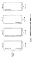
図2は、ブランクリソースの一例を示す図である。図2に示すように、ブランクリソースは、スロット内の少なくとも一部のシンボル及び/又はキャリア(又はBWP)内の少なくとも一部のPRBで構成されてもよい。UEは、当該ブランクリソースに関して、送受信制御及び/又は動作を想定(又は実施)してはならない。 FIG. 2 is a diagram showing an example of a blank resource. As shown in FIG. 2, the blank resource may consist of at least some symbols in the slot and / or at least some PRBs in the carrier (or BWP). The UE shall not assume (or implement) transmission / reception control and / or operation with respect to the blank resource.
例えば、図2では、スロットにおいてUEに対するPDSCHが割り当てられてもよい。一方、当該UEは、当該スロット内のブランクリソースにおいてPDSCHの割り当てが無いと想定して、当該PDSCHの受信処理(例えば、復調、復号、レートマッチングの少なくとも1つ)を行ってもよい。 For example, in FIG. 2, PDSCH for the UE may be assigned in the slot. On the other hand, the UE may perform reception processing (for example, at least one of demodulation, decoding, and rate matching) of the PDSCH on the assumption that no PDSCH is allocated in the blank resource in the slot.
このように、NRにおいてはBWPに基づく制御が利用されると考えられる。しかしながら、BWPが導入される場合において、UEがどのようにブランクリソースを把握するかについてはまだ検討が進んでいない。ブランクリソースの適切な判断方法を導入しなければ、柔軟な制御ができなかったり所定の信号の復号に失敗したりすることによって、通信スループット、周波数利用効率などの劣化が生じるおそれがある。 Thus, it is considered that BWP-based control is used in NR. However, when BWP is introduced, how the UE grasps the blank resource has not been studied yet. Unless an appropriate method for determining blank resources is introduced, there is a risk that communication throughput, frequency utilization efficiency, etc. may deteriorate due to inability to perform flexible control or failure to decode a predetermined signal.
そこで、本発明者らは、所定のBWPに関連して設定されるブランクリソース領域を適切に判断することを着想し、通信スループットなどの低下を抑制することを着想した。 Therefore, the present inventors have conceived to appropriately determine the blank resource area set in relation to a predetermined BWP, and have conceived to suppress a decrease in communication throughput and the like.
以下、実施の形態について図面を参照して詳細に説明する。なお、以降の説明において、BWPは、DL BWP、UL BWPその他のBWPと読み替えられてもよい。 Hereinafter, embodiments will be described in detail with reference to the drawings. In the following description, BWP may be read as DL BWP, UL BWP or other BWP.
(第1の態様)
第1の態様において、1つ又は複数のブランクリソースのセット(ブランクリソースパターン、ブランクリソース領域などと呼ばれてもよい)に関する情報が、BWP設定に基づいて判断される。当該情報は、ブランクリソース情報と呼ばれてもよい。BWPごとに、関連する1つ又は複数のブランクリソースパターンがUEに設定されてもよい。(First aspect)
In the first aspect, information about one or more sets of blank resources (which may be referred to as blank resource patterns, blank resource areas, etc.) is determined based on the BWP settings. The information may be referred to as blank resource information. For each BWP, one or more related blank resource patterns may be set in the UE.
ブランクリソースは、データチャネルのスケジューリング単位となる時間単位において定義されてもよい。当該時間単位は、1以上のシンボル、ミニスロット、スロット、サブフレームなどで表されてもよい。 Blank resources may be defined in time units, which are the scheduling units of data channels. The time unit may be represented by one or more symbols, mini slots, slots, subframes, and the like.
ブランクリソース情報は、1つ又は複数のブランクリソースの周波数リソースに関する情報(例えば、開始PRBインデックス、PRB数)、1つ又は複数のブランクリソースの時間リソースに関する情報(例えば、所定の時間単位(シンボル、ミニスロット、スロットなど)のインデックス、数、長さ、周期)、1つ又は複数のブランクリソースパターンのインデックスなどの情報を含んでもよい。 The blank resource information is information about the frequency resources of one or more blank resources (eg, starting PRB index, number of PRBs), and information about the time resources of one or more blank resources (eg, predetermined time units (symbols, symbols,). It may include information such as the index, number, length, period) of the minislot, slot, etc.), the index of one or more blank resource patterns, and the like.
各BWP設定は、ブランクリソース情報を明示的に含んでもよいし、暗示的に含んでもよい。ブランクリソース情報を含むBWP設定は、例えば、上位レイヤシグナリング(例えば、RRCシグナリング、SIB)によって通知されてもよい。 Each BWP setting may explicitly or implicitly include blank resource information. The BWP configuration including the blank resource information may be notified by, for example, higher layer signaling (eg, RRC signaling, SIB).
UEは、設定された(及び/又はアクティブな)BWPのニューメロロジー(例えば、SCS)、周波数位置(例えば、中心周波数)、帯域幅(例えば、PRB数)の数)などの情報の少なくとも1つに基づいて、ブランクリソース情報を判断してもよい。UEは、どのBWPがアクティブであるかに基づいて、想定するブランクリソースパターンを特定してもよい。 The UE is at least one piece of information such as the configured (and / or active) BWP numerology (eg, SCS), frequency position (eg, center frequency), bandwidth (eg, number of PRBs), and the like. The blank resource information may be determined based on the above. The UE may identify the expected blank resource pattern based on which BWP is active.
UEは、システムフレーム番号、スロット(ミニスロット)インデックス、サブフレームインデックスなどの時間リソースに関する情報に基づいて、当該情報によって特定される期間におけるブランクリソース情報を判断してもよい。 The UE may determine blank resource information for the period specified by such information based on information about time resources such as system frame number, slot (minislot) index, subframe index, and so on.
UEは、上位レイヤシグナリング、物理レイヤシグナリング(例えば、DCI)又はこれらの組み合わせに基づいて、アクティブなBWPにおいて想定するブランクリソースパターンを特定してもよい。例えば、UEは、設定された1つ又は複数のブランクリソース情報のうち、所定のDCIに基づいて特定した1つのブランクリソース情報に基づいて、アクティブなBWPにおいて想定するブランクリソースパターンを判断してもよい。ここで、当該所定のDCIは、スケジューリング用のDCIであってもよいし、グループ共通のDCIであってもよい。 The UE may identify the expected blank resource pattern in the active BWP based on higher layer signaling, physical layer signaling (eg DCI) or a combination thereof. For example, the UE may determine a blank resource pattern to be assumed in the active BWP based on one blank resource information specified based on a predetermined DCI among the set blank resource information. good. Here, the predetermined DCI may be a DCI for scheduling or a DCI common to all groups.
図3は、第1の態様におけるBWPとブランクリソースとの対応関係の一例を示す図である。本例において、BWP1及びBWP2はそれぞれ異なる帯域幅を有する。BWP1のブランクリソース及びBWP2のブランクリソースは、それぞれ独立に構成されており、所定のスロット内において異なるリソースに位置してもよい。 FIG. 3 is a diagram showing an example of the correspondence relationship between the BWP and the blank resource in the first aspect. In this example, BWP1 and BWP2 have different bandwidths. The blank resource of BWP1 and the blank resource of BWP2 are configured independently, and may be located in different resources in a predetermined slot.
図4は、第1の態様におけるBWPとブランクリソースとの対応関係の別の一例を示す図である。図5は、第1の態様におけるBWPとブランクリソースとの対応関係のさらに別の一例を示す図である。図4及び図5はそれぞれ、BWP1及びBWP2に関連付けて設定され得るブランクリソースパターンの5つの例を示す。 FIG. 4 is a diagram showing another example of the correspondence between the BWP and the blank resource in the first aspect. FIG. 5 is a diagram showing still another example of the correspondence between the BWP and the blank resource in the first aspect. 4 and 5 show five examples of blank resource patterns that can be set in association with BWP1 and BWP2, respectively.
例えば、図4の左から順に示すように、UEは、所定のBWP(例えば、アクティブなBWP)のブランクリソースパターンについて、以下のいずれかを想定して判断してもよい(以下のいずれかのブランクリソースパターンが用いられると想定してもよい):
(1)所定の期間(例えば、1又は複数個のシンボル、1又は複数個のスロット(ミニスロット)など)において、互いに異なるPRB数の複数のブランクリソースを含む、
(2)所定の期間において、同じPRB数の複数のブランクリソースを含む、
(3)所定の期間において、所定のPRB数の1つのブランクリソースを含む、
(4)所定の期間において、所定のBWPの帯域幅全体がブランクリソースである、
(5)所定の期間において、所定のBWPにはブランクリソースが含まれない。
ここで、上記(1)−(3)は、「所定の期間において、所定のBWPの帯域幅の一部がブランクリソースである」と読み替えられてもよい。PRB数は、サブキャリア数、サブバンド数などによって読み替えられてもよい。For example, as shown in order from the left in FIG. 4, the UE may determine the blank resource pattern of a predetermined BWP (for example, the active BWP) by assuming any of the following (any of the following). It may be assumed that a blank resource pattern is used):
(1) A plurality of blank resources having different PRB numbers are included in a predetermined period (for example, one or more symbols, one or more slots (mini slots), etc.).
(2) Including a plurality of blank resources having the same number of PRBs in a predetermined period.
(3) Including one blank resource of a predetermined number of PRBs in a predetermined period.
(4) The entire bandwidth of a predetermined BWP is a blank resource in a predetermined period.
(5) In the predetermined period, the predetermined BWP does not include blank resources.
Here, the above (1)-(3) may be read as "a part of the bandwidth of a predetermined BWP is a blank resource in a predetermined period". The number of PRBs may be read as the number of subcarriers, the number of subbands, and the like.
なお、これらの想定における複数のブランクリソースは、時間及び/又は周波数方向に非連続な複数のブランクリソースであってもよいし、時間及び/又は周波数方向に連続な(隣接する)複数のブランクリソースであってもよい。 The plurality of blank resources in these assumptions may be a plurality of blank resources that are discontinuous in the time and / or frequency direction, or a plurality of blank resources that are continuous (adjacent) in the time and / or frequency direction. It may be.
上記(1)−(3)において、ブランクリソースのPRB数は、所定の数(例えば、2)のべき乗で表されてもよいし、所定の数(例えば、2、3、4、…)の整数倍又は小数倍で表されてもよい。この場合、ブランクリソース及び他のリソース(例えば、PDSCHが割り当てられるリソース)を隙間なく配置することが容易になり、周波数利用効率の低減を抑制できる。 In the above (1)-(3), the number of PRBs of the blank resource may be represented by a power of a predetermined number (for example, 2), or may be a predetermined number (for example, 2, 3, 4, ...). It may be represented by an integral multiple or a fractional multiple. In this case, it becomes easy to arrange blank resources and other resources (for example, resources to which PDSCH is assigned) without gaps, and it is possible to suppress a decrease in frequency utilization efficiency.
上記(1)−(3)において、1つのブランクリソースの位置は、別のブランクリソースを基準とした相対位置によって示されてもよい。ブランクリソース情報は、当該相対位置に関する情報を含んでもよい。この場合、ブランクリソース情報の情報量の増大を抑制できる。 In the above (1)-(3), the position of one blank resource may be indicated by a relative position with respect to another blank resource. The blank resource information may include information about the relative position. In this case, it is possible to suppress an increase in the amount of blank resource information.
上記(1)−(3)において、1つのブランクリソースの位置及び/又はPRB数は、所定のBWP設定を基準とした相対値によって示されてもよい。例えば、10PRBの帯域幅のBWPが基準である場合を考える。PRB数の値として‘1’が設定されたブランクリソースについては、当該ブランクリソースが10PRBの帯域幅のBWPに含まれる場合、PRB数の絶対値は1であると判断されてもよく、当該ブランクリソースが30PRBの帯域幅のBWPに含まれる場合、PRB数の絶対値は3であると判断されてもよい。この場合、ブランクリソース情報の情報量の増大を抑制できる。 In the above (1)-(3), the position and / or the number of PRBs of one blank resource may be indicated by a relative value based on a predetermined BWP setting. For example, consider the case where the BWP with a bandwidth of 10 PRB is the reference. For a blank resource in which "1" is set as the value of the number of PRBs, if the blank resource is included in the BWP having a bandwidth of 10 PRBs, the absolute value of the number of PRBs may be determined to be 1, and the blank may be determined. If the resource is included in a BWP with a bandwidth of 30 PRB, the absolute value of the number of PRBs may be determined to be 3. In this case, it is possible to suppress an increase in the amount of blank resource information.
基準とされるBWP設定(又はBWP設定のパラメータ)は、上位レイヤシグナリングなどによって設定されてもよいし、仕様によって規定されてもよい。 The reference BWP setting (or BWP setting parameter) may be set by higher layer signaling or the like, or may be specified by specifications.
上記(4)の想定は、所定の条件を満たすBWPにおいて行われてもよい。例えば、UEは、所定のBWPの帯域幅が所定値以下の場合、上記(4)の想定を行ってもよく、所定のBWPの帯域幅が所定値より大きい場合、上記(4)の想定を行わなくてもよい。図4のBWP1は帯域幅が所定値以下の例、図5のBWP2は帯域幅が所定値より大きい例に対応する。 The assumption of (4) above may be made in a BWP that satisfies a predetermined condition. For example, the UE may make the above assumption (4) when the predetermined BWP bandwidth is equal to or less than the predetermined value, and may make the above assumption (4) when the predetermined BWP bandwidth is larger than the predetermined value. It does not have to be done. BWP1 in FIG. 4 corresponds to an example in which the bandwidth is equal to or less than a predetermined value, and BWP2 in FIG. 5 corresponds to an example in which the bandwidth is larger than the predetermined value.
上記(5)に関して、ブランクリソースパターンは、ブランクリソースが含まれない(ブランクリソースがない)こと、ブランクリソースが含まれる(ブランクリソースがある)ことなどを示してもよい。ブランクリソース情報は、所定の期間におけるブランクリソースの有無に関する情報を含んでもよい。当該有無に関する情報は例えば1ビットで表すことができるため、ブランクリソース情報の情報量の増大を抑制できる。 Regarding (5) above, the blank resource pattern may indicate that the blank resource is not included (there is no blank resource), that the blank resource is included (there is a blank resource), and the like. The blank resource information may include information regarding the presence or absence of blank resources in a predetermined period. Since the information regarding the presence or absence can be represented by, for example, one bit, it is possible to suppress an increase in the amount of blank resource information.
上記(5)に関して、当該所定のBWPについて、当該所定の期間中にCORESETのリソースが含まれてもよい。この場合、UEは、当該所定の期間におけるCORESETのリソースを考慮して、当該所定の期間におけるPDSCHの受信処理(例えば、復調、復号、レートマッチングなど)又はPUSCHの送信処理(例えば、符号化、変調など)を行ってもよい。また、UEは、当該受信処理又は送信処理を、他のスロット、ミニスロットのCORESETにおいて受信したDCIに基づいて行ってもよい。 Regarding (5) above, the CORESET resource may be included in the predetermined BWP during the predetermined period. In this case, the UE considers the resources of CORESET in the predetermined period, and receives the PDSCH (for example, demodulation, decoding, rate matching, etc.) or the PUSCH transmission process (for example, encoding, etc.) in the predetermined period. Modulation, etc.) may be performed. Further, the UE may perform the reception processing or the transmission processing based on the DCI received in the CORESET of another slot or mini slot.
以上説明した第1の態様によれば、ブランクリソースパターンをUE固有かつBWP固有に設定可能であるため、柔軟な制御が可能である。 According to the first aspect described above, since the blank resource pattern can be set uniquely to the UE and unique to the BWP, flexible control is possible.
例えば、上記(1)の想定に対応するブランクリソースを利用する場合、異なるリソース領域サイズで設定される複数の異なるCORESET又は周波数領域で非連続リソースに設定される同一CORESETを、リソース領域サイズの異なるブランクリソースにそれぞれ多重することができる。 For example, when using a blank resource corresponding to the assumption of (1) above, a plurality of different CORESETs set in different resource area sizes or the same CORESET set in discontinuous resources in the frequency domain have different resource area sizes. Each can be multiplexed into blank resources.
上記(2)の想定に対応するブランクリソースを利用する場合、複数のブランクリソース間でリソース領域サイズを同じとすることで、設定に必要となるシグナリングオーバーヘッドを減らすことが容易となる。 When a blank resource corresponding to the above assumption (2) is used, it is easy to reduce the signaling overhead required for the setting by making the resource area size the same among the plurality of blank resources.
上記(3)の想定に対応するブランクリソースを利用する場合、上記(1)及び上記(2)に比べてシグナリングオーバーヘッドを減らすことができる。 When a blank resource corresponding to the above assumption (3) is used, the signaling overhead can be reduced as compared with the above (1) and (2).
上記(4)の想定に対応するブランクリソースを利用する場合、いかなるリソース領域サイズで設定されるCORESETについてもブランクリソースに多重することができる。 When a blank resource corresponding to the assumption of (4) above is used, it is possible to multiplex the CORESET set with any resource area size to the blank resource.
上記(5)の想定に対応するブランクリソースを利用する場合は、CORESETが設定されないスロットにデータチャネルをスケジューリングする場合に、不要なブランクリソースを設定しないため、リソース効率を改善することができる。 When a blank resource corresponding to the above assumption (5) is used, resource efficiency can be improved because an unnecessary blank resource is not set when scheduling a data channel in a slot in which CORESET is not set.
(第2の態様)
第2の態様においては、UEに複数のBWPが設定される場合に、当該複数のBWPに関連する共通のブランクリソースパターンがUEに設定される。(Second aspect)
In the second aspect, when a plurality of BWPs are set in the UE, a common blank resource pattern related to the plurality of BWPs is set in the UE.
UEは、どのBWPがアクティブであるかに関わらず、想定するブランクリソースパターンを特定してもよい。共通のブランクリソースパターンは、BWPが含まれるCC(システム帯域)内の所定の時間及び周波数リソースに対応すると想定してもよい。 The UE may specify the expected blank resource pattern regardless of which BWP is active. It may be assumed that the common blank resource pattern corresponds to a predetermined time and frequency resource in the CC (system band) that includes the BWP.
UEは、上位レイヤシグナリング、物理レイヤシグナリング(例えば、DCI)又はこれらの組み合わせに基づいて、共通のブランクリソースパターンを特定してもよい。ブランクリソース情報、BWP設定などに含まれる情報、並びにこれらの情報の通知方法、リソースパターンの特定方法などについて、第1の態様と同様な点は繰り返し説明しない。 The UE may identify a common blank resource pattern based on higher layer signaling, physical layer signaling (eg, DCI), or a combination thereof. The same points as in the first aspect will not be repeatedly described with respect to the blank resource information, the information included in the BWP setting, the notification method of the information, the method of specifying the resource pattern, and the like.
各BWP設定は、共通のブランクリソース情報を明示的に含んでもよいし、暗示的に含んでもよい。一部のBWP設定は、共通のブランクリソース情報を含まなくてもよい。また、共通のブランクリソースパターンが仕様によって規定されるなど、UEが共通のブランクリソースパターンを把握できる場合には、いずれのBWP設定にもブランクリソース情報が含まれなくてもよい。また、共通のブランクリソース情報は、BWP設定とは別に設定されてもよい。 Each BWP setting may explicitly or implicitly include common blank resource information. Some BWP settings may not include common blank resource information. Further, when the UE can grasp the common blank resource pattern such that the common blank resource pattern is defined by the specifications, the blank resource information may not be included in any of the BWP settings. Further, the common blank resource information may be set separately from the BWP setting.
UEは、複数のBWPの周波数リソースの少なくとも一部が重複すると想定してもよい。UEは、複数のBWPのうち、帯域幅がより狭いBWPにおいて用いるブランクリソースパターンが、帯域幅がより広いBWPにおいて用いるリソースパターンである(又は当該リソースパターンに含まれる)と想定してもよい。 The UE may assume that at least a portion of the frequency resources of the plurality of BWPs overlap. The UE may assume that, among the plurality of BWPs, the blank resource pattern used in the BWP having a narrower bandwidth is the resource pattern used in the BWP having a wider bandwidth (or is included in the resource pattern).
図6は、第2の態様におけるBWPとブランクリソースとの対応関係の一例を示す図である。本例において、BWP1及びBWP2はそれぞれ異なる帯域幅を有する。BWP1のブランクリソース及びBWP2のブランクリソースは、共通に構成されており、所定のスロット内において同じ時間及び周波数リソースに位置してもよい。本例では、共通のブランクリソースは、各BWPの中心周波数付近のスロット先頭に位置している。 FIG. 6 is a diagram showing an example of the correspondence relationship between the BWP and the blank resource in the second aspect. In this example, BWP1 and BWP2 have different bandwidths. The blank resource of BWP1 and the blank resource of BWP2 are configured in common and may be located at the same time and frequency resource in a predetermined slot. In this example, the common blank resource is located at the beginning of the slot near the center frequency of each BWP.
なお、図6の例では共通のブランクリソースは複数のBWP全てに含まれるリソースである場合を示したが、これに限られない。例えば、共通のブランクリソースパターンは、いずれかのBWPの帯域幅より広い帯域幅(例えば、システム帯域幅)にわたるブランクリソースに対応してもよい。UEは、アクティブなBWPについて、共通のブランクリソースパターンのうち当該BWPの帯域に含まれるブランクリソースを考慮すればよい。 In the example of FIG. 6, the common blank resource is a resource included in all of a plurality of BWPs, but the present invention is not limited to this. For example, a common blank resource pattern may correspond to blank resources over a bandwidth wider than the bandwidth of any BWP (eg, system bandwidth). For the active BWP, the UE may consider the blank resource included in the band of the BWP among the common blank resource patterns.
言い換えると、UEは、共通のブランクリソースパターンに含まれるブランクリソースのうち、アクティブなBWPの範囲外のブランクリソースを無視してもよい。 In other words, the UE may ignore blank resources included in the common blank resource pattern that are outside the active BWP range.
図7は、第2の態様におけるBWPとブランクリソースとの対応関係の別の一例を示す図である。本例は、図6の例とBWPの構成は同様である。BWP1のブランクリソース及びBWP2のブランクリソースは、共通に構成されており、BWP2の帯域幅にわたっている。BWP2がアクティブな場合、UEはBWP2内のブランクリソースを考慮できる。BWP1がアクティブな場合、UEは、共通のブランクリソースパターンのうち、BWP1内のブランクリソースのみを考慮すればよい。 FIG. 7 is a diagram showing another example of the correspondence between the BWP and the blank resource in the second aspect. In this example, the configuration of the BWP is the same as that of the example of FIG. The blank resource of BWP1 and the blank resource of BWP2 are configured in common and extend over the bandwidth of BWP2. When BWP2 is active, the UE can consider blank resources in BWP2. When BWP1 is active, the UE only needs to consider the blank resources in BWP1 among the common blank resource patterns.
以上説明した第2の態様によれば、ブランクリソースパターンをUE固有かつBWP共通に設定可能であるため、柔軟な制御が可能である。 According to the second aspect described above, since the blank resource pattern can be set uniquely to the UE and common to the BWP, flexible control is possible.
(変形例)
DL(DL BWP)に関するブランクリソースパターンと、UL(UL BWP)に関するブランクリソースパターンと、は、UEに対してそれぞれ個別に設定されてもよいし、共通で設定されてもよい。例えば第2の態様において、複数のBWPは、DL BWP及びUL BWPを含んでもよい。(Modification example)
The blank resource pattern related to DL (DL BWP) and the blank resource pattern related to UL (UL BWP) may be set individually for the UE, or may be set in common. For example, in the second aspect, the plurality of BWPs may include DL BWPs and UL BWPs.
ブランクリソース情報は、DLがスケジューリングされる時間単位(スロット、ミニスロットなど)においてブランクリソースとして扱うDLブランクリソース情報と、ULがスケジューリングされる時間単位においてブランクリソースとして扱うULブランクリソース情報と、の少なくとも1つを含んでもよい。 The blank resource information is at least the DL blank resource information treated as a blank resource in the time unit in which the DL is scheduled (slot, minislot, etc.) and the UL blank resource information treated as a blank resource in the time unit in which the UL is scheduled. One may be included.
DLブランクリソース情報は、DL BWPの設定情報に含まれてもよい。ULブランクリソース情報は、UL BWPの設定情報に含まれてもよい。また、これらのブランクリソース情報は、共通のブランクリソース情報としてDL BWP及び/又はUL BWPの設定情報のいずれかに含まれてもよいし、BWPの設定情報とは別に通知されてもよい。 The DL blank resource information may be included in the DL BWP setting information. The UL blank resource information may be included in the UL BWP setting information. Further, these blank resource information may be included in either DL BWP and / or UL BWP setting information as common blank resource information, or may be notified separately from the BWP setting information.
(無線通信システム)
以下、本開示の一実施形態に係る無線通信システムの構成について説明する。この無線通信システムでは、上記各態様に係る無線通信方法が適用される。なお、上記各態様に係る無線通信方法は、それぞれ単独で適用されてもよいし、組み合わせて適用されてもよい。(Wireless communication system)
Hereinafter, the configuration of the wireless communication system according to the embodiment of the present disclosure will be described. In this wireless communication system, the wireless communication method according to each of the above aspects is applied. The wireless communication methods according to each of the above aspects may be applied individually or in combination.
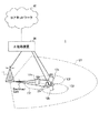
図8は、一実施形態に係る無線通信システムの概略構成の一例を示す図である。無線通信システム1では、LTEシステムのシステム帯域幅(例えば、20MHz)を1単位とする複数の基本周波数ブロック(コンポーネントキャリア)を一体としたキャリアアグリゲーション(CA)及び/又はデュアルコネクティビティ(DC)を適用することができる。なお、無線通信システム1は、SUPER 3G、LTE−A(LTE−Advanced)、IMT−Advanced、4G、5G、FRA(Future Radio Access)、NR(New RAT)などと呼ばれても良い。
FIG. 8 is a diagram showing an example of a schematic configuration of a wireless communication system according to an embodiment. In the
図8に示す無線通信システム1は、マクロセルC1を形成する無線基地局11と、マクロセルC1内に配置され、マクロセルC1よりも狭いスモールセルC2を形成する無線基地局12a〜12cとを備えている。また、マクロセルC1及び各スモールセルC2には、ユーザ端末20が配置されている。セル間で異なるニューメロロジーが適用される構成としてもよい。なお、ニューメロロジーとは、あるRATにおける信号のデザインを特徴付ける通信パラメータのセットのことをいう。
The
ユーザ端末20は、無線基地局11及び無線基地局12の双方に接続することができる。ユーザ端末20は、異なる周波数を用いるマクロセルC1とスモールセルC2を、CA又はDCにより同時に使用することが想定される。また、ユーザ端末20は、複数のセル(CC)(例えば、2個以上のCC)を用いてCA又はDCを適用することができる。また、ユーザ端末は、複数のセルとしてライセンスバンドCCとアンライセンスバンドCCを利用することができる。
The
また、ユーザ端末20は、各セルで、時分割複信(TDD:Time Division Duplex)又は周波数分割複信(FDD:Frequency Division Duplex)を用いて通信を行うことができる。TDDのセル、FDDのセルは、それぞれ、TDDキャリア(フレーム構成タイプ2)、FDDキャリア(フレーム構成タイプ1)等と呼ばれてもよい。
Further, the
また、各セル(キャリア)では、相対的に長い時間長(例えば、1ms)を有するスロット(TTI、通常TTI、ロングTTI、通常サブフレーム、ロングサブフレーム又はサブフレーム等ともいう)、及び/又は、相対的に短い時間長を有するスロット(ミニスロット、ショートTTI又はショートサブフレーム等ともいう)が適用されてもよい。また、各セルで、2以上の時間長のサブフレームが適用されてもよい。 Further, in each cell (carrier), a slot having a relatively long time length (for example, 1 ms) (also referred to as TTI, normal TTI, long TTI, normal subframe, long subframe or subframe, etc.) and / or , Slots with a relatively short time length (also referred to as minislots, short TTIs, short subframes, etc.) may be applied. In addition, subframes having a time length of two or more may be applied to each cell.
ユーザ端末20と無線基地局11との間は、相対的に低い周波数帯域(例えば、2GHz)で帯域幅が狭いキャリア(既存キャリア、Legacy carrierなどと呼ばれる)を用いて通信を行うことができる。一方、ユーザ端末20と無線基地局12との間は、相対的に高い周波数帯域(例えば、3.5GHz、5GHz、30〜70GHzなど)で帯域幅が広いキャリアが用いられてもよいし、無線基地局11との間と同じキャリアが用いられてもよい。なお、各無線基地局が利用する周波数帯域の構成はこれに限られない。
Communication can be performed between the
無線基地局11と無線基地局12との間(又は、2つの無線基地局12間)は、有線接続(例えば、CPRI(Common Public Radio Interface)に準拠した光ファイバ、X2インターフェースなど)又は無線接続する構成とすることができる。
A wired connection (for example, an optical fiber compliant with CPRI (Common Public Radio Interface), an X2 interface, etc.) or a wireless connection is provided between the
無線基地局11及び各無線基地局12は、それぞれ上位局装置30に接続され、上位局装置30を介してコアネットワーク40に接続される。なお、上位局装置30には、例えば、アクセスゲートウェイ装置、無線ネットワークコントローラ(RNC)、モビリティマネジメントエンティティ(MME)などが含まれるが、これに限定されない。また、各無線基地局12は、無線基地局11を介して上位局装置30に接続されてもよい。
The
なお、無線基地局11は、相対的に広いカバレッジを有する無線基地局であり、マクロ基地局、集約ノード、eNB(eNodeB)、送受信ポイント、などと呼ばれてもよい。また、無線基地局12は、局所的なカバレッジを有する無線基地局であり、スモール基地局、マイクロ基地局、ピコ基地局、フェムト基地局、HeNB(Home eNodeB)、RRH(Remote Radio Head)、送受信ポイントなどと呼ばれてもよい。以下、無線基地局11及び12を区別しない場合は、無線基地局10と総称する。
The
各ユーザ端末20は、LTE、LTE−Aなどの各種通信方式に対応した端末であり、移動通信端末だけでなく固定通信端末を含んでもよい。また、ユーザ端末20は、他のユーザ端末20との間で端末間通信(D2D)を行うことができる。
Each
無線通信システム1においては、無線アクセス方式として、下りリンク(DL)にOFDMA(直交周波数分割多元接続)が適用でき、上りリンク(UL)にSC−FDMA(シングルキャリア−周波数分割多元接続)が適用できる。OFDMAは、周波数帯域を複数の狭い周波数帯域(サブキャリア)に分割し、各サブキャリアにデータをマッピングして通信を行うマルチキャリア伝送方式である。SC−FDMAは、システム帯域幅を端末毎に1つ又は連続したリソースブロックからなる帯域に分割し、複数の端末が互いに異なる帯域を用いることで、端末間の干渉を低減するシングルキャリア伝送方式である。なお、上り及び下りの無線アクセス方式は、これらの組み合わせに限られず、ULでOFDMAが用いられてもよい。また、端末間通信に用いられるサイドリンク(SL)にSC−FDMAを適用できる。
In the
無線通信システム1では、DLチャネルとして、各ユーザ端末20で共有されるDLデータチャネル(PDSCH:Physical Downlink Shared Channel、DL共有チャネル等ともいう)、ブロードキャストチャネル(PBCH:Physical Broadcast Channel)、L1/L2制御チャネルなどが用いられる。PDSCHにより、ユーザデータ、上位レイヤ制御情報、SIB(System Information Block)などの少なくとも一つが伝送される。また、PBCHにより、MIB(Master Information Block)が伝送される。
In the
L1/L2制御チャネルは、DL制御チャネル(PDCCH(Physical Downlink Control Channel)及び/又はEPDCCH(Enhanced Physical Downlink Control Channel))、PCFICH(Physical Control Format Indicator Channel)、PHICH(Physical Hybrid-ARQ Indicator Channel)などを含む。PDCCHにより、PDSCH及びPUSCHのスケジューリング情報を含む下り制御情報(DCI:Downlink Control Information)などが伝送される。PCFICHにより、PDCCHに用いるOFDMシンボル数が伝送される。EPDCCHは、PDSCHと周波数分割多重され、PDCCHと同様にDCIなどの伝送に用いられる。PHICH、PDCCH、EPDCCHの少なくとも一つにより、PUSCHの再送制御情報(A/N、HARQ−ACK、HARQ−ACKビット又はA/Nコードブック等ともいう)を伝送できる。 The L1 / L2 control channels include DL control channels (PDCCH (Physical Downlink Control Channel) and / or EPDCCH (Enhanced Physical Downlink Control Channel)), PCFICH (Physical Control Format Indicator Channel), PHICH (Physical Hybrid-ARQ Indicator Channel), and the like. including. Downlink control information (DCI) including scheduling information of PDSCH and PUSCH is transmitted by PDCCH. The number of OFDM symbols used for PDCCH is transmitted by PCFICH. EPDCCH is frequency-division-multiplexed with PDSCH and is used for transmission of DCI and the like like PDCCH. PUSCH retransmission control information (also referred to as A / N, HARQ-ACK, HARQ-ACK bit, A / N codebook, etc.) can be transmitted by at least one of PHICH, PDCCH, and EPDCCH.
無線通信システム1では、ULチャネルとして、各ユーザ端末20で共有されるULデータチャネル(PUSCH:Physical Uplink Shared Channel、UL共有チャネル等ともいう)、UL制御チャネル(PUCCH:Physical Uplink Control Channel)、ランダムアクセスチャネル(PRACH:Physical Random Access Channel)などが用いられる。PUSCHにより、ユーザデータ、上位レイヤ制御情報が伝送される。PDSCHの再送制御情報(A/N、HARQ−ACK)チャネル状態情報(CSI)などの少なくとも一つを含む上り制御情報(UCI:Uplink Control Information)は、PUSCH又はPUCCHにより、伝送される。PRACHにより、セルとの接続確立のためのランダムアクセスプリアンブルを伝送できる。
In the
<無線基地局>
図9は、一実施形態に係る無線基地局の全体構成の一例を示す図である。無線基地局10は、複数の送受信アンテナ101と、アンプ部102と、送受信部103と、ベースバンド信号処理部104と、呼処理部105と、伝送路インターフェース106とを備えている。なお、送受信アンテナ101、アンプ部102、送受信部103は、それぞれ1つ以上を含むように構成されてもよい。無線基地局10は、ULにおいて「受信装置」を構成し、DLにおいて「送信装置」を構成してもよい。<Wireless base station>
FIG. 9 is a diagram showing an example of the overall configuration of the radio base station according to the embodiment. The radio base station 10 includes a plurality of transmission /
下りリンクにより無線基地局10からユーザ端末20に送信されるユーザデータは、上位局装置30から伝送路インターフェース106を介してベースバンド信号処理部104に入力される。
The user data transmitted from the radio base station 10 to the
ベースバンド信号処理部104では、ユーザデータに関して、PDCP(Packet Data Convergence Protocol)レイヤの処理、ユーザデータの分割・結合、RLC(Radio Link Control)再送制御などのRLCレイヤの送信処理、MAC(Medium Access Control)再送制御(例えば、HARQ(Hybrid Automatic Repeat reQuest)の処理)、スケジューリング、伝送フォーマット選択、チャネル符号化、レートマッチング、スクランブリング、逆高速フーリエ変換(IFFT:Inverse Fast Fourier Transform)処理及びプリコーディング処理の少なくとも一つなどの送信処理が行われて送受信部103に転送される。また、下り制御信号に関しても、チャネル符号化及び/又は逆高速フーリエ変換などの送信処理が行われて、送受信部103に転送される。
The baseband
送受信部103は、ベースバンド信号処理部104からアンテナ毎にプリコーディングして出力されたベースバンド信号を無線周波数帯に変換して送信する。送受信部103で周波数変換された無線周波数信号は、アンプ部102により増幅され、送受信アンテナ101から送信される。
The transmission /
本発明に係る技術分野での共通認識に基づいて説明されるトランスミッター/レシーバー、送受信回路又は送受信装置から構成することができる。なお、送受信部103は、一体の送受信部として構成されてもよいし、送信部及び受信部から構成されてもよい。
It can consist of a transmitter / receiver, a transmitter / receiver circuit or a transmitter / receiver described based on common recognition in the technical field according to the present invention. The transmission /
一方、UL信号については、送受信アンテナ101で受信された無線周波数信号がアンプ部102で増幅される。送受信部103はアンプ部102で増幅されたUL信号を受信する。送受信部103は、受信信号をベースバンド信号に周波数変換して、ベースバンド信号処理部104に出力する。
On the other hand, as for the UL signal, the radio frequency signal received by the transmission /
ベースバンド信号処理部104では、入力されたUL信号に含まれるULデータに対して、高速フーリエ変換(FFT:Fast Fourier Transform)処理、逆離散フーリエ変換(IDFT:Inverse Discrete Fourier Transform)処理、誤り訂正復号、MAC再送制御の受信処理、RLCレイヤ及びPDCPレイヤの受信処理がなされ、伝送路インターフェース106を介して上位局装置30に転送される。呼処理部105は、通信チャネルの設定、解放などの呼処理、無線基地局10の状態管理、無線リソースの管理の少なくとも一つを行う。
In the baseband
伝送路インターフェース106は、所定のインターフェースを介して、上位局装置30と信号を送受信する。また、伝送路インターフェース106は、基地局間インターフェース(例えば、CPRI(Common Public Radio Interface)に準拠した光ファイバ、X2インターフェース)を介して隣接無線基地局10と信号を送受信(バックホールシグナリング)してもよい。
The
また、送受信部103は、DL信号(例えば、DCI(DLアサインメント、ULグラント、共通DCIの少なくとも一つを含む)、DLデータ(チャネル)、参照信号及び上位レイヤ制御情報の少なくとも一つ)を送信し、及び/又は、UL信号(例えば、ULデータ(チャネル)、UCI、参照信号及び上位レイヤ制御情報の少なくとも一つ)を受信する。
Further, the transmission /
具体的には、送受信部103は、可変長の送信期間(例えば、スロット、ミニスロット、所定のシンボル数)において、DLデータチャネル(例えば、PDSCH)を送信し、及び/又は、ULデータチャネル(例えば、PUSCH)を受信してもよい。
Specifically, the transmission /
送受信部103は、ブランクリソース領域を考慮して送信及び/又は受信処理を行ってもよい。送受信部103は、ブランクリソース領域において、所定の信号(例えば、PDSCH、PUSCH)の送信及び/又は受信処理を行わなくてもよい。
The transmission /
図10は、一実施形態に係る無線基地局の機能構成の一例を示す図である。なお、図10は、本実施の形態における特徴部分の機能ブロックを主に示しており、無線基地局10は、無線通信に必要な他の機能ブロックも有してもよい。図10に示すように、ベースバンド信号処理部104は、制御部301と、送信信号生成部302と、マッピング部303と、受信信号処理部304と、測定部305とを備えている。
FIG. 10 is a diagram showing an example of the functional configuration of the radio base station according to the embodiment. Note that FIG. 10 mainly shows the functional blocks of the feature portion in the present embodiment, and the wireless base station 10 may also have other functional blocks necessary for wireless communication. As shown in FIG. 10, the baseband
制御部301は、無線基地局10全体の制御を実施する。制御部301は、例えば、送信信号生成部302によるDL信号の生成、マッピング部303によるDL信号のマッピング、受信信号処理部304によるUL信号の受信処理(例えば、復調など)及び測定部305による測定の少なくとも一つを制御する。また、制御部301は、データチャネル(DLデータチャネル及び/又はULデータチャネルを含む)のスケジューリングを制御してもよい。
The
制御部301は、所定の帯域幅部分(BWP:Bandwidth part)に関連して、ユーザ端末に対するブランクリソース領域(ブランクリソースパターン)を決定してもよい。制御部301は、当該ブランクリソース領域を考慮して送信及び/又は受信処理を制御してもよい。
The
制御部301は、ブランクリソース領域に関する情報をユーザ端末20に対して送信する制御を行ってもよい。例えば、制御部301は、アクティブなBWPのブランクリソース領域に関する情報を、当該アクティブなBWPの設定情報に含めて通知する制御を行ってもよい。制御部301は、アクティブなBWPのブランクリソース領域に関する情報を、複数のBWPに共通のブランクリソース領域に関する情報として通知する制御を行ってもよい。なお、当該共通のブランクリソース領域は、ユーザ端末20に設定する複数のBWPのうち、少なくとも1つのBWPの周波数帯域外のリソース領域を含んでもよい。
The
制御部301は、以下の(1)から(3)のいずれかを想定してブランクリソース領域を決定してもよい:(1)所定の期間において、所定のBWP(例えば、アクティブなBWP)の帯域幅全体がブランクリソース領域である、(2)所定の期間において、所定のBWPの帯域幅の一部がブランクリソース領域である、(3)所定の期間において、所定のBWPにはブランクリソース領域が含まれない。
The
制御部301は、本発明に係る技術分野での共通認識に基づいて説明されるコントローラ、制御回路又は制御装置から構成することができる。
The
送信信号生成部302は、制御部301からの指示に基づいて、DL信号(DLデータ(チャネル)、DCI、DL参照信号、上位レイヤシグナリングによる制御情報の少なくとも一つを含む)を生成して、マッピング部303に出力してもよい。
The transmission
送信信号生成部302は、本発明に係る技術分野での共通認識に基づいて説明される信号生成器、信号生成回路又は信号生成装置とすることができる。
The transmission
マッピング部303は、制御部301からの指示に基づいて、送信信号生成部302で生成されたDL信号を、所定の無線リソースにマッピングして、送受信部103に出力する。例えば、マッピング部303は、制御部301によって決定される配置パターンを用いて、参照信号を所定の無線リソースにマッピングする。
Based on the instruction from the
マッピング部303は、本発明に係る技術分野での共通認識に基づいて説明されるマッパー、マッピング回路又はマッピング装置とすることができる。
The
受信信号処理部304は、ユーザ端末20から送信されるUL信号の受信処理(例えば、デマッピング、復調、復号など)を行う。例えば、受信信号処理部304は、制御部301によって決定される配置パターンの参照信号を用いて、ULデータチャネルを復調してもよい。具体的には、受信信号処理部304は、受信信号及び/又は受信処理後の信号を、測定部305に出力してもよい。
The reception
受信信号処理部304は、本発明に係る技術分野での共通認識に基づいて説明される信号処理器、信号処理回路又は信号処理装置から構成することができる。また、受信信号処理部304は、本発明に係る受信部を構成することができる。
The received
測定部305は、例えば、参照信号の受信電力(例えば、RSRP(Reference Signal Received Power))及び/又は受信品質(例えば、RSRQ(Reference Signal Received Quality))に基づいて、ULのチャネル品質を測定してもよい。測定結果は、制御部301に出力されてもよい。
The measuring
<ユーザ端末>
図11は、一実施形態に係るユーザ端末の全体構成の一例を示す図である。ユーザ端末20は、MIMO伝送のための複数の送受信アンテナ201と、アンプ部202と、送受信部203と、ベースバンド信号処理部204と、アプリケーション部205と、を備えている。ユーザ端末20は、ULにおいて「送信装置」を構成し、DLにおいて「受信装置」を構成してもよい。<User terminal>
FIG. 11 is a diagram showing an example of the overall configuration of the user terminal according to the embodiment. The
複数の送受信アンテナ201で受信された無線周波数信号は、それぞれアンプ部202で増幅される。各送受信部203はアンプ部202で増幅されたDL信号を受信する。送受信部203は、受信信号をベースバンド信号に周波数変換して、ベースバンド信号処理部204に出力する。
The radio frequency signals received by the plurality of transmission /
ベースバンド信号処理部204は、入力されたベースバンド信号に対して、FFT処理、誤り訂正復号、再送制御の受信処理などの少なくとも一つを行う。DLデータは、アプリケーション部205に転送される。アプリケーション部205は、物理レイヤ及びMACレイヤより上位のレイヤに関する処理などを行う。
The baseband
一方、ULデータについては、アプリケーション部205からベースバンド信号処理部204に入力される。ベースバンド信号処理部204では、再送制御処理(例えば、HARQの処理)、チャネル符号化、レートマッチング、パンクチャ、離散フーリエ変換(DFT:Discrete Fourier Transform)処理、IFFT処理などの少なくとも一つが行われて各送受信部203に転送される。UCI(例えば、DL信号のA/N、チャネル状態情報(CSI)、スケジューリング要求(SR)の少なくとも一つなど)についても、チャネル符号化、レートマッチング、パンクチャ、DFT処理及びIFFT処理などの少なくとも一つが行われて各送受信部203に転送される。
On the other hand, the UL data is input from the
送受信部203は、ベースバンド信号処理部204から出力されたベースバンド信号を無線周波数帯に変換して送信する。送受信部203で周波数変換された無線周波数信号は、アンプ部202により増幅され、送受信アンテナ201から送信される。
The transmission /
また、送受信部203は、DL信号(例えば、DCI(DLアサインメント、ULグラント、共通DCIの少なくとも一つを含む)、DLデータ(チャネル)、参照信号及び上位レイヤ制御情報の少なくとも一つ)を受信し、及び/又は、UL信号(例えば、ULデータ(チャネル)、UCI、参照信号及び上位レイヤ制御情報の少なくとも一つ)を送信する。
Further, the transmission /
具体的には、送受信部203は、可変長の送信期間(例えば、スロット、ミニスロット、所定のシンボル数)において、DLデータチャネル(例えば、PDSCH)を受信し、及び/又は、ULデータチャネル(例えば、PUSCH)を送信してもよい。
Specifically, the transmission /
送受信部203は、ブランクリソース領域を考慮して送信及び/又は受信処理を行ってもよい。送受信部203は、ブランクリソース領域において、所定の信号(例えば、PDSCH、PUSCH)の送信及び/又は受信処理を行わなくてもよい。
The transmission /
送受信部203は、本発明に係る技術分野での共通認識に基づいて説明されるトランスミッター/レシーバー、送受信回路又は送受信装置とすることができる。また、送受信部203は、一体の送受信部として構成されてもよいし、送信部及び受信部から構成されてもよい。
The transmitter /
図12は、一実施形態に係るユーザ端末の機能構成の一例を示す図である。なお、図12においては、本実施の形態における特徴部分の機能ブロックを主に示しており、ユーザ端末20は、無線通信に必要な他の機能ブロックも有してもよい。図12に示すように、ユーザ端末20が有するベースバンド信号処理部204は、制御部401と、送信信号生成部402と、マッピング部403と、受信信号処理部404と、測定部405と、を備えている。
FIG. 12 is a diagram showing an example of the functional configuration of the user terminal according to the embodiment. Note that FIG. 12 mainly shows the functional blocks of the feature portion in the present embodiment, and the
制御部401は、ユーザ端末20全体の制御を実施する。制御部401は、例えば、送信信号生成部402によるUL信号の生成、マッピング部403によるUL信号のマッピング、受信信号処理部404によるDL信号の受信処理及び測定部405による測定の少なくとも一つを制御する。
The
具体的には、制御部401は、DL制御チャネルをモニタリング(ブラインド復号)し、ユーザ端末20に対するデータチャネルのスケジューリング用のDCIを検出してもよい。制御部401は、当該DCIに基づいてDLデータチャネルの受信を制御してもよい。また、制御部401は、当該DCIに基づいてULデータチャネルの送信を制御してもよい。
Specifically, the
制御部401は、所定の帯域幅部分(BWP:Bandwidth part)に関連して設定されるブランクリソース領域(ブランクリソースパターン)を判断してもよい。制御部401は、当該ブランクリソース領域を考慮して送信及び/又は受信処理を制御してもよい。
The
制御部401は、アクティブなBWPのブランクリソース領域を、当該アクティブなBWPの設定情報に基づいて判断してもよい。制御部401は、アクティブなBWPのブランクリソース領域が、複数のBWPに共通のブランクリソース領域に含まれると想定してもよい。なお、当該共通のブランクリソース領域は、アクティブなBWPの周波数帯域外のリソース領域を含んでもよい。
The
制御部401は、以下の(1)から(3)のいずれかを想定してブランクリソース領域を判断してもよい:(1)所定の期間において、所定のBWP(例えば、アクティブなBWP)の帯域幅全体がブランクリソース領域である、(2)所定の期間において、所定のBWPの帯域幅の一部がブランクリソース領域である、(3)所定の期間において、所定のBWPにはブランクリソース領域が含まれない。
The
制御部401は、本発明に係る技術分野での共通認識に基づいて説明されるコントローラ、制御回路又は制御装置から構成することができる。
The
送信信号生成部402は、制御部401からの指示に基づいて、UL信号、DL信号の再送制御情報を生成(例えば、符号化、レートマッチング、パンクチャ、変調など)して、マッピング部403に出力する。送信信号生成部402は、本発明に係る技術分野での共通認識に基づいて説明される信号生成器、信号生成回路又は信号生成装置とすることができる。
The transmission
マッピング部403は、制御部401からの指示に基づいて、送信信号生成部402で生成されたUL信号、DL信号の再送制御情報を無線リソースにマッピングして、送受信部203へ出力する。例えば、マッピング部403は、制御部401によって決定される配置パターンを用いて、参照信号を所定の無線リソースにマッピングする。
Based on the instruction from the
マッピング部403は、本発明に係る技術分野での共通認識に基づいて説明されるマッパー、マッピング回路又はマッピング装置とすることができる。
The
受信信号処理部404は、DL信号の受信処理(例えば、デマッピング、復調及び復号の少なくとも一つなど)を行う。例えば、受信信号処理部404は、制御部401によって決定される配置パターンの参照信号を用いて、DLデータチャネルを復調してもよい。
The reception
また、受信信号処理部404は、受信信号及び/又は受信処理後の信号を、制御部401及び/又は測定部405に出力してもよい。受信信号処理部404は、例えば、上位レイヤシグナリングによる上位レイヤ制御情報、L1/L2制御情報(例えば、ULグラント及び/又はDLアサインメント)などを、制御部401に出力する。
Further, the reception
受信信号処理部404は、本発明に係る技術分野での共通認識に基づいて説明される信号処理器、信号処理回路又は信号処理装置から構成することができる。また、受信信号処理部404は、本発明に係る受信部を構成することができる。
The received
測定部405は、無線基地局10からの参照信号(例えば、CSI−RS)に基づいて、チャネル状態を測定し、測定結果を制御部401に出力する。なお、チャネル状態の測定は、CC毎に行われてもよい。
The
測定部405は、本発明に係る技術分野での共通認識に基づいて説明される信号処理器、信号処理回路又は信号処理装置、並びに、測定器、測定回路又は測定装置から構成することができる。
The measuring
(ハードウェア構成)
なお、上記実施形態の説明に用いたブロック図は、機能単位のブロックを示している。これらの機能ブロック(構成部)は、ハードウェア及び/又はソフトウェアの任意の組み合わせによって実現される。また、各機能ブロックの実現方法は特に限定されない。すなわち、各機能ブロックは、物理的及び/又は論理的に結合した1つの装置を用いて実現されてもよいし、物理的及び/又は論理的に分離した2つ以上の装置を直接的及び/又は間接的に(例えば、有線及び/又は無線を用いて)接続し、これら複数の装置を用いて実現されてもよい。(Hardware configuration)
The block diagram used in the description of the above embodiment shows a block of functional units. These functional blocks (components) are realized by any combination of hardware and / or software. Further, the method of realizing each functional block is not particularly limited. That is, each functional block may be implemented using one physically and / or logically coupled device, or two or more physically and / or logically separated devices directly and / /. Alternatively, it may be indirectly connected (eg, by wire and / or wirelessly) and realized by using these plurality of devices.
例えば、本発明の一実施形態における無線基地局、ユーザ端末などは、本発明の無線通信方法の処理を行うコンピュータとして機能してもよい。図13は、一実施形態に係る無線基地局及びユーザ端末のハードウェア構成の一例を示す図である。上述の無線基地局10及びユーザ端末20は、物理的には、プロセッサ1001、メモリ1002、ストレージ1003、通信装置1004、入力装置1005、出力装置1006、バス1007などを含むコンピュータ装置として構成されてもよい。
For example, the wireless base station, user terminal, or the like in one embodiment of the present invention may function as a computer that processes the wireless communication method of the present invention. FIG. 13 is a diagram showing an example of the hardware configuration of the radio base station and the user terminal according to the embodiment. The radio base station 10 and the
なお、以下の説明では、「装置」という文言は、回路、デバイス、ユニットなどに読み替えることができる。無線基地局10及びユーザ端末20のハードウェア構成は、図に示した各装置を1つ又は複数含むように構成されてもよいし、一部の装置を含まずに構成されてもよい。
In the following description, the word "device" can be read as a circuit, a device, a unit, or the like. The hardware configuration of the radio base station 10 and the
例えば、プロセッサ1001は1つだけ図示されているが、複数のプロセッサがあってもよい。また、処理は、1のプロセッサによって実行されてもよいし、処理が同時に、逐次に、又はその他の手法を用いて、1以上のプロセッサによって実行されてもよい。なお、プロセッサ1001は、1以上のチップによって実装されてもよい。
For example, although only one
無線基地局10及びユーザ端末20における各機能は、例えば、プロセッサ1001、メモリ1002などのハードウェア上に所定のソフトウェア(プログラム)を読み込ませることによって、プロセッサ1001が演算を行い、通信装置1004を介する通信を制御したり、メモリ1002及びストレージ1003におけるデータの読み出し及び/又は書き込みを制御したりすることによって実現される。
For each function of the radio base station 10 and the
プロセッサ1001は、例えば、オペレーティングシステムを動作させてコンピュータ全体を制御する。プロセッサ1001は、周辺装置とのインターフェース、制御装置、演算装置、レジスタなどを含む中央処理装置(CPU:Central Processing Unit)によって構成されてもよい。例えば、上述のベースバンド信号処理部104(204)、呼処理部105などは、プロセッサ1001によって実現されてもよい。
また、プロセッサ1001は、プログラム(プログラムコード)、ソフトウェアモジュール、データなどを、ストレージ1003及び/又は通信装置1004からメモリ1002に読み出し、これらに従って各種の処理を実行する。プログラムとしては、上述の実施形態において説明した動作の少なくとも一部をコンピュータに実行させるプログラムが用いられる。例えば、ユーザ端末20の制御部401は、メモリ1002に格納され、プロセッサ1001において動作する制御プログラムによって実現されてもよく、他の機能ブロックについても同様に実現されてもよい。
Further, the
メモリ1002は、コンピュータ読み取り可能な記録媒体であり、例えば、ROM(Read Only Memory)、EPROM(Erasable Programmable ROM)、EEPROM(Electrically EPROM)、RAM(Random Access Memory)、その他の適切な記憶媒体の少なくとも1つによって構成されてもよい。メモリ1002は、レジスタ、キャッシュ、メインメモリ(主記憶装置)などと呼ばれてもよい。メモリ1002は、本発明の一実施形態に係る無線通信方法を実施するために実行可能なプログラム(プログラムコード)、ソフトウェアモジュールなどを保存することができる。
The
ストレージ1003は、コンピュータ読み取り可能な記録媒体であり、例えば、フレキシブルディスク、フロッピー(登録商標)ディスク、光磁気ディスク(例えば、コンパクトディスク(CD−ROM(Compact Disc ROM)など)、デジタル多用途ディスク、Blu−ray(登録商標)ディスク)、リムーバブルディスク、ハードディスクドライブ、スマートカード、フラッシュメモリデバイス(例えば、カード、スティック、キードライブ)、磁気ストライプ、データベース、サーバ、その他の適切な記憶媒体の少なくとも1つによって構成されてもよい。ストレージ1003は、補助記憶装置と呼ばれてもよい。
The
通信装置1004は、有線及び/又は無線ネットワークを介してコンピュータ間の通信を行うためのハードウェア(送受信デバイス)であり、例えばネットワークデバイス、ネットワークコントローラ、ネットワークカード、通信モジュールなどともいう。通信装置1004は、例えば周波数分割複信(FDD:Frequency Division Duplex)及び/又は時分割複信(TDD:Time Division Duplex)を実現するために、高周波スイッチ、デュプレクサ、フィルタ、周波数シンセサイザなどを含んで構成されてもよい。例えば、上述の送受信アンテナ101(201)、アンプ部102(202)、送受信部103(203)、伝送路インターフェース106などは、通信装置1004によって実現されてもよい。
The
入力装置1005は、外部からの入力を受け付ける入力デバイス(例えば、キーボード、マウス、マイクロフォン、スイッチ、ボタン、センサなど)である。出力装置1006は、外部への出力を実施する出力デバイス(例えば、ディスプレイ、スピーカー、LED(Light Emitting Diode)ランプなど)である。なお、入力装置1005及び出力装置1006は、一体となった構成(例えば、タッチパネル)であってもよい。
The
また、プロセッサ1001、メモリ1002などの各装置は、情報を通信するためのバス1007によって接続される。バス1007は、単一のバスを用いて構成されてもよいし、装置間ごとに異なるバスを用いて構成されてもよい。
Further, each device such as the
また、無線基地局10及びユーザ端末20は、マイクロプロセッサ、デジタル信号プロセッサ(DSP:Digital Signal Processor)、ASIC(Application Specific Integrated Circuit)、PLD(Programmable Logic Device)、FPGA(Field Programmable Gate Array)などのハードウェアを含んで構成されてもよく、当該ハードウェアを用いて各機能ブロックの一部又は全てが実現されてもよい。例えば、プロセッサ1001は、これらのハードウェアの少なくとも1つを用いて実装されてもよい。
Further, the radio base station 10 and the
(変形例)
なお、本明細書において説明した用語及び/又は本明細書の理解に必要な用語については、同一の又は類似する意味を有する用語と置き換えてもよい。例えば、チャネル及び/又はシンボルは信号(シグナリング)であってもよい。また、信号はメッセージであってもよい。参照信号は、RS(Reference Signal)と略称することもでき、適用される標準によってパイロット(Pilot)、パイロット信号などと呼ばれてもよい。また、コンポーネントキャリア(CC:Component Carrier)は、セル、周波数キャリア、キャリア周波数などと呼ばれてもよい。(Modification example)
The terms described in the present specification and / or the terms necessary for understanding the present specification may be replaced with terms having the same or similar meanings. For example, the channel and / or symbol may be a signal (signaling). Also, the signal may be a message. The reference signal may be abbreviated as RS (Reference Signal), and may be referred to as a pilot (Pilot), a pilot signal, or the like depending on the applied standard. Further, the component carrier (CC: Component Carrier) may be referred to as a cell, a frequency carrier, a carrier frequency, or the like.
また、無線フレームは、時間領域において1つ又は複数の期間(フレーム)によって構成されてもよい。無線フレームを構成する当該1つ又は複数の各期間(フレーム)は、サブフレームと呼ばれてもよい。さらに、サブフレームは、時間領域において1つ又は複数のスロットによって構成されてもよい。サブフレームは、ニューメロロジーに依存しない固定の時間長(例えば、1ms)であってもよい。 Further, the radio frame may be composed of one or a plurality of periods (frames) in the time domain. Each of the one or more periods (frames) constituting the wireless frame may be referred to as a subframe. Further, the subframe may be composed of one or more slots in the time domain. The subframe may have a fixed time length (eg, 1 ms) that is independent of numerology.
さらに、スロットは、時間領域において1つ又は複数のシンボル(OFDM(Orthogonal Frequency Division Multiplexing)シンボル、SC−FDMA(Single Carrier Frequency Division Multiple Access)シンボルなど)によって構成されてもよい。また、スロットは、ニューメロロジーに基づく時間単位であってもよい。また、スロットは、複数のミニスロットを含んでもよい。各ミニスロットは、時間領域において1つ又は複数のシンボルによって構成されてもよい。また、ミニスロットは、サブスロットと呼ばれてもよい。 Further, the slot may be composed of one or more symbols in the time domain (OFDM (Orthogonal Frequency Division Multiplexing) symbol, SC-FDMA (Single Carrier Frequency Division Multiple Access) symbol, etc.). In addition, the slot may be a time unit based on numerology. Further, the slot may include a plurality of mini slots. Each minislot may consist of one or more symbols in the time domain. The mini-slot may also be referred to as a sub-slot.
無線フレーム、サブフレーム、スロット、ミニスロット及びシンボルは、いずれも信号を伝送する際の時間単位を表す。無線フレーム、サブフレーム、スロット、ミニスロット及びシンボルは、それぞれに対応する別の呼称が用いられてもよい。例えば、1サブフレームは送信時間間隔(TTI:Transmission Time Interval)と呼ばれてもよいし、複数の連続したサブフレームがTTIと呼ばれてよいし、1スロット又は1ミニスロットがTTIと呼ばれてもよい。つまり、サブフレーム及び/又はTTIは、既存のLTEにおけるサブフレーム(1ms)であってもよいし、1msより短い期間(例えば、1−13シンボル)であってもよいし、1msより長い期間であってもよい。なお、TTIを表す単位は、サブフレームではなくスロット、ミニスロットなどと呼ばれてもよい。 Radio frames, subframes, slots, minislots and symbols all represent time units when transmitting signals. The radio frame, subframe, slot, minislot and symbol may have different names corresponding to each. For example, one subframe may be referred to as a transmission time interval (TTI), a plurality of consecutive subframes may be referred to as a TTI, and one slot or one minislot may be referred to as a TTI. You may. That is, the subframe and / or TTI may be a subframe (1 ms) in existing LTE, a period shorter than 1 ms (eg, 1-13 symbols), or a period longer than 1 ms. There may be. The unit representing TTI may be called a slot, a mini slot, or the like instead of a subframe.
ここで、TTIは、例えば、無線通信におけるスケジューリングの最小時間単位のことをいう。例えば、LTEシステムでは、無線基地局が各ユーザ端末に対して、無線リソース(各ユーザ端末において使用することが可能な周波数帯域幅、送信電力など)を、TTI単位で割り当てるスケジューリングを行う。なお、TTIの定義はこれに限られない。 Here, TTI refers to, for example, the minimum time unit of scheduling in wireless communication. For example, in the LTE system, the radio base station schedules each user terminal to allocate radio resources (frequency bandwidth that can be used in each user terminal, transmission power, etc.) in TTI units. The definition of TTI is not limited to this.
TTIは、チャネル符号化されたデータパケット(トランスポートブロック)、コードブロック、及び/又はコードワードの送信時間単位であってもよいし、スケジューリング、リンクアダプテーションなどの処理単位となってもよい。なお、TTIが与えられたとき、実際にトランスポートブロック、コードブロック、及び/又はコードワードがマッピングされる時間区間(例えば、シンボル数)は、当該TTIよりも短くてもよい。 The TTI may be a transmission time unit of a channel-encoded data packet (transport block), a code block, and / or a code word, or may be a processing unit such as scheduling and link adaptation. When a TTI is given, the time interval (for example, the number of symbols) to which the transport block, the code block, and / or the code word is actually mapped may be shorter than the TTI.
なお、1スロット又は1ミニスロットがTTIと呼ばれる場合、1以上のTTI(すなわち、1以上のスロット又は1以上のミニスロット)が、スケジューリングの最小時間単位となってもよい。また、当該スケジューリングの最小時間単位を構成するスロット数(ミニスロット数)は制御されてもよい。 When one slot or one minislot is called TTI, one or more TTIs (that is, one or more slots or one or more minislots) may be the minimum time unit for scheduling. Further, the number of slots (number of mini-slots) constituting the minimum time unit of the scheduling may be controlled.
1msの時間長を有するTTIは、通常TTI(LTE Rel.8−12におけるTTI)、ノーマルTTI、ロングTTI、通常サブフレーム、ノーマルサブフレーム、又はロングサブフレームなどと呼ばれてもよい。通常TTIより短いTTIは、短縮TTI、ショートTTI、部分TTI(partial又はfractional TTI)、短縮サブフレーム、ショートサブフレーム、ミニスロット、又は、サブスロットなどと呼ばれてもよい。 A TTI having a time length of 1 ms may be referred to as a normal TTI (TTI in LTE Rel. 8-12), a normal TTI, a long TTI, a normal subframe, a normal subframe, a long subframe, or the like. A TTI shorter than a normal TTI may be referred to as a shortened TTI, a short TTI, a partial TTI (partial or fractional TTI), a shortened subframe, a short subframe, a minislot, or a subslot.
なお、ロングTTI(例えば、通常TTI、サブフレームなど)は、1msを超える時間長を有するTTIで読み替えてもよいし、ショートTTI(例えば、短縮TTIなど)は、ロングTTIのTTI長未満かつ1ms以上のTTI長を有するTTIで読み替えてもよい。 The long TTI (for example, normal TTI, subframe, etc.) may be read as a TTI having a time length of more than 1 ms, and the short TTI (for example, shortened TTI, etc.) is less than the TTI length of the long TTI and 1 ms. It may be read as a TTI having the above TTI length.
リソースブロック(RB:Resource Block)は、時間領域及び周波数領域のリソース割当単位であり、周波数領域において、1つ又は複数個の連続した副搬送波(サブキャリア(subcarrier))を含んでもよい。また、RBは、時間領域において、1つ又は複数個のシンボルを含んでもよく、1スロット、1ミニスロット、1サブフレーム又は1TTIの長さであってもよい。1TTI、1サブフレームは、それぞれ1つ又は複数のリソースブロックによって構成されてもよい。なお、1つ又は複数のRBは、物理リソースブロック(PRB:Physical RB)、サブキャリアグループ(SCG:Sub-Carrier Group)、リソースエレメントグループ(REG:Resource Element Group)、PRBペア、RBペアなどと呼ばれてもよい。 A resource block (RB) is a resource allocation unit in a time domain and a frequency domain, and may include one or more consecutive subcarriers in the frequency domain. The RB may also include one or more symbols in the time domain and may be one slot, one minislot, one subframe or one TTI in length. One TTI and one subframe may each be composed of one or more resource blocks. One or more RBs include a physical resource block (PRB: Physical RB), a sub-carrier group (SCG: Sub-Carrier Group), a resource element group (REG: Resource Element Group), a PRB pair, an RB pair, and the like. May be called.
また、リソースブロックは、1つ又は複数のリソースエレメント(RE:Resource Element)によって構成されてもよい。例えば、1REは、1サブキャリア及び1シンボルの無線リソース領域であってもよい。 Further, the resource block may be composed of one or a plurality of resource elements (RE: Resource Element). For example, 1RE may be a radio resource area of 1 subcarrier and 1 symbol.
なお、上述した無線フレーム、サブフレーム、スロット、ミニスロット及びシンボルなどの構造は例示に過ぎない。例えば、無線フレームに含まれるサブフレームの数、サブフレーム又は無線フレームあたりのスロットの数、スロット内に含まれるミニスロットの数、スロット又はミニスロットに含まれるシンボル及びRBの数、RBに含まれるサブキャリアの数、並びにTTI内のシンボル数、シンボル長、サイクリックプレフィックス(CP:Cyclic Prefix)長などの構成は、様々に変更することができる。 The above-mentioned structures such as a wireless frame, a subframe, a slot, a minislot, and a symbol are merely examples. For example, the number of subframes contained in a wireless frame, the number of slots per subframe or wireless frame, the number of minislots contained within a slot, the number of symbols and RBs contained in a slot or minislot, included in the RB. The number of subcarriers, the number of symbols in the TTI, the symbol length, the cyclic prefix (CP) length, and the like can be changed in various ways.
また、本明細書において説明した情報、パラメータなどは、絶対値を用いて表されてもよいし、所定の値からの相対値を用いて表されてもよいし、対応する別の情報を用いて表されてもよい。例えば、無線リソースは、所定のインデックスによって指示されてもよい。 In addition, the information, parameters, etc. described in the present specification may be expressed using absolute values, relative values from predetermined values, or other corresponding information. May be expressed as. For example, radio resources may be indicated by a given index.
本明細書においてパラメータなどに使用する名称は、いかなる点においても限定的な名称ではない。例えば、様々なチャネル(PUCCH(Physical Uplink Control Channel)、PDCCH(Physical Downlink Control Channel)など)及び情報要素は、あらゆる好適な名称によって識別できるので、これらの様々なチャネル及び情報要素に割り当てている様々な名称は、いかなる点においても限定的な名称ではない。 The names used for parameters and the like in the present specification are not limited in any respect. For example, various channels (PUCCH (Physical Uplink Control Channel), PDCCH (Physical Downlink Control Channel), etc.) and information elements can be identified by any suitable name, and therefore various assigned to these various channels and information elements. The name is not limited in any respect.
本明細書において説明した情報、信号などは、様々な異なる技術のいずれかを使用して表されてもよい。例えば、上記の説明全体に渡って言及され得るデータ、命令、コマンド、情報、信号、ビット、シンボル、チップなどは、電圧、電流、電磁波、磁界若しくは磁性粒子、光場若しくは光子、又はこれらの任意の組み合わせによって表されてもよい。 The information, signals, etc. described herein may be represented using any of a variety of different techniques. For example, data, instructions, commands, information, signals, bits, symbols, chips, etc. that may be referred to throughout the above description are voltages, currents, electromagnetic waves, magnetic fields or magnetic particles, light fields or photons, or any of these. It may be represented by a combination of.
また、情報、信号などは、上位レイヤから下位レイヤ、及び/又は下位レイヤから上位レイヤへ出力され得る。情報、信号などは、複数のネットワークノードを介して入出力されてもよい。 Further, information, signals and the like can be output from the upper layer to the lower layer and / or from the lower layer to the upper layer. Information, signals, etc. may be input / output via a plurality of network nodes.
入出力された情報、信号などは、特定の場所(例えば、メモリ)に保存されてもよいし、管理テーブルを用いて管理してもよい。入出力される情報、信号などは、上書き、更新又は追記をされ得る。出力された情報、信号などは、削除されてもよい。入力された情報、信号などは、他の装置へ送信されてもよい。 The input / output information, signals, and the like may be stored in a specific location (for example, a memory), or may be managed using a management table. Input / output information, signals, etc. can be overwritten, updated, or added. The output information, signals, etc. may be deleted. The input information, signals, etc. may be transmitted to other devices.
情報の通知は、本明細書において説明した態様/実施形態に限られず、他の方法を用いて行われてもよい。例えば、情報の通知は、物理レイヤシグナリング(例えば、下り制御情報(DCI:Downlink Control Information)、上り制御情報(UCI:Uplink Control Information))、上位レイヤシグナリング(例えば、RRC(Radio Resource Control)シグナリング、ブロードキャスト情報(マスタ情報ブロック(MIB:Master Information Block)、システム情報ブロック(SIB:System Information Block)など)、MAC(Medium Access Control)シグナリング)、その他の信号又はこれらの組み合わせによって実施されてもよい。 The notification of information is not limited to the embodiments / embodiments described herein, and may be made using other methods. For example, information notification includes physical layer signaling (for example, downlink control information (DCI), uplink control information (UCI)), upper layer signaling (for example, RRC (Radio Resource Control) signaling, etc.). It may be carried out by broadcast information (Master Information Block (MIB), System Information Block (SIB), etc.), MAC (Medium Access Control) signaling, other signals, or a combination thereof.
なお、物理レイヤシグナリングは、L1/L2(Layer 1/Layer 2)制御情報(L1/L2制御信号)、L1制御情報(L1制御信号)などと呼ばれてもよい。また、RRCシグナリングは、RRCメッセージと呼ばれてもよく、例えば、RRC接続セットアップ(RRCConnectionSetup)メッセージ、RRC接続再構成(RRCConnectionReconfiguration)メッセージなどであってもよい。また、MACシグナリングは、例えば、MAC制御要素(MAC CE(Control Element))を用いて通知されてもよい。
The physical layer signaling may be referred to as L1 / L2 (
また、所定の情報の通知(例えば、「Xであること」の通知)は、明示的な通知に限られず、暗示的に(例えば、当該所定の情報の通知を行わないことによって又は別の情報の通知によって)行われてもよい。 In addition, the notification of predetermined information (for example, the notification of "being X") is not limited to the explicit notification, but implicitly (for example, by not notifying the predetermined information or another information). May be done (by notification of).
判定は、1ビットで表される値(0か1か)によって行われてもよいし、真(true)又は偽(false)で表される真偽値(boolean)によって行われてもよいし、数値の比較(例えば、所定の値との比較)によって行われてもよい。 The determination may be made by a value represented by 1 bit (0 or 1), or by a boolean value represented by true or false. , May be done by numerical comparison (eg, comparison with a given value).
ソフトウェアは、ソフトウェア、ファームウェア、ミドルウェア、マイクロコード、ハードウェア記述言語と呼ばれるか、他の名称で呼ばれるかを問わず、命令、命令セット、コード、コードセグメント、プログラムコード、プログラム、サブプログラム、ソフトウェアモジュール、アプリケーション、ソフトウェアアプリケーション、ソフトウェアパッケージ、ルーチン、サブルーチン、オブジェクト、実行可能ファイル、実行スレッド、手順、機能などを意味するよう広く解釈されるべきである。 Software, whether referred to as software, firmware, middleware, microcode, hardware description language, or other names, is an instruction, instruction set, code, code segment, program code, program, subprogram, software module. , Applications, software applications, software packages, routines, subroutines, objects, executable files, execution threads, procedures, functions, etc. should be broadly interpreted.
また、ソフトウェア、命令、情報などは、伝送媒体を介して送受信されてもよい。例えば、ソフトウェアが、有線技術(同軸ケーブル、光ファイバケーブル、ツイストペア、デジタル加入者回線(DSL:Digital Subscriber Line)など)及び/又は無線技術(赤外線、マイクロ波など)を使用してウェブサイト、サーバ、又は他のリモートソースから送信される場合、これらの有線技術及び/又は無線技術は、伝送媒体の定義内に含まれる。 Further, software, instructions, information and the like may be transmitted and received via a transmission medium. For example, software uses wired technology (coaxial cable, fiber optic cable, twisted pair, digital subscriber line (DSL), etc.) and / or wireless technology (infrared, microwave, etc.) to websites, servers. , Or when transmitted from other remote sources, these wired and / or wireless technologies are included within the definition of transmission medium.
本明細書において使用する「システム」及び「ネットワーク」という用語は、互換的に使用される。 The terms "system" and "network" as used herein are used interchangeably.
本明細書においては、「基地局(BS:Base Station)」、「無線基地局」、「eNB」、「gNB」、「セル」、「セクタ」、「セルグループ」、「キャリア」及び「コンポーネントキャリア」という用語は、互換的に使用され得る。基地局は、固定局(fixed station)、NodeB、eNodeB(eNB)、アクセスポイント(access point)、送信ポイント、受信ポイント、フェムトセル、スモールセルなどの用語で呼ばれる場合もある。 In this specification, "Base Station (BS)", "Wireless Base Station", "eNB", "gNB", "Cell", "Sector", "Cell Group", "Carrier" and "Component" The term "carrier" can be used interchangeably. Base stations are sometimes referred to by terms such as fixed station, NodeB, eNodeB (eNB), access point, transmission point, reception point, femtocell, and small cell.
基地局は、1つ又は複数(例えば、3つ)のセル(セクタとも呼ばれる)を収容することができる。基地局が複数のセルを収容する場合、基地局のカバレッジエリア全体は複数のより小さいエリアに区分でき、各々のより小さいエリアは、基地局サブシステム(例えば、屋内用の小型基地局(RRH:Remote Radio Head)によって通信サービスを提供することもできる。「セル」又は「セクタ」という用語は、このカバレッジにおいて通信サービスを行う基地局及び/又は基地局サブシステムのカバレッジエリアの一部又は全体を指す。 A base station can accommodate one or more (eg, three) cells (also referred to as sectors). When a base station accommodates multiple cells, the entire coverage area of the base station can be divided into multiple smaller areas, each smaller area being a base station subsystem (eg, a small indoor base station (RRH:)). Communication services can also be provided by (Remote Radio Head). The term "cell" or "sector" refers to part or all of the coverage area of a base station and / or base station subsystem that provides communication services in this coverage. Point to.
本明細書においては、「移動局(MS:Mobile Station)」、「ユーザ端末(user terminal)」、「ユーザ装置(UE:User Equipment)」及び「端末」という用語は、互換的に使用され得る。基地局は、固定局(fixed station)、NodeB、eNodeB(eNB)、アクセスポイント(access point)、送信ポイント、受信ポイント、フェムトセル、スモールセルなどの用語で呼ばれる場合もある。 In the present specification, the terms "mobile station (MS)", "user terminal", "user equipment (UE)" and "terminal" may be used interchangeably. .. Base stations are sometimes referred to by terms such as fixed station, NodeB, eNodeB (eNB), access point, transmission point, reception point, femtocell, and small cell.
移動局は、当業者によって、加入者局、モバイルユニット、加入者ユニット、ワイヤレスユニット、リモートユニット、モバイルデバイス、ワイヤレスデバイス、ワイヤレス通信デバイス、リモートデバイス、モバイル加入者局、アクセス端末、モバイル端末、ワイヤレス端末、リモート端末、ハンドセット、ユーザエージェント、モバイルクライアント、クライアント又はいくつかの他の適切な用語で呼ばれる場合もある。 Mobile stations can be used by those skilled in the art as subscriber stations, mobile units, subscriber units, wireless units, remote units, mobile devices, wireless devices, wireless communication devices, remote devices, mobile subscriber stations, access terminals, mobile terminals, wireless. It may also be referred to by a terminal, remote terminal, handset, user agent, mobile client, client or some other suitable term.
また、本明細書における無線基地局は、ユーザ端末で読み替えてもよい。例えば、無線基地局及びユーザ端末間の通信を、複数のユーザ端末間(D2D:Device-to-Device)の通信に置き換えた構成について、本発明の各態様/実施形態を適用してもよい。この場合、上述の無線基地局10が有する機能をユーザ端末20が有する構成としてもよい。また、「上り」及び「下り」などの文言は、「サイド」と読み替えられてもよい。例えば、上りチャネルは、サイドチャネルと読み替えられてもよい。
Further, the radio base station in the present specification may be read by the user terminal. For example, each aspect / embodiment of the present invention may be applied to a configuration in which communication between a radio base station and a user terminal is replaced with communication between a plurality of user terminals (D2D: Device-to-Device). In this case, the
同様に、本明細書におけるユーザ端末は、無線基地局で読み替えてもよい。この場合、上述のユーザ端末20が有する機能を無線基地局10が有する構成としてもよい。
Similarly, the user terminal in the present specification may be read as a radio base station. In this case, the wireless base station 10 may have the functions of the
本明細書において、基地局によって行われるとした動作は、場合によってはその上位ノード(upper node)によって行われることもある。基地局を有する1つ又は複数のネットワークノード(network nodes)を含むネットワークにおいて、端末との通信のために行われる様々な動作は、基地局、基地局以外の1つ以上のネットワークノード(例えば、MME(Mobility Management Entity)、S−GW(Serving-Gateway)などが考えられるが、これらに限られない)又はこれらの組み合わせによって行われ得ることは明らかである。 In the present specification, the operation performed by the base station may be performed by its upper node in some cases. In a network including one or more network nodes having a base station, various operations performed for communication with a terminal are performed by one or more network nodes other than the base station and the base station (for example, the base station). It is clear that it can be performed by MME (Mobility Management Entity), S-GW (Serving-Gateway), etc., but not limited to these) or a combination thereof.
本明細書において説明した各態様/実施形態は単独で用いてもよいし、組み合わせて用いてもよいし、実行に伴って切り替えて用いてもよい。また、本明細書で説明した各態様/実施形態の処理手順、シーケンス、フローチャートなどは、矛盾の無い限り、順序を入れ替えてもよい。例えば、本明細書で説明した方法については、例示的な順序で様々なステップの要素を提示しており、提示した特定の順序に限定されない。 Each aspect / embodiment described in the present specification may be used alone, in combination, or may be switched and used according to the execution. Further, the order of the processing procedures, sequences, flowcharts, etc. of each aspect / embodiment described in the present specification may be changed as long as there is no contradiction. For example, the methods described herein present elements of various steps in an exemplary order, and are not limited to the particular order presented.
本明細書において説明した各態様/実施形態は、LTE(Long Term Evolution)、LTE−A(LTE-Advanced)、LTE−B(LTE-Beyond)、SUPER 3G、IMT−Advanced、4G(4th generation mobile communication system)、5G(5th generation mobile communication system)、FRA(Future Radio Access)、New−RAT(Radio Access Technology)、NR(New Radio)、NX(New radio access)、FX(Future generation radio access)、GSM(登録商標)(Global System for Mobile communications)、CDMA2000、UMB(Ultra Mobile Broadband)、IEEE 802.11(Wi−Fi(登録商標))、IEEE 802.16(WiMAX(登録商標))、IEEE 802.20、UWB(Ultra-WideBand)、Bluetooth(登録商標)、その他の適切な無線通信方法を利用するシステム及び/又はこれらに基づいて拡張された次世代システムに適用されてもよい。 Each aspect / embodiment described herein is LTE (Long Term Evolution), LTE-A (LTE-Advanced), LTE-B (LTE-Beyond), SUPER 3G, IMT-Advanced, 4G (4th generation mobile). communication system), 5G (5th generation mobile communication system), FRA (Future Radio Access), New-RAT (Radio Access Technology), NR (New Radio), NX (New radio access), FX (Future generation radio access), GSM® (Global System for Mobile communications), CDMA2000, UMB (Ultra Mobile Broadband), LTE 802.11 (Wi-Fi®), LTE 802.16 (WiMAX®), LTE 802 .20, UWB (Ultra-WideBand), Bluetooth®, and other systems that utilize suitable wireless communication methods and / or extended next-generation systems based on these may be applied.
本明細書において使用する「に基づいて」という記載は、別段に明記されていない限り、「のみに基づいて」を意味しない。言い換えれば、「に基づいて」という記載は、「のみに基づいて」と「に少なくとも基づいて」の両方を意味する。 As used herein, the phrase "based on" does not mean "based on" unless otherwise stated. In other words, the statement "based on" means both "based only" and "at least based on".
本明細書において使用する「第1の」、「第2の」などの呼称を使用した要素へのいかなる参照も、それらの要素の量又は順序を全般的に限定しない。これらの呼称は、2つ以上の要素間を区別する便利な方法として本明細書において使用され得る。したがって、第1及び第2の要素の参照は、2つの要素のみが採用され得ること又は何らかの形で第1の要素が第2の要素に先行しなければならないことを意味しない。 Any reference to elements using designations such as "first", "second" as used herein does not generally limit the quantity or order of those elements. These designations can be used herein as a convenient way to distinguish between two or more elements. Thus, references to the first and second elements do not mean that only two elements can be adopted or that the first element must somehow precede the second element.
本明細書において使用する「判断(決定)(determining)」という用語は、多種多様な動作を包含する場合がある。例えば、「判断(決定)」は、計算(calculating)、算出(computing)、処理(processing)、導出(deriving)、調査(investigating)、探索(looking up)(例えば、テーブル、データベース又は別のデータ構造での探索)、確認(ascertaining)などを「判断(決定)」することであるとみなされてもよい。また、「判断(決定)」は、受信(receiving)(例えば、情報を受信すること)、送信(transmitting)(例えば、情報を送信すること)、入力(input)、出力(output)、アクセス(accessing)(例えば、メモリ中のデータにアクセスすること)などを「判断(決定)」することであるとみなされてもよい。また、「判断(決定)」は、解決(resolving)、選択(selecting)、選定(choosing)、確立(establishing)、比較(comparing)などを「判断(決定)」することであるとみなされてもよい。つまり、「判断(決定)」は、何らかの動作を「判断(決定)」することであるとみなされてもよい。 The term "determining" as used herein may include a wide variety of actions. For example, "decision" is calculating, computing, processing, deriving, investigating, looking up (eg, table, database or another data). It may be regarded as "judgment (decision)" of (search in structure), confirmation (ascertaining), and the like. In addition, "judgment (decision)" includes receiving (for example, receiving information), transmitting (for example, transmitting information), input (input), output (output), and access (for example). It may be regarded as "judgment (decision)" of "accessing" (for example, accessing data in memory). In addition, "judgment (decision)" is regarded as "judgment (decision)" of solving, selecting, selecting, establishing, comparing, and the like. May be good. That is, "judgment (decision)" may be regarded as "judgment (decision)" of some action.
本明細書において使用する「接続された(connected)」、「結合された(coupled)」という用語、又はこれらのあらゆる変形は、2又はそれ以上の要素間の直接的又は間接的なあらゆる接続又は結合を意味し、互いに「接続」又は「結合」された2つの要素間に1又はそれ以上の中間要素が存在することを含むことができる。要素間の結合又は接続は、物理的であっても、論理的であっても、あるいはこれらの組み合わせであってもよい。例えば、「接続」は「アクセス」と読み替えられてもよい。 The terms "connected", "coupled", or any variation thereof, as used herein, are any direct or indirect connection between two or more elements or. It means a bond and can include the presence of one or more intermediate elements between two elements that are "connected" or "bonded" to each other. The connection or connection between the elements may be physical, logical, or a combination thereof. For example, "connection" may be read as "access."
本明細書において、2つの要素が接続される場合、1又はそれ以上の電線、ケーブル及び/又はプリント電気接続を用いて、並びにいくつかの非限定的かつ非包括的な例として、無線周波数領域、マイクロ波領域及び/又は光(可視及び不可視の両方)領域の波長を有する電磁エネルギーなどを用いて、互いに「接続」又は「結合」されると考えることができる。 As used herein, when two elements are connected, one or more wires, cables and / or printed electrical connections are used, and as some non-limiting and non-comprehensive examples, the radio frequency domain. Can be considered to be "connected" or "coupled" to each other using electromagnetic energy having wavelengths in the microwave and / or light (both visible and invisible) regions.
本明細書において、「AとBが異なる」という用語は、「AとBが互いに異なる」ことを意味してもよい。「離れる」、「結合される」などの用語も同様に解釈されてもよい。 As used herein, the term "A and B are different" may mean "A and B are different from each other." Terms such as "separate" and "combined" may be interpreted similarly.
本明細書又は請求の範囲において、「含む(including)」、「含んでいる(comprising)」、及びそれらの変形が使用されている場合、これらの用語は、用語「備える」と同様に、包括的であることが意図される。さらに、本明細書あるいは請求の範囲において使用されている用語「又は(or)」は、排他的論理和ではないことが意図される。 As used herein or in the claims, "including," "comprising," and variations thereof, these terms are as comprehensive as the term "comprising." Intended to be targeted. Moreover, the term "or" as used herein or in the claims is intended not to be an exclusive OR.
以上、本発明について詳細に説明したが、当業者にとっては、本発明が本明細書中に説明した実施形態に限定されないということは明らかである。本発明は、請求の範囲の記載に基づいて定まる本発明の趣旨及び範囲を逸脱することなく修正及び変更態様として実施することができる。したがって、本明細書の記載は、例示説明を目的とし、本発明に対して何ら制限的な意味をもたらさない。
Although the present invention has been described in detail above, it is clear to those skilled in the art that the present invention is not limited to the embodiments described herein. The present invention can be implemented as modifications and modifications without departing from the spirit and scope of the invention, which is determined based on the description of the claims. Therefore, the description herein is for purposes of illustration and does not give any limiting meaning to the present invention.
Claims (6)
前記第1の設定情報及び前記第2の設定情報の少なくとも一方に対応するリザーブドリソースにおいてPhysical Downlink Shared Channel(PDSCH)の割当てがないと想定し、前記PDSCHの受信処理を制御する制御部と、を有する端末。 A receiver that receives at least one of the first setting information regarding the reserved resource specific to the bandwidth part (BWP) and the second setting information regarding the reserved resource specific to the cell.
A control unit that controls the reception process of the PDSCH, assuming that the Physical Downlink Shared Channel (PDSCH) is not allocated in the reserved resource corresponding to at least one of the first setting information and the second setting information. Terminal with.
前記第1の設定情報及び前記第2の設定情報の少なくとも一方に対応するリザーブドリソースにおいてPhysical Downlink Shared Channel(PDSCH)の割り当てがないと想定し、前記PDSCHの受信処理を制御するステップと、を有する端末の無線通信方法。 A step of receiving at least one of a first configuration information about a bandwidth part (BWP) -specific reserved resource and a second configuration information about a cell-specific reserved resource.
Assuming that the Physical Downlink Shared Channel (PDSCH) is not allocated in the reserved resource corresponding to at least one of the first setting information and the second setting information, a step of controlling the reception processing of the PDSCH is performed. Wireless communication method of the terminal to have.
前記端末は、The terminal
帯域幅部分(Bandwidth part(BWP))固有のリザーブドリソースに関する第1の設定情報及びセル固有のリザーブドリソースに関する第2の設定情報の少なくとも一方を受信する受信部と、A receiver that receives at least one of the first setting information regarding the reserved resource specific to the bandwidth part (BWP) and the second setting information regarding the reserved resource specific to the cell.
前記第1の設定情報及び前記第2の設定情報の少なくとも一方に対応するリザーブドリソースにおいてPhysical Downlink Shared Channel(PDSCH)の割当てがないと想定し、前記PDSCHの受信処理を制御する制御部と、を有し、A control unit that controls the reception process of the PDSCH, assuming that the Physical Downlink Shared Channel (PDSCH) is not allocated in the reserved resource corresponding to at least one of the first setting information and the second setting information. Have,
前記基地局は、The base station
前記第1の設定情報及び前記第2の設定情報の少なくとも一方を送信する送信部を有するシステム。A system having a transmitter for transmitting at least one of the first setting information and the second setting information.
Priority Applications (1)
| Application Number | Priority Date | Filing Date | Title |
|---|---|---|---|
| JP2021153738A JP7197656B2 (en) | 2017-08-02 | 2021-09-22 | Terminal, wireless communication method and system |
Applications Claiming Priority (1)
| Application Number | Priority Date | Filing Date | Title |
|---|---|---|---|
| PCT/JP2017/028113 WO2019026214A1 (en) | 2017-08-02 | 2017-08-02 | User terminal and wireless communications method |
Related Child Applications (1)
| Application Number | Title | Priority Date | Filing Date |
|---|---|---|---|
| JP2021153738A Division JP7197656B2 (en) | 2017-08-02 | 2021-09-22 | Terminal, wireless communication method and system |
Publications (2)
| Publication Number | Publication Date |
|---|---|
| JPWO2019026214A1 JPWO2019026214A1 (en) | 2020-07-30 |
| JP6949963B2 true JP6949963B2 (en) | 2021-10-13 |
Family
ID=65233253
Family Applications (2)
| Application Number | Title | Priority Date | Filing Date |
|---|---|---|---|
| JP2019533803A Active JP6949963B2 (en) | 2017-08-02 | 2017-08-02 | Terminals, wireless communication methods and systems |
| JP2021153738A Active JP7197656B2 (en) | 2017-08-02 | 2021-09-22 | Terminal, wireless communication method and system |
Family Applications After (1)
| Application Number | Title | Priority Date | Filing Date |
|---|---|---|---|
| JP2021153738A Active JP7197656B2 (en) | 2017-08-02 | 2021-09-22 | Terminal, wireless communication method and system |
Country Status (9)
| Country | Link |
|---|---|
| US (2) | US11160073B2 (en) |
| EP (2) | EP4231750A3 (en) |
| JP (2) | JP6949963B2 (en) |
| CN (1) | CN111165039B (en) |
| BR (1) | BR112020002074A2 (en) |
| CA (1) | CA3071784A1 (en) |
| ES (1) | ES2959738T3 (en) |
| PL (1) | PL3664536T3 (en) |
| WO (1) | WO2019026214A1 (en) |
Families Citing this family (11)
| Publication number | Priority date | Publication date | Assignee | Title |
|---|---|---|---|---|
| JP6949963B2 (en) * | 2017-08-02 | 2021-10-13 | 株式会社Nttドコモ | Terminals, wireless communication methods and systems |
| EP4102919A1 (en) * | 2017-08-10 | 2022-12-14 | Guangdong Oppo Mobile Telecommunications Corp., Ltd. | Wireless communication method, network device, and terminal device |
| WO2019028823A1 (en) * | 2017-08-11 | 2019-02-14 | 北京小米移动软件有限公司 | Cross-carrier scheduling method and device |
| US10980007B2 (en) * | 2017-09-29 | 2021-04-13 | Samsung Electronics Co., Ltd | Uplink resource configuration method and apparatus in wireless communication system |
| US11277862B2 (en) | 2017-10-26 | 2022-03-15 | Comcast Cable Communications, Llc | Activation and deactivation of configured grant |
| US11751204B2 (en) * | 2017-10-27 | 2023-09-05 | Comcast Cable Communications, Llc | Group common DCI for wireless resources |
| KR102581454B1 (en) * | 2017-11-10 | 2023-09-22 | 삼성전자주식회사 | Method and apparatus for transmitting and receving control information in wirelss communication system |
| US10945172B2 (en) | 2017-11-16 | 2021-03-09 | Comcast Cable Communications, Llc | Power control for bandwidth part switching |
| CN114710233A (en) * | 2017-11-17 | 2022-07-05 | 华为技术有限公司 | Downlink control information determining method and communication device |
| CN111586851B (en) * | 2019-02-15 | 2024-02-02 | 华为技术有限公司 | Communication method and device |
| US11910242B2 (en) * | 2019-09-27 | 2024-02-20 | Qualcomm Incorporated | Flexible resource reservation indication in sidelink |
Family Cites Families (9)
| Publication number | Priority date | Publication date | Assignee | Title |
|---|---|---|---|---|
| CN103650380B (en) * | 2013-07-19 | 2016-05-25 | 华为技术有限公司 | The crosstalk method and apparatus of cost of a kind of attenuating |
| WO2017052204A1 (en) | 2015-09-21 | 2017-03-30 | 엘지전자 주식회사 | Method for receiving downlink control channel in wireless communication system and apparatus therefor |
| CN106612524A (en) * | 2015-10-26 | 2017-05-03 | 中国移动通信集团设计院有限公司 | Resource block RB configuration method and device |
| CN107734693B (en) * | 2016-08-12 | 2020-09-22 | 华硕电脑股份有限公司 | Method and apparatus for determining basic parameter bandwidth in wireless communication system |
| CN111343640A (en) * | 2017-01-20 | 2020-06-26 | Oppo广东移动通信有限公司 | Separate configuration of resources associated with a base set of parameters |
| US11122497B2 (en) * | 2017-05-04 | 2021-09-14 | Samsung Electronics Co., Ltd. | Method and apparatus for SS block index and timing indication in wireless systems |
| CN110786045B (en) * | 2017-06-16 | 2023-12-05 | 韩国电子通信研究院 | Bandwidth setting method for supporting broadband carrier in communication system |
| EP3664538B1 (en) * | 2017-08-02 | 2023-12-20 | NTT DoCoMo, Inc. | Terminal, radio communications method and system |
| JP6949963B2 (en) * | 2017-08-02 | 2021-10-13 | 株式会社Nttドコモ | Terminals, wireless communication methods and systems |
-
2017
- 2017-08-02 JP JP2019533803A patent/JP6949963B2/en active Active
- 2017-08-02 CA CA3071784A patent/CA3071784A1/en active Pending
- 2017-08-02 ES ES17920115T patent/ES2959738T3/en active Active
- 2017-08-02 CN CN201780095244.4A patent/CN111165039B/en active Active
- 2017-08-02 PL PL17920115.7T patent/PL3664536T3/en unknown
- 2017-08-02 WO PCT/JP2017/028113 patent/WO2019026214A1/en unknown
- 2017-08-02 EP EP23183569.5A patent/EP4231750A3/en active Pending
- 2017-08-02 EP EP17920115.7A patent/EP3664536B1/en active Active
- 2017-08-02 US US16/635,369 patent/US11160073B2/en active Active
- 2017-08-02 BR BR112020002074-5A patent/BR112020002074A2/en unknown
-
2021
- 2021-09-22 JP JP2021153738A patent/JP7197656B2/en active Active
- 2021-09-28 US US17/487,702 patent/US11856562B2/en active Active
Also Published As
| Publication number | Publication date |
|---|---|
| EP3664536B1 (en) | 2023-09-20 |
| JP7197656B2 (en) | 2022-12-27 |
| US11160073B2 (en) | 2021-10-26 |
| ES2959738T3 (en) | 2024-02-28 |
| CN111165039B (en) | 2024-01-09 |
| CA3071784A1 (en) | 2019-02-07 |
| EP3664536A1 (en) | 2020-06-10 |
| EP3664536A4 (en) | 2021-03-17 |
| BR112020002074A2 (en) | 2020-07-28 |
| CN111165039A (en) | 2020-05-15 |
| EP4231750A2 (en) | 2023-08-23 |
| EP4231750A3 (en) | 2023-11-01 |
| US20220022185A1 (en) | 2022-01-20 |
| JPWO2019026214A1 (en) | 2020-07-30 |
| WO2019026214A1 (en) | 2019-02-07 |
| PL3664536T3 (en) | 2024-01-03 |
| JP2021193830A (en) | 2021-12-23 |
| US11856562B2 (en) | 2023-12-26 |
| US20200163085A1 (en) | 2020-05-21 |
Similar Documents
| Publication | Publication Date | Title |
|---|---|---|
| JP6949963B2 (en) | Terminals, wireless communication methods and systems | |
| JP6959338B2 (en) | Terminals, wireless communication methods and systems | |
| JP7074766B2 (en) | Terminals, wireless communication methods and systems | |
| JP7111721B2 (en) | Terminal, wireless communication method, base station and system | |
| JP6918015B2 (en) | Terminals, wireless communication methods and base stations | |
| JP7254860B2 (en) | Terminal, wireless communication method, base station and system | |
| JP7059275B2 (en) | Terminals, wireless communication methods, base stations and systems | |
| JP7264834B2 (en) | Terminal, wireless communication method, base station and system | |
| CN111587540B (en) | Terminal, wireless communication method, and wireless communication system | |
| JPWO2019171518A1 (en) | Terminals, wireless communication methods, base stations and systems | |
| JP7088934B2 (en) | Terminals, wireless communication methods and systems | |
| JP6938625B2 (en) | Terminals, wireless communication methods, base stations and systems | |
| JP7163320B2 (en) | Terminal, wireless communication method, base station and system | |
| JP2023159218A (en) | Terminal, basic station, radio communication method, and system | |
| CN111034140B (en) | Terminal, base station, wireless communication method and system | |
| JPWO2019187149A1 (en) | User terminal and wireless base station | |
| JP6721791B2 (en) | Terminal, wireless communication method, and base station | |
| JP7305625B2 (en) | Terminal, wireless communication method, base station and system | |
| CN111386684A (en) | User terminal and wireless communication method |
Legal Events
| Date | Code | Title | Description |
|---|---|---|---|
| A521 | Request for written amendment filed |
Free format text: JAPANESE INTERMEDIATE CODE: A523 Effective date: 20200731 |
|
| A621 | Written request for application examination |
Free format text: JAPANESE INTERMEDIATE CODE: A621 Effective date: 20200731 |
|
| A131 | Notification of reasons for refusal |
Free format text: JAPANESE INTERMEDIATE CODE: A131 Effective date: 20210601 |
|
| A521 | Request for written amendment filed |
Free format text: JAPANESE INTERMEDIATE CODE: A523 Effective date: 20210730 |
|
| TRDD | Decision of grant or rejection written | ||
| A01 | Written decision to grant a patent or to grant a registration (utility model) |
Free format text: JAPANESE INTERMEDIATE CODE: A01 Effective date: 20210824 |
|
| A61 | First payment of annual fees (during grant procedure) |
Free format text: JAPANESE INTERMEDIATE CODE: A61 Effective date: 20210922 |
|
| R150 | Certificate of patent or registration of utility model |
Ref document number: 6949963 Country of ref document: JP Free format text: JAPANESE INTERMEDIATE CODE: R150 |