JP6946599B1 - Time measuring device, fluorescence life measuring device, and time measuring method - Google Patents
Time measuring device, fluorescence life measuring device, and time measuring method Download PDFInfo
- Publication number
- JP6946599B1 JP6946599B1 JP2021541093A JP2021541093A JP6946599B1 JP 6946599 B1 JP6946599 B1 JP 6946599B1 JP 2021541093 A JP2021541093 A JP 2021541093A JP 2021541093 A JP2021541093 A JP 2021541093A JP 6946599 B1 JP6946599 B1 JP 6946599B1
- Authority
- JP
- Japan
- Prior art keywords
- time
- signal
- measurement
- measuring device
- tac
- Prior art date
- Legal status (The legal status is an assumption and is not a legal conclusion. Google has not performed a legal analysis and makes no representation as to the accuracy of the status listed.)
- Active
Links
- 238000000034 method Methods 0.000 title description 14
- 238000005259 measurement Methods 0.000 claims abstract description 139
- 238000001514 detection method Methods 0.000 claims abstract description 93
- 238000000691 measurement method Methods 0.000 claims description 6
- 230000001360 synchronised effect Effects 0.000 claims description 6
- 230000007274 generation of a signal involved in cell-cell signaling Effects 0.000 claims description 2
- 239000000523 sample Substances 0.000 description 21
- 238000000354 decomposition reaction Methods 0.000 description 12
- 230000005284 excitation Effects 0.000 description 8
- 101000831616 Homo sapiens Protachykinin-1 Proteins 0.000 description 6
- 102100024304 Protachykinin-1 Human genes 0.000 description 6
- 208000004605 Persistent Truncus Arteriosus Diseases 0.000 description 5
- 101100243108 Saccharomyces cerevisiae (strain ATCC 204508 / S288c) PDI1 gene Proteins 0.000 description 5
- 208000037258 Truncus arteriosus Diseases 0.000 description 5
- 238000009795 derivation Methods 0.000 description 5
- 230000006866 deterioration Effects 0.000 description 5
- 230000007774 longterm Effects 0.000 description 4
- 101000655188 Homo sapiens Tachykinin-3 Proteins 0.000 description 3
- 102100033009 Tachykinin-3 Human genes 0.000 description 3
- 238000010586 diagram Methods 0.000 description 3
- 238000001917 fluorescence detection Methods 0.000 description 3
- 230000006870 function Effects 0.000 description 3
- 238000004458 analytical method Methods 0.000 description 2
- 238000006243 chemical reaction Methods 0.000 description 2
- 238000002189 fluorescence spectrum Methods 0.000 description 2
- 230000002238 attenuated effect Effects 0.000 description 1
- 238000004364 calculation method Methods 0.000 description 1
- 230000000694 effects Effects 0.000 description 1
- 239000007850 fluorescent dye Substances 0.000 description 1
- 230000005283 ground state Effects 0.000 description 1
- 239000000463 material Substances 0.000 description 1
- 230000004048 modification Effects 0.000 description 1
- 238000012986 modification Methods 0.000 description 1
- 239000011368 organic material Substances 0.000 description 1
- 239000000126 substance Substances 0.000 description 1
- 239000013589 supplement Substances 0.000 description 1
Images


Classifications
-
- G—PHYSICS
- G04—HOROLOGY
- G04F—TIME-INTERVAL MEASURING
- G04F10/00—Apparatus for measuring unknown time intervals by electric means
-
- G—PHYSICS
- G04—HOROLOGY
- G04F—TIME-INTERVAL MEASURING
- G04F10/00—Apparatus for measuring unknown time intervals by electric means
- G04F10/005—Time-to-digital converters [TDC]
-
- G—PHYSICS
- G01—MEASURING; TESTING
- G01N—INVESTIGATING OR ANALYSING MATERIALS BY DETERMINING THEIR CHEMICAL OR PHYSICAL PROPERTIES
- G01N21/00—Investigating or analysing materials by the use of optical means, i.e. using sub-millimetre waves, infrared, visible or ultraviolet light
- G01N21/62—Systems in which the material investigated is excited whereby it emits light or causes a change in wavelength of the incident light
- G01N21/63—Systems in which the material investigated is excited whereby it emits light or causes a change in wavelength of the incident light optically excited
- G01N21/64—Fluorescence; Phosphorescence
- G01N21/6408—Fluorescence; Phosphorescence with measurement of decay time, time resolved fluorescence
-
- G—PHYSICS
- G04—HOROLOGY
- G04F—TIME-INTERVAL MEASURING
- G04F10/00—Apparatus for measuring unknown time intervals by electric means
- G04F10/10—Apparatus for measuring unknown time intervals by electric means by measuring electric or magnetic quantities changing in proportion to time
- G04F10/105—Apparatus for measuring unknown time intervals by electric means by measuring electric or magnetic quantities changing in proportion to time with conversion of the time-intervals
-
- G—PHYSICS
- G04—HOROLOGY
- G04F—TIME-INTERVAL MEASURING
- G04F13/00—Apparatus for measuring unknown time intervals by means not provided for in groups G04F5/00 - G04F10/00
- G04F13/02—Apparatus for measuring unknown time intervals by means not provided for in groups G04F5/00 - G04F10/00 using optical means
-
- G—PHYSICS
- G01—MEASURING; TESTING
- G01N—INVESTIGATING OR ANALYSING MATERIALS BY DETERMINING THEIR CHEMICAL OR PHYSICAL PROPERTIES
- G01N21/00—Investigating or analysing materials by the use of optical means, i.e. using sub-millimetre waves, infrared, visible or ultraviolet light
- G01N21/62—Systems in which the material investigated is excited whereby it emits light or causes a change in wavelength of the incident light
- G01N21/63—Systems in which the material investigated is excited whereby it emits light or causes a change in wavelength of the incident light optically excited
- G01N21/64—Fluorescence; Phosphorescence
- G01N21/6408—Fluorescence; Phosphorescence with measurement of decay time, time resolved fluorescence
- G01N2021/6415—Fluorescence; Phosphorescence with measurement of decay time, time resolved fluorescence with two excitations, e.g. strong pump/probe flash
-
- G—PHYSICS
- G01—MEASURING; TESTING
- G01N—INVESTIGATING OR ANALYSING MATERIALS BY DETERMINING THEIR CHEMICAL OR PHYSICAL PROPERTIES
- G01N2201/00—Features of devices classified in G01N21/00
- G01N2201/12—Circuits of general importance; Signal processing
- G01N2201/123—Conversion circuit
Landscapes
- Physics & Mathematics (AREA)
- General Physics & Mathematics (AREA)
- Health & Medical Sciences (AREA)
- Nuclear Medicine, Radiotherapy & Molecular Imaging (AREA)
- Life Sciences & Earth Sciences (AREA)
- Chemical & Material Sciences (AREA)
- Analytical Chemistry (AREA)
- Biochemistry (AREA)
- General Health & Medical Sciences (AREA)
- Immunology (AREA)
- Pathology (AREA)
- Investigating, Analyzing Materials By Fluorescence Or Luminescence (AREA)
- Measurement Of Unknown Time Intervals (AREA)
Abstract
時間計測装置10は、クロック信号に応じてカウント信号を出力するデジタルカウンタ20と、検出器4において検出された検出信号、及び、クロック信号が入力され、検出信号及びクロック信号間の時間に応じた計測信号を出力する、複数のTAC回路12(TAC回路12a〜12j)と、デジタルカウンタ20から出力されたカウント信号とTAC回路12から出力された計測信号とに基づいて、検出信号に係る時間情報を導出し出力する制御部14と、TAC回路12のデッドタイムを考慮して、検出信号が入力されるTAC回路12を切り替える計測用ゲート11と、を備える。The time measuring device 10 is input with a digital counter 20 that outputs a count signal according to the clock signal, a detection signal detected by the detector 4, and a clock signal, and responds to the time between the detection signal and the clock signal. Time information related to the detection signal based on a plurality of TAC circuits 12 (TAC circuits 12a to 12j) that output measurement signals, a count signal output from the digital counter 20, and a measurement signal output from the TAC circuit 12. A control unit 14 for deriving and outputting the signal, and a measurement gate 11 for switching the TAC circuit 12 to which the detection signal is input in consideration of the dead time of the TAC circuit 12 are provided.
Description
本発明の一態様は、時間計測装置、蛍光寿命計測装置、及び時間計測方法に関する。 One aspect of the present invention relates to a time measuring device, a fluorescence lifetime measuring device, and a time measuring method.
試料に励起光を照射した際の蛍光の寿命を計測する蛍光寿命計測装置等においては、スタートパルス信号及びストップパルス信号の時間差に係る情報を出力する時間計測装置が用いられる。このような時間計測装置として、時間差をアナログ信号として出力するTAC(Time-Analog-Converter)方式を利用した時間計測装置が知られている(例えば特許文献1参照)。TAC方式は、時間差をデジタル信号として出力することにより時間を計測するTDC(Time-digital-converter)方式と比べると、時間分解能が高いという点で有利である。 In a fluorescence lifetime measuring device or the like that measures the fluorescence lifetime when a sample is irradiated with excitation light, a time measuring device that outputs information related to a time difference between a start pulse signal and a stop pulse signal is used. As such a time measuring device, a time measuring device using a TAC (Time-Analog-Converter) method that outputs a time difference as an analog signal is known (see, for example, Patent Document 1). The TAC method is advantageous in that it has a high time resolution as compared with the TDC (Time-digital-converter) method in which the time is measured by outputting the time difference as a digital signal.
上述したような時間計測装置では、TAC回路(時間振幅変換器)において時間が計測されると、計測後、一定の時間は再度の時間計測が行えないデッドタイムとなる。このようなデッドタイムが生じることによって計測効率を十分に向上させることができていない。また、上述したように、TAC方式は時間分解能が高い点で有利であるが、長時間の現象に対する時間計測(長時間計測)を行うことが困難である。 In the time measuring device as described above, when the time is measured by the TAC circuit (time amplitude converter), a certain time after the measurement becomes a dead time during which the time cannot be measured again. The measurement efficiency cannot be sufficiently improved due to the occurrence of such a dead time. Further, as described above, the TAC method is advantageous in that the time resolution is high, but it is difficult to measure the time (long-time measurement) for a long-time phenomenon.
本発明の一態様は上記実情に鑑みてなされたものであり、デッドタイムを低減させて計測効率を向上させると共に、高時間分解且つ長時間計測を実現することが可能な時間計測装置、蛍光寿命計測装置、及び時間計測方法を提供することを目的とする。 One aspect of the present invention has been made in view of the above circumstances, and is a time measuring device capable of reducing dead time to improve measurement efficiency, achieving high time resolution and long-time measurement, and fluorescence life. It is an object of the present invention to provide a measuring device and a time measuring method.
本発明の一態様に係る時間計測装置は、クロック信号に応じてカウント信号を出力するカウンタと、検出器において検出された検出信号、及び、クロック信号が入力され、検出信号及びクロック信号間の時間に応じた計測信号を出力する、複数の第1の時間振幅変換器と、カウンタから出力されたカウント信号と第1の時間振幅変換器から出力された計測信号とに基づいて、検出信号に係る時間情報を導出し出力する制御部と、第1の時間振幅変換器のデッドタイムを考慮して、検出信号が入力される第1の時間振幅変換器を切り替える第1の切替部と、を備える。 In the time measuring device according to one aspect of the present invention, a counter that outputs a count signal according to the clock signal, a detection signal detected by the detector, and a clock signal are input, and the time between the detection signal and the clock signal is input. It relates to a detection signal based on a plurality of first time amplitude converters that output measurement signals according to the above, a count signal output from a counter, and a measurement signal output from the first time amplitude converter. It includes a control unit that derives and outputs time information, and a first switching unit that switches the first time amplitude converter into which a detection signal is input in consideration of the dead time of the first time amplitude converter. ..
本発明の一態様に係る時間計測装置では、検出信号及びクロック信号間の時間に応じた計測信号を出力する第1の時間振幅変換器が、複数設けられている。そして、本時間計測装置では、第1の時間振幅変換器のデッドタイムが考慮されて、検出信号が入力される第1の時間振幅変換器の切り替えが実行される。例えば1つの時間振幅変換器のみで時間が計測される場合には、時間振幅変換器の計測後において再度の計測ができないデッドタイムが生じる。この点、時間振幅変換器が多段化されると共に、時間振幅変換器のデッドタイムが考慮されて時間振幅変換器が切り替えられることにより、計測後において再度の計測ができない時間振幅変換器から計測ができる時間振幅変換器に切り替えて、上述したデッドタイムを大幅に低減することができる。また、本発明の一態様に係る時間計測装置では、クロック信号に同期して動作するカウンタがカウント信号を出力することによりクロックの周波数に依存した大まかな時間計測(低時間分解且つ長時間計測)が行われると共に、第1の時間振幅変換器が検出信号及びクロック信号間の時間に応じた計測信号を出力することによりカウンタの計測粗さを補う細かな時間計測(高時間分解且つ短時間計測)が行われる。これらの時間計測結果を合わせて最終的な時間情報が導出されることにより、高時間分解且つ長時間計測を実現することができる。以上のように、本発明の一態様に係る時間計測装置によれば、デッドタイムを低減させて計測効率を向上させると共に、高時間分解且つ長時間計測を実現することができる。 In the time measuring device according to one aspect of the present invention, a plurality of first time amplitude converters that output a measurement signal according to the time between the detection signal and the clock signal are provided. Then, in this time measuring device, the dead time of the first time amplitude converter is taken into consideration, and the switching of the first time amplitude converter into which the detection signal is input is executed. For example, when the time is measured by only one time amplitude converter, a dead time that cannot be measured again occurs after the measurement by the time amplitude converter. In this regard, the time-amplitude converter is multi-staged, and the time-amplitude converter is switched in consideration of the dead time of the time-amplitude converter, so that measurement can be performed from the time-amplitude converter that cannot be measured again after measurement. By switching to a time amplitude converter that can be used, the dead time described above can be significantly reduced. Further, in the time measuring device according to one aspect of the present invention, a counter operating in synchronization with the clock signal outputs a count signal to roughly measure the time depending on the frequency of the clock (low time decomposition and long time measurement). Is performed, and the first time amplitude converter outputs a measurement signal according to the time between the detection signal and the clock signal to compensate for the measurement roughness of the counter. Fine time measurement (high time decomposition and short time measurement) ) Is performed. By deriving the final time information by combining these time measurement results, it is possible to realize high time decomposition and long time measurement. As described above, according to the time measuring device according to one aspect of the present invention, it is possible to reduce the dead time, improve the measurement efficiency, and realize high time decomposition and long time measurement.
第1の切替部は、デッドタイムを考慮して予め設定された切り替え情報に基づき、第1の時間振幅変換器を切り替えてもよい。このような構成によれば、予め設定された情報(デッドタイムを考慮した切り替え情報)に基づいて、容易且つ適切に時間振幅変換器を切り替えることができる。 The first switching unit may switch the first time amplitude converter based on the switching information set in advance in consideration of the dead time. According to such a configuration, the time amplitude converter can be easily and appropriately switched based on preset information (switching information in consideration of dead time).
制御部は、カウント信号が示すカウント値に応じた時間から、計測信号が示す時間を減算することによって、検出信号が入力されるまでの時間を示す時間情報を導出してもよい。これにより、カウント信号及び計測信号に基づいて、検出信号が入力されるまでの時間を高精度に導出することができる。 The control unit may derive time information indicating the time until the detection signal is input by subtracting the time indicated by the measurement signal from the time corresponding to the count value indicated by the count signal. Thereby, the time until the detection signal is input can be derived with high accuracy based on the count signal and the measurement signal.
第1の切替部は、デッドタイム中ではない第1の時間振幅変換器に検出信号が入力されるように、第1の時間振幅変換器を切り替えてもよい。これにより、第1の時間振幅変換器のデッドタイムの影響により計測効率が悪化することを適切に回避できる。 The first switching unit may switch the first time amplitude converter so that the detection signal is input to the first time amplitude converter that is not in the dead time. As a result, it is possible to appropriately avoid deterioration of measurement efficiency due to the influence of the dead time of the first time amplitude converter.
複数の第1の時間振幅変換器は、デッドタイムに応じた個数、設けられていてもよい。これにより、第1の時間振幅変換器を切り替えることによってデッドタイムの影響を受けることを適切に回避できる。 The plurality of first time amplitude converters may be provided in a number corresponding to the dead time. Thereby, it is possible to appropriately avoid being affected by the dead time by switching the first time amplitude converter.
複数の第1の時間振幅変換器は、検出器が検出する信号量に応じた個数、設けられていてもよい。これにより、信号量に応じた数だけ第1の時間振幅変換器が設けられることとなり、第1の時間振幅変換器を切り替えることによってデッドタイムの影響を受けることを適切に回避できる。 The plurality of first time amplitude converters may be provided in a number corresponding to the amount of signals detected by the detector. As a result, the first time amplitude converters are provided as many as the number corresponding to the signal amount, and it is possible to appropriately avoid being affected by the dead time by switching the first time amplitude converters.
上述した時間計測装置は、検出器において検出される検出信号に係る現象の同期信号に応じた信号を出力する、第2の時間振幅変換器を更に備え、制御部は、同期信号に応じた信号を更に考慮して、時間情報を導出してもよい。これにより、検出信号に係る現象の実際のタイミングを考慮して、検出信号に係る時間情報をより高精度に導出することができる。 The time measuring device described above further includes a second time amplitude converter that outputs a signal corresponding to the synchronization signal of the phenomenon related to the detection signal detected by the detector, and the control unit is a signal corresponding to the synchronization signal. May be further taken into consideration to derive the time information. Thereby, the time information related to the detection signal can be derived with higher accuracy in consideration of the actual timing of the phenomenon related to the detection signal.
上述した時間計測装置は、複数の第2の時間振幅変換器を備えており、第2の時間振幅変換器のデッドタイムを考慮して、同期信号が入力される第2の時間振幅変換器を切り替える第2の切替部を更に備えていてもよい。これにより、第2の時間振幅変換器におけるデッドタイムの影響により計測効率が悪化することを適切に回避できる。 The time measuring device described above includes a plurality of second time amplitude converters, and in consideration of the dead time of the second time amplitude converter, the second time amplitude converter into which the synchronization signal is input is provided. A second switching unit for switching may be further provided. Thereby, it is possible to appropriately avoid the deterioration of the measurement efficiency due to the influence of the dead time in the second time amplitude converter.
本発明の一態様に係る蛍光寿命計測装置は、計測対象物から発せられる蛍光の寿命を計測する蛍光寿命計測装置であって、上述した時間計測装置と、計測対象物に生成した光を照射する光源と、光源からの光が照射された計測対象物からの蛍光を検出し、検出信号を出力する検出器と、光源による光の出力を制御し、光源及び時間計測装置に互いに同期した同期信号を出力する信号生成部と、を備える。このような蛍光寿命計測装置によれば、上述した時間計測装置を用いて、蛍光寿命を効率的に計測すると共に、蛍光寿命の計測について高時間分解且つ長時間計測を実現することができる。 The fluorescence lifetime measuring device according to one aspect of the present invention is a fluorescence lifetime measuring device that measures the lifetime of fluorescence emitted from a measurement object, and irradiates the above-mentioned time measuring device and the light generated on the measurement object. A synchronization signal that detects fluorescence from the light source and the object to be measured irradiated with light from the light source and outputs a detection signal, controls the output of light from the light source, and synchronizes with the light source and the time measuring device. It is provided with a signal generation unit for outputting. According to such a fluorescence lifetime measuring device, the fluorescence lifetime can be efficiently measured by using the time measuring apparatus described above, and high-time decomposition and long-term measurement can be realized for the measurement of the fluorescence lifetime.
本発明の一態様に係る時間計測方法は、複数の時間振幅変換器を切り替えながら時間を計測する時間計測装置が実施する時間計測方法であって、複数の時間振幅変換器それぞれのデッドタイムに基づき、検出器において検出された検出信号が入力される一つの時間振幅変換器を選択する工程と、選択した一つの時間振幅変換器に、検出信号及びクロック信号を入力し、検出信号及びクロック信号間の時間に応じた計測信号を得る工程と、クロック信号に応じたカウント信号と計測信号とに基づき、検出信号に係る時間情報を導出し出力する工程と、を含む。このような時間計測方法によれば、デッドタイムを低減させて計測効率を向上させると共に、高時間分解且つ長時間計測を実現することができる。 The time measuring method according to one aspect of the present invention is a time measuring method carried out by a time measuring device that measures time while switching a plurality of time amplitude converters, and is based on the dead time of each of the plurality of time amplitude converters. , The step of selecting one time amplitude converter to which the detection signal detected by the detector is input, and the process of inputting the detection signal and the clock signal to one selected time amplitude converter, and between the detection signal and the clock signal. It includes a step of obtaining a measurement signal according to the time of the above, and a step of deriving and outputting time information related to the detection signal based on the count signal and the measurement signal according to the clock signal. According to such a time measurement method, it is possible to reduce the dead time, improve the measurement efficiency, and realize high time resolution and long time measurement.
上述した時間計測方法において、選択する工程では、デッドタイム中ではない時間振幅変換器を選択してもよい。これにより、デッドタイムの影響により計測効率が悪化することを適切に回避できる。 In the step of selecting in the time measurement method described above, a time amplitude converter that is not in the dead time may be selected. As a result, it is possible to appropriately avoid deterioration of measurement efficiency due to the influence of dead time.
本発明の一態様によれば、デッドタイムを低減させて計測効率を向上させると共に、高時間分解且つ長時間計測を実現することができる。 According to one aspect of the present invention, it is possible to reduce dead time, improve measurement efficiency, and realize high-time resolution and long-time measurement.
以下、図面を参照しながら、本発明の一態様に係る時間計測装置、時間計測方法、蛍光寿命計測装置の実施形態について詳細に説明する。 Hereinafter, embodiments of the time measuring device, the time measuring method, and the fluorescence life measuring device according to one aspect of the present invention will be described in detail with reference to the drawings.
図1は、本実施形態に係る蛍光寿命計測装置1を模式的に示す図である。蛍光寿命計測装置1は、試料S(計測対象物)から発せられる蛍光の寿命を計測する装置である。
FIG. 1 is a diagram schematically showing a fluorescence
有機材料や蛍光プローブの蛍光スペクトルは、ピーク波長や蛍光強度等、試料の機能や特性を制御、評価する上で重要なパラメータである。しかしながら、蛍光スペクトルは時間的に積分された情報を取得するため、試料に複数の物質や反応系が含まれる場合には、それらが積分された情報しか得ることができない。このような場合には、試料の機能や特性を評価する手段として、試料がパルス光により光励起された後に基底状態に戻るまでの時間をサブナノ秒〜ミリ秒の時間領域で測定する蛍光寿命計測が効果的である。本実施形態に係る蛍光寿命計測装置1では、後述する時間計測装置10によって蛍光の検出タイミングが導出され、蛍光が複数回検出されることにより検出タイミングの頻度分布が得られ、当該頻度分布に基づいて試料Sの蛍光寿命が推定される。
The fluorescence spectrum of an organic material or a fluorescent probe is an important parameter for controlling and evaluating the function and characteristics of a sample such as peak wavelength and fluorescence intensity. However, since the fluorescence spectrum acquires time-integrated information, when the sample contains a plurality of substances or reaction systems, only the integrated information can be obtained. In such a case, as a means for evaluating the function and characteristics of the sample, fluorescence lifetime measurement is performed by measuring the time required for the sample to return to the ground state after being photoexcited by pulsed light in the time domain of sub-nanoseconds to milliseconds. It is effective. In the fluorescence
図1に示されるように、蛍光寿命計測装置1は、パルスジェネレータ2(信号生成部)と、光源3と、検出器4と、コンピュータ5と、表示装置6と、入力装置7と、時間計測装置10と、を含んで構成されている。なお、図1では、蛍光寿命計測装置1の構成のうち、後述するクロック生成回路9(図3参照)の図示を省略している。
As shown in FIG. 1, the fluorescence
パルスジェネレータ2は、コンピュータ5からの指示に基づいて、光源3及び時間計測装置10の基準用ゲート15(詳細は後述)にそれぞれ同期(例えば同一タイミング)のパルス信号を出力する。パルスジェネレータ2は、光源3による光の出力を制御し、該制御信号をパルス信号として出力する。基準用ゲート15は、当該パルス信号に基づいて同期信号をTAC回路16a又はTAC回路16bに出力する(詳細は後述)。光源3及び基準用ゲート15に対して同一タイミングのパルス信号が入力されるので、基準用ゲート15から出力される同期信号は、光源3からの光(励起光)の照射に対応する(同期した)信号である。
The
光源3は、パルスジェネレータ2から出力された上記パルス信号に基づいて、試料Sに照射される励起光を出力する。光源3としては、LED(Light Emitting Diode)光源、レーザ光源、SLD(Super Luminescent Diode)光源、ランプ系光源等を用いることができる。励起光の強度は、例えば、試料Sに励起光が照射されると1光子が発光される程度に設定されてもよい。励起光が照射された試料Sからは、励起光に応じた蛍光が出力される。
The light source 3 outputs the excitation light emitted to the sample S based on the pulse signal output from the
検出器4は、試料Sからの蛍光を検出し、時間計測装置10の計測用ゲート11(詳細は後述)に検出信号を出力する。検出器4としては、光電子増倍管又はアバランシェフォトダイオード、PINフォトダイオード等を用いることができる。
The
コンピュータ5は、時間計測装置10(より詳細には制御部14)から出力される計測結果に基づき、蛍光寿命を導出する。具体的には、コンピュータ5は、計測結果に含まれる蛍光の時間情報(蛍光の検出タイミング)から、蛍光の検出タイミングの頻度分布を導出し、当該頻度分布から試料Sの蛍光寿命を求める。コンピュータ5は、例えばCPU等の演算部とRAMやフラッシュメモリ等の記憶部から構成される。なお、時間計測装置10の制御部14の機能を、コンピュータ5が担ってもよい。
The
表示装置6は、コンピュータ5に電気的に接続されたディスプレイであり、上述した試料Sの蛍光寿命解析結果を表示する。入力装置7は、キーボード又はマウス等であり、蛍光寿命の解析条件や計測条件の入力・設定を行うことができる。
The
時間計測装置10は、第1のトリガ信号が入力されてから第2のトリガ信号が入力されるまでの時間を計測時間として算出する時間計測装置である。時間計測装置10は、異なるタイミングで入力される2つの信号(第1のトリガ信号及び第2のトリガ信号)から、当該2つの信号の入力タイミングの差を導出する、各種の装置及びシステムに適用することができる。本実施形態では、上述したように、時間計測装置10は、試料Sから発せられる蛍光の寿命を計測する蛍光寿命計測装置1に適用されている。
The
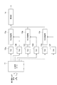
図1に示されるように、時間計測装置10は、計測用ゲート11(第1の切替部)と、TAC(Time-Analog-Converter)回路12(第1の時間振幅変換器)と、TAC制御部13と、制御部14と、基準用ゲート15(第2の切替部)と、TAC回路16(第2の時間振幅変換器)と、を備えている。より詳細には、時間計測装置10は、TAC回路12として複数のTAC回路12a〜12jを有し、TAC制御部13として複数のTAC制御部13a〜13fを有し、TAC回路16として複数のTAC回路16a,16bを有する。複数のTAC回路12a〜12jは計測用ゲート11に対して互いに並列に接続されており、複数のTAC回路16a,16bは基準用ゲート15に対して互いに並列に接続されている。なお、図1では、時間計測装置10の構成のうち、後述するデジタルカウンタ20(図3参照)の図示を省略している。当該デジタルカウンタ20は、TAC制御部13に設けられていてもよいし、TAC制御部13とは別に設けられていてもよい。
As shown in FIG. 1, the
TAC回路12は、第1のトリガ信号が入力されてから第2のトリガ信号が入力されるまでの時間差をアナログ信号(振幅)として出力する時間振幅変換器の回路である。TAC回路12は、例えば10nsの時間を計測可能に構成されている。TAC回路12は、具体的には、検出器4において検出された検出信号を第1のトリガ信号、クロック生成回路9(図3参照)から出力されたクロック信号を第2のトリガ信号として、検出信号及びクロック信号間の時間に応じたアナログ信号(振幅)を計測信号としてTAC制御部13に出力する。すなわち、TAC回路12は、検出器4において検出された検出信号、及び、クロック信号が入力され、検出信号及びクロック信号間の時間に応じた計測信号を出力する。TAC回路12は、計測用ゲート11を介して、検出信号の入力を受け付ける。
The
TAC制御部13は、TAC回路12から入力された計測信号であるアナログ信号(振幅)をデジタル信号に変換するADコンバータである。TAC制御部13は、AD変換後のデジタル信号を計測信号として制御部14に出力する。上述したように、時間計測装置10は、TAC制御部13として複数のTAC制御部13a〜13fを有している。図1に示されるように、TAC制御部13aはTAC回路12a,12bから計測信号の入力を受け付け、TAC制御部13bはTAC回路12c,12dから計測信号の入力を受け付け、TAC制御部13cはTAC回路12e,16aから計測信号の入力を受け付け、TAC制御部13dはTAC回路12f,12gから計測信号の入力を受け付け、TAC制御部13eはTAC回路12h,12iから計測信号の入力を受け付け、TAC制御部13fはTAC回路12j,16bから計測信号の入力を受け付ける。
The
計測用ゲート11は、検出器4から第1のトリガ信号である検出信号の入力を受け、該検出信号をTAC回路12に出力する。詳細には、計測用ゲート11は、検出器4から入力された検出信号を、複数のTAC回路12a〜12jのうち1つのTAC回路12にのみ出力する。図2及び図3は、マルチTAC計測を説明する図である。ここでのマルチTAC計測とは、複数のTAC回路12a〜12jを切り替えながら利用する計測手法をいう。
The
図2に示されるように、計測用ゲート11は、複数のTAC回路12a〜12jに1対1で対応するようにTAC回路12a〜12jの前段に設けられた複数のゲート回路11a〜11jを有する。計測用ゲート11の複数のゲート回路11a〜11jは、1つのみ有効(検出信号の入力を受け付ける状態)とされる。有効とされていないゲート回路11a〜11jは、待機状態(検出信号の入力を受け付けない状態)とされる。計測用ゲート11は、有効とされるゲート回路11a〜11jを切り替えることにより、複数のTAC回路12a〜12jのうち1つのみに検出信号が入力されるようにする。
As shown in FIG. 2, the
計測用ゲート11は、複数のTAC回路12a〜12jのデッドタイムを考慮して、検出信号が入力されるTAC回路12a〜12jを切り替える。ここでのデッドタイムとは、TAC回路12において時間が計測された後に一定の時間再度の時間計測が行えなくなる時間をいう。各TAC回路12a〜12jは、互いに同等の性能であり、デッドタイムも同程度である。なお、各TAC回路12a〜12jのデッドタイムは、互いに異なっていてもよい。例えば図2に示される例では、計測用ゲート11は、最初に、ゲート回路11aを有効とし、他のゲート回路11b〜11jを待機状態とする。この状態においては、検出器4から計測用ゲート11に検出信号が入力されると、ゲート回路11aにのみ検出信号が入力され、ゲート回路11aを介してTAC回路12aに検出信号が入力される。TAC回路12aでは、検出信号及びクロック信号間の時間に応じた計測信号が出力される。当該計測信号が出力される処理が行われた後一定の時間については、TAC回路12aにおいて再度の時間計測が行えないデッドタイムとなる。このため、計測用ゲート11は、2番目のゲート回路11bを有効とし、他のゲート回路11a,11c〜11jを待機状態とする。この状態においては、検出器4から計測用ゲート11に検出信号が入力されると、ゲート回路11bにのみ検出信号が入力され、ゲート回路11bを介してTAC回路12bに検出信号が入力される。そして、TAC回路12aと同様にTAC回路12bについてもデッドタイムとなるため、計測用ゲート11は、つづいて3番目のゲート回路11cを有効とし他のゲート回路11a,11b,11d〜11jを待機状態とする。このように、計測用ゲート11は、各TAC回路12a〜12jに対応するゲート回路11a〜11jを順番に1つのみ有効とすることにより、検出信号が入力されるTAC回路12a〜12jを順番に切り替える。この方式によれば、フォトンを取りこぼしてしまうデッドタイムは、TAC回路12のデッドタイム(TAC処理中デッドタイム)ではなく、ゲート回路11a〜11jの切り替え時間のみとなる。TAC処理中デッドタイムは例えば150nsであり、ゲート回路の切り替え時間は例えば1nsであるので、本方式により、フォトンを取りこぼしてしまうデッドタイムを大幅に短くすることができる。
The
計測用ゲート11は、デッドタイムを考慮して予め設定された切り替え情報に基づき、検出信号が入力されるTAC回路12a〜12jを切り替えている。当該切り替え情報は、デッドタイム中のTAC回路12a〜12jに検出信号が入力されないように、TAC回路12a〜12jの切り替えの順番(ゲート回路11a〜11jについて有効とする順番)を規定した情報である。すなわち、計測用ゲート11は、検出信号の入力先が、デッドタイム中ではないTAC回路12a〜12jになるように、TAC回路12a〜12jを切り替える。このような切り替えが可能になる前提として、複数のTAC回路12a〜12jは、TAC回路12のデッドタイムに応じた個数、設けられている。デッドタイムに応じた個数とは、各TAC回路12に順番に検出信号が入力されるようにTAC回路12の切り替えを行った際にデッドタイム中のTAC回路12に検出信号が入力されることとならない個数である。また、複数のTAC回路12a〜12jは、検出器4が検出する信号量に応じた個数、設けられている。検出器4が検出する信号量に応じた個数とは、想定される最大の信号量で検出信号が入力された場合であっても、各TAC回路12に順番に検出信号が入力されるようにTAC回路12の切り替えを行った際にデッドタイム中のTAC回路12に検出信号が入力されることとならない個数である。
The
制御部14は、デジタルカウンタ20(図3参照)から出力されたカウント信号とTAC回路12から出力されてTAC制御部13においてデジタル信号に変換された計測信号とに基づいて、検出器4によって検出された検出信号に係る時間情報を導出し出力する。図3に示されるように、デジタルカウンタ20は、検出器4からの検出信号とクロック生成回路9からのクロック信号とが入力されるカウンタである。デジタルカウンタ20は、クロック信号に同期して動作しており、クロック信号に応じて(クロック信号を数えて)カウント信号を制御部14に出力する。このようなデジタルカウンタ20は、検出信号について長時間計測を行うことができるものの、時間分解能を高くすることが難しい。制御部14は、デジタルカウンタ20による時間計測結果と、時間分解能が高いTAC回路12による時間計測結果とを組み合わせることにより、検出信号に係る時間情報の高時間分解且つ長時間計測を実現している。
The
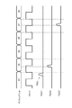
図4〜図6は、上述した時間情報の導出を説明する図である。図4〜図6において、横軸は時間軸を示している。図4に示されるように、デジタルカウンタ20は、クロック信号を数えてカウント信号を出力している。図4では、デジタルカウンタ20が、23、24、25、26、27、28を示すカウント信号を出力している例が示されている。上述したように、デジタルカウンタ20はクロック信号に同期して動作している。そして、図4に示されるように、いま、TAC回路12が、検出器4からの検出信号TRG1が入力されてから、検出信号TRG1の直後のクロック信号TRG2が入力されるまでの時間差Tを計測したとする。TAC回路12が出力する計測信号では、図5に示されるように、検出信号TRG1が入力されたタイミング(時間t1)から電圧(振幅)が検出信号TRG1に応じて増加を開始し、クロック信号TRG2が入力されたタイミング(時間t2)から電圧(振幅)がクロック信号TRG2に応じて一定となる。
4 to 6 are diagrams for explaining the derivation of the time information described above. In FIGS. 4 to 6, the horizontal axis indicates the time axis. As shown in FIG. 4, the
制御部14は、カウント信号が示すカウント値に応じた時間から、計測信号が示す時間を減算することによって、検出信号がTAC回路12に入力されるまでの時間を示す時間情報を導出している。すなわち、図4に示される例では、制御部14は、カウント信号が示すカウント値に応じた時間である23から、計測信号が示す時間情報である時間差Tを減算することによって、検出信号TRG1がTAC回路12に入力されるまでの時間を示す時間情報(23−T)を導出する。このような時間情報の導出は、デジタルカウンタ20に入力されるクロック信号と、TAC回路12に入力されるクロック信号とが対応している(TAC回路12に入力されたクロック信号が示すカウント値が一意に定まる)ことにより可能になるものである。
The
制御部14は、複数のTAC回路12が切り替えられる構成において、各TAC回路12からの情報に基づきそれぞれ時間情報を導出することにより、マルチフォトンの場合においても適切に時間計測を行うことができる。図6に示される例では、最初に検出信号が入力されるTAC回路12(図6においてTAC1と記載)の時間情報を導出した後に、2番目に検出信号が入力されるTAC回路12(図6においてTAC2と記載)の時間情報を導出し、さらに、3番目に検出信号が入力されるTAC回路12(図6においてTAC3と記載)の時間情報を導出している。すなわち、図6に示される例では、制御部14は、カウント信号が示すカウント値に応じた時間である23からTAC1が出力する計測信号が示す時間情報を減算することによりTAC1の計測結果に係る時間情報を導出し、カウント信号が示すカウント値に応じた時間である24からTAC2が出力する計測信号が示す時間情報を減算することによりTAC2の計測結果に係る時間情報を導出し、カウント信号が示すカウント値に応じた時間である27からTAC3が出力する計測信号が示す時間情報を減算することによりTAC3の計測結果に係る時間情報を導出している。制御部14は、導出した時間情報(計測結果)をコンピュータ5に出力する。
In a configuration in which a plurality of
TAC回路16は、第1のトリガ信号が入力されてから第2のトリガ信号が入力されるまでの時間差をアナログ信号(振幅)として出力する時間振幅変換器の回路である。TAC回路16は、検出器4において検出される検出信号に係る現象の同期信号に応じた信号を出力する。検出器4において検出される検出信号に係る現象とは、検出器4において検出される試料Sからの蛍光である。現象の同期信号とは、パルスジェネレータ2が光源3及び基準用ゲート15に同期した(例えば同一の)タイミングで出力したパルス信号に基づき基準用ゲート15がTAC回路16に出力する同期信号である。すなわち、ここでの同期信号とは、蛍光の検出に関して光源3から試料Sに照射される励起光に同期した信号である。TAC回路16は、具体的には、基準用ゲート15から入力された同期信号を第1のトリガ信号、クロック生成回路9から出力されたクロック信号を第2のトリガ信号として、同期信号及びクロック信号の時間差に応じたアナログ信号(振幅)を、上述した同期信号に応じた信号としてTAC制御部13に出力する。時間計測装置10は、TAC回路16として2つのTAC回路16a,16bを有する。TAC回路16aは、上述した同期信号に応じた信号をTAC制御部13cに出力する。また、TAC回路16bは、上述した同期信号に応じた信号をTAC制御部13fに出力する。TAC制御部13c,13fは、TAC回路16a,16bから入力された信号をデジタル信号に変換し制御部14に出力する。そして、制御部14は、上述した同期信号に応じた信号を更に考慮して、時間情報を導出してもよい。すなわち、制御部14は、上述した同期信号に応じた信号から、現象の開始タイミング(始点)を特定し、検出器4によって検出された検出信号に係る時間情報をより高精度に導出してもよい。
The
基準用ゲート15は、TAC回路16のデッドタイムを考慮して、上述した同期信号が入力されるTAC回路16a,16bを切り替える。基準用ゲート15は、パルスジェネレータ2からパルス信号の入力を受け、該パルス信号に応じた同期信号をTAC回路16a,16bのうち一方にのみ出力する。基準用ゲート15は、デッドタイムを考慮して予め設定された切り替え情報に基づき、同期信号が入力されるTAC回路16a,16bを切り替えている。当該切り替え情報は、デッドタイム中のTAC回路16a,16bに同期信号が入力されないように規定されている。
The
次に、本実施形態に係る時間計測装置10、及び、該時間計測装置10を備える蛍光寿命計測装置1の作用・効果について説明する。
Next, the action / effect of the
本実施形態に係る時間計測装置10は、クロック信号に応じてカウント信号を出力するデジタルカウンタ20と、検出器4において検出された検出信号、及び、クロック信号が入力され、検出信号及びクロック信号間の時間に応じた計測信号を出力する、複数のTAC回路12(TAC回路12a〜12j)と、デジタルカウンタ20から出力されたカウント信号とTAC回路12から出力された計測信号とに基づいて、検出信号に係る時間情報を導出し出力する制御部14と、TAC回路12のデッドタイムを考慮して、検出信号が入力されるTAC回路12を切り替える計測用ゲート11と、を備える。
In the
このような時間計測装置10では、検出信号及びクロック信号間の時間に応じた計測信号を出力するTAC回路12が、複数設けられている。そして、本時間計測装置10では、TAC回路12のデッドタイムが考慮されて、検出信号が入力されるTAC回路12の切り替えが実行される。例えば1つのTAC回路12のみで時間が計測される場合には、TAC回路12における計測後において再度の計測ができないデッドタイムが生じる。この点、TAC回路12が多段化されると共に、TAC回路12のデッドタイムが考慮されてTAC回路12が切り替えられることにより、計測後において再度の計測ができないTAC回路12から計測ができるTAC回路12に切り替えて、上述したデッドタイムを大幅に低減することができる。また、本実施形態に係るTAC回路12では、クロック信号に同期して動作するデジタルカウンタ20がカウント信号を出力することによりクロックの周波数に依存した大まかな時間計測(低時間分解且つ長時間計測)が行われると共に、TAC回路12が検出信号及びクロック信号間の時間に応じた計測信号を出力することによりデジタルカウンタ20の計測粗さを補う細かな時間計測(高時間分解且つ短時間計測)が行われる。これらの時間計測結果を合わせて最終的な時間情報が導出されることにより、高時間分解且つ長時間計測を実現することができる。以上のように、本実施形態に係る時間計測装置10によれば、デッドタイムを低減させて計測効率を向上させると共に、高時間分解且つ長時間計測を実現することができる。時間計測装置10による時間分解能の一例は0.25psであり、長時間計測の一例は24時間以上である。なお、ここでの時間分解能とは、計測単位であり、計測システム全体の時間分解能を示すものではない。
In such a
例えば、TADF等の有機EL発光材料を光励起した場合には、nsオーダの発光及びmsオーダの発光が生じうる。このように、非常に大きな時間単位差の減衰特性を有する発光が生じる場合には、蛍光寿命計測を効率よく行うには、高時間分解能を維持したまま長時間計測を行うことができる測定装置が必要となる。このような蛍光寿命計測等において、本実施形態に係る、高時間分解且つ長時間計測を実現する時間計測装置10を効果的に利用することができる。なお、時間計測装置10の計測対象は、上述したTADFに限られず、その他の蛍光体や、発光現象以外の様々な現象の対象を含みうる。
For example, when an organic EL light emitting material such as TADF is photoexcited, light emission on the order of ns and light emission on the order of ms can occur. In this way, when light emission with an attenuation characteristic with a very large time unit difference occurs, in order to efficiently measure the fluorescence lifetime, a measuring device capable of performing long-term measurement while maintaining high time resolution is required. You will need it. In such fluorescence lifetime measurement and the like, the
また、上述した時間計測装置10は、複数のTAC回路12を切り替えて時間計測を行うことによって、例えば蛍光寿命計測において、従来よりも高光量(例えば10倍程度の光量)での時間計測が可能になる。試料の発光強度が強い場合においては、従来はフィルタを用いて発光を大きく減衰して計測を行っており、信号のロスが多い状態で時間計測を行っているが、時間計測装置10によれば当該信号のロスを抑制した状態で高精度に時間計測を行うことができる。
Further, the
計測用ゲート11は、デッドタイムを考慮して予め設定された切り替え情報に基づき、TAC回路12を切り替えてもよい。このような構成によれば、予め設定された情報(デッドタイムを考慮した切り替え情報)に基づいて、容易且つ適切にTAC回路12を切り替えることができる。
The
制御部14は、カウント信号が示すカウント値に応じた時間から、計測信号が示す時間を減算することによって、検出信号が入力されるまでの時間を示す時間情報を導出してもよい。これにより、カウント信号及び計測信号に基づいて、検出信号が入力されるまでの時間を高精度に導出することができる。
The
計測用ゲート11は、デッドタイム中ではないTAC回路12に検出信号が入力されるように、TAC回路12を切り替えてもよい。これにより、TAC回路12のデッドタイムの影響により計測効率が悪化することを適切に回避できる。
The
複数のTAC回路12は、デッドタイムに応じた個数、設けられていてもよい。これにより、TAC回路12を切り替えることによってデッドタイムの影響を受けることを適切に回避できる。
The plurality of
複数のTAC回路12は、検出器4が検出する信号量に応じた個数、設けられていてもよい。これにより、信号量に応じた数だけTAC回路12が設けられることとなり、TAC回路12を切り替えることによってデッドタイムの影響を受けることを適切に回避できる。
The plurality of
時間計測装置10は、検出器4において検出される検出信号に係る現象の同期信号に応じた信号を出力する、複数のTAC回路16(TAC回路16a,16b)を更に備え、制御部14は、同期信号に応じた信号を更に考慮して、時間情報を導出してもよい。これにより、検出信号に係る現象の実際のタイミングを考慮して、検出信号に係る時間情報をより高精度に導出することができる。
The
時間計測装置10は、TAC回路16のデッドタイムを考慮して、同期信号が入力されるTAC回路16を切り替える基準用ゲート15を更に備えていてもよい。これにより、TAC回路16におけるデッドタイムの影響により基準信号の計測効率が悪化することを適切に回避できる。
The
本実施形態に係る蛍光寿命計測装置1は、試料Sから発せられる蛍光の寿命を計測する蛍光寿命計測装置であって、上述した時間計測装置10と、試料Sに生成した光を照射する光源3と、光源3からの光が照射された試料Sからの蛍光を検出し、検出信号を出力する検出器4と、光源3による光の出力を制御し、光源3及び時間計測装置10に互いに同期した同期信号を出力するパルスジェネレータ2と、を備える。このような蛍光寿命計測装置1によれば、上述した時間計測装置10を用いて、蛍光寿命を効率的に計測すると共に、蛍光寿命の計測について高時間分解且つ長時間計測を実現することができる。
The fluorescence
以上、本発明の一実施形態について説明したが、本発明は上記実施形態に限定されない。例えば、時間計測装置10が同期信号に係るTAC回路16及び基準用ゲート15を備えるとして説明したが、時間測定対象の現象のタイミング(繰り返しタイミング等)が把握できている場合には、図7に示されるように、TAC回路16及び基準用ゲート15を備えない構成が採用されてもよい。
Although one embodiment of the present invention has been described above, the present invention is not limited to the above embodiment. For example, it has been described that the
また、TAC回路12の数も実施形態において説明した数(8個)に限定されず、例えば図7に示されるように、TAC回路12が6個(TAC回路12a〜12f)等であってもよいし、その他の数であってもよい。このようなTAC回路12の適正な数は、例えば蛍光寿命計測であれば、測定する蛍光寿命値に応じて変化させることが好ましい。例えば、測定する蛍光寿命値が5μs以下である場合にはTAC回路12の数が8個(又はそれ以下)とされ、測定する蛍光寿命値が5μsよりも長い場合には9個以上のTAC回路12が設けられてもよい。
Further, the number of
1…蛍光寿命計測装置、2…パルスジェネレータ(信号生成部)、3…光源、4…検出器、10…時間計測装置、11…計測用ゲート(第1の切替部)、12…TAC回路(第1の時間振幅変換器)、14…制御部、15…基準用ゲート(第2の切替部)、16…TAC回路(第2の時間振幅変換器)、20…デジタルカウンタ(カウンタ)、S…試料(計測対象物)。 1 ... Fluorescent lifetime measuring device, 2 ... pulse generator (signal generator), 3 ... light source, 4 ... detector, 10 ... time measuring device, 11 ... measurement gate (first switching unit), 12 ... TAC circuit ( 1st time amplitude converter), 14 ... control unit, 15 ... reference gate (second switching unit), 16 ... TAC circuit (second time amplitude converter), 20 ... digital counter (counter), S … Sample (measurement target).
Claims (11)
検出器において検出された検出信号、及び、前記クロック信号が入力され、前記検出信号及び前記クロック信号間の時間に応じた計測信号を出力する、複数の第1の時間振幅変換器と、
前記カウンタから出力された前記カウント信号と前記第1の時間振幅変換器から出力された前記計測信号とに基づいて、前記検出信号に係る時間情報を導出し出力する制御部と、
前記第1の時間振幅変換器のデッドタイムを考慮して、前記検出信号が入力される前記第1の時間振幅変換器を切り替える第1の切替部と、を備える時間計測装置。A counter that outputs a count signal according to the clock signal,
A plurality of first time amplitude converters that input the detection signal detected by the detector and the clock signal and output a measurement signal according to the time between the detection signal and the clock signal.
A control unit that derives and outputs time information related to the detection signal based on the count signal output from the counter and the measurement signal output from the first time amplitude converter.
A time measuring device including a first switching unit for switching the first time amplitude converter into which the detection signal is input in consideration of the dead time of the first time amplitude converter.
前記制御部は、前記同期信号に応じた信号を更に考慮して、前記時間情報を導出する、請求項1〜6のいずれか一項記載の時間計測装置。A second time amplitude converter that outputs a signal corresponding to a synchronization signal of a phenomenon related to the detection signal detected by the detector is further provided.
The time measuring device according to any one of claims 1 to 6, wherein the control unit derives the time information in consideration of a signal corresponding to the synchronization signal.
前記第2の時間振幅変換器のデッドタイムを考慮して、前記同期信号が入力される前記第2の時間振幅変換器を切り替える第2の切替部を更に備える、請求項7記載の時間計測装置。It is equipped with a plurality of the above-mentioned second time amplitude converters.
The time measuring device according to claim 7, further comprising a second switching unit for switching the second time amplitude converter into which the synchronization signal is input in consideration of the dead time of the second time amplitude converter. ..
請求項1〜8のいずれか一項に記載された前記時間計測装置と、
前記計測対象物に生成した光を照射する光源と、
前記光源からの光が照射された前記計測対象物からの前記蛍光を検出し、前記検出信号を出力する前記検出器と、
前記光源による光の出力を制御し、前記光源及び前記時間計測装置に互いに同期した同期信号を出力する信号生成部と、を備える、蛍光寿命計測装置。It is a fluorescence life measuring device that measures the life of fluorescence emitted from the object to be measured.
The time measuring device according to any one of claims 1 to 8.
A light source that irradiates the light generated on the measurement object,
The detector that detects the fluorescence from the measurement object irradiated with the light from the light source and outputs the detection signal, and the detector.
A fluorescence lifetime measuring device including a signal generation unit that controls the output of light by the light source and outputs a synchronization signal synchronized with each other to the light source and the time measuring device.
前記複数の時間振幅変換器それぞれのデッドタイムに基づき、検出器において検出された検出信号が入力される一つの時間振幅変換器を選択する工程と、
選択した前記一つの時間振幅変換器に、前記検出信号及びクロック信号を入力し、前記検出信号及び前記クロック信号間の時間に応じた計測信号を得る工程と、
前記クロック信号に応じたカウント信号と前記計測信号とに基づき、前記検出信号に係る時間情報を導出し出力する工程と、を含む時間計測方法。It is a time measurement method implemented by a time measurement device that measures time while switching between multiple time amplitude converters.
Based on the dead time of each of the plurality of time amplitude converters, a step of selecting one time amplitude converter into which the detection signal detected by the detector is input, and
A step of inputting the detection signal and the clock signal to the one selected time amplitude converter and obtaining a measurement signal according to the time between the detection signal and the clock signal.
A time measurement method including a step of deriving and outputting time information related to the detection signal based on the count signal corresponding to the clock signal and the measurement signal.
Priority Applications (1)
| Application Number | Priority Date | Filing Date | Title |
|---|---|---|---|
| JP2021150175A JP2022031264A (en) | 2020-08-06 | 2021-09-15 | Time measurement device, fluorescence life-time measurement device, and time measurement method |
Applications Claiming Priority (3)
| Application Number | Priority Date | Filing Date | Title |
|---|---|---|---|
| JP2020133839 | 2020-08-06 | ||
| JP2020133839 | 2020-08-06 | ||
| PCT/JP2021/018263 WO2022030062A1 (en) | 2020-08-06 | 2021-05-13 | Time measuring device, fluorescence lifetime measuring device, and time measuring method |
Related Child Applications (1)
| Application Number | Title | Priority Date | Filing Date |
|---|---|---|---|
| JP2021150175A Division JP2022031264A (en) | 2020-08-06 | 2021-09-15 | Time measurement device, fluorescence life-time measurement device, and time measurement method |
Publications (2)
| Publication Number | Publication Date |
|---|---|
| JP6946599B1 true JP6946599B1 (en) | 2021-10-06 |
| JPWO2022030062A1 JPWO2022030062A1 (en) | 2022-02-10 |
Family
ID=77915227
Family Applications (2)
| Application Number | Title | Priority Date | Filing Date |
|---|---|---|---|
| JP2021541093A Active JP6946599B1 (en) | 2020-08-06 | 2021-05-13 | Time measuring device, fluorescence life measuring device, and time measuring method |
| JP2021150175A Pending JP2022031264A (en) | 2020-08-06 | 2021-09-15 | Time measurement device, fluorescence life-time measurement device, and time measurement method |
Family Applications After (1)
| Application Number | Title | Priority Date | Filing Date |
|---|---|---|---|
| JP2021150175A Pending JP2022031264A (en) | 2020-08-06 | 2021-09-15 | Time measurement device, fluorescence life-time measurement device, and time measurement method |
Country Status (5)
| Country | Link |
|---|---|
| US (1) | US20230288336A1 (en) |
| EP (1) | EP4170436A4 (en) |
| JP (2) | JP6946599B1 (en) |
| KR (1) | KR20230047328A (en) |
| CN (1) | CN115803689A (en) |
Family Cites Families (3)
| Publication number | Priority date | Publication date | Assignee | Title |
|---|---|---|---|---|
| US6690463B2 (en) | 2000-02-10 | 2004-02-10 | Evotec Biosystems Ag | Fluorescence intensity and lifetime distribution analysis |
| DE102007026684B4 (en) * | 2007-06-08 | 2009-03-19 | Gesellschaft für Schwerionenforschung mbH | Time-amplitude converter component |
| US10079608B2 (en) * | 2011-09-08 | 2018-09-18 | Fastree 3D Bv | Time-to-digital converter and method therefor |
-
2021
- 2021-05-13 EP EP21853056.6A patent/EP4170436A4/en active Pending
- 2021-05-13 KR KR1020227044160A patent/KR20230047328A/en not_active Application Discontinuation
- 2021-05-13 CN CN202180046560.9A patent/CN115803689A/en active Pending
- 2021-05-13 JP JP2021541093A patent/JP6946599B1/en active Active
- 2021-05-13 US US18/017,698 patent/US20230288336A1/en active Pending
- 2021-09-15 JP JP2021150175A patent/JP2022031264A/en active Pending
Also Published As
| Publication number | Publication date |
|---|---|
| US20230288336A1 (en) | 2023-09-14 |
| EP4170436A4 (en) | 2024-07-10 |
| JP2022031264A (en) | 2022-02-18 |
| CN115803689A (en) | 2023-03-14 |
| KR20230047328A (en) | 2023-04-07 |
| EP4170436A1 (en) | 2023-04-26 |
| JPWO2022030062A1 (en) | 2022-02-10 |
Similar Documents
| Publication | Publication Date | Title |
|---|---|---|
| US10962932B2 (en) | Time measurement device, time measurement method, light-emission-lifetime measurement device, and light-emission-lifetime measurement method | |
| Tremsin et al. | Optimization of Timepix count rate capabilities for the applications with a periodic input signal | |
| WO2018211801A1 (en) | Optical sensor and electronic device | |
| CN107272010B (en) | Distance sensor, distance measuring method thereof and 3D image sensor | |
| JP6946599B1 (en) | Time measuring device, fluorescence life measuring device, and time measuring method | |
| Lubsandorzhiev et al. | Studies of prepulses and late pulses in the 8 ″electron tubes series of photomultipliers | |
| WO2022030062A1 (en) | Time measuring device, fluorescence lifetime measuring device, and time measuring method | |
| Thomas et al. | Bunch purity measurement for Diamond | |
| WO2022030063A1 (en) | Time measurement device, fluorescence lifetime measurement device, and time measurement method | |
| Aiello et al. | Aging characterization on large area photo-multipliers | |
| Zhao et al. | Afterpulse measurement for 8-inch candidate PMTs for LHAASO | |
| JP4119886B2 (en) | Optical pulse tester | |
| Mizutani et al. | Time-between-photons method for measuring fluorescence lifetimes | |
| Giudicotti et al. | Characterization of fast microchannel plate photomultipliers for the ITER core LIDAR Thomson scattering system | |
| Giordano et al. | Noise and spurious pulses for Cherenkov light detection with 10-inch and 3-inch photomultipliers | |
| Torino et al. | Filling pattern measurements at ALBA using Time Correlated Single Photon Counting | |
| Sadik | Photon number resolving systems and instrumentation | |
| Gao et al. | Bunch Purity Measurement for SSRF | |
| JPS624659B2 (en) | ||
| JP2022031264A5 (en) | ||
| CN116147767A (en) | Transient spectrometer acquisition time measuring device and measuring method | |
| Antoranz Canales et al. | Testbench to characterize pixels of the Major Atmospheric Gamma-ray Imaging Cherenkov (MAGIC) telescope | |
| Balkanov et al. | Baikal-2 two-channel photomultiplier tube | |
| Lucarelli et al. | Testbench to characterize pixels of the Major Atmospheric Gamma-ray Imaging Cherenkov (MAGIC) telescope | |
| Thomas et al. | Time domain measurements at Diamond |
Legal Events
| Date | Code | Title | Description |
|---|---|---|---|
| A621 | Written request for application examination |
Free format text: JAPANESE INTERMEDIATE CODE: A621 Effective date: 20210715 |
|
| A871 | Explanation of circumstances concerning accelerated examination |
Free format text: JAPANESE INTERMEDIATE CODE: A871 Effective date: 20210715 |
|
| TRDD | Decision of grant or rejection written | ||
| A01 | Written decision to grant a patent or to grant a registration (utility model) |
Free format text: JAPANESE INTERMEDIATE CODE: A01 Effective date: 20210907 |
|
| A61 | First payment of annual fees (during grant procedure) |
Free format text: JAPANESE INTERMEDIATE CODE: A61 Effective date: 20210915 |
|
| R150 | Certificate of patent or registration of utility model |
Ref document number: 6946599 Country of ref document: JP Free format text: JAPANESE INTERMEDIATE CODE: R150 |
|
| R250 | Receipt of annual fees |
Free format text: JAPANESE INTERMEDIATE CODE: R250 |