JP6945064B2 - Fluid die with inlet and outlet channels - Google Patents
Fluid die with inlet and outlet channels Download PDFInfo
- Publication number
- JP6945064B2 JP6945064B2 JP2020514588A JP2020514588A JP6945064B2 JP 6945064 B2 JP6945064 B2 JP 6945064B2 JP 2020514588 A JP2020514588 A JP 2020514588A JP 2020514588 A JP2020514588 A JP 2020514588A JP 6945064 B2 JP6945064 B2 JP 6945064B2
- Authority
- JP
- Japan
- Prior art keywords
- fluid
- channel
- inlet
- outlet
- injection
- Prior art date
- Legal status (The legal status is an assumption and is not a legal conclusion. Google has not performed a legal analysis and makes no representation as to the accuracy of the status listed.)
- Active
Links
Images


Classifications
-
- B—PERFORMING OPERATIONS; TRANSPORTING
- B41—PRINTING; LINING MACHINES; TYPEWRITERS; STAMPS
- B41J—TYPEWRITERS; SELECTIVE PRINTING MECHANISMS, i.e. MECHANISMS PRINTING OTHERWISE THAN FROM A FORME; CORRECTION OF TYPOGRAPHICAL ERRORS
- B41J2/00—Typewriters or selective printing mechanisms characterised by the printing or marking process for which they are designed
- B41J2/005—Typewriters or selective printing mechanisms characterised by the printing or marking process for which they are designed characterised by bringing liquid or particles selectively into contact with a printing material
- B41J2/01—Ink jet
- B41J2/135—Nozzles
- B41J2/14—Structure thereof only for on-demand ink jet heads
- B41J2/14016—Structure of bubble jet print heads
- B41J2/14032—Structure of the pressure chamber
- B41J2/1404—Geometrical characteristics
-
- B—PERFORMING OPERATIONS; TRANSPORTING
- B41—PRINTING; LINING MACHINES; TYPEWRITERS; STAMPS
- B41J—TYPEWRITERS; SELECTIVE PRINTING MECHANISMS, i.e. MECHANISMS PRINTING OTHERWISE THAN FROM A FORME; CORRECTION OF TYPOGRAPHICAL ERRORS
- B41J2/00—Typewriters or selective printing mechanisms characterised by the printing or marking process for which they are designed
- B41J2/005—Typewriters or selective printing mechanisms characterised by the printing or marking process for which they are designed characterised by bringing liquid or particles selectively into contact with a printing material
- B41J2/01—Ink jet
- B41J2/015—Ink jet characterised by the jet generation process
- B41J2/04—Ink jet characterised by the jet generation process generating single droplets or particles on demand
- B41J2/045—Ink jet characterised by the jet generation process generating single droplets or particles on demand by pressure, e.g. electromechanical transducers
- B41J2/04501—Control methods or devices therefor, e.g. driver circuits, control circuits
- B41J2/0458—Control methods or devices therefor, e.g. driver circuits, control circuits controlling heads based on heating elements forming bubbles
-
- B—PERFORMING OPERATIONS; TRANSPORTING
- B41—PRINTING; LINING MACHINES; TYPEWRITERS; STAMPS
- B41J—TYPEWRITERS; SELECTIVE PRINTING MECHANISMS, i.e. MECHANISMS PRINTING OTHERWISE THAN FROM A FORME; CORRECTION OF TYPOGRAPHICAL ERRORS
- B41J2/00—Typewriters or selective printing mechanisms characterised by the printing or marking process for which they are designed
- B41J2/005—Typewriters or selective printing mechanisms characterised by the printing or marking process for which they are designed characterised by bringing liquid or particles selectively into contact with a printing material
- B41J2/01—Ink jet
- B41J2/135—Nozzles
- B41J2/14—Structure thereof only for on-demand ink jet heads
- B41J2/14016—Structure of bubble jet print heads
- B41J2/14145—Structure of the manifold
-
- B—PERFORMING OPERATIONS; TRANSPORTING
- B41—PRINTING; LINING MACHINES; TYPEWRITERS; STAMPS
- B41J—TYPEWRITERS; SELECTIVE PRINTING MECHANISMS, i.e. MECHANISMS PRINTING OTHERWISE THAN FROM A FORME; CORRECTION OF TYPOGRAPHICAL ERRORS
- B41J2/00—Typewriters or selective printing mechanisms characterised by the printing or marking process for which they are designed
- B41J2/005—Typewriters or selective printing mechanisms characterised by the printing or marking process for which they are designed characterised by bringing liquid or particles selectively into contact with a printing material
- B41J2/01—Ink jet
- B41J2/015—Ink jet characterised by the jet generation process
- B41J2/04—Ink jet characterised by the jet generation process generating single droplets or particles on demand
- B41J2/045—Ink jet characterised by the jet generation process generating single droplets or particles on demand by pressure, e.g. electromechanical transducers
- B41J2/04501—Control methods or devices therefor, e.g. driver circuits, control circuits
- B41J2/04543—Block driving
-
- B—PERFORMING OPERATIONS; TRANSPORTING
- B41—PRINTING; LINING MACHINES; TYPEWRITERS; STAMPS
- B41J—TYPEWRITERS; SELECTIVE PRINTING MECHANISMS, i.e. MECHANISMS PRINTING OTHERWISE THAN FROM A FORME; CORRECTION OF TYPOGRAPHICAL ERRORS
- B41J2/00—Typewriters or selective printing mechanisms characterised by the printing or marking process for which they are designed
- B41J2/005—Typewriters or selective printing mechanisms characterised by the printing or marking process for which they are designed characterised by bringing liquid or particles selectively into contact with a printing material
- B41J2/01—Ink jet
- B41J2/17—Ink jet characterised by ink handling
- B41J2/175—Ink supply systems ; Circuit parts therefor
-
- B—PERFORMING OPERATIONS; TRANSPORTING
- B41—PRINTING; LINING MACHINES; TYPEWRITERS; STAMPS
- B41J—TYPEWRITERS; SELECTIVE PRINTING MECHANISMS, i.e. MECHANISMS PRINTING OTHERWISE THAN FROM A FORME; CORRECTION OF TYPOGRAPHICAL ERRORS
- B41J2/00—Typewriters or selective printing mechanisms characterised by the printing or marking process for which they are designed
- B41J2/005—Typewriters or selective printing mechanisms characterised by the printing or marking process for which they are designed characterised by bringing liquid or particles selectively into contact with a printing material
- B41J2/01—Ink jet
- B41J2/135—Nozzles
- B41J2/14—Structure thereof only for on-demand ink jet heads
- B41J2002/14467—Multiple feed channels per ink chamber
-
- B—PERFORMING OPERATIONS; TRANSPORTING
- B41—PRINTING; LINING MACHINES; TYPEWRITERS; STAMPS
- B41J—TYPEWRITERS; SELECTIVE PRINTING MECHANISMS, i.e. MECHANISMS PRINTING OTHERWISE THAN FROM A FORME; CORRECTION OF TYPOGRAPHICAL ERRORS
- B41J2202/00—Embodiments of or processes related to ink-jet or thermal heads
- B41J2202/01—Embodiments of or processes related to ink-jet heads
- B41J2202/12—Embodiments of or processes related to ink-jet heads with ink circulating through the whole print head
Description
流体ダイは、流体を移動させる流体システムの構成要素である。流体ダイの一例は、いくつかの流体噴射ノズルを含む流体噴射ダイである。流体ダイ及び流体噴射ダイは、マイクロ再循環ポンプのような他の非噴射アクチュエータをさらに含む場合がある。これらのノズルとポンプによって、とりわけインクや融着剤のような液体が噴射され、若しくは移動される。例えば、ノズルは、ある量の流体を保持する噴射室を含み、噴射室を通る流体アクチュエータは、ノズルの開口部を通して流体を噴射するように動作する。 A fluid die is a component of a fluid system that moves a fluid. An example of a fluid die is a fluid injection die that includes several fluid injection nozzles. Fluid dies and fluid injection dies may further include other non-injection actuators such as micro recirculation pumps. These nozzles and pumps inject or move liquids, especially inks and coagulants. For example, the nozzle includes an injection chamber that holds a certain amount of fluid, and a fluid actuator that passes through the injection chamber operates to inject fluid through the opening of the nozzle.
添付の図面は、本明細書に記載された原理のさまざまな例を示しており、明細書の一部である。例示された例は、単に例示のために与えられ、特許請求の範囲を限定するものではない。
図面全体を通して、同一の参照符号は、類似しているが必ずしも同一ではない要素を示している。図は必ずしも縮尺どおりではなく、一部の部分のサイズは、図示した例をより明確に示すために誇張されている場合がある。また、図面は、説明と一致する例及び/又は実施形態を提供するが、説明が、図面で提供された例及び/又は実施形態に限定されることはない。 Throughout the drawing, the same reference numerals indicate elements that are similar but not necessarily the same. The figures are not necessarily to scale and the size of some parts may be exaggerated to show the illustrated example more clearly. The drawings also provide examples and / or embodiments that are consistent with the description, but the description is not limited to the examples and / or embodiments provided in the drawings.
[詳細な説明]
本明細書で使用される流体ダイは、少量の流体をポンプ輸送し、混合し、分析し、噴射するのに使用可能なさまざまなタイプの統合デバイスを表す場合がある。そのような流体ダイとしては、例えば、流体噴射ダイ、積層造形分配器構成要素、デジタル滴定構成要素、及び/又は、様々な体積の流体を選択的かつ制御可能に噴射するのに使用可能な他のそのようなデバイスが挙げられる。流体ダイの他の例としては、流体センサデバイス、ラボオンチップデバイス、並びに/あるいは、流体を分析及び/又は処理できる他のそのような装置が挙げられる。噴射ダイではない流体ダイでは、流体は、噴射されるのではなく、チャネルを通して、例えばライフサイエンスアプリケーションで分析され、若しくは他の方法で処理される。
[Detailed explanation]
The fluid dies used herein may represent different types of integrated devices that can be used to pump, mix, analyze, and inject small amounts of fluid. Such fluid dies include, for example, fluid injection dies, laminated build distributor components, digital titration components, and / or others that can be used to selectively and controlally inject fluids of varying volumes. Such devices are mentioned. Other examples of fluid dies include fluid sensor devices, lab-on-a-chip devices, and / or other such devices capable of analyzing and / or processing fluids. In fluid dies that are not jet dies, the fluid is not jetted, but is analyzed through channels, for example in life science applications, or otherwise processed.
具体例として、こうした流体ダイは、インクジェットプリンタ、多機能プリンタ(MFP)、及び積層造形装置のような任意数の印刷装置において見られる。これらの装置における流体システムは、少量の液体を正確かつ迅速に分配するために使用される。例えば、積層造形装置では、流体噴射システムが、融着剤を分配する。融着剤は、造形材料上に堆積され、そこで造形材料の硬化を促進し、三次元製品を形成する。 As a specific example, such fluid dies can be found in any number of printing devices such as inkjet printers, multifunction printers (MFPs), and layered builders. The fluid system in these devices is used to accurately and quickly distribute small amounts of liquid. For example, in a laminated molding system, a fluid injection system distributes the cohesive agent. The fusion agent is deposited on the modeling material, where it accelerates the curing of the modeling material and forms a three-dimensional product.
流体噴射システムによっては、インクを紙のような二次元印刷媒体上に分配するものがある。例えば、インクジェット印刷中に、流体は、流体噴射ダイに送られる。印刷する内容に応じて、その流体噴射ダイが配置されたデバイスは、インク滴を印刷媒体上に放出/噴射する時間と位置を決定する。このようにして、流体噴射ダイは、複数のインク滴を所定の領域上に放出することにより、印刷する画像内容の表現を作成する。紙の他に、他の形態の印刷媒体も使用される場合がある。したがって、先に説明したように、本明細書に記載されたシステム及び方法は、二次元印刷(すなわち、基板上に流体を堆積させること)の形で実施されてもよいし、、三次元印刷製品を形成するために、三次元印刷(すなわち、材料基材上に融着剤や他の機能性薬剤を堆積させること)の形で実施されてもよい。 Some fluid injection systems distribute the ink onto a two-dimensional print medium such as paper. For example, during inkjet printing, the fluid is fed to a fluid injection die. Depending on what is being printed, the device on which the fluid jet die is located determines the time and position at which the ink droplets are ejected / ejected onto the print medium. In this way, the fluid jet die creates a representation of the image content to be printed by ejecting a plurality of ink droplets onto a predetermined area. In addition to paper, other forms of print media may also be used. Thus, as described above, the systems and methods described herein may be implemented in the form of two-dimensional printing (ie, depositing fluid on a substrate), or three-dimensional printing. It may be carried out in the form of three-dimensional printing (ie, depositing a cohesive or other functional agent on the material substrate) to form the product.
そのような流体ダイ及び流体噴射ダイは、様々なタイプの流体の移動及び噴射の効率が向上しているが、それらの動作の強化により能力は向上する可能性がある。一例として、一部のアクチュエータの動作は、流体ダイを通過する流体の組成を変化させることがある。例えば、サーマルエジェクタは、印加電圧に応じて発熱する。サーマルエジェクタが発熱すると、噴射室内の流体の一部は気化し、泡を形成する。この泡により、流体は、開口部から印刷媒体上に押し出される。非噴射ダイ及び噴射ダイにおいて見られる非噴射アクチュエータも、同様に動作する。アクチュエータを何度も作動させた後、流体の一部は気化し、流体から水が枯渇することになる。言い換えれば、流体は、濃縮され、粘性が高くなる。水が枯渇した流体は、ノズルに悪影響を及ぼし、液体の品質を低下させる可能性がある。 Such fluid dies and fluid injection dies have improved efficiency in the movement and injection of various types of fluids, but their capabilities may be improved by enhancing their operation. As an example, the operation of some actuators may change the composition of the fluid passing through the fluid die. For example, the thermal ejector generates heat according to the applied voltage. When the thermal ejector generates heat, a part of the fluid in the injection chamber evaporates to form bubbles. The bubbles push the fluid out of the openings onto the print medium. Non-injection dies and non-injection actuators found in injection dies work similarly. After operating the actuator many times, part of the fluid vaporizes and the fluid is depleted of water. In other words, the fluid is concentrated and becomes more viscous. Water-depleted fluids can adversely affect the nozzles and reduce the quality of the liquid.
これは、一つには、流体をノズル及び/又は室に渡すように循環させることによって対処される。ただし、再循環機構の望ましい効果は、流体力学によって低下する。例えば、流体は、流体供給スロットを介して流体ダイに供給される。マクロ再循環システムは、これらの流体供給スロットを通して液体を駆動する外部ポンプを含む。流体ダイの幅が狭いため、このマクロ再循環流は、マイクロ再循環ループに引き込まれるほど流体供給スロットの深くまで浸透しない可能性がある。つまり、流体供給スロットによって、マクロ再循環流は、マイクロ再循環流から分離される。したがって、マイクロ再循環ループ内の流体は補充されず、代わりに、同じ量の流体が、ループを通して再循環される。ループを通して再循環された流体は、さまざまな作動サイクルにさらされるため、その品質が低下し、印刷及び/又は流体の特性に悪影響を及ぼす可能性がある。 This is addressed, in part, by circulating the fluid through the nozzle and / or chamber. However, the desired effect of the recirculation mechanism is diminished by hydrodynamics. For example, the fluid is fed to the fluid die via the fluid feed slot. The macro recirculation system includes an external pump that drives the liquid through these fluid supply slots. Due to the narrow width of the fluid die, this macro recirculation flow may not penetrate deep enough into the fluid supply slot to be drawn into the micro recirculation loop. That is, the fluid supply slot separates the macro recirculation flow from the micro recirculation flow. Therefore, the fluid in the micro-recirculation loop is not replenished and instead the same amount of fluid is recirculated through the loop. The fluid recirculated through the loop is exposed to various operating cycles, which can reduce its quality and adversely affect printing and / or fluid properties.
したがって、本明細書では、これら及び他の問題を解決する流体噴射ダイについて説明する。すなわち、本明細書は、流体噴射ダイに入る流れを強制的に横向きにするシステム及び方法を説明する。この例では、ダイスロットを、流体噴射ダイの背面のチャネルに連結された入口通路及び出口通路に置き換える。より具体的には、流体を噴射するノズルを、流体噴射ダイの前面に配置する。流体は、背面からそれらのノズルに供給される。閉鎖されたチャネルによって、流れを流体噴射ダイにより近付けることができる。すなわち、これらのチャネルがなければ、流体供給スロットにより流体噴射ダイの入口に供給される流体は、低速であり、マイクロ再循環ループに近づくには不十分である。この例では、流体がマイクロ流体ループの全体を通して循環されているが、流体が、液体供給源から補充されることはない。 Therefore, this specification describes a fluid injection die that solves these and other problems. That is, the present specification describes a system and method for forcing a flow entering a fluid injection die to be lateral. In this example, the die slot is replaced with an inlet and outlet passageway connected to a channel on the back of the fluid injection die. More specifically, the nozzle for injecting the fluid is arranged in front of the fluid injection die. Fluid is supplied to those nozzles from the back. The closed channel allows the flow to be closer to the fluid injection die. That is, without these channels, the fluid supplied by the fluid supply slot to the inlet of the fluid injection die is slow and insufficient to approach the microrecirculation loop. In this example, the fluid is circulated throughout the microfluidic loop, but the fluid is not replenished from the liquid source.
これらのチャネルによれば、流体力学によってマイクロ再循環ループの近くの流れが増加され、マイクロ再循環ループに新しい流体が補充されるようになる。すなわち、マイクロ再循環流が、チャネルを通って移動するマクロ再循環流から流体を引き出したり、流体をマクロ再循環流の中に噴射したりするようになる。したがって、この例では、マイクロ再循環ループとノズルに、新しい新鮮な(未使用の)流体が供給される。 According to these channels, fluid dynamics increase the flow near the micro-recirculation loop, allowing the micro-recirculation loop to be replenished with new fluid. That is, the micro-recirculation flow draws fluid from the macro-recirculation flow moving through the channel and injects the fluid into the macro-recirculation flow. Therefore, in this example, the microrecirculation loop and nozzle are fed with fresh (unused) fluid.
すなわち、マイクロ再循環流は、二次的な流れと渦を作り出す脈動の形で、通路に流体を引き込んだり、通路から外に流体を噴射したりする。これらの渦は、通路から一定の距離だけ離れている。チャネルは、マクロ再循環流をこれらの渦に直接引き込み、マクロ再循環する流体が十分な流速でこれらの渦と相互作用し、マクロ再循環する流体とマイクロ再循環ループ内の流体との混合が、加速されるようにする。マクロ再循環する流体をマイクロ再循環ループに近づけるこれらのチャネルがなければ、マクロ再循環する流体は、マイクロ再循環ループの入口/出口付近の渦と相互作用するだけの十分な速度で流体供給スロットに到達しない。この流れの増加により、冷却も強化される。なぜなら、新鮮なインクは、消耗した流体、すなわちリサイクルされた流体よりも、効率的に流体ダイから熱を引き出すからである。 That is, the micro-recirculation flow draws fluid into and out of the passage in the form of pulsations that create secondary flows and vortices. These vortices are separated from the passage by a certain distance. The channel draws the macro-recirculating flow directly into these vortices, the macro-recirculating fluid interacts with these vortices at a sufficient flow rate, and the mixing of the macro-recirculating fluid with the fluid in the micro-recirculating loop , To be accelerated. Bringing macro-recirculating fluid closer to the micro-recirculation loop Without these channels, the macro-recirculating fluid would be fast enough to interact with the vortices near the inlet / outlet of the micro-recirculation loop. Does not reach. This increase in flow also enhances cooling. This is because fresh ink draws heat from the fluid die more efficiently than the depleted fluid, the recycled fluid.
流体がマイクロ再循環ループで効率的に補充された場合であっても、マイクロ再循環ループから外に出てくる廃流体は、新鮮な流体が送られてくるもとの流体チャネルと同じ流体チャネルに投入される可能性がある。つまり、廃流体は、液体供給スロット内の新鮮な液体と混ざる可能性がある。廃流体と新鮮な液体の混合により、ノズルに供給される新鮮な流体の品質は、低下する可能性がある。 Even if the fluid is efficiently replenished in the micro-recirculation loop, the waste fluid coming out of the micro-recirculation loop is the same fluid channel as the original fluid channel from which the fresh fluid was sent. May be thrown into. That is, the waste fluid can mix with the fresh liquid in the liquid supply slot. Mixing of waste fluid and fresh liquid can reduce the quality of the fresh fluid supplied to the nozzle.
したがって、本明細書は、この問題に対処するダイ及びシステムを記載している。具体的には、本明細書によれば、ノズルに向かう入口通路は、入口チャネルと整列され、廃流体は、出口通路を通して出口チャネルに受け渡される。すなわち、ノズルに流体を供給するチャネルは、ノズルから廃流体を受け取るチャネルから分離される。ノズルに供給された流体をノズルから出る廃流体から分離することにより、印刷媒体のような表面に堆積させるためのより高品質な流体を、ノズルで利用することが可能となる。 Therefore, this specification describes dies and systems that address this issue. Specifically, according to the present specification, the inlet passage to the nozzle is aligned with the inlet channel, and the waste fluid is passed to the outlet channel through the outlet passage. That is, the channel that supplies the fluid to the nozzle is separated from the channel that receives the waste fluid from the nozzle. By separating the fluid supplied to the nozzles from the waste fluid exiting the nozzles, higher quality fluids for depositing on surfaces such as print media can be used in the nozzles.
具体的には、本明細書は、流体噴射ダイを記載している。流体噴射ダイは、ある量の流体を噴射するためのノズルのアレイを含む。各ノズルは、ある量の流体を保持する噴射室と;前記ある量の流体を分配するための開口部と;前記噴射室内に配置され、前記ある量の流体を前記開口部を通して噴射する流体アクチュエータとを含む。各ノズルは、基板に形成され、前記噴射室内に流体を配送する入口通路と、前記基板に形成され、前記噴射室から外に流体を配送する出口通路とをさらに含む。流体噴射ダイは、前記基板の背面に形成され、入口チャネルと出口チャネルとに分割されたチャネルのアレイをさらに含む。各入口チャネルが、各自の複数の入口通路に流体的に接続され、各出口チャネルが、各自の複数の出口通路に流体的に接続される。 Specifically, this specification describes a fluid injection die. The fluid injection die includes an array of nozzles for injecting a certain amount of fluid. Each nozzle has an injection chamber that holds a certain amount of fluid; an opening for distributing the certain amount of fluid; and a fluid actuator that is arranged in the injection chamber and injects the certain amount of fluid through the opening. And include. Each nozzle further includes an inlet passage formed in the substrate to deliver the fluid into the injection chamber and an outlet passage formed in the substrate to deliver the fluid out of the injection chamber. The fluid injection die further includes an array of channels formed on the back surface of the substrate and divided into inlet and outlet channels. Each inlet channel is fluidly connected to its own plurality of inlet passages, and each exit channel is fluidly connected to its own plurality of outlet passages.
本明細書は、印刷流体カートリッジも記載している。印刷流体カートリッジは、ハウジングと、前記ハウジング内に配置され、基板上に堆積される流体を収容するリザーバとを含む。このカートリッジは、ハウジング上に配置された流体噴射ダイのアレイをさらに含む。各流体噴射ダイは、ある量の流体を噴射するためのノズルのアレイを含む。各ノズルは、ある量の流体を保持する噴射室と;前記ある量の流体を分配するための開口部と;前記噴射室内に配置され、前記ある量の流体を前記開口部を通して噴射する流体アクチュエータとを含む。各ノズルは、基板に形成され、前記噴射室内に流体を配送する入口通路と、前記基板に形成され、前記噴射室から外に流体を配送する出口通路とをさらに含む。流体噴射ダイは、前記基板の背面に形成され、入口チャネルと出口チャネルとに分割されたチャネルのアレイをさらに含む。各入口チャネルが、各自の複数の入口通路に流体的に接続され、各出口チャネルが、各自の複数の出口通路に流体的に接続される。 The present specification also describes a printing fluid cartridge. The printing fluid cartridge includes a housing and a reservoir that is located within the housing and contains fluid that is deposited on the substrate. The cartridge further includes an array of fluid injection dies placed on the housing. Each fluid injection die contains an array of nozzles for injecting a certain amount of fluid. Each nozzle has an injection chamber that holds a certain amount of fluid; an opening for distributing the certain amount of fluid; and a fluid actuator that is arranged in the injection chamber and injects the certain amount of fluid through the opening. And include. Each nozzle further includes an inlet passage formed in the substrate to deliver the fluid into the injection chamber and an outlet passage formed in the substrate to deliver the fluid out of the injection chamber. The fluid injection die further includes an array of channels formed on the back surface of the substrate and divided into inlet and outlet channels. Each inlet channel is fluidly connected to its own plurality of inlet passages, and each exit channel is fluidly connected to its own plurality of outlet passages.
本明細書は、流体噴射ダイを製造する方法も記載している。この方法によれば、ノズル及び対応する通路のアレイであって、前記通路を通して流体が噴射される、ノズル及び対応する通路のアレイを形成する。基板上にチャネルのアレイを形成される。チャネルのアレイは、入口チャネルと出口チャネルとを含む。次に、各入口チャネルが、各自の複数の入口通路に流体的に接続され、各出口チャネルが、各自の複数の出口通路に流体的に接続されるように、前記ノズル及び通路のアレイを、チャネルのアレイに結合する。 The specification also describes how to make a fluid injection die. According to this method, an array of nozzles and corresponding passages is formed in which fluid is injected through the passages to form an array of nozzles and corresponding passages. An array of channels is formed on the substrate. The array of channels includes an inlet channel and an exit channel. An array of nozzles and passages is then provided such that each inlet channel is fluidly connected to its own plurality of inlet passages and each outlet channel is fluidly connected to its own plurality of outlet passages. Join to an array of channels.
要約すると、このような流体噴射ダイを使用することで、1)流体中の水分濃度を維持することによって流体粘度の影響を軽減し、2)ノズル内のより効率的なマイクロ再循環を促進し、3)ノズルの健全性を改善し、4)流体噴射ダイの近くで流体の混合を行うことにより、印刷品質を向上させ、5)流体噴射ダイを対流によって冷却し、6)流体噴射ダイから気泡を除去し、7)ノズルの再プライミングを可能にし、8)廃インクを新鮮なインクから分離することにより印刷品質を改善することができる。ただし、本明細書に開示される装置は、いくつかの技術分野において他の問題及び欠陥にも対処できると考えられる。 In summary, the use of such fluid injection dies 1) reduces the effects of fluid viscosity by maintaining the water concentration in the fluid and 2) promotes more efficient microrecirculation in the nozzle. 3) Improve nozzle integrity, 4) improve print quality by mixing fluid near the fluid injection die, 5) cool the fluid injection die by convection, 6) from the fluid injection die Print quality can be improved by removing air bubbles, 7) allowing nozzle repriming, and 8) separating waste ink from fresh ink. However, the devices disclosed herein are believed to be able to address other problems and deficiencies in some technical areas.
本明細書及び添付の特許請求の範囲で使用される「アクチュエータ」という用語は、ノズル、又は別の非噴射アクチュエータを指している。例えば、アクチュエータであるノズルは、流体噴射ダイから流体を噴射するように動作する。非噴射アクチュエータの例である再循環ポンプは、流体噴射ダイ内の通路、チャネル、及び経路を通して流体を移動させる。 As used herein and in the appended claims, the term "actuator" refers to a nozzle, or another non-injection actuator. For example, a nozzle, which is an actuator, operates to inject fluid from a fluid injection die. A recirculation pump, which is an example of a non-injection actuator, moves fluid through passages, channels, and paths within a fluid injection die.
したがって、本明細書及び添付の特許請求の範囲で使用される「ノズル」という用語は、流体を表面上に分配する流体噴射ダイの個々の構成要素を指している。ノズルは、少なくとも噴射室、エジェクタ流体アクチュエータ、及びノズル開口部を含む。 Thus, as used herein and in the appended claims, the term "nozzle" refers to the individual components of a fluid injection die that distributes fluid over a surface. The nozzle includes at least an injection chamber, an ejector fluid actuator, and a nozzle opening.
さらに、本明細書及び添付の特許請求の範囲で使用される「印刷流体カートリッジ」という用語は、印刷媒体上へのインク又は他の流体の噴射に使用されるデバイスを指す場合がある。一般に、印刷流体カートリッジは、インク、ワックス、ポリマー又は他の流体のような流体を分配する流体噴射装置であってよい。プリンタカートリッジは、流体噴射ダイを含む場合がある。一部の例では、プリンタカートリッジは、プリンタ、グラフィックプロッター、コピー機、及びファクシミリで使用される場合がある。これらの例では、流体噴射ダイは、インク又は他の流体を紙のような媒体上に噴射することにより、所望の画像を形成することができる。 In addition, as used herein and in the appended claims, the term "printing fluid cartridge" may refer to a device used to inject ink or other fluid onto a printing medium. In general, the printing fluid cartridge may be a fluid injector that dispenses a fluid such as ink, wax, polymer or other fluid. The printer cartridge may include a fluid injection die. In some examples, printer cartridges may be used in printers, graphic plotters, copiers, and facsimiles. In these examples, the fluid injection die can form the desired image by injecting ink or other fluid onto a medium such as paper.
さらに、本明細書及び添付の特許請求の範囲で使用される「いくつかの」という用語又はこれに類する用語は、1から無限大までを含む任意の正の数として広く理解されることを意味する。 In addition, the terms "some" or similar as used herein and in the appended claims are meant to be broadly understood as any positive number, including from 1 to infinity. do.
以下の説明では、説明の目的で、本システム及び方法の完全な理解を提供するために、多数の特定の詳細が記載される。しかしながら、当業者には明らかであるように、本装置、システム、及び方法は、それらの特定の詳細なしで実施されてもよい。本明細書で「例」又はこれに類する語が記載されている場合、これは、その例に関して説明された特定の機能、構造、又は性質が、記載どおりに含まれているが、一部の例において、含まれていても含まれていなくてもよいことを意味する。 In the following description, a number of specific details are provided for purposes of illustration to provide a complete understanding of the system and methods. However, as will be apparent to those skilled in the art, the device, systems, and methods may be implemented without their specific details. Where "examples" or similar terms are mentioned herein, this includes, as described, the particular function, structure, or property described for that example, but in part. In the example, it means that it may or may not be included.
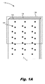
次に図面を参照すると、図1Aは、本明細書に記載された原理の一例による、入口及び出口チャネルを備えた流体噴射ダイ(100)の図である。上述のように、流体噴射ダイ(100)は、印刷流体を基板上に堆積させる際に使用される印刷システムの構成要素を指している。流体噴射ダイ(100)は、ノズル開口部、噴射室、及び作動エジェクタを含む流体ダイの一例である。これに比べて、非噴射流体ダイは、作動エジェクタ及びノズル開口部を含まなくてもよいが、代わりに、流体を受け取る流体室、及び中に配置されたセンサを含む場合がある。非噴射流体ダイ及び流体噴射ダイは、本明細書に記載された入口及び出口通路、入口及び出口チャネル、並びに流体供給スロットのような、類似する他の構成要素を有する場合がある。印刷流体を基板上に噴射するために、流体噴射ダイ(100)は、ノズルのアレイを含む。流体は、ノズルの開口部(102)を通して、流体噴射ダイから排出される。図1Aでは、単純化のために、1つのノズル開口部(102)が、参照符号で示されている。また、ノズル開口部(102)と流体噴射ダイ(100)の相対的サイズは、一定の縮尺ではなく、説明のためにノズルが拡大されていることに留意されたい。 Next, with reference to the drawings, FIG. 1A is a diagram of a fluid injection die (100) with inlet and outlet channels according to an example of the principles described herein. As mentioned above, the fluid injection die (100) refers to the components of the printing system used to deposit the printing fluid on the substrate. The fluid injection die (100) is an example of a fluid die including a nozzle opening, an injection chamber, and an actuating ejector. In comparison, the non-injection fluid die may not include an actuating ejector and nozzle opening, but instead may include a fluid chamber that receives the fluid and a sensor located therein. Non-injection fluid dies and fluid injection dies may have other similar components such as inlet and outlet passages, inlet and outlet channels, and fluid supply slots as described herein. The fluid injection die (100) includes an array of nozzles to inject the printing fluid onto the substrate. The fluid is discharged from the fluid injection die through the nozzle opening (102). In FIG. 1A, for simplicity, one nozzle opening (102) is indicated by a reference numeral. Also note that the relative size of the nozzle opening (102) and the fluid injection die (100) is not a constant scale, but the nozzle is enlarged for illustration purposes.
流体噴射ダイ(100)のノズル開口部(102)は、列又はアレイを成すように配置され、流体噴射ダイ(100)と印刷媒体とが互いに対して移動する際に、ノズル開口部(102)からの流体の適当な順序の噴射により、文字、記号、及び/又は他のグラフィックス若しくは画像を、印刷媒体上に印刷するように構成される。 The nozzle openings (102) of the fluid injection die (100) are arranged in a row or array so that the nozzle openings (102) move as the fluid injection die (100) and the print medium move relative to each other. Letters, symbols, and / or other graphics or images are configured to be printed on the printing medium by a proper order of injection of fluid from.
一例では、アレイ内のノズルは、さらにグループ化される場合がある。例えば、アレイのノズルの第1のサブセットは、ある色のインク、又は一組の流体特性を有する一種類の流体に関係する一方、アレイのノズルの第2のサブセットは、別の色のインク、又は別の一組の流体特性を有する流体に関係する場合がある。 In one example, the nozzles in the array may be further grouped. For example, a first subset of array nozzles involves an ink of one color, or one type of fluid with a set of fluid properties, while a second subset of array nozzles is an ink of another color. Or it may be related to a fluid having another set of fluid properties.
流体噴射ダイ(100)は、ノズル開口部(102)から流体を噴射する際に流体噴射ダイ(100)を制御するコントローラに結合される場合がある。例えば、コントローラは、印刷媒体上に文字、記号、及び/又は他のグラフィックス若しくは画像を形成する噴射流体滴のパターンを定義する。噴射流体滴のパターンは、計算装置から受信した印刷ジョブコマンド及び/又はコマンドパラメタによって決定される。 The fluid injection die (100) may be coupled to a controller that controls the fluid injection die (100) when injecting fluid through the nozzle opening (102). For example, the controller defines a pattern of jet fluid droplets that form letters, symbols, and / or other graphics or images on the print medium. The pattern of the jet fluid droplets is determined by the print job command and / or command parameters received from the calculator.
流体噴射ダイ(100)は、様々な層から形成される場合がある。例えば、ノズル基板(104)には、ノズルの噴射室及び開口部(102)が画定される場合がある。ノズル基板(104)は、SU−8又は他の材料から形成される場合がある。流体噴射ダイ(100)は、種々のチャネル及び流体入口/出口が画定されたチャネル基板(106)をさらに含む。流体入口/出口通路は、噴射室との間で相互に流体を受け渡し、流体チャネルは、流体供給スロットから流体入口/出口通路へのマクロフローを導く。チャネル基板(106)は、シリコンから形成される場合がある。 The fluid injection die (100) may be formed from various layers. For example, the nozzle substrate (104) may have a nozzle injection chamber and an opening (102) defined. Nozzle substrate (104) may be formed from SU-8 or other materials. The fluid injection die (100) further includes a channel substrate (106) in which various channels and fluid inlets / outlets are defined. The fluid inlet / outlet passages pass fluids to and from the injection chamber, and the fluid channels guide the macroflow from the fluid supply slots to the fluid inlet / outlet passages. The channel substrate (106) may be made of silicon.
図1B及び図1Cは、本明細書に記載された原理の一例による、入口及び出口チャネルを備えた非噴射流体ダイ(101)の図である。具体的には、図1Bは、流体ダイ(101)の平面図であり、図1Cは、図1Bにおける「A」線に沿った断面図である。上記のように、流体ダイ(101)は、流体噴射ダイ(図1A、100)に類似しているが、流体ダイ(101)は、流体を噴射しないため、ノズル開口部(図1A、102)を含まない。 1B and 1C are views of a non-injection fluid die (101) with inlet and outlet channels according to an example of the principles described herein. Specifically, FIG. 1B is a plan view of the fluid die (101), and FIG. 1C is a cross-sectional view taken along the line “A” in FIG. 1B. As described above, the fluid die (101) is similar to the fluid injection die (FIGS. 1A, 100), but the fluid die (101) does not inject fluid, so the nozzle opening (FIGS. 1A, 102). Does not include.
流体噴射ダイ(100)と同様に、非噴射流体ダイ(101)は、様々な層から形成される場合がある。例えば、基板(104)には、流体室(103−1、103−2)が画定される場合がある。基板(104)は、SU−8又は他の材料から形成される場合がある。流体ダイ(101)は、種々のチャネル及び流体入口/出口が画定されたチャネル基板(106)をさらに含む。流体入口/出口通路は、流体室(103)との間で相互に流体を受け渡し、流体チャネルは、流体供給スロットから流体入口/出口通路へのマクロフローを導く。チャネル基板(106)は、シリコンから形成される場合がある。 Like the fluid injection die (100), the non-injection fluid die (101) may be formed from various layers. For example, a fluid chamber (103-1, 103-2) may be defined on the substrate (104). Substrate (104) may be formed from SU-8 or other materials. The fluid die (101) further includes a channel substrate (106) with various channels and fluid inlets / outlets defined. The fluid inlet / outlet passages pass fluid to and from the fluid chamber (103), and the fluid channels guide the macroflow from the fluid supply slot to the fluid inlet / outlet passages. The channel substrate (106) may be made of silicon.
図1Cは、チャネル(212、210)及び通路(216、218)を通る流体の流れを明確に示している。図示のように、通路(216、218)を通る流体の流れは、チャネル(212、210)を通る流体の流れに対して垂直である。すなわち、流体が入口チャネル(212)を通って流れる際に、流体は入口通路(216)を通って流体室(103)に導かれるため、流体の流れの方向は、垂直に変化される。チャネル(210、212)及び通路(216、218)を通る流体の流れは、図1Cに矢印で示されている。一部の例において、流体室(103)は、センサ(105−1、105−2)を含む場合がある。センサ(105−1、105−2)又は他の構成要素は、そこを通過する流体を分析し、又は他の方法で処理することができる。 FIG. 1C clearly shows the flow of fluid through channels (212, 210) and passages (216, 218). As shown, the flow of fluid through the passages (216, 218) is perpendicular to the flow of fluid through the channels (212, 210). That is, when the fluid flows through the inlet channel (212), the fluid is guided through the inlet passage (216) to the fluid chamber (103), so that the direction of the fluid flow is changed vertically. The flow of fluid through the channels (210, 212) and passages (216, 218) is indicated by arrows in FIG. 1C. In some examples, the fluid chamber (103) may include sensors (105-1, 105-2). Sensors (105-1, 105-2) or other components can analyze the fluid passing through it or otherwise process it.
一部の例において、流体ダイ(101)は、マイクロチャネルを含む場合がある。マイクロチャネルは、対応する流体室(103)との間で相互に流体を導く。そのようなマイクロチャネルは、少量の流体(例えば、ピコリットル規模、ナノリットル規模、マイクロリットル規模、ミリリットル規模)の流体の輸送が容易になるように、十分に小さなサイズ(例えば、ナノメートルサイズの規模、マイクロメートルサイズの規模、ミリメートルサイズの規模など)を有する場合がある。この例では、マイクロチャネルと通路(216、218)が、マイクロ再循環ループを形成している。一部の例では、ポンプ流体アクチュエータ(432−1、432−2)をチャネル内に配置することにより、流体室(103)との間で相互に流体を移動させる。そのようなマイクロチャネルは、そこを通過する流体の沈殿を防止し、流体室(103)内で新鮮な流体を利用できるようにする。流体アクチュエータは、静電膜アクチュエータ、機械的/衝撃駆動膜アクチュエータ、又は磁歪駆動アクチュエータであってもよく、あるいは、電気的作動に応答して流体の移動を引き起こすことができる他のそのような要素であってもよい。 In some examples, the fluid die (101) may include microchannels. The microchannel guides the fluid to and from the corresponding fluid chamber (103). Such microchannels are small enough in size (eg, nanometer-sized) to facilitate the transport of small amounts of fluid (eg, picolitre, nanoliter, microliter, milliliter). May have scale, micrometer size scale, milliliter size scale, etc.). In this example, the microchannels and passages (216, 218) form a microrecirculation loop. In some examples, pump fluid actuators (432-1, 432-2) are placed in the channel to move fluid to and from the fluid chamber (103). Such microchannels prevent the settling of fluid passing through it and make fresh fluid available within the fluid chamber (103). The fluid actuator may be an electrostatic membrane actuator, a mechanical / impact driven membrane actuator, or a magnetostrictive driven actuator, or other such element capable of inducing fluid movement in response to electrical action. It may be.
さらに、流体室(103)に流体を配送する入口通路(216)は、入口チャネル(212)から流体を受け取る。入口チャネル(212)は、流体室(103)及び作動ポンプ(432)を既に通過した流体を受け取る出口チャネル(210)から分離されている。図1Cに示されているように、一部の例において、異なる入口チャネル(212−2、212−3)から流体を受け取る流体室(103)は、廃流体を、異なる出口通路(218−1、218−2)によってではあるが、共用出口チャネル(210−2)に受け渡すことができる。 Further, the inlet passage (216) delivering the fluid to the fluid chamber (103) receives the fluid from the inlet channel (212). The inlet channel (212) is separated from the fluid chamber (103) and the outlet channel (210) that receives the fluid that has already passed through the actuating pump (432). As shown in FIG. 1C, in some examples, fluid chambers (103) that receive fluid from different inlet channels (212-2, 212-3) allow waste fluid to flow through different outlet passages (218-1). , 218-2), but can be passed to the shared exit channel (210-2).
図2A及び図2Bは、本明細書に記載された原理の一例による、入口及び出口チャネルを備えた流体噴射ダイ(図1A、100)のチャネル基板(106)の図である。具体的には、図2Aは、チャネル基板(106)の上面よりも上にある構成要素を破線で示したチャネル基板(106)の図である。図2Bは、チャネル基板(106)の底面側にある構成要素を破線で示したチャネル基板(106)の図である。図2Aにおいて、これらの破線の構成要素には、ノズル開口部(102)と、マイクロ再循環ポンプ(220)とが含まれる。マイクロ再循環ポンプ(220)は、マイクロ再循環ループを通して流体を移動するために使用される。マイクロ再循環ポンプ(220)は、ノズル基板(図1A、104)とチャネル基板(106)との間に配置される場合がある。単純化のために、ノズル開口部(102)及びマイクロ再循環ポンプ(220)の各々の1つのインスタンスが、参照符号で示されている。 2A and 2B are views of the channel substrate (106) of a fluid injection die (FIGS. 1A, 100) with inlet and outlet channels according to an example of the principles described herein. Specifically, FIG. 2A is a diagram of the channel substrate (106) in which the components above the upper surface of the channel substrate (106) are shown by broken lines. FIG. 2B is a diagram of the channel substrate (106) in which the components on the bottom surface side of the channel substrate (106) are shown by broken lines. In FIG. 2A, these dashed components include a nozzle opening (102) and a micro-recirculation pump (220). The micro recirculation pump (220) is used to move the fluid through the micro recirculation loop. The micro recirculation pump (220) may be arranged between the nozzle substrate (FIGS. 1A, 104) and the channel substrate (106). For simplicity, each one instance of the nozzle opening (102) and the micro-recirculation pump (220) is indicated by a reference numeral.
図2A及び図2Bでは、チャネル(210、212)、リブ(214)、及び通路(216、218)を含むノズルの種々の構成要素を示すために、ノズル基板(図1A、104)は、取り外されている。単純化のために、図2A及び図2Bにおける各構成要素の1つ又はいくつかのインスタンスが、参照符号で示されている。 In FIGS. 2A and 2B, the nozzle substrate (FIGS. 1A, 104) is removed to show the various components of the nozzle, including channels (210, 212), ribs (214), and passages (216, 218). It has been. For simplicity, one or several instances of each component in FIGS. 2A and 2B are indicated by reference numerals.
流体噴射ダイ(図1A、100)は、チャネル基板(106)に形成された通路(216、218)のアレイをさらに含む。上記のように、通路(216、218)のほんのいくつかのインスタンスが、参照符号で示されている。通路(216、218)は、対応する噴射室との間で相互に流体を配送する。具体的には、入口通路(216)は、入口チャネル(212)からノズルの噴射室へ流体を配送し、出口通路(218)は、噴射室から出口チャネル(210)へ流体を配送する。使用時には、流体は、入口通路(216)からマイクロ再循環ループに入り、そこでノズルによって使用され、その後、出口通路(218)から出る。入口通路を通る流体の流れは、図2A及び図2Bに矢印(222)で示されている。 The fluid injection die (FIGS. 1A, 100) further includes an array of passages (216, 218) formed in the channel substrate (106). As mentioned above, only a few instances of passages (216, 218) are indicated by reference numerals. The passages (216, 218) deliver fluid to and from the corresponding injection chambers. Specifically, the inlet passage (216) delivers the fluid from the inlet channel (212) to the nozzle injection chamber, and the outlet passage (218) delivers the fluid from the injection chamber to the outlet channel (210). In use, the fluid enters the microrecirculation loop through the inlet passage (216), where it is used by the nozzle and then exits the outlet passage (218). The flow of fluid through the inlet passage is indicated by an arrow (222) in FIGS. 2A and 2B.
一部の例において、通路(216、218)は、チャネル基板(106)の有孔膜に形成される場合がある。例えば、チャネル基板(106)は、シリコンから形成される場合があり、通路(216、218)は、チャネル基板(106)の一部を形成する穿孔シリコン膜から形成される場合がある。つまり、膜には孔が開けられている場合があり、膜がノズル基板(図1A、104)と結合されたときに、孔は、噴射室と整列され、噴射プロセスの際の流体の出入りの経路を形成することができる。図2Aに示されているように、2つの通路、すなわち、入口通路(216)と出口通路(218)は、各噴射室に対応する場合がある。一部の例において、通路は、丸穴であっても、角の丸い四角穴であってもよく、あるいは、他の種類の通路であってもよい。 In some examples, the passages (216, 218) may be formed in the perforated membrane of the channel substrate (106). For example, the channel substrate (106) may be formed from silicon, and the passages (216, 218) may be formed from a perforated silicon film that forms part of the channel substrate (106). That is, the membrane may be perforated, and when the membrane is coupled to the nozzle substrate (FIGS. 1A, 104), the pores are aligned with the injection chamber to allow fluid to enter and exit during the injection process. A route can be formed. As shown in FIG. 2A, the two passages, namely the inlet passage (216) and the outlet passage (218), may correspond to each injection chamber. In some examples, the passage may be a round hole, a square hole with rounded corners, or another type of passage.
次に、図2Bに移ると、流体噴射ダイ(図1A、100)は、チャネル(210、212)のアレイをさらに含む。チャネル(210、212)は、破線で示されているように、チャネル基板(106)の背面に形成されている。言い換えれば、図4に明確に示されているように、通路(216、218)は、チャネル基板(106)の上面上に形成され、チャネル基板(106)の背面に形成されたチャネル(212、210)と流体的に接続されている。 Next, moving to FIG. 2B, the fluid injection die (FIGS. 1A, 100) further includes an array of channels (210, 212). The channels (210, 212) are formed on the back surface of the channel substrate (106), as shown by the dashed line. In other words, as clearly shown in FIG. 4, the passages (216, 218) are formed on the top surface of the channel substrate (106) and on the back surface of the channel substrate (106). It is fluidly connected to 210).
チャネル(210、212)は、通路(216、218)との間で相互に流体を配送する。チャネル(210、212)は、複数の入口通路(216)に流体的に接続された入口チャネル(212)と、複数の出口通路(218)に流体的に接続された出口チャネル(210)とに分割されている。すなわち、流体は、入口チャネル(212)及び入口通路(216)を介してノズルに入り、出口通路(218)及び出口チャネル(210)を介して出る。こうすることで、出口通路(218)から出る廃流体が、入口通路(218)を介してノズルに入らないようにすることができる。 The channels (210, 212) deliver fluid to and from the passages (216, 218). The channels (210, 212) are divided into an inlet channel (212) fluidly connected to the plurality of inlet passages (216) and an outlet channel (210) fluidly connected to the plurality of outlet passages (218). It is divided. That is, the fluid enters the nozzle through the inlet channel (212) and the inlet passage (216) and exits through the outlet passage (218) and the outlet channel (210). By doing so, the waste fluid leaving the outlet passage (218) can be prevented from entering the nozzle through the inlet passage (218).
一部の例では、新鮮な流体が、入口チャネル(212)と出口チャネル(210)との両方に入る。入口チャネル(212)の場合、この流体の一部は、入口通路(216)に受け渡され、余分な新鮮な流体は、例えば共用出口流体供給スロットを通って、入口チャネル(212)から出る。出口チャネル(210)の場合、新鮮な流体は、出口チャネル(210)に受け渡されるが、入口通路(216)が出口チャネル(210)に結合されていないため、何れの入口通路(216)にも入らない。この新鮮な流体は、さらに、共用出口流体供給スロットを通って、出口チャネル(210)から出る。すなわち、入口チャネル(212)及び出口チャネル(210)は、共用入口流体供給スロット及び共用出口流体供給スロットにそれぞれ多岐連結されている。ただし、出口通路に連結されている出口チャネル(210)は、余分な新鮮な流体だけでなく、廃流体も、共用出口供給スロットに排出する。 In some examples, fresh fluid enters both the inlet channel (212) and the outlet channel (210). In the case of the inlet channel (212), a portion of this fluid is passed to the inlet passage (216) and excess fresh fluid exits the inlet channel (212), for example through a common outlet fluid supply slot. In the case of the outlet channel (210), the fresh fluid is passed to the outlet channel (210), but to any inlet passage (216) because the inlet passage (216) is not coupled to the outlet channel (210). Does not enter. This fresh fluid also exits the outlet channel (210) through a common outlet fluid supply slot. That is, the inlet channel (212) and the outlet channel (210) are variously connected to the common inlet fluid supply slot and the common outlet fluid supply slot, respectively. However, the outlet channel (210) connected to the outlet passage drains not only excess fresh fluid but also waste fluid into the common outlet supply slot.
チャネル(210、212)に戻ると、チャネル(210、212)は、任意数の表面によって画定される。例えば、チャネル(210、212)の1つの表面は、通路(216、218)が形成されたチャネル基板(106)の膜部分によって画定される。もう1つの表面は、スロット付きキャップ基板によって画定されてもよく、残りの表面は、リブ(214)によって画定される。 Returning to the channel (210, 212), the channel (210, 212) is defined by any number of surfaces. For example, one surface of the channel (210, 212) is defined by the membrane portion of the channel substrate (106) on which the passages (216, 218) are formed. The other surface may be defined by a slotted cap substrate and the remaining surface is defined by ribs (214).
これらのチャネル(210、212)によれば、流体噴射ダイ(図1A、100)を通る流体の流れの増加が促進される。例えば、チャネル(210、212)がなければ、流体は、流体噴射ダイ(図1A、100)の背面側を通る流体は、ノズルを通過する流体と十分に混合されるほど十分に通路(216、218)の近くを通ることができない。しかしながら、チャネル(210、212)は、流体をノズルの近くに引き込み、それによって、より大きな流体混合を促進する。流体の流れが増加することで、使用済みの流体がノズルから除去されるため、ノズルの健全性も改善される。使用済みの流体がノズル全体に再循環されると、噴射性能の低下や品質低下をもたらし、場合によっては、噴射障害をもたらす可能性がある。 These channels (210, 212) facilitate an increase in fluid flow through the fluid injection die (FIGS. 1A, 100). For example, in the absence of channels (210, 212), the fluid would pass through the back side of the fluid injection die (FIGS. 1A, 100) sufficiently through the passage (216, Cannot pass near 218). However, the channels (210, 212) draw the fluid closer to the nozzle, thereby facilitating greater fluid mixing. Increased fluid flow removes used fluid from the nozzle, which also improves nozzle integrity. Recirculation of used fluid throughout the nozzle can result in poor injection performance, poor quality and, in some cases, injection failure.
一部の例において、各入口チャネル(212)は、一対の出口チャネル(210)の間に配置される。例えば、第1の入口チャネル(212−1)は、第1の出口チャネル(210−1)と第2の出口チャネル(210−2)との間に配置される。特定の一例では、特定の入口チャネル(212)に結合された隣り合う入口通路(216)が、特定の入口チャネル(212)の両側の出口チャネル(210)に流体的に接続される。例えば、第2の入口チャネル(212−2)に流体的に接続された1つの入口通路(216−1)は、第2の出口チャネル(210−2)に流体的に接続された出口通路(218−1)に対応する場合があり、第2の入口チャネル(212−2)に流体的に接続されたもう1つの入口通路(216−3)は、第3の出口チャネル(210−3)に流体的に接続された出口通路(218−3)に対応する場合がある。 In some examples, each inlet channel (212) is located between a pair of exit channels (210). For example, the first inlet channel (212-1) is arranged between the first exit channel (210-1) and the second exit channel (210-2). In a particular example, adjacent inlet passages (216) coupled to a particular inlet channel (212) are fluidly connected to exit channels (210) on either side of the particular inlet channel (212). For example, one inlet passage (216-1) fluidly connected to the second inlet channel (212-2) is a fluidly connected outlet passage (210-2) to the second outlet channel (210-2). The other inlet passage (216-3), which may correspond to 218-1) and is fluidly connected to the second inlet channel (212-2), is the third exit channel (210-3). May correspond to an outlet passage (218-3) fluidly connected to the.
例えば入口チャネル(212)及び出口チャネル(210)により廃流体を新鮮な流体から分離することによって、関連する印刷装置の性能が向上する。例えば、廃流体が入口通路(216)に流れ込まないようにすることで、廃流体の有害な性質、すなわち熱の増加や粘度の増加が、入口通路(216)に入る流体に影響を及ぼすことがなくなる。図2Bに示した例では、各チャネル、すなわち、入口チャネル(212)と出口チャネル(210)の両方が、流体供給スロットから流体を受け取る。次に、流体は、各入口チャネル(212)及び出口チャネル(210)を出るが、このとき、出口チャネル(212)から出る流体は、そこに供給された新鮮な流体の他に、ノズルから排出された廃流体を含む点で相違する。混合された流体は、図2Bに一点鎖線で示されている。 Separation of waste fluid from fresh fluid, for example by inlet channels (212) and outlet channels (210), improves the performance of the associated printing equipment. For example, by preventing the waste fluid from flowing into the inlet passage (216), the harmful properties of the waste fluid, namely increased heat and increased viscosity, can affect the fluid entering the inlet passage (216). It disappears. In the example shown in FIG. 2B, each channel, i.e. both the inlet channel (212) and the outlet channel (210), receives fluid from the fluid supply slot. The fluid then exits each inlet channel (212) and outlet channel (210), at which time the fluid exiting the outlet channel (212) is discharged from the nozzle in addition to the fresh fluid supplied therein. It differs in that it contains waste fluid that has been removed. The mixed fluid is shown as an alternate long and short dash line in FIG. 2B.
図3は、本明細書に記載された原理の一例による、入口及び出口チャネル(210、212)を備えた流体噴射ダイ(図1A、100)の底面図である。具体的には、図3は、スロット付きキャップ基板(307)と、流体が流れるチャネル(212、210)が画定されたチャネル基板(106)の背面とを示している。図3は、ノズル開口部(図1A、102)が形成されたノズル基板(104)の底面も示している。図3は、チャネル(212、210)を画定するリブ(214)も示している。単純化のために、図3では、多くの構成要素の単一のインスタンスが、参照符号で示されている。 FIG. 3 is a bottom view of a fluid injection die (FIGS. 1A, 100) with inlet and outlet channels (210, 212) according to an example of the principles described herein. Specifically, FIG. 3 shows a cap substrate with slots (307) and a back surface of a channel substrate (106) in which fluid flow channels (212, 210) are defined. FIG. 3 also shows the bottom surface of the nozzle substrate (104) in which the nozzle openings (FIGS. 1A, 102) are formed. FIG. 3 also shows ribs (214) defining channels (212, 210). For simplicity, in FIG. 3, a single instance of many components is indicated by a reference code.
図3は、流体供給スロット(326−1、328−2)も示している。流体供給スロット(326−1、328−2)は、様々なチャネル(210、212)との間で相互に流体を供給する。流体供給スロット(326)は、スロット付きキャップ基板(307)に形成され、流体をチャネル(212、210)に供給する。上記のように、チャネル(212、210)の各々に入る流体は、同じであってよく、すなわち、新鮮な流体であってよい。ただし、作動ポンプ及びエジェクタによる作動後、出口チャネル(210)から外に出てくる流体は、廃流体と混合される可能性がある。新鮮な流体と廃流体の混合された流体は、図3に一点鎖線で示されている。 FIG. 3 also shows fluid supply slots (326-1, 328-2). Fluid supply slots (326-1, 328-2) supply fluid to each other with various channels (210, 212). The fluid supply slot (326) is formed in the slotted cap substrate (307) to supply the fluid to the channels (212, 210). As mentioned above, the fluid entering each of the channels (212, 210) may be the same, i.e. a fresh fluid. However, the fluid coming out of the outlet channel (210) after actuation by the actuating pump and ejector may be mixed with the waste fluid. A mixed fluid of fresh fluid and waste fluid is shown by the alternate long and short dash line in FIG.
図4は、本明細書に記載された原理の一例による、入口及び出口チャネル(210、212)を備えた流体噴射ダイ(100)の断面図である。図4は、チャネル(212、210)及び通路(216、218)を通る流体の流れを明確に示している。図示のように、通路(216、218)を通る流体の流れは、チャネル(212、210)を通る流体の流れに対して垂直である。すなわち、流体が入口チャネル(212)を通って流れる際に、流体は入口通路(216)を通ってノズルに導かれるため、流体の流れの方向は、垂直に変化される。チャネル(210、212)及び通路(216、218)を通る流体の流れは、図4に矢印で示されている。 FIG. 4 is a cross-sectional view of a fluid injection die (100) with inlet and outlet channels (210, 212) according to an example of the principles described herein. FIG. 4 clearly shows the flow of fluid through the channels (212, 210) and passages (216, 218). As shown, the flow of fluid through the passages (216, 218) is perpendicular to the flow of fluid through the channels (212, 210). That is, when the fluid flows through the inlet channel (212), the fluid is guided to the nozzle through the inlet passage (216), so that the direction of the fluid flow is changed vertically. The flow of fluid through the channels (210, 212) and passages (216, 218) is indicated by arrows in FIG.
図4は、とりわけ、アレイのノズルを示している。単純化のために、図4では、1つのノズルの種々の構成要素が、参照符号で示されている。流体を噴射するために、ノズルは、いくつかの構成要素を含む。例えば、ノズルは、噴射されるある量の流体を保持する噴射室(428)と、前記ある量の流体が開口部(102)を通して噴射される開口部(102)と、噴射室(428)内に配置され、前記ある量の流体を開口部(102)を通して噴射する噴射流体アクチュエータ(430)とを含む。噴射室(428)及びノズル開口部(102)は、チャネル基板(図1A、106)の上に堆積されたノズル基板(104)に画定される場合がある。 FIG. 4 shows, among other things, the nozzles of the array. For simplicity, the various components of one nozzle are indicated by reference numerals in FIG. To inject the fluid, the nozzle contains several components. For example, the nozzle has an injection chamber (428) that holds a certain amount of fluid to be injected, an opening (102) in which the certain amount of fluid is injected through the opening (102), and an injection chamber (428). Includes an injection fluid actuator (430) that is arranged in and ejects the amount of fluid through the opening (102). The injection chamber (428) and nozzle opening (102) may be defined by a nozzle substrate (104) deposited on a channel substrate (FIGS. 1A, 106).
噴射アクチュエータ(430)に目を向けると、噴射流体アクチュエータ(430)は、発射抵抗器若しくは他の熱デバイス、又は圧電素子、あるいは、噴射室(428)から流体を噴射するための他の機構を含む場合がある。例えば、エジェクタ(430)は、発射抵抗器であってもよい。発射抵抗器は、印加電圧に応答して発熱する。発射抵抗器が発熱すると、噴射室(428)内の流体の一部は気化し、泡を形成する。この泡により、流体は、開口部(102)から印刷媒体上に押し出される。気化した流体の泡が破裂すると、流体は、通路(216)から噴射室(428)に引き込まれ、このプロセスが繰り返される。この例では、流体噴射ダイ(100)は、サーマルインクジェット(TIJ)流体噴射ダイ(100)であってもよい。 Turning to the injection actuator (430), the injection fluid actuator (430) provides a firing resistor or other thermal device, or a piezoelectric element, or other mechanism for injecting fluid from the injection chamber (428). May include. For example, the ejector (430) may be a firing resistor. The firing resistor generates heat in response to the applied voltage. When the firing resistor generates heat, a part of the fluid in the injection chamber (428) vaporizes to form bubbles. The bubbles push the fluid out of the opening (102) onto the print medium. When the vaporized fluid bubbles burst, the fluid is drawn from the passage (216) into the injection chamber (428) and this process is repeated. In this example, the fluid injection die (100) may be a thermal inkjet (TIJ) fluid injection die (100).
別の例では、噴射流体アクチュエータ(430)は、圧電デバイスであってもよい。電圧が印加されると、圧電デバイスは、その形状を変化させ、噴射室(428)内に圧力パルスを生成する。この圧力パルスは、流体を開口部(102)から印刷媒体上に押し出す。この例では、流体噴射ダイ(100)は、圧電インクジェット(PIJ)流体噴射ダイ(100)であってもよい。 In another example, the injection fluid actuator (430) may be a piezoelectric device. When a voltage is applied, the piezoelectric device changes its shape and creates a pressure pulse in the injection chamber (428). This pressure pulse pushes the fluid through the opening (102) onto the print medium. In this example, the fluid injection die (100) may be a piezoelectric inkjet (PIJ) fluid injection die (100).
一部の例において、各ノズルは、噴射流体アクチュエータ(430)、噴射室(428)及び開口部(102)の他に、マイクロチャネルを含む場合がある。マイクロチャネルは、対応する噴射室(428)との間で相互に流体を導く。そのようなマイクロチャネルは、少量の流体(例えば、ピコリットル規模、ナノリットル規模、マイクロリットル規模、ミリリットル規模)の流体の輸送が容易になるように、十分に小さなサイズ(例えば、ナノメートルサイズの規模、マイクロメートルサイズの規模、ミリメートルサイズの規模など)を有する場合がある。この例では、ノズルに対応するマイクロチャネルと通路(216、218)が、マイクロ再循環ループを形成している。一部の例では、ポンプ流体アクチュエータ(432−1、432−2)をチャネル内に配置することにより、噴射室(428)との間で相互に流体を移動させる。そのようなマイクロチャネルは、そこを通過する流体の沈殿を防止し、開口部(102)を通した噴射に備えて、新鮮な流体を利用可能にする。流体アクチュエータ、すなわち、エジェクタ(430)とポンプアクチュエータ(432)は両方とも、静電膜アクチュエータ、機械的/衝撃駆動膜アクチュエータ、又は磁歪駆動アクチュエータであってもよく、あるいは、電気的作動に応答して流体の移動を引き起こすことができる他のそのような要素であってもよい。 In some examples, each nozzle may include a microchannel in addition to the injection fluid actuator (430), injection chamber (428) and opening (102). The microchannel guides the fluid to and from the corresponding injection chamber (428). Such microchannels are small enough in size (eg, nanometer-sized) to facilitate the transport of small amounts of fluid (eg, picolitre, nanoliter, microliter, milliliter). May have scale, micrometer size scale, milliliter size scale, etc.). In this example, the microchannels and passages (216, 218) corresponding to the nozzles form a microrecirculation loop. In some examples, pump fluid actuators (432-1, 432-2) are placed in the channel to move fluid to and from the injection chamber (428). Such microchannels prevent the fluid from settling through it and make fresh fluid available for injection through the opening (102). The fluid actuators, i.e. the ejector (430) and the pump actuator (432), may both be electrostatic membrane actuators, mechanical / impact driven membrane actuators, or magnetostrictive driven actuators, or in response to electrical action. It may be another such element that can cause the movement of the fluid.
上記のように、そのようなマイクロ再循環ループによれば、新鮮な流体を噴射室(428)に提供することができ、したがってノズルの有効寿命を延ばすことができる。これは、新鮮な流体が提供されたときに、ノズルが最も良好に動作するからである。 As mentioned above, such a micro-recirculation loop can provide fresh fluid to the injection chamber (428) and thus extend the effective life of the nozzle. This is because the nozzle works best when fresh fluid is provided.
さらに、上記のように、噴射室(428)に流体を配送する入口通路(216)は、入口チャネル(212)から流体を受け取る。入口チャネル(212)は、ノズル及び作動ポンプ(432)を既に通過した流体を受け取る出口チャネル(210)から分離されている。図4に示されているように、一部の例において、異なる入口チャネル(212−2、212−3)から流体を受け取るノズルは、廃流体を、異なる出口通路(218−1、218−2)によってではあるが、共用出口チャネル(210−2)に受け渡すことができる。 Further, as described above, the inlet passage (216) delivering the fluid to the injection chamber (428) receives the fluid from the inlet channel (212). The inlet channel (212) is separated from the outlet channel (210) that receives the fluid that has already passed through the nozzle and actuating pump (432). As shown in FIG. 4, in some examples, nozzles that receive fluid from different inlet channels (212-2, 212-3) allow waste fluid to pass through different outlet passages (218-1, 218-2). ), But it can be passed to the shared exit channel (210-2).
図5は、本明細書に記載された原理の一例による、入口及び出口チャネル(図2B、210、212)を備えた流体噴射ダイ(100)を含む印刷流体カートリッジ(534)のブロック図である。印刷流体カートリッジ(534)は、印刷システム内で、流体を噴射するために使用される。一部の例では、印刷流体カートリッジ(534)は、例えば交換可能なカートリッジ(534)として、システムから取り外し可能である場合がある。一部の例では、印刷流体カートリッジ(534)は、基板幅のプリントバーであり、流体噴射ダイ(100)のアレイは、複数の流体噴射装置にグループ化され、流体噴射装置は、流体が堆積される基板の幅にわたって、互いに重ならないようにずらして配置されている。 FIG. 5 is a block diagram of a printing fluid cartridge (534) including a fluid injection die (100) with inlet and outlet channels (FIGS. 2B, 210, 212) according to an example of the principles described herein. .. The printing fluid cartridge (534) is used to inject fluid within the printing system. In some examples, the printing fluid cartridge (534) may be removable from the system, eg, as a replaceable cartridge (534). In some examples, the printing fluid cartridge (534) is a substrate-wide print bar, an array of fluid injection dies (100) is grouped into multiple fluid injection devices, and the fluid injection device deposits fluid. They are staggered over the width of the substrate so that they do not overlap each other.
印刷流体カートリッジ(534)は、印刷流体カートリッジ(534)の構成要素を収容するハウジング(536)を含む。ハウジング(536)は、ある量の流体を流体噴射ダイ(100)に供給するための流体リザーバ(538)を収容している。一般に、流体は、リザーバ(538)と流体噴射ダイ(100)との間を流れる。一部の例では、流体噴射ダイ(100)に供給された流体の一部は、動作中に消費され、印刷中に消費されなかった流体は、流体リザーバ(538)に戻される。一部の例では、流体は、インクであってよい。特定の一例では、インクは、とりわけ、水性紫外線(UV)インク、薬液、又は3D印刷材料であってもよい。 The printing fluid cartridge (534) includes a housing (536) that houses the components of the printing fluid cartridge (534). The housing (536) houses a fluid reservoir (538) for supplying a certain amount of fluid to the fluid injection die (100). Generally, the fluid flows between the reservoir (538) and the fluid injection die (100). In some examples, some of the fluid fed to the fluid injection die (100) is consumed during operation and the fluid not consumed during printing is returned to the fluid reservoir (538). In some examples, the fluid may be ink. In a particular example, the ink may be, among other things, an aqueous ultraviolet (UV) ink, a chemical solution, or a 3D printing material.
図6は、本明細書に記載された原理の一例による、入口及び出口チャネル(図2B、210、212)を備えた流体噴射ダイ(図1A、100)を形成する方法(600)のフロー図である。方法(600)に従って、ノズル及び通路(図2A、216、218)のアレイを形成する(ブロック601)。一部の例では、通路(図2A、216、218)は、穿孔シリコン膜の一部であってもよい。ノズル、又はむしろ、ノズルの開口部(図1A、102)及び噴射室(図4、428)は、SU−8のようなノズル基板(図1A、104)から形成されてもよい。したがって、ノズル及び通路(図2A、216、218)のアレイを形成すること(ブロック601)は、有孔シリコン膜をSU−8のノズル基板(図1A、104)と結合することを含む場合がある。 FIG. 6 is a flow diagram of a method (600) of forming a fluid injection die (FIGS. 1A, 100) with inlet and outlet channels (FIGS. 2B, 210, 212) according to an example of the principles described herein. Is. An array of nozzles and passages (FIGS. 2A, 216, 218) is formed according to method (600) (block 601). In some examples, the passages (FIGS. 2A, 216, 218) may be part of the perforated silicone membrane. The nozzle, or rather the nozzle opening (FIGS. 1A, 102) and the injection chamber (FIGS. 4, 428), may be formed from a nozzle substrate (FIGS. 1A, 104) such as SU-8. Therefore, forming an array of nozzles and passages (FIGS. 2A, 216, 218) (block 601) may include coupling a perforated silicon film with a SU-8 nozzle substrate (FIGS. 1A, 104). be.
次に、入口及び出口チャネル(図2B、210、212)を形成する(ブロック602)。入口及び出口チャネル(図2B、210、212)を形成すること(ブロック602)は、通路(図2A、216、218)が形成された膜の背面に、リブ(図2B、214)を接着することを含む場合がある。別の例では、この形成(ブロック602)は、チャネル基板(図1A、106)をエッチングすることにより、入口及び出口チャネル(図2A、210、212)を部分的に画定するリブ(図2B、214)を形成することを含む場合がある。 Next, inlet and outlet channels (FIGS. 2B, 210, 212) are formed (block 602). Forming the inlet and outlet channels (FIGS. 2B, 210, 212) (block 602) adheres ribs (FIGS. 2B, 214) to the back surface of the membrane in which the passages (FIGS. 2A, 216, 218) are formed. May include that. In another example, this formation (block 602) is a rib (FIG. 2B, FIG. 2B, which partially defines the inlet and outlet channels (FIGS. 2A, 210, 212) by etching the channel substrate (FIGS. 1A, 106). It may include forming 214).
入口及び出口チャネル(図2B、210、212)が形成され、ノズル及び通路(図2B、210、212)が形成された後、両者を結合し(ブロック603)、入口及び出口チャネル(図2B、210、212)を備えた流体噴射ダイ(図1A、100)を形成する。具体的には、各入口チャネル(図2B、212)が、各自の複数の入口通路(図2A、216)に流体的に接続され、各出口チャネル(図2B、210)が、各自の複数の出口通路(図2A、218)に流動的に接続されるように、両者を結合する。 After the inlet and outlet channels (FIGS. 2B, 210, 212) are formed and the nozzles and passages (FIGS. 2B, 210, 212) are formed, they are joined together (block 603) and the inlet and outlet channels (FIG. 2B, A fluid injection die (FIGS. 1A, 100) with 210, 212) is formed. Specifically, each inlet channel (FIGS. 2B, 212) is fluidly connected to its own plurality of inlet passages (FIGS. 2A, 216), and each exit channel (FIG. 2B, 210) is connected to its own plurality of inlet passages (FIGS. 2B, 216). Both are coupled so that they are fluidly connected to the exit passage (FIGS. 2A, 218).
要約すると、このような流体噴射ダイを使用することで、1)流体中の水分濃度を維持することによって流体粘度の影響を軽減し、2)ノズル内のより効率的なマイクロ再循環を促進し、3)ノズルの健全性を改善し、4)流体噴射ダイの近くで流体の混合を行うことにより、印刷品質を向上させ、5)流体噴射ダイを対流によって冷却し、6)流体噴射ダイから気泡を除去し、7)ノズルの再プライミングを可能にし、8)廃インクを新鮮なインクから分離することにより印刷品質を改善することができる。ただし、本明細書に開示される装置は、いくつかの技術分野において他の問題及び欠陥にも対処できると考えられる。 In summary, the use of such fluid injection dies 1) reduces the effects of fluid viscosity by maintaining the water concentration in the fluid and 2) promotes more efficient microrecirculation in the nozzle. 3) Improve nozzle integrity, 4) improve print quality by mixing fluid near the fluid injection die, 5) cool the fluid injection die by convection, 6) from the fluid injection die Print quality can be improved by removing air bubbles, 7) allowing nozzle repriming, and 8) separating waste ink from fresh ink. However, the devices disclosed herein are believed to be able to address other problems and deficiencies in some technical areas.
前述の説明は、説明されている原理の例を示して説明するために提示されている。この説明は、網羅的であることや、これらの原理を開示された正確な形式に限定することを意図したものではない。上記の教示に照らして、多くの修正及び変更が可能である。
The above description is provided to illustrate and illustrate examples of the principles being described. This description is not intended to be exhaustive or to limit these principles to the exact form disclosed. Many modifications and changes are possible in light of the above teachings.
Claims (15)
ノズルのアレイであって、各ノズルが、
噴射室と、
開口部と、
前記噴射室内に配置された流体アクチュエータと、
ノズル基板に形成され、前記噴射室内に流体を配送する入口通路と、
前記ノズル基板に形成され、前記噴射室から流体を配送する出口通路と
を含む、ノズルのアレイと、
前記ノズル基板の背面に取り付けられたチャネル基板に形成されたチャネルのアレイと
を含み、
前記チャネルのアレイが、入口チャネルと出口チャネルとに分割されており、
各入口チャネルが、各自の複数の入口通路に流体的に接続され、
各出口チャネルが、各自の複数の出口通路に流体的に接続されており、
前記入口チャネル及び前記出口チャネルは、前記チャネル基板に形成された共用入口流体供給スロットに直接流体的に結合されている、流体噴射ダイ。 It ’s a fluid injection die,
An array of nozzles, each nozzle
Injection chamber and
With the opening
The fluid actuator arranged in the injection chamber and
An inlet passage formed on the nozzle substrate to deliver the fluid into the injection chamber, and
An array of nozzles formed on the nozzle substrate and comprising an outlet passage for delivering fluid from the injection chamber.
Includes an array of channels formed on a channel board mounted on the back of the nozzle board.
The array of channels is divided into an inlet channel and an exit channel.
Each inlet channel is fluidly connected to its own multiple inlet passages,
Each exit channel is fluidly connected to its own multiple exit passages,
A fluid injection die in which the inlet channel and the outlet channel are fluidly coupled directly to a common inlet fluid supply slot formed in the channel substrate.
余分な新鮮な流体及び廃流体は、前記出口チャネルから前記共用出口流体供給スロットに受け渡される、請求項5に記載の流体噴射ダイ。 Excess fresh fluid is passed from the inlet channel to the shared outlet fluid supply slot.
The fluid injection die according to claim 5, wherein the excess fresh fluid and waste fluid are passed from the outlet channel to the shared outlet fluid supply slot.
ハウジングと、
前記ハウジング内に配置され、基板上に堆積される流体を収容するリザーバと、
前記ハウジング上に配置された流体噴射ダイのアレイと
を含み、
各流体噴射ダイが、
ノズルのアレイであって、各ノズルが、
噴射室と、
開口部と、
前記噴射室内に配置された流体アクチュエータと、
ノズル基板に形成され、前記噴射室内に流体を配送する入口通路と、
前記ノズル基板に形成され、前記噴射室から流体を配送する出口通路と
を含む、ノズルのアレイと、
前記基板の背面に取り付けられたチャネル基板に形成されたチャネルのアレイと
を含み、
前記チャネルのアレイが、入口チャネルと出口チャネルとに分割されており、
各入口チャネルが、各自の複数の入口通路に流体的に接続され、
各出口チャネルが、各自の複数の出口通路に流体的に接続されており、
前記入口チャネル及び前記出口チャネルは、前記チャネル基板に形成された共用入口流体供給スロットに直接流体的に結合されている、印刷流体カートリッジ。 It is a printing fluid cartridge
With the housing
A reservoir arranged in the housing and accommodating a fluid deposited on the substrate,
Includes an array of fluid injection dies disposed on the housing.
Each fluid injection die
An array of nozzles, each nozzle
Injection chamber and
With the opening
The fluid actuator arranged in the injection chamber and
An inlet passage formed on the nozzle substrate to deliver the fluid into the injection chamber, and
An array of nozzles formed on the nozzle substrate and comprising an outlet passage for delivering fluid from the injection chamber.
Includes an array of channels formed on a channel board mounted on the back of the board.
The array of channels is divided into an inlet channel and an exit channel.
Each inlet channel is fluidly connected to its own multiple inlet passages,
Each exit channel is fluidly connected to its own multiple exit passages,
A printing fluid cartridge in which the inlet channel and the outlet channel are fluidly coupled directly to a common inlet fluid supply slot formed in the channel substrate.
前記流体噴射ダイのアレイは、複数の流体噴射装置にグループ化され、
前記流体噴射装置は、前記流体が堆積される媒体のページの幅にわたって、互いに重ならないようにずらして配置されている、請求項9〜11の何れか一項に記載の印刷流体カートリッジ。 The printing fluid cartridge is a page width print bar.
The array of fluid injection dies is grouped into a plurality of fluid injection devices.
The printing fluid cartridge according to any one of claims 9 to 11, wherein the fluid injection device is staggered so as not to overlap each other over the width of the page of the medium on which the fluid is deposited.
ノズル及び対応する通路のアレイであって、前記通路を通して流体が噴射される、ノズル及び対応する通路のアレイをノズル基板に形成し、
前記ノズル基板の背面に取り付けられたチャネル基板にチャネルのアレイを形成し、前記チャネルのアレイが、入口チャネルと出口チャネルとに分割されており、
各入口チャネルが、各自の複数の入口通路に流体的に接続され、
各出口チャネルが、各自の複数の出口通路に流体的に接続されるように
前記ノズルのアレイ及び対応する通路スロットを、前記いくつかのチャネルに結合すること
を含み、
前記入口チャネル及び前記出口チャネルは、前記チャネル基板に形成された共用入口流体供給スロットに直接流体的に結合されている、方法。 A method of manufacturing a fluid injection die
An array of nozzles and corresponding passages, wherein fluid is injected through the passages, is formed on the nozzle substrate.
A channel array formed in the channel substrate that is attached to the back of the nozzle substrate, the array of pre-Kichi Yaneru is, is divided into an inlet channel and an outlet channel,
Each inlet channel is fluidly connected to its own multiple inlet passages,
Including coupling the array of nozzles and the corresponding passage slots to the several channels so that each outlet channel is fluidly connected to its own plurality of outlet passages.
A method in which the inlet channel and the outlet channel are fluidly coupled directly to a common inlet fluid supply slot formed in the channel substrate.
Applications Claiming Priority (1)
| Application Number | Priority Date | Filing Date | Title |
|---|---|---|---|
| PCT/US2017/050901 WO2019050540A1 (en) | 2017-09-11 | 2017-09-11 | Fluidic dies with inlet and outlet channels |
Publications (2)
| Publication Number | Publication Date |
|---|---|
| JP2020533205A JP2020533205A (en) | 2020-11-19 |
| JP6945064B2 true JP6945064B2 (en) | 2021-10-06 |
Family
ID=65634918
Family Applications (1)
| Application Number | Title | Priority Date | Filing Date |
|---|---|---|---|
| JP2020514588A Active JP6945064B2 (en) | 2017-09-11 | 2017-09-11 | Fluid die with inlet and outlet channels |
Country Status (5)
| Country | Link |
|---|---|
| US (1) | US11225074B2 (en) |
| EP (1) | EP3661750A4 (en) |
| JP (1) | JP6945064B2 (en) |
| TW (1) | TWI715867B (en) |
| WO (1) | WO2019050540A1 (en) |
Families Citing this family (3)
| Publication number | Priority date | Publication date | Assignee | Title |
|---|---|---|---|---|
| EP3755537B1 (en) | 2019-04-29 | 2023-04-26 | Hewlett-Packard Development Company, L.P. | Conductive elements electrically coupled to fluidic dies |
| EP4103406A4 (en) * | 2020-02-14 | 2023-11-01 | Hewlett-Packard Development Company, L.P. | Continuous fluid recirculation and recirculation on-demand prior to firing for thermal ejection of fluid having concentration of solids |
| CN116829362A (en) * | 2021-01-11 | 2023-09-29 | 惠普发展公司,有限责任合伙企业 | Matching conductive line resistance to switch in fluid die |
Family Cites Families (20)
| Publication number | Priority date | Publication date | Assignee | Title |
|---|---|---|---|---|
| US6055002A (en) * | 1997-06-03 | 2000-04-25 | Eastman Kodak Company | Microfluidic printing with ink flow regulation |
| JP3846083B2 (en) | 1998-02-06 | 2006-11-15 | ブラザー工業株式会社 | Inkjet recording device |
| US6364466B1 (en) | 2000-11-30 | 2002-04-02 | Hewlett-Packard Company | Particle tolerant ink-feed channel structure for fully integrated inkjet printhead |
| CN102481789B (en) * | 2009-07-10 | 2015-06-17 | 富士胶卷迪马蒂克斯股份有限公司 | MEMS Jetting Structure For Dense Packing |
| WO2011146069A1 (en) | 2010-05-21 | 2011-11-24 | Hewlett-Packard Development Company, L.P. | Fluid ejection device including recirculation system |
| EP2632729B1 (en) * | 2010-10-28 | 2020-09-02 | Hewlett-Packard Development Company, L.P. | Fluid ejection device with circulation pump |
| US8657420B2 (en) | 2010-12-28 | 2014-02-25 | Fujifilm Corporation | Fluid recirculation in droplet ejection devices |
| WO2012148412A1 (en) * | 2011-04-29 | 2012-11-01 | Hewlett-Packard Development Company, L.P. | Systems and methods for degassing fluid |
| KR20140048159A (en) | 2011-06-29 | 2014-04-23 | 휴렛-팩커드 디벨롭먼트 컴퍼니, 엘.피. | Piezoelectric printhead trace layout |
| US8721042B2 (en) * | 2011-07-27 | 2014-05-13 | Eastman Kodak Company | Inkjet printhead with layered ceramic mounting substrate |
| JP2015509874A (en) | 2012-03-05 | 2015-04-02 | フジフィルム ディマティックス, インコーポレイテッド | Print head reinforcement |
| US20130292089A1 (en) | 2012-05-01 | 2013-11-07 | Norcross Corporation | Dual passage concentric tube heat exchanger for cooling/heating of fluid in a low pressure system |
| US9381739B2 (en) | 2013-02-28 | 2016-07-05 | Hewlett-Packard Development Company, L.P. | Fluid ejection assembly with circulation pump |
| JP2015150881A (en) | 2014-02-19 | 2015-08-24 | 京セラ株式会社 | Liquid discharge head and recording device using the same |
| JP6410528B2 (en) * | 2014-08-29 | 2018-10-24 | キヤノン株式会社 | Liquid discharge head and head unit using the same |
| JP2016159514A (en) * | 2015-03-02 | 2016-09-05 | 富士フイルム株式会社 | Liquid discharge device and foreign matter discharge method for liquid discharge head |
| JP2017001247A (en) | 2015-06-09 | 2017-01-05 | 株式会社リコー | Droplet discharge device and image formation apparatus |
| US9902157B2 (en) | 2016-01-08 | 2018-02-27 | Canon Kabushiki Kaisha | Liquid ejection substrate, liquid ejection head, and liquid ejection apparatus |
| JP7013124B2 (en) * | 2016-01-08 | 2022-01-31 | キヤノン株式会社 | Manufacturing method of liquid discharge head |
| JP6719918B2 (en) * | 2016-02-17 | 2020-07-08 | キヤノン株式会社 | Liquid ejection head and liquid ejection device |
-
2017
- 2017-09-11 EP EP17924473.6A patent/EP3661750A4/en active Pending
- 2017-09-11 WO PCT/US2017/050901 patent/WO2019050540A1/en unknown
- 2017-09-11 US US16/500,431 patent/US11225074B2/en active Active
- 2017-09-11 JP JP2020514588A patent/JP6945064B2/en active Active
-
2018
- 2018-09-11 TW TW107131877A patent/TWI715867B/en not_active IP Right Cessation
Also Published As
| Publication number | Publication date |
|---|---|
| EP3661750A4 (en) | 2021-04-07 |
| JP2020533205A (en) | 2020-11-19 |
| TWI715867B (en) | 2021-01-11 |
| US11225074B2 (en) | 2022-01-18 |
| EP3661750A1 (en) | 2020-06-10 |
| WO2019050540A1 (en) | 2019-03-14 |
| TW201927583A (en) | 2019-07-16 |
| US20200198340A1 (en) | 2020-06-25 |
Similar Documents
| Publication | Publication Date | Title |
|---|---|---|
| US11155086B2 (en) | Fluidic ejection devices with enclosed cross-channels | |
| US11654680B2 (en) | Fluidic ejection dies with enclosed cross-channels | |
| CN110774760B (en) | Liquid ejection head, liquid ejection module, and liquid ejection apparatus | |
| JP6945064B2 (en) | Fluid die with inlet and outlet channels | |
| CN111212737B (en) | Fluid chip | |
| CN111372782B (en) | Cross-die recirculation channel and chamber recirculation channel | |
| CN111032359B (en) | Fluidic sheet, system for circulating fluid within fluidic sheet, and fluid flow structure | |
| JP7317560B2 (en) | Liquid ejection head, liquid ejection module, and liquid ejection device | |
| JP7271320B2 (en) | Liquid ejection head, liquid ejection module, liquid ejection apparatus, and method for manufacturing liquid ejection head |
Legal Events
| Date | Code | Title | Description |
|---|---|---|---|
| A621 | Written request for application examination |
Free format text: JAPANESE INTERMEDIATE CODE: A621 Effective date: 20200310 |
|
| A131 | Notification of reasons for refusal |
Free format text: JAPANESE INTERMEDIATE CODE: A131 Effective date: 20201201 |
|
| A521 | Written amendment |
Free format text: JAPANESE INTERMEDIATE CODE: A523 Effective date: 20210128 |
|
| A131 | Notification of reasons for refusal |
Free format text: JAPANESE INTERMEDIATE CODE: A131 Effective date: 20210511 |
|
| A521 | Written amendment |
Free format text: JAPANESE INTERMEDIATE CODE: A523 Effective date: 20210628 |
|
| TRDD | Decision of grant or rejection written | ||
| A01 | Written decision to grant a patent or to grant a registration (utility model) |
Free format text: JAPANESE INTERMEDIATE CODE: A01 Effective date: 20210831 |
|
| A61 | First payment of annual fees (during grant procedure) |
Free format text: JAPANESE INTERMEDIATE CODE: A61 Effective date: 20210913 |
|
| R150 | Certificate of patent or registration of utility model |
Ref document number: 6945064 Country of ref document: JP Free format text: JAPANESE INTERMEDIATE CODE: R150 |