JP6942637B2 - Vehicles equipped with a vehicle image acquisition device and a vehicle image acquisition device - Google Patents
Vehicles equipped with a vehicle image acquisition device and a vehicle image acquisition device Download PDFInfo
- Publication number
- JP6942637B2 JP6942637B2 JP2017557835A JP2017557835A JP6942637B2 JP 6942637 B2 JP6942637 B2 JP 6942637B2 JP 2017557835 A JP2017557835 A JP 2017557835A JP 2017557835 A JP2017557835 A JP 2017557835A JP 6942637 B2 JP6942637 B2 JP 6942637B2
- Authority
- JP
- Japan
- Prior art keywords
- light
- color
- image
- vehicle
- image acquisition
- Prior art date
- Legal status (The legal status is an assumption and is not a legal conclusion. Google has not performed a legal analysis and makes no representation as to the accuracy of the status listed.)
- Active
Links
Images


Classifications
-
- B—PERFORMING OPERATIONS; TRANSPORTING
- B60—VEHICLES IN GENERAL
- B60R—VEHICLES, VEHICLE FITTINGS, OR VEHICLE PARTS, NOT OTHERWISE PROVIDED FOR
- B60R11/00—Arrangements for holding or mounting articles, not otherwise provided for
- B60R11/04—Mounting of cameras operative during drive; Arrangement of controls thereof relative to the vehicle
-
- G—PHYSICS
- G01—MEASURING; TESTING
- G01S—RADIO DIRECTION-FINDING; RADIO NAVIGATION; DETERMINING DISTANCE OR VELOCITY BY USE OF RADIO WAVES; LOCATING OR PRESENCE-DETECTING BY USE OF THE REFLECTION OR RERADIATION OF RADIO WAVES; ANALOGOUS ARRANGEMENTS USING OTHER WAVES
- G01S17/00—Systems using the reflection or reradiation of electromagnetic waves other than radio waves, e.g. lidar systems
- G01S17/88—Lidar systems specially adapted for specific applications
- G01S17/89—Lidar systems specially adapted for specific applications for mapping or imaging
-
- G—PHYSICS
- G01—MEASURING; TESTING
- G01C—MEASURING DISTANCES, LEVELS OR BEARINGS; SURVEYING; NAVIGATION; GYROSCOPIC INSTRUMENTS; PHOTOGRAMMETRY OR VIDEOGRAMMETRY
- G01C3/00—Measuring distances in line of sight; Optical rangefinders
- G01C3/02—Details
- G01C3/06—Use of electric means to obtain final indication
-
- G—PHYSICS
- G01—MEASURING; TESTING
- G01S—RADIO DIRECTION-FINDING; RADIO NAVIGATION; DETERMINING DISTANCE OR VELOCITY BY USE OF RADIO WAVES; LOCATING OR PRESENCE-DETECTING BY USE OF THE REFLECTION OR RERADIATION OF RADIO WAVES; ANALOGOUS ARRANGEMENTS USING OTHER WAVES
- G01S17/00—Systems using the reflection or reradiation of electromagnetic waves other than radio waves, e.g. lidar systems
- G01S17/02—Systems using the reflection of electromagnetic waves other than radio waves
- G01S17/06—Systems determining position data of a target
- G01S17/08—Systems determining position data of a target for measuring distance only
- G01S17/10—Systems determining position data of a target for measuring distance only using transmission of interrupted, pulse-modulated waves
- G01S17/18—Systems determining position data of a target for measuring distance only using transmission of interrupted, pulse-modulated waves wherein range gates are used
-
- G—PHYSICS
- G01—MEASURING; TESTING
- G01S—RADIO DIRECTION-FINDING; RADIO NAVIGATION; DETERMINING DISTANCE OR VELOCITY BY USE OF RADIO WAVES; LOCATING OR PRESENCE-DETECTING BY USE OF THE REFLECTION OR RERADIATION OF RADIO WAVES; ANALOGOUS ARRANGEMENTS USING OTHER WAVES
- G01S7/00—Details of systems according to groups G01S13/00, G01S15/00, G01S17/00
- G01S7/48—Details of systems according to groups G01S13/00, G01S15/00, G01S17/00 of systems according to group G01S17/00
- G01S7/481—Constructional features, e.g. arrangements of optical elements
- G01S7/4814—Constructional features, e.g. arrangements of optical elements of transmitters alone
- G01S7/4815—Constructional features, e.g. arrangements of optical elements of transmitters alone using multiple transmitters
-
- G—PHYSICS
- G08—SIGNALLING
- G08G—TRAFFIC CONTROL SYSTEMS
- G08G1/00—Traffic control systems for road vehicles
- G08G1/16—Anti-collision systems
-
- H—ELECTRICITY
- H04—ELECTRIC COMMUNICATION TECHNIQUE
- H04N—PICTORIAL COMMUNICATION, e.g. TELEVISION
- H04N23/00—Cameras or camera modules comprising electronic image sensors; Control thereof
- H04N23/10—Cameras or camera modules comprising electronic image sensors; Control thereof for generating image signals from different wavelengths
-
- H—ELECTRICITY
- H04—ELECTRIC COMMUNICATION TECHNIQUE
- H04N—PICTORIAL COMMUNICATION, e.g. TELEVISION
- H04N7/00—Television systems
- H04N7/18—Closed-circuit television [CCTV] systems, i.e. systems in which the video signal is not broadcast
Description
本開示は、車両用画像取得装置、および車両用画像取得装置を備えた車両に関する。 The present disclosure relates to a vehicle image acquisition device and a vehicle provided with a vehicle image acquisition device.
特許文献1には、自車両前方にパルス光を投光する投光部として近赤外線LEDを用い、パルス光に応じた撮像タイミングで反射光を撮像することで距離画像データを生成する車両用画像取得装置が開示されている。
In
特許文献1に記載のような近赤外線LEDを用いた距離画像データ生成装置ではカラー画像を得ることはできない。そのため、距離情報とカラー画像の両方を得るためには、距離画像データ生成装置と通常のカメラとを併用したり、ミリ波センサと通常のカメラを併用したりする必要があった。
A color image cannot be obtained with a distance image data generator using a near-infrared LED as described in
本開示の目的は、安価な構成で、距離情報とともにカラー画像を得ることができ、コスト削減が可能な車両用画像取得装置およびそれを備えた車両を提供することにある。 An object of the present disclosure is to provide a vehicle image acquisition device capable of obtaining a color image together with distance information and cost reduction with an inexpensive configuration, and a vehicle provided with the image acquisition device.
上記目的を達成するため、本開示の車両用画像取得装置は、
赤色光を発光する赤色光源、緑色光を発光する緑色光源および青色光を発光する青色光源を備え、所定方向に所定の発光周期で各色光を出射するRGB光源部と、
ターゲット距離領域に応じて設定される撮像タイミングで前記ターゲット距離領域から帰ってくる反射光を撮像し、ターゲット距離領域の異なる複数の撮像画像を取得する画像取得部と、
前記各色光の発光周期および前記撮像タイミングを制御するタイミング制御部と、
前記各色光によりそれぞれ取得された撮像画像を合成してカラー画像を生成する画像処理部と、
を備えている。In order to achieve the above object, the vehicle image acquisition device of the present disclosure is
An RGB light source unit that includes a red light source that emits red light, a green light source that emits green light, and a blue light source that emits blue light, and emits each color light in a predetermined direction at a predetermined emission cycle.
An image acquisition unit that captures the reflected light returning from the target distance region at an imaging timing set according to the target distance region and acquires a plurality of captured images having different target distance regions.
A timing control unit that controls the emission cycle of each color light and the imaging timing,
An image processing unit that generates a color image by synthesizing the captured images acquired by each of the colored lights.
It has.
上記構成によれば、安価な構成の車両用画像取得装置で、距離情報とともにカラー画像を得ることができ、コスト削減が可能である。また、異なる複数の波長の光を出射可能なRGB光源を用いることで距離検出の精度を向上させることができる。 According to the above configuration, it is possible to obtain a color image together with the distance information with an inexpensive vehicle image acquisition device, and it is possible to reduce the cost. Further, the accuracy of distance detection can be improved by using an RGB light source capable of emitting light having a plurality of different wavelengths.
前記タイミング制御部は、前記各色光の発光周期を時間的に切り替えて、前記各色光の発光周期に応じて前記撮像タイミングを制御することが好ましい。 It is preferable that the timing control unit temporally switches the emission cycle of each color light to control the imaging timing according to the emission cycle of each color light.
上記構成によれば、画像処理アルゴリズムを簡易化することができる。 According to the above configuration, the image processing algorithm can be simplified.
前記画像処理部は、前記各色光の反射光から取得される各ターゲット距離領域の撮像画像から距離情報を演算することで、前記各色光に対する対象物の反射率を補正し、距離情報を取得することが好ましい。 The image processing unit corrects the reflectance of the object with respect to each color light by calculating the distance information from the captured image of each target distance region acquired from the reflected light of each color light, and acquires the distance information. Is preferable.
上記構成によれば、より精度の高い距離検出を行うことができる。 According to the above configuration, more accurate distance detection can be performed.
上記目的を達成するため、本開示の車両は、
上記に記載の車両用画像取得装置を備えている。In order to achieve the above object, the vehicle of this disclosure is
The vehicle image acquisition device described above is provided.
上記構成によれば、距離情報とカラー画像の両方を取得可能な車両用画像取得装置を自動運転等の技術に応用可能である。 According to the above configuration, a vehicle image acquisition device capable of acquiring both distance information and a color image can be applied to technologies such as automatic driving.
本開示によれば、安価な構成で、距離情報とともにカラー画像を得ることができ、コスト削減が可能な車両用画像取得装置およびそれを備えた車両を提供することができる。 According to the present disclosure, it is possible to provide a vehicle image acquisition device capable of obtaining a color image together with distance information and cost reduction with an inexpensive configuration, and a vehicle provided with the image acquisition device.
以下、本実施形態の一例について、図面を参照して詳細に説明する。 Hereinafter, an example of this embodiment will be described in detail with reference to the drawings.
図1は、車両用画像取得装置を適用した本実施形態に係る障害物検出装置の構成を示すブロック図である。図2は、各ターゲット距離領域を撮像する際の、発光部の動作(発光動作)とゲートの動作(カメラゲート動作)との時間的な関係を示す模式図である。 FIG. 1 is a block diagram showing a configuration of an obstacle detection device according to the present embodiment to which a vehicle image acquisition device is applied. FIG. 2 is a schematic diagram showing a temporal relationship between the operation of the light emitting unit (light emitting operation) and the operation of the gate (camera gate operation) when imaging each target distance region.
図1に示されるように、車両V(自車両)に設けられる障害物検出装置1は、画像取得装置2と、物体認識処理部3と、判断部4とを備えている。
As shown in FIG. 1, the
画像取得装置2は、RGB光源部(発光部)5と、対物レンズ6と、光増倍部7と、高速度カメラ(画像取得部)8と、タイミングコントローラ(タイミング制御部)9と、画像処理部10とを備えている。
The image acquisition device 2 includes an RGB light source unit (light emitting unit) 5, an
RGB光源部5は、例えば、車両Vの前端部(例えば左右ヘッドランプ内)に配置された光源であり、赤色光を発光する赤色光源(R光源)、緑色光を発光する緑色光源(G光源)、および青色光を発光する青色光源(B光源)を備えている。RGB光源部5は、特に赤色発光レーザダイオードからなるR光源、緑色発光レーザダイオードからなるG光源、および青色発光レーザダイオードからなるB光源を備えたレーザ光源から構成されることが好ましい。なお、RGB光源部5は、RGBの各色を発光可能なLED(Light Emitting Diode)等から構成されても良い。
The RGB
図2に示されるように、RGB光源部5は、タイミングコントローラ9から出力されるパルス信号に応じて、所定の発光時間tL(例えば、5ns)の間、所定方向(例えば、車両Vの前方)に赤色パルス光、緑色パルス光、および青色パルス光をそれぞれ出射する。RGB光源部5から照射される各色パルス光の発光周期tPは、例えば、10μs以下の間隔とする。
As shown in FIG. 2, the RGB
対物レンズ6は、例えば、車両V前方の所定範囲を撮像できる画角とするように設定された光学系であって、物体からの反射光を受光する。対物レンズ6は、RGB光源部5と近接して配置されていても良く、離隔して配置されていても良い。
The
光増倍部7は、ゲート7aとイメージインテンシファイア7bとを備えている。
ゲート7aは、タイミングコントローラ9からの開閉指令信号に応じて開閉する。本実施形態では、ゲート7aの開放時間(ゲート時間)tGを、発光時間tLと同じ5nsとしている。ゲート時間tGは、領域1から領域nまでの全撮像領域における各領域(ターゲット距離領域)の撮像対象長さ(撮像対象深さ)に比例する。ゲート時間tGを長くするほど各領域の撮像対象長さは長くなる。撮像対象長さは、光速度×ゲート時間tGから求められ、本実施形態では、ゲート時間tG=5nsとしているため、撮像対象長さは、「光速度(約3×10⁸m/s)×ゲート時間(5ns)」より、1.5mとなる。
イメージインテンシファイア7bは、極微弱な光(物体からの反射光等)を一旦電子に変換して電気的に増幅し、再度蛍光像に戻すことで光量を倍増してコントラストのついた像を見るためのデバイスである。イメージインテンシファイア7bにより増幅された光は高速度カメラ8のイメージセンサに導かれる。The photomultiplier tube 7 includes a
The
The
高速度カメラ8としては、RGBフィルタのない単眼カメラを用いることが好ましい。高速度カメラ8は、タイミングコントローラ9からの指令信号に応じて、光増倍部7から発せられた像を撮像し、取得した撮像画像を画像処理部10へ出力する。本実施形態では、解像度640×480(横:縦)、輝度値1〜255(256段階)、100fps以上のカメラが用いられている。
As the high-
タイミングコントローラ9は、高速度カメラ8により撮像される撮像画像が、狙った撮像領域であるターゲット距離領域から帰ってくる反射光のタイミングとなるように、RGB光源部5からの各色パルス光の発光開始時点からゲート7aを開くまでの時間であるディレイ時間tD(図2では、tDn,tDn+1)を設定し、ディレイ時間tDに応じた開閉指令信号を出力することで、撮像タイミングを制御する。つまり、ディレイ時間tDは、車両Vからターゲット距離領域までの距離(撮像対象距離)を決める値である。ディレイ時間tDと撮像対象距離との関係は、以下の式(1)から求められる。
撮像対象距離=光速度(約3×10⁸m/s)×ディレイ時間tD/2 ・・・式(1)The
Imaging target distance = velocity of light (about 3 × 10 8 m / s) × delay time tD / 2 · · · formula (1)
タイミングコントローラ9は、ターゲット距離領域が車両Vの前方(遠方)へと連続的に離れるように、ディレイ時間tDを所定間隔(例えば、10ns)ずつ長くすることで、高速度カメラ8の撮像範囲を車両Vの前方側へ変化させる。なお、タイミングコントローラ9は、ゲート7aが開く直前に高速度カメラ8の撮像動作を開始させ、ゲート7aが完全に閉じた後に撮像動作を終了させる。
The
タイミングコントローラ9は、設定された所定のターゲット距離領域(領域1、領域2、…、領域nの各領域)毎に複数回の発光および露光を行うよう発光部5、ゲート7aおよび高速度カメラ8を制御する。高速度カメラ8が受光した光は電荷に変換され、複数回の発光および露光を繰り返すことで蓄積される。所定の電荷蓄積時間ごとに得られる1枚の撮像画像をフレームと呼ぶ。なお、高速度カメラ8は、ターゲット距離領域ごとに1枚(1フレーム)ずつ撮像画像を取得しても良く、あるいは各ターゲット距離領域において複数の撮像画像(数フレーム)を取得しても良い。このようにして、高速度カメラ8は、ターゲット距離領域の異なる複数の撮像画像を取得し、取得した複数の撮像画像を画像処理部10へ出力する。
The
画像処理部10は、距離画像データ生成部10aとカラー画像データ生成部10bとを備えている。
距離画像データ生成部10aは、高速度カメラ8により撮像された全撮像領域の撮像画像における同一画素の輝度に基づいて、画素毎の物体(対象物)までの距離を表す距離画像データを生成し、生成した距離画像データを物体認識処理部3へ出力する。
また、カラー画像データ生成部10bは、RGB光源部5からの各色光の反射光を高速度カメラ8により撮像することで得られた色別の撮像画像を合成することによりカラー画像データを生成する。そして、カラー画像データ生成部10bは、生成したカラー画像データを物体認識処理部3へ出力する。The
The distance image data generation unit 10a generates distance image data representing the distance to an object (object) for each pixel based on the brightness of the same pixel in the image captured in the entire imaging region captured by the high-
Further, the color image
物体認識処理部3は、距離画像データおよびカラー画像データから撮像領域内の物体を特定する。物体の特定方法は、パターンマッチング等、周知の技術を用いることができる。
The object
判断部4は、物体認識処理部3により特定された物体(人、自動車、標識等)と自車両(車両V)との関係(距離、方向等)を判断する。
The
次に、本実施形態に係る画像取得の作用を説明する。
[画像取得作用]
タイミングコントローラ9は、高速度カメラ8により撮像される撮像画像が、所定のターゲット距離領域から帰ってくる反射光のタイミングとなるように、ディレイ時間tDを設定し、高速度カメラ8の撮像タイミングを制御する。ターゲット距離領域に物体が存在している場合、RGB光源部5から出射された光がターゲット距離領域から戻ってくる時間は、車両Vとターゲット距離領域との間の距離(撮像対象距離)を光が往復する時間となるため、ディレイ時間tDは、撮像対象距離と光速度から求めることができる。Next, the action of image acquisition according to the present embodiment will be described.
[Image acquisition action]
The
上記方法で得られた高速度カメラ8の撮像画像において、ターゲット距離領域に物体が存在する場合、当該物体の位置に対応する画素の輝度値データは、反射光の影響を受け、他の画素の輝度値データよりも高い値を示す。これにより、各画素の輝度値データに基づいて、ターゲット距離領域に存在する物体との距離を求めることができる。
In the image captured by the high-
図3は、車両Vの前方の異なる位置に4つの物体A〜Dが存在している状況を示している。物体Aは傘をさした人物であり、物体Bは対向車線側のバイクであり、物体Cは歩道側の樹木であり、物体Dは対向車線側の車両(対向車)である。車両Vと各物体との距離の関係は、A<B<C<Dとする。
このとき、本実施形態では、1つの物体からの反射光が連続する複数の撮像領域における撮像画像の画素に反映されるように、撮像領域の一部をオーバーラップさせている。すなわち、図4に示すように、撮像対象距離をB1→B2→B3→…と連続的に変化させながら撮像する際、撮像領域の撮像対象長さAよりも撮像対象距離の増加量(B2−B1)を短くすることで、撮像領域の一部がオーバーラップしながら変化するように撮像対象距離の増加量を設定している。FIG. 3 shows a situation in which four objects A to D exist at different positions in front of the vehicle V. Object A is a person holding an umbrella, object B is a motorcycle on the oncoming lane side, object C is a tree on the sidewalk side, and object D is a vehicle (oncoming vehicle) on the oncoming lane side. The relationship between the distance between the vehicle V and each object is A <B <C <D.
At this time, in the present embodiment, a part of the imaging region is overlapped so that the reflected light from one object is reflected in the pixels of the captured image in the continuous imaging region. That is, as shown in FIG. 4, when imaging is performed while continuously changing the imaging target distance in the order of B1 → B2 → B3 → ..., the amount of increase in the imaging target distance (B2-) is larger than the imaging target length A of the imaging region. By shortening B1), the amount of increase in the imaging target distance is set so that a part of the imaging region changes while overlapping.
図5は、各物体に対応する画素の時間的な輝度変化を示している。
撮像領域の一部をオーバーラップさせることで、図5に示されるように、連続する複数の撮像画像における同一画素の輝度値は、徐々に増加し、各物体A〜Dの位置でピークとなった後は徐々に小さくなる三角波状の特性を示す。このように、1つの物体からの反射光が複数の撮像画像に含まれるようにすることで、画素の時間的な輝度変化が三角波状となるため、当該三角波状のピークと対応する撮像領域を当該画素における車両Vから各物体(被写体)A〜Dまでの距離とすることで、検出精度を高めることができる。FIG. 5 shows the temporal brightness change of the pixels corresponding to each object.
By overlapping a part of the imaging region, as shown in FIG. 5, the brightness value of the same pixel in a plurality of consecutive captured images gradually increases and peaks at the positions of the objects A to D. After that, it shows a triangular wavy characteristic that gradually becomes smaller. By including the reflected light from one object in a plurality of captured images in this way, the temporal brightness change of the pixels becomes a triangular wave shape, so that the imaging region corresponding to the triangular wave shape peak can be obtained. The detection accuracy can be improved by setting the distance from the vehicle V in the pixel to each object (subject) A to D.
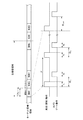
図6は、本実施形態に係るカメラ動作タイミングを説明するための図である。
本実施例においては、図6(a)に示されるように、タイミングコントローラ9は、各ターゲット距離領域(例えば、領域1)ごとに各色光の発光周期を時間的に切り替えるように発光部5を制御する。すなわち、領域1を撮像する際には、タイミングコントローラ9は、まず赤色光源から赤色パルス光を所定の発光周期で発光させ、当該赤色パルス光の発光周期に応じた撮像タイミングで露光(ゲート開閉動作)を行う。すなわち、赤色パルス光の複数回の発光および露光を行い、赤色パルス光による領域1の撮像画像(1フレームあるいは数フレーム)を取得する。その後、一定の読出し期間が設けられ、タイミングコントローラ9は当該読出し期間内に、画像処理部10(距離画像データ生成部10aおよびカラー画像データ生成部10b)に対し、赤色パルス光による領域1の撮像画像の画像処理指令信号を出力する。次いで、タイミングコントローラ9は、緑色光源から緑色パルス光を所定の発光周期で発光させ、当該緑色光の発光周期に応じた撮像タイミングで露光を行う。その後、一定の読出し期間が設けられ、タイミングコントローラ9は当該読出し期間内に、画像処理部10に対し、緑色パルス光による領域1の撮像画像(1フレームあるいは数フレーム)の画像処理指令信号を出力する。次いで、タイミングコントローラ9は、青色光源から青色パルス光を所定の発光周期で発光させ、当該青色光の発光周期に応じた撮像タイミングで露光を行う。その後、一定の読出し期間が設けられ、タイミングコントローラ9は当該読出し期間内に、画像処理部10に対し、青色パルス光による領域1の撮像画像(1フレームあるいは数フレーム)の画像処理指令信号を出力する。FIG. 6 is a diagram for explaining the camera operation timing according to the present embodiment.
In this embodiment, as shown in FIG. 6A, the
このように、各色光の複数回の発光および露光を時間的に切り替えて行うことで、領域1に対して各色光の反射光を撮像した撮像画像がそれぞれ取得される。各RGB光について1枚(1フレーム)ずつ撮像画像が取得されても良く、あるいは各光について複数の撮像画像(数フレーム)が取得されても良い。その後、領域2〜領域nまでの各ターゲット距離領域において各色光の発光周期を時間的に切り替えて撮像を行うことで、各領域に対して各色光に基づく撮像画像がそれぞれ取得される。
In this way, by switching the light emission and exposure of each color light a plurality of times in a timely manner, captured images obtained by capturing the reflected light of each color light with respect to the
物体によって分光反射率が異なるため、RGB光のうち反射光の強度が小さい光によって撮像された撮像画像は、S/N比が悪くなり、測距精度も低下する。そこで本実施形態においては、物体によって分光反射率が異なることを利用し、画像処理部10は、RGBの各色光による撮像画像から得られる距離情報に対して演算処理を行い、RGB光のうち物体からの反射光強度が高い色の光の反射率により各色光に対する対象物の分光反射率を補正する。これにより、距離検出精度をより高めることができる。
Since the spectral reflectance differs depending on the object, the captured image captured by the light having a low intensity of the reflected light among the RGB light has a poor S / N ratio and the distance measurement accuracy is also lowered. Therefore, in the present embodiment, utilizing the fact that the spectral reflectance differs depending on the object, the
また、カラー画像データ生成部10bは、赤色パルス光の出射および露光により得られた赤色画像と、緑色パルス光の出射および露光により得られた緑色画像と、青色パルス光の出射および露光により得られた青色画像とを合成してカラー画像データを生成する。距離画像データ生成部10aにより生成された距離画像データとカラー画像データ生成部10bにより生成されたカラー画像データとはそれぞれ別個に物体認識処理部3へ出力されても良く、これらが画像処理部10にて合成された合成画像データが物体認識処理部3へ出力されても良い。
Further, the color image
なお、ターゲット距離領域について各色光の反射光を撮像した撮像画像を取得した後に、当該撮像画像に含まれる物体までの距離を算出するために、本実施形態においては電荷振り分け方式を用いている。この方式においては、物体からの反射光の露光により得られた電荷を位相の異なる信号電荷として高速度カメラ8に備わる所定の蓄積領域に振り分ける。振り分けられた信号電荷は、対応する各信号電荷蓄積領域にそれぞれ蓄積される。各信号電荷蓄積領域に蓄積された信号電荷は、蓄積された電荷量に対応した出力として読み出され、これらの出力の比率に基づいて、対象物までの距離が算出される。例えば、図6(b)に示すように、タイミングコントローラ9は、パルス光の1回の発光に対する物体からの反射光を、ある周期の露光期間1と、当該露光期間1とは位相周期の異なる露光期間2との両方で露光するように露光制御を行う。露光期間1で蓄積された電荷量と露光期間2で蓄積された電荷量との比率を用いて車両Vから物体までの距離を算出することができる。
In this embodiment, the charge distribution method is used in order to calculate the distance to the object included in the captured image after acquiring the captured image obtained by capturing the reflected light of each color light in the target distance region. In this method, the electric charges obtained by the exposure of the reflected light from the object are distributed as signal charges having different phases to a predetermined storage area provided in the high-
以上説明した本実施例の画像取得装置2によれば、以下に列挙する効果を奏する。 According to the image acquisition device 2 of the present embodiment described above, the effects listed below are obtained.
(1)赤色光を発光する赤色光源、緑色光を発光する緑色光源および青色光を発光する青色光源を備えたRGB光源部5から各色光を発光し、各色光の反射光を例えば単眼カメラである高速度カメラ8により撮像してターゲット距離領域の異なる複数の撮像画像を取得するとともに、画像処理部10(カラー画像データ生成部10b)において各色光によりそれぞれ取得された撮像画像を合成してカラー画像データを生成する。この構成によれば、本実施形態の車両用画像取得装置2は、RGBフィルタのない安価な単眼カメラで、距離情報を有する撮像画像に加えて合成されたカラー画像を得ることができる。そのため、従来のようにミリ波レーダとステレオカメラとを併用するミリ波レーダー・ステレオカメラフュージョンセンサ等で実現されていた運転支援システムの大幅なコスト削減が可能である。また、パルス光を出射する発光部として異なる複数の波長の光を出射可能なRGB光源部を用いることで、距離検出の精度(測距精度)を向上させることができる。
(1) Each color light is emitted from an RGB
なお、上記実施形態に係る画像取得装置2を備えた障害物検出装置1を、いわゆるAHB(オートマチック・ハイビーム)システムやADB(アダプティブ・ドライビング・ビーム)システムの配光制御に用いることが好適である。例えば、画像取得装置2にて得られたターゲット距離領域の異なる複数の撮像画像から距離情報を取得するとともに、合成されたカラー画像から対象物情報を取得して、物体が車両であるか否かを判別することができる。このように、ミリ波レーダとカメラを併用して得ていた距離情報と対象物情報とを画像取得装置2のみで得ることができ、AHBシステムやADBシステムの配光制御をより安価に行うことができる。
It is preferable to use the
(2)タイミングコントローラ9は、各色光の発光周期を時間的に切り替えて、各色光の発光周期に応じて撮像タイミングを制御する。この構成によれば、画像処理アルゴリズムを簡易化することができる。
(2) The
(3)画像処理部10は、各ターゲット距離領域の撮像画像を演算処理することで各色光に対する対象物(物体)の反射率を補正し、距離情報を取得することが好ましい。この構成によれば、対象物の分光反射率を補正することで、より精度の高い距離画像を得ることができる。
(3) It is preferable that the
以上、本開示を実施するための形態を、実施例に基づき説明したが、本開示の具体的な構成については、実施例の構成に限らず、特許請求の範囲の各請求項に係る発明の要旨を逸脱しない限り、設計変更や追加等は許容される。 The embodiment for carrying out the present disclosure has been described above based on the examples, but the specific configuration of the present disclosure is not limited to the configuration of the examples, but the invention according to each claim in the claims. Design changes and additions are permitted as long as they do not deviate from the gist.
例えば、撮像対象長さ、撮像対象距離の変化量、ターゲット距離領域ごとのフレーム数などは、高速度カメラ8や画像処理部10の性能に応じて適宜設定することができる。
For example, the length to be imaged, the amount of change in the distance to be imaged, the number of frames for each target distance region, and the like can be appropriately set according to the performance of the high-
上記実施の形態では、図1に示されるように、高速度カメラ8が画像取得部として機能する構成としているが、この例に限られない。例えば、画像取得部としての機能を画像処理部10が有していても良く、あるいは高速度カメラ8と画像処理部10との間に画像取得部として撮像画像を格納する別個のメモリが設けられても良い。
In the above embodiment, as shown in FIG. 1, the high-
上記実施の形態では、図1に示されるように、対物レンズ6と高速度カメラ8との間に光増倍部7(ゲート7a、イメージインテンシファイア7b)が設けられた構成としているが、この例に限られない。例えば、光増倍部7を設けず、高速度カメラ8内で所定の撮像タイミングでゲーティングを行って複数の撮像画像を取得することも可能である。
In the above embodiment, as shown in FIG. 1, a photomultiplier tube 7 (
上記実施の形態では、画像処理部10により距離画像データを生成することで物体認識を行う構成としているが、高速度カメラ8で撮像された個々のターゲット距離の撮像画像から物体認識を行っても良い。
In the above embodiment, the
本出願は、2015年12月21日出願の日本特許出願・出願番号2015−248825に基づくものであり、その内容はここに参照として取り込まれる。 This application is based on Japanese Patent Application No. 2015-248825 filed on December 21, 2015, the contents of which are incorporated herein by reference.
Claims (5)
赤色光を発光する赤色光源、緑色光を発光する緑色光源および青色光を発光する青色光源を備え、所定方向に所定の発光周期で各色光を出射するRGB光源部と、
ターゲット距離領域に応じて設定される撮像タイミングで前記ターゲット距離領域から帰ってくる反射光を撮像し、ターゲット距離領域の異なる複数の撮像画像を取得する画像取得部と、
前記各色光の発光周期および前記撮像タイミングを制御するタイミング制御部と、
前記複数の撮像画像から距離情報を取得するとともにカラー画像を生成する画像処理部と、を備え、
前記RGB光源部は、前記赤色光源からの前記赤色光の発光タイミングと、前記緑色光源からの前記緑色光の発光タイミングと、前記青色光源からの前記青色光の発光タイミングと、を互いに異ならせるようにして前記各色光を前記車両の外部に出射し、
前記画像処理部は、異なるタイミングで出射された前記各色光の反射光を撮像することによりそれぞれ取得された前記複数の撮像画像を合成して前記カラー画像を生成する、車両用画像取得装置。 An image acquisition device for vehicles mounted on a vehicle.
An RGB light source unit that includes a red light source that emits red light, a green light source that emits green light, and a blue light source that emits blue light, and emits each color light in a predetermined direction at a predetermined emission cycle.
An image acquisition unit that captures the reflected light returning from the target distance region at an imaging timing set according to the target distance region and acquires a plurality of captured images having different target distance regions.
A timing control unit that controls the emission cycle of each color light and the imaging timing,
An image processing unit that acquires distance information from the plurality of captured images and generates a color image is provided.
The RGB light source unit makes the emission timing of the red light from the red light source, the emission timing of the green light from the green light source, and the emission timing of the blue light from the blue light source different from each other. Then, each of the colored lights is emitted to the outside of the vehicle.
Wherein the image processing unit, said different emitted at the timing by combining a plurality of captured images obtained respectively by imaging reflected light of each color light to produce the color image, the image acquisition system for a vehicle.
Applications Claiming Priority (3)
| Application Number | Priority Date | Filing Date | Title |
|---|---|---|---|
| JP2015248825 | 2015-12-21 | ||
| JP2015248825 | 2015-12-21 | ||
| PCT/JP2016/085813 WO2017110416A1 (en) | 2015-12-21 | 2016-12-01 | Image acquisition device to be used by vehicle, and vehicle equipped with image acquisition device to be used by vehicle |
Publications (2)
| Publication Number | Publication Date |
|---|---|
| JPWO2017110416A1 JPWO2017110416A1 (en) | 2018-10-04 |
| JP6942637B2 true JP6942637B2 (en) | 2021-09-29 |
Family
ID=59089394
Family Applications (1)
| Application Number | Title | Priority Date | Filing Date |
|---|---|---|---|
| JP2017557835A Active JP6942637B2 (en) | 2015-12-21 | 2016-12-01 | Vehicles equipped with a vehicle image acquisition device and a vehicle image acquisition device |
Country Status (5)
| Country | Link |
|---|---|
| US (1) | US10953813B2 (en) |
| EP (1) | EP3396947A4 (en) |
| JP (1) | JP6942637B2 (en) |
| CN (1) | CN108370435B (en) |
| WO (1) | WO2017110416A1 (en) |
Families Citing this family (3)
| Publication number | Priority date | Publication date | Assignee | Title |
|---|---|---|---|---|
| EP4035940A4 (en) * | 2019-09-26 | 2022-11-16 | Koito Manufacturing Co., Ltd. | Gating camera, automobile, vehicle lamp, image processing device, and image processing method |
| JP7365487B2 (en) * | 2020-02-27 | 2023-10-19 | 株式会社Fuji | Image correction method, imaging device and inspection device |
| CN111948669B (en) * | 2020-08-11 | 2023-01-10 | 锐驰智光(苏州)科技有限公司 | Hyperspectral data information acquisition system based on laser radar |
Family Cites Families (11)
| Publication number | Priority date | Publication date | Assignee | Title |
|---|---|---|---|---|
| JPH0865690A (en) * | 1994-08-24 | 1996-03-08 | Sony Tektronix Corp | Color still picture photographing device |
| KR100268048B1 (en) | 1996-10-28 | 2000-11-01 | 고바야시 마사키 | Underwater laser imaging apparatus |
| JPH10132932A (en) | 1996-10-28 | 1998-05-22 | Unyusho Daiichi Kowan Kensetsukyoku | Three primary color underwater laser visually confirming device |
| JP4530571B2 (en) * | 2001-04-16 | 2010-08-25 | Hoya株式会社 | 3D image detection device |
| JP5092613B2 (en) * | 2007-08-06 | 2012-12-05 | 日産自動車株式会社 | Distance measuring method and apparatus, and vehicle equipped with distance measuring apparatus |
| JP2009257983A (en) | 2008-04-18 | 2009-11-05 | Calsonic Kansei Corp | Device and method for generating distance image data for vehicle |
| CN101324749B (en) | 2008-07-24 | 2010-07-28 | 上海交通大学 | Method for performing projection display on veins plane |
| JP2011136651A (en) * | 2009-12-28 | 2011-07-14 | Koito Mfg Co Ltd | Vehicular lighting system |
| US8681255B2 (en) * | 2010-09-28 | 2014-03-25 | Microsoft Corporation | Integrated low power depth camera and projection device |
| CN102737389A (en) | 2011-04-13 | 2012-10-17 | 南京大学 | Adaptive reflectivity correction method for color coding structure light scanning system |
| US10912516B2 (en) * | 2015-12-07 | 2021-02-09 | Panasonic Corporation | Living body information measurement device, living body information measurement method, and storage medium storing program |
-
2016
- 2016-12-01 CN CN201680074554.3A patent/CN108370435B/en active Active
- 2016-12-01 US US16/065,031 patent/US10953813B2/en active Active
- 2016-12-01 EP EP16878309.0A patent/EP3396947A4/en not_active Withdrawn
- 2016-12-01 JP JP2017557835A patent/JP6942637B2/en active Active
- 2016-12-01 WO PCT/JP2016/085813 patent/WO2017110416A1/en active Application Filing
Also Published As
| Publication number | Publication date |
|---|---|
| EP3396947A4 (en) | 2019-08-21 |
| EP3396947A1 (en) | 2018-10-31 |
| CN108370435A (en) | 2018-08-03 |
| WO2017110416A1 (en) | 2017-06-29 |
| JPWO2017110416A1 (en) | 2018-10-04 |
| US10953813B2 (en) | 2021-03-23 |
| CN108370435B (en) | 2020-12-29 |
| US20190016274A1 (en) | 2019-01-17 |
Similar Documents
| Publication | Publication Date | Title |
|---|---|---|
| JP6851985B2 (en) | Vehicle and vehicle image acquisition method equipped with vehicle image acquisition device, control device, vehicle image acquisition device or control device | |
| JP6868570B2 (en) | Vehicle and vehicle image acquisition method equipped with vehicle image acquisition device, control device, vehicle image acquisition device or control device | |
| JP6766071B2 (en) | Image acquisition device for vehicles and vehicles equipped with it | |
| JP6766072B2 (en) | Vehicle sensors and vehicles equipped with them | |
| JP6851986B2 (en) | Vehicle and vehicle image acquisition method equipped with vehicle image acquisition device, control device, vehicle image acquisition device or control device | |
| JP7201592B2 (en) | System for characterizing vehicle surroundings | |
| JP6942637B2 (en) | Vehicles equipped with a vehicle image acquisition device and a vehicle image acquisition device | |
| WO2020175117A1 (en) | Distance measurement device, distance measurement method, and program | |
| WO2020175118A1 (en) | Distance measurement device, distance measurement method, and program | |
| WO2021060397A1 (en) | Gating camera, automobile, vehicle lamp, image processing device, and image processing method | |
| WO2021084891A1 (en) | Movement amount estimation device, movement amount estimation method, movement amount estimation program, and movement amount estimation system | |
| WO2022163721A1 (en) | Gated camera, vehicular sensing system, and vehicular lamp |
Legal Events
| Date | Code | Title | Description |
|---|---|---|---|
| A621 | Written request for application examination |
Free format text: JAPANESE INTERMEDIATE CODE: A621 Effective date: 20190924 |
|
| A131 | Notification of reasons for refusal |
Free format text: JAPANESE INTERMEDIATE CODE: A131 Effective date: 20201020 |
|
| A521 | Request for written amendment filed |
Free format text: JAPANESE INTERMEDIATE CODE: A523 Effective date: 20201216 |
|
| A131 | Notification of reasons for refusal |
Free format text: JAPANESE INTERMEDIATE CODE: A131 Effective date: 20210608 |
|
| A521 | Request for written amendment filed |
Free format text: JAPANESE INTERMEDIATE CODE: A523 Effective date: 20210726 |
|
| TRDD | Decision of grant or rejection written | ||
| A01 | Written decision to grant a patent or to grant a registration (utility model) |
Free format text: JAPANESE INTERMEDIATE CODE: A01 Effective date: 20210817 |
|
| A61 | First payment of annual fees (during grant procedure) |
Free format text: JAPANESE INTERMEDIATE CODE: A61 Effective date: 20210908 |
|
| R150 | Certificate of patent or registration of utility model |
Ref document number: 6942637 Country of ref document: JP Free format text: JAPANESE INTERMEDIATE CODE: R150 |