JP6941364B2 - Panel structure and prefabricated shelter with it - Google Patents
Panel structure and prefabricated shelter with it Download PDFInfo
- Publication number
- JP6941364B2 JP6941364B2 JP2017229719A JP2017229719A JP6941364B2 JP 6941364 B2 JP6941364 B2 JP 6941364B2 JP 2017229719 A JP2017229719 A JP 2017229719A JP 2017229719 A JP2017229719 A JP 2017229719A JP 6941364 B2 JP6941364 B2 JP 6941364B2
- Authority
- JP
- Japan
- Prior art keywords
- wood board
- board material
- wood
- panel structure
- iron plate
- Prior art date
- Legal status (The legal status is an assumption and is not a legal conclusion. Google has not performed a legal analysis and makes no representation as to the accuracy of the status listed.)
- Active
Links
Images


Description
本発明は、地震や災害等から人間の身体生命を守るシェルター(内部に避難防護室が形成された耐震構造物)の側壁、底壁、天井壁などとして使用されるパネル構造体、及び当該パネル構造体を備えた組立式シェルターに関するものである。 The present invention relates to a panel structure used as a side wall, bottom wall, ceiling wall, etc. of a shelter (seismic structure having an evacuation protection chamber formed inside) that protects human body life from earthquakes, disasters, and the like, and the panel. It relates to a prefabricated shelter with a structure.
大地震の発生時に建築物の倒壊から身を守るには、一手段として、建物内の一部屋の内部にシェルターを設置し、そこを地震が発生した場合の避難場所とする方策が考えられる。このようなシェルターを屋内に設置することは、屋内にいる人間の身体生命を地震等の災害から保護することにつながり、安全の観点から重要なことである。特に、時代を経た家屋(耐震基準未達)は、耐震基準を満たしている家屋に比較して地震等の災害による倒壊、損傷の可能性が高く、そこにいる人間の安全が確保され難いことから、屋内にシェルターを設置することの重要性は非常に高い。 One way to protect yourself from the collapse of a building in the event of a major earthquake is to install a shelter inside a room in the building and use it as an evacuation site in the event of an earthquake. Installing such a shelter indoors leads to protection of the physical life of human beings indoors from disasters such as earthquakes, and is important from the viewpoint of safety. In particular, aged houses (those that do not meet the earthquake resistance standards) are more likely to collapse or be damaged due to a disaster such as an earthquake than houses that meet the earthquake resistance standards, and it is difficult to ensure the safety of the people there. Therefore, it is very important to install a shelter indoors.
しかし、屋内にシェルターを設置するにあたり、軸組工法で行うのでは、建築工程において高度な施工技術が要求され、家屋の大改修を要することもあり、容易に実施出来るものではない。 However, when installing a shelter indoors, if the shelter is installed by the frame construction method, advanced construction technology is required in the construction process, and a major renovation of the house may be required, so it is not easy to carry out.
一方、近年、パネル構造体である直交集成板CLT(平成25年農林省告示第3079号直交集成板の日本農林規格)が海外で普及している。特許文献1には、直方体状の複数のラミナを並べて成るプライを、ラミナの並び方向が互いに直交するように複数層に重ね合わせ、かつ、重ね合わせ面を互いに接着して成る直交集成板CLTが記載されている。直交集成板CLTは強度が高く、複数の直交集成板CLTを組み立ててシェルターとすることもできる。よって、直交集成板CLTを利用すれば軸組工法によらずに屋内にシェルターを設置することができる。
On the other hand, in recent years, the cross laminated board CLT (2013 Ministry of Agriculture and Forestry Notification No. 3079 Japanese Agricultural Standard for Orthogonal Laminated Wood), which is a panel structure, has become widespread overseas.
しかし、直交集成板CLTは単位面積当たりの重量が大きいため、直交集成板CLTを運搬して組み立てるには専用の車両やクレーンを使わねばならず、直交集成板CLTを組み立てて屋内にシェルターを設置することは容易ではない。一方、シェルターは地震の震動や家屋の倒壊及び損傷による外力に耐え得るものでなければならないため、シェルターを構成する直交集成板CLTを安易に軽量化することもできない。このため、重量化を回避しながら曲げなどに対する強度を高めることができるパネル構造体の開発が要請されていた。 However, since the cross laminated timber CLT has a large weight per unit area, a dedicated vehicle or crane must be used to transport and assemble the cross laminated timber CLT, and the orthogonal laminated timber CLT is assembled and a shelter is installed indoors. It is not easy to do. On the other hand, since the shelter must be able to withstand the external force caused by the shaking of the earthquake and the collapse and damage of the house, it is not possible to easily reduce the weight of the cross laminated board CLT constituting the shelter. Therefore, there has been a demand for the development of a panel structure capable of increasing the strength against bending while avoiding weight increase.
本発明は上述の点に鑑みてなされたものであり、その目的は、重量化を回避しながら強度を効果的に高めることが可能なパネル構造体及びこれを備える組立式シェルターを提供することにある。 The present invention has been made in view of the above points, and an object of the present invention is to provide a panel structure capable of effectively increasing strength while avoiding weight increase, and an assembling shelter provided with the panel structure. be.
上記課題を解決するため、本発明にかかるパネル構造体(10)は、金属製の板材であって、その面内の一方向へ直線状に延びて表面(11f)又は裏面(11g)に向かって突出する複数の突条(11a,11b)を有し、該一方向と直交する方向の断面が表裏へ交互に突出する形状である波形鉄板(11)と、前記波形鉄板(11)の前記表面(11f)と前記裏面(11g)との少なくともいずれかに固定された平板状の第1木板材(12,13)と、を備えることを特徴とする。 In order to solve the above problems, the panel structure (10) according to the present invention is a metal plate material, which extends linearly in one direction in the plane toward the front surface (11f) or the back surface (11g). A corrugated iron plate (11) having a plurality of protruding ridges (11a, 11b) and having a shape in which cross sections in a direction orthogonal to the one direction alternately project to the front and back, and the corrugated iron plate (11). It is characterized by comprising a flat plate-shaped first wooden board material (12, 13) fixed to at least one of a front surface (11f) and the back surface (11g).
本発明にかかるパネル構造体によれば、波形鉄板とその表面又は裏面に固定された平板状の第1木板材とを備えることで、外力に対して非常に高い強度(面の曲げ強度等)を有するパネル構造体を実現することができる。すなわち、その面内の一方向へ直線状に延びる複数の突条を有し、該一方向と直交する方向の断面が表裏へ交互に突出する形状である波形鉄板は、それ自体のみ(単体)でも高い強度を有しているところ、該波形鉄板の表面又は裏面に木板材を固定したことで、波形鉄板の強度を更に上回る高い強度を確保することができる。これにより、当該パネル構造体を用いて組み立てた組立式シェルターを強固で頑丈なものとすることができるので、当該組立式シェルターを災害時の避難用シェルターとして用いるために必要な強度・耐性を確保することが可能となる。 According to the panel structure according to the present invention, by providing the corrugated iron plate and the flat plate-shaped first wooden plate material fixed to the front surface or the back surface thereof, the strength is extremely high against an external force (bending strength of the surface, etc.). It is possible to realize a panel structure having. That is, the corrugated iron plate having a plurality of ridges extending linearly in one direction in the plane and having a shape in which the cross sections in the direction orthogonal to the one direction alternately project to the front and back is only itself (single unit). However, when it has high strength, by fixing the wood board material to the front surface or the back surface of the corrugated iron plate, it is possible to secure a high strength further exceeding the strength of the corrugated iron plate. As a result, the prefabricated shelter assembled using the panel structure can be made strong and sturdy, so that the strength and resistance required for using the prefabricated shelter as an evacuation shelter in the event of a disaster are secured. It becomes possible to do.
また、本発明のパネル構造体は、前記第1木板材(12,13)は、前記波形鉄板(11)の前記表面(11f)に固定された第1表側木板材(12)と、前記波形鉄板(11)の前記裏面(11g)に固定された第1裏側木板材(13)とを含んでもよい。 Further, in the panel structure of the present invention, the first wooden board material (12, 13) has the first front side wooden board material (12) fixed to the surface (11f) of the corrugated iron plate (11) and the corrugated iron plate (11). The first back side wood board material (13) fixed to the back surface (11 g) of the iron plate (11) may be included.
この構成によれば、第1木板材は、波形鉄板の表面に固定された第1表側木板材と、波形鉄板の裏面に固定された第1裏側木板材とを含むことで、表面と裏面の両方に固定した木板材で波形鉄板を挟み込んだ状態(サンドイッチ状態)で固定することができる。これにより、パネル構造体の強度(曲げ強度等)をより高くすることが可能となる。また、波形鉄板の表面と裏面の両方に木板材が固定されていることで、パネル構造体の表面と裏面の両方に波形鉄板が露出しないように構成されるので、パネル構造体の外観デザインを向上させることができる。 According to this configuration, the first wooden board material includes the first front side wooden board material fixed to the front surface of the corrugated iron plate and the first back side wooden board material fixed to the back surface of the corrugated iron plate, thereby forming the front surface and the back surface. It can be fixed in a state where the corrugated iron plate is sandwiched between the wooden boards fixed to both (sandwich state). This makes it possible to increase the strength (bending strength, etc.) of the panel structure. In addition, since the wooden board material is fixed to both the front surface and the back surface of the corrugated iron plate, the corrugated iron plate is not exposed on both the front surface and the back surface of the panel structure. Can be improved.
また、本発明のパネル構造体は、前記第1木板材(12,13)は、その面内の一方向に沿って延びる木目又は木材の繋目(12b,13b)を有し、前記波形鉄板(11)の前記突条(11a,11b)の延びる方向と前記第1木板材(12,13)の前記木目又は木材の繋目(12b,13b)の延びる方向とが互いに交差する方向であってよい。 Further, in the panel structure of the present invention, the first wood board material (12, 13) has a wood grain or a wood joint (12b, 13b) extending along one direction in the plane thereof, and the corrugated iron plate. The extending direction of the ridges (11a, 11b) of (11) and the extending direction of the grain of wood or the joint of wood (12b, 13b) of the first wood board material (12, 13) intersect each other. You can.
この構成によれば、波形鉄板の突条の延びる方向と第1木板材の木目又は木材の繋目の延びる方向とが互いに交差する方向であることで、波形鉄板に第1木板材が固定されてなるパネル構造体における曲げ強度を面内の複数方向に対して向上させることができる。したがって、パネル構造体の外力に対する強度(耐性)をより高くすることが可能となる。 According to this configuration, the first wood board material is fixed to the corrugated iron plate by the direction in which the extending direction of the ridge of the corrugated iron plate and the extending direction of the grain of the first wood board material or the extending direction of the wood joint intersect each other. The bending strength of the panel structure can be improved in a plurality of in-plane directions. Therefore, it is possible to increase the strength (resistance) of the panel structure against an external force.
また、本発明のパネル構造体は、前記第1木板材(12,13)の前記波形鉄板(11)が固定された面と反対側の面(12f,13g)に固定された平板状の第2木板材(14,15)を更に備えてもよい。 Further, the panel structure of the present invention is a flat plate-shaped first wood board material (12, 13) fixed to a surface (12f, 13g) opposite to the surface on which the corrugated iron plate (11) is fixed. 2 Wood board materials (14, 15) may be further provided.
この構成によれば、第1木板材の波形鉄板が固定された面と反対側の面に固定された平板状の第2木板材を更に備えることで、波形鉄板と第1木板材のみを備える場合と比較して、外力に対してさらに高い強度(面の曲げ強度等)を有するパネル構造体を実現することができる。これにより、当該パネル構造体を用いて組み立てた組立式シェルターをさらに強固で頑丈なものとすることができるので、当該組立式シェルターを災害時の避難用シェルターとして用いるために必要な強度・耐性を確保することが可能となる。 According to this configuration, only the corrugated iron plate and the first wood plate material are provided by further providing the flat plate-shaped second wood plate material fixed to the surface opposite to the surface on which the corrugated iron plate of the first wood plate material is fixed. It is possible to realize a panel structure having a higher strength (surface bending strength, etc.) with respect to an external force as compared with the case. As a result, the prefabricated shelter assembled using the panel structure can be made stronger and stronger, so that the strength and resistance required for using the prefabricated shelter as an evacuation shelter in the event of a disaster can be obtained. It becomes possible to secure.
また、本発明のパネル構造体は、前記第2木板材(14,15)は、前記第1表側木板材(12)の前記波形鉄板(11)が固定された面と反対側の面(12f)に固定された第2表側木板材(14)と、前記第1裏側木板材(13)の前記波形鉄板(11)が固定された面と反対側の面(13g)に固定された第2裏側木板材(15)とを含んでもよい。 Further, in the panel structure of the present invention, the second wooden board material (14, 15) is the surface (12f) opposite to the surface to which the corrugated iron plate (11) of the first front side wooden board material (12) is fixed. The second front side wood board (14) fixed to) and the second back side wood board (13) fixed to the surface (13 g) opposite to the fixed surface of the corrugated iron plate (11). The back side wood board material (15) may be included.
この構成によれば、第2木板材は、第1表側木板材に固定された第2表側木板材と、第1裏側木板材に固定された第2裏側木板材とを含むことで、波形鉄板の表面側と裏面側の両方に固定した第1、第2表側木板材をさらに第1、第2裏側木板材で挟み込んだ状態(サンドイッチ状態)で固定することができる。したがって、波形鉄板の表面側と裏面側それぞれを二枚ずつの木板材で挟み込んだ状態で固定できるので、パネル構造体の強度(曲げ強度等)をさらに高くすることが可能となる。 According to this configuration, the second wooden board material includes a second front side wooden board material fixed to the first front side wooden board material and a second back side wooden board material fixed to the first back side wooden board material, thereby forming a corrugated iron plate. The first and second front side wooden boards fixed to both the front surface side and the back surface side of the above can be fixed in a state of being further sandwiched between the first and second back side wooden boards (sandwich state). Therefore, since the front surface side and the back surface side of the corrugated iron plate can be fixed in a state of being sandwiched between two wood plate materials, the strength (bending strength, etc.) of the panel structure can be further increased.
また、本発明のパネル構造体は、前記第2木板材(14,15)は、その面内の他の一方向に沿って延びる木目又は木材の繋目(14b,15b)を有し、前記第1木板材(12,13)の前記木目又は木材の繋目(12b,13b)の延びる方向と前記第2木板材(14,15)の前記木目又は木材の繋目(14b,15b)の延びる方向とが互いに交差する方向であってもよい。 Further, in the panel structure of the present invention, the second wood board material (14, 15) has a wood grain or a wood joint (14b, 15b) extending along another direction in the plane thereof. The extending direction of the wood grain or wood joint (12b, 13b) of the first wood board material (12, 13) and the wood grain or wood joint (14b, 15b) of the second wood board material (14, 15). It may be a direction in which the extending directions intersect with each other.
この構成によれば、第1木板材の木目又は木材の繋目の延びる方向と第2木板材の木目又は木材の繋目の延びる方向とが互いに交差する方向であることで、波形鉄板に第1木板材と第2木板材とが固定されてなるパネル構造体における面の曲げ強度を面内のより多数の方向に対して向上させることができる。したがって、パネル構造体の外力に対する強度(耐性)をさらに高くすることが可能となる。 According to this configuration, the extending direction of the wood grain or wood joint of the first wood board and the extending direction of the wood grain or wood joint of the second wood board intersect each other, so that the corrugated iron plate is second. It is possible to improve the bending strength of the surface in the panel structure in which the 1st wood board material and the 2nd wood board material are fixed in more directions in the plane. Therefore, it is possible to further increase the strength (resistance) of the panel structure against an external force.
また、本発明のパネル構造体は、前記波形鉄板(11)と前記第1木板材(12,13)との固定、又は前記第1木板材(12,13)と前記第2木板材(14,15)との固定は、締結具(17a,17b)の締結のみによる固定、あるいは前記締結具(17a,17b)の締結と接着材の塗布との両方による固定であってもよい。 Further, the panel structure of the present invention is fixed to the corrugated iron plate (11) and the first wood board material (12, 13), or the first wood board material (12, 13) and the second wood board material (14). , 15) may be fixed only by fastening the fasteners (17a, 17b), or by both fastening the fasteners (17a, 17b) and applying an adhesive.
この構成によれば、波形鉄板と第1木板材との固定、又は第1木板材と第2木板材との固定を締結具の締結のみによる固定とすれば、パネル構造体を簡単な構成で高い強度を有するものとすることができるので、パネル構造体の製造工程の簡素化、及び低廉化などを図ることができる。また、波形鉄板と第1木板材との固定、又は第1木板材と第2木板材との固定を締結具の締結と接着材の塗布との両方による固定とすれば、波形鉄板と第1木板材、あるいは第1木板材と第2木板材とが剥がれたりすることを効果的に防止できるので、パネル構造体の強度をより確実に確保でき、信頼性を向上させることができる。 According to this configuration, if the corrugated iron plate and the first wood board material are fixed, or the first wood board material and the second wood board material are fixed only by fastening the fasteners, the panel structure can be easily configured. Since it can have high strength, it is possible to simplify the manufacturing process of the panel structure and reduce the cost. The fixing of the corrugated iron and the first wood plate, or if the first and wood plate fixed to the second tree plate engagement of the fastener and fixing by both the application of the adhesive material, corrugated iron and first Since the wood board material or the first wood board material and the second wood board material can be effectively prevented from peeling off, the strength of the panel structure can be more reliably secured and the reliability can be improved.
また、本発明の組立式シェルター(1)は、上記いずれかの構成のパネル構造体(10)を複数備え、前記複数のパネル構造体(10)を組み合わせて中空の箱型に形成してなることを特徴とする。 Further, the assembly type shelter (1) of the present invention includes a plurality of panel structures (10) having any of the above configurations, and the plurality of panel structures (10) are combined to form a hollow box shape. It is characterized by that.
本発明にかかる組立式シェルターによれば、波形鉄板に木板材を固定してなる本発明のパネル構造体を組み合わせて中空の箱型に形成してなることで、当該組立式シェルターを非常に高い強度で頑丈な構造とすることができる。特に、中空の箱形構造のシェルターにおける各壁部に用いたパネル構造体の曲げ強度が高いことで、当該シェルターが倒壊した建物の内部などに設置されていた場合でも、重量物の落下や衝突に対して各壁部が大きく変形することなく耐えることが可能となり、内部に避難した者の安全をより確実に確保することが可能なシェルターとなる。 According to the prefabricated shelter according to the present invention, the prefabricated shelter is very high by combining the panel structures of the present invention formed by fixing a wooden board material to a corrugated iron plate to form a hollow box shape. It can be a strong and sturdy structure. In particular, due to the high bending strength of the panel structure used for each wall in the hollow box-shaped shelter, even if the shelter is installed inside a collapsed building, heavy objects may fall or collide. However, each wall can withstand without being significantly deformed, and it becomes a shelter that can more reliably ensure the safety of those who have evacuated inside.
また、本発明の前記組立式シェルター(1)は、直方体形状の中空の箱型であり、前記複数のパネル構造体(10)は、前記組立式シェルター(1)の底壁(1A)、天井壁(1C)、前後左右の側壁(1E,1G,1I,1K)それぞれを構成するパネル構造体を含み、前記複数のパネル構造体(10)は、それらにおける前記組立式シェルターの内側を向く面(10g)に取り付けた連結固定用の固定具(30、40)のみで互いが連結固定されていてもよい。 The assembled shelter (1) of the present invention is a rectangular parallelepiped hollow box type, and the plurality of panel structures (10) are the bottom wall (1A) and the ceiling of the assembled shelter (1). The panel structures including the wall (1C) and the front, rear, left and right side walls (1E, 1G, 1I, 1K) are included, and the plurality of panel structures (10) are surfaces facing the inside of the prefabricated shelter in them. They may be connected and fixed to each other only by the connecting and fixing fixtures (30, 40) attached to (10 g).
この構成によれば、組立式シェルターの底壁、天井壁、前後左右の側壁それぞれを構成するパネル構造体が、それらにおける組立式シェルターの内側を向く面に固定した固定具のみで互いが連結固定されていることで、当該組立式シェルターを既存の家屋の一部屋の内部などに簡単に組み立てて設置することが可能となる。すなわち、部屋の床、天井、壁それぞれの内面に沿うように底壁、天井壁、前後左右の側壁それぞれを構成するパネル構造体を配置して組み合わせ、その状態でパネル構造体で形成された箱型の内部から固定具を取り付けることで、組立式シェルターを組み立ててそのまま設置することができる。したがって、簡単な工程で容易に組立及び設置が可能な組立式シェルターとなる。
なお、上記の括弧内の符号は、後述する実施形態の対応する構成要素の符号を本発明の一例として示したものである。
According to this configuration, the panel structures constituting the bottom wall, the ceiling wall, and the front, rear, left, and right side walls of the prefabricated shelter are connected and fixed to each other only by the fixture fixed to the inward facing surface of the prefabricated shelter. This makes it possible to easily assemble and install the prefabricated shelter inside a room of an existing house. That is, a box formed by arranging and combining panel structures constituting the bottom wall, the ceiling wall, and the front, rear, left, and right side walls along the inner surfaces of the floor, ceiling, and wall of the room, and forming the panel structure in that state. By attaching the fixture from the inside of the mold, the prefabricated shelter can be assembled and installed as it is. Therefore, it becomes an assembly type shelter that can be easily assembled and installed in a simple process.
The reference numerals in parentheses above indicate the reference numerals of the corresponding components of the embodiments described later as an example of the present invention.
本発明にかかるパネル構造体によれば、簡単な構造で重量化を回避しながら強度(特に面の曲げ強度)を効果的に高めることができる。また、本発明にかかる組立式シェルターによれば、組立が容易な簡単な構造でありながら、非常に高い強度で頑丈なものとすることができる。 According to the panel structure according to the present invention, the strength (particularly the bending strength of the surface) can be effectively increased while avoiding weighting with a simple structure. Further, according to the assembling type shelter according to the present invention, it is possible to make the structure very strong and sturdy while having a simple structure that is easy to assemble.
以下、添付図面を参照して本発明の実施形態を詳細に説明する。
〔第1実施形態〕
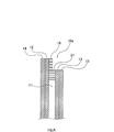
図1は、本発明の第1実施形態にかかるパネル構造体10の構成部品を示す分解斜視図である。同図に示すように、パネル構造体10は、波形鉄板11と、波形鉄板11の表面11f側(図1の上面側)と裏面11g側(図1の下面側)とにそれぞれ固定(貼付固定)された平板状の木板材(第1木板材)からなる第1表側木板材12及び第1裏側木板材13と、第1表側木板材12の波形鉄板11が固定された面と反対側の面12f(図1の上面)と第1裏側木板材13の波形鉄板11が固定された面と反対側の面13g(図1の下面)とにそれぞれ固定(貼付固定)された平板状の木板材(第2木板材)からなる第2表側木板材14及び第2裏側木板材15とを備えて構成されている。
Hereinafter, embodiments of the present invention will be described in detail with reference to the accompanying drawings.
[First Embodiment]
FIG. 1 is an exploded perspective view showing components of the
波形鉄板11は、外形が略長方形状の金属製の板材であって、その面内の一方向(図では長方形状の長手方向)へ直線状に延びて表面11f又は裏面11gに向かって突出するる複数の突条11a,11bを有し、該一方向と直交する方向(図では長手方向に直交する方向)の断面が表裏へ交互に突出する波型形状になっている。
The
第1表側木板材12、第1裏側木板材13、第2表側木板材14、第2裏側木板材15は、いずれも外形が波形鉄板11と同型の略長方形状の木製の板材である。これら第1表側木板材12、第1裏側木板材13、第2表側木板材14、第2裏側木板材15は、一枚板で構成された板材であってもよいし、複数の板材を面方向に繋ぎ合わせた構成の合板や複数の薄い板を貼り合わせてなる合板などであってもよい。
The first front side
そして、第1表側木板材12と第1裏側木板材13は、それらの面内の一方向(長手方向に直交する方向)に沿って略直線状に延びる木目又は木材の繋目(以下、木目等という。)12b,13bを有している。そして、波形鉄板11の突条11a,11bの延びる方向と第1表側木板材12と第1裏側木板材13の木目12b,13bの延びる方向とが互いに直交する方向となっている。また、第2表側木板材14と第2裏側木板材15は、それらの面内の一方向(長手方向)に沿って延びる木目等14b,15bを有している。そして、第1表側木板材12と第1裏側木板材13の木目等12b,13bの延びる方向と第2表側木板材14と第2裏側木板材15の木目等14b,15bの延びる方向とが互いに直交する方向となっている。なお、第1表側木板材12と第1裏側木板材13、及び第2表側木板材14と第2裏側木板材15は同一構成の部材であり、波形鉄板11に対するパネル構造体10の表面側の構造と裏面側の構造は互いに同じである。
The first front side
また、波形鉄板11、第1表側木板材12、第2表側木板材14それぞれの互いに対応する位置には貫通穴(ボルト挿通穴)11d,12d,14dが形成されている。貫通穴11dは、波形鉄板11の突条11aに沿ってその延伸方向(波形鉄板11の長手方向)で等間隔に複数個が形成されている。そして、各貫通穴11d,12d,14dにボルト(締結具)17aが挿通されてナット(締結具)17bで固定されている。これにより、波形鉄板11の表面11f側に第1表側木板材12と第2表側木板材14がこの順に固定(貼付固定)されている。また、波形鉄板11、第1裏側木板材13、第2裏側木板材15それぞれの互いに対応する位置にも貫通穴(ボルト挿通穴)11d,13d,15dが形成されている。貫通穴11d,13d,15dは、波形鉄板11の突条11bに沿ってその延伸方向(波形鉄板11の長手方向)で等間隔に複数個が形成されている。そして、各貫通穴11d,13d,15dにボルト(締結具)17aが挿通されてナット(締結具)17bで固定されている。これにより、波形鉄板11の裏面11g側に第1裏側木板材13と第2裏側木板材15がこの順に固定(貼付固定)されている。なお、図1では、パネル構造体10に設けた貫通穴11d,12d,14dあるいは貫通穴11d,13d,15d及びボルト17aとナット17bのうちの一部のみを図示しているが、実際には、これら貫通穴やボルト及びナットは、パネル構造体10の面内の全体に等間隔で多数が配列されている。
Further, through holes (bolt insertion holes) 11d, 12d, 14d are formed at positions corresponding to each other of the
また、図示は省略するが、波形鉄板11と第1表側木板材12とが接する面、及び第1表側木板材12と第2表側木板材14とが接する面には接着剤が塗布されている。同様に、波形鉄板11と第1裏側木板材13とが接する面、及び第1裏側木板材13と第2裏側木板材15とが接する面にも接着剤が塗布されている。したがって、第1表側木板材12、第1裏側木板材13、第2表側木板材14、第2裏側木板材15との貼付固定は、上記のボルト17a及びナット17bの締結による固定と、接着剤による接着固定との両方で行われている。なお、ボルト17a及びナット17bのみで必要な固定強度を確保できる場合には、接着剤の塗布を省略することも可能である。
Although not shown, an adhesive is applied to the surface where the
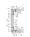
図2は、パネル構造体10の詳細構成を示す図で、(a)は正面図、(b)は右側面図、(c)は(a)のX−X断面図である。また、図3は、パネル構造体10の端辺18の断面(図2(b)のY部分)を拡大した部分拡大図である。なお、以下の説明では、パネル構造体10の第2表側木板材14側の面(図1の上側の面)を外面10fといい、第2裏側木板材15側の面(図1の下側の面)を内面10gという。
2A and 2B are views showing a detailed configuration of the
図2及び図3に示すように、パネル構造体10の波形鉄板11の外形寸法は、波形鉄板11の表面11f側と裏面11g側とに貼り合わせて固定した第1表側木板材12、第1裏側木板材13、第2表側木板材14、第2裏側木板材15よりも若干小さな寸法になっており、波形鉄板11の端辺の外側には、その外形寸法の差を埋めるための埋め木16が取り付けられている。この埋め木16は、パネル構造体10の端辺18に沿う細板状の部材で、波形鉄板11の端辺の外側において第1表側木板材12の端辺と第1裏側木板材13の端辺との間に挟まれた位置に取り付けられている。詳細な図示は省略するが、埋め木16は、パネル構造体10の周囲の四つの端辺18a〜18dそれぞれに取り付けられている。埋め木16は、接着剤で接着固定されている。これにより、パネル構造体の10は、その外面10f及び内面10gが第2表側木板材14及び第2裏側木板材15で覆われており、かつ、周囲の端辺(外縁)18(18a〜18d)の全体が埋め木16で覆われており、これにより、波形鉄板11が外部に露出していない状態となっている。
As shown in FIGS. 2 and 3, the external dimensions of the
また、パネル構造体10の端辺18の断面には、該端辺18に沿って断面の一角が略正方形状(略L字型)に切り欠かれた切欠部21が設けられている。図2に示すパネル構造体10では、切欠部21はパネル構造体10の上端辺18aと下端辺18bとに設けられている。図4は、パネル構造体10の互いに対向する一対の端辺(上端辺18aと下端辺18b、又は左端辺18cと右端辺18d)における切欠部21の配置の種類について説明するための図である。切欠部21を設けたパネル構造体10は、同図(a)に示すように、パネル構造体10の上端辺18a(又は左端辺18c)と下端辺18b(又は右端辺18d)の両方における内面10g側の角部を切り欠いてなる切欠部21を設けたものと、同図(b)に示すように、パネル構造体10の上端辺18a(又は左端辺18c)と下端辺18b(又は右端辺18d)それぞれ内面10g側と外面10f側の角部それぞれを切り欠いてなる切欠部21を設けたものと、同図(c)に示すように、パネル構造体10の上端辺18a(又は左端辺18c)又は下端辺18b(又は右端辺18d)のいずれか一方のみの内面10g側の角部を切り欠いてなる切欠部21を設けたもの、の3種類(3パターン)を用意すればよい。これら3種類の切欠部21を有するパネル構造体10を適宜に組み合わせることで、後述する図5及び図6に示すような構造の組立式シェルター1を形成することが可能である。
Further, the cross section of the
次に、上記構成のパネル構造体10を用いた組立式シェルターについて説明する。図5は、本発明の一実施形態にかかる組立式シェルター1の概略斜視図、図6は、図5に示す組立式シェルター1の平面視の断面図(図5のZ−Z矢視に相当する断面図)である。図5及び図6に示す組立式シェルター1は、上記構成のパネル構造体10を複数枚備えており、それら複数枚のパネル構造体10を組み合わせて中空の箱型に形成されている。パネル構造体10には、組立式シェルター1の底壁1Aを構成するパネル構造体10A,10Bと、天井壁1Cを構成するパネル構造体10C,10Dと、手前側(出入口2を設けた側)の側壁1Eを構成するパネル構造体10E,10Fと、奥側の側壁1Gを構成するパネル構造体10G,10Hと、手前側から見て向かって左側の側壁1Iを構成するパネル構造体10I,10Jと、向かって右側の側壁1Kを構成するパネル構造体10K,10Lとが含まれる。
Next, an assembly-type shelter using the
図7は、組立式シェルター1のパネル構造体10同士の連結部分を示す部分拡大図である。同図に示すように、パネル構造体10には、その端辺18の近傍の内面10gにねじ穴10bが形成されている。このねじ穴10bは、パネル構造体10の内面10g側の木板材13,15を貫通しさらに波形鉄板11を貫通する穴として形成されている。なお、図示は省略するが、ねじ穴10bは、端辺18に沿って複数個が等間隔で形成されている。また、ねじ穴10bは、図示する以外の他のパネル構造体10にも同様に形成されている。上記のねじ穴10bは、パネル構造体10の製造工程で予め形成されているものである。
FIG. 7 is a partially enlarged view showing a connecting portion between the
そして、図7に示すように、連結部分(図では、パネル構造体10Jとパネル構造体10Gとの連結部分,及びパネル構造体10Iとパネル構造体10Eとの連結部分のみを示している。)では、パネル構造体10Jの端辺18とパネル構造体10Gの端辺18とを突き合わせて、一方の切欠部21と他方の切欠部21とが段違いで接合されるように組み合わせる。その状態で、パネル構造体10Jの端辺18とパネル構造体10Gの端辺18との突き合わせ部(角部)の内面側に、断面が略L字型の固定金具(L型金具)30をねじ31の締結で取り付ける。ねじ31は、固定金具30の貫通穴30bを貫通させかつねじ穴10bに螺合させて固定する。ねじ31は、金属性のねじのほか、セラミックねじであってもよい。この際、ねじ穴10bに挿通させたねじ31は、パネル構造体10の波形鉄板11に螺合して固定される。これにより、パネル構造体10Jの端辺18とパネル構造体10Gの端辺18とが突き合わせられた状態でこれらが直角に接合されてその状態で強固に固定される。パネル構造体10Iの端辺18とパネル構造体10Eの端辺18との突き合わせ部も同様の構造で固定する。また、図示は省略するが、接合するパネル構造体10の端辺18及び切欠部21同士の当接面は、接着剤を塗布して接着することが望ましい。
Then, as shown in FIG. 7, the connecting portion (in the figure, only the connecting portion between the
図示および詳細な説明は省略するが、互いの面が角部で直角に突き合わされて接合されている他のパネル構造体10同士の接合部(組立式シェルター1の底壁1Aを構成するパネル構造体10と側壁1E,1I,1K,1Gを構成するパネル構造体10との接合部、側壁1E,1I,1K,1Gを構成するパネル構造体10と天井壁1Cを構成するパネル構造体10との接合部を含む。)も上記と同様の構造である。
Although illustration and detailed description are omitted, a joint portion between other panel structures 10 (a panel structure constituting the
また、図6に示すように、同一面内に並べて配置されているパネル構造体10Iの端辺18とそれに対向するパネル構造体10Jの端辺18とを突き合わせて、一方の切欠部21と他方の切欠部21とが段違いで接合されるように組み合わせる。これには、パネル構造体10I,10Jとして、予め互いが段違いとなるような切欠部21を備えたパネル構造体10(ここでは、図4(a)に示すパネル構造体10と図4(b)に示すパネル構造体10)を選択しておく。その状態で、パネル構造体10Iの端辺18とパネル構造体10Jの端辺18との突き合わせ部の内面側に、断面が平面状の固定金具40をねじ41の締結で取り付ける。詳細な図示は省略するが、この場合も、ねじ41は固定金具40の貫通穴を貫通させかつパネル構造体10のねじ穴に螺合させて固定する。これにより、パネル構造体10Iの端辺18とパネル構造体10Jの端辺18とが突き合わせられた状態でこれらが同一面内で連続するように接合されてその状態で強固に固定される。パネル構造体10Gの端辺18とパネル構造体10Hの端辺18との突き合わせ部や、パネル構造体10Lの端辺18とパネル構造体10Kの端辺18との突き合わせ部も同様の構造で固定する。
Further, as shown in FIG. 6, the
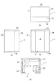
図8は、組立式シェルター1を構成するパネル構造体10A〜10Lそれぞれの外形寸法の一例を示す図である。組立式シェルター1を構成するパネル構造体10A〜10Lの外形寸法は、長手方向が2100mm、1640mmのいずれか、幅方向が820mm、410mm、270mmのいずれか、厚さ方向が85mmである。具体的には、図8(a)〜(f)に示される6種類の外形のパネル構造体10が使用される。なお、ここで示す具体的な寸法はあくまでも一例である。
FIG. 8 is a diagram showing an example of external dimensions of each of the
図9は、4人避難用の組立式シェルター1を示す図であり、(a)は正面図、(b)は上面図、(c)は左側面図、(d)は内部平面図である。同図に示す4人避難用の組立式シェルター1では、奥側の側壁1Gと左右の側壁1I,1Kを構成するパネル構造体10が図8(a)に示す寸法であり、手前側の側壁1Eを構成するパネル構造体10が図8(b)に示す寸法であり、底壁1A、天井壁1Cを構成するパネル構造体10が図8(d)に示す寸法である。したがって、パネル構造体10の寸法としては、図8(a)のパネル構造体10が6枚、図8(b)のパネル構造体10が2枚、図8(d)のパネル構造体10が4枚用いられている。
9A and 9B are views showing an assembly-
また、4人避難用の組立式シェルター1の内部には、一例として、図9(d)に示されるように物を配置することができる。図9(d)に示すように、4人避難用の組立シェルターの内部には、第1避難具E1と、第2避難具E2と、4人分の椅子C1〜C4とが配置される。第1避難具E1としては、飲料水、食糧、携帯トイレ、医薬品、バール、ハンマー、カッター、呼び笛などを備蓄することができる。また、第2避難具E2としては、蓄電池、ラジオTV、ライト、携帯電話の充電器などを備蓄することができる。また、第2避難具E2が配置された付近の領域は、非常時には自動で点灯される。さらに、椅子C1〜C4は、シートベルトが設けられたリクライニングシートである。また、図示は省略するが、組立式シェルター1の内面(居室3内の内面)には、クッション性を有するクッション材(内張り)を貼り付けてもよい。
Further, as an example, an object can be arranged inside the
図10は、2人避難用の組立式シェルター1を示す図であり、(a)は正面図、(b)は上面図、(c)は左側面図、(d)は内部平面図である。同図に示す2人避難用の組立式シェルター1は、奥側の側壁1Gと左右の側壁1I,1Kを構成するパネル構造体10が図8(a)に示す寸法と図8(b)に示す寸法との2種類であり、手前側の側壁1Eを構成するパネル構造体10が図8(b)に示す寸法であり、底壁1A、天井壁1Cを構成するパネル構造体10が図8(d)に示す寸法と図8(e)に示す寸法の2種類である。したがって、パネル構造体10の寸法としては、図8(a)のパネル構造体10が4枚、図8(b)のパネル構造体10が4枚、図8(d)のパネル構造体10が2枚、図8(e)のパネル構造体10が2枚用いられている。
10A and 10B are views showing an assembly-
また、2人避難用の組立式シェルター1の内部には、図10(d)に示されるように物を配置することができる。図10(d)に示す2人避難用のシェルター1の内部には、図9(d)に示す4人避難用のシェルター1の内部に配置される物と同様の物が配置される。しかし、図9(d)に示す4人避難用シェルターには椅子C1〜C4が4つ配置されるのに対し、図10(d)に示す2人避難用シェルターには椅子C1、C2が2つ配置される。
Further, as shown in FIG. 10D, an object can be arranged inside the
以上説明したように、本実施形態のパネル構造体10によれば、波形鉄板11とその表面11f側又は裏面11g側に固定された平板状の第1木板材12,13とを備えることで、比較的に軽量でありながら外力に対して非常に高い強度(面の曲げ強度等)を有するパネル構造体を実現することができる。すなわち、その面内の一方向へ直線状に延びる複数の突条11a,11bを有し、該一方向と直交する方向の断面が表裏へ交互に突出する形状である波形鉄板11は、それ自体のみ(単体)でも高い強度(面の曲げ強度)を有しているところ、該波形鉄板11の表面11f側又は裏面11g側に木板材12,13を固定したことで、波形鉄板11の強度を更に上回る高い強度を確保することができる。これにより、当該パネル構造体10を用いて組み立てた組立式シェルター1を強固で頑丈なものとすることができるので、当該組立式シェルター1を災害時の避難用シェルターとして用いるために必要な強度・耐性を確保することが可能となる。
As described above, according to the
また、本実施形態のパネル構造体10によれば、木板材12,13の木目等12b,13bが延びる方向は波形鉄板11の突条11a,11bが延びる方向に対して直交(交差)していることで、波形鉄板11の強度が高い方向(波形鉄板11の突条11a,11bが延びる方向)と木板材12,13の強度が高い方向(木目等12b,13bが延びる方向)とが別の方向になり、パネル構造体10において強度が高い方向が複数形成され、パネル構造体10の強度を総合的に高めることができる。
Further, according to the
さらに、波形鉄板11と木板材12,13の重量を増加させることではなく配置(木目等12b,13bが延びる方向を波形鉄板11の突条11a,11bが延びる方向に対して直交させる配置)によってパネル構造体10の強度を高めるため、パネル構造体10の強度を高めるために波形鉄板11及び木板材12,13の重量化を図るのを回避することができ、これによりパネル構造体10の重量化を回避することができる。さらに、木板材12,13は木材で形成されることで、木材の性質である耐熱性及び防音性を備えたパネル構造体とすることができる。
Further, by arranging the
また、本実施形態のパネル構造体10では、木板材12,13に固定された平板状の第2表側木板材14及び第2裏側木板材15を更に備えることで、波形鉄板11と木板材12,13のみを備える場合と比較して、外力に対してさらに高い強度(面の曲げ強度等)を有するパネル構造体10を実現することができる。
Further, in the
そのうえ、木板材14,15の木目等14b,15bが延びる方向は木板材12,13の木目等12b,13bが延びる方向に対して直交していることで、木板材12,13の強度が高い方向(木板材12,13の木目等12b,13bが延びる方向)と木板材14,15の強度が高い方向(木板材14,15の木目等14b,15bが延びる方向)とが別の方向になるので、パネル構造体10の強度をさらに高めることができる。
In addition, the direction in which the
また、本実施形態のパネル構造体10では、波形鉄板11、木板材12,13、木板材14,15をボルト17a及びナット17bの締結で固定していることでこれらをより強固に固定することができる。そのうえ、波形鉄板11と木板材12,13及び木板材14,15をボルト17a及びナット17bの締結による固定と接着剤による接着とによって固定していることで、これらを積層して固定するために波形鉄板11や木板材12,13及び木板材14,15を別途に加工するなどの手間を要することなく、簡易な方法で波形鉄板11と木板材12,13及び木板材14,15を積層して固定することができる。
Further, in the
また、パネル構造体10の端辺には切欠部21が形成されるため、第1パネル構造体10同士を連結するにあたり、この切欠部21を利用して、より容易かつ確実にパネル構造体10同士を連結することが可能になる。
Further, since the
また、パネル構造体10の表面には、不燃性を有する塗料を塗布したり、不燃性を有するシート(布材等)やセラミックス製の耐火ボードなどのパネル材(薄板材)を貼付したりすることで防火対策を施すことも可能である。これによれば、パネル構造体10の木板材12,13,14,15に木材を使用していても、パネル構造体10が容易に燃えたり焦げたりすることを効果的に防止できるようになる。
Further, the surface of the
また、本実施形態の組立式シェルター1を構成する複数枚のパネル構造体10は、それらにおける組立式シェルター1の内側を向く面(居室3側の面)に取り付けた連結固定用の固定具30,40のみで互いが連結固定されていている。
Further, the plurality of
この構成によれば、組立式シェルター1の底壁1A、天井壁1C、前後左右の側壁1E,1G,1I,1Kそれぞれを構成するパネル構造体10が、それらにおける組立式シェルター1の内側を向く面に固定した固定具30,40のみで互いが連結固定されていることで、当該組立式シェルター1を既存の家屋の一部屋の内部などに簡単に組み立てて設置することが可能となる。すなわち、部屋の床、天井、壁それぞれの内面に沿うように底壁、天井壁、前後左右の側壁それぞれを構成するパネル構造体10を配置して組み合わせ、その状態でパネル構造体10で形成された箱型の内部から固定具30,40を取り付けることで組立式シェルター1を組み立ててそのまま設置することができる。したがって、簡単な工程で、既存の建物の室内等への組立及び設置を容易に行うことが可能な組立式シェルター1となる。
According to this configuration, the
また、組立式シェルター1は、複数枚のパネル構造体10を組み合わせるだけで組立可能なシェルターである。このような構成により、工場で必要な外形寸法を有するパネル構造体10を製造すると共に、製造したパネル構造体10を組立式シェルター1の設置個所に搬送し、当該設置場所でそれら複数枚のパネル構造体10を組み合わせるだけで組立式シェルター1を組み立てることができる。よって、現場での工程が最小限で済むので、専門の作業員や熟練した作業員以外の人員によっても容易に設置が可能となり、また、シェルターが設けられていない既存の家屋等にも容易にシェルターを設置することが可能となる。
Further, the
上記実施形態において、パネル構造体10(10A〜10L)の特徴は以下のとおりである。パネル構造体10(10A〜10L)は、波形鉄板11を挟んで両側に木板材12〜15をボルト17a及びナット17bの締結及び接着剤の接着で固着した複合材である。両側の木板材12、13の木目等12b、13bは波形鉄板11の突条11a、11bに対し直角に配置して並べ全体としての強度を高める。海外で普及している直交集成板CLTは木板のみで木目等を直交にして強度を高めるが、木の強度は鉄に比して弱いため集成枚数を増やす。そのため重量が増す。これに対して、本実施形態のパネル構造体10(10A〜10L)は、中心に強度の大きい波形鉄板11を用いるため、重量が少なくて強度は直交集成板CLT以上のものが得られる。波形鉄板11は、突条11a、11bの延伸方向に沿った方向は破断強度が特に高い特徴を有す。
In the above embodiment, the features of the panel structure 10 (10A to 10L) are as follows. The panel structure 10 (10A to 10L) is a composite material in which
上記実施形態において、組立式シェルター1の特徴は以下のとおりである。組立式シェルター1の組立は、パネル構造体10(10A〜10L)を必要数準備して、それらを接合するが、その手段としてパネル中心層にある波形鉄板11を有効に活用することで容易に可能となる。パネル構造体10(10A〜10L)の軽量性、組立の簡便性によって、容易に既存の家屋内又は屋外にシェルターを構築することができる。
In the above embodiment, the features of the
パネル構造体10(10A〜10L)は、軽量にもかかわらず強度にすぐれている。そのため、既存の家屋内又は屋外において手軽に構築できて、地震の震動に耐える。特に、既存の家屋の倒壊・損傷において、高強度で家屋を支えることが可能である。つまり、組立式シェルター1は、パネル構造体10(10A〜10L)によって既存家屋内に簡易に構築でき、万がーの地震や災害等においても、それ自身の耐震性能はもちろん、設置した家屋の倒壊・損傷にも耐え、そこに避難した人々の身体生命の安全を確保するものである。
The panel structure 10 (10A to 10L) is excellent in strength despite its light weight. Therefore, it can be easily constructed indoors or outdoors in an existing house and can withstand the vibration of an earthquake. In particular, it is possible to support a house with high strength in the event of collapse or damage to an existing house. In other words, the assembly-
パネル構造体10(10A〜10L)は、高い強度を有する波形鉄板11と、木板材12〜15とのハイブリッド構造のため断熱機能、防音機能にもすぐれている。強度機能と断熱機能を活かして一般住宅の一居室などを容易に構築できる。これによって省エネにもすぐれた家屋を実現することができる。また、パネル構造体10(10A〜10L)の防音機能を活用すると、家屋内に構築したスペースは、平常時において寝室や楽器の練習室、癒し室、カラオケルーム、趣味の部屋として活用できる。
The panel structure 10 (10A to 10L) has an excellent heat insulating function and soundproofing function because it has a hybrid structure of a
〔第2実施形態〕
次に、本発明の第2実施形態にかかるパネル構造体について説明する。なお、第2実施形態の説明及び対応する図面においては、第1実施形態と同一又は相当する構成部分には同一の符号を付し、以下ではその部分の詳細な説明は省略する。また、以下で説明する事項以外の事項、及び図示する以外の事項については、第1実施形態と同じである。この点は、後述する第3実施形態についても同様である。
[Second Embodiment]
Next, the panel structure according to the second embodiment of the present invention will be described. In the description of the second embodiment and the corresponding drawings, the same or corresponding components as those in the first embodiment are designated by the same reference numerals, and detailed description of the parts will be omitted below. In addition, the matters other than the matters described below and the matters other than those shown in the drawings are the same as those in the first embodiment. This point is the same for the third embodiment described later.
図11は、本発明の第2実施形態にかかるパネル構造体10−2を分解した分解図である。本実施形態のパネル構造体10−2は、波形鉄板11の波方向に対して強度を高めるための方策として波形鉄板11の突条11a,11bの内部に棒状の木材50を設置した構造である。すなわち、同図に示す本実施形態のパネル構造体10−2は、波形鉄板11の突条11a,11bの内部(裏面側の凹部の内部)に嵌め込まれた木材50を備えている。パネル構造体10は、木材50が波形鉄板11に嵌め込まれた状態で、波形鉄板11の表面11f側と裏面11g側とに木板材12,13及び木板材14,15が貼付固定されている。
FIG. 11 is an exploded view of the panel structure 10-2 according to the second embodiment of the present invention. The panel structure 10-2 of the present embodiment has a structure in which rod-shaped
本実施形態によれば、波形鉄板11の突条11a,11bの内部に木材50が設置されていることで、波形鉄板11の強度を更に高めることができ、波形鉄板11を備えるパネル構造体10−2の強度が更に高まる。また、パネル構造体10−2の断熱性や防音(遮音)性なども確保することが可能となる。
According to the present embodiment, since the
〔第3実施形態〕
次に、本発明の第3実施形態にかかる組立式シェルターについて説明する。図12は、本発明の第3実施形態にかかる組立式シェルターの平面視の断面図(第1実施形態の図6に相当する断面図)、図13は、当該組立式シェルターのパネル構造体同士の連結部分を示す部分拡大図である。第1実施形態の組立式シェルターでは、隣り合うパネル構造体の連結部分の内面側にのみ断面が略L字型の固定金具(L型金具)30又は平板状の固定金具40を取り付けていたが、本実施形態の組立式シェルター1−3では、隣り合うパネル構造体の連結部分の内面側と外面側とにそれぞれ固定金具(L型金具)30及び40と固定金具60及び70とを取り付けている。固定金具30及び60は、両方の固定金具30,60とそれらの間に挟まれたパネル部材とを貫通させたボルト61にナット62を締結することで固定されている。同様に、固定金具40及び70は、両方の固定金具40,70とそれらの間に挟まれたパネル部材とを貫通させたボルト71にナット(図示略)を締結することで固定されている。ボルト61,71は、内面側の固定金具30,40側から外面側の固定金具60,70に向けて挿入されている。
[Third Embodiment]
Next, the assembly type shelter according to the third embodiment of the present invention will be described. FIG. 12 is a sectional view of the assembled shelter according to the third embodiment of the present invention in a plan view (cross-sectional view corresponding to FIG. 6 of the first embodiment), and FIG. 13 shows panel structures of the assembled shelter. It is a partial enlarged view which shows the connecting part of. In the assembly-type shelter of the first embodiment, a fixing bracket (L-shaped bracket) 30 having a substantially L-shaped cross section or a flat plate-shaped
本実施形態では、隣り合うパネル構造体の連結部分の内面側と外面側とにそれぞれ固定金具30及び60、又は固定金具40及び70を取り付けていることで、組立式シェルター1−3の角部等を構成するパネル構造体同士の連結部分の強度を更に高めることができ、かつ、組立式シェルター1−3自体の強度も高めることができる。すなわち、パネル構造体の連結部分の固定が強固となるこで、組立式シェルター1−3に歪みなどが生じるおそれが非常に低くなる。
In the present embodiment, the fixing
なお、固定金具30,60の固定は、図13に示すボルト61とナット62の締結による固定以外にも、図示は省略するが、固定金具30と固定金具60それぞれを別のねじでパネル構造体に固定する構造であってもよい。固定金具40,70の固定についても同様である。
In addition to fixing the fixing
以上、本発明の実施形態を説明したが、本発明は、上記実施形態に限定されるものではなく、特許請求の範囲、及び明細書と図面に記載された技術的思想の範囲内において種々の変形が可能である。 Although the embodiments of the present invention have been described above, the present invention is not limited to the above-described embodiments, and various aspects are described within the scope of claims and the technical ideas described in the specification and drawings. It can be transformed.
1,1−3 組立式シェルター
1A 底壁
1C 天井壁
1E,1I,1K,1G 側壁
2 出入口
3 居室
10(10A〜10L),10−2 パネル構造体
10f 外面
10g 内面
10b ねじ穴
11 波形鉄板
11a,11b 突条
11d,12d,13d,14d,15d 貫通穴
11f 表面
11g 裏面
12 第1表側木板材(第1木板材)
12b 木目又は木材の繋目
13 第1裏側木板材(第1木板材)
13b 木目又は木材の繋目
14 第2表側木板材(第2木板材)
14b 木目又は木材の繋目
15 第2裏側木板材(第2木板材)
15b 木目又は木材の繋目
16 埋め木
17a ボルト(締結具)
17b ナット(締結具)
18a 上端辺
18b 下端辺
18c 左端辺
18d 右端辺
21 切欠部
30 固定具(固定金具)
30b 貫通穴
31 ねじ
40 固定具(固定金具)
50 木材
60 固定具(固定金具)
61 ボルト
62 ナット
70 固定具(固定金具)
1,1-3
12b Wood grain or wood joint 13 1st back side wood board (1st wood board)
13b Wood grain or wood joint 14 2nd front side wood board (2nd wood board)
14b Wood grain or wood joint 15 2nd back side wood board (2nd wood board)
15b Wood grain or wood joint 16 Filled
17b nut (fastener)
30b Through
50
61
Claims (4)
前記波形鉄板の前記表面に固定された第1表側木板材と、前記波形鉄板の前記裏面に固定された第1裏側木板材とを含む平板状の第1木板材と、
前記第1表側木板材の前記波形鉄板が固定された面と反対側の面に固定された第2表側木板材と、前記第1裏側木板材の前記波形鉄板が固定された面と反対側の面に固定された第2裏側木板材とを含む平板状の第2木板材と、を備えるパネル構造体であって、
前記第1木板材は、その面内の一方向に沿って延びる木目又は木材の繋目を有し、
前記波形鉄板の前記突条の延びる方向と前記第1木板材の前記木目又は木材の繋目の延びる方向とが互いに交差する方向であり、
前記第2木板材は、その面内の他の一方向に沿って延びる木目又は木材の繋目を有し、
前記第1木板材の前記木目又は木材の繋目の延びる方向と前記第2木板材の前記木目又は木材の繋目の延びる方向とが互いに交差する方向であり、
前記波形鉄板の外形寸法は、前記第1表側木板材、前記第1裏側木板材、前記第2表側木板材、前記第2裏側木板材の外形寸法よりも小さな寸法になっており、
前記波形鉄板の端辺の外側における前記第1表側木板材の端辺と前記第1裏側木板材の端辺との間に挟まれた位置に取り付けられた細板状の部材からなる埋め木を備え、
前記パネル構造体は、その外面及び内面が前記第2表側木板材及び前記第2裏側木板材で覆われており、かつ、前記波形鉄板の周囲のすべての端辺の全体が前記埋め木で覆われていることで、前記波形鉄板が外部に露出していない状態となっており、
前記波形鉄板の前記突条の内部に設置された棒状の木材をさらに備える
ことを特徴とするパネル構造体。 A metal plate having a plurality of ridges extending linearly in one direction in the plane and projecting toward the front surface or the back surface, and cross sections in a direction orthogonal to the one direction alternate between the front and back surfaces. A corrugated iron plate with a protruding shape and
A flat first wood board material including a first front side wood board material fixed to the front surface of the corrugated iron plate and a first back side wood board material fixed to the back surface of the corrugated iron plate.
The second front side wood board material fixed to the surface opposite to the surface on which the corrugated iron plate of the first front side wood board material is fixed, and the side opposite to the surface of the first back side wood board material to which the corrugated iron plate is fixed. a flat second tree plate and a second back tree plate which is fixed to the surface, a panel structure Ru provided with,
The first wood board has a wood grain or a wood joint extending along one direction in the plane thereof.
The direction in which the ridges of the corrugated iron plate extend and the direction in which the grain of wood or the joint of wood of the first wood board material extend intersect with each other.
The second wood board has a grain or wood joint extending along another direction in its plane.
The direction in which the grain or wood joint of the first wood board material extends and the direction in which the wood grain or wood joint of the second wood board material extends intersect with each other.
The external dimensions of the corrugated iron plate are smaller than the external dimensions of the first front side wood board material, the first back side wood board material, the second front side wood board material, and the second back side wood board material.
A buried tree made of a thin plate-like member attached at a position sandwiched between the end side of the first front side wood board material and the end side of the first back side wood board material on the outside of the end side of the corrugated iron plate. Prepare,
The outer surface and the inner surface of the panel structure are covered with the second front side wood board material and the second back side wood board material, and all the edges around the corrugated iron plate are covered with the filling wood. Because of this, the corrugated iron plate is not exposed to the outside.
A panel structure further comprising rod-shaped wood installed inside the ridges of the corrugated iron plate.
ことを特徴とする請求項1に記載のパネル構造体。 The corrugated iron plate and the first wood board material are fixed, or the first wood board material and the second wood board material are fixed only by fastening the fasteners, or the fasteners are fastened and the adhesive material is applied. The panel structure according to claim 1, wherein the panel structure is fixed by both of the above.
前記複数のパネル構造体を組み合わせて中空の箱型に形成してなる
ことを特徴とする組立式シェルター。 The panel structure according to claim 1 or 2 is provided.
An assembly-type shelter characterized in that the plurality of panel structures are combined to form a hollow box shape.
前記複数のパネル構造体は、前記組立式シェルターの底壁、天井壁、前後左右の側壁それぞれを構成するパネル構造体を含み、
前記複数のパネル構造体は、それらにおける前記組立式シェルターの内側を向く面に取り付けた連結固定用の固定具のみで隣接するもの同士が連結固定されている
ことを特徴とする請求項3に記載の組立式シェルター。 The prefabricated shelter is a rectangular parallelepiped hollow box type.
The plurality of panel structures include a panel structure constituting the bottom wall, the ceiling wall, and the front, rear, left, and right side walls of the prefabricated shelter.
The third aspect of the present invention, wherein the plurality of panel structures are connected and fixed to each other only by a fixing tool for connecting and fixing attached to an inward facing surface of the assembled shelter. Assembled shelter.
Applications Claiming Priority (2)
| Application Number | Priority Date | Filing Date | Title |
|---|---|---|---|
| JP2017125632 | 2017-06-12 | ||
| JP2017125632 | 2017-06-12 |
Publications (2)
| Publication Number | Publication Date |
|---|---|
| JP2019002266A JP2019002266A (en) | 2019-01-10 |
| JP6941364B2 true JP6941364B2 (en) | 2021-09-29 |
Family
ID=65005515
Family Applications (1)
| Application Number | Title | Priority Date | Filing Date |
|---|---|---|---|
| JP2017229719A Active JP6941364B2 (en) | 2017-06-12 | 2017-11-29 | Panel structure and prefabricated shelter with it |
Country Status (1)
| Country | Link |
|---|---|
| JP (1) | JP6941364B2 (en) |
Families Citing this family (1)
| Publication number | Priority date | Publication date | Assignee | Title |
|---|---|---|---|---|
| JP2022145495A (en) * | 2021-03-19 | 2022-10-04 | 日本碍子株式会社 | Honey-comb structure and electric heating carrier using the honey-comb structure |
Family Cites Families (5)
| Publication number | Priority date | Publication date | Assignee | Title |
|---|---|---|---|---|
| JPS5392520A (en) * | 1977-01-25 | 1978-08-14 | Mitsuo Koji | Panel |
| JPS5399616A (en) * | 1977-02-12 | 1978-08-31 | Mitsuo Koji | Panel |
| JPS6312523U (en) * | 1986-03-13 | 1988-01-27 | ||
| JPH0754421A (en) * | 1993-08-10 | 1995-02-28 | Fuji Seiko Honsha:Kk | Shield panel and shield room making using it |
| JP2001059302A (en) * | 1999-06-18 | 2001-03-06 | Sumitomo Metal Ind Ltd | Composite panel |
-
2017
- 2017-11-29 JP JP2017229719A patent/JP6941364B2/en active Active
Also Published As
| Publication number | Publication date |
|---|---|
| JP2019002266A (en) | 2019-01-10 |
Similar Documents
| Publication | Publication Date | Title |
|---|---|---|
| US5425207A (en) | Method of constructing buildings and other structures using corrugated material | |
| JP6233370B2 (en) | Housing structure | |
| JP3581426B2 (en) | Structural materials and floor and roof structures of wooden buildings and construction methods using them | |
| CA2937921A1 (en) | Structural attachment system | |
| JP6941364B2 (en) | Panel structure and prefabricated shelter with it | |
| US11629489B2 (en) | Box-shaped building unit and building | |
| JP6403025B1 (en) | Steel column-beam joint structure and wooden structure | |
| US20200284024A1 (en) | Relocatable habitat unit | |
| JP2013018280A (en) | Bias core wooden panel | |
| JP6846466B2 (en) | Box-shaped building units and buildings | |
| BR112020014621A2 (en) | PANEL FOR A BUILDING STRUCTURE THAT HAS A PRESET BEND AND METHOD OF MANUFACTURING SUCH A PANEL | |
| CN113482428A (en) | Prefabricated modular unit and data center | |
| JP2021008742A (en) | Private room unit and its manufacturing method | |
| JP5183870B2 (en) | Fireproof structure of wooden construction | |
| JPH11141017A (en) | Structural member for two-by-four, connecting construction, and groundsill hardware | |
| JP7152788B2 (en) | Fire-resistant structure construction method | |
| JP4334742B2 (en) | Method for manufacturing wooden beams and building members such as wooden beams and columns | |
| JP3746053B2 (en) | Flat body and temporary housing | |
| CA2596989A1 (en) | Structural panel and modular building formed using the panel | |
| JPH0324542B2 (en) | ||
| JP3208568U (en) | Exterior wall structure of wooden house | |
| JP2018062092A (en) | Honeycomb core | |
| JP2793777B2 (en) | Shed set components | |
| JP2024034968A (en) | Building | |
| JP3270180B2 (en) | Wall panel installation structure |
Legal Events
| Date | Code | Title | Description |
|---|---|---|---|
| AA64 | Notification of invalidation of claim of internal priority (with term) |
Free format text: JAPANESE INTERMEDIATE CODE: A241764 Effective date: 20180116 |
|
| A521 | Written amendment |
Free format text: JAPANESE INTERMEDIATE CODE: A523 Effective date: 20180118 |
|
| A621 | Written request for application examination |
Free format text: JAPANESE INTERMEDIATE CODE: A621 Effective date: 20200619 |
|
| A871 | Explanation of circumstances concerning accelerated examination |
Free format text: JAPANESE INTERMEDIATE CODE: A871 Effective date: 20200729 |
|
| A975 | Report on accelerated examination |
Free format text: JAPANESE INTERMEDIATE CODE: A971005 Effective date: 20201005 |
|
| A131 | Notification of reasons for refusal |
Free format text: JAPANESE INTERMEDIATE CODE: A131 Effective date: 20201013 |
|
| A601 | Written request for extension of time |
Free format text: JAPANESE INTERMEDIATE CODE: A601 Effective date: 20201214 |
|
| A521 | Written amendment |
Free format text: JAPANESE INTERMEDIATE CODE: A523 Effective date: 20210212 |
|
| A131 | Notification of reasons for refusal |
Free format text: JAPANESE INTERMEDIATE CODE: A131 Effective date: 20210323 |
|
| RD13 | Notification of appointment of power of sub attorney |
Free format text: JAPANESE INTERMEDIATE CODE: A7433 Effective date: 20210517 |
|
| A521 | Written amendment |
Free format text: JAPANESE INTERMEDIATE CODE: A523 Effective date: 20210520 |
|
| A521 | Written amendment |
Free format text: JAPANESE INTERMEDIATE CODE: A821 Effective date: 20210517 |
|
| TRDD | Decision of grant or rejection written | ||
| A01 | Written decision to grant a patent or to grant a registration (utility model) |
Free format text: JAPANESE INTERMEDIATE CODE: A01 Effective date: 20210803 |
|
| A61 | First payment of annual fees (during grant procedure) |
Free format text: JAPANESE INTERMEDIATE CODE: A61 Effective date: 20210830 |
|
| R150 | Certificate of patent or registration of utility model |
Ref document number: 6941364 Country of ref document: JP Free format text: JAPANESE INTERMEDIATE CODE: R150 |