JP6939640B2 - Image inspection equipment and image inspection method - Google Patents
Image inspection equipment and image inspection method Download PDFInfo
- Publication number
- JP6939640B2 JP6939640B2 JP2018030930A JP2018030930A JP6939640B2 JP 6939640 B2 JP6939640 B2 JP 6939640B2 JP 2018030930 A JP2018030930 A JP 2018030930A JP 2018030930 A JP2018030930 A JP 2018030930A JP 6939640 B2 JP6939640 B2 JP 6939640B2
- Authority
- JP
- Japan
- Prior art keywords
- light emitting
- light
- unit
- emitting position
- image
- Prior art date
- Legal status (The legal status is an assumption and is not a legal conclusion. Google has not performed a legal analysis and makes no representation as to the accuracy of the status listed.)
- Active
Links
Images


Classifications
-
- G—PHYSICS
- G01—MEASURING; TESTING
- G01N—INVESTIGATING OR ANALYSING MATERIALS BY DETERMINING THEIR CHEMICAL OR PHYSICAL PROPERTIES
- G01N21/00—Investigating or analysing materials by the use of optical means, i.e. using sub-millimetre waves, infrared, visible or ultraviolet light
- G01N21/84—Systems specially adapted for particular applications
- G01N21/88—Investigating the presence of flaws or contamination
- G01N21/8806—Specially adapted optical and illumination features
-
- G—PHYSICS
- G01—MEASURING; TESTING
- G01B—MEASURING LENGTH, THICKNESS OR SIMILAR LINEAR DIMENSIONS; MEASURING ANGLES; MEASURING AREAS; MEASURING IRREGULARITIES OF SURFACES OR CONTOURS
- G01B11/00—Measuring arrangements characterised by the use of optical techniques
- G01B11/24—Measuring arrangements characterised by the use of optical techniques for measuring contours or curvatures
- G01B11/25—Measuring arrangements characterised by the use of optical techniques for measuring contours or curvatures by projecting a pattern, e.g. one or more lines, moiré fringes on the object
- G01B11/2513—Measuring arrangements characterised by the use of optical techniques for measuring contours or curvatures by projecting a pattern, e.g. one or more lines, moiré fringes on the object with several lines being projected in more than one direction, e.g. grids, patterns
-
- G—PHYSICS
- G01—MEASURING; TESTING
- G01B—MEASURING LENGTH, THICKNESS OR SIMILAR LINEAR DIMENSIONS; MEASURING ANGLES; MEASURING AREAS; MEASURING IRREGULARITIES OF SURFACES OR CONTOURS
- G01B11/00—Measuring arrangements characterised by the use of optical techniques
- G01B11/24—Measuring arrangements characterised by the use of optical techniques for measuring contours or curvatures
- G01B11/25—Measuring arrangements characterised by the use of optical techniques for measuring contours or curvatures by projecting a pattern, e.g. one or more lines, moiré fringes on the object
- G01B11/2518—Projection by scanning of the object
- G01B11/2527—Projection by scanning of the object with phase change by in-plane movement of the patern
-
- G—PHYSICS
- G01—MEASURING; TESTING
- G01N—INVESTIGATING OR ANALYSING MATERIALS BY DETERMINING THEIR CHEMICAL OR PHYSICAL PROPERTIES
- G01N21/00—Investigating or analysing materials by the use of optical means, i.e. using sub-millimetre waves, infrared, visible or ultraviolet light
- G01N21/17—Systems in which incident light is modified in accordance with the properties of the material investigated
- G01N21/47—Scattering, i.e. diffuse reflection
-
- G—PHYSICS
- G01—MEASURING; TESTING
- G01N—INVESTIGATING OR ANALYSING MATERIALS BY DETERMINING THEIR CHEMICAL OR PHYSICAL PROPERTIES
- G01N21/00—Investigating or analysing materials by the use of optical means, i.e. using sub-millimetre waves, infrared, visible or ultraviolet light
- G01N21/84—Systems specially adapted for particular applications
- G01N21/88—Investigating the presence of flaws or contamination
- G01N21/8851—Scan or image signal processing specially adapted therefor, e.g. for scan signal adjustment, for detecting different kinds of defects, for compensating for structures, markings, edges
-
- G—PHYSICS
- G01—MEASURING; TESTING
- G01N—INVESTIGATING OR ANALYSING MATERIALS BY DETERMINING THEIR CHEMICAL OR PHYSICAL PROPERTIES
- G01N21/00—Investigating or analysing materials by the use of optical means, i.e. using sub-millimetre waves, infrared, visible or ultraviolet light
- G01N21/17—Systems in which incident light is modified in accordance with the properties of the material investigated
- G01N21/47—Scattering, i.e. diffuse reflection
- G01N2021/4704—Angular selective
- G01N2021/4711—Multiangle measurement
-
- G—PHYSICS
- G01—MEASURING; TESTING
- G01N—INVESTIGATING OR ANALYSING MATERIALS BY DETERMINING THEIR CHEMICAL OR PHYSICAL PROPERTIES
- G01N21/00—Investigating or analysing materials by the use of optical means, i.e. using sub-millimetre waves, infrared, visible or ultraviolet light
- G01N21/84—Systems specially adapted for particular applications
- G01N21/88—Investigating the presence of flaws or contamination
- G01N21/8851—Scan or image signal processing specially adapted therefor, e.g. for scan signal adjustment, for detecting different kinds of defects, for compensating for structures, markings, edges
- G01N2021/8887—Scan or image signal processing specially adapted therefor, e.g. for scan signal adjustment, for detecting different kinds of defects, for compensating for structures, markings, edges based on image processing techniques
Description
本技術は、撮影画像を用いて対象物を検査する画像検査装置および画像検査方法に関する。 The present technology relates to an image inspection device and an image inspection method for inspecting an object using a photographed image.
FA(Factory Automation)分野などにおいては、対象物を照明しながら撮影し、得られた撮影画像を用いて対象物の外観を検査することが知られている。 In the field of FA (Factory Automation) and the like, it is known that an object is photographed while being illuminated and the appearance of the object is inspected using the obtained photographed image.
たとえば、特開2017−62120号公報(特許文献1)は、面光源と、面光源と検査対象との間に配置された、レンズ、遮光マスクおよびフィルタとを備えた照明装置を用いる検査システムを開示している。このシステムでは、レンズ、遮光マスクおよびフィルタにより、検査対象の各点に照射される検査光の照射立体角が略均一に形成される。これにより、視野全体を均一に照射することができ、対象物の検査精度が向上する。 For example, Japanese Patent Application Laid-Open No. 2017-62120 (Patent Document 1) describes an inspection system using a surface light source and a lighting device provided between the surface light source and an inspection target and provided with a lens, a light-shielding mask, and a filter. It is disclosed. In this system, the lens, the light-shielding mask, and the filter form an irradiation solid angle of the inspection light applied to each point to be inspected substantially uniformly. As a result, the entire field of view can be uniformly irradiated, and the inspection accuracy of the object is improved.
従来の方法によれば、対象物を検査する場合には、撮像部(カメラ)に対する照明装置の相対的な位置を予め把握することが必要である。このために、対象物を検査する前に、撮像部と照明装置との間の相対的な位置を決定するための調整(キャリブレーション)を行う必要がある。しかしながら、ユーザの使い勝手の観点からは、キャリブレーションはできるだけ不要であることが望ましい。 According to the conventional method, when inspecting an object, it is necessary to grasp the relative position of the lighting device with respect to the imaging unit (camera) in advance. For this reason, it is necessary to make adjustments (calibration) to determine the relative position between the imaging unit and the lighting device before inspecting the object. However, from the viewpoint of user-friendliness, it is desirable that calibration is not necessary as much as possible.
本発明は、撮像部と照明装置との間のキャリブレーションを不要としながら対象物の検査を行うことが可能な画像検査装置および画像検査方法を提供することを目的とする。 An object of the present invention is to provide an image inspection device and an image inspection method capable of inspecting an object without the need for calibration between the image pickup unit and the illumination device.
本開示の一例によれば、画像検査装置は、対象物を撮影する撮像部と、対象物と撮像部との間に配置されて、対象物に向けて光を照射する発光面を有し、発光面における発光位置および光の照射方向を制御可能に構成された、透光性の照明部と、撮像部および照明部を制御するように構成された制御部とを備える。制御部は、照明部の第1の走査において、照明部に第1の方向から対象物に光を照射させるとともに、発光面における発光位置を変化させることにより光を走査させて、第1の走査の間に、撮像部に対象物を撮像させる。制御部は、照明部の第2の走査において、照明部に、第1の方向とは異なる第2の方向から対象物に光を照射させるとともに発光面における発光位置を変化させることにより光を走査させ、第2の走査の間に撮像部に対象物を撮像させる。制御部は、第1の走査および第2の走査の際に撮像された対象物の画像から、対象物の表面の測定点が照明されるときの照明部の発光位置を特定し、特定された発光位置、および、第1の方向および第2の方向に基づいて、測定点までの距離を算出する。 According to an example of the present disclosure, the image inspection apparatus has an imaging unit that captures an object and a light emitting surface that is arranged between the object and the imaging unit and irradiates light toward the object. It includes a translucent illuminating unit configured to control the light emitting position and the light irradiation direction on the light emitting surface, and a control unit configured to control the imaging unit and the illuminating unit. In the first scan of the illumination unit, the control unit causes the illumination unit to irradiate the object with light from the first direction and scans the light by changing the light emission position on the light emitting surface to perform the first scan. In the meantime, the imaging unit is made to image the object. In the second scan of the illumination unit, the control unit scans the light by causing the illumination unit to irradiate the object with light from a second direction different from the first direction and change the light emission position on the light emitting surface. Then, during the second scan, the imaging unit is made to image the object. The control unit identifies and identifies the light emitting position of the illumination unit when the measurement point on the surface of the object is illuminated from the images of the object captured during the first scan and the second scan. The distance to the measurement point is calculated based on the light emitting position and the first direction and the second direction.
この開示によれば、制御部は照明部の発光位置を制御するので、制御部はその発光位置に関する情報を取得することができる。この発光位置は、撮像部と照明部との間の相対的な位置に依存しない。すなわち撮像部の光軸に対する特定の位置に照明部を配置する必要がない。したがって撮像部と照明装置との間のキャリブレーションを不要としながら対象物の検査を行うことが可能な画像検査装置を提供することができる。 According to this disclosure, since the control unit controls the light emitting position of the lighting unit, the control unit can acquire information regarding the light emitting position. This light emitting position does not depend on the relative position between the image pickup unit and the illumination unit. That is, it is not necessary to arrange the illumination unit at a specific position with respect to the optical axis of the imaging unit. Therefore, it is possible to provide an image inspection device capable of inspecting an object without the need for calibration between the image pickup unit and the lighting device.
上述の開示において、撮像部は、第1の走査の際に、対象物を複数回撮像して、複数の第1の撮影画像を作成し、第2の走査の際に、対象物を複数回撮像して、複数の第2の撮影画像を作成する。制御部は、複数の第1の撮影画像から、対象物の測定点を照明するための発光位置である第1の発光位置に関する情報を有する第1の処理画像を作成する。制御部は、複数の第2の撮影画像から、対象物の測定点を照明するための発光位置である第2の発光位置に関する情報を有する第2の処理画像を作成する。制御部は、第1の処理画像に含まれる第1の発光位置の情報、第2の処理画像に含まれる第2の発光位置の情報、第1の方向および第2の方向から、距離を算出する。 In the above disclosure, the imaging unit captures the object a plurality of times during the first scan to create a plurality of first captured images, and captures the object a plurality of times during the second scan. The image is taken to create a plurality of second captured images. The control unit creates a first processed image having information on a first light emitting position, which is a light emitting position for illuminating a measurement point of an object, from a plurality of first captured images. The control unit creates a second processed image having information on the second light emitting position, which is the light emitting position for illuminating the measurement point of the object, from the plurality of second captured images. The control unit calculates the distance from the information of the first light emitting position included in the first processed image, the information of the second light emitting position included in the second processed image, the first direction and the second direction. do.
この開示によれば、制御部は、撮像部によって撮像された複数の画像から処理画像を作成する。処理画像は、対象物の表面の点(測定点)が照明されるときの照明部の発光位置に関する情報を含む処理画像を作成する。処理画像は、発光位置に関する情報を含む。制御部は、その情報を用いて距離を算出することができる。 According to this disclosure, the control unit creates a processed image from a plurality of images captured by the imaging unit. The processed image creates a processed image including information on the light emitting position of the illumination unit when a point (measurement point) on the surface of the object is illuminated. The processed image contains information about the light emitting position. The control unit can calculate the distance using the information.
上述の開示において、第1の走査および第2の走査において、照明部は、ライン状の光を対象物に照射する。制御部は、複数の第1の撮影画像から、測定点に対応する画素の輝度が最大となるときの照明部の発光位置を第1の発光位置に決定して、第1の発光位置を画素の情報に含めることによって第1の処理画像を作成する。制御部は、複数の第2の撮影画像から、測定点に対応する画素の輝度が最大となるときの照明部の発光位置を第2の発光位置に決定して、第2の発光位置を画素の情報に含めることによって第2の処理画像を作成する。 In the above disclosure, in the first scan and the second scan, the illumination unit irradiates the object with line-shaped light. The control unit determines the light emitting position of the illumination unit when the brightness of the pixel corresponding to the measurement point is maximized from the plurality of first captured images as the first light emitting position, and sets the first light emitting position as the pixel. The first processed image is created by including it in the information of. The control unit determines the light emitting position of the illumination unit when the brightness of the pixel corresponding to the measurement point is maximized from the plurality of second captured images as the second light emitting position, and sets the second light emitting position as the pixel. A second processed image is created by including it in the information of.
この開示によれば、光切断法を用いて距離を算出することができる。
上述の開示において、第1の走査および第2の走査において、照明部は、縞パターンの光を対象物に照射し、かつ、縞パターンの位相を変化させることによって光の走査と等価な状態を発生させる。制御部は、複数の第1の撮影画像から、第1の発光位置に関する情報として、縞パターンの第1の位相の情報を画素の情報に含めることによって第1の処理画像を作成する。制御部は、複数の第2の撮影画像から、第2の発光位置に関する情報として、縞パターンの第2の位相の情報を画素の情報に含めることによって第2の処理画像を作成する。
According to this disclosure, the distance can be calculated using the optical cutting method.
In the above disclosure, in the first scan and the second scan, the illuminating unit irradiates the object with the light of the fringe pattern and changes the phase of the fringe pattern to obtain a state equivalent to the scan of the light. generate. The control unit creates a first processed image from the plurality of first captured images by including information on the first phase of the fringe pattern in the pixel information as information on the first light emitting position. The control unit creates a second processed image from the plurality of second captured images by including information on the second phase of the fringe pattern in the pixel information as information on the second light emitting position.
この開示によれば、位相シフト法を用いて距離を算出することができる。
上述の開示において、照明部は、マトリクス状に配列され、選択的に発光可能に構成された複数の発光部と、複数の発光部の各々から発せられる光の照射方向を、各複数の発光部の位置に対応した方向に制御するように構成された光学系とを含む。
According to this disclosure, the distance can be calculated using the phase shift method.
In the above-mentioned disclosure, the illumination units are arranged in a matrix, and the plurality of light emitting units are configured to be selectively capable of emitting light, and the irradiation directions of the light emitted from each of the plurality of light emitting units are set to each of the plurality of light emitting units. Includes an optical system configured to control in a direction corresponding to the position of.
この開示によれば、複数の発光部の中から発光させるべき発光部を選択することによって、照射立体角を任意に変更することができる。発光させるべき発光部は、視野の場所に応じて選択可能である。したがって、視野の場所ごとに照射立体角を任意に設定可能な画像検査装置を実現できる。さらに、照射立体角を任意に変更することができるので、たとえばスリットあるいはハーフミラーといった光学部品を不要とすることができる。したがって照明装置を小型化することができる。この結果、視野の場所ごとに照射立体角を設定可能であるとともに、小型化が可能な画像検査装置を実現できる。 According to this disclosure, the irradiation solid angle can be arbitrarily changed by selecting a light emitting unit to be emitted from a plurality of light emitting units. The light emitting unit to be made to emit light can be selected according to the location of the visual field. Therefore, it is possible to realize an image inspection device capable of arbitrarily setting the irradiation solid angle for each place of the visual field. Further, since the irradiation solid angle can be arbitrarily changed, it is possible to eliminate the need for optical components such as a slit or a half mirror. Therefore, the lighting device can be miniaturized. As a result, it is possible to realize an image inspection device that can set the irradiation solid angle for each place of the visual field and can be miniaturized.
上述の開示において、光学系は、複数の発光部にそれぞれ対向して設けられた複数のマイクロレンズを含む。 In the above disclosure, the optical system includes a plurality of microlenses provided so as to face each of the plurality of light emitting units.
この開示によれば、小型化が可能な画像検査装置を実現できる。
上述の開示において、複数のマイクロレンズのうちの少なくとも一部のマイクロレンズの光軸が、少なくとも一部のマイクロレンズに対向する発光部の光軸とずれるように、複数のマイクロレンズが配置されている。
According to this disclosure, it is possible to realize an image inspection apparatus capable of miniaturization.
In the above disclosure, the plurality of microlenses are arranged so that the optical axis of at least some of the plurality of microlenses is deviated from the optical axis of the light emitting portion facing the at least some of the microlenses. There is.
この開示によれば、シンプルな構成により、光の照射方向を制御することができる。
上述の開示において、照明部は、複数の照明要素に区画される。複数の照明要素のうちの少なくとも1つの照明要素において、少なくとも一部のマイクロレンズが、発光部のピッチよりも小さいピッチで配置されている。
According to this disclosure, the irradiation direction of light can be controlled by a simple configuration.
In the above disclosure, the illuminating unit is partitioned into a plurality of illuminating elements. In at least one of the plurality of illumination elements, at least a part of the microlenses are arranged at a pitch smaller than the pitch of the light emitting unit.
この開示によれば、シンプルな構成により、光の照射方向を制御することができる。
上述の開示において、複数のマイクロレンズのうちの少なくとも一部のマイクロレンズの光軸が、少なくとも一部のマイクロレンズに対向する発光部の光軸に対して傾けられるように、複数のマイクロレンズが配置されている。
According to this disclosure, the irradiation direction of light can be controlled by a simple configuration.
In the above disclosure, the plurality of microlenses are provided so that the optical axis of at least some of the plurality of microlenses is tilted with respect to the optical axis of the light emitting portion facing at least some of the microlenses. It is arranged.
この開示によれば、シンプルな構成により、光の照射方向を制御することができる。
上述の開示において、照明部は、複数の発光部から出射される光のうち複数のマイクロレンズのそれぞれの周囲から漏れる光を遮るように構成された遮光部をさらに含む。
According to this disclosure, the irradiation direction of light can be controlled by a simple configuration.
In the above disclosure, the illumination unit further includes a light shielding unit configured to block light leaking from the periphery of each of the plurality of microlenses among the light emitted from the plurality of light emitting units.
この開示によれば、発光部からの光が意図しない方向に漏れる可能性を低減することができる。 According to this disclosure, it is possible to reduce the possibility that the light from the light emitting unit leaks in an unintended direction.
本開示の一例によれば、対象物を撮影する撮像部と、対象物と撮像部との間に配置されて、対象物に向けて光を照射する発光面を有し、発光面における発光位置および光の照射方向を制御可能に構成された、透光性の照明部と、撮像部および照明部を制御するように構成された制御部とを備えた画像検査装置による画像検査方法が提供される。画像検査方法は、第1の走査において、照明部が第1の方向から対象物に光を照射するとともに、発光面における発光位置を変化させることにより光を走査して、第1の走査の間に、撮像部が対象物を撮像するステップと、第2の走査において、照明部が、第1の方向とは異なる第2の方向から対象物に光を照射するとともに発光面における発光位置を変化させることにより光を走査して、第2の走査の間に撮像部が対象物を撮像するステップと、制御部が、第1の走査および第2の走査の際に撮像された対象物の画像から、対象物の表面の測定点が照明されるときの照明部の発光位置を特定し、特定された発光位置、および、第1の方向および第2の方向に基づいて、測定点までの距離を算出するステップとを備える。 According to an example of the present disclosure, an image pickup unit that captures an object and a light emitting surface that is arranged between the object and the image pickup unit and irradiates light toward the object are provided, and a light emitting position on the light emitting surface. And an image inspection method by an image inspection apparatus including a translucent illumination unit configured to control the light irradiation direction and a control unit configured to control the imaging unit and the illumination unit is provided. NS. In the image inspection method, in the first scan, the illumination unit irradiates the object with light from the first direction and scans the light by changing the light emitting position on the light emitting surface, and during the first scan. In addition, in the step of imaging the object by the imaging unit and in the second scanning, the illumination unit irradiates the object with light from a second direction different from the first direction and changes the light emitting position on the light emitting surface. The light is scanned by the light, and the step of imaging the object by the image pickup unit during the second scan and the image of the object imaged by the control unit during the first scan and the second scan. To identify the light emitting position of the illumination unit when the measurement point on the surface of the object is illuminated, and the distance to the measurement point based on the specified light emitting position and the first and second directions. It is provided with a step of calculating.
この開示によれば、撮像部と照明装置との間のキャリブレーションを不要としながら対象物の検査を行うことが可能な画像検査方法を提供することができる。 According to this disclosure, it is possible to provide an image inspection method capable of inspecting an object without requiring calibration between the imaging unit and the lighting device.
上述の開示において、第1の走査の間に撮像部が対象物を撮像するステップは、撮像部が対象物を複数回撮像して、複数の第1の撮影画像を作成するステップを含む。第2の走査の間に撮像部が対象物を撮像するステップは、撮像部が対象物を複数回撮像して、複数の第2の撮影画像を作成するステップを含む。距離を算出するステップは、制御部が、複数の第1の撮影画像から、対象物の測定点を照明するための発光位置である第1の発光位置に関する情報を有する第1の処理画像を作成するステップと、制御部が、複数の第2の撮影画像から、対象物の測定点を照明するための発光位置である第2の発光位置に関する情報を有する第2の処理画像を作成するステップと、第1の処理画像に含まれる第1の発光位置の情報、第2の処理画像に含まれる第2の発光位置の情報、第1の方向および第2の方向から、距離を算出するステップとを含む。 In the above disclosure, the step of the imaging unit imaging the object during the first scan includes a step of the imaging unit imaging the object a plurality of times to create a plurality of first captured images. The step of the imaging unit imaging the object during the second scanning includes a step of the imaging unit imaging the object a plurality of times to create a plurality of second captured images. In the step of calculating the distance, the control unit creates a first processed image having information on the first light emitting position, which is the light emitting position for illuminating the measurement point of the object, from the plurality of first captured images. A step of creating a second processed image in which the control unit has information on a second light emitting position, which is a light emitting position for illuminating a measurement point of an object, from a plurality of second captured images. , Information on the first light emitting position included in the first processed image, information on the second light emitting position included in the second processed image, and a step of calculating the distance from the first direction and the second direction. including.
この開示によれば、処理画像は、発光位置に関する情報を含むので、その情報を用いて距離を算出することができる。 According to this disclosure, since the processed image contains information regarding the light emitting position, the distance can be calculated using the information.
上述の開示において、照明部が対象物に光を照射するステップは、照明部が、ライン状のパターンの光を対象物に照射するステップを含む。第1の処理画像を作成するステップは、制御部が、複数の第1の撮影画像から、測定点に対応する画素の輝度が最大となるときの照明部の発光位置を第1の発光位置に決定して、第1の発光位置を画素の情報に含めることによって第1の処理画像を作成するステップを含む。第2の処理画像を作成するステップは、制御部が、複数の第2の撮影画像から、測定点に対応する画素の輝度が最大となるときの照明部の発光位置を第2の発光位置に決定して、第2の発光位置を画素の情報に含めることによって第2の処理画像を作成するステップを含む。 In the above disclosure, the step in which the illuminating unit irradiates the object with light includes a step in which the illuminating unit irradiates the object with light in a line-like pattern. In the step of creating the first processed image, the control unit sets the light emitting position of the illumination unit to the first light emitting position when the brightness of the pixel corresponding to the measurement point is maximized from the plurality of first captured images. It includes a step of determining and creating a first processed image by including the first emission position in the pixel information. In the step of creating the second processed image, the control unit sets the light emitting position of the illumination unit to the second light emitting position when the brightness of the pixel corresponding to the measurement point is maximized from the plurality of second captured images. It includes a step of determining and creating a second processed image by including the second emission position in the pixel information.
この開示によれば、光切断法を用いて距離を算出することができる。
上述の開示において、照明部が対象物に光を照射するステップは、照明部が、ライン状パターンの光を対象物に照射し、かつ、縞パターンの位相を変化させることによって光の走査と等価な状態を発生させるステップを含む。第1の処理画像を作成するステップは、制御部が、複数の第1の撮影画像から、第1の発光位置に関する情報として、縞パターンの第1の位相の情報を画素の情報に含めることによって第1の処理画像を作成するステップを含む。第2の処理画像を作成するステップは、制御部が、複数の第2の撮影画像から、第2の発光位置に関する情報として、縞パターンの第2の位相の情報を画素の情報に含めることによって第2の処理画像を作成するステップを含む。
According to this disclosure, the distance can be calculated using the optical cutting method.
In the above disclosure, the step of irradiating the object with light by the illuminating unit is equivalent to scanning the light by irradiating the object with light in a line pattern and changing the phase of the fringe pattern. Includes steps to generate a state. In the step of creating the first processed image, the control unit includes information on the first phase of the fringe pattern in the pixel information as information on the first light emitting position from the plurality of first captured images. It includes a step of creating a first processed image. In the step of creating the second processed image, the control unit includes information on the second phase of the fringe pattern in the pixel information as information on the second light emitting position from the plurality of second captured images. The second processing includes a step of creating an image.
この開示によれば、位相シフト法を用いて距離を算出することができる。 According to this disclosure, the distance can be calculated using the phase shift method.
本発明によれば、撮像部と照明装置との間のキャリブレーションを不要としながら対象物の検査を行うことが可能な画像検査装置および画像検査方法を提供することができる。 According to the present invention, it is possible to provide an image inspection device and an image inspection method capable of inspecting an object without requiring calibration between the image pickup unit and the illumination device.
本発明の実施の形態について、図面を参照しながら詳細に説明する。なお、図中の同一または相当部分については、同一符号を付してその説明は繰返さない。 Embodiments of the present invention will be described in detail with reference to the drawings. The same or corresponding parts in the drawings are designated by the same reference numerals and the description thereof will not be repeated.
<A.適用例>
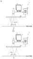
まず、図1を参照して、本発明が適用される場面の一例について説明する。図1は、本実施の形態に係る画像検査装置1を模式的に示す図である。
<A. Application example>
First, an example of a situation in which the present invention is applied will be described with reference to FIG. FIG. 1 is a diagram schematically showing an
本実施の形態に係る画像検査装置1は、工業製品の生産ラインなどにおいて、対象物(以下、「ワークW」とも称す。)を照明しながら撮影し、得られた撮影画像を用いてワークWの外観検査(傷、汚れ、異物などの検査)を行う装置に適用される。画像検査装置1は、ワークWによって反射された光を検出することで検査するものである。そのため、ワークWには、光を反射する表面を有するものが適用可能である。
The
一例としてワークWは、光を拡散反射させる表面を有する。光を拡散反射させる材質としては、たとえば樹脂あるいは金属である。なお、ワークWの表面全体が光を拡散反射するものであると限定する必要はない。光が照射される部分のみがその光を拡散反射させるのでもよい。また、本実施形態が適用可能であれば、ワークWの材質を樹脂あるいは金属に限定する必要はない。 As an example, the work W has a surface that diffuses and reflects light. The material that diffuses and reflects light is, for example, resin or metal. It is not necessary to limit the entire surface of the work W to diffuse and reflect light. Only the portion irradiated with the light may diffusely reflect the light. Further, if the present embodiment is applicable, it is not necessary to limit the material of the work W to resin or metal.
画像検査装置1は、撮像部の一例であるカメラ10と、照明部の一例である照明装置20と、カメラ10と照明装置20とを制御するように構成された制御部の一例である制御装置100とを備える。
The
カメラ10は、対象物であるワークWを撮影して、ワークWの撮影画像を作成するものである。
The
照明装置20は、カメラ10とワークWとの間に配置されており、ワークWに向けて光を照射する発光面を有する。照明装置20は、その発光面における発光位置および光の照射方向を制御可能に構成される。
The
さらに照明装置20は透光性を有している。カメラ10は、ワークWを照明装置20越しに撮影する。照明装置20は、カメラ10が照明装置20を通してワークWを撮像することが出来る程度の透光性を有していればよい。
Further, the
照明装置20は、制御装置100からの指示に従って、光の照射方向および照明パターンを変更することができる。さらに、照明装置20は、制御装置100からの指示に従って、ワークWの表面上で光が走査されるように光を照射する。この際に、カメラ10はワークWを撮像して複数の撮影画像を取得する。
The
制御装置100は、照明装置20の1回目の走査において、照明装置20に第1の方向からワークWに光を照射させる。さらに、制御装置100は、照明装置20の発光面における発光位置を変化させることによって光を走査させる。たとえば1回目の走査では、照明装置20は、カメラ10の光軸11(光学中心)に対して所定の角度をなす方向から光をワークWに照射するとともに、その光を+X方向に走査する。光が走査される間に、制御装置100は、カメラ10にワークWを複数回撮像させる。これによりカメラ10は、複数の撮影画像3を作成する。
The
制御装置100は、照明装置20の2回目の走査において、照明装置20は、1回目の走査のときの照射方向とは異なる方向からワークWに光を照射させる。さらに、制御装置100は、照明装置20の発光面における発光位置を変化させることによって光を走査させる。たとえば2回目の走査では、照明装置20は、1回目の走査のときの照射方向と反対の方向から光をワークWに照射するとともに、その光を−X方向に走査する。1回目の走査と同様に、光が走査される間に、制御装置100は、カメラ10にワークWを複数回撮像させる。これによりカメラ10は、複数の撮影画像5を作成する。
In the second scan of the
制御装置100は、1回目の走査および2回目の走査の際に撮像されたワークWの画像(複数の撮影画像3および複数の撮影画像5)から、ワークWの表面の測定点が照明されるときの照明装置20の発光位置を特定する。「測定点」とは、発光面からの距離を測定すべきワークWの表面上の位置である。制御装置100は、特定された発光位置、および、1回目の走査時の光の照射方向(第1の方向)および2回目の走査時の光の照射方向(第2の方向)に基づいて、照明装置20の発光面から測定点までの距離を算出する。
The
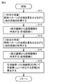
図2は、図1に示した制御装置による処理を説明するための模式図である。図2に示すように、制御装置100は、複数の撮影画像から処理画像を作成する。複数の撮影画像の各々は、二次元に配置された複数の画素を有する。したがって、画素位置ごとに、撮影画像の数と同数の画素が得られる。制御装置100は、それら複数の画素から、1つの画素を選択して処理画像を作成する。
FIG. 2 is a schematic diagram for explaining the processing by the control device shown in FIG. As shown in FIG. 2, the
1回目の走査では、複数の撮影画像3から、ワークWの測定点を照明するための発光位置である第1の発光位置に関する情報を有する処理画像4が作成される。画素位置(x,y)に位置する画素PX1は、複数の撮影画像3の各々の同一の画素位置(x,y)にある画素から選択された画素である。画素PX1は、第1の発光位置に関する情報を画素値として有する。
In the first scan, a processed
2回目の走査では、複数の撮影画像5から、ワークWの測定点を照明するための発光位置である第2の発光位置に関する情報を有する処理画像6が作成される。画素位置(x,y)に位置する画素PX2は、複数の撮影画像5の各々の同一の画素位置(x,y)にある画素から選択された画素である。画素PX2は、第2の発光位置に関する情報を画素値として有する。処理画像6内の画素PX2の位置(x,y)は、処理画像4内の画素PX1の中の画素位置(x,y)と同じである。
In the second scan, a processed
制御装置100は、処理画像4および処理画像6に基づいて、照明装置20からワークWまでの距離を画素ごとに算出する。具体的には、制御装置100は、処理画像4の画素PX1に含まれる第1の発光位置の情報、処理画像6の画素PX2に含まれる第2の発光位置の情報、1回目の走査および第2の走査の際の光の照射方向(第1の方向および第2の方向)に基づいて、照明装置20の発光面から、ワークWの表面の位置(測定点)までの距離を算出する。制御装置100は、その算出した距離を画素値として有する画素PXを含む距離画像7を作成する。
The
このように、照明装置20からワークWの表面までの距離を算出するために、処理画像4の画素PX1が有する情報と、処理画像6において画素PX1と同一の位置にある画素PX2に含まれる情報とを用いる。照明装置20から発せられる光の照射方向、および照明装置20における発光の位置は制御可能である。したがって制御装置100は、発光位置および照射方向に関する情報を有することができる。
In this way, in order to calculate the distance from the
照明装置20の中心点から発光位置までの距離は予め分かっているので、照明装置20に対するカメラ10の位置は特に限定されない。すなわち撮像部の光軸に対する特定の位置に照明装置を配置する必要がない。したがって撮像部と照明装置との間のキャリブレーションを不要としながら対象物の検査を行うことが可能な画像検査装置および画像検査方法を提供することができる。
Since the distance from the center point of the
<B.画像検査装置が適用される生産ラインの一例>
次に、図3を参照しながら、画像検査装置1が適用される生産ラインの一例を説明する。図3は、本実施の形態に係る画像検査装置1が適用される生産ラインの一例を示す模式図である。画像検査装置1は、工業製品の生産ラインなどにおいて、制御装置100の制御によって照明装置20でワークWを照明しながらカメラ10で撮影し、得られた撮影画像を用いてワークWの外観検査を行う。具体的には、検査対象となるワークWは、移動可能なステージ300によって、カメラ10および照明装置20が固定された検査位置まで移動する。ワークWは、検査位置まで移動すると、画像検査装置1による外観検査が終了するまでその場で停止する。このとき、制御装置100は、照明装置20によってワークWを照明しながらカメラ10でワークWを撮影し、撮影画像をモニタに表示する。これにより、作業者は、モニタ画面に表示された撮影画像の色を見ながらワークWの外観を検査する。もしくは、制御装置100は、撮影画像に対して所定の画像処理を行ない、画像処理結果に基づいてワークWの異常判定を行なってもよい。
<B. An example of a production line to which image inspection equipment is applied>
Next, an example of a production line to which the
制御装置100は、たとえば、CPU(Central Processing Unit)やMPU(Micro-Processing Unit)などのプロセッサと、RAM(Random Access Memory)と、表示コントローラと、システムコントローラと、I/O(Input Output)コントローラと、ハードディスクと、カメラインターフェイスと、入力インターフェイスと、発光インターフェイスと、通信インターフェイスと、メモリカードインターフェイスとを含む。これらの各部は、システムコントローラを中心として、互いにデータ通信可能に接続される。
The
<C.照明装置の構成の一例>
図4は、画像検査装置1に含まれる照明装置の構成を模式的に示した図である。照明装置20は、ワークWとカメラ10との間に配置され、ワークWに向けて光を照射するとともに、透光性を有している。そのため、照明装置20から放射された光は、ワークWで反射し、照明装置20を透過して、カメラ10に到達する。
<C. An example of the configuration of a lighting device>
FIG. 4 is a diagram schematically showing a configuration of a lighting device included in the
照明装置20は、面光源30と、光学系の一例であるマイクロレンズアレイ40とを含む。面光源30は、ワークW側の発光面35からワークWに向けて光を放射する。面光源30の発光面35のうち、マトリクス状に配置された複数の発光領域から光が放射される。ワークWからの反射光は、面光源30のうち発光領域以外の透光領域を透過する。
The
各発光領域は、発光部31を含む。一例では、発光部31は、有機エレクトロルミネッセンス(以下、有機ELと呼ぶ)により構成された部材を含む。複数の発光部31は、選択的に発光可能に構成されている。発光すべき発光部31は、制御装置100(図1を参照)によって選択される。一例として面光源30は、有機ELを用いた光源である。しかし、透過性を有する照明装置であって、マトリクス状に配列され選択的に発光可能に構成された複数の発光部を有する照明装置であれば、この実施の形態に適用可能である。すなわち本実施の形態に適用可能な照明装置20は、有機ELを用いた光源に限定されるものではない。
Each light emitting region includes a
マイクロレンズアレイ40は、面光源30の発光面35に対向して配置される。マイクロレンズアレイ40は、複数の発光部31にそれぞれ対向して設けられた複数のレンズ41を含む。一例では、レンズ41は凸レンズである。レンズ41は、対応する発光部31から発せられる光を所望の方向に導くように構成される。すなわち、マイクロレンズアレイ40は、複数の発光部31の各々から発せられる光の照射方向を、各発光部31の位置に対応した方向に制御するように構成されている。
The
複数の発光部31の中から発光させるべき発光部を選択することによって、照射立体角を任意に変更することができる。発光させるべき発光部は、視野の場所に応じて選択される。したがって、視野の場所ごとに照射立体角を任意に設定可能な画像検査装置1を実現できる。さらに、照射立体角を任意に変更することができるので、たとえばスリットあるいはハーフミラーといった光学部品を不要とすることができる。したがって照明装置20を小型化することができる。したがって、視野の場所ごとに照射立体角を設定可能であるとともに、小型化が可能な画像検査装置1を実現できる。
The irradiation solid angle can be arbitrarily changed by selecting a light emitting unit to be emitted from the plurality of light emitting
図5および図6を参照して、本実施の形態に係る照明装置の構成の一例を説明する。図5は、本実施の形態に係る照明装置の一例の一部断面を示す模式図である。図6は、本実施の形態に係る照明装置の一部を拡大した模式平面図である。 An example of the configuration of the lighting device according to the present embodiment will be described with reference to FIGS. 5 and 6. FIG. 5 is a schematic view showing a partial cross section of an example of the lighting device according to the present embodiment. FIG. 6 is an enlarged schematic plan view of a part of the lighting device according to the present embodiment.
照明装置20は、透過型のシート照明装置であり、面光源30とマイクロレンズアレイ40とを含む。面光源30は、有機ELを用いた光源である。面光源30は、発光面35に沿ってマトリクス状に配列された複数の発光部を含む。図5には、発光部31A〜31Eが代表的に示されている。
The illuminating
各々の発光部31A〜31Eは、対向する一対の電極(図示せず)を有する。一対の電極間に電圧が印加されることにより、これらの発光部は発光する。複数の電極対の中から電圧が印加されるべき電極対を選択することによって、発光すべき発光部を選択することができる。発光部31A〜31Eの各々が発する光の色は限定されない。たとえば複数の発光部31は同色の光を発するのでもよい。あるいは、赤色光を発する発光部と、緑色光を発する発光部と、青色光を発する発光部とを組み合わせることにより、光の色を異ならせることができる発光部を実現することができる。
Each
マイクロレンズアレイ40は、複数の発光部31にそれぞれ対向して配置された複数のマイクロレンズである、複数のレンズ41を含む。複数のレンズ41は、発光面35に沿ってマトリクス状に配置される。図5には、発光部31A〜31Eにそれぞれ対向するレンズ41A〜41Eが代表的に示されている。一例ではレンズ41A〜41Eの各々は、平凸レンズである。平凸レンズの平面は発光面35に向けられている。たとえば平凸レンズは半球レンズであってもよい。
The
各々のレンズは、対応する発光部から発せられる光の照射方向を制御するためのものである。一実施形態では、レンズ41A〜41Eの間では、発光部の光軸に対するレンズの光軸の相対的な位置が異なっている。発光部の光軸に対するレンズの光軸のずれの方向およびずれ量に従って、レンズから出射される光の方向が決定される。なお、この実施の形態において、発光部の光軸とは、発光領域の中心点を通り発光領域に対して垂直な軸を意味し、レンズの光軸とは、レンズの中心を通り、レンズの主面に対して垂直な軸を意味する。「ずれ量」とは、発光部の光軸に対するレンズの光軸のずれの大きさを意味する。
Each lens is for controlling the irradiation direction of the light emitted from the corresponding light emitting unit. In one embodiment, the relative positions of the optical axis of the lens with respect to the optical axis of the light emitting portion are different between the
発光部31Cの光軸32Cと、レンズ41Cの光軸42Cとは実質的に一致している。発光部31Aの光軸32Aに対して、レンズ41Aの光軸42Aは、紙面右方向(+X方向)にずれている。同様に、発光部31Bの光軸32Bに対して、レンズ41Bの光軸42Bも+X方向にずれている。発光部31Aおよびレンズ41Aの対のほうが、発光部31Bおよびレンズ41Bの対よりも、ずれ量が大きい。
The
一方、発光部31Dの光軸32Dに対して、レンズ41Dの光軸42Dは、紙面左方向(−X方向)にずれている。同様に、発光部31Eの光軸32Eに対して、レンズ41Eの光軸42Eも−X方向にずれている。発光部31Eおよびレンズ41Eの対のほうが、発光部31Dおよびレンズ41Dの対よりも、ずれ量が大きい。
On the other hand, the
図5から理解されるように、図5に示す発光部31A〜発光部31Eのいずれかを選択的に発光させることにより、照射立体角を異ならせることができる。照射立体角を異ならせることが可能であるので、照明装置20の照明のパターンの制約が小さくなる。言い換えると、任意のパターンに従う照明を照明装置20によって実現することができる。
As can be understood from FIG. 5, the irradiation solid angle can be made different by selectively emitting light from any of the
図6に示すように、照明装置20は、マトリクス状に配置された複数の照明要素21を含む。すなわち照明装置20は、複数の照明要素21に区画される。各々の照明要素21は、複数の発光部31および複数のレンズ41を含む。たとえば各々の照明要素21は、図5に示す発光部31A〜発光部31Eおよびレンズ41A〜41Eを含むことができる。図示の都合上、図6では、各々の照明要素21に含まれる1つの発光部31および、対応する1つのレンズ41が示される。
As shown in FIG. 6, the
各々の照明要素21は、発光領域と透明領域とを含む。発光領域を発光させることによって照明要素21全体を発光させることができる。一方、各照明要素21は、透明領域を備えることによって、透光性を有する。
Each illuminating
照明装置20は、複数の照明要素21を互いに独立に点灯させることができる。複数の照明要素21のうち、発光されるべき発光部31を含む照明要素21(すなわち、点灯させるべき照明要素21)によって、照明装置20による照明パターンが決定される。各照明要素21から照射される光の波長を変えることができる照明装置20においては、照明パターンは、複数の照明要素21のうちの点灯させる照明要素21と、点灯させる各照明要素21から照射させる光の波長とによって決定されてもよい。
The
図7は、照明装置20の構成要素である照明要素の構造の一例を模式的に示した平面図である。図7では、撮像部側(照明装置20の上方)からの照明要素の平面視図が示されている。
FIG. 7 is a plan view schematically showing an example of the structure of the lighting element which is a component of the
照明要素21は、マトリクス状に配置された複数のセル22を含む。以下の説明では「行」はX方向を意味し、「列」はY方向を意味する。図5では、5行5列(=5×5)に配置された25個のセル22からなる照明要素21が示されている。しかし、照明要素21を構成するセル22の個数は特に限定されない。たとえば照明要素21は、11行11列(=11×11)に配置された121個のセル22によって構成されてもよい。セル22の個数が多いほど、照明要素21の照射方向の分解能を向上させることができる一方で発光位置の分解能が低下する。照明要素21を構成するセル22の個数は、照射方向の分解能と発光位置の分解能とから決定することができる。
The
各々のセル22は、発光部31と、レンズ41と、透明領域24とを含む。発光部31の発光面は、セル22において発光領域を構成する。
Each
複数の発光部31は、第1のピッチP1でX方向およびY方向に配置される。複数のレンズ41は、第2のピッチP2でX方向およびY方向に配置される。第2のピッチP2が第1のピッチP1よりも小さい(P2<P1)ので、X方向(行方向)に沿って並べられた複数のセル22について、発光部31の光軸32とレンズ41の光軸42との間のX方向のずれ量が、公差(P1−P2)の等差数列に従う。同様に、Y方向(列方向)に沿って並べられた複数のセル22について、発光部31の光軸32とレンズ41の光軸42との間のY方向のずれ量が公差(P1−P2)の等差数列に従う。
The plurality of light emitting
複数の発光部31および複数のレンズ41は、X軸およびY軸の両方に対して対称に配置される。このことを説明するために、図7に対称軸25,26が示される。対称軸25は、複数の発光部31および複数のレンズ41が、X軸に対して対称に配置されることを示すための軸であり、Y方向に平行である。対称軸26は、複数の発光部31および複数のレンズ41が、Y軸に対して対称に配置されることを示すための軸であり、X方向に平行である。
The plurality of light emitting
図7において、セル22Cは、照明要素21の中心に位置するセルである。セル22Cは、発光部31Cとレンズ41Cとを含む。発光部31Cの光軸32Cとレンズ41Cの光軸42Cとは平面視において重なる。すなわち、光軸32Cと光軸42Cとの間では、X方向のずれ量およびY方向のずれ量は、ともに0である。なお、光軸32C,42Cは、対称軸25,26の交点に位置する。
In FIG. 7, cell 22C is a cell located at the center of the
照明要素21内の各セルにおいて、発光部31の光軸32とレンズ41の光軸42との間のX方向のずれ量およびY方向のずれ量は、そのセルと、中央のセル22Cとの間のX方向の距離およびY方向の距離に従って決定される。これにより、セル22ごとに光の照射方向を異ならせることができる。照明要素21は、複数の方向からワークに光を照射することができる。さらに、複数のセルのうち、点灯させるセルを選択することによって、照明要素21からの光の照射方向を制御することができる。
In each cell in the
図7に示した構造では、X方向とY方向とで発光部31のピッチおよびレンズ41のピッチが同じである。しかしながら、X方向とY方向とで発光部31のピッチを異ならせてもよい。同様にX方向とY方向とでレンズ41のピッチを異ならせてもよい。
In the structure shown in FIG. 7, the pitch of the
発光部31の光軸32に対するレンズ41の光軸42のずれ量(変位量)が大きい場合、発光部31から出射された光の一部がレンズ41の周囲から漏れる可能性がある。図8は、レンズ41の周囲から漏れる光の対策のための構成を示す模式平面図である。図9は、図8に示された構成の模式断面図である。図8および図9に示されるように、レンズ41の周辺を囲むように遮光部44が設けられてもよい。遮光部44は光を通さない部材、あるいは光を減衰させる部材からなる。遮光部44によって、発光部31からの光が意図しない方向に漏れる可能性を低減することができる。
When the amount of deviation (displacement) of the
図10は、図8に示された構成の1つの変形例を示した模式平面図である。図10に示された例では、図8に示された構成に比べて、遮光部44の面積が大きい。これにより、発光部31からの光が意図しない方向に漏れる可能性をさらに低減することができる。
FIG. 10 is a schematic plan view showing one modification of the configuration shown in FIG. In the example shown in FIG. 10, the area of the light-shielding
図11は、図8に示された構成の別の変形例を示した模式断面図である。図11に示された例では、遮光部44は、図10に示した構成に加えて、レンズ41の高さ(厚み)方向に沿った十分な高さでレンズ41の周囲を囲む構成を有する。図10に示された構成によれば、レンズ41の周囲から漏れる光を低減する効果をさらに高めることができる。
FIG. 11 is a schematic cross-sectional view showing another modified example of the configuration shown in FIG. In the example shown in FIG. 11, in addition to the configuration shown in FIG. 10, the light-shielding
<D.実施の形態1>
実施の形態1では、光切断法を用いてワークの表面が検査される。照明装置20は、ある方向からワークWに対してライン状の光を照射するとともに、その光を走査する。カメラ10は、光が走査される間にワークWを複数回撮像することにより、複数の撮影画像を作成する。上述の通り、光の走査は2回実行される。
<
In the first embodiment, the surface of the work is inspected using a photocutting method. The
図12は、光切断法を実施する際における光の1回目の走査を説明するための図である。図13は、図12に示す光照射のための照明装置の照明パターンを説明するための図である。図13および、以下に説明される図に示した照明要素21の構成は、基本的に図5に示された構成と同じであるので、詳細な説明は繰り返さない。なお、以下に説明する図では、照明装置20において発光している領域および、照明要素において発光している発光部をハッチングによって示す。
FIG. 12 is a diagram for explaining the first scanning of light when the light cutting method is performed. FIG. 13 is a diagram for explaining an illumination pattern of the illumination device for light irradiation shown in FIG. Since the configuration of the
図12に示されるように、照明装置20は、カメラ10の光軸11に対して角度θをなす方向から、ライン状の光LTをワークWに照射し、かつ、その光LTを+X方向に走査する。光LTが走査される間に、カメラ10は、ワークWの表面を複数回撮像する。これにより複数の撮影画像が取得される。
As shown in FIG. 12, the
図13には、光の走査中における照明装置20の1つの状態が示されている。図13に示した直線L1は、カメラ10の光軸のX座標を示すための仮想的な直線であり、Y軸に平行な直線である。照明装置20は、Y方向に沿って並ぶ複数の照明要素21を点灯させる。一例として、図13は、直線L1から距離d1だけ−X方向に離れた位置する複数の照明要素21が点灯する状態を示す。所定方向からワークWに光を照射するために、複数の照明要素21の各々では、特定の列(たとえば列C2)に配置された3つの発光部31が発光する。これにより、照明装置20は、カメラ10の光軸11に対して角度θの方向から、Y方向に沿ったライン状の光を、ワークWの表面の所望の場所に照射することができる。
FIG. 13 shows one state of the illuminating
図14は、光切断法を実施する際における光の2回目の走査を説明するための図である。図15は、図14に示す光照射のための照明装置の照明パターンを説明するための図である。図14に示されるように、2回目の走査では、照明装置20は、1回目の走査における光の照射方向とは逆の方向からワークWにライン状の光LTを照射する。光の照射される方向は、カメラ10の光軸11に対して角度θをなす。
FIG. 14 is a diagram for explaining a second scan of light when performing the optical cutting method. FIG. 15 is a diagram for explaining an illumination pattern of the illumination device for light irradiation shown in FIG. As shown in FIG. 14, in the second scan, the illuminating
照明装置20は、光LTをたとえば−X方向に走査する。しかし1回目の走査と同じく、照明装置20は光LTを+X方向に走査してもよい。光LTが走査される間にカメラ10は、ワークWの表面を複数回撮像する。これにより複数の撮影画像が取得される。
The illuminating
一例として、図15は、直線L1から距離d2だけ+X方向に離れた位置する複数の照明要素21が点灯する状態を示す。複数の照明要素21の各々では、特定の列(たとえば列C4)に配置された3つの発光部31が発光する。図13および図15の比較から理解されるように、列C4と、列C2とを比較すると、発光部31およびレンズ41が対称軸25に対して対称に配置される。したがって、照明装置20は、1回目の走査における光の照射方向とは逆の方向、かつカメラ10の光軸11に対して角度θをなす方向から、Y方向に沿ったライン状の光を、ワークWの表面の所望の場所に照射することができる。
As an example, FIG. 15 shows a state in which a plurality of
図16は、実施の形態1に係る検査方法に含まれる距離算出方法を示したフローチャートである。図2および図16を参照することにより実施の形態1に係る距離算出方法を以下に説明する。ステップS1において、照明装置20は1回目の光の走査を行うとともに、カメラ10がワークWをn(nは2以上の整数)回撮像する。これによりn枚の画像(n枚の撮影画像3)が取得される。
FIG. 16 is a flowchart showing a distance calculation method included in the inspection method according to the first embodiment. The distance calculation method according to the first embodiment will be described below with reference to FIGS. 2 and 16. In step S1, the
ステップS2において、制御装置100は、ステップS1の処理によって得られたn枚の画像から、処理画像4を作成する。具体的には、制御装置100は、画素位置(x,y)ごとに、n枚の撮像画像の中から、輝度が最大となる画素を特定する。そして、制御装置100は、その画像が得られたときの距離d1(図12および図13を参照)を、画素の情報に含める。距離d1は、ワークWの表面上の測定点に対応する画素(画素位置(x,y)の画素)の輝度が最大となるときの照明装置20の第1の発光位置を表す。処理画像4内の各画素は、最も高い輝度の値を与える距離d1の情報を画素値として有する。なお、図16では、処理画像4を「d1画像」と呼ぶ。
In step S2, the
ステップS3において、照明装置20は2回目の光の走査を行うとともに、カメラ10がワークWをn回撮像する。これによりn枚の画像が取得される。ステップS4において、制御装置100は、ステップS3の処理によって得られたn枚の画像(n枚の撮影画像5)から、処理画像6を作成する。
In step S3, the
ステップS4において、制御装置100は、ステップS3の処理によって得られたn枚の画像(n枚の撮影画像5)から、処理画像6を作成する。ステップS2の処理と同様に、制御装置100は、画素位置(x,y)ごとに、n枚の撮像画像の中から、輝度が最大となる画素を特定する。そして、制御装置100は、その画像が得られたときの距離d2(図14および図15を参照)を、画素の情報に含める。距離d2は、ワークWの表面上の測定点に対応する画素(画素位置(x,y)の画素)の輝度が最大となるときの照明装置20の第2の発光位置を表す。処理画像6内の各画素は、最も高い輝度の値を与える距離d2の情報を画素値として有する。なお、図16では、処理画像6を「d2画像」と呼ぶ。
In step S4, the
ステップS5では、制御装置100は、d1画像(処理画像4)とd2画像(処理画像6)とを用いて、各座標(x,y)の画素に対応する距離Dを算出する。距離Dは、照明装置20の発光面35から、座標(x,y)の画素に対応するワークWの表面上の測定点までの距離である。
In step S5, the
図17は、実施の形態1に係る距離算出方法の原理を説明した図である。図17において、測定点13は、座標(x,y)の画素に対応するワークWの表面上の位置に対応する。処理画像4(d1画像)における画素PX1、および処理画像6(d2画像)における画素PX2は、測定点13に対応した画素である。
FIG. 17 is a diagram illustrating the principle of the distance calculation method according to the first embodiment. In FIG. 17, the
直線12は、測定点13を通り、照明装置20の中心線28(発光面35の中心を通り、発光面35に垂直な直線)に平行な直線である。照明装置20の中心線28と直線12との間の距離をdとすると、以下の式(1)および式(2)が成立する。
The
(d1−d)=D×tanθ (1)
(d2+d)=D×tanθ (2)
式(1)および式(2)からdを消去すると、以下の式(3)が成立する。
(D1-d) = D × tan θ (1)
(D2 + d) = D × tan θ (2)
When d is deleted from the equations (1) and (2), the following equation (3) is established.
(d1+d2)=2D×tanθ (3)
式(3)を変形すると、以下の式(4)が導かれる。
(D1 + d2) = 2D × tanθ (3)
By transforming equation (3), the following equation (4) is derived.
D=(d1+d2)/(2×tanθ) (4)
θは照明装置20からの光の出射方向である。制御装置100は、照明装置20を制御することによって照明装置20から光が出射される方向を制御する。したがって制御装置100は、角度θの値を知ることができる。距離d1,d2は、それぞれ、処理画像4の画素および処理画像6の画素が有する情報であり、照明装置20による光の走査の条件から決定される。
D = (d1 + d2) / (2 × tanθ) (4)
θ is the emission direction of light from the
式(4)には距離dが含まれないので、ワークWの表面上の任意の位置について、式(4)が成立する。式(4)を用いることによって、距離d1(第1の発光位置)、距離d2(第2の発光位置)、角度θ(光の照射方向)に基づいて、照明装置20の発光面35からワークWの表面上の任意の位置までの距離Dを算出することができる。
Since the distance d is not included in the equation (4), the equation (4) holds for any position on the surface of the work W. By using the formula (4), the work is formed from the
距離d1,d2の各々は、発光面35の中心からの距離である。複数の照明要素21がマトリクス状に配置されているので、距離d1,d2を決定することができる。したがって、撮像部と照明装置との間のキャリブレーションを不要としながら対象物の検査を行うことが可能となる。
Each of the distances d1 and d2 is a distance from the center of the
照明パターンを走査する際に、発光面における発光領域の一方の端から他方の端までの範囲を走査してもよい(全走査)。しかしながら距離を求めたい箇所が限定される場合は走査範囲を限定させることも可能である。 When scanning the illumination pattern, the range from one end to the other end of the light emitting region on the light emitting surface may be scanned (full scan). However, it is also possible to limit the scanning range when the location where the distance is desired is limited.
角度θが小さい場合には、三角測距の原理上、距離の精度が低下する一方で、オクルージョン(遮蔽)のリスクが小さい。逆に、角度θの値が大きい場合、距離の精度が向上するものの、オクルージョンのリスクが大きい。したがって光の照射方向を定める角度θの値は、ワークの形状に応じて変化させても良い。角度θの値を変化させながら複数回の試行を行い、その結果を統合してもよい。 When the angle θ is small, the accuracy of the distance is lowered due to the principle of triangular distance measurement, but the risk of occlusion (occlusion) is small. On the contrary, when the value of the angle θ is large, the accuracy of the distance is improved, but the risk of occlusion is large. Therefore, the value of the angle θ that determines the light irradiation direction may be changed according to the shape of the work. Multiple trials may be performed while changing the value of the angle θ, and the results may be integrated.
以上の説明では、走査の方向がX方向であるが、Y方向の走査も実行可能である。上述の説明において、X方向(X軸)をY方向(Y軸)に置き換えるとともに、対称軸25を対称軸26に置き換えればよい。X方向の走査による測定とY方向の走査による測定とを試行して、それらの結果を統合してもよい。
In the above description, the scanning direction is the X direction, but scanning in the Y direction can also be performed. In the above description, the X direction (X axis) may be replaced with the Y direction (Y axis), and the
また、上記の説明では、照明要素21の1列に含まれる5個の発光部31のうち3個が点灯する。しかし、1列に含まれる全ての(5個の)発光部31を発光させてもよい。あるいは1列の中央に位置する1つの発光部31のみを発光させてもよい。
Further, in the above description, three of the five light emitting
<E.実施の形態2>
実施の形態2では、位相シフト法を用いてワークの表面が検査される。照明装置20は、ある方向からワークWに対して縞パターンの光を照射するとともに、その光を走査する。カメラ10は、光が走査される間にワークWを複数回撮像することにより、複数の撮影画像を作成する。実施の形態1と同様に、光の走査は2回実行される。
<E. Embodiment 2>
In the second embodiment, the surface of the work is inspected using the phase shift method. The illuminating
図18は、位相シフト法を実施する際における光の1回目の走査を説明するための図である。図19は、図18に示す光照射のための照明装置の照明パターンを説明するための図である。図18に示すように、照明装置20は、カメラ10の光軸11に対して角度θをなす方向から、ワークWに光LTを照射する。カメラ10は、ワークWの表面を撮像する。照明装置20は、縞パターン(明暗パターン)の光を、縞パターンの位相を変化させながらワークWに照射する。これにより、縞パターンの光をワークの表面上で走査するのと等価な状態を発生させることができる。照明パターンは周期的なパターンであるため、照明装置20は、位相を1周期分変化させるだけでよい。図18に示す例では、照明パターンが+X方向に走査される。
FIG. 18 is a diagram for explaining the first scanning of light when the phase shift method is performed. FIG. 19 is a diagram for explaining an illumination pattern of the illumination apparatus for light irradiation shown in FIG. As shown in FIG. 18, the
図19に示されるように、照明装置20は、X方向に沿って明暗が交互に生じるように、複数の列の照明要素21を点灯させる。Lは縞パターンの周期に対応する長さを表す。なお、発光の強度が正弦波に従って変化するように、照明装置20を制御してもよい。所定方向からワークWに光を照射するために、複数の照明要素21の各々では、特定の列(たとえば列C2)に配置された3つの発光部31が発光する。
As shown in FIG. 19, the illuminating
図20は、位相シフト法を実施する際における光の2回目の走査を説明するための図である。図21は、図20に示す光照射のための照明装置の照明パターンを説明するための図である。図20に示されるように、2回目の走査では、照明装置20は、1回目の走査における光の照射方向とは逆の方向から光LTをワークWに照射する。光の照射される方向は、カメラ10の光軸に対して角度θをなす。
FIG. 20 is a diagram for explaining a second scan of light when the phase shift method is performed. FIG. 21 is a diagram for explaining an illumination pattern of the illumination device for light irradiation shown in FIG. As shown in FIG. 20, in the second scan, the illuminating
照明装置20は、光LTをたとえば−X方向に走査する。しかし1回目の走査と同じく、照明装置20は光LTを+X方向に走査してもよい。光LTが走査される間にカメラ10は、ワークWの表面を複数回撮像する。
The illuminating
一例として、複数の照明要素21の各々では、特定の列(たとえば列C4)に配置された3つの発光部31が発光する。実施の形態1における例と同様に、照明装置20は、1回目の走査における光の照射方向とは逆の方向、かつカメラ10の光軸11に対して角度θをなす方向から、光を照射することができる。
As an example, in each of the plurality of
図22は、実施の形態2に係る検査方法に含まれる距離算出方法を示したフローチャートである。図2および図22を参照することにより、実施の形態2に係る距離算出方法を以下に説明する。ステップS11において、照明装置20は1回目の光の走査を行う。すなわち照明装置20は、照明パターンの位相を、たとえば1周期分、変化させる。位相の変化分は特に限定されない。カメラ10がワークWをn(nは2以上の整数)回撮像する。これによりn枚の画像が取得される。
FIG. 22 is a flowchart showing a distance calculation method included in the inspection method according to the second embodiment. The distance calculation method according to the second embodiment will be described below with reference to FIGS. 2 and 22. In step S11, the illuminating
ステップS12において、制御装置100は、ステップS11の処理によって得られたn枚の画像(n枚の撮影画像3)から、照明パターン(縞パターン)の位相αを画素値とする処理画像4を作成する。
In step S12, the
たとえば照明装置20の発光面(発光面35)において、正弦波パターンに従って発光しているとする。この場合、正弦波の極大点は照明強度の最大値を表し、正弦波の極小点は照明強度の最小値を表し、正弦波の極大点および極小点の中間点は、照明強度の中間値を表す。なお、図22では、処理画像4を「位相画像1」と呼ぶ。
For example, it is assumed that the light emitting surface (light emitting surface 35) of the
図23は、照明パターンの位相を求める方法を説明するための模式図である。図23に示されるように、発光面35から光が照射方向に沿って照射されたとき、発光面35上のある点A1と、ワークWの表面上の点B1とが対応づけられる。たとえば発光パターンの位相を90°ずつ変化させながら、ワークWの表面をカメラ10により撮影して、画素の輝度値(濃度値)を記録する。この場合、画素の輝度値を表す4点が得られる。次に、この4点に対して正弦波をフィッティングする。基準波がsin(x)である場合に、フィッティングされた正弦波がsin(x−a)で表されるとする。この場合、値aが位相である。すなわち、照明パターンの位相を求める方法とは、基準波からの位相差を求める方法である。ワークWの表面上の点B2に対しても、同様の方法により、位相が求められる。
FIG. 23 is a schematic diagram for explaining a method of obtaining the phase of the illumination pattern. As shown in FIG. 23, when light is emitted from the
なお、輝度値は誤差を有する。したがって、位相の変化を小さくするほど輝度値を表す点の数が多くなるため、より精度よく位相を求めることができる。 The brightness value has an error. Therefore, as the change in phase is made smaller, the number of points representing the luminance value increases, so that the phase can be obtained more accurately.
図22に戻り、ステップS13において、照明装置20は2回目の光の走査を行うとともに、カメラ10がワークWをn回撮像する。これによりn枚の画像が取得される。ステップS14において、制御装置100は、ステップS13の処理によって得られたn枚の画像(n枚の撮影画像5)から、照明パターンの位相βを画素値とする処理画像6を作成する。ステップS13の処理は、ステップS12の処理と同様である(図23を参照)。なお、図22では、処理画像6を「位相画像2」と呼ぶ。
Returning to FIG. 22, in step S13, the
ステップS15では、制御装置100は、位相画像1(処理画像4)と位相画像2(処理画像6)とを用いて、各座標(x,y)の画素に対応する距離Dを算出する。
In step S15, the
図24は、実施の形態2に係る距離算出方法の原理を説明した図である。実施の形態2においても同様に式(4)が成立する。距離d1,d2は、それぞれ以下の式(5)および式(6)に従って表される。 FIG. 24 is a diagram illustrating the principle of the distance calculation method according to the second embodiment. Similarly, the equation (4) holds in the second embodiment. The distances d1 and d2 are expressed according to the following equations (5) and (6), respectively.
d1=L×sinα (5)
d2=L×sinβ (6)
Lは縞パターンの縞の周期であるので、既知の値である。位相α,βはそれぞれ、処理画像4の画素および処理画像6の画素が有する画素値(位相の値)である。したがって、式(4)に式(5)および式(6)を代入することによって、距離Dを算出することができる。なお、周期固定の縞パターンを用いた場合、位相シフト法において算出できるのは、絶対距離ではなく、発光面35に平行な仮想平面50からの相対距離である。実施の形態2において、距離Dは、この相対距離である。図24では1つの仮想平面(仮想平面50)を示しているが、仮想平面は、発光面35に平行であり、かつ、一定間隔で複数の候補が存在する。
d1 = L × sinα (5)
d2 = L × sinβ (6)
Since L is the period of the stripes of the stripe pattern, it is a known value. The phases α and β are pixel values (phase values) of the pixels of the processed
<F.照明装置の構成の変形例>
図25は、変形例1に係る照明装置120の一部断面を示す模式図である。図3に示す照明装置20と比較して、照明装置120は、マイクロレンズアレイ40に替えてマイクロレンズアレイ140を備える。マイクロレンズアレイ140は、複数の発光部31にそれぞれ対向して配置された複数のマイクロレンズである、複数のレンズ141を含む。図25には、発光部31A〜31Eにそれぞれ対向するレンズ141A〜141Eが代表的に示されている。
<F. Modification example of the configuration of the lighting device>
FIG. 25 is a schematic view showing a partial cross section of the
レンズ141A〜141Eの各々は、ロッドレンズである。レンズ141A〜141Eの間では、発光部31の光軸(光軸32A〜32E)に対するレンズの光軸(光軸142A〜142E)の角度が異なっている。ロッドレンズの入射面に対する光の入射角度を異ならせることによって、ロッドレンズの出射面から出射される光の出射角度(レンズの光軸に対する角度)を異ならせることができる。したがって、照明装置120では、発光部ごとに光の出射方向を異ならせることができる。ロッドレンズを利用することにより、ワークWの形状の検査を実施可能な、ワークWと照明装置120との間の距離を大きくすることができる。
Each of the
図26は、変形例2に係る照明装置220の一部断面を示す模式図である。図3に示す照明装置20と比較して、照明装置220は、マイクロレンズアレイ40に替えてマイクロレンズアレイ240を備える。マイクロレンズアレイ240は、複数の発光部31にそれぞれ対向して配置された複数のマイクロレンズである、複数のレンズ241を含む。図26には、発光部31A〜31Eにそれぞれ対向するレンズ241A〜241Eが代表的に示されている。
FIG. 26 is a schematic view showing a partial cross section of the
レンズ241A〜241Eの各々は、凹レンズである。図25に示された変形例と同様に、レンズ241A〜241Eの間では、発光部31の光軸に対するレンズの光軸の角度が異なっている。発光部の光軸(光軸32A〜32E)に対するレンズの光軸(光軸242A〜242E)の角度を異ならせることによって、凹レンズから出射される光の出射角度(レンズの光軸に対する角度)を異ならせることができる。
Each of the
図27は、変形例3に係る照明装置320の一部断面を示す模式図である。図3に示す照明装置20と比較して、照明装置320は、マイクロレンズアレイ40に替えてマイクロレンズアレイ340を備える。マイクロレンズアレイ340は、複数の発光部31にそれぞれ対向して配置された複数のマイクロレンズである、複数のレンズ341を含む。図27には、発光部31A〜31Eにそれぞれ対向するレンズ341A〜341Eが代表的に示されている。
FIG. 27 is a schematic view showing a partial cross section of the
変形例3では、図3の構成におけるレンズ41A〜41Eが、レンズ341A〜341Eに置き換えられ、光軸42A〜42Eが、光軸342A〜342Eに置き換えられている。レンズ341A〜341Eの各々は凸レンズである。ただし、レンズ341A〜341Eの各々の形状は、レンズ41A〜41Eの形状とは異なる。図3に示された例と同じく、発光部の光軸(光軸32A〜32E)に対するレンズの光軸(光軸342A〜342E)の相対的な位置を異ならせることにより、発光部から発せられる光の照射方向をレンズによって制御することができる。
In the third modification, the
なお図25および図26に示された照明装置において、照明要素はマトリクス状に配置された複数のセル22を含む。複数のセル22の間では、そのセルの位置に応じて、発光部の光軸に対するレンズの光軸の傾きの角度を異ならせることができる。さらに、X軸に対するレンズの光軸の角度および、Y軸に対するレンズの光軸の角度がセルごとに異なり得る。
In the illuminating apparatus shown in FIGS. 25 and 26, the illuminating element includes a plurality of
また、図25〜図27に示されたマイクロレンズアレイ140,240,340において、レンズの周囲に遮光部44(図8〜図11を参照)を配置してもよい。
Further, in the
<G.付記>
以上のように、本実施の形態は以下のような開示を含む。
<G. Addendum>
As described above, the present embodiment includes the following disclosure.
(構成1)
対象物(W)を撮影する撮像部(10)と、
前記対象物(W)と前記撮像部(10)との間に配置されて、前記対象物(W)に向けて光を照射する発光面(35)を有し、前記発光面(35)における発光位置および前記光の照射方向を制御可能に構成された、透光性の照明部(20,120,220,320)と、
前記撮像部(10)および前記照明部(20,120,220,320)を制御するように構成された制御部(100)とを備え、
前記制御部(100)は、
前記照明部(20,120,220,320)の第1の走査において、前記照明部(20,120,220,320)に第1の方向から前記対象物(W)に光を照射させるとともに、前記発光面(35)における前記発光位置を変化させることにより前記光を走査させて、前記第1の走査の間に、前記撮像部(10)に前記対象物(W)を撮像させ、
前記照明部(20,120,220,320)の第2の走査において、前記照明部(20,120,220,320)に、前記第1の方向とは異なる第2の方向から前記対象物(W)に前記光を照射させるとともに前記発光面(35)における前記発光位置を変化させることにより前記光を走査させ、前記第2の走査の間に前記撮像部(10)に前記対象物(W)を撮像させ、
前記制御部(100)は、前記第1の走査および前記第2の走査の際に撮像された前記対象物(W)の画像から、前記対象物(W)の表面の測定点(13)が照明されるときの前記照明部(20,120,220,320)の前記発光位置を特定し、特定された発光位置、および、前記第1の方向および前記第2の方向に基づいて、前記測定点(13)までの距離を算出する、画像検査装置(1)。
(Structure 1)
An imaging unit (10) that captures an object (W),
A light emitting surface (35) arranged between the object (W) and the imaging unit (10) and irradiating light toward the object (W) is provided on the light emitting surface (35). A translucent illuminating unit (20, 120, 220, 320) configured to be able to control the light emitting position and the irradiation direction of the light, and
A control unit (100) configured to control the image pickup unit (10) and the illumination unit (20, 120, 220, 320) is provided.
The control unit (100)
In the first scan of the illumination unit (20, 120, 220, 320), the illumination unit (20, 120, 220, 320) is made to irradiate the object (W) with light from the first direction, and the object (W) is irradiated with light. The light is scanned by changing the light emitting position on the light emitting surface (35), and the object (W) is imaged by the imaging unit (10) during the first scanning.
In the second scan of the illumination unit (20, 120, 220, 320), the object (20, 120, 220, 320) is subjected to the object (20, 120, 220, 320) from a second direction different from the first direction. The light is scanned by irradiating W) with the light and changing the light emitting position on the light emitting surface (35), and during the second scanning, the imaging unit (10) is subjected to the object (W). ) Is imaged
The control unit (100) has a measurement point (13) on the surface of the object (W) from the image of the object (W) captured during the first scan and the second scan. The light emitting position of the lighting unit (20, 120, 220, 320) when illuminated is specified, and the measurement is performed based on the specified light emitting position and the first direction and the second direction. An image inspection device (1) that calculates the distance to the point (13).
(構成2)
前記撮像部(10)は、前記第1の走査の際に、前記対象物(W)を複数回撮像して、複数の第1の撮影画像(3)を作成し、前記第2の走査の際に、前記対象物(W)を複数回撮像して、複数の第2の撮影画像(5)を作成し、
前記制御部(100)は、
前記複数の第1の撮影画像(3)から、前記対象物(W)の前記測定点(13)を照明するための前記発光位置である第1の発光位置に関する情報を有する第1の処理画像(4)を作成し、
前記複数の第2の撮影画像(5)から、前記対象物(W)の前記測定点(13)を照明するための前記発光位置である第2の発光位置に関する情報を有する第2の処理画像(6)を作成し、
前記第1の処理画像(4)に含まれる前記第1の発光位置の情報、前記第2の処理画像(6)に含まれる前記第2の発光位置の情報、前記第1の方向および前記第2の方向から、前記距離を算出する、構成1に記載の画像検査装置(1)。
(Structure 2)
At the time of the first scan, the image pickup unit (10) images the object (W) a plurality of times to create a plurality of first captured images (3), and the image pickup unit (10) creates a plurality of first captured images (3). At that time, the object (W) is imaged a plurality of times to create a plurality of second captured images (5).
The control unit (100)
From the plurality of first captured images (3), a first processed image having information on a first light emitting position which is the light emitting position for illuminating the measurement point (13) of the object (W). Create (4) and
From the plurality of second captured images (5), a second processed image having information on the second light emitting position, which is the light emitting position for illuminating the measurement point (13) of the object (W). Create (6) and
Information on the first light emitting position included in the first processed image (4), information on the second light emitting position included in the second processed image (6), the first direction and the first light emitting position. The image inspection apparatus (1) according to
(構成3)
前記第1の走査および前記第2の走査において、前記照明部(20,120,220,320)は、ライン状の前記光を前記対象物(W)に照射し、
前記制御部(100)は、前記複数の第1の撮影画像(3)から、前記測定点(13)に対応する画素の輝度が最大となるときの前記照明部(20,120,220,320)の前記発光位置を前記第1の発光位置に決定して、前記第1の発光位置を画素の情報に含めることによって前記第1の処理画像(4)を作成し、
前記制御部(100)は、前記複数の第2の撮影画像(5)から、前記測定点(13)に対応する画素の輝度が最大となるときの前記照明部(20,120,220,320)の前記発光位置を前記第2の発光位置に決定して、前記第2の発光位置を画素の情報に含めることによって前記第2の処理画像(6)を作成する、構成2に記載の画像検査装置(1)。
(Structure 3)
In the first scan and the second scan, the illumination unit (20, 120, 220, 320) irradiates the object (W) with the linear light.
The control unit (100) is the illumination unit (20, 120, 220, 320) when the brightness of the pixel corresponding to the measurement point (13) is maximized from the plurality of first captured images (3). ) Is determined as the first light emitting position, and the first light emitting position is included in the pixel information to create the first processed image (4).
The control unit (100) is the illumination unit (20, 120, 220, 320) when the brightness of the pixel corresponding to the measurement point (13) is maximized from the plurality of second captured images (5). ) Is determined as the second light emitting position, and the second processed image (6) is created by including the second light emitting position in the pixel information. The image according to the configuration 2. Inspection device (1).
(構成4)
前記第1の走査および前記第2の走査において、前記照明部(20,120,220,320)は、縞パターンの前記光を前記対象物(W)に照射し、かつ、前記縞パターンの位相を変化させることによって前記光の走査と等価な状態を発生させ、
前記制御部(100)は、前記複数の第1の撮影画像(3)から、前記第1の発光位置に関する情報として、縞パターンの第1の位相(α)の情報を画素の情報に含めることによって前記第1の処理画像(4)を作成し、
前記制御部(100)は、前記複数の第2の撮影画像(5)から、前記第2の発光位置に関する情報として、縞パターンの第2の位相(β)の情報を画素の情報に含めることによって前記第2の処理画像(6)を作成する、構成2に記載の画像検査装置(1)。
(Structure 4)
In the first scan and the second scan, the illumination unit (20, 120, 220, 320) irradiates the object (W) with the light of the striped pattern, and the phase of the striped pattern. To generate a state equivalent to the scanning of light by changing
The control unit (100) includes information on the first phase (α) of the fringe pattern in the pixel information as information on the first light emitting position from the plurality of first captured images (3). Created the first processed image (4) by
The control unit (100) includes information on the second phase (β) of the fringe pattern in the pixel information as information on the second light emitting position from the plurality of second captured images (5). The image inspection apparatus (1) according to the configuration 2 for creating the second processed image (6).
(構成5)
前記照明部(20,120,220,320)は、
マトリクス状に配列され、選択的に発光可能に構成された複数の発光部(31,31A−31E)と、
前記複数の発光部(31,31A−31E)の各々から発せられる前記光の前記照射方向を、各前記複数の発光部(31,31A−31E)の位置に対応した方向に制御するように構成された光学系(40,140,240,340)とを含む、構成1から構成4のいずれか1項に記載の画像検査装置(1)。
(Structure 5)
The lighting units (20, 120, 220, 320) are
A plurality of light emitting units (31, 31A-31E) arranged in a matrix and configured to selectively emit light,
The irradiation direction of the light emitted from each of the plurality of light emitting units (31, 31A-31E) is controlled in a direction corresponding to the position of each of the plurality of light emitting units (31, 31A-31E). The image inspection apparatus (1) according to any one of
(構成6)
前記光学系(40,140,240,340)は、
前記複数の発光部(31,31A−31E)にそれぞれ対向して設けられた複数のマイクロレンズ(41,41A−41E,141A−141E,241A−241E,341A−341E)を含む、構成5に記載の画像検査装置(1)。
(Structure 6)
The optical system (40, 140, 240, 340) is
The
(構成7)
前記複数のマイクロレンズ(41,41A−41E,141A−141E,241A−241E,341A−341E)のうちの少なくとも一部のマイクロレンズの光軸(42,42A−42E,142A−142E,242A−242E,342A−342E)が、前記少なくとも一部のマイクロレンズに対向する発光部の光軸(32,32A−32E)とずれるように、前記複数のマイクロレンズが配置されている、構成6に記載の画像検査装置(1)。
(Structure 7)
Optical axes (42, 42A-42E, 142A-142E, 242A-242E) of at least a part of the plurality of microlenses (41, 41A-41E, 141A-141E, 241A-241E, 341A-341E). , 342A-342E), the plurality of microlenses are arranged so as to be offset from the optical axis (32, 32A-32E) of the light emitting portion facing the at least a part of the microlenses. Image inspection device (1).
(構成8)
前記照明部(20,120,220,320)は、複数の照明要素(21)に区画され、
前記複数の照明要素(21)のうちの少なくとも1つの照明要素において、前記少なくとも一部のマイクロレンズ(41,41A−41E,341A−341E)が、前記発光部(31,31A−31E)のピッチ(P1)よりも小さいピッチ(P2)で配置されている、構成7に記載の画像検査装置(1)。
(Structure 8)
The lighting unit (20, 120, 220, 320) is divided into a plurality of lighting elements (21).
In at least one of the plurality of lighting elements (21), the at least a part of the microlenses (41, 41A-41E, 341A-341E) has the pitch of the light emitting unit (31, 31A-31E). The image inspection apparatus (1) according to the
(構成9)
前記複数のマイクロレンズ(141A−141E,241A−241E)のうちの少なくとも一部のマイクロレンズの光軸(142A−142E,242A−242E)が、前記少なくとも一部のマイクロレンズに対向する発光部(31,31A−31E)の光軸(32,32A−32E)に対して傾けられるように、前記複数のマイクロレンズ(141A−141E,241A−241E)が配置されている、構成6に記載の画像検査装置(1)。
(Structure 9)
The optical axis (142A-142E, 242A-242E) of at least a part of the plurality of microlenses (141A-141E, 241A-241E) faces the light emitting portion (142A-142E, 242A-242E) facing the at least a part of the microlenses. The image according to
(構成10)
前記照明部(20,120,220,320)は、
前記複数の発光部(31,31A−31E)から出射される光のうち前記複数のマイクロレンズのそれぞれの周囲から漏れる光を遮るように構成された遮光部(44)をさらに含む、構成6から構成9のいずれか1項に記載の画像検査装置(1)。
(Structure 10)
The lighting units (20, 120, 220, 320) are
From
(構成11)
対象物(W)を撮影する撮像部(10)と、前記対象物(W)と前記撮像部(10)との間に配置されて、前記対象物(W)に向けて光を照射する発光面(35)を有し、前記発光面(35)における発光位置および前記光の照射方向を制御可能に構成された、透光性の照明部(20,120,220,320)と、前記撮像部(10)および前記照明部(20,120,220,320)を制御するように構成された制御部(100)とを備えた画像検査装置(1)による画像検査方法であって、
第1の走査において、前記照明部(20,120,220,320)が第1の方向から前記対象物(W)に光を照射するとともに、前記発光面(35)における前記発光位置を変化させることにより前記光を走査して、前記第1の走査の間に、前記撮像部(10)が前記対象物(W)を撮像するステップ(S1,S11)と、
第2の走査において、前記照明部(20,120,220,320)が、前記第1の方向とは異なる第2の方向から前記対象物(W)に前記光を照射するとともに前記発光面(35)における前記発光位置を変化させることにより前記光を走査して、前記第2の走査の間に前記撮像部(10)が前記対象物(W)を撮像するステップ(S3,S13)と、
前記制御部(100)が、前記第1の走査および前記第2の走査の際に撮像された前記対象物(W)の画像から、前記対象物(W)の表面の測定点(13)が照明されるときの前記照明部(20,120,220,320)の前記発光位置を特定し、特定された発光位置、および、前記第1の方向および前記第2の方向に基づいて、前記測定点(13)までの距離を算出するステップ(S2,S4,S5,S12,S14,S15)とを備える、画像検査方法。
(Structure 11)
Light emission that is arranged between an image pickup unit (10) for photographing an object (W) and the object (W) and the image pickup unit (10) and irradiates light toward the object (W). A translucent illumination unit (20, 120, 220, 320) having a surface (35) and configured to be able to control the light emitting position and the light irradiation direction on the light emitting surface (35), and the image pickup. An image inspection method using an image inspection apparatus (1) including a unit (10) and a control unit (100) configured to control the illumination unit (20, 120, 220, 320).
In the first scan, the illumination unit (20, 120, 220, 320) irradiates the object (W) with light from the first direction and changes the light emitting position on the light emitting surface (35). By scanning the light, the step (S1, S11) in which the imaging unit (10) images the object (W) during the first scanning,
In the second scan, the illumination unit (20, 120, 220, 320) irradiates the object (W) with the light from a second direction different from the first direction, and the light emitting surface (20, 120, 220, 320). Steps (S3, S13) in which the light is scanned by changing the light emitting position in 35), and the imaging unit (10) images the object (W) during the second scanning.
From the image of the object (W) captured by the control unit (100) during the first scan and the second scan, the measurement point (13) on the surface of the object (W) is determined. The light emitting position of the lighting unit (20, 120, 220, 320) when illuminated is specified, and the measurement is performed based on the specified light emitting position and the first direction and the second direction. An image inspection method including steps (S2, S4, S5, S12, S14, S15) for calculating the distance to the point (13).
(構成12)
前記第1の走査の間に前記撮像部(10)が前記対象物(W)を撮像するステップ(S1,S11)は、前記撮像部(10)が前記対象物(W)を複数回撮像して、複数の第1の撮影画像(3)を作成するステップを含み、
前記第2の走査の間に前記撮像部(10)が前記対象物(W)を撮像するステップ(S3,S13)は、前記撮像部(10)が前記対象物(W)を複数回撮像して、複数の第2の撮影画像(5)を作成するステップを含み、
前記距離を算出するステップ(S2,S4,S5,S12,S14,S15)は、
前記制御部(100)が、前記複数の第1の撮影画像(3)から、前記対象物(W)の前記測定点(13)を照明するための前記発光位置である第1の発光位置に関する情報を有する第1の処理画像(4)を作成するステップ(S2,S12)と、
前記制御部(100)が、前記複数の第2の撮影画像(5)から、前記対象物(W)の前記測定点(13)を照明するための前記発光位置である第2の発光位置に関する情報を有する第2の処理画像(6)を作成するステップ(S4,S14)と、
前記第1の処理画像(4)に含まれる前記第1の発光位置の情報、前記第2の処理画像(6)に含まれる前記第2の発光位置の情報、前記第1の方向および前記第2の方向から、前記距離を算出するステップ(S5,S15)とを含む、構成11に記載の画像検査方法。
(Structure 12)
In the steps (S1 and S11) in which the imaging unit (10) images the object (W) during the first scan, the imaging unit (10) images the object (W) a plurality of times. Including the step of creating a plurality of first captured images (3).
In the steps (S3, S13) in which the imaging unit (10) images the object (W) during the second scanning, the imaging unit (10) images the object (W) a plurality of times. Including the step of creating a plurality of second captured images (5).
The steps for calculating the distance (S2, S4, S5, S12, S14, S15) are
The control unit (100) relates to a first light emitting position which is a light emitting position for illuminating the measurement point (13) of the object (W) from the plurality of first captured images (3). Steps (S2, S12) of creating the first processed image (4) having information, and
The control unit (100) relates to a second light emitting position which is a light emitting position for illuminating the measurement point (13) of the object (W) from the plurality of second captured images (5). Steps (S4, S14) of creating a second processed image (6) having information, and
Information on the first light emitting position included in the first processed image (4), information on the second light emitting position included in the second processed image (6), the first direction and the first light emitting position. The image inspection method according to
(構成13)
前記照明部(20,120,220,320)が前記対象物(W)に前記光を照射するステップ(S1,S3)は、前記照明部(20,120,220,320)が、ライン状のパターンの前記光を前記対象物(W)に照射するステップを含み、
前記第1の処理画像(4)を作成するステップ(S2)は、前記制御部(100)が、前記複数の第1の撮影画像(3)から、前記測定点(13)に対応する画素の輝度が最大となるときの前記照明部(20,120,220,320)の前記発光位置を前記第1の発光位置に決定して、前記第1の発光位置を画素の情報に含めることによって前記第1の処理画像(4)を作成するステップを含み、
前記第2の処理画像(6)を作成するステップ(S4)は、前記制御部(100)が、前記複数の第2の撮影画像(5)から、前記測定点(13)に対応する画素の輝度が最大となるときの前記照明部(20,120,220,320)の前記発光位置を前記第2の発光位置に決定して、前記第2の発光位置を画素の情報に含めることによって前記第2の処理画像(6)を作成するステップを含む、構成12に記載の画像検査方法。
(Structure 13)
In the steps (S1, S3) in which the lighting unit (20, 120, 220, 320) irradiates the object (W) with the light, the lighting unit (20, 120, 220, 320) has a line shape. Including the step of irradiating the object (W) with the light of the pattern.
In the step (S2) of creating the first processed image (4), the control unit (100) has a pixel corresponding to the measurement point (13) from the plurality of first captured images (3). The light emitting position of the lighting unit (20, 120, 220, 320) when the brightness is maximized is determined to be the first light emitting position, and the first light emitting position is included in the pixel information. Including the step of creating the first processed image (4).
In the step (S4) of creating the second processed image (6), the control unit (100) has a pixel corresponding to the measurement point (13) from the plurality of second captured images (5). The light emitting position of the lighting unit (20, 120, 220, 320) when the brightness is maximized is determined to be the second light emitting position, and the second light emitting position is included in the pixel information. The image inspection method according to
(構成14)
前記照明部(20,120,220,320)が前記対象物(W)に前記光を照射するステップ(S11,S13)は、前記照明部(20,120,220,320)が、縞パターンの前記光を前記対象物(W)に照射し、かつ、前記縞パターンの位相を変化させることによって前記光の走査と等価な状態を発生させるステップを含み、
前記第1の処理画像(4)を作成するステップ(S12)は、前記制御部(100)が、前記複数の第1の撮影画像(3)から、前記第1の発光位置に関する情報として、縞パターンの第1の位相(α)の情報を画素の情報に含めることによって前記第1の処理画像(4)を作成するステップを含み、
前記第2の処理画像(6)を作成するステップ(S14)は、前記制御部(100)が、前記複数の第2の撮影画像(5)から、前記第2の発光位置に関する情報として、縞パターンの第2の位相(β)の情報を画素の情報に含めることによって前記第2の処理画像(6)を作成するステップを含む、構成12に記載の画像検査方法。
(Structure 14)
In the step (S11, S13) in which the lighting unit (20, 120, 220, 320) irradiates the object (W) with the light, the lighting unit (20, 120, 220, 320) has a striped pattern. The step includes irradiating the object (W) with the light and changing the phase of the fringe pattern to generate a state equivalent to scanning the light.
In the step (S12) of creating the first processed image (4), the control unit (100) stripes as information regarding the first light emitting position from the plurality of first captured images (3). The step of creating the first processed image (4) by including the information of the first phase (α) of the pattern in the information of the pixels is included.
In the step (S14) of creating the second processed image (6), the control unit (100) stripes the information regarding the second light emitting position from the plurality of second captured images (5). The image inspection method according to
今回開示された各実施の形態は全ての点で例示であって制限的なものではないと考えられるべきである。本発明の範囲は上記した説明ではなくて特許請求の範囲によって示され、特許請求の範囲と均等の意味および範囲内での全ての変更が含まれることが意図される。また、実施の形態および各変形例において説明された発明は、可能な限り、単独でも、組み合わせても、実施することが意図される。 It should be considered that each embodiment disclosed this time is exemplary in all respects and is not restrictive. The scope of the present invention is shown by the scope of claims rather than the above description, and it is intended to include all modifications within the meaning and scope equivalent to the scope of claims. Further, the inventions described in the embodiments and the respective modifications are intended to be carried out alone or in combination as much as possible.
1 画像検査装置、3,5 撮影画像、4,6 処理画像、7 距離画像、10 カメラ、11,32,32A−32E,42,42A−42E,142A−142E,242A−242E,342A−342E 光軸、12,L1 直線、13 測定点、20,120,220,320 照明装置、21 照明要素、22,22C セル、24 透明領域、25,26 対称軸、28 中心線、30 面光源、31,31A−31E 発光部、35 発光面、40,140,240,340 マイクロレンズアレイ、41,41A−41E,141,141A−141E,241,241A−241E,341,341A−341E レンズ、44 遮光部、50 仮想平面、100 制御装置、300 ステージ、A1,B1,B2 点、C2,C4 列、D,d,d1,d2 距離、LT 光、P1 第1のピッチ、P2 第2のピッチ、PX,PX1,PX2 画素、S1−S5,S11−S15 ステップ、W ワーク。 1 image inspection device, 3,5 captured image, 4,6 processed image, 7 distance image, 10 camera, 11,32,32A-32E, 42,42A-42E, 142A-142E, 242A-242E, 342A-342E optical Axis, 12, L1 straight line, 13 measurement points, 20, 120, 220, 320 illuminator, 21 illuminating element, 22, 22C cell, 24 transparent area, 25, 26 axis of symmetry, 28 center line, 30-plane light source, 31, 31A-31E light emitting part, 35 light emitting surface, 40, 140, 240, 340 microlens array, 41, 41A-41E, 141, 141A-141E, 241,241A-241E, 341, 341A-341E lens, 44 shading part, 50 virtual planes, 100 controllers, 300 stages, A1, B1, B2 points, C2, C4 rows, D, d, d1, d2 distances, LT light, P1 first pitch, P2 second pitch, PX, PX1 , PX2 pixel, S1-S5, S11-S15 step, W work.
Claims (14)
前記対象物と前記撮像部との間に配置されて、前記対象物に向けて光を照射する発光面を有し、前記発光面における発光位置および前記光の照射方向を制御可能に構成された、透光性の照明部と、
前記撮像部および前記照明部を制御するように構成された制御部とを備え、
前記制御部は、
前記照明部の第1の走査において、前記照明部に第1の方向から前記対象物に光を照射させるとともに、前記発光面における前記発光位置を変化させることにより前記光を走査させて、前記第1の走査の間に、前記撮像部に前記対象物を撮像させ、
前記照明部の第2の走査において、前記照明部に、前記第1の方向とは反対の第2の方向から前記対象物に前記光を照射させるとともに前記発光面における前記発光位置を変化させることにより前記光を走査させ、前記第2の走査の間に前記撮像部に前記対象物を撮像させ、
前記制御部は、前記第1の走査および前記第2の走査の際に撮像された前記対象物の画像から、前記対象物の表面の測定点が照明されるときの前記照明部の前記発光位置を特定し、特定された発光位置、および、前記第1の方向および前記第2の方向に基づいて、前記測定点までの距離を算出する、画像検査装置。 An imaging unit that captures an object and
It is arranged between the object and the imaging unit, has a light emitting surface that irradiates the object with light, and is configured to be able to control the light emitting position on the light emitting surface and the irradiation direction of the light. , Translucent lighting unit,
A control unit configured to control the image pickup unit and the illumination unit is provided.
The control unit
In the first scanning of the illuminating unit, the illuminating unit is made to irradiate the object with light from the first direction, and the light is scanned by changing the light emitting position on the light emitting surface. During the scanning of 1, the imaging unit is made to image the object.
In the second scanning of the illumination unit, the illumination unit is irradiated with the light from the second direction opposite to the first direction, and the light emission position on the light emitting surface is changed. To scan the light, and during the second scan, the imaging unit is made to image the object.
The control unit determines the light emitting position of the illumination unit when a measurement point on the surface of the object is illuminated from the image of the object captured during the first scan and the second scan. An image inspection apparatus that identifies a light emitting position and calculates a distance to the measurement point based on the first direction and the second direction.
前記制御部は、
前記複数の第1の撮影画像から、前記対象物の前記測定点を照明するための前記発光位置である第1の発光位置に関する情報を有する第1の処理画像を作成し、
前記複数の第2の撮影画像から、前記対象物の前記測定点を照明するための前記発光位置である第2の発光位置に関する情報を有する第2の処理画像を作成し、
前記第1の処理画像に含まれる前記第1の発光位置の情報、前記第2の処理画像に含まれる前記第2の発光位置の情報、前記第1の方向および前記第2の方向から、前記距離を算出する、請求項1に記載の画像検査装置。 The imaging unit captures the object a plurality of times during the first scan to create a plurality of first captured images, and captures the object a plurality of times during the second scan. Take an image to create multiple second shot images,
The control unit
From the plurality of first captured images, a first processed image having information on the first light emitting position, which is the light emitting position for illuminating the measurement point of the object, is created.
From the plurality of second captured images, a second processed image having information on the second light emitting position, which is the light emitting position for illuminating the measurement point of the object, is created.
From the information of the first light emitting position included in the first processed image, the information of the second light emitting position included in the second processed image, the first direction and the second direction, the said The image inspection apparatus according to claim 1, wherein the distance is calculated.
前記制御部は、前記複数の第1の撮影画像から、前記測定点に対応する画素の輝度が最大となるときの前記照明部の前記発光位置を前記第1の発光位置に決定して、前記第1の発光位置を画素の情報に含めることによって前記第1の処理画像を作成し、
前記制御部は、前記複数の第2の撮影画像から、前記測定点に対応する画素の輝度が最大となるときの前記照明部の前記発光位置を前記第2の発光位置に決定して、前記第2の発光位置を画素の情報に含めることによって前記第2の処理画像を作成する、請求項2に記載の画像検査装置。 In the first scan and the second scan, the illumination unit irradiates the object with the line-shaped light.
From the plurality of first captured images, the control unit determines the light emitting position of the lighting unit when the brightness of the pixel corresponding to the measurement point is maximized to the first light emitting position, and the control unit determines the first light emitting position. The first processed image is created by including the first light emitting position in the pixel information, and the first processed image is created.
From the plurality of second captured images, the control unit determines the light emitting position of the lighting unit when the brightness of the pixel corresponding to the measurement point is maximized to the second light emitting position, and the control unit determines the second light emitting position. The image inspection apparatus according to claim 2, wherein the second processed image is created by including the second light emitting position in the pixel information.
前記制御部は、前記複数の第1の撮影画像から、前記第1の発光位置に関する情報として、前記縞パターンの第1の位相の情報を画素の情報に含めることによって前記第1の処理画像を作成し、
前記制御部は、前記複数の第2の撮影画像から、前記第2の発光位置に関する情報として、前記縞パターンの第2の位相の情報を画素の情報に含めることによって前記第2の処理画像を作成する、請求項2に記載の画像検査装置。 In the first scan and the second scan, the illumination unit irradiates the object with the light of the fringe pattern and changes the phase of the fringe pattern, which is equivalent to the scan of the light. Generate a state,
The control unit obtains the first processed image from the plurality of first captured images by including information on the first phase of the striped pattern in the pixel information as information on the first light emitting position. make,
From the plurality of second captured images, the control unit includes the information on the second phase of the striped pattern as the information on the second light emitting position in the pixel information to obtain the second processed image. The image inspection device according to claim 2, which is created.
マトリクス状に配列され、選択的に発光可能に構成された複数の発光部と、
前記複数の発光部の各々から発せられる前記光の前記照射方向を、各前記複数の発光部の位置に対応した方向に制御するように構成された光学系とを含む、請求項1から請求項4のいずれか1項に記載の画像検査装置。 The lighting unit
A plurality of light emitting parts arranged in a matrix and configured to selectively emit light,
Claims 1 to claim include an optical system configured to control the irradiation direction of the light emitted from each of the plurality of light emitting units in a direction corresponding to the position of each of the plurality of light emitting units. The image inspection apparatus according to any one of 4.
前記複数の発光部にそれぞれ対向して設けられた複数のマイクロレンズを含む、請求項5に記載の画像検査装置。 The optical system is
The image inspection apparatus according to claim 5, further comprising a plurality of microlenses provided so as to face each of the plurality of light emitting units.
前記複数の照明要素のうちの少なくとも1つの照明要素において、前記少なくとも一部のマイクロレンズが、前記発光部のピッチよりも小さいピッチで配置されている、請求項7に記載の画像検査装置。 The lighting unit is divided into a plurality of lighting elements, and the lighting unit is divided into a plurality of lighting elements.
The image inspection apparatus according to claim 7, wherein in at least one of the plurality of lighting elements, at least a part of the microlenses are arranged at a pitch smaller than the pitch of the light emitting unit.
前記複数の発光部から出射される光のうち前記複数のマイクロレンズのそれぞれの周囲から漏れる光を遮るように構成された遮光部をさらに含む、請求項6から請求項9のいずれか1項に記載の画像検査装置。 The lighting unit
The method according to any one of claims 6 to 9, further comprising a light-shielding unit configured to block light leaking from the periphery of each of the plurality of microlenses among the light emitted from the plurality of light-emitting units. The image inspection device described.
第1の走査において、前記照明部が第1の方向から前記対象物に光を照射するとともに、前記発光面における前記発光位置を変化させることにより前記光を走査して、前記第1の走査の間に、前記撮像部が前記対象物を撮像するステップと、
第2の走査において、前記照明部が、前記第1の方向とは反対の第2の方向から前記対象物に前記光を照射するとともに前記発光面における前記発光位置を変化させることにより前記光を走査して、前記第2の走査の間に前記撮像部が前記対象物を撮像するステップと、
前記制御部が、前記第1の走査および前記第2の走査の際に撮像された前記対象物の画像から、前記対象物の表面の測定点が照明されるときの前記照明部の前記発光位置を特定し、特定された発光位置、および、前記第1の方向および前記第2の方向に基づいて、前記測定点までの距離を算出するステップとを備える、画像検査方法。 It has an imaging unit that photographs an object and a light emitting surface that is arranged between the object and the imaging unit and irradiates light toward the object, and has a light emitting position on the light emitting surface and the light emitting surface. An image inspection method using an image inspection device including a translucent illumination unit configured to control the irradiation direction, an image pickup unit, and a control unit configured to control the illumination unit.
In the first scan, the illuminating unit irradiates the object with light from the first direction and scans the light by changing the light emitting position on the light emitting surface to perform the first scan. In between, the step of the imaging unit imaging the object, and
In the second scan, the illuminating unit irradiates the object with the light from a second direction opposite to the first direction and changes the light emitting position on the light emitting surface to emit the light. A step of scanning and the imaging unit imaging the object during the second scanning.
The light emitting position of the illumination unit when the measurement point on the surface of the object is illuminated from the image of the object captured during the first scan and the second scan by the control unit. An image inspection method comprising a step of specifying a light emitting position, and calculating a distance to the measurement point based on the first direction and the second direction.
前記第2の走査の間に前記撮像部が前記対象物を撮像するステップは、前記撮像部が前記対象物を複数回撮像して、複数の第2の撮影画像を作成するステップを含み、
前記距離を算出するステップは、
前記制御部が、前記複数の第1の撮影画像から、前記対象物の前記測定点を照明するための前記発光位置である第1の発光位置に関する情報を有する第1の処理画像を作成するステップと、
前記制御部が、前記複数の第2の撮影画像から、前記対象物の前記測定点を照明するための前記発光位置である第2の発光位置に関する情報を有する第2の処理画像を作成するステップと、
前記第1の処理画像に含まれる前記第1の発光位置の情報、前記第2の処理画像に含まれる前記第2の発光位置の情報、前記第1の方向および前記第2の方向から、前記距離を算出するステップとを含む、請求項11に記載の画像検査方法。 The step of the imaging unit imaging the object during the first scanning includes a step of the imaging unit imaging the object a plurality of times to create a plurality of first captured images.
The step of the imaging unit imaging the object during the second scanning includes a step of the imaging unit imaging the object a plurality of times to create a plurality of second captured images.
The step of calculating the distance is
A step in which the control unit creates a first processed image having information on a first light emitting position, which is a light emitting position for illuminating the measurement point of the object, from the plurality of first captured images. When,
A step in which the control unit creates a second processed image having information on a second light emitting position, which is the light emitting position for illuminating the measurement point of the object, from the plurality of second captured images. When,
From the information of the first light emitting position included in the first processed image, the information of the second light emitting position included in the second processed image, the first direction and the second direction, the said The image inspection method according to claim 11, which includes a step of calculating a distance.
前記第1の処理画像を作成するステップは、前記制御部が、前記複数の第1の撮影画像から、前記測定点に対応する画素の輝度が最大となるときの前記照明部の前記発光位置を前記第1の発光位置に決定して、前記第1の発光位置を画素の情報に含めることによって前記第1の処理画像を作成するステップを含み、
前記第2の処理画像を作成するステップは、前記制御部が、前記複数の第2の撮影画像から、前記測定点に対応する画素の輝度が最大となるときの前記照明部の前記発光位置を前記第2の発光位置に決定して、前記第2の発光位置を画素の情報に含めることによって前記第2の処理画像を作成するステップを含む、請求項12に記載の画像検査方法。 The step in which the illuminating unit irradiates the object with the light includes a step in which the illuminating unit irradiates the object with the light in a line-like pattern.
In the step of creating the first processed image, the control unit determines the light emitting position of the illumination unit from the plurality of first captured images when the brightness of the pixel corresponding to the measurement point is maximized. Including the step of creating the first processed image by determining the first light emitting position and including the first light emitting position in the pixel information.
In the step of creating the second processed image, the control unit determines the light emitting position of the illumination unit from the plurality of second captured images when the brightness of the pixel corresponding to the measurement point is maximized. The image inspection method according to claim 12, further comprising a step of creating the second processed image by determining the second light emitting position and including the second light emitting position in the pixel information.
前記第1の処理画像を作成するステップは、前記制御部が、前記複数の第1の撮影画像から、前記第1の発光位置に関する情報として、前記縞パターンの第1の位相の情報を画素の情報に含めることによって前記第1の処理画像を作成するステップを含み、
前記第2の処理画像を作成するステップは、前記制御部が、前記複数の第2の撮影画像から、前記第2の発光位置に関する情報として、前記縞パターンの第2の位相の情報を画素の情報に含めることによって前記第2の処理画像を作成するステップを含む、請求項12に記載の画像検査方法。 In the step of irradiating the object with the light by the illuminating unit, the illuminating unit scans the light by irradiating the object with the light of the fringe pattern and changing the phase of the fringe pattern. Including a step to generate a state equivalent to
In the step of creating the first processed image, the control unit obtains information on the first phase of the fringe pattern as information on the first light emitting position from the plurality of first captured images of pixels. Including the step of creating the first processed image by including in the information
In the step of creating the second processed image, the control unit obtains information on the second phase of the fringe pattern as information on the second light emitting position from the plurality of second captured images of pixels. The image inspection method according to claim 12, further comprising the step of creating the second processed image by including it in the information.
Priority Applications (5)
| Application Number | Priority Date | Filing Date | Title |
|---|---|---|---|
| JP2018030930A JP6939640B2 (en) | 2018-02-23 | 2018-02-23 | Image inspection equipment and image inspection method |
| CN201910026835.7A CN110186927B (en) | 2018-02-23 | 2019-01-11 | Image inspection apparatus and image inspection method |
| EP19151856.2A EP3531115B1 (en) | 2018-02-23 | 2019-01-15 | Image inspection apparatus and image inspection method |
| US16/247,597 US11536667B2 (en) | 2018-02-23 | 2019-01-15 | Image inspection apparatus and image inspection method |
| JP2021143272A JP7176600B2 (en) | 2018-02-23 | 2021-09-02 | Image inspection device and image inspection method |
Applications Claiming Priority (1)
| Application Number | Priority Date | Filing Date | Title |
|---|---|---|---|
| JP2018030930A JP6939640B2 (en) | 2018-02-23 | 2018-02-23 | Image inspection equipment and image inspection method |
Related Child Applications (1)
| Application Number | Title | Priority Date | Filing Date |
|---|---|---|---|
| JP2021143272A Division JP7176600B2 (en) | 2018-02-23 | 2021-09-02 | Image inspection device and image inspection method |
Publications (2)
| Publication Number | Publication Date |
|---|---|
| JP2019144202A JP2019144202A (en) | 2019-08-29 |
| JP6939640B2 true JP6939640B2 (en) | 2021-09-22 |
Family
ID=65030993
Family Applications (2)
| Application Number | Title | Priority Date | Filing Date |
|---|---|---|---|
| JP2018030930A Active JP6939640B2 (en) | 2018-02-23 | 2018-02-23 | Image inspection equipment and image inspection method |
| JP2021143272A Active JP7176600B2 (en) | 2018-02-23 | 2021-09-02 | Image inspection device and image inspection method |
Family Applications After (1)
| Application Number | Title | Priority Date | Filing Date |
|---|---|---|---|
| JP2021143272A Active JP7176600B2 (en) | 2018-02-23 | 2021-09-02 | Image inspection device and image inspection method |
Country Status (4)
| Country | Link |
|---|---|
| US (1) | US11536667B2 (en) |
| EP (1) | EP3531115B1 (en) |
| JP (2) | JP6939640B2 (en) |
| CN (1) | CN110186927B (en) |
Families Citing this family (3)
| Publication number | Priority date | Publication date | Assignee | Title |
|---|---|---|---|---|
| JP2021162314A (en) * | 2020-03-30 | 2021-10-11 | 株式会社島津製作所 | Scan type probe microscope and optical axis adjustment method in scan type probe microscope |
| JP7392582B2 (en) * | 2020-06-12 | 2023-12-06 | オムロン株式会社 | Inspection system and method |
| CN115790402B (en) * | 2022-10-25 | 2023-07-21 | 北京泊菲莱科技有限公司 | Spherical light source size measurement method and device |
Family Cites Families (16)
| Publication number | Priority date | Publication date | Assignee | Title |
|---|---|---|---|---|
| US6618123B2 (en) * | 2000-10-20 | 2003-09-09 | Matsushita Electric Industrial Co., Ltd. | Range-finder, three-dimensional measuring method and light source apparatus |
| US7193697B2 (en) * | 2005-07-25 | 2007-03-20 | Chroma Ate Inc. | Apparatus for feature detection |
| US20100033080A1 (en) * | 2005-08-31 | 2010-02-11 | Kenji Yoneda | Coaxial light irradiation device |
| JP2008185380A (en) * | 2007-01-29 | 2008-08-14 | Nikon Corp | Shape measuring apparatus |
| JP2009164033A (en) * | 2008-01-09 | 2009-07-23 | Konica Minolta Holdings Inc | Method of manufacturing organic electroluminescent element, organic electroluminescent element, display device, and lighting device |
| JP5055191B2 (en) * | 2008-04-24 | 2012-10-24 | パナソニック株式会社 | Three-dimensional shape measuring method and apparatus |
| JP2014096253A (en) * | 2012-11-08 | 2014-05-22 | Yamagata Prefecture | Planar light source having transparency and image taking method using the same |
| US20150015701A1 (en) * | 2013-07-10 | 2015-01-15 | Faro Technologies, Inc. | Triangulation scanner having motorized elements |
| DE102013111761B4 (en) | 2013-10-25 | 2018-02-15 | Gerhard Schubert Gmbh | Method and scanner for non-contact determination of the position and three-dimensional shape of products on a moving surface |
| JP2015148583A (en) * | 2014-02-10 | 2015-08-20 | 稔 新村 | Light emitting device for pattern projection |
| JP6424020B2 (en) | 2014-06-09 | 2018-11-14 | 株式会社キーエンス | Image inspection apparatus, image inspection method, image inspection program, computer-readable recording medium, and recorded apparatus |
| JP5866586B1 (en) | 2015-09-22 | 2016-02-17 | マシンビジョンライティング株式会社 | Inspection lighting device and inspection system |
| WO2017069954A1 (en) * | 2015-10-21 | 2017-04-27 | Princeton Optronics, Inc. | Coded pattern projector |
| EP3598112B1 (en) * | 2017-03-17 | 2021-12-15 | Toray Industries, Inc. | Cylindrical body surface inspection device and cylindrical body surface inspection method |
| US10542245B2 (en) * | 2017-05-24 | 2020-01-21 | Lg Electronics Inc. | Mobile terminal and method for controlling the same |
| US20180367722A1 (en) * | 2017-06-14 | 2018-12-20 | Canon Kabushiki Kaisha | Image acquisition device and image acquisition method |
-
2018
- 2018-02-23 JP JP2018030930A patent/JP6939640B2/en active Active
-
2019
- 2019-01-11 CN CN201910026835.7A patent/CN110186927B/en active Active
- 2019-01-15 EP EP19151856.2A patent/EP3531115B1/en active Active
- 2019-01-15 US US16/247,597 patent/US11536667B2/en active Active
-
2021
- 2021-09-02 JP JP2021143272A patent/JP7176600B2/en active Active
Also Published As
| Publication number | Publication date |
|---|---|
| JP2021183989A (en) | 2021-12-02 |
| JP2019144202A (en) | 2019-08-29 |
| CN110186927A (en) | 2019-08-30 |
| EP3531115A1 (en) | 2019-08-28 |
| US20190265170A1 (en) | 2019-08-29 |
| US11536667B2 (en) | 2022-12-27 |
| CN110186927B (en) | 2022-03-04 |
| EP3531115B1 (en) | 2023-07-05 |
| JP7176600B2 (en) | 2022-11-22 |
Similar Documents
| Publication | Publication Date | Title |
|---|---|---|
| JP6939641B2 (en) | Image inspection equipment and image inspection method | |
| JP7176600B2 (en) | Image inspection device and image inspection method | |
| US10206558B2 (en) | Method and camera for the three-dimensional measurement of a dental object | |
| US10588494B2 (en) | Camera and method for the three-dimensional measurement of a dental object | |
| KR20120088773A (en) | Inspection apparatus, measurement method for three-dimensional shape, and production method for structure | |
| US10803623B2 (en) | Image processing apparatus | |
| US11209712B2 (en) | Image processing apparatus | |
| JP7187782B2 (en) | Image inspection equipment | |
| JP4808072B2 (en) | Filter checkered plate, three-dimensional measuring device and illumination means | |
| CN110118776B (en) | Image inspection apparatus and illumination apparatus | |
| US10909702B2 (en) | Inspection device | |
| US10630910B1 (en) | Image processing apparatus | |
| JP7143740B2 (en) | Image inspection equipment and lighting equipment | |
| JP5867123B2 (en) | Three-dimensional shape measuring apparatus and calibration method | |
| JP7022661B2 (en) | Shape measuring device and shape measuring method | |
| JP2020128971A (en) | Inspection device | |
| JP7459525B2 (en) | Three-dimensional shape measuring device, three-dimensional shape measuring method and program | |
| EP4246204A1 (en) | Calibration target, fourier ptychographic imaging system and method for calibrating a fourier ptychographic imaging system | |
| CN110296666B (en) | Three-dimensional measuring device | |
| JP2020176993A (en) | Evaluation device and evaluation method | |
| JP2020197444A (en) | Interference device and control method therefor | |
| JP2018096892A (en) | Inclination detection method, optical axis adjustment method, optical axis adjustment method for measurement device, optical axis adjustment method for manufacturing apparatus, optical axis adjustment method for exposure device, and optical axis adjustment method for inspection device |
Legal Events
| Date | Code | Title | Description |
|---|---|---|---|
| A621 | Written request for application examination |
Free format text: JAPANESE INTERMEDIATE CODE: A621 Effective date: 20200305 |
|
| A977 | Report on retrieval |
Free format text: JAPANESE INTERMEDIATE CODE: A971007 Effective date: 20210205 |
|
| A131 | Notification of reasons for refusal |
Free format text: JAPANESE INTERMEDIATE CODE: A131 Effective date: 20210323 |
|
| A601 | Written request for extension of time |
Free format text: JAPANESE INTERMEDIATE CODE: A601 Effective date: 20210518 |
|
| A521 | Request for written amendment filed |
Free format text: JAPANESE INTERMEDIATE CODE: A523 Effective date: 20210719 |
|
| TRDD | Decision of grant or rejection written | ||
| A01 | Written decision to grant a patent or to grant a registration (utility model) |
Free format text: JAPANESE INTERMEDIATE CODE: A01 Effective date: 20210803 |
|
| A61 | First payment of annual fees (during grant procedure) |
Free format text: JAPANESE INTERMEDIATE CODE: A61 Effective date: 20210816 |
|
| R150 | Certificate of patent or registration of utility model |
Ref document number: 6939640 Country of ref document: JP Free format text: JAPANESE INTERMEDIATE CODE: R150 |