JP6938178B2 - Image forming device - Google Patents
Image forming device Download PDFInfo
- Publication number
- JP6938178B2 JP6938178B2 JP2017051599A JP2017051599A JP6938178B2 JP 6938178 B2 JP6938178 B2 JP 6938178B2 JP 2017051599 A JP2017051599 A JP 2017051599A JP 2017051599 A JP2017051599 A JP 2017051599A JP 6938178 B2 JP6938178 B2 JP 6938178B2
- Authority
- JP
- Japan
- Prior art keywords
- recording material
- timing
- moving speed
- image
- photosensitive drum
- Prior art date
- Legal status (The legal status is an assumption and is not a legal conclusion. Google has not performed a legal analysis and makes no representation as to the accuracy of the status listed.)
- Active
Links
Images


Landscapes
- Control Or Security For Electrophotography (AREA)
Description
本発明は、電子写真複写機や電子写真プリンタ等の画像形成装置に関する。 The present invention relates to an image forming apparatus such as an electrophotographic copying machine or an electrophotographic printer.
電子写真方式の画像形成装置の一例を、図13を参照しつつ説明する。図13は電子写真方式の画像形成装置(モノクロプリンタ)の一例の概略構成を示す断面図である。 An example of an electrophotographic image forming apparatus will be described with reference to FIG. FIG. 13 is a cross-sectional view showing a schematic configuration of an example of an electrophotographic image forming apparatus (monochrome printer).
画像形成装置100において、回転動作中の感光ドラム1の外周面(表面)は帯電ローラ2によって所定の電位・極性に一様に帯電される。
In the
3はレーザースキャナ方式の露光部3である。露光部3では、レーザー発振器から出力されるレーザー光Lを回転動作中のポリゴンミラーに照射する。そのポリゴンミラーはミラー1面分で横1ライン分の画素(=1走査)を感光ドラム1の主走査方向(母線方向)に走査露光(照射)する。この走査露光によって回転動作中の感光ドラム1表面の帯電処理面に目的の画像情報に応じた静電潜像が形成される。
現像部4は感光ドラム1表面の潜像にトナーを付着させてトナー画像に現像する。
The developing
給紙部25は分離パッド26を圧接させたローラ12によってトレイ11上の最上位の記録材Pを転写ニップPbに供給する。転写ニップPbは、感光ドラム1と転写ローラ5とによって形成されている。その記録材Pは転写ニップPbで挟持搬送され、その搬送過程で転写ローラ5によって感光ドラム1表面からトナー画像が記録材上に転写される。
未定着のトナー画像を担持した記録材Pは定着部6の定着ニップPdに搬送される定着ニップPdは、ヒータ(不図示)と接触しながら回転する筒状のフィルム24と加圧ローラ23とによって形成されている。記録材Pは定着ニップPdで挟持搬送されながら加熱され、これによってトナー画像は記録材上に加熱定着される。
The recording material P carrying the unfixed toner image is conveyed to the fixing nip Pd of the
定着ニップPdを出た記録材はローラ14によって装置外に排出される。
The recording material that has exited the fixing nip Pd is discharged to the outside of the device by the
画像形成装置100では、不図示のイメージスキャナや、コンピュータ等の外部機器から入力される目的の画像情報を、イメージ通りに出力することが求められる。そのためには、感光ドラム1表面の転写ニップPbにおける周速と、そのトナー画像を転写させるべき記録材Pの転写ニップにおける移動速度と、を一致させる必要がある。
The
ポリゴンミラーの走査による副走査方向(周方向)の走査間隔は常に一定に保たれる。そのため、感光ドラム1が常に一定の速度Vdrumで回転していれば感光ドラム1に形成されるトナー画像の副走査方向の倍率は常に一定となる。
The scanning interval in the sub-scanning direction (circumferential direction) due to the scanning of the polygon mirror is always kept constant. Therefore, if the
ところが、転写ニップPbにおける記録材Pの移動速度Vpaperが遅くなってしまうと、その記録材に感光ドラム1表面のトナー画像が感光ドラムの回転に伴い次々と転写されていくので、そのトナー画像は縮んだ状態となってしまう。
However, when the moving speed Vpaper of the recording material P in the transfer nip Pb becomes slow, the toner image on the surface of the
例えば、感光ドラム1表面にトナー画像が副走査方向に関して10mm間隔で現像されているとする。これに対し、転写ニップPbにおいて記録材Pが0.2%遅く移動していると、感光ドラム1が10mm進む間に、記録材は9.8mmしか移動しない。そのため、実際に記録材上に転写されるトナー画像の間隔は副走査方向に関して9.8mmとなり、目的の画像情報よりも記録材Pの搬送方向に0.2%縮んだ画像を得ることになる。
For example, it is assumed that toner images are developed on the surface of the
逆に、記録材Pが0.2%速く移動している場合は、転写ニップPbにおいて感光ドラム1表面が10mm進む間に、記録材は10.2mm移動する。そのため、実際に記録材上に転写されるトナー画像の間隔は副走査方向に関して10.2mmとなり、目的の画像情報よりも0.2%伸びた画像を得ることになる。
On the contrary, when the recording material P moves 0.2% faster, the recording material moves 10.2 mm while the surface of the
実際の転写ニップPbにおける記録材Pの移動速度Vpaperは一定にならない場合がある。これは転写ニップPbで挟持搬送されるときの記録材に、さまざまな外力が働くことに因る。 The moving speed Vpaper of the recording material P in the actual transfer nip Pb may not be constant. This is due to the fact that various external forces act on the recording material when it is sandwiched and conveyed by the transfer nip Pb.
記録材Pに働く外力には、給紙部25から受ける摩擦抵抗、入口ガイド28から受ける摺動抵抗、定着部6から受ける引っ張り力などがある。
The external force acting on the recording material P includes a frictional resistance received from the
給紙部25では、記録材に分離パッドが摩擦抵抗を与える。また、記録材Pの搬送方向において、転写ニップPbの上流側に設けられた入口ガイド28は、記録材に摺動抵抗を与える。記録材Pの搬送方向において、定着ニップPdの上流側に設けられた入口ガイド27は、記録材に摺動抵抗を与える。これらの摩擦抵抗と摺動抵抗は何れも記録材Pの搬送を阻害する方向に働く外力である。
In the
定着部6では、加圧ローラ23が熱膨張して加圧ローラの表面移動速度が記録材Pの移動速度に対して相対的に速くなることがある。このとき記録材Pの先端が定着ニップPdに進入した瞬間に記録材は加圧ローラ23の搬送力による引っ張り力を受ける。
In the
摩擦抵抗や摺動抵抗のように、記録材Pの搬送を阻害する方向に力が働いている場合、転写ニップPbにおける記録材の移動速度Vpaperは徐々に遅くなり、記録材に転写されるトナー画像は縮んでいく。逆に、記録材Pに引っ張り力が働き、転写ニップPbにおける記録材の移動速度Vpaperが速くなる場合は、記録材に転写されるトナー画像は伸びる。 When a force acts in a direction that hinders the transport of the recording material P, such as frictional resistance or sliding resistance, the moving speed Vpaper of the recording material at the transfer nip Pb gradually slows down, and the toner transferred to the recording material The image shrinks. On the contrary, when a tensile force acts on the recording material P and the moving speed Vpaper of the recording material in the transfer nip Pb becomes high, the toner image transferred to the recording material is stretched.
このように、記録材へかかる外力が変化する度、記録材上に転写されるトナー画像が伸びたり縮んだりする。 In this way, each time the external force applied to the recording material changes, the toner image transferred onto the recording material expands or contracts.
このような問題に対して、転写ニップにおける記録材の搬送速度の変化を検知し、その検知結果に基づき、転写ローラを駆動するためのモータの駆動速度を変更させて、記録材の移動速度を一定に保つことが考えられる。このように記録材の移動速度を一定に維持することによって、常に一定速度で回転する感光ドラムの表面移動速度と、記録材の搬送速度と、のズレを解消することができる。この方法であれば、記録材に転写されるトナー画像の伸縮は発生しない。 In response to such a problem, a change in the transport speed of the recording material at the transfer nip is detected, and based on the detection result, the drive speed of the motor for driving the transfer roller is changed to increase the moving speed of the recording material. It is possible to keep it constant. By keeping the moving speed of the recording material constant in this way, it is possible to eliminate the discrepancy between the surface moving speed of the photosensitive drum, which always rotates at a constant speed, and the transport speed of the recording material. With this method, expansion and contraction of the toner image transferred to the recording material does not occur.
しかし、上記の方法を実現するためには、少なくとも、感光ドラムを駆動するためのモータと、転写ローラを駆動するためのモータが必要になる。露光部3がレーザースキャナ方式である場合には、ポリゴンミラーを回転させるモータ(スキャナモータ)も必要である。画像形成装置において、小型化、軽量化の需要に対応し、かつコストダウンを達成するために、モータの数は少なくすることが求められている。
However, in order to realize the above method, at least a motor for driving the photosensitive drum and a motor for driving the transfer roller are required. When the
特許文献1には、感光ドラム表面の周速と、そのトナー画像を転写させるべき記録材の移動速度と、をおおよそ合わせることができる画像形成装置が開示されている。この画像形成装置はメインモータとスキャナモータを有しているが、次のような現象を前提とした装置である。即ち、記録材の先端が定着部に進入するタイミングで記録材の移動速度が速くなり、記録材の先端が定着ニップに進入した以降から記録材の後端部にかけて、記録材上に転写されるトナー画像が副走査方向に徐々に伸びていく装置を前提としている。
近年、画像形成装置では、画像形成装置の更なる高速化に伴い、転写ニップにおいて感光ドラム1表面から記録材上に転写されるトナー画像の飛び散りの抑制や、ドット再現性の向上を図ることが求められている。感光ドラム表面の周速と、記録材の移動速度にズレがあると、目的の画像情報よりも画像が伸び縮みするだけでなく、画像の濃淡も変化してしまう。画像の濃淡が変化すると、画像ムラとなってしまう場合がある。
In recent years, in the image forming apparatus, as the speed of the image forming apparatus is further increased, it is possible to suppress the scattering of the toner image transferred from the surface of the
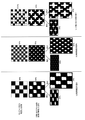
図14(a)〜(c)に、画像が伸びたり縮んだりすることによって画像の濃淡が変化する様子を示す。解像度の違いで、画像の伸縮による画像ムラの影響度が異なる。図14の(a)に解像度が低い場合、図14の(b)と(c)に解像度が高い場合の様子を示した。数値(%)は画像の濃度を表す。 14 (a) to 14 (c) show how the shade of the image changes as the image expands or contracts. Depending on the resolution, the degree of influence of image unevenness due to the expansion and contraction of the image differs. 14 (a) shows a state where the resolution is low, and FIGS. 14 (b) and 14 (c) show a state where the resolution is high. The numerical value (%) represents the density of the image.
まず、図14の(a)と(b)を比較する。イメージスキャナや、コンピュータ等の外部機器から50%のハーフトーン画像を出力しようとしても、図に示すように実際には飛び散り等が発生して濃い画像となる。図14(a)のように解像度の低い画像の場合は、マス目の大きさが図14の(b)の高解像度の場合よりも大きい。そのため、感光ドラム表面の周速と、記録材の移動速度と、が多少ずれたとしても白部が残り、画像濃淡の違いは目立たない。 First, (a) and (b) of FIG. 14 are compared. Even if an attempt is made to output a 50% halftone image from an image scanner or an external device such as a computer, as shown in the figure, scattering or the like actually occurs and the image becomes dark. In the case of an image having a low resolution as shown in FIG. 14 (a), the size of the grid is larger than that in the case of the high resolution of FIG. 14 (b). Therefore, even if the peripheral speed of the surface of the photosensitive drum and the moving speed of the recording material deviate slightly, the white part remains and the difference in image shading is not noticeable.
しかし、近年の細線や小さい文字を出力する需要に対応して、図14の(b)のように高解像度の画像を出力しようとする場合、マス目の大きさが図14の(a)の低解像度の場合よりも小さくなる。図15(a)〜(d)に示すように、画像の解像度や画像の倍率に拘らず、トナー画像の飛び散り具合(幅)は変わらない。そのため、高解像度印字で、転写時に画像が縮んだ場合、白部がトナーで埋まってしまい、濃度が濃く見える。 However, in response to the recent demand for outputting thin lines and small characters, when a high-resolution image is to be output as shown in FIG. 14 (b), the size of the squares is shown in FIG. 14 (a). It is smaller than the case of low resolution. As shown in FIGS. 15A to 15D, the degree of scattering (width) of the toner image does not change regardless of the image resolution and the image magnification. Therefore, in high-resolution printing, when the image shrinks during transfer, the white part is filled with toner and the density looks dark.
トナーの飛び散り等による、外部機器からの転送画像と、実際に記録材上に出力される画像の濃度誤差は、補正によりある程度解消できる。具体的には、あらかじめ、外部機器からの転送画像濃度に対する実際の出力画像濃度(通称、γカーブ)を測定しておく。そして外部機器から転送されてくる画像情報に対して補正をかける、という方法である。 The density error between the image transferred from the external device and the image actually output on the recording material due to toner scattering or the like can be eliminated to some extent by correction. Specifically, the actual output image density (commonly known as γ curve) with respect to the transfer image density from the external device is measured in advance. Then, the image information transferred from the external device is corrected.
そのため、外部機器から図14の(a)の場合と同じ画像情報が転送された場合、実際には図14の(c)のように補正される。具体的には、図14(a)のように画像濃度50%で低解像度の画像情報が転送されてきた場合、図14(c)のように解像度を高解像度に変換しつつ画像濃度を37.5%に下げる。このような補正により、実際に出力される画像の濃度を図14(a)の場合と同じく60%に合わせることができる。しかしながら、図14(c)の画像は高解像度なので、画像の伸びや縮みが生じると、画像濃度に与える影響が大きい。 Therefore, when the same image information as in the case of FIG. 14 (a) is transferred from the external device, the correction is actually performed as shown in FIG. 14 (c). Specifically, when low-resolution image information is transferred at an image density of 50% as shown in FIG. 14 (a), the image density is changed to 37 while converting the resolution to high resolution as shown in FIG. 14 (c). Reduce to 5.5%. By such correction, the density of the actually output image can be adjusted to 60% as in the case of FIG. 14A. However, since the image of FIG. 14C has a high resolution, if the image is stretched or shrunk, it has a great influence on the image density.
図14(a)の場合、伸縮がない画像の濃度が60%で、縮んだ画像の濃度が65%、伸びた画像の濃度が55%である。一方、図14(c)の場合、伸縮がない画像の濃度が60%で、縮んだ画像の濃度が75%、伸びた画像の濃度が45%である。図14(a)と図14(c)に示した伸縮のない画像は共に濃度60%であるにも拘らず、伸縮が生じると図14(c)の画像は図14(a)の画像よりも濃度が大きく変動することが判る。 In the case of FIG. 14A, the density of the non-stretched image is 60%, the density of the shrunk image is 65%, and the density of the stretched image is 55%. On the other hand, in the case of FIG. 14C, the density of the non-stretched image is 60%, the density of the shrunk image is 75%, and the density of the stretched image is 45%. Although the non-stretchable images shown in FIGS. 14 (a) and 14 (c) both have a density of 60%, when the stretch occurs, the image of FIG. 14 (c) is from the image of FIG. 14 (a). It can be seen that the concentration fluctuates greatly.
特許文献1の方法では、記録材を搬送する際の細かい速度変化に、感光ドラム表面に形成されるトナー画像の伸縮をぴったり合わせることができない。そのため、これまで以上に高解像度の画像を形成しようとすると、濃度ムラが生じてしまうことがあった。
In the method of
本発明の目的は、記録材へかかる外力が変化することによって生じる画像の伸縮を抑制することができ、濃度ムラのない画像の出力が可能な画像形成装置を提供することにある。 An object of the present invention is to provide an image forming apparatus capable of suppressing expansion and contraction of an image caused by a change in an external force applied to a recording material and outputting an image without uneven density.
上記の目的を達成するために、本発明に係る画像形成装置は、感光体と、前記感光体を画像情報に応じて露光し、前記感光体に潜像を形成する露光部と、前記潜像をトナーで現像する現像部と、記録材を収容するトレイと、前記トレイから記録材を給紙するフィードローラと、前記感光体から記録材へトナー画像を転写する転写部と、記録材を挟持搬送する定着ニップ部を形成する一対の回転体を有し、記録材に転写されたトナー画像を記録材に定着する定着部と、前記感光体の表面移動速度を制御する制御部と、を有し、記録材にトナー画像を形成する画像形成装置において、記録材が前記定着ニップ部に進入し前記定着ニップ部で搬送されることによって前記転写部における記録材の移動速度が上がる第1の所定のタイミング、よりも所定時間前のタイミングで、前記制御部は前記感光体の表面移動速度を下げ、記録材が前記定着ニップ部で搬送されている状態で記録材の後端が前記フィードローラによって形成されている圧接部を抜けることにより前記転写部における記録材の移動速度が上がる第2の所定のタイミング、よりも前記所定時間前のタイミングで、前記制御部は前記感光体の表面移動速度を更に下げることを特徴とする。 In order to achieve the above object, the image forming apparatus according to the present invention includes a photoconductor, an exposed unit that exposes the photoconductor in accordance with image information to form a latent image on the photoconductor, and the latent image. A developing unit for developing the image with toner, a tray for accommodating the recording material, a feed roller for feeding the recording material from the tray, a transfer unit for transferring the toner image from the photoconductor to the recording material, and a recording material. It has a pair of rotating bodies that form a fixing nip part to be conveyed, and has a fixing part that fixes the toner image transferred to the recording material to the recording material, and a control unit that controls the surface movement speed of the photoconductor. In the image forming apparatus for forming a toner image on the recording material, the recording material enters the fixing nip portion and is conveyed by the fixing nip portion, so that the moving speed of the recording material in the transfer portion is increased. The control unit reduces the surface movement speed of the photoconductor at a timing prior to the timing of The control unit determines the surface movement speed of the photoconductor at a second predetermined timing in which the movement speed of the recording material in the transfer portion increases by passing through the formed pressure contact portion, and at a timing prior to the predetermined time. It is characterized by further lowering.
本発明によれば、記録材へかかる外力が変化することによって生じる画像の伸縮を抑制することができ、濃度ムラのない画像の出力が可能な画像形成装置の提供を実現できる。 According to the present invention, it is possible to provide an image forming apparatus capable of suppressing expansion and contraction of an image caused by a change in an external force applied to a recording material and outputting an image without uneven density.
以下、本発明の実施形態について、図面を参照しながら説明する。本発明の好適な実施形態は、本発明における最良の実施形態の一例ではあるものの、本発明は以下の実施例により限定されるものではなく、本発明の思想の範囲内において種々の構成を他の構成に置き換えることは可能である。 Hereinafter, embodiments of the present invention will be described with reference to the drawings. Although a preferred embodiment of the present invention is an example of the best embodiment of the present invention, the present invention is not limited to the following examples, and various configurations are provided within the scope of the idea of the present invention. It is possible to replace it with the configuration of.
[実施例1]
(画像形成装置)
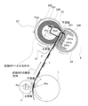
図1の(a)は電子写真記録技術を用いた画像形成装置(本実施例ではモノクロプリンタ)50の一例の概略構成を示す断面図である。(b)は露光部3の概略構成を示す平面図である。(c)はメインモータ22、及びスキャナモータ20の駆動系を示すブロック図である。
[Example 1]
(Image forming device)
FIG. 1A is a cross-sectional view showing a schematic configuration of an example of an image forming apparatus (monochrome printer in this embodiment) 50 using an electrophotographic recording technique. (B) is a plan view which shows the schematic structure of the
本実施例に示す画像形成装置の構成について、図1を参照しつつ説明する。(a)において破線は記録材Pの搬送経路(記録材Pパス)である。
感光ドラム(感光体)1は、画像形成装置50の駆動制御を司る制御装置(CPU)21によってメインモータ22(図1(c)参照)が駆動されることにより回転される。感光ドラム1の外径はΦ20mmである。通常のメインモータ22の駆動速度の時、感光ドラム1の外周面(表面)の移動速度(プロセス速度)Vdrumは200mm/secである。
The configuration of the image forming apparatus shown in this embodiment will be described with reference to FIG. In (a), the broken line is the transport path of the recording material P (recording material P path).
The photosensitive drum (photoreceptor) 1 is rotated by driving the main motor 22 (see FIG. 1C) by the control device (CPU) 21 that controls the drive of the
感光ドラム1表面は回転動作中に帯電ローラ(帯電部)2によって所定の極性・電位に一様に帯電処理される。
The surface of the
3はレーザースキャナ方式の露光部である。この露光部3は、不図示のイメージスキャナや、コンピュータ等の外部機器から入力する目的の画像情報に対応してオン/オフを変調したレーザー光Lを出力する。図1(b)に示すレーザー発振器52から出射されるレーザー光Lは、ポリゴンミラー51で反射され、fθレンズ53により屈折されて反射ミラー54を介して感光ドラム1へ至る。ポリゴンミラー51は、スキャナモータ20(図1(c)参照)により駆動される。ポリゴンミラー51で反射したレーザー光Lは、感光ドラム1を主走査方向(感光ドラム1の母線方向)に走査露光(照射)する。
スキャナモータ20の回転数とレーザー光Lの出力タイミングは、制御装置21によって、所定の解像度を得られるように制御される。本実施例では、主走査方向、及び副走査方向(感光ドラム1の周方向)の解像度は共に1200dpiとなるよう制御されている。
The rotation speed of the
露光部3による走査露光により感光ドラム1表面に目的の画像情報に対応した静電潜像が形成される。感光ドラム1表面の露光位置Peは、後述する転写ニップ(転写位置)Pbよりも感光ドラムの回転方向の上流側に位置している。感光ドラム1表面の周方向において、転写ニップPbの中心Pb1から露光位置Peまでの距離Dbeは31.4mm(図1(a)参照)である。
An electrostatic latent image corresponding to the target image information is formed on the surface of the
現像部4は、トナー容器4aに収納されているトナー(現像剤)を現像スリーブ4bを用いて感光ドラム1表面の潜像に付着させて潜像をトナー画像に現像する。
The developing
感光ドラム1と帯電ローラ2と現像部4はフレーム(不図示)に保持されてカートリッジ(以後、CRGと称する)として一体化されている。このCRGは画像形成装置本体50aに取り外し可能に装着されており、必要に応じて新品と交換することも可能である。
The
パッド方式の給紙部25のローラ12は、スタート信号に基づき回転する。このローラ12は分離パッド(分離部材)26と協同して、トレイ11に積載されている記録材Pの束から記録材を一枚ずつ分離して装置内に供給する。その記録材Pは入口ガイド28によって転写ニップPbに導入される。入口ガイド28は、記録材Pの転写ニップPbへの進入を補助するためのガイドである。転写ニップPbは、感光ドラム1と、感光ドラムに圧接させた転写ローラ(転写部)5と、によって形成されている。
The
給紙部25において、位置PaはバネSによってローラ12表面に加圧された分離パッド26とローラ12によって形成された圧接部を示している。圧接部Paの出口から転写ニップPbの中央Pb1までの距離は、高速化に対応するため、なるべく短い方がよい。本実施例では、圧接部Paの出口−転写ニップPbの中央Pb1間の距離(直線距離)Dabを40mmとしている(図1(a)参照)。
In the
転写ニップPbに記録材Pの先端が進入する時、感光ドラム1表面のトナー画像も転写ニップに到達する。転写ニップPbに進入した記録材Pは、転写ニップで挟持されつつ感光ドラム(表面の移動速度(周速)はVdrum)によって移動速度Vpaperで搬送される。その搬送過程において、転写ローラ5には不図示の転写バイアス印加電源から所定の転写電圧(転写バイアス)が印加される。転写ローラ5に転写バイアスが印加されることによって転写ニップPbで感光ドラム1表面からトナー画像が記録材P上に静電的に順次転写されていく。
When the tip of the recording material P enters the transfer nip Pb, the toner image on the surface of the
本実施例では、転写ローラ5として、直径5mmのニッケルメッキ鋼棒に、抵抗値を5×10⁷Ωに調整したNBR(ニトリル・ブタジエンゴムNitrile butadiene rubber)の発泡スポンジを覆設したローラを用いた。抵抗値はNBRにヒドリンhydrinやカーボン等の導電材を混入させることにより調整可能である。発泡スポンジの外径はΦ13mmである。発泡スポンジにおける記録材Pの搬送方向と直交する方向(長手方向)の幅は、装置に用いられる最大サイズの記録材としてレターサイズを想定して216mmとしてある。
In this embodiment, as the
転写ローラ5の感光ドラム1への圧接力が高いほど、転写ニップPbにおける記録材Pの移動速度Vpaperが感光ドラム1の表面移動速度Vdrumに倣いやすくなる。しかし、CRGを交換する際はユーザーが感光ドラム1を転写ローラ5に当接させなければならないため、圧接力が高すぎるとCRGの装置本体50aへの装着が困難となってしまう。そのため、圧接力は(4.9〜12.74N)(500〜1300gf)が好ましい。本実施例では、圧接力を9.8N(1000gf)とした。記録材Pの搬送方向において、転写ニップPbの幅は約1mmである。
The higher the pressure contact force of the
転写ニップPbでトナー画像の転写を受けた記録材Pは、感光ドラム1表面から分離され、未定着のトナー画像を記録材上に定着させるための定着部6へ向かって搬送される。未定着のトナー画像T(図3参照)を担持した記録材Pは入口ガイド27によって定着ニップPdに導入される。入口ガイド27は、記録材Pの定着ニップPdへの進入を補助するためのガイドである。
The recording material P to which the toner image has been transferred by the transfer nip Pb is separated from the surface of the
定着ニップPdは、加熱体としてのヒータ241(図3参照)を内包する筒状のフィルム24と、フィルムを介してヒータに加圧された加圧ローラ23と、よって形成されている。フィルム24はヒータ241によって加熱されている。そしてその記録材Pは定着ニップPdで加圧、加熱されながら挟持搬送され、これによってトナー画像は記録材上に加熱定着される。
The fixing nip Pd is formed by a
転写ニップPbから定着ニップPdまでの距離Dbdは、高速化のために短くするほうが良い。しかし、転写ニップPbから定着ニップPdまでの距離を短くしすぎると、定着部6の熱でCRGが昇温してCRGの構成部材の耐久性低下や、構成部材の電気的特性を変化させてしまい、上述の帯電、露光、現像、転写の各工程に支障を来す可能性がある。
The distance Dbd from the transfer nip Pb to the fixing nip Pd should be shortened for high speed. However, if the distance from the transfer nip Pb to the fixing nip Pd is too short, the heat of the fixing
本実施例では、転写ニップPb−定着ニップPd間の距離Dbdを、直線Laと、直線Lbと、を合計した距離(=50mm)としている。ここで、直線Laは、感光ドラム1の転写ニップPbの中央Pb1における接線と、定着入口ガイド27と交差する交点Pcと、を結んだ線である。直線Lbは、その交点Pcと、搬送方向における定着ニップPdの中央と、を結んだ線である。
In this embodiment, the distance Dbd between the transfer nip Pb and the fixing nip Pd is the total distance (= 50 mm) of the straight line La and the straight line Lb. Here, the straight line La is a line connecting the tangent line at the center Pb1 of the transfer nip Pb of the
先行する記録材Pと、その先行する記録材の次に供給される後続の記録材Pの間隔は、プロセス速度200mm/secでレターサイズ紙が1分間に35枚が出力されるように、45mm(時間にして0.9sec)としている。そのため、先行記録材Pの後端が転写ニップPbを抜ける一方で、感光ドラム1は直ちに後続記録材Pのための帯電、露光、現像、転写の各工程に備える。
The distance between the preceding recording material P and the subsequent recording material P supplied next to the preceding recording material is 45 mm so that 35 sheets of letter-sized paper are output per minute at a process speed of 200 mm / sec. (0.9 sec in time). Therefore, while the rear end of the preceding recording material P passes through the transfer nip Pb, the
定着部6を通った記録材Pはローラ14によって装置外に排出される。
The recording material P that has passed through the fixing
以上が画像形成装置50のプリント処理動作である。
The above is the print processing operation of the
次に、転写ニップPbにおける記録材Pの移動速度Vpaperに影響を与える外力について説明する。ここで、外力として、給紙部25の分離パッド(分離部材)26による摩擦抵抗と、定着部6の加圧ローラ23の熱膨張時の搬送力による引っ張り力がある。
Next, an external force that affects the moving speed Vpaper of the recording material P in the transfer nip Pb will be described. Here, as external forces, there are frictional resistance due to the separation pad (separation member) 26 of the
(分離パッド26による摩擦抵抗)
まず、給紙部25の構成について、図2を参照しつつ説明する。
(Friction resistance due to separation pad 26)
First, the configuration of the
給紙部25では、分離パッド26をローラ12表面に対向して配置している。そしてその分離パッド26をバネSによって加圧してローラ12表面に圧接している。
In the
分離パッド26の大きさは、記録材Pの搬送方向の幅が10mmであり、記録材Pの搬送方向と直交する長手方向の幅が40mmである。ローラ12の外径はΦ20mmである。ローラ12、及び分離パッド26の表面にはゴム等の摩擦性を有する材料を用いている。そのため、記録材Pをローラ12で供給する際、ローラによって複数枚の記録材Pが同時に供給されても2枚目以降の記録材は圧接部Paで分離パッド26との摩擦抵抗により搬送が阻止される。このために、ローラ12によって最上位の1枚の記録材Pのみを供給することができる。
The size of the
分離パッド26のローラ12に対する当接圧は、トレードオフの関係にある、記録材Pを供給できない状態と、記録材が重なって送り出される重送の状態と、のバランスを考慮すると、0.98〜4.9N(100〜500gf)が好ましい。本実施例では、当接圧を3.43N(350gf)とした。
The contact pressure of the
分離パッド26は、2枚目以降の記録材Pが1枚目の記録材につられて装置内へ供給されてしまうことを抑制するために、バネSによってローラ12に圧接されている。そのため、装置内へ供給されていく1枚目の記録材Pに分離パッド26によって直接摩擦抵抗を与える構成である。或いは、その1枚目の記録材Pに分離パッド26によって2枚目の記録材を介して間接的に摩擦抵抗を与える構成である。
The
転写ニップPbにおける記録材Pの移動速度Vpaperは、記録材が転写ニップPbで挟持搬送されるので、感光ドラム1の表面移動速度Vdrumと一致するはずである。しかし、転写ローラ5と感光ドラム1が記録材Pを挟持して搬送するときの摩擦抵抗は分離パッド26が記録材に与える摩擦抵抗よりも小さい。そのため、分離パッド26が記録材Pに与える摩擦抵抗が影響して、転写ニップPbにおける記録材の移動速度Vpaperが感光ドラム1の表面移動速度Vdrumよりも遅くなってしまう。
The moving speed Vpaper of the recording material P in the transfer nip Pb should match the surface moving speed Vdrum of the
この影響により、記録材上に転写されるトナー画像が縮んだ状態になってしまう。 Due to this effect, the toner image transferred onto the recording material becomes shrunk.
(加圧ローラ23の熱膨張時の搬送力による引っ張り力)
次に、定着部6の加圧ローラ23が熱膨張することによって、記録材Pが定着ニップPdに進入した瞬間に生じる引っ張り力について説明する。
(Pulling force due to the conveying force of the
Next, the tensile force generated at the moment when the recording material P enters the fixing nip Pd due to the thermal expansion of the
まず、定着部6の構成について、図3を参照しつつ説明する。
First, the configuration of the fixing
ヒータ241は、記録材Pの搬送方向の幅が6mm、記録材の搬送方向と直交する長手方向の幅が270mm、厚さが1mmの直方体状のアルミナ製の基板241aを有する。基板241aのフィルム24側の面に、通電により発熱するAg/Pd(銀パラジウム)等の抵抗発熱体241bを基板の長手方向に沿ってスクリーン印刷により塗工した。抵抗発熱体241bの厚さは10μmである。この抵抗発熱体241bは保護層241cとしてのガラスで覆われている。保護層241cの厚みは50μmである。
The
240は保持部材としてのヒータホルダーである。耐熱性樹脂の液晶ポリマー(LCP)からなるヒータホルダー240は、ヒータ241の熱を奪わないよう低熱容量であることが好ましい。ヒータ241はヒータホルダー240に設けられた溝に嵌め込まれて保持されている。
フィルム24は、フィルムが変形していない筒状の状態で外径がΦ18mmである。フィルム24は多層構成であり、フィルムの強度を保つための基層(不図示)と、その基層の表面に設けられた離型層(不図示)と、を有する。基層の材質は、耐熱性と耐摺動性を併せ持つポリイミド樹脂と、そのポリイミド樹脂に熱伝導率と強度を向上させるために添加されたカーボン系のフィラーと、からなる。離型層の材質は、フッ素樹脂の中でも離型性と耐熱性に優れるパーフルオロアルコキシ樹脂(PFA)である。
The
加圧ローラ23はフィルム24を挟んでヒータ241と対向して配置されている。ヒータホルダー240は、記録材Pの搬送方向と直交する長手方向の両端部を不図示の加圧機構によってフィルムの母線方向と直交する方向に加圧され、これによってフィルム24の内周面(内面)はヒータの保護層241cに圧接されている。
The
加圧ローラ23は、Φ11mmの鉄製の芯金230と、その芯金の表面に設けられたシリコーンゴムから成る厚さ3.5mmの弾性層232と、を有する。加圧ローラ23の外径は小さい方が熱容量を抑えられる。しかし、加圧ローラ23の外径が小さすぎると定着ニップPdの記録材Pの搬送方向の幅が狭くなってしまうので適度な径が必要である。本実施例では、加圧ローラ23の外径をΦ18mmとした。弾性層232の表面にはPFAからなる離型層231を設けている。
The
加圧ローラ23の表面硬度は低いほど小さい加圧力で定着ニップPdの幅を得ることができるが、表面硬度が低すぎると加圧ローラの耐久性が低下する。実施例では、加圧ローラ23の表面硬度をAsker−C硬度(4.9N(500g荷重))で40°とした。
The lower the surface hardness of the pressurizing
加圧ローラ23に対するヒータホルダー240の加圧力は強いほど定着ニップPdの幅が大きくなり定着性は良化するが、加圧ローラの弾性層232の変形量が大きくなり、弾性層232の耐久を短くしてしまう可能性がある。そのため加圧力は49N〜294N(5〜30kgf)程度が好ましい。本実施例では、加圧力を147N(15kgf)とした。この時の定着ニップPdの記録材Pの搬送方向の幅は7mmである。
The stronger the pressing force of the
加圧ローラ23はメインモータ22によって矢印方向へ回転される。フィルム24は加圧ローラ23の回転に追従してフィルム内面をヒータ241の保護層241cに摺動させながら矢印方向へ回転する。
The
加圧ローラ23の弾性層232にはフィルム24を介してヒータ241の熱が伝わり、これによって弾性層は熱膨張する。弾性層232が熱膨張すると、加圧ローラ23の外径は大きくなる(図3の23’参照)。そのため、弾性層232が熱膨張した加圧ローラ23による記録材Pの搬送速度は、弾性層が熱膨張する前の加圧ローラによる記録材の搬送速度よりも速くなる。
The heat of the
プリントを続けていくと加圧ローラ23の弾性層232に熱量が与えられるので、弾性層232の熱膨張量はさらに大きくなっていく。その弾性層232の熱膨張量に応じて、加圧ローラの表面移動速度も速くなる。熱膨張して表面移動速度が速くなった加圧ローラ23とフィルム24とで形成される定着ニップPdwの幅は、熱膨張する前の加圧ローラとフィルムとで形成される定着ニップPdの幅よりも広くなる。その幅広の定着ニップPdwに記録材Pが進入した瞬間にその記録材には加圧ローラ23の搬送力による引っ張り力が働くようになる。
As the printing is continued, the amount of heat is given to the
また、加圧ローラ23が熱膨張したときの定着ニップPdwの幅は熱膨張する前の転写ニップPbよりも広いため、その幅広の定着ニップで記録材Pへかかる加圧力は転写ニップよりも強い。そのため、加圧ローラ23が定着ニップPdwで記録材Pをグリップする力は転写ニップPbよりも強い。
Further, since the width of the fixing nip Pdw when the
そのため、転写ニップPbにおける記録材Pの移動速度Vpaperは、その記録材の先端が定着ニップPdwに進入した後は、加圧ローラ23の表面移動速度(周速)に支配されるようになる。つまり、記録材Pが定着ニップPdwに進入した瞬間からその記録材の移動速度Vpaperは感光ドラム1の表面移動速度Vdrumよりも速くなる。この場合、転写ニップPbにおける感光ドラム1表面の周速に対して記録材Pの移動速度Vpaperが速くなり、記録材上に転写されるトナー画像が伸びた状態になってしまう。
Therefore, the moving speed Vpaper of the recording material P in the transfer nip Pb becomes dominated by the surface moving speed (peripheral speed) of the
(回転駆動制御)
図1の(c)に示すように、本実施例に示す画像形成装置50の有するモータの数は、スキャナモータ20とメインモータ22の2つである。このモータ20、22は何れも制御装置(CPU)21によって回転駆動される。
(Rotation drive control)
As shown in FIG. 1 (c), the number of motors of the
ポリゴンミラーを回転させるスキャナモータ20は制御装置21によって一定速度を保つように制御される。
The
一方、メインモータ22の駆動速度は制御装置21によって変速可能である。メインモータ22の回転駆動力は、ローラ12、感光ドラム1、加圧ローラ23、及びローラ14にそれぞれ不図示の動力伝達機構を介して伝達される。つまり、感光ドラム1の表面移動速度Vdrumを減速するためにメインモータ22の駆動速度を減速させると、ローラ12、加圧ローラ23、ローラ14はメインモータ22と同じ比率で減速される。
On the other hand, the drive speed of the
転写ローラ5は、転写ニップPbに記録材Pが無い場合は感光ドラム1の回転に追従して回転する。そのため、転写ローラ5によって転写ニップPbにおける記録材Pの移動速度Vpaperが変化してしまうことを抑制できる。ところが、転写ニップPbに記録材Pが在る場合、転写ローラ5は感光ドラム1の回転によって搬送される記録材の移動速度Vpaperに追従して回転する。
When the transfer nip Pb does not have the recording material P, the
(メインモータ22の回転速度変更とそのタイミング)
前述したように、転写ニップPbにおける記録材Pの移動速度Vpaperは、記録材Pへかかる外力によって変化して、記録材上に転写されるトナー画像に伸び縮み、濃度ムラを発生させる。記録材Pへかかる外力によって発生するトナー画像の伸縮、及び濃度ムラを抑制するためには、感光ドラムの周速と記録材の移動速度を一致させる必要がある。
(Change in rotation speed of
As described above, the moving speed Vpaper of the recording material P in the transfer nip Pb changes due to the external force applied to the recording material P, and the toner image transferred onto the recording material expands and contracts, causing density unevenness. In order to suppress the expansion and contraction of the toner image and the uneven density generated by the external force applied to the recording material P, it is necessary to match the peripheral speed of the photosensitive drum with the moving speed of the recording material.
その方法を、記録材Pの搬送方向において10mm間隔の横線を記録材上に画く場合を例に説明する。 The method will be described by taking as an example a case where horizontal lines at intervals of 10 mm are drawn on the recording material in the transport direction of the recording material P.
例えば、記録材Pへかかる外力が記録材の搬送を阻害する方向の力であり、転写ニップPbにおける記録材の移動速度Vpaperが通常速度(プロセス速度200mm/sec)よりも常に2%遅い速度であったとする。この場合、感光ドラム1表面が10mm移動する間に、記録材Pは9.8mmしか移動しないので、記録材上に転写されるトナー画像は9.8mmとなり、本来の画像よりも縮んでしまう。
For example, the external force applied to the recording material P is a force in a direction that hinders the transport of the recording material, and the moving speed Vpaper of the recording material at the transfer nip Pb is always 2% slower than the normal speed (process speed 200 mm / sec). Suppose there was. In this case, since the recording material P moves only 9.8 mm while the surface of the
この現象に対して、転写ニップPbにおける感光ドラム1の表面移動速度Vdrumを2%速くする。すると、露光部3のポリゴンミラー51の走査露光間隔が一定であるので、感光ドラム1表面に形成される副走査方向の潜像間隔は10.2mm(通常速度の場合は10mm)となる。この潜像は現像部4によってトナー画像に現像されるので、感光ドラム1表面のトナー画像の間隔は10.2mmに伸びた状態となる。また、感光ドラム1の表面移動速度Vdrumを2%速くさせても、感光ドラムの表面移動速度Vdrumに対する記録材Pの相対速度は2%遅い状態である。
In response to this phenomenon, the surface moving speed Vdrum of the
メインモータ22の回転駆動速度を2%上げれば、ローラ12、加圧ローラ23、及びローラ14の速度も同じ比率で上がることになるため、転写ニップPbにおける記録材Pの移動速度Vpaperも2%速くなる。つまり、転写ニップPbにおける感光ドラム1の表面移動速度Vdrumと記録材Pの移動速度Vpaperの相関関係は変わらない。
If the rotational drive speed of the
転写ニップPbにおける記録材Pの移動速度Vpaperが変化することで、その記録材へ与える外力の大きさが変化する可能性はある。しかし、その外力の変化は小さいと考えられ十分無視できる。したがって、感光ドラム1表面に形成するトナー画像の間隔をあらかじめ10.2mmに伸ばしておくことで、転写ニップPbにおいて感光ドラム表面が10.2mm移動する間に、記録材Pはほぼ10mm移動する。そのため、記録材Pには目的の10mm間隔の横線を画くことが可能となる。
By changing the moving speed Vpaper of the recording material P in the transfer nip Pb, the magnitude of the external force applied to the recording material may change. However, the change in the external force is considered to be small and can be ignored. Therefore, by extending the distance between the toner images formed on the surface of the
ここで注意したいのは、転写ニップPbにおける感光ドラム1の表面移動速度Vdrumを変更するタイミングは、記録材Pへかかる外力が変化したタイミングと同じではないことである。感光ドラム1表面の副走査方向のトナー画像の画像間隔を変更するためには、感光ドラム表面に潜像を形成する時点で、その潜像の形成間隔を変更する必要がある。
It should be noted here that the timing of changing the surface moving speed Vdrum of the
図4に、感光ドラム1の表面移動速度Vdrumを変更するタイミングのイメージを示す。
FIG. 4 shows an image of the timing for changing the surface moving speed Vdrum of the
例えば、外力によって転写ニップPbにおける記録材Pの移動速度Vpaperが変化するタイミングが、記録材の先端から距離Ka離れた記録材位置PKaが転写ニップPbを移動している時である場合を考える(図4の(a)参照)。 For example, consider a case where the timing at which the moving speed Vpaper of the recording material P in the transfer nip Pb changes due to an external force is when the recording material position PKa at a distance Ka away from the tip of the recording material is moving the transfer nip Pb ( (See (a) in FIG. 4).
この場合、上記の記録材位置PKaと重なる感光ドラム表面の位置が、露光位置Peを通過するよりも前のタイミングで、あらかじめ、感光ドラムの表面移動速度Vdrumを変更しておく必要がある(図4の(b)参照)。ここで、感光ドラムの表面移動速度Vdrumの変更は、露光部3における感光ドラム1表面の露光開始時点を基準とする。即ち、感光ドラム1の表面移動速度Vdrumを変更するタイミングは、記録材Pへかかる外力が実際に変化するタイミングよりも、転写ニップPbの中心Pb1から露光位置Peまでの距離分前のタイミングである(図4の(c)参照)。
In this case, it is necessary to change the surface moving speed Vdrum of the photosensitive drum in advance at a timing before the position of the photosensitive drum surface overlapping the recording material position PKa passes through the exposure position Pe (Fig.). 4 (b)). Here, the change of the surface moving speed Vdrum of the photosensitive drum is based on the time when the exposure of the surface of the
(感光ドラム1の表面移動速度Vdrumの変更)
図5に、感光ドラム1の表面移動速度Vdrumの変化を表すタイミングチャートを示す。図5では、2枚のXerox Multi−purpose WhitePapers(LTRサイズ、75g)P1、P2に連続プリントする場合を示している。
図5に示すように、感光ドラム1の表面移動速度に対する記録材P1の相対移動速度は、図中v1’→v2’→v3’のように徐々に速くなっていく。
(Change of surface moving speed Vdrum of photosensitive drum 1)
FIG. 5 shows a timing chart showing a change in the surface moving speed Vdrum of the
As shown in FIG. 5, the relative moving speed of the recording material P1 with respect to the surface moving speed of the
プリンタがプリントレディー状態(RDY=ON)になり、プリント信号が入力(PRINT=ON)すると、給紙部25から記録材の給紙が始まる。上述したように、給紙後の記録材には、分離パッド26による摩擦抵抗が作用している。そのため、記録材P1が転写ニップPbに到達しても、感光ドラム1の表面移動速度に対する記録材P1の相対移動速度はマイナスである(v1’)。この状態は記録材P1の先端が定着ニップPdに到達するまで続く。
When the printer is in the print ready state (RDY = ON) and the print signal is input (PRINT = ON), the
なお、圧接ニップPaの出口と転写ニップPbの入口の距離は、距離Dab(40mm)−転写ニップPbの幅1mmの半分の長さ(0.5mm)=39.5mmである。転写ニップPbの入口と定着ニップPdの入口の距離は、距離Dbd(50mm)+転写ニップPbの幅1mmの半分の長さ(0.5mm)−定着ニップPdの幅7mmの半分の長さ(3.5mm)=47mmである。
The distance between the outlet of the pressure welding nip Pa and the inlet of the transfer nip Pb is a distance Dab (40 mm) − half the width of the transfer nip Pb of 1 mm (0.5 mm) = 39.5 mm. The distance between the inlet of the transfer nip Pb and the inlet of the fixing nip Pd is the distance Dbd (50 mm) + half the length of the transfer nip
タイミングt1’で記録材P1の先端が定着ニップPdに進入する。この時、記録材P1は圧接部Pa及び転写ニップPbにも挟まれている。また、加圧ローラ23は弾性層232の膨張によって周速がアップした状態であると仮定する。
At the timing t1', the tip of the recording material P1 enters the fixing nip Pd. At this time, the recording material P1 is also sandwiched between the pressure contact portion Pa and the transfer nip Pb. Further, it is assumed that the
記録材P1の先端が定着ニップPdに突入するタイミングt1’では、定着ニップにおける加圧ローラ23の表面移動速度と転写ニップPbにおける記録材P1の移動速度の相対速度差によって、加圧ローラが瞬間的に記録材に引っ張り力を与える。これによって転写ニップPbにおける感光ドラム1の表面移動速度に対する記録材P1の相対移動速度は、タイミングt1’から定常状態となるタイミングt2’まで徐々に速くなり、速度v1’から速度v2’へ変化する。
At the timing t1'when the tip of the recording material P1 rushes into the fixing nip Pd, the pressure roller momentarily moves due to the relative speed difference between the surface moving speed of the
タイミングt1’で加速し始めてからタイミングt2’で定常状態になるまでの時間は、記録材Pを挟持する部材の摩擦係数、及び記録材挟持力だけでなく、記録材の坪量と摩擦係数にも依存する。ここで、記録材Pを挟持する部材とは、分離パッド26とローラ12、感光ドラム1と転写ローラ5、加圧ローラ23とフィルム24を指す。本実施例では、上記時間はXerox Multi−purpose White Papers(LTRサイズ、75g)を用いた場合で0.3sec(距離にして60mm分)であった。
The time from the start of acceleration at timing t1'to the steady state at timing t2' depends not only on the friction coefficient of the member holding the recording material P and the holding force of the recording material, but also on the basis weight and friction coefficient of the recording material. Also depends. Here, the members that sandwich the recording material P refer to the
次に、記録材Pの後端が給紙部25を抜けて分離パッド26の摩擦抵抗がなくなるタイミングt3’では、記録材の搬送を阻害する方向の力が急に無くなるため、記録材には搬送方向に力が働いたようになる。即ち、ここでも記録材Pに引っ張り方向の力を与える。転写ニップPbにおける記録材Pの感光ドラム1の表面移動速度に対する相対移動速度は、t3’からタイミングt4’(記録材の後端が転写ニップPbを抜ける直前のタイミング)まで徐々に速くなり、速度v2’から速度v3’に変化する。
Next, at the timing t3'when the rear end of the recording material P passes through the
タイミングt3’で加速し始めてからタイミングt4’で定常状態になるまでの時間は0.1sec(距離にして20mm分)であった。ここで、タイミングt4’は記録材Pの後端が転写ニップPbを抜ける直前のタイミングである。 The time from the start of acceleration at timing t3'to the steady state at timing t4'was 0.1 sec (distance of 20 mm). Here, the timing t4'is the timing immediately before the rear end of the recording material P passes through the transfer nip Pb.
このように、記録材Pへかかる外力の変化によって感光ドラム1の表面移動速度に対する記録材の相対移動速度は変化する。
In this way, the relative moving speed of the recording material with respect to the surface moving speed of the
比較例の画像形成装置では、上記のタイミングt1’に対応するタイミングtk1でメインモータ22の駆動速度を変更している。同様に、上記のタイミングt2’、t3’、t4’にそれぞれ対応するタイミングtk2、tk3、tk4でメインモータ22の駆動速度を変更している。
In the image forming apparatus of the comparative example, the driving speed of the
比較例の画像形成装置は、記録材の先端が定着ニップに進入した以降から記録材の後端部にかけて感光ドラムの表面移動速度を連続的に減速させることにより、感光ドラム表面に形成されるトナー画像を副走査方向に徐々に縮ませている。元々、副走査方向に伸びる傾向にあった記録材上の画像に対して、感光ドラム表面に形成されるトナー画像を副走査方向に縮ませることにより、画像の伸び現象を抑制することができる。 The image forming apparatus of the comparative example is a toner formed on the surface of the photosensitive drum by continuously reducing the surface moving speed of the photosensitive drum from the time when the tip of the recording material enters the fixing nip to the rear end of the recording material. The image is gradually shrunk in the sub-scanning direction. By shrinking the toner image formed on the surface of the photosensitive drum in the sub-scanning direction with respect to the image on the recording material that originally tended to stretch in the sub-scanning direction, the stretching phenomenon of the image can be suppressed.
本実施例の画像形成装置50の特徴は以下の点にある。即ち、記録材Pへかかる外力が変化するタイミングt1’よりも、露光部3における感光ドラム1表面の露光位置Peから転写ニップPbの幅方向中心までの距離31.4mm分手前のタイミングt1で感光ドラムの表面移動速度を変更する。
The features of the
そのために、あらかじめ、タイミングt1’よりも距離31.4mm分手前のタイミングt1から、メインモータ22の駆動速度を変更しておく。こうすることで、記録材Pが加速し始めるタイミングt1’時点で記録材上に転写されるトナー画像の副走査方向の画像間隔(画像の大きさ)は、既に感光ドラム表面に静電潜像が形成される露光のタイミングで適切に縮められていることになる。
Therefore, the drive speed of the
同様に、記録材Pの移動速度が変化するタイミングt2’、t3’、t4’についても、それぞれ、距離31.4mm分手前のタイミングt2、t3、t4で、あらかじめ、感光ドラム1の表面移動速度を変更しておく。つまり、記録材Pの先端が転写ニップPbに進入したタイミング基準で記録材へかかる外力が変化するタイミングt1’〜t4’を、露光開始時のタイミング基準で考えたタイミングt1〜t4で、メインモータ22の駆動速度をそれぞれ変更すればよい。
Similarly, for the timings t2', t3', and t4'when the moving speed of the recording material P changes, the surface moving speed of the
タイミングt1’は、記録材Pの先端が定着ニップPdに進入するタイミングであり、記録材の先端が転写ニップPbの入口を通過してから47mm進んだタイミングである。メインモータ22の駆動速度を変更し始めるタイミングt1は、タイミングt1’よりも31.4mm前のタイミングであり、露光開始から0.235sec後である。
The timing t1'is the timing at which the tip of the recording material P enters the fixing nip Pd, and is the timing at which the tip of the recording material advances 47 mm after passing through the inlet of the transfer nip Pb. The timing t1 at which the drive speed of the
記録材移動速度が定常状態になるタイミングt2’は、上述したようにタイミングt1’から0.3sec(距離にして60mm)後のタイミングである。メインモータ22の駆動速度を定常状態にし始めるタイミングt2は、タイミングt2’よりも31.4mm手前のタイミングであり、露光開始から0.535秒後である。
The timing t2'when the recording material moving speed becomes a steady state is the timing 0.3 sec (60 mm in distance) from the timing t1'as described above. The timing t2 at which the drive speed of the
タイミングt3’は、記録材Pの後端が給紙部25を抜けるタイミングであり、記録材の後端が転写ニップPbの出口に到達するまでの距離が39.5mmとなるタイミングである。記録材Pとして、記録材の搬送方向の長さ279mmであるLTRサイズ紙を用いた場合は、そのLTRサイズ紙の先端が転写ニップPbの入口を通過してから239.5mm進んだタイミングである。タイミングt3はタイミングt3’よりも31.4mm手前のタイミングであり、露光開始から1.193sec後である。
The timing t3'is the timing at which the rear end of the recording material P passes through the
記録材移動速度が定常状態になるタイミングt4’は、上述したようにタイミングt3’から0.1sec(距離にして20mm)後のタイミングである。メインモータ22の駆動速度を定常状態にし始めるタイミングt4は、タイミングt4’よりも31.4mm手前のタイミングであり、露光開始から1.243sec後である。
The timing t4'when the recording material moving speed becomes a steady state is the timing 0.1 sec (20 mm in distance) after the timing t3' as described above. The timing t4 at which the drive speed of the
因みに、連続プリントの2枚目のプリントに備えて、1枚目分の露光工程が終了したタイミング(記録材P1の後端が転写ニップPbを抜けるタイミングの転写ニップ−露光位置間距離分手前のタイミング)で、感光ドラムの表面移動速度を通常の速度(200mm/sec)に戻してよい。 By the way, in preparation for the second printing of the continuous printing, the distance between the transfer nip and the exposure position before the timing when the exposure process for the first sheet is completed (the timing when the rear end of the recording material P1 passes through the transfer nip Pb). At the timing), the surface moving speed of the photosensitive drum may be returned to the normal speed (200 mm / sec).
露光部3によって先行する記録材P1の後端分の潜像形成が終わってから後続の記録材P2の先端分の潜像形成を開始するまでの間隔は45mmある。その間隔45mmの間に、感光ドラム1の表面移動速度を通常の速度に戻しておくことで、再び図中Cにて示すタイミングから帯電、露光、現像、転写の各工程を繰り返すことが可能となる。
There is an interval of 45 mm from the completion of the latent image formation of the rear end of the preceding recording material P1 by the
(本実施例の効果)
比較例の画像形成装置では、転写ニップPbにおける感光ドラムの表面移動速度を、記録材へかかる外力が変化するタイミングt1’で変更していた。
(Effect of this example)
In the image forming apparatus of the comparative example, the surface moving speed of the photosensitive drum in the transfer nip Pb was changed at the timing t1'when the external force applied to the recording material changed.
比較例のように、記録材へかかる外力が変化して、転写ニップPbにおける記録材の移動速度が変化するタイミングt1’時点で感光ドラム1の表面移動速度を減速させたとする。この場合、既に感光ドラム表面の露光位置−転写ニップ間の距離31.4mmの領域に既に形成されているトナー画像の倍率を変更することができない。
As in the comparative example, it is assumed that the surface moving speed of the
従って、比較例の制御方法では、感光ドラム表面の移動速度と記録材の移動速度が合わない期間が存在する。そしてその期間に対応する領域で記録材上の画像の濃淡が変化してしまう。 Therefore, in the control method of the comparative example, there is a period in which the moving speed of the surface of the photosensitive drum and the moving speed of the recording material do not match. Then, the shading of the image on the recording material changes in the region corresponding to that period.
本実施例と比較例の画像形成装置における感光ドラムの表面移動速度の制御方法について、以下に説明する。比較する基準は、レターサイズの用紙全面に50%のハーフトーン画像を600dpi、1200dpiで出力したときの画像濃淡と、画像濃淡ムラの違いである。表1に、画像濃淡の比較結果を示す。濃淡の変化がほとんどない場合を○、濃淡の変化が目立つ場合を×とする。 The method of controlling the surface moving speed of the photosensitive drum in the image forming apparatus of this example and the comparative example will be described below. The standard for comparison is the difference between the image shading when a 50% halftone image is output at 600 dpi and 1200 dpi on the entire surface of the letter-sized paper and the image shading unevenness. Table 1 shows the comparison results of image shading. The case where there is almost no change in shade is marked with ◯, and the case where the change in shade is noticeable is marked with ×.

図6に、画像濃淡ムラの比較結果を示す。600dpiの解像度では、目立たなかった画像濃淡ムラも、1200dpiでは濃淡差が大きくなる。そのため、感光ドラムの周速と記録材の移動速度が合わない領域において画像濃淡ムラが目立つようになる。 FIG. 6 shows a comparison result of image shading unevenness. At a resolution of 600 dpi, the unevenness of image shading that was not noticeable becomes large at 1200 dpi. Therefore, unevenness in image shading becomes conspicuous in a region where the peripheral speed of the photosensitive drum and the moving speed of the recording material do not match.
本実施例の方法によれば、記録材P全域で、画像倍率の変動を抑えることが可能となる。そのため、高解像度の画像であっても、画像濃淡ムラをほとんど無くすことができる。 According to the method of this embodiment, it is possible to suppress fluctuations in the image magnification over the entire recording material P. Therefore, even if the image has a high resolution, unevenness in image shading can be almost eliminated.
本実施例の画像形成装置50は、記録材Pへかかる外力の変化に先んじて、感光ドラムの表面移動速度を変更する。感光ドラム1の表面移動速度を変更するタイミングは、外力が変化するタイミングt1’〜t4’よりも、露光位置−転写ニップ間の距離分手前のタイミングt1〜t4である。
The
つまり、記録材へかかる外力が変化して転写ニップにおける記録材の移動速度が変化し始めるt1’〜t4’よりも手前のt1〜t4から、感光ドラムの表面移動速度を変更する。 That is, the surface moving speed of the photosensitive drum is changed from t1 to t4 before t1'to t4', where the external force applied to the recording material changes and the moving speed of the recording material at the transfer nip begins to change.
これにより、記録材Pへかかる外力が変化することによって生じる画像伸縮を抑制することができ、濃度ムラのない画像を出力することができる。 As a result, it is possible to suppress image expansion and contraction caused by changes in the external force applied to the recording material P, and it is possible to output an image without uneven density.
感光ドラム1の表面移動速度を変更するタイミングは、露光位置−転写ニップ間の距離分手前のタイミングに限らない。例えば、記録材Pは、記録材の種類、及び画像形成装置の構成によっては、装置本体内で湾曲する場合がある。特開2000−181262号公報のように、定着部6による記録材Pのシワや画像乱れの発生を抑制するために、入口ガイド27の記録材Pの搬送経路への侵入量を大きくして、その搬送経路を定着部6のフィルム24側に歪ませるような構成がある。このような構成においては、記録材Pのコシにより、記録材が湾曲しやすい。
The timing for changing the surface movement speed of the
このように、入口ガイド27の記録材Pの搬送経路への侵入量が大きいことによって、転写ニップPbから定着部6までの搬送経路内で記録材に湾曲が生じていた場合を想定する。
As described above, it is assumed that the recording material is curved in the transport path from the transfer nip Pb to the fixing
この場合、記録材の先端が定着ニップPdに進入しても、加圧ローラ23の記録材を引っ張る力は、すぐには転写ニップの記録材の移動速度に変化を与えない。湾曲が解消した後に初めて、転写ニップPbにおける記録材Pの移動速度が加速する。つまり、記録材Pの先端が定着ニップPdに進入すると想定されるタイミング(図5中t1’)よりも、少し遅いタイミングで転写ニップPbにおける記録材の移動速度が変化することになる。
In this case, even if the tip of the recording material enters the fixing nip Pd, the force pulling the recording material of the
このような場合においては、タイミングt1よりも少し遅いタイミングで、感光ドラム1の表面移動速度を変更し始めても良い。
In such a case, the surface moving speed of the
このように、感光ドラム1の表面移動速度を変更するタイミングは、画像形成装置の構成や記録材の種類によって適切に変更して良い。そのタイミングは、タイミングt1付近のタイミングであって、実際に記録材Pへの外力が変化するタイミングt1’よりも手前のタイミングであれば良い。これによって、転写ニップPbにおける感光ドラム1の表面移動速度と記録材Pの移動速度のズレによる画像伸縮を抑制することが可能となる。
As described above, the timing of changing the surface moving speed of the
[実施例2]
画像形成装置50の他の例を説明する。本実施例に示す画像形成装置50の特徴は、記録材Pの表裏を反転する反転機構(反転部)17を用いて記録材の両面印字が可能である点、及び感光ドラム1の表面移動速度の変化が記録材の1面目と2面目で異なることにある。
[Example 2]
Another example of the
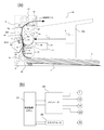
以下、本実施例の画像形成装置50の構成について、図7を参照しつつ説明する。図7の(a)は本実施例の画像形成装置50の概略構成を示す断面図である。(b)はメインモータ22、及びスキャナモータ20の駆動系を示すブロック図である。
本実施例においては、実施例1と同じ部材には同一符号を付して、その部材の説明を省略する。
Hereinafter, the configuration of the
In this embodiment, the same members as those in the first embodiment are designated by the same reference numerals, and the description of the members will be omitted.
反転機構17は、定着部6とローラ14との間に設けられた導入ガイド18と、この導入ガイドからの記録材Pを反転するための搬送路Uを形成する搬送ガイド16と、この搬送ガイド16の搬送路内で記録材を挟持搬送するローラ19と、を有する。
The reversing
記録材Pに両面印字する場合には、1面目の印字が終了して記録材Pの後端が導入ガイド18の先端Qを通過した後、ローラ14が逆転し、記録材Pを搬送ガイド16の搬送路Uに沿ってローラ19に案内する。
In the case of double-sided printing on the recording material P, after the printing on the first surface is completed and the rear end of the recording material P passes the tip Q of the
ローラ19はメインモータ22の駆動によって回転される。ローラ19の表面移動速度は感光ドラム1の表面移動速度と同じになるように設定されている。ローラ19によって挟持搬送される記録材Pは、トナー画像を記録材の2面目(1面目の非印字面側)に転写するために、搬送ガイド16の搬送路Uに設けられた略U字形状の反転路U1を通る。そしてその記録材Pは、2面目を感光ドラム1側にして、再び入口ガイド28によって転写ニップPbに導入される。
The
その記録材Pは転写ニップPbで挟持搬送され、その搬送過程で転写ローラ5に所定の転写電圧が印加されることによって感光ドラム1表面のトナー画像が2面目に転写される。
The recording material P is sandwiched and conveyed by the transfer nip Pb, and the toner image on the surface of the
2面目に未定着のトナー画像Tを担持した記録材Pは入口ガイド27によって定着部6の定着ニップPdに導入される。その記録材Pは定着ニップPdで挟持搬送され、これによって記録材の2面目のトナー画像は記録材上に加熱定着される。
The recording material P carrying the unfixed toner image T on the second surface is introduced into the fixing nip Pd of the fixing
定着部6を出た記録材Pはローラ14によって装置外部に排出される。
The recording material P that has exited the fixing
このように、記録材Pに両面印字する場合、記録材の1面目プリント時と2面目プリント時では搬送経路が異なる。そして、転写ニップPbにおける記録材Pの移動速度に影響を与える外力も1面目プリント時と2面目プリント時で異なる。 In this way, when double-sided printing is performed on the recording material P, the transport path is different between the first side printing and the second side printing of the recording material. The external force that affects the moving speed of the recording material P in the transfer nip Pb is also different between the first side printing and the second side printing.
記録材Pの2面目プリント時は記録材が給紙部25を通らないため、記録材は分離パッド26による摩擦抵抗を受けない。そのため、1面目プリント時では、転写ニップPbにおける記録材Pの移動速度は記録材の先端が定着ニップPdに進入するまで、感光ドラム1の表面移動速度よりも遅かった。しかしながら、2面目プリント時は、記録材の先端が定着ニップPdに進入するまで、感光ドラム1の表面移動速度と記録材Pの移動速度は一致する。
When printing on the second surface of the recording material P, the recording material does not pass through the
また、1面目プリント時では、記録材Pの先端が加圧ローラ23に進入した後も、しばらくの間、記録材に給紙部25による力が作用していた。しかしながら、2面目プリント時には、記録材にその力は作用しない。さらに、2面目プリント時は、1面目プリント時に記録材にかかっていた分離パッド26による摩擦抵抗がないため。そのため、2面目プリント時、記録材先端が定着ニップに進入した時点における転写ニップPbにおける記録材Pの移動速度は、1面目プリント時よりも速くなる。
Further, at the time of printing on the first surface, even after the tip of the recording material P entered the
したがって、1面目プリントと2面目プリント時では感光ドラム1の表面移動速度を変更する必要がある。
Therefore, it is necessary to change the surface moving speed of the
図8に、本実施例の画像形成装置50について、感光ドラム1の表面移動速度Vdrumの変化を表すタイミングチャートを示す。図8では、Xerox Multi−purpose White Papers(LTRサイズ、75g)を両面プリントする場合を示している。
FIG. 8 shows a timing chart showing a change in the surface moving speed Vdrum of the
感光ドラム1の表面移動速度に対する記録材Pの相対移動速度は、図8に示す通りであり、1面目プリント時と2面目プリント時に記録材にかかる外力の違いにより異なる。転写ニップPbにおける、1面目プリント時の記録材Pの相対移動速度の変化と、感光ドラム1の表面移動速度の変化は実施例1と同じである。2面目プリント時に関しては、記録材Pの相対移動速度が変化するのはタイミングt5’と定常速度になるタイミングt6’である。本実施例において、タイミングt6’は、タイミングt5’から0.2sec後(距離にして40mm分)であった。
The relative moving speed of the recording material P with respect to the surface moving speed of the
1面目プリント中の記録材が転写ニップPbを抜けて、その記録材が表裏反転されて再び転写ニップに進入するまでの間の間隔(1面目−2面目間隔)は100mmである。 The interval (interval between the first surface and the second surface) between the recording material being printed on the first surface passing through the transfer nip Pb, the recording material being turned upside down and entering the transfer nip again is 100 mm.
感光ドラムの表面移動速度を変更するべきタイミングは、記録材の相対移動速度が変化するt5’、t6’よりも、感光ドラム表面の露光位置−転写ニップ間の距離31.4mm手前のt5、t6である。このように、1面目プリント時と2面目プリント時では、感光ドラム1の表面移動速度を変更するタイミングを変える。
The timing at which the surface movement speed of the photosensitive drum should be changed is t5, t6, which is 31.4 mm before the distance between the exposure position on the surface of the photosensitive drum and the transfer nip, rather than t5'and t6', where the relative movement speed of the recording material changes. Is. In this way, the timing for changing the surface movement speed of the
また、前述の通り、2面目プリント時、記録材は給紙部25を通らないため、分離パッド26による摩擦抵抗を受けない。そのため、1面目プリント時と2面目プリント時では、露光開始タイミングにおける感光ドラム1の表面移動速度も異なる。
Further, as described above, at the time of printing on the second surface, since the recording material does not pass through the
1面目プリント時では、転写ニップPbにおける記録材Pの移動速度は、記録材が加圧ローラ23に進入するまで、感光ドラム1の表面移動速度よりも遅かった。しかしながら、2面目プリント時は、記録材が加圧ローラ23に進入するまで、感光ドラムの表面移動速度と記録材の移動速度は一致する。本例の装置は、このような記録材Pの1面目プリント時と2面目プリント時の移動速度の変化に対応させることができる。
At the time of printing on the first surface, the moving speed of the recording material P in the transfer nip Pb was slower than the surface moving speed of the
さらに、1面目プリント時では、記録材が加圧ローラ23に進入した後も、しばらくの間、記録材に給紙部25による力が作用していた。しかしながら、2面目プリント時には、記録材にその力は作用しない。この外力の有無によって、タイミングt1´とタイミングt2´間の相対速度変化の傾きと、タイミングt5´とタイミングt6´間の相対速度変化の傾きが異なる。つまり、感光ドラムの表面移動速度に対する記録材の相対移動速度の変化が1面目プリント時と2面目プリント時で異なる。
Further, at the time of printing on the first surface, even after the recording material entered the
そこで、タイミングt1からt2への加速度と、タイミングt5からt6への加速度を変えている。 Therefore, the acceleration from timing t1 to t2 and the acceleration from timing t5 to t6 are changed.
本実施例のように両面プリントを行う場合でも、感光ドラムの表面移動速度を、実際に外力が変化するタイミングよりも手前のタイミングで、外力の大きさに応じて適切に変更すれば、実施例1と同様の効果を得ることができる。 Even in the case of double-sided printing as in this embodiment, if the surface moving speed of the photosensitive drum is appropriately changed according to the magnitude of the external force at a timing before the timing when the external force actually changes, the embodiment The same effect as in 1 can be obtained.
[実施例3]
画像形成装置50の他の例を説明する。装置本体50a内で記録材Pへかかる外力は、実施例1及び実施例2で示した、給紙部25の分離パッド26による摩擦抵抗や、加圧ローラ23の引っ張り力に限られない。実施例1の画像形成装置50では、記録材Pの先端が定着ニップPdに進入した後、外力として記録材Pを引っ張る方向に記録材に力を与えている例であった。このため、感光ドラム1の表面移動速度を徐々に減速させる装置を示した。本実施例においては、感光ドラム1の表面移動速度を加速させる例を挙げる。
[Example 3]
Another example of the
図9(a)に示す装置は、転写ニップPbへの入口ガイド281を感光ドラム1側に侵入させた構成である。この構成により、記録材に転写されるトナー画像の乱れを抑制できる。この構成の場合、記録材Pと入口ガイド281の摺擦が大きくなる。つまり、記録材Pの転写ニップPbへの進入を補助するための入口ガイド281は、記録材が入口ガイドに接触している間、その記録材に摺動抵抗を与える。
The device shown in FIG. 9A has a configuration in which the
この装置は更に、感光ドラム1表面から分離した後の記録材を定着部6に向かうよう記録材の搬送方向を規制するフレーム282を有する。このフレーム282も、記録材に摺動抵抗を与える。
This device further includes a
これらの摺擦抵抗がバックテンションとなって、転写ニップPbにおける記録材Pの移動速度Vpaperが低下してしまう。 These rubbing resistances serve as back tension, and the moving speed Vpaper of the recording material P in the transfer nip Pb decreases.
本実施例の画像形成装置50の構成について、図9を参照しつつ説明する。図9の(a)は本実施例の画像形成装置50の概略構成を示す断面図である。(b)はメインモータ22、及びスキャナモータ20の駆動系を示すブロック図である。
The configuration of the
本実施例においても、実施例1と同じ部材に同一の符号を付して、その部材の説明を省略する。 Also in this embodiment, the same members as those in the first embodiment are designated by the same reference numerals, and the description of the members will be omitted.
入口ガイド281は、給紙部25の圧接部Paと、転写ニップPbの上流端(図3参照)と、を結ぶ直線Bに対して感光ドラム1側に大きく侵入している。
The
この入口ガイド281の侵入量bは、大きいほど転写によるトナー画像乱れが良化する。しかし、侵入量bが大きすぎると、入口ガイド281と感光ドラム1表面との間の間口cが狭くなって記録材Pが転写ニップPbへ安定して搬送されにくくなる。本実施例では、侵入量bを1.6mmとし、間口cを2mmとした。
The larger the penetration amount b of the
また、入口ガイド281の感光ドラム1表面側の頂点と、転写ニップの中心Pb1と、を結んだ直線C上の長さが5mmとなるように、入口ガイド281が設けられている。
Further, the
転写ニップPbと入口ガイド27との間には、記録材Pを定着部6に向かうように記録材の搬送経路を規制する必要があるため、フレーム282を設けている。転写ニップPbを抜けた記録材Pは、直線Cに沿って直進して、その直線とフレーム282との交点Pfでフレーム282にぶつかり、それ以降、フレームに摺動しながら定着部6へ向かう。
A
記録材Pの搬送方向において、転写ニップPbの中心Pb1から交点Pfまでの距離は10mmである。また、交点Pfから入口ガイド27の頂点Pgまでの距離と、その頂点から定着ニップPdの中心Pd1までの距離と、の合計が40mmである。
In the transport direction of the recording material P, the distance from the center Pb1 of the transfer nip Pb to the intersection Pf is 10 mm. Further, the total of the distance from the intersection Pf to the apex Pg of the
図10に、本実施例の画像形成装置50について、感光ドラム1の表面移動速度Vdrumを変更するタイミングチャートを示す。図10では、2枚のXerox Multi−purpose WhitePapers(LTRサイズ、75g)に連続プリントする場合を示している。
FIG. 10 shows a timing chart for changing the surface moving speed Vdrum of the
感光ドラム1の表面移動速度Vdrumに対する記録材Pの相対移動速度は、記録材が分離パッド26及び入口ガイド281から摩擦抵抗を受けるため、感光ドラムの表面移動速度よりも遅い。そのため、記録材Pは感光ドラム1の表面移動速度よりも遅い速度で転写ニップPbに進入する。
The surface moving speed of the
その後、記録材Pは、転写ニップPbの記録材の搬送方向の下流端(図3参照)から9.5mmの直線距離にあるフレーム282上の交点Pfに向かい、その記録材の先端がフレーム上の交点Pfにぶつかったタイミングt7’からフレーム282の摩擦抵抗を受け始める。そのため、タイミングt7’以降、記録材Pの移動速度は徐々に減速を始める。
After that, the recording material P is directed toward the intersection Pf on the
転写ニップPbから定着ニップPdまでの距離は47mmである。この距離は、転写ニップPbの記録材Pの搬送方向の下流端と交点Pfを結ぶ直線と、その交点と入口ガイド27の頂点Pgを結ぶ直線と、その頂点と定着ニップPdの記録材の搬送方向の上流端(図3参照)を結ぶ直線と、を合計した距離である。転写ニップPb−定着ニップPd間の距離が47mmと短いため、タイミングt7’で減速し始めてから定常状態になる前に、記録材Pの先端は定着ニップPdに進入し(タイミングt8’)、加圧ローラ23によって搬送されるようになる。
The distance from the transfer nip Pb to the fixing nip Pd is 47 mm. This distance is determined by the straight line connecting the downstream end of the recording material P of the transfer nip Pb in the transport direction and the intersection Pf, the straight line connecting the intersection and the apex Pg of the
表面移動速度が感光ドラム1の表面移動速度よりも速い加圧ローラ23によって記録材Pが搬送されるようになった後、フレーム282に沿って湾曲していた記録材Pは、その湾曲が徐々に解消されて、フレームから離れる。記録材Pの相対移動速度は、この湾曲が解消されたのち、加圧ローラ23の搬送力による引っ張り力によって加速される。本実施例において、湾曲が解消されたタイミングt8’’は、実際に記録材Pの先端が加圧ローラ23に進入したタイミングt8’より0.075sec後(距離にして15mm分)のタイミングであった。
After the recording material P is conveyed by the
タイミングt8’’を過ぎてから、加圧ローラ23の表面移動速度が支配的である定常状態で記録材Pが搬送されるようになるタイミングt9’は、0.2sec後(距離にして40mm分)であった。
After the timing t8'' is passed, the timing t9'when the recording material P is conveyed in a steady state in which the surface movement speed of the pressurizing
その後、記録材Pの相対移動速度は、入口ガイド281の摺動抵抗が無くなるタイミングt10’と、分離パッド26の摩擦抵抗が無くなるタイミングt11’で、徐々に加速し、タイミングt12’で定常状態となった。
Thereafter, the relative movement speed of the recording material P, 'and the friction resistance is eliminated timing t11 of the separation pad 26' timing t10 sliding resistance of the
このように、記録材Pへかかる外力がタイミングt7’〜t12’で変わっていくことに応じて、記録材の相対移動速度は変化していく。本実施例では、この記録材Pの相対移動速度の変化に先んじて、感光ドラム1の表面移動速度を変化させる。
In this way, the relative moving speed of the recording material changes as the external force applied to the recording material P changes at the timings t7'to t12'. In this embodiment, the surface moving speed of the
そこで、記録材Pの相対移動速度が変化するタイミングよりも、感光ドラム1表面の露光位置−転写ニップ間の距離31.4mm分手前のタイミングで、あらかじめ、感光ドラム1の表面移動速度を変更しておく。ここで、記録材Pの相対移動速度が変化するタイミングはt7’、t8’’、t9’、t10’、t11’、t12’であり、感光ドラム1表面の露光位置−転写ニップ間の距離31.4mm分手前のタイミングはt7、t8、t9、t10、t11、t12である。
Therefore, the surface moving speed of the
実際に記録材Pへ与える外力が変わるのはタイミングt8’であるが、ループが解消して記録材の相対移動速度が変わるのはタイミングt8’’であるので、タイミングt8はタイミングt8’’より31.4mm分前で変更するのが良い。タイミングt8’に対しては、(t8’−t8)=0.082sec(距離にして16.4mm分)手前のタイミングである。 The external force actually applied to the recording material P changes at timing t8', but the loop is resolved and the relative moving speed of the recording material changes at timing t8'', so timing t8 is from timing t8''. It is better to change it 31.4 mm before. With respect to the timing t8', the timing is before (t8'-t8) = 0.082 sec (16.4 mm in distance).
このように、実際に記録材Pへ与える外力が変化するタイミングよりも31.4mm分手前のタイミングで感光ドラム1の表面移動速度を外力の大きさに応じて適切に変更すれば、実施例1と同様の効果を得ることができる。
In this way, if the surface moving speed of the
[実施例4]
画像形成装置50の他の例を説明する。本実施例の画像形成装置50は、露光部3としてLEDプリントヘッド方式の装置を用いている。
[Example 4]
Another example of the
露光部3はレーザースキャナ方式に限らない。特開2012−101497号公報のように、露光部3としてLED(発光ダイオード)光源を配置するLEDプリントヘッド方式の装置を用いてよい。この場合、一定速度で回転する感光ドラム1に対してLED光源の発光タイミングを変更することにより、実施例1と同様の効果を得ることも可能である。LEDプリントヘッド方式の露光部3は、レーザースキャナ方式に比べてポリゴンミラーを回転するためのスキャナモータや、レーザー光を走査するためのポリゴンミラー等の機構を無くすことができるため、画像形成装置50の小型化が可能となる。
The
本実施例の画像形成装置50の特徴は、感光ドラム1の表面移動速度を一定速度として、LEDプリントヘッド方式である露光部3の発光間隔を、従来よりも手前のタイミングで変更することにある。露光部3において、発光間隔を変更するタイミングとは、記録材Pへかかる外力が変化するタイミングよりも、感光ドラム1表面の露光位置Peから転写ニップPbの中心Pb1までの距離(=31.4mm)分だけ手前のタイミングである必要がある。
The feature of the
本実施例の画像形成装置50の構成について、図11を参照しつつ説明する。図11の(a)は本実施例の画像形成装置50の概略構成を示す断面図である。(b)は露光部3の発光源72を示す正面図である。(c)は信号発生回路74と、メインモータ22の駆動系を示すブロック図である。
The configuration of the
本実施例においても、実施例1と同じ部材に同一符号を付して、その部材の説明を省略する。 Also in this embodiment, the same members as those in the first embodiment are designated by the same reference numerals, and the description of the members will be omitted.
露光部3は、発光素子(LED)71を備える発光源72と、発光源から出射された光Laを感光ドラム1表面に結像するレンズ(光学手段)を複数備えるプリントヘッド73と、を有する。この露光部3は信号発生回路74によって制御される。信号発生回路74は、不図示のイメージスキャナや、コンピュータ等の外部機器から入力される目的の画像情報に基づき、画像データの並び替えや光量の補正等の処理を行う。解像度は、主走査方向、及び副走査方向共に1200dpiとなるよう制御される。信号発生回路74は制御装置21によって制御される。
The
本実施例の画像形成装置50のように、露光部3がLEDプリントヘッド方式である場合、信号発生回路74で発光源72の発光間隔を変更することによって、感光ドラム1表面の副走査方向の潜像間隔を変更することができる。例えば、感光ドラム1の表面移動速度Vdrumを一定にした状態で、発光間隔を長くすると、感光ドラム表面の副走査方向に形成される潜像は、通常よりも伸びた状態となる。
When the
記録材Pの搬送方向10mm間隔の横線を記録材上に画く時、記録材へかかる外力が記録材の搬送を阻害する方向の力である場合を例に説明する。 When drawing horizontal lines at intervals of 10 mm in the transport direction of the recording material P on the recording material, a case where the external force applied to the recording material is a force in a direction that hinders the transport of the recording material will be described as an example.
転写ニップPbにおける記録材Pの移動速度Vpaperが通常速度(プロセス速度200mm/sec)よりも2%遅かった場合、感光ドラム1表面が10mm移動する間に、記録材は9.8mmしか移動しない。そのため、記録材P上に転写されるトナー画像は9.8mmとなり、本来の画像よりも縮んでしまう。
When the moving speed Vpaper of the recording material P in the transfer nip Pb is 2% slower than the normal speed (process speed 200 mm / sec), the recording material moves only 9.8 mm while the surface of the
この現象に対して、一定速度である感光ドラム1の表面移動速度Vdrum(=プロセス速度200mm/sec)に対して、発光源72の発光間隔を2%長くする。そうすると、感光ドラム1表面の副走査方向の潜像間隔は、通常の発光間隔だと10mmであったのに対して、10.2mm間隔となる。感光ドラム1表面の潜像は現像部4でトナー画像に現像されるので、感光ドラム表面のトナー画像の画像間隔は、10.2mmに伸びた状態となる。
In response to this phenomenon, the light emitting interval of the
記録材Pの移動速度Vpaperは感光ドラム1の表面移動速度Vdrumよりも2%遅いので、感光ドラム1表面のトナー画像の画像間隔(画像の大きさ)をあらかじめ10.2mmに伸ばしておく。これにより、転写ニップPbにおいて感光ドラム表面が10.2mm移動する間に、記録材Pは約10mm移動することができる。従って、記録材Pには目的の10mm間隔の横線を画くことが可能となる。発光源72の発光間隔を変更するタイミングは、記録材Pへかかる外力が変化するタイミングから、露光位置Pe−転写ニップPb間の距離31.4mm分遡ったタイミングである。
Since the moving speed Vpaper of the recording material P is 2% slower than the surface moving speed Vdrum of the
このように、記録材Pへかかる外力の変化に応じて、感光ドラム1の表面移動速度Vdrumを一定にした状態で露光部3における発光源72の発光間隔を変更すれば、実施例1と同様の効果を得ることができる。
In this way, if the light emitting interval of the
[実施例5]
画像形成装置の他の例を説明する。画像形成装置は、実施例1乃至実施例4のモノクロプリンタに限らず、特開2008−309906号公報に示すような中間転写ベルト(像担持体)を用いた装置であってもよい。
[Example 5]
Another example of the image forming apparatus will be described. The image forming apparatus is not limited to the monochrome printers of Examples 1 to 4, and may be an apparatus using an intermediate transfer belt (image carrier) as shown in JP-A-2008-309906.
本実施例の画像形成装置60の構成について、図12を参照しつつ説明する。図12の(a)は電子写真技術を用いた画像形成装置(本実施例ではフルカラープリンタ)60の一例の概略構成を示す断面図である。(b)はメインモータ22、及びスキャナモータ20の駆動系を示すブロック図である。
The configuration of the
本実施例においても、実施例1と同じ部材に同一符号を付して、その部材の説明を省略する。 Also in this embodiment, the same members as those in the first embodiment are designated by the same reference numerals, and the description of the members will be omitted.
本実施例に示す画像形成装置60は、イエロー、マゼンタ、シアン、ブラックの各色成分に分解された画像情報に従って形成した各色のトナー画像を中間転写ベルト(中間転写部)105の外周面(表面)に一次転写してフルカラーのトナー画像を形成する。そしてそのフルカラーのトナー画像を記録材Pに二次転写する。プロセス速度は100mm/secであり、装置に用いられる最大サイズの記録材としてのレターサイズを1分間に4枚出力する仕様となっている。
In the
画像形成装置60において、感光ドラム1は外径がΦ20mmである。通常の駆動速度の時、感光ドラム1の表面移動速度はプロセス速度100mm/secである。露光部3は実施例1に示した露光部と同じレーザースキャナ方式のものである。露光部3において、スキャナモータ20の回転数とレーザー光Lの出力タイミングは、制御装置21によって、所定の解像度を得られるように制御される。本実施例では、感光ドラム1の主走査方向(母線方向)、及び副走査方向(周方向)の解像度は共に1200dpiとなるよう制御されている。
In the
104はロータリー方式の現像部である。現像部104は、装置本体60aに回転可能に設けられたカートリッジ収容部を有する。カートリッジ収容部には、イエロー色の現像カートリッジ104aと、マゼンタ色の現像カートリッジ104bと、シアン色の現像カートリッジ104cと、ブラック色の現像カートリッジ104dが、それぞれ、取り外し可能に装着されている。
カートリッジ収容部はメインモータ22によって矢印方向へ回転される。このカートリッジ収容部の回転によって各色の現像カートリッジ104a〜104dは感光ドラム1表面に形成された潜像をトナー画像に現像するための現像位置Phに順次切り替え搬送される。
The cartridge accommodating portion is rotated in the direction of the arrow by the
感光ドラム1の回転方向において現像位置Phより下流側には、感光ドラム表面に形成されたトナー画像を転写させるためのエンドレスの中間転写ベルト(中間転写部)105が配置されている。中間転写ベルト105は、中間転写ベルトを回転するための駆動ローラ116と、中間転写ベルトにテンションを与えるためのテンションローラ117と、に張架された無端ベルト状のフィルムである。この中間転写ベルト105は、駆動ローラ116がメインモータ22によって駆動されることにより、感光ドラム1と同じ表面移動速度で矢印方向へ移動(回転)される。
An endless intermediate transfer belt (intermediate transfer portion) 105 for transferring the toner image formed on the surface of the photosensitive drum is arranged on the downstream side of the development position Ph in the rotation direction of the
本実施例では、中間転写ベルト105として、離型性が良くかつ耐久性を有する樹脂、PVDF(ポリフッ化ビニリデン)で形成された、厚さ100μm、体積抵抗率が1010Ωcmの無端ベルト状のフィルムを用いた。また、駆動ローラ116としては、アルミニウム製の芯金にカーボンを導電剤として分散した抵抗値が104Ω、肉厚が0.5mmのEPDM(エチレン・プロピレン・ジエンゴム)を被覆した、直径25mmのローラを用いた。テンションローラ117としては、直径25mmのアルミニウム製の金属棒を用いた。
In this embodiment, the
テンションローラ117は、記録材Pの搬送方向と直交する長手方向の両端部を駆動ローラ116から離れる方向へ付勢することによって中間転写ベルト105にテンションを与えている。本実施例では、中間転写ベルト105に与えるテンションを39.2N(4kgf)とした。
The
中間転写ベルト105を挟んで感光ドラム1と対向する位置に、転写ブラシ(第1の転写部)108を配置して、感光ドラム1の表面と、中間転写ベルト105の外周面(表面)と、によって一次転写ニップ(第1の転写位置)Piを形成している。そして、感光ドラム1、及び中間転写ベルト105の回転に伴い、転写ブラシ108には不図示の転写バイアス電源から一次転写電圧(一次転写バイアス)が印加される。これによって、一次転写ニップPiで感光ドラム1表面からトナー画像が中間転写ベルト105表面に一次転写される。
A transfer brush (first transfer portion) 108 is arranged at a position facing the
以上の転写工程を現像カートリッジ104a(イエロー色)、104b(マゼンタ色)、104c(シアン色)、104d(ブラック色)について行うことによって、中間転写ベルト105表面に複数色のトナー画像が重ねて形成される。例えばフルカラー画像の場合は、イエロー色、マゼンタ色、シアン色、ブラッック色の4色のトナー画像が重ねて形成される。
By performing the above transfer steps on the developing
中間転写ベルト105を挟んで駆動ローラ116と対向する位置に、二次転写ローラ(第2の転写部)109を配置して、中間転写ベルト105表面と、二次転写ローラ109の外周面(表面)と、によって二次転写ニップ(第2の転写位置)Pjを形成している。二次転写ニップPjには、給紙部25のローラ12によって装置内に記録材Pが所定のタイミングにて供給される。
The secondary transfer roller (second transfer unit) 109 is arranged at a position facing the
その記録材Pは入口ガイド28によって二次転写ニップPjに導入される。その二次転写ニップPjへの記録材Pの導入と同時に、二次転写ローラ109には不図示の二次転写バイアス電源から二次転写電圧(二次転写バイアス)が印加される。これによって、二次転写ニップPjで中間転写ベルト105表面からトナー画像が記録材P上に二次転写される。
The recording material P is introduced into the secondary transfer nip Pj by the
本実施例では、二次転写ローラ109として、直径6mmのニッケルメッキ鋼棒に、抵抗値を5×10⁷Ωに調整したNBRの発泡スポンジを覆設した直径18mmのローラを用いた。発泡スポンジの外径はΦ13mmである。発泡スポンジの記録材Pの搬送方向と直交する長手方向の幅は、装置に用いられる最大サイズの記録材としてレターサイズを想定して216mmしてある。また、二次転写ローラ109は、中間転写ベルト105に対して58.8N(6kgf)の当接圧で当接させてあり、中間転写ベルトの回転に追従して回転する。
In this embodiment, as the
二次転写ニップPjにおいてトナー画像の転写を受けた記録材Pは、中間転写ベルト105表面から分離され、定着部6へ向かって搬送される。未定着のトナー画像を担持した記録材Pは入口ガイド27によって定着ニップPdに導入される。入口ガイド27は、記録材Pの定着ニップPdへの進入を補助するためのガイドである。そしてその記録材Pは定着ニップPdで挟持搬送され、これによってトナー画像は記録材上に加熱定着される。
The recording material P to which the toner image has been transferred in the secondary transfer nip Pj is separated from the surface of the
定着部6を通った記録材Pは、ローラ14によって記録材Pは装置外に排出される。
In the recording material P that has passed through the fixing
本実施例の画像形成装置60において、モータの数は、メインモータ22とスキャナモータ20の2つである。本実施例においても、露光部3のポリゴンミラー51の副走査方向の露光間隔は一定である。一方、メインモータ22の駆動速度は制御装置(CPU)21によって変速可能である。
In the
メインモータ22の回転駆動力は、感光ドラム1、給紙部25のローラ12、現像部104のカートリッジ収容部、中間転写ベルト105の駆動ローラ116、定着部6の加圧ローラ23、ローラ14にそれぞれ不図示の動力伝達機構を介して伝達される。つまり、感光ドラム1の表面移動速度Vdrumを減速させるためにメインモータ22の駆動速度を減速させる。すると、給紙部25のローラ12、現像部104のカートリッジ収容部、中間転写ベルト105の駆動ローラ116、加圧ローラ23、ローラ14は同じ減速比率で減速される。
Rotational driving force of the
例えば、感光ドラム1の表面移動速度を1%減速すると、感光ドラム1、給紙部25のローラ12、現像部104のカートリッジ収容部、中間転写ベルト105の駆動ローラ116、加圧ローラ23、ローラ14は99mm/secで動作する。二次転写ローラ109は、二次転写ローラの外周長によって二次転写ニップPjにおける記録材Pの搬送速度が変化してしまうことを抑制するため、中間転写ベルトの回転に追従して回転する。
For example, when the surface movement speed of the
本実施例の画像形成装置60においても、二次転写ニップPjにおける記録材Pの移動速度Vpaperは、実施例1と同様、記録材へかかる外力によって変化することがある。この場合、中間転写ベルト105表面に転写されたトナー画像が二次転写ニップPjに到達するタイミングと、そのトナー画像が転写されるべき記録材P上の画像位置が二次転写ニップに到達するタイミングにズレを生じて、画像伸縮が発生する。
Also in the
画像伸縮を発生させないようにするには、記録材Pへかかる外力によって変化する二次転写ニップPjにおける記録材の移動速度Vpaperと、中間転写ベルト105表面の移動速度を合わせる必要がある。
In order to prevent image expansion and contraction, it is necessary to match the moving speed Vpaper of the recording material in the secondary transfer nip Pj, which changes due to the external force applied to the recording material P, with the moving speed of the surface of the
そのためには、各色の露光工程において、露光部3におけるポリゴンミラー51の副走査方向の一定の露光間隔に対して、感光ドラム1の表面移動速度Vdrumを変更すればよい。感光ドラム1の表面移動速度の変更に伴い感光ドラム表面の副走査方向の潜像間隔が変化することで、中間転写ベルト105表面に転写されるトナー画像の倍率を変化させることができる。これにより、二次転写ニップPjに到達するトナー画像の大きさを変更することが可能となる。
For that purpose, in the exposure process of each color, the surface movement speed Vdrum of the
つまり、メインモータ22の回転速度を変更して感光ドラムに形成するトナー画像の副走査方向の倍率を変更する。これに伴い中間転写ベルト105に転写されるトナー画像の倍率が変更される。
That is, the rotation speed of the
感光ドラム1の表面移動速度Vdrumを変更するタイミングは、二次転写ニップPjにおける記録材Pの移動速度Vpaperの変化のタイミングよりも前のタイミングである。つまり、記録材へかかる外力が変化して二次転写ニップにおける記録材の移動速度が変化し始めるタイミングよりも手前のタイミングから、中間転写ベルトの表面移動速度を変更する。
The timing for changing the surface moving speed Vdrum of the
ここで、手前のタイミングとは、記録材Pへかかる外力が変化するタイミングよりも、下記の距離分手前のタイミングである。その距離分とは、感光ドラム1の露光位置Peから一次転写ニップPiまで感光ドラムの表面が回転する回転移動距離分と、一次転写ニップから二次転写ニップPjまで中間転写ベルト105の表面が回転する回転移動距離分を足した距離である。
Here, the front timing is a timing that is the following distance before the timing at which the external force applied to the recording material P changes. The distance is the rotational movement distance at which the surface of the photosensitive drum rotates from the exposure position Pe of the
このように、外力により二次転写ニップにおける記録材の移動速度が変動するタイミングに先んじて中間転写ベルトに形成するトナー画像の倍率を変更しておけば、実施例1と同様の効果を得ることができる。 In this way, if the magnification of the toner image formed on the intermediate transfer belt is changed prior to the timing at which the moving speed of the recording material in the secondary transfer nip fluctuates due to an external force, the same effect as in Example 1 can be obtained. Can be done.
本実施例の画像形成装置60は、駆動ローラ116のみをメインモータ22とは別のモータ(不図示)で駆動する構成としてよい。この場合、感光ドラム1の表面移動速度Vdrumを一定にし、その状態で制御装置21により別のモータの駆動を制御して中間転写ベルト105の移動(回転)速度を変更する。露光部3におけるポリゴンミラー51の副走査方向の露光間隔は一定であり、感光ドラム1表面の副走査方向のトナー画像の倍率も一定である。
The
そのため、例えば、中間転写ベルト105の移動速度を遅くした場合は、感光ドラム1表面の移動速度に対して一次転写ニップPiでの中間転写ベルト105の表面移動速度が遅くなる。これによって中間転写ベルト105表面に転写されるトナー画像の画像間隔を縮ませる(画像倍率を縮小する)ことができる。
Therefore, for example, when the moving speed of the
感光ドラム1表面に形成された1色分のトナー画像を感光ドラムから中間転写ベルト105表面に転写を行う度に、あらかじめ、中間転写ベルトの移動速度を変更して、中間転写ベルト表面のトナー画像を伸縮させておけばよい。
Each time the toner image for one color formed on the surface of the
このように、記録材へかかる外力の変化に応じて、記録材へかかる外力が変化するタイミングよりも手前の適切なタイミングで、中間転写ベルトの表面移動速度と、一次転写ニップにおける感光ドラムの表面移動速度の相対速度を変化させる。これにより、記録材へかかる外力が変化することによって生じる画像の伸縮を抑制することができ、濃度ムラのない画像の出力が可能となる。 In this way, the surface movement speed of the intermediate transfer belt and the surface of the photosensitive drum at the primary transfer nip are at an appropriate timing before the timing at which the external force applied to the recording material changes according to the change in the external force applied to the recording material. Change the relative speed of the moving speed. As a result, it is possible to suppress the expansion and contraction of the image caused by the change in the external force applied to the recording material, and it is possible to output the image without uneven density.
[他の実施例]
前述した画像形成装置50において、定着部6の加圧ローラ23をメインモータ22とは別のモータ(不図示)で駆動する構成としてよい。この場合、加圧ローラ23による記録材Pの搬送速度と、感光ドラム1による記録材の搬送速度がほぼ一定になるように、その別のモータとメインモータ22は制御装置21によって駆動される。その場合には、加圧ローラ23が熱膨張しても、記録材Pには引っ張り力がかからない。
[Other Examples]
In the
そのため、記録材Pの移動速度は、記録材の先端が定着ニップPdに進入しても給紙部25の分離パッド26による摩擦抵抗によって遅い状態を保つ。そして記録材の後端が給紙部を抜けて摩擦抵抗がなくなった瞬間、記録材Pの移動速度は、記録材に引っ張り方向の力が一瞬働いて加速する。その後、記録材Pの移動速度は、感光ドラム1の表面移動速度に一致する。
Therefore, the moving speed of the recording material P is kept slow due to the frictional resistance of the
このように記録材Pの移動速度が変化する場合には、あらかじめ、副走査方向の露光間隔と感光ドラムの表面移動速度の相対速度を、通常の状態に戻すように変更すれば、実施例1と同様の効果を得ることができる。 When the moving speed of the recording material P changes in this way, the relative speed between the exposure interval in the sub-scanning direction and the surface moving speed of the photosensitive drum can be changed in advance so as to return to the normal state. The same effect as
また、前述した画像形成装置50において、給紙部の分離パッドによる摩擦抵抗により記録材の移動速度が遅くなる現象を解消するために、記録材の搬送方向において給紙部の下流側に記録材を搬送するためのローラを設ける構成としてよい。このローラの表面移動速度はプロセス速度よりも速く設定される。
Further, in the
この場合、記録材Pの後端が給紙部25を抜けて摩擦抵抗が無くなったとき、ローラによる搬送力によって記録材は加速される。このときの記録材Pの移動速度はローラの表面移動速度に依存するため、転写ニップPbにおける記録材の移動速度は通常の移動速度(=プロセス速度)よりも速くなる。そして、記録材Pの後端がローラを抜けた途端に、通常の移動速度よりも速く記録材を送っていたローラのアシストが無くなるため、記録材を減速させる方向の力が一瞬働いた後、記録材は通常の移動速度となる。
In this case, when the rear end of the recording material P passes through the
このような場合においても、記録材Pへかかる力が変化するタイミングよりも手前の適切なタイミングで、副走査方向の露光間隔と感光ドラムの表面移動速度の相対速度を連続的に変更する。これにより、記録材Pへかかる外力の変化に応じて変わる記録材の移動速度に従って、感光ドラム1表面のトナー画像の倍率を変更することができる。よって、実施例1と同様の効果を得ることができる。
Even in such a case, the relative speed between the exposure interval in the sub-scanning direction and the surface moving speed of the photosensitive drum is continuously changed at an appropriate timing before the timing at which the force applied to the recording material P changes. Thereby, the magnification of the toner image on the surface of the
各実施例の画像形成装置50、60に示すプロセス速度や、各部材の大きさ、材質、形状、定着部6、及び給紙部25の構成は、一例であり、これに限定されない。
The process speeds shown in the
1 感光ドラム、3 露光部、4 現像部、5転写ローラ(転写部)、
22 メインモータ
1 Photosensitive drum, 3 Exposure section, 4 Development section, 5 Transfer roller (transfer section),
22 Main motor
Claims (10)
前記感光体を画像情報に応じて露光し、前記感光体に潜像を形成する露光部と、
前記潜像をトナーで現像する現像部と、
記録材を収容するトレイと、
前記トレイから記録材を給紙するフィードローラと、
前記感光体から記録材へトナー画像を転写する転写部と、
記録材を挟持搬送する定着ニップ部を形成する一対の回転体を有し、記録材に転写されたトナー画像を記録材に定着する定着部と、
前記感光体の表面移動速度を制御する制御部と、
を有し、記録材にトナー画像を形成する画像形成装置において、
記録材が前記定着ニップ部に進入し前記定着ニップ部で搬送されることによって前記転写部における記録材の移動速度が上がる第1の所定のタイミング、よりも所定時間前のタイミングで、前記制御部は前記感光体の表面移動速度を下げ、
記録材が前記定着ニップ部で搬送されている状態で記録材の後端が前記フィードローラによって形成されている圧接部を抜けることにより前記転写部における記録材の移動速度が上がる第2の所定のタイミング、よりも前記所定時間前のタイミングで、前記制御部は前記感光体の表面移動速度を更に下げることを特徴とする画像形成装置。 Photoreceptor and
An exposed portion that exposes the photoconductor according to image information and forms a latent image on the photoconductor.
A developing unit that develops the latent image with toner,
A tray for storing recording materials and
A feed roller that feeds recording material from the tray, and
A transfer unit that transfers a toner image from the photoconductor to a recording material,
A fixing portion that has a pair of rotating bodies that form a fixing nip portion that sandwiches and conveys the recording material, and fixes the toner image transferred to the recording material to the recording material.
A control unit that controls the surface movement speed of the photoconductor, and
In an image forming apparatus that forms a toner image on a recording material
The control unit is at a first predetermined timing in which the moving speed of the recording material in the transfer unit is increased by the recording material entering the fixing nip portion and being conveyed by the fixing nip portion, at a timing prior to the predetermined time. Reduces the surface movement speed of the photoconductor,
A second predetermined method in which the moving speed of the recording material in the transfer portion is increased by passing the rear end of the recording material through the pressure contact portion formed by the feed roller while the recording material is being conveyed by the fixing nip portion. An image forming apparatus, characterized in that the control unit further reduces the surface moving speed of the photoconductor at a timing prior to the timing, that is, a predetermined time.
前記制御部は、前記転写部における記録材の移動速度が変化する所定のタイミングに対して前記所定時間前のタイミングで、前記モータの回転速度を変更することにより、前記感光体の表面移動速度を変更し、前記感光体に形成するトナー画像の副走査方向の倍率を変更することを特徴とする請求項1に記載の画像形成装置。 Further having a motor for driving the photoconductor,
Wherein, at the timing before the predetermined time to a predetermined timing the moving speed of the recording material is changed in the transfer section, by changing the rotational speed of the motor, the surface moving speed of the photosensitive member The image forming apparatus according to claim 1, wherein the magnification is changed to change the magnification of the toner image formed on the photoconductor in the sub-scanning direction.
記録材の両面にトナー画像を形成する場合、前記第1の所定のタイミングよりも前記所定時間前のタイミングから始まる前記感光体の表面移動速度の減速期間の加速度が、記録材の一面目にトナー画像を形成する時と記録材の二面目にトナー画像を形成する時と、で異なることを特徴とする請求項1乃至5のいずれか1項に記載の画像形成装置。 Further having a reversing mechanism for reversing the surface of the recording material facing the photoconductor,
When a toner image is formed on both sides of the recording material, the acceleration during the deceleration period of the surface movement speed of the photoconductor starting from the timing before the first predetermined timing is the toner on the first surface of the recording material. The image forming apparatus according to any one of claims 1 to 5 , wherein the time of forming an image and the time of forming a toner image on the second surface of a recording material are different.
記録材が前記定着ニップ部に進入する前のタイミングであって記録材が前記ガイド部材に接触することによって記録材の移動速度が下がる第3の所定のタイミング、よりも前記所定時間前のタイミングで、前記制御部は前記感光体の表面移動速度を上げることを特徴とする請求項1乃至5のいずれか1項に記載の画像形成装置。 At the timing before the recording material enters the fixing nip portion, at the third predetermined timing at which the moving speed of the recording material decreases due to the contact of the recording material with the guide member, at the timing before the predetermined time. The image forming apparatus according to any one of claims 1 to 5, wherein the control unit increases the surface moving speed of the photoconductor.
Priority Applications (4)
| Application Number | Priority Date | Filing Date | Title |
|---|---|---|---|
| US15/496,785 US10627768B2 (en) | 2016-04-26 | 2017-04-25 | Image forming apparatus |
| US16/815,921 US11150589B2 (en) | 2016-04-26 | 2020-03-11 | Image forming apparatus |
| US17/484,480 US11422497B2 (en) | 2016-04-26 | 2021-09-24 | Image forming apparatus |
| US17/868,420 US20220350288A1 (en) | 2016-04-26 | 2022-07-19 | Image forming apparatus |
Applications Claiming Priority (2)
| Application Number | Priority Date | Filing Date | Title |
|---|---|---|---|
| JP2016087853 | 2016-04-26 | ||
| JP2016087853 | 2016-04-26 |
Publications (3)
| Publication Number | Publication Date |
|---|---|
| JP2017198976A JP2017198976A (en) | 2017-11-02 |
| JP2017198976A5 JP2017198976A5 (en) | 2020-04-23 |
| JP6938178B2 true JP6938178B2 (en) | 2021-09-22 |
Family
ID=60239286
Family Applications (1)
| Application Number | Title | Priority Date | Filing Date |
|---|---|---|---|
| JP2017051599A Active JP6938178B2 (en) | 2016-04-26 | 2017-03-16 | Image forming device |
Country Status (1)
| Country | Link |
|---|---|
| JP (1) | JP6938178B2 (en) |
Families Citing this family (1)
| Publication number | Priority date | Publication date | Assignee | Title |
|---|---|---|---|---|
| JP2020052089A (en) * | 2018-09-25 | 2020-04-02 | 富士ゼロックス株式会社 | Image forming apparatus |
Family Cites Families (7)
| Publication number | Priority date | Publication date | Assignee | Title |
|---|---|---|---|---|
| JP3557851B2 (en) * | 1997-06-03 | 2004-08-25 | 富士ゼロックス株式会社 | Image forming device |
| JP2002278204A (en) * | 2001-03-22 | 2002-09-27 | Fuji Xerox Co Ltd | Image forming device |
| JP2003307989A (en) * | 2002-04-16 | 2003-10-31 | Ricoh Co Ltd | Image forming apparatus |
| JP2003316229A (en) * | 2002-04-26 | 2003-11-07 | Canon Inc | Image forming apparatus, recording medium carrying speed control method, program, and storage medium |
| JP2006317730A (en) * | 2005-05-13 | 2006-11-24 | Murata Mach Ltd | Image forming apparatus |
| JP6089409B2 (en) * | 2012-02-13 | 2017-03-08 | 株式会社リコー | Image forming apparatus and method of controlling image forming apparatus |
| JP2015108655A (en) * | 2013-12-03 | 2015-06-11 | 株式会社リコー | Image forming apparatus |
-
2017
- 2017-03-16 JP JP2017051599A patent/JP6938178B2/en active Active
Also Published As
| Publication number | Publication date |
|---|---|
| JP2017198976A (en) | 2017-11-02 |
Similar Documents
| Publication | Publication Date | Title |
|---|---|---|
| CN100474151C (en) | Image forming apparatus | |
| JP2008089828A (en) | Image forming apparatus | |
| US20220350288A1 (en) | Image forming apparatus | |
| JP2008254887A (en) | Recording material correction device and image forming device | |
| JP5924358B2 (en) | Image forming apparatus | |
| JP4502913B2 (en) | Image forming apparatus | |
| JP6445910B2 (en) | Image forming apparatus | |
| JP2012234031A (en) | Image forming apparatus | |
| JP6938178B2 (en) | Image forming device | |
| JP4757137B2 (en) | Sheet conveying apparatus and image forming apparatus | |
| JP4152997B2 (en) | Conveying roller, conveying mechanism, and image forming apparatus | |
| JP2010269865A (en) | Image forming device | |
| JP6801319B2 (en) | Paper processing equipment and image forming system | |
| JP2009205024A (en) | Image forming apparatus, control method for image forming apparatus and control program for image forming apparatus | |
| JP2015184422A (en) | Post-processing device and image forming apparatus | |
| JP6372191B2 (en) | Image forming apparatus | |
| US10782631B2 (en) | Image forming apparatus | |
| JP4923479B2 (en) | Image forming apparatus | |
| JP2007199342A (en) | Fixing device | |
| JP2017146358A (en) | Image forming apparatus, image forming system, and method for controlling image forming condition | |
| JP6012480B2 (en) | Image forming apparatus | |
| JP2005089010A (en) | Image formation device and image formation method | |
| JP6052255B2 (en) | Image forming apparatus | |
| JP7379029B2 (en) | Image forming device | |
| JP2013092553A (en) | Image forming apparatus |
Legal Events
| Date | Code | Title | Description |
|---|---|---|---|
| RD03 | Notification of appointment of power of attorney |
Free format text: JAPANESE INTERMEDIATE CODE: A7423 Effective date: 20181108 |
|
| RD04 | Notification of resignation of power of attorney |
Free format text: JAPANESE INTERMEDIATE CODE: A7424 Effective date: 20181116 |
|
| RD02 | Notification of acceptance of power of attorney |
Free format text: JAPANESE INTERMEDIATE CODE: A7422 Effective date: 20200206 |
|
| RD04 | Notification of resignation of power of attorney |
Free format text: JAPANESE INTERMEDIATE CODE: A7424 Effective date: 20200207 |
|
| A521 | Written amendment |
Free format text: JAPANESE INTERMEDIATE CODE: A523 Effective date: 20200312 |
|
| A621 | Written request for application examination |
Free format text: JAPANESE INTERMEDIATE CODE: A621 Effective date: 20200312 |
|
| A977 | Report on retrieval |
Free format text: JAPANESE INTERMEDIATE CODE: A971007 Effective date: 20210127 |
|
| A131 | Notification of reasons for refusal |
Free format text: JAPANESE INTERMEDIATE CODE: A131 Effective date: 20210216 |
|
| A521 | Written amendment |
Free format text: JAPANESE INTERMEDIATE CODE: A523 Effective date: 20210415 |
|
| TRDD | Decision of grant or rejection written | ||
| A01 | Written decision to grant a patent or to grant a registration (utility model) |
Free format text: JAPANESE INTERMEDIATE CODE: A01 Effective date: 20210803 |
|
| A61 | First payment of annual fees (during grant procedure) |
Free format text: JAPANESE INTERMEDIATE CODE: A61 Effective date: 20210901 |
|
| R151 | Written notification of patent or utility model registration |
Ref document number: 6938178 Country of ref document: JP Free format text: JAPANESE INTERMEDIATE CODE: R151 |