JP6937202B2 - Terminal equipment, base station equipment, and communication methods - Google Patents
Terminal equipment, base station equipment, and communication methods Download PDFInfo
- Publication number
- JP6937202B2 JP6937202B2 JP2017176818A JP2017176818A JP6937202B2 JP 6937202 B2 JP6937202 B2 JP 6937202B2 JP 2017176818 A JP2017176818 A JP 2017176818A JP 2017176818 A JP2017176818 A JP 2017176818A JP 6937202 B2 JP6937202 B2 JP 6937202B2
- Authority
- JP
- Japan
- Prior art keywords
- scheduling request
- pucch resource
- harq
- bit
- ack
- Prior art date
- Legal status (The legal status is an assumption and is not a legal conclusion. Google has not performed a legal analysis and makes no representation as to the accuracy of the status listed.)
- Active
Links
- 238000000034 method Methods 0.000 title claims description 84
- 238000004891 communication Methods 0.000 title claims description 30
- 230000005540 biological transmission Effects 0.000 description 89
- 238000012545 processing Methods 0.000 description 34
- 230000008569 process Effects 0.000 description 21
- 230000011664 signaling Effects 0.000 description 19
- 238000000926 separation method Methods 0.000 description 17
- 230000001960 triggered effect Effects 0.000 description 15
- 238000010586 diagram Methods 0.000 description 13
- 230000006870 function Effects 0.000 description 10
- 238000005259 measurement Methods 0.000 description 10
- 238000005516 engineering process Methods 0.000 description 7
- 101000741965 Homo sapiens Inactive tyrosine-protein kinase PRAG1 Proteins 0.000 description 6
- 102100038659 Inactive tyrosine-protein kinase PRAG1 Human genes 0.000 description 6
- 230000002776 aggregation Effects 0.000 description 6
- 238000004220 aggregation Methods 0.000 description 6
- 230000007274 generation of a signal involved in cell-cell signaling Effects 0.000 description 6
- 230000009467 reduction Effects 0.000 description 5
- 230000004044 response Effects 0.000 description 4
- 239000000872 buffer Substances 0.000 description 3
- 125000004122 cyclic group Chemical group 0.000 description 3
- 238000012546 transfer Methods 0.000 description 3
- 239000000969 carrier Substances 0.000 description 2
- 238000013461 design Methods 0.000 description 2
- 238000001514 detection method Methods 0.000 description 2
- 230000010354 integration Effects 0.000 description 2
- 239000011159 matrix material Substances 0.000 description 2
- 238000010295 mobile communication Methods 0.000 description 2
- 230000010363 phase shift Effects 0.000 description 2
- 238000013468 resource allocation Methods 0.000 description 2
- 239000004065 semiconductor Substances 0.000 description 2
- 108700010388 MIBs Proteins 0.000 description 1
- 102100034184 Macrophage scavenger receptor types I and II Human genes 0.000 description 1
- 101710134306 Macrophage scavenger receptor types I and II Proteins 0.000 description 1
- 238000004378 air conditioning Methods 0.000 description 1
- 238000003491 array Methods 0.000 description 1
- 230000001174 ascending effect Effects 0.000 description 1
- 230000010267 cellular communication Effects 0.000 description 1
- 230000001413 cellular effect Effects 0.000 description 1
- 238000004140 cleaning Methods 0.000 description 1
- 238000012937 correction Methods 0.000 description 1
- 230000000694 effects Effects 0.000 description 1
- 239000000284 extract Substances 0.000 description 1
- 238000001914 filtration Methods 0.000 description 1
- 230000007774 longterm Effects 0.000 description 1
- 238000004519 manufacturing process Methods 0.000 description 1
- 230000002093 peripheral effect Effects 0.000 description 1
- 230000005855 radiation Effects 0.000 description 1
- 238000007493 shaping process Methods 0.000 description 1
- 238000003860 storage Methods 0.000 description 1
- 230000009466 transformation Effects 0.000 description 1
- 238000005406 washing Methods 0.000 description 1
Images


Classifications
-
- H—ELECTRICITY
- H04—ELECTRIC COMMUNICATION TECHNIQUE
- H04L—TRANSMISSION OF DIGITAL INFORMATION, e.g. TELEGRAPHIC COMMUNICATION
- H04L5/00—Arrangements affording multiple use of the transmission path
- H04L5/02—Channels characterised by the type of signal
- H04L5/023—Multiplexing of multicarrier modulation signals
-
- H—ELECTRICITY
- H04—ELECTRIC COMMUNICATION TECHNIQUE
- H04L—TRANSMISSION OF DIGITAL INFORMATION, e.g. TELEGRAPHIC COMMUNICATION
- H04L1/00—Arrangements for detecting or preventing errors in the information received
- H04L1/12—Arrangements for detecting or preventing errors in the information received by using return channel
- H04L1/16—Arrangements for detecting or preventing errors in the information received by using return channel in which the return channel carries supervisory signals, e.g. repetition request signals
- H04L1/1607—Details of the supervisory signal
- H04L1/1671—Details of the supervisory signal the supervisory signal being transmitted together with control information
-
- H—ELECTRICITY
- H04—ELECTRIC COMMUNICATION TECHNIQUE
- H04L—TRANSMISSION OF DIGITAL INFORMATION, e.g. TELEGRAPHIC COMMUNICATION
- H04L1/00—Arrangements for detecting or preventing errors in the information received
- H04L1/12—Arrangements for detecting or preventing errors in the information received by using return channel
- H04L1/16—Arrangements for detecting or preventing errors in the information received by using return channel in which the return channel carries supervisory signals, e.g. repetition request signals
- H04L1/18—Automatic repetition systems, e.g. Van Duuren systems
- H04L1/1829—Arrangements specially adapted for the receiver end
- H04L1/1861—Physical mapping arrangements
-
- H—ELECTRICITY
- H04—ELECTRIC COMMUNICATION TECHNIQUE
- H04L—TRANSMISSION OF DIGITAL INFORMATION, e.g. TELEGRAPHIC COMMUNICATION
- H04L5/00—Arrangements affording multiple use of the transmission path
- H04L5/0001—Arrangements for dividing the transmission path
- H04L5/0003—Two-dimensional division
- H04L5/0005—Time-frequency
- H04L5/0007—Time-frequency the frequencies being orthogonal, e.g. OFDM(A), DMT
- H04L5/001—Time-frequency the frequencies being orthogonal, e.g. OFDM(A), DMT the frequencies being arranged in component carriers
-
- H—ELECTRICITY
- H04—ELECTRIC COMMUNICATION TECHNIQUE
- H04L—TRANSMISSION OF DIGITAL INFORMATION, e.g. TELEGRAPHIC COMMUNICATION
- H04L5/00—Arrangements affording multiple use of the transmission path
- H04L5/003—Arrangements for allocating sub-channels of the transmission path
- H04L5/0053—Allocation of signaling, i.e. of overhead other than pilot signals
- H04L5/0055—Physical resource allocation for ACK/NACK
-
- H—ELECTRICITY
- H04—ELECTRIC COMMUNICATION TECHNIQUE
- H04L—TRANSMISSION OF DIGITAL INFORMATION, e.g. TELEGRAPHIC COMMUNICATION
- H04L5/00—Arrangements affording multiple use of the transmission path
- H04L5/0091—Signaling for the administration of the divided path
- H04L5/0094—Indication of how sub-channels of the path are allocated
-
- H—ELECTRICITY
- H04—ELECTRIC COMMUNICATION TECHNIQUE
- H04W—WIRELESS COMMUNICATION NETWORKS
- H04W72/00—Local resource management
- H04W72/20—Control channels or signalling for resource management
- H04W72/21—Control channels or signalling for resource management in the uplink direction of a wireless link, i.e. towards the network
-
- H—ELECTRICITY
- H04—ELECTRIC COMMUNICATION TECHNIQUE
- H04L—TRANSMISSION OF DIGITAL INFORMATION, e.g. TELEGRAPHIC COMMUNICATION
- H04L1/00—Arrangements for detecting or preventing errors in the information received
- H04L1/004—Arrangements for detecting or preventing errors in the information received by using forward error control
- H04L1/0072—Error control for data other than payload data, e.g. control data
- H04L1/0073—Special arrangements for feedback channel
-
- H—ELECTRICITY
- H04—ELECTRIC COMMUNICATION TECHNIQUE
- H04L—TRANSMISSION OF DIGITAL INFORMATION, e.g. TELEGRAPHIC COMMUNICATION
- H04L1/00—Arrangements for detecting or preventing errors in the information received
- H04L1/12—Arrangements for detecting or preventing errors in the information received by using return channel
- H04L1/16—Arrangements for detecting or preventing errors in the information received by using return channel in which the return channel carries supervisory signals, e.g. repetition request signals
- H04L1/18—Automatic repetition systems, e.g. Van Duuren systems
- H04L1/1812—Hybrid protocols; Hybrid automatic repeat request [HARQ]
-
- H—ELECTRICITY
- H04—ELECTRIC COMMUNICATION TECHNIQUE
- H04L—TRANSMISSION OF DIGITAL INFORMATION, e.g. TELEGRAPHIC COMMUNICATION
- H04L27/00—Modulated-carrier systems
- H04L27/26—Systems using multi-frequency codes
- H04L27/2601—Multicarrier modulation systems
- H04L27/2602—Signal structure
-
- H—ELECTRICITY
- H04—ELECTRIC COMMUNICATION TECHNIQUE
- H04L—TRANSMISSION OF DIGITAL INFORMATION, e.g. TELEGRAPHIC COMMUNICATION
- H04L5/00—Arrangements affording multiple use of the transmission path
- H04L5/003—Arrangements for allocating sub-channels of the transmission path
- H04L5/0048—Allocation of pilot signals, i.e. of signals known to the receiver
- H04L5/0051—Allocation of pilot signals, i.e. of signals known to the receiver of dedicated pilots, i.e. pilots destined for a single user or terminal
Description
本発明は、端末装置、基地局装置、および、通信方法に関する。 The present invention relates to a terminal device, a base station device, and a communication method.
セルラー移動通信の無線アクセス方式および無線ネットワーク(以下、「Long Term Evolution (LTE)」、または、「Evolved Universal Terrestrial Radio Access : EUTRA」と称する。)が、第三世代パートナーシッププロジェクト(3rd Generation Partnership Project: 3GPP)において検討されている。LTEにおいて、基地局装置はeNodeB(evolved NodeB)、端末装置はUE(User Equipment)とも呼称される。LTEは、基地局装置がカバーするエリアをセル状に複数配置するセルラー通信システムである。単一の基地局装置は複数のセルを管理してもよい。 The 3rd Generation Partnership Project: is a cellular mobile communication wireless access system and network (hereinafter referred to as "Long Term Evolution (LTE)" or "Evolved Universal Terrestrial Radio Access: EUTRA"). It is being considered in 3GPP). In LTE, the base station device is also called an eNodeB (evolved NodeB), and the terminal device is also called a UE (User Equipment). LTE is a cellular communication system in which a plurality of areas covered by a base station apparatus are arranged in a cell shape. A single base station device may manage multiple cells.
3GPPでは、国際電気通信連合(ITU: International Telecommunication Union)が策定する次世代移動通信システムの規格であるIMT(International Mobile Telecommunication)―2020に提案するため、次世代規格(NR: New Radio)の検討が行われている(非特許文献1)。NRは、単一の技術の枠組みにおいて、eMBB(enhanced Mobile BroadBand)、mMTC(massive Machine Type Communication)、URLLC(Ultra Reliable and Low Latency Communication)の3つのシナリオを想定した要求を満たすことが求められている。 At 3GPP, the next-generation standard (NR: New Radio) will be examined in order to propose to IMT (International Mobile Telecommunication Union) -2020, which is the standard for next-generation mobile communication systems established by the International Telecommunication Union (ITU). (Non-Patent Document 1). NR is required to meet the requirements assuming three scenarios of eMBB (enhanced Mobile BroadBand), mMTC (massive Machine Type Communication), and URLLC (Ultra Reliable and Low Latency Communication) within a single technical framework. There is.
NRにおいて、複数のスケジューリングリクエストコンフィギュレーションに関する検討が行われている(非特許文献2)。複数のスケジューリングリクエストコンフィギュレーションは、異なるサービスのデータのために設定される。スケジューリングリクエストコンフィギュレーションに対してスケジューリングリクエストは、データの初期送信のためにUL−SCHリソースを要求することに用いられる。 In NR, studies on a plurality of scheduling request configurations are being conducted (Non-Patent Document 2). Multiple scheduling request configurations are configured for data from different services. Scheduling Requests For configuration Scheduling requests are used to request UL-SCH resources for the initial transmission of data.
しかしながら、複数のスケジューリングリクエストコンフィギュレーションに対応するスケジューリングリクエストビットおよび送信について具体的な方法は十分に検討されていない。 However, specific methods for scheduling request bits and transmission corresponding to a plurality of scheduling request configurations have not been sufficiently studied.
本発明は上記の点に鑑みてなされたものであり、効率的に上りリンクおよび/または下りリンク通信を行うことができる端末装置、該端末装置に用いられる通信方法、該端末装置に実装される集積回路、効率的に上りリンクおよび/または下りリンク通信を行うことができる基地局装置、該基地局装置に用いられる通信方法、該基地局装置に実装される集積回路を提供する。 The present invention has been made in view of the above points, and is implemented in a terminal device capable of efficiently performing uplink and / or downlink communication, a communication method used in the terminal device, and the terminal device. Provided are an integrated circuit, a base station apparatus capable of efficiently performing uplink and / or downlink communication, a communication method used for the base station apparatus, and an integrated circuit mounted on the base station apparatus.
(1)本発明の態様は、以下のような手段を講じた。すなわち、本発明の第1の態様は、端末装置であって、複数のスケジューリングリクエストコンフィギュレーションの設定に用いられる上位層の信号を受信する受信部と、PUCCHフォーマットおよびHARQ−ACK PUCCHリソースを用いてHARQ−ACKビットとスケジューリングリクエストビットを送信する送信部と、を備え、前記スケジューリングリクエストコンフィギュレーションそれぞれは、1つ、または、1つより多いロジカルチャネルに対応され、前記複数のスケジューリングリクエストコンフィギュレーションそれぞれはSR PUCCHリソースを有し、前記スケジューリングリクエストビットは、前記HARQ−ACKビットのシーケンスの後ろに付加され、前記HARQ−ACK PUCCHリソースとSR
PUCCHリソースが時間領域においてオーバラップした場合、スケジューリングリクエストビットOSRのサイズLの値は、オーバラップした前記SRPUCCHリソースを有するスケジューリングリクエストコンフィギュレーションの数Kに基づいて、与えられる。
(1) In the aspect of the present invention, the following measures have been taken. That is, the first aspect of the present invention is a terminal device that uses a receiver that receives upper layer signals used for setting a plurality of scheduling request configurations, a PUCCH format, and a HARQ-ACK PUCCH resource. Each of the scheduling request configurations corresponds to one or more logical channels, and each of the plurality of scheduling request configurations includes a transmission unit for transmitting a HARQ-ACK bit and a scheduling request bit. It has an SR PUCCH resource, the scheduling request bit is added after the sequence of the HARQ-ACK bits, and the HARQ-ACK PUCCH resource and SR
If the PUCCH resources overlap in the time domain, the value of size L of the scheduling request bits OSR is given based on the number K of scheduling request configurations with the overlapped SRPUCCH resources.
(2)本発明の第2の態様は、基地局装置であって、複数のスケジューリングリクエストコンフィギュレーションの設定に用いられる上位層の信号を送信する送信部と、PUCCHフォーマットおよびHARQ−ACK PUCCHリソースを用いてHARQ−ACKビットとスケジューリングリクエストビットを受信する受信部と、を備え、前記スケジューリングリクエストコンフィギュレーションそれぞれは、1つ、または、1つより多いロジカルチャネルに対応され、前記複数のスケジューリングリクエストコンフィギュレーションそれぞれはSR PUCCHリソースを有し、前記スケジューリングリクエストビットは、前記HARQ−ACKビットのシーケンスの後ろに付加され、前記HARQ−ACK PUCCHリソースとSR PUCCHリソースが時間領域においてオーバラップした場合、スケジューリングリクエストビットOSRのサイズLの値は、オーバラップした前記SRPUCCHリソースを有するスケジューリングリクエストコンフィギュレーションの数Kに基づいて、与えられる。 (2) A second aspect of the present invention is a base station apparatus, which comprises a transmitter for transmitting upper layer signals used for setting a plurality of scheduling request configurations, a PUCCH format, and a HARQ-ACK PUCCH resource. It comprises a receiver that receives a HARQ-ACK bit and a scheduling request bit in use, and each of the scheduling request configurations corresponds to one or more logical channels and the plurality of scheduling request configurations. Each has an SR PUCCH resource, and the scheduling request bit is added after the sequence of the HARQ-ACK bit, and when the HARQ-ACK PUCCH resource and the SR PUCCH resource overlap in the time region, the scheduling request bit The value of size L of the OSR is given based on the number K of scheduling request configurations with said SRPUCCH resources that overlap.
(3)本発明の第3の態様は、端末装置の通信方法であって、複数のスケジューリングリクエストコンフィギュレーションの設定に用いられる上位層の信号を受信するステップ、PUCCHフォーマットおよびHARQ−ACK PUCCHリソースを用いてHARQ−ACKビットとスケジューリングリクエストビットを送信するステップと、を備え、前記スケジューリングリクエストコンフィギュレーションそれぞれは、1つ、または、1つより多いロジカルチャネルに対応され、前記複数のスケジューリングリクエストコンフィギュレーションそれぞれはSR PUCCHリソースを有し、前記スケジューリングリクエストビットは、前記HARQ−ACKビットのシーケンスの後ろに付加され、前記HARQ−ACK PUCCHリソースとSR PUCCHリソースが時間領域においてオーバラップした場合、スケジューリングリクエストビットのサイズLの値は、オーバラップした前記SR PUCCHリソースを有するスケジューリングリクエストコンフィギュレーションの数Kに基づいて、与えられる。 (3) A third aspect of the present invention is a communication method of a terminal device, which comprises a step of receiving an upper layer signal used for setting a plurality of scheduling request configurations, a PUCCH format, and a HARQ-ACK PUCCH resource. Each of the scheduling request configurations corresponds to one or more logical channels and each of the plurality of scheduling request configurations comprises a step of transmitting a HARQ-ACK bit and a scheduling request bit in use. Has an SR PUCCH resource, the scheduling request bit is added after the sequence of the HARQ-ACK bits, and when the HARQ-ACK PUCCH resource and the SR PUCCH resource overlap in the time region, the scheduling request bit The value of size L is given based on the number K of scheduling request configurations with the SR PUCCH resources that overlap.
(4)本発明の第4の態様は、基地局装置の通信方法であって、複数のスケジューリングリクエストコンフィギュレーションの設定に用いられる上位層の信号を送信するステップと、PUCCHフォーマットおよびHARQ−ACK PUCCHリソースを用いてHARQ−ACKビットとスケジューリングリクエストビットを受信するステップと、を備え、前記スケジューリングリクエストコンフィギュレーションそれぞれは、1つ、または、1つより多いロジカルチャネルに対応され、前記複数のスケジューリングリクエストコンフィギュレーションそれぞれはSR PUCCHリソースを有し、前記スケジューリングリクエストビットは、前記HARQ−ACKビットのシーケンスの後ろに付加さ前記HARQ−ACK PUCCHリソースとSR PUCCHリソースが時間領域においてオーバラップした場合、スケジューリングリクエストビットOSRのサイズLの値は、オー
バラップした前記SRPUCCHリソースを有するスケジューリングリクエストコンフィギュレーションの数Kに基づいて、与えられる。
(4) A fourth aspect of the present invention is a communication method of a base station apparatus, in which a step of transmitting an upper layer signal used for setting a plurality of scheduling request configurations, a PUCCH format, and a HARQ-ACK PUCCH. Each of the scheduling request configurations corresponds to one or more logical channels and includes the plurality of scheduling request configurations, comprising a step of receiving a HARQ-ACK bit and a scheduling request bit using a resource. Each session has an SR PUCCH resource, and the scheduling request bit is added after the sequence of the HARQ-ACK bits. If the HARQ-ACK PUCCH resource and the SR PUCCH resource overlap in the time region, the scheduling request bit The value of size L of the OSR is given based on the number K of scheduling request configurations with said SRPUCCH resources that overlap.
この発明によれば、端末装置は、効率的に上りリンクおよび/または下りリンク通信を行うことができる。また、基地局装置は、効率的に上りリンクおよび/または下りリンク通信を行うことができる。 According to the present invention, the terminal device can efficiently perform uplink and / or downlink communication. In addition, the base station apparatus can efficiently perform uplink and / or downlink communication.
以下、本発明の実施形態について説明する。以下の説明に含まれる記載“与えられる”は、“決定される”、または、“設定される”のいずれに読み替えられてもよい。 Hereinafter, embodiments of the present invention will be described. The description "given" included in the following description may be read as either "determined" or "set".
図1は、本実施形態の無線通信システムの概念図である。図1において、無線通信システムは、端末装置1A〜1C、および基地局装置3を具備する。以下、端末装置1A〜1Cを端末装置1とも呼称する。
FIG. 1 is a conceptual diagram of the wireless communication system of the present embodiment. In FIG. 1, the wireless communication system includes terminal devices 1A to 1C and a
以下、キャリアアグリゲーションについて説明する。 The carrier aggregation will be described below.
本実施形態では、端末装置1は、1つまたは複数のサービングセルが設定される。端末装置1が複数のサービングセルを介して通信する技術をセルアグリゲーション、またはキャリアアグリゲーションと称する。複数のサービングセルは、1つのプライマリセルと、1つまたは複数のセカンダリセルを含んでもよい。プライマリセルは、初期コネクション確立(initial connection establishment)手順が行なわれたサービングセル、コネクション再確立(connection re-establishment)手順を開始したサービングセル、または、ハンドオーバ手順においてプライマリセルと指示されたセルである。また、プライマリセ
ルは、PUCCHでの送信に用いられるセルであってもよい。RRC(Radio Resource Control)コネクションが確立された時点、または、後に、セカンダリセルが設定されてもよい。
In the present embodiment, one or more serving cells are set in the
下りリンクにおいて、サービングセルに対応するキャリアを下りリンクコンポーネントキャリアと称する。上りリンクにおいて、サービングセルに対応するキャリアを上りリンクコンポーネントキャリアと称する。下りリンクコンポーネントキャリア、および、上りリンクコンポーネントキャリアを総称して、コンポーネントキャリアと称する。 In the downlink, the carrier corresponding to the serving cell is referred to as a downlink component carrier. In the uplink, the carrier corresponding to the serving cell is referred to as an uplink component carrier. The downlink component carrier and the uplink component carrier are collectively referred to as a component carrier.
端末装置1は、複数のサービングセル(コンポーネントキャリア)において同時に複数の物理チャネルでの送信、および/または受信を行うことができる。1つの物理チャネルは、複数のサービングセル(コンポーネントキャリア)のうち1つのサービングセル(コンポーネントキャリア)において送信される。
The
ここで、基地局装置3は、上位層の信号(例えば、RRCシグナリング、RRC情報)を用いて、1つまたは複数のサービングセルを設定してもよい。例えば、複数のサービングセルのセットをプライマリセルと共に形成するために、1つまたは複数のセカンダリセルが設定されてもよい。本実施形態において、明言しない限り、端末装置1には、キャリアアグリゲーションが適用される。端末装置1は、複数のサービングセルにおいて、チャネルの送受信を行う。
Here, the
キャリアアグリゲーションが設定された上りリンクにおいて、サービングセル(上りリンクコンポーネントキャリア)毎に1つの独立したHARQエンティティ(entity)が存在する。キャリアアグリゲーションが設定された上りリンクにおいて、サービングセル(上りリンクコンポーネントキャリア)毎に1つの独立したHARQエンティティ(entity)がMACエンティティに存在する。HARQエンティティは、複数のHARQプロセスを並行して管理する。HARQプロセスはHARQバッファに関連する。すなわち、HARQエンティティは複数のHARQバッファに関連する。HARQプロセスは、MAC層のデータをHARQバッファにストアする。HARQプロセスは、該MAC層のデータを送信するよう物理層に指示する。 In the uplink with carrier aggregation set, there is one independent HARQ entity for each serving cell (uplink component carrier). In the uplink with carrier aggregation set, one independent HARQ entity (entity) exists in the MAC entity for each serving cell (uplink component carrier). The HARQ entity manages multiple HARQ processes in parallel. The HARQ process is associated with the HARQ buffer. That is, a HARQ entity is associated with a plurality of HARQ buffers. The HARQ process stores the MAC layer data in the HARQ buffer. The HARQ process instructs the physical layer to transmit the data of the MAC layer.
以下、本実施形態の無線フレーム(radio frame)の構成の一例について説明する。 Hereinafter, an example of the configuration of the radio frame of the present embodiment will be described.
図2は、本実施形態の一態様に係る無線フレーム、サブフレーム、および、スロットの構成を示す一例である。図2に示す一例では、スロットの長さは0.5msであり、サブフレームの長さは1msであり、無線フレームの長さは10msである。スロットは、時間領域におけるリソース割り当ての単位であってもよい。スロットは、1つのトランスポートブロックがマップされる単位であってもよい。トランスポートブロックは、1つのスロットにマップされてもよい。トランスポートブロックは、上位層(例えば、MAC:Mediam Access Control)で規定される所定の間隔(例えば、送信時間間隔(TTI:Transmission Time Interval))内に送信されるデータの単位であってもよい。 FIG. 2 is an example showing the configuration of a radio frame, a subframe, and a slot according to one aspect of the present embodiment. In the example shown in FIG. 2, the slot length is 0.5 ms, the subframe length is 1 ms, and the radio frame length is 10 ms. A slot may be a unit of resource allocation in the time domain. Slots may be the units to which one transport block is mapped. The transport block may be mapped to one slot. The transport block may be a unit of data transmitted within a predetermined interval (for example, transmission time interval (TTI)) defined by an upper layer (for example, MAC: Media Access Control). ..
スロットの長さは、OFDMシンボルの数によって与えられてもよい。例えば、OFDMシンボルの数は、7、または、14であってもよい。スロットの長さは、少なくともOFDMシンボルの長さに基づき与えられてもよい。OFDMシンボルの長さは、第2のサブキャリア間隔に少なくとも基づき与えられてもよい。OFDMシンボルの長さは、OFDMシンボルの生成に用いられる高速フーリエ変換(FFT:Fast Fourier
Transform)のポイント数に少なくとも基づき与えられてもよい。OFDMシ
ンボルの長さは、該OFDMシンボルに付加されるサイクリックプレフィックス(CP:Cyclic Prefix)の長さを含んでもよい。ここで、OFDMシンボルは、シンボルと呼称されてもよい。また、端末装置1と基地局装置3の間の通信において、OFDM以外の通信方式が使用される場合(例えば、SC−FDMAやDFT−s−OFDMが使用される場合等)、生成されるSC−FDMAシンボル、および/または、DFT−s−OFDMシンボルはOFDMシンボルとも呼称される。つまり、OFDMシンボルは、DFT−s−OFDMシンボル、および/または、SC−FDMAシンボルを含んでもよい。例えば、スロットの長さは、0.25ms、0.5ms、1ms、2ms、3msであってもよい。OFDMはSC−FDMA、または、DFT−s−OFDMを含んでもよい。
The slot length may be given by the number of OFDM symbols. For example, the number of OFDM symbols may be 7 or 14. The slot length may be given at least based on the length of the OFDM symbol. The length of the OFDM symbol may be given at least based on the second subcarrier spacing. The length of the OFDM symbol is the Fast Fourier Transform (FFT) used to generate the OFDM symbol.
It may be given at least based on the number of points of (Transform). The length of the OFDM symbol may include the length of the cyclic prefix (CP) added to the OFDM symbol. Here, the OFDM symbol may be referred to as a symbol. Further, when a communication method other than OFDM is used in the communication between the
OFDMは、波形整形(Pulse Shape)、PAPR低減、帯域外輻射低減、または、フィルタリング、および/または、位相処理(例えば、位相回転等)が適用されたマルチキャリアの通信方式を含む。マルチキャリアの通信方式は、複数のサブキャリアが多重された信号を生成/送信する通信方式であってもよい。 OFDM includes a multicarrier communication method to which pulse shaping, PAPR reduction, out-of-band radiation reduction, or filtering, and / or phase processing (eg, phase rotation, etc.) are applied. The multi-carrier communication method may be a communication method in which a plurality of subcarriers generate / transmit a multiplexed signal.
サブフレームの長さは、1msであってもよい。サブフレームの長さは、第1のサブキャリア間隔に基づき与えられてもよい。例えば、第1のサブキャリア間隔が15kHzである場合、サブフレームの長さは1msであってもよい。サブフレームは、1、または、複数のスロットを含んで構成されてもよい。例えば、サブフレームは2つのスロットを含んで構成されてもよい。 The length of the subframe may be 1 ms. The length of the subframe may be given based on the first subcarrier spacing. For example, if the first subcarrier interval is 15 kHz, the subframe length may be 1 ms. The subframe may be configured to include one or more slots. For example, the subframe may be configured to include two slots.
無線フレームは、複数のサブフレームを含んで構成されてもよい。無線フレームのためのサブフレームの数は、例えば、10であってもよい。無線フレームは、複数のスロットを含んで構成されてもよい。無線フレームのためのスロットの数は、例えば、10であってもよい。 The wireless frame may be configured to include a plurality of subframes. The number of subframes for the radio frame may be, for example, 10. The wireless frame may be configured to include a plurality of slots. The number of slots for the radio frame may be, for example, 10.
以下、本実施形態の種々の態様に係る物理チャネルおよび物理シグナルを説明する。端末装置は、物理チャネル、および/または、物理シグナルを送信してもよい。基地局装置は、物理チャネル、および/または、物理シグナルを送信してもよい。 Hereinafter, physical channels and physical signals according to various aspects of the present embodiment will be described. The terminal device may transmit physical channels and / or physical signals. The base station device may transmit physical channels and / or physical signals.
下りリンク物理チャネルおよび下りリンク物理シグナルは、下りリンク信号とも呼称される。上りリンク物理チャネルおよび上りリンク物理シグナルは、上りリンク信号とも呼称される。下りリンク物理チャネルおよび上りリンク物理チャネルは、物理チャネルとも呼称される。下りリンク物理シグナルおよび上りリンク物理シグナルは、物理シグナルとも呼称される。 The downlink physical channel and the downlink physical signal are also referred to as a downlink physical signal. Uplink physical channels and uplink physical signals are also referred to as uplink signals. Downlink physical channels and uplink physical channels are also referred to as physical channels. Downlink physical signals and uplink physical signals are also referred to as physical signals.
端末装置1から基地局装置3への上りリンクの無線通信では、以下の上りリンク物理シグナルが用いられてもよい。上りリンク物理シグナルは、上位層から出力された情報を送信するために使用されなくてもよいが、物理層によって使用される。
・上りリンク参照信号(UL RS:Uplink Reference Signal)
The following uplink physical signals may be used in the uplink wireless communication from the
-Uplink reference signal (UL RS: Uplink Reference Signal)
本実施形態において、少なくとも以下の2つのタイプの上りリンク参照信号が少なくとも用いられてもよい。
・DMRS(Demodulation Reference Signal)
・SRS(Sounding Reference Signal)
In this embodiment, at least the following two types of uplink reference signals may be used.
・ DMRS (Demodulation Reference Signal)
・ SRS (Sounding Reference Signal)
DMRSは、PUSCH、および/または、PUCCHの送信に関連する。DMRSは、PUSCHまたはPUCCHと多重されてもよい。基地局装置3は、PUSCHまたは
PUCCHの伝搬路補正を行なうためにDMRSを使用する。以下、PUSCHとDMRSを共に送信することを、単にPUSCHを送信すると称する。該DMRSは該PUSCHに対応してもよい。以下、PUCCHとDMRSを共に送信することを、単にPUCCHを送信すると称する。該DMRSは該PUCCHに対応してもよい。
DMRS is associated with PUSCH and / or transmission of PUCCH. DMRS may be multiplexed with PUSCH or PUCCH. The
SRSは、PUSCH、および/または、PUCCHの送信に関連しなくてもよい。SRSは、PUSCH、および/または、PUCCHの送信に関連してもよい。基地局装置3は、チャネル状態の測定のためにSRSを用いてもよい。SRSは、上りリンクスロットにおけるサブフレームの最後、または、最後から所定数のOFDMシンボルにおいて送信されてもよい。
The SRS does not have to be associated with PUSCH and / or transmission of PUCCH. SRS may be associated with PUSCH and / or transmission of PUCCH. The
基地局装置3から端末装置1への下りリンクの無線通信では、以下の下りリンク物理チャネルが用いられてもよい。下りリンク物理チャネルは、上位層から出力された情報を送信するために、物理層によって使用されてもよい。
・PBCH(Physical Broadcast Channel)
・PDSCH(Physical Downlink Shared Channel)・PDCCH(Physical Downlink Control Channel)
The following downlink physical channels may be used for downlink wireless communication from the
・ PBCH (Physical Broadcast Channel)
・ PDSCH (Physical Downlink Sharp Channel) ・ PDCCH (Physical Downlink Control Channel)
PBCHは、端末装置1において共通に用いられるマスターインフォメーションブロック(MIB:Master Information Block、BCH、Broadcast Channel)を報知するために用いられる。PBCHは、所定の送信間隔に基づき送信されてもよい。例えば、PBCHは、80msの間隔で送信されてもよい。PBCHに含まれる情報の少なくとも一部は、80msごとに更新されてもよい。PBCHは、288サブキャリアにより構成されてもよい。PBCHは、2、3、または、4OFDMシンボルを含んで構成されてもよい。MIBは、同期信号の識別子(インデックス)に関連する情報を含んでもよい。MIBは、PBCHが送信されるスロットの番号、サブフレームの番号、および、無線フレームの番号の少なくとも一部を指示する情報を含んでもよい。第1の設定情報はMIBに含まれてもよい。該第1の設定情報は、ランダムアクセスメッセージ2、ランダムアクセスメッセージ3、ランダムアクセスメッセージ4の一部または全部に少なくとも用いられる設定情報であってもよい。
The PBCH is used to notify a master information block (MIB: Master Information Block, BCH, Broadcast Channel) commonly used in the
PDSCHは、下りリンクデータ(TB、MAC PDU、DL−SCH、PDSCH、CB、CBG)を送信するために用いられる。PDSCHは、ランダムアクセスメッセージ2(ランダムアクセスレスポンス)を送信するために少なくとも用いられる。PDSCHは、初期アクセスのために用いられるパラメータを含むシステム情報を送信するために少なくとも用いられる。 The PDSCH is used to transmit downlink data (TB, MAC PDU, DL-SCH, PDSCH, CB, CBG). PDSCH is at least used to send a random access message 2 (random access response). The PDSCH is at least used to transmit system information, including parameters used for initial access.
PDCCHは、下りリンク制御情報(DCI:Downlink Control Information)を送信するために用いられる。下りリンク制御情報は、DCIフォーマットとも呼称される。下りリンク制御情報は、下りリンクグラント(downlink grant)または上りリンクグラント(uplink grant)のいずれかを少なくとも含んでもよい。下りリンクグラントは、下りリンクアサインメント(downlink assignment)または下りリンク割り当て(downlink allocation)とも呼称される。上りリンクグラントと下りリンクグラントは、まとめてグラントとも呼称される。 The PDCCH is used to transmit downlink control information (DCI: Downlink Control Information). The downlink control information is also referred to as DCI format. The downlink control information may include at least either a downlink grant or an uplink grant. Downlink grants are also referred to as downlink assignments or downlink assignments. Uplink grants and downlink grants are also collectively referred to as grants.
1つの下りリンクグラントは、1つのサービングセル内の1つのPDSCHのスケジューリングのために少なくとも用いられる。下りリンクグラントは、該下りリンクグラントが送信されたスロットと同じスロット内のPDSCHのスケジューリングのために少なく
とも用いられてもよい。
One downlink grant is at least used for scheduling one PDSCH in one serving cell. The downlink grant may be at least used for scheduling PDSCH in the same slot in which the downlink grant was transmitted.
1つの上りリンクグラントは、1つのサービングセル内の1つのPUSCHのスケジューリングのために少なくとも用いられてもよい。 One uplink grant may be used at least for scheduling one PUSCH in one serving cell.
例えば、下りリンク制御情報は、新データ指標(NDI:New Data Indicator)を含んでもよい。新データ指標は、該新データ指標に対応するトランスポートブロックが初期送信であるか否かを少なくとも示すために用いられてもよい。新データ指標は、所定のHARQプロセス番号に対応し、直前に送信されたトランスポートブロックと、該HARQプロセス番号に対応し、該新データ指標を含む下りリンク制御情報によりスケジューリングされるPDSCH、および/または、PUSCHに含まれるトランスポートブロックが同一であるか否かを示す情報であってもよい。HARQプロセス番号は、HARQプロセスの識別に用いられる番号である。HARQプロセス番号は下りリンク制御情報に含まれてもよい。HARQプロセスは、HARQの管理を行うプロセスである。新データ指標は、所定のHARQプロセス番号に対応し、該新データ指標を含む下りリンク制御情報によりスケジューリングされたPDSCH、および/または、PUSCHに含まれるトランスポートブロックの送信が、該所定のHARQプロセス番号に対応し、直前に送信されたPDSCH、および/または、PUSCHに含まれるトランスポートブロックの再送であるか否かを示してもよい。該下りリンク制御情報によりスケジューリングされた該PDSCH、および/または、該PUSCHに含まれる該トランスポートブロックの送信が、該直前に送信されたトランスポートブロックの再送であるか否かは、該新データ指標が該直前に送信されたトランスポートブロックに対応する新データ指標に対して切り替わっている(または、トグルしている)か否かに基づき与えられてもよい。 For example, the downlink control information may include a new data index (NDI: New Data Indicator). The new data index may be used to at least indicate whether the transport block corresponding to the new data index is an initial transmission. The new data index corresponds to the predetermined HARQ process number and corresponds to the transport block transmitted immediately before, the PDSCH corresponding to the HARQ process number and scheduled by the downlink control information including the new data index, and /. Alternatively, it may be information indicating whether or not the transport blocks included in the PUSCH are the same. The HARQ process number is a number used to identify the HARQ process. The HARQ process number may be included in the downlink control information. The HARQ process is a process for managing HARQ. The new data index corresponds to a predetermined HARQ process number, and the transmission of the PDSCH and / or the transport block included in the PUSCH scheduled by the downlink control information including the new data index is the predetermined HARQ process. Corresponding to the number, it may indicate whether or not the PDSCH transmitted immediately before and / or the transport block included in the PUSCH is retransmitted. Whether or not the transmission of the PDSCH and / or the transport block contained in the PUSCH scheduled by the downlink control information is a retransmission of the transport block transmitted immediately before is determined by the new data. The metric may be given based on whether the metric is switched (or toggled) to the new data metric corresponding to the transport block transmitted immediately before.
つまり、新データ指標は、初期送信、または、再送信を指示する。端末装置1のHARQエンティティは、あるHARQプロセスに対して、HARQ情報によって提供される新データ指標が、該あるHARQプロセスの前の送信に対する新データ指標の値と比較してトグルされている場合、該HARQプロセスに初期送信をトリガするよう指示する。HARQエンティティは、あるHARQプロセスに対して、HARQ情報によって提供される新データ指標が、該あるHARQプロセスの前の送信に対する新データ指標の値と比較してトグルされていない場合、該HARQプロセスに再送信をトリガするよう指示する。尚、HARQプロセスが、新データ指標がトグルされているかどうかを判定してもよい。
That is, the new data index indicates initial transmission or retransmission. The HARQ entity of
下りリンクの無線通信では、以下の下りリンク物理シグナルが用いられてもよい。下りリンク物理シグナルは、上位層から出力された情報を送信するために使用されなくてもよいが、物理層によって使用されてもよい。
・同期信号(SS:Synchronization signal)
・下りリンク参照信号(DL RS:Downlink Reference Signal)
The following downlink physical signals may be used in downlink wireless communication. The downlink physical signal may not be used to transmit the information output from the upper layer, but may be used by the physical layer.
-Synchronization signal (SS: Synchronization signal)
-Downlink reference signal (DL RS: Downlink Reference Signal)
同期信号は、端末装置1が下りリンクの周波数領域および時間領域の同期をとるために用いられる。同期信号は、PSS(Primary Synchronization Signal)、および、SSS(Second Synchronization Signal)を少なくとも含む。
The synchronization signal is used by the
同期信号は、ターゲットセルのID(セルID)を含んで送信されてもよい。同期信号は、セルIDに少なくとも基づき生成される系列を含んで送信されてもよい。同期信号がセルIDを含むことは、セルIDに基づき同期信号の系列が与えられることであってもよい。同期信号は、ビーム(または、プレコーダ)が適用され、送信されてもよい。 The synchronization signal may be transmitted including the ID of the target cell (cell ID). The synchronization signal may be transmitted including a sequence generated at least based on the cell ID. The fact that the synchronization signal includes the cell ID may mean that a sequence of synchronization signals is given based on the cell ID. The synchronization signal may be transmitted with a beam (or precoder) applied.
ビームは、方向に応じてアンテナ利得が異なる現象を示す。ビームは、アンテナの指向性に少なくとも基づき与えられてもよい。また、ビームは、搬送波信号の位相変換に少なくとも基づき与えられてもよい。また、ビームは、プレコーダが適用されることにより与えられてもよい。 The beam shows a phenomenon in which the antenna gain differs depending on the direction. The beam may be given at least based on the directivity of the antenna. Also, the beam may be provided at least based on the phase transformation of the carrier signal. The beam may also be provided by applying a precoder.
下りリンク参照信号は、端末装置1が下りリンク物理チャネルの伝搬路補正を行なうために少なくとも用いられる。下りリンク参照信号は、端末装置1が下りリンクのチャネル状態情報を算出するために少なくとも用いられる。
The downlink reference signal is at least used by the
本実施形態において、以下の2つのタイプの下りリンク参照信号が用いられる。
・DMRS(DeModulation Reference Signal)
・Shared RS(Shared Reference Signal)
In this embodiment, the following two types of downlink reference signals are used.
・ DMRS (DeModulation Reference Signal)
・ Shared RS (Shared Reference Signal)
DMRSは、PDCCH、および/または、PDSCHの送信に対応する。DMRSは、PDCCHまたはPDSCHに多重される。端末装置1は、PDCCHまたはPDSCHの伝搬路補正を行なうために該PDCCHまたは該PDSCHと対応するDMRSを使用してもよい。以下、PDCCHと該PDCCHと対応するDMRSが共に送信されることは、単にPDCCHが送信されると呼称される。以下、PDSCHと該PDSCHと対応するDMRSが共に送信されることは、単にPDSCHが送信されると呼称される。
DMRS corresponds to the transmission of PDCCH and / or PDSCH. DMRS is multiplexed on PDCCH or PDSCH. The
Shared RSは、少なくともPDCCHの送信に対応してもよい。Shared
RSは、PDCCHに多重されてもよい。端末装置1は、PDCCHの伝搬路補正を行うためにShared RSを使用してもよい。以下、PDCCHとShared RSが共に送信されることは、単にPDCCHが送信されるとも呼称される。
The Shared RS may support at least the transmission of PDCCH. Sharped
RS may be multiplexed on PDCCH. The
DMRSは、端末装置1に個別に設定されるRSであってもよい。DMRSの系列は、端末装置1に個別に設定されるパラメータに少なくとも基づいて与えられてもよい。DMRSは、PDCCH、および/または、PDSCHのために個別に送信されてもよい。一方、Shared RSは、複数の端末装置1に共通に設定されるRSであってもよい。Shared RSの系列は、端末装置1に個別に設定されるパラメータとは関係なく与えられてもよい。例えば、Shared RSの系列は、スロットの番号、ミニスロットの番号、および、セルID(identity)の少なくとも一部に基づいて与えられてもよい。Shared RSは、PDCCH、および/または、PDSCHが送信されているか否かに関わらず送信されるRSであってもよい。
The DMRS may be an RS individually set in the
上述したBCH、UL−SCHおよびDL−SCHは、トランスポートチャネルである。媒体アクセス制御(MAC:Medium Access Control)層で用いられるチャネルはトランスポートチャネルと呼称される。MAC層で用いられるトランスポートチャネルの単位は、トランスポートブロックまたはMAC PDUとも呼称される。MAC層においてトランスポートブロック毎にHARQ(Hybrid Automatic Repeat reQuest)の制御が行なわれる。トランスポートブロックは、MAC層が物理層に渡す(deliver)データの単位である。物理層において、トランスポートブロックはコードワードにマップされ、コードワード毎に変調処理が行なわれる。 The BCH, UL-SCH and DL-SCH described above are transport channels. Channels used in the Medium Access Control (MAC) layer are referred to as transport channels. The unit of transport channel used in the MAC layer is also called a transport block or MAC PDU. HARQ (Hybrid Automatic Repeat request) is controlled for each transport block in the MAC layer. A transport block is a unit of data that the MAC layer passes to the physical layer (deliver). In the physical layer, the transport block is mapped to a codeword, and modulation processing is performed for each codeword.
基地局装置3と端末装置1は、上位層(higher layer)において信号をやり取り(送受信)してもよい。例えば、基地局装置3と端末装置1は、無線リソース制御(RRC: Radio Resource Control)層において、RRCシグナリング(RRC message: Radio Resource Control
message、RRC information: Radio Resource
Control informationとも称される)を送受信してもよい。また、基地局装置3と端末装置1は、MAC層において、MAC CE(Control Element)を送受信してもよい。ここで、RRCシグナリング、および/または、MAC CEを、上位層の信号(higher layer signaling)とも称する。
The
message, RRC information: Radio Resource
(Also referred to as Control information) may be transmitted and received. Further, the
PUSCHおよびPDSCHは、RRCシグナリング、および、MAC CEを送信するために少なくとも用いられる。ここで、基地局装置3よりPDSCHで送信されるRRCシグナリングは、セル内における複数の端末装置1に対して共通のRRCシグナリングであってもよい。セル内における複数の端末装置1に対して共通のRRCシグナリングは、共通RRCシグナリングとも呼称される。基地局装置3からPDSCHで送信されるRRCシグナリングは、ある端末装置1に対して専用のRRCシグナリング(dedicated signalingまたはUE specific signalingとも呼称される)であってもよい。端末装置1に対して専用のRRCシグナリングは、専用RRCシグナリングとも呼称される。セルスペシフィックパラメータは、セル内における複数の端末装置1に対して共通のRRCシグナリング、または、ある端末装置1に対して専用のRRCシグナリングを用いて送信されてもよい。UEスペシフィックパラメータは、ある端末装置1に対して専用のRRCシグナリングを用いて送信されてもよい。
PUSCH and PDSCH are at least used for transmitting RRC signaling and MAC CE. Here, the RRC signaling transmitted from the
BCCH(Broadcast Control CHannel)、CCCH(Common Control CHannel)、および、DCCH(Dedicated
Control CHaneel)は、ロジカルチャネルである。例えば、BCCHは、MIBを送信するために用いられる上位層のチャネルである。また、BCCHは、システム情報を送信するために用いられる上位層のチャネルである。なお、システム情報には、SIB1(System Information Block type1)が含まれてもよい。また、システム情報には、SIB2(System Information Block type2)を含むSI(System Information)メッセージが含まれてもよい。また、CCCH(Common Control Channel)は、複数の端末装置1において共通な情報を送信するために用いられる上位層のチャネルである。ここで、CCCHは、例えば、RRC接続されていない端末装置1のために用いられる。また、DCCH(Dedicated Control Channel)は、端末装置1に個別の制御情報(dedicated control information)を送信するために用いられる上位層のチャネルである。ここで、DCCHは、例えば、RRC接続されている端末装置1のために用いられる。
BCCH (Broadcast Control Channel), CCCH (Common Control Channel), and DCCH (Dedicated)
Control Channel) is a logical channel. For example, BCCH is a higher layer channel used to transmit MIBs. BCCH is also a higher layer channel used to transmit system information. The system information may include SIB1 (System Information Block type 1). Further, the system information may include an SI (System Information) message including SIB2 (System Information Block type2). Further, CCCH (Common Control Channel) is an upper layer channel used for transmitting common information in a plurality of
ロジカルチャネルにおけるBCCHは、トランスポートチャネルにおいてBCH、DL−SCH、または、UL−SCHにマップされてもよい。ロジカルチャネルにおけるCCCHは、トランスポートチャネルにおいてDL−SCHまたはUL−SCHにマップされてもよい。ロジカルチャネルにおけるDCCHは、トランスポートチャネルにおいてDL−SCHまたはUL−SCHにマップされてもよい。 BCCH in the logical channel may be mapped to BCH, DL-SCH, or UL-SCH in the transport channel. CCCH on the logical channel may be mapped to DL-SCH or UL-SCH on the transport channel. DCCH in the logical channel may be mapped to DL-SCH or UL-SCH in the transport channel.
トランスポートチャネルにおけるUL−SCHは、物理チャネルにおいてPUSCHにマップされる。トランスポートチャネルにおけるDL−SCHは、物理チャネルにおいてPDSCHにマップされる。トランスポートチャネルにおけるBCHは、物理チャネルにおいてPBCHにマップされる。 UL-SCH on the transport channel maps to PUSCH on the physical channel. The DL-SCH on the transport channel maps to the PDSCH on the physical channel. BCH in the transport channel maps to PBCH in the physical channel.
端末装置1から基地局装置3への上りリンクの無線通信では、以下の上りリンク物理チャネルが少なくとも用いられてもよい。上りリンク物理チャネルは、上位層から出力された情報を送信するために、物理層によって使用されてもよい。
・PUSCH(Physical Uplink Shared Channel)
・PRACH(Physical Random Access Channel)
・PUCCH(Physical Uplink Control Channel)
In the uplink wireless communication from the
・ PUSCH (Physical Uplink Shared Channel)
・ PRACH (Physical Random Access Channel)
・ PUCCH (Physical Uplink Control Channel)
PUSCHは、上りリンクデータ(TB、MAC PDU、UL−SCH、PUSCH、CB、CBG)を送信するために用いられる。PUSCHは、上りリンクデータと共にHARQ−ACKおよび/またはチャネル状態情報を送信するために用いられてもよい。PUSCHはチャネル状態情報のみ、または、HARQ−ACKおよびチャネル状態情報のみを送信するために用いられてもよい。PUSCHは、ランダムアクセスメッセージ3を送信するために用いられる。
The PUSCH is used to transmit uplink data (TB, MAC PDU, UL-SCH, PUSCH, CB, CBG). PUSCH may be used to transmit HARQ-ACK and / or channel state information along with uplink data. PUSCH may be used to transmit channel state information only, or HARQ-ACK and channel state information only. PUSCH is used to send the
PRACHは、ランダムアクセスプリアンブル(ランダムアクセスメッセージ1)を送信するために用いられる。PRACHは、初期コネクション確立(initial connection establishment)プロシージャ、ハンドオーバプロシージャ、コネクション再確立(connection re−establishment)プロシージャ、上りリンクデータの送信に対する同期(タイミング調整)、およびPUSCH(UL−SCH)リソースの要求の少なくとも一部を示すために用いられてもよい。 PRACH is used to transmit a random access preamble (random access message 1). The PRACH is an initial connection establishment procedure, a handover procedure, a connection re-establishment procedure, synchronization (timing adjustment) for the transmission of uplink data, and a request for PUSCH (UL-SCH) resources. It may be used to indicate at least a part.
PUCCHは、上りリンク制御情報(UCI:Uplink Control Information)を送信するために用いられる。上りリンク制御情報は、下りリンクチャネルのチャネル状態情報(CSI:Channel State Information)、初期送信のためのPUSCH(UL−SCH:Uplink−Shared Channel)リソースを要求するために用いられるスケジューリングリクエスト(SR:Scheduling Request)、下りリンクデータ(TB:Transport block、MAC PDU:Medium Access Control Protocol Data Unit、DL−SCH:Downlink−Shared
Channel、PDSCH:Physical Downlink Shared Channel、CB:code block、CBG:code block Group)に対するHARQ−ACK(Hybrid Automatic Repeat request ACKnowledgement)を含む。HARQ−ACKは、ACK(acknowledgement)またはNACK(negative−acknowledgement)を示す。
PUCCH is used to transmit uplink control information (UCI: Uplink Control Information). The uplink control information is a scheduling request (SR: Channel State Information) used to request channel state information (CSI: Channel State Information) of the downlink channel and PUSCH (UL-SCH: Link-Shared Channel) resources for initial transmission. Scheduling Request), downlink data (TB: Transport block, MAC PDU: Medium Access Control Protocol Data Unit, DL-SCH: Downlink-Shared
Includes HARQ-ACK (Hybrid Automatic Repeatgment) for Channel, PDSCH: Physical Downlink Shared Channel, CB: code block, CBG: code block Group). HARQ-ACK indicates ACK (acknowledgment) or NACK (negative-acknowledgment).
HARQ−ACKを、ACK/NACK、HARQフィードバック、HARQ−ACKフィードバック、HARQ応答、HARQ−ACK応答、HARQ情報、HARQ−ACK情報、HARQ制御情報、および、HARQ−ACK制御情報とも称する。下りリンクデータが成功裏に復号された場合、該下りリンクデータに対するACKが生成される。下りリンクデータが成功裏に復号されなかった場合、該下りリンクデータに対するNACKが生成される。DTX(discontinuous transmission)は、下りリンクデータを検出しなかったことを意味してもよい。DTX(discontinuous transmission)は、HARQ−ACK応答を送信するべきデータを検出しなかったことを意味してもよい。HARQ−ACKのためのPUCCHリソースを、HARQ−ACK PUCCHリソースとも称する。 HARQ-ACK is also referred to as ACK / NACK, HARQ feedback, HARQ-ACK feedback, HARQ response, HARQ-ACK response, HARQ information, HARQ-ACK information, HARQ control information, and HARQ-ACK control information. If the downlink data is successfully decrypted, an ACK is generated for the downlink data. If the downlink data is not successfully decrypted, a NACK is generated for the downlink data. DTX (discontinuous transmission) may mean that downlink data was not detected. DTX (discontinuous transmission) may mean that the data to which the HARQ-ACK response should be transmitted was not detected. The PUCCH resource for HARQ-ACK is also referred to as a HARQ-ACK PUCCH resource.
チャネル状態情報(CSI:Channel State Information)は、チャネル品質指標(CQI:Channel Quality Indicator)とランク指標(RI:Rank Indicator)を含んでもよい。チャネル品質指標は、プレコーダ行列指標(PMI:Precoder Matrix Indicator)を含んでもよい。チャネル状態情報はプレコーダ行列指標を含んでもよい。CQIは、チャネル品質(伝搬強度)に関連する指標であり、PMIは、プレコーダを指示する指標である。RIは、送信ランク(または、送信レイヤ数)を指示する指標である。 The channel state information (CSI: Channel State Information) may include a channel quality index (CQI: Channel Quality Indicator) and a rank index (RI: Rank Indicator). The channel quality index may include a Precoder Matrix Indicator (PMI). The channel state information may include a precoder matrix index. CQI is an index related to channel quality (propagation intensity), and PMI is an index indicating a precoder. RI is an index that indicates the transmission rank (or the number of transmission layers).
スケジューリングリクエストは、正のスケジューリングリクエスト(positive scheduling request)、または、負のスケジューリングリクエスト(negative scheduling request)を含む。正のスケジューリングリクエストは、初期送信のためのUL−SCHリソースを要求することを示す。負のスケジューリングリクエストは、初期送信のためのUL−SCHリソースを要求しないことを示す。端末装置1は、正のスケジューリングリクエストを送信するかどうかを決定してもよい。スケジューリングリクエストが負のスケジューリングリクエストであることは、端末装置1が正のスケジューリングリクエストを送信しないと決定したことを意味してもよい。なお、スケジューリングリクエストの情報は、あるスケジューリングリクエストコンフィギュレーションに対して該スケジューリングリクエストが正のスケジューリングリクエストであるか、または、負のスケジューリングリクエストであるかを示す情報である。
The scheduling request includes a positive scheduling request or a negative scheduling request. A positive scheduling request indicates requesting a UL-SCH resource for initial transmission. A negative scheduling request indicates that it does not request a UL-SCH resource for initial transmission. The
スケジューリングリクエストコンフィギュレーションは、上位層の信号(RRCメッセージ、RRC情報、RRCシグナリング)を介して、端末装置1に設定されてもよい。なお、スケジューリングリクエストコンフィギュレーションは、スケジューリングリクエストのためのPUCCHリソースを示す情報(パラメータ)を含んでもよい。スケジューリングリクエストのためのPUCCHリソースは、SR PUCCHリソースと称されてもよい。スケジューリングリクエストのためのPUCCHリソースを示す情報には、SR PUCCHリソースに対する、周波数領域の割当てを示す情報および時間領域の割当てを示す情報があってもよい。SR PUCCHリソースに対する周波数領域の割当てを示す情報は、SR PUCCHリソースが割り当てられるPRBインデックスを示す情報であってもよい。また、SR PUCCHリソースに対する時間領域の割当てを示す情報は、周期および時間領域のオフセット(サブフレームオフセット、スロットオフセット、シンボルオフセット)を示す情報であってもよい。なお、オフセットは、時間領域におけるオフセットであってもよく、周期に対するオフセットであってもよい。例えば、周期は、時間で定義されてもよいし、無線フレーム数(無線フレーム単位)で定義されてもよいし、サブフレーム数(サブフレーム単位)で定義されてもよいし、スロット数(スロット単位)で定義されてもよいし、OFDMシンボル数(シンボル単位)で定義されてもよい。なお、オフセットは、時間で定義されてもよいし、無線フレーム数(無線フレーム単位)で定義されてもよいし、サブフレーム数(サブフレーム単位)で定義されてもよいし、スロット数(スロット単位)で定義されてもよいし、OFDMシンボル数(シンボル単位)で定義されてもよい。なお、SR PUCCHリソースに対する時間領域の割当てを示す情報は、SR PUCCHリソースの送信間隔(タイムユニット、送信タイミング)を示す情報であってもよい。
The scheduling request configuration may be set in the
MACエンティティには、0個、1個、または、それより多いスケジューリングリクエストコンフィギュレーションが設定されてもよい。つまり、基地局装置3は、上位層の信号を用いて端末装置1に複数のスケジューリングリクエストコンフィギュレーション(Multiple SR configuration)を設定してもよい。複数のスケジューリングリクエストコンフィギュレーションのそれぞれに対して、独立(個別)に、スケジューリングリクエストのためのPUCCHリソースを示す情報が設定されてもよい。つまり、スケジューリングリクエストコンフィギュレーションのそれぞれに対して、個別にSR PUCCHリソースが設定されてもよい。複数のスケジューリングリクエストコンフィギュレーションのそれぞれは、1つ、または、1つより多いロジカルチャネル(logical channel、論理チャネル)に対応してもよい。ロジカルチャネルのそれぞれは、上位層の信号の設定に基づいて、複数のスケジューリングリクエストコンフィギュレーションの内の1つまたは複数にマッピングされてもよい。複数のスケジューリングリクエストコンフィギュレーションの内、どのスケジューリングリクエストコンフィギュレーションが用いられるかは、スケジューリングリクエストをトリガするロジカルチャネルに基づいて、与えられてもよい。なお
、スケジューリングリクエストコンフィギュレーションがトリガされることは、該スケジューリングリクエストコンフィギュレーションに対してスケジューリングリクエストがトリガされることと意味してもよい。スケジューリングリクエストがトリガされる場合には、該スケジューリングリクエストがキャンセルされるまで、該スケジューリングリクエストはペンディングであるとみなされる。
The MAC entity may be configured with zero, one, or more scheduling request configurations. That is, the
ロジカルチャネルは、データ転送サービス(data transfer services)に対応してもよい。例えば、複数のロジカルチャネルのそれぞれは、特定のタイプの情報の転送をサポートしてもよい。つまり、ロジカルチャネルタイプのそれぞれは、どのタイプの情報が転送されるかによって定義されてもよい。 The logical channel may correspond to data transfer services. For example, each of the plurality of logical channels may support the transfer of a particular type of information. That is, each of the logical channel types may be defined by which type of information is transferred.
図3は、本実施形態におけるロジカルチャネルとスケジューリングリクエストコンフィギュレーションの対応関係の一例を示す図である。図3は、端末装置1に3つのスケジューリングリクエストコンフィギュレーションが設定された場合を示している。3つのスケジューリングリクエストコンフィギュレーションのそれぞれは、1つ、または、1つより多いロジカルチャネルに対応する。図3において、SRコンフィギュレーション#0は、ロジカルチャネル#0に対応してもよい。SRコンフィギュレーション#1は、ロジカルチャネル#1およびロジカルチャネル#2に対応してもよい。SRコンフィギュレーション#2は、ロジカルチャネル#3およびロジカルチャネル4に対応してもよい。例えば、スケジューリングリクエストをトリガするロジカルチャネルがロジカルチャネル#0である場合、SR コンフィギュレーション#0は使われてもよい。また、例えば、スケジューリングリクエストをトリガするロジカルチャネルがロジカルチャネル#3場合、SRコンフィギュレーション#2は使われてもよい。つまり、何れかのスケジューリングリクエストコンフィギュレーションが用いられるかは、対応するロジカルチャネルに基づいて、与えられることができる。
FIG. 3 is a diagram showing an example of the correspondence between the logical channel and the scheduling request configuration in the present embodiment. FIG. 3 shows a case where three scheduling request configurations are set in the
複数のスケジューリングリクエストコンフィギュレーションが設定される場合、あるタイムユニットにおいて、1つまたは複数のスケジューリングリクエスト(SR PUCCHリソース)の送信が生じる。 When multiple scheduling request configurations are configured, one or more scheduling requests (SR PUCCH resources) are transmitted in a certain time unit.
基地局装置3は、上位層の信号を介して、端末装置1に設定される、複数のスケジューリングリクエストコンフィギュレーションのそれぞれに対して、複数のスケジューリングリクエストコンフィギュレーション間の優先度(priority)を設定してもよい。端末装置1は、上位層の信号によって設定された優先度に基づいて、あるタイムユニットにおいて、複数のスケジューリングリクエストの送信が生じる(トリガされる)場合には、最も優先度が高いスケジューリングリクエストコンフィギュレーションに対するSR PUCCHリソースを用いてスケジューリングリクエストの送信を行ってもよい。
The
MAC層は、あるタイムユニットにおいて生じた(トリガされた)複数のスケジューリングリクエストの送信に対して、優先度に基づいて、どのスケジューリングリクエストコンフィギュレーションに対応するスケジューリングリクエストを送信するかを物理層に通知/指示してもよい。スケジューリングリクエストコンフィギュレーションの優先度は、あるタイムユニットにおいて複数のスケジューリングリクエストコンフィギュレーションのそれぞれに対してスケジューリングリクエストが同時にトリガされた場合、MAC層がどのスケジューリングリクエストコンフィギュレーションに対してスケジューリングリクエストをシグナル(signal)するよう物理層に通知/指示をする処理ということを意味してもよい。即ち、あるタイムユニットにおいて複数のスケジューリングリクエストコンフィギュレーションのそれぞれに対してスケジューリングリクエストが同時にトリガされた場合、MAC層は、トリガされたスケジューリングリクエストに対応される複数のスケジューリングリクエストコンフィギュレーションの内、最も優先度が高いスケジューリング
リクエストコンフィギュレーションを選択しスケジューリングリクエストをシグナル(signal)するよう物理層に通知/指示してもよい。
The MAC layer notifies the physical layer of which scheduling request configuration the scheduling request corresponds to, based on the priority, for the transmission of multiple (triggered) scheduling requests generated in a certain time unit. / You may instruct. The priority of the scheduling request configuration is that if a scheduling request is triggered simultaneously for each of multiple scheduling request configurations in a time unit, the MAC layer signals which scheduling request configuration the scheduling request is signaled. ) May mean the process of notifying / instructing the physical layer. That is, when a scheduling request is simultaneously triggered for each of a plurality of scheduling request configurations in a certain time unit, the MAC layer has the highest priority among the plurality of scheduling request configurations corresponding to the triggered scheduling request. The physical layer may be notified / instructed to select a high-frequency scheduling request configuration and signal the scheduling request.
スケジューリングリクエストコンフィギュレーションの優先度は、スケジューリングリクエストコンフィギュレーションに対応するロジカルチャネルの優先度とリンクされてもよい。また、スケジューリングリクエストコンフィギュレーションの優先度は、対応するロジカルチャネルのインデックスに基づいて、与えられてもよい。例えば、対応するロジカルチャネルの内インデックスが小さいスケジューリングリクエストコンフィギュレーションの優先度は、高くてもよい。また、例えば、スケジューリングリクエストがトリガされているスケジューリングリクエストコンフィギュレーションの内、スケジューリングリクエストをトリガするロジカルチャネルのインデックスが小さいスケジューリングリクエストコンフィギュレーションの優先度は、高くてもよい。また、複数のスケジューリングリクエストコンフィギュレーションの優先度は、スケジューリングリクエストコンフィギュレーションのインデックスに基づいて、暗示的に与えられてもよい。例えば、該インデックスの値が小さいスケジューリングリクエストコンフィギュレーションの優先度を高くしてもよいし、該インデックスの値が大きい小さいスケジューリングリクエストコンフィギュレーションの優先度を高くしてもよい。スケジューリングリクエストコンフィギュレーションの優先度は、ロジカルチャネルに対応する転送データのタイプとリンクされてもよい。また、スケジューリングリクエストコンフィギュレーションの優先度は、ロジカルチャネルに対応するデータの送信に用いられるサブキャリア間隔に基づいて与えられてもよい。例えば、ロジカルチャネルに対応するサブキャリア間隔の値が大きい(サブキャリア間隔が広い、または、スロット期間が短い)ロジカルチャネルの優先度が高くてもよい。また、スケジューリングリクエストコンフィギュレーションの優先度は、ロジカルチャネルに対応するデータの送信に用いられるOFDMシンボル数に基づいて与えられてもよい。例えば、データの送信に用いられるOFDMシンボルの数が少ない(データの送信時間が短い)ロジカルチャネルの優先度が高くてもよい。即ち、端末装置1は、スケジューリングリクエストコンフィギュレーションに対応するロジカルチャネルの優先度に基づいて、スケジューリングリクエストコンフィギュレーションの優先度を判断することができる。また、スケジューリングリクエストコンフィギュレーションの優先度は、該スケジューリングリクエストコンフィギュレーションに対して設定されるPUCCH リソースのOFDMシンボル数に基づいて、与えられてもよい。例えば、SR送信に用いられるPUCCH リソースのOFDMシンボル数が少ないスケジューリングリクエストコンフィギュレーションの優先度は高くてもよい。
The priority of the scheduling request configuration may be linked to the priority of the logical channel corresponding to the scheduling request configuration. Also, the priority of the scheduling request configuration may be given based on the index of the corresponding logical channel. For example, a scheduling request configuration with a small index in the corresponding logical channel may have a high priority. Further, for example, among the scheduling request configurations in which the scheduling request is triggered, the scheduling request configuration in which the index of the logical channel that triggers the scheduling request is small may have a high priority. Also, the priority of multiple scheduling request configurations may be implicitly given based on the index of the scheduling request configuration. For example, the scheduling request configuration having a small index value may have a high priority, or the scheduling request configuration having a large index value may have a high priority. The priority of the scheduling request configuration may be linked to the type of transfer data that corresponds to the logical channel. In addition, the priority of the scheduling request configuration may be given based on the subcarrier interval used to transmit the data corresponding to the logical channel. For example, the logical channel having a large value of the subcarrier interval corresponding to the logical channel (the subcarrier interval is wide or the slot period is short) may have a high priority. In addition, the priority of the scheduling request configuration may be given based on the number of OFDM symbols used to transmit the data corresponding to the logical channel. For example, a logical channel with a small number of OFDM symbols used for data transmission (data transmission time is short) may have a high priority. That is, the
また、MAC層は、あるタイムユニットにおいて複数のスケジューリングリクエストコンフィギュレーションに対する複数のスケジューリングリクエストの送信がトリガされた場合、複数のスケジューリングリクエストをシグナルするよう物理層に通知/指示してもよい。この場合、端末装置1は、トリガされた複数のスケジューリングリクエストコンフィギュレーションに対応するSR PUCCHリソースではなく、複数のスケジューリングリクエストに対応する別のPUCCH リソースの送信を行ってもよい。該PUCCH
リソースは、予め上位層の信号を介して設定されてもよい。該PUCCH リソースは、トリガされた複数のスケジューリングリクエストコンフィギュレーションに対して正のスケジューリングリクエストの情報を示すために用いられてもよい。該PUCCHリソースは、複数のビットで構成されるスケジューリングリクエストビットフィールドを送信するために用いられてもよい。基地局装置3は、該PUCCHリソースにおいてスケジューリングリクエストの送信を検出することに基づいて、複数のスケジューリングリクエストコンフィギュレーションのそれぞれに対応する複数のスケジューリングリクエストが正のスケジューリングリクエストであることを判断してもよい。
In addition, the MAC layer may notify / instruct the physical layer to signal a plurality of scheduling requests when the transmission of a plurality of scheduling requests for a plurality of scheduling request configurations is triggered in a certain time unit. In this case, the
The resource may be set in advance via the signal of the upper layer. The PUCCH resource may be used to indicate positive scheduling request information for multiple triggered scheduling request configurations. The PUCCH resource may be used to transmit a scheduling request bit field composed of a plurality of bits. Even if the
図4は本実施形態におけるスケジューリングリクエストコンフィギュレーションの設定
の一例を示す図である。図4において、端末装置1には3つのスケジューリングリクエストコンフィギュレーションが設定される。図4において、3つのスケジューリングリクエストコンフィギュレーションのそれぞれはSR#0、SR#1、および、SR#2に対応する。#0、#1、#2はスケジューリングリクエストコンフィギュレーションのインデックスである。例えば、インデックスが一番小さいSR#0には優先度が一番高くてもよい。インデックスが一番大きいSR#2には優先度が一番低くてもよい。SR#0、SR#1、および、SR#2のそれぞれは対応(関連)するSR PUCCHリソースを有する。図4の示すよう、SR#0、SR#1、および、SR#2のそれぞれに対する周期、オフセット、および/または、スケジューリングリクエストためのPUCCHリソースのOFDMシンボルは異なって設定されてもよい。例えば、端末装置1は、あるスケジューリングリクエストコンフィギュレーションに対してスケジューリングリクエストがトリガされた場合、該スケジューリングリクエストコンフィギュレーションが有する(対応する)SR PUCCHリソースを用いて、スケジューリングリクエストを送信してもよい。
FIG. 4 is a diagram showing an example of setting the scheduling request configuration in the present embodiment. In FIG. 4, three scheduling request configurations are set in the
以下、本実施形態におけるPUCCHのフォーマットについて、説明する。 Hereinafter, the PUCCH format in the present embodiment will be described.
PUCCHのフォーマットは、少なくとも5種類与えられてもよい。PUCCHフォーマット0は、PUCCHフォーマット0は、系列の選択によりUCIが送信されるPUCCHのフォーマットである。PUCCHフォーマット0において、PUCCHフォーマット0のための系列のセットが定義される。該PUCCHフォーマット0のための系列のセットは、1または複数のPUCCHフォーマット0のための系列を含む。1または複数のPUCCHフォーマット0のための系列の中から、ビットのブロックに少なくとも基づき1つのPUCCHフォーマット0のための系列が選択される。選択されたPUCCHフォーマット0のための系列は、上りリンク物理チャネルにマップされ、送信される。ビットのブロックはUCIにより与えられてもよい。ビットのブロックは、UCIに対応してもよい。PUCCHフォーマット0において、ビットのブロックのビット数Mbit<3であってもよい。PUCCHフォーマット0において、PUCCHのOFDMシンボル数は1または2であってもよい。また、PUCCHフォーマット0において、PUCCHのOFDMシンボル数は3であってもよい。
At least five PUCCH formats may be given.
該選択されたPUCCHフォーマット0のための系列は、所定の電力縮減因子(または、振幅縮減因子)が乗算されてもよい。該選択されたPUCCHフォーマット0のための系列は、PUCCHフォーマット0のためのリソースエレメント(k、l)からkに関して昇順にマップされる。所定の電力縮減因子は、送信電力制御のために少なくとも用いられる。ここで、kは周波数領域のインデックスである。lは時間領域のインデックスである。
The sequence for the selected
即ち、PUCCHフォーマット0は、1ビットまたは2ビットのHARQ−ACK、(もしあれば)スケジューリングリクエストを含むUCIを送信するために用いられてもよい。PUCCHフォーマット0に用いられるPUCCHリソースを示す情報は、RBインデックス、および、サイクリックシフトの情報を含んでもよい。つまり、PUCCHリソースが異なることは、RBインデックスとサイクリックシフトの内、何れかが異なることを意味してもよい。
That is,
PUCCHフォーマット1は、PUCCHフォーマット1のための系列の変調によりUCIが送信されるPUCCHのフォーマットである。ビットのブロックは、ビットのブロックに含まれるビット数Mbit=1の場合にBPSK(Binary Phase Shift Keying)で変調され、複素数値変調シンボルd(0)が生成されてもよい。ビットのブロックは、ビットのブロックに含まれるビット数Mbit=2の場合にQPSK(Quadrature Phase Shift Keying)で変調され、
複素数値変調シンボルd(0)が生成されてもよい。PUCCHフォーマット1において、ビットのブロックのビット数Mbit<3であってもよい。PUCCHフォーマット1において、PUCCHのOFDMシンボル数は4以上であってもよい。
The complex value modulation symbol d (0) may be generated. In
即ち、PUCCHフォーマット1は、1ビットまたは2ビットのHARQ−ACK、および/または、(もしあれば)スケジューリングリクエストを含むUCIを送信するために用いられてもよい。
That is,
端末装置1がPUCCHフォーマット1を用いてHARQ−ACKを送信する時に、PUCCHフォーマット1の送信が行われるHARQ−ACK PUCCHリソースとSR
PUCCHリソースが時間領域においてオーバラップした場合、オーバラップしたSR
PUCCHリソースを有するスケジューリングリクエストコンフィギュレーションのそれぞれに対してスケジューリングリクエストが負のスケジューリングリクエストであるならば、端末装置1は、HARQ−ACKのためのPUCCHリソースを用いてHARQ−ACKを送信する。
When the
Overlapping SRs when PUCCH resources overlap in the time domain
If the scheduling request is a negative scheduling request for each of the scheduling request configurations having the PUCCH resource, the
端末装置1がPUCCHフォーマット1を用いてHARQ−ACKを送信する時、PUCCHフォーマット1の送信が行われるHARQ−ACK PUCCHリソースとSR PUCCHリソースが時間領域においてオーバラップした場合、オーバラップしたSR PUCCHリソースを有するスケジューリングリクエストコンフィギュレーションに対して正のスケジューリングリクエストであるならば、端末装置1は、スケジューリングリクエストのためのPUCCHリソースを用いてHARQ−ACKを送信する。基地局装置3は、どのSR PUCCHリソースでHARQ−ACKを検出したかに基づいて、どのスケジューリングリクエストコンフィギュレーションに対するスケジューリングリクエストが送信されたかを識別する。ここで、正のスケジューリングリクエストに対するスケジューリングリクエストコンフィギュレーションが複数あった場合、端末装置1は、その中で優先度が最も高いスケジューリングリクエストコンフィギュレーションに対応するSR PUCCHリソースを用いてHARQ−ACKを送信してもよい。
When the
本実施形態において、端末装置1は、SR PUCCHリソースにおいてPUCCHフォーマット0またはPUCCHフォーマット1の送信を行ってもよい
In the present embodiment, the
PUCCHフォーマット2は、PUCCHフォーマット2のための系列の変調によりUCIが送信されるPUCCHのフォーマットである。ビットのブロックは、例えば、変調されることに基づき、PUCCHフォーマット2のための出力系列z(p)(n)が生成されてもよい。PUCCHフォーマット2において、ビットのブロックのビット数Mbit>2であってもよい。PUCCHフォーマット2において、PUCCHのOFDMシンボルの数は1または2であってもよい。PUCCHフォーマット2において、PUCCHのOFDMシンボルの数は3であってもよい。
PUCCHフォーマット3は、PUCCHフォーマット3のための系列の変調によりUCIが送信されるPUCCHのフォーマットである。ビットのブロックは、例えば、変調されることに基づき、PUCCHフォーマット3のための出力系列z(p)(n)が生成されてもよい。PUCCHフォーマット3において、ビットのブロックのビット数Mbit>2であってもよい。PUCCHフォーマット3において、PUCCHのOFDMシンボルの数は4以上であってもよい。
PUCCHフォーマット4は、PUCCHフォーマット4のための系列の変調によりUCIが送信されるPUCCHのフォーマットである。ビットのブロックは、例えば、変調されることに基づき、PUCCHフォーマット3のための出力系列z(p)(n)が生成
されてもよい。PUCCHフォーマット4において、ビットのブロックのビット数Mbit>2であってもよい。PUCCHフォーマット3において、PUCCHのOFDMシンボルの数は4以上であってもよい。PUCCHフォーマット4のためのビット数は、PUCCHフォーマット3のためのビット数より、少ないであってもよい。例えば、PUCCHフォーマット4のためのビット数は、所定の値を超えないよう制限されてもよい。
即ち、PUCCHフォーマット2、PUCCHフォーマット3、および、PUCCHフォーマット4は、2ビットよりも多いHARQ−ACK、(もしあれば)スケジューリングリクエスト、および/または、(もしあれば)CSIを含むUCIを送信するために用いられる。つまり、UCIは、2ビットよりも多いビット数で構成される。
That is,
本実施形態において、端末装置1は、SR PUCCHリソースにおいてPUCCHフォーマット2、PUCCHフォーマット3、または、PUCCHフォーマット4の送信を行わなくてもよい。
In the present embodiment, the
以下、本実施形態においてあるスロットにおいてHARQ−ACKおよび/またはスケジューリングリクエストの送信について説明する。図5は、本実施形態におけるHARQ−ACKの送信および/またはスケジューリングリクエストビットの送信ためのフロー図である。 Hereinafter, the transmission of HARQ-ACK and / or scheduling request in a certain slot in the present embodiment will be described. FIG. 5 is a flow chart for transmitting HARQ-ACK and / or transmitting scheduling request bits in the present embodiment.
(S800)端末装置1は、受信した下りリンクデータ(PDSCH)に対するHARQ−ACKビットを決定(生成)してもよい。なお、端末装置1は、下りリンクデータの復号結果に基づいて、HARQ−ACKビットのそれぞれにACKかNACKをセットしてもよい。続いて、端末装置1は、上位層の信号、および/または、下りリンクグラントに少なくとも基づいて、該HARQ−ACKの送信ためのPUCCHフォーマットとHARQ−ACK PUCCHリソースを決定してもよい。例えば、端末装置1は、PUCCHフォーマット2、PUCCHフォーマット3、および、PUCCHフォーマット4の内、何れかを決定してもよい。以下、本実施形態において、HARQ−ACK PUCCHリソースは、PUCCHフォーマット2、PUCCHフォーマット3、および、PUCCHフォーマット4の内、何れかの送信に用いられてもよい。
(S800) The
(S801)端末装置1、第1の条件に基づいて、次にどのステップを選択し進むかを決定してもよい。第1の条件は、HARQ−ACKの送信に用いられるHARQ−ACK
PUCCHリソースが、SR PUCCHリソースと時間領域においてオーバラップするかどうかという条件である。ここで、HARQ−ACK PUCCHは、(S800)において決定されたリソースであってもよい。つまり、端末装置1は、HARQ−ACK
PUCCHリソースとSR PUCCHリソースがオーバラップしていない場合、S802に進む。端末装置1は、HARQ−ACK PUCCHリソースとSR PUCCHリソースがオーバラップした場合、S803に進む。
(S801)
The condition is whether the PUCCH resource overlaps with the SR PUCCH resource in the time domain. Here, the HARQ-ACK PUCCH may be the resource determined in (S800). That is, the
If the PUCCH resource and the SR PUCCH resource do not overlap, the process proceeds to S802. The
(S802)端末装置1は、スケジューリングリクエストビットOSRのサイズを0に決定し、HARQ−ACK PUCCHリソースにおいてHARQ−ACKビットを送信する。
(S802) The
(S803)端末装置1は、第2の条件に基づいて、第1の決定方法または第2の決定方法を選択する。ここで、(S804)は第1の決定方法に対応する。(S805)は、第2の決定方法に対応する。第2の条件は、上位層の信号であってもよい。該上位層の信号は、第1の決定方法と第2の決定方法の何れかを利用するかを示すために用いられる。第1の決定方法と第2の決定方法は後述する。
(S803) The
また、第2の条件は、HARQ−ACKを送信するために用いられるPUCCHフォーマットの種類である。つまり、何れかの決定方法を利用するかは、PUCCHフォーマットの種類に応じて与えられる。一例として、例えば、端末装置1は、PUCCHフォーマット2または3を用いてHARQ−ACKを送信する場合、第1の決定方法(S804)を選択してもよい。端末装置1は、PUCCHフォーマット4を用いてHARQ−ACKを送信する場合、第2の決定方法(S805)を選択してもよい。また、例えば、端末装置1は、PUCCHフォーマット3を用いてHARQ−ACKを送信する場合、第1の決定方法(S804)を選択してもよい。端末装置1は、PUCCHフォーマット2を用いてHARQ−ACKを送信する場合、第2の決定方法(S805)を選択してもよい。
The second condition is the type of PUCCH format used to transmit HARQ-ACK. That is, which determination method is used is given according to the type of PUCCH format. As an example, for example, when the
また、第2の条件は、(S800)において決定されたHARQ−ACKビットのサイズであってもよい。例えば、HARQ−ACKビットのサイズが所定の値を超えている場合、端末装置1は、第2の決定方法を選択する。また、例えば、HARQ−ACKビットのサイズが所定の値を超えていない場合、端末装置1は、第1の決定方法を選択する。
The second condition may be the size of the HARQ-ACK bit determined in (S800). For example, when the size of the HARQ-ACK bit exceeds a predetermined value, the
また、第2の条件は、(S800)において決定されたHARQ−ACK PUCCHリソースと時間領域においてオーバラップしたSR PUCCHリソースを有するスケジューリングリクエストコンフィギュレーションの数であってもよい。例えば、オーバラップしたSR PUCCHリソースを有するスケジューリングリクエストコンフィギュレーションの数が所定の値を超えている場合、端末装置1は、第2の決定方法を選択する。また、例えば、オーバラップしたSR PUCCHリソースを有するスケジューリングリクエストコンフィギュレーションの数が所定の値を超えていない場合、端末装置1は、第1の決定方法を選択する。例えば、所定の値は2であってもよい。また、例えば、所定の値は7であってもよい。
The second condition may be the number of scheduling request configurations having the HARQ-ACK PUCCH resource determined in (S800) and the SR PUCCH resource overlapping in the time domain. For example, if the number of scheduling request configurations with overlapping SR PUCCH resources exceeds a predetermined value, the
(S804)端末装置1は、第1の決定方法を用いて、スケジューリングリクエストビットOSRのサイズを決定する。端末装置1は、スケジューリングリクエストビットのそれぞれに対して、‘0’または‘1’をセットする。ここで、スケジューリングリクエストビットのそれぞれは、オーバラップしたSR PUCCHリソースを有するスケジューリングリクエストコンフィギュレーションのそれぞれに対してスケジューリングリクエストの情報を示すために用いられてもよい。続いて、端末装置1は、生成されるスケジューリングリクエストビットを、HARQ−ACKフィードバックを示すHARQ−ACKビットのシーケンスの後ろに付加してもよい。即ち、スケジューリングリクエストビットは、HARQ−ACKのためのPUCCHリソースにおいて送信されるHARQ−ACKと多重される。
(S804) The
(S805)端末装置1は、第2の決定方法を用いて、スケジューリングリクエストビットOSRのサイズを決定する。端末装置1は、スケジューリングリクエストビットのそれぞれに対して、‘0’または‘1’をセットする。ここで、スケジューリングリクエストコンフィギュレーションの内、正のスケジューリングリクエストに対応するスケジューリングリクエストコンフィギュレーションの数が1つである場合、スケジューリングリクエストビットOSRは、正のスケジューリングリクエストに対応するスケジューリングコンフィギュレーションを示すために少なくとも用いられてもよい。また、スケジューリングリクエストコンフィギュレーションの内、正のスケジューリングリクエストに対応するスケジューリングリクエストコンフィギュレーションの数が1つより多い場合、スケジューリングリクエストビットOSRは、正のスケジューリングリクエストに対応するスケジューリングコンフィギュレーションの内、優先度が一番高いスケジューリングリクエストコンフィギュレーションを示すために少なくとも用いられてもよい。続いて、端末装置1は、生成されるスケジューリングリクエストビットを、HARQ−ACKフィードバックを示すHARQ−ACKビットのシーケンスの後ろに付加してもよい。即ち、スケジュー
リングリクエストビットは、HARQ−ACKのためのPUCCHリソースにおいて送信されるHARQ−ACKと多重される。
(S805) The
上述した送信動作に基づいて、基地局装置3は、該HARQ−ACK PUCCHリソースにおいてUCIビットを受信することに基づいて、スケジューリングリクエストコンフィギュレーションのそれぞれに対応するスケジューリングリクエストの情報を取得できる。つまり、基地局装置3は、該HARQ−ACK PUCCHリソースにおいてUCIビットを受信することに基づいて、スケジューリングリクエストコンフィギュレーションのそれぞれに対してスケジューリングリクエストが正のスケジューリングリクエストか、負のスケジューリングリクエストかを判断することができる。
Based on the transmission operation described above, the
即ち、本実施形態において、端末装置1がHARQ−ACKのためのPUCCHリソースを用いてHARQ−ACKフィードバックを送信してもよい。該HARQ−ACK PUCCHリソースが上位層の信号から設定されているSR PUCCHリソースと時間領域においてオーバラップした場合、スケジューリングリクエストビットOSRのサイズは、オーバラップしたSR PUCCHリソースを有するスケジューリングリクエストコンフィギュレーションの数に基づいて、与えられてもよい。また、該PUCCHリソースが上位層の信号から設定されているSR PUCCHリソースと時間領域においてオーバラップしない場合、スケジューリングリクエストビットOSRのサイズは、0で与えられてもよい。言い換えると、PUCCHフォーマットの送信が行われる第1のタイムユニットにおいて上位層の信号からスケジューリングリクエストの送信が設定されている場合、スケジューリングリクエストビットOSRのサイズは、該第1のタイムユニットにおいて同時に設定されているスケジューリングリクエストの送信ためのスケジューリングリクエストコンフィギュレーションの数に基づいて、与えられてもよい。また、該PUCCHフォーマットの送信が行われる第1のタイムユニットにおいて上位層の信号からスケジューリングリクエストの送信が設定されていない場合、スケジューリングリクエストビットOSRのサイズは、0で与えられてもよい。ここで、第1のタイムユニットは、時間領域においてPUCCHフォーマットの送信が行われる期間であり、PUCCHフォーマットの送信に用いられるHARQ−ACK PUCCHリソースが時間領域における期間であってもよい。該HARQ−ACK PUCCHリソースは、下りリンクグラント、および/または、上位層の信号に少なくとも基づいて与えられてもよい。
That is, in the present embodiment, the
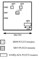
図6は、本実施形態におけるHARQ−ACK PUCCHリソースとSR PUCCHリソースが時間領域においてオーバラップしない例を示す図である。 FIG. 6 is a diagram showing an example in which the HARQ-ACK PUCCH resource and the SR PUCCH resource in the present embodiment do not overlap in the time domain.
図6において、端末装置1には、スロット502で2つのスケジューリングリクエストコンフィギュレーション{SR#0、SR#1}が上位層の信号から設定される。即ち、上位層の信号から設定されている2つのスケジューリングリクエストコンフィギュレーションのそれぞれはSR#0、および、SR#1に対応する。スロット502において、SR#0は、SR PUCCHリソースs004、および、s005を有する。スロット502において、SR#1は、SR PUCCHリソースs102を有する。リソースh002はスロット502におけるHARQ−ACK PUCCHリソースである。時間領域において、t002はPUCCHフォーマットの送信が行われるタイムユニットである。
In FIG. 6, in the
例えば、スロット502において、端末装置1はPUCCHフォーマット2または3を用いてHARQ−ACKフィードバックをリソースh002で送信する。タイムユニットt002において、SR#0が有するSR PUCCHリソース{s004、s005}、および、SR#1が有するSR PUCCHリソースs102は、HARQ−ACK PUCCHリソースと時間領域においてオーバラップしていない。この場合、スケジューリングリクエストビットOSRのサイズは、0で与えられてもよい。この場合、端末装置
1は、HARQ−ACK PUCCHリソースh002、および、PUCCHフォーマット2またはPUCCHフォーマット3を用いてHARQ−ACKのみを送信してもよい。
For example, in
以下、図7を用いて、HARQ−ACK PUCCHリソースとSR PUCCHリソースが時間領域においてオーバラップした場合、スケジューリングリクエストビットOSRの生成に用いられる第1の決定方法と第2の決定方法について説明する。図7は、本実施形態におけるHARQ−ACK PUCCHリソースとSR PUCCHリソースが時間領域においてオーバラップした時スケジューリングリクエストビットのサイズを決定する一例を示す図である。 Hereinafter, with reference to FIG. 7, if the HARQ-ACK PUCCH resources and SR PUCCH resource overlap in the time domain, a first method for determining to be used in generating a scheduling request bit O SR and the second determination method will be described .. FIG. 7 is a diagram showing an example of determining the size of the scheduling request bit when the HARQ-ACK PUCCH resource and the SR PUCCH resource in the present embodiment overlap in the time domain.
また、図7において、端末装置1にはスロット501で3つのスケジューリングリクエストコンフィギュレーション{SR#0、SR#1、SR#2}が上位層の信号から設定される。即ち、上位層の信号から設定されている3つのスケジューリングリクエストコンフィギュレーションのそれぞれはSR#0、SR#1、および、SR#2に対応する。スロット501において、SR#0は、SR PUCCHリソースs001、s002、および、s003を有する。スロット501において、SR#1は、SR PUCCHリソースs101を有する。スロット501において、SR#2はSR PUCCHリソースs201を有する。リソースh001はスロット501におけるHARQ−ACK PUCCHリソースである。
Further, in FIG. 7, three scheduling request configurations {
例えば、スロット501において、端末装置1はPUCCHフォーマット2または3を用いてHARQ−ACKフィードバックをリソースh001で送信する。時間領域において、t001はPUCCHフォーマット2またはPUCCHフォーマット3の送信が行われるタイムユニットである。SR#0が有する{s001、s002}、SR#1が有するs101、および、SR#2が有するs201はHARQ−ACK PUCCHリソースh001と時間領域においてオーバラップしてしまう。ここで、SR#0が有するs003はHARQ−ACK PUCCHリソースh001と時間領域においてオーバラップしない。
For example, in
つまり、HARQ−ACKの送信のためのPUCCHリソースが上位層の信号から設定されるSR PUCCHリソースと時間領域においてオーバラップした場合、スケジューリングリクエストビットOSRのサイズは、オーバラップしたSR PUCCHリソースを有するスケジューリングリクエストコンフィギュレーションの数で与えられてもよい。第1の決定方法は、スケジューリングリクエストビットOSRのサイズが、オーバラップしたSR PUCCHリソースを有するスケジューリングリクエストコンフィギュレーションの数にセットされる方法である。つまり、第1の決定方法を用いた場合、スケジューリングリクエストビットOSRのサイズは、オーバラップしたSR PUCCHリソースを有するスケジューリングリクエストコンフィギュレーションの数と同一である。スケジューリングリクエストビットのそれぞれは、オーバラップしたSR PUCCHリソースを有するスケジューリングリクエストコンフィギュレーションのそれぞれに対してスケジューリングリクエストの情報を示すために用いられてもよい。HARQ−ACK PUCCHリソースとSR PUCCHリソースが時間領域においてオーバラップした場合、該オーバラップしたSR PUCCHリソースを有するスケジューリングリクエストコンフィギュレーションの数はK個とする。第1の決定方法を用いて、K個のスケジューリングリクエストコンフィギュレーションに対応させてKビットのビットマップ情報が通知される。ビットマップの情報ビットのそれぞれは、1つのスケジューリングリクエストコンフィギュレーションに対応する。例えば、ビットマップ情報では、正のスケジューリングリクエストに対応するスケジューリングリクエストコンフィギュレーションには“1”がセットされ、負のスケジューリングリクエストに対応するスケジューリングリクエストコンフィギュレーションには“0”がセットされてもよい。 That is, if the PUCCH resource for transmitting the HARQ-ACK is overlap in SR PUCCH resources and time regions set from the signal of the upper layer, the size of the scheduling request bit O SR has the overlapped SR PUCCH resource It may be given by the number of scheduling request configurations. The first method of determining the size of the scheduling request bit O SR is a method that is set to the number of scheduling request configuration with the overlapped SR PUCCH resource. In other words, the case of using the first determination method, the size of the scheduling request bit O SR is equal to the number of scheduling request configuration with the overlapped SR PUCCH resource. Each of the scheduling request bits may be used to indicate scheduling request information for each of the scheduling request configurations with overlapping SR PUCCH resources. When the HARQ-ACK PUCCH resource and the SR PUCCH resource overlap in the time domain, the number of scheduling request configurations having the overlapped SR PUCCH resource is K. Using the first determination method, K-bit bitmap information is notified corresponding to K scheduling request configurations. Each of the information bits in the bitmap corresponds to one scheduling request configuration. For example, in the bitmap information, "1" may be set in the scheduling request configuration corresponding to the positive scheduling request, and "0" may be set in the scheduling request configuration corresponding to the negative scheduling request.
図7において、HARQ−ACK PUCCHリソースh001とオーバラップしたSR PUCCHリソースを有するスケジューリングリクエストコンフィギュレーションの数は3である。即ち、第1の決定方法によって決定されたスケジューリングリクエストビットOSRのサイズは3ビット(OSR(0)、OSR(1)、OSR(2))の情報ビットである。この場合、スケジューリングリクエストビットOSRの情報ビットそれぞれは、スケジューリングリクエストコンフィギュレーションのそれぞれに対応する。例えば、OSR(0)はSR#0に対応してもよい。OSR(1)はSR#1に対応してもよい。OSR(2)はSR#2に対応してもよい。SR#0に対して、スケジューリングリクエストが正のスケジューリングリクエスト(positive SR)である場合、OSR(0)は1にセットされてもよい。また、SR#0に対して、スケジューリングリクエストが負のスケジューリングリクエスト(negative SR)である場合、OSR(0)は0にセットされてもよい。同様に、SR#1に対して、スケジューリングリクエストが正のスケジューリングリクエスト(positive SR)である場合、OSR(1)は1にセットされてもよいし、スケジューリングリクエストが負のスケジューリングリクエスト(negative SR)である場合、OSR(1)は0にセットされてもよい。SR#2に対して、スケジューリングリクエストが正のスケジューリングリクエスト(positive SR)である場合、OSR(2)は1にセットされてもよいし、スケジューリングリクエストが負のスケジューリングリクエスト(negative SR)である場合、OSR(2)は0にセットされてもよい。端末装置1は、PUCCHリソースh001、および、PUCCHフォーマット2またはPUCCHフォーマット3を用いてHARQ−ACKビットとスケジューリングリクエストビットを送信してもよい。これにより、基地局装置3は、送信したビットマップの情報に基づいて、スケジューリングリクエストコンフィギュレーションのそれぞれに対してスケジューリングリクエストの情報を特定することができる。
In FIG. 7, the number of scheduling request configurations having the SR PUCCH resource that overlaps with the HARQ-ACK PUCCH resource h001 is 3. That is, the size of the scheduling request bit O SR determined by the first determination method is an information bit of 3 bits (O SR (0), O SR (1), O SR (2)). In this case, each of the information bits of the scheduling request bit OSR corresponds to each of the scheduling request configurations. For example, O SR (0) may correspond to
第1の決定方法により、K個のスケジューリングリクエストコンフィギュレーションのそれぞれに対してスケジューリングリクエストが示される。第2の決定方法により、オーバラップしたSR PUCCHリソースを有するスケジューリングリクエストコンフィギュレーションの数が所定の数より多かった場合、OSRのサイズを適切なサイズにすることができる。以下、スケジューリングリクエストビットOSRの生成に用いられる第2の決定方法について説明する。 The first determination method presents scheduling requests for each of the K scheduling request configurations. The second determination method, if the number of scheduling request configuration with the overlapped SR PUCCH resource was greater than a predetermined number, it is possible to make the size of the O SR to the appropriate size. Hereinafter, the second determination method used for generating the scheduling request bit OSR will be described.
第2の決定方法は、スケジューリングリクエストビットOSRのサイズが、オーバラップしたSR PUCCHリソースを有するスケジューリングリクエストコンフィギュレーションの数より少ない数にセットされる方法である。例えば、端末装置1は、PUCCHフォーマット2またはPUCCHフォーマット3を用いてHARQ−ACKのためのPUCCHリソースを用いてHARQ−ACKフィードバックを送信してもよい。HARQ−ACK PUCCHリソースとSR PUCCHリソースが時間領域においてオーバラップした場合、該オーバラップしたSR PUCCHリソースを有するスケジューリングリクエストコンフィギュレーションの数はK個とする。第2の決定方法を用いて決定されるスケジューリングリクエストビットOSRのサイズは、Lビットとする。Lの値は、L=Ceiling(log2(K+1))で与えられてもよい。ここで、Ceiling(*)は、数値*を切り上げて*より最も近く大きい整数を出力する関数である。例えば、Kの値が3である場合、Lは2であってもよい。また、例えば、Kの値が4である場合、Lは3であってもよい。また、例えば、Kの値が7である場合、Lは3であってもよい。
The second method of determining the size of the scheduling request bit O SR is a method that is set to the number less than the number of scheduling request configuration with the overlapped SR PUCCH resource. For example, the
スケジューリングリクエストビットOSRのサイズLに対して、コードポイントの組み合わせの数は(2^L)である。(2^L)は2のL乗のことを示す。以下、コードポイントの組み合わせ(2^L)とスケジューリングリクエストコンフィギュレーションKに対してスケジューリングリクエストの情報について説明する。 The number of combinations of code points is (2 ^ L) with respect to the size L of the scheduling request bit OSR. (2 ^ L) indicates 2 to the L power. Hereinafter, the scheduling request information for the code point combination (2 ^ L) and the scheduling request configuration K will be described.
図8は本実施形態に係るスケジューリングリクエストの情報とコードポイントの対応表の一例を示す図である。ここで、スケジューリングリクエストの情報は、スケジューリングリクエストコンフィギュレーションのそれぞれに対して該スケジューリングリクエストが正のスケジューリングリクエストであるか、または、負のスケジューリングリクエストであるかを示す情報である。図8において、HARQ−ACK PUCCHリソースと時間領域においてオーバラップしたSR PUCCHリソースを有するスケジューリングリクエストコンフィギュレーションの数Kは3であってもよい。該スケジューリングリクエストコンフィギュレーションのそれぞれはSR#0、SR#1、および、SR#2に対応する。例えば、インデックスが一番小さいSR#0には優先度が一番高いであってもよい。つまり、最も優先度が高いスケジューリングリクエストコンフィギュレーションがマッピングされる第1のコードポイントとNegative SRがマッピングされる第2のコードポイントのハミング距離が最大となるように、該最も優先度が高いスケジューリングリクエストコンフィギュレーションと該Negative SRがマッピングされてもよい。例えば、該第1のコードポイントと該第2のコードポイントのハミング距離が最大であることによって、該第1のコードポイントと該第2のコードポイントに関する検出エラーの確率低減が期待される。インデックスが一番大きいSR#2には優先度が一番低いであってもよい。図8において、スケジューリングリクエストビットOSRのサイズLは2ビットであり、4つのコードポイント(4つの状態)に対応できる。図8において、スケジューリングリクエストビットOSRは、{OSR(0)、OSR(1)}である。図8において、‘Positive’は正のスケジューリングリクエストを意味する。‘Negative’は負のスケジューリングリクエストを意味する。‘Any’は正のスケジューリングリクエストと負のスケジューリングリクエストの内どれでもよいことを意味する。
FIG. 8 is a diagram showing an example of a correspondence table between the scheduling request information and the code points according to the present embodiment. Here, the scheduling request information is information indicating whether the scheduling request is a positive scheduling request or a negative scheduling request for each of the scheduling request configurations. In FIG. 8, the number K of scheduling request configurations having SR PUCCH resources overlapping in the time domain with HARQ-ACK PUCCH resources may be 3. Each of the scheduling request configurations corresponds to
図8(a)において、K個のスケジューリングリクエストコンフィギュレーションの内、正のスケジューリングリクエストに対応するスケジューリングリクエストコンフィギュレーションの数は、0、または、1である。例えば、複数のスケジューリングリクエストコンフィギュレーションに対してスケジューリングリクエストがトリガされた場合、MAC層は、その中、優先度が一番高いスケジューリングリクエストコンフィギュレーションを選択しスケジューリングリクエストをシグナル(signal)するよう物理層に通知/指示してもよい。そして、物理層は、MAC層からの指示に基づいて、通知されたスケジューリングリクエストコンフィギュレーションに対してスケジューリングリクエストを送信してもよい。つまり、MAC層から通知されたスケジューリングリクエストコンフィギュレーションに対してスケジューリングリクエストは正のスケジューリングリクエストである。それ以外のスケジューリングリクエストコンフィギュレーションに対してスケジューリングリクエストは負のスケジューリングリクエストである。 In FIG. 8A, out of the K scheduling request configurations, the number of scheduling request configurations corresponding to positive scheduling requests is 0 or 1. For example, when a scheduling request is triggered for multiple scheduling request configurations, the MAC layer selects the highest priority scheduling request configuration and signals the scheduling request. You may notify / instruct. Then, the physical layer may send a scheduling request to the notified scheduling request configuration based on the instruction from the MAC layer. That is, the scheduling request is a positive scheduling request for the scheduling request configuration notified from the MAC layer. Scheduling requests are negative scheduling requests for other scheduling request configurations.
図8(a)において、4つコードポイントの内、1つは、K個のスケジューリングリクエストコンフィギュレーションのそれぞれに対してスケジューリングリクエストが負のスケジューリングリクエストであることを示すために用いられる。他のコードポイントは、正のスケジューリングリクエストに対応するスケジューリングリクエストコンフィギュレーションを示すために用いられる。つまり、正のスケジューリングリクエストに対応するスケジューリングリクエストコンフィグレーションを示す情報をコードポイントにしてもよい。ここで、正のスケジューリングリクエストに対応するスケジューリングリクエストコンフィギュレーションを示す情報をコードポイントにすることは、正のスケジューリングリクエストに対応するスケジューリングリクエストコンフィギュレーションを示す情報に基づいてコードポイントを選択することであってもよい。基地局装置3は、端末装置1から通知したコードポイントに基づいて、スケジューリングリクエストコンフィギュレーションに対してスケジューリングリクエストの情報を判断することができる。例えば、図8(a)において、“00”とセットされるOSR(0)OSR(1)は、SR#0、S
R#1、および、SR#2のそれぞれに対してスケジューリングリクエストが負のスケジューリングリクエストであることを示すために用いられてもよい。“01”とセットされるOSR(0)OSR(1)は、SR#0、および、SR#1のそれぞれに対してスケジューリングリクエストが負のスケジューリングリクエストであることを示し、SR#2に対してスケジューリングリクエストが正のスケジューリングリクエストであることを示すために用いられてもよい。“10”とセットされるOSR(0)OSR(1)は、SR#0、および、SR#2のそれぞれに対してスケジューリングリクエストが負のスケジューリングリクエストであることを示し、SR#1に対してスケジューリングリクエストが正のスケジューリングリクエストであることを示すために用いられてもよい。“11”とセットされるOSR(0)OSR(1)は、SR#1、および、SR#2のそれぞれに対してスケジューリングリクエストが負のスケジューリングリクエストであることを示し、SR#0に対してスケジューリングリクエストが正のスケジューリングリクエストであることを示すために用いられてもよい。
In FIG. 8A, one of the four code points is used to indicate that the scheduling request is a negative scheduling request for each of the K scheduling request configurations. Other code points are used to indicate the scheduling request configuration that corresponds to the positive scheduling request. That is, the code point may be information indicating the scheduling request configuration corresponding to the positive scheduling request. Here, to set the information indicating the scheduling request configuration corresponding to the positive scheduling request as the code point is to select the code point based on the information indicating the scheduling request configuration corresponding to the positive scheduling request. You may. The
It may be used to indicate that the scheduling request is a negative scheduling request for each of
図8(b)において、K個スケジューリングリクエストコンフィギュレーションの内、正のスケジューリングリクエストに対応するスケジューリングリクエストコンフィギュレーションの数は、0、1、または、1より多い数であってもよい。例えば、複数のスケジューリングリクエストコンフィギュレーションに対してスケジューリングリクエストがトリガされた場合、MAC層は、トリガされた複数のスケジューリングリクエストコンフィギュレーションのそれぞれに対してスケジューリングリクエストをシグナル(signal)するよう物理層に通知/指示してもよい。そして、物理層は、MAC層からの指示に基づいて、通知されたスケジューリングリクエストコンフィギュレーションに対してスケジューリングリクエストを送信してもよい。つまり、HARQ−ACK PUCCHリソースの時間領域において、正のスケジューリングリクエストに対応するスケジューリングリクエストコンフィギュレーションの数は複数であってもよい。 In FIG. 8B, among the K scheduling request configurations, the number of scheduling request configurations corresponding to positive scheduling requests may be 0, 1, or more than 1. For example, if a scheduling request is triggered for multiple scheduling request configurations, the MAC layer notifies the physical layer to signal the scheduling request to each of the triggered multiple scheduling request configurations. / You may instruct. Then, the physical layer may send a scheduling request to the notified scheduling request configuration based on the instruction from the MAC layer. That is, there may be a plurality of scheduling request configurations corresponding to positive scheduling requests in the time domain of the HARQ-ACK PUCCH resource.
図8(b)において、4つのコードポイントの内、1つは、SR#0、SR#1、および、SR#2のそれぞれに対してスケジューリングリクエストが負のスケジューリングリクエストであることを示すために用いられる。他のコードポイントは、正のスケジューリングリクエストに対応するスケジューリングリクエストコンフィギュレーションの内、最も優先度が高いスケジューリングコンフィギュレーションを示すために用いられる。図8(b)において、“00”とセットされるOSR(0)OSR(1)は、SR#0、SR#1、および、SR#2のそれぞれに対してスケジューリングリクエストが負のスケジューリングリクエストであることを示すために用いられてもよい。“01”とセットされるOSR(0)OSR(1)は、SR#2に対してスケジューリングリクエストが正のスケジューリングリクエストであることを示し、SR#2より優先度が高いSR#0とSR#1のそれぞれに対してスケジューリングリクエストが負のスケジューリングリクエストであることを示すために用いられてもよい。“10”とセットされるOSR(0)OSR(1)は、SR#1に対してスケジューリングリクエストが正のスケジューリングリクエストであることを示し、SR#1より優先度が高いSR#0に対してスケジューリングリクエストが負のスケジューリングリクエストであることを示し、SR#1より優先度が低いSR#2に対してスケジューリングリクエストの情報を示さなくてもよい。“11”とセットされるOSR(0)OSR(1)は、SR#0に対してスケジューリングリクエストが正のスケジューリングリクエストであることを示し、SR#0より優先度が低いSR#1とSR#2に対してスケジューリングリクエストの情報を示さなくてもよい。これにより、基地局装置3は、正のスケジューリングリクエストに対するスケジューリングリクエストコンフィギュレーションの内、優先度が一番高いスケジューリングリクエストコンフィギュレーションを知ることができる。
In FIG. 8B, one of the four code points is to indicate that the scheduling request is a negative scheduling request for each of
また、HARQ−ACKフィードバックのビット数が所定の値以下である場合に、OS
RのサイズLはHARQ−ACK PUCCHリソースと時間領域においてオーバラップしたSR PUCCHリソースを有するスケジューリングリクエストコンフィギュレーションの数に関わらず1であってもよい。該所定の値は、例えば11ビットであってもよい。OSRのサイズL=1である場合、最も優先度が高いロジカルチャネルに関連するスケジューリングリクエストが送信されてもよい。OSRのサイズL=1である場合、最も優先度が低いロジカルチャネルに関連するスケジューリングリクエストが送信されてもよい。
Further, when the number of bits of the HARQ-ACK feedback is below a predetermined value, O S
The size L of R may be 1 regardless of the number of scheduling request configurations that have SR PUCCH resources that overlap the HARQ-ACK PUCCH resource in the time domain. The predetermined value may be, for example, 11 bits. O If SR is size L = 1, the scheduling request relating to the highest priority logical channel may be transmitted. O If SR is size L = 1, the scheduling request the highest priority is associated with lower logical channel may be transmitted.
また、本実施形態の別の態様として、端末装置1がPUCCHフォーマット4とHARQ−ACK PUCCHリソースを用いてHARQ−ACKフィードバックを送信する時に、HARQ−ACK PUCCHリソースとSR PUCCHリソースが時間領域においてオーバラップした場合、スケジューリングリクエストビットOSRのサイズは、オーバラップしたSR PUCCHリソースを有するスケジューリングリクエストコンフィギュレーションの数に基づかず、1で与えられてもよい。つまり、オーバラップしたSR PUCCHリソースを有するスケジューリングリクエストコンフィギュレーションの数が1より多い場合であっても、端末装置1は、スケジューリングリクエストビットOSRのサイズを1でセットしてもよい。
Further, as another aspect of the present embodiment, when the
また、端末装置1がHARQ−ACK PUCCHリソース、および、PUCCHフォーマット2または3を用いてHARQ−ACKフィードバックを送信する時に、HARQ−ACK PUCCHリソースとSR PUCCHリソースが時間領域においてオーバラップした場合、スケジューリングリクエストビットOSRのサイズは、オーバラップしたSR PUCCHリソースを有するスケジューリングリクエストコンフィギュレーションの数に基づいて、与えられてもよい。つまり、オーバラップしたSR PUCCHリソースを有するスケジューリングリクエストコンフィギュレーションの数が1より多い場合であっても、端末装置1は、スケジューリングリクエストビットOSRのサイズを1より多いビットでセットしてもよい。
Further, when the
以下、本実施形態の別の態様として、端末装置1がHARQ−ACK PUCCHリソースを用いてHARQ−ACKフィードバックを送信する時に、HARQ−ACK PUCCHリソースとSR PUCCHリソースが時間領域においてオーバラップした場合、スケジューリングリクエストビットのサイズを決定する他の一例を説明する。
Hereinafter, as another aspect of the present embodiment, when the
前述したように、第1の決定方法は、スケジューリングリクエストビットOSRのサイズが、HARQ−ACK PUCCHリソースと時間領域においてオーバラップしたSR
PUCCHリソースを有するスケジューリングリクエストコンフィギュレーションの数にセットされる方法である。また、第1の決定方法は、スケジューリングリクエストビットOSRのサイズが、HARQ−ACK PUCCHリソースと時間領域においてオーバラップしたSR PUCCHリソースを有するスケジューリングリクエストコンフィギュレーションの数と関わらず、上位層の信号から設定されているスケジューリングリクエストコンフィギュレーションの数にセットされる方法であってもよい。
As described above, the first method of determining the size of the scheduling request bit O SR was overlap in HARQ-ACK PUCCH resources and time region SR
A method that is set to the number of scheduling request configurations that have PUCCH resources. The first method of determining the size of the scheduling request bit O SR, regardless of the number of scheduling request configuration with SR PUCCH resource overlap in HARQ-ACK PUCCH resource and the time domain, the signal of the upper layer The method may be set to the number of scheduling request configurations that have been set.
該スケジューリングリクエストコンフィギュレーションの数は、PUCCHフォーマットごとに上位層の信号より与えられてもよい。 The number of scheduling request configurations may be given by the upper layer signal for each PUCCH format.
第1の決定方法は、スケジューリングリクエストビットOSRのサイズが、HARQ−ACK PUCCHリソースと時間領域においてオーバラップしたSR PUCCHリソースを有するスケジューリングリクエストコンフィギュレーションの数と関わらず、上位層の信号に少なくとも基づきセットされる方法であってもよい。 The first method of determining the size of the scheduling request bit O SR, regardless of the number of scheduling request configuration with SR PUCCH resource overlap in HARQ-ACK PUCCH resource and the time domain, at least based on the signal of the upper layer It may be a set method.
例えば、端末装置1にはN個スケジューリングリクエストコンフィギュレーションが上
位層の信号から設定されている。そして、HARQ−ACKシーケンスと多重されるスケジューリングリクエストビットOSRのサイズは、Nにセットされてもよい。OSRの情報ビットのそれぞれは、上位層の信号から設定されているスケジューリングリクエストコンフィギュレーションの1つに対応する。OSRの情報ビットとスケジューリングリクエストコンフィギュレーションは1対1でマップされる。スケジューリングリクエストビットOSRのそれぞれは、上位層の信号から設定されているスケジューリングリクエストコンフィギュレーションのそれぞれに対してスケジューリングリクエストの情報を示すために用いられてもよい。つまり、端末装置1は、Nビットのビットマップの形式を用いて、基地局装置3にスケジューリングリクエストコンフィギュレーションN個のそれぞれに対してスケジューリングリクエストの情報を通知してもよい。例えば、端末装置1は、HARQ−ACK PUCCHリソースと時間領域においてオーバラップしたSR PUCCHリソースを有するスケジューリングリクエストコンフィギュレーションの内、正のスケジューリングリクエストに対応するスケジューリングリクエストコンフィギュレーションに対応される情報ビットを“1”にセットし、負のスケジューリングリクエストに対応するスケジューリングリクエストコンフィギュレーションに対応される情報ビットを“0”にセットしてもよい。また、端末装置1は、HARQ−ACK PUCCHリソースと時間領域においてオーバラップしたSR PUCCHリソースを有しないスケジューリングリクエストコンフィギュレーションに対応される情報ビットを“0”にセットしてもよい。
For example, N scheduling request configurations are set in the
図9は、本実施形態におけるHARQ−ACK PUCCHリソースとSR PUCCHリソースが時間領域においてオーバラップした時スケジューリングリクエストビットのサイズを決定する他の一例を示す図である。 FIG. 9 is a diagram showing another example of determining the size of the scheduling request bit when the HARQ-ACK PUCCH resource and the SR PUCCH resource in the present embodiment overlap in the time domain.
図9において、端末装置1には3つのスケジューリングリクエストコンフィギュレーション{SR#0、SR#1、SR#2}が上位層の信号から設定される。つまり、上位層の信号から設定されているスケジューリングリクエストコンフィギュレーション数Nは3である。スロット901において、SR#0は、SR PUCCHリソースs006、s007、および、s008を有する。スロット901において、SR#1は、SR PUCCHリソースを有しない。スロット901において、SR#2はSR PUCCHリソースs203を有する。リソースh003はスロット901におけるHARQ−ACK PUCCHリソースである。SR#0が有する{s006、s007}、および、SR#2が有するs203はHARQ−ACK PUCCHリソースh003と時間領域においてオーバラップしてしまう。つまり、HARQ−ACK PUCCHリソースとオーバラップしたSR PUCCHリソースを有するスケジューリングリクエストコンフィギュレーションの数Kは2である。
In FIG. 9, three scheduling request configurations {
図9(a)において、端末装置1は、SR#0に対してスケジューリングリクエストが正のスケジューリングリクエストか負のスケジューリングリクエストかに基づいて、SR#0に対応される情報ビットOSR(0)を“1”または“0”のいずれかにセットする。また、端末装置1は、HARQ−ACK PUCCHリソースと時間領域においてオーバラップしたSR PUCCHリソースを有しないSR#1に対応される情報ビットOSR(1)を“0”にセットしてもよい。端末装置1は、SR#2に対してスケジューリングリクエストが正のスケジューリングリクエストか負のスケジューリングリクエストかに基づいて、SR#2に対応される情報ビットOSR(2)を“1”または“0”のいずれかにセットする。続いて、端末装置1は、図9(b)のようなビットマップの形式を用いて、基地局装置3にスケジューリングリクエストコンフィギュレーション3つのそれぞれに対してスケジューリングリクエストの情報を通知してもよい。例えば、端末装置1は、HARQ−ACK PUCCHリソースを用いて、ビットマップ情報(1、0、0)をHARQ−ACKと多重して、基地局装置3に送信する。基地局装置3は、ビットマップ情
報(1、0、0)に基づいて、SR#0に対してスケジューリングリクエストが正のスケジューリングリクエストを判断し、SR#2に対してスケジューリングリクエストが負のスケジューリングリクエストを判断できる。
In FIG. 9A, the terminal device 1 sets the information bit O SR (0) corresponding to
また、本態様において、第2の決定方法は、スケジューリングリクエストビットOSRのサイズが、上位層の信号から設定されているスケジューリングリクエストコンフィギュレーション数Nより少ない数にセットされる方法である。つまり、スケジューリングリクエストビットOSRのサイズは、HARQ−ACK PUCCHリソースと時間領域においてオーバラップしたSR PUCCHリソースを有するスケジューリングリクエストコンフィギュレーションの数Kと関わらず、上位層の信号から設定されているスケジューリングリクエストコンフィギュレーションの数と関連している。例えば、端末装置1には上位層の信号からN個スケジューリングリクエストコンフィギュレーションが設定されている。そして、HARQ−ACKシーケンスと多重されるスケジューリングリクエストビットOSRのサイズLは、L=Ceiling(log2(N+1))で与えられてもよい。例えば、Nの値が3である場合、Lは2であってもよい。また、例えば、Nの値が4である場合、Lは3であってもよい。また、例えば、Kの値が7である場合、Lは3であってもよい。
Further, in the present embodiment, the second determination method is a method in which the size of the scheduling request bit OSR is set to a number smaller than the number of scheduling request configurations N set from the signal of the upper layer. In other words, the size of the scheduling request bit O SR, regardless to the number K of the scheduling request configuration with SR PUCCH resource overlap in HARQ-ACK PUCCH resource and the time domain, the scheduling request is set from the signal of the upper layer It is related to the number of configurations. For example, the
続いて、本態様における第の決定方法について説明する。端末装置1には3つのスケジューリングリクエストコンフィギュレーション{SR#0、SR#1、SR#2}が上位層の信号から設定される。ここで、Nの値は3である。HARQ−ACKシーケンスと多重されるスケジューリングリクエストビットOSRのサイズLは、L=Ceiling(log2(3+1))に基づいて、2で与えられてもよい。2ビットの情報ビットから4つの組み合わせ(パターン、状態)が構成される。続いて、図8(a)を参照して、説明する。端末装置1は、3つのスケジューリングリクエストコンフィギュレーションに対してスケジューリングリクエストの情報を4つのコードポイントにしてもよい。ここで、スケジューリングリクエストの情報をコードポイントにすることは、スケジューリングリクエストの情報に基づいてコードポイントを選択することであってもよい。例えば、端末装置1は、3つスケジューリングリクエストコンフィギュレーションに対してスケジューリングリクエストが負のスケジューリングリクエストであることを示す情報をコードポイント(例えば、“00”)にしてもよい。また、例えば、端末装置1は、SR#2に対してスケジューリングリクエストが正のスケジューリングリクエストであることを示す情報をコードポイント(例えば、“01”)にしてもよい。また、例えば、端末装置1は、SR#1に対してスケジューリングリクエストが正のスケジューリングリクエストであることを示す情報をコードポイント(例えば、“10”)にしてもよい。また、例えば、端末装置1は、SR#0に対してスケジューリングリクエストが正のスケジューリングリクエストであることを示す情報をコードポイント(例えば、“11”)にしてもよい。
Subsequently, the first determination method in this embodiment will be described. Three scheduling request configurations {
Kの値とNの値が同一である場合、端末装置1は、図8を用いて、上位層の信号から設定されているスケジューリングリクエストコンフィギュレーションに対してスケジューリングリクエストの情報を示してもよい。続いて、Kの値がNの値より小さい場合、コードポイントに示されるスケジューリングリクエストの情報について説明する。例えば、図10(a)を参照すると、Kの値は2である、即ち、HARQ−ACKの送信に用いられるHARQ−ACK PUCCHリソースを時間領域においてオーバラップしたSR PUCCHリソースを有するスケジューリングリクエストコンフィギュレーション(SR#0、SR#2)の数は2である。SR#1が有するSR PUCCHリソースは、HARQ−ACK PUCCHリソースと時間領域においてオーバラップしていない。この場合、コードポイントに示されるスケジューリングリクエストの情報の解釈を変更してもよい。例えば、図10(a)の示すように、端末装置1は、SR#0とSR#2に対してスケジューリングリクエストが負のスケジューリングリクエストであることを示す情報をコード
ポイント(例えば、“00”)にしてもよい。また、例えば、端末装置1は、SR#2に対してスケジューリングリクエストが正のスケジューリングリクエストであることを示す情報をコードポイント(例えば、“01”)にしてもよい。また、例えば、端末装置1は、SR#0に対してスケジューリングリクエストが正のスケジューリングリクエストであることを示す情報をコードポイント(例えば、“10”)にしてもよい。ここで、端末装置1は、2つのスケジューリングリクエストコンフィギュレーション(SR#0、SR#2)に対するスケジューリングリクエストの情報を示すために、3つのコードポイントを用いてもよい。そして、余った1つのコードポイント“11”は、スケジューリングリクエストの情報を示すために用いられなくてもよい。つまり、端末装置1は、“11”にセットされるコードポイントを基地局装置3へ通知しなくてもよい。また、端末装置1は、“11”にセットされるコードポイントを再解釈してもよい。例えば、端末装置1は、SR#0とSR#2のそれぞれに対してスケジューリングリクエストが正のスケジューリングリクエストであることを示す情報をコードポイント(“11”)にしてもよい。また、図10(b)のように、3つのコードポイントは、SR#0とSR#2に対してスケジューリングリクエストの情報を示すために用いられることができる。この3つのコードポイントはSR#1に対してスケジューリングリクエストが負のスケジューリングリクエストであることを示してもよい。そして、余った1つのコードポイント“11”は、スケジューリングリクエストの情報を示すために用いられなくてもよい。これにより、基地局装置3は、端末装置1から通知したコードポイントに基づいて、スケジューリングリクエストコンフィギュレーションに対してスケジューリングリクエストの情報を判断することができる。
When the value of K and the value of N are the same, the
以下、本発明の端末装置1の装置構成について説明する。
Hereinafter, the device configuration of the
図11は、本実施形態における端末装置1の構成を示す概略ブロック図である。図示するように、端末装置1は、上位層処理部101、制御部103、受信部105、送信部107および、送受信アンテナ109の少なくとも1つを含んで構成される。上位層処理部101は、無線リソース制御部1011、スケジューリング部1013の少なくとも1つを含んで構成される。受信部105は、復号化部1051、復調部1053、多重分離部1055、無線受信部1057とチャネル測定部1059の少なくとも1つを含んで構成される。送信部107は、符号化部1071、共有チャネル生成部1073、制御チャネル生成部1075、多重部1077、無線送信部1079と上りリンク参照信号生成部10711の少なくとも1つを含んで構成される。
FIG. 11 is a schematic block diagram showing the configuration of the
上位層処理部101は、ユーザの操作等により生成された上りリンクデータを、送信部107に出力する。また、上位層処理部101は、媒体アクセス制御(MAC: Medium Access Control)層、パケットデータ統合プロトコル(Packet Data Convergence Protocol: PDCP)層、無線リンク制御(Radio Link Control: RLC)層、無線リソース制御(Radio Resource Control: RRC)層の処理を行なう。また、上位層処理部101は制御チャネルで受信された下りリンク制御情報などに基づき、受信部105、および送信部107の制御を行なうために制御情報を生成し、制御部103に出力する。
The upper
上位層処理部101が備える無線リソース制御部1011は、自装置の各種設定情報の管理を行なう。例えば、無線リソース制御部1011は、設定されたサービングセルの管理を行なう。また、無線リソース制御部1011は、上りリンクの各チャネルに配置される情報を生成し、送信部107に出力する。無線リソース制御部1011は、受信した下りリンクデータの復号に成功した場合には、ACKを生成し送信部107にACKを出力し、受信した下りリンクデータの復号に失敗した場合には、NACKを生成し、送信部107にNACKを出力する。
The radio
上位層処理部101が備えるスケジューリング部1013は、受信部105を介して受信した下りリンク制御情報を記憶する。スケジューリング部1013は、上りリンクグラントを受信したサブフレームから4つ後のサブフレームにおいて、受信された上りリンクグラントに従ってPUSCHを送信するよう、制御部103を介して送信部107を制御する。スケジューリング部1013は、下りリンクグラントを受信したサブフレームにおいて、受信された下りリンクグラントに従って共有チャネルを受信するよう、制御部103を介して受信部105を制御する。
The
制御部103は、上位層処理部101からの制御情報に基づいて、受信部105、および送信部107の制御を行なう制御信号を生成する。制御部103は、生成した制御信号を受信部105、および送信部107に出力して受信部105、および送信部107の制御を行なう。
The
受信部105は、制御部103から入力された制御信号に従って、送受信アンテナ109を介して基地局装置3から受信した受信信号を、分離、復調、復号し、復号した情報を上位層処理部101に出力する。
The receiving
無線受信部1057は、送受信アンテナ109を介して受信した下りリンクの信号を直交復調し、直交復調されたアナログ信号をディジタル信号に変換する。例えば、無線受信部1057は、ディジタル信号に対して高速フーリエ変換(Fast Fourier Transform: FFT)を行い、周波数領域の信号を抽出してもよい。
The
多重分離部1055は、抽出した信号を制御チャネル、共有チャネル、および、参照信号チャネルに、それぞれ分離する。多重分離部1055は、分離した参照信号チャネルをチャネル測定部1059に出力する。
The
復調部1053は、制御チャネル、および、共有チャネルに対して、QPSK、16QAM(Quadrature Amplitude Modulation)、64QAM等の変調方式に対する復調を行ない、復号化部1051へ出力する。
The
復号化部1051は、下りリンクデータの復号を行い、復号した下りリンクデータを上位層処理部101へ出力する。チャネル測定部1059は、参照信号チャネルから下りリンクの伝搬路の推定値を算出し、多重分離部1055へ出力する。チャネル測定部1059は、チャネル状態情報を算出し、尚且つ、チャネル状態情報を上位層処理部101へ出力する。
The
送信部107は、制御部103から入力された制御信号に従って、上りリンク参照信号チャネルを生成し、上位層処理部101から入力された上りリンクデータや上りリンク制御情報を符号化および変調し、共有チャネル、制御チャネル、参照信号チャネルを多重し、送受信アンテナ109を介して基地局装置3に送信する。
The
符号化部1071は、上位層処理部101から入力された上りリンク制御情報と上りリンクデータを符号化し、符号化ビットを共有チャネル生成部1073および/または制御チャネル生成部1075に出力する。
The
共有チャネル生成部1073は、符号化部1071から入力された符号化ビットを変調して変調シンボルを生成し、変調シンボルをDFTすることによって共有チャネルを生成し、多重部1077へ出力してもよい。共有チャネル生成部1073は、符号化部1071から入力された符号化ビットを変調して共有チャネルを生成し、多重部1077へ出力してもよい。
The shared
制御チャネル生成部1075は、符号化部1071から入力された符号化ビット、および/または、SRに基づいて、制御チャネルを生成し、多重部1077へ出力する。
The control
上りリンク参照信号生成部10711は上りリンク参照信号を生成し、生成した上りリンク参照信号を多重部1077へ出力する。
The uplink reference
多重部1077は、制御部103から入力された制御信号に従って、共有チャネル生成部1073から入力された信号および/または制御チャネル生成部1075から入力された信号、および/または、上りリンク参照信号生成部10711から入力された上りリンク参照信号を、送信アンテナポート毎に上りリンクのリソースエレメントに多重する。
The
無線送信部1079は、多重された信号を逆高速フーリエ変換(Inverse Fast Fourier
Transform: IFFT)を行い、ベースバンドのディジタル信号を生成し、ベースバンドのディジタル信号をアナログ信号に変換し、アナログ信号から中間周波数の同相成分および直交成分を生成し、中間周波数帯域に対する余分な周波数成分を除去し、中間周波数の信号を高周波数の信号に変換(アップコンバート: up convert)し、余分な周波数成分を除去し、電力増幅し、送受信アンテナ109に出力して送信する。
The
Transform: IFFT) to generate a baseband digital signal, convert the baseband digital signal to an analog signal, generate intermediate frequency in-phase and quadrature components from the analog signal, and generate extra frequencies for the intermediate frequency band. The component is removed, the intermediate frequency signal is converted to a high frequency signal (up convert), the excess frequency component is removed, the power is amplified, and the signal is output to the transmission /
以下、本発明の基地局装置3の装置構成について説明する。
Hereinafter, the device configuration of the
図12は、本実施形態における基地局装置3の構成を示す概略ブロック図である。図示するように、基地局装置3は、上位層処理部301、制御部303、受信部305、送信部307、および、送受信アンテナ309、を含んで構成される。また、上位層処理部301は、無線リソース制御部3011とスケジューリング部3013を含んで構成される。また、受信部305は、データ復調/復号部3051、制御情報復調/復号部3053、多重分離部3055、無線受信部3057とチャネル測定部3059を含んで構成される。また、送信部307は、符号化部3071、変調部3073、多重部3075、無線送信部3077と下りリンク参照信号生成部3079を含んで構成される。
FIG. 12 is a schematic block diagram showing the configuration of the
上位層処理部301は、媒体アクセス制御(MAC: Medium Access Control)層、パケットデータ統合プロトコル(Packet Data Convergence Protocol: PDCP)層、無線リンク制御(Radio Link Control: RLC)層、無線リソース制御(Radio Resource Control: RRC)層の処理を行なう。また、上位層処理部301は、受信部305、および送信部307の制御を行なうために制御情報を生成し、制御部303に出力する。
The upper
上位層処理部301が備える無線リソース制御部3011は、下りリンクの共有チャネルに配置される下りリンクデータ、RRC signaling、MAC CE(Control Element)を生成し、又は上位ノードから取得し、HARQ制御部3013に出力する。また、無線リソース制御部3011は、端末装置1各々の各種設定情報の管理をする。例えば、無線リソース制御部3011は、端末装置1に設定したサービングセルの管理などを行なう。
The radio
上位層処理部301が備えるスケジューリング部3013は、端末装置1に割り当てる共有チャネルや制御チャネルの無線リソースの管理をしている。スケジューリング部3013は、端末装置1に共有チャネルの無線リソースを割り当てた場合には、共有チャネルの無線リソースの割り当てを示す上りリンクグラントを生成し、生成した上りリンクグラントを送信部307へ出力する。
The scheduling unit 3013 included in the upper
制御部303は、上位層処理部301からの制御情報に基づいて、受信部305、およ
び送信部307の制御を行なう制御信号を生成する。制御部303は、生成した制御信号を受信部305、および送信部307に出力して受信部305、および送信部307の制御を行なう。
The
受信部305は、制御部303から入力された制御信号に従って、送受信アンテナ309を介して端末装置1から受信した受信信号を分離、復調、復号し、復号した情報を上位層処理部301に出力する。
The receiving
無線受信部3057は、送受信アンテナ309を介して受信された上りリンクの信号を直交復調し、直交復調されたアナログ信号をディジタル信号に変換する。無線受信部3057は、ディジタル信号に対して高速フーリエ変換(Fast Fourier Transform: FFT)を行い、周波数領域の信号を抽出し多重分離部3055に出力する。
The
多重分離部1055は、無線受信部3057から入力された信号を制御チャネル、共有チャネル、参照信号チャネルなどの信号に分離する。尚、この分離は、予め基地局装置3が無線リソース制御部3011で決定し、各端末装置1に通知した上りリンクグラントに含まれる無線リソースの割り当て情報に基づいて行なわれる。多重分離部3055は、チャネル測定部3059から入力された伝搬路の推定値から、制御チャネルと共有チャネルの伝搬路の補償を行なう。また、多重分離部3055は、分離した参照信号チャネルをチャネル測定部3059に出力する。
The
多重分離部3055は、分離した制御チャネルと共有チャネルから、上りリンクデータの変調シンボルと上りリンク制御情報(HARQ−ACK)の変調シンボルを取得する。多重分離部3055は、共有チャネルの信号から取得した上りリンクデータの変調シンボルをデータ復調/復号部3051へ出力する。多重分離部3055は、制御チャネルまたは共有チャネルから取得した上りリンク制御情報(HARQ−ACK)の変調シンボルを制御情報復調/復号部3053へ出力する。
The
チャネル測定部3059は、多重分離部3055から入力された上りリンク参照信号から伝搬路の推定値、チャネルの品質などを測定し、多重分離部3055および上位層処理部301に出力する。
The
データ復調/復号部3051は、多重分離部3055から入力された上りリンクデータの変調シンボルから上りリンクデータを復号する。データ復調/復号部3051は、復号された上りリンクデータを上位層処理部301へ出力する。
The data demodulation /
制御情報復調/復号部3053は、多重分離部3055から入力されたHARQ−ACKの変調シンボルからHARQ−ACKを復号する。制御情報復調/復号部3053は、復号したHARQ−ACKを上位層処理部301へ出力する。
The control information demodulation /
送信部307は、制御部303から入力された制御信号に従って、下りリンク参照信号を生成し、上位層処理部301から入力された下りリンク制御情報、下りリンクデータを符号化、および変調し、制御チャネル、共有チャネル、参照信号チャネルを多重して、送受信アンテナ309を介して端末装置1に信号を送信する。
The
符号化部3071は、上位層処理部301から入力された下りリンク制御情報、および、下りリンクデータの符号化を行なう。変調部3073は、符号化部3071から入力された符号化ビットをBPSK、QPSK、16QAM、64QAM等の変調方式で変調する。変調部3073は、変調シンボルにプリコーディングを適用してもよい。プレコーディングは、送信プレコードを含んでもよい。なお、プレコーディングとは、プレコーダが
乗算される(適用される)ことであってもよい。
The
下りリンク参照信号生成部3079は下りリンク参照信号を生成する。多重部3075は、各チャネルの変調シンボルと下りリンク参照信号を多重し、送信シンボルを生成する。
The downlink reference
多重部3075は、送信シンボルにプレコーディングを適用してもよい。多重部3075が送信シンボルに適用するプレコーディングは、下りリンク参照信号、および/または、変調シンボルに対して適用されてもよい。また、下りリンク参照信号に適用されるプレコーディングと、変調シンボルに対して適用されるプレコーディングは、同一であってもよいし、異なってもよい。
The
無線送信部3077は、多重された送信シンボルなどを逆高速フーリエ変換(Inverse Fast Fourier Transform: IFFT)して、時間シンボルを生成する。無線送信部3077は、時間シンボルに対してOFDM方式の変調を行い、ベースバンドのディジタル信号を生成し、ベースバンドのディジタル信号をアナログ信号に変換し、アナログ信号から中間周波数の同相成分および直交成分を生成し、中間周波数帯域に対する余分な周波数成分を除去し、中間周波数の信号を高周波数の信号に変換(アップコンバート: up convert)し、余分な周波数成分を除去し、搬送波信号(Carrier signal, Carrier, RF signal等)を生成する。無線送信部3077は、搬送波信号に対して、電力増幅し、送受信アンテナ309に出力して送信する。
The
以下、本実施形態において、端末装置、および、基地局装置の種々の態様について説明する。 Hereinafter, in the present embodiment, various aspects of the terminal device and the base station device will be described.
(1)上記の目的を達成するために、本発明の態様は、以下のような手段を講じた。すなわち、本発明の第1の態様は、端末装置であって、複数のスケジューリングリクエストコンフィギュレーションの設定に用いられる上位層の信号を受信する受信部105と、PUCCHフォーマットおよびHARQ−ACK PUCCHリソースを用いてHARQ−ACKビットとスケジューリングリクエストビットを送信する送信部107と、を備え、前記スケジューリングリクエストコンフィギュレーションそれぞれは、1つ、または、1つより多いロジカルチャネルに対応され、前記複数のスケジューリングリクエストコンフィギュレーションそれぞれはSR PUCCHリソースを有し、前記スケジューリングリクエストビットは、前記HARQ−ACKビットのシーケンスの後ろに付加され、前記HARQ−ACK PUCCHリソースとSR PUCCHリソースが時間領域においてオーバラップした場合、スケジューリングリクエストビットのサイズLの値は、オーバラップした前記SRPUCCHリソースを有するスケジューリングリクエストコンフィギュレーションの数Kに基づいて、与えられる。
(1) In order to achieve the above object, the aspect of the present invention has taken the following measures. That is, the first aspect of the present invention is a terminal device that uses a
(2)また、本発明の第1の態様において、前記Lの値が前記Kの値と同一の値であたえられる場合、前記スケジューリングリクエストビットのそれぞれは、前記K個のスケジューリングリクエストコンフィギュレーションそれぞれに対してスケジューリングリクエストの情報を示すために用いられ、前記スケジューリングリクエストの情報は、前記スケジューリングリクエストが正のスケジューリングリクエストであるか、または、負のスケジューリングリクエストであるかを示す情報である。 (2) Further, in the first aspect of the present invention, when the value of L is the same as the value of K, each of the scheduling request bits is set to each of the K scheduling request configurations. On the other hand, it is used to indicate the information of the scheduling request, and the information of the scheduling request is information indicating whether the scheduling request is a positive scheduling request or a negative scheduling request.
(3)また、本発明の第1の態様において、前記Lの値が前記Kの値より小さい値で与えられる場合、前記K個スケジューリングリクエストコンフィギュレーションの内、何れのスケジューリングリクエストコンフィギュレーションが正のスケジューリングリクエストに対応するかを示すために異なるコードポイントを選択することを特徴する。 (3) Further, in the first aspect of the present invention, when the value of L is given by a value smaller than the value of K, which of the K scheduling request configurations is positive. It features selecting different code points to indicate whether it corresponds to a scheduling request.
(4)また、本発明の第2の態様は、基地局装置であって、複数のスケジューリングリクエストコンフィギュレーションの設定に用いられる上位層の信号を送信する送信部307と、PUCCHフォーマットおよびHARQ−ACK PUCCHリソースを用いてHARQ−ACKビットとスケジューリングリクエストビットを受信する受信部305と、を備え、前記スケジューリングリクエストコンフィギュレーションそれぞれは、1つ、または、1つより多いロジカルチャネルに対応され、前記複数のスケジューリングリクエストコンフィギュレーションそれぞれはSR PUCCHリソースを有し、前記スケジューリングリクエストビットは、前記HARQ−ACKビットのシーケンスの後ろに付加され、前記HARQ−ACK PUCCHリソースとSR PUCCHリソースが時間領域においてオーバラップした場合、スケジューリングリクエストビットOSRのサイズLの値は、オーバラップした前記SRPUCCHリソースを有するスケジューリングリクエストコンフィギュレーションの数Kに基づいて、与えられる。
(4) A second aspect of the present invention is a base station apparatus, which is a
(5)また、本発明の第2の態様において、前記Lの値が前記Kの値と同一の値であたえられる場合、前記スケジューリングリクエストビットのそれぞれは、前記K個のスケジューリングリクエストコンフィギュレーションそれぞれに対してスケジューリングリクエストの情報を示すために用いられ、前記スケジューリングリクエストの情報は、前記スケジューリングリクエストが正のスケジューリングリクエストであるか、または、負のスケジューリングリクエストであるかを示す情報である。 (5) Further, in the second aspect of the present invention, when the value of L is the same as the value of K, each of the scheduling request bits is set to each of the K scheduling request configurations. On the other hand, it is used to indicate the information of the scheduling request, and the information of the scheduling request is information indicating whether the scheduling request is a positive scheduling request or a negative scheduling request.
(6)また、本発明の第2の態様において、前記Lの値が前記Kの値より小さい値で与えられる場合、
前記K個スケジューリングリクエストコンフィギュレーションの内、何れのスケジューリングリクエストコンフィギュレーションが正のスケジューリングリクエストに対応するかを示すために異なるコードポイントを選択することを特徴する。
(6) Further, in the second aspect of the present invention, when the value of L is given by a value smaller than the value of K,
Among the K scheduling request configurations, a different code point is selected to indicate which scheduling request configuration corresponds to a positive scheduling request.
本発明に関わる端末装置1、基地局装置3、で動作するプログラムは、本発明に関わる上記実施形態の機能を実現するように、CPU(Central Processing Unit)等を制御するプログラム(コンピュータを機能させるプログラム)であっても良い。そして、これら装置で取り扱われる情報は、その処理時に一時的にRAM(Random Access Memory)に蓄積され、その後、Flash ROM(Read Only Memory)などの各種ROMやHDD(Hard Disk Drive)に格納され、必要に応じてCPUによって読み出し、修正・書き込みが行われる。
The program that operates in the
尚、上述した実施形態における端末装置1、基地局装置3の一部、をコンピュータで実現するようにしても良い。その場合、この制御機能を実現するためのプログラムをコンピュータが読み取り可能な記録媒体に記録して、この記録媒体に記録されたプログラムをコンピュータシステムに読み込ませ、実行することによって実現しても良い。
The
尚、ここでいう「コンピュータシステム」とは、端末装置1、基地局装置3に内蔵されたコンピュータシステムであって、OSや周辺機器等のハードウェアを含むものとする。また、「コンピュータが読み取り可能な記録媒体」とは、フレキシブルディスク、光磁気ディスク、ROM、CD−ROM等の可搬媒体、コンピュータシステムに内蔵されるハードディスク等の記憶装置のことをいう。
The "computer system" referred to here is a computer system built in the
さらに「コンピュータが読み取り可能な記録媒体」とは、インターネット等のネットワークや電話回線等の通信回線を介してプログラムを送信する場合の通信線のように、短時間、動的にプログラムを保持するもの、その場合のサーバやクライアントとなるコンピュータシステム内部の揮発性メモリのように、一定時間プログラムを保持しているものも含
んでも良い。また上記プログラムは、前述した機能の一部を実現するためのものであっても良く、さらに前述した機能をコンピュータシステムにすでに記録されているプログラムとの組み合わせで実現できるものであっても良い。
Furthermore, a "computer-readable recording medium" is a medium that dynamically holds a program for a short period of time, such as a communication line when a program is transmitted via a network such as the Internet or a communication line such as a telephone line. , In that case, a program that holds a program for a certain period of time, such as a volatile memory inside a computer system that serves as a server or a client, may be included. Further, the above-mentioned program may be a program for realizing a part of the above-mentioned functions, and may be a program for realizing the above-mentioned functions in combination with a program already recorded in the computer system.
また、上述した実施形態における端末装置1、基地局装置3は、複数の装置から構成される集合体(装置グループ)として実現することもできる。装置グループを構成する装置の各々は、上述した実施形態に関わる端末装置1、基地局装置3の各機能または各機能ブロックの少なくとも一つを備えてもよい。装置グループとして、端末装置1、基地局装置3の一通りの各機能または各機能ブロックを有していればよい。また、上述した実施形態に関わる端末装置1、基地局装置3は、集合体としての基地局装置と通信することも可能である。
Further, the
また、上述した実施形態における基地局装置3は、EUTRAN(Evolved Universal Terrestrial Radio Access Network)であってもよい。また、上述した実施形態における基地局装置3は、eNodeBに対する上位ノードの機能の少なくとも一つを有してもよい。
Further, the
また、上述した実施形態における端末装置1、基地局装置3の一部、又は全部を典型的には集積回路であるLSIとして実現してもよいし、チップセットとして実現してもよい。端末装置1、基地局装置3の各機能ブロックは個別にチップ化してもよいし、一部、又は全部を集積してチップ化してもよい。また、集積回路化の手法はLSIに限らず専用回路、又は汎用プロセッサで実現しても良い。また、半導体技術の進歩によりLSIに代替する集積回路化の技術が出現した場合、当該技術による集積回路を用いることも可能である。
Further, a part or all of the
また、上述した実施形態に用いた装置の各機能ブロック、または諸特徴は、電気回路、たとえば、集積回路あるいは複数の集積回路で実装または実行され得る。本明細書で述べられた機能を実行するように設計された電気回路は、汎用用途プロセッサ、デジタルシグナルプロセッサ(DSP)、特定用途向け集積回路(ASIC)、フィールドプログラマブルゲートアレイ(FPGA)、またはその他のプログラマブル論理デバイス、ディスクリートゲートまたはトランジスタロジック、ディスクリートハードウェア部品、またはこれらを組み合わせたものを含んでよい。汎用用途プロセッサは、マイクロプロセッサであってもよいし、従来型のプロセッサ、コントローラ、マイクロコントローラ、またはステートマシンであっても良い。前述した電気回路は、ディジタル回路で構成されていてもよいし、アナログ回路で構成されていてもよい。また、半導体技術の進歩により現在の集積回路に代替する集積回路化の技術が出現した場合、本発明の一又は複数の態様は当該技術による新たな集積回路を用いることも可能である。 Further, each functional block or feature of the device used in the above-described embodiment may be implemented or executed in an electric circuit, for example, an integrated circuit or a plurality of integrated circuits. Electrical circuits designed to perform the functions described herein are general purpose processors, digital signal processors (DSPs), application specific integrated circuits (ASICs), field programmable gate arrays (FPGAs), or others. Programmable logic devices, discrete gate or transistor logic, discrete hardware components, or a combination thereof. The general purpose processor may be a microprocessor, a conventional processor, a controller, a microcontroller, or a state machine. The electric circuit described above may be composed of a digital circuit or an analog circuit. Further, when an integrated circuit technology that replaces the current integrated circuit appears due to advances in semiconductor technology, one or more aspects of the present invention can also use a new integrated circuit according to the technology.
また、上述した実施形態では、通信装置の一例として端末装置を記載したが、本願発明は、これに限定されるものではなく、屋内外に設置される据え置き型、または非可動型の電子機器、たとえば、AV機器、キッチン機器、掃除・洗濯機器、空調機器、オフィス機器、自動販売機、その他生活機器などの端末装置もしくは通信装置にも適用出来る。 Further, in the above-described embodiment, the terminal device is described as an example of the communication device, but the present invention is not limited to this, and the present invention is not limited to this, and is a stationary or non-movable electronic device installed indoors or outdoors. For example, it can be applied to terminal devices or communication devices such as AV equipment, kitchen equipment, cleaning / washing equipment, air conditioning equipment, office equipment, vending machines, and other living equipment.
以上、この発明の実施形態に関して図面を参照して詳述してきたが、具体的な構成はこの実施形態に限られるものではなく、この発明の要旨を逸脱しない範囲の設計変更等も含まれる。また、本発明は、請求項に示した範囲で種々の変更が可能であり、異なる実施形態にそれぞれ開示された技術的手段を適宜組み合わせて得られる実施形態についても本発明の技術的範囲に含まれる。また、上記各実施形態に記載された要素であり、同様の効果を奏する要素同士を置換した構成も含まれる。 Although the embodiments of the present invention have been described in detail with reference to the drawings, the specific configuration is not limited to this embodiment, and design changes and the like within a range not deviating from the gist of the present invention are also included. Further, the present invention can be variously modified within the scope of the claims, and the technical scope of the present invention also includes embodiments obtained by appropriately combining the technical means disclosed in the different embodiments. Is done. In addition, the elements described in each of the above embodiments include a configuration in which elements having the same effect are replaced with each other.
1(1A、1B、1C) 端末装置
3 基地局装置
101 上位層処理部
103 制御部
105 受信部
107 送信部
109 送受信アンテナ
1011 無線リソース制御部
1013 スケジューリング部
1051 復号化部
1053 復調部
1055 多重分離部
1057 無線受信部
1059 チャネル測定部
1071 符号化部
1073 共有チャネル生成部
1075 制御チャネル生成部
1077 多重部
1079 無線送信部
10711 上りリンク参照信号生成部
301 上位層処理部
303 制御部
305 受信部
307 送信部
309 送受信アンテナ
3011 無線リソース制御部
3013 スケジューリング部
3051 データ復調/復号部
3053 制御情報復調/復号部
3055 多重分離部
3057 無線受信部
3059 チャネル測定部
3071 符号化部
3073 変調部
3075 多重部
3077 無線送信部
3079 下りリンク参照信号生成部
1 (1A, 1B, 1C)
Claims (14)
HARQ−ACKの送信のためのPUCCHリソースを用いてHARQ−ACKビットおよびスケジューリングリクエストビットを送信する送信部と、を備え、 A transmitter for transmitting the HARQ-ACK bit and the scheduling request bit using the PUCCH resource for transmitting the HARQ-ACK is provided.
前記1つのスケジューリングリクエストコンフィギュレーションはSR PUCCHリソースを設定し、 The one scheduling request configuration sets the SR PUCCH resource and
前記スケジューリングリクエストビットのサイズLの値は、以下の式に基づいて与えられ、 The value of the size L of the scheduling request bit is given based on the following equation.
loglog 22 (K+1)(K + 1)
Kは、前記PUCCHリソースと時間領域においてオーバラップする少なくとも1つのSR PUCCHリソースに対応するスケジューリングリクエストコンフィギュレーションの数であり、 K is the number of scheduling request configurations corresponding to at least one SR PUCCH resource that overlaps the PUCCH resource in the time domain.
前記スケジューリングリクエストビットは、前記HARQ−ACKビットに付加される The scheduling request bit is added to the HARQ-ACK bit.
端末装置。Terminal equipment.
前記スケジューリングリクエストビットのサイズLの値は、K=1に基づいて与えられる The value of the size L of the scheduling request bit is given based on K = 1.
請求項1に記載する端末装置。The terminal device according to claim 1.
前記スケジューリングリクエストビットのサイズLの値は、K=1に基づいて与えられる The value of the size L of the scheduling request bit is given based on K = 1.
請求項1に記載する端末装置。The terminal device according to claim 1.
K個のスケジューリングリクエストコンフィギュレーションに対応する1つまたは複数のSR PUCCHリソースが、時間領域において前記PUCCHリソースとオーバラップしている第1の場合、 In the first case, one or more SR PUCCH resources corresponding to K scheduling request configurations overlap with the PUCCH resource in the time domain.
前記スケジューリングリクエストビットのサイズLの値は、log The value of the size L of the scheduling request bit is log. 22 (K+1)に基づいて与えられるGiven based on (K + 1)
請求項1に記載する端末装置。The terminal device according to claim 1.
請求項4に記載する端末装置。The terminal device according to claim 4.
請求項1に記載する端末装置。The terminal device according to claim 1.
HARQ−ACKの送信のためのPUCCHリソースを用いてHARQ−ACKビットおよびスケジューリングリクエストビットを受信する受信部と、を備え、 It includes a receiver that receives the HARQ-ACK bit and the scheduling request bit using the PUCCH resource for transmitting the HARQ-ACK.
前記1つのスケジューリングリクエストコンフィギュレーションはSR PUCCHリソースを設定し、 The one scheduling request configuration sets the SR PUCCH resource and
前記スケジューリングリクエストビットのサイズLの値は、以下の式に基づいて与えられ、 The value of the size L of the scheduling request bit is given based on the following equation.
loglog 22 (K+1)(K + 1)
Kは、前記PUCCHリソースと時間領域においてオーバラップする少なくとも1つのSR PUCCHリソースに対応するスケジューリングリクエストコンフィギュレーションの数であり、 K is the number of scheduling request configurations corresponding to at least one SR PUCCH resource that overlaps the PUCCH resource in the time domain.
前記スケジューリングリクエストビットは、前記HARQ−ACKビットに付加される The scheduling request bit is added to the HARQ-ACK bit.
基地局装置。Base station equipment.
前記スケジューリングリクエストビットのサイズLの値は、K=1に基づいて与えられる The value of the size L of the scheduling request bit is given based on K = 1.
請求項7に記載する基地局装置。The base station apparatus according to claim 7.
前記スケジューリングリクエストビットのサイズLの値は、K=1に基づいて与えられる The value of the size L of the scheduling request bit is given based on K = 1.
請求項7に記載する基地局装置。The base station apparatus according to claim 7.
K個のスケジューリングリクエストコンフィギュレーションに対応する1つまたは複数のSR PUCCHリソースが、時間領域において前記PUCCHリソースとオーバラップしている第1の場合、 In the first case, one or more SR PUCCH resources corresponding to K scheduling request configurations overlap with the PUCCH resource in the time domain.
前記スケジューリングリクエストビットのサイズLの値は、log The value of the size L of the scheduling request bit is log. 22 (K+1)に基づいて与えられるGiven based on (K + 1)
請求項7に記載する基地局装置。The base station apparatus according to claim 7.
請求項10に記載する基地局装置。The base station apparatus according to claim 10.
請求項7に記載する基地局装置。The base station apparatus according to claim 7.
HARQ−ACKの送信のためのPUCCHリソースを用いてHARQ−ACKビットおよびスケジューリングリクエストビットを送信し、 The HARQ-ACK bit and the scheduling request bit are transmitted using the PUCCH resource for transmitting the HARQ-ACK, and the HARQ-ACK bit and the scheduling request bit are transmitted.
前記1つのスケジューリングリクエストコンフィギュレーションはSR PUCCHリソースを設定し、 The one scheduling request configuration sets the SR PUCCH resource and
前記スケジューリングリクエストビットのサイズLの値は、以下の式に基づいて与えられ、 The value of the size L of the scheduling request bit is given based on the following equation.
loglog 22 (K+1)(K + 1)
Kは、前記PUCCHリソースと時間領域においてオーバラップする少なくとも1つのSR PUCCHリソースに対応するスケジューリングリクエストコンフィギュレーションの数であり、 K is the number of scheduling request configurations corresponding to at least one SR PUCCH resource that overlaps the PUCCH resource in the time domain.
前記スケジューリングリクエストビットは、前記HARQ−ACKビットに付加される The scheduling request bit is added to the HARQ-ACK bit.
端末装置の通信方法。Communication method of the terminal device.
HARQ−ACKの送信のためのPUCCHリソースを用いてHARQ−ACKビットおよびスケジューリングリクエストビットを受信し、 Receive the HARQ-ACK bit and the scheduling request bit using the PUCCH resource for transmitting the HARQ-ACK,
前記1つのスケジューリングリクエストコンフィギュレーションはSR PUCCHリソースを設定し、 The one scheduling request configuration sets the SR PUCCH resource and
前記スケジューリングリクエストビットのサイズLの値は、以下の式に基づいて与えられ、 The value of the size L of the scheduling request bit is given based on the following equation.
loglog 22 (K+1)(K + 1)
Kは、前記PUCCHリソースと時間領域においてオーバラップする少なくとも1つのSR PUCCHリソースに対応するスケジューリングリクエストコンフィギュレーションの数であり、 K is the number of scheduling request configurations corresponding to at least one SR PUCCH resource that overlaps the PUCCH resource in the time domain.
前記スケジューリングリクエストビットは、前記HARQ−ACKビットに付加される The scheduling request bit is added to the HARQ-ACK bit.
基地局装置の通信方法。Communication method of base station equipment.
Priority Applications (7)
| Application Number | Priority Date | Filing Date | Title |
|---|---|---|---|
| JP2017176818A JP6937202B2 (en) | 2017-09-14 | 2017-09-14 | Terminal equipment, base station equipment, and communication methods |
| US16/645,808 US11265138B2 (en) | 2017-09-14 | 2018-09-11 | Terminal apparatus, base station apparatus, and communication method |
| PCT/JP2018/033707 WO2019054388A1 (en) | 2017-09-14 | 2018-09-11 | Terminal device, base station device, and communication method |
| CN201880058962.9A CN111096024B (en) | 2017-09-14 | 2018-09-11 | Terminal device, base station device, and communication method |
| EP18855632.8A EP3684125B1 (en) | 2017-09-14 | 2018-09-11 | Terminal apparatus, base station apparatus, and communication method |
| BR112020004841-0A BR112020004841A2 (en) | 2017-09-14 | 2018-09-11 | terminal device, base station device and communication method |
| PH12020500471A PH12020500471A1 (en) | 2017-09-14 | 2020-03-09 | Terminal device, base station device, and communication method |
Applications Claiming Priority (1)
| Application Number | Priority Date | Filing Date | Title |
|---|---|---|---|
| JP2017176818A JP6937202B2 (en) | 2017-09-14 | 2017-09-14 | Terminal equipment, base station equipment, and communication methods |
Publications (3)
| Publication Number | Publication Date |
|---|---|
| JP2019054380A JP2019054380A (en) | 2019-04-04 |
| JP2019054380A5 JP2019054380A5 (en) | 2020-07-09 |
| JP6937202B2 true JP6937202B2 (en) | 2021-09-22 |
Family
ID=65722639
Family Applications (1)
| Application Number | Title | Priority Date | Filing Date |
|---|---|---|---|
| JP2017176818A Active JP6937202B2 (en) | 2017-09-14 | 2017-09-14 | Terminal equipment, base station equipment, and communication methods |
Country Status (7)
| Country | Link |
|---|---|
| US (1) | US11265138B2 (en) |
| EP (1) | EP3684125B1 (en) |
| JP (1) | JP6937202B2 (en) |
| CN (1) | CN111096024B (en) |
| BR (1) | BR112020004841A2 (en) |
| PH (1) | PH12020500471A1 (en) |
| WO (1) | WO2019054388A1 (en) |
Families Citing this family (12)
| Publication number | Priority date | Publication date | Assignee | Title |
|---|---|---|---|---|
| US11356987B2 (en) * | 2017-09-30 | 2022-06-07 | Samsung Electronics Co., Ltd. | Method and equipment for transmitting uplink control information and setting uplink time advance |
| CN109600847A (en) * | 2017-09-30 | 2019-04-09 | 北京三星通信技术研究有限公司 | Transmitting uplink control information, the method and apparatus that upstream time lead is set |
| CN114401550A (en) | 2018-01-12 | 2022-04-26 | 华为技术有限公司 | Transmission method of uplink control information, access network equipment and terminal equipment |
| CN110034850B (en) | 2018-01-12 | 2020-10-30 | 电信科学技术研究院有限公司 | Information transmission method, terminal and network equipment |
| CN110035549B (en) * | 2018-01-12 | 2021-03-09 | 电信科学技术研究院有限公司 | Transmission method, terminal and base station |
| US11218993B2 (en) * | 2018-06-29 | 2022-01-04 | Qualcomm Incorporated | Service request prioritization for intra-UE service multiplexing |
| WO2020113433A1 (en) * | 2018-12-04 | 2020-06-11 | Oppo广东移动通信有限公司 | Method and device and terminal for processing scheduling request |
| US20220361199A1 (en) * | 2019-07-01 | 2022-11-10 | Sharp Kabushiki Kaisha | Priority differentiation of sr transmissions with harq-ack codebooks of different service types |
| EP3965509B1 (en) | 2019-07-19 | 2024-04-03 | Guangdong Oppo Mobile Telecommunications Corp., Ltd. | Scheduling request transmission method, terminal device, and network device |
| EP4014372A1 (en) * | 2019-08-15 | 2022-06-22 | Telefonaktiebolaget LM Ericsson (publ) | Wireless device-autonomous pdsch rx antenna adaptation |
| EP4062566A1 (en) * | 2019-11-18 | 2022-09-28 | Telefonaktiebolaget Lm Ericsson (Publ) | Aperiodic scheduling request |
| CN113994754A (en) * | 2020-05-27 | 2022-01-28 | 北京小米移动软件有限公司 | Method, apparatus and computer readable storage medium for transmitting scheduling request |
Family Cites Families (7)
| Publication number | Priority date | Publication date | Assignee | Title |
|---|---|---|---|---|
| US20110268045A1 (en) * | 2010-04-30 | 2011-11-03 | Youn Hyoung Heo | System and method for uplink control information transmission in carrier aggregation |
| WO2012053863A2 (en) | 2010-10-21 | 2012-04-26 | Lg Electronics Inc. | Method and apparatus for transmitting control information in a wireless communication system |
| US9225503B2 (en) * | 2011-05-02 | 2015-12-29 | Lg Electronics Inc. | Method for transmitting/receiving data in wireless communication system and base station for same |
| US9853779B2 (en) * | 2014-01-10 | 2017-12-26 | Sharp Kabushiki Kaisha | Systems and methods for carrier aggregation |
| US10314035B2 (en) * | 2015-01-05 | 2019-06-04 | Apple Inc. | Sub-frame allocation for low power LTE |
| JP2017176818A (en) | 2016-03-28 | 2017-10-05 | 株式会社神戸製鋼所 | Superconducting magnet and manufacturing method of the same |
| US10588047B2 (en) * | 2017-04-10 | 2020-03-10 | Qualcomm Incorporated | Transmission of buffer status reports on multiple component carriers |
-
2017
- 2017-09-14 JP JP2017176818A patent/JP6937202B2/en active Active
-
2018
- 2018-09-11 CN CN201880058962.9A patent/CN111096024B/en active Active
- 2018-09-11 US US16/645,808 patent/US11265138B2/en active Active
- 2018-09-11 BR BR112020004841-0A patent/BR112020004841A2/en unknown
- 2018-09-11 WO PCT/JP2018/033707 patent/WO2019054388A1/en unknown
- 2018-09-11 EP EP18855632.8A patent/EP3684125B1/en active Active
-
2020
- 2020-03-09 PH PH12020500471A patent/PH12020500471A1/en unknown
Also Published As
| Publication number | Publication date |
|---|---|
| JP2019054380A (en) | 2019-04-04 |
| CN111096024A (en) | 2020-05-01 |
| PH12020500471A1 (en) | 2021-01-25 |
| EP3684125B1 (en) | 2023-08-30 |
| US11265138B2 (en) | 2022-03-01 |
| WO2019054388A1 (en) | 2019-03-21 |
| BR112020004841A2 (en) | 2020-09-15 |
| EP3684125A1 (en) | 2020-07-22 |
| CN111096024B (en) | 2023-06-20 |
| US20200280427A1 (en) | 2020-09-03 |
| EP3684125A4 (en) | 2021-06-09 |
Similar Documents
| Publication | Publication Date | Title |
|---|---|---|
| JP6937202B2 (en) | Terminal equipment, base station equipment, and communication methods | |
| JP6652505B2 (en) | Terminal device, base station device, communication method and integrated circuit | |
| JP4928621B2 (en) | Wireless communication system, base station apparatus, mobile station apparatus, wireless communication method, and integrated circuit | |
| JP7101025B2 (en) | Terminal equipment, base station equipment, and communication methods | |
| CN107534965B (en) | Terminal device, base station device, communication method, and integrated circuit | |
| JP6788579B2 (en) | Terminal equipment, base station equipment, and communication methods | |
| JP7075805B2 (en) | Terminal equipment, base station equipment, and communication methods | |
| WO2018030494A1 (en) | Terminal device, base station device, communication method, and integrated circuit | |
| WO2019160026A1 (en) | Terminal device, base station device, and communication method | |
| JP6260031B2 (en) | User apparatus, base station apparatus, integrated circuit, and communication method | |
| US11770843B2 (en) | Terminal apparatus, base station apparatus, and communication method | |
| WO2019151051A1 (en) | Terminal device, base station device, and communication method | |
| JP5469776B2 (en) | Wireless communication system, base station apparatus, mobile station apparatus, wireless communication method, and integrated circuit | |
| JP5415572B2 (en) | Mobile station apparatus, base station apparatus, radio communication method, integrated circuit, and radio communication system | |
| JP2020098946A (en) | Terminal device, base station device, communication method, and integrated circuit | |
| WO2020162299A1 (en) | Terminal device, base station device, and communication method | |
| JP2018137492A (en) | Terminal device, base station device, communication method, and integrated circuit | |
| JP7231775B2 (en) | TERMINAL DEVICE, BASE STATION DEVICE, AND COMMUNICATION METHOD | |
| JP6853863B1 (en) | Terminal equipment, base station equipment, and communication methods | |
| WO2020218415A1 (en) | Terminal device, base station device, and communication method | |
| WO2019131878A1 (en) | Terminal equipment, base station device, and communication method | |
| JP2018196077A (en) | Terminal device, base station device, communication method and integrated circuit |
Legal Events
| Date | Code | Title | Description |
|---|---|---|---|
| A711 | Notification of change in applicant |
Free format text: JAPANESE INTERMEDIATE CODE: A711 Effective date: 20190328 |
|
| RD02 | Notification of acceptance of power of attorney |
Free format text: JAPANESE INTERMEDIATE CODE: A7422 Effective date: 20190328 |
|
| A521 | Request for written amendment filed |
Free format text: JAPANESE INTERMEDIATE CODE: A523 Effective date: 20190605 |
|
| A521 | Request for written amendment filed |
Free format text: JAPANESE INTERMEDIATE CODE: A523 Effective date: 20200519 |
|
| A621 | Written request for application examination |
Free format text: JAPANESE INTERMEDIATE CODE: A621 Effective date: 20200519 |
|
| TRDD | Decision of grant or rejection written | ||
| A01 | Written decision to grant a patent or to grant a registration (utility model) |
Free format text: JAPANESE INTERMEDIATE CODE: A01 Effective date: 20210803 |
|
| A61 | First payment of annual fees (during grant procedure) |
Free format text: JAPANESE INTERMEDIATE CODE: A61 Effective date: 20210830 |
|
| R150 | Certificate of patent or registration of utility model |
Ref document number: 6937202 Country of ref document: JP Free format text: JAPANESE INTERMEDIATE CODE: R150 |