JP6932526B2 - Image display device, image display method and program - Google Patents
Image display device, image display method and program Download PDFInfo
- Publication number
- JP6932526B2 JP6932526B2 JP2017050378A JP2017050378A JP6932526B2 JP 6932526 B2 JP6932526 B2 JP 6932526B2 JP 2017050378 A JP2017050378 A JP 2017050378A JP 2017050378 A JP2017050378 A JP 2017050378A JP 6932526 B2 JP6932526 B2 JP 6932526B2
- Authority
- JP
- Japan
- Prior art keywords
- image
- display
- display element
- correction
- pupil
- Prior art date
- Legal status (The legal status is an assumption and is not a legal conclusion. Google has not performed a legal analysis and makes no representation as to the accuracy of the status listed.)
- Active
Links
- 238000000034 method Methods 0.000 title claims description 18
- 210000001747 pupil Anatomy 0.000 claims description 56
- 238000009826 distribution Methods 0.000 claims description 55
- 210000005252 bulbus oculi Anatomy 0.000 claims description 29
- 238000012937 correction Methods 0.000 claims description 27
- 230000003287 optical effect Effects 0.000 claims description 19
- 210000001508 eye Anatomy 0.000 claims description 16
- 238000003384 imaging method Methods 0.000 claims description 8
- 239000002131 composite material Substances 0.000 claims description 4
- 210000003128 head Anatomy 0.000 claims description 3
- 238000003705 background correction Methods 0.000 description 28
- 238000012545 processing Methods 0.000 description 15
- 230000002093 peripheral effect Effects 0.000 description 12
- 238000010586 diagram Methods 0.000 description 11
- 238000004364 calculation method Methods 0.000 description 5
- 230000006870 function Effects 0.000 description 3
- 238000012546 transfer Methods 0.000 description 3
- 238000004891 communication Methods 0.000 description 2
- 238000004590 computer program Methods 0.000 description 2
- 230000006866 deterioration Effects 0.000 description 2
- 230000000694 effects Effects 0.000 description 2
- 238000003702 image correction Methods 0.000 description 2
- 238000005259 measurement Methods 0.000 description 2
- 238000000691 measurement method Methods 0.000 description 1
- 230000036962 time dependent Effects 0.000 description 1
Images


Classifications
-
- G—PHYSICS
- G09—EDUCATION; CRYPTOGRAPHY; DISPLAY; ADVERTISING; SEALS
- G09G—ARRANGEMENTS OR CIRCUITS FOR CONTROL OF INDICATING DEVICES USING STATIC MEANS TO PRESENT VARIABLE INFORMATION
- G09G5/00—Control arrangements or circuits for visual indicators common to cathode-ray tube indicators and other visual indicators
- G09G5/10—Intensity circuits
-
- G—PHYSICS
- G09—EDUCATION; CRYPTOGRAPHY; DISPLAY; ADVERTISING; SEALS
- G09G—ARRANGEMENTS OR CIRCUITS FOR CONTROL OF INDICATING DEVICES USING STATIC MEANS TO PRESENT VARIABLE INFORMATION
- G09G3/00—Control arrangements or circuits, of interest only in connection with visual indicators other than cathode-ray tubes
- G09G3/001—Control arrangements or circuits, of interest only in connection with visual indicators other than cathode-ray tubes using specific devices not provided for in groups G09G3/02 - G09G3/36, e.g. using an intermediate record carrier such as a film slide; Projection systems; Display of non-alphanumerical information, solely or in combination with alphanumerical information, e.g. digital display on projected diapositive as background
- G09G3/002—Control arrangements or circuits, of interest only in connection with visual indicators other than cathode-ray tubes using specific devices not provided for in groups G09G3/02 - G09G3/36, e.g. using an intermediate record carrier such as a film slide; Projection systems; Display of non-alphanumerical information, solely or in combination with alphanumerical information, e.g. digital display on projected diapositive as background to project the image of a two-dimensional display, such as an array of light emitting or modulating elements or a CRT
-
- G—PHYSICS
- G06—COMPUTING; CALCULATING OR COUNTING
- G06T—IMAGE DATA PROCESSING OR GENERATION, IN GENERAL
- G06T5/00—Image enhancement or restoration
- G06T5/90—Dynamic range modification of images or parts thereof
- G06T5/92—Dynamic range modification of images or parts thereof based on global image properties
-
- G—PHYSICS
- G06—COMPUTING; CALCULATING OR COUNTING
- G06T—IMAGE DATA PROCESSING OR GENERATION, IN GENERAL
- G06T11/00—2D [Two Dimensional] image generation
- G06T11/60—Editing figures and text; Combining figures or text
-
- G—PHYSICS
- G09—EDUCATION; CRYPTOGRAPHY; DISPLAY; ADVERTISING; SEALS
- G09G—ARRANGEMENTS OR CIRCUITS FOR CONTROL OF INDICATING DEVICES USING STATIC MEANS TO PRESENT VARIABLE INFORMATION
- G09G2320/00—Control of display operating conditions
- G09G2320/02—Improving the quality of display appearance
- G09G2320/0233—Improving the luminance or brightness uniformity across the screen
-
- G—PHYSICS
- G09—EDUCATION; CRYPTOGRAPHY; DISPLAY; ADVERTISING; SEALS
- G09G—ARRANGEMENTS OR CIRCUITS FOR CONTROL OF INDICATING DEVICES USING STATIC MEANS TO PRESENT VARIABLE INFORMATION
- G09G2320/00—Control of display operating conditions
- G09G2320/04—Maintaining the quality of display appearance
- G09G2320/043—Preventing or counteracting the effects of ageing
- G09G2320/046—Dealing with screen burn-in prevention or compensation of the effects thereof
-
- G—PHYSICS
- G09—EDUCATION; CRYPTOGRAPHY; DISPLAY; ADVERTISING; SEALS
- G09G—ARRANGEMENTS OR CIRCUITS FOR CONTROL OF INDICATING DEVICES USING STATIC MEANS TO PRESENT VARIABLE INFORMATION
- G09G2320/00—Control of display operating conditions
- G09G2320/06—Adjustment of display parameters
- G09G2320/0686—Adjustment of display parameters with two or more screen areas displaying information with different brightness or colours
-
- G—PHYSICS
- G09—EDUCATION; CRYPTOGRAPHY; DISPLAY; ADVERTISING; SEALS
- G09G—ARRANGEMENTS OR CIRCUITS FOR CONTROL OF INDICATING DEVICES USING STATIC MEANS TO PRESENT VARIABLE INFORMATION
- G09G2340/00—Aspects of display data processing
- G09G2340/12—Overlay of images, i.e. displayed pixel being the result of switching between the corresponding input pixels
-
- G—PHYSICS
- G09—EDUCATION; CRYPTOGRAPHY; DISPLAY; ADVERTISING; SEALS
- G09G—ARRANGEMENTS OR CIRCUITS FOR CONTROL OF INDICATING DEVICES USING STATIC MEANS TO PRESENT VARIABLE INFORMATION
- G09G2340/00—Aspects of display data processing
- G09G2340/14—Solving problems related to the presentation of information to be displayed
-
- G—PHYSICS
- G09—EDUCATION; CRYPTOGRAPHY; DISPLAY; ADVERTISING; SEALS
- G09G—ARRANGEMENTS OR CIRCUITS FOR CONTROL OF INDICATING DEVICES USING STATIC MEANS TO PRESENT VARIABLE INFORMATION
- G09G2354/00—Aspects of interface with display user
-
- G—PHYSICS
- G09—EDUCATION; CRYPTOGRAPHY; DISPLAY; ADVERTISING; SEALS
- G09G—ARRANGEMENTS OR CIRCUITS FOR CONTROL OF INDICATING DEVICES USING STATIC MEANS TO PRESENT VARIABLE INFORMATION
- G09G2370/00—Aspects of data communication
- G09G2370/16—Use of wireless transmission of display information
Landscapes
- Engineering & Computer Science (AREA)
- Physics & Mathematics (AREA)
- General Physics & Mathematics (AREA)
- Theoretical Computer Science (AREA)
- Computer Hardware Design (AREA)
- Controls And Circuits For Display Device (AREA)
- Indication In Cameras, And Counting Of Exposures (AREA)
- Transforming Electric Information Into Light Information (AREA)
- Control Of Indicators Other Than Cathode Ray Tubes (AREA)
Description
本発明は、画像表示装置の表示光学系によって発生する輝度分布のムラを補正する技術に関する。 The present invention relates to a technique for correcting unevenness of luminance distribution caused by a display optical system of an image display device.
従来から、使用者(ユーザ)の左右両眼それぞれに対して設けられた表示部に画像を表示する頭部装着型画像表示装置(HMD:Head Mounted Display)が知られている。HMDのような画像表示装置では、高解像度で広画角であること、また頭部に装着しても違和感や疲労感が少ない小型軽量であることが求められる。しかし、一般的に、高解像度で広画角であるほど、また装置のサイズや重量を小型軽量にするほど、光学系を主とする原因によって画像の輝度分布にムラが発生する。 Conventionally, a head-mounted image display device (HMD: Head Mounted Display) that displays an image on a display unit provided for each of the left and right eyes of a user (user) has been known. An image display device such as an HMD is required to have a high resolution and a wide angle of view, and to be compact and lightweight with little discomfort or fatigue even when worn on the head. However, in general, the higher the resolution and the wider angle of view, and the smaller and lighter the size and weight of the device, the more uneven the brightness distribution of the image occurs due to the cause mainly of the optical system.
このような問題に対して、特許文献1には、表示部の光学性能情報である画像シェーディング等に基づいて、表示部に表示すべき画像を補正する技術が開示されている。 To solve such a problem, Patent Document 1 discloses a technique for correcting an image to be displayed on the display unit based on image shading or the like, which is optical performance information of the display unit.
しかしながら、特許文献1には、どのように設計された画像シェーディングにも続いて画像を補正するのか記載がなく、ユーザが画像の周辺領域を観察する場合に、画像の中央領域と周辺領域とを見比べて輝度分布にムラがあると認識してしまう場合があった。そこで、本発明は、画像の中央領域と周辺領域とで輝度分布のムラを軽減することを目的とする。 However, Patent Document 1 does not describe how to correct the image following the designed image shading, and when the user observes the peripheral region of the image, the central region and the peripheral region of the image are defined. In some cases, it was recognized that the brightness distribution was uneven by comparison. Therefore, an object of the present invention is to reduce unevenness in the luminance distribution between the central region and the peripheral region of the image.
上記課題を解決するために、本発明は、画像表示装置に、画像を表示する表示素子と、複数の補正テーブルから選択された1つの補正テーブルを用いて、前記表示素子が表示する画像の輝度を補正する補正手段と、を有し、前記複数の補正テーブルは、前記射出瞳の位置にユーザの眼球の瞳孔を置いた場合に、当該射出瞳の位置から前記ユーザの眼球の回転中心に相当する位置に向かう方向において、当該回転中心に相当する位置近傍の複数の位置に撮像装置の入射瞳を配置して撮像された前記表示素子の画像の複数の輝度分布に基づいて生成されることを特徴とする。 In order to solve the above problems, the present invention uses a display element for displaying an image and one correction table selected from a plurality of correction tables in an image display device, and the brightness of the image displayed by the display element. The plurality of correction tables correspond to the rotation center of the user's eyeball from the position of the exit pupil when the pupil of the user's eyeball is placed at the position of the exit pupil. is generated based on the plurality of luminance distribution of the image of the display element imaged Oite toward the position of the entrance pupil of the imaging device into a plurality of positions near the position corresponding to the center of rotation arranged It is characterized by that.
以上の構成によれば、本発明では、画像の中央領域と周辺領域とで輝度分布のムラを軽減することが可能になる。 According to the above configuration, in the present invention, it is possible to reduce the unevenness of the luminance distribution between the central region and the peripheral region of the image.
[第1の実施形態]
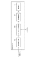
以下、本発明の第1の実施形態の詳細について図面を参照しつつ説明する。図1は、第1の実施形態における画像表示システムの構成例を示す概略図である。本実施形態に係る画像表示システムは、ユーザの頭部に装着され、眼前に仮想空間の画像を提供するHMD(画像表示装置)200と、仮想空間の画像を生成してHMD200に提供するコンピュータ装置250とを有する。また、HMD200とコンピュータ装置(画像処理装置)250とは、ケーブル240により接続されている。なお、本実施形態の画像処理システムでは、HMD200とコンピュータ装置(画像処理装置)250とがケーブル240を用いた有線の通信経路により通信する構成となっているが、代わりに無線の通信経路を用いても構わない。
[First Embodiment]
Hereinafter, the details of the first embodiment of the present invention will be described with reference to the drawings. FIG. 1 is a schematic view showing a configuration example of an image display system according to the first embodiment. The image display system according to the present embodiment is an HMD (image display device) 200 that is attached to the user's head and provides an image of the virtual space in front of the eyes, and a computer device that generates an image of the virtual space and provides the image to the HMD 200. Has 250 and. Further, the HMD 200 and the computer device (image processing device) 250 are connected by a cable 240. In the image processing system of the present embodiment, the HMD 200 and the computer device (image processing device) 250 are configured to communicate with each other by a wired communication path using a cable 240, but instead, a wireless communication path is used. It doesn't matter.
図2は、本実施形態に係る画像表示システムのブロック図である。HMD200において、MPU130は、HMD200内のメモリ131に格納されているコンピュータプログラムやデータを用いて処理を実行することで、バス190に接続されている各機能部の動作制御を行うとともに、HMD200全体の動作制御を行う。メモリ131は、MPU130に実行させるためのコンピュータプログラムやデータ、後述する画像シェーディングに係る情報等を格納する。なお、メモリ131は、MPU130が各種の処理を実行する際に用いるワークエリアを有するメモリ等も含むものである。
FIG. 2 is a block diagram of an image display system according to the present embodiment. In the HMD200, the MPU 130 controls the operation of each functional unit connected to the
位置姿勢センサ105は、検出したHMD200の位置姿勢に係る情報をコンピュータ装置250に送信する。左眼用表示ユニット100L、右眼用表示ユニット100Rは、コンピュータ装置250により生成されたCG画像に対して後述する画像処理を行なって出力される表示画像を、それぞれの表示素子1に表示する。
The position /
コンピュータ装置250では、位置姿勢算出部110が、位置姿勢センサ105で検出した位置姿勢情報に基づいてHMD200の三次元位置姿勢情報を求める。そして、CG描画部111は、算出した三次元位置姿勢情報とコンテンツDB112に格納されている仮想画像のCGコンテンツとに基づいて、左眼用と右眼用のCG画像を生成する。生成したCG画像は、HMD200に送信する。
In the
なお、コンピュータ装置250は、CPU、ROM、RAM、HDD等のハードウェア構成を備え、CPUがROMやHD等に格納されたプログラムを実行することにより、上述した各機能構成による処理が実現される。RAMは、CPUがプログラムを展開して実行するワークエリアとして機能する記憶領域を有する。ROMは、CPUが実行するプログラム等を格納する記憶領域を有する。HDDは、CPUが処理を実行する際に要する各種のプログラム、各種のデータを格納する記憶領域を有する。
The
図3に、左眼用表示ユニット100L、右眼用表示ユニット100Rの各構成を示すブロック図である。なお、左眼用表示ユニット100Lと右眼用表示ユニット100Rとは同様の構成となっている。表示画像入力部50は、コンピュータ装置250から出力された仮想空間のCG画像を取得し、取得した画像を表示用の画像信号に変換する。シェーディング補正部300は、表示用の画像信号に対して後述するシェーディング補正処理を実行し、表示駆動部51に転送する。表示駆動部51は、表示素子1を駆動して、シェーディング補正処理された表示画像を表示させる。
FIG. 3 is a block diagram showing the configurations of the left
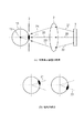
図4は、本実施形態に係る表示ユニットの光学系の構成を示す模式図である。図4(a)に示すように、本実施形態の表示ユニットは、表示素子1からの光(可視光)を射出瞳3に導く光学系2を有し、射出瞳3の位置にユーザの眼球10の瞳孔11が配置される。表示素子1は、例えば、LCDパネルや有機EL等によって構成されるものである。また、光学系2は、画像を拡大表示するための自由曲面プリズムなどによって構成されるものである。
FIG. 4 is a schematic view showing the configuration of the optical system of the display unit according to the present embodiment. As shown in FIG. 4A, the display unit of the present embodiment has an
表示素子1における画像の表示領域の中心から射出瞳3の中心に至る軸を光軸という。その光軸に沿った光線20の向きに瞳孔11を向けている状態のことを、画像中央領域を注視(または凝視)している状態という。また、表示素子1における画像左右端または画像上下端の画像周辺領域から射出瞳3の位置に至る光線21と光線22に対して、その光線の向きにそれぞれ瞳孔11を向けた状態のことを、画像周辺領域を注視(または凝視)している状態という。図4(b)に、この状態を示す。
The axis from the center of the image display area of the display element 1 to the center of the exit pupil 3 is called an optical axis. The state in which the
図5は、本実施形態に係るシェーディング補正部の構成を示すブロック図である。以下では、左眼用表示ユニット100Lにおける左眼の表示画像に対して行う処理を説明する。右眼用表示ユニット100Rにおける右眼の表示画像に対する処理は左眼の表示画像に対する処理と対称の関係であり、同様な処理のため省略する。また、本実施形態では、表示素子1にて表示する画像データはフルHD規格の水平1920、垂直1080ピクセルとするサイズとして説明する。
FIG. 5 is a block diagram showing a configuration of a shading correction unit according to the present embodiment. Hereinafter, the processing performed on the display image of the left eye in the left
画像データ入力部501は、表示画像入力部50から受けた表示用の画像信号を画素毎に処理するため、画素毎の画素値r、g、bとその画像位置情報x、yを算出し、次の処理ブロックに転送する。画像位置情報x、yは、表示画像左上を原点1、1として、画像横方向と縦方向で画素位置を指定する整数値である。また、画素値r、g、bは表示画像の赤、緑、青の輝度値のことで、通常0から255までの値域の整数値である。
In order to process the display image signal received from the display
ゲイン値算出部502は、画像位置情報x、yを受けて、表示画像に掛け合わせるゲイン値(増減係数)を算出、決定する。具体的には、ゲイン値算出部502は、バス190を介してメモリ131に保持されているシェーディング補正テーブルを参照することにより、ゲイン値を決定する。シェーディング補正テーブルは、開始点を原点として、画像位置x、yの表示画像に掛け合わせるゲイン値が指定されたデータ形式になっている。本実施形態では、シェーディング補正テーブルは全画像位置でのゲイン値が指定されたデータとして説明する。しかし、これに限らず、シェーディング補正テーブルは等間隔(または不等間隔)の格子点画像位置でのゲイン値が指定された間引きデータであってもよい。この場合、ゲイン値算出部502では画像位置x、yから近傍の格子点画像位置でのゲイン値から線形補間などして画像位置x、yでのゲイン値を算出する。メモリ131に保持されているシェーディング補正テーブルの作成方法については、後述する。
The gain
ゲイン重畳部503は、ゲイン値算出部502で決定したゲイン値を画素値r、g、bに掛け合わせる処理を行う。本実施形態では、画素値r、g、bの全てに同じゲイン値を掛け合わせる処理としているが、本発明はこれに限定されるものではない。例えば、各r、g、bで異なるシェーディング補正テーブルを用意しておくことにより、異なるゲイン値を掛け合わせる処理としてもよい。
The
画像データ出力部504は、ゲイン重畳部503から受けた画素毎の画素値r、g、bを表示用の画像信号として再合成し、次の処理ブロックである表示駆動部51へ転送する。以上の構成により、表示画像の輝度分布を補正することが可能となる。
The image
次に、本実施形態に係るシェーディング補正テーブルの作成方法について説明する。HMD200を装着したユーザは、眼球運動することで瞳孔11の向きを変え表示画像の画像中央領域から画像周辺領域にかけ画像全体を観察することが可能である。これは、図4に示したように、光軸に沿った画像中央部の光線20から画像周辺領域の光線21、22の方向に瞳孔11の向きを変化させることが可能であるということを意味し、結果的に表示画像全体を注視することが可能であること意味する。
Next, a method of creating a shading correction table according to the present embodiment will be described. A user wearing the HMD200 can change the direction of the
ここで、表示画像の画像中央領域と画像周辺領域で表示しているCGの色が同色であるならば、観察される色も同色である必要性が求められる。そのため、本実施形態で、表示画像における所望の輝度分布とは、瞳孔11の向きを変えても表示画像の輝度分布が一様で、少なくとも同色と視認できる輝度差に収まる程度の一様性であることである。そこで、本実施形態では、ユーザが表示画像全体を注視した状態で観察する所望の輝度分布を、一様な輝度分布に設計する。つまり、本実施形態では、ユーザが表示画像全体を注視した状態で観察する際の輝度分布が一様な輝度分布となるようにシェーディング補正テーブルを作成するものである。
Here, if the color of the CG displayed in the image center region and the image peripheral region of the displayed image is the same color, it is required that the observed color is also the same color. Therefore, in the present embodiment, the desired luminance distribution in the displayed image is such that the luminance distribution of the displayed image is uniform even if the direction of the
図4に示すように、HMD200を装着したユーザの眼球10の瞳孔11が射出瞳の位置3に配置されている状態において、瞳孔11を光線20、21、22に向けて画像全体を注視した場合の輝度分布の取得方法は、次のようにして行うことができる。すなわち、その取得方法は、眼球10の回転中心15に相当する位置に光軸の光線20を向いた瞳孔11を置いた時に観察される輝度分布を取得するものである。これは、光線20、21、22が略交差する焦点が眼球10の回転中心15であり、この回転中心15に相当する位置での表示画素1の像の輝度分布が画像全体を注視した場合の輝度分布に相当するからである。一般的に眼球の水平方向の直径は約23〜25mmと言われているため、本実施形態では、射出瞳の位置から眼球回転方向の向きに12mmずらした位置を眼球10の回転中心15に相当する位置とする。ただし、この距離は、一般的に眼球の水平方向の直径を考慮すると、11mmから13mmの間であれば、本実施形態の効果を奏することができる。
As shown in FIG. 4, when the
次に、眼球10の回転中心15に相当する位置での表示画素1の像の輝度分布を、測定によって取得する具体的な方法について説明する。図6は、本実施形態における輝度分布の測定方法を説明する図である。図6(a)には、輝度分布の測定に使用する撮像カメラ60を示している。撮像カメラ60は、入射瞳の位置65となる不図示の光学系とCCDイメージセンサ等の撮像素子を有する。
Next, a specific method of acquiring the luminance distribution of the image of the display pixel 1 at the position corresponding to the
図6(b)は、撮像カメラ60の入射瞳の位置65を、眼球10の回転中心15に相当する位置に配置した図である。この状態で撮影することで、光線20、21、22の画像中央領域、画像周辺領域など画像全体を注視した状態の像に相当する画像を得ることができる。ここで、測定時に光を取り込む瞳径は、標準的な明るさの表示画像を観察するとして標準的な瞳孔径4mmとした。しかし、これに限らず、明るい表示画像の場合は2mm、暗い表示画像の場合は7mmなどと、表示画像の明るさに応じて変更してもよい。
FIG. 6B is a diagram in which the
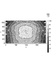
そして、この状態で得られる撮像画像の輝度分布を示したものが図7である。図7では、表示画像位置x、yにおける輝度cd/m2を等高線図で示している。輝度分布は、画像中央領域の輝度が約100cd/m2で、これに対して画像左右端領域で約175cd/m2と75%程度の輝度が増加し、画像左右上端領域で約250cd/m2と150%程度も輝度が増加する分布をしている。この輝度分布は、シェーディング補正の画像補正処理をしていない画像表示装置の素の特性である。このような輝度分布となる原因は、主に光学系2による輝度分布ムラであるものの、表示素子1の面内発光ムラや視野角特性によるものもある。なお、撮像カメラ60の持つ撮像シェーディングである輝度分布ムラは、その特性が予め調べられており、撮像シェーディング補正によって撮像カメラ60の輝度分布ムラは補正されているものとする。よって、図7に示す、取得した輝度分布には撮像カメラ60の輝度分布ムラは含まれていない。
FIG. 7 shows the brightness distribution of the captured image obtained in this state. In FIG. 7, the luminance cd / m2 at the display image positions x and y is shown in a contour diagram. As for the brightness distribution, the brightness in the central region of the image is about 100 cd / m2, whereas the brightness increases by about 75% in the left and right edge regions of the image, and about 250 cd / m2 and 150 in the upper left and right regions of the image. There is a distribution in which the brightness increases by about%. This luminance distribution is a basic characteristic of an image display device that has not undergone image correction processing for shading correction. The cause of such a brightness distribution is mainly the uneven brightness distribution due to the
次に、取得した輝度分布からシェーディング補正テーブルを作成する具体的な方法について説明する。図8は、表示画像全体を注視した状態のムラのある輝度分布から一様な輝度分布となるように、画像補正するための表示画像位置x、yにおけるシェーディング補正テーブルのゲイン値を示してある。ゲイン値は、画像中央領域での輝度を基準として全画像領域で輝度が一様となるよう各画素での輝度で逆を取る計算をするなどして、画像中央領域で約100%、画像左右端領域で約60%、画像左右上端領域で約40%と算出される。 Next, a specific method for creating a shading correction table from the acquired luminance distribution will be described. FIG. 8 shows the gain values of the shading correction table at the display image positions x and y for image correction so that the uneven brightness distribution in the state of gazing at the entire display image becomes a uniform brightness distribution. .. The gain value is approximately 100% in the center area of the image, left and right of the image, by calculating the opposite of the brightness of each pixel so that the brightness is uniform in the entire image area based on the brightness in the center area of the image. It is calculated to be about 60% in the edge region and about 40% in the left and right upper end regions of the image.
以上説明したように、本実施形態では、表示画像の全体を注視した状態で輝度分布が一様となるようにシェーディング補正テーブルを作成した。そして、このシェーディング補正テーブルを用いて表示画像の補正を行うことで、画像の中央領域と周辺領域とで輝度分布のムラを軽減することができる。 As described above, in the present embodiment, the shading correction table is created so that the brightness distribution becomes uniform while gazing at the entire displayed image. Then, by correcting the display image using this shading correction table, it is possible to reduce the unevenness of the luminance distribution between the central region and the peripheral region of the image.
[その他の実施形態]
上述の実施形態では、シェーディング補正のターゲットである表示画像の所望の輝度分布は一様な輝度分布であるとしたが、本発明は、これに限られない。すなわち、一様な輝度分布とまでは言えないまでも、例えば、表示素子1の経時的な輝度劣化が原因となる、いわゆる焼付きと言われる画像劣化を回避するために、表示素子1の中での輝度差が所定の範囲内に収まるようにすることをターゲットとしてもよい。また、表示画像の画像端で表示画画素が見える領域と見えない領域の境目である境界領域において、表示画素が見えない領域は通常真っ暗であり、見える領域の明るい画像からの輝度差が気になることがある。これを回避するため、画像周辺領域では画像境界領域である画像端にかけて徐々に輝度を弱めて行く輝度分布をターゲットとしてもよい。
[Other Embodiments]
In the above-described embodiment, the desired luminance distribution of the display image that is the target of the shading correction is a uniform luminance distribution, but the present invention is not limited to this. That is, in order to avoid image deterioration, which is so-called seizure, which is caused by the time-dependent brightness deterioration of the display element 1, for example, even if the brightness distribution is not uniform, the inside of the display element 1 The target may be such that the difference in brightness between the two is within a predetermined range. Further, in the boundary area which is the boundary between the area where the display image pixels can be seen and the area where the display image pixels cannot be seen at the image edge of the display image, the area where the display pixels cannot be seen is usually pitch black, and the difference in brightness from the bright image in the visible area is a concern. May become. In order to avoid this, in the image peripheral region, a luminance distribution in which the luminance is gradually weakened toward the image edge, which is an image boundary region, may be targeted.
また、上述の実施形態では、シェーディング補正テーブルの作成のために撮像カメラ60を使って測定した輝度分布を使用した。しかし、これに限らず、例えば光学系の光線追跡などの計算結果から、表示画像の全画像領域を注視した際の位置に瞳孔11を配置した状態での表示画素の輝度分布を取得してもよい。
Further, in the above-described embodiment, the luminance distribution measured by using the
また、上述の実施形態では、表示画像の全画像領域を注視した時の輝度分布として、射出瞳3の位置に観察の眼球10の瞳孔11を配置した際の、眼球10の回転中心位置15に相当する位置にて瞳孔11を配置して観察される輝度分布とした。しかし、眼球10の回転中心位置15が最適な位置であるものの、本発明は、これに限られない。射出瞳3の位置から所定の方向、好適には眼球10の回転中心位置15の方向にずらした位置であり、所定の距離ずらした位置15の近辺において得られる輝度分布を取得しても本発明の効果を得ることができる。
Further, in the above-described embodiment, as the brightness distribution when gazing at the entire image area of the displayed image, the
また、上述の実施形態では、一般的に眼球の水平方向の直径が約23〜25mmと言われているため、射出瞳の位置から眼球回転方向の向きに12mmずらした位置を眼球10の回転中心15に相当する位置として輝度分布を取得した。しかし、眼球の水平方向の直径には個人差があるため、複数の位置で取得した輝度分布それぞれからシェーディング補正テーブルを作成するようにしてもよい。例えば、眼球10の回転中心15に相当する位置として、射出瞳の位置から眼球回転方向の向きに11.5、12.0、12.5mmと複数ずらした位置に設定して、それぞれで輝度分布を取得する。そして、取得した各輝度分布からシェーディング補正テーブルを作成しておく。ユーザがHMDを使用する際、これらシェーディング補正テーブルそれぞれで補正された画像を実際に観察して、輝度ムラが最も発生していないと感じるものをユーザが指定し、その補正テーブルが使用されるようにしてもよい。
Further, in the above-described embodiment, since it is generally said that the horizontal diameter of the eyeball is about 23 to 25 mm, the rotation center of the
また、上述の実施形態では、標準的な瞳孔径4mmを用いて度分布を取得してシェーディング補正テーブルを作成した。しかし、表示画像の明るさによってユーザの瞳孔径は異なるため、複数の瞳孔径によりシェーディング補正テーブルを作成しておくようにしてもよい。そして、ユーザがHMDを使用する際、表示画像の明るさ(例えば、画像の全画素のr,g,bの輝度値の合計)に基づいて、シェーディング補正テーブルを選択、使用するようにしてもよい。 Further, in the above-described embodiment, a shading correction table was created by acquiring a degree distribution using a standard pupil diameter of 4 mm. However, since the pupil diameter of the user differs depending on the brightness of the displayed image, a shading correction table may be created based on a plurality of pupil diameters. Then, when the user uses the HMD, the shading correction table may be selected and used based on the brightness of the displayed image (for example, the sum of the brightness values of r, g, and b of all the pixels of the image). good.
また、上述の実施形態はVRに対応した画像表示システムの例であるが、本発明はMRに対応した画像表示システムにも適用できるものである。例えば、所謂ビデオシースルー型のHMDでは、左右両眼それぞれに対応したカメラによって現実空間を撮影し、その撮影した現実空間の画像データを画像生成装置へと送る。そして、画像生成装置は、撮影された現実空間の画像に仮想画像のCGを重畳して合成画像を生成し、その合成画像をHMDに送信する。HMDを装着したユーザは、このようにして生成された合成画像を観察することができるようになる。 Further, although the above-described embodiment is an example of an image display system compatible with VR, the present invention can also be applied to an image display system compatible with MR. For example, in a so-called video see-through type HMD, a real space is photographed by a camera corresponding to each of the left and right eyes, and the image data of the photographed real space is sent to an image generation device. Then, the image generation device superimposes the CG of the virtual image on the captured real space image to generate a composite image, and transmits the composite image to the HMD. The user wearing the HMD will be able to observe the composite image thus generated.
また、画像表示装置はHMDに限らず、表示光学系を備える画像表示装置に広く適用できるものであって、その一例としては、電子双眼鏡等が挙げられる。 Further, the image display device is not limited to the HMD, and can be widely applied to an image display device provided with a display optical system, and examples thereof include electronic binoculars and the like.
本発明は、上述の実施形態の1以上の機能を実現するプログラムを、ネットワーク又は記憶媒体を介してシステム又は装置に供給し、そのシステム又は装置のコンピュータにおける1以上のプロセッサーがプログラムを読出し実行する処理でも実現可能である。また、1以上の機能を実現する回路(例えば、ASIC)によっても実現可能である。 The present invention supplies a program that realizes one or more functions of the above-described embodiment to a system or device via a network or storage medium, and one or more processors in the computer of the system or device reads and executes the program. It can also be realized by processing. It can also be realized by a circuit (for example, ASIC) that realizes one or more functions.
1 表示素子
50 表示画像入力部
51 表示駆動部
200 HMD
300 シェーディング補正部
1
300 Shading correction unit
Claims (11)
複数の補正テーブルから選択された1つの補正テーブルを用いて、前記表示素子が表示する画像の輝度を補正する補正手段と、を有し、
前記複数の補正テーブルは、前記射出瞳の位置にユーザの眼球の瞳孔を置いた場合に、当該射出瞳の位置から前記ユーザの眼球の回転中心に相当する位置に向かう方向において、当該回転中心に相当する位置近傍の複数の位置に撮像装置の入射瞳を配置して撮像された前記表示素子の画像の複数の輝度分布に基づいて生成されることを特徴とする画像表示装置。 A display means having a display element for displaying an image and an optical system for guiding light from the display element to an exit pupil.
It has a correction means for correcting the brightness of an image displayed by the display element by using one correction table selected from a plurality of correction tables.
Wherein the plurality of correction tables, when placing the pupil of the user's eye to a position of the exit pupil, Oite in the direction from the position of the exit pupil position corresponding to the center of rotation of the eyeball of the user, the rotary An image display device, characterized in that it is generated based on a plurality of luminance distributions of an image of the display element imaged by arranging incident pupils of the image pickup device at a plurality of positions near a position corresponding to the center.
複数の補正テーブルから選択された1つの補正テーブルを用いて、前記表示素子が表示する画像の輝度を補正する補正手段と、を有し、
前記複数の補正テーブルは、前記射出瞳の位置にユーザの眼球の瞳孔を置いた場合に、当該射出瞳の位置から前記ユーザの眼球の回転中心に相当する位置に向かう方向において、当該回転中心に相当する位置に撮像装置の入射瞳を配置して、複数の異なる瞳孔径に基づいて撮像された前記表示素子の画像の複数の輝度分布に基づいて生成されることを特徴とする画像表示装置。 A display means having a display element for displaying an image and an optical system for guiding light from the display element to an exit pupil.
It has a correction means for correcting the brightness of an image displayed by the display element by using one correction table selected from a plurality of correction tables.
When the pupil of the user's eyeball is placed at the position of the exit pupil, the plurality of correction tables are set at the center of rotation in the direction from the position of the exit pupil toward the position corresponding to the center of rotation of the user's eyeball. by placing the entrance pupil of the corresponding imaging device to position an image display device characterized in that it is generated based on the plurality of luminance distribution of the image of the display device taken on the basis of a plurality of different pupil diameters.
複数の補正テーブルから選択された1つの補正テーブルを用いて、前記表示素子が表示する画像の輝度を補正する補正ステップと、を有し、
前記複数の補正テーブルは、前記射出瞳の位置にユーザの眼球の瞳孔を置いた場合に、当該射出瞳の位置から前記ユーザの眼球の回転中心に相当する位置に向かう方向において、当該回転中心に相当する位置近傍の複数の位置に撮像装置の入射瞳を配置して撮像された前記表示素子の画像の複数の輝度分布に基づいて生成されることを特徴とする画像表示方法。 A step of displaying an image by a display means having a display element for displaying an image and an optical system for guiding light from the display element to an exit pupil.
It has a correction step of correcting the brightness of an image displayed by the display element using one correction table selected from a plurality of correction tables.
Wherein the plurality of correction tables, when placing the pupil of the user's eye to a position of the exit pupil, Oite in the direction from the position of the exit pupil position corresponding to the center of rotation of the eyeball of the user, the rotary An image display method, characterized in that an image display method is generated based on a plurality of luminance distributions of an image of the display element imaged by arranging incident pupils of an image pickup device at a plurality of positions near a position corresponding to the center.
複数の補正テーブルから選択された1つの補正テーブルを用いて、前記表示素子が表示する画像の輝度を補正する補正ステップと、を有し、
前記複数の補正テーブルは、前記射出瞳の位置にユーザの眼球の瞳孔を置いた場合に、当該射出瞳の位置から前記ユーザの眼球の回転中心に相当する位置に向かう方向において、当該回転中心に相当する位置に撮像装置の入射瞳を配置して、複数の異なる瞳孔径に基づいて撮像された前記表示素子の画像の複数の輝度分布に基づいて生成されることを特徴とする画像表示方法。 A step of displaying an image by a display means having a display element for displaying an image and an optical system for guiding light from the display element to an exit pupil .
It has a correction step of correcting the brightness of an image displayed by the display element using one correction table selected from a plurality of correction tables.
When the pupil of the user's eyeball is placed at the position of the exit pupil, the plurality of correction tables are set at the center of rotation in the direction from the position of the exit pupil toward the position corresponding to the center of rotation of the user's eyeball. An image display method characterized in that the entrance pupils of an image pickup apparatus are arranged at corresponding positions and are generated based on a plurality of luminance distributions of images of the display element imaged based on a plurality of different pupil diameters.
Priority Applications (2)
| Application Number | Priority Date | Filing Date | Title |
|---|---|---|---|
| JP2017050378A JP6932526B2 (en) | 2017-03-15 | 2017-03-15 | Image display device, image display method and program |
| US15/920,330 US20180268779A1 (en) | 2017-03-15 | 2018-03-13 | Image display apparatus, image display method, and storage medium |
Applications Claiming Priority (1)
| Application Number | Priority Date | Filing Date | Title |
|---|---|---|---|
| JP2017050378A JP6932526B2 (en) | 2017-03-15 | 2017-03-15 | Image display device, image display method and program |
Publications (3)
| Publication Number | Publication Date |
|---|---|
| JP2018157276A JP2018157276A (en) | 2018-10-04 |
| JP2018157276A5 JP2018157276A5 (en) | 2020-04-16 |
| JP6932526B2 true JP6932526B2 (en) | 2021-09-08 |
Family
ID=63519502
Family Applications (1)
| Application Number | Title | Priority Date | Filing Date |
|---|---|---|---|
| JP2017050378A Active JP6932526B2 (en) | 2017-03-15 | 2017-03-15 | Image display device, image display method and program |
Country Status (2)
| Country | Link |
|---|---|
| US (1) | US20180268779A1 (en) |
| JP (1) | JP6932526B2 (en) |
Families Citing this family (2)
| Publication number | Priority date | Publication date | Assignee | Title |
|---|---|---|---|---|
| US11288503B2 (en) | 2019-11-04 | 2022-03-29 | Facebook Technologies, Llc | Systems and methods for image adjustment based on pupil size |
| WO2024159498A1 (en) * | 2023-02-02 | 2024-08-08 | Jade Bird Display (shanghai) Limited | Methods for virtual image compensation |
Family Cites Families (10)
| Publication number | Priority date | Publication date | Assignee | Title |
|---|---|---|---|---|
| JP2002016874A (en) * | 2000-04-28 | 2002-01-18 | Fuji Photo Film Co Ltd | Method and apparatus for processing image as well as recording medium for recording program therefor |
| US20070035536A1 (en) * | 2005-08-11 | 2007-02-15 | Eastman Kodak Company | Display calibration method for optimum angular performance |
| JP4779887B2 (en) * | 2006-09-01 | 2011-09-28 | ソニー株式会社 | Image display device |
| US8508449B2 (en) * | 2008-12-18 | 2013-08-13 | Sharp Corporation | Adaptive image processing method and apparatus for reduced colour shift in LCDs |
| JP5927559B2 (en) * | 2011-04-27 | 2016-06-01 | パナソニックIpマネジメント株式会社 | Display device |
| US8752963B2 (en) * | 2011-11-04 | 2014-06-17 | Microsoft Corporation | See-through display brightness control |
| DE102012205164B4 (en) * | 2012-03-29 | 2021-09-09 | Fraunhofer-Gesellschaft zur Förderung der angewandten Forschung e.V. | Projection display and method for projecting virtual images |
| US9993335B2 (en) * | 2014-01-08 | 2018-06-12 | Spy Eye, Llc | Variable resolution eye mounted displays |
| JP2017044919A (en) * | 2015-08-27 | 2017-03-02 | キヤノン株式会社 | Image display apparatus |
| KR20170070574A (en) * | 2015-12-14 | 2017-06-22 | 삼성전자주식회사 | Electronic device having flexible display and control method thereof |
-
2017
- 2017-03-15 JP JP2017050378A patent/JP6932526B2/en active Active
-
2018
- 2018-03-13 US US15/920,330 patent/US20180268779A1/en not_active Abandoned
Also Published As
| Publication number | Publication date |
|---|---|
| US20180268779A1 (en) | 2018-09-20 |
| JP2018157276A (en) | 2018-10-04 |
Similar Documents
| Publication | Publication Date | Title |
|---|---|---|
| EP3804306B1 (en) | Homography transformation matrices based temperature calibration of a viewing system | |
| US9720238B2 (en) | Method and apparatus for a dynamic “region of interest” in a display system | |
| US9595243B2 (en) | Image processing apparatus and image processing method | |
| US8629870B2 (en) | Apparatus, method, and program for displaying stereoscopic images | |
| US8456485B2 (en) | Image processing apparatus and method, head mounted display, program, and recording medium | |
| US10547832B2 (en) | Image processing apparatus, method, and storage medium for executing gradation on stereoscopic images | |
| US11366315B2 (en) | Image processing apparatus, method for controlling the same, non-transitory computer-readable storage medium, and system | |
| US20230236425A1 (en) | Image processing method, image processing apparatus, and head-mounted display | |
| WO2019217260A1 (en) | Dynamic foveated display | |
| JP6862210B2 (en) | Image processing equipment, image processing system, image processing method and program | |
| JP7365184B2 (en) | Image processing device, head-mounted display, and image display method | |
| JP6932526B2 (en) | Image display device, image display method and program | |
| JP6887824B2 (en) | Image processing equipment, image processing methods and programs | |
| US10122990B2 (en) | Imaging system and method of producing context and focus images | |
| US10771774B1 (en) | Display apparatus and method of producing images having spatially-variable angular resolutions | |
| JP2015007722A (en) | Image display device | |
| JP2017215688A (en) | Image processor and image processing method | |
| JP7429515B2 (en) | Image processing device, head-mounted display, and image display method | |
| JP5891554B2 (en) | Stereoscopic presentation device and method, blurred image generation processing device, method, and program | |
| JPH06215092A (en) | Display device | |
| JP6725999B2 (en) | Information processing apparatus, information processing apparatus control method, and program | |
| JP6622537B2 (en) | Image processing apparatus, image processing system, and image processing method | |
| CN118068572A (en) | Adjustment method, head-mounted display device, and computer medium | |
| CN118138734A (en) | Method and device for reducing dizzy feeling of display equipment, computer equipment and storage medium | |
| JP2023007716A (en) | Image display system and image display method |
Legal Events
| Date | Code | Title | Description |
|---|---|---|---|
| A521 | Request for written amendment filed |
Free format text: JAPANESE INTERMEDIATE CODE: A523 Effective date: 20200306 |
|
| A621 | Written request for application examination |
Free format text: JAPANESE INTERMEDIATE CODE: A621 Effective date: 20200306 |
|
| A977 | Report on retrieval |
Free format text: JAPANESE INTERMEDIATE CODE: A971007 Effective date: 20201215 |
|
| A131 | Notification of reasons for refusal |
Free format text: JAPANESE INTERMEDIATE CODE: A131 Effective date: 20210105 |
|
| A521 | Request for written amendment filed |
Free format text: JAPANESE INTERMEDIATE CODE: A523 Effective date: 20210305 |
|
| TRDD | Decision of grant or rejection written | ||
| A01 | Written decision to grant a patent or to grant a registration (utility model) |
Free format text: JAPANESE INTERMEDIATE CODE: A01 Effective date: 20210720 |
|
| A61 | First payment of annual fees (during grant procedure) |
Free format text: JAPANESE INTERMEDIATE CODE: A61 Effective date: 20210818 |
|
| R151 | Written notification of patent or utility model registration |
Ref document number: 6932526 Country of ref document: JP Free format text: JAPANESE INTERMEDIATE CODE: R151 |