JP6932201B2 - Optical image stabilization mechanism - Google Patents
Optical image stabilization mechanism Download PDFInfo
- Publication number
- JP6932201B2 JP6932201B2 JP2019551769A JP2019551769A JP6932201B2 JP 6932201 B2 JP6932201 B2 JP 6932201B2 JP 2019551769 A JP2019551769 A JP 2019551769A JP 2019551769 A JP2019551769 A JP 2019551769A JP 6932201 B2 JP6932201 B2 JP 6932201B2
- Authority
- JP
- Japan
- Prior art keywords
- frame
- image stabilization
- optical image
- stabilization mechanism
- shape memory
- Prior art date
- Legal status (The legal status is an assumption and is not a legal conclusion. Google has not performed a legal analysis and makes no representation as to the accuracy of the status listed.)
- Active
Links
Images


Classifications
-
- G—PHYSICS
- G02—OPTICS
- G02B—OPTICAL ELEMENTS, SYSTEMS OR APPARATUS
- G02B27/00—Optical systems or apparatus not provided for by any of the groups G02B1/00 - G02B26/00, G02B30/00
- G02B27/64—Imaging systems using optical elements for stabilisation of the lateral and angular position of the image
- G02B27/646—Imaging systems using optical elements for stabilisation of the lateral and angular position of the image compensating for small deviations, e.g. due to vibration or shake
-
- G—PHYSICS
- G03—PHOTOGRAPHY; CINEMATOGRAPHY; ANALOGOUS TECHNIQUES USING WAVES OTHER THAN OPTICAL WAVES; ELECTROGRAPHY; HOLOGRAPHY
- G03B—APPARATUS OR ARRANGEMENTS FOR TAKING PHOTOGRAPHS OR FOR PROJECTING OR VIEWING THEM; APPARATUS OR ARRANGEMENTS EMPLOYING ANALOGOUS TECHNIQUES USING WAVES OTHER THAN OPTICAL WAVES; ACCESSORIES THEREFOR
- G03B17/00—Details of cameras or camera bodies; Accessories therefor
- G03B17/02—Bodies
- G03B17/04—Bodies collapsible, foldable or extensible, e.g. book type
-
- G—PHYSICS
- G03—PHOTOGRAPHY; CINEMATOGRAPHY; ANALOGOUS TECHNIQUES USING WAVES OTHER THAN OPTICAL WAVES; ELECTROGRAPHY; HOLOGRAPHY
- G03B—APPARATUS OR ARRANGEMENTS FOR TAKING PHOTOGRAPHS OR FOR PROJECTING OR VIEWING THEM; APPARATUS OR ARRANGEMENTS EMPLOYING ANALOGOUS TECHNIQUES USING WAVES OTHER THAN OPTICAL WAVES; ACCESSORIES THEREFOR
- G03B5/00—Adjustment of optical system relative to image or object surface other than for focusing
- G03B5/02—Lateral adjustment of lens
-
- G—PHYSICS
- G03—PHOTOGRAPHY; CINEMATOGRAPHY; ANALOGOUS TECHNIQUES USING WAVES OTHER THAN OPTICAL WAVES; ELECTROGRAPHY; HOLOGRAPHY
- G03B—APPARATUS OR ARRANGEMENTS FOR TAKING PHOTOGRAPHS OR FOR PROJECTING OR VIEWING THEM; APPARATUS OR ARRANGEMENTS EMPLOYING ANALOGOUS TECHNIQUES USING WAVES OTHER THAN OPTICAL WAVES; ACCESSORIES THEREFOR
- G03B2205/00—Adjustment of optical system relative to image or object surface other than for focusing
- G03B2205/0007—Movement of one or more optical elements for control of motion blur
- G03B2205/0015—Movement of one or more optical elements for control of motion blur by displacing one or more optical elements normal to the optical axis
-
- G—PHYSICS
- G03—PHOTOGRAPHY; CINEMATOGRAPHY; ANALOGOUS TECHNIQUES USING WAVES OTHER THAN OPTICAL WAVES; ELECTROGRAPHY; HOLOGRAPHY
- G03B—APPARATUS OR ARRANGEMENTS FOR TAKING PHOTOGRAPHS OR FOR PROJECTING OR VIEWING THEM; APPARATUS OR ARRANGEMENTS EMPLOYING ANALOGOUS TECHNIQUES USING WAVES OTHER THAN OPTICAL WAVES; ACCESSORIES THEREFOR
- G03B2205/00—Adjustment of optical system relative to image or object surface other than for focusing
- G03B2205/0053—Driving means for the movement of one or more optical element
- G03B2205/0076—Driving means for the movement of one or more optical element using shape memory alloys
Description
形状記憶合金(SMA)ワイヤに基づくアクチュエータは、この技術に関連する固有の利点に起因して、ますます採用されており、特に、マイクロモーターに代わるそれらアクチュエータの能力は、負担、信頼性、電力消費の観点から利点をもたらす。 Actuators based on shape memory alloy (SMA) wire are increasingly being adopted due to the inherent advantages associated with this technology, especially the ability of those actuators to replace micromotors in terms of burden, reliability and power. It brings advantages in terms of consumption.
これらアクチュエータを使用することは、とりわけ携帯電話の用途のための光学式手ブレ補正機構(OIS)において、小型化への要求が高まりかつ電力消費を最小限にする必要があるため特に高く評価されている。 The use of these actuators is particularly appreciated due to the increasing demand for miniaturization and the need to minimize power consumption, especially in optical image stabilization (OIS) for mobile phone applications. ing.
SMAワイヤを使用して光学システムにおける画像安定性を制御するための初期の技術的解決法のいくつかは、特許文献1および特許文献2に記載される解決法などのように傾斜に基づいていた。 Some of the early technical solutions for controlling image stability in optical systems using SMA wires were based on tilt, such as the solutions described in Patent Documents 1 and 2. ..
傾斜を用いた解決法の主な欠点は、特許文献3の段落番号[0026]〜[0028]に記載されており、手短に言うと、可動画像センサからカメラの固定構造への電気接続の経路決定が困難であることと、OISカメラの高さおよび設置面積をOISのない同等のカメラよりも大きくせざるを得ないことと、に関連する。 The main drawbacks of the tilt solution are described in paragraphs [0026]-[0028] of Patent Document 3, and in short, the path of electrical connection from the movable image sensor to the fixed structure of the camera. It is related to the difficulty of determining and the fact that the height and footprint of the OIS camera must be larger than that of an equivalent camera without OIS.
これら欠点は、SMAアクチュエータワイヤがOISの主軸に対して略垂直に配置される非傾斜(シフト/並進)システムの開発を引き起こし、それによって、それらシステムは前記軸に垂直な小さな広がりを有し、したがってシステムの高さが最小化された。そうしたシステムにおけるSMAワイヤの使用に関連する問題の1つが、トルク力であり、当該トルク力は、可動要素をその主軸の周りで回転させる傾向を引き起こすことによってシステムの出力性能に影響を及ぼすことがあり、あるいはその構造に付加的な応力をもたらすことがあり、当該付加的な応力は、早すぎる経年劣化をもたらし、結果として、時間の経過とともに性能を低下させ、場合によっては早すぎる故障につながることがある。特許文献3では、この問題は、トルク力成分を打ち消すような方法で位置決めされた非共線ワイヤを用いて解決される。 These drawbacks have led to the development of non-tilted (shift / translation) systems in which the SMA actuator wires are located approximately perpendicular to the main axis of the OIS, thereby causing them to have a small spread perpendicular to the axis. Therefore, the height of the system was minimized. One of the problems associated with the use of SMA wires in such systems is torque force, which can affect the output performance of the system by causing a tendency to rotate the moving element around its spindle. Yes, or it may introduce additional stress to its structure, which results in premature aging, resulting in poor performance over time and in some cases premature failure. Sometimes. In Patent Document 3, this problem is solved by using a non-collinear wire positioned in such a way as to cancel the torque force component.
OISシステムにSMAワイヤを組み込んで使用するための別の手法が、出願人の名前における特許文献4に記載されており、当該文献は、SMAワイヤの作用下で変形される弾性構造ケージを備えるOIS用途に適した弾性構造を使用することを開示する。OIS構造フレームの変形を示す異なる解決法が、特許文献5にさらに開示されている。 Another technique for incorporating and using SMA wire in an OIS system is described in Patent Document 4 in the name of the applicant, which document is an OIS with an elastic cage that is deformed under the action of SMA wire. Disclose that the elastic structure suitable for the application is used. A different solution showing the deformation of the OIS structural frame is further disclosed in Patent Document 5.
本発明の目的は、特許文献4に開示されているものとは異なり、傾斜およびトルク力成分の管理に関連する問題に悩まされないOISシステムのための剛性構造を提供することであり、その第1の態様において、3つの積層フレームすなわち下部フレームと中間フレームと上部フレームとを備える光学式手ブレ補正機構で構成され、当該上部フレームは、1つ以上の撮像システムをしっかりと保持するのに適しており、各積層フレームは、少なくとも4つの可撓性接続要素を用いて少なくとも別のフレームに接続されており、中間フレームおよび上部フレームは、下部フレームに対して摺動可能であり、中間フレームおよび上部フレームの動作は、互いに対してかつ(1つ以上の)撮像システムの光軸に対して直交しており、こうした直交する動作の各々は、一組の打消(antagonistic)形状記憶合金ワイヤによって制御される。 An object of the present invention is to provide a rigid structure for an OIS system that does not suffer from problems related to tilt and torque component management, unlike those disclosed in Patent Document 4. In the above aspect, the upper frame is composed of an optical camera shake correction mechanism including three laminated frames, that is, a lower frame, an intermediate frame, and an upper frame, and the upper frame is suitable for firmly holding one or more imaging systems. Each laminated frame is connected to at least another frame using at least four flexible connecting elements, the intermediate and upper frames are slidable with respect to the lower frame, and the intermediate and upper frames are slidable. The movements of the frames are orthogonal to each other and to the optical axis of the imaging system (one or more), and each of these orthogonal movements is controlled by a set of antagonistic shape memory alloy wires. NS.
以下の図面を用いて本発明についてさらに説明する。 The present invention will be further described with reference to the following drawings.
上述の図面において、寸法および寸法の比率は、正確でないことがあり、なお場合によって図面の読みやすさを向上させるために変更されている;また、本発明の理解に必須ではない要素、例えばSMAワイヤの接続部および固定部は、補助的なものでありかつ当該技術分野で公知となっているため、通常は図示されない。 In the drawings described above, the dimensions and the ratio of dimensions may not be accurate and may be modified to improve the readability of the drawings; also elements that are not essential to the understanding of the present invention, such as SMA. Wire connections and fixations are not usually shown because they are ancillary and well known in the art.
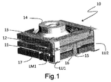
図1は、本発明に基づく光学式手ブレ補正機構(OIS)を備えるカメラモジュール10の斜視図を示す。カメラモジュール10の撮像システム14は、垂直に積層された下部フレーム11と中間フレーム12と上部フレーム13とを備えるOIS上にしっかりと固定されている。下部フレーム11および上部フレーム13は、4つの可撓性接続要素LU(下部−上部)を用いて接続されており、斜視図には2つの可撓性接続要素LU1およびLU2のみが示されており、一方で下部フレーム11および中間フレーム12は、4つの可撓性接続要素LM(下部−中間)を用いて接続されており、斜視図には1つの可撓性接続要素LM1のみが示されている。この実施形態では、中間フレーム12は、反対側の側面に配置される2つの下方突出部15、15’を有しており、斜視図では1つの下方突出部15のみが見られる。各突出部15、15’は、下部フレーム11に形成された適切な凹部を通過して、OISの底部まで下方に延在する。
FIG. 1 shows a perspective view of a
撮像システム14の光軸に直交するこれらフレームの相互的かつ純粋な並進動作は、弓形またはV字形の構成における二組の打消SMAワイヤ16、16’および17、17’によって提供され、斜視図には各組の1つの要素16、17のみが斜視図で示されている。
The reciprocal and pure translational motion of these frames orthogonal to the optical axis of the
特にワイヤ16、16’の先端部は下部フレーム11に固定され、ワイヤ16、16’は、ワイヤ16、16’の中央部分と係合するために保持要素として溝を有する下方突出部15、15’を介して中間フレーム12に作用する。同様に、ワイヤ17、17’の先端部は中間フレーム12に固定され、それらワイヤ17、17’の中央部分は、保持要素(図示せず)として上部フレーム13と一体化された下方突出フック18、18’を介して上部フレーム13に作用する(この図では見えない)。弓形またはV字形の構成におけるSMAワイヤ16、16’および17、17’は、中央部分保持要素(つまりこの実施形態では溝およびフック)から等しく離れた点に接続される先端部を有するのが便利である。
In particular, the tips of the
垂直積層フレームを接続する可撓性接続要素LU、LMは、フレームを適所に保つ機能と、それらフレームが活性化された(加熱された)SMAワイヤによって引っ張られた場合にそれらフレームの並進動作を可能にする機能と、の両方を有する。 The flexible connecting elements LU, LM that connect the vertically laminated frames provide the ability to keep the frames in place and the translational behavior of those frames when pulled by activated (heated) SMA wires. It has both a function that enables it and a function that enables it.
図2は、2つの撮像システム24、24’を備えるカメラモジュール20の斜視図を示し、この図は、デュアルカメラ携帯電話に使用され得るカメラモジュールを表す。図1に対して、図2は、4つの可撓性接続要素LUのうちすべての可撓性接続要素LU1、LU2、LU3、LU4と、4つの可撓性接続要素LMのうち2つの可撓性接続要素LM1、LM2の認識および注目を可能にする。
FIG. 2 shows a perspective view of a
本発明は原則として設置される撮像システムの数に限定されないが、最も有用な構成は、1つまたは2つの撮像システムの使用を想定する。好ましい実施形態では、カメラモジュールに取り付けられた撮像システムは、カメラモジュール内に埋め込まれたそれら自体のオートフォーカス機能を有しており、そうしたオートフォーカス機能は、OIS制御機能とは独立して制御され、一方でOIS機能は、本発明によって実現されて制御される。 The present invention is not limited to the number of imaging systems installed in principle, but the most useful configuration assumes the use of one or two imaging systems. In a preferred embodiment, the imaging system mounted on the camera module has its own autofocus function embedded within the camera module, such autofocus function being controlled independently of the OIS control function. On the other hand, the OIS function is realized and controlled by the present invention.
一般的に言えば、可撓性接続要素は、図1に示されるように、可撓性接続要素の幅wおよび厚さtによって幾何学的に特徴付けられる。可撓性接続要素の長さは、主に、可撓性接続要素が接続するフレーム間の垂直方向の広がりに、短い水平方向の端部を加えて、決定される。そのため可撓性接続要素LUは、可撓性接続要素LMよりも長くなるが、それは、可撓性接続要素LMが隣接するフレームを接続するのに対して可撓性接続要素LUが下部フレームと上部フレームとを接続するからである。 Generally speaking, the flexible connecting element is geometrically characterized by the width w and thickness t of the flexible connecting element, as shown in FIG. The length of the flexible connecting element is primarily determined by adding a short horizontal end to the vertical spread between the frames to which the flexible connecting element connects. Therefore, the flexible connecting element LU is longer than the flexible connecting element LM, which is because the flexible connecting element LM connects adjacent frames, whereas the flexible connecting element LU connects with the lower frame. This is because it connects to the upper frame.
好ましくは、可撓性接続要素の厚さtは0.05〜0.15mmに含まれ、一方でその幅wは0.3〜0.5mmに含まれる。結果として、可撓性接続要素(LU、LM)は、10:1から2:1、最も好ましくは約4:1の幅/厚さ比(w/t)を有する。 Preferably, the thickness t of the flexible connecting element is included in 0.05-0.15 mm, while its width w is included in 0.3-0.5 mm. As a result, the flexible connecting elements (LU, LM) have a width / thickness ratio (w / t) of 10: 1 to 2: 1, most preferably about 4: 1.
図1および図2に示す好ましい実施形態では、下部フレームおよび上部フレームの4つの対応する角を接続する4つの可撓性接続要素LUが設けられており、当該可撓性接続要素が配置されるフレーム側面はLU側面として定義され、一方で、下部フレームおよび中間フレームは、下部フレームおよび中間フレームの対応する部分を接続する4つの可撓性接続要素LMを用いて接続され、当該可撓性接続要素LMが配置されるフレーム側面はLM側面として定義され、LM側面は好ましくはLU側面に隣接する(これは、好ましくは可撓性接続要素LUと可撓性接続要素LMとが同じフレーム側面上にないことを意味する)。 In the preferred embodiment shown in FIGS. 1 and 2, four flexible connecting elements LU connecting the four corresponding corners of the lower frame and the upper frame are provided and the flexible connecting elements are arranged. The side of the frame is defined as the LU side, while the lower and intermediate frames are connected using four flexible connecting elements LM that connect the corresponding parts of the lower and intermediate frames, said flexible connection. The side of the frame on which the element LM is located is defined as the LM side, which is preferably adjacent to the LU side (which is preferably on the same frame side where the flexible connecting element LU and the flexible connecting element LM are located). Means not in).
図1および図2は、本発明に基づく特定の非限定的な実施形態を示していることを強調すべきであり、例えば付加的な可撓性接続要素がフレーム側面に沿って配置されてもよく;そうした付加的な可撓性接続要素を使用することは、図2におけるように、2つの別々の隣接する撮像システムを収容するのに必要なより大きなシステム長を考慮すると、ダブルカメラシステムの場合に好ましい。別の変形例は、下方突出部15、15’の代わりに、中間フレーム12からの上方突出部15、15’を包含してもよい。
It should be emphasized that FIGS. 1 and 2 show certain non-limiting embodiments based on the present invention, even if additional flexible connecting elements are arranged along the sides of the frame, for example. Well; the use of such additional flexible connecting elements is of a double camera system, given the larger system length required to accommodate two separate adjacent imaging systems, as in FIG. Preferred in some cases. Another modification may include
カメラモジュール10の図3A、図3Bの断面図は、打消SMAワイヤ組16−16’、17−17’の位置決めを示す。ワイヤ組16−16’の分離および相互位置決めは、図3Aの正面図(明瞭化のために撮像システム14は省略されている)および図3Bの平面図の両方において見ることができる一方で、打消ワイヤ組17−17’の相互位置決めは図3Bにおいてのみ見ることができる。
The cross-sectional views of FIGS. 3A and 3B of the
中間フレーム12から下方に延在する突出部15、15’は、SMAワイヤ16、16’によって係合され、その一方で、上部フレーム13に形成された係留要素18、18’は、ワイヤ17、17’によって係合され、OIS積層フレームの並進動作を介した撮像システム14のポジション制御が可能となる。
The
このように、本発明に基づくOISシステムは、図1、図2、図3Aおよび図3Bに例示されており、OIS自体の理解および働きを改善するためだけに、これらの図面には撮像システム14、24、24’の存在が追加されている。
As described above, the OIS system based on the present invention is illustrated in FIGS. 1, 2, 3A and 3B, and the
好ましい実施形態では、可撓性接続要素はまた、SMAワイヤの先端部のための係留点であり、かつSMAワイヤを作動させるために電流を供給できるように屈曲可能な導電性材料から作られる。したがって、可撓性接続要素は本質的に、SMAワイヤに作動電流を供給するために、屈曲可能な金属、または金属片などの導電性要素を備える屈曲可能なプラスチックで作られる。 In a preferred embodiment, the flexible connecting element is also made of a bendable conductive material that is a mooring point for the tip of the SMA wire and is capable of supplying an electric current to actuate the SMA wire. Therefore, the flexible connecting element is essentially made of flexible metal, or flexible plastic with a conductive element such as a piece of metal, to supply the working current to the SMA wire.
可撓性/屈曲可能との用語は、破断することなく多数の変形サイクルを受けることができる能力を有する材料を意図しており、この理由から、好ましくは、1〜100GPaの範囲のヤング率を有する材料が使用される。 The term flexible / flexible is intended for materials capable of undergoing multiple deformation cycles without breaking, and for this reason Young's modulus in the range of 1-100 GPa is preferred. The material to have is used.
図示される実施形態では、下部フレーム11または上部フレーム13は、中間フレームの各突出部15、15’の終端部分に対応して、SMAワイヤ16、16’の先端部のための2つの接続点を有しており、そうした接続点は突出部15、15’の中央から同じ距離にある。図1および図2の斜視図では、突出部15、15’は、中間フレーム12から下方に延在しており、そのためSMAワイヤの先端部の接続点を有するのは下部フレーム11となる。
In the illustrated embodiment, the
別の実施形態では、中間フレーム12は、下方または上方突出部15、15’を有する側面に隣接する側面において、2つの打消SMAワイヤ17、17’のための2つの接続点を有しており、その一方で、SMAワイヤ中央部分は、異なるフレーム、すなわち突出方向と反対側のフレームに係合される。図1および図2の斜視図では、突出部15は下方に延在しており、そのため中間フレーム12と上部フレーム13とを接続するSMAワイヤ17、17’は、フック18、18’(図3B)などの適切な保持要素を用いて上部フレーム13に係合される中央部分を有する。
In another embodiment, the
本発明に基づくOISに使用されるSMAワイヤは、特定のタイプに限定されず、ジュール効果によって活性化される任意のSMAワイヤが有用に使用されてもよい。それでもやはり、ニチノールの名称で当該分野で公知であり、10μm〜50μmの範囲の直径を有し、かつ様々な供給元から市販されているNi−Ti合金で作られたSMAワイヤを使用することが好ましく、例えば当該ワイヤは、SAES Getters SpAによってSmartflexの商品名で販売されており、特に25μmのワイヤを使用することが優先される。 The SMA wire used in the OIS based on the present invention is not limited to a specific type, and any SMA wire activated by the Joule effect may be usefully used. Nevertheless, it is possible to use SMA wires made of Ni-Ti alloys known in the art under the name Nitinol, having diameters in the range of 10 μm to 50 μm and commercially available from various sources. Preferably, for example, the wire is sold by SAES Getters SpA under the trade name of Smartflex, with particular preference given to the use of 25 μm wire.
打消ワイヤを稼働させかつ制御する方法に関して、この情報は当業者に公知であり、例えば2012年にSensors、第12号、p.7682-7700で公開されたWang、他著による文書「自己検知を伴う正確に制御された打消形状記憶合金アクチュエータ(An accurately controlled antagonistic shape memory alloy actuator with self-sensing)」を参照されたい。 This information is known to those of skill in the art regarding how to operate and control the counteracting wire, for example, the document "Self-Detection" by Wang, published in Sensors, No. 12, p.7682-7700 in 2012. See An accurately controlled antagonistic shape memory alloy actuator with self-sensing.
10 カメラモジュール
11 下部フレーム
12 中間フレーム
13 上部フレーム
14;24、24’ 撮像システム
15、15’ 突出部
16、16’;17、17’ 形状記憶合金ワイヤ
18、18’ 保持要素
20 カメラモジュール
10
Claims (9)
前記上部フレーム(13)は、1つ以上の撮像システム(14;24、24’)を安定して保持するのに適しており、
前記積層フレームそれぞれは、少なくとも4つの可撓性要素(LM、LU)を用いて少なくとも別の積層フレームに接続され、前記中間フレーム(12)および前記上部フレーム(13)は、前記下部フレーム(11)に対して摺動可能であり、
前記中間フレーム(12)および前記上部フレーム(13)の動作は、互いに対してかつ前記撮像システムの光軸に対して直交しており、
3つの前記積層フレームのうち2つの前記積層フレームの組み合わせに関して、一方の前記積層フレームのうち前記光軸に対して直交する第1方向における反対側の2つの側面には、それぞれ形状記憶合金ワイヤ(16、16’)が接続され、他方の前記積層フレームは、前記形状記憶合金ワイヤ(16、16’)とそれぞれ係合する垂直突出部(15、15’)を有し、
3つの前記積層フレームのうち前記組み合わせとは異なる2つの前記積層フレームの組み合わせに関して、一方の前記積層フレームののうち前記光軸および前記第1方向の双方と直交する第2方向における反対側の2つの側面には、それぞれ形状記憶合金ワイヤ(17、17’)が接続され、他方の前記積層フレームは、前記形状記憶合金ワイヤ(17、17’)とそれぞれ係合する係留要素(18、18’)を有することを特徴とする光学式手ブレ補正機構。 An optical image stabilization mechanism including three laminated frames, that is, a lower frame (11), an intermediate frame (12), and an upper frame (13).
The upper frame (13) is suitable for stably holding one or more imaging systems (14; 24, 24').
The laminated frames, respectively, are connected to at least another of the stacked frame using at least four flexible elements (LM, LU), said intermediate frame (12) and said upper frame (13), said lower frame (11 ) Is slidable,
The operations of the intermediate frame (12) and the upper frame (13) are orthogonal to each other and to the optical axis of the imaging system.
Regarding the combination of the two laminated frames of the three laminated frames, the shape memory alloy wires (respectively) on the two side surfaces of one of the laminated frames on the opposite side in the first direction orthogonal to the optical axis 16, 16') are connected, and the other laminated frame has vertical protrusions (15, 15') that engage with the shape memory alloy wire (16, 16'), respectively.
With respect to a combination of two laminated frames different from the combination of the three laminated frames, two of the laminated frames on the opposite side in the second direction orthogonal to both the optical axis and the first direction. Shape memory alloy wires (17, 17') are connected to each of the side surfaces, and the other laminated frame has mooring elements (18, 18') that engage with the shape memory alloy wires (17, 17'), respectively. optical image stabilization mechanism, characterized in that have a).
前記垂直突出部(15、15’)の各々の終端部分において、前記形状記憶合金ワイヤ(16、16’)の中央部分と係合するのに適した保持要素を備えていることを特徴とする請求項1に記載の光学式手ブレ補正機構。 Said intermediate frame (12), in the two opposite sides in the first direction, two of said vertical protruding portion (15, 15 ') has one on each side of the opposite ,
At each end of the vertical protrusion (15, 15'), a holding element suitable for engaging with the central portion of the shape memory alloy wire (16, 16') is provided. The optical image stabilization mechanism according to claim 1.
前記可撓性要素(LU)は、前記下部フレーム(11)および前記上部フレーム(13)の2つの反対側の側面において対をなして配置されていることを特徴とする請求項1に記載の光学式手ブレ補正機構。 The four flexible elements (LU) connect the four corners of the lower frame (11) and the upper frame (13).
The first aspect of the present invention, wherein the flexible elements (LU) are arranged in pairs on two opposite side surfaces of the lower frame (11) and the upper frame (13). Optical image stabilization mechanism.
Applications Claiming Priority (3)
| Application Number | Priority Date | Filing Date | Title |
|---|---|---|---|
| IT102016000125596A IT201600125596A1 (en) | 2016-12-13 | 2016-12-13 | Optical image stabilizer |
| IT102016000125596 | 2016-12-13 | ||
| PCT/IB2017/057839 WO2018109659A1 (en) | 2016-12-13 | 2017-12-12 | Optical image stabilizer |
Publications (3)
| Publication Number | Publication Date |
|---|---|
| JP2020502591A JP2020502591A (en) | 2020-01-23 |
| JP2020502591A5 JP2020502591A5 (en) | 2021-01-21 |
| JP6932201B2 true JP6932201B2 (en) | 2021-09-08 |
Family
ID=58347851
Family Applications (1)
| Application Number | Title | Priority Date | Filing Date |
|---|---|---|---|
| JP2019551769A Active JP6932201B2 (en) | 2016-12-13 | 2017-12-12 | Optical image stabilization mechanism |
Country Status (8)
| Country | Link |
|---|---|
| US (1) | US10514593B2 (en) |
| EP (1) | EP3497517B1 (en) |
| JP (1) | JP6932201B2 (en) |
| KR (1) | KR102258952B1 (en) |
| CN (1) | CN110023831B (en) |
| IT (1) | IT201600125596A1 (en) |
| TW (1) | TWI723239B (en) |
| WO (1) | WO2018109659A1 (en) |
Families Citing this family (7)
| Publication number | Priority date | Publication date | Assignee | Title |
|---|---|---|---|---|
| KR102125086B1 (en) * | 2018-08-28 | 2020-06-19 | 삼성전기주식회사 | Camera module |
| KR20200055317A (en) * | 2018-11-13 | 2020-05-21 | 삼성전기주식회사 | Actuator Of Camera module |
| KR102609149B1 (en) * | 2018-10-15 | 2023-12-05 | 삼성전기주식회사 | Method of Manufacturing For Camera module |
| WO2020243860A1 (en) * | 2019-06-01 | 2020-12-10 | 瑞声光学解决方案私人有限公司 | Optical anti-vibration lens assembly and optical anti-vibration method therefor |
| CN211554446U (en) * | 2020-08-19 | 2020-09-22 | 瑞声通讯科技(常州)有限公司 | Lens module |
| KR102439902B1 (en) | 2020-09-25 | 2022-09-05 | 삼성전기주식회사 | Camera module |
| KR20240046548A (en) | 2021-08-13 | 2024-04-09 | 액추에이터 솔루션스 게엠베하 | Actuator subassembly controlled by shape memory alloy wire, system comprising a plurality of such subassemblies, and method of controlling such system |
Family Cites Families (19)
| Publication number | Priority date | Publication date | Assignee | Title |
|---|---|---|---|---|
| JP3783410B2 (en) | 1998-05-28 | 2006-06-07 | コニカミノルタフォトイメージング株式会社 | Correction optical device |
| JP4857550B2 (en) * | 2004-12-06 | 2012-01-18 | コニカミノルタホールディングス株式会社 | Drive device and drive system |
| US7656460B2 (en) * | 2007-08-21 | 2010-02-02 | Sony Ericsson Mobile Communications Ab | Autofocus assembly that adjusts a lens in the optical axis direction by alignment of holes in a spacing ring that receive ball bearings |
| JP4935641B2 (en) * | 2007-11-19 | 2012-05-23 | コニカミノルタオプト株式会社 | Drive device using shape memory alloy |
| JP5458101B2 (en) * | 2008-09-12 | 2014-04-02 | ケンブリッジ メカトロニクス リミテッド | Optical image stabilization |
| US8830335B2 (en) * | 2010-02-26 | 2014-09-09 | Cambridge Mechatronics Limited | SMA actuation apparatus |
| TWI416240B (en) * | 2011-03-30 | 2013-11-21 | Largan Precision Co Ltd | Photographing module |
| WO2012153600A1 (en) * | 2011-05-09 | 2012-11-15 | コニカミノルタアドバンストレイヤー株式会社 | Lens-driving device and image pick-up device |
| KR101354775B1 (en) * | 2011-12-23 | 2014-01-22 | 삼성전기주식회사 | Camera module |
| JPWO2013118601A1 (en) * | 2012-02-07 | 2015-05-11 | コニカミノルタ株式会社 | Driving device and lens unit |
| WO2013175197A1 (en) | 2012-05-25 | 2013-11-28 | Cambridge Mechatronics Limited | Shape memory alloy actuation apparatus |
| JP2014126668A (en) * | 2012-12-26 | 2014-07-07 | Mitsumi Electric Co Ltd | Lens drive device, camera module and portable terminal with camera |
| KR102187571B1 (en) * | 2014-08-11 | 2020-12-07 | 엘지전자 주식회사 | Mobile terminal |
| CN204576031U (en) * | 2015-01-30 | 2015-08-19 | 思考电机(上海)有限公司 | Optical image stablizes camera lens module |
| KR102272706B1 (en) * | 2015-05-05 | 2021-07-05 | 액추에이터 솔루션스 게엠베하 | Tilt module subassembly and optical image stabilizer including same |
| GB201508968D0 (en) * | 2015-05-26 | 2015-07-01 | Cambridge Mechatronics Ltd | SMA wire assembly |
| CN108351487B (en) * | 2015-11-03 | 2021-08-17 | Lg伊诺特有限公司 | Lens driving device, camera module, and optical device |
| CN107277305B (en) * | 2016-04-01 | 2020-10-09 | 台湾东电化股份有限公司 | Camera module and control method thereof |
| JP6743554B2 (en) * | 2016-07-29 | 2020-08-19 | Tdk株式会社 | Lens drive |
-
2016
- 2016-12-13 IT IT102016000125596A patent/IT201600125596A1/en unknown
-
2017
- 2017-12-11 TW TW106143356A patent/TWI723239B/en active
- 2017-12-12 JP JP2019551769A patent/JP6932201B2/en active Active
- 2017-12-12 EP EP17817903.2A patent/EP3497517B1/en active Active
- 2017-12-12 WO PCT/IB2017/057839 patent/WO2018109659A1/en active Search and Examination
- 2017-12-12 US US16/336,402 patent/US10514593B2/en active Active
- 2017-12-12 CN CN201780071700.1A patent/CN110023831B/en active Active
- 2017-12-12 KR KR1020197016506A patent/KR102258952B1/en active IP Right Grant
Also Published As
| Publication number | Publication date |
|---|---|
| EP3497517B1 (en) | 2020-03-04 |
| US10514593B2 (en) | 2019-12-24 |
| CN110023831B (en) | 2022-07-08 |
| IT201600125596A1 (en) | 2018-06-13 |
| WO2018109659A1 (en) | 2018-06-21 |
| JP2020502591A (en) | 2020-01-23 |
| TWI723239B (en) | 2021-04-01 |
| EP3497517A1 (en) | 2019-06-19 |
| KR102258952B1 (en) | 2021-06-02 |
| TW201827913A (en) | 2018-08-01 |
| KR20190094362A (en) | 2019-08-13 |
| CN110023831A (en) | 2019-07-16 |
| US20190243216A1 (en) | 2019-08-08 |
Similar Documents
| Publication | Publication Date | Title |
|---|---|---|
| JP6932201B2 (en) | Optical image stabilization mechanism | |
| JP6619444B2 (en) | Tilt module subassembly and optical image stabilization mechanism including the tilt module subassembly | |
| KR102265355B1 (en) | Driving device, camera device and electronic apparatus | |
| CN104956254B (en) | For the suspension of camera lens element | |
| US9753300B2 (en) | Shape memory alloy actuation apparatus | |
| CN104335101B (en) | shape memory alloy actuation apparatus | |
| JP4366197B2 (en) | Stage device and camera shake correction device using the stage device | |
| US20130002933A1 (en) | Sma actuation apparatus | |
| TW201115205A (en) | Wafer level optical system | |
| EP3210078A1 (en) | Camera module autofocus actuator and control method thereof | |
| US20140092493A1 (en) | Piezoelectric and mems actuator | |
| JP6271720B2 (en) | Camera module and camera module manufacturing method | |
| JP2005250400A (en) | Stage device and camera shake correction unit using stage device | |
| TW201435466A (en) | Auto-focus device with shape memory actuator | |
| TW200946953A (en) | Optical lens image stabilization systems | |
| KR102294805B1 (en) | Lens driving device, camera device and electronic apparatus | |
| CN210986190U (en) | Liquid lens focusing and anti-shake mechanism, camera module and electronic equipment | |
| JP2008178285A (en) | Piezoelectric actuator and electronic device using the same | |
| JP2013097346A (en) | Drive unit | |
| JPWO2015005216A1 (en) | Lens displacement device | |
| JP2010273456A (en) | Drive unit and imaging device |
Legal Events
| Date | Code | Title | Description |
|---|---|---|---|
| A521 | Request for written amendment filed |
Free format text: JAPANESE INTERMEDIATE CODE: A523 Effective date: 20190814 |
|
| A521 | Request for written amendment filed |
Free format text: JAPANESE INTERMEDIATE CODE: A523 Effective date: 20201130 |
|
| A621 | Written request for application examination |
Free format text: JAPANESE INTERMEDIATE CODE: A621 Effective date: 20201130 |
|
| A871 | Explanation of circumstances concerning accelerated examination |
Free format text: JAPANESE INTERMEDIATE CODE: A871 Effective date: 20201130 |
|
| A975 | Report on accelerated examination |
Free format text: JAPANESE INTERMEDIATE CODE: A971005 Effective date: 20210224 |
|
| A131 | Notification of reasons for refusal |
Free format text: JAPANESE INTERMEDIATE CODE: A131 Effective date: 20210308 |
|
| A521 | Request for written amendment filed |
Free format text: JAPANESE INTERMEDIATE CODE: A523 Effective date: 20210604 |
|
| TRDD | Decision of grant or rejection written | ||
| A01 | Written decision to grant a patent or to grant a registration (utility model) |
Free format text: JAPANESE INTERMEDIATE CODE: A01 Effective date: 20210719 |
|
| A61 | First payment of annual fees (during grant procedure) |
Free format text: JAPANESE INTERMEDIATE CODE: A61 Effective date: 20210817 |
|
| R150 | Certificate of patent or registration of utility model |
Ref document number: 6932201 Country of ref document: JP Free format text: JAPANESE INTERMEDIATE CODE: R150 |