JP6932134B2 - Closure device that detachably connects two parts - Google Patents
Closure device that detachably connects two parts Download PDFInfo
- Publication number
- JP6932134B2 JP6932134B2 JP2018538227A JP2018538227A JP6932134B2 JP 6932134 B2 JP6932134 B2 JP 6932134B2 JP 2018538227 A JP2018538227 A JP 2018538227A JP 2018538227 A JP2018538227 A JP 2018538227A JP 6932134 B2 JP6932134 B2 JP 6932134B2
- Authority
- JP
- Japan
- Prior art keywords
- closure
- magnet
- closure device
- shape coupling
- portions
- Prior art date
- Legal status (The legal status is an assumption and is not a legal conclusion. Google has not performed a legal analysis and makes no representation as to the accuracy of the status listed.)
- Active
Links
Images


Classifications
-
- A—HUMAN NECESSITIES
- A44—HABERDASHERY; JEWELLERY
- A44B—BUTTONS, PINS, BUCKLES, SLIDE FASTENERS, OR THE LIKE
- A44B11/00—Buckles; Similar fasteners for interconnecting straps or the like, e.g. for safety belts
- A44B11/25—Buckles; Similar fasteners for interconnecting straps or the like, e.g. for safety belts with two or more separable parts
- A44B11/258—Buckles; Similar fasteners for interconnecting straps or the like, e.g. for safety belts with two or more separable parts fastening by superposing one part on top of the other
-
- A—HUMAN NECESSITIES
- A41—WEARING APPAREL
- A41F—GARMENT FASTENINGS; SUSPENDERS
- A41F1/00—Fastening devices specially adapted for garments
- A41F1/002—Magnetic fastening devices
-
- A—HUMAN NECESSITIES
- A44—HABERDASHERY; JEWELLERY
- A44C—PERSONAL ADORNMENTS, e.g. JEWELLERY; COINS
- A44C5/00—Bracelets; Wrist-watch straps; Fastenings for bracelets or wrist-watch straps
- A44C5/18—Fasteners for straps, chains or the like
- A44C5/20—Fasteners for straps, chains or the like for open straps, chains or the like
- A44C5/2071—Fasteners for straps, chains or the like for open straps, chains or the like with the two ends of the strap or chain overlapping each other and fastened by an action perpendicularly to the main plane of these two ends
-
- A—HUMAN NECESSITIES
- A45—HAND OR TRAVELLING ARTICLES
- A45C—PURSES; LUGGAGE; HAND CARRIED BAGS
- A45C13/00—Details; Accessories
- A45C13/10—Arrangement of fasteners
- A45C13/1069—Arrangement of fasteners magnetic
-
- A—HUMAN NECESSITIES
- A44—HABERDASHERY; JEWELLERY
- A44D—INDEXING SCHEME RELATING TO BUTTONS, PINS, BUCKLES OR SLIDE FASTENERS, AND TO JEWELLERY, BRACELETS OR OTHER PERSONAL ADORNMENTS
- A44D2203/00—Fastening by use of magnets
Description
本発明は、特に、請求項1の前提部に記載の2つの部品を着脱自在に連結するクロージャ装置に関する。
The present invention particularly relates to a closure device that detachably connects the two parts according to the premise of
こうしたクロージャ装置は、互いに離間した2つの第1磁石部を有し、かつその間に中間空間を形成する少なくとも第1クロージャ部と、少なくとも1つの第2磁石部を有する第2クロージャ部とを備えている。前記第1クロージャ部および前記第2クロージャ部は、前記クロージャ装置が、前記少なくとも1つの第2磁石部が前記中間空間に少なくとも部分的に収容される閉じ位置を取るように、閉じ方向に互いに接するように配置することが可能である。前記閉じ位置において、前記閉じ方向と実質的に垂直な方向を向く吸引磁力が、一方では、前記少なくとも1つの第2磁石部と、他方では、前記中間空間を形成している前記少なくとも2つの第1磁石部のそれぞれとの間に作用する。 Such a closure device includes at least a first closure portion having two first magnet portions separated from each other and forming an intermediate space between them, and a second closure portion having at least one second magnet portion. There is. The first closure portion and the second closure portion are in contact with each other in the closing direction so that the closure device takes a closed position in which the at least one second magnet portion is at least partially housed in the intermediate space. It is possible to arrange them in the same way. At the closed position, the attractive magnetic force oriented in a direction substantially perpendicular to the closing direction forms the at least one second magnet portion on the one hand and the intermediate space on the other hand. 1 Acts between each of the magnet parts.
クロージャ装置には、しばしば起こる課題として、一方では、開閉する動作を簡易なものとし、かつ、他方では、クロージャ装置が意図せず開いてしまうことがない確実な閉じ位置を保証するという課題がある。 A frequent problem with closure devices is, on the one hand, to simplify the opening and closing operation and, on the other hand, to ensure a secure closing position that prevents the closure device from opening unintentionally. ..
この課題は、最初に記載される本発明の第1の態様に従って、請求項1の特徴部の構成を有するクロージャ装置によって達成される。
This task is accomplished by a closure device having the feature portion configuration of
よって、前記第1クロージャ部は少なくとも1つの第1形状結合部を有し、前記第2クロージャ部は少なくとも1つの第2形状結合部を有し、前記閉じ位置において、前記少なくとも1つの第1形状結合部および前記少なくとも1つの第2形状結合部が、互いに形状結合によって係合して、前記クロージャ部が前記閉じ方向と平行に互いに対して相対移動することを防止する。換言すれば、一方の側の前記第1クロージャ部の形状結合部と他方の側の第2クロージャ部の形状結合部は、前記閉じ方向に対して形状結合することによって、前記閉じ位置において互いに係合する。 Therefore, the first closure portion has at least one first shape coupling portion, the second closure portion has at least one second shape coupling portion, and the at least one first shape at the closed position. The coupling portion and the at least one second shape coupling portion are engaged with each other by the shape coupling to prevent the closure portion from moving relative to each other in parallel with the closing direction. In other words, the shape-coupling portion of the first closure portion on one side and the shape-coupling portion of the second closure portion on the other side are engaged with each other at the closing position by shape-coupling with respect to the closing direction. It fits.
前記2つのクロージャ部の形状結合により、前記クロージャ装置の前記閉じ位置において確実な連結が得られる。また、これにより、前記クロージャ部に作用するせん断力を吸収することが可能である。 Due to the shape coupling of the two closure portions, a reliable connection can be obtained at the closed position of the closure device. Further, this makes it possible to absorb the shearing force acting on the closure portion.
好ましくは、前記クロージャ部は、実質的に剛体として形成することができる。
例えば、前記クロージャ部は、少なくとも部分的にナイロン材料で構成してもよい。
Preferably, the closure portion can be formed as a substantially rigid body.
For example, the closure portion may be at least partially made of a nylon material.
1つの実施形態において、前記少なくとも1つの第1形状結合部および/または前記少なくとも1つの第2形状結合部は、前記閉じ方向に対して傾斜して延びる形状結合面を有する。前記閉じ位置において、それぞれ他方の形状結合部における補完的な形状結合面は、傾斜した前記形状結合面にアンダーカットによって係合することができる。 In one embodiment, the at least one first shape joint and / or the at least one second shape joint has a shape coupling surface that extends at an angle with respect to the closing direction. At the closed position, the complementary shape coupling surfaces at the other shape coupling portions can be engaged with the inclined shape coupling surfaces by undercut.
他の実施形態において、前記第1形状結合部および/または前記第2形状結合部は、それぞれの前記クロージャ部における機械的なアンダーカットによって形成されている。前記第1形状結合部および/または前記第2形状結合部は、1つの変形例において、前記閉じ方向と実質的に垂直に延びる少なくとも1つの形状結合面を有していてもよい。 In other embodiments, the first shape joint and / or the second shape joint is formed by a mechanical undercut in each closure. The first shape coupling portion and / or the second shape coupling portion may have at least one shape coupling surface extending substantially perpendicular to the closing direction in one modification.
更なる変形例によれば、前記クロージャ部の少なくとも一方に、少なくとも1つの第1案内部が設けられており、この第1案内部は、前記クロージャ部が互いに接するように配置されたとき、前記閉じ方向と垂直な方向への互いに対する前記クロージャ部の相対移動をプリセット(vorgeben)して、前記少なくとも1つの第1形状結合部および前記少なくとも1つの第2形状結合部を互いに形状係合によって係合させるように構成されている。 According to a further modification, at least one of the closure portions is provided with at least one first guide portion, and when the first guide portions are arranged so as to be in contact with each other, the first guide portion is described. By presetting (vorgeben) the relative movement of the closure with respect to each other in the direction perpendicular to the closing direction, the at least one first shape joint and the at least one second shape joint are engaged with each other by shape engagement. It is configured to fit.
1つの変形例において、第1磁石部および第2磁石部が複数設けられる。前記クロージャ装置の前記閉じ位置において、前記第2磁石部は、2つの第1磁石部の間にそれぞれ形成された複数の中間空間によって少なくとも部分的に収容されてもよい。 In one modification, a plurality of first magnet portions and second magnet portions are provided. At the closed position of the closure device, the second magnet portion may be at least partially accommodated by a plurality of intermediate spaces, each formed between the two first magnet portions.
上記の課題は、本発明の第2の態様、第3の態様および第4の態様に係るクロージャ装置によっても達成される。本発明のこれらの更なる態様はそれぞれ、2つの部品を着脱自在に連結するクロージャ装置であって、少なくとも1つの第1磁石部および少なくとも1つの形状結合部を有する第1クロージャ部と、少なくとも1つの第2磁石部および少なくとも1つの第2形状結合部を有する第2クロージャ部とを備えるクロージャ装置に関する。前記第1クロージャ部および前記第2クロージャ部は、前記クロージャ装置が、前記少なくとも1つの第1磁石部と前記少なくとも1つの第2磁石部の間に前記閉じ方向と実質的に垂直な方向を向く吸引磁力が作用する閉じ位置を取るように、閉じ方向に互いに接するように配置可能である。さらに、前記閉じ位置において、前記少なくとも1つの第1形状結合部および前記少なくとも1つの第2形状結合部は、互いに形状結合によって係合して、前記クロージャ部が前記閉じ方向と平行に互いに対して相対移動することを防止する。 The above-mentioned problems are also achieved by the closure device according to the second aspect, the third aspect and the fourth aspect of the present invention. Each of these further embodiments of the present invention is a closure device that detachably connects two parts, a first closure portion having at least one first magnet portion and at least one shape coupling portion, and at least one. The present invention relates to a closure device including a second magnet portion and a second closure portion having at least one second shape coupling portion. In the first closure portion and the second closure portion, the closure device faces a direction substantially perpendicular to the closing direction between the at least one first magnet portion and the at least one second magnet portion. It can be arranged so as to be in contact with each other in the closing direction so as to take a closing position on which the attractive magnetic force acts. Further, at the closed position, the at least one first shape coupling portion and the at least one second shape coupling portion are engaged with each other by shape coupling, and the closure portion is parallel to each other in the closing direction. Prevent relative movement.
本発明の第2の態様によると、前記磁石部の少なくとも1つは、非矩形状の平行四辺形(nicht rechtwinklige Parallelogram)の形状の断面を有しており、前記第1形状結合部および/または前記第2形状結合部は、前記閉じ方向に対して傾斜して延びる前記磁石部の面によって形成されている。特に、少なくとも3つの第1磁石部および結果的に少なくとも2つの中間空間を有するカスケード式の実施形態(kaskadierten Ausfuehrungsform)において、この構成により次のような利点が得られる。前記第2クロージャ部が、第1の中間空間に第2クロージャ部が収容される第1の閉じ位置から外れて、第2の中間空間に第2クロージャ部が収容される第2の閉じ位置に移動される場合、この移動は、平行四辺形形状の断面を有する前記磁石部の側面がその形状によって力を偏向させるので、前記閉じ方向とは反対方向に作用する力によって前記クロージャ装置を開くことなく、前記閉じ方向Zと垂直な方向に加えられる力Fによって達成され得る。したがって、前記クロージャ装置は、一方の方向にはブロックされ、他方の方向には容易に調節することが可能なフリーランニング装置として作用する。 According to a second aspect of the present invention, at least one of the magnet portions has a cross section in the shape of a non-rectangular parallelogram (nicht rechtwinklige Parallelogram), the first shape coupling portion and / or The second shape coupling portion is formed by the surface of the magnet portion extending so as to be inclined with respect to the closing direction. In particular, in a cascaded embodiment (kaskadierten Ausfuehrungsform) having at least three first magnets and, as a result, at least two intermediate spaces, this configuration provides the following advantages. The second closure portion is separated from the first closed position in which the second closure portion is housed in the first intermediate space, and is moved to the second closed position in which the second closure portion is housed in the second intermediate space. When moved, this movement opens the closure device by a force acting in a direction opposite to the closing direction, as the side surfaces of the magnet portion having a parallel quadrilateral cross section deflect the force by that shape. It can be achieved by a force F applied in a direction perpendicular to the closing direction Z. Therefore, the closure device acts as a free running device that is blocked in one direction and can be easily adjusted in the other direction.
1つの変形例において、前記磁石部の少なくとも一方は、断面が非矩形状の平行四辺形の形状である永久磁石を備える。 In one modification, at least one of the magnet portions comprises a permanent magnet having a non-rectangular parallelogram shape in cross section.
本発明の更なる、第3の態様によれば、閉じるためにせん断荷重(Scherlast)が加えられたとき、前記磁石部は、前記せん断荷重が作用する方向に対して互いに続けて配置されている。 According to a further third aspect of the present invention, when a shear load (Scherlast) is applied to close, the magnet portions are arranged consecutively with respect to the direction in which the shear load acts. ..
したがって、本発明の第3の態様によれば、前記第1クロージャ部および前記第2クロージャ部は、前記クロージャ装置が閉じ位置を取るように、前記閉じ方向に互いに接するように配置し、かつ前記閉じ方向と垂直に適用されるせん断力を加えることが可能である。さらに、少なくとも1つの第1案内部は、前記クロージャ部が互いに接するように配置されたとき、前記閉じ方向と垂直な方向への互いに対する前記クロージャ部の相対移動を決定して、前記少なくとも1つの第1形状結合部および前記少なくとも1つの第2形状結合部を互いに形状結合によって係合させるように構成されている。また、少なくとも1つの第1磁石部および前記少なくとも1つの第2磁石部が続けて、かつ前記閉じ位置に移行させるために生じるせん断力が作用する方向と同一線上に配置されている。 Therefore, according to the third aspect of the present invention, the first closure portion and the second closure portion are arranged so as to be in contact with each other in the closing direction so that the closure device takes a closing position, and said. It is possible to apply a shear force applied perpendicular to the closing direction. Further, at least one first guide portion determines the relative movement of the closure portions relative to each other in a direction perpendicular to the closing direction when the closure portions are arranged so as to be in contact with each other, and the at least one first guide portion. The first shape coupling portion and the at least one second shape coupling portion are configured to be engaged with each other by shape coupling. Further, at least one first magnet portion and the at least one second magnet portion are arranged on the same line as the direction in which the shearing force generated for shifting to the closed position acts continuously.
本発明の第4の態様によれば、上記の形式のクロージャ装置において、少なくとも一方のクロージャ部に、少なくとも1つの第1案内部および少なくとも1つの第2案内部が設けられている。前記少なくとも1つの第2案内部は、前記クロージャ部が互いに接するように配置されたとき、前記閉じ方向と垂直な方向への互いに対する前記クロージャ部の相対移動を決定して、それぞれの他方のクロージャ部を前記少なくとも1つの第1案内部と接触させるように構成されている。また、前記少なくとも1つの第1案内部は、前記クロージャ部が互いに接するように配置されたとき、前記閉じ方向と垂直な方向への互いに対する前記クロージャ部の相対移動を決定して、前記少なくとも1つの第1形状結合部および前記少なくとも1つの第2形状結合部を互いに形状結合によって係合させるように構成されている。 According to a fourth aspect of the present invention, in the closure device of the above type, at least one closure portion is provided with at least one first guide portion and at least one second guide portion. The at least one second guide determines the relative movement of the closures relative to each other in a direction perpendicular to the closing direction when the closures are arranged in contact with each other, respectively. The portions are configured to be in contact with the at least one first guide portion. Further, when the closure portions are arranged so as to be in contact with each other, the at least one first guide portion determines the relative movement of the closure portions with respect to each other in a direction perpendicular to the closing direction, and the at least one of the closure portions. The first shape coupling portion and the at least one second shape coupling portion are configured to be engaged with each other by shape coupling.
したがって、前記クロージャ部が互いに接するように配置されたとき、第1のステップにおいて、前記クロージャ部の一方は、第1案内部と接触するように、前記第2案内部を用いて使用方向と垂直に偏向させることが可能である。これにより、前記クロージャ部が互いに接するように配置されるときに許容性を確保することが可能であり、クロージャ装置の閉じ動作が簡易化される。 Therefore, when the closure portions are arranged so as to be in contact with each other, in the first step, one of the closure portions is perpendicular to the usage direction by using the second guide portion so as to be in contact with the first guide portion. It is possible to deflect to. Thereby, it is possible to secure the tolerance when the closure portions are arranged so as to be in contact with each other, and the closing operation of the closure device is simplified.
第2のステップにおいて、前記クロージャ部を、他方のクロージャ部の前記形状結合
部の方向に前記第1案内部に沿って移動させて、その位置で係合させ、前記クロージャ装置の前記閉じ位置を実現させてもよい。また、前記クロージャ部が互いに接するように配置されたとき、前記一方のクロージャ部を、前記第2案内部において偏向させずに、前記他方のクロージャ部の前記第1案内部と直接接触させることも可能である。したがって、前記第1案内部自体も位置付け動作の許容性に貢献し、これにより、前記クロージャ装置の簡易な閉じプロセスに貢献する。
In the second step, the closure portion is moved along the first guide portion in the direction of the shape coupling portion of the other closure portion and engaged at that position, and the closing position of the closure device is set. It may be realized. Further, when the closure portions are arranged so as to be in contact with each other, the one closure portion may be brought into direct contact with the first guide portion of the other closure portion without being deflected by the second guide portion. It is possible. Therefore, the first guide itself also contributes to the permissibility of the positioning operation, thereby contributing to the simple closing process of the closure device.
本発明の第4の態様に記載された第2の相対移動は、第1の相対移動と少なくとも部分的に反対方向に向けられていてもよい。例えば、前記第2クロージャ部は、前記第1の相対移動の際に、前記第1クロージャ部におけるアンダーカットによって定められる方向とは反対方向に移動させてもよく、前記第2の相対移動の際に、前記第1クロージャ部におけるアンダーカットによって定められる方向に移動させてもよい。 The second relative movement described in the fourth aspect of the present invention may be directed at least partially in the opposite direction to the first relative movement. For example, the second closure portion may be moved in a direction opposite to the direction defined by the undercut in the first closure portion during the first relative movement, and during the second relative movement. In addition, it may be moved in the direction determined by the undercut in the first closure portion.
1つの変形例において、前記少なくとも一方のクロージャ部における前記少なくとも1つの第1案内部は、前記閉じ方向に対して傾斜して延びる第1案内面を備え、および/または前記少なくとも1つの第2案内部は、前記閉じ方向に対して傾斜して延びる第2案内面を備える。それぞれの他方のクロージャ部は、前記第1案内面の上をスライドする少なくとも1つの第1接触部、および/または前記第2案内面の上をスライドする少なくとも1つの第2接触部を有していてもよい。 In one modification, the at least one first guide in the at least one closure comprises a first guide surface that extends inclined with respect to the closing direction and / or the at least one second guide. The portion includes a second guide surface that extends at an angle with respect to the closing direction. Each other closure has at least one first contact that slides over the first guide surface and / or at least one second contact that slides over the second guide surface. You may.
本発明の上記の4つの態様のそれぞれの典型的な実施形態において、前記第1クロージャ部および/または前記第2クロージャ部は、各延在平面と実質的に平行に延びる基体を備える。したがって、前記クロージャ装置の前記閉じ位置において、前記閉じ方向は、前記第1クロージャ部の延在平面および/または前記第2クロージャ部の延在平面と垂直である。 In a typical embodiment of each of the above four aspects of the invention, the first closure and / or the second closure comprises a substrate extending substantially parallel to each extension plane. Therefore, at the closing position of the closure device, the closing direction is perpendicular to the extending plane of the first closure portion and / or the extending plane of the second closure portion.
1つの変形例において、クロージャ部に設けられた少なくとも1つの磁石部および/またはクロージャ部に設けられた少なくとも1つの永久磁石は、前記基体の前記延在平面に対して傾斜し、かつ形状結合面、案内面および/または接触面を形成する少なくとも1つの面を有する。 In one modification, at least one magnet portion provided in the closure portion and / or at least one permanent magnet provided in the closure portion is inclined with respect to the extending plane of the substrate and has a shape coupling surface. , Has at least one surface forming a guide surface and / or a contact surface.
上述した本発明の4つの態様は、任意で互いに組み合わせてもよい。 The four aspects of the invention described above may optionally be combined with each other.
本発明の上記の態様に従って考え得る実施形態は、添付のサブクレーム(従属請求項)、ならびに添付の図面およびその説明において示されている。 Possible embodiments according to the above aspects of the invention are set forth in the accompanying subclaims, as well as in the accompanying drawings and description thereof.
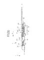
図1Aから図1Iには、磁石部21,31および形状結合部(Formschlussabschnitt)23,33を備えるクロージャ装置1の第1の典型的な実施形態が様々な視点から示されている。このようなクロージャ装置1は、概して、2つの部品を着脱自在に連結するために設けることができる。例えば、このようなクロージャ装置1を衣服または鞄に設けてもよい。
1A through 1I show a first typical embodiment of the
例えば図1Aに示されているように、クロージャ装置1は、第1クロージャ部2および第2クロージャ部3を有し、2つのクロージャ部2,3は閉じ方向Zに互いに接するように配置されて、クロージャ装置1を閉じることができる。各クロージャ部2,3は、実質的に各延在平面XY,X’Y’上に延在する基体20,30を有する。
For example, as shown in FIG. 1A, the
第1クロージャ部2の基体20には3つの第1磁石部21が設けられており、各場合において、2つの隣り合う磁石部21は、互いに離間しており、それらの間に中間空間22を形成している。第2磁石部31は、第1磁石部21に面する第2クロージャ部3の基体30の側に配置されている。
The
図1Aの拡大図から、各第1磁石部21が、第1磁化方向M1に磁化された第1永久磁石211を備え、この第1磁化方向M1は、各第1永久磁石211のN極NからS極Sを向く方向であることが明らかである。それにより、第2磁石部31も、第2磁化方向M2に磁化された第2永久磁石311を備え、この第2磁化方向M2は、第2永久磁石311のN極NからS極Sを向く方向である。クロージャ装置1を使用する際、永久磁石211,311は、第1磁石部21および第2磁石部31にそれぞれ設けられた凹部に配置される。
From the enlarged view of FIG. 1A, each
クロージャ装置1を閉じるためには、クロージャ装置1が図1Iに示された閉じ位置を取るように、第1クロージャ部2および第2クロージャ部3を閉じ方向Zに互いに接するように配置することができる。閉じ位置において、第1クロージャ部2および第2クロージャ部3の基体20,30の各延在平面XY,X’Y’は、実質的に互いに平行かつ閉じ方向Zと垂直な方向を向いている。
In order to close the
閉じ位置において、第2磁石部31が2つの隣り合う第1磁石部21の間に形成された中間空間(Zwischenraum)22に収容されることが、図1Iから明らかである。閉じ方向Zと実質的に垂直な方向を向く吸引磁力K1,K2は、N極NおよびS極Sが互いに向かい合う方向に従って、一方では第2磁石部31と、他方では中間空間22を形成している2つの第1磁石部21のそれぞれとの間に作用している。閉じ方向Zと垂直な方向に働く吸引磁力K1,K2は、クロージャ装置1を確実に閉じ位置に保持する。
It is clear from FIG. 1I that in the closed position, the
閉じ位置において吸引磁力K1,K2を発生させるために、永久磁石211,311は、第1磁化方向M1および第2磁化方向M2が互いに平行、かつ閉じ方向Zと実質的に垂直な方向を向くように、各磁石部21,31に設けられている。閉じ位置において、磁化方向M1,M2および吸引磁力K1,K2は、基体20,30の延在平面XY,X’Y’と実質的に平行である。
In order to generate attractive magnetic forces K1 and K2 at the closed position, the
以下においてより詳細に説明する図1Bから図1Iには、あくまでも例示的に考え得るクロージャ装置1を閉じるプロセスが図示されている。図1B,図1D,図1Fおよび図1Hにはそれぞれ、図1Aに記載のクロージャ装置1が図示されており、図1C,図1E,図1Gおよび図1Iには、それぞれ続けて、各切断線A−Aに沿った対応の断面図が示されている。
FIGS. 1B to 1I, which will be described in more detail below, illustrate the process of closing the
図1Bおよび図1Cには、クロージャ装置1の開いた状態が示されている。対照的に、図1Hおよび図1Iには、クロージャ装置1の閉じ位置が示されている。クロージャ装置1が閉じるプロセスの間に取り得る中間位置は、図1Dから図1Gに示されている。
1B and 1C show the
磁石部21に加えて、第1クロージャ部2は6つの形状結合部23を備え、そのうちの2つがそれぞれ磁石部21を側方から囲んでおり、各形状結合部は閉じ方向に対して傾斜した形状結合面(Formschlussflaeche)231を有する。3つの形状結合部23は、磁石部21と同様に、第1クロージャ部2の基体20に一定の間隔を空けて配置されている。また、第2クロージャ部3は2つの第2形状結合部33を備え、これらの第2形状結合部33は、第1形状結合部23に対して補完的な形状を有し、かつ第2磁石部31を側方から囲んでいる。各第2形状結合部は、閉じ方向Zに対して傾斜した形状結合面331を有する。
In addition to the
第1形状結合部23および第2形状結合部33は、クロージャ装置1の閉じ位置において互いに形状結合によって係合するように設けられており、閉じ方向Zとは反対方向の、クロージャ部2,3を互いに分離する方向へ向けられた互いに対するクロージャ部2,3の相対移動を防止する。換言すれば、第1クロージャ部2および第2クロージャ部3の形状結合部23,33は、閉じ位置において、閉じ方向Zに対して互いに形状結合によって係合している(hintergreifen)(図1Iを参照)。このため、第1形状結合部23の傾斜した形状結合面231は、第1クロージャ部2の基体20に面している。したがって、第2形状結合部33の形状結合面331は第2クロージャ部3の基体30に面している。
The first
2つのクロージャ部2,3を、形状結合部23,33を用いて形状結合によって係合することにより、クロージャ装置1の閉じ位置において確実な連結が得られる。これにより、クロージャ部2,3が閉じ方向Zとは反対方向の、クロージャ部2,3を互いに分離する方向に向かって相対移動することによってクロージャ装置1が意図せず開いてしまうことが防止される。また、形状結合部23,33を互いに形状結合させることにより、閉じ方向Zと垂直な方向にクロージャ部2,3に作用し得る外部のせん断力を吸収することが可能である。
By engaging the two
他の変形例(図示せず)において、第1形状結合部23および/または第2形状結合部33は、各クロージャ部2,3における典型的なメカニカルアンダーカット(“echten” mechanischen Hinterschnitt)によって形成してもよく、第1形状結合部23および/または第2形状結合部33はそれぞれ、閉じ方向Zと実質的に垂直に延びる少なくとも1つの形状結合面を備えていてもよい。
In another variant (not shown), the first shape joint 23 and / or the second shape joint 33 is formed by a typical mechanical undercut (“echten” mechanischen Hinterschnitt) in each
さらに、各第1案内部24,34は、2つのクロージャ部2,3に設けられている。図示された典型的な実施形態において、第1案内部24,34は、磁石部21,31を側方から囲む形状結合部23,33において閉じ方向Zに対して傾斜して延びる第1案内面241,341として構成されている。
Further, the
図1Gにあくまでも例として図示されているように、第1案内部24,34は、クロージャ部2,3を互いに適合させたとき、閉じ方向Zと垂直な方向への互いに対するクロージャ部2,3の相対移動R2を決定して、少なくとも1つの第1形状結合部23および少なくとも1つの第2形状結合部33を互いに形状結合によって係合させるように構成されている。この係合は、図1Iに示されている閉じ位置に対応する。
As shown in FIG. 1G as an example, the
このため、第1クロージャ部2の第1案内面241はそれぞれ、第2クロージャ部3の第1案内面341の上をスライドする第1接触部25を形成している。反対に、第2クロージャ部3の第1案内面341はそれぞれ、第1クロージャ部2の第1案内面241の上をスライドする第1接触部35を形成している。
Therefore, each of the first guide surfaces 241 of the
例えば、第2クロージャ部3が、閉じ方向Zに第1クロージャ部2に配置されたとき、第2クロージャ部3は、第1接触部35で第1クロージャ部2の第1案内面241上をスライドすることが可能である。これにより、第2クロージャ部3は、閉じ方向Zと垂直に偏向されて(図1Gに示された相対移動R2に対応する)、第1クロージャ部2および第2クロージャ部3の形状結合面231,331が互いに形状結合(formschluessig in Eingriff)によって係合し、閉じ方向Zと平行な、クロージャ部2,3を互いに分離する方向への相対移動を防止する。
For example, when the
第2クロージャ部3は、第1クロージャ部2の第1案内面241上でスライドするとき、閉じ方向Zと垂直にせん断力が加えられて移動が偏向され、結果的に閉じ位置への相対移動R2を生じさせる。このプロセスは、図1Gに示されているクロージャ装置1の中間位置から、図1Iに示されている閉じ位置へのステップに対応する。
When the
これにより、ユーザは、略閉じ方向Zにクロージャ部2,3を互いに接するように配置するだけでよいので、特に簡易な閉じプロセスが実現する。よって、形状係合部23,33を互いに形状結合によって係止することは、案内面241,341を用いることで、または接触部25,35を用いることで発生するせん断力によってほとんど自動的に行われ、結果的に相対移動R2が行われる。このとき、磁石部21,31の間の磁気吸引力により、閉じプロセスが付加的にサポートされる。
As a result, the user only needs to arrange the
図1Iに示されているように、閉じ位置において、第1磁石部21および第2磁石部31は、閉じ位置に移行させるために生じるせん断力が作用する方向と同一線上(すなわち、相対移動R2の方向)に続けて配置されている。第1磁石部21に設けられた第1永久磁石211の第1磁化方向M1、および第2磁石部31に設けられた第2永久磁石311の第2磁化方向M2は、互いに平行であり、閉じ方向Zと実質的に垂直な方向を向いている。第1磁石部21および第2磁石部31は、第1磁化方向M1および第2磁化方向M2に対して互いに続けて配置(hintereinander angeordnet)されている。
As shown in FIG. 1I, at the closed position, the
したがって、閉じ方向Zと垂直な方向における吸引磁力K1,K2は、外部のせん断力が磁力K1,K2を越えない限り、クロージャ部2,3に相対移動R2と反対方向に作用する外部のせん断力が加えられた場合であっても、クロージャ装置1を閉じ位置に保持する。したがって、クロージャ装置1が意図せず開いてしまうことを防止することが可能である。対照的に、クロージャ部2,3に対して相対移動R2の方向に作用する外部のせん断力は、閉じ位置における形状結合部23,33の形状結合による係合によって吸収することが可能である。
Therefore, the attractive magnetic forces K1 and K2 in the direction perpendicular to the closing direction Z act on the
第1案内部24,34に加えて、2つのクロージャ部2,3にはそれぞれ第2案内部27,37が設けられている。第2案内部27,37は、また、磁石部21,31を側方から囲む形状結合部23,33において、閉じ方向Zに対して傾斜して延びる第2案内面271,371として構成されている。
In addition to the
第2案内部27,37の機能は、図1Eに示された中間位置から図1Gに示された中間位置へのステップから明白である。したがって、第2案内部27,37は、クロージャ部2,3が互いに接するように配置されたとき、閉じ方向Zと垂直な方向への互いに対するクロージャ部2,3の第1の所定の相対移動R1を決定して、一方では、第1クロージャ部2の第1案内部24と、他方では第2クロージャ部3の第2案内部34と、を互いに接触させるように構成されている(図1Gを参照)。
The function of the second guides 27, 37 is obvious from the step from the intermediate position shown in FIG. 1E to the intermediate position shown in FIG. 1G. Therefore, when the
このため、第1クロージャ部2の第2案内面271はそれぞれ、第2クロージャ部3の第2案内面371の上でスライドする第2接触部26を形成している。反対に、第2クロージャ部3の第2案内面371はそれぞれ、第1クロージャ部2の第2案内面271の上でスライドする第2接触部36を形成している。
Therefore, the
例えば、第2クロージャ部3は、第1のステップにおいて、第1クロージャ部2の第2案内面271の上で第2クロージャ部の第2接触部36と共にスライドし、これにより、閉じ方向Zと垂直に偏向されて(図1Eに示される第1の相対移動R1に対応する)、第1クロージャ部2および第2クロージャ部3の第1案内面241,341を互いに接触させる(図1Gを参照)。
For example, in the first step, the
これにより、第2のステップにおいて、第2クロージャ部3は、図1Gおよび図1Iとの関連で既に説明したように、第2の相対移動R2において、第1クロージャ部2の形状結合部23の方向に第1案内部24に沿って移動し、その位置で係合し、クロージャ装置1の閉じ位置の実現が可能である。第2の相対移動R2は、第1の相対移動R1と反対方向に向いている。
As a result, in the second step, the
第2案内部27,37と第1案内部24,34との間の上述の相互作用により、クロージャ部2,3が互いに接するように配置されたときにある程度の許容性が確保され、これにより、ユーザにとってクロージャ装置1の閉じ動作が簡易化される。したがって、ユーザは、第1案内部27,37の領域において2つのクロージャ部2,3を互いに対して正確に配置することを意識する必要はない。
The above-mentioned interaction between the second guides 27 and 37 and the first guides 24 and 34 ensures a certain degree of tolerance when the
また、クロージャ部2,3が互いに接するように配置されたとき、第1クロージャ部2を、第2案内部37において偏向させることなく、他方のクロージャ部3の第1案内部34と直接接触させることも可能であることが明白である。このとき、第1案内部24,34の幅全体の領域において接触がなされるので、特に正確に配置することは必要でない。したがって、第1案内部24,34自体も位置付け動作の許容性に貢献し、これにより、クロージャ装置1の特に簡易な閉じプロセスに貢献する。
Further, when the
図2Aは、本発明に係るクロージャ装置1の第2の典型的な実施形態の拡大斜視図である。図2Bは、図2Aに記載のクロージャ装置1の平面図である。図2Cは、図2Bに示された切断線A−Aに沿った対応の断面図である。図2Dは、閉じ位置における第2の典型的な実施形態に記載のクロージャ装置1の断面図である。
FIG. 2A is an enlarged perspective view of a second typical embodiment of the
図2Aから図2Dに図示されたクロージャ装置1は、図1Aから図1Iと関連して説明したクロージャ装置1と同様の基本構造および機能を有する。したがって、第1の典型的な実施形態についての上記説明は、原則として、図2Aから図2Dに記載の第2の典型的な実施形態にも適用される。
The
しかしながら、第1の典型的な実施形態とは対照的に、図2Aから図2Dに記載のクロージャ装置1において、クロージャ装置に設けられた磁石部21,31および永久磁石211,311の両方が、それぞれ、非矩形状の平行四辺形の形状の断面を有する(特に、図2Cおよび図2Dを参照)。第1形状結合部23および第2形状結合部33はそれぞれ、閉じ方向Zに対して傾斜して延びる磁石部21,31の面によって形成されている。
However, in contrast to the first typical embodiment, in the
特に、(図2Aから図2Dの典型的な実施形態と同様に)少なくとも3つの第1磁石部21および結果的に少なくとも2つの中間空間22を有するカスケード式の実施形態において、この構成により次のような利点が得られる。第2クロージャ部3が、第1の中間空間22−1に第2クロージャ部が収容される第1の閉じ位置から外れて、第2の中間空間22−2に第2クロージャ部が収容される第2の閉じ位置に移動される場合、この移動は、平行四辺形形状の断面を有する前記磁石部の側面がその形状によって力Fを偏向させるので、閉じ方向Zとは反対方向に作用する力によってクロージャ装置1を開くことなく、閉じ方向Zと垂直な方向に加えられる力Fによって達成され得る。したがって、クロージャ装置1は、同様に、一方の方向にはブロックされ、他方の方向には容易に調節することが可能なフリーランニング(Freilauf)として作用する。また、クロージャ装置1の開き動作も特に簡易に行うことが可能である。
以下、本発明に含まれる態様を記す。
〔態様1〕2つの部品を着脱自在に連結するクロージャ装置(1)であって、
− 互いに離間し、かつその間に中間空間(22)を形成する少なくとも2つの第1磁石部(21)を有する第1クロージャ部(2)と、
− 少なくとも1つの第2磁石部(31)を有する第2クロージャ部(3)と、
を備え、
前記第1クロージャ部(2)および前記第2クロージャ部(3)は、前記クロージャ装置(1)が、前記少なくとも1つの第2磁石部(31)が前記中間空間(22)に少なくとも部分的に収容される閉じ位置を取るように、閉じ方向(Z)に互いに接するように配置することが可能であり、
前記閉じ位置において、前記閉じ方向(Z)と実質的に垂直な方向を向く吸引磁力(K1,K2)が、一方では前記少なくとも1つの第2磁石部(31)と、他方では前記中間空間(22)を形成している前記少なくとも2つの第1磁石部(21)のそれぞれと、の間に作用するクロージャ装置(1)において、
前記第1クロージャ部(2)は少なくとも1つの第1形状結合部(23)を有し、前記第2クロージャ部(3)は少なくとも1つの第2形状結合部(33)を有し、前記閉じ位置において、前記少なくとも1つの第1形状結合部(23)および前記少なくとも1つの第2形状結合部(33)が、互いに形状結合して、前記クロージャ部(2,3)が前記閉じ方向(Z)と平行に互いに対して相対移動することを防止することを特徴とするクロージャ装置(1)。
〔態様2〕態様1に記載のクロージャ装置(1)において、前記第1クロージャ部(2)が、互いに等間隔で離間した複数の第1磁石部(21)を有し、各場合において、2つの第1磁石部(21)がその間に、前記閉じ位置において、前記少なくとも1つの第2磁石部(31)を少なくとも部分的に収容するように構成された中間空間(22)を形成していることを特徴とするクロージャ装置(1)。
〔態様3〕2つの部品を着脱自在に連結するクロージャ装置(1)であって、
− 少なくとも1つの第1磁石部(21)および少なくとも1つの第1形状結合部(23)を有する第1クロージャ部(2)と、
− 少なくとも1つの第2磁石部(31)および少なくとも1つの第2形状結合部(33)を有する第2クロージャ部(3)と、
を備え、
前記第1クロージャ部(2)および前記第2クロージャ部(3)は、前記クロージャ装置(1)が、前記少なくとも1つの第1磁石部(21)と前記少なくとも1つの第2磁石部(31)の間に閉じ方向(Z)と実質的に垂直な方向を向く吸引磁力(K1,K2)が作用する閉じ位置を取るように、前記閉じ方向(Z)に互いに接するように配置することが可能であり、
さらに、前記閉じ位置において、前記少なくとも1つの第1形状結合部(23)および前記少なくとも1つの第2形状結合部(33)は、互いに形状結合によって係合して、前記クロージャ部(2,3)が前記閉じ方向(Z)と平行に互いに対して相対移動することを防止するクロージャ装置(1)において、
前記磁石部(21,31)の少なくとも一方は、非矩形状の平行四辺形の形状の断面を有しており、前記第1形状結合部(23)および/または前記第2形状結合部(33)は、前記閉じ方向(Z)に対して傾斜して延びる前記磁石部(21,31)の面によって形成されていることを特徴とするクロージャ装置(1)。
〔態様4〕態様3に記載のクロージャ装置(1)において、前記磁石部(21,31)の少なくとも一方は、断面が非矩形状の平行四辺形の形状である永久磁石(211,311)を備えることを特徴とするクロージャ装置(1)。
〔態様5〕態様1から4のいずれか一態様に記載のクロージャ装置(1)において、前記クロージャ部(2,3)の少なくとも一方に、少なくとも1つの第1案内部(24,34)が設けられており、この第1案内部(24、34)は、前記クロージャ部(2,3)が互いに接するように配置されたとき、前記閉じ方向(Z)と垂直な方向への互いに対する前記クロージャ部(2,3)の相対移動(R2)をプリセットして、前記少なくとも1つの第1形状結合部(23)および前記少なくとも1つの第2形状結合部(33)を互いに形状結合によって係合させるように構成されていることを特徴とするクロージャ装置(1)。
〔態様6〕2つの部品を着脱自在に連結するクロージャ装置(1)であって、
− 少なくとも1つの第1磁石部(21)および少なくとも1つの第1形状結合部(23)を有する第1クロージャ部(2)と、
− 少なくとも1つの第2磁石部(31)および少なくとも1つの第2形状結合部(33)を有する第2クロージャ部(3)と、
を備え、
前記第1クロージャ部(2)および前記第2クロージャ部(3)は、前記クロージャ装置(1)が、前記少なくとも1つの第1磁石部(21)と前記少なくとも1つの第2磁石部(31)の間に閉じ方向(Z)と実質的に垂直な方向を向く吸引磁力(K1,K2)が作用する閉じ位置を取るように、前記閉じ方向(Z)に互いに接するように配置し、かつ前記閉じ方向(Z)と垂直に適用されるせん断力を加えることが可能であり、
さらに、前記閉じ位置において、前記少なくとも1つの第1形状結合部(23)および前記少なくとも1つの第2形状結合部(33)は、互いに形状結合によって係合して、前記クロージャ部(2,3)が前記閉じ方向(Z)と平行に互いに対して相対移動することを防止するクロージャ装置(1)において、
前記クロージャ部(2,3)の少なくとも一方に、少なくとも1つの第1案内部(24,34)が設けられており、前記第1案内部(24、34)は、前記クロージャ部(2,3)が互いに接するように配置されたとき、前記閉じ方向(Z)と垂直な方向への互いに対する前記クロージャ部(2,3)の相対移動(R2)をプリセットして、前記少なくとも1つの第1形状結合部(23)および前記少なくとも1つの第2形状結合部(33)を互いに形状結合によって係合させるように構成されており、
前記少なくとも1つの第1磁石部(21)および前記少なくとも1つの第2磁石部(31)が互いに続けて、かつ前記閉じ位置に移行させるために生じるせん断力が作用する方向と同一線上に配置されていることを特徴とするクロージャ装置(1)。
〔態様7〕態様6に記載のクロージャ装置(1)において、前記磁石部(21,31)の少なくとも一方は、非矩形状の平行四辺形の形状の断面を有しており、前記第1形状結合部(23)および/または前記第2形状結合部(33)は、前記閉じ方向(Z)に対して傾斜して延びる前記磁石部(21,31)の面によって形成されていることを特徴とするクロージャ装置(1)。
〔態様8〕態様5から7のいずれか一態様に記載のクロージャ装置(1)において、前記少なくとも1つの第1案内部(24,34)は、前記閉じ方向(Z)に対して傾斜して延びる前記磁石部(21,31)の面によって形成されていることを特徴とするクロージャ装置(1)。
〔態様9〕2つの部品を着脱自在に連結するクロージャ装置(1)であって、
− 少なくとも1つの第1磁石部(21)および少なくとも1つの第1形状結合部(23)を有する第1クロージャ部(2)と、
− 少なくとも1つの第2磁石部(31)および少なくとも1つの第2形状結合部(33
)を有する第2クロージャ部(3)と、
を備え、
前記第1クロージャ部(2)および前記第2クロージャ部(3)は、前記クロージャ装置(1)が、前記少なくとも1つの第1磁石部(21)と前記少なくとも1つの第2磁石部(31)の間に閉じ方向(Z)と実質的に垂直な方向を向く吸引磁力(K1,K2)が作用する閉じ位置を取るように、前記閉じ方向(Z)に互いに接するように配置することが可能であり、
さらに、前記閉じ位置において、前記少なくとも1つの第1形状結合部(23)および前記少なくとも1つの第2形状結合部(33)は、互いに形状結合によって係合して、前記クロージャ部(2,3)が前記閉じ方向(Z)と平行に互いに対して相対移動することを防止するクロージャ装置(1)において、
少なくとも一方のクロージャ部(2,3)に、少なくとも1つの第1案内部(24,34)および少なくとも1つの第2案内部(27,37)が設けられており、
前記少なくとも1つの第2案内部(27,37)は、前記クロージャ部(2,3)が互いに接するように配置されたとき、前記閉じ方向(Z)と垂直な方向への互いに対する前記クロージャ部(2,3)の第1の相対移動(R1)をプリセットして、それぞれの他方のクロージャ部(3,2)を前記少なくとも1つの第1案内部(24,34)と接触させるように構成されており、
前記少なくとも1つの第1案内部(24,34)は、前記クロージャ部(2,3)が互いに接するように配置されたとき、前記閉じ方向(Z)と垂直な方向への互いに対する前記クロージャ部(2,3)の第2の相対移動(R2)をプリセットして、前記少なくとも1つの第1形状結合部(23)および前記少なくとも1つの第2形状結合部(33)を互いに形状結合によって係合させるように構成されていることを特徴とするクロージャ装置(1)。
〔態様10〕態様5から9のいずれか一態様に記載のクロージャ装置(1)において、前記少なくとも1つの第1案内部(24,34)は、前記閉じ方向(Z)に対して傾斜して延びる少なくとも1つの第1案内面(241,341)を備え、および/または前記少なくとも1つの第2案内部(27,37)は、前記閉じ方向(Z)に対して傾斜して延びる少なくとも1つの第2案内面(271,371)を備えることを特徴とするクロージャ装置(1)。
〔態様11〕態様10に記載のクロージャ装置(1)において、それぞれの他方のクロージャ部(3,2)は、前記第1案内面(241,341)の上をスライドする少なくとも1つの第1接触部(35,25)、および/または前記第2案内面(271,371)の上をスライドする少なくとも1つの第2接触部(36,26)を有することを特徴とするクロージャ装置(1)。
〔態様12〕態様1から11のいずれか一態様に記載のクロージャ装置(1)において、前記少なくとも1つの第1形状結合部(23)および/または前記少なくとも1つの第2形状結合部(33)は、前記閉じ方向(Z)に対して傾斜して延びる形状結合面(231,331)を有することを特徴とするクロージャ装置(1)。
〔態様13〕態様1から12のいずれか一態様に記載のクロージャ装置(1)において、前記少なくとも1つの第1形状結合部(23)および/または前記少なくとも1つの第2形状結合部(33)は、それぞれの前記クロージャ部(2,3)におけるアンダーカットによって形成されていることを特徴とするクロージャ装置(1)。
〔態様14〕態様13に記載のクロージャ装置(1)において、それぞれの前記クロージャ部(2,3)におけるアンダーカットによって形成された前記第1形状結合部(23)および/または前記第2形状結合部(33)は、前記閉じ方向(Z)に対して実質的に垂直に延びる少なくとも1つの形状結合面を有することを特徴とするクロージャ装置(1)。
〔態様15〕態様1から3のいずれか一態様に記載のクロージャ装置(1)において、前記少なくとも1つの第1磁石部(21)が、第1磁化方向(M1)に磁化された少なくとも1つの第1永久磁石(211)を備え、かつ前記少なくとも1つの第2磁石部(31)が、第2磁化方向(M2)に磁化された少なくとも1つの第2永久磁石(311)を備えることを特徴とするクロージャ装置(1)。
〔態様16〕態様15に記載のクロージャ装置(1)において、前記クロージャ装置(1)の前記閉じ位置において、前記少なくとも1つの第1磁石部(21)および前記少なくとも1つの第2磁石部(31)は、前記第1磁化方向(M1)および前記第2磁化方向(M2)が互いに平行、かつ前記閉じ方向(Z)と実質的に垂直な方向を向くように設けられていることを特徴とするクロージャ装置(1)。
〔態様17〕態様16に記載のクロージャ装置(1)において、前記クロージャ装置(1)の前記閉じ位置において、前記少なくとも1つの第1磁石部(21)および前記少なくとも1つの第2磁石部(31)は、前記第1磁化方向(M1)および前記第2磁化方向(M2)に対して続けて配置されていることを特徴とするクロージャ装置(1)。
〔態様18〕態様1から17のいずれか一態様に記載のクロージャ装置(1)において、前記磁石部(21,31)の少なくとも一方および/または前記永久磁石(211,311)の少なくとも一方は、非矩形状の平行四辺形の形状の断面を有することを特徴とするクロージャ装置(1)。
〔態様19〕態様1から18のいずれか一態様に記載のクロージャ装置(1)において、前記第1クロージャ部(2)および前記第2クロージャ部(3)は、前記第1永久磁石(211)および前記第2永久磁石(311)のそれぞれの前記磁化方向(M1,M2)は別にして構造的に同じに形成されていることを特徴とするクロージャ装置(1)。
〔態様20〕態様1から19のいずれか一態様に記載のクロージャ装置(1)において、前記第2クロージャ部(3)は、互いに等間隔で離間した複数の第2磁石部(31)を備え、各場合において、2つ第2磁石部(31)がその間に、前記閉じ位置において、前記少なくとも1つの第1磁石部(21)を少なくとも部分的に収容するように構成された中間空間(32)を形成していることを特徴とするクロージャ装置(1)。
In particular, in a cascaded embodiment having at least three
Hereinafter, aspects included in the present invention will be described.
[Aspect 1] A closure device (1) for detachably connecting two parts.
-A first closure portion (2) having at least two first magnet portions (21) separated from each other and forming an intermediate space (22) between them.
-A second closure portion (3) having at least one second magnet portion (31) and
With
In the first closure portion (2) and the second closure portion (3), the closure device (1) has the at least one second magnet portion (31) at least partially in the intermediate space (22). It can be arranged so as to be in contact with each other in the closing direction (Z) so as to take a closed position to be accommodated.
At the closing position, the attractive magnetic forces (K1, K2) oriented in a direction substantially perpendicular to the closing direction (Z) are the at least one second magnet portion (31) on the one hand and the intermediate space (K1) on the other hand. In the closure device (1) acting between each of the at least two first magnet portions (21) forming 22).
The first closure portion (2) has at least one first shape coupling portion (23), the second closure portion (3) has at least one second shape coupling portion (33), and the closure. At the position, the at least one first shape coupling portion (23) and the at least one second shape coupling portion (33) are shape-bonded to each other, and the closure portions (2, 3) are in the closing direction (Z). ), The closure device (1), which prevents relative movement with respect to each other.
[Aspect 2] In the closure device (1) according to the first aspect, the first closure portion (2) has a plurality of first magnet portions (21) separated from each other at equal intervals, and in each case, 2 One first magnet portion (21) forms an intermediate space (22) in between, which is configured to at least partially accommodate the at least one second magnet portion (31) at the closed position. A closure device (1).
[Aspect 3] A closure device (1) for detachably connecting two parts.
-A first closure portion (2) having at least one first magnet portion (21) and at least one first shape coupling portion (23).
-A second closure portion (3) having at least one second magnet portion (31) and at least one second shape coupling portion (33).
With
In the first closure portion (2) and the second closure portion (3), the closure device (1) has the at least one first magnet portion (21) and the at least one second magnet portion (31). It is possible to arrange them so as to be in contact with each other in the closing direction (Z) so as to take a closing position in which attractive magnetic forces (K1 and K2) facing in a direction substantially perpendicular to the closing direction (Z) act between the two. And
Further, at the closed position, the at least one first shape coupling portion (23) and the at least one second shape coupling portion (33) are engaged with each other by shape coupling, and the closure portions (2, 3) are engaged with each other. ) Relative to each other in parallel with the closing direction (Z) in the closure device (1).
At least one of the magnet portions (21, 31) has a non-rectangular parallelogram-shaped cross section, and the first shape coupling portion (23) and / or the second shape coupling portion (33). ) Is a closure device (1), characterized in that it is formed by the surfaces of the magnet portions (21, 31) that extend at an angle with respect to the closing direction (Z).
[Aspect 4] In the closure device (1) according to the third aspect, at least one of the magnet portions (21, 31) is a permanent magnet (21, 311) having a non-rectangular parallelogram shape in cross section. A closure device (1) characterized by being provided.
[Aspect 5] In the closure device (1) according to any one of
[Aspect 6] A closure device (1) for detachably connecting two parts.
-A first closure portion (2) having at least one first magnet portion (21) and at least one first shape coupling portion (23).
-A second closure portion (3) having at least one second magnet portion (31) and at least one second shape coupling portion (33).
With
In the first closure portion (2) and the second closure portion (3), the closure device (1) has the at least one first magnet portion (21) and the at least one second magnet portion (31). The magnets are arranged so as to be in contact with each other in the closing direction (Z) so as to take a closing position in which attractive magnetic forces (K1 and K2) oriented in a direction substantially perpendicular to the closing direction (Z) act. It is possible to apply a shear force applied perpendicular to the closing direction (Z),
Further, at the closed position, the at least one first shape coupling portion (23) and the at least one second shape coupling portion (33) are engaged with each other by shape coupling, and the closure portions (2, 3) are engaged with each other. ) Relative to each other in parallel with the closing direction (Z) in the closure device (1).
At least one first guide portion (24, 34) is provided on at least one of the closure portions (2, 3), and the first guide portion (24, 34) is the closure portion (2, 3). ) Are arranged so as to be in contact with each other, the relative movement (R2) of the closure portions (2, 3) with respect to each other in the direction perpendicular to the closing direction (Z) is preset, and the at least one first. The shape coupling portion (23) and the at least one second shape coupling portion (33) are configured to be engaged with each other by shape coupling.
The at least one first magnet portion (21) and the at least one second magnet portion (31) are arranged in the same line as each other and in the direction in which the shearing force generated for shifting to the closed position acts. A closure device (1).
[Aspect 7] In the closure device (1) according to the sixth aspect, at least one of the magnet portions (21, 31) has a non-rectangular parallelogram-shaped cross section, and the first shape. The coupling portion (23) and / or the second shape coupling portion (33) is characterized in that it is formed by a surface of the magnet portion (21, 31) extending inclining with respect to the closing direction (Z). Closure device (1).
[Aspect 8] In the closure device (1) according to any one of aspects 5 to 7, the at least one first guide portion (24, 34) is inclined with respect to the closing direction (Z). A closure device (1) characterized by being formed by the surfaces of the extending magnet portions (21, 31).
[Aspect 9] A closure device (1) for detachably connecting two parts.
-A first closure portion (2) having at least one first magnet portion (21) and at least one first shape coupling portion (23).
-At least one second magnet part (31) and at least one second shape coupling part (33)
2) with a second closure (3) and
With
In the first closure portion (2) and the second closure portion (3), the closure device (1) has the at least one first magnet portion (21) and the at least one second magnet portion (31). It is possible to arrange them so as to be in contact with each other in the closing direction (Z) so as to take a closing position in which attractive magnetic forces (K1 and K2) facing in a direction substantially perpendicular to the closing direction (Z) act between the two. And
Further, at the closed position, the at least one first shape coupling portion (23) and the at least one second shape coupling portion (33) are engaged with each other by shape coupling, and the closure portions (2, 3) are engaged with each other. ) Relative to each other in parallel with the closing direction (Z) in the closure device (1).
At least one closure portion (2, 3) is provided with at least one first guide portion (24,34) and at least one second guide portion (27, 37).
The at least one second guide portion (27, 37) is the closure portion with respect to each other in a direction perpendicular to the closing direction (Z) when the closure portions (2, 3) are arranged so as to be in contact with each other. The first relative movement (R1) of (2, 3) is preset so that the other closure portion (3, 2) is brought into contact with the at least one first guide portion (24, 34). Has been
The at least one first guide portion (24, 34) is the closure portion with respect to each other in a direction perpendicular to the closing direction (Z) when the closure portions (2, 3) are arranged so as to be in contact with each other. By presetting the second relative movement (R2) of (2, 3), the at least one first shape coupling portion (23) and the at least one second shape coupling portion (33) are engaged with each other by shape coupling. A closure device (1) characterized in that it is configured to fit.
[Aspect 10] In the closure device (1) according to any one of aspects 5 to 9, the at least one first guide portion (24, 34) is inclined with respect to the closing direction (Z). It comprises at least one extending first guide surface (241,341) and / or at least one second guide portion (27,37) extending at an angle with respect to the closing direction (Z). A closure device (1) comprising a second guide surface (271,371).
[Aspect 11] In the closure device (1) according to the aspect 10, each of the other closure portions (3, 2) slides on the first guide surface (241, 341) at least one first contact. A closure device (1) comprising a portion (35,25) and / or at least one second contact portion (36,26) that slides over the second guide surface (271,371).
[Aspect 12] In the closure device (1) according to any one of
[Aspect 13] In the closure device (1) according to any one of
[Aspect 14] In the closure device (1) according to the thirteenth aspect, the first shape coupling portion (23) and / or the second shape coupling formed by the undercut in each of the closure portions (2, 3). The closure device (1), characterized in that the portion (33) has at least one shape coupling surface extending substantially perpendicular to the closing direction (Z).
[Aspect 15] In the closure device (1) according to any one of
[Aspect 16] In the closure device (1) according to aspect 15, at least one first magnet portion (21) and at least one second magnet portion (31) at the closed position of the closure device (1). ) Is provided so that the first magnetization direction (M1) and the second magnetization direction (M2) are parallel to each other and substantially perpendicular to the closing direction (Z). Closure device (1).
[Aspect 17] In the closure device (1) according to aspect 16, at least one first magnet portion (21) and at least one second magnet portion (31) at the closed position of the closure device (1). ) Is a closure device (1) that is continuously arranged with respect to the first magnetization direction (M1) and the second magnetization direction (M2).
[Aspect 18] In the closure device (1) according to any one of
[Aspect 19] In the closure device (1) according to any one of
[Aspect 20] In the closure device (1) according to any one of
1 クロージャ装置
2 第1クロージャ部
20 第1クロージャ部の基体
21 第1磁石部
211 第1永久磁石
22,22−1,22−2 中間空間
23 第1形状結合部
231 第1形状結合面
24 第1案内部
241 第1案内面
25 第1接触部
26 第2接触部
27 第2案内部
271 第2案内面
3 第2クロージャ部
30 第2クロージャ部の基体
31 第2磁石部
311 第2永久磁石
33 第2形状結合部
331 第2形状結合面
34 第1案内部
341 第1案内面
35 第1接触部
36 第2接触部
37 第2案内部
371 第2案内面
F 力
K1,K2 磁力
M1 第1磁化方向
M2 第2磁化方向
N N極
R1,R2 相対移動
S S極
XY,X’Y’ 基体の延在平面
Z 閉じ方向
1
Claims (20)
− 互いに離間し、かつその間に中間空間(22)を形成する少なくとも2つの第1磁石部(21)を有する第1クロージャ部(2)と、
− 少なくとも1つの第2磁石部(31)を有する第2クロージャ部(3)と、
を備え、
前記第1クロージャ部(2)および前記第2クロージャ部(3)は、前記クロージャ装置(1)が、前記少なくとも1つの第2磁石部(31)が前記中間空間(22)に少なくとも部分的に収容される閉じ位置を取るように、閉じ方向(Z)に互いに接するように配置することが可能であり、
前記閉じ位置において、前記閉じ方向(Z)と実質的に垂直な方向を向く吸引磁力(K1,K2)が、一方では前記少なくとも1つの第2磁石部(31)と、他方では前記中間空間(22)を形成している前記少なくとも2つの第1磁石部(21)のそれぞれと、の間に作用するクロージャ装置(1)において、
前記第1クロージャ部(2)は少なくとも1つの第1形状結合部(23)を有し、前記第2クロージャ部(3)は少なくとも1つの第2形状結合部(33)を有し、前記閉じ位置において、前記少なくとも1つの第1形状結合部(23)および前記少なくとも1つの第2形状結合部(33)が、互いに形状結合して、前記クロージャ部(2,3)が前記閉じ方向(Z)と平行に互いに対して相対移動することを防止し、
前記少なくとも1つの第1形状結合部(23)は傾斜して閉じ方向(Z)に延びている第1形状結合面(231)を、および前記少なくとも1つの第2形状結合部(33)は傾斜して閉じ方向(Z)に延びている第2形状結合面(331)を、有しており、
前記第1形状結合面(231)と前記第2形状結合面(331)とは、閉じ位置において形状結合により互いに接していることを特徴とするクロージャ装置(1)。 A closure device (1) that detachably connects two parts.
-A first closure portion (2) having at least two first magnet portions (21) separated from each other and forming an intermediate space (22) between them.
-A second closure portion (3) having at least one second magnet portion (31) and
With
In the first closure portion (2) and the second closure portion (3), the closure device (1) has the at least one second magnet portion (31) at least partially in the intermediate space (22). It can be arranged so as to be in contact with each other in the closing direction (Z) so as to take a closed position to be accommodated.
At the closing position, the attractive magnetic forces (K1, K2) oriented in a direction substantially perpendicular to the closing direction (Z) are the at least one second magnet portion (31) on the one hand and the intermediate space (K1) on the other hand. In the closure device (1) acting between each of the at least two first magnet portions (21) forming 22).
The first closure portion (2) has at least one first shape coupling portion (23), the second closure portion (3) has at least one second shape coupling portion (33), and the closure. At the position, the at least one first shape coupling portion (23) and the at least one second shape coupling portion (33) are shape-bonded to each other, and the closure portions (2, 3) are in the closing direction (Z). ) To prevent relative movement with respect to each other ,
The at least one first shape joint (23) is inclined so that the first shape joint surface (231) extends in the closing direction (Z), and the at least one second shape joint (33) is inclined. It has a second shape coupling surface (331) extending in the closing direction (Z).
The closure device (1), wherein the first shape coupling surface (231) and the second shape coupling surface (331) are in contact with each other by shape coupling at a closed position .
いに等間隔で離間した複数の第1磁石部(21)を有し、各場合において、2つの第1磁
石部(21)がその間に、前記閉じ位置において、前記少なくとも1つの第2磁石部(3
1)を少なくとも部分的に収容するように構成された中間空間(22)を形成しているこ
とを特徴とするクロージャ装置(1)。 In the closure device (1) according to claim 1, the first closure portion (2) has a plurality of first magnet portions (21) separated from each other at equal intervals, and in each case, two first magnet portions (21). The magnet portion (21) is in the meantime, and at the closed position, the at least one second magnet portion (3).
A closure device (1) characterized by forming an intermediate space (22) configured to accommodate 1) at least partially.
− 少なくとも1つの第1磁石部(21)および少なくとも1つの第1形状結合部(23
)を有する第1クロージャ部(2)と、
− 少なくとも1つの第2磁石部(31)および少なくとも1つの第2形状結合部(33
)を有する第2クロージャ部(3)と、
を備え、
前記第1クロージャ部(2)および前記第2クロージャ部(3)は、前記クロージャ装
置(1)が、前記少なくとも1つの第1磁石部(21)と前記少なくとも1つの第2磁石
部(31)の間に閉じ方向(Z)と実質的に垂直な方向を向く吸引磁力(K1,K2)が
作用する閉じ位置を取るように、前記閉じ方向(Z)に互いに接するように配置すること
が可能であり、
さらに、前記閉じ位置において、前記少なくとも1つの第1形状結合部(23)および
前記少なくとも1つの第2形状結合部(33)は、互いに形状結合によって係合して、前
記クロージャ部(2,3)が前記閉じ方向(Z)と平行に互いに対して相対移動すること
を防止するクロージャ装置(1)において、
前記磁石部(21,31)の少なくとも一方は、非矩形状の平行四辺形の形状の断面を
有しており、前記第1形状結合部(23)および/または前記第2形状結合部(33)は
、前記閉じ方向(Z)に対して傾斜して延びる前記磁石部(21,31)の面によって形
成されていることを特徴とするクロージャ装置(1)。 A closure device (1) that detachably connects two parts.
-At least one first magnet part (21) and at least one first shape coupling part (23)
1) with a closure (2) and
-At least one second magnet part (31) and at least one second shape coupling part (33)
2) with a second closure (3) and
With
In the first closure portion (2) and the second closure portion (3), the closure device (1) has the at least one first magnet portion (21) and the at least one second magnet portion (31). It is possible to arrange them so as to be in contact with each other in the closing direction (Z) so as to take a closing position in which attractive magnetic forces (K1 and K2) facing in a direction substantially perpendicular to the closing direction (Z) act between the two. And
Further, at the closed position, the at least one first shape coupling portion (23) and the at least one second shape coupling portion (33) are engaged with each other by shape coupling, and the closure portions (2, 3) are engaged with each other. ) Relative to each other in parallel with the closing direction (Z) in the closure device (1).
At least one of the magnet portions (21, 31) has a non-rectangular parallelogram-shaped cross section, and the first shape coupling portion (23) and / or the second shape coupling portion (33). ) Is a closure device (1), characterized in that it is formed by the surfaces of the magnet portions (21, 31) that extend at an angle with respect to the closing direction (Z).
とも一方は、断面が非矩形状の平行四辺形の形状である永久磁石(211,311)を備
えることを特徴とするクロージャ装置(1)。 In the closure device (1) according to claim 3, at least one of the magnet portions (21, 31) is provided with a permanent magnet (21, 311) having a parallelogram shape with a non-rectangular cross section. A featured closure device (1).
− 互いに離間し、かつその間に中間空間(22)が形成されている少なくとも2つの第1磁石部(21)および少なくとも1つの第1形状結合部(23)を有する第1クロージャ部(2)と、
− 少なくとも1つの第2磁石部(31)および少なくとも1つの第2形状結合部(33)を有する第2クロージャ部(3)と、
を備え、
前記第1クロージャ部(2)および前記第2クロージャ部(3)は、前記クロージャ装置(1)が、前記少なくとも1つの第1磁石部(21)と前記少なくとも1つの第2磁石部(31)の間に閉じ方向(Z)と実質的に垂直な方向を向く吸引磁力(K1,K2)が作用する閉じ位置を取るように、前記閉じ方向(Z)に互いに接するように配置し、かつ前記閉じ方向(Z)と垂直に適用されるせん断力を加えることが可能であり、
前記少なくとも1つの第2磁石部(31)は、少なくとも部分的に前記中間空間(22)に収容されており、
一方では前記少なくとも1つの第2磁石部(31)と、他方では前記中間空間(22)を形成している前記少なくとも2つの第1磁石部(21)の各々と、の間の閉じ位置において、本質的にZ方向に垂直に向けられた磁力(K1,K2)を作用させ、
さらに、前記閉じ位置において、前記少なくとも1つの第1形状結合部(23)および前記少なくとも1つの第2形状結合部(33)は、互いに形状結合によって係合して、前記クロージャ部(2,3)が前記閉じ方向(Z)と平行に互いに対して相対移動することを防止するクロージャ装置(1)において、
前記クロージャ部(2,3)の少なくとも一方に、少なくとも1つの第1案内部(24,34)が設けられており、前記第1案内部(24、34)は、前記クロージャ部(2,3)が互いに接するように配置されたとき、前記閉じ方向(Z)と垂直な方向への互いに対する前記クロージャ部(2,3)の相対移動(R2)をプリセットして、前記少なくとも1つの第1形状結合部(23)および前記少なくとも1つの第2形状結合部(33)を互いに形状結合によって係合させるように構成されており、
前記少なくとも1つの第1磁石部(21)および前記少なくとも1つの第2磁石部(31)が互いに続けて、かつ前記閉じ位置に移行させるために生じるせん断力が作用する方向と同一線上に配置されていることを特徴とするクロージャ装置(1)。 A closure device (1) that detachably connects two parts.
-With a first closure portion (2) having at least two first magnet portions (21) and at least one first shape coupling portion (23) separated from each other and having an intermediate space (22) formed between them. ,
-A second closure portion (3) having at least one second magnet portion (31) and at least one second shape coupling portion (33).
With
In the first closure portion (2) and the second closure portion (3), the closure device (1) has the at least one first magnet portion (21) and the at least one second magnet portion (31). The magnets are arranged so as to be in contact with each other in the closing direction (Z) so as to take a closing position in which attractive magnetic forces (K1 and K2) oriented in a direction substantially perpendicular to the closing direction (Z) act. It is possible to apply a shear force applied perpendicular to the closing direction (Z),
The at least one second magnet portion (31) is at least partially housed in the intermediate space (22).
At a closed position between the at least one second magnet portion (31) on the one hand and each of the at least two first magnet portions (21) forming the intermediate space (22) on the other hand. A magnetic force (K1, K2) that is essentially directed perpendicular to the Z direction is applied.
Further, at the closed position, the at least one first shape coupling portion (23) and the at least one second shape coupling portion (33) are engaged with each other by shape coupling, and the closure portions (2, 3) are engaged with each other. ) Relative to each other in parallel with the closing direction (Z) in the closure device (1).
At least one first guide portion (24, 34) is provided on at least one of the closure portions (2, 3), and the first guide portion (24, 34) is the closure portion (2, 3). ) Are arranged so as to be in contact with each other, the relative movement (R2) of the closure portions (2, 3) with respect to each other in the direction perpendicular to the closing direction (Z) is preset, and the at least one first. The shape coupling portion (23) and the at least one second shape coupling portion (33) are configured to be engaged with each other by shape coupling.
The at least one first magnet portion (21) and the at least one second magnet portion (31) are arranged in the same line as each other and in the direction in which the shearing force generated for shifting to the closed position acts. A closure device (1).
とも一方は、非矩形状の平行四辺形の形状の断面を有しており、前記第1形状結合部(2
3)および/または前記第2形状結合部(33)は、前記閉じ方向(Z)に対して傾斜し
て延びる前記磁石部(21,31)の面によって形成されていることを特徴とするクロー
ジャ装置(1)。 In the closure device (1) according to claim 6, at least one of the magnet portions (21, 31) has a non-rectangular parallelogram-shaped cross section, and the first shape coupling portion (1). 2
3) and / or the second shape coupling portion (33) is formed by a surface of the magnet portion (21, 31) extending inclined with respect to the closing direction (Z). Device (1).
磁石部(21,31)の面によって形成されていることを特徴とするクロージャ装置(1
)。 In the closure device (1) according to claim 6 , the at least one first guide portion (24,34) is a magnet portion (21, 31) extending in an inclined manner with respect to the closing direction (Z). A closure device (1) characterized by being formed by surfaces.
).
− 互いから間隔を置いて、互いの間に一つの中間空間(22)を形成する少なくとも2つの第1磁石部(21)、および少なくとも1つの第1形状結合部(23)を有する第1クロージャ部(2)と、
− 少なくとも1つの第2磁石部(31)および少なくとも1つの第2形状結合部(33
)を有する第2クロージャ部(3)と、
を備え、 前記第1クロージャ部(2)と前記第2クロージャ部(3)は、閉じ方向(Z)に沿って互いに接して、前記クロージャ装置(1)は閉位置をとり、
前記少なくとも1つの第2磁石部(31)は、前記中間空間(22)に少なくとも部分的に収容され、
閉位置において、一方では、前記少なくとも1つの第2磁石部(31)と、他方では、前記中間空間(22)を形成する前記少なくとも2つの第1の磁石部(21)のいずれもと、それぞれ、本質的に閉じ方向(Z)に垂直に向けられた吸引磁力(K1,K2)を作用させ、
さらに、前記閉じ位置において、前記少なくとも1つの第1形状結合部(23)および
前記少なくとも1つの第2形状結合部(33)は、互いに形状結合によって係合して、前
記クロージャ部(2,3)が前記閉じ方向(Z)と平行に互いに対して相対移動すること
を防止するクロージャ装置(1)において、
少なくとも一方のクロージャ部(2,3)に、少なくとも1つの第1案内部(24,34)および少なくとも1つの第2案内部(27,37)が設けられており、
前記少なくとも1つの第2案内部(27,37)は、前記クロージャ部(2,3)が互
いに接するように配置されたとき、前記閉じ方向(Z)と垂直な方向への互いに対する前
記クロージャ部(2,3)の第1の相対移動(R1)をプリセットして、それぞれの他方
のクロージャ部(3,2)を前記少なくとも1つの第1案内部(24,34)と接触させ
るように構成されており、
前記少なくとも1つの第1案内部(24,34)は、前記クロージャ部(2,3)が互
いに接するように配置されたとき、前記閉じ方向(Z)と垂直な方向への互いに対する前
記クロージャ部(2,3)の第2の相対移動(R2)をプリセットして、前記少なくとも
1つの第1形状結合部(23)および前記少なくとも1つの第2形状結合部(33)を互
いに形状結合によって係合させるように構成されていることを特徴とするクロージャ装置
(1)。 A closure device (1) that detachably connects two parts.
-A first closure with at least two first magnets (21) and at least one first shape coupling (23) that form an intermediate space (22) between them, spaced from each other. Part (2) and
-At least one second magnet part (31) and at least one second shape coupling part (33)
2) with a second closure (3) and
The first closure portion (2) and the second closure portion (3) are in contact with each other along the closing direction (Z), and the closure device (1) takes a closed position.
The at least one second magnet portion (31) is at least partially housed in the intermediate space (22).
In the closed position, on the one hand, both of the at least one second magnet portion (31) and, on the other hand, the at least two first magnet portions (21) forming the intermediate space (22), respectively. The attractive magnetic force (K1, K2), which is essentially directed perpendicular to the closing direction (Z), is applied.
Further, at the closed position, the at least one first shape coupling portion (23) and the at least one second shape coupling portion (33) are engaged with each other by shape coupling, and the closure portions (2, 3) are engaged with each other. ) Relative to each other in parallel with the closing direction (Z) in the closure device (1).
At least one closure portion (2, 3) is provided with at least one first guide portion (24,34) and at least one second guide portion (27, 37).
The at least one second guide portion (27, 37) is the closure portion with respect to each other in a direction perpendicular to the closing direction (Z) when the closure portions (2, 3) are arranged so as to be in contact with each other. The first relative movement (R1) of (2, 3) is preset so that the other closure portion (3, 2) is brought into contact with the at least one first guide portion (24, 34). Has been
The at least one first guide portion (24, 34) is the closure portion with respect to each other in a direction perpendicular to the closing direction (Z) when the closure portions (2, 3) are arranged so as to be in contact with each other. By presetting the second relative movement (R2) of (2, 3), the at least one first shape coupling portion (23) and the at least one second shape coupling portion (33) are engaged with each other by shape coupling. A closure device (1) characterized in that it is configured to fit.
3,2)は、前記第1案内面(241,341)の上をスライドする少なくとも1つの第
1接触部(35,25)、および/または前記第2案内面(271,371)の上をスラ
イドする少なくとも1つの第2接触部(36,26)を有することを特徴とするクロージ
ャ装置(1)。 In the closure device (1) according to claim 10, each other closure portion (
3,2) are on at least one first contact portion (35, 25) sliding on the first guide surface (241, 341) and / or on the second guide surface (271, 371). A closure device (1) comprising at least one second contact portion (36, 26) that slides.
,3)におけるアンダーカットによって形成された前記第1形状結合部(23)および/
または前記第2形状結合部(33)は、前記閉じ方向(Z)に対して実質的に垂直に延び
る少なくとも1つの形状結合面を有することを特徴とするクロージャ装置(1)。 In the closure device (1) according to claim 13, each of the closure portions (2).
, 3) The first shape connecting portion (23) formed by the undercut and /
Alternatively, the closure device (1), wherein the second shape coupling portion (33) has at least one shape coupling surface extending substantially perpendicular to the closing direction (Z).
も1つの第1磁石部(21)が、第1磁化方向(M1)に磁化された少なくとも1つの第
1永久磁石(211)を備え、かつ前記少なくとも1つの第2磁石部(31)が、第2磁
化方向(M2)に磁化された少なくとも1つの第2永久磁石(311)を備えることを特
徴とするクロージャ装置(1)。 In the closure device (1) according to claim 6 , the at least one first magnet portion (21) includes at least one first permanent magnet (211) magnetized in the first magnetization direction (M1). The closure device (1) is characterized in that the at least one second magnet portion (31) includes at least one second permanent magnet (311) magnetized in the second magnetization direction (M2).
閉じ位置において、前記少なくとも1つの第1磁石部(21)および前記少なくとも1つ
の第2磁石部(31)は、前記第1磁化方向(M1)および前記第2磁化方向(M2)が
互いに平行、かつ前記閉じ方向(Z)と実質的に垂直な方向を向くように設けられている
ことを特徴とするクロージャ装置(1)。 In the closure device (1) according to claim 15, at the closed position of the closure device (1), the at least one first magnet portion (21) and the at least one second magnet portion (31) are A closure device characterized in that the first magnetization direction (M1) and the second magnetization direction (M2) are provided so as to be parallel to each other and substantially perpendicular to the closing direction (Z). (1).
閉じ位置において、前記少なくとも1つの第1磁石部(21)および前記少なくとも1つ
の第2磁石部(31)は、前記第1磁化方向(M1)および前記第2磁化方向(M2)に
対して続けて配置されていることを特徴とするクロージャ装置(1)。 In the closure device (1) according to claim 16, at the closed position of the closure device (1), the at least one first magnet portion (21) and the at least one second magnet portion (31) are A closure device (1) characterized in that it is continuously arranged with respect to the first magnetization direction (M1) and the second magnetization direction (M2).
Applications Claiming Priority (3)
| Application Number | Priority Date | Filing Date | Title |
|---|---|---|---|
| DE102016200944 | 2016-01-23 | ||
| DE102016200944.3 | 2016-01-23 | ||
| PCT/EP2016/081805 WO2017125229A1 (en) | 2016-01-23 | 2016-12-19 | Closure device for detachably connecting two parts |
Publications (3)
| Publication Number | Publication Date |
|---|---|
| JP2019502493A JP2019502493A (en) | 2019-01-31 |
| JP2019502493A5 JP2019502493A5 (en) | 2019-11-28 |
| JP6932134B2 true JP6932134B2 (en) | 2021-09-08 |
Family
ID=57838316
Family Applications (1)
| Application Number | Title | Priority Date | Filing Date |
|---|---|---|---|
| JP2018538227A Active JP6932134B2 (en) | 2016-01-23 | 2016-12-19 | Closure device that detachably connects two parts |
Country Status (6)
| Country | Link |
|---|---|
| US (1) | US11083251B2 (en) |
| EP (1) | EP3405062B1 (en) |
| JP (1) | JP6932134B2 (en) |
| KR (1) | KR102623232B1 (en) |
| CN (1) | CN108495569A (en) |
| WO (1) | WO2017125229A1 (en) |
Families Citing this family (11)
| Publication number | Priority date | Publication date | Assignee | Title |
|---|---|---|---|---|
| DE102016218267A1 (en) * | 2016-09-22 | 2018-03-22 | Fidlock Gmbh | Closure device for connecting two parts |
| US10954055B2 (en) | 2017-03-08 | 2021-03-23 | Yeti Coolers, Llc | Container with magnetic closure |
| DE102017210140A1 (en) | 2017-06-16 | 2018-12-20 | Fidlock Gmbh | Closure device for detachably connecting two parts |
| DE102018213836A1 (en) * | 2018-08-16 | 2020-02-20 | Fidlock Gmbh | Locking device for releasably connecting two parts |
| ES2946915T3 (en) * | 2019-03-07 | 2023-07-27 | Yeti Coolers Llc | Container with magnetic closure |
| USD935175S1 (en) | 2019-03-08 | 2021-11-09 | Yeti Coolers, Llc | Bag |
| CN111824234B (en) * | 2019-04-16 | 2023-09-01 | 纽维尔品牌日本合同会社 | Child care device with seat and connector |
| USD957200S1 (en) | 2020-06-03 | 2022-07-12 | Yeti Coolers, Llc | Bag |
| US11272764B1 (en) * | 2020-09-02 | 2022-03-15 | Duraflex Hong Kong Limited | Magnetic buckle |
| DE102021200260B3 (en) * | 2021-01-13 | 2022-03-24 | Fidlock Gmbh | Magneto-mechanical locking device |
| US11533970B1 (en) | 2021-11-29 | 2022-12-27 | Duraflex Hong Kong Limited | Magnetic buckle |
Family Cites Families (21)
| Publication number | Priority date | Publication date | Assignee | Title |
|---|---|---|---|---|
| US3266112A (en) * | 1964-05-14 | 1966-08-16 | Thomas P Heckman | Permanent magnet fastener |
| US3842194A (en) * | 1971-03-22 | 1974-10-15 | Rca Corp | Information records and recording/playback systems therefor |
| US4399595A (en) * | 1981-02-11 | 1983-08-23 | John Yoon | Magnetic closure mechanism |
| JPS58105430U (en) * | 1982-01-05 | 1983-07-18 | 株式会社井上ジャパックス研究所 | Band with magnetic locking means |
| US4941236A (en) | 1989-07-06 | 1990-07-17 | Timex Corporation | Magnetic clasp for wristwatch strap |
| US5664298A (en) * | 1996-04-30 | 1997-09-09 | Nessar-Ivanovic; Lori J. | Jewelry clasp |
| IT1297007B1 (en) * | 1997-12-22 | 1999-08-03 | Sama S P A | MAGNETIC CLOSURE WITH MUTUAL CONNECTION FOR BAGS, BACKPACKS, CLOTHING AND SIMILAR |
| ITMI981150A1 (en) * | 1998-05-22 | 1999-11-22 | Sama S P A | MAGNETIC CLOSURE DEVICE FOR LEATHER GOODS AND SIMILAR CLOTHING |
| US6857169B2 (en) | 2002-12-10 | 2005-02-22 | Taiwan Industrial Fastener Corporation | Structure of magnetic buckle |
| JP4464802B2 (en) * | 2004-11-30 | 2010-05-19 | Ykk株式会社 | fastener |
| JP5087219B2 (en) | 2005-11-08 | 2012-12-05 | 出光ユニテック株式会社 | Articulating device, bag using the same, and method of manufacturing the same |
| JP4610521B2 (en) * | 2006-05-30 | 2011-01-12 | Ykk株式会社 | fastener |
| CN102245045B (en) * | 2009-03-05 | 2014-02-19 | Ykk株式会社 | Fastener chain and fastener |
| DE202009006189U1 (en) * | 2009-04-27 | 2010-09-16 | Joensson, Wolfgang | magnetic closure |
| US8844100B2 (en) | 2010-03-19 | 2014-09-30 | John Edward Faget Humphries | Jewelry clasp and methods thereof |
| JP5599944B2 (en) * | 2011-06-17 | 2014-10-01 | Ykk株式会社 | Magnetic fastener |
| CN202618405U (en) * | 2012-05-16 | 2012-12-26 | 高珊珊 | Magnetically buckled belt |
| EP2679113B1 (en) * | 2012-06-27 | 2014-12-17 | The Swatch Group Research and Development Ltd. | Magnetic clasp |
| ES2579165T3 (en) | 2012-12-14 | 2016-08-05 | Fidlock Gmbh | Closing device for separable two-piece connection |
| CA2909680C (en) | 2013-05-08 | 2020-03-31 | Fidlock Gmbh | Closure device |
| US9721712B2 (en) * | 2015-04-14 | 2017-08-01 | Boston Inventions, LLC | Hybrid mechanical and magnetic fastening system |
-
2016
- 2016-12-19 WO PCT/EP2016/081805 patent/WO2017125229A1/en active Application Filing
- 2016-12-19 JP JP2018538227A patent/JP6932134B2/en active Active
- 2016-12-19 KR KR1020187023311A patent/KR102623232B1/en active IP Right Grant
- 2016-12-19 CN CN201680079796.1A patent/CN108495569A/en active Pending
- 2016-12-19 US US16/071,182 patent/US11083251B2/en active Active
- 2016-12-19 EP EP16828718.3A patent/EP3405062B1/en active Active
Also Published As
| Publication number | Publication date |
|---|---|
| CN108495569A (en) | 2018-09-04 |
| EP3405062A1 (en) | 2018-11-28 |
| WO2017125229A1 (en) | 2017-07-27 |
| KR102623232B1 (en) | 2024-01-09 |
| US11083251B2 (en) | 2021-08-10 |
| KR20180105170A (en) | 2018-09-27 |
| JP2019502493A (en) | 2019-01-31 |
| EP3405062B1 (en) | 2023-01-25 |
| US20190343239A1 (en) | 2019-11-14 |
Similar Documents
| Publication | Publication Date | Title |
|---|---|---|
| JP6932134B2 (en) | Closure device that detachably connects two parts | |
| JP2019502493A5 (en) | ||
| US8555470B2 (en) | Magnetic carabiner system | |
| US6923407B2 (en) | Fixing tool | |
| US11571033B2 (en) | Closure device for the releasable connecting of two parts | |
| KR102224027B1 (en) | Male connector and connection system for cooling pipe | |
| US10347408B2 (en) | Magnetic fixings and connectors | |
| JP2020038004A (en) | Sealing pin and grommet fastener accommodating two-directional offset | |
| JP6002806B2 (en) | Fastener head combination structure that hides the teeth when closed and its slider | |
| JP2003272762A (en) | Electrical connector | |
| JPS6182616A (en) | Operator section lock for manual type electric apparatus | |
| JP2021507475A (en) | Conversion force latching system | |
| TW200413071A (en) | Toy track and method of assembling and disassembling the same | |
| US10737829B1 (en) | Box fastener with improved characteristics | |
| TWI363027B (en) | Wafer container with secondary wafer restraint system | |
| JP2019529033A (en) | Closure device that connects two parts | |
| USD906793S1 (en) | Connector having two identical members | |
| CN106488716A (en) | Sling | |
| KR100822374B1 (en) | Clamp | |
| JP2005169146A (en) | Clamp and medical instrument | |
| JP6917186B2 (en) | Parts for curtain rail | |
| JP2001259030A (en) | Clamp and medical treatment implement | |
| JP6830854B2 (en) | Protective cover device for wiring and piping materials | |
| JP2008119263A (en) | Panel device | |
| JP2008301682A (en) | Protector |
Legal Events
| Date | Code | Title | Description |
|---|---|---|---|
| A521 | Request for written amendment filed |
Free format text: JAPANESE INTERMEDIATE CODE: A523 Effective date: 20191016 |
|
| A621 | Written request for application examination |
Free format text: JAPANESE INTERMEDIATE CODE: A621 Effective date: 20191016 |
|
| A977 | Report on retrieval |
Free format text: JAPANESE INTERMEDIATE CODE: A971007 Effective date: 20200903 |
|
| A131 | Notification of reasons for refusal |
Free format text: JAPANESE INTERMEDIATE CODE: A131 Effective date: 20201104 |
|
| A601 | Written request for extension of time |
Free format text: JAPANESE INTERMEDIATE CODE: A601 Effective date: 20210201 |
|
| A521 | Request for written amendment filed |
Free format text: JAPANESE INTERMEDIATE CODE: A523 Effective date: 20210430 |
|
| TRDD | Decision of grant or rejection written | ||
| A01 | Written decision to grant a patent or to grant a registration (utility model) |
Free format text: JAPANESE INTERMEDIATE CODE: A01 Effective date: 20210720 |
|
| A61 | First payment of annual fees (during grant procedure) |
Free format text: JAPANESE INTERMEDIATE CODE: A61 Effective date: 20210817 |
|
| R150 | Certificate of patent or registration of utility model |
Ref document number: 6932134 Country of ref document: JP Free format text: JAPANESE INTERMEDIATE CODE: R150 |