JP6932002B2 - Air conditioner - Google Patents
Air conditioner Download PDFInfo
- Publication number
- JP6932002B2 JP6932002B2 JP2017024161A JP2017024161A JP6932002B2 JP 6932002 B2 JP6932002 B2 JP 6932002B2 JP 2017024161 A JP2017024161 A JP 2017024161A JP 2017024161 A JP2017024161 A JP 2017024161A JP 6932002 B2 JP6932002 B2 JP 6932002B2
- Authority
- JP
- Japan
- Prior art keywords
- indoor
- blower fan
- compressor
- indoor heat
- heat exchanger
- Prior art date
- Legal status (The legal status is an assumption and is not a legal conclusion. Google has not performed a legal analysis and makes no representation as to the accuracy of the status listed.)
- Active
Links
Images


Landscapes
- Compression-Type Refrigeration Machines With Reversible Cycles (AREA)
- Air Conditioning Control Device (AREA)
Description
この発明は、空気調和機に関するもので、特に洗濯物の乾燥機能を供えた空気調和機に関するものである。 The present invention relates to an air conditioner, and more particularly to an air conditioner provided with a laundry drying function.
空気調和装置の冷媒回路は、室内機に設けられた室内熱交換器と、室外機に設けられた圧縮機、室外熱交換器、冷媒の流路を切り替える四方弁、冷媒を減圧する膨張弁を有する。また、室内熱交換器及び室外熱交換器の近傍には、空気と熱交換器内を流れる冷媒との熱交換を促進させる室内送風ファン及び室外送風ファンがそれぞれ設けられている。圧縮機、四方弁、膨張弁、室内送風ファン、室外送風ファンは制御部によって各種運転状況に応じて制御される。 The refrigerant circuit of the air conditioner consists of an indoor heat exchanger installed in the indoor unit, a compressor installed in the outdoor unit, an outdoor heat exchanger, a four-way valve for switching the flow path of the refrigerant, and an expansion valve for reducing the pressure of the refrigerant. Have. Further, in the vicinity of the indoor heat exchanger and the outdoor heat exchanger, an indoor blower fan and an outdoor blower fan that promote heat exchange between the air and the refrigerant flowing in the heat exchanger are provided, respectively. The compressor, four-way valve, expansion valve, indoor blower fan, and outdoor blower fan are controlled by the control unit according to various operating conditions.
圧縮機は、停止状態から室内機からの運転指令を受けて起動し、圧縮機から吐出された冷媒は四方弁を通り、暖房時は室内熱交換器で凝縮し、膨張弁を通過することで減圧され、室外熱交換器で蒸発して圧縮機へ戻る。冷房時は四方弁を切り替えて冷媒の流れる方向を暖房時と反転させるので、圧縮機から吐出された冷媒は四方弁を通り、室外熱交換器で凝縮し、膨張弁で減圧され、室内熱交換器で蒸発して圧縮機に戻る。 The compressor starts in response to an operation command from the indoor unit from the stopped state, and the refrigerant discharged from the compressor passes through the four-way valve, condenses in the indoor heat exchanger during heating, and passes through the expansion valve. The pressure is reduced, and it evaporates in the outdoor heat exchanger and returns to the compressor. During cooling, the four-way valve is switched to reverse the flow direction of the refrigerant from that during heating, so the refrigerant discharged from the compressor passes through the four-way valve, is condensed by the outdoor heat exchanger, decompressed by the expansion valve, and exchanges indoor heat. Evaporate in the vessel and return to the compressor.
空気調和装置を停止状態から暖房運転を開始させる際は、圧縮機、室内送風ファン、室外送風ファンを動作させ、室内熱交換器の温度を早く上昇させたい。しかし、室内熱交換器の温度が低い状態で室内送風ファンを動作させると、室内機から温まっていない冷たい風が室内に吹き出されるため、使用者が肌寒く感じて快適性が損なわれる。 When starting the heating operation from the stopped state of the air conditioner, it is desired to operate the compressor, the indoor blower fan, and the outdoor blower fan to raise the temperature of the indoor heat exchanger quickly. However, if the indoor blower fan is operated while the temperature of the indoor heat exchanger is low, cold air that has not been warmed is blown into the room from the indoor unit, so that the user feels chilly and the comfort is impaired.
そのため、従来の空気調和装置は、室内熱交換器の温度を検出する室内熱交換器温度センサが設けられ、暖房運転開始時や除霜運転終了後の再起動時、圧縮機を起動させる際に、室内熱交温度センサの検出値が所定値以上となってから室内送風ファンの回転数を極低回転から低回転へ上昇させるものがある。これにより、室内熱交換器の温度が十分に上昇する前に室内送風ファンの運転が行われることで生じる冷風の吹出しを防止し、空気調和装置の暖房運転開始時の快適性を向上させている。このような制御を冷風防止制御と呼ぶ。(例えば、特許文献1参照) Therefore, the conventional air conditioner is provided with an indoor heat exchanger temperature sensor that detects the temperature of the indoor heat exchanger, and when the compressor is started at the start of the heating operation or at the restart after the defrosting operation is completed. In some cases, the rotation speed of the indoor blower fan is increased from extremely low rotation to low rotation after the detection value of the indoor heat exchange temperature sensor reaches a predetermined value or more. This prevents the blowing of cold air caused by the operation of the indoor blower fan before the temperature of the indoor heat exchanger rises sufficiently, and improves the comfort at the start of the heating operation of the air conditioner. .. Such control is called cold air prevention control. (See, for example, Patent Document 1)
また、濡れた衣類などに風を当てると、乾燥時間が短くなることが知られている。送風により衣類周囲の高湿度な空気を吹き飛ばせるためと考えられる。そして、空気調和機を乾燥機として用いる観点から、洗濯物などを乾燥させる衣類乾燥モードを搭載した空気調和機が存在する。 It is also known that the drying time is shortened when the wet clothes are exposed to the wind. It is thought that this is because the high humidity air around the clothes can be blown off by blowing air. Then, from the viewpoint of using the air conditioner as a dryer, there is an air conditioner equipped with a clothes drying mode for drying laundry and the like.
具体的には、室内送風ファンと圧縮機を有する空気調和機を操作部からの指令に基づいて衣類乾燥モード、冷房運転モード、送風運転モード、暖房運転モードといったモードによって、風向きやスイング制御を異ならせる空気調和機の乾燥運転方法が記載されている。この構成により、洗濯物の乾燥を効率的に行おうとする。(例えば、特許文献2参照) Specifically, if the air conditioner having an indoor blower fan and a compressor has different wind direction and swing control depending on the mode such as clothes drying mode, cooling operation mode, blower operation mode, and heating operation mode based on the command from the operation unit. The drying operation method of the air conditioner is described. With this configuration, the laundry is dried efficiently. (See, for example, Patent Document 2)
これら従来例の空気調和機では、室内の快適性と衣類の乾燥とを共に考慮した乾燥運転であるので、衣類乾燥モードで運転しても洗濯物が乾燥するまでにかなりの時間を要するものであり、更なる乾燥時間の短縮が必要であった。 In these conventional air conditioners, since the drying operation takes into consideration both indoor comfort and drying of clothes, it takes a considerable amount of time for the laundry to dry even when operated in the clothes drying mode. Therefore, it was necessary to further shorten the drying time.
上記課題を解決するために、特にその構成を、圧縮機と、室外熱交換器、室外送風ファン、膨張弁を備えた室外機と、室内熱交換器と、室内送風ファンと、上下方向の風向を可変する水平ルーバーとを備えた室内機と、前記室内熱交換器の温度を検出する室内熱交センサと、前記室外機と室内機を制御する制御手段と、運転操作を行う操作部とを備え、前記制御手段は、暖房運転開始時に前記圧縮機を起動すると共に、前記室内熱交センサの検知を開始し、前記圧縮機を起動した後、前記室内熱交センサの検出値が所定温度以上となったら、前記室内送風ファンの回転を開始する空気調和機に於いて、前記操作部にて洗濯物の乾燥運転を選択する衣類乾燥モードを有し、前記衣類乾燥モードが選択された場合には、暖房運転開始時に前記圧縮機を起動すると共に、強制的に前記室内送風ファンを所定回転数で始動する制御手段を備え、前記水平ルーバーを揺動するスイングモードを有し、前記スイングモード選択時で、かつ前記暖房運転が選択された場合は、前記水平ルーバーが下方向の最端位置で所定時間停止後に一定周期で揺動し、前記スイングモード選択時で、かつ前記衣類乾燥モードが選択された場合には、水平ルーバーが下方向の最端位置で停止せず、一定周期で揺動するものである。 In order to solve the above problems, the configuration is particularly configured to include a compressor, an outdoor heat exchanger, an outdoor blower fan, an outdoor unit equipped with an expansion valve, an indoor heat exchanger, an indoor blower fan, and a vertical wind direction. and an indoor unit that includes a horizontal louver for varying, an indoor heat exchange sensor that detects the temperature of the indoor heat exchanger, and control means for controlling the outdoor unit and the indoor unit, an operation unit for performing oPERATION operation The control means starts the compressor at the start of the heating operation, starts detecting the indoor heat exchange sensor, and after starting the compressor, the detection value of the indoor heat exchange sensor is a predetermined temperature. When the above occurs, the air conditioner that starts the rotation of the indoor blower fan has a clothes drying mode in which the operation unit selects a laundry drying operation, and the clothes drying mode is selected. Is provided with a control means for forcibly starting the indoor blower fan at a predetermined rotation speed while starting the compressor at the start of the heating operation, and has a swing mode for swinging the horizontal louver. At the time of selection and when the heating operation is selected, the horizontal louver swings at a fixed cycle after stopping at the lowermost position for a predetermined time, and when the swing mode is selected and the clothes drying mode is set. When selected, the horizontal louver does not stop at the lowermost position and swings at regular intervals.
この発明によれば、衣類乾燥モードが選択された場合には、暖房運転開始時に前記圧縮機を起動すると共に、強制的に前記室内送風ファンを所定回転数で始動することで、洗濯物の乾燥時間の短縮を最優先にして、乾燥時間を短縮することができる。
また、水平ルーバーを揺動するスイングモードを有し、スイングモード選択時で、かつ暖房運転が選択された場合には、水平ルーバーが下方向の最端位置で所定時間停止後に一定周期で揺動し、スイングモード選択時で、かつ衣類乾燥モードが選択された場合には、水平ルーバーの下方向の最端位置で停止せずに一定周期で揺動することで、暖房運転時は、水平ルーバーが下方向の最端位置で停止することで温風を効率的に室内に循環させ快適性が向上すると共に、衣類乾燥運転時は、水平ルーバーが一時停止せずに揺動することで室内の空気を効率よく撹拌して、乾燥時間を更に短縮することができる。
According to the present invention, when the clothes drying mode is selected, the compressor is started at the start of the heating operation, and the indoor blower fan is forcibly started at a predetermined rotation speed to dry the laundry. The drying time can be shortened by giving the highest priority to shortening the time .
Also, having a swing mode for swinging the horizontal louvers, in during a swing mode is selected, and when the heating operation is selected, the horizontal louvers at a predetermined period after a predetermined time stops at extreme positions of the downward It swings, and when the swing mode is selected and the clothes drying mode is selected, it swings at a fixed cycle without stopping at the lowermost position of the horizontal louver, so that during heating operation, By stopping the horizontal louver at the end position in the downward direction, warm air is efficiently circulated indoors to improve comfort, and during the clothes drying operation, the horizontal louver swings without pausing. The indoor air can be efficiently agitated to further shorten the drying time.
次に、この発明の空気調和機の実施形態について、図面を基に説明する。
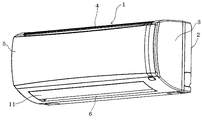
1はセパレート式空気調和機の室内機で、背面板2と前方の前面カバー3によって筐体を形成し、前記前面カバー3の上面中央には横長スリット状の吸込口4を有している。前記前面カバー3の前面中央にはオープンパネル5を備え、このオープンパネル5上部左右に設けた軸(図示せず)を支点として前面カバー3前方へ開閉自在に取付られる。前記前面カバー3底面には横長の吹出口6を設け、前記吸込口4から吸い込まれた室内の空気は室内機1内部で温度調節され吹出口6から吹き出される。
Next, an embodiment of the air conditioner of the present invention will be described with reference to the drawings.
Reference numeral 1 denotes an indoor unit of a separate type air conditioner, in which a housing is formed by a
前記吸込口4と吹出口6の間には横長で多段に屈曲されたフィンチューブ式の室内熱交換器7を設け、この室内熱交換器7の下流側にはクロスフロー式の室内送風ファン8を配置している。この送風ファン8は通常運転時約600〜1,400rpmの早さで回転し、前記吸込口4から室内空気を吸い込み吹出口6より熱交換された空気を吹き出すものである。前記室内熱交換器8の下方には樹脂の発泡材で一体成形されたドレーン皿(図示せず)を設け、結露水を受けると共に室内送風ファン8の送風を吹出口6へ導くエアーガイドの機能を兼ねる。また、前記吸込口4から吹出口6の間には室内送風経路9を形成し、この送風経路9の吸込口4内側には、吸込空気内に混在するゴミを取り除くエアフィルタ(図示せず)を有する。
A fin tube type
10は前記室内送風ファン8を駆動する室内送風モーターで、室内制御部10からの指令に応じて任意に回転数を可変可能なDCモーター等で構成し、この実施例では600rpm(B1)、800rpm(B2)、1,000rpm(B2)、1,200rpm(B4)、1,400rpm(B5)の5段階の回転速度を設定している。
前記吹出口6には運転時に上下方向の吹出風の風向を調整すると共に、停止時には自動的に吹出口6を閉じる水平ルーバー11備え、この水平ルーバー11の両端には駆動軸12を有し、この駆動軸12に接続したルーバモーター13によって前記水平ルーバー11を回動する。前記ルーバーモーター13はステップモーターで構成し、図6で示すように、水平ルーバー11は運転停止位置C0(吹出口6を水平ルーバー11で閉じる位置)を基準角度としてC1からC6の所定角度まで開く方向に段階的に回動する。
The
14は室内熱交センサで、前記室内熱交換器7の表面や室内熱交換器7の入口や出口の近傍に接続された冷媒配管15の温度を検知して、通常の暖房運転起動時に吹出口6から冷たい風が吹き出して使用者が肌寒く不快に感じることを防止するために、室内熱交センサ14の温度の上昇具合に応じて送風ファン8の始動タイミングや回転数を室内制御部16にて制御調整する。17は室温センサで、前記吸込口4の近傍の室内送風経路9に取り付けられ吸込口4から吸い込まれて室内空気の温度を検知する。
18は室外機で、内部に圧縮機19、室外熱交換器20、冷媒の流路を切り替える四方弁21、冷媒を減圧する膨張弁22を有し、前記圧縮機19、四方弁21、室内熱交換器7、膨張弁22、室外熱交換器20、四方弁21を冷媒配管15で順次接続して冷凍回路23を形成する。
前記圧縮機19は、インバータにより回転数が制御されるモーター(図示せず)によって駆動されることで、運転能力を20rpsから100rpsの間で可変できる能力可変型圧縮機である。前記室外熱交換器20は、フィンチューブ式の熱交換器で風下側に配置された室外送風ファン23によって外気を送風することで熱交換を行う。この室外送風ファン23はプロペラファンで構成され、室外送風モーター24によって回転駆動する。前記四方弁21は冷凍回路15に流れる冷媒の方向を切り替えることで、暖房運転と冷房運転とを切り替えるものであり、暖房運転では図2で示す実線矢印の方向に、冷房運転では破線矢印の方向に冷媒の流れる方向を切り替える。前記膨張弁22は電子式の膨張弁で、室外制御部25からの開度指令に応じて開度を自由に調整する。26は外気温センサで室外の温度を検知して室外制御部25に定期的に通知する。27は室外熱交センサで、前記室外熱交換器20の表面や、室外熱交換器20の入口や出口の近傍に接続された冷媒配管15の温度を検知することで、暖房運転時の着霜の状態を室外制御部25にて把握して除霜運転を行う。
The
28はリモコンで、前記室内機1の室内制御部16に対して、運転信号を発するもので、液晶画面に各種の運転条件やタイマー時間等の表示を行う表示部29と、運転操作を行う操作部30を有している。この操作部30には運転・停止を行う運転スイッチ31、暖房運転・冷房運転・ドライ運転等の運転モードを設定する運転モードスイッチ32、室温の設定を行う室温設定スイッチ33、タイマ運転の設定を行うタイマースイッチ34、衣類乾燥モードの選択を行う衣類乾燥スイッチ35、水平ルーバー11の吹出方向の変更やスイングモードの選択を行うルーバースイッチ36等、多数のボタンスイッチを有している。
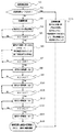
次に図3〜6を基に暖房運転開始時の作動について説明すれば、S1にてリモコン28の運転スイッチ31を押圧して空気調和機の運転を開始する。前回の運転が暖房運転であったことを前提として暖房運転が開始される。次に、S2に進んで衣類乾燥モードがONかを判定する。衣類乾燥モードはリモコン28の衣類乾燥スイッチ35によって選択される。衣類乾燥モードでの運転は洗濯物乾燥が最優先されるもので、衣類乾燥モード中は室内が無人であることを想定しているので、室内の快適性は考慮しない。
Next, the operation at the start of the heating operation will be described with reference to FIGS. 3 to 6. In S1, the
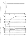
S2に於いて「No」であればS3に進み通常の暖房運転を行い、S2で「Yes」であればS16に進み暖房運転における衣類乾燥運転を開始する。まず、通常の暖房運転から説明すれば、S3で圧縮機19が始動する、この圧縮機19の回転数は室温設定スイッチ32で設定された室温の設定値と室温センサ17が検知する室温との温度差によって決定するが、暖房運転の開始時には温度差は大きいので最高回転数の100rpsをめざして除々に上昇する。約2分ほどを費やして最高回転数に達する。このことは、圧縮機19の回転速度は冷凍サイクル内の冷凍機油が混在する冷媒が回転速度に追従するために回転数の変動速度に規制が設けられているためである。
If "No" in S2, the process proceeds to S3 to perform the normal heating operation, and if "Yes" in S2, the process proceeds to S16 to start the clothes drying operation in the heating operation. First, from the normal heating operation, the
次にS4に進んで室内熱交センサ14の読込を開始する。圧縮機19が回転しているので室内熱交センサ14も徐々に上昇する。そして、S5にて室内熱交センサ14の温度(A)が28℃(A1)を越えたかを判断し、越えた場合に室内送風ファン8を600rpm(B1)で始動し、水平ルーバー11を前回運転時の角度に回動して吹出口6を開口する。これにより、室内熱交換器7の温度が十分に上昇する前に室内送風ファン8の運転が行われることで生じる冷風の吹出しを防止し、暖房運転開始時の快適性を向上させている。また、前回の運転がスイング運転である場合には水平ルーバ11はC1からC5の角度の間を揺動するが、C5の位置では約6秒間一時停止し揺動を繰り返す。これにより、吹き出す温風を比較的下方向に重点的に吹き出すことで温風を効率的に室内に循環して快適性を向上する。
Next, the process proceeds to S4 to start reading the indoor
次に、S7では室内熱交センサ14の温度(A)が更に上昇し29.5℃(A2)を越えたかを判断する。越えた場合に室内送風ファン8を800rpm(B2)に上昇する。(S8)これによって、室内の使用者に冷風感を与えずに室内送風ファン8の回転数を徐々に上昇することができる。
Next, in S7, it is determined whether the temperature (A) of the indoor
次に、S9では室内熱交センサ14の温度(A)が更に上昇し31.5℃(A3)を越えたかを判断する。越えた場合に室内送風ファン8を1,000rpm(B3)に上昇する。(S10)
Next, in S9, it is determined whether the temperature (A) of the indoor
次に、S11では室内熱交センサ14の温度(A)が更に上昇し34℃(A4)を越えたかを判断する。越えた場合に室内送風ファン8を1,200rpm(B4)に上昇する。(S12)
Next, in S11, it is determined whether the temperature (A) of the indoor
次に、S13では室内熱交センサ14の温度(A)が更に上昇し40℃(A5)を越えたかを判断する。越えた場合に室内送風ファン8を1,400rpm(B4)に上昇する。(S12)このようにS9からS14では、S7とS8と同様の動作を繰り返し室内送風ファン8が最高回転数である1,400rpm(B5)に到達することで空気調和機は最高出力を発揮する。これによって、室内の使用者に冷風感を与えずに室内送風ファン8の回転数を徐々に上昇し、最高回転数に到達することができる。
Next, in S13, it is determined whether the temperature (A) of the indoor
次に、暖房運転開始(S1)から最高出力(S14)に到達するまで十数分間を要しているが、S15に於いて最高出力を継続し室温が設定室温まで上昇すれば、現在の室温に応じて圧縮機19や室内送風ファン8の回転数下がり適正な暖房出力で運転する。
Next, it takes more than ten minutes from the start of heating operation (S1) to the maximum output (S14), but if the maximum output is continued in S15 and the room temperature rises to the set room temperature, the current room temperature The number of revolutions of the
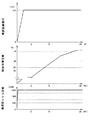
S2で「Yes」であればS16に進み暖房運転における衣類乾燥運転を開始する。S16の衣類乾燥運転では、室内熱交温度Aに係わらず、圧縮機19と室内送風ファン8を共に最高回転数近傍の所定回転数を目指して始動する。水平ルーバ11は洗濯物が下方向に配置されることを想定して、通常の暖房運転での水平ルーバ11での下限位置であるC5よりも下側のC6の位置に回動する。これにより、洗濯物に積極的送風して洗濯物の周囲の湿度を下げることで洗濯物の乾燥をより早くすることができる。また、前回の運転がスイング運転である場合には水平ルーバ11はC1からC6の角度の間を揺動するが、C5の位置では一時停止しせずに揺動を繰り返す。これにより、室内の空気の撹拌をより効率的に行うことで洗濯物の乾燥を更に早くすることができる。
If "Yes" in S2, the process proceeds to S16 to start the clothes drying operation in the heating operation. In the clothes drying operation of S16, both the
次にS15に於いて最高出力を継続し室温が設定室温まで上昇すれば、現在の室温に応じて圧縮機19や室内送風ファン8の回転数下がり適正な暖房出力で運転するが、水平ルーバ11の角度C6や揺動範囲(C1〜C6)はかわらずに継続する。これにより、室内の空気の撹拌をより効率的に行うことで洗濯物の乾燥を更に早くすることができる。
Next, if the maximum output is continued in S15 and the room temperature rises to the set room temperature, the rotation speed of the
このように、洗濯物を乾燥する衣類乾燥モードが選択された場合には、暖房運転開始時に圧縮機19を起動すると共に、強制的に室内送風ファン8を最高回転数近傍の所定回転数で始動することで、洗濯物の乾燥時間の短縮を最優先にして、乾燥時間を短縮することができる。また、衣類乾燥モードが選択された場合には、水平ルーバー11の可動範囲を、通常の暖房運転時の可動範囲よりも下方向に大きく設定することで、乾燥時間を更に短縮することができる。また、水平ルーバー11を揺動するスイングモード選択時で、かつ衣類乾燥モードが選択された場合には、水平ルーバー11の揺動範囲を、通常の暖房運転時の揺動範囲よりも下方向に大きく設定することで、乾燥時間を更に短縮することができる。また、通常暖房運転時のスイングモードは、水平ルーバー11が下方向の最端位置で所定時間停止後に一定周期で揺動し、衣類乾燥モードでの運転時にはスイングモードは、水平ルーバー11の下方向の最端位置で停止せずに一定周期で揺動することで、乾燥時間を更に短縮することができる。
In this way, when the clothes drying mode for drying the laundry is selected, the
この発明の実施形態を説明したが、これらの実施形態は、例として提示したものであり、発明の範囲を限定することは意図していない。これら新規な実施形態は、その他の様々な形態で実施されることが可能であり、発明の要旨を逸脱しない範囲で、種々の省略、置き換え、変更を行うことができる。これら実施形態やその変形は、発明の範囲や要旨に含まれるとともに、特許請求の範囲に記載された発明とその均等の範囲に含まれる。 Although embodiments of the present invention have been described, these embodiments are presented as examples and are not intended to limit the scope of the invention. These novel embodiments can be implemented in various other embodiments, and various omissions, replacements, and changes can be made without departing from the gist of the invention. These embodiments and modifications thereof are included in the scope and gist of the invention, and are also included in the scope of the invention described in the claims and the equivalent scope thereof.
例えば、S16における水平ルーバ11の位置をC6としたが、C6ではなくて前回運転時の水平ルーバ11の角度にしても良い。
For example, although the position of the
また、衣類乾燥モードに最大時間や設定時間を設けて、時間の満了後には自動で通常の暖房運転に移行するようにしても良い。 Further, a maximum time or a set time may be set in the clothes drying mode, and after the time expires, the normal heating operation may be automatically performed.
1 室内機
2 前面カバー
6 吹出口
7 室内熱交換器
8 室内送風ファン
10 室内送風モーター
11 水平ルーバー
13 ルーバモーター
14 室内熱交センサ
16 室内制御部
19 圧縮機
27 リモコン
31 運転モードスイッチ
34 衣類乾燥スイッチ
35 ルーバースイッチ
1
Claims (1)
室内熱交換器と、室内送風ファンと、上下方向の風向を可変する水平ルーバーとを備えた室内機と、
前記室内熱交換器の温度を検出する室内熱交センサと、
前記室外機と室内機を制御する制御手段と、
運転操作を行う操作部とを備え、
前記制御手段は、暖房運転開始時に前記圧縮機を起動すると共に、前記室内熱交センサの検知を開始し、
前記圧縮機を起動した後、前記室内熱交センサの検出値が所定温度以上となったら、前記室内送風ファンの回転を開始する空気調和機に於いて、
前記操作部にて洗濯物の乾燥運転を選択する衣類乾燥モードを有し、
前記衣類乾燥モードが選択された場合には、暖房運転開始時に前記圧縮機を起動すると共に、強制的に前記室内送風ファンを所定回転で始動する制御手段を備え、
前記水平ルーバーを揺動するスイングモードを有し、
前記スイングモード選択時で、かつ前記暖房運転が選択された場合は、前記水平ルーバーが下方向の最端位置で所定時間停止後に一定周期で揺動し、
前記スイングモード選択時で、かつ前記衣類乾燥モードが選択された場合には、水平ルーバーが下方向の最端位置で停止せず、一定周期で揺動することを特徴とする空気調和機。 A compressor, an outdoor heat exchanger, an outdoor blower fan, an outdoor unit equipped with an expansion valve,
An indoor unit equipped with an indoor heat exchanger, an indoor blower fan, and a horizontal louver that changes the wind direction in the vertical direction.
An indoor heat exchange sensor that detects the temperature of the indoor heat exchanger,
A control means for controlling the outdoor unit and the indoor unit ,
And an operating unit that performs the luck rolling operation,
The control means starts the compressor at the start of the heating operation and starts the detection of the indoor heat exchange sensor.
In the air conditioner that starts the rotation of the indoor blower fan when the detected value of the indoor heat exchange sensor reaches a predetermined temperature or higher after starting the compressor.
The operation unit has a clothes drying mode for selecting a laundry drying operation.
When the clothes drying mode is selected, the compressor is started at the start of the heating operation, and a control means for forcibly starting the indoor blower fan at a predetermined rotation is provided.
It has a swing mode that swings the horizontal louver, and has a swing mode.
When the swing mode is selected and the heating operation is selected, the horizontal louver swings at a fixed period after stopping at the lowermost position for a predetermined time.
An air conditioner characterized in that when the swing mode is selected and the clothes drying mode is selected, the horizontal louver does not stop at the lowermost position and swings at a constant cycle.
Priority Applications (1)
| Application Number | Priority Date | Filing Date | Title |
|---|---|---|---|
| JP2017024161A JP6932002B2 (en) | 2017-02-13 | 2017-02-13 | Air conditioner |
Applications Claiming Priority (1)
| Application Number | Priority Date | Filing Date | Title |
|---|---|---|---|
| JP2017024161A JP6932002B2 (en) | 2017-02-13 | 2017-02-13 | Air conditioner |
Publications (3)
| Publication Number | Publication Date |
|---|---|
| JP2018132210A JP2018132210A (en) | 2018-08-23 |
| JP2018132210A5 JP2018132210A5 (en) | 2019-08-22 |
| JP6932002B2 true JP6932002B2 (en) | 2021-09-08 |
Family
ID=63249532
Family Applications (1)
| Application Number | Title | Priority Date | Filing Date |
|---|---|---|---|
| JP2017024161A Active JP6932002B2 (en) | 2017-02-13 | 2017-02-13 | Air conditioner |
Country Status (1)
| Country | Link |
|---|---|
| JP (1) | JP6932002B2 (en) |
Families Citing this family (1)
| Publication number | Priority date | Publication date | Assignee | Title |
|---|---|---|---|---|
| CN111197844A (en) * | 2018-11-19 | 2020-05-26 | 青岛海尔空调器有限总公司 | Micro air conditioner and control method thereof |
-
2017
- 2017-02-13 JP JP2017024161A patent/JP6932002B2/en active Active
Also Published As
| Publication number | Publication date |
|---|---|
| JP2018132210A (en) | 2018-08-23 |
Similar Documents
| Publication | Publication Date | Title |
|---|---|---|
| JP6185251B2 (en) | Air conditioner | |
| CN111356881B (en) | Air conditioner and control method thereof | |
| TW201839324A (en) | air conditioner | |
| JP6498598B2 (en) | Control device, air conditioning system including the same, and control method | |
| JP6401585B2 (en) | Air conditioner | |
| JP5241935B2 (en) | Dehumidifier | |
| JP2019060526A (en) | Air conditioner | |
| JP6932002B2 (en) | Air conditioner | |
| JP4231247B2 (en) | Air conditioner | |
| JP4548979B2 (en) | Air conditioner | |
| KR100561136B1 (en) | Air conditioner | |
| JP3105276B2 (en) | Air conditioner | |
| JP2010078254A (en) | Air conditioner | |
| JP4619983B2 (en) | Air conditioner | |
| JP4999490B2 (en) | Dehumidifier | |
| JP6584358B2 (en) | Dehumidifying and drying equipment | |
| JPH10103739A (en) | Air conditioner | |
| JP4381008B2 (en) | Air conditioner | |
| JPWO2018134888A1 (en) | Air conditioner | |
| JP2018132210A5 (en) | ||
| JP3281201B2 (en) | Air conditioner | |
| JPH11248231A (en) | Air-conditioner | |
| JP7132097B2 (en) | Dehumidifier with drying function | |
| CN112752930A (en) | Air conditioner | |
| JP4614748B2 (en) | Air conditioner |
Legal Events
| Date | Code | Title | Description |
|---|---|---|---|
| A521 | Written amendment |
Free format text: JAPANESE INTERMEDIATE CODE: A523 Effective date: 20190712 |
|
| A621 | Written request for application examination |
Free format text: JAPANESE INTERMEDIATE CODE: A621 Effective date: 20190712 |
|
| A621 | Written request for application examination |
Free format text: JAPANESE INTERMEDIATE CODE: A621 Effective date: 20190712 |
|
| A977 | Report on retrieval |
Free format text: JAPANESE INTERMEDIATE CODE: A971007 Effective date: 20200604 |
|
| A131 | Notification of reasons for refusal |
Free format text: JAPANESE INTERMEDIATE CODE: A131 Effective date: 20200616 |
|
| A521 | Written amendment |
Free format text: JAPANESE INTERMEDIATE CODE: A523 Effective date: 20200803 |
|
| A131 | Notification of reasons for refusal |
Free format text: JAPANESE INTERMEDIATE CODE: A131 Effective date: 20210126 |
|
| A521 | Written amendment |
Free format text: JAPANESE INTERMEDIATE CODE: A523 Effective date: 20210205 |
|
| TRDD | Decision of grant or rejection written | ||
| A01 | Written decision to grant a patent or to grant a registration (utility model) |
Free format text: JAPANESE INTERMEDIATE CODE: A01 Effective date: 20210810 |
|
| A61 | First payment of annual fees (during grant procedure) |
Free format text: JAPANESE INTERMEDIATE CODE: A61 Effective date: 20210817 |
|
| R150 | Certificate of patent or registration of utility model |
Ref document number: 6932002 Country of ref document: JP Free format text: JAPANESE INTERMEDIATE CODE: R150 |