JP6931484B2 - Electric power steering device - Google Patents

Electric power steering device Download PDF

Info

Publication number
JP6931484B2
JP6931484B2 JP2017156370A JP2017156370A JP6931484B2 JP 6931484 B2 JP6931484 B2 JP 6931484B2 JP 2017156370 A JP2017156370 A JP 2017156370A JP 2017156370 A JP2017156370 A JP 2017156370A JP 6931484 B2 JP6931484 B2 JP 6931484B2
Authority
JP
Japan
Prior art keywords
steering
unit
command value
value
angular velocity
Prior art date
Legal status (The legal status is an assumption and is not a legal conclusion. Google has not performed a legal analysis and makes no representation as to the accuracy of the status listed.)
Active
Application number
JP2017156370A
Other languages
Japanese (ja)
Other versions
JP2019034616A (en
Inventor
貴弘 椿
貴弘 椿
Current Assignee (The listed assignees may be inaccurate. Google has not performed a legal analysis and makes no representation or warranty as to the accuracy of the list.)
NSK Ltd
Original Assignee
NSK Ltd
Priority date (The priority date is an assumption and is not a legal conclusion. Google has not performed a legal analysis and makes no representation as to the accuracy of the date listed.)
Filing date
Publication date
Application filed by NSK Ltd filed Critical NSK Ltd
Priority to JP2017156370A priority Critical patent/JP6931484B2/en
Publication of JP2019034616A publication Critical patent/JP2019034616A/en
Application granted granted Critical
Publication of JP6931484B2 publication Critical patent/JP6931484B2/en
Active legal-status Critical Current
Anticipated expiration legal-status Critical

Links

Images

Landscapes

  • Steering Control In Accordance With Driving Conditions (AREA)
  • Control Of Driving Devices And Active Controlling Of Vehicle (AREA)

Description

本発明は、電流指令値に基づくモータの駆動制御によって操舵系に対してアシスト制御及び舵角制御を行うことにより、自動操舵も可能とする電動パワーステアリング装置に関し、特に自動操舵中に運転者により操舵介入が行われても、安全で且つ違和感の低減が可能な電動パワーステアリング装置に関する。 The present invention relates to an electric power steering device that enables automatic steering by performing assist control and steering angle control on the steering system by driving control of a motor based on a current command value, and particularly by a driver during automatic steering. The present invention relates to an electric power steering device that is safe and can reduce discomfort even when steering intervention is performed.

車両の操舵系にモータの回転力で操舵補助力(アシストトルク)を付与する電動パワーステアリング装置(EPS)は、モータの駆動力を、減速機構を介してギア又はベルト等の伝達機構により、ステアリングシャフト或いはラック軸に操舵補助力として付与し、アシスト制御するようになっている。かかる従来の電動パワーステアリング装置は、アシストトルクを正確に発生させるため、モータ電流のフィードバック制御を行っている。フィードバック制御は、操舵補助指令値(電流指令値)とモータ電流検出値との差が小さくなるようにモータ印加電圧を調整するものであり、モータ印加電圧の調整は、一般的にPWM(パルス幅変調)制御のデューティの調整で行っている。 The electric power steering device (EPS), which applies steering assist force (assist torque) to the steering system of the vehicle by the rotational force of the motor, steers the driving force of the motor by a transmission mechanism such as a gear or a belt via a reduction mechanism. It is applied to the shaft or rack shaft as a steering assist force for assist control. In such a conventional electric power steering device, feedback control of the motor current is performed in order to accurately generate the assist torque. Feedback control adjusts the motor applied voltage so that the difference between the steering assist command value (current command value) and the motor current detection value becomes small, and the adjustment of the motor applied voltage is generally PWM (pulse width). Modulation) Control duty is adjusted.

電動パワーステアリング装置の一般的な構成を図1に示して説明すると、ハンドル1のコラム軸(ステアリングシャフト、ハンドル軸)2は減速機構を構成する減速ギア(ウォームギア)3、ユニバーサルジョイント4a及び4b、ピニオンラック機構5、タイロッド6a,6bを経て、更にハブユニット7a,7bを介して操向車輪8L,8Rに連結されている。また、コラム軸2にはトーションバーが介挿されており、トーションバーの捩れ角によりハンドル1の操舵角θを検出する舵角センサ14、操舵トルクTtを検出するトルクセンサ10が設けられており、ハンドル1の操舵力を補助するモータ20が減速ギア3を介してコラム軸2に連結されている。電動パワーステアリング装置を制御するコントロールユニット(ECU)30には、バッテリ13から電力が供給されると共に、イグニションキー11を経てイグニションキー信号が入力される。コントロールユニット30は、トルクセンサ10で検出された操舵トルクTtと車速センサ12で検出された車速Vとに基づいてアシスト制御指令の電流指令値の演算を行い、電流指令値に補償等を施した電圧制御指令値Vrefによってモータ20に供給する電流を制御する。 The general configuration of the electric power steering device will be described with reference to FIG. 1. The column shafts (steering shaft, steering wheel shaft) 2 of the steering wheel 1 are reduction gears (worm gears) 3, universal joints 4a and 4b, which form a reduction mechanism. It is connected to the steering wheels 8L and 8R via the pinion rack mechanism 5, the tie rods 6a and 6b, and further via the hub units 7a and 7b. Further, a torsion bar is inserted in the column shaft 2, and a steering angle sensor 14 for detecting the steering angle θ of the steering wheel 1 and a torque sensor 10 for detecting the steering torque Tt are provided. The motor 20 that assists the steering force of the steering wheel 1 is connected to the column shaft 2 via the reduction gear 3. Power is supplied from the battery 13 to the control unit (ECU) 30 that controls the electric power steering device, and an ignition key signal is input via the ignition key 11. The control unit 30 calculates the current command value of the assist control command based on the steering torque Tt detected by the torque sensor 10 and the vehicle speed V detected by the vehicle speed sensor 12, and compensates the current command value. The current supplied to the motor 20 is controlled by the voltage control command value Vref.

なお、舵角センサ14は必須のものではなく、配設されていなくても良く、また、モータ20に連結されたレゾルバ等の回転角センサから操舵角を取得することも可能である。 The steering angle sensor 14 is not essential and does not have to be arranged, and it is also possible to acquire the steering angle from a rotation angle sensor such as a resolver connected to the motor 20.

コントロールユニット30には、車両の各種情報を授受するCAN(Controller Area Network)40が接続されており、車速VはCAN40から受信することも可能である。また、コントロールユニット30には、CAN40以外の通信、アナログ/ディジタル信号、電波等を授受する非CAN41も接続可能である。 A CAN (Controller Area Network) 40 for exchanging various information about the vehicle is connected to the control unit 30, and the vehicle speed V can be received from the CAN 40. Further, a non-CAN 41 that transmits / receives communications other than the CAN 40, analog / digital signals, radio waves, and the like can also be connected to the control unit 30.

コントロールユニット30は主としてCPU(MPUやMCU等も含む)で構成されるが、そのCPU内部においてプログラムで実行される一般的な機能を示すと図2のようになる。 The control unit 30 is mainly composed of a CPU (including an MPU, MCU, etc.), and FIG. 2 shows a general function executed by a program inside the CPU.

図2を参照してコントロールユニット30を説明すると、トルクセンサ10で検出された操舵トルクTt及び車速センサ12で検出された(若しくはCAN40からの)車速Vは、電流指令値Iref1を演算する電流指令値演算部31に入力される。電流指令値演算部31は、入力された操舵トルクTt及び車速Vに基づいてアシストマップ等を用いて、モータ20に供給する電流の制御目標値である電流指令値Iref1を演算する。電流指令値Iref1は加算部32Aを経て電流制限部33に入力され、最大電流を制限された電流指令値Irefmが減算部32Bに入力され、フィードバックされているモータ電流Imとの偏差I(=Irefm−Im)が演算され、その偏差Iが操舵動作の特性改善のためのPI(比例積分)制御部35に入力される。PI制御部35で特性改善された電圧制御指令値VrefがPWM制御部36に入力され、更にインバータ37を介してモータ20がPWM駆動される。モータ20のモータ電流Imはモータ電流検出器38で検出され、減算部32Bにフィードバックされる。インバータ37は、半導体スイッチング素子としてのFETのブリッジ回路で構成されている。 Explaining the control unit 30 with reference to FIG. 2, the steering torque Tt detected by the torque sensor 10 and the vehicle speed V detected by the vehicle speed sensor 12 (or from the CAN 40) are current commands for calculating the current command value Iref1. It is input to the value calculation unit 31. The current command value calculation unit 31 calculates the current command value Iref1, which is the control target value of the current supplied to the motor 20, by using the assist map or the like based on the input steering torque Tt and the vehicle speed V. The current command value Iref1 is input to the current limiting unit 33 via the adding unit 32A, the current command value Ireffm whose maximum current is limited is input to the subtracting unit 32B, and the deviation I (= Ireff) from the fed-back motor current Im. −Im) is calculated, and the deviation I is input to the PI (proportional integration) control unit 35 for improving the characteristics of the steering operation. The voltage control command value Vref whose characteristics have been improved by the PI control unit 35 is input to the PWM control unit 36, and the motor 20 is PWM-driven via the inverter 37. The motor current Im of the motor 20 is detected by the motor current detector 38 and fed back to the subtraction unit 32B. The inverter 37 is composed of a bridge circuit of FET as a semiconductor switching element.

モータ20にはレゾルバ等の回転角センサ21が連結されており、回転角センサ21から回転角θが検出されて出力される。 A rotation angle sensor 21 such as a resolver is connected to the motor 20, and the rotation angle θ is detected and output from the rotation angle sensor 21.

また、加算部32Aには補償信号生成部34からの補償信号CMが加算されており、補償信号CMの加算によって操舵システム系の特性補償を行い、収れん性や慣性特性等を改善するようになっている。補償信号生成部34は、セルフアライニングトルク(SAT)34Cと慣性34Bを加算部34Dで加算し、その加算結果に更に収れん性34Aを加算部34Eで加算し、加算部34Eの加算結果を補償信号CMとしている。 Further, the compensation signal CM from the compensation signal generation unit 34 is added to the addition unit 32A, and the characteristics of the steering system system are compensated by adding the compensation signal CM to improve the astringency, the inertial characteristics, and the like. ing. The compensation signal generation unit 34 adds the self-aligning torque (SAT) 34C and the inertia 34B by the addition unit 34D, further adds the convergence 34A to the addition result by the addition unit 34E, and compensates the addition result of the addition unit 34E. It is a signal CM.

近年、車両の自動運転技術の研究開発が進められており、その中の自動操舵において、電動パワーステアリング装置(EPS)を応用する提案がなされている。EPSにより自動操舵を実現する場合、従来のEPSが実行しているアシスト制御のための機構と、車両が所望の方向に走行するように操舵系を制御する舵角制御のための機構を独立して保有し、これらの出力を調整可能とする構成が一般的となっている。また、舵角制御では、操舵角の制御目標である舵角指令に対する応答性及び路面反力等に対する外乱抑圧性で優れた性能をもつ位置速度制御が用いられており、例えば、位置制御ではP(比例)制御、速度制御ではPI(比例積分)制御が採用されている。 In recent years, research and development of automatic driving technology for vehicles has been promoted, and it has been proposed to apply an electric power steering device (EPS) in the automatic steering thereof. When automatic steering is realized by EPS, the mechanism for assist control executed by the conventional EPS and the mechanism for steering angle control that controls the steering system so that the vehicle travels in a desired direction are independent. It is common to have a configuration in which these outputs can be adjusted. Further, in the rudder angle control, position speed control having excellent performance in response to a rudder angle command, which is a control target of the steering angle, and disturbance suppression property against a road surface reaction force, etc. is used. PI (proportional integration) control is adopted for (proportional) control and speed control.

アシスト制御と舵角制御を独立して実行し、双方からの出力である指令値を切り換えて全体の制御を行う場合、スイッチ等により急に切り換えてしまうと、指令値が急変動し、ハンドル挙動が不自然になり、運転者へ違和感を与えるおそれがある。特開2004−17881号公報(特許文献1)では、この問題への対応として、トルク制御方式(アシスト制御に相当)と回転角制御方式(舵角制御に相当)の切り換えにおいて、双方からの指令値それぞれに係数(自動化係数及び手動化係数)を乗算して加算した値を最終指令値とし、この係数を徐々に変化させることにより、指令値の急変動を抑制するようにしている。また、回転角制御方式での位置制御ではP制御、速度制御ではPI制御を使用している。 When assist control and steering angle control are executed independently and the command value that is the output from both is switched to perform overall control, if the command value is suddenly switched by a switch or the like, the command value suddenly fluctuates and the handle behavior. May become unnatural and give the driver a sense of discomfort. In Japanese Patent Application Laid-Open No. 2004-17881 (Patent Document 1), as a response to this problem, commands are given from both sides in switching between the torque control method (corresponding to assist control) and the rotation angle control method (corresponding to steering angle control). The final command value is a value obtained by multiplying each value by a coefficient (automation coefficient and manualization coefficient) and adding them, and by gradually changing this coefficient, sudden fluctuations in the command value are suppressed. Further, P control is used for position control in the rotation angle control method, and PI control is used for speed control.

特許第3917008号公報(特許文献2)では、設定操舵角に従ってハンド操作を自動で行い、特に駐車支援を目的とした自動操舵制御装置が提案されている。この装置では、トルク制御モード(アシスト制御に相当)と駐車支援モード(舵角制御に相当)が切り換えられるようになっており、駐車支援モードでは、予め記憶された駐車データを使用して制御を行っている。そして、駐車支援モードでの位置制御ではP制御、速度制御ではPI制御を行っている。 Japanese Patent No. 3917008 (Patent Document 2) proposes an automatic steering control device that automatically performs a hand operation according to a set steering angle, and particularly for the purpose of parking assistance. In this device, the torque control mode (corresponding to assist control) and the parking support mode (corresponding to steering angle control) can be switched. In the parking support mode, control is performed using the parking data stored in advance. Is going. Then, P control is performed in the position control in the parking support mode, and PI control is performed in the speed control.

特許第3912279号公報(特許文献3)はEPSを直接応用したものではないが、自動操舵モードへの切り換えにより舵角制御を開始する際に、操舵速度(舵角速度)を緩やかに増加させることにより、開始時のハンドル急変動による運転者への違和感を低減している。 Japanese Patent No. 391279 (Patent Document 3) does not directly apply EPS, but by gradually increasing the steering speed (steering angular velocity) when starting steering angle control by switching to the automatic steering mode. , The driver feels uncomfortable due to sudden changes in the steering wheel at the start.

特開2004−17881号公報Japanese Unexamined Patent Publication No. 2004-17881 特許第3917008号公報Japanese Patent No. 3917008 特許第3912279号公報Japanese Patent No. 391279

しかしながら、特許文献1では、方式の切り換え中は舵角制御に対する指令値(舵角制御指令値)が係数により制限されて最終指令値に出力されるので、制限された分だけ最終指令値が小さくなってしまう。この制限により、舵角制御指令値から算出される舵角速度に対する指令値(舵角速度指令値)に対して、モータの実速度が遅くなってしまうので、舵角速度指令値と実速度の間に偏差が発生し、速度制御内のI(積分)制御の積分値が蓄積しまうことになり、速度制御から更に大きな舵角制御指令値が出力されてしまうことになる。この結果、アシスト制御に対する指令値(アシスト制御指令値)に乗算する係数が徐々に大きくなっていく状態では、係数による制限が緩和されていくので、係数が大きくなるに従って舵角制御指令値が過剰な値となり、ハンドルが舵角速度指令値に対して過剰に反応し、引っ掛かり感等の違和感や不快感を運転者に与えるおそれがある。 However, in Patent Document 1, since the command value (rudder angle control command value) for steering angle control is limited by the coefficient and output to the final command value during the switching of the method, the final command value is reduced by the limited amount. turn into. Due to this limitation, the actual speed of the motor becomes slower than the command value for the steering angular velocity (rudder angular velocity command value) calculated from the steering angular velocity control command value, so there is a deviation between the steering angular velocity command value and the actual speed. Will occur, and the integrated value of the I (integration) control in the speed control will be accumulated, and a larger steering angle control command value will be output from the speed control. As a result, in a state where the coefficient to be multiplied by the command value for assist control (assist control command value) gradually increases, the restriction by the coefficient is relaxed, so that the steering angle control command value becomes excessive as the coefficient increases. There is a risk that the steering wheel will react excessively to the steering angle speed command value, giving the driver a sense of discomfort or discomfort such as a feeling of being caught.

また、特許文献1では、位置制御にP制御、速度制御にPI制御を使用しており、舵角制御中に運転者による手入力の介入があった場合、舵角制御は舵角制御指令値に追従するように動作するので、舵角制御からアシスト制御への切換動作が行われるまで、手動により操舵することが困難となる。また、手入力検出や切換動作により時間的な遅れが発生し、運転者による操舵介入の動作を十分に行うことができないおそれがある。 Further, in Patent Document 1, P control is used for position control and PI control is used for speed control, and when there is manual input intervention by the driver during rudder angle control, the rudder angle control is the rudder angle control command value. Since it operates so as to follow the steering angle, it becomes difficult to manually steer until the switching operation from the steering angle control to the assist control is performed. In addition, there is a possibility that a time delay may occur due to the manual input detection or the switching operation, and the driver may not be able to sufficiently perform the steering intervention operation.

特許文献2でも、位置制御にP制御、速度制御にPI制御を用いた舵角制御を行っている。車両において舵角制御を行う場合、車速、摩擦及び路面反力の変化等により外乱や負荷状況が大きく変化するため、装置は、それらに対して耐性がある制御構成でなければならない。しかし、特許文献2記載の装置の制御構成のみでは、例えば路面反力が変化した場合や、目標操舵角が素早く変化した場合に、ステアリングホイールのマスとトーションバーによるバネによる固有振動により振動が発生し、それを運転者が違和感や不快感として感じるおそれがある。 Patent Document 2 also performs steering angle control using P control for position control and PI control for speed control. When the steering angle is controlled in a vehicle, the disturbance and the load condition change greatly due to changes in vehicle speed, friction, road surface reaction force, etc., so the device must have a control configuration that is resistant to them. However, with only the control configuration of the device described in Patent Document 2, for example, when the road surface reaction force changes or the target steering angle changes quickly, vibration is generated by the natural vibration caused by the spring of the steering wheel mass and the torsion bar. However, the driver may feel discomfort or discomfort.

特許文献3では、舵角制御開始時に徐々に舵角速度を増加させているが、増加が始まると舵角速度の上限値に達するまで増加し続けるので、I制御の積分値が過剰に蓄積してしまう。その結果、舵角制御指令値が過剰な値となり、ハンドルが舵角速度指令値に対して過剰に反応し、運転者に違和感を与えてしまうおそれがある。 In Patent Document 3, the rudder angular velocity is gradually increased at the start of the rudder angular velocity, but when the increase starts, it continues to increase until the upper limit of the rudder angular velocity is reached, so that the integrated value of the I control is excessively accumulated. .. As a result, the steering angle control command value becomes an excessive value, and the steering wheel may excessively react to the steering angular velocity command value, giving the driver a sense of discomfort.

本発明は上述のような事情よりなされたものであり、本発明の目的は、自動操舵中に運転者により操舵介入が行われても手動操舵を実現し、運転者による緊急操舵時の安全性をより確保した、アシスト制御と舵角制御を両立した電動パワーステアリング装置を提供することにある。また、自動操舵から手動操舵への切換時の引っ掛かり感等の運転者への違和感や不快感を低減する。 The present invention has been made based on the above circumstances, and an object of the present invention is to realize manual steering even if steering intervention is performed by the driver during automatic steering, and safety during emergency steering by the driver. The purpose of the present invention is to provide an electric power steering device that achieves both assist control and steering angle control. In addition, it reduces discomfort and discomfort to the driver such as a feeling of being caught when switching from automatic steering to manual steering.

本発明は、電流指令値に基づいてモータを駆動し、前記モータの駆動制御によって操舵系に対してアシスト制御及び舵角制御を行う電動パワーステアリング装置に関し、本発明の上記目的は、少なくとも目標操舵角及び実操舵角に基づいて、前記舵角制御のための舵角制御電流指令値を演算する舵角制御部と、手入力の判定に基づいて操舵状態を判定し、前記操舵状態に応じて、前記アシスト制御の制御量及び前記舵角制御の制御量を調整するための徐変ゲインを生成する切換判定/徐変ゲイン生成部と、前記アシスト制御のためのアシスト制御電流指令値を前記舵角制御電流指令値に加算して前記電流指令値を演算する加算部とを備え、前記切換判定/徐変ゲイン生成部は、前記目標操舵角に基づいて推定される推定操舵角と前記実操舵角の誤差に対して誤差閾値を用いて前記手入力の判定を行う第1判定部を具備する手入力判定部を備え、前記第1判定部が、特性が異なる複数の誤差用平滑化フィルタを有し、前記誤差用平滑化フィルタそれぞれで前記誤差を平滑化して複数の平滑化誤差を求め、前記平滑化誤差それぞれに対して前記誤差閾値を用いて前記手入力の判定を行うことにより達成される。 The present invention relates to an electric power steering device that drives a motor based on a current command value and controls the steering system by assist control and steering angle control by the drive control of the motor. The object of the present invention is at least target steering. The rudder angle control unit that calculates the rudder angle control current command value for the rudder angle control based on the angle and the actual steering angle, and the steering state is determined based on the manual input determination, and the steering state is determined according to the steering state. , The switching determination / gradual change gain generator for generating the control amount of the assist control and the gradual change gain for adjusting the control amount of the rudder angle control, and the assist control current command value for the assist control are set to the rudder. The switching determination / gradual change gain generation unit includes an addition unit that adds to the angle control current command value to calculate the current command value, and the switching determination / gradual change gain generation unit has an estimated steering angle estimated based on the target steering angle and the actual steering. A manual input determination unit including a first determination unit that determines the manual input using an error threshold for an angle error is provided, and the first determination unit provides a plurality of error smoothing filters having different characteristics. It is achieved by smoothing the error with each of the error smoothing filters to obtain a plurality of smoothing errors, and performing the manual input determination using the error threshold for each of the smoothing errors. NS.

本発明の上記目的は、前記第1判定部が、少なくとも1つの前記平滑化誤差に対して複数の前記誤差閾値を用い、手入力ありの判定結果として複数の判定結果を有することにより、或いは、前記手入力判定部が、操舵トルクに対してトルク閾値を用いて前記手入力の判定を行う第2判定部を更に具備することにより、或いは、前記第2判定部が、特性が異なる複数のトルク用平滑化フィルタを有し、前記トルク用平滑化フィルタそれぞれで前記操舵トルクを平滑化して複数の平滑化操舵トルクを求め、前記平滑化操舵トルクそれぞれに対して前記トルク閾値を用いて前記手入力の判定を行うことにより、或いは、前記第2判定部が、少なくとも1つの前記平滑化操舵トルクに対して複数の前記トルク閾値を用い、手入力ありの判定結果として複数の判定結果を有することにより、或いは、前記舵角制御部が、前記目標操舵角及び前記実操舵角に基づいて舵角速度指令値を演算する位置制御部と、前記舵角速度指令値に対して、前記操舵状態に応じて設定される制限値1によって制限をかけ、制限舵角速度指令値を出力する位置制御出力可変制限部と、前記制限舵角速度指令値及び実舵角速度に基づいて前記舵角制御電流指令値を演算する舵角速度制御部とを具備することにより、或いは、前記舵角制御部が、前記操舵トルク、舵角速度及び車速に応じて操舵介入補償のための補償舵角速度指令値を求める操舵介入補償部を更に具備し、前記補償舵角速度指令値を用いて前記制限舵角速度指令値を補償し、前記操舵介入補償部が、車速感応である基本マップを用いて前記操舵トルクから第1速度指令値を求める基本マップ部と、車速感応であるダンパゲインマップを用いて前記舵角速度に基づいて第2速度指令値を求めるダンパ演算部とを具備し、前記第1速度指令値及び前記第2速度指令値より前記補償舵角速度指令値を算出することにより、或いは、前記ダンパゲインマップが、前記車速が増加するとダンパゲインも増加する特性であることにより、或いは、前記操舵介入補償部が、前記基本マップ部の前段又は後段に、位相補償を行なう速度指令値位相補償部を更に具備し、前記基本マップ部及び前記速度指令値位相補償部を介して、前記操舵トルクから前記第1速度指令値を求めることにより、或いは、前記位置制御部が、前記目標操舵角と前記実操舵角の偏差に比例ゲインを乗算して前記舵角速度指令値を算出する比例ゲイン部を具備することにより、或いは、前記舵角速度制御部が、前記制限舵角速度指令値及び前記実舵角速度を用いて、I−P制御によって前記舵角制御電流指令値を演算することにより、或いは、前記切換判定/徐変ゲイン生成部が、動作モードをアシスト制御モード又は舵角制御モードに切り換える切換信号、前記第1判定部の第1判定結果及び前記第2判定部の第2判定結果に基づいて前記操舵状態を判定する操舵状態判定部と、前記徐変ゲインを生成する徐変ゲイン生成部とを具備することにより、或いは、前記操舵状態判定部が、前記切換信号が前記アシスト制御モードの場合、又は、直前の前記操舵状態が自動操舵1若しくは自動操舵2であり、且つ前記第1判定結果若しくは前記第2判定結果が手入力あり3の場合、前記操舵状態を手動操舵と判定することにより、或いは、前記操舵状態判定部が、直前の前記操舵状態が前記手動操舵又は前記自動操舵2であり、且つ前記切換信号が前記舵角制御モードであり、且つ前記第1判定結果及び前記第2判定結果が手入力なしの場合、前記操舵状態を前記自動操舵1と判定することにより、或いは、前記徐変ゲイン生成部が、前記徐変ゲインを、前記自動操舵1において所定の第1ゲイン値に設定し、前記手動操舵において所定の第2ゲイン値に設定し、前記操舵状態が前記自動操舵1に変わった場合、前記徐変ゲインを前記第1ゲイン値に遷移させ、前記操舵状態が前記手動操舵に変わった場合、前記徐変ゲインを前記第2ゲイン値に遷移させることにより、或いは、前記位置制御出力可変制限部が、前記操舵状態が前記自動操舵1から前記自動操舵2又は前記手動操舵に変わった場合、前記制限値1を設定値2から前記設定値2より小さい設定値1に遷移させることにより、或いは、前記位置制御出力可変制限部が、前記操舵状態が前記自動操舵1以外から前記自動操舵1に変わった場合、前記制限値1を前記設定値1から前記設定値2に遷移させることにより、或いは、前記舵角制御部が、外部から与えられる舵角指令値の変化量に対して、前記操舵状態に応じて設定される制限値2によって制限をかける可変レート制限部を更に具備し、前記制限をかけられた舵角指令値より前記目標操舵角を求めることにより、或いは、前記可変レート制限部が、前記操舵状態が前記自動操舵1から前記自動操舵2又は前記手動操舵に変わった場合、前記制限値2をゼロに遷移させることにより、或いは、前記可変レート制限部が、前記操舵状態が前記自動操舵1以外から前記自動操舵1に変わった場合、前記制限値2を所定の値に遷移させることにより、或いは、少なくとも操舵トルクに基づいて、前記アシスト制御電流指令値を演算するアシスト制御部を更に備えることにより、より効果的に達成される。
The above object of the present invention, the first determination unit before SL is, using a plurality of the error threshold for at least one of said smoothed error, by having a plurality of determination results as the determination result of Yes manual input, or The manual input determination unit further includes a second determination unit that determines the manual input using a torque threshold value with respect to the steering torque, or the second determination unit has a plurality of characteristics having different characteristics. It has a torque smoothing filter, and the steering torque is smoothed by each of the torque smoothing filters to obtain a plurality of smoothing steering torques, and the hand is used for each of the smoothing steering torques by using the torque threshold value. By determining the input, or the second determination unit uses a plurality of the torque thresholds for at least one of the smoothing steering torques, and has a plurality of determination results as the determination results with manual input. Alternatively, the position control unit that calculates the steering angle speed command value based on the target steering angle and the actual steering angle, and the steering angle speed command value with respect to the steering state. The position control output variable limiting unit that limits by the set limit value 1 and outputs the limited steering angle speed command value, and the steering angle control current command value is calculated based on the limited steering angle speed command value and the actual steering angle speed. by providing a steering angular velocity control unit, or the steering angle control unit, the steering torque, a steering intervention compensator determining the compensating steering angular velocity command value for steering intervention compensation in accordance with the steering angular velocity and the vehicle speed further Basically, the limited steering angle speed command value is compensated by using the compensating steering angle speed command value, and the steering intervention compensating unit obtains the first speed command value from the steering torque using a basic map that is sensitive to vehicle speed. A map unit and a damper calculation unit that obtains a second speed command value based on the steering angle speed using a damper gain map that is sensitive to vehicle speed are provided, and the first speed command value and the second speed command value are used to obtain the second speed command value. By calculating the compensation steering angle speed command value, or because the damper gain map has a characteristic that the damper gain also increases as the vehicle speed increases, or because the steering intervention compensation unit is in front of the basic map unit or A speed command value phase compensation unit that performs phase compensation is further provided in the subsequent stage, and the first speed command value is obtained from the steering torque via the basic map unit and the speed command value phase compensation unit, or , The position control unit calculates the steering angle speed command value by multiplying the deviation between the target steering angle and the actual steering angle by a proportional gain. By providing the proportional gain unit, or by the rudder angle speed control unit calculating the rudder angle control current command value by IP control using the limited rudder angle speed command value and the actual rudder angle speed. Alternatively, the switching determination / gradual change gain generation unit switches the operation mode to the assist control mode or the rudder angle control mode, the first determination result of the first determination unit, and the second determination of the second determination unit. and determining the steering state determining section said steering state based on the result, by and a front KiJo gradually changing the gain generator for generating a variable gain, or the steering state determining section, wherein the switching signal is the In the case of the assist control mode, or when the immediately preceding steering state is automatic steering 1 or automatic steering 2, and the first determination result or the second determination result is manually input 3, the steering state is manually steered. Or, the steering state determination unit determines that the steering state immediately before is the manual steering or the automatic steering 2, the switching signal is the steering angle control mode, and the first determination. When the result and the second determination result are not manually input, the steering state is determined to be the automatic steering 1, or the gradual change gain generator sets the gradual change gain to the automatic steering 1 . There is set to a predetermined first gain value, the manual steering in the set to a second gain value of Oite predetermined, when said steering state has changed to the automatic steering 1, wherein the gradual change gain the first gain value When the steering state is changed to the manual steering, the gradual change gain is changed to the second gain value, or the position control output variable limiting unit changes the steering state to the automatic steering. When the automatic steering 2 or the manual steering is changed from 1, the limit value 1 is changed from the set value 2 to the set value 1 smaller than the set value 2, or the position control output variable limiting unit is used. wherein when the steering status has changed to the automatic steering 1 from other than the automatic steering 1, by transitioning the limit value 1 from the previous SL setpoint 1 to the set value 2, or the steering angle control unit, external Further provided with a variable rate limiting unit that limits the amount of change in the rudder angle command value given from the above by a limit value 2 set according to the steering state, and from the limited rudder angle command value. The limit value 2 is obtained by obtaining the target steering angle , or when the variable rate limiting unit changes the steering state from the automatic steering 1 to the automatic steering 2 or the manual steering. By transitioning to zero, or when the variable rate limiting unit shifts the limiting value 2 to a predetermined value when the steering state changes from other than the automatic steering 1 to the automatic steering 1. Alternatively, at least on the basis of the steering torque, by pre Kia cysts control current obtain further Bei assist control section for calculating a command value, is more effectively achieved.

本発明に係る電動パワーステアリング装置によれば、手入力判定を利用して操舵状態の切換を行っているので、自動操舵中に操舵介入があっても安全で且つ違和感を低減でき、また違和感を抑えた自動操舵から手動操舵への切換が可能である。 According to the electric power steering device according to the present invention, since the steering state is switched by using the manual input determination, it is safe and the discomfort can be reduced even if there is steering intervention during automatic steering, and the discomfort can be reduced. It is possible to switch from suppressed automatic steering to manual steering.

電動パワーステアリング装置の概要を示す構成図である。It is a block diagram which shows the outline of the electric power steering apparatus. 電動パワーステアリング装置のコントロールユニット(ECU)の構成例を示すブロック図である。It is a block diagram which shows the structural example of the control unit (ECU) of the electric power steering apparatus. 本発明に関わる車両システム全体の構成例を示すブロック図である。It is a block diagram which shows the structural example of the whole vehicle system which concerns on this invention. 切換判定/徐変ゲイン生成部の構成例を示すブロック図である。It is a block diagram which shows the structural example of the switching determination / gradual change gain generation part. 手入力判定部の構成例を示すブロック図である。It is a block diagram which shows the structural example of the manual input determination part. 操舵状態に応じた徐変ゲインの変化例を示すグラフである。It is a graph which shows the change example of the gradual change gain according to the steering state. 舵角制御部及び切換部の構成例を示すブロック図である。It is a block diagram which shows the structural example of the steering angle control part and the switching part. 舵角指令値可変制限部での制限値の例を示す特性図である。It is a characteristic figure which shows the example of the limit value in the rudder angle command value variable limit part. 運転者による操舵介入発生時の手入力判定結果及び操舵状態の変化の様子の例を示すイメージ図である。It is an image diagram which shows the example of the manual input determination result and the state of change of the steering state when the steering intervention by the driver occurs. 位置制御部の構成例を示すブロック図である。It is a block diagram which shows the structural example of a position control part. 操舵介入補償部の構成例を示すブロック図である。It is a block diagram which shows the structural example of the steering intervention compensation part. 基本マップの例を示す特性図である。It is a characteristic diagram which shows the example of the basic map. ダンパゲインマップの例を示す特性図である。It is a characteristic diagram which shows the example of the damper gain map. 速度指令値可変制限部での制限値の例を示す特性図である。It is a characteristic figure which shows the example of the limit value in the speed command value variable limit part. 舵角速度制御部の構成例(第1実施形態)を示すブロック図である。It is a block diagram which shows the structural example (first embodiment) of the steering angular velocity control part. ハンドル制振部の構成例を示すブロック図である。It is a block diagram which shows the structural example of the handle vibration damping part. 舵角制御電流指令値制限部での制限値の例を示す特性図である。It is a characteristic figure which shows the example of the limit value in the rudder angle control current command value limit part. EPS側ECUの動作例を示すフローチャートである。It is a flowchart which shows the operation example of the EPS side ECU. 切換判定/徐変ゲイン生成部の動作例の一部を示すフローチャートである。It is a flowchart which shows a part of the operation example of the switching determination / gradual change gain generation part. 切換判定/徐変ゲイン生成部の動作例の一部を示すフローチャートである。It is a flowchart which shows a part of the operation example of the switching determination / gradual change gain generation part. 舵角制御部の動作例(第1実施形態)の一部を示すフローチャートである。It is a flowchart which shows a part of the operation example (1st Embodiment) of a rudder angle control part. 舵角制御部の動作例(第1実施形態)の一部を示すフローチャートである。It is a flowchart which shows a part of the operation example (1st Embodiment) of a rudder angle control part. 操舵介入補償部の動作例を示すフローチャートである。It is a flowchart which shows the operation example of the steering intervention compensation part. シミュレーションで使用する運転者の操舵モデルの例を示すブロック図である。It is a block diagram which shows the example of the steering model of a driver used in a simulation. 操舵介入補償に関するシミュレーションでの目標角度、実操舵角及び操舵トルクの時間応答の例を示すグラフである。It is a graph which shows the example of the time response of a target angle, an actual steering angle and a steering torque in a simulation about steering intervention compensation. 操舵介入補償に関するシミュレーションでの実操舵角及び操舵トルクの変化例を示すグラフである。It is a graph which shows the change example of the actual steering angle and steering torque in the simulation about steering intervention compensation. 舵角指令値に対する追従性に関するシミュレーション結果を示すグラフである。It is a graph which shows the simulation result about the followability to the rudder angle command value. ハンドル振動に関するシミュレーション結果を示すグラフである。It is a graph which shows the simulation result about the handle vibration. 操舵介入後の手放しでの舵角変化に関するシミュレーションでの目標角度及びハンドル手入力トルクの時間応答の例を示すグラフである。It is a graph which shows the example of the time response of the target angle and the steering wheel manual input torque in the simulation about the change of the rudder angle by letting go after steering intervention. 操舵介入後の手放しでの舵角変化に関するシミュレーションでの制限値の時間変化の例を示すグラフである。It is a graph which shows the example of the time change of the limit value in the simulation about the rudder angle change by letting go after steering intervention. 操舵介入後の手放しでの舵角変化に関するシミュレーション結果を示すグラフである。It is a graph which shows the simulation result about the rudder angle change by letting go after steering intervention. 操舵状態移行時の目標舵角速度、徐変ゲイン及び制限値の変化例(第1実施形態)を示すグラフである。It is a graph which shows the change example (1st Embodiment) of a target steering angular velocity, a gradual change gain, and a limit value at the time of transition to a steering state. 速度指令値位相補償部の挿入例を示すブロック図である。It is a block diagram which shows the insertion example of the speed command value phase compensation part. 舵角速度制御部の構成例(第2実施形態)を示すブロック図である。It is a block diagram which shows the structural example (second embodiment) of the steering angular velocity control part. 舵角速度制御部の構成例(第3実施形態)を示すブロック図である。It is a block diagram which shows the structural example (third embodiment) of the steering angular velocity control part. 操舵状態移行時の目標舵角速度、徐変ゲイン及び制限値の変化例(第4実施形態)を示すグラフである。It is a graph which shows the change example (fourth embodiment) of a target steering angular velocity, a gradual change gain, and a limit value at the time of transition to a steering state.

本発明に係る電動パワーステアリング装置(EPS)は、従来のEPSの機能であるアシスト制御と、自動運転における自動操舵で必要となる舵角制御を行う。アシスト制御及び舵角制御は、それぞれアシスト制御部及び舵角制御部で実行され、各部から出力されるアシスト制御電流指令値及び舵角制御電流指令値を用いて、モータを駆動制御するための電流指令値を演算する。自動操舵(自動操舵状態)では舵角制御とアシスト制御の両方が実行され、運転者が操舵に関与する手動操舵(手動操舵状態)ではアシスト制御が実行される。自動操舵と手動操舵の切換は、一般的には車両に搭載されているコントロールユニット(ECU)等からの切換信号によって実行されるが、自動操舵中に運転者より操舵介入が発生した場合でも、迅速且つスムーズに手動操舵に移行するように、本発明では推定操舵角及び実操舵角の誤差に基づいて手入力判定を行い、その判定結果も使用して自動操舵と手動操舵の切換判定を行い、更に切換動作を行う。切換判定は、切換判定/徐変ゲイン生成部で行われる。また、自動操舵中での操舵介入により発生する違和感を軽減するために、操舵介入補償を行うことも可能である。具体的には、基本マップを用いて操舵トルクから求められる補償値(第1速度指令値)と、ダンパゲインマップを用いて操舵系における回転運動の速度に関する情報である回転速度情報(例えば舵角速度等)に基づいて求められる補償値(第2速度指令値)とから算出される補償値(補償舵角速度指令値)により、舵角速度指令値を補償する。運転者による操舵介入後にハンドルを手放しした際の舵角の急変を防止するために、舵角速度指令値に対して操舵状態に応じた制限をかけることも可能である。 The electric power steering device (EPS) according to the present invention performs assist control, which is a function of conventional EPS, and steering angle control required for automatic steering in automatic driving. Assist control and rudder angle control are executed by the assist control unit and the rudder angle control unit, respectively, and the current for driving and controlling the motor using the assist control current command value and the rudder angle control current command value output from each unit. Calculate the command value. In automatic steering (automatic steering state), both steering angle control and assist control are executed, and in manual steering in which the driver is involved in steering (manual steering state), assist control is executed. Switching between automatic steering and manual steering is generally executed by a switching signal from a control unit (ECU) or the like mounted on the vehicle, but even if steering intervention occurs from the driver during automatic steering, In the present invention, manual input determination is performed based on the error between the estimated steering angle and the actual steering angle, and the determination result is also used to determine switching between automatic steering and manual steering so as to quickly and smoothly shift to manual steering. , Further switching operation is performed. The switching determination is performed by the switching determination / gradual gain generation unit. It is also possible to compensate for steering intervention in order to reduce the discomfort caused by steering intervention during automatic steering. Specifically, the compensation value (first speed command value) obtained from the steering torque using the basic map and the rotational speed information (for example, steering angular velocity) which is information on the speed of the rotational movement in the steering system using the damper gain map. The steering angular velocity command value is compensated by the compensation value (compensated steering angular velocity command value) calculated from the compensation value (second speed command value) obtained based on (etc.). In order to prevent a sudden change in the steering angle when the steering wheel is released after the driver intervenes in steering, it is possible to limit the steering angular velocity command value according to the steering state.

以下に、本発明の実施形態を、図面を参照して説明する。 Hereinafter, embodiments of the present invention will be described with reference to the drawings.

先ず、本発明に係る電動パワーステアリング装置を含む車両システム全体について説明する。 First, the entire vehicle system including the electric power steering device according to the present invention will be described.

図3は本発明に関わる車両システム全体の構成例(第1実施形態)を示しており、車両に搭載されるECU(以下、「車両側ECU」とする)100、EPSに搭載されるECU(以下、「EPS側ECU」とする)200、及びプラント400からなる。 FIG. 3 shows a configuration example (first embodiment) of the entire vehicle system according to the present invention, and the ECU mounted on the vehicle (hereinafter referred to as “vehicle-side ECU”) 100 and the ECU mounted on the EPS (hereinafter referred to as “vehicle-side ECU”) Hereinafter, it is referred to as “EPS side ECU”) 200, and is composed of a plant 400.

車両側ECU100は、車両状態量検出部110、切換指令部120、目標軌道演算部130及び車両運動制御部140を備える。 The vehicle-side ECU 100 includes a vehicle state quantity detection unit 110, a switching command unit 120, a target track calculation unit 130, and a vehicle motion control unit 140.

車両状態量検出部110は、車載カメラ、距離センサ、角速度センサ、加速度センサ等から検出されるデータを車両状態量Cvとして、切換指令部120、目標軌道演算部130及び車両運動制御部140に出力する。 The vehicle state quantity detection unit 110 outputs data detected from an in-vehicle camera, a distance sensor, an angular velocity sensor, an acceleration sensor, etc. as a vehicle state quantity Cv to a switching command unit 120, a target track calculation unit 130, and a vehicle motion control unit 140. do.

切換指令部120は、車両状態量Cvと共に、動作モードを切り換えるための信号Sgをダッシュボード等に設けられたボタンやスイッチ等から入力し、切換信号SWをEPS側ECU200に出力する。動作モードには「アシスト制御モード」と「舵角制御モード」があり、「アシスト制御モード」は手動操舵に対応したモードであり、「舵角制御モード」は自動操舵に対応したモードである。運転者の意思を示す信号Sgの値を基に、車両状態量Cv中の各データの値を加味して動作モードを決定し、決定した動作モードを切換信号SWとして出力する。 The switching command unit 120 inputs the signal Sg for switching the operation mode together with the vehicle state quantity Cv from a button or switch provided on the dashboard or the like, and outputs the switching signal SW to the EPS side ECU 200. There are "assist control mode" and "rudder angle control mode" in the operation mode, "assist control mode" is a mode corresponding to manual steering, and "rudder angle control mode" is a mode corresponding to automatic steering. Based on the value of the signal Sg indicating the driver's intention, the operation mode is determined by adding the value of each data in the vehicle state quantity Cv, and the determined operation mode is output as the switching signal SW.

目標軌道演算部130は、車両状態量Cvに基づいて、既存の方法により目標軌道Amを演算し、車両運動制御部140に出力する。 The target track calculation unit 130 calculates the target track Am by an existing method based on the vehicle state quantity Cv, and outputs the target track Am to the vehicle motion control unit 140.

車両運動制御部140は舵角指令値生成部141を備えており、舵角指令値生成部141は、目標軌道Am及び車両状態量Cvに基づいて、操舵角の制御目標値である舵角指令値θrefを生成し、EPS側ECU200に出力する。 The vehicle motion control unit 140 includes a steering angle command value generating unit 141, and the steering angle command value generating unit 141 has a steering angle command which is a steering angle control target value based on the target trajectory Am and the vehicle state quantity Cv. The value θref is generated and output to the EPS side ECU 200.

EPS側ECU200は、EPS状態量検出部210、切換判定/徐変ゲイン生成部220、舵角制御部300、アシスト制御部230、切換部240、電流制御/駆動部250及びモータ電流検出器38を備えている。 The EPS side ECU 200 includes an EPS state quantity detection unit 210, a switching determination / gradual gain generation unit 220, a steering angle control unit 300, an assist control unit 230, a switching unit 240, a current control / drive unit 250, and a motor current detector 38. I have.

EPS状態量検出部210は、角度センサ、トルクセンサ及び速度センサからの信号を入力し、EPS状態量を検出する。具体的には、角度センサはハンドル舵角(トーションバーの上側の角度)θhを実操舵角θrとして検出し、トルクセンサは操舵トルクTtを検出し、速度センサは車速Vを検出する。また、実操舵角θrに対して微分演算を行うことにより、実舵角速度ωrを算出する。実操舵角θrは切換判定/徐変ゲイン生成部220及び舵角制御部300に入力され、実舵角速度ωrは舵角制御部300に入力され、操舵トルクTtは切換判定/徐変ゲイン生成部220、舵角制御部300及びアシスト制御部230に入力され、車速Vは舵角制御部300及びアシスト制御部230に入力される。なお、実操舵角θrとしてコラム舵角(トーションバーの下側の角度)を使用しても良く、モータ角度センサ(回転角センサ)を備え、モータの回転角を実操舵角θrとしても良い。更に、実操舵角θr及び車速Vは車両側ECU100で検出して、EPS側ECU200に送信するようにしても良い。また、実舵角速度ωrは、モータ角度センサで検出される回転角の差分演算とギア比から算出しても良く、実操舵角θrの差分演算から算出しても良い。EPS状態量検出部210の最終段に、高周波ノイズ低減のためにLPF(ローパスフィルタ)を挿入しても良く、その場合、HPF(ハイパスフィルタ)とゲインにより実舵角速度ωrを算出しても良い。 The EPS state quantity detection unit 210 inputs signals from the angle sensor, the torque sensor, and the speed sensor, and detects the EPS state quantity. Specifically, the angle sensor detects the steering angle (the angle above the torsion bar) θh as the actual steering angle θr, the torque sensor detects the steering torque Tt, and the speed sensor detects the vehicle speed V. Further, the actual steering angular velocity ωr is calculated by performing a differential operation with respect to the actual steering angle θr. The actual steering angle θr is input to the switching determination / gradual change gain generation unit 220 and the steering angle control unit 300, the actual steering angular velocity ωr is input to the steering angle control unit 300, and the steering torque Tt is the switching determination / gradual change gain generation unit. The vehicle speed V is input to the steering angle control unit 300 and the assist control unit 230, and is input to the steering angle control unit 300 and the assist control unit 230. The column rudder angle (the angle below the torsion bar) may be used as the actual steering angle θr, or a motor angle sensor (rotation angle sensor) may be provided and the rotation angle of the motor may be the actual steering angle θr. Further, the actual steering angle θr and the vehicle speed V may be detected by the vehicle side ECU 100 and transmitted to the EPS side ECU 200. Further, the actual steering angular velocity ωr may be calculated from the difference calculation of the rotation angle detected by the motor angle sensor and the gear ratio, or may be calculated from the difference calculation of the actual steering angle θr. An LPF (low-pass filter) may be inserted in the final stage of the EPS state quantity detection unit 210 to reduce high-frequency noise, and in that case, the actual steering angular velocity ωr may be calculated from the HPF (high-pass filter) and the gain. ..

切換判定/徐変ゲイン生成部220は、車両側ECU100からの切換信号SW、操舵トルクTt、実操舵角θr及び舵角制御部300から出力される目標操舵角θtに基づいて自動操舵と手動操舵の切換判定を行い、その判定結果に基づいて徐変ゲインを決定する。徐変ゲインとして、舵角制御出力徐変ゲインGfa1、速度制御徐変ゲインGfa2、速度指令徐変ゲインGfa3、舵角指令徐変ゲインGfa4、アシスト制御出力徐変ゲインGft1及びアシストマップ徐変ゲインGft2を求め、Gfa1及びGft1は切換部240に、Gfa2、Gfa3及びGfa4は舵角制御部300に、Gft2はアシスト制御部230に入力される。また、切換判定の判定結果が操舵状態判定信号Jsとして舵角制御部300に入力される。切換判定/徐変ゲイン生成部220の詳細については後述する。 The switching determination / gradual gain generation unit 220 automatically steers and manually steers based on the switching signal SW from the vehicle side ECU 100, the steering torque Tt, the actual steering angle θr, and the target steering angle θt output from the steering angle control unit 300. The switching determination is performed, and the gradual change gain is determined based on the determination result. As the gradual change gain, the steering angle control output gradual change gain Gfa1, the speed control gradual change gain Gfa2, the speed command gradual change gain Gfa3, the steering angle command gradual change gain Gfa4, the assist control output gradual change gain Gft1 and the assist map gradual change gain Gft2. Gfa1 and Gft1 are input to the switching unit 240, Gfa2, Gfa3 and Gfa4 are input to the steering angle control unit 300, and Gft2 is input to the assist control unit 230. Further, the determination result of the switching determination is input to the steering angle control unit 300 as the steering state determination signal Js. The details of the switching determination / gradual change gain generation unit 220 will be described later.

舵角制御部300は、舵角制御を行うために、車両側ECU100からの舵角指令値θref、実操舵角θr、実舵角速度ωr、操舵トルクTt、車速V、徐変ゲインGfa2、Gfa3及びGfa4、並びに操舵状態判定信号Jsを用いて、舵角制御電流指令値IrefP1を算出する。舵角制御電流指令値IrefP1は切換部240に入力される。なお、実舵角速度ωrを、EPS状態量検出部210ではなく、舵角制御部300で算出しても良い。舵角制御部300の詳細については後述する。 In order to control the steering angle, the steering angle control unit 300 has a steering angle command value θref from the vehicle-side ECU 100, an actual steering angle θr, an actual steering angular velocity ωr, a steering torque Tt, a vehicle speed V, a gradual change gain Gfa2, Gfa3, and the steering angle control unit 300. The steering angular velocity control current command value IrefP1 is calculated using Gfa4 and the steering state determination signal Js. The steering angle control current command value IrefP1 is input to the switching unit 240. The actual steering angular velocity ωr may be calculated by the steering angle control unit 300 instead of the EPS state quantity detection unit 210. The details of the steering angle control unit 300 will be described later.

アシスト制御部230は、アシスト制御を行うために、例えば、図2に示される構成例での電流指令値演算部31、電流制限部33、補償信号生成部34及び加算部32Aを備え、操舵トルクTt及び車速Vに基づいて、アシストマップを使用して、図2での電流指令値Irefmに相当するアシスト制御電流指令値IrefT1を算出する。但し、図2の構成例とは異なり、切換判定/徐変ゲイン生成部220から出力されるアシストマップ徐変ゲインGft2を入力し、電流指令値演算部31からの出力(以下、「アシストマップ出力電流」とする)に乗算し、乗算結果を加算部32Aに入力する。電流指令値演算部31で用いられるアシストマップは操舵トルクTtに対する電流指令値の特性を定めたマップであり、車速感応型で、車速Vが増加すると電流指令値が減少する特性となっている。なお、電流制限部33及び/又は補償信号生成部34はなくても良い。 The assist control unit 230 includes, for example, a current command value calculation unit 31, a current limit unit 33, a compensation signal generation unit 34, and an addition unit 32A in the configuration example shown in FIG. 2 in order to perform assist control. Based on Tt and the vehicle speed V, the assist control current command value IrefT1 corresponding to the current command value Ireffm in FIG. 2 is calculated using the assist map. However, unlike the configuration example of FIG. 2, the assist map gradual change gain Gft2 output from the switching determination / gradual change gain generation unit 220 is input, and the output from the current command value calculation unit 31 (hereinafter, “assist map output”). It is multiplied by "current"), and the multiplication result is input to the addition unit 32A. The assist map used by the current command value calculation unit 31 is a map that defines the characteristics of the current command value with respect to the steering torque Tt. It is a vehicle speed sensitive type and has a characteristic that the current command value decreases as the vehicle speed V increases. The current limiting unit 33 and / or the compensation signal generating unit 34 may not be provided.

切換部240は、舵角制御電流指令値IrefP1、アシスト制御電流指令値IrefT1並びに徐変ゲインGfa1及びGft1を用いて、電流指令値Irefを算出する。切換部240の詳細については後述する。 The switching unit 240 calculates the current command value Iref using the steering angle control current command value IrefP1, the assist control current command value IrefT1, and the gradual change gains Gfa1 and Gft1. The details of the switching unit 240 will be described later.

電流制御/駆動部250は、例えば、図2に示される構成例での減算部32B、PI制御部35、PWM制御部36及びインバータ37を備え、電流指令値Irefとモータ電流検出器38で検出されるモータ電流Imを用いて、図2の構成例と同様の動作により、モータを駆動制御する。 The current control / drive unit 250 includes, for example, the subtraction unit 32B, the PI control unit 35, the PWM control unit 36, and the inverter 37 in the configuration example shown in FIG. 2, and is detected by the current command value Iref and the motor current detector 38. The motor current Im is used to drive and control the motor by the same operation as in the configuration example of FIG.

プラント400は、ハンドル操舵における運転者の特性とEPS及び車両のメカ特性を模擬した制御対象の物理モデルであり、運転者操舵伝達特性410及びメカ伝達特性420を備える。運転者の操舵により発生するハンドル手入力トルクTh及びEPS側ECU200からのモータ電流Imに基づいてメカ系が動作し、それにより車両及びEPSに関する状態情報EVが生じるので、メカ伝達特性420は、その状態情報EVを出力する。車両側ECU100の車両状態量検出部110及びEPS側ECU200のEPS状態量検出部210は、この状態情報EVから、車両状態量Cv及びEPS状態量をそれぞれ検出する。状態情報EV中のハンドル舵角θhに応じて運転者の操舵によるハンドル手入力トルクThが発生するので、運転者操舵伝達特性410は、そのハンドル手入力トルクThを出力する。 The plant 400 is a physical model to be controlled that simulates the characteristics of the driver in steering, EPS, and the mechanical characteristics of the vehicle, and includes the driver steering transmission characteristic 410 and the mechanical transmission characteristic 420. The mechanical system operates based on the steering wheel manual input torque Th generated by the steering of the driver and the motor current Im from the EPS side ECU 200, thereby generating the state information EV related to the vehicle and the EPS. Outputs the status information EV. The vehicle state amount detection unit 110 of the vehicle side ECU 100 and the EPS state amount detection unit 210 of the EPS side ECU 200 detect the vehicle state amount Cv and the EPS state amount, respectively, from this state information EV. Since the steering wheel manual input torque Th is generated by the driver's steering according to the steering angle θh in the state information EV, the driver steering transmission characteristic 410 outputs the steering wheel manual input torque Th.

次に、EPS側ECU200の切換判定/徐変ゲイン生成部220、舵角制御部300及び切換部240について、詳細に説明する。 Next, the switching determination / gradual change gain generation unit 220, the steering angle control unit 300, and the switching unit 240 of the EPS side ECU 200 will be described in detail.

図4は切換判定/徐変ゲイン生成部220の構成例を示しており、切換判定/徐変ゲイン生成部220は切換判定部221及び徐変ゲイン生成部222を備え、切換判定部221は手入力判定部223及び操舵状態判定部224を備える。 FIG. 4 shows a configuration example of the switching determination / gradual gain generation unit 220. The switching determination / gradual gain generation unit 220 includes a switching determination unit 221 and a gradual gain generation unit 222, and the switching determination unit 221 is a hand. It includes an input determination unit 223 and a steering state determination unit 224.

手入力判定部223は、操舵トルクTt、実操舵角θr及び目標操舵角θtを用いて手入力を判定する。 The manual input determination unit 223 determines the manual input using the steering torque Tt, the actual steering angle θr, and the target steering angle θt.

手入力判定部223の構成例を図5に示しており、手入力判定部223は判定部223A及び223B、舵角制御モデル部228及び減算部229を備え、判定部223Aは、平滑化フィルタ部225A及び225B、絶対値化部226A及び226B並びに判定処理部227Aを備え、判定部223Bは、平滑化フィルタ部225C及び225D、絶対値化部226C及び226D並びに判定処理部227Bを備える。 A configuration example of the manual input determination unit 223 is shown in FIG. 5. The manual input determination unit 223 includes determination units 223A and 223B, a steering angle control model unit 228 and a subtraction unit 229, and the determination unit 223A is a smoothing filter unit. 225A and 225B, absolute valuation units 226A and 226B, and determination processing unit 227A are provided, and determination unit 223B includes smoothing filter units 225C and 225D, absolute valuation units 226C and 226D, and determination processing unit 227B.

判定部223A内の平滑化フィルタ部225A及び225Bは平滑化フィルタ(トルク用平滑化フィルタ)を有し、操舵トルクTtをそれぞれ平滑化フィルタA及び平滑化フィルタBにより平滑化し、平滑後の操舵トルク(平滑化操舵トルク)Tta及びTtbをそれぞれ出力する。平滑化フィルタAは、出力する信号の反応が平滑化フィルタBより遅いが、高域のノイズ成分の除去が平滑化フィルタBよりも優れた特性を有しており、平滑化フィルタBは、出力する信号の反応が平滑化フィルタAより速いが、高域のノイズ成分の除去が平滑化フィルタAよりもやや劣る特性を有している。反応が速い平滑化フィルタBを併用することにより、操舵による緊急回避時等の急峻な手入力トルクに反応し、手入力がある場合の判定を行い易くすることができる。操舵トルクTta及びTtbは絶対値化部226A及び226Bに入力され、絶対値化部226Aは操舵トルクTtaの絶対値(絶対値データ)|Tta|を、絶対値化部226Bは操舵トルクTtbの絶対値(絶対値データ)|Ttb|をそれぞれ判定処理部227Aに出力する。判定処理部227Aは、予め定められた複数の閾値(トルク閾値)TthA1、TthA2、TthA3及びTthB(0≦TthA1≦TthA2≦TthA3≦TthB)を用いて、3種類の「手入力あり」の判定と1種類の「手入力なし」の判定を行う。具体的には、「絶対値|Tta|が閾値TthA3以上」又は「絶対値|Ttb|が閾値TthB以上」の場合、「手入力あり3」と判定し、「絶対値|Tta|が閾値TthA2以上、閾値TthA3未満」の場合、「手入力あり2」と判定し、「絶対値|Tta|が閾値TthA1以上、閾値TthA2未満」の場合、「手入力あり1」と判定し、「絶対値|Tta|が閾値TthA1未満」の場合、「手入力なし」と判定する。判定結果は手入力判定信号Jh1として出力される。 The smoothing filter units 225A and 225B in the determination unit 223A have a smoothing filter (smoothing filter for torque), and the steering torque Tt is smoothed by the smoothing filter A and the smoothing filter B, respectively, and the steering torque after smoothing. (Smoothing steering torque) Tta and Ttb are output, respectively. The smoothing filter A has a slower reaction of the output signal than the smoothing filter B, but has better characteristics than the smoothing filter B in removing high frequency noise components, and the smoothing filter B outputs. The reaction of the signal is faster than that of the smoothing filter A, but the removal of high-frequency noise components is slightly inferior to that of the smoothing filter A. By using the smoothing filter B, which has a fast reaction, in combination with the smoothing filter B, it is possible to react to a steep manual input torque such as during emergency avoidance by steering, and it is possible to facilitate determination when there is manual input. The steering torques Tta and Ttb are input to the absolute value conversion units 226A and 226B, the absolute value conversion unit 226A sets the absolute value (absolute value data) of the steering torque Tta | Tta |, and the absolute value conversion unit 226B shows the absolute value of the steering torque Ttb. The value (absolute value data) | Ttb | is output to the determination processing unit 227A, respectively. The determination processing unit 227A uses a plurality of predetermined threshold values (torque threshold values) TthA1, TthA2, TthA3 and TthB (0≤TthA1≤TthA2≤TthA3≤TthB) to determine three types of "manual input". Make one type of "no manual input" determination. Specifically, when "absolute value | Tta | is threshold value TthA3 or more" or "absolute value | Ttb | is threshold value TthB or more", it is determined as "manual input 3", and "absolute value | Tta | is threshold value TthA2". If it is "less than the threshold value TthA3", it is determined as "2 with manual input", and if "absolute value | Tta | is greater than or equal to the threshold value TthA1 and less than the threshold value TthA2", it is determined as "1 with manual input" and "absolute value". When | Tta | is less than the threshold value TthA1, it is determined that there is no manual input. The determination result is output as a manual input determination signal Jh1.

舵角制御モデル部228は、目標操舵角θtから推定操舵角θiを演算し、推定操舵角θiは減算部229に加算入力される。舵角制御モデル部228は、自動操舵状態における実操舵角θrを推定するために、目標操舵角θtに対する実操舵角θrの伝達特性を設定し、その伝達特性を用いて実操舵角を推定する。推定される実操舵角である推定操舵角θiと実際の実操舵角θrにずれがあれば、運転者による操舵介入があったと判断できるわけである。目標操舵角θtに対する実操舵角θrの伝達特性は、伝達関数や差分方程式(微分方程式)等で定義され、実験又はシミュレーションにより、目標操舵角θtを入力、実操舵角θrを出力として、一般的な同定方法により求める。推定精度を上げたい場合は、車速毎に伝達特性を同定する。なお、伝達関数は、車両及びEPSの周波数特性を表わすプラントモデルと舵角制御部の周波数特性を表わす制御モデルに基づいて、数式により表現しても良い。 The steering angle control model unit 228 calculates the estimated steering angle θi from the target steering angle θt, and the estimated steering angle θi is additionally input to the subtraction unit 229. The steering angle control model unit 228 sets the transmission characteristic of the actual steering angle θr with respect to the target steering angle θt in order to estimate the actual steering angle θr in the automatic steering state, and estimates the actual steering angle using the transmission characteristic. .. If there is a discrepancy between the estimated actual steering angle θi and the actual actual steering angle θr, it can be determined that there was steering intervention by the driver. The transmission characteristics of the actual steering angle θr with respect to the target steering angle θt are defined by a transfer function, a difference equation (differential equation), etc., and are generally used by inputting the target steering angle θt and outputting the actual steering angle θr by experiment or simulation. Obtained by a specific identification method. If you want to improve the estimation accuracy, identify the transmission characteristics for each vehicle speed. The transfer function may be expressed by a mathematical formula based on a plant model representing the frequency characteristics of the vehicle and EPS and a control model representing the frequency characteristics of the steering angle control unit.

減算部229には、推定操舵角θiと共に、実操舵角θrが減算入力され、推定操舵角θiと実操舵角θrの誤差dθが算出され、誤差dθは判定部223Bに入力される。 The actual steering angle θr is subtracted and input to the subtraction unit 229 together with the estimated steering angle θi, the error dθ between the estimated steering angle θi and the actual steering angle θr is calculated, and the error dθ is input to the determination unit 223B.

判定部223Bは、誤差dθを対象として、判定部223Aと同様の構成及び動作により、平滑化フィルタ(誤差用平滑化フィルタ)を有する平滑化フィルタ部225C及び225Dで誤差dθの平滑化をそれぞれ行い、平滑後の誤差(平滑化誤差)dθa及びdθbの絶対値(絶対値データ)|dθa|及び|dθb|を絶対値化部226C及び226Dでそれぞれ求め、判定処理部227Bが、絶対値|dθa|及び|dθb|に対して、予め定められた複数の閾値(誤差閾値)θthA1、θthA2、θthA3及びθthB(0≦θthA1≦θthA2≦θthA3≦θthB)を用いて、3種類の「手入力あり」の判定と1種類の「手入力なし」の判定を行う。平滑化フィルタ部225C及び225Dがそれぞれ有する平滑化フィルタC及び平滑化フィルタDは、平滑化フィルタA及び平滑化フィルタBの場合と同様に、平滑化フィルタCは、出力する信号の反応が平滑化フィルタDより遅いが、高域のノイズ成分の除去が平滑化フィルタDよりも優れた特性を有しており、平滑化フィルタDは、出力する信号の反応が平滑化フィルタCより速いが、高域のノイズ成分の除去が平滑化フィルタCよりもやや劣る特性を有している。簡易的に、平滑化フィルタCは平滑化フィルタAと、平滑化フィルタDは平滑化フィルタBと同じ特性としても良い。判定結果は手入力判定信号Jh2として出力される。 The determination unit 223B smoothes the error dθ by the smoothing filter units 225C and 225D having a smoothing filter (error smoothing filter) by the same configuration and operation as the determination unit 223A for the error dθ, respectively. The absolute values (absolute value data) | dθa | and | dθb | of the error after smoothing (smoothing error) dθa and dθb are obtained by the absolute value conversion units 226C and 226D, respectively, and the determination processing unit 227B determines the absolute value | dθa. For | and | dθb |, three types of "manual input" are performed using a plurality of predetermined thresholds (error thresholds) θthA1, θthA2, θthA3 and θthB (0 ≦ θthA1 ≦ θthA2 ≦ θthA3 ≦ θthB). And one type of "no manual input" judgment. The smoothing filter C and the smoothing filter D of the smoothing filter units 225C and 225D, respectively, have the same as the case of the smoothing filter A and the smoothing filter B, and the smoothing filter C smoothes the reaction of the output signal. Although slower than filter D, it has better characteristics than smoothing filter D in removing high-frequency noise components, and smoothing filter D has a faster reaction of output signal than smoothing filter C, but is high. It has a characteristic that the removal of the noise component in the region is slightly inferior to that of the smoothing filter C. For simplicity, the smoothing filter C may have the same characteristics as the smoothing filter A and the smoothing filter D may have the same characteristics as the smoothing filter B. The determination result is output as a manual input determination signal Jh2.

なお、判定処理部227A及び227Bは、それぞれ4つの閾値を用いて判定を行っているが、閾値の数は4つに限られず、4つ以外の数の閾値を用いて判定を行っても良い。これにより、柔軟な判定を行うことができる。 The determination processing units 227A and 227B each make a determination using four threshold values, but the number of threshold values is not limited to four, and the determination may be performed using a number of threshold values other than four. .. This makes it possible to make a flexible determination.

操舵状態判定部224は、車両側ECU100からの切換信号SW並びに手入力判定信号Jh1及びJh2から操舵状態を判定する。操舵状態には、「自動操舵1」、「自動操舵2」及び「手動操舵」があり、「自動操舵1」が通常の自動操舵状態に相当する。そして、切換信号SW、手入力判定信号Jh1、Jh2に加え、各データ入力時の操舵状態(正確には1サンプル前の操舵状態であり、以下、「直前操舵状態」とする)に基づいて、最新の操舵状態を判定する。判定に当たり、手入力判定信号Jh1及びJh2は、判定信号α及びβのいずれかに割り当てられ、例えば手入力判定信号Jh1が判定信号αの場合、手入力判定信号Jh2が判定信号βとなり、手入力判定信号Jh2が判定信号αの場合、手入力判定信号Jh1が判定信号βとなる。本実施形態では、手入力判定信号Jh1を判定信号αに、手入力判定信号Jh2を判定信号βとする。そして、判定は以下のように行われる。
[条件1]
直前操舵状態が「自動操舵1」又は「自動操舵2」において、切換信号SWが「アシスト制御モード」又は判定信号αが「手入力あり3」の場合、操舵状態は「手動操舵」と判定する。
[条件2]
直前操舵状態が「自動操舵1」において、切換信号SWが「舵角制御モード」であり且つ判定信号αが「手入力あり2」であり且つ判定信号βが「手入力あり3」以外の場合、操舵状態は「自動操舵2」と判定する。
[条件3]
直前操舵状態が「自動操舵2」において、切換信号SWが「舵角制御モード」であり且つ判定信号αが「手入力あり1」又は「手入力あり2」であり且つ判定信号βが「手入力あり3」以外の場合、操舵状態は変わらず「自動操舵2」と判定する。
[条件4]
直前操舵状態が「自動操舵2」において、切換信号SWが「舵角制御モード」であり且つ判定信号αが「手入力なし」であり且つ判定信号βが「手入力なし」の場合、操舵状態は「自動操舵1」と判定する。
[条件5]
直前操舵状態が「手動操舵」において、切換信号SWが「舵角制御モード」であり且つ判定信号αが「手入力なし」であり且つ判定信号βが「手入力なし」の場合、操舵状態は「自動操舵1」と判定する。

上記の条件1〜条件5を、さらに詳細にすると、下記表1〜表3のようになる。なお、表1において、「−」は任意の値(つまり、判定には関係しない)を意味し、「(継続)」は操舵状態が変わらないことを意味し、各列の条件をAND条件として連結して判定する。表2は、表1での直前操舵状態が「自動操舵1」で且つ切換信号SWが「舵角制御モード」の場合の判定結果を示しており、表3は、表1での直前操舵状態が「自動操舵2」で且つ切換信号SWが「舵角制御モード」の場合の判定結果を示しており、αは「判定信号α」を、βは「判定信号β」を表わしている。
The steering state determination unit 224 determines the steering state from the switching signal SW from the vehicle-side ECU 100 and the manual input determination signals Jh1 and Jh2. The steering state includes "automatic steering 1", "automatic steering 2", and "manual steering", and "automatic steering 1" corresponds to a normal automatic steering state. Then, in addition to the switching signal SW, the manual input determination signals Jh1 and Jh2, based on the steering state at the time of each data input (to be exact, the steering state one sample before, hereinafter referred to as the "immediately preceding steering state"). Determine the latest steering condition. In the judgment, the manual input judgment signals Jh1 and Jh2 are assigned to either the judgment signals α and β. For example, when the manual input judgment signal Jh1 is the judgment signal α, the manual input judgment signal Jh2 becomes the judgment signal β and is manually input. When the determination signal Jh2 is the determination signal α, the manually input determination signal Jh1 becomes the determination signal β. In the present embodiment, the manual input determination signal Jh1 is used as the determination signal α, and the manual input determination signal Jh2 is used as the determination signal β. Then, the determination is made as follows.
[Condition 1]
When the immediately preceding steering state is "automatic steering 1" or "automatic steering 2" and the switching signal SW is "assist control mode" or the determination signal α is "manual input 3", the steering state is determined to be "manual steering". ..
[Condition 2]
When the immediately preceding steering state is "automatic steering 1", the switching signal SW is "rudder angle control mode", the determination signal α is "manual input 2", and the determination signal β is other than "manual input 3". , The steering state is determined to be "automatic steering 2".
[Condition 3]
When the immediately preceding steering state is "automatic steering 2", the switching signal SW is "rudder angle control mode", the determination signal α is "manual input 1" or "manual input 2", and the determination signal β is "hand". In the case of other than "with input 3", the steering state does not change and it is determined as "automatic steering 2".
[Condition 4]
When the immediately preceding steering state is "automatic steering 2", the switching signal SW is "steering angle control mode", the determination signal α is "no manual input", and the determination signal β is "no manual input", the steering state Is determined to be "automatic steering 1".
[Condition 5]
When the immediately preceding steering state is "manual steering", the switching signal SW is "steering angle control mode", the judgment signal α is "no manual input", and the judgment signal β is "no manual input", the steering state is Judged as "automatic steering 1".

The above conditions 1 to 5 will be further elaborated as shown in Tables 1 to 3 below. In Table 1, "-" means an arbitrary value (that is, it is not related to the judgment), "(continuation)" means that the steering state does not change, and the condition of each column is set as the AND condition. Judge by concatenating. Table 2 shows the determination results when the immediately preceding steering state in Table 1 is "automatic steering 1" and the switching signal SW is "steering angle control mode", and Table 3 shows the immediately preceding steering state in Table 1. Indicates the determination result in the case of "automatic steering 2" and the switching signal SW is the "rudder angle control mode", where α represents “judgment signal α” and β represents “determination signal β”.

Figure 0006931484
Figure 0006931484

Figure 0006931484
Figure 0006931484

Figure 0006931484
上記表1〜表3に従って操舵状態を判定し、判定結果は操舵状態判定信号Jsとして徐変ゲイン生成部222に出力されると共に、舵角制御部300にも出力される。舵角制御部300では、後述の可変レート制限部320での制限値設定及び位置制御出力可変制限部345での制限値設定において操舵状態判定信号Jsが使用される。なお、切換信号SWを使用せずに操舵状態を判定しても良い。
Figure 0006931484
The steering state is determined according to Tables 1 to 3, and the determination result is output as a steering state determination signal Js to the gradual gain generation unit 222 and also to the steering angle control unit 300. In the steering angle control unit 300, the steering state determination signal Js is used in the limit value setting in the variable rate limiting unit 320 and the limit value setting in the position control output variable limiting unit 345, which will be described later. The steering state may be determined without using the switching signal SW.

徐変ゲイン生成部222は、操舵状態判定信号Jsに基づいて徐変ゲインを決定する。徐変ゲインは操舵状態によって異なる値を取り、操舵状態は操舵状態判定信号Jsにより判断するが、「自動操舵1」を自動操舵状態と判断し、「自動操舵2」の場合は、徐変ゲインは直前の値のままとする。 The gradual gain generation unit 222 determines the gradual gain based on the steering state determination signal Js. The gradual change gain takes a different value depending on the steering state, and the steering state is determined by the steering state determination signal Js. However, "automatic steering 1" is determined to be the automatic steering state, and in the case of "automatic steering 2", the gradual change gain Leaves the previous value.

徐変ゲインGfa1、Gfa2、Gfa3及びGfa4は、自動操舵状態では100%、手動操舵状態では0%であり、自動操舵状態から手動操舵状態へ及び手動操舵状態から自動操舵状態への移行に際しては、値が徐々に変化する。例えば、自動操舵状態から手動操舵状態へ移行する場合、徐変ゲインGfa1〜Gfa4は、図6(A)に示されるように変化する。即ち、時点t1で操舵状態判定信号Jsが「自動操舵1」から「手動操舵」に変わると、その時点から徐変ゲインは逐次減少し、時点t2において0%となる。手動操舵状態から自動操舵状態へ移行する場合は、これとは逆に、操舵状態判定信号Jsが「自動操舵1」に変わった時点から徐変ゲインは逐次増加する。徐変ゲインが減少中又は増加中(以下、この状態を「切換状態」とする)に操舵状態判定信号Jsの値が「手動操舵」に変わったら、徐変ゲインは減少に、「自動操舵1」に変わったら、増加になり、「自動操舵2」に変わったら、変化しない。なお、図6(A)では切換状態での徐変ゲインは直線的に変化させているが、切換動作を円滑にするために、S字カーブのように変化させても良く、直線的に変化する徐変ゲインをLPF、例えばカットオフ周波数が2Hzの1次LPFに通して使用しても良い。また、徐変ゲインGfa1〜Gfa4は連動した同じ変化をする必要はなく、それぞれ独立した変化をしても良い。 The gradual gains Gfa1, Gfa2, Gfa3 and Gfa4 are 100% in the automatic steering state and 0% in the manual steering state, and when shifting from the automatic steering state to the manual steering state and from the manual steering state to the automatic steering state, The value changes gradually. For example, when shifting from the automatic steering state to the manual steering state, the gradual change gains Gfa1 to Gfa4 change as shown in FIG. 6A. That is, when the steering state determination signal Js changes from "automatic steering 1" to "manual steering" at the time point t1, the gradual change gain gradually decreases from that time point and becomes 0% at the time point t2. When shifting from the manual steering state to the automatic steering state, on the contrary, the gradual change gain gradually increases from the time when the steering state determination signal Js changes to "automatic steering 1". If the value of the steering state determination signal Js changes to "manual steering" while the gradual gain is decreasing or increasing (hereinafter, this state is referred to as "switching state"), the gradual gain decreases and "automatic steering 1" If it changes to "", it will increase, and if it changes to "Automatic steering 2", it will not change. In FIG. 6A, the gradual change gain in the switching state is changed linearly, but in order to facilitate the switching operation, it may be changed like an S-shaped curve and changes linearly. The gradual gain may be passed through an LPF, for example, a primary LPF having a cutoff frequency of 2 Hz. Further, the gradual change gains Gfa1 to Gfa4 do not have to make the same change in conjunction with each other, and may change independently of each other.

アシスト制御出力徐変ゲインGft1は、自動操舵状態ではαt1[%](0≦αt1≦150)、手動操舵状態では100%であり、図6(B)に示されるように、徐変ゲインGfa1〜Gfa4の場合と同様に、切換状態では値を徐々に変化させる。 The assist control output gradual change gain Gft1 is αt1 [%] (0 ≦ αt1 ≦ 150) in the automatic steering state and 100% in the manual steering state. As shown in FIG. 6B, the gradual change gain Gfa1 to 1 As in the case of Gfa4, the value is gradually changed in the switching state.

アシストマップ徐変ゲインGft2は、自動操舵状態ではαt2[%](0≦αt2≦150)、手動操舵状態では100%であり、図6(C)に示されるように、徐変ゲインGfa1〜Gfa4の場合と同様に、切換状態では値を徐々に変化させる。 The assist map gradual change gain Gft2 is αt2 [%] (0 ≦ αt2 ≦ 150) in the automatic steering state and 100% in the manual steering state. As shown in FIG. 6C, the gradual change gains Gfa1 to Gfa4 As in the case of, the value is gradually changed in the switching state.

手入力判定の判定結果に「手入力あり1」があり、それを含んだ判定結果を基に操舵状態の判定、更に徐変ゲインの決定を行うことにより、「手入力あり2」の状態から「手入力なし」の状態になった場合に発生するチャタリングを抑制することが可能となる。 There is "1 with manual input" in the judgment result of manual input judgment, and by judging the steering state based on the judgment result including it and further determining the gradual change gain, from the state of "2 with manual input" It is possible to suppress chattering that occurs when the state of "no manual input" is reached.

舵角制御部300及び切換部240の構成例を図7に示す。舵角制御部300は、舵角指令値可変制限部310、可変レート制限部320、ハンドル振動除去部330、位置制御部340、位置制御出力可変制限部345、操舵介入補償部350、速度指令値可変制限部360、舵角速度制御部370、ハンドル制振部380、舵角制御電流指令値制限部390、乗算部391及び392並びに加算部393及び394を備え、切換部240は、乗算部241及び242並びに加算部243を備える。 FIG. 7 shows a configuration example of the steering angle control unit 300 and the switching unit 240. The steering angle control unit 300 includes a steering angle command value variable limiting unit 310, a variable rate limiting unit 320, a steering wheel vibration removing unit 330, a position control unit 340, a position control output variable limiting unit 345, a steering intervention compensation unit 350, and a speed command value. The variable limiting unit 360, the steering angular velocity control unit 370, the steering wheel vibration damping unit 380, the steering angle control current command value limiting unit 390, the multiplying units 391 and 392, and the adding units 393 and 394 are provided. It includes 242 and an addition unit 243.

舵角制御部300の舵角指令値可変制限部310は、車両側ECU100から受信する自動操舵等のための舵角指令値θrefに対して、通信エラー等による異常な値や過剰な値が舵角制御に入力されるのを防止するために、制限値(上限値、下限値)を設定して制限をかけ、舵角指令値θref1として出力する。自動操舵状態及び手動操舵状態において適切な制限値を設定すべく、舵角指令徐変ゲインGfa4に応じて制限値を設定する。例えば、図8に示されるように、舵角指令徐変ゲインGfa4が100%の場合を自動操舵状態であると判断して、実線で示される制限値で制限をかけ、舵角指令徐変ゲインGfa4が0%の場合を手動操舵状態であると判断して、破線で示されるような自動操舵状態のときよりも絶対値が小さい制限値で制限をかける。舵角指令徐変ゲインGfa4が0〜100%の間の場合は切換状態であると判断して、実線と破線の間の値で制限をかける。切換状態のとき、実線の自動操舵状態での制限値又は破線の手動操舵状態での制限値で制限をかけても良い。なお、上限値の大きさ(絶対値)と下限値の大きさは異なっても良い。 In the steering angle command value variable limiting unit 310 of the steering angle control unit 300, an abnormal value or an excessive value due to a communication error or the like is steered with respect to the steering angle command value θref for automatic steering or the like received from the vehicle side ECU 100. In order to prevent input to the angle control, limit values (upper limit value, lower limit value) are set and limited, and the rudder angle command value θref1 is output. In order to set an appropriate limit value in the automatic steering state and the manual steering state, the limit value is set according to the steering angle command gradual change gain Gfa4. For example, as shown in FIG. 8, when the steering angle command gradual change gain Gfa4 is 100%, it is determined that the steering angle is in the automatic steering state, and the limit value shown by the solid line is used to limit the steering angle command gradual change gain. When Gfa4 is 0%, it is determined that the vehicle is in the manual steering state, and the limit value is set to a smaller absolute value than in the automatic steering state as shown by the broken line. When the steering angle command gradual change gain Gfa4 is between 0 and 100%, it is determined that the switching state is in effect, and a value between the solid line and the broken line is used to limit the steering angle command. In the switching state, the limit value may be set by the limit value in the solid line automatic steering state or the limit value in the broken line manual steering state. The magnitude of the upper limit value (absolute value) and the magnitude of the lower limit value may be different.

可変レート制限部320は、舵角指令値θrefの急変によって、舵角制御の出力である舵角制御電流指令値が急激に変動することを避けるために、舵角指令値θref1の変化量に対して制限値を設定して制限をかけ、舵角指令値θref2を出力する。例えば、1サンプル前の舵角指令値θref1からの差分を変化量とし、その変化量の絶対値が所定の値(制限値)より大きい場合、変化量の絶対値が制限値となるように、舵角指令値θref1を加減算し、舵角指令値θref2として出力し、制限値以下の場合は、舵角指令値θref1をそのまま舵角指令値θref2として出力する。舵角指令値可変制限部310の場合と同様に、自動操舵状態及び手動操舵状態において適切な制限値が設定されるが、徐変ゲインと連動せずに制限値を変更する場合があるので、切換判定/徐変ゲイン生成部220から出力される操舵状態判定信号Jsに応じて制限値を設定する。操舵状態判定信号Jsが「自動操舵1」の場合、制限値は予め定められた値とし、操舵状態判定信号Jsが「自動操舵2」又は「手動操舵」の場合、制限値はゼロとし、舵角指令値θref2が変化せずに一定となるようにする。なお、変化量の絶対値に対して制限値を設定するのではなく、変化量に対して上限値及び下限値を設定して制限をかけるようにしても良い。 The variable rate limiting unit 320 responds to the amount of change in the steering angle command value θref1 in order to prevent the steering angle control current command value, which is the output of the steering angle control, from suddenly fluctuating due to a sudden change in the steering angle command value θref. The limit value is set and the limit is applied, and the rudder angle command value θref2 is output. For example, the difference from the rudder angle command value θref1 one sample before is used as the change amount, and when the absolute value of the change amount is larger than a predetermined value (limit value), the absolute value of the change amount becomes the limit value. The steering angle command value θref1 is added or subtracted and output as the steering angle command value θref2. If the steering angle command value θref1 is equal to or less than the limit value, the steering angle command value θref1 is output as the steering angle command value θref2 as it is. As in the case of the rudder angle command value variable limiting unit 310, an appropriate limit value is set in the automatic steering state and the manual steering state, but the limit value may be changed without interlocking with the gradual gain. The limit value is set according to the steering state determination signal Js output from the switching determination / gradual change gain generation unit 220. When the steering state determination signal Js is "automatic steering 1", the limit value is set to a predetermined value, and when the steering state determination signal Js is "automatic steering 2" or "manual steering", the limit value is set to zero and the rudder is steered. The angle command value θref2 is set to be constant without changing. Instead of setting a limit value for the absolute value of the amount of change, an upper limit value and a lower limit value may be set for the amount of change to impose a limit.

ここで、切換判定/徐変ゲイン生成部220での操舵状態の判定とその判定結果に応じた可変レート制限部320の制限値の設定の効果について、例を用いて説明する。なお、手入力判定部223の判定部223A及び判定部223Bは同じ判定を行っているとする。 Here, the effect of determining the steering state by the switching determination / gradual gain generation unit 220 and setting the limit value of the variable rate limiting unit 320 according to the determination result will be described with reference to an example. It is assumed that the determination unit 223A and the determination unit 223B of the manual input determination unit 223 make the same determination.

図9は、自動運転中において道路に物体、水溜り、氷等の障害物があり、その障害物を避けるために運転者による操舵介入が発生した場合の手入力判定結果及び操舵状態の変化の様子を示したものである。 FIG. 9 shows the results of manual input determination and changes in the steering state when there are obstacles such as objects, puddles, and ice on the road during automatic driving and steering intervention by the driver occurs to avoid the obstacles. It shows the situation.

障害物を僅かに右側に避ける程度の操舵介入で、「手入力あり3」と判定されるレベルよりも弱い手入力の場合、操舵状態は「手動操舵」には遷移せずに、舵角制御は継続されることになる。よって、車両側ECU100は、運転者の操舵介入により右側に寄った車両を中央に戻すために、左側にハンドルを切るように舵角指令値を更新するので、右側に寄りたい運転者による操舵介入と中央を維持したい車両側ECU100からの舵角指令値による操舵が衝突することになる。そこで、安全優先の点から、運転者の操舵介入を優先させるために、手入力判定が地点P1において「手入力あり2」になることにより、操舵状態が「自動操舵2」の状態になり、操舵状態判定信号Jsにより可変レート制限部320の制限値をゼロにし、舵角指令値を一定値にする。これにより、舵角指令値の更新の影響を受けず、スムーズな操舵介入を実現することができる。 If the steering intervention is such that the obstacle is slightly avoided to the right, and the manual input is weaker than the level judged as "manual input 3", the steering state does not shift to "manual steering" and the steering angle is controlled. Will be continued. Therefore, the vehicle-side ECU 100 updates the steering angle command value so as to turn the steering wheel to the left in order to return the vehicle that has moved to the right side to the center due to the steering intervention of the driver. And steering by the steering angle command value from the vehicle side ECU 100 that wants to maintain the center will collide. Therefore, from the viewpoint of safety priority, in order to prioritize the steering intervention of the driver, the manual input determination becomes "manual input 2" at the point P1, so that the steering state becomes "automatic steering 2". The limit value of the variable rate limiting unit 320 is set to zero by the steering state determination signal Js, and the steering angle command value is set to a constant value. As a result, smooth steering intervention can be realized without being affected by the update of the rudder angle command value.

障害物をかわした後、運転者の操舵介入が弱まり、地点P2において手入力判定が「手入力あり1」になっても、操舵状態は「自動操舵2」のままであり、更に、操舵介入が弱まり、地点P3において手入力判定が「手入力なし」になると、操舵状態は「自動操舵1」に遷移する。このように、一度「手入力あり1」になることで、「自動操舵1」と「自動操舵2」間の切り換わりによるチャタリング等の発生を防止することができる。「自動操舵1」になった後は、通常の舵角指令値になり、自動運転に戻る。 After dodging obstacles, the driver's steering intervention weakens, and even if the manual input judgment becomes "manual input 1" at point P2, the steering state remains "automatic steering 2", and further, steering intervention. When the manual input determination becomes "no manual input" at the point P3, the steering state shifts to "automatic steering 1". In this way, once it becomes "1 with manual input", it is possible to prevent the occurrence of chattering or the like due to switching between "automatic steering 1" and "automatic steering 2". After "automatic steering 1" is set, the normal steering angle command value is set and the automatic operation is returned.

このように、障害物をかわすために運転者による操舵介入があった場合でも、「手動操舵」に遷移せず、シームレスな操舵を実現することができる。 In this way, even if there is steering intervention by the driver to dodge obstacles, seamless steering can be realized without transitioning to "manual steering".

図7に示される構成例の説明に戻ると、乗算部391では、舵角指令値θref2に舵角指令徐変ゲインGfa4が乗算され、舵角指令値θref3として出力される。これにより、自動操舵状態から手動操舵状態への切換状態における後述のハンドル振動除去部330から出力される目標操舵角θtをゼロに漸近させ、舵角制御を中立状態に作用させることができる。 Returning to the description of the configuration example shown in FIG. 7, in the multiplication unit 391, the rudder angle command value θref2 is multiplied by the rudder angle command gradual change gain Gfa4, and the rudder angle command value θref3 is output. As a result, the target steering angle θt output from the steering wheel vibration removing unit 330 described later in the switching state from the automatic steering state to the manual steering state can be asymptotically approached to zero, and the steering angle control can be applied to the neutral state.

ハンドル振動除去部330は、舵角指令値θref3に含まれる振動周波数成分を低減する。自動操舵中、舵角指令が変化しているときに、舵角指令値θref3に、トーションバーのバネ性及びステアリングホイールの慣性モーメントによる振動を励起する周波数(約10Hz前後)成分が発生する。この舵角指令値θref3に含まれるハンドル振動周波数成分を、LPFやノッチフィルタ等でのフィルタ処理又は位相遅れ補償により低減し、目標操舵角θtを出力する。フィルタとしては、ハンドル振動周波数の帯域のゲインを下げ、ECUに実装可能であれば、任意のフィルタを使用して良い。ハンドル振動除去部330の手前に、舵角指令徐変ゲインGfa4を乗算する乗算部391を設置することにより、舵角指令徐変ゲインGfa4の乗算により発生するハンドル振動周波数成分の低減を可能としている。目標操舵角θtは、位置制御部340及び切換判定/徐変ゲイン生成部220に出力される。なお、ハンドル振動周波数成分が微小な場合等では、ハンドル振動除去部300を省略しても良い。 The steering wheel vibration removing unit 330 reduces the vibration frequency component included in the steering angle command value θref3. During automatic steering, when the steering angle command is changing, a frequency (about 10 Hz) component that excites vibration due to the springiness of the torsion bar and the moment of inertia of the steering wheel is generated in the steering angle command value θref3. The handle vibration frequency component included in the rudder angle command value θref3 is reduced by filtering with an LPF, a notch filter, or the like or phase delay compensation, and the target steering angle θt is output. As the filter, any filter may be used as long as it can be mounted on the ECU by lowering the gain in the handle vibration frequency band. By installing a multiplication unit 391 for multiplying the steering angle command gradual change gain Gfa4 in front of the steering wheel vibration removing unit 330, it is possible to reduce the steering wheel vibration frequency component generated by the multiplication of the steering angle command gradual change gain Gfa4. .. The target steering angle θt is output to the position control unit 340 and the switching determination / gradual gain generation unit 220. When the handle vibration frequency component is very small, the handle vibration removing unit 300 may be omitted.

位置制御部340は、P(比例)制御により、目標操舵角θtと実操舵角θrの偏差に基づいて、目標操舵角θtに実操舵角θrを近づけるための舵角速度指令値ωref0を算出する。 The position control unit 340 calculates the steering angular velocity command value ωref0 for bringing the actual steering angle θr closer to the target steering angle θt based on the deviation between the target steering angle θt and the actual steering angle θr by P (proportional) control.

位置制御部340の構成例を図10に示す。位置制御部340は、比例ゲイン部341及び減算部342を備える。減算部342にて目標操舵角θtと実操舵角θrの偏差θe(=θt−θr)が求められ、偏差θeは比例ゲイン部341に入力される。比例ゲイン部341は、偏差θeに比例ゲインKppを乗算し、舵角速度指令値ωref0を算出する。 A configuration example of the position control unit 340 is shown in FIG. The position control unit 340 includes a proportional gain unit 341 and a subtraction unit 342. The subtraction unit 342 obtains the deviation θe (= θt−θr) between the target steering angle θt and the actual steering angle θr, and the deviation θe is input to the proportional gain unit 341. The proportional gain unit 341 multiplies the deviation θe by the proportional gain Kpp to calculate the steering angular velocity command value ωref0.

位置制御出力可変制限部345は、舵角速度指令値ωref0に対して、制限値を設定して制限をかけ、舵角速度指令値(制限舵角速度指令値)ωref1を出力する。制限値は、運転者による操舵介入後にハンドルを手放しした際の舵角の急変を防止するために、操舵状態判定信号Jsに応じて設定される。即ち、操舵状態判定信号Jsが「自動操舵1」の場合、制限値は予め定められた設定値(以下、「設定値A」とする)とし、操舵状態判定信号Jsが「自動操舵2」又は「手動操舵」の場合、制限値は、設定値Aより小さい設定値(以下、「設定値B」とする)とする。「自動操舵2」又は「手動操舵」の場合に、「自動操舵1」での設定値Aより小さい設定値Bを設定することにより、ハンドルの手放しにより「自動操舵1」になっても、ハンドル舵角の急変を防止することができる。なお、制限のかけ方として、舵角速度指令値ωref0の大きさ(絶対値)に対して制限値を設定して制限をかけても、舵角速度指令値ωref0に対して上限値及び下限値を設定して制限をかけても良い。後者の場合、設定値A及び設定値Bは、それぞれ上限値及び下限値の2値をもつことになる。 The position control output variable limiting unit 345 sets a limit value to limit the steering angular velocity command value ωref0, and outputs a steering angular velocity command value (limited angular velocity command value) ωref1. The limit value is set according to the steering state determination signal Js in order to prevent a sudden change in the steering angle when the steering wheel is released after the steering intervention by the driver. That is, when the steering state determination signal Js is "automatic steering 1", the limit value is set to a predetermined set value (hereinafter referred to as "set value A"), and the steering state determination signal Js is "automatic steering 2" or In the case of "manual steering", the limit value is a set value smaller than the set value A (hereinafter, referred to as "set value B"). In the case of "automatic steering 2" or "manual steering", by setting a setting value B smaller than the setting value A in "automatic steering 1", even if the steering wheel is released and becomes "automatic steering 1", the steering wheel It is possible to prevent sudden changes in the steering angle. As a method of applying the limit, even if the limit value is set for the magnitude (absolute value) of the rudder angular velocity command value ωref0 and the limit is applied, the upper limit value and the lower limit value are set for the rudder angular velocity command value ωref0. You may limit it. In the latter case, the set value A and the set value B have two values, an upper limit value and a lower limit value, respectively.

操舵介入補償部350は、操舵トルクTt及び実操舵角θrに応じた操舵介入補償のための舵角速度指令値(補償舵角速度指令値)ωref2を算出する。舵角速度指令値ωref2と位置制御出力可変制限部345からの舵角速度指令値ωref1を加算したものが舵角速度指令値ωrefとなるので、操舵介入補償部350の機能により、操舵トルクの発生を緩和する方向に舵角速度指令値を生成することができ、自動操舵中での操舵介入を実現することができる。 The steering intervention compensation unit 350 calculates the steering angular velocity command value (compensated steering angular velocity command value) ωref2 for steering intervention compensation according to the steering torque Tt and the actual steering angle θr. The rudder angular velocity command value ωref2 and the rudder angular velocity command value ωref1 from the position control output variable limiting unit 345 are added to obtain the steering angular velocity command value ωref. The steering angular velocity command value can be generated in the direction, and steering intervention during automatic steering can be realized.

操舵介入補償部350の構成例を図11に示す。操舵介入補償部350は、基本マップ部351、舵角速度演算部352、ダンパゲイン部353、乗算部354及び減算部355を備え、舵角速度演算部352は微分部352A及びLPF352Bを備える。 FIG. 11 shows a configuration example of the steering intervention compensation unit 350. The steering intervention compensation unit 350 includes a basic map unit 351, a steering angular velocity calculation unit 352, a damper gain unit 353, a multiplication unit 354 and a subtraction unit 355, and the steering angular velocity calculation unit 352 includes a differential unit 352A and an LPF352B.

操舵介入補償部350に入力された操舵トルクTtは基本マップ部351に入力され、実操舵角θrは舵角速度演算部352に入力される。舵角速度演算部352は、微分部352Aで実操舵角θrを微分し、更にLPF352BでLPFによるフィルタ処理を行い、舵角速度ωsを算出する。 The steering torque Tt input to the steering intervention compensation unit 350 is input to the basic map unit 351 and the actual steering angle θr is input to the steering angular velocity calculation unit 352. The steering angular velocity calculation unit 352 differentiates the actual steering angle θr by the differential unit 352A, further performs filtering by LPF by the LPF352B, and calculates the steering angular velocity ωs.

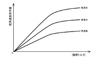
基本マップ部351は、基本マップを有し、基本マップを用いて舵角速度指令値(第1速度指令値)ωref2aを求める。基本マップは操舵トルクに対する舵角速度指令値の特性を定めたマップであり、車速に応じても変化するので、操舵トルクTt及び車速Vより舵角速度指令値ωref2aを求める。 The basic map unit 351 has a basic map, and obtains a steering angular velocity command value (first speed command value) ωref2a using the basic map. The basic map is a map that defines the characteristics of the steering angular velocity command value with respect to the steering torque, and changes according to the vehicle speed. Therefore, the steering angular velocity command value ωref2a is obtained from the steering torque Tt and the vehicle speed V.

基本マップはチューニングにより調整されており、例えば、図12に示されるように、舵角速度指令値は、操舵トルクの大きさ(絶対値)が増加するにつれて増加するが、車速が増加するにつれては減少する。高車速ほど舵角速度指令値が小さくなり、フィール(ステアリングフィール、操舵感)としては重くなり、逆に、低車速では軽いフィールとなる。アシスト制御部230で使用するアシストマップも車速が増加するにつれてアシスト制御電流指令値が減少する特性を有しているので、高速走行時に運転者により操舵介入があった場合、舵角速度指令値及びアシスト制御電流指令値の増加は抑えられ、急な操舵とならず、安全な操舵が可能である。なお、図12では操舵トルクの大きさでマップを構成しているが、正負の操舵トルクTtに応じてマップを構成しても良く、この場合、操舵トルクが正の場合と負の場合とで、変化の態様を変えても良い。 The basic map is adjusted by tuning. For example, as shown in FIG. 12, the steering angular velocity command value increases as the magnitude (absolute value) of the steering torque increases, but decreases as the vehicle speed increases. do. The higher the vehicle speed, the smaller the steering angular velocity command value, and the heavier the feel (steering feel, steering feeling), and conversely, the lighter the feel at low vehicle speeds. The assist map used by the assist control unit 230 also has a characteristic that the assist control current command value decreases as the vehicle speed increases. Therefore, when the driver intervenes in steering during high-speed driving, the steering angular velocity command value and the assist The increase in the control current command value is suppressed, and safe steering is possible without sudden steering. Although the map is configured by the magnitude of the steering torque in FIG. 12, the map may be configured according to the positive and negative steering torque Tt. In this case, the steering torque is positive and negative. , The mode of change may be changed.

ダンパゲイン部353は、舵角速度ωsに乗算されるダンパゲインGdを出力する。乗算部354にてダンパゲインGdを乗算された舵角速度ωsは、舵角速度指令値(第2速度指令値)ωref2bとして減算部355にて舵角速度指令値ωref2aから減算され、減算結果が舵角速度指令値ωref2となる。 The damper gain unit 353 outputs the damper gain Gd to be multiplied by the steering angular velocity ωs. The steering angular velocity ωs multiplied by the damper gain Gd by the multiplication unit 354 is subtracted from the steering angular velocity command value ωref2a by the subtracting unit 355 as the steering angular velocity command value (second velocity command value) ωref2b, and the subtraction result is the steering angular velocity command value. It becomes ωref2.

ダンパゲインGdは、ダンパゲイン部353が有するダンパゲインマップにより求められる。このダンパゲインマップを車速感応型とすることにより、自動操舵中での操舵介入におけるフィールに粘性感を持たせることができる。また、操舵介入後に自動操舵に戻るべくハンドルから手を離した場合の舵角の急峻な変化を緩和する機能としても使用することができる。例えば、図13に示されるように、高車速になるほど、ダンパゲインGdを大きくすることにより、粘性感を強くすることができる。 The damper gain Gd is obtained from the damper gain map of the damper gain unit 353. By making this damper gain map a vehicle speed sensitive type, it is possible to give a viscous feeling to the steering intervention during automatic steering. It can also be used as a function to alleviate a steep change in steering angle when the steering wheel is released to return to automatic steering after steering intervention. For example, as shown in FIG. 13, the higher the vehicle speed, the stronger the viscous feeling by increasing the damper gain Gd.

なお、ダンパゲイン部353及び乗算部354でダンパ演算部を構成している。また、ダンパゲインGdを乗算する舵角速度として、舵角速度演算部352から出力される舵角速度ωsではなく、舵角制御部300に入力される実舵角速度ωrを使用しても良い。この場合、舵角速度演算部352は不要となる。回転速度情報として、舵角速度ではなく、モータ速度を使用しても良い。 The damper gain unit 353 and the multiplication unit 354 form a damper calculation unit. Further, as the rudder angular velocity for multiplying the damper gain Gd, the actual rudder angular velocity ωr input to the rudder angular velocity control unit 300 may be used instead of the rudder angular velocity ωs output from the rudder angular velocity calculation unit 352. In this case, the steering angular velocity calculation unit 352 becomes unnecessary. As the rotation speed information, the motor speed may be used instead of the steering angular velocity.

舵角制御部300の加算部393では、位置制御出力可変制限部345から出力される舵角速度指令値ωref1及び操舵介入補償部350から出力される舵角速度指令値ωref2が加算され、舵角速度指令値ωrefとして出力される。 In the addition unit 393 of the steering angle control unit 300, the steering angular velocity command value ωref1 output from the position control output variable limiting unit 345 and the steering angular velocity command value ωref2 output from the steering intervention compensation unit 350 are added, and the steering angular velocity command value is added. It is output as ωref.

乗算部392では、舵角速度指令値ωrefに速度指令徐変ゲインGfa3が乗算され、舵角速度指令値ωrefgとして出力される。速度指令徐変ゲインGfa3は、手動操舵状態から自動操舵状態への切換時に円滑な切換を実現するために用いられる。なお、速度指令徐変ゲインGfa3は、舵角制御電流指令値IrefP1に乗算される舵角制御出力徐変ゲインGfa1と同期して変化する(完全な同期でなくても良い)。 In the multiplication unit 392, the speed command gradual change gain Gfa3 is multiplied by the steering angular velocity command value ωref, and the steering angular velocity command value ωrefg is output. The speed command gradual change gain Gfa3 is used to realize smooth switching when switching from the manual steering state to the automatic steering state. The speed command gradual change gain Gfa3 changes in synchronization with the steering angle control output gradual change gain Gfa1 multiplied by the rudder angle control current command value IrefP1 (it does not have to be completely synchronized).

速度指令値可変制限部360は、舵角速度指令値ωrefgに対して、制限値(上限値、下限値)を設定して制限をかけ、目標舵角速度ωtを出力する。制限値は、速度指令徐変ゲインGfa3に応じて設定される。例えば、速度指令徐変ゲインGfa3が所定の閾値未満では、制限値の大きさ(絶対値)を図14の破線で示されるような小さい値とし、それ以上では制限値の大きさを実線で示される値まで大きくする。なお、所定の閾値を切換状態での速度指令徐変ゲインGfa3の任意の値とし、Gfa3が所定の閾値未満では、制限値の大きさは破線の小さい値で固定とし、Gfa3が所定の閾値を超えたら、実線のところまで制限値の大きさを徐々に大きくするようにしても良い。なお、上限値の大きさと下限値の大きさは異なっても良い。 The speed command value variable limiting unit 360 sets a limit value (upper limit value, lower limit value) to limit the steering angular velocity command value ωrefg, and outputs a target steering angular velocity ωt. The limit value is set according to the speed command gradual change gain Gfa3. For example, when the speed command gradual change gain Gfa3 is less than a predetermined threshold value, the magnitude of the limit value (absolute value) is set to a small value as shown by the broken line in FIG. Increase to the value that can be obtained. The predetermined threshold value is set to an arbitrary value of the speed command gradual change gain Gfa3 in the switching state, and when Gfa3 is less than the predetermined threshold value, the magnitude of the limit value is fixed to a small value of the broken line, and Gfa3 sets the predetermined threshold value. If it exceeds, the size of the limit value may be gradually increased up to the solid line. The size of the upper limit value and the size of the lower limit value may be different.

舵角速度制御部370は、目標舵角速度ωt、実舵角速度ωr及び速度制御徐変ゲインGfa2を入力し、実舵角速度ωrが目標舵角速度ωtに追従するような舵角制御電流指令値IrefWを、I−P制御(比例先行型PI制御)により算出する。 The steering angular velocity control unit 370 inputs the target steering angular velocity ωt, the actual steering angular velocity ωr, and the speed control gradual change gain Gfa2, and sets the steering angular velocity command value IrefW so that the actual steering angular velocity ωr follows the target steering angular velocity ωt. Calculated by IP control (proportional leading PI control).

舵角速度制御部370の構成例を図15に示す。舵角速度制御部370は、ゲイン乗算部371及び372、積分部373、減算部374及び375並びに乗算部376を備える。 FIG. 15 shows a configuration example of the steering angular velocity control unit 370. The steering angular velocity control unit 370 includes gain multiplication units 371 and 372, an integration unit 373, subtraction units 374 and 375, and a multiplication unit 376.

ゲイン乗算部371は、減算部374で算出される目標舵角速度ωt及び実舵角速度ωrの偏差ωe(=ωt−ωr)にゲインKviを乗算し、操作量D1を出力する。積分部373は、操作量D1を積分し、制御量Ir1を算出する。乗算部376では、制御量Ir1に速度制御徐変ゲインGfa2が乗算され、制御量Ir3として出力される。速度制御徐変ゲインGfa2の乗算は、手動操舵状態と自動操舵状態間の円滑な切換を実現するために行われ、これにより、切換時の舵角速度制御での積分値の蓄積の影響を緩和することができる。ゲイン乗算部372は、実舵角速度ωrにゲインKvpを乗算し、制御量Ir2を出力する。減算部375では、制御量Ir3とIr2の偏差(Ir3−Ir2)が算出され、舵角制御電流指令値IrefWとして出力される。なお、積分部373の積分として、実装上実現可能な積分方式であれば、任意の方式を使用可能であり、擬似積分を使用する場合は、1次遅れの伝達関数及びゲインで構成すれば良い。また、速度制御徐変ゲインGfa2は、舵角制御出力徐変ゲインGfa1と同期して変化させても良い。 The gain multiplication unit 371 multiplies the deviation ωe (= ωt−ωr) of the target steering angular velocity ωt and the actual steering angular velocity ωr calculated by the subtraction unit 374 by the gain Kvi, and outputs the operation amount D1. The integrating unit 373 integrates the manipulated variable D1 and calculates the controlled variable Ir1. In the multiplication unit 376, the speed control gradual change gain Gfa2 is multiplied by the control amount Ir1 and output as the control amount Ir3. The multiplication of the speed control gradual change gain Gfa2 is performed in order to realize smooth switching between the manual steering state and the automatic steering state, thereby alleviating the influence of the accumulation of the integrated value in the steering angular velocity control at the time of switching. be able to. The gain multiplication unit 372 multiplies the actual steering angular velocity ωr by the gain Kvp and outputs the controlled variable Ir2. In the subtraction unit 375, the deviation (Ir3-Ir2) between the control quantities Ir3 and Ir2 is calculated and output as the steering angle control current command value IrefW. As the integration of the integration unit 373, any method can be used as long as it is an integration method feasible in terms of implementation, and when pseudo-integral is used, it may be composed of a transfer function with a first-order lag and a gain. .. Further, the speed control gradual change gain Gfa2 may be changed in synchronization with the steering angle control output gradual change gain Gfa1.

なお、舵角速度制御部370はI−P制御を使用しているが、目標舵角速度に対して実舵角速度を追従させられるならば、一般的に使用されている制御方法を使用しても良い。例えばPI制御、2自由度PI制御、モデル規範制御、モデルマッチング制御、ロバスト制御、更に、外乱を推定し、外乱成分を打ち消す補償手段を一部に組み合わせた制御方法等を使用しても良い。 Although the steering angular velocity control unit 370 uses the IP control, a generally used control method may be used as long as the actual steering angular velocity can be made to follow the target steering angular velocity. .. For example, PI control, 2-degree-of-freedom PI control, model norm control, model matching control, robust control, and a control method in which a compensating means for estimating a disturbance and canceling the disturbance component is partially combined may be used.

ハンドル制振部380は、トーションバートルク信号である操舵トルクTtに基づいて、ハンドルの振動を制振する。自動操舵中のハンドル振動に対して、ハンドル振動除去部330も効果を奏するが、ハンドル制振部380により、更に効果を向上させることができる。ハンドル制振部380は、ゲインと位相補償によりハンドル振動の制振を行い、トーションバーの捩れを解消する方向に働く舵角制御電流指令値IrefVを出力する。また、ハンドル制振部380は、捩れ角を低減する方向に働き、運転者による手入力の介入時の引っ掛かりの違和感を低減する効果も兼ねている。 The steering wheel vibration damping unit 380 damps the vibration of the steering wheel based on the steering torque Tt, which is a torsion bar torque signal. The steering wheel vibration removing unit 330 also has an effect on the steering wheel vibration during automatic steering, but the effect can be further improved by the steering wheel vibration damping unit 380. The handle vibration damping unit 380 suppresses the vibration of the handle by gain and phase compensation, and outputs a steering angle control current command value IrefV that works in the direction of eliminating the twist of the torsion bar. Further, the handle vibration damping unit 380 works in the direction of reducing the twist angle, and also has an effect of reducing the discomfort of being caught when the driver manually inputs.

ハンドル制振部380の構成例を図16に示す。ハンドル制振部380は、ゲイン部381及び制振位相補償部382を備える。ゲイン部381は、操舵トルクTtにゲインKvを乗算し、制御量Irvを出力する。制振位相補償部382は、例えば1次フィルタで構成され、制御量Irvを舵角制御電流指令値IrefVに変換する。1次フィルタではなく、2次以上の位相補償フィルタで構成しても良い。 FIG. 16 shows a configuration example of the handle vibration damping unit 380. The handle vibration damping unit 380 includes a gain unit 381 and a vibration damping phase compensation unit 382. The gain unit 381 multiplies the steering torque Tt by the gain Kv and outputs the controlled variable Irv. The vibration damping phase compensation unit 382 is composed of, for example, a primary filter, and converts the controlled variable Irv into the steering angle control current command value IrefV. It may be composed of a second-order or higher-order phase compensation filter instead of the first-order filter.

加算部394では、舵角速度制御部370から出力される舵角制御電流指令値IrefW及びハンドル制振部380から出力される舵角制御電流指令値IrefVが加算され、舵角制御電流指令値IrefP2として出力される。 In the addition unit 394, the steering angle control current command value IrefW output from the steering angular velocity control unit 370 and the steering angle control current command value IrefV output from the steering wheel vibration damping unit 380 are added to obtain the steering angle control current command value IrefP2. It is output.

舵角制御電流指令値制限部390は、舵角制御電流指令値IrefP2に対して、過出力防止のために、制限値(上限値、下限値)を設定して制限をかけ、舵角制御電流指令値IrefP1を出力する。例えば、図17に示されるように、上限値及び下限値を設定して舵角制御電流指令値IrefP2に対して制限をかける。なお、上限値の大きさ(絶対値)と下限値の大きさは異なっても良い。 The steering angle control current command value limiting unit 390 sets a limiting value (upper limit value, lower limit value) to limit the steering angle control current command value IrefP2 in order to prevent overoutput, and limits the steering angle control current. The command value IrefP1 is output. For example, as shown in FIG. 17, an upper limit value and a lower limit value are set to limit the steering angle control current command value IrefP2. The magnitude of the upper limit value (absolute value) and the magnitude of the lower limit value may be different.

切換部240は、乗算部241及び242並びに加算部243で構成されている。 The switching unit 240 includes multiplication units 241 and 242 and addition units 243.

切換部240の乗算部241では、舵角制御部300から出力される舵角制御電流指令値IrefP1に、切換判定/徐変ゲイン生成部220から出力される舵角制御出力徐変ゲインGfa1が乗算され、舵角制御電流指令値IrefPとして出力される。舵角制御出力徐変ゲインGfa1は、手動操舵状態と自動操舵状態間の切換動作を円滑に行い、運転者への違和感や安全性等を実現するために用いられる。乗算部242では、アシスト制御部230から出力されるアシスト制御電流指令値IrefT1にアシスト制御出力徐変ゲインGft1が乗算され、アシスト制御電流指令値IrefTとして出力される。アシスト制御出力徐変ゲインGft1は、手動操舵状態と自動操舵状態間の切換動作を円滑に行い、自動運転中の運転者による操舵介入を実現するために用いられる。加算部243では、舵角制御電流指令値IrefP及びアシスト制御電流指令値IrefTが加算され、電流指令値Irefとして出力される。 In the multiplication unit 241 of the switching unit 240, the steering angle control output gradual change gain Gfa1 output from the switching determination / gradual change gain generation unit 220 is multiplied by the steering angle control current command value IrefP1 output from the steering angle control unit 300. It is output as a rudder angle control current command value IrefP. The steering angle control output gradual change gain Gfa1 is used to smoothly switch between the manual steering state and the automatic steering state, and to realize a sense of discomfort to the driver, safety, and the like. In the multiplication unit 242, the assist control output gradual change gain Gft1 is multiplied by the assist control current command value IrefT1 output from the assist control unit 230, and the assist control current command value IrefT is output. The assist control output gradual change gain Gft1 is used to smoothly switch between the manual steering state and the automatic steering state and to realize steering intervention by the driver during automatic driving. In the addition unit 243, the steering angle control current command value IrefP and the assist control current command value IrefT are added and output as the current command value Iref.

前述のアシスト制御部230で使用されるアシストマップ徐変ゲインGft2も、アシスト制御出力徐変ゲインGft1と同じ目的で用いられる。自動操舵状態において、図6(B)及び(C)に示されるように、Gft1をαt1に、Gft2をαt2に設定し、αt1及びαt2を調整することにより、システムの安定性を向上させ、振動の発生を抑えることが可能となる。また、自動操舵状態におけるシステムの安定性を維持できるのであれば、簡易的にαt1を0%、αt2を100%としても良い。この場合、αt1は0%ということより、アシスト制御電流指令値IrefTはゼロ指令となり、アシスト制御をなくした状態においても操舵介入を実現できることとなる。 The assist map gradual change gain Gft2 used in the above-mentioned assist control unit 230 is also used for the same purpose as the assist control output gradual change gain Gft1. In the automatic steering state, as shown in FIGS. 6B and 6C, Gft1 is set to αt1, Gft2 is set to αt2, and αt1 and αt2 are adjusted to improve the stability of the system and vibrate. Can be suppressed. Further, if the stability of the system in the automatic steering state can be maintained, αt1 may be simply set to 0% and αt2 may be set to 100%. In this case, since αt1 is 0%, the assist control current command value IrefT becomes a zero command, and steering intervention can be realized even when the assist control is eliminated.

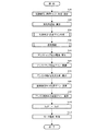
このような構成において、EPS側ECU200の動作例を、図18〜図23のフローチャートを参照して説明する。 In such a configuration, an operation example of the EPS side ECU 200 will be described with reference to the flowcharts of FIGS. 18 to 23.

動作を開始すると、EPS状態量検出部210は実操舵角θr、操舵トルクTt、車速Vを検出し(ステップS10)、実操舵角θrを切換判定/徐変ゲイン生成部220及び舵角制御部300に、操舵トルクTtを切換判定/徐変ゲイン生成部220、舵角制御部300及びアシスト制御部230に、車速Vを舵角制御部300及びアシスト制御部230にそれぞれ出力する。更に、EPS状態量検出部210は、実操舵角θrより実舵角速度ωrを算出し(ステップS20)、舵角制御部300に出力する。 When the operation is started, the EPS state amount detection unit 210 detects the actual steering angle θr, the steering torque Tt, and the vehicle speed V (step S10), and switches the actual steering angle θr. The steering torque Tt is output to the steering angle control unit 220, the steering angle control unit 300, and the assist control unit 230, and the vehicle speed V is output to the steering angle control unit 300 and the assist control unit 230, respectively. Further, the EPS state quantity detection unit 210 calculates the actual steering angular velocity ωr from the actual steering angle θr (step S20) and outputs it to the steering angle control unit 300.

操舵トルクTt及び実操舵角θrを入力した切換判定/徐変ゲイン生成部220には、舵角制御部300から出力された1サンプル前の目標操舵角θtが入力されている。切換判定/徐変ゲイン生成部220は、それらを用いて、車両側ECU100から出力される切換信号SWの入力も踏まえて自動操舵と手動操舵の切換判定を行い、その判定結果に基づいて徐変ゲインを決定し(ステップS30)、徐変ゲインGfa2、Gfa3及びGfa4を舵角制御部300に、Gft2をアシスト制御部230に、Gfa1及びGft1を切換部240にそれぞれ出力する。また、操舵状態判定信号Jsを舵角制御部300に出力する。切換判定/徐変ゲイン生成部220の動作の詳細については後述する。 The target steering angle θt one sample before output from the steering angle control unit 300 is input to the switching determination / gradual gain generation unit 220 in which the steering torque Tt and the actual steering angle θr are input. The switching determination / gradual change gain generation unit 220 uses them to perform a switching determination between automatic steering and manual steering based on the input of the switching signal SW output from the vehicle side ECU 100, and the gradual change based on the determination result. The gain is determined (step S30), and the gradual change gains Gfa2, Gfa3 and Gfa4 are output to the steering angle control unit 300, Gft2 is output to the assist control unit 230, and Gfa1 and Gft1 are output to the switching unit 240, respectively. Further, the steering state determination signal Js is output to the steering angle control unit 300. The details of the operation of the switching determination / gradual gain generation unit 220 will be described later.

舵角制御部300は、車両側ECU100からの舵角指令値θref、EPS状態量検出部210からの実操舵角θr、実舵角速度ωr、操舵トルクTt及び車速V、並びに切換判定/徐変ゲイン生成部220からの徐変ゲインGfa2、Gfa3、Gfa4及び操舵状態判定信号Jsを入力し、それらを用いて舵角制御電流指令値IrefP1を算出し(ステップS40)、切換部240に出力する。舵角制御部300の動作の詳細については後述する。 The steering angle control unit 300 includes a steering angle command value θref from the vehicle-side ECU 100, an actual steering angle θr from the EPS state amount detection unit 210, an actual steering angle speed ωr, a steering torque Tt and a vehicle speed V, and a switching determination / gradual change gain. The gradual change gains Gfa2, Gfa3, Gfa4 and the steering state determination signal Js are input from the generation unit 220, the steering angle control current command value IrefP1 is calculated using them (step S40), and is output to the switching unit 240. The details of the operation of the steering angle control unit 300 will be described later.

アシスト制御部230は、操舵トルクTt、車速V及びアシストマップ徐変ゲインGft2を入力し、図2に示される電流指令値演算部31と同様の動作により、アシストマップ出力電流(電流値)を算出する(ステップS50)。そして、アシストマップ出力電流にアシストマップ徐変ゲインGft2を乗算し(ステップS60)、乗算結果に対して、図2に示される加算部32A、電流制限部33及び補償信号生成部34と同様の動作を行い、アシスト制御電流指令値IrefT1を算出し(ステップS70)、切換部240に出力する。 The assist control unit 230 inputs the steering torque Tt, the vehicle speed V, and the assist map gradual change gain Gft2, and calculates the assist map output current (current value) by the same operation as the current command value calculation unit 31 shown in FIG. (Step S50). Then, the assist map output current is multiplied by the assist map gradual change gain Gft2 (step S60), and the multiplication result is operated in the same manner as the addition unit 32A, the current limiting unit 33, and the compensation signal generation unit 34 shown in FIG. Is performed, the assist control current command value IrefT1 is calculated (step S70), and is output to the switching unit 240.

切換部240は、入力した舵角制御電流指令値IrefP1に対して舵角制御出力徐変ゲインGfa1を乗算部241で乗算し(ステップS80)、乗算結果である舵角制御電流指令値IrefPを加算部243に出力する。また、入力したアシスト制御電流指令値IrefT1に対してアシスト制御出力徐変ゲインGft1を乗算部242で乗算し(ステップS90)、乗算結果であるアシスト制御電流指令値IrefTを加算部243に出力する。加算部243は、舵角制御電流指令値IrefP及びアシスト制御電流指令値IrefTを加算し(ステップS100)、加算結果である電流指令値Irefを電流制御/駆動部250に出力する。 The switching unit 240 multiplies the input steering angle control current command value IrefP1 by the steering angle control output gradual change gain Gfa1 by the multiplication unit 241 (step S80), and adds the steering angle control current command value IrefP which is the multiplication result. Output to unit 243. Further, the assist control output gradual change gain Gft1 is multiplied by the multiplication unit 242 with the input assist control current command value IrefT1 (step S90), and the assist control current command value IrefT which is the multiplication result is output to the addition unit 243. The addition unit 243 adds the steering angle control current command value IrefP and the assist control current command value IrefT (step S100), and outputs the current command value Iref, which is the addition result, to the current control / drive unit 250.

電流制御/駆動部250は、図2に示される減算部32B、PI制御部35、PWM制御部36及びインバータ37と同様の動作により、電流指令値Iref及びモータ電流検出器38で検出されたモータ電流Imを用いて、モータ電流Imが電流指令値Irefに追従するように制御し(ステップS110)、モータを駆動制御する。 The current control / drive unit 250 operates in the same manner as the subtraction unit 32B, the PI control unit 35, the PWM control unit 36, and the inverter 37 shown in FIG. 2, and the motor detected by the current command value Iref and the motor current detector 38. Using the current Im, the motor current Im is controlled to follow the current command value Iref (step S110), and the motor is driven and controlled.

切換判定/徐変ゲイン生成部220の動作例の詳細を、図19及び図20のフローチャートを参照して説明する。なお、操舵状態判定部224において、直前操舵状態には「手動操舵」が、保持する切換信号SWには「アシスト制御モード」が、操舵状態判定信号Jsには「手動操舵」がそれぞれ初期値として設定されているとする。 The details of the operation example of the switching determination / gradual change gain generation unit 220 will be described with reference to the flowcharts of FIGS. 19 and 20. In the steering state determination unit 224, "manual steering" is used as the initial value for the immediately preceding steering state, "assist control mode" is used for the switching signal SW to be held, and "manual steering" is used as the initial value for the steering state determination signal Js. Suppose it is set.

入力した操舵トルクTt、目標操舵角θt及び実操舵角θrは、切換判定部221内の手入力判定部223に入力される。手入力判定部223では、操舵トルクTtが判定部223Aに、目標操舵角θtが舵角制御モデル部228に、実操舵角θrが減算部229に入力される。 The input steering torque Tt, target steering angle θt, and actual steering angle θr are input to the manual input determination unit 223 in the switching determination unit 221. In the manual input determination unit 223, the steering torque Tt is input to the determination unit 223A, the target steering angle θt is input to the steering angle control model unit 228, and the actual steering angle θr is input to the subtraction unit 229.

舵角制御モデル部228は、目標操舵角θtから推定操舵角θiを演算する(ステップS210)。推定操舵角θiは減算部229に加算入力され、実操舵角θrを減算され(ステップS220)、誤差dθ(=θi−θr)が判定部223Bに入力される。 The steering angle control model unit 228 calculates the estimated steering angle θi from the target steering angle θt (step S210). The estimated steering angle θi is additionally input to the subtraction unit 229, the actual steering angle θr is subtracted (step S220), and the error dθ (= θi−θr) is input to the determination unit 223B.

判定部223Aは、操舵トルクTtを平滑化フィルタ部225A及び225Bで平滑化し、平滑後の操舵トルクTta及びTtbの絶対値|Tta|及び|Ttb|を絶対値化部226A及び226Bで求める(ステップS230)。絶対値|Tta|及び|Ttb|は判定処理部227Aに入力される。判定処理部227Aは、絶対値|Ttb|が閾値TthB以上の場合(ステップS240)、「手入力あり3」と判定する(ステップS250)。絶対値|Ttb|が閾値TthB未満の場合(ステップS240)、絶対値|Tta|が閾値TthA3以上ならば(ステップS260)、「手入力あり3」と判定し(ステップS250)、絶対値|Tta|が閾値TthA3未満で閾値TthA2以上ならば(ステップS270)、「手入力あり2」と判定し(ステップS280)、絶対値|Tta|が閾値TthA2未満で閾値TthA1以上ならば(ステップS290)、「手入力あり1」と判定し(ステップS300)、絶対値|Tta|が閾値TthA1未満ならば(ステップS290)、「手入力なし」と判定する(ステップS310)。判定結果は手入力判定信号Jh1として操舵状態判定部224に出力される。 The determination unit 223A smoothes the steering torque Tt with the smoothing filter units 225A and 225B, and obtains the absolute values | Tta | and | Ttb | of the smoothed steering torques Tta and Ttb with the absolute value conversion units 226A and 226B (step). S230). Absolute values | Tta | and | Ttb | are input to the determination processing unit 227A. When the absolute value | Ttb | is equal to or greater than the threshold value TthB (step S240), the determination processing unit 227A determines that "with manual input 3" (step S250). If the absolute value | Ttb | is less than the threshold value TthB (step S240), and if the absolute value | Tta | is greater than or equal to the threshold value TthA3 (step S260), it is determined as "manual input 3" (step S250), and the absolute value | Tta | If | is less than the threshold TthA3 and is the threshold TthA2 or more (step S270), it is determined that “with manual input 2” (step S280), and if the absolute value | Tta | is less than the threshold TthA2 and is the threshold TthA1 or more (step S290). If it is determined that "with manual input 1" (step S300) and the absolute value | Tta | is less than the threshold value TthA1 (step S290), it is determined that "without manual input" (step S310). The determination result is output to the steering state determination unit 224 as a manual input determination signal Jh1.

判定部223Bは、誤差dθを平滑化フィルタ部225C及び225Dで平滑化し、平滑後の誤差dθa及びdθbの絶対値|dθa|及び|dθb|を絶対値化部226C及び226Dで求める(ステップS320)。絶対値|dθa|及び|dθb|は判定処理部227Bに入力される。判定処理部227Bは、絶対値|dθb|が閾値θthB以上の場合(ステップS330)、「手入力あり3」と判定する(ステップS340)。絶対値|dθb|が閾値θthB未満の場合(ステップS330)、絶対値|dθa|が閾値θthA3以上ならば(ステップS350)、「手入力あり3」と判定し(ステップS340)、絶対値|dθa|が閾値θthA3未満で閾値θthA2以上ならば(ステップS360)、「手入力あり2」と判定し(ステップS370)、絶対値|dθa|が閾値θthA2未満で閾値θthA1以上ならば(ステップS380)、「手入力あり1」と判定し(ステップS390)、絶対値|dθa|が閾値θthA1未満ならば(ステップS380)、「手入力なし」と判定する(ステップS400)。判定結果は手入力判定信号Jh2として操舵状態判定部224に出力される。なお、判定部223Aの動作と判定部223Bの動作は、順番が逆でも、並行して実行されても良い。 The determination unit 223B smoothes the error dθ by the smoothing filter units 225C and 225D, and obtains the absolute values | dθa | and | dθb | of the smoothed errors dθa and dθb by the absolute valueization units 226C and 226D (step S320). .. Absolute values | dθa | and | dθb | are input to the determination processing unit 227B. When the absolute value | dθb | is equal to or greater than the threshold value θthB (step S330), the determination processing unit 227B determines that “with manual input 3” (step S340). If the absolute value | dθb | is less than the threshold value θthB (step S330), and if the absolute value | dθa | is greater than or equal to the threshold value θthA3 (step S350), it is determined that “with manual input 3” (step S340), and the absolute value | dθa | If | is less than the threshold value θthA3 and is greater than or equal to the threshold value θthA2 (step S360), it is determined that “with manual input 2” (step S370), and if the absolute value | dθa | is less than the threshold value θthA2 and is greater than or equal to the threshold value θthA1 (step S380). If it is determined that "with manual input 1" (step S390) and the absolute value | dθa | is less than the threshold value θthA1 (step S380), it is determined that "without manual input" (step S400). The determination result is output to the steering state determination unit 224 as a manual input determination signal Jh2. The operation of the determination unit 223A and the operation of the determination unit 223B may be executed in the reverse order or in parallel.

操舵状態判定部224は、切換信号SWの入力の有無を確認し(ステップS410)、切換信号SWを入力していたら、保持している切換信号SWの値を更新する(ステップS420)。そして、入力した手入力判定信号Jh1及びJh2をそれぞれ判定信号α及びβとし、直前操舵状態、切換信号SWを用いて、表1〜表3の条件判定に従って操舵状態の判定を行う(ステップS430)。判定結果は、徐変ゲイン生成部222及び舵角制御部300に操舵状態判定信号Jsとして出力されると共に、次回の判定における直前操舵状態として保持される(ステップS440)。 The steering state determination unit 224 confirms whether or not the switching signal SW is input (step S410), and if the switching signal SW is input, updates the value of the holding switching signal SW (step S420). Then, the input manual input determination signals Jh1 and Jh2 are set as determination signals α and β, respectively, and the steering state is determined according to the condition determinations in Tables 1 to 3 using the immediately preceding steering state and the switching signal SW (step S430). .. The determination result is output as a steering state determination signal Js to the gradual gain generation unit 222 and the steering angle control unit 300, and is held as the immediately preceding steering state in the next determination (step S440).

徐変ゲイン生成部222は、操舵状態判定信号Jsの値を確認する(ステップS450)。操舵状態判定信号Jsが「手動操舵」の場合、各徐変ゲイン(Gfa1〜Gfa4、Gft1、Gft2)を手動操舵状態での値(Gfa1〜Gfa4では0%、Gft1及びGft2では100%)に遷移させる(ステップS460)。操舵状態判定信号Jsが「自動操舵1」の場合、各徐変ゲインを自動操舵状態での値(Gfa1〜Gfa4では100%、Gft1ではαt1、Gft2ではαt2)に遷移させる(ステップS470)。操舵状態判定信号Jsが「自動操舵2」の場合は、各徐変ゲインはそのままとする。 The gradual gain generation unit 222 confirms the value of the steering state determination signal Js (step S450). When the steering state determination signal Js is "manual steering", each gradual change gain (Gfa1 to Gfa4, Gft1, Gft2) is changed to the value in the manual steering state (0% for Gfa1 to Gfa4, 100% for Gft1 and Gft2). (Step S460). When the steering state determination signal Js is "automatic steering 1", each gradual change gain is changed to the value in the automatic steering state (100% in Gfa1 to Gfa4, αt1 in Gft1, αt2 in Gft2) (step S470). When the steering state determination signal Js is "automatic steering 2", each gradual change gain is left as it is.

舵角制御部300の動作例の詳細を、図21〜23のフローチャートを参照して説明する。 Details of an operation example of the steering angle control unit 300 will be described with reference to the flowcharts of FIGS. 21 to 23.

舵角指令値可変制限部310は、入力した舵角指令徐変ゲインGfa4の値を確認し(ステップS610)、Gfa4が0%の場合、制限値を、図8に示される「手動操舵時」の制限値とし(ステップS620)、Gfa4が100%の場合、図8に示される「自動操舵時」の制限値とし(ステップS630)、Gfa4が0〜100%の場合、中間の値を制限値とする(ステップS640)。そして、設定された制限値を用いて、車両側ECU100から入力した舵角指令値θrefに対して制限をかけ(ステップS650)、舵角指令値θref1を出力する。 The steering angle command value variable limiting unit 310 confirms the input steering angle command gradual change gain Gfa4 value (step S610), and when Gfa4 is 0%, the steering angle command value variable limiting unit 310 sets the limiting value to “during manual steering” shown in FIG. (Step S620), when Gfa4 is 100%, the limit value for "automatic steering" shown in FIG. 8 (step S630), and when Gfa4 is 0 to 100%, the intermediate value is the limit value. (Step S640). Then, using the set limit value, a limit is applied to the steering angle command value θref input from the vehicle side ECU 100 (step S650), and the steering angle command value θref1 is output.

舵角指令値θref1は、操舵状態判定信号Js及び実操舵角θrと共に、可変レート制限部320に入力される。可変レート制限部320は、操舵状態判定信号Jsの値を確認し(ステップS660)、操舵状態判定信号Jsが「手動操舵」又は「自動操舵2」の場合、制限値をゼロとし(ステップS670、S681)、「手動操舵」の場合は、更に、保持している1サンプル前の舵角指令値θref1の値を実操舵角θrの値にする(ステップS671)。ステップS671は、舵角制御が開始された時点では、前の舵角制御終了時の値が残った状態であり、その値をそのまま使用すると舵角指令値の急変によりハンドルが急変するおそれがあるので、実操舵角θrと一致させた状態で開始させることにより急変を抑制するための処置である。操舵状態判定信号Jsが「自動操舵1」の場合、制限値を予め定められた値とする(ステップS680)。そして、舵角指令値θref1と1サンプル前の舵角指令値θref1との差分(変化量)を算出する(ステップS690)。変化量の絶対値が制限値より大きい場合(ステップS700)、変化量の絶対値が制限値となるように、舵角指令値θref1を加減算し(ステップS710)、舵角指令値θref2として出力する(ステップS720)。変化量の絶対値が制限値以下の場合(ステップS700)、舵角指令値θref1をそのまま舵角指令値θref2として出力する(ステップS720)。 The steering angle command value θref1 is input to the variable rate limiting unit 320 together with the steering state determination signal Js and the actual steering angle θr. The variable rate limiting unit 320 confirms the value of the steering state determination signal Js (step S660), and when the steering state determination signal Js is "manual steering" or "automatic steering 2", the limit value is set to zero (step S670, In the case of S681) and "manual steering", the value of the rudder angle command value θref1 one sample before being held is further set to the value of the actual steering angle θr (step S671). In step S671, when the steering angle control is started, the value at the end of the previous steering angle control remains, and if the value is used as it is, the steering wheel may suddenly change due to a sudden change in the steering angle command value. Therefore, this is a measure for suppressing sudden changes by starting in a state where the actual steering angle θr is matched. When the steering state determination signal Js is "automatic steering 1", the limit value is set to a predetermined value (step S680). Then, the difference (change amount) between the steering angle command value θref1 and the steering angle command value θref1 one sample before is calculated (step S690). When the absolute value of the amount of change is larger than the limit value (step S700), the steering angle command value θref1 is added or subtracted (step S710) so that the absolute value of the amount of change becomes the limit value, and the rudder angle command value θref2 is output. (Step S720). When the absolute value of the amount of change is equal to or less than the limit value (step S700), the steering angle command value θref1 is output as it is as the steering angle command value θref2 (step S720).

舵角指令値θref2は、乗算部391で舵角指令徐変ゲインGfa4を乗算され(ステップS730)、舵角指令値θref3として出力され、舵角指令値θref3はハンドル振動除去部330に入力される。 The steering angle command value θref2 is multiplied by the steering angle command gradual change gain Gfa4 by the multiplication unit 391 (step S730), output as the steering angle command value θref3, and the steering angle command value θref3 is input to the steering wheel vibration removing unit 330. ..

ハンドル振動除去部330は、舵角指令値θref3に対して、振動周波数成分を低減し(ステップS740)、目標操舵角θtとして位置制御部340及び切換判定/徐変ゲイン生成部220に出力する。 The handle vibration removing unit 330 reduces the vibration frequency component with respect to the steering angle command value θref3 (step S740), and outputs the target steering angle θt to the position control unit 340 and the switching determination / gradual gain generation unit 220.

目標操舵角θtは、位置制御部340内の減算部342に加算入力される。減算部342には実操舵角θrが減算入力されており、減算部342にて目標操舵角θtと実操舵角θrの偏差θeが求められる(ステップS750)。偏差θeは比例ゲイン部341に入力され、比例ゲイン部341は、偏差θeに比例ゲインKppを乗算し、舵角速度指令値ωref0を算出する(ステップS760)。舵角速度指令値ωref0は位置制御出力可変制限部345に入力される。 The target steering angle θt is additionally input to the subtraction unit 342 in the position control unit 340. The actual steering angle θr is subtracted and input to the subtraction unit 342, and the subtraction unit 342 obtains the deviation θe between the target steering angle θt and the actual steering angle θr (step S750). The deviation θe is input to the proportional gain unit 341, and the proportional gain unit 341 multiplies the deviation θe by the proportional gain Kpp to calculate the steering angle speed command value ωref0 (step S760). The steering angular velocity command value ωref0 is input to the position control output variable limiting unit 345.

位置制御出力可変制限部345は、舵角速度指令値ωref0と共に、操舵状態判定信号Jsを入力し、操舵状態判定信号Jsの値を確認する(ステップS770)。操舵状態判定信号Jsが「手動操舵」又は「自動操舵2」の場合、制限値を設定値Bとし(ステップS780、S800)、「自動操舵1」の場合、制限値を設定値Aとする(ステップS790)。そして、設定された制限値を用いて、舵角速度指令値ωref0に対して制限をかけ(ステップS810)、舵角速度指令値ωref1を出力する。舵角速度指令値ωref1は加算部393に入力される。 The position control output variable limiting unit 345 inputs the steering state determination signal Js together with the steering angular velocity command value ωref0, and confirms the value of the steering state determination signal Js (step S770). When the steering state determination signal Js is "manual steering" or "automatic steering 2", the limit value is set to the set value B (steps S780 and S800), and when "automatic steering 1", the limit value is set to the set value A (step S780, S800). Step S790). Then, using the set limit value, a limit is applied to the steering angular velocity command value ωref0 (step S810), and the steering angular velocity command value ωref1 is output. The steering angular velocity command value ωref1 is input to the addition unit 393.

一方、操舵介入補償部350は、車速V、操舵トルクTt及び実操舵角θrを入力し、舵角速度指令値ωref2を算出する(ステップS820)。操舵介入補償部350の動作例については、図23を参照して説明する。 On the other hand, the steering intervention compensation unit 350 inputs the vehicle speed V, the steering torque Tt, and the actual steering angle θr, and calculates the steering angular velocity command value ωref2 (step S820). An operation example of the steering intervention compensation unit 350 will be described with reference to FIG.

操舵介入補償部350に入力された車速Vは基本マップ部351及びダンパゲイン部353に、操舵トルクTtは基本マップ部351に、実操舵角θrは舵角速度演算部352に入力される。 The vehicle speed V input to the steering intervention compensation unit 350 is input to the basic map unit 351 and the damper gain unit 353, the steering torque Tt is input to the basic map unit 351, and the actual steering angle θr is input to the steering angular velocity calculation unit 352.

基本マップ部351は、図12に示される基本マップを用いて、操舵トルクTt及び車速Vに基づいて舵角速度指令値ωref2aを求める(ステップS821)。舵角速度指令値ωref2aは減算部355に加算入力される。 The basic map unit 351 obtains the steering angular velocity command value ωref2a based on the steering torque Tt and the vehicle speed V using the basic map shown in FIG. 12 (step S821). The steering angular velocity command value ωref2a is additionally input to the subtraction unit 355.

舵角速度演算部352は、実操舵角θrを微分部352Aで微分し(ステップS822)、更にLPF352Bでローパスフィルタ処理を実行し、舵角速度ωsとして乗算部354に出力する。 The steering angular velocity calculation unit 352 differentiates the actual steering angle θr with the differential unit 352A (step S822), further executes low-pass filter processing with the LPF352B, and outputs the steering angular velocity ωs to the multiplication unit 354.

ダンパゲイン部353は、図13に示されるダンパゲインマップを用いて、車速Vに基づいてダンパゲインGdを求め(ステップS823)、ダンパゲインGdは乗算部354に入力され、舵角速度ωsに乗算され(ステップS824)、乗算結果は舵角速度指令値ωref2bとして減算部355に減算入力される。 The damper gain unit 353 obtains the damper gain Gd based on the vehicle speed V using the damper gain map shown in FIG. 13 (step S823), and the damper gain Gd is input to the multiplication unit 354 and multiplied by the steering angular velocity ωs (step S824). ), The multiplication result is subtracted and input to the subtraction unit 355 as the steering angular velocity command value ωref2b.

減算部355では舵角速度指令値ωref2aから舵角速度指令値ωref2bが減算され(ステップS825)、舵角速度指令値ωref2が出力される(ステップS826)。 In the subtraction unit 355, the steering angular velocity command value ωref2b is subtracted from the steering angular velocity command value ωref2a (step S825), and the steering angular velocity command value ωref2 is output (step S826).

操舵介入補償部350から出力された舵角速度指令値ωref2は加算部393に入力される。 The steering angular velocity command value ωref2 output from the steering intervention compensation unit 350 is input to the addition unit 393.

加算部393に入力された舵角速度指令値ωref1及びωref2は加算され(ステップS840)、舵角速度指令値ωrefとして出力される。舵角速度指令値ωrefは、乗算部392で速度指令徐変ゲインGfa3を乗算され(ステップS850)、舵角速度指令値ωrefgとして速度指令値可変制限部360に入力される。 The steering angular velocity command values ωref1 and ωref2 input to the addition unit 393 are added (step S840) and output as the steering angular velocity command value ωref. The steering angular velocity command value ωref is multiplied by the speed command gradual change gain Gfa3 by the multiplication unit 392 (step S850), and is input to the speed command value variable limiting unit 360 as the steering angular velocity command value ωrefg.

速度指令値可変制限部360は、舵角速度指令値ωrefgと共に、速度指令徐変ゲインGfa3を入力し、速度指令徐変ゲインGfa3の値を確認する(ステップS860)。そして、Gfa3が所定の閾値未満の場合、制限値を、図14に示される「Gfa3小」の制限値とし(ステップS870)、所定の閾値以上の場合、「Gfa3大」の制限値とする(ステップS880)。設定された制限値を用いて、舵角速度指令値ωrefgに対して制限をかけ(ステップS890)、目標舵角速度ωtを出力する。目標舵角速度ωtは舵角速度制御部370に入力される。 The speed command value variable limiting unit 360 inputs the speed command gradual change gain Gfa3 together with the steering angular velocity command value ωrefg, and confirms the value of the speed command gradual change gain Gfa3 (step S860). Then, when Gfa3 is less than a predetermined threshold value, the limit value is set to the limit value of "Gfa3 small" shown in FIG. 14 (step S870), and when it is equal to or more than the predetermined threshold value, the limit value is set to "Gfa3 large" (step S870). Step S880). Using the set limit value, a limit is applied to the steering angular velocity command value ωrefg (step S890), and the target steering angular velocity ωt is output. The target steering angular velocity ωt is input to the steering angular velocity control unit 370.

舵角速度制御部370は、目標舵角速度ωtと共に、実舵角速度ωr及び速度制御徐変ゲインGfa2を入力する。目標舵角速度ωtは減算部374に加算入力され、実舵角速度ωrは減算部374に減算入力され、目標舵角速度ωtと実舵角速度ωrの偏差ωeがゲイン乗算部371に入力される(ステップS900)。ゲイン乗算部371は偏差ωeにゲインKviを乗算し(ステップS910)、操作量D1を出力する。操作量D1は積分部373に入力され、積分部373は、操作量D1を積分して制御量Ir1を算出し(ステップS920)、乗算部376に出力する。乗算部376は、制御量Ir1に速度制御徐変ゲインGfa2を乗算し(ステップS930)、制御量Ir3を出力する。制御量Ir3は減算部375に加算入力される。また、実舵角速度ωrはゲイン乗算部372にも入力され、ゲイン乗算部372は、実舵角速度ωrにゲインKvpを乗算し(ステップS940)、制御量Ir2を出力し、制御量Ir2は減算部375に減算入力される。減算部375では、制御量Ir3とIr2の偏差が算出され(ステップS950)、舵角制御電流指令値IrefWとして、加算部394に出力される。 The steering angular velocity control unit 370 inputs the actual steering angular velocity ωr and the speed control gradual change gain Gfa2 together with the target steering angular velocity ωt. The target steering angular velocity ωt is additionally input to the subtracting unit 374, the actual steering angular velocity ωr is subtracted and input to the subtracting unit 374, and the deviation ωe between the target steering angular velocity ωt and the actual steering angular velocity ωr is input to the gain multiplication unit 371 (step S900). ). The gain multiplication unit 371 multiplies the deviation ωe by the gain Kvi (step S910) and outputs the manipulated variable D1. The operation amount D1 is input to the integration unit 373, and the integration unit 373 integrates the operation amount D1 to calculate the control amount Ir1 (step S920) and outputs the control amount D1 to the multiplication unit 376. The multiplication unit 376 multiplies the control amount Ir1 by the speed control gradual change gain Gfa2 (step S930), and outputs the control amount Ir3. The control amount Ir3 is additionally input to the subtraction unit 375. Further, the actual steering angular velocity ωr is also input to the gain multiplication unit 372, the gain multiplication unit 372 multiplies the actual steering angular velocity ωr by the gain Kvp (step S940), outputs the control amount Ir2, and the control amount Ir2 is the subtraction unit. It is subtracted and input to 375. The subtraction unit 375 calculates the deviation between the control quantities Ir3 and Ir2 (step S950), and outputs the steering angle control current command value IrefW to the addition unit 394.

操舵トルクTtはハンドル制振部380にも入力される。ハンドル制振部380では、ゲイン部381が、入力した操舵トルクTtにゲインKvを乗算し(ステップS960)、制御量Irvを出力する。制御量Irvは制振位相補償部382で位相補償され(ステップS970)、舵角制御電流指令値IrefVとして出力される。舵角制御電流指令値IrefVは、加算部394に出力される。 The steering torque Tt is also input to the steering wheel damping unit 380. In the steering wheel vibration damping unit 380, the gain unit 381 multiplies the input steering torque Tt by the gain Kv (step S960), and outputs the control amount Irv. The control amount Irv is phase-compensated by the vibration damping phase compensation unit 382 (step S970), and is output as the steering angle control current command value IrefV. The steering angle control current command value IrefV is output to the addition unit 394.

加算部394に入力された舵角制御電流指令値IrefW及びIrefVは加算され(ステップS980)、舵角制御電流指令値IrefP2として舵角制御電流指令値制限部390に入力される。 The steering angle control current command values IrefW and IrefV input to the addition unit 394 are added (step S980), and are input to the steering angle control current command value limiting unit 390 as the steering angle control current command value IrefP2.

舵角制御電流指令値制限部390は、舵角制御電流指令値IrefP2に対して、図17に示される特性の制限値を用いて制限をかけ、舵角制御電流指令値IrefP1を出力する(ステップS990)。 The steering angle control current command value limiting unit 390 limits the steering angle control current command value IrefP2 using the characteristic limiting value shown in FIG. 17, and outputs the steering angle control current command value IrefP1 (step). S990).

なお、舵角制御部300の動作とアシスト制御部230の動作は、順番が逆でも、並行して実行されても良い。舵角制御部300の動作においては、加算部393に入力される舵角速度指令値ωref1算出までの動作と舵角速度指令値ωref2算出までの動作、加算部394に入力される舵角制御電流指令値IrefW算出までの動作と舵角制御電流指令値IrefV算出までの動作等も、それぞれ順番が逆でも、並行して実行されても良い。 The operation of the steering angle control unit 300 and the operation of the assist control unit 230 may be executed in the reverse order or in parallel. In the operation of the steering angle control unit 300, the operation up to the calculation of the steering angular velocity command value ωref1 input to the addition unit 393, the operation up to the calculation of the steering angular velocity command value ωref2, and the steering angle control current command value input to the addition unit 394. The operation up to the calculation of IrefW and the operation up to the calculation of the rudder angle control current command value IrefV may be executed in the reverse order or in parallel.

本実施形態の効果を、シミュレーション結果に基づいて説明する。 The effect of this embodiment will be described based on the simulation results.

シミュレーションでは、プラント400のプラントモデルとして、車両運動モデル及び運転者の操舵モデルを設定する。車両運動モデルとして、例えば、安部正人、「自動車の運動と制御」、学校法人東京電機大学、東京電機大学出版局、2009年9月20日発行、第1版2刷、3章(p.49−105)、4章(p.107−130)、5章(p.131−147)に示されているモデルを使用し、操舵モデルとして、例えば、横井大介、修士論文「腕の筋骨格特性を考慮した車のステアリング操舵感評価に関する研究」、三重大学大学院工学研究科博士前期課程機械工学専攻、2007年2月6日受付、2章(p.3−5)、3章(p.6−9)(参考文献)に示されているモデルを使用しても良く、これらに限定されず、他のモデルを使用しても良い。本シミュレーションで使用する操舵モデルを、参考として、図24に示す。図24において、Carm及びCpalmは粘性係数、Karm及びKpalmはバネ定数、Iarmは腕の慣性モーメントである。メカモデル(メカ伝達特性)から出力されるハンドル舵角θhを操舵モデル(運転者操舵伝達特性)に入力し、操舵モデルから出力されるハンドル手入力トルクThをメカモデルに出力する。参考文献に記載されている目標角度を、以下では運転者の目標角度(操舵目標角度)θarmとする。更に、参考文献では、腕の質量系をコラム慣性モーメントに加算しているが、手のひらからハンドルへ加えられる力をハンドル手入力トルクThとすることにより、手のひらの角度とハンドル舵角θhの間で作用するバネ定数Kpalm及び粘性係数Cpalmの値は十分大きな値としてシミュレーションを行っても支障がなく、本シミュレーションではそのようにしている。また、電流指令値に対するモータ電流の追従性は十分に早く、電流制御/駆動部250の動作による影響は軽微であり、電流指令値=モータ電流とする。更に、車速Vは一定とする。 In the simulation, a vehicle motion model and a driver's steering model are set as the plant model of the plant 400. As a vehicle motion model, for example, Masato Abe, "Motion and Control of Automobiles", Tokyo Denki University, Tokyo Denki University Press, published on September 20, 2009, 1st edition, 2nd print, 3rd chapter (p.49) -105) Using the model shown in Chapter 4 (p.107-130) and Chapter 5 (p.131-147), as a steering model, for example, Daisuke Yokoi, Master's thesis "Musculoskeletal characteristics of the arm""Study on evaluation of vehicle steering feeling in consideration of", Mie University Graduate School of Engineering, Master's Program in Mechanical Engineering, accepted on February 6, 2007, Chapter 2 (p.3-5), Chapter 3 (p.6 -9) The model shown in (Reference) may be used, and other models may be used without being limited to these. The steering model used in this simulation is shown in FIG. 24 for reference. In Figure 24, C arm and C palm is viscosity coefficient, K arm and K palm is a spring constant, the I arm is an inertial moment of the arm. The steering angle θh output from the mechanical model (mechanical transmission characteristic) is input to the steering model (driver steering transmission characteristic), and the steering wheel manual input torque Th output from the steering model is output to the mechanical model. The target angle described in the reference is hereinafter referred to as the driver's target angle (steering target angle) θarm. Further, in the reference, the mass system of the arm is added to the column moment of inertia, but by setting the force applied from the palm to the handle as the handle hand input torque Th, the distance between the palm angle and the handle steering angle θh There is no problem even if the simulation is performed with the values of the acting spring constant K palm and the viscosity coefficient C palm being sufficiently large, and this is the case in this simulation. Further, the followability of the motor current with respect to the current command value is sufficiently fast, the influence of the operation of the current control / drive unit 250 is minor, and the current command value = the motor current. Further, the vehicle speed V is constant.

先ず、操舵介入補償による効果について説明する。 First, the effect of steering intervention compensation will be described.

舵角指令値θrefを0[deg]固定として、運転者の目標角度θarmを入力した場合の自動操舵のシミュレーションを行った。参考として、同条件で運転者の操舵モデルを考慮したシミュレーションでの運転者の目標角度θarmの時間変化に対する実操舵角θr及び操舵トルクTtの時間応答を、図25に示す。図25では、縦軸が角度[deg]及び操舵トルク[Nm]、横軸が時間[sec]であり、太実線が運転者の目標角度θarm、細実線が実操舵角(本実施形態ではハンドル舵角)θr、破線が操舵トルクTtを示す。なお、図25において、アシスト制御出力徐変ゲインGft1は0%、つまりアシスト制御は効かないようにした。また、図25は、運転者の目標角度θarmの変化に対して、実操舵角θr及び操舵トルクTtが変化する様子を説明するためのシミュレーションの一例である。 A simulation of automatic steering was performed when the driver's target angle θarm was input, with the steering angle command value θref fixed at 0 [deg]. For reference, FIG. 25 shows the time response of the actual steering angle θr and the steering torque Tt to the time change of the driver's target angle θarm in the simulation considering the driver's steering model under the same conditions. In FIG. 25, the vertical axis is the angle [deg] and steering torque [Nm], the horizontal axis is the time [sec], the thick solid line is the driver's target angle θarm, and the fine solid line is the actual steering angle (handle in this embodiment). Steering angle) θr, broken line indicates steering torque Tt. In FIG. 25, the assist control output gradual change gain Gft1 is 0%, that is, the assist control is not effective. Further, FIG. 25 is an example of a simulation for explaining how the actual steering angle θr and the steering torque Tt change with respect to the change in the driver's target angle θarm.

このような運転者の目標角度θarmを入力した場合の実操舵角θr及び操舵トルクTtの変化について、操舵介入補償がなくPI制御にて速度制御を行った場合と操舵介入補償がある場合とで比較を行った。なお、前者では、本実施形態との比較のために、アシスト制御出力徐変ゲインGft1及びアシストマップ徐変ゲインGft2を共に100%とした。後者では、アシスト制御出力徐変ゲインGft1を0%とした。また、従来の先行技術(例えば特許文献1)においては、切換前の舵角制御中ではアシスト制御指令値は0[A]であるが、前者の場合よりも操舵介入が困難であると推測されるので割愛した。 Regarding changes in the actual steering angle θr and steering torque Tt when the driver's target angle θarm is input, there are cases where speed control is performed by PI control without steering intervention compensation and cases where steering intervention compensation is provided. A comparison was made. In the former, the assist control output gradual change gain Gft1 and the assist map gradual change gain Gft2 are both set to 100% for comparison with the present embodiment. In the latter, the assist control output gradual change gain Gft1 is set to 0%. Further, in the conventional prior art (for example, Patent Document 1), the assist control command value is 0 [A] during the steering angle control before switching, but it is presumed that steering intervention is more difficult than in the former case. I omitted it because it is.

図26がシミュレーション結果である。縦軸が操舵トルク[Nm]、横軸が実操舵角[deg]であり、操舵介入補償がない場合を破線で、操舵介入補償がある場合を実線で示している。但し、操舵介入補償部350の基本マップ部351において、基本マップは原点からの直線とした。 FIG. 26 shows the simulation result. The vertical axis is the steering torque [Nm], the horizontal axis is the actual steering angle [deg], and the case where there is no steering intervention compensation is shown by a broken line, and the case where there is steering intervention compensation is shown by a solid line. However, in the basic map unit 351 of the steering intervention compensation unit 350, the basic map is a straight line from the origin.

図26での破線が示すように、操舵介入補償がない場合、7.5[deg]までは実操舵角θrを切れているが、速度制御でのPI制御の積分の影響により、速度偏差(舵角速度指令値と実舵角速度の偏差)が蓄積され続けることで、最終的に舵角指令値θref(=0[deg])まで強制的に戻されてしまい、更に、15[Nm]以上の非常に大きな操舵トルクが発生してしまい、運転者による操舵が困難な状態となる。 As shown by the broken line in FIG. 26, when there is no steering intervention compensation, the actual steering angle θr is cut up to 7.5 [deg], but due to the influence of the integration of PI control in speed control, the speed deviation ( By continuing to accumulate the rudder angular velocity command value and the deviation of the actual rudder angular velocity), the rudder angular velocity command value θref (= 0 [deg]) is forcibly returned to the rudder angle command value θref (= 0 [deg]), and further, 15 [Nm] or more. A very large steering torque is generated, which makes it difficult for the driver to steer.

これに対して、図26での実線が示すように、操舵介入補償がある場合は、約22[deg]まで操舵できており、舵角指令値θref(=0[deg])に引き戻されることもない。これは、位置制御部340から出力される舵角速度指令値ωref1に操舵介入補償部350から出力される舵角速度指令値ωref2が加算され、操舵した状態における舵角速度指令値ωrefと実舵角速度ωrの速度偏差が0近傍で釣り合うためである。このように、操舵介入補償部350の機能により、運転者による操舵介入を実現することが可能となる。また、操舵介入補償部350からの出力のゲインを大きくすることで、より軽い操舵を実現することができる。 On the other hand, as shown by the solid line in FIG. 26, when there is steering intervention compensation, it is possible to steer up to about 22 [deg], and it is pulled back to the steering angle command value θref (= 0 [deg]). Nor. This is because the steering angular velocity command value ωref1 output from the position control unit 340 is added to the steering angular velocity command value ωref2 output from the steering intervention compensation unit 350, and the steering angular velocity command value ωref and the actual steering angular velocity ωr in the steered state are added. This is because the velocity deviation is balanced near 0. In this way, the function of the steering intervention compensation unit 350 makes it possible to realize steering intervention by the driver. Further, by increasing the gain of the output from the steering intervention compensation unit 350, lighter steering can be realized.

次に、運転者による操舵介入がなく(ハンドル手入力トルクTh=0[Nm])、操舵介入補償も行なわず、舵角制御のみを実行した場合の自動操舵での舵角制御中のハンドル振動に対する効果について説明する。 Next, there is no steering intervention by the driver (steering wheel manual input torque Th = 0 [Nm]), steering intervention compensation is not performed, and steering wheel vibration during steering angle control in automatic steering when only steering angle control is executed. The effect on is explained.

ハンドル振動に対する効果の説明に先立ち、舵角指令値θrefに対して実操舵角θrが追従する様子を説明するために、舵角指令値θrefに対する追従性について説明する。 Prior to the explanation of the effect on the steering wheel vibration, the followability to the steering angle command value θref will be described in order to explain how the actual steering angle θr follows the steering angle command value θref.

図27は、舵角指令値θrefを0[deg]から100[deg]までランプ状に変化させた時間応答の一例を示している。図27では、縦軸が舵角[deg]、横軸が時間[sec]であり、点線が舵角指令値θrefを示す。この舵角指令値θrefに対して、カットオフ周波数が2Hzの1次LPFを有するハンドル振動除去部330から出力された目標操舵角θt及び実操舵角θrの応答の様子を、それぞれ細実線及び太実線で示す。図27から、目標操舵角θt及び実操舵角θrが舵角指令値θrefに追従していることがわかる。 FIG. 27 shows an example of the time response in which the rudder angle command value θref is changed in a ramp shape from 0 [deg] to 100 [deg]. In FIG. 27, the vertical axis represents the steering angle [deg], the horizontal axis represents the time [sec], and the dotted line indicates the steering angle command value θref. The response of the target steering angle θt and the actual steering angle θr output from the steering wheel vibration removing unit 330 having a primary LPF with a cutoff frequency of 2 Hz to the rudder angle command value θref is shown in fine solid lines and thick, respectively. Shown by a solid line. From FIG. 27, it can be seen that the target steering angle θt and the actual steering angle θr follow the steering angle command value θref.

以上の説明より、自動操舵中に操舵介入及び舵角追従の両方を実現可能であると言える。 From the above explanation, it can be said that both steering intervention and steering angle tracking can be realized during automatic steering.

ハンドル振動に対する効果確認のシミュレーションでは、図27と同様の舵角指令値θrefに対して舵角制御を行った場合、ハンドル振動除去部330及びハンドル制振部380の有無によるトーションバートルクの時間応答の違いを調べた。ハンドル振動除去部330ではカットオフ周波数が2Hzの1次LPFを使用した。ハンドル制振部380では、トーションバートルク1Nmに対してコラム軸換算トルクが10Nm相当になるゲインKvを使用し、分子のカットオフ周波数を10Hz、分母のカットオフ周波数を20Hzとした1次フィルタでの位相進み補償を行った。その結果を図28に示す。図28では、縦軸がトーションバートルク[Nm]、横軸が時間[sec]であり、実線はハンドル振動除去部330及びハンドル制振部380による振動対策がある場合で、点線は振動対策がない場合である。図28から、ハンドル振動除去部330及びハンドル制振部380により、ハンドルの振動が抑制されていることがわかる。 In the simulation of confirming the effect on the steering wheel vibration, when the steering angle control is performed for the steering angle command value θref similar to that in FIG. 27, the time response of the torsion bar torque depending on the presence or absence of the steering wheel vibration removing unit 330 and the steering wheel vibration damping unit 380. I investigated the difference. In the handle vibration removing unit 330, a primary LPF having a cutoff frequency of 2 Hz was used. The handle vibration damping unit 380 uses a gain Kv that makes the column shaft equivalent torque equivalent to 10 Nm for a torsion bar torque of 1 Nm, and uses a primary filter with a molecular cutoff frequency of 10 Hz and a denominator cutoff frequency of 20 Hz. Phase lead compensation was performed. The result is shown in FIG. In FIG. 28, the vertical axis is the torsion bar torque [Nm] and the horizontal axis is the time [sec]. If not. From FIG. 28, it can be seen that the vibration of the handle is suppressed by the handle vibration removing unit 330 and the handle vibration damping unit 380.

次に、舵角速度指令値に対する位置制御出力可変制限部での制限による、(操舵介入補償を機能させた状態における)操舵介入後の手放しにおける舵角急変の防止の効果について説明する。 Next, the effect of preventing sudden changes in the steering angle after the steering intervention (in the state where the steering intervention compensation is functioning) due to the restriction by the position control output variable limiting unit with respect to the steering angular velocity command value will be described.

目標操舵角θtを0[deg]固定とした状態において、運転者による操舵介入があり、その後、ハンドルを手放した場合について、シミュレーションを行った。シミュレーションでは、位置制御出力可変制限部で使用する設定値Aを1000[deg/s]、設定値Bを100[deg/s]とした。 A simulation was performed in the case where the target steering angle θt was fixed at 0 [deg], there was steering intervention by the driver, and then the steering wheel was released. In the simulation, the set value A used in the position control output variable limiting unit was set to 1000 [deg / s], and the set value B was set to 100 [deg / s].

図29は、運転者の目標角度θarmの時間変化の例と、その応答としてのハンドル手入力トルクThの時間応答の例を示した図で、縦軸が目標角度θarm[deg]及びハンドル手入力トルクTh[Nm]、横軸が時間[sec]であり、太実線が目標角度θarm、細実線がハンドル手入力トルクThを示す。シミュレーションでは、開始から3[sec]後のタイミングでハンドルを手放したとして、3[sec]のタイミングで強制的にハンドル手入力トルクTh=0[Nm]に設定した。よって、ハンドル手入力トルクThは、3[sec]までは運転者の目標角度θarmの影響を受けるが、3[sec]以降は影響を受けないことになる。また、シミュレーションでは、切換信号SWは「舵角制御モード」であり、操舵状態が「自動操舵1」の状況において、開始から1.25[sec]後のタイミングで手入力の判定が「手入力あり2」となり、操舵状態が「自動操舵2」になったとして、位置制御出力可変制限部の制限値を、1000[deg/s]の設定値Aから100[deg/s]の設定値Bに、0.25[sec]の間で遷移させた。図30は、その場合の位置制御出力可変制限部の制限値の時間変化の様子を示した図であり、1.25[sec]から1.5[sec]にかけて制限値をランプ状に変化させている。なお、ハンドルを手放したことにより操舵状態が「自動操舵1」となった場合、本来は制限値を1000[deg/s]の設定値Aに遷移させることになるが、本シミュレーションでは手放し後の急変防止の効果を分かり易く示すために、遷移させていない。 FIG. 29 is a diagram showing an example of a time change of the driver's target angle θarm and an example of a time response of the steering wheel manual input torque Th as the response, and the vertical axis represents the target angle θarm [deg] and the steering wheel manual input. The torque Th [Nm], the horizontal axis is the time [sec], the thick solid line indicates the target angle θarm, and the thin solid line indicates the steering wheel manual input torque Th. In the simulation, assuming that the steering wheel was released at a timing 3 [sec] after the start, the steering wheel manual input torque Th = 0 [Nm] was forcibly set at the timing of 3 [sec]. Therefore, the steering wheel manual input torque Th is affected by the driver's target angle θarm up to 3 [sec], but is not affected after 3 [sec]. Further, in the simulation, the switching signal SW is in the "rudder angle control mode", and in the situation where the steering state is "automatic steering 1", the manual input determination is "manual input" at the timing 1.25 [sec] after the start. Assuming that the steering state is "automatic steering 2", the limit value of the position control output variable limiting unit is changed from the setting value A of 1000 [deg / s] to the setting value B of 100 [deg / s]. Was transitioned between 0.25 [sec]. FIG. 30 is a diagram showing a state of time change of the limit value of the position control output variable limit unit in that case, and the limit value is changed in a ramp shape from 1.25 [sec] to 1.5 [sec]. ing. When the steering state becomes "automatic steering 1" by letting go of the steering wheel, the limit value is originally changed to the set value A of 1000 [deg / s], but in this simulation, after letting go. No transition is made to show the effect of preventing sudden changes in an easy-to-understand manner.

位置制御出力可変制限部の制限値を操舵状態に応じて設定することの効果を見るために、制限値を遷移する(制限値が可変)場合としない(制限値が一定)場合とで、更に操舵介入補償部でのダンパゲインマップの使用の有無によるハンドル舵角θhの時間変化を比較した。図31がシミュレーション結果である。縦軸がハンドル舵角θh[deg]、横軸が時間[sec]であり、制限値が一定でダンパゲインマップなしの場合を細実線で、制限値が可変でダンパゲインマップなしの場合を破線で、制限値が可変でダンパゲインマップありの場合を太実線で示している。図31からわかるように、細実線では、ハンドルを手放しとした3[sec]直後にハンドル舵角θhが急変し、目標操舵角θt=0[deg]をオーバーシュートして収束している。破線では、細実線と比較すると、ハンドル舵角θhは目標操舵角θtに向かって緩やかに変化し、オーバーシュートも殆どすることなく収束している。太実線では、ハンドル舵角θhは最も緩やかに目標操舵角θtに収れんしている。このように、ハンドルの手放し後に舵角速度制御部に入力される舵角速度指令値を適切に制限することによりハンドル舵角の急変を防止することが可能となり、更に操舵介入補償においてダンパゲインマップを使用することにより、その効果を向上させることができる。 In order to see the effect of setting the limit value of the position control output variable limit unit according to the steering state, the limit value may or may not be changed (the limit value is variable) or not (the limit value is constant). The time change of the steering angle θh with and without the use of the damper gain map in the steering intervention compensation section was compared. FIG. 31 shows the simulation result. The vertical axis is the steering angle θh [deg], the horizontal axis is the time [sec], the fine solid line is when the limit value is constant and there is no damper gain map, and the broken line is when the limit value is variable and there is no damper gain map. The thick solid line shows the case where the limit value is variable and there is a damper gain map. As can be seen from FIG. 31, in the fine solid line, the steering angle θh suddenly changes immediately after 3 [sec] when the steering wheel is released, and the target steering angle θt = 0 [deg] is overshooted and converged. In the broken line, the steering angle θh gradually changes toward the target steering angle θt and converges with almost no overshoot as compared with the fine solid line. On the thick solid line, the steering angle θh is most gently converged to the target steering angle θt. In this way, it is possible to prevent sudden changes in the steering angle by appropriately limiting the steering angular velocity command value input to the steering angular velocity control unit after the steering wheel is released, and the damper gain map is used for steering intervention compensation. By doing so, the effect can be improved.

効果の説明の最後として、舵角制御開始時の舵角速度の増加によりI制御の積分値が過剰に蓄積し、舵角制御指令値が過剰となるおそれがある問題(特許文献3等での課題)に対する効果について説明する。 As a final explanation of the effect, there is a problem that the integrated value of the I control may be excessively accumulated due to the increase in the steering angular velocity at the start of the steering angle control, and the steering angle control command value may become excessive (problem in Patent Document 3 and the like). ) Will be explained.

図32は、手動操舵状態から自動操舵状態へ移行する際の目標舵角速度ωt、徐変ゲイン及び速度指令値可変制限部360での制限値の時間変化を示す図である。なお、速度制御徐変ゲインGfa2及び速度指令徐変ゲインGfa3は、舵角制御出力徐変ゲインGfa1と同期した変化をするとして、図32にはGfa1のみを示す。アシスト制御出力徐変ゲインGft1及びアシストマップ徐変ゲインGft2も、Gfa1と同期した変化をするとして、Gft1の変化の様子のみを参考として示す。また、速度指令値可変制限部360での制限値の大きさは、Gfa3が所定の閾値未満では小さい値で固定とし、Gfa3が所定の閾値以上では徐々に大きくなるような設定とした。 FIG. 32 is a diagram showing the time change of the target steering angular velocity ωt, the gradual change gain, and the limit value in the speed command value variable limiting unit 360 when shifting from the manual steering state to the automatic steering state. Note that only Gfa1 is shown in FIG. 32, assuming that the speed control gradual change gain Gfa2 and the speed command gradual change gain Gfa3 change in synchronization with the steering angle control output gradual change gain Gfa1. Assuming that the assist control output gradual change gain Gft1 and the assist map gradual change gain Gft2 also change in synchronization with Gfa1, only the state of the change in Gft1 is shown as a reference. Further, the magnitude of the limit value in the speed command value variable limit unit 360 is fixed at a small value when Gfa3 is less than a predetermined threshold value, and is set so as to gradually increase when Gfa3 is above a predetermined threshold value.

舵角速度指令値ωrefは、速度指令徐変ゲインGfa3を乗算され、更に速度指令値可変制限部360で制限をかけられて、目標舵角速度ωtとなる。手動操舵状態から自動操舵状態への移行が開始すると、Gfa3は0から徐々に大きくなり、目標舵角速度ωtも0から徐々に大きくなる。その後、時点t10で速度指令値可変制限部360への入力である舵角速度指令値ωrefgが制限値(制限値a)に到達すると、目標舵角速度ωtは制限値aで一定となるが、Gfa3は増加し続ける。そして、時点t11でGfa3が所定の閾値となると、制限値は徐々に大きくなり、それに合わせて目標舵角速度ωtも大きくなっていく。時点t12でGfa3が100%となり、更に、時点t13で制限値が制限値bになると、目標舵角速度ωtは制限値b内で変化するようになる。時点t10〜t13の間、目標舵角速度ωtが制限値aで制限を受け、更に舵角速度制御部370での速度制御徐変ゲインGfa2の乗算により制限を受けるので、舵角速度制御部370内での積分値の過剰な蓄積が抑制され、運転者への違和感を生じる舵角制御出力としての電流指令値を低減することができる。また、制限値の遷移完了後(つまり、時点t13以降)は、Gfa3及び速度指令値可変制限部360により舵角速度指令値ωrefは制限されず、Gfa2により舵角速度制御部370内の信号も制限されないので、通常の舵角制御にシフトすることができる。 The steering angular velocity command value ωref is multiplied by the speed command gradual change gain Gfa3 and further limited by the speed command value variable limiting unit 360 to obtain the target steering angular velocity ωt. When the transition from the manual steering state to the automatic steering state starts, Gfa3 gradually increases from 0, and the target steering angular velocity ωt also gradually increases from 0. After that, when the steering angular velocity command value ωrefg, which is the input to the speed command value variable limiting unit 360, reaches the limiting value (limit value a) at the time point t10, the target steering angular velocity ωt becomes constant at the limiting value a, but Gfa3 It keeps increasing. Then, when Gfa3 reaches a predetermined threshold value at the time point t11, the limit value gradually increases, and the target steering angular velocity ωt also increases accordingly. When Gfa3 becomes 100% at the time point t12 and the limit value reaches the limit value b at the time point t13, the target steering angular velocity ωt changes within the limit value b. During the time points t10 to t13, the target steering angular velocity ωt is limited by the limit value a, and is further limited by the multiplication of the speed control gradual change gain Gfa2 in the steering angular velocity control unit 370. Excessive accumulation of the integrated value is suppressed, and the current command value as the steering angular velocity control output that causes a sense of discomfort to the driver can be reduced. Further, after the transition of the limit value is completed (that is, after the time point t13), the steering angular velocity command value ωref is not limited by Gfa3 and the speed command value variable limiting unit 360, and the signal in the steering angular velocity control unit 370 is not limited by Gfa2. Therefore, it is possible to shift to normal steering angle control.

なお、第1実施形態における各徐変ゲイン(Gfa1〜Gfa4、Gft1、Gft2)の乗算に関して、徐変ゲイン乗算による効果よりコストを重視する場合等では、少なくとも1つの乗算を残して、後の乗算は省略可能である。また、各制限部(舵角指令値可変制限部、可変レート制限部、位置制御出力可変制限部、速度指令値可変制限部、舵角制御電流指令値制限部)も、同様の場合等では省略可能である。舵角指令値可変制限部310、可変レート制限部320及び乗算部391、更にハンドル振動除去部330が省略された場合、位置制御部340には目標操舵角θtとして舵角指令値θrefが入力されることになる。乗算部392及び速度指令値可変制限部360が省略された場合、舵角速度制御部370には目標舵角速度ωtとして舵角速度指令値ωrefが入力されることになる。 Regarding the multiplication of each gradual gain (Gfa1 to Gfa4, Gft1, Gft2) in the first embodiment, when the cost is more important than the effect of the gradual gain multiplication, at least one multiplication is left and the subsequent multiplication is performed. Is optional. In addition, each limiting unit (rudder angle command value variable limiting unit, variable rate limiting unit, position control output variable limiting unit, speed command value variable limiting unit, rudder angle control current command value limiting unit) is also omitted in the same case. It is possible. When the steering angle command value variable limiting unit 310, the variable rate limiting unit 320, the multiplication unit 391, and the steering wheel vibration removing unit 330 are omitted, the steering angle command value θref is input to the position control unit 340 as the target steering angle θt. Will be. When the multiplication unit 392 and the speed command value variable limiting unit 360 are omitted, the rudder angular velocity command value ωref is input to the rudder angular velocity control unit 370 as the target angular velocity ωt.

操舵介入補償部350においては、LPF352Bの省略が可能である。また、基本マップ部351の前段又は後段に位相補償を行なう速度指令値位相補償部356を挿入しても良い。つまり、図11中の破線で囲まれた領域Rの構成を、図33(A)又は(B)に示されるような構成にしても良い。速度指令値位相補償部356は、位相補償として位相進み補償を設定し、例えば、分子のカットオフ周波数を1.0Hz、分母のカットオフ周波数を1.3Hzとした1次フィルタで位相進み補償を行う。これにより、スッキリしたフィールを実現することができる。 In the steering intervention compensation unit 350, the LPF352B can be omitted. Further, a speed command value phase compensation unit 356 that performs phase compensation may be inserted in the front stage or the rear stage of the basic map unit 351. That is, the configuration of the region R surrounded by the broken line in FIG. 11 may be configured as shown in FIGS. 33 (A) or 33 (B). The speed command value phase compensation unit 356 sets phase advance compensation as phase compensation, and for example, phase advance compensation is performed by a primary filter having a numerator cutoff frequency of 1.0 Hz and a denominator cutoff frequency of 1.3 Hz. conduct. As a result, a refreshing feel can be realized.

本発明の他の実施形態について説明する。 Other embodiments of the present invention will be described.

第1実施形態では、舵角速度制御部370での速度制御徐変ゲインGfa2の乗算は、積分部373からの出力である制御量Ir1に対して行われているが、減算部375からの出力である舵角制御電流指令値IrefWに対して行うことも可能である。 In the first embodiment, the multiplication of the speed control gradual change gain Gfa2 in the rudder angular velocity control unit 370 is performed on the control amount Ir1 which is the output from the integration unit 373, but the output from the subtraction unit 375 is used. It is also possible to perform this for a certain steering angle control current command value IrefW.

図34は、舵角制御電流指令値IrefWに対して速度制御徐変ゲインGfa2を乗算する場合の舵角速度制御部の構成例(第2実施形態)である。図15に示される第1実施形態での舵角速度制御部370と比べると、第2実施形態での舵角速度制御部470では、乗算部376が積分部373の後ではなく、減算部375の後に設置されており、その他の構成は同じである。 FIG. 34 is a configuration example (second embodiment) of the steering angular velocity control unit when the velocity control gradual change gain Gfa2 is multiplied by the steering angular velocity control current command value IrefW. Compared to the steering angular velocity control unit 370 in the first embodiment shown in FIG. 15, in the steering angular velocity control unit 470 in the second embodiment, the multiplication unit 376 is not after the integration unit 373, but after the subtraction unit 375. It is installed and the other configurations are the same.

第2実施形態の動作例では、図21及び図22に示される第1実施形態の動作例において、積分部373が操作量D1を積分して制御量Ir1を算出するステップS920までは同じ動作で、その後、制御量Ir1は減算部375に入力され、減算部375にて制御量Ir1とIr2の偏差(Ir1−Ir2)として制御量Ir3’が算出される。そして、乗算部376は、制御量Ir3’に速度制御徐変ゲインGfa2を乗算し、舵角制御電流指令値IrefWとして加算部394に出力する。それ以降(ステップS960〜)は、第1実施形態と同じ動作である。 In the operation example of the second embodiment, in the operation example of the first embodiment shown in FIGS. 21 and 22, the same operation is performed up to step S920 in which the integrating unit 373 integrates the operation amount D1 and calculates the control amount Ir1. After that, the control amount Ir1 is input to the subtraction unit 375, and the subtraction unit 375 calculates the control amount Ir3'as a deviation (Ir1-Ir2) between the control amounts Ir1 and Ir2. Then, the multiplication unit 376 multiplies the control amount Ir3'by the speed control gradual change gain Gfa2, and outputs the steering angle control current command value IrefW to the addition unit 394. After that (step S960-), the operation is the same as that of the first embodiment.

速度制御徐変ゲインGfa2の乗算を、舵角速度制御部370内の他の箇所で行うことも可能である。 It is also possible to multiply the speed control gradual change gain Gfa2 at another location in the steering angular velocity control unit 370.

図35に示される舵角速度制御部の構成例(第3実施形態)では、減算部374からの出力である偏差ωeに対して速度制御徐変ゲインGfa2を乗算している。図15に示される第1実施形態での舵角速度制御部370と比べると、第3実施形態での舵角速度制御部570では、乗算部376が積分部373の後ではなく、減算部374の後に設置されており、その他の構成は同じである。 In the configuration example (third embodiment) of the steering angular velocity control unit shown in FIG. 35, the speed control gradual change gain Gfa2 is multiplied by the deviation ωe which is the output from the subtraction unit 374. Compared to the steering angular velocity control unit 370 in the first embodiment shown in FIG. 15, in the steering angular velocity control unit 570 in the third embodiment, the multiplication unit 376 is not after the integration unit 373, but after the subtraction unit 374. It is installed and the other configurations are the same.

第3実施形態の動作例では、図21及び図22に示される第1実施形態の動作例において、減算部374が目標舵角速度ωtと実舵角速度ωrの偏差ωeを算出するステップS900までは同じ動作で、偏差ωeはゲイン乗算部371ではなく、乗算部376に入力され、乗算部376は、偏差ωeに速度制御徐変ゲインGfa2を乗算し、偏差ωe1としてゲイン乗算部371に出力する。その後は、ステップS930がなくなるだけで、第1実施形態と同じ動作である。 In the operation example of the third embodiment, in the operation example of the first embodiment shown in FIGS. 21 and 22, the subtraction unit 374 is the same up to step S900 for calculating the deviation ωe between the target steering angle velocity ωt and the actual steering angle velocity ωr. In operation, the deviation ωe is input to the multiplication unit 376 instead of the gain multiplication unit 371, and the multiplication unit 376 multiplies the deviation ωe by the speed control gradual change gain Gfa2 and outputs the deviation ωe1 to the gain multiplication unit 371. After that, the operation is the same as that of the first embodiment except that step S930 disappears.

上述の実施形態(第1〜第3実施形態)では、速度指令値可変制限部360は、速度指令徐変ゲインGfa3に応じて制限値を設定し、Gfa3が所定の閾値になったときに制限値を切り換えているが、Gfa3の代わりに舵角制御出力徐変ゲインGfa1を使用し、Gfa1が100%になったときに制限値を切り換えるようにしても良い。この場合の構成(第4実施形態)では、速度指令値可変制限部にはGfa3の代わりにGfa1が入力され、その他の構成は他の実施形態と同じである。第4実施形態での動作では、速度指令値可変制限部での制限値決定の判断動作(図22でのステップS860)が、Gfa1が100%未満か否かの確認に変わるだけである。第4実施形態において、手動操舵状態から自動操舵状態へ移行する際の目標舵角速度ωt、徐変ゲイン及び速度指令値可変制限部での制限値の時間変化は、図36に示されるようになる。図32で示される時間変化と比べると、速度指令値可変制限部での制限値が、Gfa1が100%となる時点t12から徐々に大きくなっており、それに合わせて目標舵角速度ωtも大きくなっている。 In the above-described embodiment (first to third embodiments), the speed command value variable limiting unit 360 sets a limit value according to the speed command gradual change gain Gfa3, and limits when Gfa3 reaches a predetermined threshold value. Although the value is switched, the steering angle control output gradual change gain Gfa1 may be used instead of Gfa3, and the limit value may be switched when Gfa1 reaches 100%. In the configuration in this case (fourth embodiment), Gfa1 is input instead of Gfa3 in the speed command value variable limiting unit, and other configurations are the same as those of the other embodiments. In the operation of the fourth embodiment, the determination operation of the limit value determination in the speed command value variable limiting unit (step S860 in FIG. 22) is only changed to the confirmation of whether or not Gfa1 is less than 100%. In the fourth embodiment, the time change of the target steering angular velocity ωt, the gradual change gain, and the limit value in the speed command value variable limiting unit when shifting from the manual steering state to the automatic steering state is as shown in FIG. .. Compared with the time change shown in FIG. 32, the limit value in the speed command value variable limit portion gradually increases from t12 when Gfa1 becomes 100%, and the target steering angular velocity ωt also increases accordingly. There is.

1 ハンドル
2 コラム軸(ステアリングシャフト、ハンドル軸)
10 トルクセンサ
12 車速センサ
13 バッテリ
20 モータ
21 回転角センサ
30 コントロールユニット(ECU)
31 電流指令値演算部
33 電流制限部
34 補償信号生成部
35 PI制御部
36 PWM制御部
37 インバータ
38 モータ電流検出器
100 車両側ECU
110 車両状態量検出部
120 切換指令部
130 目標軌道演算部
140 車両運動制御部
141 舵角指令値生成部
200 EPS側ECU
210 EPS状態量検出部
220 切換判定/徐変ゲイン生成部
221 切換判定部
222 徐変ゲイン生成部
223 手入力判定部
223A、223B 判定部
224 操舵状態判定部
225A、225B、225C、225D 平滑化フィルタ部
226A、226B、226C、226D 絶対値化部
227A、227B 判定処理部
228 舵角制御モデル部
230 アシスト制御部
240 切換部
250 電流制御/駆動部
300 舵角制御部
310 舵角指令値可変制限部
320 可変レート制限部
330 ハンドル振動除去部
340 位置制御部
341 比例ゲイン部
345 位置制御出力可変制限部
350 操舵介入補償部
351 基本マップ部
352 舵角速度演算部
353 ダンパゲイン部
356 速度指令値位相補償部
360 速度指令値可変制限部
370、470、570 舵角速度制御部
371、372 ゲイン乗算部
373 積分部
380 ハンドル制振部
381 ゲイン部
382 制振位相補償部
390 舵角制御電流指令値制限部
400 プラント
1 Handle 2 Column shaft (steering shaft, handle shaft)
10 Torque sensor 12 Vehicle speed sensor 13 Battery 20 Motor 21 Rotation angle sensor 30 Control unit (ECU)
31 Current command value calculation unit 33 Current limit unit 34 Compensation signal generation unit 35 PI control unit 36 PWM control unit 37 Inverter 38 Motor current detector 100 Vehicle side ECU
110 Vehicle condition detection unit 120 Switching command unit 130 Target trajectory calculation unit 140 Vehicle motion control unit 141 Steering angle command value generation unit 200 EPS side ECU
210 EPS State Amount Detection Unit 220 Switching Judgment / Slow Change Gain Generation Unit 221 Switching Judgment Unit 222 Slow Change Gain Generation Unit 223 Manual Input Judgment Unit 223A, 223B Judgment Unit 224 Steering State Judgment Unit 225A, 225B, 225C, 225D Smoothing Filter Unit 226A, 226B, 226C, 226D Absolute value conversion unit 227A, 227B Judgment processing unit 228 Rudder angle control model unit 230 Assist control unit 240 Switching unit 250 Current control / drive unit 300 Rudder angle control unit 310 Rudder angle command value variable limit unit 320 Variable rate limiting unit 330 Handle vibration removing unit 340 Position control unit 341 Proportional gain unit 345 Position control output variable limiting unit 350 Steering intervention compensation unit 351 Basic map unit 352 Steering angular velocity calculation unit 353 Damper gain unit 356 Speed command value Phase compensation unit 360 Speed command value variable limit unit 370, 470, 570 Rudder angular velocity control unit 371, 372 Gain multiplication unit 373 Integration unit 380 Handle vibration control unit 381 Gain unit 382 Vibration suppression phase compensation unit 390 Rudder angle control current command value limit unit 400 Plant

Claims (21)

電流指令値に基づいてモータを駆動し、前記モータの駆動制御によって操舵系に対してアシスト制御及び舵角制御を行う電動パワーステアリング装置において、
少なくとも目標操舵角及び実操舵角に基づいて、前記舵角制御のための舵角制御電流指令値を演算する舵角制御部と、
手入力の判定に基づいて操舵状態を判定し、前記操舵状態に応じて、前記アシスト制御の制御量及び前記舵角制御の制御量を調整するための徐変ゲインを生成する切換判定/徐変ゲイン生成部と
前記アシスト制御のためのアシスト制御電流指令値を前記舵角制御電流指令値に加算して前記電流指令値を演算する加算部とを備え、
前記切換判定/徐変ゲイン生成部は、
前記目標操舵角に基づいて推定される推定操舵角と前記実操舵角の誤差に対して誤差閾値を用いて前記手入力の判定を行う第1判定部を具備する手入力判定部を備え、
前記第1判定部が、特性が異なる複数の誤差用平滑化フィルタを有し、前記誤差用平滑化フィルタそれぞれで前記誤差を平滑化して複数の平滑化誤差を求め、前記平滑化誤差それぞれに対して前記誤差閾値を用いて前記手入力の判定を行うことを特徴とする電動パワーステアリング装置。
In an electric power steering device that drives a motor based on a current command value and performs assist control and steering angle control for the steering system by driving control of the motor.
A steering angle control unit that calculates a steering angle control current command value for steering angle control based on at least a target steering angle and an actual steering angle.
Switching determination / gradual change that determines the steering state based on the manual input determination and generates a gradual change gain for adjusting the control amount of the assist control and the control amount of the steering angle control according to the steering state. and a gain generator,
It is provided with an adder that calculates the current command value by adding the assist control current command value for the assist control to the rudder angle control current command value.
The switching determination / gradual gain generation unit
A manual input determination unit including a first determination unit that determines the manual input using an error threshold value with respect to an error between the estimated steering angle estimated based on the target steering angle and the actual steering angle is provided.
The first determination unit has a plurality of error smoothing filters having different characteristics, and each of the error smoothing filters smoothes the error to obtain a plurality of smoothing errors, and for each of the smoothing errors. An electric power steering device characterized in that a determination of the manual input is performed using the error threshold value.
前記第1判定部が、
少なくとも1つの前記平滑化誤差に対して複数の前記誤差閾値を用い、手入力ありの判定結果として複数の判定結果を有する請求項に記載の電動パワーステアリング装置。
The first determination unit
The electric power steering device according to claim 1 , wherein a plurality of the error thresholds are used for at least one smoothing error, and a plurality of determination results are obtained as determination results with manual input.
前記手入力判定部が、
操舵トルクに対してトルク閾値を用いて前記手入力の判定を行う第2判定部を更に具備する請求項1又は2に記載の電動パワーステアリング装置。
The manual input determination unit
The electric power steering device according to claim 1 or 2 , further comprising a second determination unit that determines the manual input using a torque threshold value with respect to the steering torque.
前記第2判定部が、
特性が異なる複数のトルク用平滑化フィルタを有し、前記トルク用平滑化フィルタそれぞれで前記操舵トルクを平滑化して複数の平滑化操舵トルクを求め、前記平滑化操舵トルクそれぞれに対して前記トルク閾値を用いて前記手入力の判定を行う請求項に記載の電動パワーステアリング装置。
The second determination unit
It has a plurality of torque smoothing filters having different characteristics, and each of the torque smoothing filters smoothes the steering torque to obtain a plurality of smoothing steering torques, and the torque threshold value is obtained for each of the smoothing steering torques. The electric power steering device according to claim 3 , wherein the manual input determination is performed using the above.
前記第2判定部が、
少なくとも1つの前記平滑化操舵トルクに対して複数の前記トルク閾値を用い、手入力ありの判定結果として複数の判定結果を有する請求項に記載の電動パワーステアリング装置。
The second determination unit
The electric power steering device according to claim 4 , wherein a plurality of the torque threshold values are used for at least one smoothing steering torque, and a plurality of determination results are obtained as determination results with manual input.
前記舵角制御部が、
前記目標操舵角及び前記実操舵角に基づいて舵角速度指令値を演算する位置制御部と、
前記舵角速度指令値に対して、前記操舵状態に応じて設定される制限値1によって制限をかけ、制限舵角速度指令値を出力する位置制御出力可変制限部と、
前記制限舵角速度指令値及び実舵角速度に基づいて前記舵角制御電流指令値を演算する舵角速度制御部とを具備する請求項に記載の電動パワーステアリング装置。
The rudder angle control unit
A position control unit that calculates a steering angular velocity command value based on the target steering angle and the actual steering angle.
A position control output variable limiting unit that limits the steering angular velocity command value by a limiting value 1 set according to the steering state and outputs a limited steering angular velocity command value.
The electric power steering device according to claim 5 , further comprising a steering angular velocity control unit that calculates the steering angular velocity command value based on the limited steering angular velocity command value and the actual steering angular velocity.
前記舵角制御部が、
前記操舵トルク、舵角速度及び車速に応じて操舵介入補償のための補償舵角速度指令値を求める操舵介入補償部を更に具備し、
前記補償舵角速度指令値を用いて前記制限舵角速度指令値を補償し、
前記操舵介入補償部が、
車速感応である基本マップを用いて前記操舵トルクから第1速度指令値を求める基本マップ部と、車速感応であるダンパゲインマップを用いて前記舵角速度に基づいて第2速度指令値を求めるダンパ演算部とを具備し、前記第1速度指令値及び前記第2速度指令値より前記補償舵角速度指令値を算出する請求項に記載の電動パワーステアリング装置。
The rudder angle control unit
A steering intervention compensating unit for obtaining a compensating steering angular velocity command value for steering intervention compensation according to the steering torque, steering angular velocity, and vehicle speed is further provided.
The limited steering angular velocity command value is compensated by using the compensation steering angular velocity command value.
The steering intervention compensation unit
A basic map unit that obtains the first speed command value from the steering torque using the vehicle speed-sensitive basic map, and a damper calculation that obtains the second speed command value based on the steering angular velocity using the vehicle speed-sensitive damper gain map. The electric power steering device according to claim 6 , further comprising a unit and calculating the compensation steering angular velocity command value from the first speed command value and the second speed command value.
前記ダンパゲインマップが、前記車速が増加するとダンパゲインも増加する特性である請求項に記載の電動パワーステアリング装置。 The electric power steering device according to claim 7 , wherein the damper gain map has a characteristic that the damper gain also increases as the vehicle speed increases. 前記操舵介入補償部が、
前記基本マップ部の前段又は後段に、位相補償を行なう速度指令値位相補償部を更に具備し、
前記基本マップ部及び前記速度指令値位相補償部を介して、前記操舵トルクから前記第1速度指令値を求める請求項又はに記載の電動パワーステアリング装置。
The steering intervention compensation unit
A speed command value phase compensation unit for performing phase compensation is further provided in the front stage or the rear stage of the basic map unit.
The electric power steering device according to claim 7 or 8 , wherein the first speed command value is obtained from the steering torque via the basic map unit and the speed command value phase compensation unit.
前記位置制御部が、
前記目標操舵角と前記実操舵角の偏差に比例ゲインを乗算して前記舵角速度指令値を算出する比例ゲイン部を具備する請求項乃至のいずれかに記載の電動パワーステアリング装置。
The position control unit
The electric power steering device according to any one of claims 6 to 9 , further comprising a proportional gain unit for calculating the steering angular velocity command value by multiplying the deviation between the target steering angle and the actual steering angle by a proportional gain.
前記舵角速度制御部が、前記制限舵角速度指令値及び前記実舵角速度を用いて、I−P制御によって前記舵角制御電流指令値を演算する請求項乃至1のいずれかに記載の電動パワーステアリング装置。 The steering angular velocity control unit, using the restriction steering angular speed command value and the actual steering angular speed, the electric according to any one of claims 6 to 1 0 computing the steering angle control current command value by I-P control Power steering device. 前記切換判定/徐変ゲイン生成部が、
動作モードをアシスト制御モード又は舵角制御モードに切り換える切換信号、前記第1判定部の第1判定結果及び前記第2判定部の第2判定結果に基づいて前記操舵状態を判定する操舵状態判定部と、
記徐変ゲインを生成する徐変ゲイン生成部とを具備する請求項に記載の電動パワーステアリング装置。
The switching determination / gradual gain generation unit
A steering state determination unit that determines the steering state based on a switching signal for switching the operation mode to the assist control mode or the steering angle control mode, the first determination result of the first determination unit, and the second determination result of the second determination unit. When,
The electric power steering apparatus according to claim 6, and a gradually changing the gain generator for generating a pre KiJo variable gain.
前記操舵状態判定部が、
前記切換信号が前記アシスト制御モードの場合、
又は、直前の前記操舵状態が自動操舵1若しくは自動操舵2であり、且つ前記第1判定結果若しくは前記第2判定結果が手入力あり3の場合、
前記操舵状態を手動操舵と判定する請求項1に記載の電動パワーステアリング装置。
The steering state determination unit
When the switching signal is in the assist control mode,
Or, when the steering state immediately before is automatic steering 1 or automatic steering 2, and the first determination result or the second determination result is manually input 3.
The steering state electric power steering apparatus according to claim 1 2 judges that manual steering.
前記操舵状態判定部が、
直前の前記操舵状態が前記手動操舵又は前記自動操舵2であり、且つ前記切換信号が前記舵角制御モードであり、且つ前記第1判定結果及び前記第2判定結果が手入力なしの場合、
前記操舵状態を前記自動操舵1と判定する請求項1に記載の電動パワーステアリング装置。
The steering state determination unit
When the steering state immediately before is the manual steering or the automatic steering 2, the switching signal is the steering angle control mode, and the first determination result and the second determination result are not manually input.
The electric power steering apparatus according to the steering state in the automatic steering 1 and determines claims 1 3.
前記徐変ゲイン生成部が、
前記徐変ゲインを、前記自動操舵1において所定の第1ゲイン値に設定し、前記手動操舵において所定の第2ゲイン値に設定し、
前記操舵状態が前記自動操舵1に変わった場合、前記徐変ゲインを前記第1ゲイン値に遷移させ、前記操舵状態が前記手動操舵に変わった場合、前記徐変ゲインを前記第2ゲイン値に遷移させる請求項1又は1に記載の電動パワーステアリング装置。
The gradual gain generation unit
The gradual change gain, set to the first gain value Oite predetermined in the automatic steering 1, and set to a second gain value of Oite predetermined said manual steering,
When the steering state changes to the automatic steering 1, the gradual change gain is changed to the first gain value, and when the steering state changes to the manual steering, the gradual change gain is changed to the second gain value. the electric power steering apparatus according to claim 1 3 or 1 4 to transition.
前記位置制御出力可変制限部が、
前記操舵状態が前記自動操舵1から前記自動操舵2又は前記手動操舵に変わった場合、前記制限値1を設定値2から前記設定値2より小さい設定値1に遷移させる請求項1乃至1のいずれかに記載の電動パワーステアリング装置。
The position control output variable limiting unit
If the steering state has changed to the automatic steering 2 or the manual steering from the automatic steering 1, claim 1 3 to 1 5 to shift the limit value 1 from the set value 2 to the set value 2 is smaller than the set value 1 The electric power steering device according to any one of.
前記位置制御出力可変制限部が、
前記操舵状態が前記自動操舵1以外から前記自動操舵1に変わった場合、前記制限値1を前記設定値1から前記設定値2に遷移させる請求項1に記載の電動パワーステアリング装置。
The position control output variable limiting unit
Wherein when the steering status has changed to the automatic steering 1 from other than the automatic steering 1, electric power steering apparatus according to the limit value 1 from the previous SL setpoint 1 to claim 1 6 to transition to the set value 2.
前記舵角制御部が、
外部から与えられる舵角指令値の変化量に対して、前記操舵状態に応じて設定される制限値2によって制限をかける可変レート制限部を更に具備し、
前記制限をかけられた舵角指令値より前記目標操舵角を求める請求項1乃至1のいずれかに記載の電動パワーステアリング装置。
The rudder angle control unit
Further provided with a variable rate limiting unit that limits the amount of change in the steering angle command value given from the outside by the limit value 2 set according to the steering state.
The electric power steering apparatus according to any one of claims 1 3 to 1 7 to obtain the target steering angle from the steering angle command value which is multiplied by the limit.
前記可変レート制限部が、
前記操舵状態が前記自動操舵1から前記自動操舵2又は前記手動操舵に変わった場合、前記制限値2をゼロに遷移させる請求項1に記載の電動パワーステアリング装置。
The variable rate limiting unit
The electric power steering device according to claim 18 , wherein when the steering state changes from the automatic steering 1 to the automatic steering 2 or the manual steering, the limit value 2 is changed to zero.
前記可変レート制限部が、
前記操舵状態が前記自動操舵1以外から前記自動操舵1に変わった場合、前記制限値2を所定の値に遷移させる請求項1又は19に記載の電動パワーステアリング装置。
The variable rate limiting unit
The electric power steering device according to claim 18 or 19 , wherein when the steering state changes from other than the automatic steering 1 to the automatic steering 1, the limit value 2 is changed to a predetermined value.
少なくとも操舵トルクに基づいて、前記アシスト制御電流指令値を演算するアシスト制御部を更に備える請求項1に記載の電動パワーステアリング装置。 At least on the basis of the steering torque, before the electric power steering apparatus according to Kia cysts control current obtain further Bei assist control section for calculating a command value claim 1.
JP2017156370A 2017-08-14 2017-08-14 Electric power steering device Active JP6931484B2 (en)

Priority Applications (1)

Application Number Priority Date Filing Date Title
JP2017156370A JP6931484B2 (en) 2017-08-14 2017-08-14 Electric power steering device

Applications Claiming Priority (1)

Application Number Priority Date Filing Date Title
JP2017156370A JP6931484B2 (en) 2017-08-14 2017-08-14 Electric power steering device

Publications (2)

Publication Number Publication Date
JP2019034616A JP2019034616A (en) 2019-03-07
JP6931484B2 true JP6931484B2 (en) 2021-09-08

Family

ID=65636733

Family Applications (1)

Application Number Title Priority Date Filing Date
JP2017156370A Active JP6931484B2 (en) 2017-08-14 2017-08-14 Electric power steering device

Country Status (1)

Country Link
JP (1) JP6931484B2 (en)

Families Citing this family (1)

* Cited by examiner, † Cited by third party
Publication number Priority date Publication date Assignee Title
US11479265B2 (en) * 2020-03-25 2022-10-25 Baidu Usa Llc Incremental lateral control system using feedbacks for autonomous driving vehicles

Family Cites Families (13)

* Cited by examiner, † Cited by third party
Publication number Priority date Publication date Assignee Title
JP3388861B2 (en) * 1994-01-31 2003-03-24 マツダ株式会社 Vehicle steering characteristic determination method and vehicle behavior control device
JP2002029438A (en) * 2000-07-13 2002-01-29 Nissan Motor Co Ltd Lane follow-up control device for vehicle
JP3917008B2 (en) * 2002-05-30 2007-05-23 株式会社ジェイテクト Automatic steering control device
JP2004017881A (en) * 2002-06-19 2004-01-22 Toyoda Mach Works Ltd Electric power steering device
JP2010188854A (en) * 2009-02-18 2010-09-02 Nissan Motor Co Ltd Lane maintenance assisting device and lane maintenance assisting method
JP5421019B2 (en) * 2009-08-03 2014-02-19 トヨタ自動車株式会社 Vehicle travel support device
WO2014136516A1 (en) * 2013-03-07 2014-09-12 日本精工株式会社 Electric power steering device
JP2015093662A (en) * 2013-11-14 2015-05-18 オムロンオートモーティブエレクトロニクス株式会社 Control device and control method for electric power steering, electric power steering device
JP2016011060A (en) * 2014-06-30 2016-01-21 マツダ株式会社 Lane keeping support system
US10144448B2 (en) * 2014-12-02 2018-12-04 Nsk Ltd. Electric power steering apparatus
JP6535482B2 (en) * 2015-03-02 2019-06-26 株式会社Subaru Vehicle travel control system
JP6627261B2 (en) * 2015-05-20 2020-01-08 株式会社ジェイテクト Automatic steering device
JP2017077830A (en) * 2015-10-21 2017-04-27 Kyb株式会社 Electric power steering device

Also Published As

Publication number Publication date
JP2019034616A (en) 2019-03-07

Similar Documents

Publication Publication Date Title
JP6428971B1 (en) Electric power steering device
JP6528910B2 (en) Electric power steering device
JP6264522B1 (en) Electric power steering device
JP6380721B1 (en) Electric power steering device
JP6428980B2 (en) Electric power steering device
JP6493644B1 (en) Electric power steering device
JP6481800B2 (en) Control device for electric power steering device
JP6481799B2 (en) Control device for electric power steering device
JPWO2018070511A1 (en) Electric power steering device
JP2020075577A (en) Electric power steering device
JP6968340B2 (en) Electric power steering device
JP2018012390A (en) Controller for electric power steering device
JP2019098964A (en) Electric power steering device
JP6931484B2 (en) Electric power steering device
JP2020075576A (en) Electric power steering device
JP2019031228A (en) Electric power steering device
JP2020075575A (en) Electric power steering device
JP2019098765A (en) Electric power steering device
JP2021028203A (en) Electric power steering device
JP2019156291A (en) Electric power steering device

Legal Events

Date Code Title Description
A621 Written request for application examination

Free format text: JAPANESE INTERMEDIATE CODE: A621

Effective date: 20200707

A977 Report on retrieval

Free format text: JAPANESE INTERMEDIATE CODE: A971007

Effective date: 20210513

A131 Notification of reasons for refusal

Free format text: JAPANESE INTERMEDIATE CODE: A131

Effective date: 20210526

A521 Request for written amendment filed

Free format text: JAPANESE INTERMEDIATE CODE: A523

Effective date: 20210630

TRDD Decision of grant or rejection written
A01 Written decision to grant a patent or to grant a registration (utility model)

Free format text: JAPANESE INTERMEDIATE CODE: A01

Effective date: 20210716

A61 First payment of annual fees (during grant procedure)

Free format text: JAPANESE INTERMEDIATE CODE: A61

Effective date: 20210729

R150 Certificate of patent or registration of utility model

Ref document number: 6931484

Country of ref document: JP

Free format text: JAPANESE INTERMEDIATE CODE: R150