JP6929311B2 - Seat support device and image forming device - Google Patents
Seat support device and image forming device Download PDFInfo
- Publication number
- JP6929311B2 JP6929311B2 JP2019010374A JP2019010374A JP6929311B2 JP 6929311 B2 JP6929311 B2 JP 6929311B2 JP 2019010374 A JP2019010374 A JP 2019010374A JP 2019010374 A JP2019010374 A JP 2019010374A JP 6929311 B2 JP6929311 B2 JP 6929311B2
- Authority
- JP
- Japan
- Prior art keywords
- tooth portion
- tooth
- seat support
- support device
- teeth
- Prior art date
- Legal status (The legal status is an assumption and is not a legal conclusion. Google has not performed a legal analysis and makes no representation as to the accuracy of the status listed.)
- Active
Links
Images


Classifications
-
- G—PHYSICS
- G03—PHOTOGRAPHY; CINEMATOGRAPHY; ANALOGOUS TECHNIQUES USING WAVES OTHER THAN OPTICAL WAVES; ELECTROGRAPHY; HOLOGRAPHY
- G03G—ELECTROGRAPHY; ELECTROPHOTOGRAPHY; MAGNETOGRAPHY
- G03G15/00—Apparatus for electrographic processes using a charge pattern
- G03G15/65—Apparatus which relate to the handling of copy material
- G03G15/6502—Supplying of sheet copy material; Cassettes therefor
-
- B—PERFORMING OPERATIONS; TRANSPORTING
- B65—CONVEYING; PACKING; STORING; HANDLING THIN OR FILAMENTARY MATERIAL
- B65H—HANDLING THIN OR FILAMENTARY MATERIAL, e.g. SHEETS, WEBS, CABLES
- B65H1/00—Supports or magazines for piles from which articles are to be separated
- B65H1/04—Supports or magazines for piles from which articles are to be separated adapted to support articles substantially horizontally, e.g. for separation from top of pile
-
- B—PERFORMING OPERATIONS; TRANSPORTING
- B65—CONVEYING; PACKING; STORING; HANDLING THIN OR FILAMENTARY MATERIAL
- B65H—HANDLING THIN OR FILAMENTARY MATERIAL, e.g. SHEETS, WEBS, CABLES
- B65H2402/00—Constructional details of the handling apparatus
- B65H2402/60—Coupling, adapter or locking means
-
- B—PERFORMING OPERATIONS; TRANSPORTING
- B65—CONVEYING; PACKING; STORING; HANDLING THIN OR FILAMENTARY MATERIAL
- B65H—HANDLING THIN OR FILAMENTARY MATERIAL, e.g. SHEETS, WEBS, CABLES
- B65H2403/00—Power transmission; Driving means
- B65H2403/40—Toothed gearings
- B65H2403/41—Rack-and-pinion, cogwheel in cog railway
- B65H2403/411—Double rack cooperating with one pinion, e.g. for performing symmetrical displacement relative to pinion
-
- B—PERFORMING OPERATIONS; TRANSPORTING
- B65—CONVEYING; PACKING; STORING; HANDLING THIN OR FILAMENTARY MATERIAL
- B65H—HANDLING THIN OR FILAMENTARY MATERIAL, e.g. SHEETS, WEBS, CABLES
- B65H2511/00—Dimensions; Position; Numbers; Identification; Occurrences
- B65H2511/10—Size; Dimensions
-
- B—PERFORMING OPERATIONS; TRANSPORTING
- B65—CONVEYING; PACKING; STORING; HANDLING THIN OR FILAMENTARY MATERIAL
- B65H—HANDLING THIN OR FILAMENTARY MATERIAL, e.g. SHEETS, WEBS, CABLES
- B65H2511/00—Dimensions; Position; Numbers; Identification; Occurrences
- B65H2511/10—Size; Dimensions
- B65H2511/12—Width
-
- B—PERFORMING OPERATIONS; TRANSPORTING
- B65—CONVEYING; PACKING; STORING; HANDLING THIN OR FILAMENTARY MATERIAL
- B65H—HANDLING THIN OR FILAMENTARY MATERIAL, e.g. SHEETS, WEBS, CABLES
- B65H2511/00—Dimensions; Position; Numbers; Identification; Occurrences
- B65H2511/20—Location in space
Landscapes
- Engineering & Computer Science (AREA)
- Mechanical Engineering (AREA)
- Physics & Mathematics (AREA)
- General Physics & Mathematics (AREA)
- Sheets, Magazines, And Separation Thereof (AREA)
Description
本発明は、シートを支持するシート支持装置及びこれを備える画像形成装置に関する。 The present invention relates to a sheet support device for supporting a sheet and an image forming device including the same.
従来、用紙が積載される底板と、底板に積載された用紙の給送方向に直交する幅方向における位置を規制する第1エッジガイド及び第2エッジガイドと、を備えた用紙ガイド装置が提案されている(特許文献1参照)。第1エッジガイド及び第2エッジガイドは、互いに連動するように構成されている。第1エッジガイドは、底板に設けられた2列の底板側第1ロック歯部及び底板側第2ロック歯部にそれぞれ係合可能な可動片側第1ロック歯部及び可動片側第2ロック歯部を有している。 Conventionally, a paper guide device including a bottom plate on which paper is loaded and a first edge guide and a second edge guide for regulating positions in a width direction orthogonal to the feeding direction of the paper loaded on the bottom plate has been proposed. (See Patent Document 1). The first edge guide and the second edge guide are configured to be interlocked with each other. The first edge guide has two rows of movable one-sided first lock teeth and movable one-side second lock teeth that can be engaged with the two rows of bottom plate-side first lock teeth and bottom plate-side second lock teeth, respectively. have.
底板側第1ロック歯部及び底板側第2ロック歯部は、所定のピッチで配列される複数の歯を有すると共に、1ピッチの長さの半分だけ互いにずれて配置されている。可動片側第1ロック歯部及び可動片側第2ロック歯部に所定のピッチで配列される複数の歯は、互いにずれることなく配置されている。このため、第1エッジガイドが底板にロックされる際には、可動片側第1ロック歯部及び可動片側第2ロック歯部のいずれか一方のみが可動片側第1ロック歯部及び可動片側第2ロック歯部の一方に係合する。 The bottom plate side first lock tooth portion and the bottom plate side second lock tooth portion have a plurality of teeth arranged at a predetermined pitch, and are arranged so as to be offset from each other by half the length of one pitch. A plurality of teeth arranged at a predetermined pitch on the movable one-side first lock tooth portion and the movable one-side second lock tooth portion are arranged without being displaced from each other. Therefore, when the first edge guide is locked to the bottom plate, only one of the movable one-side first lock tooth portion and the movable one-side second lock tooth portion is the movable one-side first lock tooth portion and the movable one-side second lock tooth portion. Engage with one of the lock teeth.
しかしながら、特許文献1に記載の第1エッジガイドにおいて、例えば可動片側第1ロック歯部が底板側第1ロック歯部に噛合している状態では、可動片側第2ロック歯部は底板側第2ロック歯部によって押圧されて浮いてしまっている。これにより、第1エッジガイドの全体が傾いて、可動片側第2ロック歯部だけでなく、可動片側第1ロック歯部も底板側第1ロック歯部から浮く方向の力が作用する。よって、第1エッジガイドの底板に対するロックが不十分となり、第1エッジガイドが意図せず動いてシートの整合性が乱れる虞があった。 However, in the first edge guide described in Patent Document 1, for example, in a state where the movable one-side first lock tooth portion meshes with the bottom plate-side first lock tooth portion, the movable one-side second lock tooth portion is the bottom plate-side second. It is pressed by the lock tooth and floats. As a result, the entire first edge guide is tilted, and a force in the direction of floating not only the movable one-side second lock tooth portion but also the movable one-side first lock tooth portion from the bottom plate side first lock tooth portion acts. Therefore, the lock of the first edge guide to the bottom plate becomes insufficient, and the first edge guide may move unintentionally and the integrity of the sheet may be disturbed.
そこで、本発明は、規制部をシート支持部に対して確実に位置決めし、上述した課題を解決したシート支持装置及びこれを備えた画像形成装置を提供することを目的とする。 Therefore, an object of the present invention is to provide a seat support device that reliably positions the regulating portion with respect to the seat support portion and solves the above-mentioned problems, and an image forming device provided with the seat support device.
本発明は、シート支持装置において、シートを支持するシート支持部と、前記シート支持部に移動可能に支持され、前記シート支持部に支持されたシートの位置を規制する規制部と、前記規制部を前記シート支持部に対して位置決めする位置決めユニットと、を備え、前記位置決めユニットは、前記規制部の移動方向に沿って前記シート支持部に設けられ、複数の歯が配列される第1歯部と、前記移動方向に直交する直交方向において前記第1歯部とは異なる位置に配置されると共に前記移動方向に沿って前記シート支持部に設けられ、複数の歯が配列される第2歯部と、前記規制部に支持され、かつ前記第1歯部に係合する第1係合状態と、前記第1係合状態よりも前記第1歯部に対する当接面積が少ない第1非係合状態と、に遷移可能な第3歯部と、前記規制部に支持され、かつ前記第2歯部に係合する第2係合状態と、前記第2係合状態よりも前記第2歯部に対する当接面積が少ない第2非係合状態と、に遷移可能な第4歯部と、前記第3歯部が前記第1係合状態かつ前記第4歯部が前記第2非係合状態の場合に、前記第4歯部が前記第2歯部から受ける力を前記第3歯部が前記第1歯部に係合する方向の力として作用させ、前記第4歯部が前記第2係合状態かつ前記第3歯部が前記第1非係合状態の場合に、前記第3歯部が前記第1歯部から受ける力を前記第4歯部が前記第2歯部に係合する方向の力として作用させる作用部と、を有する、ことを特徴とする。 In the seat support device, the present invention includes a seat support portion that supports the seat, a regulation portion that is movably supported by the seat support portion and regulates the position of the seat supported by the seat support portion, and the regulation portion. The first tooth portion is provided with a positioning unit for positioning the seat with respect to the seat support portion, and the positioning unit is provided on the seat support portion along the moving direction of the restricting portion, and a plurality of teeth are arranged. The second tooth portion is arranged at a position different from the first tooth portion in the orthogonal direction orthogonal to the moving direction and is provided on the seat support portion along the moving direction, and a plurality of teeth are arranged. The first disengaged state, which is supported by the restricting portion and engages with the first tooth portion, and the first disengaged state, in which the contact area with the first tooth portion is smaller than that of the first engaged state. A third tooth portion that can transition to a state, a second engaged state that is supported by the restricting portion and engages with the second tooth portion, and the second tooth portion that is more than the second engaged state. The fourth tooth portion capable of transitioning to the second disengaged state in which the contact area with respect to the tooth is small, the third tooth portion is in the first engaged state, and the fourth tooth portion is in the second disengaged state. In the case of, the force received by the fourth tooth from the second tooth is acted as a force in the direction in which the third tooth engages with the first tooth, and the fourth tooth acts on the second tooth. When the third tooth is engaged and the third tooth is not engaged, the fourth tooth engages with the second tooth by receiving a force received from the first tooth by the third tooth. It is characterized by having an acting portion that acts as a force in the direction of the tooth.
本発明によると、規制部をシート支持部に対して確実に位置決めし、シートの整合性を向上できる。 According to the present invention, the regulating portion can be reliably positioned with respect to the seat supporting portion, and the consistency of the seat can be improved.
<第1の実施の形態>
〔全体構成〕
まず、本発明の第1の実施の形態について説明する。画像形成装置としてのプリンタ1は、モノクロのトナー像を形成する電子写真方式のレーザビームプリンタである。なお、以下の説明において、シートSとは、プリンタ1によって画像が形成されるものであって、例えば、紙、OHTシート等が含まれる。
<First Embodiment>
〔overall structure〕
First, the first embodiment of the present invention will be described. The printer 1 as an image forming apparatus is an electrophotographic laser beam printer that forms a monochrome toner image. In the following description, the sheet S is an image formed by the printer 1, and includes, for example, paper, an OHT sheet, and the like.
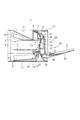
プリンタ1は、図1に示すように、積載されたシートを給送する本体給送部10及び手差し給送部20と、を有している。また、プリンタ1は、本体給送部10又は手差し給送部20によって給送されたシートに画像を形成する画像形成部5と、シートに転写された画像を定着させる定着装置6と、シートを排出トレイ9に排出可能な排出ローラ対8と、を有している。
As shown in FIG. 1, the printer 1 has a main
プリンタ1に画像形成ジョブが出力されると、プリンタ1に接続された外部のコンピュータ等から入力された画像情報に基づいて、画像形成部5による画像形成プロセスが開始される。画像形成部5は、レーザスキャナ52と、感光ドラム51を有するプロセスカートリッジPと、転写ローラ53と、を備えている。感光ドラム51の周囲には、不図示の帯電ローラ及び現像ローラ等が設けられている。感光ドラム51及び転写ローラ53は、転写ニップT1を形成している。
When the image forming job is output to the printer 1, the image forming process by the
レーザスキャナ52は、入力された画像情報に基づいて、感光ドラム51に向けてレーザ光を照射する。このとき感光ドラム51は、帯電ローラにより予め帯電されており、レーザ光が照射されることで感光ドラム51上に静電潜像が形成される。その後、現像ローラによりこの静電潜像が現像され、感光ドラム51上にモノクロのトナー像が形成される。
The
上述の画像形成プロセスに並行して、本体給送部10又は手差し給送部20からシートSが給送される。本体給送部10は、プリンタ1の装置本体1Aに対して引出し及び装着可能なカセット11と、給送ローラ12と、分離ローラ対13と、を有している。カセット11に収容されたシートSは、給送ローラ12によって給送され、給送ローラ12によって給送されたシートSは、分離ローラ対13によって1枚ずつに分離される。また、シート支持装置としての手差し給送部20は、装置本体1Aに回動可能に支持されるカバー25に支持される手差しトレイ24と、給送ローラ21と、分離ローラ対22と、を有している。シート支持部としての手差しトレイ24に支持されたシートSは、給送ローラ21によって給送され、給送ローラ21によって給送されたシートSは、分離ローラ対22によって1枚ずつに分離される。
In parallel with the image forming process described above, the sheet S is fed from the main
なお、カセット11や手差しトレイ24には、シートを支持可能かつ昇降可能な中板を設けてもよく、例えば画像形成ジョブが入力されることによって中板を上昇させ、中板に支持されたシートと給送ローラとを接触させてもよい。また、分離ローラ対13,22は、ローラ対の一方がパッド等でもよく、トルクリミッタ方式やリタードローラ方式等を適用できる。
The
本体給送部10又は手差し給送部20から送り出され、搬送ローラ対32によって搬送されたシートSには、転写ローラ53に印加された静電的負荷バイアスによって、転写ニップT1において感光ドラム51上のトナー像が転写される。感光ドラム51上に残った残トナーは、不図示のクリーニングブレードによって回収される。トナー像が転写されたシートSは、定着装置6の定着フィルム61及び加圧ローラ62によって所定の熱及び圧力が付与されて、トナーが溶融固着(定着)される。定着フィルム61の内部には、セラミックヒータ等の加熱部材が配設されている。定着装置6を通過したシートSは、排出ローラ対8によって排出トレイ9に排出される。
The sheet S, which is sent out from the main
シートSの両面に画像を形成する場合には、第1面に画像が形成されたシートSは、反転ローラ対7によってスイッチバックされて、両面搬送路CPに搬送される。両面搬送路CPは、シートSを搬送ローラ対31に向けて案内する。そして、シートSは、搬送ローラ対31,32によって再び転写ニップT1に搬送され、転写ニップT1において第2面に画像が形成されて排出トレイ9に排出される。
When an image is formed on both sides of the sheet S, the sheet S on which the image is formed on the first surface is switched back by the reversing
[手差し給送部の詳細構成]
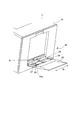
次に、手差し給送部20の詳細構成について説明する。図2に示すように、カバー25は、装置本体1Aに対して開閉可能に支持されており、カバー25には、手差しトレイ24が回動軸24aを中心に昇降可能に支持されている。手差しトレイ24は、手差し給送部20からシートを給送するジョブが入力された際には、不図示の上昇機構によって上昇し、手差しトレイ24に積載された最上位のシートが給送ローラ21に接触する。
[Detailed configuration of the manual feed section]
Next, the detailed configuration of the manual
手差しトレイ24には、図2及び図3(a)に示すように、1対のサイド規制板26,27がシート給送方向に直交する移動方向としての幅方向Wに移動可能に支持されている。手差しトレイ24には、案内溝Lm24,Ln24が形成されており、サイド規制板26,27は、案内溝Lm24,Ln24によって幅方向に案内される。
As shown in FIGS. 2 and 3A, a pair of
また、図3(a)(b)に示すように、サイド規制板26,27は、手差しトレイ24のシート載置面24bとは反対側において、シート載置面幅方向Wに延びるラック部26R,27Rをそれぞれ有している。これらラック部26R,27Rは、ピニオンギア41を介して噛合している。このため、サイド規制板26,27は、幅方向Wにおいて互いに逆方向に連動するように構成されている。
Further, as shown in FIGS. 3A and 3B, the
更に、手差し給送部20は、規制部としてのサイド規制板27を手差しトレイ24に対して位置決めすることで、サイド規制板26,27をロックするための位置決めユニット40を有している。なお、位置決めユニット40は、サイド規制板26を手差しトレイ24に対して位置決めする構成としてもよい。
Further, the manual
[位置決めユニット]
次に、位置決めユニット40について説明する。位置決めユニット40は、図3(b)に示すように、手差しトレイ24に形成される1対のラックギア24L1,24L2と、ロック機構42と、を有している。ラックギア24L1,24L2は、ロック機構42を挟んで互いに対向するように設けられており、それぞれ複数の歯が幅方向Wに配列されている。すなわち、第2歯部としてのラックギア24L2は、幅方向に直交する直交方向Oにおいて第1歯部としてのラックギア24L1とは異なる位置に配置されている。
[Positioning unit]
Next, the
ロック機構42は、図4(a)(b)に示すように、案内溝Ln24(図3(a)参照)を介してサイド規制板27に連結されるアンカーホルダ43と、アンカーホルダ43の保持部43Rに保持されるアンカー44,45と、を有している。また、ロック機構42は、アンカー44,45に連結されるロック解除レバー28と、アンカー44,45の間に張設される圧縮バネ46と、を有している。アンカー44,45は、保持部43Rによって直交方向Oにスライド移動可能に支持されている。
As shown in FIGS. 4A and 4B, the
アンカー44,45には、それぞれカム穴44c,45cが形成されており、カム穴44c,45cには、ロック解除レバー28のボス部28b,28cが挿入されている。アンカー44,45は、圧縮バネ46によって互いに離れる方向に付勢されているが、ロック解除レバー28のボス部28b,28cによってアンカー44,45の移動が規制されている。また、アンカー44,45のカム穴44c,45cは、ボス部28b,28cよりも大きく形成されており、ボス部28b,28cは、カム穴44c,45c内で所定量移動可能になっている。
Cam holes 44c and 45c are formed in the
図4(c)(d)に示すように、ロック解除レバー28を矢印C1方向又矢印C2方向に回転させると、アンカー44,45は、ボス部28b,28cとカム穴44c,45cとの係合によって、圧縮バネ46の付勢力に抗して互いに近づく。アンカー44,45には、後述する歯部44r,45r(図5(a)参照)が形成されており、離間機構としてのロック解除レバー28が回転操作されることで、ラックギア24L1,24L2と歯部44r,45rとのロックが解除される。これにより、サイド規制板27をユーザが移動可能となる。
As shown in FIGS. 4 (c) and 4 (d), when the
なお、付勢部としての圧縮バネ46は、第3歯部としての歯部44rをラックギア24L1に係合するように付勢すると共に、第4歯部としての歯部45rをラックギア24L2に係合するように付勢している。また、歯部44r,45rは、ラックギア24L1,24L2に対して直交方向Oに係合するように構成されている。
The
[アンカーとラックギアの歯形状]
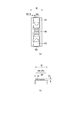
次に、アンカー44,45とラックギア24L1,24L2の歯形状について説明する。アンカー44,45には、図5(a)に示すように、ラックギア24L1,24L2に係合可能な歯部44r,45rが形成されている。歯部44r,45rは、図5(b)に示すように、所定のピッチBfで幅方向Wに並んだ複数の歯をそれぞれ有している。これらの歯は、略直角三角形状を有しており、歯底から歯先までの歯丈は長さHrである。また、図5(a)に示すように、歯部44rと歯部45rの歯は、ピッチBfの半分の距離Bf/2だけ、幅方向Wにおいて互いにずれて配置されている。
[Tooth shape of anchor and rack gear]
Next, the tooth shapes of the
ラックギア24L1,24L2は、図6(b)に示すように、所定のピッチBfで幅方向Wに並んだ複数の歯をそれぞれ有している。これらの歯は、略直角三角形状を有しており、歯底から歯先までの歯丈は長さHfである。また、図6(a)に示すように、ラックギア24L1,24L2の歯は、幅方向Wにおいて互いに同じ位置に配置されている。 As shown in FIG. 6B, the rack gears 24L1 and 24L2 each have a plurality of teeth arranged in the width direction W at a predetermined pitch Bf. These teeth have a substantially right-angled triangular shape, and the tooth length from the tooth base to the tooth tip is the length Hf. Further, as shown in FIG. 6A, the teeth of the rack gears 24L1, 24L2 are arranged at the same positions in the width direction W.
[ロック機構の作用]
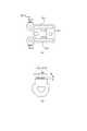
次に、ロック機構42の作用について説明する。図7(a)は、ロック機構42がラックギア24L1,24L2にロックされた状態の一例を示す断面図である。図7(b)は、一方のアンカー44とラックギア24L1の係合部分を示す拡大断面図である。図7(c)は、他方のアンカー45とラックギア24L2の係合部分を示す拡大断面図である。
[Action of lock mechanism]
Next, the operation of the
上述したように、アンカー44,45の歯部44r,45rは距離Bf/2だけ互いにずれて配置されている一方、ラックギア24L1,24L2は幅方向Wにおいて同じ位置に配置されている。このため、歯部44r,45rの両方がラックギア24L1,24L2に対して係合状態となることはない。
As described above, the
例えば、図7(a)〜(c)に示すように、歯部45rがラックギア24L2に係合する係合状態となっている際には、歯部44rはラックギア24L1に対して非係合状態となる。歯部45rの第2係合状態としての係合状態は、歯部45rの歯の歯元までラックギア24L2に係合した状態である。歯部45rの第2非係合状態としての非係合状態は、歯部45rの歯の根元がラックギア24L2に係合していない状態である。すなわち、非係合状態の歯部45rは、係合状態よりもラックギア24L2に対する当接面積が少ない。
For example, as shown in FIGS. 7A to 7C, when the
同様にして、歯部44rの第1係合状態としての係合状態は、歯部44rの歯の歯元までラックギア24L1に係合した状態である。歯部44rの第1非係合状態としての非係合状態は、歯部44rの歯の根元がラックギア24L1に係合していない状態であって、係合状態よりもラックギア24L1に対する当接面積が少ない状態である。このように、歯部44r,45rは、それぞれ係合状態と、非係合状態と、に遷移可能である。
Similarly, the engaged state as the first engaged state of the
図7(b)(c)に示すように、歯部44rが非係合状態となり、歯部45rが係合状態となっている場合、歯部44rはラックギア24L1に対して距離Hr/2ほど浮いた状態となっている。歯部44rがラックギア24L1に対して距離Hr/2ほど浮くことで、アンカー44はアンカー45に近づき、その分だけ圧縮バネ46が圧縮される。そして、圧縮バネ46に蓄積した弾性力により、アンカー45は、ラックギア24L2に対して押し付けられる。
As shown in FIGS. 7B and 7C, when the
すなわち、歯部44rがラックギア24L1から受ける力は、アンカー44,45を連結する圧縮バネ46を介して歯部45rがラックギア24L2に係合する方向の力として作用する。このため、歯部45rとラックギア24L2との間のガタが少なくなって歯部45rとラックギア24L2との係合はより強固なものとなり、サイド規制板26,27を安定して手差しトレイ24に対して位置決めすることができる。サイド規制板26,27が手差しトレイ24に強固に位置決めされることで、シートの整合性が向上し、搬送不良等を低減することができる。
That is, the force received by the
なお、アンカー44,45及び圧縮バネ46は、歯部44rがラックギア24L1から受ける力を歯部45rがラックギア24L2に係合する方向の力として作用させる作用部140を構成している。また、歯部45rが非係合状態の時には、作用部140は、歯部45rがラックギア24L2から受ける力を歯部44rがラックギア24L1に係合する方向の力として作用させる。これにより、歯部44r,45rのいずれがラックギアに係合したとしても、サイド規制板27を手差しトレイ24に対して強固に位置決めすることができる。
The
また、アンカー44,45の歯部44r,45rは距離Bf/2だけ互いにずれて配置されているため、サイド規制板27が幅方向Wに距離Bf/2だけ移動すると、歯部44rが係合状態となり、歯部45rが非係合状態となる。このように、各歯部44r,45rのピッチBfよりも細かい距離Bf/2毎にサイド規制板27を手差しトレイ24に位置決めすることができる。
Further, since the
特に、歯部44r,45rは、加工寸法や機械強度上の限界があり、ピッチBfを小さくすると歯丈も短くなってしまう。歯丈が短くなると歯部44r,45rとラックギア24L1,24L2との係合強度が低下してしまう。そこで、本実施の形態では、ラックギアと歯部を1対ずつ設けると共に、1対の歯部を距離Bf/2だけ互いにずれて配置し、歯部の係合強度は維持しつつより細かくサイド規制板27を位置決めすることができるようになっている。なお、1対のラックギアを距離Bf/2だけ互いにずれて配置し、1対の歯部を幅方向Wにおいて同じ位置に設けてもよい。
In particular, the
<第2の実施の形態>
次いで、本発明の第2の実施の形態について説明するが、第2の実施の形態は、第1の実施の形態のロック機構の構成を変更したものである。このため、第1の実施の形態と同様の構成については、図示を省略、又は図に同一符号を付して説明する。
<Second Embodiment>
Next, the second embodiment of the present invention will be described, but the second embodiment is a modification of the configuration of the locking mechanism of the first embodiment. Therefore, the same configuration as that of the first embodiment will be described by omitting the illustration or adding the same reference numerals to the drawings.
[ロック機構]
本実施の形態に係るロック機構142は、図8(a)(b)に示すように、アンカー部材47と、ロック解除レバー28と、を有している。作用部及び保持部としてのアンカー部材47は、手差しトレイ24に設けられた軸部27dを中心に回動可能に支持されており、薄肉に形成されて弾性変形可能なアンカーアームLr1,Lr2を有している。回動軸としての軸部27dは、幅方向W及び直交方向Oに垂直な方向に延びている。
[Lock mechanism]
As shown in FIGS. 8A and 8B, the
アンカーアームLr1の先端部には、ラックギア24L1に係合可能な第3歯部としての歯部47r1が設けられ、アンカーアームLr2の先端部には、ラックギア24L2に係合可能な第4歯部としての歯部47r2が設けられている。付勢部としてのアンカーアームLr1,Lr2は、歯部47r1,47r2をラックギア24L1,24L2にそれぞれ係合するように付勢している。また、歯部47r1,47r2の両方は、軸部27dの軸方向に視て、幅方向Wにおいて軸部27dの一方側にまとめて配置されている。
The tip of the anchor arm Lr1 is provided with a tooth portion 47r1 as a third tooth portion that can be engaged with the rack gear 24L1, and the tip portion of the anchor arm Lr2 is provided as a fourth tooth portion that can be engaged with the rack gear 24L2. The tooth portion 47r2 is provided. The anchor arms Lr1 and Lr2 as the urging portions urge the tooth portions 47r1 and 47r2 so as to engage with the rack gears 24L1 and 24L2, respectively. Further, both the tooth portions 47r1 and 47r2 are arranged together on one side of the
また、アンカーアームLr1の歯部47r1とは反対側にはカム穴47bが形成され、アンカーアームLr2の歯部47r2とは反対側にはカム穴47cが形成されている。カム穴47b,47cには、ロック解除レバー28のボス部28b,28cが挿入されている。カム穴47b,47cは、ボス部28b,28cよりも大きく形成されており、ボス部28b,28cは、カム穴47b,47c内で所定量移動可能になっている。
Further, a
図8(c)(d)に示すように、ロック解除レバー28を矢印C1方向又は矢印C2方向に回転させると、アンカー部材47のアンカーアームLr1,Lr2は、ボス部28b,28cとカム穴47b,47cとの係合によって、互いに近づく。このようにロック解除レバー28が回転操作されることで、ラックギア24L1,24L2と歯部47r1,47r2とのロックが解除される。これにより、サイド規制板27をユーザが移動可能となる。
As shown in FIGS. 8 (c) and 8 (d), when the
[アンカー部材の歯形状]
次に、アンカー部材47の歯形状について説明する。アンカー部材47には、図9(a)に示すように、ラックギア24L1,24L2に係合可能な歯部47r1,47r2が形成されている。歯部47r1,47r2は、図9(b)に示すように、所定のピッチBfで幅方向Wに並んだ複数の歯をそれぞれ有している。これらの歯は、略直角三角形状を有しており、歯底から歯先までの歯丈は長さHrである。また、図9(a)に示すように、歯部47r1と歯部47r2の歯は、ピッチBfの半分の距離Bf/2だけ、幅方向Wにおいて互いにずれて配置されている。
[Tooth shape of anchor member]
Next, the tooth shape of the
[ロック機構の作用]
次に、ロック機構42の作用について説明する。図10(a)は、ロック機構142がラックギア24L1,24L2にロックされた状態の一例を示す断面図である。図10(b)は、一方のアンカーアームLr1とラックギア24L1の係合部分を示す拡大断面図である。図10(c)は、他方のアンカーアームLr2とラックギア24L2の係合部分を示す拡大断面図である。
[Action of lock mechanism]
Next, the operation of the
上述したように、アンカーアームLr1,Lr2の歯部47r1,47r2は距離Bf/2だけ互いにずれて配置されている一方、ラックギア24L1,24L2は幅方向Wにおいて同じ位置に配置されている。このため、歯部47r1,47r2の両方がラックギア24L1,24L2に対して係合状態となることはない。 As described above, the tooth portions 47r1 and 47r2 of the anchor arms Lr1 and Lr2 are arranged so as to be offset from each other by the distance Bf / 2, while the rack gears 24L1 and 24L2 are arranged at the same position in the width direction W. Therefore, both the tooth portions 47r1 and 47r2 are not engaged with the rack gears 24L1 and 24L2.
図10(a)(b)(c)に示すように、歯部47r1が非係合状態となり、歯部47r2が係合状態となっている場合、歯部47r1はラックギア24L1に対して距離Hr/2ほど浮いた状態となっている。歯部47r1がラックギア24L1に対して距離Hr/2ほど浮くことで、アンカーアームLr1はアンカーアームLr2に近づくように弾性変形する。アンカーアームLr1に発生した弾性力は、アンカー部材47を軸部27dを中心に矢印C3方向に回転させようとする。これにより、アンカーアームLr2に設けられた歯部47r2は、ラックギア24L2に対して押し付けられる。
As shown in FIGS. 10A, 10B, and 10C, when the tooth portion 47r1 is in the disengaged state and the tooth portion 47r2 is in the engaged state, the tooth portion 47r1 has a distance Hr with respect to the rack gear 24L1. It is in a floating state of about / 2. When the tooth portion 47r1 floats with respect to the rack gear 24L1 by a distance of about Hr / 2, the anchor arm Lr1 is elastically deformed so as to approach the anchor arm Lr2. The elastic force generated in the anchor arm Lr1 tends to rotate the
すなわち、歯部47r1がラックギア24L1から受ける力は、アンカー部材47を介して歯部47r2がラックギア24L2に係合する方向の力として作用する。このため、歯部47r2とラックギア24L2との係合はより強固なものとなり、サイド規制板26,27を安定して手差しトレイ24に対して位置決めすることができる。
また、本実施の形態では、1つのアンカー部材47に歯部47r1,47r2の両方を設けているため、部品点数及びコストを削減することができる。
That is, the force received by the tooth portion 47r1 from the rack gear 24L1 acts as a force in the direction in which the tooth portion 47r2 engages with the rack gear 24L2 via the
Further, in the present embodiment, since both the tooth portions 47r1 and 47r2 are provided on one
<第3の実施の形態>
次いで、本発明の第3の実施の形態について説明するが、第3の実施の形態は、第1の実施の形態のロック機構の構成及びラックギアの配置を変更したものである。このため、第1の実施の形態と同様の構成については、図示を省略、又は図に同一符号を付して説明する。
<Third embodiment>
Next, a third embodiment of the present invention will be described. The third embodiment is a modification of the configuration of the locking mechanism and the arrangement of the rack gears of the first embodiment. Therefore, the same configuration as that of the first embodiment will be described by omitting the illustration or adding the same reference numerals to the drawings.
[ロック機構]
本実施の形態に係るロック機構242は、図11(a)(b)に示すように、案内溝Ln24を介してサイド規制板27に連結されるアンカー部材48と、ロック解除レバー28と、を有している。手差しトレイ24に設けられたラックギア24L1,24L2は、案内部としての案内溝Ln24を挟んで幅方向Wに直交する直交方向Oにおいて互いに異なる位置に配置されている。
[Lock mechanism]
As shown in FIGS. 11A and 11B, the
作用部及び保持部としてのアンカー部材48は、薄肉に形成されて弾性変形可能なアンカーアームNr1,Nr2を有している。アンカーアームNr1の先端部には、ラックギア24L1に係合可能な第3歯部としての歯部48r1が設けられ、アンカーアームNr2の先端部には、ラックギア24L2に係合可能な第4歯部としての歯部48r2が設けられている。歯部48r1,48r2は、それぞれラックギア24L1,24L2に対して幅方向W及び直交方向Oに垂直な方向に係合する。付勢部としてのアンカーアームNr1,Nr2は、歯部48r1,48r2をラックギア24L1,24L2にそれぞれ係合するように付勢している。
The
また、アンカーアームNr1にはカム溝48bが形成され、アンカーアームNr2にはカム溝48cが形成されている。カム溝48b,48cには、ロック解除レバー28のボス部28b,28cが係合している。カム溝48b,48cは、図11(c)に示すように、直交方向Oに視て窪んだ溝形状を有しており、ボス部28b,28cは、カム溝48b,48cに係合した状態で幅方向に移動することで、カム溝48b,48cを押圧する。
Further, a
図11(d)(e)に示すように、ロック解除レバー28を矢印C1方向又は矢印C2方向に回転させると、アンカー部材48のアンカーアームNr1,Nr2は、ボス部28b,28cがカム溝48b,48cを押圧する。これにより、アンカーアームNr1,Nr2の歯部48r1,48r2は、ラックギア24L1,24L2から離間し、ラックギア24L1,24L2と歯部48r1,48r2とのロックが解除される。よって、サイド規制板27をユーザが移動可能となる。
As shown in FIGS. 11D and 11E, when the unlocking
[アンカー部材とラックギアの歯形状]
次に、アンカー部材48とラックギア24L1,24L2の歯形状について説明する。アンカー部材48には、図12(a)に示すように、ラックギア24L1,24L2に係合可能な歯部48r1,48r2が形成されている。歯部48r1,48r2は、図12(b)に示すように、所定のピッチBfで幅方向Wに並んだ複数の歯をそれぞれ有している。これらの歯は、略直角三角形状を有しており、歯底から歯先までの歯丈は長さHrである。また、図12(a)に示すように、歯部48r1と歯部48r2の歯は、ピッチBfの半分の距離Bf/2だけ、幅方向Wにおいて互いにずれて配置されている。
[Anchor member and rack gear tooth shape]
Next, the tooth shapes of the
ラックギア24L1,24L2は、図13(b)に示すように、所定のピッチBfで幅方向Wに並んだ複数の歯をそれぞれ有している。これらの歯は、略直角三角形状を有しており、歯底から歯先までの歯丈は長さHfである。また、図13(a)に示すように、ラックギア24L1,24L2の歯は、幅方向Wにおいて互いに同じ位置に配置されている。 As shown in FIG. 13B, the rack gears 24L1 and 24L2 each have a plurality of teeth arranged in the width direction W at a predetermined pitch Bf. These teeth have a substantially right-angled triangular shape, and the tooth length from the tooth base to the tooth tip is the length Hf. Further, as shown in FIG. 13A, the teeth of the rack gears 24L1, 24L2 are arranged at the same positions in the width direction W.
[ロック機構の作用]
次に、ロック機構242の作用について説明する。上述したように、アンカーアームNr1,Nr2の歯部48r1,48r2は距離Bf/2だけ互いにずれて配置されている一方、ラックギア24L1,24L2は幅方向Wにおいて同じ位置に配置されている。このため、歯部48r1,48r2の両方がラックギア24L1,24L2に対して係合状態となることはない。
[Action of lock mechanism]
Next, the operation of the
図14(a)〜(d)に示すように、歯部48r1が非係合状態となり、歯部48r2が係合状態となっている場合、歯部48r1はラックギア24L1に対して距離Hr/2ほど浮いた状態となっている。ここで、図14(a)(b)に示すように、アンカー部材48は、幅方向Wに延びる軸BL24を中心に揺動可能となるように、サイド規制板27に取り付けられている。歯部48r1,48r2は、直交方向Oにおいて軸BL24を挟むように配置されている。
As shown in FIGS. 14A to 14D, when the tooth portion 48r1 is in the disengaged state and the tooth portion 48r2 is in the engaged state, the tooth portion 48r1 has a distance Hr / 2 with respect to the rack gear 24L1. It is in a floating state. Here, as shown in FIGS. 14A and 14B, the
歯部48r1がラックギア24L1に対して距離Hr/2ほど浮くことで、アンカーアームNr1はラックギア24L1から離れる方向に弾性変形する。アンカーアームNr1に発生した弾性力は、アンカー部材48を軸BL24を中心に矢印C4方向に回転させようとする。これにより、アンカーアームNr2に設けられた歯部48r2は、ラックギア24L2に対して押し付けられる。
When the tooth portion 48r1 floats with respect to the rack gear 24L1 by a distance of about Hr / 2, the anchor arm Nr1 elastically deforms in the direction away from the rack gear 24L1. The elastic force generated in the anchor arm Nr1 tends to rotate the
すなわち、歯部48r1がラックギア24L1から受ける力は、アンカー部材48を介して歯部48r2がラックギア24L2に係合する方向の力として作用する。このため、歯部48r2とラックギア24L2との係合はより強固なものとなり、サイド規制板26,27を安定して手差しトレイ24に対して位置決めすることができる。
That is, the force received by the tooth portion 48r1 from the rack gear 24L1 acts as a force in the direction in which the tooth portion 48r2 engages with the rack gear 24L2 via the
また、本実施の形態では、1つのアンカー部材48に歯部48r1,48r2の両方を設けているため、部品点数及びコストを削減することができる。更に、歯部48r1,48r2が、ラックギア24L1,24L2に対して幅方向W及び直交方向Oに垂直なシート積載方向に係合するように構成されているので、ロック機構242をシート積載方向において小型化できる。
Further, in the present embodiment, since both the tooth portions 48r1 and 48r2 are provided on one
なお、既述のいずれの形態においても、1対のラックギアを幅方向Wにおいて同じ位置に配置し、1対の歯部を距離Bf/2だけ互いにずれて配置したが、これに限定されない。例えば、1対のラックギアを幅方向Wにおいて距離Bf/2だけ互いにずれて配置し、1対の歯部を幅方向Wにおいて同じ位置に配置してもよい。 In any of the above-described embodiments, the pair of rack gears are arranged at the same position in the width direction W, and the pair of tooth portions are arranged so as to be offset from each other by a distance Bf / 2, but the present invention is not limited to this. For example, a pair of rack gears may be arranged so as to be offset from each other by a distance Bf / 2 in the width direction W, and a pair of tooth portions may be arranged at the same position in the width direction W.
また、歯のズレ量である距離Bf/2は、適宜変更してもよい。また、1対のラックギア及び1対の歯部に限らず、3列以上のラックギアと3カ所以上の歯部を設けてもよい。 Further, the distance Bf / 2, which is the amount of tooth misalignment, may be appropriately changed. Further, the present invention is not limited to a pair of rack gears and a pair of tooth portions, and three or more rows of rack gears and three or more tooth portions may be provided.
また、既述のいずれの形態においても、手差し給送部20のサイド規制板27を位置決めするために本発明を適用したが、これに限定されない。例えば、シートの後端の位置を規制する後端規制板を設け、後端規制板に本発明を適用してもよく、本体給送部10に本発明を適用してもよい。
Further, in any of the above-described forms, the present invention has been applied to position the
また、既述のいずれの形態においても、電子写真方式のプリンタ1を用いて説明したが、本発明はこれに限定されない。例えば、ノズルからインク液を吐出させることでシートに画像を形成するインクジェット方式の画像形成装置にも本発明を適用することが可能である。 Moreover, although the description has been made using the electrophotographic printer 1 in any of the above-described forms, the present invention is not limited to this. For example, the present invention can be applied to an inkjet image forming apparatus that forms an image on a sheet by ejecting an ink liquid from a nozzle.
1:画像形成装置(プリンタ)/5:画像形成部/20:シート支持装置(手差し給送部)/24:シート支持部(手差しトレイ)/24L1:第1歯部(ラックギア)/24L2:第2歯部(ラックギア)/27:規制部(サイド規制板)/27d:回動軸(軸部)/28:離間機構(ロック解除レバー)/40:位置決めユニット/44r,47r1,48r1:第3歯部(歯部)/45r,47r2,48r2:第4歯部(歯部)/46:付勢部(圧縮バネ)/47:作用部、保持部(アンカー部材)/48:作用部、保持部(アンカー部材)/140:作用部/Bf:所定のピッチ/BL24:軸/Ln24:案内部(案内溝)/Lr1,Lr2:付勢部(アンカーアーム)/Nr1,Nr2:付勢部(アンカーアーム)/O:直交方向/W:移動方向(幅方向) 1: Image forming device (printer) / 5: Image forming part / 20: Seat support device (manual feed feeding part) / 24: Seat support part (manual feed tray) / 24L 1: First tooth part (rack gear) / 24L2: No. 2 tooth part (rack gear) / 27: regulation part (side regulation plate) / 27d: rotation shaft (shaft part) / 28: separation mechanism (lock release lever) / 40: positioning unit / 44r, 47r1, 48r1: 3rd Tooth (tooth) / 45r, 47r2, 48r2: 4th tooth (tooth) / 46: Toothing (compression spring) / 47: Acting part, holding part (anchor member) / 48: Acting part, holding Part (anchor member) / 140: Action part / Bf: Predetermined pitch / BL24: Shaft / Ln24: Guide part (guide groove) / Lr1, Lr2: Biasing part (anchor arm) / Nr1, Nr2: Bending part ( Anchor arm) / O: Orthogonal direction / W: Moving direction (width direction)
Claims (9)
前記シート支持部に移動可能に支持され、前記シート支持部に支持されたシートの位置を規制する規制部と、
前記規制部を前記シート支持部に対して位置決めする位置決めユニットと、を備え、
前記位置決めユニットは、
前記規制部の移動方向に沿って前記シート支持部に設けられ、複数の歯が配列される第1歯部と、
前記移動方向に直交する直交方向において前記第1歯部とは異なる位置に配置されると共に前記移動方向に沿って前記シート支持部に設けられ、複数の歯が配列される第2歯部と、
前記規制部に支持され、かつ前記第1歯部に係合する第1係合状態と、前記第1係合状態よりも前記第1歯部に対する当接面積が少ない第1非係合状態と、に遷移可能な第3歯部と、
前記規制部に支持され、かつ前記第2歯部に係合する第2係合状態と、前記第2係合状態よりも前記第2歯部に対する当接面積が少ない第2非係合状態と、に遷移可能な第4歯部と、
前記第3歯部が前記第1係合状態かつ前記第4歯部が前記第2非係合状態の場合に、前記第4歯部が前記第2歯部から受ける力を前記第3歯部が前記第1歯部に係合する方向の力として作用させ、前記第4歯部が前記第2係合状態かつ前記第3歯部が前記第1非係合状態の場合に、前記第3歯部が前記第1歯部から受ける力を前記第4歯部が前記第2歯部に係合する方向の力として作用させる作用部と、を有する、
ことを特徴とするシート支持装置。 The seat support part that supports the seat and
A regulatory unit that is movably supported by the seat support and regulates the position of the seat supported by the seat support.
A positioning unit for positioning the regulating portion with respect to the seat support portion is provided.
The positioning unit is
A first tooth portion provided on the seat support portion along the moving direction of the restricting portion and in which a plurality of teeth are arranged, and a first tooth portion.
A second tooth portion that is arranged at a position different from the first tooth portion in an orthogonal direction orthogonal to the moving direction and is provided on the seat support portion along the moving direction and in which a plurality of teeth are arranged.
A first engaged state supported by the restricting portion and engaged with the first tooth portion, and a first disengaged state in which the contact area with the first tooth portion is smaller than that of the first engaged state. The third tooth that can be transitioned to, and
A second engaged state supported by the restricting portion and engaged with the second tooth portion, and a second disengaged state in which the contact area with the second tooth portion is smaller than that of the second engaged state. The 4th tooth that can be transitioned to, and
When the third tooth portion is in the first engaged state and the fourth tooth portion is in the second disengaged state, the force received by the fourth tooth portion from the second tooth portion is applied to the third tooth portion. Acts as a force in the direction of engaging with the first tooth portion, and when the fourth tooth portion is in the second engaged state and the third tooth portion is in the first disengaged state, the third tooth portion. It has an action portion that causes the force received by the tooth portion from the first tooth portion to act as a force in the direction in which the fourth tooth portion engages with the second tooth portion.
A seat support device characterized by the fact that.
ことを特徴とする請求項1に記載のシート支持装置。 The seat support portion is arranged between the first tooth portion and the second tooth portion in the orthogonal direction, and has a guide portion that guides the regulation portion in the movement direction.
The seat support device according to claim 1.
前記第4歯部は、前記所定のピッチで前記移動方向に並ぶと共に、前記第3歯部の複数の歯に対して前記所定のピッチの半分だけ前記移動方向にずれて配置される複数の歯を有し、
前記第1歯部及び前記第2歯部の複数の歯は、前記移動方向において互いに同じ位置に配置される、
ことを特徴とする請求項1又は2に記載のシート支持装置。 The third tooth portion has a plurality of teeth arranged in the moving direction at a predetermined pitch.
The fourth tooth portion is arranged in the moving direction at the predetermined pitch, and the plurality of teeth are arranged so as to be offset in the moving direction by half of the predetermined pitch with respect to the plurality of teeth of the third tooth portion. Have,
The plurality of teeth of the first tooth portion and the second tooth portion are arranged at the same position with each other in the moving direction.
The seat support device according to claim 1 or 2.
ことを特徴とする請求項1乃至3のいずれか1項に記載のシート支持装置。 The working portion urges the third tooth portion to engage with the first tooth portion and the fourth tooth portion to engage with the second tooth portion. Have,
The seat support device according to any one of claims 1 to 3, wherein the seat support device is characterized by the above.
前記付勢部は、前記直交方向において前記第3歯部及び前記第4歯部との間に配置される圧縮バネである、
ことを特徴とする請求項4に記載のシート支持装置。 The third tooth portion and the fourth tooth portion are supported so as to be slidable in the orthogonal direction, and are engaged with the first tooth portion and the second tooth portion in the orthogonal direction, respectively.
The urging portion is a compression spring arranged between the third tooth portion and the fourth tooth portion in the orthogonal direction.
The seat support device according to claim 4.
前記第3歯部及び前記第4歯部は、それぞれ前記第1歯部及び前記第2歯部に対して前記直交方向に係合し、前記回動軸の軸方向に視て、前記移動方向において前記回動軸の一方側に配置される、
ことを特徴とする請求項1乃至4のいずれか1項に記載のシート支持装置。 The working portion holds the third tooth portion and the fourth tooth portion, and is rotatably supported by the regulating portion about a rotation axis extending in a direction perpendicular to the moving direction and the orthogonal direction. Has a holding part
The third tooth portion and the fourth tooth portion engage with the first tooth portion and the second tooth portion in the orthogonal direction, respectively, and when viewed in the axial direction of the rotation shaft, the moving direction. Is arranged on one side of the rotation shaft in
The seat support device according to any one of claims 1 to 4.
ことを特徴とする請求項1乃至6のいずれか1項に記載のシート支持装置。 A separation mechanism for separating the third tooth portion and the fourth tooth portion from the first tooth portion and the second tooth portion, respectively, is provided.
The seat support device according to any one of claims 1 to 6 , wherein the seat support device is characterized.
ことを特徴とする請求項1乃至7のいずれか1項に記載のシート支持装置。 The moving direction is a direction orthogonal to the sheet feeding direction.
The seat support device according to any one of claims 1 to 7.
前記シート支持装置から給送されたシートに画像を形成する画像形成部と、を備える、
ことを特徴とする画像形成装置。 The seat support device according to any one of claims 1 to 8.
An image forming unit for forming an image on a sheet fed from the sheet supporting device is provided.
An image forming apparatus characterized in that.
Priority Applications (3)
| Application Number | Priority Date | Filing Date | Title |
|---|---|---|---|
| JP2019010374A JP6929311B2 (en) | 2019-01-24 | 2019-01-24 | Seat support device and image forming device |
| US16/733,503 US11492218B2 (en) | 2019-01-24 | 2020-01-03 | Sheet supporting apparatus and image forming apparatus |
| CN202010073307.XA CN111474836B (en) | 2019-01-24 | 2020-01-22 | Sheet supporting device and image forming apparatus |
Applications Claiming Priority (1)
| Application Number | Priority Date | Filing Date | Title |
|---|---|---|---|
| JP2019010374A JP6929311B2 (en) | 2019-01-24 | 2019-01-24 | Seat support device and image forming device |
Publications (2)
| Publication Number | Publication Date |
|---|---|
| JP2020117364A JP2020117364A (en) | 2020-08-06 |
| JP6929311B2 true JP6929311B2 (en) | 2021-09-01 |
Family
ID=71733329
Family Applications (1)
| Application Number | Title | Priority Date | Filing Date |
|---|---|---|---|
| JP2019010374A Active JP6929311B2 (en) | 2019-01-24 | 2019-01-24 | Seat support device and image forming device |
Country Status (3)
| Country | Link |
|---|---|
| US (1) | US11492218B2 (en) |
| JP (1) | JP6929311B2 (en) |
| CN (1) | CN111474836B (en) |
Families Citing this family (1)
| Publication number | Priority date | Publication date | Assignee | Title |
|---|---|---|---|---|
| JP2022077631A (en) * | 2020-11-12 | 2022-05-24 | ブラザー工業株式会社 | Sheet conveying device |
Family Cites Families (13)
| Publication number | Priority date | Publication date | Assignee | Title |
|---|---|---|---|---|
| JP2000335788A (en) * | 1999-05-27 | 2000-12-05 | Canon Inc | Sheet feeding device and image forming device |
| US8052141B2 (en) * | 2007-05-31 | 2011-11-08 | Ricoh Company, Limited | Recording-medium storage device and image forming apparatus |
| JP5023910B2 (en) * | 2007-09-18 | 2012-09-12 | セイコーエプソン株式会社 | Paper guide device |
| JP5012352B2 (en) * | 2007-09-18 | 2012-08-29 | セイコーエプソン株式会社 | Paper guide device |
| US8002270B2 (en) * | 2008-05-29 | 2011-08-23 | Lexmark International, Inc. | Media tray with media restraint assembly adjustable between and lockable at multiple closely spaced positions |
| JP5476970B2 (en) * | 2009-12-15 | 2014-04-23 | 富士ゼロックス株式会社 | Sheet material supply apparatus and image forming apparatus |
| TWI513595B (en) * | 2013-05-17 | 2015-12-21 | Avision Inc | Sheet storage device and sheet processing apparatus using such device |
| JP6048760B2 (en) * | 2014-07-02 | 2016-12-21 | コニカミノルタ株式会社 | Paper feed tray |
| JP6019086B2 (en) * | 2014-10-29 | 2016-11-02 | 京セラドキュメントソリューションズ株式会社 | Paper feeding device and image forming apparatus |
| JP6459567B2 (en) | 2015-01-30 | 2019-01-30 | コニカミノルタ株式会社 | Paper cassette and image forming apparatus |
| US9840382B2 (en) | 2015-04-13 | 2017-12-12 | Canon Kabushiki Kaisha | Sheet supporting apparatus and image forming apparatus |
| US9580258B1 (en) * | 2016-03-04 | 2017-02-28 | Lexmark International, Inc. | Removable media tray having a media restraint with sliding cams and pivoting latching cams operable without the use of pinching |
| JP6942524B2 (en) * | 2017-05-31 | 2021-09-29 | キヤノン株式会社 | Sheet loading device and image forming device |
-
2019
- 2019-01-24 JP JP2019010374A patent/JP6929311B2/en active Active
-
2020
- 2020-01-03 US US16/733,503 patent/US11492218B2/en active Active
- 2020-01-22 CN CN202010073307.XA patent/CN111474836B/en active Active
Also Published As
| Publication number | Publication date |
|---|---|
| US20200239255A1 (en) | 2020-07-30 |
| JP2020117364A (en) | 2020-08-06 |
| US11492218B2 (en) | 2022-11-08 |
| CN111474836B (en) | 2023-08-08 |
| CN111474836A (en) | 2020-07-31 |
Similar Documents
| Publication | Publication Date | Title |
|---|---|---|
| JP5058740B2 (en) | Sheet feeding apparatus and image forming apparatus | |
| JP5818421B2 (en) | Unit moving device and image forming apparatus | |
| JP5534736B2 (en) | Image forming apparatus | |
| JP6929311B2 (en) | Seat support device and image forming device | |
| JP2020183294A (en) | Sheet storage device and image formation device | |
| JP5925162B2 (en) | Sheet feeding apparatus and image forming apparatus | |
| JP2015182836A (en) | Tray for loading recording material, and image forming apparatus | |
| CN107976886B (en) | Sheet supporting device and image forming apparatus | |
| JP2008184297A (en) | Sheet feeder and image forming apparatus | |
| JP6261288B2 (en) | Image forming apparatus | |
| JP2011059260A5 (en) | ||
| JP6521679B2 (en) | Sheet stacking apparatus, sheet feeding apparatus, and image forming apparatus | |
| JP6394523B2 (en) | Manual sheet feeding apparatus and image forming apparatus having the same | |
| JP2017124909A (en) | Shee feeding device and image formation apparatus | |
| JP6677014B2 (en) | Image forming device | |
| JP6252844B2 (en) | Sheet feeding device and image forming apparatus | |
| US20220315363A1 (en) | Sheet feeding apparatus and image forming apparatus | |
| JP7471805B2 (en) | Sheet feeding device and image forming apparatus | |
| JP6821485B2 (en) | Media guide mechanism and image forming device | |
| JP2006103933A (en) | Sheet feeder and image forming device | |
| JP2007076887A (en) | Sheet feeding device and image forming device | |
| JP2018122994A (en) | Sheet support device and image formation device | |
| JP4819622B2 (en) | Sheet feeding apparatus and image forming apparatus | |
| JP2021178724A (en) | Sheet storage device, and image formation device comprising sheet storage device | |
| JP2007168981A (en) | Paper feeding cassette |
Legal Events
| Date | Code | Title | Description |
|---|---|---|---|
| A621 | Written request for application examination |
Free format text: JAPANESE INTERMEDIATE CODE: A621 Effective date: 20191119 |
|
| RD02 | Notification of acceptance of power of attorney |
Free format text: JAPANESE INTERMEDIATE CODE: A7422 Effective date: 20200206 |
|
| RD04 | Notification of resignation of power of attorney |
Free format text: JAPANESE INTERMEDIATE CODE: A7424 Effective date: 20200207 |
|
| A977 | Report on retrieval |
Free format text: JAPANESE INTERMEDIATE CODE: A971007 Effective date: 20201225 |
|
| A131 | Notification of reasons for refusal |
Free format text: JAPANESE INTERMEDIATE CODE: A131 Effective date: 20210202 |
|
| A521 | Request for written amendment filed |
Free format text: JAPANESE INTERMEDIATE CODE: A523 Effective date: 20210402 |
|
| TRDD | Decision of grant or rejection written | ||
| A01 | Written decision to grant a patent or to grant a registration (utility model) |
Free format text: JAPANESE INTERMEDIATE CODE: A01 Effective date: 20210706 |
|
| A61 | First payment of annual fees (during grant procedure) |
Free format text: JAPANESE INTERMEDIATE CODE: A61 Effective date: 20210810 |
|
| R151 | Written notification of patent or utility model registration |
Ref document number: 6929311 Country of ref document: JP Free format text: JAPANESE INTERMEDIATE CODE: R151 |