JP6929233B2 - Delivery system and method for delivering material to the target site - Google Patents
Delivery system and method for delivering material to the target site Download PDFInfo
- Publication number
- JP6929233B2 JP6929233B2 JP2017566755A JP2017566755A JP6929233B2 JP 6929233 B2 JP6929233 B2 JP 6929233B2 JP 2017566755 A JP2017566755 A JP 2017566755A JP 2017566755 A JP2017566755 A JP 2017566755A JP 6929233 B2 JP6929233 B2 JP 6929233B2
- Authority
- JP
- Japan
- Prior art keywords
- delivery device
- target site
- delivery
- virtual boundary
- opening
- Prior art date
- Legal status (The legal status is an assumption and is not a legal conclusion. Google has not performed a legal analysis and makes no representation as to the accuracy of the status listed.)
- Active
Links
Images


Classifications
-
- A—HUMAN NECESSITIES
- A61—MEDICAL OR VETERINARY SCIENCE; HYGIENE
- A61B—DIAGNOSIS; SURGERY; IDENTIFICATION
- A61B34/00—Computer-aided surgery; Manipulators or robots specially adapted for use in surgery
- A61B34/30—Surgical robots
- A61B34/32—Surgical robots operating autonomously
-
- A—HUMAN NECESSITIES
- A61—MEDICAL OR VETERINARY SCIENCE; HYGIENE
- A61B—DIAGNOSIS; SURGERY; IDENTIFICATION
- A61B17/00—Surgical instruments, devices or methods, e.g. tourniquets
- A61B17/56—Surgical instruments or methods for treatment of bones or joints; Devices specially adapted therefor
- A61B17/58—Surgical instruments or methods for treatment of bones or joints; Devices specially adapted therefor for osteosynthesis, e.g. bone plates, screws, setting implements or the like
- A61B17/88—Osteosynthesis instruments; Methods or means for implanting or extracting internal or external fixation devices
- A61B17/8802—Equipment for handling bone cement or other fluid fillers
- A61B17/8805—Equipment for handling bone cement or other fluid fillers for introducing fluid filler into bone or extracting it
-
- A—HUMAN NECESSITIES
- A61—MEDICAL OR VETERINARY SCIENCE; HYGIENE
- A61B—DIAGNOSIS; SURGERY; IDENTIFICATION
- A61B34/00—Computer-aided surgery; Manipulators or robots specially adapted for use in surgery
- A61B34/20—Surgical navigation systems; Devices for tracking or guiding surgical instruments, e.g. for frameless stereotaxis
-
- A—HUMAN NECESSITIES
- A61—MEDICAL OR VETERINARY SCIENCE; HYGIENE
- A61B—DIAGNOSIS; SURGERY; IDENTIFICATION
- A61B34/00—Computer-aided surgery; Manipulators or robots specially adapted for use in surgery
- A61B34/30—Surgical robots
-
- A—HUMAN NECESSITIES
- A61—MEDICAL OR VETERINARY SCIENCE; HYGIENE
- A61B—DIAGNOSIS; SURGERY; IDENTIFICATION
- A61B34/00—Computer-aided surgery; Manipulators or robots specially adapted for use in surgery
- A61B34/70—Manipulators specially adapted for use in surgery
-
- A—HUMAN NECESSITIES
- A61—MEDICAL OR VETERINARY SCIENCE; HYGIENE
- A61B—DIAGNOSIS; SURGERY; IDENTIFICATION
- A61B34/00—Computer-aided surgery; Manipulators or robots specially adapted for use in surgery
- A61B34/70—Manipulators specially adapted for use in surgery
- A61B34/76—Manipulators having means for providing feel, e.g. force or tactile feedback
-
- A—HUMAN NECESSITIES
- A61—MEDICAL OR VETERINARY SCIENCE; HYGIENE
- A61B—DIAGNOSIS; SURGERY; IDENTIFICATION
- A61B90/00—Instruments, implements or accessories specially adapted for surgery or diagnosis and not covered by any of the groups A61B1/00 - A61B50/00, e.g. for luxation treatment or for protecting wound edges
- A61B90/03—Automatic limiting or abutting means, e.g. for safety
-
- A—HUMAN NECESSITIES
- A61—MEDICAL OR VETERINARY SCIENCE; HYGIENE
- A61B—DIAGNOSIS; SURGERY; IDENTIFICATION
- A61B90/00—Instruments, implements or accessories specially adapted for surgery or diagnosis and not covered by any of the groups A61B1/00 - A61B50/00, e.g. for luxation treatment or for protecting wound edges
- A61B90/36—Image-producing devices or illumination devices not otherwise provided for
- A61B90/361—Image-producing devices, e.g. surgical cameras
-
- A—HUMAN NECESSITIES
- A61—MEDICAL OR VETERINARY SCIENCE; HYGIENE
- A61M—DEVICES FOR INTRODUCING MEDIA INTO, OR ONTO, THE BODY; DEVICES FOR TRANSDUCING BODY MEDIA OR FOR TAKING MEDIA FROM THE BODY; DEVICES FOR PRODUCING OR ENDING SLEEP OR STUPOR
- A61M5/00—Devices for bringing media into the body in a subcutaneous, intra-vascular or intramuscular way; Accessories therefor, e.g. filling or cleaning devices, arm-rests
- A61M5/14—Infusion devices, e.g. infusing by gravity; Blood infusion; Accessories therefor
- A61M5/168—Means for controlling media flow to the body or for metering media to the body, e.g. drip meters, counters ; Monitoring media flow to the body
- A61M5/172—Means for controlling media flow to the body or for metering media to the body, e.g. drip meters, counters ; Monitoring media flow to the body electrical or electronic
-
- A—HUMAN NECESSITIES
- A61—MEDICAL OR VETERINARY SCIENCE; HYGIENE
- A61B—DIAGNOSIS; SURGERY; IDENTIFICATION
- A61B34/00—Computer-aided surgery; Manipulators or robots specially adapted for use in surgery
- A61B34/10—Computer-aided planning, simulation or modelling of surgical operations
- A61B2034/107—Visualisation of planned trajectories or target regions
-
- A—HUMAN NECESSITIES
- A61—MEDICAL OR VETERINARY SCIENCE; HYGIENE
- A61B—DIAGNOSIS; SURGERY; IDENTIFICATION
- A61B34/00—Computer-aided surgery; Manipulators or robots specially adapted for use in surgery
- A61B34/20—Surgical navigation systems; Devices for tracking or guiding surgical instruments, e.g. for frameless stereotaxis
- A61B2034/2046—Tracking techniques
- A61B2034/2051—Electromagnetic tracking systems
-
- A—HUMAN NECESSITIES
- A61—MEDICAL OR VETERINARY SCIENCE; HYGIENE
- A61B—DIAGNOSIS; SURGERY; IDENTIFICATION
- A61B34/00—Computer-aided surgery; Manipulators or robots specially adapted for use in surgery
- A61B34/20—Surgical navigation systems; Devices for tracking or guiding surgical instruments, e.g. for frameless stereotaxis
- A61B2034/2046—Tracking techniques
- A61B2034/2055—Optical tracking systems
-
- A—HUMAN NECESSITIES
- A61—MEDICAL OR VETERINARY SCIENCE; HYGIENE
- A61B—DIAGNOSIS; SURGERY; IDENTIFICATION
- A61B34/00—Computer-aided surgery; Manipulators or robots specially adapted for use in surgery
- A61B34/20—Surgical navigation systems; Devices for tracking or guiding surgical instruments, e.g. for frameless stereotaxis
- A61B2034/2046—Tracking techniques
- A61B2034/2059—Mechanical position encoders
-
- A—HUMAN NECESSITIES
- A61—MEDICAL OR VETERINARY SCIENCE; HYGIENE
- A61B—DIAGNOSIS; SURGERY; IDENTIFICATION
- A61B34/00—Computer-aided surgery; Manipulators or robots specially adapted for use in surgery
- A61B34/20—Surgical navigation systems; Devices for tracking or guiding surgical instruments, e.g. for frameless stereotaxis
- A61B2034/2046—Tracking techniques
- A61B2034/2063—Acoustic tracking systems, e.g. using ultrasound
-
- A—HUMAN NECESSITIES
- A61—MEDICAL OR VETERINARY SCIENCE; HYGIENE
- A61B—DIAGNOSIS; SURGERY; IDENTIFICATION
- A61B34/00—Computer-aided surgery; Manipulators or robots specially adapted for use in surgery
- A61B34/30—Surgical robots
- A61B2034/301—Surgical robots for introducing or steering flexible instruments inserted into the body, e.g. catheters or endoscopes
-
- A—HUMAN NECESSITIES
- A61—MEDICAL OR VETERINARY SCIENCE; HYGIENE
- A61B—DIAGNOSIS; SURGERY; IDENTIFICATION
- A61B34/00—Computer-aided surgery; Manipulators or robots specially adapted for use in surgery
- A61B34/25—User interfaces for surgical systems
-
- A—HUMAN NECESSITIES
- A61—MEDICAL OR VETERINARY SCIENCE; HYGIENE
- A61M—DEVICES FOR INTRODUCING MEDIA INTO, OR ONTO, THE BODY; DEVICES FOR TRANSDUCING BODY MEDIA OR FOR TAKING MEDIA FROM THE BODY; DEVICES FOR PRODUCING OR ENDING SLEEP OR STUPOR
- A61M2205/00—General characteristics of the apparatus
- A61M2205/33—Controlling, regulating or measuring
- A61M2205/3331—Pressure; Flow
- A61M2205/3334—Measuring or controlling the flow rate
-
- A—HUMAN NECESSITIES
- A61—MEDICAL OR VETERINARY SCIENCE; HYGIENE
- A61M—DEVICES FOR INTRODUCING MEDIA INTO, OR ONTO, THE BODY; DEVICES FOR TRANSDUCING BODY MEDIA OR FOR TAKING MEDIA FROM THE BODY; DEVICES FOR PRODUCING OR ENDING SLEEP OR STUPOR
- A61M2210/00—Anatomical parts of the body
- A61M2210/02—Bones
-
- A—HUMAN NECESSITIES
- A61—MEDICAL OR VETERINARY SCIENCE; HYGIENE
- A61M—DEVICES FOR INTRODUCING MEDIA INTO, OR ONTO, THE BODY; DEVICES FOR TRANSDUCING BODY MEDIA OR FOR TAKING MEDIA FROM THE BODY; DEVICES FOR PRODUCING OR ENDING SLEEP OR STUPOR
- A61M5/00—Devices for bringing media into the body in a subcutaneous, intra-vascular or intramuscular way; Accessories therefor, e.g. filling or cleaning devices, arm-rests
- A61M5/14—Infusion devices, e.g. infusing by gravity; Blood infusion; Accessories therefor
- A61M5/142—Pressure infusion, e.g. using pumps
Description
[関連出願の相互参照]
本願は、2015年6月23日に出願された米国仮特許出願第62/183,374号の利得を主張するものであり、その開示内容は、参照することによって、その全体がここに含まれるものとする。
[Cross-reference of related applications]
The present application claims the gains of US Provisional Patent Application No. 62 / 183,374 filed June 23, 2015, the disclosure of which is hereby incorporated by reference in its entirety. It shall be.
[発明の分野]
本発明は、一般的に、材料を目標部位に送達するための送達システム及び方法に関する。
[Field of invention]
The present invention generally relates to delivery systems and methods for delivering material to a target site.
材料を目標部位に送達するための送達システム及び方法は、当技術分野において知られている。1つのこのような送達システムとして、目標部位に送達される材料が通る複数のノズルを有するプリントヘッドが挙げられる。ロボットアームが、プリントヘッドを目標部位に対して位置決めする。プリントヘッドは、該プリントヘッドが適所にあるに材料をノズルを通して目標部位に送達する。 Delivery systems and methods for delivering material to a target site are known in the art. One such delivery system includes a printhead with multiple nozzles through which the material delivered to the target site passes. The robot arm positions the printhead with respect to the target site. The printhead delivers the material through the nozzles to the target site where the printhead is in place.
他の送達システムは、生物学的材料を目標部位に投与するように構成された送達装置を備えている。位置決めシステムが、目標部位及び送達装置を互いに位置決めする。リボンが、目標部位に送達される生物学的材料を含んでいる。送達装置は、レーザーを放出し、生物学的材料をリボンから目標部位に送達する。 Other delivery systems include delivery devices configured to administer biological material to the target site. The positioning system positions the target site and the delivery device with each other. The ribbon contains the biological material delivered to the target site. The delivery device emits a laser to deliver the biological material from the ribbon to the target site.
しかし、医療処置中に、材料を目標部位に対して所望のパターン、所望の流量等を維持しながら送達することを目的とし、患者の移動を調整するために、患者の目標部位の位置を追跡すると共に、送達装置の位置を追跡し、目標部位に対する送達装置の位置を維持することが必要とされている。 However, during a medical procedure, the location of the patient's target site is tracked to coordinate patient movement with the aim of delivering the material to the target site while maintaining the desired pattern, desired flow rate, etc. At the same time, it is necessary to track the position of the delivery device and maintain the position of the delivery device with respect to the target site.
材料を目標部位に送達するためのシステムの一実施形態が提供される。この送達システムは、開口を有する送達装置を備え、該送達装置は、材料を開口を通して目標部位に送達するように構成されている。ナビゲーションシステムが、送達装置及び目標部位を追跡し、位置信号を生成するように構成されている。制御装置が、送達装置及びナビゲーションシステムと通信している。制御装置は、目標部位に関連付けられた仮想境界を画定するように、かつナビゲーションシステムからの位置信号に基づき仮想境界に対する開口の移動を制御するように、構成されている。 An embodiment of a system for delivering material to a target site is provided. The delivery system comprises a delivery device having an opening, which delivery device is configured to deliver the material through the opening to the target site. A navigation system is configured to track the delivery device and target site and generate a position signal. The control device is communicating with the delivery device and the navigation system. The control device is configured to define a virtual boundary associated with the target site and to control the movement of the aperture relative to the virtual boundary based on a position signal from the navigation system.
材料を仮想境界によって画定された目標部位に送達するための送達システムの一実施形態が提供される。この送達システムは、材料を目標部位に送達するための開口を有する送達装置を備えている。把持部分が、開口に対して固定されている。把持部分は、開口を目標部位に対して移動させるためにオペレータによって把持されるようになっている。ナビゲーションシステムが、送達装置及び目標部位を追跡し、位置信号を生成するように構成されている。制御装置が、ナビゲーションシステムと電気的に通信している。材料供給装置が、材料を送達装置に供給するようになっている。材料供給装置は、ナビゲーションシステムからの位置信号に基づき、材料が送達装置によって目標部位に送達される比率を制御するために、制御装置と電気的に通信している。 An embodiment of a delivery system for delivering material to a target site defined by a virtual boundary is provided. The delivery system comprises a delivery device having an opening for delivering the material to the target site. The grip portion is fixed to the opening. The grip portion is adapted to be gripped by the operator in order to move the opening relative to the target site. A navigation system is configured to track the delivery device and target site and generate a position signal. The control device is communicating electrically with the navigation system. The material supply device is designed to supply the material to the delivery device. The material supply device is in electrical communication with the control device to control the rate at which the material is delivered to the target site by the delivery device based on the position signal from the navigation system.
材料を送達装置の開口を通して仮想境界によって画定された目標部位に送達するための方法の一実施形態が提供される。この方法は、材料を開口を通して目標部位に送達するステップを含んでいる。送達装置及び目標部位を追跡し、位置信号を生成するようになっている。材料を目標部位に送達している間に、位置信号に基づき仮想境界に対する開口の移動を制御されるようになっている。 One embodiment of a method for delivering material to a target site defined by a virtual boundary through an opening in a delivery device is provided. The method comprises the step of delivering the material through the opening to the target site. It is designed to track the delivery device and target site and generate a position signal. While delivering the material to the target site, the movement of the aperture with respect to the virtual boundary is controlled based on the position signal.
材料を送達装置の開口を通して仮想境界によって画定された目標部位に送達するための方法の他の実施形態が提供される。この方法は、材料を開口を通して目標部位に送達するステップを含んでいる。送達装置及び目標部位を追跡し、位置信号を生成するようになっている。材料を目標部位に送達している間に、位置信号に基づき材料の流量を制御するようになっている。 Other embodiments of methods for delivering material to a target site defined by a virtual boundary through an opening in a delivery device are provided. The method comprises the step of delivering the material through the opening to the target site. It is designed to track the delivery device and target site and generate a position signal. While delivering the material to the target site, the flow rate of the material is controlled based on the position signal.
これらの実施形態の1つの利点は、材料を目標部位に送達している間に、送達装置及び仮想境界の両方を追跡し、ナビゲーションシステムからの位置信号に基づき、目標部位に対する開口の移動及び/又は材料の流量を制御する能力にある。同様に、送達される材料が追跡されてもよい。さらに、仮想境界は、送達装置、すなわち、その開口及び/又は材料を仮想境界内に拘束することによって、目標部位への材料の正確な送達をもたらすことになる。本明細書に記載される送達システム及び方法は、本明細書に具体的に列挙されない他の実施形態をもたらすこともできる。 One advantage of these embodiments is that while the material is being delivered to the target site, both the delivery device and the virtual boundary are tracked, and the movement of the opening relative to the target site and / or based on the position signal from the navigation system. Or it has the ability to control the flow rate of the material. Similarly, the material to be delivered may be tracked. In addition, the virtual boundary will result in accurate delivery of the material to the target site by constraining the delivery device, i.e. its opening and / or material within the virtual boundary. The delivery systems and methods described herein can also result in other embodiments not specifically listed herein.
本発明の利点は、添付の図面に関連して以下の詳細な説明を参照することによって本発明がよく理解されたなら、容易に分かるだろう。 The advantages of the present invention will be readily apparent if the invention is well understood by reference to the following detailed description in connection with the accompanying drawings.
図面を参照すると、図1において送達システムが総称的に10で示されている。なお、いくつかの図を通して、同様の番号は、同様の部品又は対応する部品を示している。 With reference to the drawings, delivery systems are collectively indicated by 10 in FIG. In addition, through some figures, similar numbers indicate similar parts or corresponding parts.
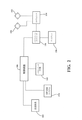
図1および図2を参照すると、一実施形態による送達システム10は、送達器具100、送達装置102、複数のアクチュエータ120,122,124、例えば、モータ、ナビゲーション(ローカライゼーション)システム104、制御装置106、及び材料供給システム170を備えている。ナビゲーションシステム104は、送達装置102の遠位端チップ108を仮想境界110に対して所望の関係に維持するために、送達装置102を追跡するようになっている(本明細書において、「遠位側」という用語は、送達装置102を支持するオペレータから離れて、仮想境界110に向う方を意味している)。患者の目標部位112は、仮想境界110によって画定されている。図1の送達器具100は、オペレータに把持される手持ち式装置である。送達器具100は、ナビゲーションシステム104、制御装置106、及び材料供給システム170のいずれかと無線通信しているとよい。代替的に、送達器具100は、それらのいずれかと有線通信していてもよい。
Referring to FIGS. 1 and 2, the
図示される実施形態では、仮想境界110は、材料が送達されるべき個所を画定するようになっている。その個所は、材料によって少なくとも部分的又は完全に充填される3−D空間であってもよいし、又は材料が送達されるべき経路であってもよい。仮想境界110は、どのような形状又は寸法によって画定されていてもよく、その例として、2−D又は3−D形状、線、軌道、表面、直線経路、非直線経路、容積、平面、穿孔、輪郭、等が挙げられる。いくつかの実施形態では、仮想境界110は、遠位端チップ108が横断してはならない2−D又は3−D境界を画定することができる。他の実施形態では、仮想境界110は、遠位端チップ108が移動する時に通る線、経路、軌道、又は進路を画定してもよい。これらの場合、仮想境界110は、目標経路、目標軌道、又は目標進路と呼ばれることもある。
In the illustrated embodiment, the
仮想境界110は、目標部位のCTスキャン、MRI、又は他の画像に関して画定されるとよい。従って、仮想境界110は、関連する画像の座標系に関して画定されるとよい。仮想境界110を画定する座標は、必要に応じて、従来の追跡及び変換方法を用いて、後で他の座標系に変換されてもよい。一実施形態では、仮想境界110は、制御装置106によって生成され、及び/又は実装されるようになっている。CTスキャン、MRI、又は他のモダリティが、患者の生体構造及び目標部位の3−Dモデルに仮想境界110をもたらすことができる。仮想境界110は、3−Dモデル内の表面として画定されてもよいし、ボクセルを用いて3−Dモデル内の容積として画定されてもよい。仮想境界110は、他の方法を用いて画定されてもよい。
The
送達される材料は、流動可能な状態で送達される材料、例えば、粘性材料、流動可能な媒体によって運ばれる剛性粒子、等を含む送達可能などのような材料であってもよい。このような材料の例として、生物学的薬剤、薬物、及び硬化状態になる流動可能な材料、例えば、軟組織セメント及びゲル、骨セメント、バイオゲル、他の治療材料、等が挙げられる。 The material delivered may be any material that can be delivered, including materials that are delivered in a fluid state, such as viscous materials, rigid particles carried by a flowable medium, and the like. Examples of such materials include biological agents, drugs, and fluidable materials that become hardened, such as soft tissue cements and gels, bone cements, biogels, other therapeutic materials, and the like.
一実施形態では、制御装置106は、遠位端チップ108を目標部位112に対して移動させるために複数のアクチュエータ120,122.124を制御するようになっている。この制御は、材料を望ましく送達するために、遠位端チップ108を仮想境界110に対して所望の位置に位置付けることになる。以下、遠位端チップ108を仮想境界110に対して種々の位置に位置付けるための種々の制御方法について、さらに説明する。
In one embodiment, the
図1を参照すると、送達装置102は、近位端から遠位端チップ108に延在する送達導管132を備えている。送達導管132は、遠位端チップ108に開口109を画定しており、該開口109を通って、材料が送達導管132を出て、目標部位112に達するようになっている。簡単にするために、材料は、遠位端チップ108を出るとみなされることもあり、開口109を出るとみなされることもあり、及び/又は概略的に送達装置102を出るとみなされることもある。さらに、開口109が遠位端チップ108に設けられているので、これらの用語は、場合によっては、置換え可能である。送達導管132の近位端は、送達器具100に取外し可能に取り付けられるようになっている。送達導管132の近位端は、バイオネット接続、ネジ連結、又は他の接続を用いて送達器具100に取外し可能に取り付けられるとよい。送達導管132は、送達チューブ、ノズル、等であるとよい。ポートが送達導管102内に内蔵されているとよく、該ポートを通して、材料が材料供給システム170から送達装置102に送達されるとよい。
Referring to FIG. 1, the
この実施形態では、送達器具100は、把持部分160を有している。送達器具100は、1つ又は複数のアクチュエータ120,122,124も備えている。アクチュエータ120,122,124は、送達装置102が送達器具100に取り付けられた時、送達装置102に動作可能に連結される。アクチュエータ120,122,124は、少なくとも1つ以上の自由度、例えば、把持部分160に対するピッチ、ヨー、及び/又は軸に沿った変位に従って、遠位端チップ108を移動させることができる。
In this embodiment, the
各アクチュエータ120,122,124は、個別のアクチュエータ制御器140によって制御されるようになっている。いくつかの実施形態では、アクチュエータ120,122,124は、単一のアクチュエータ制御器140によって制御されるようになっていてもよい。一例では、アクチュエータ制御器140は、アクチュエータ120,122,124に個別に有線通信している。いくつかの実施形態では、アクチュエータ制御器140は、比例・積分・微分制御器(PID制御器)とすることができる。いくつかの実施形態では、アクチュエータ制御器140は、送達装置102と一体であってもよいし、又は送達装置102の一部であってもよい。別の電源Pが、アクチュエータ120,122,124及びアクチュエータ制御器140に連通していてもよい。
Each
送達装置100は、2012年8月31日に「ハウジング、ハウジングから延在する切断アクセサリ、及びハウジングに対する切断アクセサリの位置を確立するアクチュエータを備える外科器具」と題して出願された米国特許出願第13/600,888号に示される送達器具と同様であってもよい。なお、この文献は、参照することによって、その全体がここに含まれるものとする。
一実施形態によれば、ナビゲーションシステム104は、第1のトラッカー150、第2のトラッカー152、複数の光学センサ155を有するカメラユニット154、ナビゲーションコンピュータ156、及びディスプレイ158を備えている。第1のトラッカー150は、目標部位112に対して既知の定位置に配置されるように、患者に取り付けられる。第2のトラッカー152は、遠位端チップ108に対する既知の位置に配置されるように、送達器具100に取り付けられる。例えば、第2のトラッカー152は、把持部分160に対して固定される。ナビゲーションコンピュータ156は、ディスプレイ158と電気的に通信している。ナビゲーションシステム104は、2014年1月16日に「見通しエラーを示し、かつ低減させるためのナビゲーションシステム及び方法」と題して出願された米国特許出願第14/156,856号に記載されているナビゲーションシステムと同様であってもよい。なお、この文献は、参照することによって、その全体がここに含まれるものとする。
According to one embodiment, the
カメラユニット154は、第1のトラッカー150上の(図示されない)マーカー及び第2のトラッカー152上の(図示されない)マーカーからの信号を検知し、これらのマーカーに対応する位置信号をナビゲーションコンピュータ156に送信する。マーカーは、ナビゲーション業界において知られている赤外発光ダイオードのような能動的マーカーであってもよいし、又は反射ボールのような受動的マーカーであってもよい。
The
ナビゲーションコンピュータ156は、従来の三角測量法及び位置調整法を用いてカメラユニット154からの位置信号を解釈し、これによって、第1のトラッカー150に対する仮想境界110の定位置に基づき、カメラ座標系における仮想境界110の位置及び方位を決定する。
The
また、ナビゲーションコンピュータ156は、カメラユニット154からの位置信号を解釈し、これによって、カメラ座標系における遠位端チップ108の開口109の既知の「定位置(home position)」の位置及び方位を決定する。一実施形態では、トラッカー152に対する遠位端チップ108の既知の「定位置」は、製造中に測定され、ナビゲーションコンピュータ156及び/又は制御装置106によって用いられるように、メモリ内に保存されている。(図示されない)エンコーダ又は他の位置センサが、アクチュエータ120,122,124の各々に関連付けられている。エンコーダは、アクチュエータ制御器140及び制御装置106と通信している。エンコーダは、アクチュエータ移動と開口109の移動との間の所定の関係に基づき、この既知の「定位置」からの開口109のずれを測定する。その結果として、トラッカー152に対する開口109の位置及び方位が、連続的に更新可能になる。従って、エンコーダは、ナビゲーションシステム104の副次的構成要素と見なされることもある。何故なら、開口109に対する位置信号を決定するために、エンコーダ情報がナビゲーションシステム104によって利用されるからである。
The
ナビゲーションコンピュータ156は、送達装置102の1つ又は複数の画像(例えば、送達装置102の遠位端チップ108及び開口109の画像)、切断アクセサリ130の1つ又は複数の画像、及び仮想境界110を含む目標部位112の1つ又は複数の画像を生成する。これらの画像は、ディスプレイ158に表示することができ、これによって、遠位端チップ108を含む送達装置102の位置及び方位と仮想境界110の位置及び方位が、医療処置中に実質的に実時間で観察可能になる。
The
いくつかの実施形態では、ナビゲーションコンピュータ156は、位置信号を制御装置106に送信する。位置信号は、仮想境界110の位置及び方位に対応するデータ並びに遠位端チップ108の位置及び方位に対応するデータを伝達する。制御装置106は、アクチュエータ120,122,124を制御し、遠位端チップ108が位置信号に基づき仮想境界110に対して所望の位置及び/又は方位に確実に配置されるように、遠位端チップ108を移動させる。
In some embodiments, the
ナビゲーションシステム104の一実施形態が図示されているが、ナビゲーションシステム104は、送達装置102、遠位端チップ108、及び目標部位112の位置を追跡するためのどのような他の適切な形態を有していてもよい。
Although one embodiment of the
一実施形態では、ナビゲーションシステム104は、超音波に基づいている。例えば、ナビゲーションシステム104は、ナビゲーションコンピュータ156に連結された超音波撮像装置を備えているとよい。超音波撮像装置は、前述の対象物、例えば、送達装置102、遠位端チップ108、及び目標部位112のいずれかを撮像し、超音波画像に基づき、制御装置106に対する位置信号を生成する。超音波画像は、2−Dであってもよいし,3−Dであってもよいし、又はそれらの組合せであってもよい。ナビゲーションコンピュータ156は、これらの画像を実時間で処理し、対象物の座標位置決めを決定するとよい。この実施形態では、トラッカー150,152は、省略されてもよい。何故なら、超音波撮像装置は、超音波画像のみに基づいて位置を決定するからである。さらに、超音波画像装置は、どのような適切な形態を有していてもよいし、図1に示されるようなカメラユニット154と異なっていてもよい。
In one embodiment, the
他の実施形態では、ナビゲーションシステム104は、無線周波数(RF)に基づいている。例えば、ナビゲーションシステム104は、ナビゲーションコンピュータ156と通信するRF送受信機を備えていてもよい。送達装置102、遠位端チップ108、及び目標部位112のいずれかは、そこに取り付けられたRF発振機又はトランスポンダを備えていてもよい。RF発振機又はトランスポンダは、受動的に励起されてもよいし、能動的に励起されてもよい。RF送受信機は、RF発振機から受信したRF信号に基づき、RF追跡信号を送信し、制御装置106への位置信号を生成する。ナビゲーションコンピュータ156及び/又は制御装置106は、受信したRF信号を相対位置に関連付けるために解析する。RF信号は、どのような適切な周波数であってもよい。この実施形態では、図1に示されるようなカメラユニット154が設けられる必要がない。RF送受信機は、RF信号を用いて対象物を効果的に追跡するためにどのような適切な位置に配置されてもよい。さらに、RF発振機又はトランポンダは、図1に示されるようなトラッカー150,152と全く異なるどのような適切な構造形態を有していてもよい。
In another embodiment, the
さらに他の実施形態では、ナビゲーションシステム104は、電磁気に基づいている。例えば、ナビゲーションシステム104は、ナビゲーションコンピュータ156に連結されたEM送受信機を備えていてもよい。装置102、遠位端チップ108、及び目標部位112のいずれかは、そこに取り付けられたEM要素、例えば、任意の適切な磁気トラッカー、電磁トラッカー、誘導トラッカー、等を備えていてもよい。トラッカーは、受動的に励起されてもよいし、能動的に励起されてもよい。EM送受信機は、EM場を生成し、トラッカーから受信したEM信号に基づき、制御装置106への位置信号を生成する。ナビゲーションコンピュータ156及び/又は制御装置106は、受信したEM信号を相対位置に関連付けるために解析するとよい。この場合も、このようなナビゲーションシステム104の実施形態は、図面を通して示されているナビゲーションシステム104の形態と異なる構造形態を有していてもよい。
In yet another embodiment, the
当業者であれば、ナビゲーションシステム104が本明細書に具体的に列挙されていない任意の他の適切な構成要素又は構造を有していてもよいことを理解するだろう。さらに、図面を通して示されるカメラに基づくナビゲーションシステ104に関して前述した技術、方法、及び/又は構成要素のいずれも、本明細書に記載されるナビゲーションシステム104の他の実施形態のいずれかに対して実施又は提供されてもよい。
Those skilled in the art will appreciate that the
図1を再び参照すると、医療処置中、材料を目標部位112に送達するために把持部分160がオペレータによって支持されている。オペレータは、仮想境界110に対して送達器具100の移動を生じさせることができる。一実施形態では、オペレータは、把持部分160を移動させることによって、仮想境界110に対する送達器具100の移動を生じさせる。
With reference to FIG. 1 again, the
オペレータは、ヒトオペレータであってもよいし、又はロボットオペレータであってもよい。ヒトオペレータは、把持部分160を手動によって支持し、送達器具100を手動によって移動させることができる。ロボットオペレータは、以下に説明するように、ロボットエンドエフェクタ又はロボットマニピュレータによって、送達器具100を支持することができる。ロボットオペレータは、制御装置106に送信されるナビゲーションコンピュータ156からの位置信号に応じて、仮想境界110に対して送達器具100の移動を生じさせることができる。いくつかの実施形態では、把持部分160は、器具100がロボットオペレータによって支持されている間に、ヒトオペレータによって手動操作されてもよい。
The operator may be a human operator or a robot operator. The human operator can manually support the
いくつかの実施形態では、医療処置中、制御装置106は、遠位端チップ108が仮想境界110に接近し、仮想境界110と交わり、又は仮想境界110を超える時に遠位端チップ108を再位置決めすることが妥当であると判断することがある。制御装置106は、これに応じて、2012年8月31日に「ハウジング、ハウジングから延在する切断アクセサリ、及びハウジングに対する切断アクセサリの位置を確立するアクチュエータを備える外科器具」と題して出願された米国特許出願第13/600,888号に記載されている方法によって遠位端チップ108を移動させるように、アクチュエータ120,122,124の1つ又は複数を制御する。この文献は、参照することによって、その全体がここに含まれるものとする。例えば、制御装置106は、遠位端チップ108が材料を送達している時に仮想境界110を横切っていると判断することがある。これに応じて、制御装置106は、アクチュエータ120,122,124の1つ又は複数が遠位端チップ108を仮想境界110から離れる方に移動させる信号を、アクチュエータ制御器140の少なくとも1つに送信する。
In some embodiments, during the medical procedure, the
図1をさらに参照すると、材料供給システム170は、リザーバ172及びリザーバ172に連通する材料供給装置174を備えている。リザーバ172は、送達装置102によって目標部位112に送達される材料を含んでいる。材料供給装置174は、材料をリザーバ172から送達装置102に運ぶためのポンプ又は他の機構であるとよい。材料供給システム170は、リザーバ172を材料供給装置174に接続すると共に材料供給装置174を送達装置102のポートに接続する供給ラインを備えている。材料供給装置174は、制御装置106に電気的に通信している。
Further referring to FIG. 1, the
材料供給装置174は、材料を目標部位112への送達のために遠位端チップ108に送るようになっている。いくつかの実施形態では、制御装置106は、材料供給装置174が材料を目標部位112に送る流量を制御する。制御装置106は、遠位端チップ108が仮想境界110に接近し、仮想境界110と交わり、又は仮想境界110を超える時の流速を制御することができる。例えば、制御装置106は、遠位端チップ108が材料を送達している時に仮装境界110を横切っていると判断することがある。これに応じて、制御装置106は、流量を減らすか又は止める信号を材料供給装置174に送信する。図示されないが、材料の流れを制御するために、可変オリフィス弁又は他の形式の弁が遠位端チップ108に隣接して配置されてもよい。
The
図1および図3Aを参照すると、一実施形態では、最初、切断アクセサリ130が送達器具100に取外し可能に取り付けられ、これによって、材料を目標部位112に送達する前に、組織を除去し、目標部位112を画定することができる。切断アクセサリ130は、どのような適切な形態、例えば、切断バー、超音波チップ、鋸、又は組織を除去するのに適切な他のアクセサリ又はエネルギーアプリケータを有する遠位端チップ111を備えていてもよい。切断アクセサリ130の遠位端チップ111は、組織を除去するために、送達装置102の遠位端チップ108と同様に制御される。切断アクセサリ130及び切断アクセサリ130を制御かつ移動させる方法の例が、2012年8月31日に「ハウジング、ハウジングから延在する切断アクセサリ、及びハウジングに対する切断アクセサリの位置を確立するアクチュエータを備える外科器具」と題して出願された米国特許出願第13/600,888号に記載されている。この文献は、参照することによって、その全体がここに含まれるものとする。
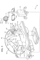
With reference to FIGS. 1 and 3A, in one embodiment, the cutting
一実施形態では、送達装置102は、切断アクセサリ130内に一体化されている。この場合、切断アクセサリ130は、材料を目標部位112に送達させる時の中心管腔を画定している。その結果、送達器具100からの切除アクセサリ130の取外し及び別体の送達装置102の取付けが不必要になる。この便利さは、迅速な処理時間を必要とする処置又は組織の切除及び材料の送達を同時に行う処置において望ましい。
In one embodiment, the
送達器具100は、目標部位112への送達器具100の移動及び/又は材料の送達を制御するためにどのような適切な機構を備えていてもよい。一実施形態では、送達器具100は、ボタン又はトリガー113を備えている。トリガー113は、図1に示されるように、送達器具100内に一体化されていてもよいし、又は送達器具100に遠隔連結されていてもよい。トリガー113は、アクチュエータ120,122,124、制御装置106、及び材料供給システム170のいずれかに通信しているとよい。トリガー113は、いくつかの異なる機能を有しているとよい。いくつかの実施形態では、トリガー113は、本明細書に記載される送達器具100の機能のいずれかを制御するための多トリガーであってもよい。
The
一例では、トリガーを押下かつ保持することによって、材料を送達し、トリガー113を解放することによって、材料の送達を停止するようになっている。代替的に、トリガー113をいったん押圧し、(次いで解放する)ことによって、材料の流れを開始させ、トリガー113を再び押圧し、(次いで解放する)ことによって、材料の流れを停止するようになっていてもよい。いずれにしても、トリガー113を押圧することによって、本明細書に記載されるような材料の送達の自動制御が可能になる。追加的に、材料の送達流量がトリガー113の押下される程度に対応するようになっていてもよい。例えば、トリガー113を完全に押下することによって、材料を最大流量で送達し、トリガー113を部分的に押下することによって、材料を(最大ではない)部分的な流量で送達するようになっていてもよい。ヒトオペレータ又はロボットオペレータが、必要に応じて、トリガー113の位置を制御するとよい。さらに、トリガー113によって、オペレータは、目標部位112に対して遠位端チップ108を位置決めするために、アクチュエータ120,122,124のいずれかを手動によって制御することが可能にする。
In one example, pressing and holding the trigger delivers the material, and releasing the
当業者であれば、送達器具100の前述の機能を制御するために、ボタン又はトリガー113以外の手段が設けられもよいことを理解されたい。例えば、一実施形態では、足ペダルが送達器具100に連結されていてもよい。オペレータは、足ペダルを押下する。足ペダルを押下した結果として、材料の送達流量が、トリガー113に関連して前述したのと同様に制御されることになる。例えば、足ペダルを押下し、かつ該ペダルを保持することによって、材料を送達し、足ペダルを解放することによって、材料の送達を停止するようになっている。代替的に、足ペダルをいったん押下し、(次いで解放する)ことによって、材料の流れを開始し、足ペダルを再び押下し、(次いで解放する)ことによって、材料の流れを停止するようになっていてもよい。追加的に、材料の送達流量は、足ペダルが押下される程度に対応するようになっていてもよい。例えば、足ペダルを完全に押下することによって、材料を最大流量で送達し、足ペダルを部分的に押下することによって、材料を(最大ではない)部分的な流量で送達するようになっていてもよい。
Those skilled in the art will appreciate that means other than the button or trigger 113 may be provided to control the aforementioned function of the
トリガー113及び/又は足ペダルは、手持ち式器具100又は以下に詳細に説明する図5に示されるロボットマニピュレータ302に利用されてもよい。
The
図3Aは、居所欠損部Fが患者の大腿骨に位置する場合の処置を示している。局所欠損部Fは、図示されるような不規則な形状を有している。居所欠損部Fを治療するために、軟骨及び/又は骨のような組織が切断アクセサリ130によって除去され、これによって、図3Bに示されるように、より清浄なかつより明確な3−D幾何学的形状が目標部位112を画定する。いったん目標部位112が画定されたなら、材料が送達装置の遠位端チップ108から目標部位112に送達される。一実施形態では、材料は、該材料の最終的な上面が硬化状態になった時点で大腿骨の関節面の元の欠損前形状と一致するように、目標部位112に送達される。また、硬化した材料の上面は、目標部位112を囲む大腿骨の未損傷組織と同一面をなすようになっている。
FIG. 3A shows the procedure when the missing part F is located on the femur of the patient. The local defect portion F has an irregular shape as shown in the figure. To treat the whereabouts defect F, tissues such as cartilage and / or bone are removed by the cutting
図4Aを参照すると、材料を目標部位112に送達する第1の方法が示されている。第1の方法は、オペレータが遠位端チップ108を仮想境界110内に移動させるステップを含んでいる。材料によって充填されるべき仮想境界110によって画定された空間の容積が、制御装置106によって計算されるか、又は目標部位112に送達されるべき材料の体積が、処置前に、例えば、術前又は術中に、外科医によって予め定められている。
With reference to FIG. 4A, a first method of delivering the material to the
オペレータは、材料が仮想境界110内に送達されている間、遠位端チップ108を仮想境界110内において自在に移動させる。過充填を防ぐために、目標部位112に送達された材料の体積が計算された体積又は予め定められた体積と等しくなった時、制御装置106は、材料を目標部位112に送達している送達装置102を停止する。
The operator is free to move the
また、遠位端チップ108の開口109から送達される材料の流量は、該流量が一定となるように、変動するように、又はその組合せとなるように、(材料供給装置174又は弁を制御することによって)、制御装置106によって制御されるとよい。流量は、オペレータが遠位端チップ108を目標部位112に対して移動させる速度にも依存する。例えば、速度が増大すると、流量が増大し、速度が減少すると、流量が減少する。
Further, the flow rate of the material delivered from the
流量は、流量が移動に対して一定となるように、制御装置106によって制御されてもよい。換言すれば、オペレータが遠位端チップ108を仮想境界110内において移動させている時、制御装置106は、遠位端チップ108の速度を測定し、速度の増減によって流量の高低を制御し、これによって、単位移動当たりの一定流量を達成するようになっている。
The flow rate may be controlled by the
また、制御装置106は、オペレータが遠位端チップ108を仮想境界110のより近くに移動させた時に(材料供給装置174又は弁を制御することによって)材料の流量を少なくするようにプログラム化されているとよく、万一遠位端チップ108が仮想境界110を超えて移動したなら、制御装置106が材料の流れを停止するようになっているとよい。ナビゲーションシステム104が患者、従って、仮想境界110の移動も追跡しているので、オペレータが遠位端チップ108を明確に仮想境界110のより近くに移動させるか、又は患者、すなわち、仮想境界110を明確に遠位端チップ108のより近くに移動させることによって、遠位端チップ108を仮想境界110のより近くに移動させるとよいことを理解されたい。
The
器具100のナビゲーションシステム104及びエンコーダは、2012年8月31日に「ハウジング、ハウジングから延在する切断アクセサリ、及びハウジングに対する切断アクセサリの位置を確立するアクチュエータを備える外科器具」と題して出願された米国特許出願第13/600,888号に記載されている方法を用いて、開口109の移動を追跡するようになっている。この文献は、参照することによって、その全体がここに含まれるものとする。開口109が仮想境界110内において移動する時、制御装置106は、仮想境界110に対する開口109の位置及び方位を決定することができる。万一、開口109を画定する送達装置102の周辺の任意の部分が仮想境界110を横切ったなら、仮想境界110が送達装置102によって破られたと判断されるとよい。代替的に、トラッカー152に対する開口109の中心点の位置が知られているので、制御装置106は、仮想境界110に対する該中心点の移動を追跡してもよい。この場合、仮想境界110は、開口109の半径を考慮し、いくらか小さく画定されているとよい。
The
制御装置106は、万一オペレータが送達器具100を遠位端チップ108が仮想境界110を超えるまで移動させようとしたなら、アクチュエータ120,122,124の1つ又は複数が1つ又は複数の自由度で遠位端チップ108を仮想境界110内にとどまるように移動させるように、該アクチュエータ120,122,124をアクチュエータ制御器140を介して制御するように、プログラム化されているとよい。
The
図4Bを参照すると、材料を目標部位112に送達する第2の方法が示されている。第2の方法は、オペレータが遠位端チップ108を仮想境界110内において移動させるステップを含んでいる。材料によって充填されるべき仮想境界110によって画定された空間の容積が、制御装置106によって計算されるか、又は目標部位112に送達されるべき材料の体積が、処置前に、例えば、術前又は術中に、外科医によって予め定められている。
With reference to FIG. 4B, a second method of delivering the material to the
いったん送達される材料の全体積が決定されたなら、一実施形態によれば、制御装置106によって、仮想境界110によって画定された空間が、複数の目標下位容積200に区分化される。送達される材料の全体積も、複数の材料下位体積に分割される。具体的には、材料下位体積の各々が、目標下位容積200の1つに割り当てられる。ある場合には、材料下位体積によって画定された材料の体積は、目標下位容積200の容積と等しくなっており、この場合、目標下位容積200は、割り当てられた材料下位体積が目標下位容積200内に位置した時、完全に充填されることになる。他の実施形態では、材料下位体積によって画定された材料の体積は、目標下位容積200の容積よりも小さくてもよく、この場合、目標下位容積200は、完全に充填されないことになる。
Once the total volume of material to be delivered has been determined, according to one embodiment, the
オペレータは、材料が目標部位112に送達されている間、遠位端チップ108を仮想境界110内において自在に移動させる。遠位端チップ108が現在位置する目標下位容積200は、現目標下位容積202と呼ばれる。目標部位112における所望の充填を促進するために、遠位端チップ108が現目標下位容積202に位置している間に送達された材料の体積が、現目標下位容積202に割り当てられた材料下位体積と等しい時、制御装置106は、材料を目標部位112に送達している送達装置102を停止する。従って、遠位端チップ108が仮想境界110内において移動する時、各目標下位容積200が所望の材料下位体積によって充填されるまで、すなわち、材料の全体積が目標部位に送達されるまで、制御装置106によって、送達装置102は、材料を送達することが可能になる。
The operator is free to move the
この実施形態では、オペレータが遠位端チップ108を種々の目標下位容積200間で移動させる時、制御装置106は、各目標下位容積200に送達された材料の現在までの累計を記憶し、これによって、オペレータは、目標下位容積200のいずれかが割り当てられた所望の材料下位体積を完全に受け入れる前に、目標下位容積200間で移動することができる。この現在までの累計は、材料供給装置174が材料を目標下位容積200の各々を供給する流量及び材料が各流量で目標下位容積200に送達される時間に基づいている(容積=流量×時間)。
In this embodiment, when the operator moves the
この実施形態では、制御装置106は、遠位端チップ108が仮想境界110のより近くに移動すると、(材料供給装置174又は弁を制御することによって)、材料の流量を遅くするようにプログラム化され、万一遠位端チップ108が仮想境界110を超えて移動したなら、制御装置106が材料の流れを停止するようになっているとよい。
In this embodiment, the
代替的に、制御装置106は、万一オペレータが送達器具100を遠位端チップ108が仮想境界110を超えるまで移動させようとしたなら、アクチュエータ120,122,124の1つ又は複数が1つ又は複数の自由度で遠位端チップ108を仮想境界110内にとどまるように移動させるように、該アクチュエータ120,122,124をアクチュエータ制御器140を介して制御するように、プログラム化されていてもよい。
Alternatively, the
図4Cを参照すると、材料を目標部位112に送達する第3の方法が示されている。この第3の方法では、制御装置106は、遠位端チップ108が材料を送達する経路210を仮想境界110内に決定するようになっている。この経路は、カメラ座標系の一連の座標によって画定されるとよい。オペレータは、遠位端チップ108を仮想境界110内の大まかな位置に配置する。
With reference to FIG. 4C, a third method of delivering the material to the
いったん遠位端チップ108が大まかに配置されたなら、制御装置106が、アクチュエータ制御器140を介してアクチュエータ120,122,124の1つ又は複数を作動させ、オペレータが手動によって大まかな位置を維持している間に、遠位端チップ108を経路210に沿って自動的に移動させる。制御装置106は、遠位端チップ108が経路210を追従する時に材料が目標部位112に送達される流量を制御することになる。
Once the
流量は、例えば、経路210に沿って一定となるように制御されてもよいし、又は経路210に沿って変動するように制御されてもよい。代替的に、経路210の種々のセグメントが、種々の所定の流量に割り当てられてもよい。この場合、制御装置106は、遠位端チップ108が位置するセグメントに基づき材料を種々の所定の流量で送るように、材料供給装置174を制御することになる。
The flow rate may be controlled to be constant along the
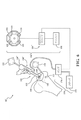
図5を参照すると、送達システムの代替的実施形態が、総称的に10’で示されている。この実施形態では、装置器具100’は、ロボットマニピュレータ302に取り付けられている。送達装置10’は、ここでも、送達器具100’に取外し可能に取り付けられた送達装置102、複数のアクチュエータ120’,122’,124’(ジョイントモータ)、ナビゲーションシステム104、制御装置106、及び材料供給システム170を備えている。
With reference to FIG. 5, alternative embodiments of the delivery system are collectively indicated by 10'. In this embodiment, the device instrument 100'is attached to the
ロボットマニピュレータ302は、アームを形成する複数のリンケージ306と、目標部位112に対して送達装置102を移動させるための(部番が付されていない)複数の能動的ジョイントと、を備えている。ロボットマニピュレータ302は、送達装置102に動作可能に連結されている。オペレータによって送達器具100’に加えられた力及び/又はトルクを検知するために、力/トルクセンサのようなセンサ311が、送達器具100’とロボットマニピュレータ302のアームとの間に連結されているとよい。
The
ロボットマニピュレータ302は、手動モード及び半自律モードを含む多重モードで操作されるとよい。多重モードで操作可能なロボットマニピュレータ302の例は、「外科器具を多重モードで制御することができる外科マニピュレータ」と題して出願された米国特許出願第13/958,070号に記載されている。この文献の開示内容は、参照することによって、ここに含まれるものとする。ここに記載される外科器具を用いる生体構造の処置に関する米国特許出願第13/958,070号に記載されている手動及び半自律制御技術は、いずれも、本明細書に記載される送達器具100を用いる生体構造への材料の投与に完全に適用可能である。
The
手動モードでは、オペレータは、材料を目標部位112に送達するために、送達器具100’の把持部分160’を把持する。センサ311が把持部分160’に加えられた力/トルクを検知し、制御装置106が検知された力/トルクを表す信号を受信する。制御装置106は、オペレータの手動によって加えられた運動に応じて、送達器具100’及び/又は遠位端チップ108の移動をロボットマニピュレータ302を介して制御するように構成されている。すなわち、アクチェータ120’、122’、124’は、オペレータが手動によって把持部分160’に加えた力/トルクに基づき、送達器具100’及び/又は遠位端チップ108をセンサ311によって検知された所望の位置に移動させるように、能動的に駆動される。ナビゲーションシステム104は、遠位端チップ108を仮想境界110に対して所望の関係に保つために、送達装置102を追跡する。手動モードでは、オペレータは、図4A、図4Bおよび図4Cに関して前述した送達方法を用いて材料を目標部位112に送達することができる。
In manual mode, the operator grips the grip portion 160'of the delivery device 100'to deliver the material to the
前述したように、ロボットマニピュレータ302、さらに具体的には、ロボットマニピュレータ302に取り付けられた送達器具100’は、ボタン又はトリガー113を備えていてもよい。手動モードでは、トリガー113を押圧することによって、どのような適切な制御、例えば、前述したような制御による材料の投与も手動によって制御することが可能である。
As described above, the
半自律モードでは、ロボットマニピュレータ302は、所定のパラメータに基づき材料を目標部位112に自律的に送達する。半自律モードでは、制御装置106は、送達器具100’及び/又は遠位端チップ108の移動をロボットマニピュレータ302を介して自律的に制御するように構成されている。所定のパラメータは、例えば、予めプログラム化された送達経路又は送達パターンである。一例では、ロボットマニピュレータ302は、本質的にオペレータからの方向入力を必要とすることなく、半自律モードで操作するようになっている。
In the semi-autonomous mode, the
ロボットマニピュレータ302が送達装置102を自律的に移動させるために、オペレータは、ロボットに関連付けられた制御ボタン又は制御スイッチを連続的に押下することによって、指令を発動するとよい。オペレータによる指令が取り消されると、ロボットマニピュレータ302による送達器具100’の前進が、少なくとも一時的に停止する。ロボットマニピュレータ302の自律的移動を開始する制御ボタン又は制御スイッチは、トリガー113であってもよいし、又は前述の足ペダルであってもよい。
In order for the
追加的又は代替的に、ロボットマニピュレータ302に取り付けられた送達器具100’がボタン又はトリガー113を備えている場合、半自律モードにおいて、トリガー113を押圧することによって、前述したような任意の適切な制御に従って、材料の自律投与を手動制御することが可能になる。例えば、このモードにおいて、トリガーを一回押圧することによって、材料がロボットマニピュレータ302を介して自律的に投与されるとよい。その後、トリガー113を再び押圧することによって、ロボットマニピュレータ302を介する材料の自律的投与が停止されるとよい。代替的に、このモードにおいて、トリガー113を押し続けることによって、材料をロボットマニピュレータ302を介して自律的に投与するようになっていてもよい。
Additional or alternative, if the delivery device 100'attached to the
いくつかの実施形態では、オペレータが望ましくない移動を試みていると制御装置106が判断した時、送達器具100’は、オペレータに触覚フィードバックを与えるようになっている。望ましくない移動の例として、送達器具100’又は遠位端チップ108が仮想境界110を超えようとする移動が挙げられる。触覚フィードバックは、一般的に、オペレータの触覚に注意を与える任意の形式のフィードバックを含んでいる。触覚フィードバックの例として、力フィードバック、振動フィードバック、物理的反発、等の任意の1つ又は複数が挙げられる。遠位端チップ108を所望の位置に保つようにオペレータに注意を喚起するために、例えば、送達器具100’が把持部分160’に振動エネルギーを生成してもよいし、又は複数のアクチュエータ120’、122’、124’がオペレータによって検知された力を把持部分160’を通してオペレータに再び伝達するようになっていてもよい。場合によっては、遠位端チップ108が仮想境界110の制限を越えようとした時、遠位端チップ108は、仮想境界110から離れる方に移動するように作動されてもよい。この反発移動は、触覚によって、仮想境界110の制限をオペレータに警告し、及び/又はこのような反発が生じたことをオペレータに警告することによってなされるとよい。
In some embodiments, the delivery device 100'provides tactile feedback to the operator when the
図6を参照すると、送達システムの第2の代替的実施形態が総称的に10’’で示されている。この実施形態では、送達システム10’’は、送達器具100’’、送達装置102、ナビゲーションシステム104’’、制御装置106’’、及び材料を送達装置102に送達するための材料供給システム170を備えている。先の実施形態と同様、ナビゲーションシステム104は、送達装置102の遠位端チップ108を仮想境界110に対して所望の関係に保つために、送達装置102を追跡するようになっている。
With reference to FIG. 6, a second alternative embodiment of the delivery system is generically indicated by 10 ″. In this embodiment, the
この実施形態では、オペレータは、送達装置102の移動を生じさせるどのようなアクチュエータも用いることなく、送達器具100’’を手で支持し、直接移動させるヒトオペレータである。送達器具100’’は、オペレータによって把持される把持部分160’’を備えている。把持部分160’’は、圧入、接着剤、バイオネット接続、ネジ接続、等によって送達装置102(及びその開口)に固定されている。送達装置102は、送達装置102が送達器具100’’の一部であり、把持部分が送達器具100’’の他の部分であるように、送達器具100’’と一体化されていてもよい。
In this embodiment, the operator is a human operator who manually supports and directly moves the
この実施形態では、ナビゲーションシステム104’’は、制御装置106’’がナビゲーションコンピュータ156及び制御装置106を一体化させ、それらの機能を組合せていることを除けば、他の実施形態の特徴と同じ特徴を有している。この実施形態における制御装置106’’は、図4A、図4Bおよび図4Cに関して前述した送達方法を用いて、材料供給システム170を制御するようになっている。流量も、前述の例に従って制御されるとよい。
In this embodiment, the
いくつかの実施形態では、送達装置102から送達される材料を追跡することが望ましい。例えば、材料は、最終的に移植片を形成するので、処置中、外科医は、この移植片の構築を視覚化することを望むことになる。従って、送達される材料は、外科医に進展を示すために、ディスプレイ上に連続的に表示されるとよい。これは、目標部位、開口109、及び材料の流量を追跡し、対応する出力信号をディスプレイ上に生成し、送達中の開口109の位置及び方位を考慮した材料の表象及び送達される材料の量を示すことによって行われるとよい。送達される材料が、色分けされてもよい。具体的には、最後に送達される材料が1つの色としてディスプレイ上に表示され、その前に投与された先の材料が異なる色によってディスプレイ上に表示されるとよい。目標部位に対する移植片の構築を示すために、骨のような目標部位が表示され、これによって、外科医は、患者の実生体構造に対する移植片の構築を視覚化することができる。
In some embodiments, it is desirable to track the material delivered from the
以上の説明において、いくつかの実施形態について検討してきた。しかし、本明細書において検討した実施形態は、包括的であることを意図するものではなく、また本発明を特定の形態に制限することに意図するものでもない。用いられた専門用語は、制限的というよりも記述的であることが意図されている。上記の示唆に照らして、多くの修正及び変更が可能であり、本発明は、具体的に記載されたものと異なる方法によって実施されてもよい。
In the above description, some embodiments have been examined. However, the embodiments discussed herein are not intended to be comprehensive, nor are they intended to limit the invention to any particular embodiment. The terminology used is intended to be descriptive rather than restrictive. Many modifications and modifications are possible in light of the above suggestions, and the present invention may be practiced in a manner different from that specifically described.
Claims (8)
オペレータによって把持可能である把持部分(160)と、
該把持部分(160)に連結される手持ち式送達装置(102)であって、開口(109)を有し、前記材料を前記開口(109)を通して前記目標部位(112)に送達するように構成された手持ち式送達装置(102)と、
前記送達装置(102)に動作可能に連結された少なくとも1つのアクチュエータ(120、122、124)であって、把持部分に対して少なくとも2自由度で前記開口(109)を移動するように構成される少なくとも1つのアクチュエータ(120、122、124)と、を備える手持ち式送達器具(100)と、
前記送達装置(102)及び前記目標部位(112)を追跡し、位置信号を生成するように構成されたナビゲーションシステム(104)と、
前記送達装置(102)及び前記ナビゲーションシステム(104)と通信する制御装置(106)であって、前記目標部位(112)と関連付けられた仮想境界(110)を画定し、前記ナビゲーションシステム(104)からの前記位置信号に基づき、少なくとも2自由度で前記少なくとも1つのアクチュエータ(120、122、124)を制御することによって、前記仮想境界(110)に対する前記開口(109)の移動を制御するように構成されている、制御装置(106)と、
を備えている、送達システム(10)。 The delivery system (10) for delivering the material to the target site (112) is a handheld delivery device (100).
A gripping portion (160) that can be gripped by an operator,
A handheld delivery device (102) coupled to the grip portion (160) that has an opening (109) and is configured to deliver the material through the opening (109) to the target site (112). Handheld delivery device (102)
At least one actuator (120, 122, 124) operably coupled to the delivery device (102), configured to move the opening (109) with at least two degrees of freedom with respect to the grip portion. A handheld delivery device (100) comprising at least one actuator (120, 122, 124).
A navigation system (104) configured to track the delivery device (102) and the target site (112) and generate a position signal.
A control device (106) that communicates with the delivery device (102) and the navigation system (104), defining a virtual boundary (110) associated with the target site (112) and defining the navigation system (104). Control the movement of the opening (109) with respect to the virtual boundary (110) by controlling the at least one actuator (120, 122, 124) with at least two degrees of freedom based on the position signal from. The controller (106), which is configured,
The delivery system (10).
Applications Claiming Priority (3)
| Application Number | Priority Date | Filing Date | Title |
|---|---|---|---|
| US201562183374P | 2015-06-23 | 2015-06-23 | |
| US62/183,374 | 2015-06-23 | ||
| PCT/US2016/038941 WO2016210081A1 (en) | 2015-06-23 | 2016-06-23 | Delivery system and method for delivering material to a target site |
Publications (3)
| Publication Number | Publication Date |
|---|---|
| JP2018527043A JP2018527043A (en) | 2018-09-20 |
| JP2018527043A5 JP2018527043A5 (en) | 2019-07-25 |
| JP6929233B2 true JP6929233B2 (en) | 2021-09-01 |
Family
ID=56557882
Family Applications (1)
| Application Number | Title | Priority Date | Filing Date |
|---|---|---|---|
| JP2017566755A Active JP6929233B2 (en) | 2015-06-23 | 2016-06-23 | Delivery system and method for delivering material to the target site |
Country Status (6)
| Country | Link |
|---|---|
| US (3) | US10492875B2 (en) |
| EP (2) | EP3313309B1 (en) |
| JP (1) | JP6929233B2 (en) |
| AU (1) | AU2016282759A1 (en) |
| CA (1) | CA2990631A1 (en) |
| WO (1) | WO2016210081A1 (en) |
Families Citing this family (23)
| Publication number | Priority date | Publication date | Assignee | Title |
|---|---|---|---|---|
| CA2847182C (en) | 2011-09-02 | 2020-02-11 | Stryker Corporation | Surgical instrument including a cutting accessory extending from a housing and actuators that establish the position of the cutting accessory relative to the housing |
| WO2016210081A1 (en) | 2015-06-23 | 2016-12-29 | Stryker Corporation | Delivery system and method for delivering material to a target site |
| CN109952070B (en) | 2016-10-05 | 2022-02-01 | 纽文思公司 | Surgical navigation system and related methods |
| US11864795B2 (en) * | 2017-04-02 | 2024-01-09 | Mazor Robotics Ltd. | Three dimensional robotic bioprinter |
| IT201700039905A1 (en) * | 2017-04-11 | 2018-10-11 | Marcello Marchesi | SURGICAL SURFACE SYSTEM |
| US10806529B2 (en) * | 2017-07-20 | 2020-10-20 | Mako Surgical Corp. | System and method for robotically assisting a surgical procedure |
| CN116531584A (en) * | 2017-10-23 | 2023-08-04 | 史赛克公司 | Autonomous waste collection assembly and medical waste collection system and method |
| US11272985B2 (en) | 2017-11-14 | 2022-03-15 | Stryker Corporation | Patient-specific preoperative planning simulation techniques |
| JP7314175B2 (en) | 2018-05-18 | 2023-07-25 | オーリス ヘルス インコーポレイテッド | Controller for robotic remote control system |
| US11478307B2 (en) | 2018-12-18 | 2022-10-25 | Mako Surgical Corp. | Systems and methods for fiber optic tracking |
| US11439411B2 (en) * | 2019-05-24 | 2022-09-13 | Think Surgical, Inc. | System and method to improve surgical cutting in the presence of surgical debris |
| US11744659B2 (en) | 2019-07-19 | 2023-09-05 | Corindus, Inc. | Load sensing of elongated medical device in robotic actuation |
| US11612440B2 (en) | 2019-09-05 | 2023-03-28 | Nuvasive, Inc. | Surgical instrument tracking devices and related methods |
| US11964074B2 (en) | 2019-12-17 | 2024-04-23 | Warsaw Orthopedic, Inc. | Additive-manufactured non-woven fibrous implants, systems, and related methods |
| US20210177603A1 (en) * | 2019-12-17 | 2021-06-17 | Warsaw Orthopedic, Inc. | In-situ additive manufactured motion-sparing implants |
| US11903846B2 (en) | 2019-12-17 | 2024-02-20 | Warsaw Orthopedic, Inc. | In-situ additive expandable implants |
| US11903841B2 (en) * | 2020-06-22 | 2024-02-20 | Warsaw Orthopedic, Inc. | In-situ additive channeled implants |
| US11523916B2 (en) * | 2019-12-17 | 2022-12-13 | Warsaw Orthopedic, Inc. | In-situ additive implants |
| US11523909B2 (en) | 2019-12-17 | 2022-12-13 | Warsaw Orthopedic, Inc. | In-situ additive implants |
| WO2022076686A1 (en) | 2020-10-07 | 2022-04-14 | Canary Medical Switzerland Ag | Providing medical devices with sensing functionality |
| CN112223299B (en) * | 2020-12-11 | 2021-03-12 | 南京佗道医疗科技有限公司 | System precision verification device and method |
| US11628069B2 (en) * | 2020-12-29 | 2023-04-18 | King Abdulaziz University | 3D printing of polymeric bioceramics for the treatment of bone defects |
| CN113694297B (en) * | 2021-09-27 | 2023-07-25 | 江苏大学附属医院 | Hospital intelligent mechanical arm liquid exchange system |
Family Cites Families (66)
| Publication number | Priority date | Publication date | Assignee | Title |
|---|---|---|---|---|
| ATE123957T1 (en) * | 1990-12-07 | 1995-07-15 | Ruesch Willy Ag | MEDICAL INSTRUMENT WITH DIRECTORABLE TIP. |
| US5865744A (en) * | 1996-09-16 | 1999-02-02 | Lemelson; Jerome H. | Method and system for delivering therapeutic agents |
| US5845646A (en) * | 1996-11-05 | 1998-12-08 | Lemelson; Jerome | System and method for treating select tissue in a living being |
| US6293282B1 (en) * | 1996-11-05 | 2001-09-25 | Jerome Lemelson | System and method for treating select tissue in living being |
| US6058323A (en) * | 1996-11-05 | 2000-05-02 | Lemelson; Jerome | System and method for treating select tissue in a living being |
| US6286514B1 (en) * | 1996-11-05 | 2001-09-11 | Jerome Lemelson | System and method for treating select tissue in a living being |
| US5919135A (en) * | 1997-02-28 | 1999-07-06 | Lemelson; Jerome | System and method for treating cellular disorders in a living being |
| US6398726B1 (en) * | 1998-11-20 | 2002-06-04 | Intuitive Surgical, Inc. | Stabilizer for robotic beating-heart surgery |
| US6659939B2 (en) * | 1998-11-20 | 2003-12-09 | Intuitive Surgical, Inc. | Cooperative minimally invasive telesurgical system |
| US6197115B1 (en) | 1999-03-30 | 2001-03-06 | Abb Flexible Automation Inc. | Robot based sealant dispenser |
| US7635390B1 (en) | 2000-01-14 | 2009-12-22 | Marctec, Llc | Joint replacement component having a modular articulating surface |
| AU2002248360A1 (en) | 2001-01-16 | 2002-08-19 | Microdexterity Systems, Inc. | Surgical manipulator |
| US7892243B2 (en) | 2001-01-16 | 2011-02-22 | Microdexterity Systems, Inc. | Surgical manipulator |
| US6861982B2 (en) | 2001-08-16 | 2005-03-01 | Itt Manufacturing Enterprises, Inc. | System for determining position of an emitter |
| DE50107066D1 (en) * | 2001-11-30 | 2005-09-15 | Brainlab Ag | Device for planning an infusion |
| US20030175410A1 (en) | 2002-03-18 | 2003-09-18 | Campbell Phil G. | Method and apparatus for preparing biomimetic scaffold |
| US6757582B2 (en) | 2002-05-03 | 2004-06-29 | Carnegie Mellon University | Methods and systems to control a shaping tool |
| US7697972B2 (en) * | 2002-11-19 | 2010-04-13 | Medtronic Navigation, Inc. | Navigation system for cardiac therapies |
| US7542791B2 (en) * | 2003-01-30 | 2009-06-02 | Medtronic Navigation, Inc. | Method and apparatus for preplanning a surgical procedure |
| US7960935B2 (en) | 2003-07-08 | 2011-06-14 | The Board Of Regents Of The University Of Nebraska | Robotic devices with agent delivery components and related methods |
| US20050261591A1 (en) * | 2003-07-21 | 2005-11-24 | The Johns Hopkins University | Image guided interventions with interstitial or transmission ultrasound |
| US7974681B2 (en) * | 2004-03-05 | 2011-07-05 | Hansen Medical, Inc. | Robotic catheter system |
| US8052636B2 (en) * | 2004-03-05 | 2011-11-08 | Hansen Medical, Inc. | Robotic catheter system and methods |
| US8005537B2 (en) * | 2004-07-19 | 2011-08-23 | Hansen Medical, Inc. | Robotically controlled intravascular tissue injection system |
| US8182491B2 (en) | 2004-08-06 | 2012-05-22 | Depuy Spine, Inc. | Rigidly guided implant placement |
| US8989349B2 (en) | 2004-09-30 | 2015-03-24 | Accuray, Inc. | Dynamic tracking of moving targets |
| US9901413B2 (en) * | 2004-10-15 | 2018-02-27 | Brainlab Ag | Targeted infusion of agents for treatment of ALS |
| US20090209852A1 (en) | 2005-03-02 | 2009-08-20 | Calypso Medical Technologies, Inc. | Systems and Methods for Treating a Patient Using Guided Radiation Therapy or Surgery |
| WO2006119495A2 (en) * | 2005-05-03 | 2006-11-09 | Hansen Medical, Inc. | Robotic catheter system |
| WO2007005976A1 (en) * | 2005-07-01 | 2007-01-11 | Hansen Medical, Inc. | Robotic catheter system |
| US7962192B2 (en) * | 2005-09-30 | 2011-06-14 | Restoration Robotics, Inc. | Systems and methods for aligning a tool with a desired location or object |
| US20070078466A1 (en) * | 2005-09-30 | 2007-04-05 | Restoration Robotics, Inc. | Methods for harvesting follicular units using an automated system |
| WO2007056506A2 (en) | 2005-11-09 | 2007-05-18 | Fell Barry M | System and method for shaping an anatomical component |
| US8190238B2 (en) * | 2005-12-09 | 2012-05-29 | Hansen Medical, Inc. | Robotic catheter system and methods |
| US20070167745A1 (en) * | 2005-12-29 | 2007-07-19 | Cook Incorporated | Methods for delivering medical devices to a target implant site within a body vessel |
| US8060181B2 (en) * | 2006-04-07 | 2011-11-15 | Brainlab Ag | Risk assessment for planned trajectories |
| CA2648434C (en) * | 2006-04-13 | 2011-08-09 | Wilson-Cook Medical Inc. | Apparatus and methods for endoscopic resection of tissue |
| US8409172B2 (en) * | 2006-08-03 | 2013-04-02 | Hansen Medical, Inc. | Systems and methods for performing minimally invasive procedures |
| US8160676B2 (en) * | 2006-09-08 | 2012-04-17 | Medtronic, Inc. | Method for planning a surgical procedure |
| US8150497B2 (en) * | 2006-09-08 | 2012-04-03 | Medtronic, Inc. | System for navigating a planned procedure within a body |
| US8660635B2 (en) * | 2006-09-29 | 2014-02-25 | Medtronic, Inc. | Method and apparatus for optimizing a computer assisted surgical procedure |
| US7922688B2 (en) * | 2007-01-08 | 2011-04-12 | Restoration Robotics, Inc. | Automated delivery of a therapeutic or cosmetic substance to cutaneous, subcutaneous and intramuscular tissue regions |
| US8391957B2 (en) * | 2007-03-26 | 2013-03-05 | Hansen Medical, Inc. | Robotic catheter systems and methods |
| US20080294107A1 (en) * | 2007-05-22 | 2008-11-27 | Convergent Medical Solutions, Inc. | Multiple robotic injections of prenatal medications based on scanned image |
| US8409234B2 (en) * | 2007-05-25 | 2013-04-02 | Hansen Medical, Inc. | Rotational apparatus system and method for a robotic instrument system |
| KR101107440B1 (en) * | 2007-06-26 | 2012-01-19 | 레스토레이션 로보틱스, 인코포레이티드 | Follicular unit harvesting tools including devices and their use for severing connective tissue |
| US8740840B2 (en) * | 2008-01-16 | 2014-06-03 | Catheter Robotics Inc. | Remotely controlled catheter insertion system |
| US8801725B2 (en) | 2008-03-10 | 2014-08-12 | Zimmer Orthobiologics, Inc. | Instruments and methods used when repairing a defect on a tissue surface |
| US8343096B2 (en) * | 2008-03-27 | 2013-01-01 | St. Jude Medical, Atrial Fibrillation Division, Inc. | Robotic catheter system |
| US8335552B2 (en) * | 2009-03-20 | 2012-12-18 | Medtronic, Inc. | Method and apparatus for instrument placement |
| US20110015648A1 (en) * | 2009-07-16 | 2011-01-20 | Hansen Medical, Inc. | Endoscopic robotic catheter system |
| US20110015484A1 (en) * | 2009-07-16 | 2011-01-20 | Alvarez Jeffrey B | Endoscopic robotic catheter system |
| KR101609281B1 (en) | 2009-10-01 | 2016-04-05 | 마코 서지컬 코포레이션 | Tool, kit-of-parts for multi-functional tool, and robotic system for same |
| US8652148B2 (en) | 2010-02-25 | 2014-02-18 | Zimmer, Inc. | Tracked cartilage repair system |
| JP5757961B2 (en) | 2010-03-04 | 2015-08-05 | アンスティチュ ナショナル ドゥ ラ サンテ エ ドゥ ラ ルシェルシュ メディカル | Bioprinting station, assembly including the bioprinting station, and bioprinting method |
| US8651046B1 (en) | 2010-07-23 | 2014-02-18 | The Boeing Company | Robotic sealant and end effector |
| US9119655B2 (en) | 2012-08-03 | 2015-09-01 | Stryker Corporation | Surgical manipulator capable of controlling a surgical instrument in multiple modes |
| EP2720636B8 (en) | 2011-06-17 | 2020-04-08 | Koninklijke Philips N.V. | System for guided injection during endoscopic surgery |
| US9498231B2 (en) | 2011-06-27 | 2016-11-22 | Board Of Regents Of The University Of Nebraska | On-board tool tracking system and methods of computer assisted surgery |
| CA2847182C (en) * | 2011-09-02 | 2020-02-11 | Stryker Corporation | Surgical instrument including a cutting accessory extending from a housing and actuators that establish the position of the cutting accessory relative to the housing |
| MX2015002400A (en) | 2012-08-24 | 2015-11-09 | Univ Houston | Robotic device and systems for image-guided and robot-assisted surgery. |
| US9192445B2 (en) | 2012-12-13 | 2015-11-24 | Mako Surgical Corp. | Registration and navigation using a three-dimensional tracking sensor |
| US11369465B2 (en) | 2013-01-14 | 2022-06-28 | Scripps Health | Tissue array printing |
| AU2014207502B2 (en) | 2013-01-16 | 2018-10-18 | Stryker Corporation | Navigation systems and methods for indicating line-of-sight errors |
| US20140276936A1 (en) * | 2013-03-15 | 2014-09-18 | Hansen Medical, Inc. | Active drive mechanism for simultaneous rotation and translation |
| WO2016210081A1 (en) | 2015-06-23 | 2016-12-29 | Stryker Corporation | Delivery system and method for delivering material to a target site |
-
2016
- 2016-06-23 WO PCT/US2016/038941 patent/WO2016210081A1/en unknown
- 2016-06-23 EP EP16745553.4A patent/EP3313309B1/en active Active
- 2016-06-23 AU AU2016282759A patent/AU2016282759A1/en not_active Abandoned
- 2016-06-23 US US15/190,581 patent/US10492875B2/en active Active
- 2016-06-23 JP JP2017566755A patent/JP6929233B2/en active Active
- 2016-06-23 CA CA2990631A patent/CA2990631A1/en not_active Abandoned
- 2016-06-23 EP EP21183884.2A patent/EP3912577A1/en active Pending
-
2019
- 2019-09-19 US US16/575,879 patent/US11406461B2/en active Active
-
2022
- 2022-07-01 US US17/855,857 patent/US20220331030A1/en active Pending
Also Published As
| Publication number | Publication date |
|---|---|
| US11406461B2 (en) | 2022-08-09 |
| US20220331030A1 (en) | 2022-10-20 |
| WO2016210081A1 (en) | 2016-12-29 |
| EP3313309A1 (en) | 2018-05-02 |
| EP3313309B1 (en) | 2021-07-21 |
| AU2016282759A1 (en) | 2018-02-01 |
| EP3912577A1 (en) | 2021-11-24 |
| US20200008893A1 (en) | 2020-01-09 |
| CA2990631A1 (en) | 2016-12-29 |
| US20160374770A1 (en) | 2016-12-29 |
| US10492875B2 (en) | 2019-12-03 |
| JP2018527043A (en) | 2018-09-20 |
Similar Documents
| Publication | Publication Date | Title |
|---|---|---|
| JP6929233B2 (en) | Delivery system and method for delivering material to the target site | |
| US20210307849A1 (en) | Robotic Spine Surgery System And Methods | |
| US11033341B2 (en) | Robotic spine surgery system and methods | |
| CN107427330B (en) | System and method for controlling a surgical tool during autonomous movement of the surgical tool | |
| US11903662B2 (en) | System and method for robotically assisting a surgical procedure | |
| US20220273396A1 (en) | Robotic Hand-Held Surgical Instrument Systems And Methods | |
| US11337766B2 (en) | Robotic surgical system and methods utilizing a cutting bur for bone penetration and cannulation | |
| US11944396B2 (en) | Systems and methods for controlling robotic movement of a tool based on a virtual boundary | |
| US20210128248A1 (en) | Robotic medical apparatus, system, and method | |
| US20220361972A1 (en) | Surgical robotic system | |
| KR20220070226A (en) | Surgical system and method for guiding robotic manipulators | |
| JP2023519879A (en) | Robotic spine surgery system and method with haptic interface | |
| US20110208196A1 (en) | Device and method for working material | |
| US20240108358A1 (en) | Robotic Hand-Held Surgical Instrument Systems And Methods | |
| CN113038899A (en) | Robotic spinal surgical system and method |
Legal Events
| Date | Code | Title | Description |
|---|---|---|---|
| A521 | Request for written amendment filed |
Free format text: JAPANESE INTERMEDIATE CODE: A523 Effective date: 20190618 |
|
| A621 | Written request for application examination |
Free format text: JAPANESE INTERMEDIATE CODE: A621 Effective date: 20190618 |
|
| A977 | Report on retrieval |
Free format text: JAPANESE INTERMEDIATE CODE: A971007 Effective date: 20200604 |
|
| A131 | Notification of reasons for refusal |
Free format text: JAPANESE INTERMEDIATE CODE: A131 Effective date: 20200619 |
|
| A521 | Request for written amendment filed |
Free format text: JAPANESE INTERMEDIATE CODE: A523 Effective date: 20200916 |
|
| A131 | Notification of reasons for refusal |
Free format text: JAPANESE INTERMEDIATE CODE: A131 Effective date: 20210205 |
|
| A601 | Written request for extension of time |
Free format text: JAPANESE INTERMEDIATE CODE: A601 Effective date: 20210506 |
|
| A521 | Request for written amendment filed |
Free format text: JAPANESE INTERMEDIATE CODE: A523 Effective date: 20210705 |
|
| TRDD | Decision of grant or rejection written | ||
| A01 | Written decision to grant a patent or to grant a registration (utility model) |
Free format text: JAPANESE INTERMEDIATE CODE: A01 Effective date: 20210716 |
|
| A61 | First payment of annual fees (during grant procedure) |
Free format text: JAPANESE INTERMEDIATE CODE: A61 Effective date: 20210810 |
|
| R150 | Certificate of patent or registration of utility model |
Ref document number: 6929233 Country of ref document: JP Free format text: JAPANESE INTERMEDIATE CODE: R150 |