JP6929028B2 - Devices, methods and programs that detect people using range-finding sensors - Google Patents
Devices, methods and programs that detect people using range-finding sensors Download PDFInfo
- Publication number
- JP6929028B2 JP6929028B2 JP2016150367A JP2016150367A JP6929028B2 JP 6929028 B2 JP6929028 B2 JP 6929028B2 JP 2016150367 A JP2016150367 A JP 2016150367A JP 2016150367 A JP2016150367 A JP 2016150367A JP 6929028 B2 JP6929028 B2 JP 6929028B2
- Authority
- JP
- Japan
- Prior art keywords
- distance
- information processing
- background data
- power state
- determination
- Prior art date
- Legal status (The legal status is an assumption and is not a legal conclusion. Google has not performed a legal analysis and makes no representation as to the accuracy of the status listed.)
- Active
Links
Images


Classifications
-
- G—PHYSICS
- G01—MEASURING; TESTING
- G01S—RADIO DIRECTION-FINDING; RADIO NAVIGATION; DETERMINING DISTANCE OR VELOCITY BY USE OF RADIO WAVES; LOCATING OR PRESENCE-DETECTING BY USE OF THE REFLECTION OR RERADIATION OF RADIO WAVES; ANALOGOUS ARRANGEMENTS USING OTHER WAVES
- G01S15/00—Systems using the reflection or reradiation of acoustic waves, e.g. sonar systems
- G01S15/02—Systems using the reflection or reradiation of acoustic waves, e.g. sonar systems using reflection of acoustic waves
- G01S15/04—Systems determining presence of a target
-
- G—PHYSICS
- G01—MEASURING; TESTING
- G01S—RADIO DIRECTION-FINDING; RADIO NAVIGATION; DETERMINING DISTANCE OR VELOCITY BY USE OF RADIO WAVES; LOCATING OR PRESENCE-DETECTING BY USE OF THE REFLECTION OR RERADIATION OF RADIO WAVES; ANALOGOUS ARRANGEMENTS USING OTHER WAVES
- G01S15/00—Systems using the reflection or reradiation of acoustic waves, e.g. sonar systems
- G01S15/02—Systems using the reflection or reradiation of acoustic waves, e.g. sonar systems using reflection of acoustic waves
- G01S15/06—Systems determining the position data of a target
- G01S15/08—Systems for measuring distance only
-
- G—PHYSICS
- G01—MEASURING; TESTING
- G01S—RADIO DIRECTION-FINDING; RADIO NAVIGATION; DETERMINING DISTANCE OR VELOCITY BY USE OF RADIO WAVES; LOCATING OR PRESENCE-DETECTING BY USE OF THE REFLECTION OR RERADIATION OF RADIO WAVES; ANALOGOUS ARRANGEMENTS USING OTHER WAVES
- G01S15/00—Systems using the reflection or reradiation of acoustic waves, e.g. sonar systems
- G01S15/88—Sonar systems specially adapted for specific applications
-
- H—ELECTRICITY
- H04—ELECTRIC COMMUNICATION TECHNIQUE
- H04N—PICTORIAL COMMUNICATION, e.g. TELEVISION
- H04N1/00—Scanning, transmission or reproduction of documents or the like, e.g. facsimile transmission; Details thereof
- H04N1/0035—User-machine interface; Control console
- H04N1/00352—Input means
- H04N1/00381—Input by recognition or interpretation of visible user gestures
-
- H—ELECTRICITY
- H04—ELECTRIC COMMUNICATION TECHNIQUE
- H04N—PICTORIAL COMMUNICATION, e.g. TELEVISION
- H04N1/00—Scanning, transmission or reproduction of documents or the like, e.g. facsimile transmission; Details thereof
- H04N1/00885—Power supply means, e.g. arrangements for the control of power supply to the apparatus or components thereof
- H04N1/00888—Control thereof
- H04N1/00896—Control thereof using a low-power mode, e.g. standby
-
- H—ELECTRICITY
- H04—ELECTRIC COMMUNICATION TECHNIQUE
- H04N—PICTORIAL COMMUNICATION, e.g. TELEVISION
- H04N1/00—Scanning, transmission or reproduction of documents or the like, e.g. facsimile transmission; Details thereof
- H04N1/00912—Arrangements for controlling a still picture apparatus or components thereof not otherwise provided for
-
- H—ELECTRICITY
- H04—ELECTRIC COMMUNICATION TECHNIQUE
- H04N—PICTORIAL COMMUNICATION, e.g. TELEVISION
- H04N2201/00—Indexing scheme relating to scanning, transmission or reproduction of documents or the like, and to details thereof
- H04N2201/0077—Types of the still picture apparatus
- H04N2201/0094—Multifunctional device, i.e. a device capable of all of reading, reproducing, copying, facsimile transception, file transception
Landscapes
- Engineering & Computer Science (AREA)
- Radar, Positioning & Navigation (AREA)
- Remote Sensing (AREA)
- Physics & Mathematics (AREA)
- Signal Processing (AREA)
- Computer Networks & Wireless Communication (AREA)
- General Physics & Mathematics (AREA)
- Multimedia (AREA)
- Acoustics & Sound (AREA)
- Human Computer Interaction (AREA)
- Accessory Devices And Overall Control Thereof (AREA)
- Control Or Security For Electrophotography (AREA)
- Facsimiles In General (AREA)
- Geophysics And Detection Of Objects (AREA)
- Power Sources (AREA)
- Measurement Of Velocity Or Position Using Acoustic Or Ultrasonic Waves (AREA)
- Optical Radar Systems And Details Thereof (AREA)
Description
本発明は、超音波センサ等の測距型センサを用いた人体検知において、静止物体による誤検知を防止する技術に関する。 The present invention relates to a technique for preventing false detection by a stationary object in human body detection using a distance measuring sensor such as an ultrasonic sensor.
近年、プリンタなどの電子機器には、当該電子機器から人体までの距離を計測してユーザであるか通行人であるかを判別する人感センサ機能が搭載されるものも多い。この人感センサ機能を実現するためのセンサとしては例えば超音波センサが用いられる(特許文献1参照)。 In recent years, many electronic devices such as printers are equipped with a motion sensor function that measures the distance from the electronic device to the human body to determine whether the user is a user or a passerby. As a sensor for realizing this motion sensor function, for example, an ultrasonic sensor is used (see Patent Document 1).
超音波センサは、超音波を放射し戻ってくる反射波を受信して物体を検知するセンサである。超音波を出力してから物体からの反射波を受信するまでの時間を測定することで、物体までの距離を算出する。しかし、超音波センサから放射される超音波は、その周囲に存在する人体以外の物体にも反射する。よって、何ら対策を施さないと、例えばユーザがプリンタなどの電子機器から離れてしまったにもかかわらず、その周辺にある柱や仮置きされた荷物等の静止物体からの反射波によって、未だにユーザがそこに居続けているものと誤判定してしまう可能性がある。そのため、受信した反射波が静止物体から反射したものなのか、人体から反射したものなのかを区別できるようにすることが重要となる。そして、この静止物体による誤判定の問題は測距型センサ全般に共通する問題である。 An ultrasonic sensor is a sensor that detects an object by receiving reflected waves that radiate ultrasonic waves and return. The distance to the object is calculated by measuring the time from the output of ultrasonic waves to the reception of the reflected wave from the object. However, the ultrasonic waves emitted from the ultrasonic sensor are also reflected by objects other than the human body existing around them. Therefore, if no measures are taken, for example, even though the user has moved away from the electronic device such as a printer, the user is still affected by the reflected waves from stationary objects such as pillars and temporarily placed luggage around the user. May misidentify that he is still there. Therefore, it is important to be able to distinguish whether the received reflected wave is reflected from a stationary object or a human body. The problem of erroneous determination by a stationary object is a problem common to all distance measuring sensors.
本発明の目的は、測距型センサを用いた人体検知において、静止物体による誤検知を防止して、プリンタ等の電子機器に接近する人(或いは離れる人)を正確に検知することにある。 An object of the present invention is to prevent erroneous detection by a stationary object in human body detection using a distance measuring sensor, and to accurately detect a person approaching (or leaving) an electronic device such as a printer.
本発明に係る情報処理装置は、所定範囲を測距型センサで測定して当該所定範囲にある物体までの距離を示す距離データを生成する生成手段と、生成された前記距離データと前記所定範囲にある静止物体までの距離を示す背景データとの差分に基づいて前記所定範囲に人が存在するかどうかを判定する判定手段と、前記判定手段による判定の結果に基づき、第1の電力状態よりも消費電力の小さい第2の電力状態から前記第1の電力状態に移行させる制御手段と、を備えることを特徴とする。 The information processing apparatus according to the present invention measures a predetermined range with a distance measuring sensor and generates distance data indicating a distance to an object in the predetermined range, and the generated distance data and the predetermined range. From the first power state based on the determination means for determining whether or not a person exists in the predetermined range based on the difference from the background data indicating the distance to the stationary object in, and the determination result by the determination means. It is also characterized by comprising a control means for shifting from a second power state having a small power consumption to the first power state.
本発明によれば、測距型センサを用いた人体検知において、静止物体による誤検知を防止して、プリンタ等の電子機器に接近する人(或いは離れる人)を正確に検知することができる。 According to the present invention, in human body detection using a distance measuring sensor, it is possible to prevent erroneous detection by a stationary object and accurately detect a person approaching (or leaving) an electronic device such as a printer.
以下、本発明の実施例について、図面を参照して説明する。なお、以下の実施例は本発明を限定するものではなく、また、本実施例で説明されている特徴の組み合わせの全てが本発明の解決手段に必須のものとは限らない。なお、同一の構成については、同じ符号を付して説明する。 Hereinafter, examples of the present invention will be described with reference to the drawings. It should be noted that the following examples do not limit the present invention, and not all combinations of features described in the present examples are essential for the means for solving the present invention. The same configuration will be described with the same reference numerals.
図1は、本実施例に係る、人感センサ機能を搭載した電子機器としての多機能プリンタ(MFP:Multi Function Printer)の概略ブロック図である。MFP10は、プリント機能、スキャナ機能、コピー機能、FAX機能などの複数の機能を備える。 FIG. 1 is a schematic block diagram of a multifunction printer (MFP: Multi Function Printer) as an electronic device equipped with a motion sensor function according to this embodiment. The MFP 10 has a plurality of functions such as a print function, a scanner function, a copy function, and a fax function.
MFP10は、電源部100、メインコントローラ200、スキャナ部300、プリンタ部400、操作部500、及び人感センサ部600で構成される。MFP10は、電力モードとして少なくとも2つのモード、具体的には、コピー動作やスキャン動作といったMFP10の通常動作を実行可能な状態であるスタンバイモードと、当該スタンバイモードより消費電力を抑えたスリープモードとを有する。例えば、一定時間経過してもMFP10がユーザによって使用されない場合に、メインコントローラ200が電源部100を制御して上記電力モードをスタンバイモードからスリープモードへと移行させる。スリープモード時には、スキャナ部300やプリンタ部400などへの電源供給が停止し、メインコントローラ200と操作部500についても一部を除き電源供給が停止される。このスリープモード中においても人感センサ部600は動作可能な状態に置かれ、MFP10のユーザが所定範囲内にいるかどうかを検知して、スリープモードからスタンバイモードへと復帰する制御がなされる。
The MFP 10 includes a
図2は、MFP10が備える上記各部(電源部100、メインコントローラ200、スキャナ部300、プリンタ部400、操作部500、人感センサ部600)の詳細を示すブロック図である。
FIG. 2 is a block diagram showing details of the above-mentioned parts (
スキャナ部300は、不図示のADF(Auto Document Feeder)等にセットされた原稿を光学的に読み取って画像データを生成する。スキャナ部300は、スキャナ制御部321とスキャナ駆動部322とで構成される。スキャナ駆動部322は、原稿を読み取る読取ヘッドを移動させる駆動機構や、原稿を読取位置まで搬送するための駆動機構などを含む。スキャナ制御部321は、ユーザによって設定されたスキャナ処理に関する設定情報をメインコントローラ200から受信し、当該設定情報に基づいてスキャナ駆動部322の動作を制御する。
The
プリンタ部400は、例えば電子写真方式に従って記録媒体(用紙)に画像を形成する。プリンタ部400は、プリンタ制御部421とプリンタ駆動部422とで構成される。プリンタ駆動部422は、感光ドラムを回転させるモータ、定着器を加圧するための機構部、ヒータなどを含む。プリンタ制御部421は、ユーザによって設定されたプリント処理に関する設定情報をメインコントローラ200から受信し、当該設定情報に基づいてプリンタ駆動部422の動作を制御する。
The
メインコントローラ200は、MFP10を統括的に制御する機能を有し、そのための構成(CPU、ROM、RAMなど)を備える。メインコントローラ200は、例えばFAX回線から入力された画像データに対して必要な画像処理を行って出力したり、操作部500へのユーザ指示に応じてコピー・スキャン・プリントといった各種動作を実行したりする。また、メインコントローラ200は、電源部100を制御して上述の電力モードの切り替えも行う。
The
また、メインコントローラ200の内部は、スリープモード中も動作可能な状態を維持する必要のある電源系統1と、スリープモード中は動作可能な状態を維持する必要のない電源系統2の少なくとも2種類の系統に分かれている。電源I/F201から電源供給を受けた内部電源生成部202によって電源系統1に対しては常に電力が供給される。電源系統1は、スリープモード中であっても、FAX受信やネットワークを介してプリント要求があった場合に反応できるように、電源制御部211とFAXコントローラ 213とLANコントローラ212が接続される。一方、電源系統2には、起動時に必要なプログラム等を格納するROM226、コピー等の動作時に必要な画像処理を行う画像処理部222の他、スキャナI/F223、プリンタI/F224、HDD225が接続される。これら電源系統2に接続された各部には、スリープモード時には電力が供給されない。電源制御部211は、スリープモード中にその接続先の中から割り込み信号A〜Cのいずれかが入力されると、内部電源生成部202を制御して電源系統2に電力を供給し、スリープモードからスタンバイモードへと移行させる。
Further, inside the
ここで、割り込み信号Aは、FAXコントローラ213がFAX回線からFAX受信すると、それに応じて出力される信号である。割り込み信号Bは、LANコントローラ212がLANからプリントジョブパケットや状態確認パケットを受信すると、それに応じて出力される信号である。割り込み信号Cは、操作部500内部のマイコン514から出力される信号であり、人感センサ部600がユーザを検知した場合や節電ボタン512が押下された際に出力される信号である。これら割り込み信号A〜Cによってメインコントローラ200内の電源系統2への電力供給が開始すると、スリープモード移行前の状態にMFP10を復帰させるための状態情報を、常にセルフリフレッシュ動作を行っていたRAM214からCPU221が読み出す。その後、通常電力モードへと復帰すると、割り込み信号A〜Cの復帰要因に応じた処理がCPU221によって行われる。
Here, the interrupt signal A is a signal that is output when the fax controller 213 receives a fax from the fax line. The interrupt signal B is a signal that is output when the
操作部500は、LCDパネルとタッチパネルが一体になったLCDタッチパネル部524と、テンキーやスタートキーなどのユーザのキー操作を検知するキー部515とブザー526を有する。LCDタッチパネル部524には、LCDコントローラ523によって、メインコントローラ200で生成されたUI画面の画像データが描画される。LCDタッチパネル部524に表示されたUI画面をユーザが触れて操作すると、タッチパネルコントローラ516が、ユーザが触れた箇所の座標データを解析してマイコン514へ通知し、マイコン514はさらにCPU211へそれを通知する。マイコン514は、キー部515に対するユーザ操作の有無を定期的に確認し、ユーザ操作があった場合、CPU221へそれを通知する。LCDタッチパネル部524やキー部515へのユーザ操作があったことの通知を受けたCPU221は、操作内容に応じてMFP10を動作させる。
The
操作部500には、通知LED527、主電源LED511、節電LED513といった複数種類のLEDが内蔵されている。主電源LED511は、MFP10の主電源が入っている際に常に点灯するLEDである。通知LED527は、マイコン514によって制御され、ジョブ実行中やエラー発生などのMFP10の状態をユーザに通知するためのLEDでる。操作部500の内部も、スリープモード中も動作可能な状態を維持する必要のある電源系統1と、スリープモード中は動作可能な状態を維持する必要のない電源系統2の少なくとも2種類の系統に分かれている。電源系統1には、マイコン514、主電源LED511、節電ボタン512、節電LED513、タッチパネルコントローラ516、キー部515が接続され、スリープモード中も電力が供給される。電源系統2には、LCDコントローラ523、LCDタッチパネル部524、ブザー526、通知LED527が接続され、スリープモード中は電力供給が停止される。
The
測距型センサである人感センサ部600は、スリープモード中も電力が供給される電源系統1に接続される。人感センサ部600センサの状態をマイコン514が定期的に読みとって処理することによって、スリープモード中であっても人の動きを検知することができる。人感センサ部600は、トランスデューサ610、放射ドライバ611及びアンプ/コンパレータ612で構成される。マイコン514は、放射ドライバ611を介してトランスデューサ610を駆動する。トランスデューサ610は放射ドライバ611によって与えられた電気信号を振動に変換し、超音波をMFP10の前方に向けて放射する。また、トランスデューサ610は、物体からの反射波を受信し電気信号に変換する。アンプ/コンパレータ612は、トランスデューサ610から出力される微小な電気信号をオペアンプ等で増幅し、所定の周波数で包絡線検波を行ない、コンパレータによって二値化して、マイコン514が処理できる信号に変換する。マイコン514は、アンプ/コンパレータ612からの出力信号を、割り込み受信可能である。本実施例におけるトランスデューサ610は送受信を兼用するが、例えば、放射ドライバ611とアンプ/コンパレータ612に対して送信(放射)及び受信用のトランスデューサがそれぞれ接続される構成であってもよい。なお、人感センサ部600で使用するセンサは、所定範囲に存在する人体との距離を測定可能なセンサであればよく、例えば赤外光を利用した光電センサなどでもよい。
The
マイコン514は、CPU、メモリ、タイマなどを1つのチップに組み込んだ小型の制御用コンピュータで、マイクロコントローラの略である。マイコン514は、人感センサ部600に超音波の発振出力信号を一定時間入力し、その後に人感センサ部600に入力される反射波の検出結果を処理して人体(ユーザ)の存在を判断する。そして、ユーザが居ると判断した場合に割り込み信号Cを電源制御部211へ出力する。これらの処理は、マイコン514の内部CPUが内部ROMに格納された制御プログラムを読み出して実行することによって実現される。電源制御部211は、割り込み信号Cを受けると電源部100を制御して、スリープモードからスタンバイモードへと復帰させる。なお、人感センサ部600への電源供給を電源部100から直接行ってもよい。また、本実施例においてマイコン514は操作部500に組み込まれており、MFP10と一体化されているが、以下で説明するユーザ検知制御を行う機構を、MFP10とは独立した装置として構成してもよい。
The microcomputer 514 is a small control computer in which a CPU, a memory, a timer, and the like are incorporated in one chip, and is an abbreviation for a microcontroller. The microcomputer 514 inputs an ultrasonic oscillation output signal to the
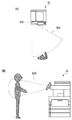
図3は、人感センサ部600の検知エリアを示す図である。人感センサ部600は、所定の周波数(例えば40KHz)の超音波を放射して、物体に当たって戻ってきた反射波を受信し、放射から受信までに要した時間に基づき、物体までの距離を推定する。図3の(a)はMFP10を上面から見た図、同(b)は側面から見た図であり、扇形の部分620が検知エリアを示している。本実施例では、人感センサ部600の検知エリアを、MFP10の正面(或いは正面やや下向き)に設定し、人体に当たって反射した超音波を検知するようにしている。そして、検知エリア620は2段階で、つまり、MFP10の筐体から約2m離れた位置よりも近い距離に存在する人を第1段階として、筐体の約50cm手前で筐体幅と同じ幅の領域内に存在する人を第2段階として、検知可能に設定されているものとする。
FIG. 3 is a diagram showing a detection area of the
図4は、人感センサ部600における各信号の入出力のタイミングを示す図である。まず、マイコン514は、放射ドライバ611を駆動し、併せて内部タイマのカウントを開始させる。また、マイコン514は、アンプ/コンパレータ612からの割り込み受信を開始する。放射ドライバ611は、センサ固有の周波数(ここでは40kHz)でトランスデューサ610を駆動する。なお、本実施例ではトランスデューサ610をDuty比50%で駆動しているが、必ずしも50%でなくてもよい。例えば、トランスデューサ610の駆動開始時からDuty比を段階的に5%、10%・・・といった具合に大きくしてもよい。これにより、トランスデューサ610が発する可聴音を低減させることができる。ここで、トランスデューサ610は放射ドライバ611のバースト駆動(バースト間隔:100msec)とほぼ同時に超音波の検出信号を受信しているが、これはトランスデューサ610から放射される超音波と、トランスデューサ610の残響振動が重なった「直接波」の検出信号である。したがって、受信した検出信号のうち直接波の検出信号を除いた部分が、物体に反射して戻ってきた「反射波」の検出信号である。
FIG. 4 is a diagram showing input / output timing of each signal in the
マイコン514は、放射ドライバ611の駆動開始時刻から、所定の測定時間(ここでは10msec)の間、アンプ/コンパレータ612からの出力信号を割り込み受信する。マイコン514は、反射波による出力信号の割り込み受信までの時間を測定することで、物体までの距離を得ることができる。具体的には、割り込み受信までの時間は、物体までの距離の2倍を音速(ta=25℃では、約340m/sec)で割ったものとなるので、この関係式より物体までの距離が得られる。なお、上述の測定時間10msecは、MFPから約1.7mの範囲内に入った人を認識することを前提にした時間であり、例えばより遠い距離の範囲内に人が侵入した時点で認識できるようにしたい場合は測定時間をさらに長くすればよい。
The microcomputer 514 interrupts and receives the output signal from the amplifier /
<ユーザ検知処理>
図5は、本実施例に係る、MFP10のマイコン514が実行する、スリープモード下におけるユーザ検知処理の流れを示すフローチャートである。マイコン514は、図5のフローに示すユーザ検知処理を所定時間(例えば100msec)間隔で実行する。なお、このフローでは、本発明の目的である静止物体による誤検知を抑制するための制御に絞って必要な処理を記載している点に留意されたい。
<User detection processing>
FIG. 5 is a flowchart showing a flow of user detection processing under the sleep mode executed by the microcomputer 514 of the
ステップ501では、人感センサ部600に対し超音波の放射とその反射波の測定が指示され、測定結果であるアンプ/コンパレータ612の出力信号(デジタル信号)が取得される。具体的には、出力信号がHighからLowに変化(Fall)したタイミング、及びLowからHighに変化(Rise)したタイミングを割り込み受信する。こうして取得した、アンプ/コンパレータ612の出力信号の状態は、検知アリア620内に存在する物体までの距離を表す距離データとして、マイコン514の内部メモリに保存される。図6(a)は、内部メモリに保存される距離データの一例を示す図であり、601はアンプ/コンパレータ612の出力信号、602が距離データを示している。距離データ602において、斜線部分が出力信号のLowに対応する “物体あり”を示し、非斜線部分が出力信号のHighに対応する“物体なし”を示している。本実施例のマイコン514は、測定時間10msec分の距離データを保存するための領域を内部メモリに確保している。ここで、音速=340m/secと仮定し、10msecを距離に換算すると、340(m/sec)×10(msec)/2=1.7mとなる。この場合、マイコン514は、MFP10の前方1.7mまでの物体の存否を認識可能となる(図6(b)を参照)。ここで、距離データは、測定時間10msecをその1/100単位に分割した全100個の要素が時系列に並んだ配列構造を有している。このとき、単位距離に相当する1個の要素は17mm(10msec/100=100μsec)を表すこととなる。なお、より細かく距離をサンプリングしたい場合は、測定時間当たりの分割数を大きく(分割単位を小さく)すればよい。
In step 501, the
ステップ502では、取得した距離データに対しノイズ除去処理が実行される。トランスデューサ610には、例えばスプレー噴射等による高周波音など様々なノイズが混入し得るため、マイコン514が受信するデジタル信号にもこれらノイズが含まれ得る。そこで、本ステップにおいて、ステップ501で取得した距離データに含まれるノイズを除去する。例えば、アンプ/コンパレータ612から受け取るデジタル信号のFall割り込み及びRise割り込みの間隔が狭すぎる場合や逆に広すぎる場合、それらをノイズと判断して距離データから取り除く。ノイズの判定基準としては、人体からの反射波の場合における前述の要素数が実験等によって仮に10個〜15個程度であったとき、例えば3個以下を狭すぎする、20個以上を広すぎるといった具合に閾値を設定しておけばよい。そして、二値画像処理における一般的なフィルタリング手法である、オープニング(膨張処理)・クロージング(収縮処理)等を適用して、ノイズと判断された部分を除去すればよい。図6(a)に示す距離データ602において、参照符号604は存在しないはずの物体を検出したと推測される部分を示し、参照符号605は存在するはずの物体を検出できなかったと推測される部分を示しており、いずれもノイズと判断される。これらノイズと判断される部分604及び605を除去したものが、図6(a)に示す距離データ603である。ノイズ除去後の距離データは、現在フレームの距離データとして、再び内部メモリに保存される。なお、人感センサ部600の出力信号にノイズが含まれる可能性が低い場合は、本ステップを省略してもよい。
In
ステップ503では、上記現在フレームの距離データと予め取得・保存された背景データとが内部メモリから読み出され、両者の間に差分があるかどうかが判定される。ここで、背景データとは、検知エリア620内にある静止物体の位置を示す距離データのことである。この背景データは、人感センサ部600を用いて生成され、直接波の情報の他、検知エリア620内に存在する静止物体(例えば、柱や仮置きされた荷物等)に由来する反射波の情報が含まれることになる。この背景データの取得については後述する。図7(a)は複数の時点における距離データと背景データとの関係を示す図であり、同(b)は当該複数の時点におけるMFP10に近づく人の位置関係を示す図である。まずt5の時点では、人は検知エリア620の範囲外に居る。そのため、t5の時点で得られる距離データ701は背景データ700と等しく、両データの間に差分はない。これに対し、t4〜t0の各時点では、人が検知エリア620内に存在しており、t4からt0にかけて段階的に人がMFP10に接近している。そのため、t4〜t0の各時点では背景データ700と各距離データ702〜706との間で差分が生じている。両データを比較した結果、差分があれば、検知エリア620内に動体(人体)が存在するものとして、ステップ504に進む。一方、差分がなければ、検知エリア620内に動体(人体)が存在しないものとして、ステップ505に進む。
In step 503, the distance data of the current frame and the background data acquired / saved in advance are read from the internal memory, and it is determined whether or not there is a difference between the two. Here, the background data is distance data indicating the position of a stationary object in the
ステップ504では、ステップ503で存在すると判定された動体(物体)までの距離を表す情報(距離情報)が内部メモリに保存される。例えば、前述の図7において、t0の時点における動体までの距離は、1要素分の距離である17mmに当該動体までの要素数である14を乗じた値、17×14=238mmである。したがって、この238mmの情報がt0時点の距離情報として内部メモリに保存される。なお、前述の通り、検出した物体までの距離は、超音波が放射されてから人体に反射して戻ってくるまでの往復に要した時間に等しいことから、距離に換算する前の時間情報を、距離情報として保存してもよい。こうして内部メモリには、現在のフレームから所定数のフレームを遡った過去一定期間分(例えば、過去の20フレーム分:20×100msec=2.0sec分)の距離情報が時系列に保存される。マイコン514は、この時系列に保存された距離情報を解析することで(後述のステップ506)、検知エリア620内にMFP10の使用意図が推認されるユーザが居るかどうかを判定する。なお、保存するフレーム数は任意であり、保存するフレーム数が多いほど検知エリア620の過去の状態を詳しく知ることが可能になるが、より多くのメモリ領域の確保が必要となる。
In
ステップ505では、検知エリア620内に動体が存在しないことを示す距離情報(例えば距離を表す値として無効な値)が内部メモリに保存される。なお、動体の不存在を把握できればよく、通常の距離値とは形式の異なる情報(例えばフラグ)であってもよい。
In step 505, distance information (for example, an invalid value indicating a distance) indicating that no moving object exists in the
ステップ506では、検知エリア620内にMFP10の使用意図が推認されるユーザが存在するかどうかの判定がなされる。具体的には、現時点から遡った過去一定期間分(ここでは直近の20フレーム分)の距離情報を内部メモリから読み出し、当該読み出した距離情報に基づき、動体(人体)の時系列な変化を解析して、検知エリア620内の動体がMFP10を使用する意思のあるユーザであるか否かが判定される。この解析には、例えば、単純なパターンマッチングやDPマッチング、もしくは、隠れマルコフモデルやニューラルネットワーク等の機械学習といった公知の手法を用いればよい。所定数のフレーム分遡った過去から現在までの距離情報の変化を解析することにより、ユーザの接近或いは離脱を判定することができる。
In step 506, it is determined whether or not there is a user in the
ステップ507では、ステップ506での判定結果に従って処理の切り分けがなされる。まず、MFP10の使用意図が推認されるユーザが検知エリア620内に存在するとの判定結果であった場合は、前述の割り込み信号Cが電源制御部211に対して出力される。電源制御部211は、この割り込み信号Cに応答してスリープモードを解除して、スタンバイモードに移行する。これにより、MFP10はユーザが利用可能な状態となる。一方、MFP10の使用意図が推認されるユーザが検知エリア620内に存在しないとの判定結果であった場合は、本処理を抜ける。
In step 507, the processing is divided according to the determination result in step 506. First, when it is determined that the user whose intention to use the
以上が、スリープモード下におけるユーザ検知処理の内容である。なお、本実施例では、スリープモードからスタンバイモードに復帰する場面を念頭に説明を行ったが、本発明を適用可能な場面はこれに限定されない。例えば、同様の処理をスタンバイモード下で行って、ユーザが検知エリアから離脱したと判定した場合に電源制御部211に通知するように構成し、当該通知を受けて電源制御部211が、電力モードをスリープモードに変更するようにしてもよい。
The above is the content of the user detection process in the sleep mode. In the present embodiment, the description has been made with the scene of returning from the sleep mode to the standby mode in mind, but the scene to which the present invention can be applied is not limited to this. For example, the same processing is performed in the standby mode so that the power
<背景データ取得処理>
続いて、前述のステップ503の判定処理で参照される、背景データの取得について説明する。図8は、背景データ取得処理のフローチャートである。この背景データ取得処理は、例えば、MFP10の電源投入時や人感センサ機能がオフからオンに変更されたタイミングで、マイコン514が実行する。前述のユーザ検知処理の実行に先立って背景データを用意しておく必要があることから、上述のようなタイミングで実行されるように制御される。なお、取得した背景データをROMやHDDといった不揮発性メモリに保存しておくことで、電源投入等の度に背景データの取得処理が繰り返されるのを回避できる。
<Background data acquisition process>
Subsequently, the acquisition of the background data referred to in the determination process of step 503 described above will be described. FIG. 8 is a flowchart of the background data acquisition process. This background data acquisition process is executed by the microcomputer 514, for example, when the power of the
ステップ801では、背景データの生成に必要な所定フレーム数以上の距離データが取得済みであるか否かが判定される。所定フレーム数としては、例えば5〜10が設定される。所定フレーム数が多いほど高精度の背景データを得られることになるが、その分処理に時間を要し消費するメモリ量も増えるため、そのトレードオフを考慮して決定すればよい。所定フレーム数以上の距離データが取得済みである場合は、ステップ806に進む。一方、取得済みの距離データが所定フレーム数未満である場合は、ステップ802に進む。
ステップ802では、距離データの取得タイミングが到来しているかどうかが判定される。距離データの取得は所定間隔(例えば100msec)で実行されるように設定され、マイコン514内のタイマ(不図示)によって、取得タイミングの到来が確認されると、ステップ803に進む。
In step 801 it is determined whether or not the distance data of a predetermined number of frames or more necessary for generating the background data has been acquired. For example, 5 to 10 are set as the predetermined number of frames. As the number of predetermined frames increases, more accurate background data can be obtained, but the processing takes time and the amount of memory consumed increases accordingly, so the determination may be made in consideration of the trade-off. If the distance data of the predetermined number of frames or more has been acquired, the process proceeds to step 806. On the other hand, if the acquired distance data is less than the predetermined number of frames, the process proceeds to step 802.
In step 802, it is determined whether or not the acquisition timing of the distance data has arrived. The acquisition of the distance data is set to be executed at a predetermined interval (for example, 100 msec), and when the arrival of the acquisition timing is confirmed by the timer (not shown) in the microcomputer 514, the process proceeds to step 803.
ステップ803では、前述の図5のフローにおけるステップ501と同様、人感センサ部600に対し超音波の放射とその反射波の測定が指示され、測定結果であるアンプ/コンパレータ612の出力信号(デジタル信号)が距離データとして取得される。続くステップ804では、前述の図5のフローにおけるステップ502と同様、取得した距離データに対しノイズ除去が施される。そして、ステップ805で、ノイズが除去された距離データが内部メモリに保存されると、ステップ801に戻る。なお、前述の図5のフローと同様、人感センサ部600の出力信号にノイズが含まれる可能性が低い場合、ノイズ除去の実行を省略してもよい。また、前述のユーザ検知処理ではノイズ除去処理を実行しつつ、背景データ取得処理では、あえてノイズ除去処理を実行しないように構成してもよい。これにより、動体の誤検知を低減させる効果が期待できる。
In
ステップ806では、所定フレーム数の全距離データを用いて背景データが生成される。具体的には、内部メモリから全距離データを読み出し、当該読み出した全距離データを要素ごとにOR合成(論理和)する。この他、全距離データの要素ごとに「物体あり」と判定された回数を求め、「物体あり」と判定された割合が一定以上の要素のみを最終的に「物体あり」の要素とすることで背景データを生成してもよい。図9は、複数の距離データのOR合成によって生成された背景データの一例を示す図である。このようにして生成された背景データは、ステップ807でマイコン514の内部メモリ等に保存され、本処理を終える。以上が、背景データ取得処理の内容である。 In step 806, background data is generated using the total distance data of a predetermined number of frames. Specifically, the total distance data is read from the internal memory, and the read total distance data is OR-combined (logically) for each element. In addition, the number of times that "there is an object" is determined for each element of the total distance data is calculated, and only the elements for which the ratio of "there is an object" is determined to be "with an object" is finally set as the element of "with an object". You may generate background data with. FIG. 9 is a diagram showing an example of background data generated by OR synthesis of a plurality of distance data. The background data generated in this way is stored in the internal memory of the microcomputer 514 or the like in step 807, and the present process is completed. The above is the content of the background data acquisition process.
<変形例>
上述した実施例では、背景データの取得を行うタイミングとして、MFP10の電源投入時や人感センサ機能がオフからオンに変更される時を例示した。しかし、背景データ取得処理を実行するタイミングはこれらに限られない。ここでは、MFP10の電力モードがスリープモードであり、かつ、ユーザを検知した状態が一定時間継続したタイミングで、背景データの取得処理を実行する態様を変形例として説明する。これは、MFP10を使用したユーザがMFP10の目の前に例えば段ボール箱等の荷物を置いて立ち去ったようなケースを想定している。本変形例に係るタイミングで背景データ取得処理を実行することで、検知エリア620内に存在し続ける静止物体が背景データに反映され、当該静止物体が人体として誤検知されるのを防ぐことができる。
<Modification example>
In the above-described embodiment, the timing of acquiring the background data is exemplified when the power of the
図10は、本変形例に係る場面を想定した、人感センサ部600の検知状態の変化及びMFP10の電力モードの変化を時系列に示した図である。マイコン514は、t0〜t22の各時点において、前述のユーザ検知処理を実行し、検知エリア620内に動体が存在するか(ステップ503)、動体が存在した場合にその動体はMFP10の使用意思が推認されるユーザか(ステップ506)を判断している。以下、図10に沿って詳しく説明する。
FIG. 10 is a diagram showing changes in the detection state of the
まず、t1の時点において、マイコン514は、背景データとその時点における距離データとを比較し、検知エリア620内に侵入した動体(ここではユーザが抱える荷物)を検知する。そして、当該動体までの距離情報として1500mmが保存される。ただし、このt1の時点では、検知した動体が、MFP10を使用するであろうユーザであるとは判定されない。
First, at the time of t1, the microcomputer 514 compares the background data with the distance data at that time, and detects a moving object (here, a baggage carried by the user) that has invaded the
次に、t3の時点において、マイコン514は、背景データとその時点における距離データとを比較して動体を検知し、さらに、過去20フレーム分の距離情報を解析し、検知した動体がMFP10の使用するであろうユーザであると判定する。この場面でユーザは、MFP10の操作に先立ち、荷物をMFP10の正面500mmの位置に置いている。
Next, at the time of t3, the microcomputer 514 compares the background data with the distance data at that time to detect a moving object, further analyzes the distance information for the past 20 frames, and the detected moving object uses the
そして、t5の時点でユーザがMFP10の操作を終え、MFP10の不使用状態が所定時間(例えば120sec)経過すると、t7の時点でメインコントローラ200内のCPU221はその事実を検知し、電力モードをスタンバイモードからスリープモードに移行させる。しかし、このt7の時点でマイコン514は、ユーザが置き去りにした荷物を検知し続けている。つまり、ユーザが検知エリア620から離れたにも関わらず、ユーザが存在し続けているとの誤検知状態が継続している。そして、電力モードがスリープモード下で、ユーザ検知状態の一定時間継続(例えば60sec)をマイコン514が検知すると、背景データ取得処理が実行される(図10中の太矢印)。これにより、MFP10の前方500mmの位置に静止物体が置かれた状態で背景データが生成されることになる。この結果、t8の時点以降のt21の時点において、MFP10に再びユーザが接近した場合に、マイコン514はMFP10の前方500mmの位置に置かれた静止物体の影響を受けずに、動体の存否等を判断できる。このように、スリープモード下で、ユーザを検知した状態が一定時間継続したタイミングで背景データの再取得を行うことで、MFP10の前に荷物等が放置された場合でも、これをユーザと誤検知してしまうのを防ぐことができる。
Then, when the user finishes the operation of the
なお、背景データ取得処理の実行タイミングとしては、さらに下記のようなタイミングが考えられる。
1)人感センサ部600から得られる距離データが一定時間変化なしと判断された時点
2)MFP10がスタンバイモードからスリープモードに移行した時点
3)ユーザ或いはサービスマン等の管理者が指示した時点
上記3)の例としては、例えば以下のようなケースがある。
・操作部500や外部PC等を介して、背景データ取得処理の実行が指示された場合
・背景データ取得処理の実行タイミングとして予め指定・登録された日時が到来した場合
The following timings can be further considered as the execution timing of the background data acquisition process.
1) When the distance data obtained from the
-When the execution of the background data acquisition process is instructed via the
以上の通り、本実施例によれば、測距型センサを用いた人体検知において、静止物体による誤検知を防止して、プリンタ等の電子機器に接近する或いは離れるユーザを正確に検知することができる。 As described above, according to the present embodiment, in the human body detection using the distance measuring sensor, it is possible to prevent false detection by a stationary object and accurately detect a user approaching or leaving an electronic device such as a printer. can.
人体等の動体を正確に検知するためには、人感センサ部600の検知エリア内に人が存在しない状態で背景データを生成・取得することが重要である。この点、背景データ取得処理の実行時に検知エリア内に人が存在しないことを常に保証するのは困難である。例えば、サービスマン等の管理者がMFP10とは離れた場所にあるPC等から背景データ取得処理の指示を行う場合には、MFP10の前に人が存在しないことを確認できないこともあり得る。また、背景データ取得処理の実行日時を予め指定しているようなケースでは、その実行時点で検知エリア内に人が居るかどうかを事前に把握することは困難である。
In order to accurately detect a moving object such as a human body, it is important to generate and acquire background data in a state where no person exists in the detection area of the
そこで、ユーザ検知処理の中で背景データを更新する態様を、実施例2として説明する。なお、実施例1と共通する内容については説明を省略ないしは簡略化し、以下では差異点を中心に説明を行うものとする。 Therefore, a mode for updating the background data in the user detection process will be described as the second embodiment. The contents common to the first embodiment will be omitted or simplified, and the differences will be mainly described below.
図11は、背景データの更新を説明する図である。ここでは、背景データ取得処理が実行された時にたまたまユーザがMFP10の前に居たという場面を想定している。図11(a)において、左側は背景データの時系列的な変化、右側は距離データの時系列的な変化をそれぞれ示し、前述の図6と同様、斜線部分の各要素が“物体あり”を示し、非斜線部分の各要素が“物体なし”を示している。なお、本実施例に係る背景データには、物体のあり/なしを表す情報に加え、各要素が“物体あり”の場合、その要素には所定の変数N(N>1)が与えられる。図11の例では、変数Nの値を10としているがこれに限定されない。以下、図11に沿って説明する。
FIG. 11 is a diagram illustrating updating of background data. Here, it is assumed that the user happened to be in front of the
まず、t11の時点では、ユーザはMFP10の面前に存在したままである(図11(b)を参照)。よって、t11の時点の距離データには、人からの反射波による“物体あり”を示す4つの要素が存在している。また、t11の時点の背景データにも、人からの反射波による“物体あり”を示す4つの要素が存在している。このt11の時点における斜線の各要素は、上述の変数Nの値として“10”を保持している。 First, at t11, the user remains in front of the MFP 10 (see FIG. 11B). Therefore, the distance data at the time of t11 has four elements indicating "there is an object" due to the reflected wave from a person. In addition, the background data at the time of t11 also has four elements indicating "there is an object" due to the reflected wave from a person. Each element of the diagonal line at the time of t11 holds "10" as the value of the above-mentioned variable N.
次に、t10の時点では、ユーザはMFP10の面前から離れて既に検知エリア620の外に位置している(図11(b)を参照)。よって、t10の時点の距離データには、人からの反射波による“物体あり”の要素は存在しない。このタイミングで、マイコン514は、背景データ更新処理を行う。具体的には、t11時点の背景データの各要素と、t10時点の距離データの各要素とを比較し、t11時点の背景データ内の“物体あり”の要素が、t10時点の距離データ内で“物体なし”の場合、当該要素における変数Nをデクリメント(1減算)する。この結果、t10の時点の背景データにおける“物体あり”を示す4つの要素内の変数Nの値が“10”から“9”になる。
Next, at the time of t10, the user is already located outside the
そして、t9の時点では、ユーザはMFP10からさらに離れた場所に位置している(図11(b)を参照)。よって、t9の時点の距離データには、人からの反射波による“物体あり”の要素は存在しない。このタイミングでもマイコン514は背景データ更新処理を行う結果、t9の時点の背景データにおける“物体あり”を示す4つの要素内の変数Nの値が“9”から“8”になる。以降、同様の処理が繰り返され、変数Nの値が“0”になったとき、“物体あり”を示す斜線の要素は“物体なし”を示す非斜線の要素に変更される。こうして、t1の時点では、人がMFP10から離れたことを反映した背景データが得られる。
Then, at the time of t9, the user is located further away from the MFP 10 (see FIG. 11B). Therefore, the distance data at the time of t9 does not have an element of "with an object" due to the reflected wave from a person. Even at this timing, as a result of the background data update processing by the microcomputer 514, the value of the variable N in the four elements indicating "there is an object" in the background data at the time of t9 changes from "9" to "8". After that, the same process is repeated, and when the value of the variable N becomes “0”, the diagonal line element indicating “with object” is changed to the non-diagonal element indicating “without object”. In this way, at the time of t1, background data reflecting that the person has left the
以上をまとめると、背景データの更新は以下のような手順でなされる。まず、現時点における背景データの各要素と、直近の測定で得られた直前フレームの距離データの各要素とを比較する。そして、背景データ内の要素が“物体あり”を示す情報を保持している場合に、当該要素に対応する距離データ内の要素が“物体なし”を示す情報を保持する場合、背景データ内の当該要素における変数Nの値をデクリメントする。そして、変数Nの値が0になると、背景データ内の当該要素を“物体なし”を示す情報を保持する要素に変更する。以上のような更新処理によって、検知エリア620内に人が存在する状態で背景データ取得処理を実行した場合であっても、その人がその場所から離れれば、その状態を背景データに反映させることができる。
Summarizing the above, the background data is updated by the following procedure. First, each element of the background data at the present time is compared with each element of the distance data of the immediately preceding frame obtained in the latest measurement. Then, when the element in the background data holds the information indicating "with an object" and the element in the distance data corresponding to the element holds the information indicating "without an object", the background data Decrement the value of the variable N in the element. Then, when the value of the variable N becomes 0, the element in the background data is changed to an element that holds information indicating "no object". Even if the background data acquisition process is executed while a person exists in the
図12は、本実施例に係る、背景データ更新処理を含むユーザ検知処理の流れを示すフローチャートである。ステップ1201〜ステップ1205は、実施例1の図5のフローにおけるステップ501〜ステップ505に対応する。すなわち、取得した距離データに対してノイズ除去を行い(S1201及びS1202)、ノイズ除去後の距離データと予め用意された背景データとを比較して、両データ間の差分に応じた距離情報が保存される(S1203〜S1205)。 FIG. 12 is a flowchart showing the flow of the user detection process including the background data update process according to the present embodiment. Steps 1201 to 1205 correspond to steps 501 to 505 in the flow of FIG. 5 of Example 1. That is, noise is removed from the acquired distance data (S1201 and S1202), the distance data after noise removal is compared with the background data prepared in advance, and the distance information corresponding to the difference between the two data is saved. (S1203 to S1205).
本実施例では、検知エリア620内に動体が存在せず(S1203でNo)、その事実を示す距離情報が保存された後に(S1205)、ステップ1206にて上述した背景データの更新処理が実行される。以降のステップ1207〜ステップ1209は、実施例1の図5のフローにおけるステップ506〜ステップ508に対応し、特に異なるところはないので説明を省く。 In this embodiment, there is no moving object in the detection area 620 (No in S1203), and after the distance information indicating that fact is saved (S1205), the background data update process described above is executed in step 1206. NS. Subsequent steps 1207 to 1209 correspond to steps 506 to 508 in the flow of FIG. 5 of the first embodiment, and there is no particular difference, so description thereof will be omitted.
なお、図12のフローでは、距離データを取得する度(毎フレームにおいて)に、背景データ更新処理を実行するようにしているが、例えば1回おきに実行するなど、背景データの更新を実行しないフレームがあってもよい。 In the flow of FIG. 12, the background data update process is executed every time the distance data is acquired (at each frame), but the background data is not updated, for example, every other time. There may be a frame.
本実施例によれば、検知エリア内に人が存在する状態で背景データが生成・取得された場合であっても、背景データの更新を頻繁に行うことで、その人がその場所から離れれば、その状態を背景データに反映させることができる。これによって、検知エリア内に再び人が現れた場合に、距離データと背景データとの間に差分が生じやすくなり、ユーザを高精度に検知することが可能となる。 According to this embodiment, even when the background data is generated / acquired in the state where the person exists in the detection area, if the person moves away from the place by frequently updating the background data. , The state can be reflected in the background data. As a result, when a person appears again in the detection area, a difference is likely to occur between the distance data and the background data, and the user can be detected with high accuracy.
なお、上述の各実施例で示したマイコン514が実行する処理は、GPU(Graphics Processing Unit)、ASIC(Application Specific Integrated Circuit)、FPGA(Field-Programmable Gate Array)等で実現してもよい。また、実行する処理の一部がハードウェア化されていてもよい。 The processing executed by the microcomputer 514 shown in each of the above-described embodiments may be realized by a GPU (Graphics Processing Unit), an ASIC (Application Specific Integrated Circuit), an FPGA (Field-Programmable Gate Array), or the like. In addition, a part of the processing to be executed may be hardwareized.
また、上述の各実施例では、本発明を適用可能な電子機器の一例として多機能プリンタを用いて説明したが、本発明を適用可能な電子機器はこれに限定されるものではない。例えば、超音波センサ等の測距型センサによって物体検知を行うパーソナルコンピュータ、家電製品等であってもよい。 Further, in each of the above-described embodiments, the multifunction printer has been described as an example of the electronic device to which the present invention can be applied, but the electronic device to which the present invention can be applied is not limited to this. For example, it may be a personal computer, a home appliance, or the like that detects an object by a distance measuring sensor such as an ultrasonic sensor.
(その他の実施例)
本発明は、上述の実施形態の1以上の機能を実現するプログラムを、ネットワーク又は記憶媒体を介してシステム又は装置に供給し、そのシステム又は装置のコンピュータにおける1つ以上のプロセッサがプログラムを読出し実行する処理でも実現可能である。また、1以上の機能を実現する回路(例えば、ASIC)によっても実現可能である。
(Other Examples)
The present invention supplies a program that realizes one or more functions of the above-described embodiment to a system or device via a network or storage medium, and one or more processors in the computer of the system or device reads and executes the program. It can also be realized by the processing to be performed. It can also be realized by a circuit (for example, ASIC) that realizes one or more functions.
Claims (20)
生成された前記距離データと前記所定範囲にある静止物体までの距離を示す背景データとの差分に基づいて前記所定範囲に人が存在するかどうかを判定する判定手段と、
前記判定手段による判定の結果に基づき、第1の電力状態よりも消費電力の小さい第2の電力状態から前記第1の電力状態に移行させる制御手段と、
を備えることを特徴とする情報処理装置。 A generation means that measures a predetermined range with a distance measuring sensor and generates distance data indicating the distance to an object in the predetermined range.
A determination means for determining whether or not a person exists in the predetermined range based on the difference between the generated distance data and the background data indicating the distance to the stationary object in the predetermined range.
Based on the result of the determination by the determination means, the control means for shifting from the second power state, which consumes less power than the first power state, to the first power state,
An information processing device characterized by being equipped with.
前記背景データは、前記情報処理装置の電力状態を前記第2の電力状態に移行させる条件を満たしたときに、前記保存手段に保存される、ことを特徴とする請求項1に記載の情報処理装置。 Further provided with a storage means for storing the background data,
The information processing according to claim 1 , wherein the background data is stored in the storage means when the condition for shifting the power state of the information processing device to the second power state is satisfied. Device.
前記第2の電力状態のときに所定期間中に生成された前記距離データと前記保存手段に保存された前記背景データとに少なくとも基づき、前記情報処理装置の電力消費状態を前記第2の電力状態から前記第1の電力状態に移行させる、
ことを特徴とする請求項2に記載の情報処理装置。 The control means
Based on at least the distance data generated during the predetermined period and the background data stored in the storage means in the second power state, the power consumption state of the information processing apparatus is set to the second power state. To shift to the first power state,
The information processing apparatus according to claim 2.
前記判定手段は、前記保存手段に保存された前記背景データを用いて、前記判定を行う、
ことを特徴とする請求項1に記載の情報処理装置。 The background data is stored in the storage means when an instruction to turn on the power of the information processing device is received from the user or the administrator.
The determination means makes the determination using the background data stored in the storage means.
The information processing apparatus according to claim 1.
前記判定手段は、前記保存手段に保存された前記背景データを用いて、前記判定を行う、
ことを特徴とする請求項1に記載の情報処理装置。 The background data is stored in the storage means when receiving an instruction from the user or the administrator to enable the function of the distance measuring sensor.
The determination means makes the determination using the background data stored in the storage means.
The information processing apparatus according to claim 1.
前記第2の電力状態のときに所定期間中に生成された距離データと前記保存手段に保存された前記背景データとに少なくとも基づいて前記判定を行い、
前記制御手段は、前記判定手段による判定の結果に基づき、前記情報処理装置における電力消費状態を前記第2の電力状態から前記第1の電力状態に移行させる、
ことを特徴とする請求項11又は12に記載の情報処理装置。 The determination means
The determination is made based on at least the distance data generated during the predetermined period in the second power state and the background data stored in the storage means.
The control means shifts the power consumption state in the information processing apparatus from the second power state to the first power state based on the result of the determination by the determination means.
The information processing apparatus according to claim 11 or 12.
生成された前記距離データと前記所定範囲にある静止物体までの距離を示す背景データとの差分に基づいて前記所定範囲に人が存在するかどうかを判定する判定ステップと、
前記判定ステップによる判定の結果に基づき、第1の電力状態よりも消費電力の小さい第2の電力状態から前記第1の電力状態に移行させる制御ステップと、
を有することを特徴とする制御方法。 A generation step of measuring a predetermined range with a distance measuring sensor and generating distance data indicating a distance to an object in the predetermined range, and a generation step.
A determination step for determining whether or not a person exists in the predetermined range based on the difference between the generated distance data and the background data indicating the distance to the stationary object in the predetermined range.
Based on the result of the determination by the determination step, the control step of shifting from the second power state, which consumes less power than the first power state, to the first power state,
A control method characterized by having.
所定範囲を測距型センサで測定して当該所定範囲にある物体までの距離を示す距離データを生成するステップと、
生成された前記距離データと前記所定範囲にある静止物体までの距離を示す背景データとの差分に基づいて前記所定範囲に人が存在するかどうかを判定するステップと、
ユーザまたは管理者から所定の指示を受信した場合に、所定期間中に生成された前記背景データを保存手段に保存するステップと、
前記保存手段に保存された前記背景データ及び前記第2の電力状態のときに前記所定期間中に生成された前記距離データを用いた前記判定の結果に少なくとも基づき、前記情報処理装置における電力消費状態を、制御手段によって前記第2の電力状態から前記第1の電力状態に移行させるステップと、
を含むことを特徴とする制御方法。 A control method for an information processing device capable of shifting to a first power state and a second power state in which power consumption is smaller than that of the first power state.
A step of measuring a predetermined range with a distance measuring sensor and generating distance data indicating a distance to an object in the predetermined range, and a step of generating distance data.
A step of determining whether or not a person exists in the predetermined range based on the difference between the generated distance data and the background data indicating the distance to the stationary object in the predetermined range.
When a predetermined instruction is received from the user or the administrator, the step of saving the background data generated during the predetermined period in the storage means, and
The power consumption state in the information processing apparatus is based on at least the result of the determination using the background data stored in the storage means and the distance data generated during the predetermined period at the time of the second power state. With the step of shifting from the second power state to the first power state by the control means.
A control method comprising.
Priority Applications (4)
| Application Number | Priority Date | Filing Date | Title |
|---|---|---|---|
| JP2016150367A JP6929028B2 (en) | 2016-07-29 | 2016-07-29 | Devices, methods and programs that detect people using range-finding sensors |
| US15/642,678 US10120071B2 (en) | 2016-07-29 | 2017-07-06 | Apparatus that detects person by using sonic sensor, method, electronic apparatus that includes the detection apparatus, and storage medium |
| CN201710633047.5A CN107664762B (en) | 2016-07-29 | 2017-07-28 | Information processing apparatus, method of detecting presence of person around the same, and storage medium |
| US16/142,741 US10317527B2 (en) | 2016-07-29 | 2018-09-26 | Apparatus that detects person by using sonic sensor, method, electronic apparatus that includes the detection apparatus, and storage medium |
Applications Claiming Priority (1)
| Application Number | Priority Date | Filing Date | Title |
|---|---|---|---|
| JP2016150367A JP6929028B2 (en) | 2016-07-29 | 2016-07-29 | Devices, methods and programs that detect people using range-finding sensors |
Publications (3)
| Publication Number | Publication Date |
|---|---|
| JP2018017694A JP2018017694A (en) | 2018-02-01 |
| JP2018017694A5 JP2018017694A5 (en) | 2019-08-22 |
| JP6929028B2 true JP6929028B2 (en) | 2021-09-01 |
Family
ID=61009781
Family Applications (1)
| Application Number | Title | Priority Date | Filing Date |
|---|---|---|---|
| JP2016150367A Active JP6929028B2 (en) | 2016-07-29 | 2016-07-29 | Devices, methods and programs that detect people using range-finding sensors |
Country Status (3)
| Country | Link |
|---|---|
| US (2) | US10120071B2 (en) |
| JP (1) | JP6929028B2 (en) |
| CN (1) | CN107664762B (en) |
Families Citing this family (12)
| Publication number | Priority date | Publication date | Assignee | Title |
|---|---|---|---|---|
| JP6843542B2 (en) * | 2016-07-29 | 2021-03-17 | キヤノン株式会社 | Devices, methods and programs that detect people using ultrasonic sensors |
| US11615623B2 (en) | 2018-02-19 | 2023-03-28 | Nortek Security & Control Llc | Object detection in edge devices for barrier operation and parcel delivery |
| US11295139B2 (en) * | 2018-02-19 | 2022-04-05 | Intellivision Technologies Corp. | Human presence detection in edge devices |
| US10393866B1 (en) * | 2018-03-26 | 2019-08-27 | Cognitive Systems Corp. | Detecting presence based on wireless signal analysis |
| CN109581537B (en) * | 2018-11-23 | 2020-08-25 | 中科传启(苏州)科技有限公司 | Method and device for detecting living body |
| JP7243149B2 (en) * | 2018-11-30 | 2023-03-22 | 京セラドキュメントソリューションズ株式会社 | image forming device |
| CN110031848B (en) * | 2019-03-27 | 2023-03-28 | 乐歌人体工学科技股份有限公司 | Ultrasonic figure identification method |
| CN111160376B (en) * | 2019-12-31 | 2023-11-24 | 联想(北京)有限公司 | Information processing method, device, electronic equipment and storage medium |
| CN113465626A (en) * | 2020-03-31 | 2021-10-01 | 比亚迪半导体股份有限公司 | Image output method and apparatus for navigation, medium, device, and vehicle |
| CN113655881A (en) * | 2021-08-16 | 2021-11-16 | 苏州触达信息技术有限公司 | Shortcut activation system and method based on sound wave control |
| JP2023030343A (en) * | 2021-08-23 | 2023-03-08 | 富士フイルムビジネスイノベーション株式会社 | Image forming apparatus |
| CN115133989A (en) * | 2022-06-27 | 2022-09-30 | 中国电信股份有限公司 | Optical network unit power supply control method and device, storage medium and electronic equipment |
Family Cites Families (19)
| Publication number | Priority date | Publication date | Assignee | Title |
|---|---|---|---|---|
| JP2815553B2 (en) * | 1995-04-28 | 1998-10-27 | 三星電子株式会社 | Video camera with integrated still camera |
| JPH10132928A (en) * | 1996-10-31 | 1998-05-22 | Tokimec Inc | Method and device for detecting moving object |
| IL121068A (en) * | 1997-06-12 | 2000-11-21 | Visonic Ltd | Method and apparatus for detecting the presence of a moving object in a detection area |
| US6550806B1 (en) * | 2000-04-19 | 2003-04-22 | Trw Inc. | Apparatus and method for determining distance utilizing a continuously variable rate sensor for vehicle occupant position sensing |
| EP2374413B1 (en) * | 2002-07-31 | 2017-06-21 | Hitachi, Ltd. | Ultrasonic diagnosis system and strain distribution display method |
| US7450959B2 (en) * | 2003-12-31 | 2008-11-11 | Qualcomm Incorporated | Wireless multiprocessor system-on-chip with unified memory and fault inhibitor |
| JP4727388B2 (en) * | 2005-10-28 | 2011-07-20 | セコム株式会社 | Intrusion detection device |
| JP2008197878A (en) * | 2007-02-13 | 2008-08-28 | Matsushita Electric Ind Co Ltd | Monitoring system, terminal apparatus, control method, and program for it |
| WO2010010782A1 (en) * | 2008-07-22 | 2010-01-28 | 株式会社 日立メディコ | Ultrasonograph and method for calculating coordinates of scanned surface thereof |
| US20120125078A1 (en) * | 2010-11-22 | 2012-05-24 | Webasto Roof Systems Inc. | Sonic wave pinch detection system and method for a movable panel |
| CN102253391B (en) * | 2011-04-19 | 2012-11-28 | 浙江大学 | Multi-laser-radar-based pedestrian target tracking method |
| JP5821419B2 (en) * | 2011-08-30 | 2015-11-24 | 富士通株式会社 | Moving object detection apparatus, moving object detection method, and computer program for moving object detection |
| US8941619B2 (en) * | 2011-11-18 | 2015-01-27 | Au Optronics Corporation | Apparatus and method for controlling information display |
| JP2013179192A (en) * | 2012-02-28 | 2013-09-09 | Canon Inc | Substrate and mounting method |
| JP6406889B2 (en) * | 2014-03-17 | 2018-10-17 | キヤノン株式会社 | Printing apparatus and printing apparatus control method |
| JP6388957B2 (en) * | 2014-04-11 | 2018-09-12 | エスゼット ディージェイアイ テクノロジー カンパニー リミテッドSz Dji Technology Co.,Ltd | Proximity sensing system and method |
| JP6415178B2 (en) * | 2014-08-19 | 2018-10-31 | キヤノン株式会社 | Printing apparatus and data updating method |
| CN105510921B (en) * | 2015-12-30 | 2018-07-17 | 北京新能源汽车股份有限公司 | Safety device for vehicle high-voltage system |
| JP6843542B2 (en) | 2016-07-29 | 2021-03-17 | キヤノン株式会社 | Devices, methods and programs that detect people using ultrasonic sensors |
-
2016
- 2016-07-29 JP JP2016150367A patent/JP6929028B2/en active Active
-
2017
- 2017-07-06 US US15/642,678 patent/US10120071B2/en active Active
- 2017-07-28 CN CN201710633047.5A patent/CN107664762B/en active Active
-
2018
- 2018-09-26 US US16/142,741 patent/US10317527B2/en active Active
Also Published As
| Publication number | Publication date |
|---|---|
| CN107664762A (en) | 2018-02-06 |
| US10317527B2 (en) | 2019-06-11 |
| US20190025424A1 (en) | 2019-01-24 |
| JP2018017694A (en) | 2018-02-01 |
| US20180031700A1 (en) | 2018-02-01 |
| US10120071B2 (en) | 2018-11-06 |
| CN107664762B (en) | 2022-05-10 |
Similar Documents
| Publication | Publication Date | Title |
|---|---|---|
| JP6929028B2 (en) | Devices, methods and programs that detect people using range-finding sensors | |
| US10754288B2 (en) | Image forming apparatus, method for controlling the same, and recording medium | |
| JP3624070B2 (en) | Coordinate input device and control method thereof | |
| US20130258424A1 (en) | Power supply control device, image processing apparatus, and non-transitory computer readable medium storing power supply control program | |
| US10057445B2 (en) | Image forming apparatus and control method of image forming apparatus | |
| US10432815B2 (en) | Information processing apparatus that turns on when sensing a human and turns off when no operation is input in a predetermined time, method of controlling the same, and storage medium | |
| JP6843542B2 (en) | Devices, methods and programs that detect people using ultrasonic sensors | |
| US10452114B2 (en) | Image processing apparatus, method for controlling the same, and storage medium | |
| JP6376804B2 (en) | Image forming apparatus, image forming apparatus control method, and program | |
| JP6480706B2 (en) | Image forming apparatus, control method therefor, and program | |
| US10218863B2 (en) | Information processing apparatus having human presence sensor | |
| US10209358B2 (en) | Object detection using sonic waves | |
| EP2998828B1 (en) | Printing apparatus, method for controlling printing apparatus, and recording medium | |
| JP6897010B2 (en) | Return control device, image processing device and program | |
| JP2017024223A (en) | Image formation apparatus, control method and program of image formation apparatus | |
| JP2009110229A (en) | Handwriting input system | |
| JP2018019024A (en) | Printed board where vibration component for generating vibration | |
| CN112666807A (en) | Image forming apparatus, storage medium, and image forming method | |
| JP2019213040A (en) | Information processing device, control method therefor, and program |
Legal Events
| Date | Code | Title | Description |
|---|---|---|---|
| A521 | Request for written amendment filed |
Free format text: JAPANESE INTERMEDIATE CODE: A523 Effective date: 20190711 |
|
| A621 | Written request for application examination |
Free format text: JAPANESE INTERMEDIATE CODE: A621 Effective date: 20190711 |
|
| A977 | Report on retrieval |
Free format text: JAPANESE INTERMEDIATE CODE: A971007 Effective date: 20200630 |
|
| A131 | Notification of reasons for refusal |
Free format text: JAPANESE INTERMEDIATE CODE: A131 Effective date: 20200901 |
|
| A521 | Request for written amendment filed |
Free format text: JAPANESE INTERMEDIATE CODE: A523 Effective date: 20201006 |
|
| A131 | Notification of reasons for refusal |
Free format text: JAPANESE INTERMEDIATE CODE: A131 Effective date: 20210302 |
|
| A521 | Request for written amendment filed |
Free format text: JAPANESE INTERMEDIATE CODE: A523 Effective date: 20210407 |
|
| TRDD | Decision of grant or rejection written | ||
| A01 | Written decision to grant a patent or to grant a registration (utility model) |
Free format text: JAPANESE INTERMEDIATE CODE: A01 Effective date: 20210706 |
|
| A61 | First payment of annual fees (during grant procedure) |
Free format text: JAPANESE INTERMEDIATE CODE: A61 Effective date: 20210810 |
|
| R151 | Written notification of patent or utility model registration |
Ref document number: 6929028 Country of ref document: JP Free format text: JAPANESE INTERMEDIATE CODE: R151 |