JP6928777B2 - Ventilation device - Google Patents
Ventilation device Download PDFInfo
- Publication number
- JP6928777B2 JP6928777B2 JP2017010912A JP2017010912A JP6928777B2 JP 6928777 B2 JP6928777 B2 JP 6928777B2 JP 2017010912 A JP2017010912 A JP 2017010912A JP 2017010912 A JP2017010912 A JP 2017010912A JP 6928777 B2 JP6928777 B2 JP 6928777B2
- Authority
- JP
- Japan
- Prior art keywords
- air
- bathroom
- living room
- exhaust
- circulating
- Prior art date
- Legal status (The legal status is an assumption and is not a legal conclusion. Google has not performed a legal analysis and makes no representation as to the accuracy of the status listed.)
- Active
Links
- 238000009423 ventilation Methods 0.000 title claims description 36
- 238000007664 blowing Methods 0.000 claims description 23
- 238000001035 drying Methods 0.000 claims description 13
- 238000010981 drying operation Methods 0.000 claims description 9
- 238000011144 upstream manufacturing Methods 0.000 claims description 5
- 238000010438 heat treatment Methods 0.000 description 23
- XLYOFNOQVPJJNP-UHFFFAOYSA-N water Substances O XLYOFNOQVPJJNP-UHFFFAOYSA-N 0.000 description 10
- 238000001704 evaporation Methods 0.000 description 4
- 230000008020 evaporation Effects 0.000 description 4
- 238000011084 recovery Methods 0.000 description 2
- 230000002238 attenuated effect Effects 0.000 description 1
- 239000000470 constituent Substances 0.000 description 1
- 230000006870 function Effects 0.000 description 1
- 238000009434 installation Methods 0.000 description 1
- 238000010030 laminating Methods 0.000 description 1
- 239000000463 material Substances 0.000 description 1
- 229910001120 nichrome Inorganic materials 0.000 description 1
- 230000000644 propagated effect Effects 0.000 description 1
- 239000007921 spray Substances 0.000 description 1
- 238000009834 vaporization Methods 0.000 description 1
- 230000008016 vaporization Effects 0.000 description 1
Images


Landscapes
- Ventilation (AREA)
- Air Humidification (AREA)
Description
本発明は、居室の加湿を行うことができる換気装置に関するものである。 The present invention relates to a ventilation device capable of humidifying a living room.
従来の換気装置には、浴室の湿潤空気を室内空気の加湿に用いることで居室の快適性向上を図ったものがある。その一例として、特許文献1に示す構成がある。以下、その構成について図4を参照しながら説明する。
Some conventional ventilation devices improve the comfort of the living room by using the humid air in the bathroom to humidify the indoor air. As an example, there is a configuration shown in
図4は、従来の加湿装置の構成を示す概略図である。図4に示すように、加湿装置は、図示しない空気調和装置からダクト101を通じて送風される暖房空気を居室102に吹き出す吹出口103を備えている。そして、浴室104内の湿潤空気を吹出口103に送風する湿潤空気搬送手段105を備えている。
FIG. 4 is a schematic view showing the configuration of a conventional humidifier. As shown in FIG. 4, the humidifying device includes an
次に、その動作について説明する。居室102内を暖房するときには、空気調和装置から送風される暖房空気と、湿潤空気搬送手段105によって浴室104から吹出口103に搬送される湿潤空気とを混合させて居室102内に吹出す。このようにして浴室104内の高湿度空気を利用することにより、省エネで居室102の加湿を行うものである。
Next, the operation will be described. When heating the inside of the
しかしながら、上記構成においては、浴室内空気を直接居室内に供給するものであり、浴室のにおい等が居室内に拡散して必ずしも快適性を向上できるものではなかった。 However, in the above configuration, the air in the bathroom is directly supplied to the living room, and the odor of the bathroom and the like are diffused into the living room, and the comfort cannot always be improved.
そこで、本発明は、上記課題を解決し、浴室内の高温高湿度空気を利用した居室の加温加湿を行うことで省エネを実現しながら、快適性を維持できる換気装置を提供するものである。 Therefore, the present invention solves the above-mentioned problems and provides a ventilation device capable of maintaining comfort while realizing energy saving by heating and humidifying a living room using high-temperature and high-humidity air in the bathroom. ..
そして、本発明の換気装置は、浴室内の空気を屋外に排気する排気手段と、居室内の空気を吸気し、吸気した居室内の空気を再び居室内に循環送風する循環送風手段と、を備えた換気装置において、排気手段によって排気される浴室内の空気と循環送風手段によって
送風される居室内の空気との間で熱交換素子を介して温度および湿度の交換が行われる熱交換手段と、浴室内に温風を吹出して浴室内を乾燥させる浴室乾燥手段と、循環送風手段によって送風される居室内の空気を加湿する加湿手段と、を備え、浴室乾燥手段および排気手段を動作させて、浴室を乾燥させる浴室乾燥運転モードと、浴室乾燥運転モードを実行した後に浴室乾燥手段、排気手段、循環送風手段を動作させる予備加湿運転モードと、を備えたものであり、これにより所期の目的を達成するものである。
Then, the ventilation device of the present invention includes an exhaust means for exhausting the air in the bathroom to the outside and a circulating ventilation means for taking in the air in the living room and circulating the air in the inhaled room to the living room again. in ventilation apparatus having a heat exchange means for exchanging the temperature and humidity via heat exchange element is performed between the air in the room that is blown by the air and the circulation air sending means in the bathroom that is exhausted by the exhaust means A bathroom drying means for blowing warm air into the bathroom to dry the inside of the bathroom and a humidifying means for humidifying the air in the living room blown by the circulating air blowing means are provided, and the bathroom drying means and the exhaust means are operated. , A bathroom drying operation mode for drying the bathroom and a pre-humidifying operation mode for operating the bathroom drying means, the exhaust means, and the circulating air blowing means after executing the bathroom drying operation mode . It achieves the purpose.
上記構成により、浴室から屋外へ排気する空気から居室内を循環する空気に温度および湿度を回収することができる。結果として、浴室内の高温高湿度空気を利用した居室の加温加湿を行うことで省エネを実現しながら、快適性を維持できる換気装置を提供することができるものである。 With the above configuration, the temperature and humidity can be recovered from the air exhausted from the bathroom to the outside to the air circulating in the living room. As a result, it is possible to provide a ventilation device that can maintain comfort while realizing energy saving by heating and humidifying a living room using high-temperature and high-humidity air in the bathroom.
以下、本発明の実施の形態を図面に基づいて説明する。ただし、以下に示す実施の形態は、本発明の技術思想を具体化するため例示するものであって、本発明を以下のものに特定しない。また、特許請求の範囲に示される部材を、実施例に記載する部材に特定するものでは決してない。特に実施の形態に記載されている構成部材の寸法、材質、形状、その相対的配置等は特に特定的な記載がない限りは、本発明の範囲をそれのみに限定する趣旨ではなく、単なる説明例にすぎない。なお、各図面が示す部材の大きさや位置関係等は、説明を明確にするため誇張していることがある。さらに以下の説明において、同一の名称、符号については同一もしくは同質の部材を示しており、詳細説明を適宜省略する。また、本発明を構成する各要素は、複数の要素を同一の部材で構成して一の部材で複数の要素を兼用する態様としてもよいし、逆に一の部材の機能を複数の部材で分担して実現することもできる。なお、一部の実施例、実施形態において説明された内容は、他の実施例、実施形態等に利用可能なものもある。 Hereinafter, embodiments of the present invention will be described with reference to the drawings. However, the embodiments shown below are examples for embodying the technical idea of the present invention, and the present invention is not specified as the following. In addition, the members shown in the claims are by no means specified as the members described in the examples. Unless otherwise specified, the dimensions, materials, shapes, relative arrangements, etc. of the constituent members described in the embodiments are not intended to limit the scope of the present invention to that alone, but merely described. It's just an example. The size and positional relationship of the members shown in each drawing may be exaggerated to clarify the explanation. Further, in the following description, members having the same or the same quality are shown with the same name and reference numeral, and detailed description thereof will be omitted as appropriate. Further, each element constituting the present invention may be in a mode in which a plurality of elements are composed of the same member and the plurality of elements are shared by one member, or conversely, the function of one member is performed by the plurality of members. It can also be shared and realized. The contents described in some examples and embodiments can be used in other embodiments and embodiments.
本発明に係る換気装置は、浴室内の空気を屋外に排気する排気手段と、居室内の空気を吸気し、吸気した居室内の空気を再び居室内に循環送風する循環送風手段と、を備えた換気装置において、排気手段によって排気される空気と循環送風手段によって送風される空気との間で熱交換素子を介して熱交換が行われる熱交換手段を備えたものである。 The ventilation device according to the present invention includes an exhaust means for exhausting the air in the bathroom to the outside, and a circulating ventilation means for taking in the air in the living room and circulating the air in the inhaled room to the living room again. The ventilation device is provided with a heat exchange means in which heat exchange is performed between the air exhausted by the exhaust means and the air blown by the circulating blower means via a heat exchange element.
これにより、浴室から屋外へ排気する空気から居室内を循環する空気に温度および湿度を回収することができる。すなわち、浴室内の高温高湿度空気を利用した居室の加温加湿を行うことで省エネを実現しながら、快適性を維持できる換気装置を提供することができるものである。 As a result, the temperature and humidity can be recovered from the air exhausted from the bathroom to the outside to the air circulating in the living room. That is, it is possible to provide a ventilation device that can maintain comfort while realizing energy saving by heating and humidifying a living room using high-temperature and high-humidity air in the bathroom.
また、換気装置は、浴室内に温風を吹出して浴室内を乾燥させる浴室乾燥手段と、循環送風手段によって送風される空気を加湿する加湿手段と、を備え、浴室乾燥手段および排気手段を動作させて、浴室を乾燥させる浴室乾燥運転モードを有し、浴室乾燥運転モードを実行した後に浴室乾燥手段、排気手段、循環送風手段を動作させる予備加湿運転モードを備えた構成としてもよい。 Further, the ventilation device includes a bathroom drying means for blowing warm air into the bathroom to dry the inside of the bathroom and a humidifying means for humidifying the air blown by the circulating air blowing means, and operates the bathroom drying means and the exhaust means. It may be configured to have a bathroom drying operation mode for drying the bathroom, and a pre-humidifying operation mode for operating the bathroom drying means, the exhaust means, and the circulating air blowing means after executing the bathroom drying operation mode.
この構成によって、浴室乾燥手段の動作によって浴室内の空気の温湿度がさらに上昇し、それに伴って循環送風手段によって送風される空気の温湿度も上昇するので、熱交換手段によって居室内に供給する空気に回収される温湿度を増加させることができる。その結果、居室に吹出される気流のコールドドラフト感が低減され快適性をより向上させることができる。 With this configuration, the temperature and humidity of the air in the bathroom further rises due to the operation of the bathroom drying means, and the temperature and humidity of the air blown by the circulating air blowing means also rises accordingly, so that the air is supplied to the living room by the heat exchange means. The temperature and humidity recovered in the air can be increased. As a result, the feeling of cold draft of the airflow blown into the living room is reduced, and the comfort can be further improved.
また、循環送風手段に用いられるファンは、循環送風手段によって送風される風の流れ方向に対して熱交換素子の下流側かつ加湿手段の上流側に設けた構成としてもよい。 Further, the fan used in the circulating air blowing means may be provided on the downstream side of the heat exchange element and on the upstream side of the humidifying means with respect to the flow direction of the air blown by the circulating air blowing means.
この構成によって、循環送風手段のファンの動作によって発生する騒音の居室内への伝搬を抑制することができる。すなわち、循環送風手段のファンによって発生する騒音は、循環送風手段の上流側に設けられた熱交換素子で反射し、この熱交換素子で反射したファンの騒音はファンの下流側に設けられた加湿手段でさらに反射する。一方、加湿手段側に伝搬した騒音は加湿手段で反射し、その反射した音は熱交換素子でさらに反射する。反射を繰り返すことで騒音は減衰するため、居室内へ騒音を伝搬しにくくすることができる。結果として、換気装置をより静音化させることができる。 With this configuration, it is possible to suppress the propagation of noise generated by the operation of the fan of the circulating blower means into the living room. That is, the noise generated by the fan of the circulating blower means is reflected by the heat exchange element provided on the upstream side of the circulating blower means, and the noise of the fan reflected by this heat exchange element is humidified provided on the downstream side of the fan. Further reflection by means. On the other hand, the noise propagated to the humidifying means side is reflected by the humidifying means, and the reflected sound is further reflected by the heat exchange element. Since the noise is attenuated by repeating the reflection, it is possible to make it difficult for the noise to propagate into the living room. As a result, the ventilation system can be made quieter.
また、熱交換素子は、循環送風手段によって送風される空気が通過する第1風路の通風断面積が、排気手段によって排気される空気が通過する第2風路の通風断面積よりも大きくしてもよい。 Further, in the heat exchange element, the ventilation cross-sectional area of the first air passage through which the air blown by the circulating air blowing means passes is larger than the ventilation cross-sectional area of the second air passage through which the air exhausted by the exhaust means passes. You may.
この構成によって、循環送風手段によって送風される空気の風量が排気手段によって排気される空気の風量よりも大きい場合であっても、循環送風手段によって送風される空気が通過する第1風路の通風断面積が、排気手段によって排気される空気が通過する第2風路の通風断面積よりも大きいため、熱交換素子を通過する循環送風手段によって送風される空気の風速を抑えることができる。したがって、熱交換素子を通過する循環送風手段によって送風される空気と排気手段によって排気される空気の風速を均一にすることができ、熱交換手段における熱交換効率を向上させることができる。 With this configuration, even if the air volume of the air blown by the circulating blower means is larger than the air volume of the air exhausted by the exhaust means, the ventilation of the first air passage through which the air blown by the circulating blower means passes. Since the cross-sectional area is larger than the ventilation cross-sectional area of the second air passage through which the air exhausted by the exhaust means passes, the wind speed of the air blown by the circulating blower means passing through the heat exchange element can be suppressed. Therefore, the wind speeds of the air blown by the circulating blower means passing through the heat exchange element and the air exhausted by the exhaust means can be made uniform, and the heat exchange efficiency in the heat exchange means can be improved.
以下、添付図面を参照して、本発明の実施の形態につき説明し、本発明の理解に供する。なお、以下の実施の形態は、本発明を具体化した一例であって、本発明の技術的範囲を限定するものではない。また、全図面を通して、同一の部位については同一の符号を付して説明を省略している。さらに、本発明に直接には関係しない各部の詳細については重複を避けるために、各図面ごとに説明は省略している。 Hereinafter, embodiments of the present invention will be described with reference to the accompanying drawings for the purpose of understanding the present invention. The following embodiments are examples that embody the present invention, and do not limit the technical scope of the present invention. In addition, the same parts are designated by the same reference numerals throughout the drawings, and the description thereof is omitted. Further, in order to avoid duplication, the details of each part not directly related to the present invention are omitted for each drawing.
(実施の形態1)
図1及び図2は本発明の実施形態における換気装置の設置例を示す概略図である。図1に示すように、換気装置の本体1は浴室2の天井裏に設置されている。本体1の下面には浴室に対して開口した浴室吸気口3が設けられている。また、本体1の側面には、本体1内に吸気した浴室2内の空気を屋外へ排気するための排気口4が設けられている。排気口4には、排気ダクト5が接続されており、排気ダクト5の他端は、屋外に設けられた排気フード6に接続されている。
(Embodiment 1)
1 and 2 are schematic views showing an installation example of a ventilation device according to an embodiment of the present invention. As shown in FIG. 1, the
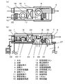
次に、本体1の構成について図2を用いて説明する。図2(a)は、本実施形態の本体1を上方から見たときの内部構成を示す概略断面図であり、図2(b)は、本実施形態の本体1を側方から見たときの内部構成を示す概略断面図である。本体1には、浴室吸気口3と排気口4とを連通する浴室排気風路7と、浴室排気風路7内に送風するための排気ファン8が設けられている。これら浴室吸気口3、排気口4、浴室排気風路7、排気ファン8により、浴室内の空気を屋外に排気する排気手段が構成されている。
Next, the configuration of the
また、本体1の側面には、居室10内の空気を吸気するための居室吸気口11と、居室10から本体1内に吸気した空気を再び居室10に送風するための居室送風口12が設けられている。居室吸気口11には吸気ダクト13が接続されており、吸気ダクト13は居室10に設けられ居室10の空気を吸い込むための吸気口14に接続されている。また、居室送風口12には送風ダクト15が接続されており、送風ダクト15の他端は、居室10に設けられ空気を吹出すため送風口9に接続されている。
Further, on the side surface of the
本体1内には、居室吸気口11と居室送風口12とを連通する居室循環風路16と、居室循環風路16内に送風するための居室循環ファン17が設けられている。これら居室吸気口11、居室送風口12、居室循環風路16、居室循環ファン17により居室10内の空気を吸気し、吸気した居室10内の空気を再び居室10に送風する循環送風手段が構成されている。
In the
また、本体1内には、通過する2種の空気の間で温度および湿度を交換する熱交換素子18が設けられている。熱交換素子18は、居室循環風路16および浴室排気風路7と接続されており、居室循環風路16を通過する空気と、浴室排気風路7を通過する空気との間で温度および湿度を交換することができるものである。
Further, in the
次に、熱交換素子18の詳細構成について図3を用いて説明する。熱交換素子18は、ある一方の面から他方の面に温度を伝達および水分を透過させる伝熱板19を積層して構成されている。伝熱板19間にはそれぞれの伝熱板19の間隔を維持するための後述する第1間隔保持リブ20および第2間隔保持リブ21が設けられており、これにより形成された空間を一層ずつ交互に居室循環風路16を通る空気と、浴室排気風路7を通る空気とを通過させる構成となっている。以後、居室循環風路16を通る空気が通過する風路を第1風路22とし、浴室排気風路7を通る空気が通過する風路を第2風路23と定義する。
Next, the detailed configuration of the
第1風路22の間隔を保持する第1間隔保持リブ20の高さと、第2風路23の間隔を保持する第2間隔保持リブ21の高さは異なるように形成されている。一般に、浴室2の容積よりも居室10の容積のほうが大きく、居室循環ファン17は排気ファン8よりも多くの風量を送風する必要があるため、第1間隔保持リブ20の高さは第2間隔保持リブ21の高さよりも大きく形成されている。
The height of the first
再び図2を用いて本体1の内部構成について説明する。図2(b)の本体1には浴室排気風路7の熱交換素子18を通過せずにバイパスするバイパス風路24が設けられている。バイパス風路24は、浴室排気風路7の浴室吸気口3と熱交換素子18との間に設けられた分岐部から分岐し、浴室排気風路7の熱交換素子18と排気ファン8との間に接続されている。分岐部には風路切換手段25が設けられており、風路切換手段25は、風路切換ダンパーの開閉動作により、浴室吸気口3から吸気した空気を熱交換素子をバイパスするバイパス風路24に流す設定(以下、設定Aとする)と、浴室吸気口3から吸気した空気をそのまま熱交換素子18に流す設定(以下、設定Bとする)かを切り替えることができるものである。
The internal configuration of the
また、本体1下面には浴室吸気口3から本体1内に吸気した空気を浴室2に送風するための浴室吹出口26が設けられている。本体1には、浴室吸気口3と浴室吹出口26とを連通する浴室循環風路27と、浴室循環風路27に送風するための浴室循環ファン28が設けられている。浴室循環風路27内には、浴室循環風路27を通過する空気を加熱する加熱手段29が設けられている。これら浴室吸気口3、浴室吹出口26、浴室循環風路27、加熱手段29、浴室循環ファン28により、浴室内に温風を吹出して浴室内を乾燥させる浴室乾燥手段が構成されている。
Further, a
加熱手段29は、通過する空気を加熱するものであればよく、例えば、自己温度制御性をもつPTCヒータが安全性の観点から望ましいが、それ以外にも、電熱線を用いたニクロムヒータ、シーズヒータなどを用いることができる。 The heating means 29 may be any as long as it heats the passing air. For example, a PTC heater having self-temperature controllability is desirable from the viewpoint of safety, but other than that, a nichrome heater using a heating wire and seeds. A heater or the like can be used.
また、居室循環風路16内には、居室循環風路16内を通過する空気を加湿する加湿手段30が設けられている。加湿手段30は、居室循環ファン17よりも送風される風の流れ方向に対して下流側に設けられ、居室循環ファン17は熱交換素子18よりも送風される風の流れ方向に対して下流側に設けられている。すなわち、熱交換素子18の送風される風の流れ方向に対して下流側かつ加湿手段30よりも送風される風の流れ方向に対して上流側に居室循環ファン17が設けられている。
Further, in the living room
加湿手段30は、通過する空気を加湿するものであればよく、例えば、水分を含んだフィルタに空気を通過させて加湿を行う気化式加湿器が省エネの観点から望ましいが、それ以外にも加熱して水蒸気を発生させて加湿する蒸気式加湿器、微細な水滴を生成し空気と混合させることで加湿する超音波式加湿器、水噴霧式加湿器、水破砕式加湿器などを用いることができる。 The humidifying means 30 may be any one that humidifies the passing air. For example, a vaporization type humidifier that humidifies by passing the air through a filter containing water is desirable from the viewpoint of energy saving, but other than that, heating A steam humidifier that generates steam to humidify, an ultrasonic humidifier that generates fine water droplets and mixes them with air, a water spray humidifier, a water crushing humidifier, etc. can be used. can.
また、本体1内には、居室循環ファン17、浴室循環ファン28、排気ファン8、加熱手段29、加湿手段30の運転、停止を制御する制御手段が複数設けられている。
Further, a plurality of control means for controlling the operation and stop of the living
換気装置の制御手段は、運転モードを入力するリモコン32及びリモコン32により入力された運転モードを実行する制御装置33とから構成されている。制御装置33は、リモコン32に入力された情報をもとに、換気装置の各構成要素である居室循環ファン17、浴室循環ファン28、排気ファン8、加熱手段29、加湿手段30、風路切換手段25の可動を制御する信号を送信する。
The control means of the ventilation device includes a
本実施形態では、排気ファン8をオン状態、居室循環ファン17と浴室循環ファン28と加熱手段29と加湿手段30をオフ状態、風路切換手段25を設定A状態とする浴室換気運転モード、浴室循環ファン28と加熱手段29と排気ファン8をオン状態、居室循環ファン17と加湿手段30をオフ状態、風路切換手段25を設定A状態とする浴室乾燥運転モード、排気ファン8と居室循環ファン17をオン状態、浴室循環ファン28と加熱手段29と加湿手段30をオフ状態、風路切換手段25を設定B状態とする蒸気回収運転モード、居室循環ファン17と加湿手段30をオン状態、浴室循環ファン28と排気ファン8と加熱手段29をオフ状態、風路切換手段25を設定A状態とする加湿運転モード、浴室循環ファン28と排気ファン8と加熱手段29をオン状態、居室循環ファン17と加湿手段30とをオフ状態、風路切換手段25を設定B状態とし、所定の時間が経過した後に、居室循環ファン17と浴室循環ファン28と排気ファン8と加熱手段29をオン状態、加湿手段30をオフ状態、風路切換手段25を設定B状態にする予備加湿運転モードを有している。
In the present embodiment, the bathroom ventilation operation mode in which the
この予備加湿運転モードの詳細動作について説明する。制御手段の運転モードを予備加湿運転モードに設定すると、初めに浴室循環ファン28と加熱手段29と排気ファン8が動作する。すると、浴室に温風が吹出され、浴室内の空気は浴室内壁に付着した水滴の蒸発によって高湿空気となる。この高湿空気は排気ファン8によって浴室排気風路7に吸い込まれ、熱交換素子18を通過して屋外へ排気される(浴室乾燥運転モード)。
The detailed operation of this pre-humidification operation mode will be described. When the operation mode of the control means is set to the pre-humidification operation mode, the
そして、所定の時間が経過した後、加熱手段29、排気ファン8に加えて居室循環ファン17が動作し居室10から吸い込まれた空気が熱交換素子18を通過して居室10に送風される。すると、熱交換素子18の作用により、屋外へ排気される高湿空気から居室に送風される空気に温度および湿度が回収される。居室10に吹出される空気は、屋外へ排気される空気から回収された温度と水分を含んでいるため、居室10内の空気よりも湿度だけでなく温度も高い空気が居室10に吹出される。したがって、加湿運転開始時に感じられるコールドドラフト感を低減した加湿を行うことができる。
Then, after a predetermined time has elapsed, the living
ここでいう所定の時間とは、浴室乾燥運転モードを開始してから浴室2内壁に付着した水滴が蒸発し始めるまでの時間である。これよりも短い時間であると居室の加湿ができない。すなわち、浴室2に温風を吹出した直後は、壁面に付着した水滴の蒸発に温風の熱を奪われるため、浴室排気風路7に吸い込まれる空気の温度が低くなるため、熱交換素子による排気からの温度および湿度の回収ができず、居室の加湿を行うことができないのである。一方、これよりも長い時間であると、浴室の壁面に付着した水滴から蒸発した水分を排気とともに屋外へ排出してしまうので、温度および湿度の回収ロスが生じてしまうのである。
The predetermined time referred to here is the time from the start of the bathroom drying operation mode to the start of evaporation of water droplets adhering to the inner wall of the
この所定の時間は、本装置が設置される浴室の寸法に合わせて予め設定されてあるか、もしくは、浴室排気風路7を通過する空気の温度および湿度を検出し、水滴の蒸発に伴う湿度の変化量を学習することで最適な時間に自動最適化されるものである。
This predetermined time is preset according to the dimensions of the bathroom in which the device is installed, or the temperature and humidity of the air passing through the bathroom
また、居室循環風路16に送風する居室循環ファン17を熱交換素子18よりも送風される風の流れ方向に対して下流側かつ加湿手段30よりも上流側に設けてあるので、居室循環ファン17の動作によって発生する騒音の居室内への伝搬を抑制することができる。
Further, since the living
居室循環ファン17で発生する騒音は居室循環風路16内を伝搬して居室へ放出されるが、居室循環ファン17で発生した騒音は熱交換素子18と加湿手段30との間で反射を繰り返し、次第に減衰するので、居室へ騒音を伝搬しにくくすることができる。
The noise generated by the living
また、第1風路22の第1間隔保持リブ20の高さが第2風路23の第2間隔保持リブ21の高さよりも大きく形成されているので、第1風路22を通過する空気の風速と第2風路23を通過する空気の風速とを均一にすることができる。熱交換素子18を通過する空気の風速を均一にすることで、熱交換効率を向上させ排気からの温度および水分の回収量を最大化することができる。
Further, since the height of the first
以上述べたようにして、浴室の高湿度空気を利用した居室の加湿を行うことで省エネを実現しながら快適性を維持できる換気装置を提供することができるものである。 As described above, it is possible to provide a ventilation device that can maintain comfort while realizing energy saving by humidifying a living room using high-humidity air in a bathroom.
本発明に係る換気装置は、浴室の換気乾燥とともに居室の加湿を行うことができるものであり、浴室用および居室用の換気加湿機器等として有用である。 The ventilation device according to the present invention can humidify a living room as well as ventilate and dry the bathroom, and is useful as a ventilation humidifying device for a bathroom and a living room.
1 本体
3 浴室吸気口
4 排気口
7 浴室排気風路
8 排気ファン
10 居室
11 居室吸気口
12 居室送風口
16 居室循環風路
17 居室循環ファン
18 熱交換素子
20 第1間隔保持リブ
21 第2間隔保持リブ
22 第1風路
23 第2風路
26 浴室吹出口
27 浴室循環風路
28 浴室循環ファン
29 加熱手段
30 加湿手段
32 リモコン
33 制御装置
1
Claims (3)
前記排気手段によって排気される前記浴室内の空気と前記循環送風手段によって送風される前記居室内の空気との間で熱交換素子を介して温度および湿度の交換が行われる熱交換手段と、
前記浴室内に温風を吹出して浴室内を乾燥させる浴室乾燥手段と、
前記循環送風手段によって送風される前記居室内の空気を加湿する加湿手段と、
を備え、
前記浴室乾燥手段および前記排気手段を動作させて、前記浴室を乾燥させる浴室乾燥運転モードと、前記浴室乾燥運転モードを実行した後に前記浴室乾燥手段、前記排気手段、前記循環送風手段を動作させる予備加湿運転モードと、を備えたことを特徴とする換気装置。 In a ventilation device provided with an exhaust means for exhausting the air in the bathroom to the outside and a circulating ventilation means for inhaling the air in the living room and circulating and blowing the air in the living room again into the living room.
A heat exchange means in which temperature and humidity are exchanged between the air in the bathroom exhausted by the exhaust means and the air in the living room blown by the circulating blower means via a heat exchange element.
A bathroom drying means for blowing warm air into the bathroom to dry the inside of the bathroom,
A humidifying means for humidifying the air in the living room blown by the circulating air blowing means, and
With
A preliminary for operating the bathroom drying means, the exhaust means, and the circulating air blowing means after executing the bathroom drying operation mode in which the bathroom drying means and the exhaust means are operated to dry the bathroom and the bathroom drying operation mode. A ventilation system characterized by having a humidification operation mode.
Priority Applications (1)
| Application Number | Priority Date | Filing Date | Title |
|---|---|---|---|
| JP2017010912A JP6928777B2 (en) | 2017-01-25 | 2017-01-25 | Ventilation device |
Applications Claiming Priority (1)
| Application Number | Priority Date | Filing Date | Title |
|---|---|---|---|
| JP2017010912A JP6928777B2 (en) | 2017-01-25 | 2017-01-25 | Ventilation device |
Publications (3)
| Publication Number | Publication Date |
|---|---|
| JP2018119731A JP2018119731A (en) | 2018-08-02 |
| JP2018119731A5 JP2018119731A5 (en) | 2020-01-16 |
| JP6928777B2 true JP6928777B2 (en) | 2021-09-01 |
Family
ID=63044982
Family Applications (1)
| Application Number | Title | Priority Date | Filing Date |
|---|---|---|---|
| JP2017010912A Active JP6928777B2 (en) | 2017-01-25 | 2017-01-25 | Ventilation device |
Country Status (1)
| Country | Link |
|---|---|
| JP (1) | JP6928777B2 (en) |
Families Citing this family (4)
| Publication number | Priority date | Publication date | Assignee | Title |
|---|---|---|---|---|
| JP7281616B2 (en) * | 2019-03-22 | 2023-05-26 | パナソニックIpマネジメント株式会社 | ventilation system |
| CN110319525A (en) * | 2019-08-22 | 2019-10-11 | 湖南童年的空气科技有限公司 | A kind of new blower of combined energy-saving type |
| KR102453955B1 (en) * | 2022-01-05 | 2022-10-26 | 이지영 | Toilet air circulation device |
| CN117387156B (en) * | 2023-09-28 | 2024-05-10 | 无锡维科通风机械有限公司 | Semi-closed furred ceiling heat recovery ventilation system |
Family Cites Families (11)
| Publication number | Priority date | Publication date | Assignee | Title |
|---|---|---|---|---|
| JPS5955340U (en) * | 1982-10-06 | 1984-04-11 | 三菱電機株式会社 | air conditioning ventilation system |
| JPS61153842U (en) * | 1985-03-18 | 1986-09-24 | ||
| JP2520132B2 (en) * | 1987-07-27 | 1996-07-31 | 松下電工株式会社 | Indoor ventilation |
| JPH04283334A (en) * | 1991-03-13 | 1992-10-08 | Daikin Ind Ltd | Heat exchanging ventilating device |
| JP3750003B2 (en) * | 1997-01-31 | 2006-03-01 | 大成建設株式会社 | Ventilation system equipment |
| JP3959181B2 (en) * | 1998-09-01 | 2007-08-15 | サンデン株式会社 | Heat exchange ventilation system |
| JP2004293869A (en) * | 2003-03-26 | 2004-10-21 | Osaka Gas Co Ltd | Heat recovery type ventilation system |
| JP4258421B2 (en) * | 2004-04-21 | 2009-04-30 | パナソニック電工株式会社 | Ventilating facilities |
| JP2006098013A (en) * | 2004-09-30 | 2006-04-13 | Fujitsu General Ltd | Air conditioning device |
| KR20080098859A (en) * | 2007-05-07 | 2008-11-12 | 주식회사 유니온금속 | A ventilating and drying apparatus for bathroom |
| JP5126488B2 (en) * | 2007-08-17 | 2013-01-23 | 株式会社ノーリツ | Attachment structure of accessory equipment to air conditioner |
-
2017
- 2017-01-25 JP JP2017010912A patent/JP6928777B2/en active Active
Also Published As
| Publication number | Publication date |
|---|---|
| JP2018119731A (en) | 2018-08-02 |
Similar Documents
| Publication | Publication Date | Title |
|---|---|---|
| JP6928777B2 (en) | Ventilation device | |
| JP5460921B2 (en) | Bathroom Dryer | |
| CN211503107U (en) | Wet curtain humidifier with evaporation drying function | |
| WO2013157246A1 (en) | Heat-exchange type ventilation apparatus | |
| JP5542046B2 (en) | Heat exchange ventilator | |
| WO2012127662A1 (en) | Bathroom dryer | |
| JP2008241131A (en) | Humidifying ventilation system and humidified air supply system | |
| KR101565068B1 (en) | Air circulation device having control function of ventilator | |
| JP2009174790A (en) | Air cleaner with humidifying function | |
| JP6156426B2 (en) | Humidification air conditioning system | |
| JP3731113B2 (en) | Air conditioner | |
| JP2014001879A (en) | Bathroom dryer | |
| TWI373598B (en) | ||
| JP3984223B2 (en) | Humidifier and air conditioner | |
| JP7466076B2 (en) | Ventilation system | |
| JP6412378B2 (en) | Ventilation air conditioning system | |
| JP6814934B2 (en) | Bathroom air conditioner | |
| JP2019100639A (en) | Humidification air blowing unit | |
| JP2008157529A (en) | Humidifying air-conditioning system and humidifying device | |
| JP7281616B2 (en) | ventilation system | |
| JP3249466B2 (en) | Humidification, ventilation and dehumidification units and air conditioners | |
| JP2001254975A (en) | Humidifier | |
| JP2781514B2 (en) | Simultaneous supply and exhaust ventilation | |
| JPH05248669A (en) | Air conditioning device | |
| JP4304402B2 (en) | Bathroom ventilator |
Legal Events
| Date | Code | Title | Description |
|---|---|---|---|
| RD01 | Notification of change of attorney |
Free format text: JAPANESE INTERMEDIATE CODE: A7421 Effective date: 20190118 |
|
| A521 | Request for written amendment filed |
Free format text: JAPANESE INTERMEDIATE CODE: A523 Effective date: 20191127 |
|
| A621 | Written request for application examination |
Free format text: JAPANESE INTERMEDIATE CODE: A621 Effective date: 20191127 |
|
| A977 | Report on retrieval |
Free format text: JAPANESE INTERMEDIATE CODE: A971007 Effective date: 20200909 |
|
| A131 | Notification of reasons for refusal |
Free format text: JAPANESE INTERMEDIATE CODE: A131 Effective date: 20200929 |
|
| A521 | Request for written amendment filed |
Free format text: JAPANESE INTERMEDIATE CODE: A523 Effective date: 20201110 |
|
| A131 | Notification of reasons for refusal |
Free format text: JAPANESE INTERMEDIATE CODE: A131 Effective date: 20210209 |
|
| A521 | Request for written amendment filed |
Free format text: JAPANESE INTERMEDIATE CODE: A523 Effective date: 20210330 |
|
| TRDD | Decision of grant or rejection written | ||
| A01 | Written decision to grant a patent or to grant a registration (utility model) |
Free format text: JAPANESE INTERMEDIATE CODE: A01 Effective date: 20210622 |
|
| A61 | First payment of annual fees (during grant procedure) |
Free format text: JAPANESE INTERMEDIATE CODE: A61 Effective date: 20210705 |
|
| R151 | Written notification of patent or utility model registration |
Ref document number: 6928777 Country of ref document: JP Free format text: JAPANESE INTERMEDIATE CODE: R151 |