JP6928554B2 - Non-invasive nerve stimulation system and non-invasive nerve stimulation method - Google Patents
Non-invasive nerve stimulation system and non-invasive nerve stimulation method Download PDFInfo
- Publication number
- JP6928554B2 JP6928554B2 JP2017522973A JP2017522973A JP6928554B2 JP 6928554 B2 JP6928554 B2 JP 6928554B2 JP 2017522973 A JP2017522973 A JP 2017522973A JP 2017522973 A JP2017522973 A JP 2017522973A JP 6928554 B2 JP6928554 B2 JP 6928554B2
- Authority
- JP
- Japan
- Prior art keywords
- cathode
- nerve
- anode
- stimulation
- electrical
- Prior art date
- Legal status (The legal status is an assumption and is not a legal conclusion. Google has not performed a legal analysis and makes no representation as to the accuracy of the status listed.)
- Active
Links
Images


Classifications
-
- A—HUMAN NECESSITIES
- A61—MEDICAL OR VETERINARY SCIENCE; HYGIENE
- A61N—ELECTROTHERAPY; MAGNETOTHERAPY; RADIATION THERAPY; ULTRASOUND THERAPY
- A61N1/00—Electrotherapy; Circuits therefor
- A61N1/02—Details
- A61N1/04—Electrodes
- A61N1/0404—Electrodes for external use
- A61N1/0408—Use-related aspects
- A61N1/0456—Specially adapted for transcutaneous electrical nerve stimulation [TENS]
-
- A—HUMAN NECESSITIES
- A61—MEDICAL OR VETERINARY SCIENCE; HYGIENE
- A61N—ELECTROTHERAPY; MAGNETOTHERAPY; RADIATION THERAPY; ULTRASOUND THERAPY
- A61N1/00—Electrotherapy; Circuits therefor
- A61N1/02—Details
- A61N1/04—Electrodes
- A61N1/0404—Electrodes for external use
- A61N1/0472—Structure-related aspects
- A61N1/0476—Array electrodes (including any electrode arrangement with more than one electrode for at least one of the polarities)
-
- A—HUMAN NECESSITIES
- A61—MEDICAL OR VETERINARY SCIENCE; HYGIENE
- A61B—DIAGNOSIS; SURGERY; IDENTIFICATION
- A61B5/00—Measuring for diagnostic purposes; Identification of persons
- A61B5/08—Detecting, measuring or recording devices for evaluating the respiratory organs
- A61B5/0816—Measuring devices for examining respiratory frequency
-
- A—HUMAN NECESSITIES
- A61—MEDICAL OR VETERINARY SCIENCE; HYGIENE
- A61N—ELECTROTHERAPY; MAGNETOTHERAPY; RADIATION THERAPY; ULTRASOUND THERAPY
- A61N1/00—Electrotherapy; Circuits therefor
- A61N1/02—Details
- A61N1/025—Digital circuitry features of electrotherapy devices, e.g. memory, clocks, processors
-
- A—HUMAN NECESSITIES
- A61—MEDICAL OR VETERINARY SCIENCE; HYGIENE
- A61N—ELECTROTHERAPY; MAGNETOTHERAPY; RADIATION THERAPY; ULTRASOUND THERAPY
- A61N1/00—Electrotherapy; Circuits therefor
- A61N1/02—Details
- A61N1/04—Electrodes
- A61N1/0404—Electrodes for external use
- A61N1/0472—Structure-related aspects
- A61N1/0492—Patch electrodes
-
- A—HUMAN NECESSITIES
- A61—MEDICAL OR VETERINARY SCIENCE; HYGIENE
- A61N—ELECTROTHERAPY; MAGNETOTHERAPY; RADIATION THERAPY; ULTRASOUND THERAPY
- A61N1/00—Electrotherapy; Circuits therefor
- A61N1/18—Applying electric currents by contact electrodes
- A61N1/32—Applying electric currents by contact electrodes alternating or intermittent currents
- A61N1/36—Applying electric currents by contact electrodes alternating or intermittent currents for stimulation
- A61N1/3601—Applying electric currents by contact electrodes alternating or intermittent currents for stimulation of respiratory organs
-
- A—HUMAN NECESSITIES
- A61—MEDICAL OR VETERINARY SCIENCE; HYGIENE
- A61N—ELECTROTHERAPY; MAGNETOTHERAPY; RADIATION THERAPY; ULTRASOUND THERAPY
- A61N1/00—Electrotherapy; Circuits therefor
- A61N1/18—Applying electric currents by contact electrodes
- A61N1/32—Applying electric currents by contact electrodes alternating or intermittent currents
- A61N1/36—Applying electric currents by contact electrodes alternating or intermittent currents for stimulation
- A61N1/36014—External stimulators, e.g. with patch electrodes
- A61N1/3603—Control systems
- A61N1/36031—Control systems using physiological parameters for adjustment
-
- A—HUMAN NECESSITIES
- A61—MEDICAL OR VETERINARY SCIENCE; HYGIENE
- A61N—ELECTROTHERAPY; MAGNETOTHERAPY; RADIATION THERAPY; ULTRASOUND THERAPY
- A61N1/00—Electrotherapy; Circuits therefor
- A61N1/02—Details
- A61N1/04—Electrodes
- A61N1/0404—Electrodes for external use
- A61N1/0472—Structure-related aspects
- A61N1/048—Electrodes characterised by a specific connection between lead and electrode
-
- A—HUMAN NECESSITIES
- A61—MEDICAL OR VETERINARY SCIENCE; HYGIENE
- A61N—ELECTROTHERAPY; MAGNETOTHERAPY; RADIATION THERAPY; ULTRASOUND THERAPY
- A61N1/00—Electrotherapy; Circuits therefor
- A61N1/18—Applying electric currents by contact electrodes
- A61N1/32—Applying electric currents by contact electrodes alternating or intermittent currents
- A61N1/36—Applying electric currents by contact electrodes alternating or intermittent currents for stimulation
- A61N1/36014—External stimulators, e.g. with patch electrodes
- A61N1/36021—External stimulators, e.g. with patch electrodes for treatment of pain
Description
本出願は、2014年10月31日出願の米国仮出願第62/073,302号を基礎とする優先権を主張するものである。 This application claims priority on the basis of US Provisional Application No. 62 / 073,302 filed October 31, 2014.
本発明は、一般に、非侵襲的に神経を刺激し、標的とする筋肉収縮を引き起こす医療機器と方法に関する。 The present invention generally relates to medical devices and methods that non-invasively stimulate nerves and cause targeted muscle contractions.
一例として、ある人が病気、及び様々な種類の怪我の結果として呼吸補助を必要とすることがある。呼吸補助は、自発呼吸の促進から通常の呼吸ペーシングまでのすべてを網羅することが可能である。一般的に、必要とされる呼吸補助レベルを提供するために人工呼吸器が使用される。 As an example, a person may require respiratory assistance as a result of illness and various types of injuries. Respiratory assistance can cover everything from promoting spontaneous breathing to normal respiratory pacing. Ventilators are commonly used to provide the required level of respiratory assistance.
研究によると、長期間にわたる呼吸補助は横隔膜筋の衰弱を引き起こすことが明らかになっている。横隔膜筋は人の吸気能力に大きく関与しており、人工呼吸器の補助を18時間継続的に受けたのち、萎縮し始める。萎縮の重篤度は経時的に悪化する。多数の例において萎縮は非常に重篤であり、人は人工呼吸器を外した際、自発的に呼吸する能力を失っている。 Studies have shown that long-term respiratory support causes diaphragmatic muscle weakness. Diaphragmatic muscles play a major role in a person's inspiratory capacity and begin to atrophy after 18 hours of continuous mechanical ventilation. The severity of atrophy worsens over time. Atrophy is very severe in many cases, and a person loses the ability to breathe spontaneously when the ventilator is removed.
人は自力での確実な呼吸が不可能になると、人工呼吸器を外すよう計画された離脱処置を受けなければならない。離脱処置は毎日、毎週、または毎月続くこともあり、萎縮の重篤度によって決まる。長期間にわたる離脱は、人の不快レベル、及び、二次疾患(例えば肺炎)の発症リスクを高める。 When a person becomes unable to breathe reliably on his own, he must undergo withdrawal procedures designed to remove the ventilator. Withdrawal procedures may last daily, weekly, or monthly, depending on the severity of the atrophy. Prolonged withdrawal increases a person's level of discomfort and the risk of developing secondary illnesses (eg, pneumonia).
時間経過と離脱の様々な課題は、介護者及び医療提供者にとって重要である。120万〜180万人が1年間に少なくとも1度の離脱の試行に失敗している。長期間の離脱は死亡の一因となる可能性がある。更に、毎年約600万人が人工呼吸器を装着し、患者1人当たり、1日に約1,500ドルの費用がかかる。人が人工呼吸をしている時間の42%を離脱期間が占めている。これにより医療費全体が増大している。 The various challenges of time lapse and withdrawal are important for caregivers and care providers. 1.2 million to 1.8 million have failed at least one withdrawal attempt per year. Long-term withdrawal can contribute to death. In addition, about 6 million people wear ventilators each year, costing about $ 1,500 per patient per day. Withdrawal period accounts for 42% of the time a person is taking artificial respiration. This has increased overall medical costs.
横隔膜の萎縮は脊髄損傷のある人に認識された問題であり、この問題は可逆的である。埋め込まれた電極による横隔神経の電気刺激は、通常呼吸ペーシングを装備している脊髄損傷者の衰弱した横隔膜筋を強化するために使われる。調整期間は様々であり、3ヶ月〜16ヶ月の範囲で、萎縮の重篤度によって決まる。 Diaphragmatic atrophy is a perceived problem in people with SCI, and this problem is reversible. Electrical stimulation of the phrenic nerve with implanted electrodes is used to strengthen the weakened diaphragmatic muscles of people with SCI who are usually equipped with respiratory pacing. The adjustment period varies and ranges from 3 to 16 months, depending on the severity of the atrophy.
横隔膜筋の収縮を引き起こす侵襲的方法は、感染リスク、外科手術及び入院の必要性、体内に埋め込まれた電極を有することによる不快感、並びに患者の負担費用の増大をともなう。したがって、離脱またはコンディショニング処理を受けている患者にとっては、横隔膜筋の収縮を引き起こす非侵襲的方法が好ましい。萎縮した横隔膜筋を調整するために埋め込まれたデバイスを使用することの成功に基づいて、非侵襲的な電気的方法が研究されてきた。 Invasive methods that cause diaphragmatic contraction are associated with the risk of infection, the need for surgery and hospitalization, the discomfort of having electrodes implanted in the body, and the increased cost to the patient. Therefore, for patients undergoing withdrawal or conditioning treatments, non-invasive methods that cause diaphragmatic contraction are preferred. Non-invasive electrical methods have been studied based on the success of using implanted devices to regulate atrophied diaphragmatic muscles.
人の頸部の経皮的、電気的刺激は、横隔膜神経を活性化し、横隔膜筋の収縮を促進することが明らかにされてきた。研究では、呼吸筋の萎縮を調べるために、表面電気刺激による横隔膜筋収縮を誘起した。具体的には、電気刺激の単一のパルス(例えば、1ミリ秒より長いパルス持続時間)を横隔神経が位置する頚部に印加すると、人の最大横隔膜圧を生じさせることが可能になる。大きな刺激振幅(300Vに近い)を有する単相または二相の定電圧矩形波パルスの、より短いパルス持続時間(100μ秒)を適用することでも、最大横隔膜筋収縮を達成することが可能である。 It has been clarified that percutaneous and electrical stimulation of the human neck activates the phrenic nerve and promotes the contraction of the diaphragm muscle. In the study, surface electrical stimulation induced diaphragmatic muscle contraction to examine respiratory muscle atrophy. Specifically, applying a single pulse of electrical stimulation (eg, a pulse duration longer than 1 millisecond) to the neck where the phrenic nerve is located makes it possible to generate maximum diaphragmatic pressure in a person. Maximum diaphragmatic muscle contraction can also be achieved by applying a shorter pulse duration (100 μsec) of a single-phase or two-phase constant-voltage square wave pulse with a large stimulation amplitude (close to 300 V). ..
これらの成果にも関わらず、いくつかの問題によって、これらの方法の成功は妨げられる。1つの問題は、電極(すなわち、頚部)の近傍にある痛覚受容体の活性化である。この痛みの感覚は非常に重要であると報告されており、電極の下にある皮膚内に位置する侵害受容器の活性化によって引き起こされる。別の問題は、頚部の適切な領域に電極を配置することの難しさである。もし最初に電極が正しく配置されなければ、横隔膜は収縮せず、表面の筋肉組織からの望ましくない筋肉収縮が生じることになる。これは、理想的な刺激部位を、痛みをともなって探すことが必要となる。 Despite these achievements, some problems hinder the success of these methods. One problem is the activation of nociceptors in the vicinity of the electrodes (ie, the neck). This sensation of pain has been reported to be very important and is caused by the activation of nociceptors located in the skin beneath the electrodes. Another problem is the difficulty of placing electrodes in the proper area of the neck. If the electrodes are not placed correctly in the first place, the diaphragm will not contract, resulting in unwanted muscle contraction from the superficial muscle tissue. This requires painfully searching for the ideal stimulation site.
このように、信頼性のある非侵襲的な方法で横隔膜神経を刺激することによって、人の横隔膜筋を活性化するシステム及び方法が依然として必要とされている。身体の痛覚受容体を活性化することなく、及び外来筋収縮を誘起することなく、横隔膜神経を刺激することが更に必要である。費用対効果の高い方法で横隔膜神経に対し刺激を与える別の必要性もある。更に、広く臨床医に利用しやすい横隔膜神経刺激のシステム及び方法が必要とされている。 Thus, there is still a need for systems and methods that activate the human diaphragm muscle by stimulating the phrenic nerve in a reliable and non-invasive manner. It is further necessary to stimulate the phrenic nerve without activating the body's nociceptors and without inducing exotic muscle contractions. There is also another need to stimulate the phrenic nerve in a cost-effective manner. In addition, there is a need for systems and methods of phrenic nerve stimulation that are widely accessible to clinicians.
別の例では、閉塞性睡眠時無呼吸症の人は、睡眠中に呼吸補助を必要とする。睡眠時無呼吸症を治療する最も一般的な方法は、持続的気道陽圧法を適用したデバイスを使用することである。しかし、このデバイスは人がフェイスマスクなどを着用することを必要とし、これは一部の人々にとっては受け入れられない。したがって、信頼できる非侵襲的な方法で舌下神経を刺激することにより人の呼吸を引き起こす刺激システム及び方法が必要とされている。 In another example, a person with obstructive sleep apnea requires respiratory assistance during sleep. The most common method of treating sleep apnea is to use a device that applies continuous positive airway pressure. However, this device requires people to wear face masks and the like, which is unacceptable to some people. Therefore, there is a need for stimulation systems and methods that provoke human respiration by stimulating the hypoglossal nerve in a reliable, non-invasive manner.
別の例では、気管支収縮(すなわち、喘息;COPD)または頭痛状態(すなわち、片頭痛;群発性片頭痛)を患う人々は、十分な、急性の及び/または予防の治療のオプションを必要としている。初期の研究は、迷走神経刺激によって喘息すなわちCOPD、及び様々な頭痛のタイプを軽減または消失させることができるということを示唆している。したがって、周囲の感受性構造を同時活性化することなく、非侵襲的に迷走神経を活性化させる刺激システム及び方法が必要とされている。 In another example, people with bronchoconstriction (ie, asthma; COPD) or headache conditions (ie, migraine; swarm migraine) need adequate, acute and / or prophylactic treatment options. .. Early studies suggest that vagal stimulation can reduce or eliminate asthma or COPD and various types of headache. Therefore, there is a need for stimulation systems and methods that non-invasively activate the vagus nerve without co-activating the surrounding sensitive structures.
本発明の一実施形態によれば、哺乳動物の無傷皮膚を介して電気神経刺激を送達し、筋肉収縮を引き起こすために下側の標的神経を刺激するシステムが存在する。そのシステムは、保持デバイスと、保持デバイスに取り付けられた陰極及び陽極を含む電極の組を有する。陰極は、略一様な皮膚接触面を有し、陰極の皮膚接触面は約1.5mm 2 〜約40mm 2 の面積を有する。更に、陽極の皮膚接触面は、陰極の皮膚接触面の面積と同じ、またはそれより大きい面積を有する。電子制御システムは、各電極に電気的に取り付けられている。電子制御システムは、電極を介して電気刺激を送達し、痛みの感覚を誘起することなく1つ、または複数の電極の下側にある標的刺激を刺激する。陰極及び陽極の少なくとも一方のシャフトが屈曲性を有することにより陰極と陽極との間の電極間距離が調節可能である。 According to one embodiment of the invention, there is a system that delivers electrical nerve stimulation through the intact skin of a mammal and stimulates the underlying target nerve to cause muscle contraction. The system has a holding device and a set of electrodes including a cathode and an anode attached to the holding device. The cathode has a substantially uniform skin contact surface, and the skin contact surface of the cathode has an area of about 1.5 mm 2 to about 40 mm 2. Further, the skin contact surface of the anode has an area equal to or larger than the area of the skin contact surface of the cathode. An electronic control system is electrically attached to each electrode. The electronic control system delivers electrical stimulation through the electrodes, stimulating the target stimulus underneath one or more electrodes without inducing a sensation of pain. Since at least one shaft of the cathode and the anode has flexibility, the distance between the electrodes between the cathode and the anode can be adjusted.
一態様では、システムは哺乳動物の生理学的機能をモニタリングするための構成要素を含み、電気神経刺激の送達が生理学的機能を調節する。例えば、生理学的機能は呼吸周期であり得る。 In one aspect, the system includes components for monitoring the physiological function of the mammal, the delivery of electrical nerve stimulation regulating the physiological function. For example, the physiological function can be the respiratory cycle.
さらなる態様では、電気神経刺激は約0.1mA〜約20mAの定電流を有する。 In a further aspect, the electrical nerve stimulation has a constant current of about 0.1 mA to about 20 mA.
別の態様では、電気神経刺激は単一パルスまたはマルチパルス式で送達され得る。マルチパルス刺激は、約1Hz〜約45Hzの範囲の周波数で印加され得る。電気神経刺激もまた、約1kHz〜約1MHzの範囲の搬送周波数を含み得る。矩形波パルスは、約250μ秒未満のパルス持続時間を有し得る。矩形波パルスは、約66.5μ秒未満のインターパルス間隔を有することができ、単相、及び/またはランプ入力として与えられることができる。 In another aspect, the electrical nerve stimulation can be delivered in a single pulse or multi-pulse manner. Multi-pulse stimulation can be applied at frequencies in the range of about 1 Hz to about 45 Hz. Electrical nerve stimulation may also include carrier frequencies in the range of about 1 kHz to about 1 MHz. Square wave pulses can have a pulse duration of less than about 250 μsec. The square wave pulse can have an interpulse interval of less than about 66.5 μsec and can be given as a single phase and / or ramp input.
さらなる態様では、標的神経は横隔膜神経、迷走神経または舌下神経であり得る。更に、標的神経が横隔膜神経である場合、横隔膜神経の電気神経刺激は哺乳動物の横隔膜筋を強化し、人工呼吸器を取り外すことを容易にすることができる。 In a further aspect, the target nerve can be the phrenic nerve, the vagus nerve or the hypoglossal nerve. In addition, if the target nerve is the phrenic nerve, electrical nerve stimulation of the phrenic nerve can strengthen the diaphragmatic muscles of the mammal and facilitate removal of the ventilator.
更に他の態様では、陰極は、半球形状、略半球形状、または楕円体形状等であり得る、略一様な皮膚接触面を有し得る。特定の一実施形態では、陰極の皮膚接触面は、約3.5mm2〜約20mm2の面積を有し得る。 In yet another aspect, the cathode may have a substantially uniform skin contact surface, which may be hemispherical, substantially hemispherical, ellipsoidal, or the like. In one particular embodiment, the skin contact surface of the cathode can have an area of about 3.5 mm 2 to about 20 mm 2.
更に別の態様では、電極の組は単極または双極のいずれかであり得る。 In yet another aspect, the set of electrodes can be either unipolar or bipolar.
もう1つの態様では、陰極はヘッド及びシャフトを有し、シュラウドデバイスのフードがヘッドを部分的に覆うことができ、シュラウドデバイスのネックがシャフトを部分的に覆うことができる。更に、フードはヘッドの周囲を回転可能に構成することができ、電気神経刺激が標的神経へ向かうことを容易にする。 In another aspect, the cathode has a head and a shaft, the hood of the shroud device can partially cover the head, and the neck of the shroud device can partially cover the shaft. In addition, the hood can be configured to rotate around the head, facilitating electrical nerve stimulation towards the target nerve.
一態様では、陰極及び陽極を互いに離間させ、カラーまたはラップに取り付けることができる。 In one aspect, the cathode and anode can be separated from each other and attached to a collar or wrap.
本発明の更に別の態様では、哺乳動物の無傷皮膚を介して電気神経刺激を送達し、標的神経の下側に神経シグナル送達を引き起こす方法が想定される。この方法は、標的神経の位置を見つけるステップ、つまり約3.5mm2〜約40mm2の面積を有した略一様な皮膚表面を有する陰極を標的神経上の皮膚上に配置し、陰極に隣接した皮膚上に対応する陽極を配置するステップと、痛みの感覚を誘起せずに陰極の下側に存在する標的神経に神経シグナル送達を引き起こすため陰極を介して電気神経刺激を送達するステップとを含む。 In yet another aspect of the invention, a method is envisioned in which electrical nerve stimulation is delivered through the intact skin of a mammal, causing nerve signal delivery below the target nerve. In this method, the step of locating the target nerve, that is, placing a cathode with a substantially uniform skin surface having an area of about 3.5 mm 2 to about 40 mm 2 on the skin on the target nerve and adjacent to the cathode. A step of placing the corresponding anode on the skin and a step of delivering electrical nerve stimulation via the cathode to induce nerve signal delivery to the target nerves beneath the cathode without inducing a sensation of pain. include.
一態様では、本方法は更に、哺乳動物の生理学的機能をモニタリングするステップを含むことができ、このステップにおいて電気神経刺激の送達は、電気神経刺激による生理学的機能の調節を含む。一例では、生理学的機能は呼吸周期であり得る。 In one aspect, the method can further include the step of monitoring the physiological function of the mammal, in which delivery of the electrical nerve stimulation comprises the regulation of the physiological function by the electrical nerve stimulation. In one example, the physiological function can be the respiratory cycle.
この方法によれば、電気神経刺激は約0.1mA〜約20mAの定電流を有することができ、約1Hz〜約45Hzの範囲の周波数を有し得る。更に、電気神経刺激は約3mA未満の始動振幅からより大きな振幅に、ランプ入力として与えられるパルス列で送達される定電流の矩形波パルスであり得る。 According to this method, electrical nerve stimulation can have a constant current of about 0.1 mA to about 20 mA and can have frequencies in the range of about 1 Hz to about 45 Hz. In addition, the electrical nerve stimulation can be a constant current square wave pulse delivered in a pulse train given as a ramp input from a starting amplitude of less than about 3 mA to a larger amplitude.
この方法の別の態様では、標的神経は横隔膜神経、迷走神経、または舌下神経であり得る。標的神経が横隔膜神経である場合、横隔膜神経の電気神経刺激は哺乳動物の横隔膜筋を強化し、人工呼吸器を取り外すことを容易にすることができる。 In another aspect of this method, the target nerve can be the phrenic nerve, the vagus nerve, or the hypoglossal nerve. When the target nerve is the phrenic nerve, electrical nerve stimulation of the phrenic nerve can strengthen the diaphragmatic muscles of the mammal and facilitate the removal of the ventilator.
この方法の更に別の態様では、陽極は、陰極の皮膚接触面の面積と同じ、またはそれより大きい面積の皮膚接触面を有し得る。 In yet another aspect of this method, the anode may have a skin contact surface with an area equal to or greater than the area of the skin contact surface of the cathode.
この方法のもう1つの態様では、陰極はヘッド及びシャフトを有し、シュラウドデバイスのフードがヘッドを部分的に覆うことができ、シュラウドデバイスのネックがシャフトを部分的に覆うことができる。特定の一実施形態では、フードはヘッドの周囲を回転可能に構成することができ、電気神経刺激が標的神経へ向かうことを容易にする。 In another aspect of this method, the cathode has a head and a shaft, the hood of the shroud device can partially cover the head, and the neck of the shroud device can partially cover the shaft. In one particular embodiment, the hood can be configured to rotate around the head, facilitating electrical nerve stimulation towards the target nerve.
この方法の更に別の態様では、陰極及び陽極をカラーまたはラップから離間した配置で取り付けることができる。 In yet another aspect of this method, the cathode and anode can be attached in a position that is separated from the collar or wrap.
この方法の別の態様では、陰極及び陽極を介し、電気神経刺激を送達するステップに先行して、電気刺激の単一のパルスを標的神経に送達することができる。 In another aspect of this method, a single pulse of electrical stimulation can be delivered to the target nerve prior to the step of delivering electrical nerve stimulation via the cathode and anode.
さらなる態様では、電気神経刺激処置のためのキットが提供され、このキットは1つ、または複数の陰極を含む。各陰極は、略一様な皮膚接触面を有し、各陰極の皮膚接触面は約3.5mm2〜約40mm2の面積を有する。このキットはまた、1つ、または複数の陽極を含み、各陽極は皮膚接触面を有する。各陽極の皮膚接触面は、陰極の皮膚接触面の面積と同じ、またはそれより大きい面積を有する。及び、1つ、または複数の陰極と1つ、または複数の陽極とを電子制御システムへ接続するための電気リードを有し、この電気リードによって、1つ、または複数の陰極を介して電気刺激を送達し、痛みの感覚を誘起せずに1つ、または複数の陰極の下側にある標的神経を刺激する。 In a further aspect, a kit for electronerve stimulation treatment is provided, which kit comprises one or more cathodes. Each cathode has a substantially uniform skin contact surface, and the skin contact surface of each cathode has an area of about 3.5 mm 2 to about 40 mm 2. The kit also includes one or more anodes, each anode having a skin contact surface. The skin contact surface of each anode has an area equal to or larger than the area of the skin contact surface of the cathode. And have electrical leads for connecting one or more cathodes and one or more anodes to an electronic control system, which electrical stimulation through one or more cathodes. Stimulates the target nerve underneath one or more cathodes without inducing a sensation of pain.
キットの一態様では、陰極はヘッド及びシャフトを含み、シュラウドデバイスのフードがヘッドを部分的に覆うことができ、シュラウドデバイスのネックがシャフトを部分的に覆うことができる。特定の一実施形態では、フードはヘッドの周囲を回転可能に構成することができ、電気神経刺激が標的神経へ向かうことを容易にする。 In one aspect of the kit, the cathode includes a head and shaft, the hood of the shroud device can partially cover the head, and the neck of the shroud device can partially cover the shaft. In one particular embodiment, the hood can be configured to rotate around the head, facilitating electrical nerve stimulation towards the target nerve.
本発明のシステム、方法、及びキットには多くの利点があり、その技術は横隔膜筋肉の状態を戻すためだけでなく、人工呼吸器をつけた患者の萎縮を防ぐ目的でも使用することができる。 The systems, methods, and kits of the present invention have many advantages, and the technique can be used not only to restore the condition of the diaphragm muscles, but also to prevent atrophy of ventilated patients.
本発明の他の特徴及び態様を、以下に詳細に説明する。 Other features and embodiments of the present invention will be described in detail below.
さらなる特徴及び利点は、添付の図面に示されたような、本発明の望ましい実施形態の、以下のより詳細な説明から明らかになる。参照符号は一般に全体を通して同じ部分または要素を参照する。 Further features and advantages will become apparent from the following more detailed description of the preferred embodiments of the invention, as shown in the accompanying drawings. Reference codes generally refer to the same part or element throughout.
(定義)
本明細書で使用される場合、「搬送周波数」、「搬送シグナル」または「搬送波」という用語は、振幅、周波数、位相または他の特性が変わるように変調された(すなわち変えられた)、固定中心周波数を有する波形を指す。周波数はヘルツ(1秒あたりのサイクル数)で測定される。本発明の目的のために、搬送周波数は低い皮膚インピーダンスを提供し、変調周波数を伝えるよう選択される。望ましくは、搬送周波数は高周波波形である。
(Definition)
As used herein, the terms "carrying frequency,""carryingsignal," or "carrier wave" are fixed (ie, changed), modulated (ie, changed) to change amplitude, frequency, phase, or other characteristics. Refers to a waveform with a center frequency. Frequency is measured in Hertz (number of cycles per second). For the purposes of the present invention, the carrier frequency is chosen to provide a low skin impedance and carry the modulated frequency. Desirably, the carrier frequency is a high frequency waveform.
本明細書で使用される場合、「使い捨て」という用語は、とても安価であってただ一度の使用の後に経済的に廃棄可能な製品をさす。「使い捨て」の製品は、通常、一度の使用を意図されている。これらの製品は、汚染または感染の可能性を減少させることで、臨床環境において利点をもたらす。更に、これらの製品は再加工及び再使用のために収集されず、組み立てられないため、作業の流れを向上させることができる。必要に応じて、本発明の陰極及び陽極は使い捨てであっても良い。 As used herein, the term "disposable" refers to a product that is very inexpensive and can be economically disposed of after a single use. "Disposable" products are usually intended for one-time use. These products offer benefits in the clinical environment by reducing the likelihood of contamination or infection. In addition, these products are not collected and assembled for rework and reuse, which can improve workflow. If necessary, the cathode and anode of the present invention may be disposable.
本明細書で使用される場合、「無傷皮膚」という用語は、健康な、壊れていない、及び無損傷の、または新たな外科的切開、針トロカール等の器具による新たな穿孔などの任意の意味のある方法で変化していない皮膚を指す。 As used herein, the term "intact skin" has any meaning, such as healthy, undamaged, and intact, or new surgical incisions, new perforations with instruments such as needle trocars. Refers to skin that has not changed in some way.
本明細書で使用される場合、「痛みの感覚」または「痛みをともなう感覚」という用語は、感覚的な侵害受容器の活性化によって生じる、非常に不愉快な感覚を指す。 As used herein, the term "painful sensation" or "painful sensation" refers to a very unpleasant sensation caused by the activation of sensory nociceptors.
(本開示の詳細な説明)
ここで、本発明の様々な実施形態を詳細に参照し、1つ、または複数の実施例を以下に示す。各々の実施例は本発明の説明を目的としており、本発明を限定するものではない。事実、本発明の範囲及び精神から逸脱することなく、本発明に様々な改良及び変更を行うことが可能であることは、当業者には明らかである。例えば、一実施形態の一部として図示または開示されている特徴を他の実施形態で使用し、更に別の実施形態を生み出すことが可能である。したがって、本発明はこのような改良及び変更を含むものとして対象としている。
(Detailed description of this disclosure)
Here, various embodiments of the present invention are referred to in detail, and one or more embodiments are shown below. Each embodiment is for the purpose of explaining the present invention and is not intended to limit the present invention. In fact, it will be apparent to those skilled in the art that various improvements and modifications can be made to the invention without departing from the scope and spirit of the invention. For example, features illustrated or disclosed as part of one embodiment can be used in other embodiments to create yet another embodiment. Therefore, the present invention is intended to include such improvements and modifications.
無傷皮膚を介して電気神経刺激を送達し、下側の標的神経を刺激するためのシステムが開示される。一般的に、無傷皮膚は、無傷の哺乳類の皮膚である。本発明によれば、電気刺激は、標的神経に物理的に隣接する切開、穿孔等によって物理的に皮膚を貫く器具または電極を使用することなく、経皮的に送達される。言い換えれば、電気刺激は無傷皮膚に直接送達され、非侵襲的な方法で下側の標的神経を刺激する。 A system for delivering electrical nerve stimulation through intact skin and stimulating the underlying target nerve is disclosed. In general, intact skin is intact mammalian skin. According to the present invention, electrical stimulation is delivered percutaneously without the use of instruments or electrodes that physically penetrate the skin through incisions, perforations, etc. that are physically adjacent to the target nerve. In other words, electrical stimulation is delivered directly to the intact skin, stimulating the underlying target nerve in a non-invasive manner.
本発明の一態様では、電気刺激システム及び対応する方法を使用することで、横隔膜神経である標的神経の経皮的な電気刺激によって横隔膜の筋肉収縮が誘起される。例えば、小さなヘッド(直径7mm未満)を有する陰極電極は、横隔膜神経の近傍に配置される。陰極は、1Hz〜45Hzの範囲の周波数で、50μ秒〜150μ秒の短い電気パルス持続時間で神経を電気的に刺激するために使われる電極の組(すなわち、陰極及び陽極)の一部である。この電気刺激は、あらゆる痛みの感覚、または余分な筋肉の動き無しに横隔膜筋の収縮を誘起する。 In one aspect of the invention, using an electrical stimulation system and corresponding methods, percutaneous electrical stimulation of the target nerve, which is the phrenic nerve, induces diaphragmatic muscle contraction. For example, a cathode electrode with a small head (less than 7 mm in diameter) is placed in the vicinity of the phrenic nerve. The cathode is part of a set of electrodes (ie, cathode and anode) used to electrically stimulate nerves at frequencies in the range of 1 Hz to 45 Hz with a short electrical pulse duration of 50 μsec to 150 μsec. .. This electrical stimulation induces diaphragmatic muscle contraction without any pain sensation or extra muscle movement.
定電圧の神経刺激は、調節可能な量の電流を誘起する。皮膚インピーダンスまたは電極インピーダンスが増加すると、電流量は減少する。定電流デバイスでインピーダンスが増加すると、電圧は自動的に増加して望ましい電流出力を維持する。定電圧または定電流のいずれも使用できるが、定電流デバイスは、神経刺激のより望ましい方法である。 Constant voltage nerve stimulation induces a regulated amount of current. As the skin impedance or electrode impedance increases, the amount of current decreases. As the impedance of a constant current device increases, the voltage automatically increases to maintain the desired current output. Both constant voltage and constant current can be used, but constant current devices are a more desirable method of nerve stimulation.
刺激法は、覚醒している人の横隔膜神経を確実に誘起することができ、横隔膜筋の収縮を引き起こす。上記のように、繰り返し行われる横隔膜筋の収縮により、筋肉は強化され、より機能的になる(すなわち、重量挙げと似ている)。この方法により、定期的な治療を通して、人は人工呼吸器の補助からより容易に離れることができる。つまり、刺激は人の横隔膜筋を強化し、入院期間をより短縮し、より健康的に退院することを可能にする。本発明を通して明らかとなるいくつかの利点のうちただ1つは、開示された方法によって、従来の方法と比較し、患者が呼吸補助を取り外すのに必要な時間を大幅に短くすることができる。 Stimulation can reliably induce the phrenic nerve in an awake person, causing contraction of the diaphragmatic muscles. As mentioned above, repeated contractions of the diaphragm muscle strengthen and make the muscle more functional (ie, similar to weightlifting). This method allows a person to more easily leave the ventilator assistance through regular treatment. That is, stimulation strengthens a person's diaphragm muscles, shortens hospital stays, and allows for a healthier discharge. Only one of the few advantages revealed through the present invention is that the disclosed method can significantly reduce the time required for the patient to remove the respiratory aid compared to conventional methods.
本発明の方法は、横隔膜筋の萎縮を防ぐために使用もされ得る。より具体的には、萎縮防止は、刺激システムを呼吸補助デバイスと結合させ、神経の電気刺激が人工呼吸器と位相固定されるようにした結果であり得る。 The methods of the invention can also be used to prevent atrophy of the diaphragmatic muscles. More specifically, anti-atrophy may be the result of coupling the stimulation system with a respiratory assist device so that electrical stimulation of the nerve is phase-fixed to the ventilator.
本発明の別の態様では、本発明のシステム及び方法を使用することで、横隔膜神経を刺激することによって中枢性睡眠時無呼吸を治療し得る。または、舌下神経を刺激することによって閉塞性睡眠時無呼吸を治療し得る。この態様では、一定期間の無呼吸がセンサによって検出された後、横隔膜筋の収縮を誘起するために、対象神経の刺激が使用される。 In another aspect of the invention, the systems and methods of the invention can be used to treat central sleep apnea by stimulating the phrenic nerve. Alternatively, obstructive sleep apnea can be treated by stimulating the hypoglossal nerve. In this embodiment, stimulation of the target nerve is used to induce contraction of the diaphragmatic muscle after a period of apnea is detected by the sensor.
上記の呼吸治療は、実際に、中枢神経系を抑制する必要があり(例えば、外傷及び麻酔または麻薬の適用によって)、患者が実質的に一定の姿勢を保っている、外科的処置または他の医療処理中に使用される。治療の他の実際的な用途は、以下を含む。(1)突発的な慢性の吃逆を止めること、(2)筋萎縮性側索硬化症(ALS)または脊髄損傷の人の横隔膜の健康を維持すること、及び、(3)極度の呼吸困難(すなわち、スポーツイベント、歌唱における呼吸困難)に備える人の、既に健康な横隔膜を強化すること。 The above respiratory treatments actually require suppression of the central nervous system (eg, by trauma and anesthesia or the application of narcotics), surgical procedures or other procedures in which the patient remains in a substantially constant position. Used during medical treatment. Other practical uses of treatment include: (1) Stopping sudden chronic hiccups, (2) Maintaining diaphragmatic health in people with amyotrophic lateral sclerosis (ALS) or SCI, and (3) Extreme dyspnea Strengthening the already healthy diaphragm of a person preparing for (ie, sporting events, dyspnea in singing).
刺激システム
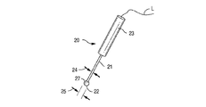
本発明の一態様では、電気刺激システムは予め定められた電気パルスを感知し、制御し、標的神経に送達する複数のデバイスを含む。一般に、図1で概略システム10として参照されたシステムは、電極の組(陰極20及び陽極28)、パルス発生器30、ユーザーインターフェース40、患者モニタリングシステム50、コントローラ60、及び絶縁パワーシステム70を含み得る。実験規模のシステムが図示及び説明されているが、より小型のユニットを使用し、望ましい電気刺激を送達することができると想定されている。
Stimulation System In one aspect of the invention, an electrical stimulation system comprises a plurality of devices that sense, control, and deliver a predetermined electrical pulse to a target nerve. Generally, the system referred to as
刺激電極
図2Aを参照すると、陰極20と呼ばれる刺激電極の全体的な形状は、オペレータが標的神経の近傍に陰極ヘッド22を正確に配置できるようなものである。本発明の一態様では、陰極20は、一方の端にヘッド22を有する細長いシャフト21と、反対側の端にハンドル23などの支持体とを含む。説明したように、陰極ヘッド22は、とがっていない形状を有する。ヘッド22から少なくとも約2.54cm(約1インチ)の距離にわたるシャフトの直径24は、ヘッドの直径25未満、またはヘッドの直径25に等しい。電気リードLは、陰極20と一体化されても、または従来の電気コネクタを使用して取り付けられても良い。このような基準を満たす可能性のある陰極の1つは、ニューヨーク州所在のAxon Systems, Inc.社から販売されている、ペディクルスクリュープローブ(pedicle screw probe)であるPSP−1000モデル(商標)である。
Stimulation Electrode With reference to FIG. 2A, the overall shape of the stimulation electrode, called the
一般に、陰極ヘッド22は、略一様な皮膚接触面を有する。すなわち、皮膚接触面は、電極から流れる電流を不必要に集中させ、皮膚を貫通さえし得る突起、鋭い縁、先端または特徴を避けるべきである。
Generally, the
望ましくは、各陰極ヘッド22の皮膚接触面は、約1.5mm2〜約40mm2の面積を有する。望ましくは、皮膚接触面27は約3.5mm2〜約20mm2の面積を有する。
Desirably, the skin contact surface of each
陰極ヘッド22は、卵円形状、楕円形状または円形状の断面を有し得る。望ましくは、陰極20のヘッド22は円形状であり、直径が約2.5mm〜約7mm、または約2.5mm〜約5mmであり得る。または、最も望ましくは直径2.5mmである。
The
本発明の一態様では、陰極20のヘッド22は球形を有し、直径が約7mm未満、または5mm未満である。最も望ましくは、直径2.5mm未満である。これらの大きさは、ヘッド22が標的神経に隣接する、望ましい筋肉の間に適合することができるような大きさである。
In one aspect of the invention, the
大きすぎるヘッド22は、標的神経に隣接した筋肉の間に適合しないだけでなく、比較的小さいヘッド22(上記のように「小さい」)と比べて低い電流密度を有する。電流密度が望ましい横隔膜応答を得るためには低すぎる場合、より多くの電力が電極に送達されなければならず、それにより不快になる可能性が増大する。更に、小さなヘッド22は、皮膚の痛覚受容体を活性化する可能性が低く、より制御可能であるので、近くの興奮性組織を共活性化することなく標的神経上にプローブを配置することが容易である。
A
図2Aは、シャフト21から延在する例示的な陰極ヘッド22の図である。ヘッド22は、略球形の形状を有し、略一様な皮膚接触面27を提供する。図2Bは、シャフト21から延在する別の例示的なヘッド22の図である。ここで、ヘッド22は、略回転楕円形状(例えば、偏球形状)を有し、略一様な皮膚接触面27を提供する。図2Cは、シャフト21から延在する更に別の例示的なヘッド22の図である。ヘッド22は、略半球形の形状を有し、略一様な皮膚接触面27を提供する。図2Dは、シャフト21から延在する更に別の例示的なヘッド22の図である。ここで、ヘッド22は、略半回転楕円体の形状(例えば、偏球の約半分)を有し、略一様な皮膚接触面27を提供する。当然のことながら、電極から流れる電流を不必要に集中させ、皮膚を貫通し得る突起、鋭い縁、先端または特徴を皮膚接触面が避けるならば、様々な他の形状及び構成を利用し得ることは想定されている。
FIG. 2A is a diagram of an
本発明の一態様では、シャフト21は、TEFLON(登録商標)フッ素重合体または他の絶縁材料でコーティングされ、電流の送達及び電極のインピーダンスをより制御しやすくする。比較的小さい陰極ヘッド22は、約12.5mA/cm2〜約9.5mA/cm2の比較的大きい電流密度に対応する。最も望ましくは、3.5mA/cm2である。陰極ヘッド22の露出面積が減少するにつれて、より小さい電力が陰極に送達されない限り、電流密度は増加する。
In one aspect of the invention, the
本発明の一態様では、ヘッド22は、ステンレススチールなどの生体適合性のある金属を含む。ハンドル23は、十分な大きさで臨床医が快適に握ることができ、偶発的な衝撃のリスクを最小限に抑える材料(例えば、プラスチック)で作られている。
In one aspect of the invention, the
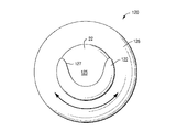
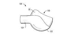
本発明の一様態では、シュラウドデバイス120を使用してヘッド22を部分的に覆い、ユーザーが標的神経に向かってより効果的に電流を導くことを可能にする。図13及び図14を参照すると、シュラウドデバイス120は、ヘッド22を部分的に覆うフード122と、ヘッド22から延在するシャフト21を完全に覆うネック124とを含む。フード122は、陰極を電気的に絶縁し、電流がフード122を越えてヘッド22から伝わることを防ぐ。
In the uniform of the present invention, the
フード122は、ヘッド22の約3分の1〜約2分の1を包み込み、ヘッド22の導電性の表面27に密接に嵌合するよう、カップ形状である。望ましくは、上面125(図14参照)が部分的に露出し、ユーザーがシャフト21を患者の身体に当て、ヘッド22を標的神経に向ける必要がないことである。
The
フード122は、TEFLON(登録商標)コーティング金属または他の非導電性材料などの絶縁材料から作ることができる。フード122は、固定されている(場合によってはコーティング材として取り付けられる)、または回転可能である。回転可能なフード122及びネック124は、更に回転中にヘッド22の周囲に緊密に嵌合し、ヘッド22及びフード122の間、並びにシャフト21及びネック124の間に無視してよい量の摩擦を受ける。望ましくは、フード122の縁部127は平滑であって、ヘッド22を皮膚に押し付けたときに患者に不快感を引き起こさない。
The
本発明の別の態様では、ショルダー126を使用して、ヘッド22の周囲でフード122を回転させる都合の良い方法をユーザーに提供することができる。図13を参照すると、1つの例示的なショルダー126は、フード122から離れた方向に延在するトランク128を含む円錐台形状を有し得る。ショルダー126とトランク128との間の接続部は、滑らかであり、図示のように鋭い縁であってはいけない。トランク128の反対側の表面121上に、ショルダー126の中心に対してネック124が取り付けられている。
In another aspect of the invention, the
トランク128は、フード122がヘッド22の周囲を回るためのダイヤルとして使用され得る。トランク128は、数字表示器で身体に対するヘッド22の位置を表すことができる。電流は陰極から対応する陽極に流れ、標的神経はその中間に位置することが留意されたい。絶縁されたフードによって、電流はよりよい方向へ向けられる(すなわち、前方と対比して後方に)。例えば、標的神経が横隔膜神経である場合、フードを回転させ、電流を横隔膜神経へ向けることができる。フード122を約180度回転させると、エルプ点で横隔膜神経の後外側方に位置する腕神経叢が、代わりに刺激される。
The
ショルダー126は、グラウンド129によって接地され、皮膚の表面上に電流が広がることを遮断または防止する材料から作られる。
The
横隔膜神経刺激の例において、任意のショルダー126を使用することで見込まれる別の利点は、皮膚に押し付けられたときに、胸鎖乳突筋102が前斜角筋104から分離するのを助け、斜角筋の前方表面で下降する横隔膜筋へアクセスしやすくすることである(図3参照)。この概念は、他の標的神経に隣接する他の筋肉にも適用され得る。
In the example of phrenic nerve stimulation, another potential benefit of using any
シュラウド120は、非対称なヘッド22と連結して使用され得ることに留意されたい。例えば、図15には、略卵形であり、凹部130を有する、ある形状にされたヘッド22が示されている。この形は、標的神経、例えば横隔膜神経に電流を集中させるために望ましいことがある。
Note that the
本発明の別の態様では(図11を参照)、シャフト21は、ヘッド22への途中で切断され(シャフト21の小さな部分のみが残る)、保持デバイスに取り付けられ、神経刺激の処置の間、標的神経上に電極を安全に配置することができると想定されている。例えば、図11は、陰極20及び陽極28が取り付けられている(どの陰極20に対しても陽極28が1つ存在する)、保持デバイスのカラー80の一実施形態を示す。横隔膜神経刺激のために設計されたカラー80は、一対のアーム83を含むC字型の本体を有する。陽極28及び陰極20は、アーム83の端部に取り付けられている。望ましくは、各陰極20のシャフト21は、各々の長手軸に沿って略整列され、ヘッド22が相互に向かい合う。望ましくは、陰極20のヘッド22と対応する陽極28のヘッド22との間の電極間距離29は、0.5cmより大きい距離で調節可能であり維持可能であるため、各陽極28のシャフト21は、屈曲性を有する、または調節可能である。更に、陽極28は、陰極20の後端から約3cmのクラビクルの上側面に配置し得る。
In another aspect of the invention (see FIG. 11), the
アーム83の間には、各アーム83の基部を反対の電極へ接続する役割を果たす、トランク部材87が存在する。ブリッジ85は、アーム83の間にわたり、2つの電極セット間の張力を調整するために使用され、使用中にカラー80が配置場所から滑り落ちることはない。ブリッジ85は、各々の長手軸に沿って整列された、及び張力デバイス86によって相互に接続された、一対の張力ブラケット84を有する。張力デバイスは、張力ブラケット84を共に、選択的に引き出す任意の装置であってよい。
Between the
図12は、横隔膜神経の両側刺激が得られる、カラー80の配置方法を示す。一般に、陰極ヘッド22は、頚部の各々の側の横隔神経に対して配置される。図3を参照すると、横隔膜神経108がクラビクル106の上部、及び胸鎖乳突筋102と前斜角筋104との間でアクセスされ得る対象の頚部100を示している。
FIG. 12 shows a method of arranging the
本発明の別の態様では、保持デバイスは、少なくとも1つの陰極20、及び少なくとも1つの陽極28を有するストラップ86である。図10を参照されたい。前記ストラップは、例えば粘着性材料または機械的ファスナ(例えば、フック及びループシステム、クリップ、スナップ、ピンなど)などの締結部品88を有し得る。
In another aspect of the invention, the holding device is a
陽極28の1つのタイプは、陰極と同様に構成される。本発明の一態様では、実施形態に関わらず、陽極の皮膚接触面27は、陰極の皮膚接触面と同じ表面積を有する。本発明の他の態様では、陽極28は、陰極20より大きい皮膚接触面を有する。
One type of
電極の組は単極の方式、または態様で刺激を送達し得る。この単極態様では、1つ、または複数の陰極が標的神経上の皮膚上に配置され、比較的大きな表面積を有する第2の不関電極(陽極)は患者の身体の表面上に配置され、回路が完成する。あるいは、刺激は双極の方式、または態様で送達することができ、上記のシステムは更に、1つ、または複数の陽極を含み得る。刺激が双極方式または双極態様で送達されるとき、陰極は標的神経上の皮膚上に配置され、対応する陽極は標的神経上の皮膚上に配置され、各々の陰極及び陽極の間の電気エネルギーの送達を優先的に集中させる。双極態様では、陽極は陰極から十分離間して配置され、分路を避ける必要がある。各陽極の皮膚接触面は、望ましくは、対応する陰極の皮膚接触面と少なくとも同じかそれより大きい表面積を有する。 The set of electrodes can deliver the stimulus in a unipolar fashion or embodiment. In this unipolar embodiment, one or more cathodes are placed on the skin on the target nerve, and a second indifferent electrode (anode) with a relatively large surface area is placed on the surface of the patient's body. The circuit is completed. Alternatively, the stimulus can be delivered in a bipolar manner, or embodiment, and the system described above may further include one or more anodes. When the stimulus is delivered in a bipolar or bipolar manner, the cathode is placed on the skin on the target nerve and the corresponding anode is placed on the skin on the target nerve, of electrical energy between each cathode and anode. Prioritize delivery. In the bipolar embodiment, the anode should be placed well away from the cathode to avoid shunting. The skin contact surface of each anode preferably has a surface area at least equal to or greater than the skin contact surface of the corresponding cathode.
パルス発生器
図1を再び参照すると、一態様では、電極の組(陰極20及び陽極28)は、リード線によって、パルス発生器30に電気的に接続され得る。パルス発生器30は、定電流の刺激装置である。1つの例示的な刺激装置は、英国所在のDigitimer Ltd.社から販売されている、定電流のDIGITIMER DS5(商標)周辺電気刺激装置である。DIGITIMER DS5(商標)装置は双極刺激を送達する。本発明の別の態様では、パルス発生器30は、定電圧のパルス発生器であってもよい。例えば、3つのこうした発生器は、米国ロードアイランド州所在のAstro−Med, Inc.社の子会社であるGrass Technologies社から入手できる、S88X(商標)、S48(商標)、SD9(商標)などである。単極刺激も、標的神経を活性化し筋肉収縮を引き起こすが、有効性は低い。
Pulse Generator With reference to FIG. 1 again, in one aspect, the set of electrodes (
ユーザーインターフェース
ユーザーインターフェース40は、ソフトウェアを動作させるコンピュータであり、コントローラから伝わったシグナルを記録し、コントローラの出力を操作するよう設計されている。考えられるソフトウェアには、英国所在のCambridge Electronic Design社の、「SPIKE(商標)」プログラムを含む。このソフトウェアは、プログラム可能であり、電気生理学的シグナルを記録及び分析することができ、刺激を可能にするようコントローラに指示することができる。
User Interface The
横隔膜神経刺激のために使用される患者モニタリングシステム
患者モニタリングシステム50は、生理学的シグナルを集め、増幅し、フィルタリングし、コントローラ60へ出力する。取得された測定結果は、(1)心拍51、(2)筋活動52、及び(3)呼吸53、を含む。心臓及び横隔膜筋からの心電図及び筋電図シグナルはそれぞれ、表面電極によって記録される。呼吸は、患者の胸部の周囲に巻かれたひずみゲージ呼吸ベルト変換機によって機械的に測定され得る。患者モニタリングシステムで得られたあらゆる生理学的シグナルは、交流シグナル増幅器/調節器(54A、54B、54C)を通過する。増幅器/調節器の一例は、米国ロードアイランド州ウェストワーウィック所在の、Astro−Med, Inc.社の子会社であるGrass Technologies社から販売されているModel LP511(商標)交流増幅器である。横隔膜筋などから記録された筋電活動がコントローラと組み合わせられることで、デバイスが較正及び刺激パラダイムを最適化でき、並びに、有効性及び特異性を医療提供者に示すことができるようになる。
Patient Monitoring System Used for Phrenic Nerve Stimulation The
コントローラ
コントローラ60は、シグナル増幅器/調節器50から電気生理学的波形データを取得することでデータ取得機能を実行し、パルス発生器30のリアルタイム制御のための電気シグナルを出力する。コントローラ60は、オンボードメモリを有し、高速データキャプチャ、独立波形サンプルレート、及びオンライン分析を容易にし得る。一態様では、コントローラ60は、英国所在の、Cambridge Electronic Design社から販売されている、POWER 1401(商標)データ取得インターフェースユニットであってもよい。
Controller The
絶縁パワーシステム
あらゆる機器は、絶縁されたパワーサプライまたはシステム70によって給電され、接地不良、及び主電源によって伝えられたパワースパイクから保護される。例示的な絶縁パワーシステムは、米国ロードアイランド州ウェストワーウィック所在の、Astro−Med, Inc.社の子会社であるGrass Technologies社製の、Model IPS115 Isolated Medical−grade Power System(商標)である。
Insulated Power System All equipment is powered by an isolated power supply or
特定の操作理論に制限されないが、一般的な皮膚接触刺激電極より実質的に小さい皮膚表面上に刺激電極を使用することによって、特に搬送周波数が使用される場合には、神経または神経線維を刺激するために必要な電流量が減少し得るということが、一般的に信じられている。少なくとも、電流密度が集中し、痛みの感覚が発生することを避けるため、電流量は最小限に抑えることができる。十分な電流密度を有し、比較的低い電流密度で神経刺激を提供することにより、痛みの感覚は防がれる。 Stimulating nerves or nerve fibers by using stimulating electrodes on skin surfaces that are substantially smaller than common skin contact stimulating electrodes, but not limited to specific operating theories, especially when carrier frequencies are used. It is generally believed that the amount of current required to do this can be reduced. At the very least, the amount of current can be minimized to avoid concentration of current density and the occurrence of pain sensations. By having sufficient current densities and providing nerve stimulation at a relatively low current density, the sensation of pain is prevented.
搬送周波数によって、皮膚を介するより、よいエネルギー送達が可能になるため、変調刺激は下側にある神経により容易に影響を与えることができる。米国食品医薬品局は、経皮的刺激のためのパワー計算が、500Ωの皮膚インピーダンスを使用することを奨励している。研究によると、搬送周波数を1MHzまで使用すると、皮膚インピーダンスが100Ωまで下がることが明らかになっている。したがって、本発明が約2.5mm(面積0.05cm2またはA)の直径を有する電極を使用し、25kHz(DC;矩形波)及び10mA(電流ピーク値(Ipeak))で電流刺激を送達する場合、同じ電流(140mA/cm2)を神経に送達するために使用される出力密度(PD;式1)は、5分の1に減少する。同じ電流密度が神経に印加された場合、搬送周波数の印加は減少し、結果として500mW/cm2〜100mW/cm2の出力密度まで減少し得る。 Modulated stimuli can more easily affect the underlying nerves because the carrier frequency allows for better energy delivery than through the skin. The US Food and Drug Administration encourages the use of 500Ω skin impedance for power calculations for percutaneous irritation. Studies have shown that when the carrier frequency is used up to 1 MHz, the skin impedance drops to 100 Ω. Therefore, the present invention uses electrodes with a diameter of about 2.5 mm (area 0.05 cm 2 or A) to deliver current stimuli at 25 kHz (DC; square wave) and 10 mA (current peak value (Ipeak)). If so, the output density (PD; Equation 1) used to deliver the same current (140 mA / cm 2) to the nerve is reduced by a factor of five. If the same current density is applied to the nerve, the application of the carrier frequency is reduced, it may be reduced to a power density of 500mW / cm 2 ~100mW / cm 2 as a result.
式1:PD=((電流実行値)1/2×(抵抗値Ω))/(電流A)
式2:電流実行値=Ipeak(DC)1/2
Equation 1: PD = ((current execution value) 1/2 x (resistance value Ω)) / (current A)
Equation 2: Current execution value = Ipeak (DC) 1/2
本発明は、電気刺激処置のためのキットも包含する。図8は、任意の様式の適当な入れ物202を含むキット200を示し、図1〜図2E、及び、場合により図10〜図15に示された構成要素の、任意の組合せが提供される。キット200は、図1に示される物品のすべてを含む必要はないことを理解されたい。すなわち、コントローラ、パルス発生器、ユーザーインターフェース、患者モニタリングシステム増幅器などの構成要素を含める必要はない。
The present invention also includes a kit for electrical stimulation treatment. FIG. 8 shows a
入れ物202は、例えば、物品が入った、取り外し可能で密封されたカバーを有する適切なトレイであってもよい。例えば、キット200の実施形態は、1つ、または複数の陰極20、及び上記のような電気リード「L」を含む入れ物202を含み得る。前記キットは更に、1つ、または複数の陽極28(図示されていない)を含み得る。
The
キット200の他の実施形態は、心電図電極55、筋電図電極56、及び圧電ベルト変換機57、並びにドレープ、ドレッシング材、テープ、スキンマーカーなどの任意の組合せなどの、図示されていない追加のアイテムを含み得る。キット200は、導電性の液体またはゲル、消毒剤、または皮膚前処理剤の、1つ、または複数の容器204を含み得る。キット200は、導電性の液体またはゲル状のワイプ、並びに殺菌用ワイプまたは皮膚前処理用ワイプ等の、前もってパッケージ化されたワイプ206を含み得る。
Other embodiments of the
横隔膜神経刺激のための電気神経パラメータ
・(1)刺激タイプ:定電流、または定電圧の矩形波パルス。
・(2)波形:単相または二相。
・(3)パルス持続時間:約100μ秒〜約250μ秒未満、もしくは約100μ秒〜約150μ秒未満であり得る。また、最も望ましくは、100μ秒である。
・(4)位相持続時間:(二相性パルスの場合のみ)パルスの各部分について、約50μ秒〜約125μ秒、または約50μ秒〜約75μ秒未満であり得る。また、最も望ましくは、50μ秒である。
・(5)電流:約0.1mA〜20mAであり得る。最も望ましいのは、3mA〜4mA(人が非常に肥満体の場合は最大5mA)の範囲である。
・(6)電流密度:(半球状で、直径2.5mmの電極ヘッドの単位面積(cm2)あたりの電流量(mA))は、約12.5mA/cm2〜約9.5mA/cm2であり得る。最も望ましくは、3.5mA/cm2である。
・(7)パルス間隔:(パルス間の時間)は、約66.5μ秒未満、または21.95μ未満であり得る。インターパルス間隔によって、筋肉収縮を誘起するときなどの筋組織の物理的変化が可能になる。
・(8)パルス周期:(1つのパルスの開始から次のパルスの開始までの時間の長さ、すなわち、位相持続時間、イントラパルス間隔、及びインターパルス間隔を含む)は、約66ミリ秒未満、または約44ミリ秒未満であり得る。また最も望ましくは約22ミリ秒である。パルス周期は、周波数に反比例する。
・(9)パルス周波数:約1Hz〜45Hz、または約20Hz〜35Hz、また最も望ましくは、約25Hzであり得る。少なくとも20Hzの周波数は、融合横隔膜応答をもたらす。
・(10)搬送シグナル:電気的刺激は、任意の搬送シグナルに重ね合わせることができる。搬送シグナルは、刺激中に皮膚のインピーダンスを低下させるために使用されることができ、神経を活性化するために上記の変調周波数によって必要とされる電流量を減少させ得る。搬送シグナルは、振幅変調方式で送達され得る。搬送シグナルは、正弦波または矩形波の形であって良く、1,000Hz〜1,000,000Hz(すなわち1MHz)の間で送達され得る。刺激システムは、システムの始動または較正中に最適な搬送シグナルを決定することもできる。
・(11)パルス列:単一パルス及びマルチパルスが送達され得る。単一パルスは始動時または較正時に使用され、刺激の有効性及び安全性を決定する。マルチパルスの列は、約1秒間、または必要に応じて送達され得る。各パルス列は、インターバースト間隔であるオフタイムによって分離されている。パルス列の持続時間は、吸気の持続時間を決定し、対象者間及び対象者内で調節可能である。パルス列は、穏やかな吸気及び呼気への移行を可能にする。呼気は受動性である。
・(12)インターバースト間隔:(各パルス列間のオフタイム)は調節可能であり、患者によって決まる。
・(13)パルスランプ:各パルスの強度が段階的に増加、または減少するときに発生する。望ましくは、ランプは、横隔膜筋の収縮を誘起するために必要とされるより少ないパルス強度ペデスタルで始まる。最終的に、強度が増加するにつれ、横隔膜神経の運動閾値が交差し、横隔膜筋は生理学的方式で収縮し始める。意図された収縮が生じた後、呼吸サイクルが完了するまで、各後続パルスの強度は段階的に減少する。パルスランプは、機能性と快適性を配慮して設計される。
Electrical nerve parameters for phrenic nerve stimulation- (1) Stimulation type: constant current or constant voltage square wave pulse.
-(2) Waveform: single-phase or two-phase.
(3) Pulse duration: can be from about 100 μs to less than about 250 μs, or from about 100 μs to less than about 150 μs. Also, most preferably, it is 100 μs.
(4) Phase duration: (only for biphasic pulses) for each portion of the pulse can be from about 50 μs to about 125 μs, or from about 50 μs to less than about 75 μs. Also, most preferably, it is 50 μsec.
(5) Current: Can be about 0.1 mA to 20 mA. Most desirable is in the range of 3 mA to 4 mA (up to 5 mA if the person is very obese).
(6) Current density: (Hemispherical, 2.5 mm diameter electrode head current amount (mA) per unit area (cm 2 )) is about 12.5 mA / cm 2 to about 9.5 mA / cm. Can be 2. Most preferably, it is 3.5 mA / cm 2 .
(7) Pulse interval: (time between pulses) can be less than about 66.5 μsec, or less than 21.95 μ. Interpulse intervals allow physical changes in muscle tissue, such as when inducing muscle contraction.
(8) Pulse period: (the length of time from the start of one pulse to the start of the next pulse, that is, including the phase duration, intrapulse interval, and interpulse interval) is less than about 66 ms. , Or less than about 44 milliseconds. Most preferably, it is about 22 milliseconds. The pulse period is inversely proportional to the frequency.
(9) Pulse frequency: may be about 1 Hz to 45 Hz, or about 20 Hz to 35 Hz, and most preferably about 25 Hz. Frequencies of at least 20 Hz result in a fused diaphragm response.
(10) Transport signal: The electrical stimulus can be superimposed on any transport signal. The carrier signal can be used to reduce the impedance of the skin during stimulation and can reduce the amount of current required by the modulation frequencies described above to activate nerves. The carrier signal can be delivered in an amplitude modulation scheme. The carrier signal may be in the form of a sinusoidal or square wave and may be delivered between 1,000 Hz and 1,000,000 Hz (
(11) Pulse train: Single pulse and multi-pulse can be delivered. A single pulse is used at start-up or during calibration to determine the efficacy and safety of the stimulus. The multi-pulse sequence can be delivered for about 1 second, or as needed. Each pulse train is separated by an off-time, which is an interburst interval. The duration of the pulse train determines the duration of inspiration and is adjustable between and within subjects. The pulse train allows a transition to gentle inspiration and expiration. Exhalation is passive.
(12) Interburst interval: (off time between each pulse train) is adjustable and patient dependent.
(13) Pulse lamp: Occurs when the intensity of each pulse gradually increases or decreases. Desirably, the ramp begins with a less pulsed intensity pedestal required to induce contraction of the diaphragmatic muscles. Eventually, as the intensity increases, the movement thresholds of the phrenic nerve intersect and the diaphragm muscles begin to contract in a physiological manner. After the intended contraction occurs, the intensity of each subsequent pulse is gradually reduced until the respiratory cycle is complete. Pulse lamps are designed with functionality and comfort in mind.
舌下神経刺激及び迷走神経刺激のための電気刺激パラメータ
舌下神経刺激及び迷走神経刺激のためのパラメータは、横隔膜神経刺激のパラメータと同じである。
Electrical stimulation parameters for hypoglossal nerve stimulation and vagal nerve stimulation The parameters for hypoglossal nerve stimulation and vagal nerve stimulation are the same as those for diaphragmatic nerve stimulation.
電気刺激の方法
本発明はまた、無傷皮膚を介して電気刺激を送達し、下側に存在する標的神経を刺激する方法を含む。この方法は、以下のステップを含む。(1)標的神経の位置を見つけるステップ。(2)各陰極が、約3.5mm2〜約40mm2の面積を有する略一様な皮膚表面を有し、標的神経の上側の皮膚上に各々が対応する陽極を有する、1つ、または複数の陰極を配置するステップ。(3)これらの電極を利用し、痛みの感覚を引き起こすことなく、また補助構造(すなわち、筋肉、非標的神経)を活性化することなく、陰極の下側に存在する標的神経を刺激して電気刺激を送達するステップ。
Methods of Electrical Stimulation The present invention also includes methods of delivering electrical stimulation through intact skin to stimulate underlying target nerves. This method involves the following steps: (1) Step to find the position of the target nerve. (2) One or one, each cathode having a substantially uniform skin surface with an area of about 3.5 mm 2 to about 40 mm 2 and each having a corresponding anode on the skin above the target nerve. The step of placing multiple cathodes. (3) Utilizing these electrodes, the target nerves located under the cathode are stimulated without causing a sensation of pain and without activating auxiliary structures (that is, muscles and non-target nerves). The step of delivering electrical stimulation.
皮膚の表面と標的神経との間隔は、約数mmである。軽度の圧力を刺激電極へ印加することで、電極―皮膚間の距離を減少させ、効果的な刺激強度を低下させ、対象の快適性を改善することができる。 The distance between the surface of the skin and the target nerve is about several mm. By applying a mild pressure to the stimulation electrode, the distance between the electrode and the skin can be reduced, the effective stimulation intensity can be reduced, and the comfort of the subject can be improved.
この方法は更に、陽極を皮膚上に、対応する陰極ごとに1つ配置することを含む。望ましくは、陽極は対応する陰極から、分路を避けるのに十分な距離を離間して、標的神経上の皮膚上に配置される。 The method further comprises placing one anode on the skin, one for each corresponding cathode. Desirably, the anode is placed on the skin on the target nerve at a distance sufficient distance from the corresponding cathode to avoid shunting.
一般に、電流制御刺激の使用は、刺激電流密度がよりよく制御されるため、電圧制御刺激より有利である。 In general, the use of current controlled stimuli is advantageous over voltage controlled stimuli because the stimulus current density is better controlled.
本発明の実施方法は、更に、導電性のゲル、液体、またはペーストなどの結合媒体の使用を含み、これを皮膚に適用し、皮膚の導電性を高め、及び/または、より低いインピーダンスにすることができる。導電性ペーストの例は、コロラド州オーロラ所在の、Weaver and Company社製の、Ten20(商標)導電性ペースト、及び、カリフォルニア州フットヒルランチに事務所を有する、日本光電工業株式会社製の、ELEFIX Conductive Paste(登録商標)を含む。導電性ゲルの例は、ニュージャージー州フェアフィールド所在の、Parker Laboratories, Inc.社製の、Spectra 360 Electrode Gel(商標)、または、オハイオ州イートン所在の、Electro−Cap International, Inc.社製の、Electro−Gel(商標)を含む。 The method of practice of the present invention further comprises the use of a binding medium such as a conductive gel, liquid, or paste, which is applied to the skin to increase the conductivity of the skin and / or to lower impedance. be able to. Examples of conductive pastes are Ten20 ™ conductive paste manufactured by Waver and Company, located in Aurora, Colorado, and ELEFIX, manufactured by Nihon Kohden Co., Ltd., which has an office in Foothill Ranch, California. Includes Colorado Paste®. Examples of conductive gels are from Parker Laboratories, Inc., located in Fairfield, NJ. Spectra 360 Electrode Gel ™, manufactured by, or Electro-Cap International, Inc., located in Eaton, Ohio. Includes Electro-Gel ™, manufactured by the company.
横隔膜神経
ほとんどの場合、有効性を最大化するために、両側神経刺激を提供することが望ましい。しかし、対応する横隔膜神経を介して、1つの片側横隔膜を刺激することは可能である。1つの肺、または神経が外科的除去、虚脱、または損傷などによって機能しない場合、片側神経刺激が望ましい。
Phrenic nerve In most cases, it is desirable to provide bilateral nerve stimulation to maximize efficacy. However, it is possible to stimulate one unilateral diaphragm via the corresponding phrenic nerve. Unilateral nerve stimulation is desirable if one lung, or nerve, does not function due to surgical removal, collapse, or injury.
両側横隔膜神経刺激の手順
・(1)安定した患者用ベッドの近くに刺激システムを設置する。
・(2)患者を快適な背臥位に置く。
・(3)患者に心電図、筋電図、及び圧電ベルト変換機を配置する。
・(4)呼吸、心拍、及び横隔膜筋電図シグナルのモニタリングを開始する。
・(5)患者の頚部の両側にある、胸鎖乳突筋の後部境界の位置を見つける。
・(6)皮膚に印をつけ、刺激電極の配置の望ましい場所を示すことが、最も望ましい。
・(7)各々の望ましい位置について、その上に陰極のヘッドを配置し、軽度の圧力を印加して陰極と横隔膜神経との間の距離を減少させる。この位置に、刺激電極を維持する。
・(8)各電極について、陽極を鎖骨の上面に、尾側に陰極を配置する。電気刺激の単一パルスを左右の刺激部位に送達し、視覚的結果、及び筋電図の結果を用いて、刺激誘発性の横隔膜筋収縮を検証する。
・(9)電気刺激パラメータを使用し、長方形のマルチパルス電気刺激を印加することで、両側の横隔膜神経が融合横隔膜収縮を達成する。電気刺激は、横隔膜神経に同時に印加されても良く、また、各片側横隔膜を交互に刺激し、各々に対してより大きな休止期間を与えても良い。
・(10)心拍変動、及び収縮期血圧を分析することにより、心血管系が安定しているかどうかを判断する。これらの尺度がベースラインから明らかに変化する場合、刺激を終了する。
Procedure for bilateral phrenic nerve stimulation ・ (1) Install a stimulation system near a stable patient bed.
・ (2) Place the patient in a comfortable supine position.
(3) Place an electrocardiogram, electromyogram, and piezoelectric belt converter in the patient.
-(4) Start monitoring breathing, heartbeat, and diaphragm EMG signals.
(5) Find the location of the posterior border of the sternocleidomastoid muscle on both sides of the patient's neck.
(6) It is most desirable to mark the skin to indicate the desired location of the stimulation electrodes.
(7) For each desired position, place a cathode head above it and apply light pressure to reduce the distance between the cathode and the phrenic nerve. The stimulation electrode is maintained in this position.
(8) For each electrode, place the anode on the upper surface of the clavicle and the cathode on the caudal side. A single pulse of electrical stimulation is delivered to the left and right stimulation sites, and visual and electromyographic results are used to verify stimulation-induced diaphragmatic muscle contraction.
(9) By applying a rectangular multi-pulse electrical stimulation using the electrical stimulation parameters, the phrenic nerves on both sides achieve fused diaphragmatic contraction. Electrical stimulation may be applied simultaneously to the phrenic nerve, or each unilateral diaphragm may be alternately stimulated, giving each one a greater rest period.
(10) Determine whether the cardiovascular system is stable by analyzing heart rate variability and systolic blood pressure. If these measures clearly change from baseline, the stimulus is terminated.
迷走神経刺激の手順
迷走神経刺激は、原発性頭痛、片頭痛、喘息、運動誘発性気管支痙攣、及びCOPDの急性緩和を引き起こし得る。更に、片頭痛及び群発頭痛に対する予防処置に使用することができる。上記の横隔膜神経刺激パラダイムの若干の変更のみが、迷走神経の刺激に必要である。迷走神経200を刺激するために、電極の組は首の皮膚領域202上、及び下顎の下部に配置される(図16)。具体的には、陰極20は、胸鎖乳突筋と気管との間に配置される。自律活動(すなわち、心拍、つまり皮膚の血流変化)のマーカーは、迷走神経の活性化を示すために使用される。
Vagal Maneuver Procedures Vagal maneuver can cause primary headache, migraine, asthma, exercise-induced bronchospasm, and acute relief of COPD. In addition, it can be used as a preventative measure against migraine and cluster headaches. Only minor changes to the phrenic nerve stimulation paradigm described above are required to stimulate the vagus nerve. To stimulate the
舌下神経刺激の手順
閉塞性睡眠時無呼吸は、舌下神経、または舌下神経枝を刺激することによって治療される。本明細書に記載されているような横隔膜神経刺激パラダイムの、若干の変更のみが必要である。更に、刺激が呼吸パターンと連動するよう、センサを使用することができる。電極の組は、頚上部または下顎の部位から舌下神経(または舌下神経枝)への刺激を送達し、横隔膜筋または自律神経系によって生じる呼吸運動を感知する。刺激は、軟組織(すなわち、舌)が気道を妨害しないよう設計されている。
Hypoglossal Nerve Stimulation Procedures Obstructive sleep apnea is treated by stimulating the hypoglossal nerve, or hypoglossal nerve branch. Only minor changes to the phrenic nerve stimulation paradigm as described herein are required. In addition, sensors can be used so that the stimulus is linked to the respiratory pattern. The set of electrodes delivers stimulation to the hypoglossal nerve (or hypoglossal nerve branch) from the upper cervical or lower jaw site and senses respiratory movements produced by the diaphragmatic muscles or the autonomic nervous system. The stimulus is designed so that the soft tissue (ie, the tongue) does not interfere with the airways.
実験
21歳〜40歳の健康なボランティア15名が、電気生理学的検査を受け、表面電気刺激が、痛み、望ましくない筋肉収縮、及び生理学的方式をともなわずに、人の横隔膜筋収縮を行うことができるかどうか判定した。
Experiments Fifteen healthy volunteers between the ages of 21 and 40 undergo electrophysiological examination and surface electrical stimulation performs human diaphragmatic muscle contraction without pain, unwanted muscle contraction, and physiological methods. It was judged whether or not it could be done.
本明細書に記載の方法にしたがって、本発明の陰極を、胸鎖乳突筋の後縁に配置し、皮膚に軽く押し付けた。対応する陽極を、正中線で頚部の後面に適用した。 According to the method described herein, the cathode of the invention was placed on the trailing edge of the sternocleidomastoid muscle and lightly pressed against the skin. The corresponding anode was applied to the posterior surface of the neck at the median.
定電流パルスを、単一パルス及びマルチパルス(1秒パルス列)方式で各対象に送達した。パルス持続時間は、10mA未満の強度、50μ秒〜150μ秒の範囲で、様々な周波数(10、15、20、及び25Hz)及びランプ率であった。ランプ入力として与えられるパルス列を1秒間、及びパルス持続時間を100μ秒で送達した。上記のように、各パルスの強度を、先行するパルスの強度から僅かに(0〜0.4mA)増加させた。最初の数パルスの強度は非常に弱く、横隔膜筋収縮を誘起できなかった(運動閾値下)。 Constant current pulses were delivered to each subject in a single pulse and multi-pulse (1 second pulse train) fashion. Pulse durations ranged from less than 10 mA, 50 μs to 150 μs, at various frequencies (10, 15, 20, and 25 Hz) and ramp rates. The pulse train given as the ramp input was delivered in 1 second and the pulse duration was delivered in 100 μs. As mentioned above, the intensity of each pulse was increased slightly (0-0.4 mA) from the intensity of the preceding pulse. The intensity of the first few pulses was so weak that it was unable to induce diaphragmatic muscle contraction (below the motor threshold).
結果測定は以下を含んだ。1)横隔膜筋から記録された筋電図シグナル、2)心拍変動を測定するための心電図、3)呼吸、及び4)視覚的アナログスケール(VAS)。VAS(図9)は、知覚された痛みのレベルを測定する、一般に認められた方法である。 Results measurements included: 1) EMG signals recorded from the diaphragm muscles, 2) ECGs for measuring heart rate variability, 3) Respiration, and 4) Visual analog scales (VAS). VAS (Fig. 9) is a generally accepted method of measuring the level of perceived pain.
結果は、痛み、または望ましくない筋肉収縮を引き起こすことなく、人の横隔膜筋を活性化させる、横隔膜神経への電気刺激の単一パルス70を示した(図4)。単一パルス70は、呼吸の突然の増加(呼吸スパイク72を参照)、及び、横隔膜の突然の変化(心電図スパイク74を参照)に対応する。重要なことに、全ての被験者は、VASスコアが「0」であることを示し、同様に、刺激が自発的に生じた吃逆のように感じられたと報告した。刺激は、心拍の変化を誘起しなかった。
The results showed a
20Hzより大きい周波数でのマルチパルス電気刺激は、融合横隔膜収縮を可能にした。図6を参照すると、融合呼吸スパイク72に対応するマルチパルス70、及び、複数であるが圧縮された横隔膜スパイク74を示している。
Multi-pulse electrical stimulation at frequencies above 20 Hz allowed fusion diaphragm contraction. Referring to FIG. 6, the multi-pulse 70 corresponding to the
ランプ入力として与えられるマルチパルス刺激は、徐々に増加する横隔膜筋収縮、及び、穏やかな吸気を引き起こす。図7を参照すると、電流が経時的に増加するマルチパルス70(20Hzにおいて)を示している。融合スパイク74はまた、ランプ入力として与えられた形状を有する。更に、被験者は、VASの痛みレベル0を報告し、本発明の方法が、痛覚受容体を動員することなく生理学的な横隔膜筋収縮を誘起したことを示した。
Multi-pulse stimulation given as a ramp input causes gradually increasing diaphragmatic muscle contraction and gentle inspiration. Referring to FIG. 7, a multi-pulse 70 (at 20 Hz) in which the current increases over time is shown. The
本発明は特定の実施形態に関して詳細に開示してきたが、当業者が上述の内容を理解すれば、これらの実施形態の代替形態、改変、及び均等物を容易に想到し得ることは理解されよう。したがって、本発明の範囲は特許請求の範囲及び、特許請求の範囲に対するあらゆる均等物として評価されるべきである。 Although the present invention has been disclosed in detail with respect to specific embodiments, it will be appreciated that one of ordinary skill in the art can easily conceive of alternatives, modifications, and equivalents of these embodiments. .. Therefore, the scope of the present invention should be evaluated as the scope of claims and any equivalent to the scope of claims.
Claims (15)
保持デバイスと、
前記保持デバイスに取り付けられた陰極と陽極とを含む電極の組であって、前記陰極は、約1.5mm2〜約40mm2の面積を有する略一様な陰極皮膚接触面を画定し、前記陽極は、前記陰極皮膚接触面と同一またはそれより大きい面積を有する陽極皮膚接触面を有し、前記陰極及び前記陽極はシャフトを含み、前記陰極及び前記陽極の少なくとも一方の前記シャフトが屈曲性を有することにより前記陰極と前記陽極との間の電極間距離が調節可能である、該電極の組と、
前記電極の組に電気的に接続された電子制御システムとを含み、
前記電子制御システムは、前記電極の組を介して、前記陰極の下側に存在する前記標的神経に電気刺激を送達して前記筋肉収縮を引き起こし、
前記電気神経刺激が、約0.1mA〜約20mAの定電流を有し、
前記電気神経刺激が、約1Hz〜約45Hzの範囲の周波数で印加されることを特徴とするシステム。 A system for delivering electrical nerve stimulation through the mammalian intact skin to stimulate target nerves beneath the mammalian intact skin to cause muscle contraction.
Retention device and
A set of electrodes including a cathode and an anode attached to the holding device, wherein the cathode defines a substantially uniform cathode skin contact surface having an area of about 1.5 mm 2 to about 40 mm 2. the anode has the cathode skin contacting surface of the same or anode skin contacting surface having a larger area that the includes a cathode and the anode shaft, at least one of the shaft of the cathode and the anode is flexible With the set of electrodes, the distance between the electrodes between the cathode and the anode can be adjusted by having the cathode.
Including an electronic control system electrically connected to the set of electrodes.
The electronic control system, via a set of electrodes, the target nerve to deliver electrical stimulation to provoked the muscle contraction that exist below the cathode,
The electrical nerve stimulation has a constant current of about 0.1 mA to about 20 mA and
A system characterized in that the electrical nerve stimulation is applied at a frequency in the range of about 1 Hz to about 45 Hz.
前記哺乳動物の生理学的機能をモニタリングするための構成要素を更に含み、前記電気神経刺激の送達が、前記生理学的機能と連動することを特徴とするシステム。 The system according to claim 1.
A system further comprising a component for monitoring the physiological function of the mammal, wherein the delivery of the electroneuronial stimulus is linked to the physiological function.
前記生理学的機能が、呼吸サイクルであることを特徴とするシステム。 The system according to claim 2.
A system characterized in that the physiological function is a respiratory cycle.
前記電気神経刺激が、約1kHz〜約1MHzの範囲の搬送周波数を更に含むことを特徴とするシステム。 The system according to claim 1.
A system characterized in that the electrical nerve stimulation further comprises a carrier frequency in the range of about 1 kHz to about 1 MHz.
前記電気神経刺激が、矩形波パルスと、振幅及び周波数が変化するパルス列とを有する電流であることを特徴とするシステム。 The system according to claim 1.
A system characterized in that the electrical nerve stimulation is a current having a square wave pulse and a pulse train whose amplitude and frequency change.
前記矩形波パルスが、約250μ秒未満のパルス持続時間を有することを特徴とするシステム。 The system according to claim 5.
A system characterized in that the square wave pulse has a pulse duration of less than about 250 μsec.
前記パルス列がランプ入力として与えられることを特徴とするシステム。 The system according to claim 5.
A system characterized in that the pulse train is given as a ramp input.
前記標的神経が、横隔膜神経、迷走神経、または舌下神経であることを特徴とするシステム。 The system according to any one of claims 1 to 7.
A system characterized in that the target nerve is a phrenic nerve, a vagus nerve, or a hypoglossal nerve.
前記標的神経が前記横隔膜神経であり、人工呼吸器からの前記哺乳動物の離脱を容易化するために、前記横隔膜神経の前記電気神経刺激が、前記哺乳動物の横隔膜筋を強化することを特徴とするシステム。 The system according to claim 8.
The target nerve is the phrenic nerve, and the electrical nerve stimulation of the phrenic nerve strengthens the diaphragm muscle of the mammal in order to facilitate the withdrawal of the mammal from the ventilator. System to do.
前記陰極の略一様な前記陰極皮膚接触面が、半球形状、略半球形状、または楕円体形状であることを特徴とするシステム。 The system according to any one of claims 1 to 9.
A system characterized in that the substantially uniform cathode skin contact surface of the cathode has a hemispherical shape, a substantially hemispherical shape, or an ellipsoidal shape.
前記陰極皮膚接触面が、約3.5mm 2 〜約20mm 2 の面積を有することを特徴とするシステム。 The system according to any one of claims 1 to 10.
A system characterized in that the cathode skin contact surface has an area of about 3.5 mm 2 to about 20 mm 2.
前記陰極は、ヘッドを含み、
前記ヘッドが、シュラウドデバイスのフードによって部分的に覆われ、
前記陰極の前記シャフトが、シュラウドデバイスのネックによって部分的に覆われることを特徴とするシステム。 The system according to any one of claims 1 to 11.
The cathode comprises a head,
The head is partially covered by the hood of the shroud device.
A system characterized in that the shaft of the cathode is partially covered by the neck of a shroud device.
前記電気神経刺激が、前記標的神経へ送達されることを容易化するために、前記フードが、前記ヘッド周囲を回転するよう構成されることを特徴とするシステム。 The system according to claim 12.
A system characterized in that the hood is configured to rotate around the head to facilitate delivery of the electrical nerve stimulus to the target nerve.
前記保持デバイスは、C字型の本体を有するカラーを含み、前記陰極及び前記陽極が前記カラーの端部に取り付けられたことを特徴とするシステム。 The system according to any one of claims 1 to 13.
The holding device comprises a collar having a C-shaped body, wherein the cathode and the anode are attached to the ends of the collar.
保持デバイスと、前記保持デバイスに取り付けられた1以上の陰極と、前記保持デバイスに取り付けられた1以上の陽極と、電気リードとを含み、
前記陰極の各々は、略一様な陰極皮膚接触面を画定し、前記陰極皮膚接触面の各々は、約3.5mm2〜約40mm2の面積を有し、
前記陽極の各々は、陽極皮膚接触面を有し、前記陽極皮膚接触面の各々は、前記陰極皮膚接触面の各々と同一、またはそれより大きい面積を有し、
前記陰極及び前記陽極はシャフトを含み、前記陰極及び前記陽極の少なくとも一方の前記シャフトが屈曲性を有することにより1以上の前記陰極と1以上の前記陽極との間の電極間距離は、使用時に調節可能であり、
前記電気リードは、1以上の前記陰極を介して電気刺激を送達し、1以上の前記陰極の下側に存在する標的神経を刺激して筋肉収縮を引き起こすために、1以上の前記陰極と、1以上の前記陽極とを、電子制御システムへ接続し、
前記電気神経刺激が、約0.1mA〜約20mAの定電流を有し、
前記電気神経刺激が、約1Hz〜約45Hzの範囲の周波数で印加されることを特徴とするキット。 A kit for electrical nerve stimulation treatment
It comprises a holding device, one or more cathodes attached to the holding device, one or more anodes attached to the holding device, and electrical leads.
Each of the cathodes defines a substantially uniform cathode skin contact surface, and each of the cathode skin contact surfaces has an area of about 3.5 mm 2 to about 40 mm 2.
Each of the anodes has an anode skin contact surface, and each of the anode skin contact surfaces has an area equal to or larger than each of the cathode skin contact surfaces.
Wherein comprises a cathode and the anode shaft, the inter-electrode distance between one or more of the cathode and one or more of the anode by at least one of the shaft of the cathode and the anode has a flexibility, in use Adjustable and
The electrical leads, with one or more cathodes, to deliver electrical stimulation through one or more cathodes and to stimulate target nerves beneath the one or more cathodes to cause muscle contraction. One or more of the anodes are connected to the electronic control system,
The electrical nerve stimulation has a constant current of about 0.1 mA to about 20 mA and
A kit characterized in that the electric nerve stimulation is applied at a frequency in the range of about 1 Hz to about 45 Hz.
Applications Claiming Priority (3)
| Application Number | Priority Date | Filing Date | Title |
|---|---|---|---|
| US201462073302P | 2014-10-31 | 2014-10-31 | |
| US62/073,302 | 2014-10-31 | ||
| PCT/US2015/057710 WO2016069689A1 (en) | 2014-10-31 | 2015-10-28 | Non-invasive nerve stimulation system |
Publications (3)
| Publication Number | Publication Date |
|---|---|
| JP2017533752A JP2017533752A (en) | 2017-11-16 |
| JP2017533752A5 JP2017533752A5 (en) | 2020-01-16 |
| JP6928554B2 true JP6928554B2 (en) | 2021-09-01 |
Family
ID=54477350
Family Applications (1)
| Application Number | Title | Priority Date | Filing Date |
|---|---|---|---|
| JP2017522973A Active JP6928554B2 (en) | 2014-10-31 | 2015-10-28 | Non-invasive nerve stimulation system and non-invasive nerve stimulation method |
Country Status (11)
| Country | Link |
|---|---|
| US (1) | US10485971B2 (en) |
| EP (1) | EP3212277B1 (en) |
| JP (1) | JP6928554B2 (en) |
| KR (1) | KR20170078640A (en) |
| CN (1) | CN107073262B (en) |
| AU (1) | AU2015339357B2 (en) |
| BR (1) | BR112017009068A2 (en) |
| CA (1) | CA2966197C (en) |
| MX (1) | MX364500B (en) |
| RU (1) | RU2017114372A (en) |
| WO (1) | WO2016069689A1 (en) |
Families Citing this family (7)
| Publication number | Priority date | Publication date | Assignee | Title |
|---|---|---|---|---|
| CN107106839A (en) * | 2014-12-12 | 2017-08-29 | 禹大起 | Low-frequency therapeutic wearing band |
| CN105854184A (en) * | 2016-06-21 | 2016-08-17 | 江苏承康医用设备有限公司 | Noninvasive neuromuscular electrical stimulation device |
| WO2018204204A1 (en) * | 2017-05-04 | 2018-11-08 | Medipines Ccorporation | Systems and methods for stimulating a patient to prevent oxygen desaturation |
| GB2571919B (en) * | 2018-02-26 | 2021-08-18 | Goroszeniuk Teodor | Improvements in and relating to electrodes for medical stimulating devices |
| US11911615B2 (en) * | 2020-04-01 | 2024-02-27 | University Of Georgia Research Foundation, Inc. | Systems and methods for assessing respiratory function |
| CN111657940B (en) * | 2020-06-22 | 2023-04-18 | 中国人民解放军陆军特色医学中心 | Severe patient rehabilitation training auxiliary device and working method thereof |
| KR102639644B1 (en) | 2020-10-01 | 2024-02-23 | 선라이즈 에스에이 | Wearable device for reducing breathing difficulties in sleeping subjects |
Family Cites Families (36)
| Publication number | Priority date | Publication date | Assignee | Title |
|---|---|---|---|---|
| US2535788A (en) | 1949-11-26 | 1950-12-26 | David M Davidoff | Electromagnetic machine |
| US2664880A (en) | 1951-11-23 | 1954-01-05 | Jr Nathaniel B Wales | Electric stimulator for artificial respiration |
| US4827935A (en) | 1986-04-24 | 1989-05-09 | Purdue Research Foundation | Demand electroventilator |
| US5056519A (en) | 1990-05-14 | 1991-10-15 | Vince Dennis J | Unilateral diaphragmatic pacer |
| SE9201453L (en) * | 1992-05-08 | 1993-07-12 | Jens Schouenborg | MEDICAL DEVICE FOR RELIEFING THE PAIN CONDITION INCLUDING AN ELECTRIC PLATE |
| US6463327B1 (en) | 1998-06-11 | 2002-10-08 | Cprx Llc | Stimulatory device and methods to electrically stimulate the phrenic nerve |
| US6234985B1 (en) * | 1998-06-11 | 2001-05-22 | Cprx Llc | Device and method for performing cardiopulmonary resuscitation |
| SE9803508D0 (en) | 1998-10-14 | 1998-10-14 | Siemens Elema Ab | Assisted Breathing System |
| US6450942B1 (en) * | 1999-08-20 | 2002-09-17 | Cardiorest International Ltd. | Method for reducing heart loads in mammals |
| AU2001257582A1 (en) | 2000-03-14 | 2001-09-24 | Children's Medical Center Corporation, The | Method for improving respiratory function and inhibiting muscular degeneration |
| US20020077688A1 (en) * | 2000-12-15 | 2002-06-20 | Kirkland Thomas C. | Electrode-positioning body garment |
| SE0202537D0 (en) | 2002-08-28 | 2002-08-28 | Siemens Elema Ab | Nerve stimulation apparatus |
| US7277757B2 (en) | 2002-10-31 | 2007-10-02 | Medtronic, Inc. | Respiratory nerve stimulation |
| US20060111755A1 (en) | 2003-05-16 | 2006-05-25 | Stone Robert T | Method and system to control respiration by means of neuro-electrical coded signals |
| WO2005009291A2 (en) | 2003-07-23 | 2005-02-03 | Synapse Biomedical, Inc. | System and method for conditioning a diaphragm of a patient |
| US8467876B2 (en) | 2003-10-15 | 2013-06-18 | Rmx, Llc | Breathing disorder detection and therapy delivery device and method |
| US7979128B2 (en) | 2003-10-15 | 2011-07-12 | Rmx, Llc | Device and method for gradually controlling breathing |
| US20100016929A1 (en) * | 2004-01-22 | 2010-01-21 | Arthur Prochazka | Method and system for controlled nerve ablation |
| JP4879754B2 (en) * | 2004-01-22 | 2012-02-22 | リハブトロニクス インコーポレーテッド | Method for carrying electrical current to body tissue via implanted non-active conductor |
| WO2006009771A1 (en) * | 2004-06-18 | 2006-01-26 | Neuronetrix, Inc. | Evoked response testing system for neurological disorders |
| US7613517B2 (en) | 2004-10-20 | 2009-11-03 | Teodor Goroszeniuk | Method for neurostimulation |
| US8332029B2 (en) * | 2005-06-28 | 2012-12-11 | Bioness Inc. | Implant system and method using implanted passive conductors for routing electrical current |
| US20070078372A1 (en) * | 2005-09-30 | 2007-04-05 | Vyteris, Inc. | Iontophoresis Drug Delivery Formulation Providing Acceptable Sensation and Dermal Anesthesia |
| JP4934805B2 (en) | 2005-12-02 | 2012-05-23 | 国立大学法人東北大学 | Electrical stimulator for prevention, treatment of oral, pharyngeal and laryngeal dysfunction |
| US7797046B2 (en) * | 2006-10-11 | 2010-09-14 | Cardiac Pacemakers, Inc. | Percutaneous neurostimulator for modulating cardiovascular function |
| US8175718B2 (en) | 2006-12-19 | 2012-05-08 | Ethicon, Inc. | Electrode patch and method for neurostimulation |
| WO2009134459A2 (en) * | 2008-05-02 | 2009-11-05 | The Johns Hopkins University | Portable negative pressure ventilation device and methods and software related thereto |
| JP5385582B2 (en) * | 2008-10-10 | 2014-01-08 | 大学共同利用機関法人自然科学研究機構 | Pain sensory nerve stimulator |
| US9895530B2 (en) * | 2008-12-05 | 2018-02-20 | Spr Therapeutics, Inc. | Systems and methods to place one or more leads in tissue to electrically stimulate nerves of passage to treat pain |
| CA2761530C (en) * | 2008-12-05 | 2018-09-04 | Spr Therapeutics, Llc | Systems and methods to place one or more leads in tissue for providing functional and/or therapeutic stimulation |
| US20100274329A1 (en) * | 2009-04-24 | 2010-10-28 | Chris Bradley | System and method for skin care using light and microcurrents |
| KR20170127056A (en) * | 2009-10-05 | 2017-11-20 | 더 리젠트스 오브 더 유니이버시티 오브 캘리포니아 | Extracranial implantable devices, systems and methods for the treatment of neurological disorders |
| US20150257970A1 (en) * | 2011-02-17 | 2015-09-17 | Martin Mücke | Device and method for reducing pain |
| EP2758126B1 (en) * | 2011-09-22 | 2020-01-01 | Djo, Llc | Devices and system for treating pain with electrical stimulation |
| CN107376115A (en) * | 2011-11-15 | 2017-11-24 | 神经系统检测公司 | For mitigating the apparatus and method of pain using transcutaneous electrical nerve stimulation |
| WO2014082064A1 (en) * | 2012-11-26 | 2014-05-30 | Thync, Inc. | Wearable transdermal electrical stimulation devices and methods of using them |
-
2015
- 2015-10-28 EP EP15790788.2A patent/EP3212277B1/en active Active
- 2015-10-28 JP JP2017522973A patent/JP6928554B2/en active Active
- 2015-10-28 RU RU2017114372A patent/RU2017114372A/en not_active Application Discontinuation
- 2015-10-28 BR BR112017009068A patent/BR112017009068A2/en not_active Application Discontinuation
- 2015-10-28 CN CN201580057732.7A patent/CN107073262B/en active Active
- 2015-10-28 WO PCT/US2015/057710 patent/WO2016069689A1/en active Application Filing
- 2015-10-28 CA CA2966197A patent/CA2966197C/en active Active
- 2015-10-28 AU AU2015339357A patent/AU2015339357B2/en active Active
- 2015-10-28 US US15/522,826 patent/US10485971B2/en active Active
- 2015-10-28 KR KR1020177011326A patent/KR20170078640A/en unknown
- 2015-10-28 MX MX2017004547A patent/MX364500B/en active IP Right Grant
Also Published As
| Publication number | Publication date |
|---|---|
| US20170333706A1 (en) | 2017-11-23 |
| CN107073262A (en) | 2017-08-18 |
| EP3212277B1 (en) | 2020-12-16 |
| US10485971B2 (en) | 2019-11-26 |
| MX364500B (en) | 2019-04-29 |
| BR112017009068A2 (en) | 2017-12-19 |
| AU2015339357A1 (en) | 2017-04-20 |
| CA2966197C (en) | 2023-04-11 |
| EP3212277A1 (en) | 2017-09-06 |
| MX2017004547A (en) | 2017-06-23 |
| CA2966197A1 (en) | 2016-05-06 |
| WO2016069689A1 (en) | 2016-05-06 |
| AU2015339357B2 (en) | 2019-11-21 |
| JP2017533752A (en) | 2017-11-16 |
| RU2017114372A3 (en) | 2019-03-29 |
| RU2017114372A (en) | 2018-12-03 |
| KR20170078640A (en) | 2017-07-07 |
| CN107073262B (en) | 2021-01-05 |
Similar Documents
| Publication | Publication Date | Title |
|---|---|---|
| JP6928554B2 (en) | Non-invasive nerve stimulation system and non-invasive nerve stimulation method | |
| JP6970704B2 (en) | Devices and methods for non-invasive capacitive electrical stimulation, as well as their use for vagal nerve stimulation of the patient's neck | |
| US10507325B2 (en) | Devices and methods for non-invasive capacitive electrical stimulation and their use for vagus nerve stimulation on the neck of a patient | |
| US20200078589A1 (en) | Non-invasive vagal nerve stimulation to treat disorders | |
| US20170266443A1 (en) | Method and apparatus for transdermal stimulation over the palmar and plantar surfaces | |
| US8914122B2 (en) | Devices and methods for non-invasive capacitive electrical stimulation and their use for vagus nerve stimulation on the neck of a patient | |
| US20060200219A1 (en) | Systems and methods for differentiating and/or identifying tissue regions innervated by targeted nerves for diagnostic and/or therapeutic purposes | |
| JP6891111B2 (en) | Methods and systems for monitoring or treating medical conditions via posterior tibial nerve stimulation | |
| US20220362550A1 (en) | Devices and methods for adjusting and tracking respiration-stimulating electrodes | |
| US20220347471A1 (en) | Devices and methods for non-invasive vagal nerve stimulation |
Legal Events
| Date | Code | Title | Description |
|---|---|---|---|
| A621 | Written request for application examination |
Free format text: JAPANESE INTERMEDIATE CODE: A621 Effective date: 20181022 |
|
| A131 | Notification of reasons for refusal |
Free format text: JAPANESE INTERMEDIATE CODE: A131 Effective date: 20190827 |
|
| A977 | Report on retrieval |
Free format text: JAPANESE INTERMEDIATE CODE: A971007 Effective date: 20190823 |
|
| A524 | Written submission of copy of amendment under article 19 pct |
Free format text: JAPANESE INTERMEDIATE CODE: A524 Effective date: 20191126 |
|
| A02 | Decision of refusal |
Free format text: JAPANESE INTERMEDIATE CODE: A02 Effective date: 20191224 |
|
| A521 | Request for written amendment filed |
Free format text: JAPANESE INTERMEDIATE CODE: A523 Effective date: 20200421 |
|
| C60 | Trial request (containing other claim documents, opposition documents) |
Free format text: JAPANESE INTERMEDIATE CODE: C60 Effective date: 20200421 |
|
| A911 | Transfer to examiner for re-examination before appeal (zenchi) |
Free format text: JAPANESE INTERMEDIATE CODE: A911 Effective date: 20200507 |
|
| C21 | Notice of transfer of a case for reconsideration by examiners before appeal proceedings |
Free format text: JAPANESE INTERMEDIATE CODE: C21 Effective date: 20200512 |
|
| A912 | Re-examination (zenchi) completed and case transferred to appeal board |
Free format text: JAPANESE INTERMEDIATE CODE: A912 Effective date: 20200731 |
|
| C211 | Notice of termination of reconsideration by examiners before appeal proceedings |
Free format text: JAPANESE INTERMEDIATE CODE: C211 Effective date: 20200804 |
|
| C22 | Notice of designation (change) of administrative judge |
Free format text: JAPANESE INTERMEDIATE CODE: C22 Effective date: 20201215 |
|
| C22 | Notice of designation (change) of administrative judge |
Free format text: JAPANESE INTERMEDIATE CODE: C22 Effective date: 20210202 |
|
| C13 | Notice of reasons for refusal |
Free format text: JAPANESE INTERMEDIATE CODE: C13 Effective date: 20210209 |
|
| A521 | Request for written amendment filed |
Free format text: JAPANESE INTERMEDIATE CODE: A523 Effective date: 20210507 |
|
| C23 | Notice of termination of proceedings |
Free format text: JAPANESE INTERMEDIATE CODE: C23 Effective date: 20210615 |
|
| C03 | Trial/appeal decision taken |
Free format text: JAPANESE INTERMEDIATE CODE: C03 Effective date: 20210720 |
|
| C30A | Notification sent |
Free format text: JAPANESE INTERMEDIATE CODE: C3012 Effective date: 20210720 |
|
| A61 | First payment of annual fees (during grant procedure) |
Free format text: JAPANESE INTERMEDIATE CODE: A61 Effective date: 20210806 |
|
| R150 | Certificate of patent or registration of utility model |
Ref document number: 6928554 Country of ref document: JP Free format text: JAPANESE INTERMEDIATE CODE: R150 |