JP6927706B2 - Expandable clearance panel systems, methods and assemblies for monuments in the interior cabin of the aircraft - Google Patents
Expandable clearance panel systems, methods and assemblies for monuments in the interior cabin of the aircraft Download PDFInfo
- Publication number
- JP6927706B2 JP6927706B2 JP2017008265A JP2017008265A JP6927706B2 JP 6927706 B2 JP6927706 B2 JP 6927706B2 JP 2017008265 A JP2017008265 A JP 2017008265A JP 2017008265 A JP2017008265 A JP 2017008265A JP 6927706 B2 JP6927706 B2 JP 6927706B2
- Authority
- JP
- Japan
- Prior art keywords
- monument
- panel
- force
- interior cabin
- fixed
- Prior art date
- Legal status (The legal status is an assumption and is not a legal conclusion. Google has not performed a legal analysis and makes no representation as to the accuracy of the status listed.)
- Active
Links
Images


Classifications
-
- B—PERFORMING OPERATIONS; TRANSPORTING
- B64—AIRCRAFT; AVIATION; COSMONAUTICS
- B64D—EQUIPMENT FOR FITTING IN OR TO AIRCRAFT; FLIGHT SUITS; PARACHUTES; ARRANGEMENTS OR MOUNTING OF POWER PLANTS OR PROPULSION TRANSMISSIONS IN AIRCRAFT
- B64D11/00—Passenger or crew accommodation; Flight-deck installations not otherwise provided for
- B64D11/06—Arrangements of seats, or adaptations or details specially adapted for aircraft seats
- B64D11/0606—Arrangements of seats, or adaptations or details specially adapted for aircraft seats with privacy shells, screens, separators or the like
-
- B—PERFORMING OPERATIONS; TRANSPORTING
- B64—AIRCRAFT; AVIATION; COSMONAUTICS
- B64D—EQUIPMENT FOR FITTING IN OR TO AIRCRAFT; FLIGHT SUITS; PARACHUTES; ARRANGEMENTS OR MOUNTING OF POWER PLANTS OR PROPULSION TRANSMISSIONS IN AIRCRAFT
- B64D11/00—Passenger or crew accommodation; Flight-deck installations not otherwise provided for
- B64D11/0023—Movable or removable cabin dividers, e.g. for class separation
-
- B—PERFORMING OPERATIONS; TRANSPORTING
- B64—AIRCRAFT; AVIATION; COSMONAUTICS
- B64D—EQUIPMENT FOR FITTING IN OR TO AIRCRAFT; FLIGHT SUITS; PARACHUTES; ARRANGEMENTS OR MOUNTING OF POWER PLANTS OR PROPULSION TRANSMISSIONS IN AIRCRAFT
- B64D11/00—Passenger or crew accommodation; Flight-deck installations not otherwise provided for
- B64D11/02—Toilet fittings
-
- B—PERFORMING OPERATIONS; TRANSPORTING
- B64—AIRCRAFT; AVIATION; COSMONAUTICS
- B64D—EQUIPMENT FOR FITTING IN OR TO AIRCRAFT; FLIGHT SUITS; PARACHUTES; ARRANGEMENTS OR MOUNTING OF POWER PLANTS OR PROPULSION TRANSMISSIONS IN AIRCRAFT
- B64D11/00—Passenger or crew accommodation; Flight-deck installations not otherwise provided for
- B64D11/04—Galleys
-
- B—PERFORMING OPERATIONS; TRANSPORTING
- B64—AIRCRAFT; AVIATION; COSMONAUTICS
- B64D—EQUIPMENT FOR FITTING IN OR TO AIRCRAFT; FLIGHT SUITS; PARACHUTES; ARRANGEMENTS OR MOUNTING OF POWER PLANTS OR PROPULSION TRANSMISSIONS IN AIRCRAFT
- B64D25/00—Emergency apparatus or devices, not otherwise provided for
- B64D25/02—Supports or holding means for living bodies
Description
本開示の諸実施形態は、一般に、展開可能な隙間パネルシステム(deployable clearance panel systems)、方法、および組立体、例えば、航空機の内部客室内のモニュメント(monument)の一部に関する。 The embodiments of the present disclosure generally relate to deployable clearance panel systems, methods, and assemblies, such as parts of monuments in the interior cabin of an aircraft.
民間航空機は、通常、内部客室内の適所にしっかりと固定された多くの座席列を含む。内部客室内にはファーストクラスセクション、ビジネスクラスセクション、およびエコノミークラスセクションがあり得る。航空機の各セクションは互いに離間された座席列を有することができる。 Commercial aircraft usually include many rows of seats that are firmly fixed in place in the interior cabin. There may be a first class section, a business class section, and an economy class section in the interior cabin. Each section of the aircraft can have rows of seats separated from each other.
航空機の内部客室は、1つまたは複数のモニュメント、例えば、洗面所、調理室、クロゼット、仕切り、および/または同類のものも含むことができる。様々なモニュメントが座席列の前に配置される後方壁を含む。米国連邦航空局(「FAA」)は、航空機の内部客室内の座席とモニュメントの後方壁との間の最小距離を義務付けている。例えば、FAAは、頭部衝突ゾーン(head strike zone)を座席基準点から半径35インチ(86cm)以内の領域と定義している。したがって、後方モニュメント壁は、座席基準点から35インチの直線水平距離を超える距離を隔てて設置される。 The interior cabin of an aircraft can also include one or more monuments, such as washrooms, kitchens, closets, dividers, and / or the like. Includes a rear wall where various monuments are placed in front of the row of seats. The Federal Aviation Administration ("FAA") mandates a minimum distance between the seats in the aircraft's interior cabin and the rear wall of the monument. For example, the FAA defines the head strike zone as an area within a radius of 35 inches (86 cm) from the seat reference point. Therefore, the rear monument wall is installed at a distance greater than a straight horizontal distance of 35 inches from the seat reference point.
理解され得るように、航空機運営者は、限られた客室空間内の座席数を増大させようとする。座席数が増大するにつれて、収益が増大する。しかし、同時に、乗客の安全は最大の関心事である。したがって、航空機運営者は、座席列とモニュメントの後方壁との間の最小所要距離によって制限される。座席列がモニュメントの後方壁に近づけて配置された場合、FAA要件に違反する可能性があり、乗客の安全が危険にさらされる可能性がある。 As can be understood, aircraft operators seek to increase the number of seats in a limited cabin space. As the number of seats increases, so does the profit. But at the same time, passenger safety is of paramount concern. Therefore, aircraft operators are limited by the minimum distance required between the row of seats and the rear wall of the monument. If the row of seats is placed close to the rear wall of the monument, FAA requirements may be violated and passenger safety may be compromised.
航空機内の座席数を増大させるために、航空機の客室内に1つまたは複数の座席をモニュメントに近づけて安全に配置するシステムおよび方法の必要性が存在する。可能な限り高水準の安全性を維持しかつすべての関連FAA要件に適合しながらも、航空機の客室内に1つまたは複数の座席をモニュメントに近づけて安全に配置するシステムおよび方法の必要性が存在する。 In order to increase the number of seats in an aircraft, there is a need for systems and methods to safely place one or more seats in the cabin of an aircraft close to the monument. There is a need for systems and methods to safely place one or more seats in the cabin of an aircraft close to the monument while maintaining the highest level of safety possible and meeting all relevant FAA requirements. exist.
これらの必要性を念頭に置いて、本開示のいくつかの実施形態では、ビークルの内部客室内に配置されるように構成されたモニュメントが提供される。モニュメントは展開可能な部分を含む。展開可能な部分は、所定の閾値を満たすまたは超える力がモニュメント内に作用するときに非展開状態から展開状態にまで移動するように構成される。 With these needs in mind, some embodiments of the present disclosure provide monuments configured to be located within the vehicle's interior cabin. The monument contains an expandable part. The deployable portion is configured to move from the undeployed state to the deployed state when a force that meets or exceeds a predetermined threshold acts within the monument.
少なくとも1つの実施形態において、展開可能な部分は、モニュメント壁組立体内に展開可能な隙間パネルを含む。隙間パネルは、所定の閾値を満たすまたは超える力がモニュメント壁組立体内に作用するときに非展開状態から展開状態にまで移動するように構成される。 In at least one embodiment, the deployable portion comprises a deployable crevice panel within the monument wall assembly. The crevice panel is configured to move from the undeployed state to the deployed state when a force that meets or exceeds a predetermined threshold acts on the monument wall assembly.
モニュメントは固定壁を含むことができる。隙間パネルは、固定壁に枢動可能に固定される第1の部分と固定壁に少なくとも1つのシャーピン(shear pin)によって連結される第2の部分とを含むことができる。シャーピンは、所定の閾値を満たすまたは超える力が作用すると破断するように構成される。第1の部分は下端部を含むことができ、第2の部分は上端部を含むことができる。少なくとも1つの実施形態において、第1の部分は上端部を含むことができ、第2の部分は下端部を含むことができる。 The monument can include a fixed wall. The clearance panel can include a first portion that is pivotally fixed to the fixed wall and a second portion that is connected to the fixed wall by at least one shear pin. The shear pin is configured to break when a force that meets or exceeds a predetermined threshold is applied. The first part can include the lower end and the second part can include the upper end. In at least one embodiment, the first portion can include an upper end portion and the second portion can include a lower end portion.
隙間パネルは、下方セグメントに枢動可能に連結された上方セグメントを含むことができる。少なくとも1つの実施形態において、隙間パネルは、非展開状態から展開状態にまでパンタグラフ運動によって移動するように構成されたパンタグラフ式隙間パネルである。 The crevice panel can include an upper segment that is pivotally connected to the lower segment. In at least one embodiment, the gap panel is a pantograph-type gap panel configured to move from a non-deployed state to a deployed state by pantograph motion.
隙間パネルは、内部客室の床に枢動可能に固定されるように構成された第1の部分および内部客室の固定壁もしくは天井の一方に少なくとも1つのシャーピンで連結されるように構成された第2の部分を含むことができる。シャーピンは、所定の閾値を満たすまたは超える力が作用すると破断するように構成される。 The crevice panel is configured to be connected by at least one shear pin to either the first part configured to be pivotally fixed to the floor of the interior cabin and the fixed wall or ceiling of the interior cabin. Can include 2 parts. The shear pin is configured to break when a force that meets or exceeds a predetermined threshold is applied.
所定の閾値を満たすまたは超える力は、重力の少なくとも9倍の終極荷重(ultimate load)とすることができる。 A force that meets or exceeds a predetermined threshold can be an ultimate load of at least 9 times gravity.
隙間パネルは、隙間パネルが展開状態から移動して非展開状態に戻るのを妨げる1つまたは複数の筋かい部材を含むことができる。 The crevice panel can include one or more brace members that prevent the crevice panel from moving out of the deployed state and returning to the undeployed state.
モニュメントは、隙間パネルの上に、非展開状態で隙間パネルの少なくとも一部分を隠す覆いを含むことができる。 The monument may include a cover over the crevice panel that hides at least a portion of the crevice panel in the undeployed state.
モニュメントは、モニュメントに固定される固定物も含むことができる。固定物は、所定の閾値を満たすまたは超える力がモニュメント内に作用するときに展開状態にまでの移動を促進する有用な質量体となる。少なくとも1つの実施形態において、固定物は隙間パネルの後面に固定される。 The monument can also include a fixture that is fixed to the monument. The fixture becomes a useful mass that facilitates movement to the unfolded state when a force that meets or exceeds a predetermined threshold acts within the monument. In at least one embodiment, the fixture is secured to the rear surface of the gap panel.
少なくとも1つの実施形態において、展開可能な部分はモニュメントの本体を含む。本体は、所定の閾値を満たすまたは超える力がモニュメント内に作用するときに非展開状態から展開状態にまで移動するように構成される。 In at least one embodiment, the expandable portion includes the body of the monument. The body is configured to move from the undeployed state to the deployed state when a force that meets or exceeds a predetermined threshold acts within the monument.
本体は、壊れやすい部分を介して本体に連結された係止部分を含む少なくとも1つの取付具によって内部客室の一部分に固定されるように構成され得る。少なくとも1つの実施形態において、本体は、1つまたは複数のピボットヒンジを含む少なくとも1つの取付具によって内部客室の一部分に固定されるように構成される。本体は、所定の閾値を満たすまたは超える力がモニュメント内に作用するときに前方に枢動するように構成され得る。少なくとも1つの実施形態において、モニュメントは、床取付具または天井取付具の一方または両方に近接して配置される1つまたは複数の壊れやすい要素を含むことができる。 The body may be configured to be secured to a portion of the interior cabin by at least one fixture, including a locking portion connected to the body via a fragile portion. In at least one embodiment, the body is configured to be secured to a portion of the interior cabin by at least one fixture, including one or more pivot hinges. The body may be configured to pivot forward when a force that meets or exceeds a predetermined threshold acts within the monument. In at least one embodiment, the monument can include one or more fragile elements that are placed in close proximity to one or both of the floor and ceiling fixtures.
本開示のいくつかの実施形態では、内部客室と、内部客室内の複数の座席と、複数の座席のうちの少なくとも1つに近接するモニュメントと、を含むことができるビークルが提供される。モニュメントは展開可能な部分を含む。展開可能な部分は、所定の閾値を満たすまたは超える力がモニュメント内に作用するときに非展開状態から展開状態にまで移動するように構成される。 Some embodiments of the present disclosure provide a vehicle that can include an interior cabin, a plurality of seats in the interior cabin, and a monument in close proximity to at least one of the plurality of seats. The monument contains an expandable part. The deployable portion is configured to move from the undeployed state to the deployed state when a force that meets or exceeds a predetermined threshold acts within the monument.
本開示のいくつかの実施形態では、ビークルの内部客室内のモニュメントとの頭部の衝突を防止する方法が提供される。この方法は、モニュメントの展開可能な部分を内部客室の固定壁または固定部分に可動に固定するステップと、展開可能な部分を非展開状態で1つまたは複数のシャーピンによって内部客室の固定壁または固定部分に連結するステップと、所定の閾値を満たすまたは超える力がモニュメント内に作用するときに1つまたは複数のシャーピンを破断させるステップであって、破断させる動作が終極荷重を取り入れることによって起こるように構成される、ステップと、展開可能な部分を破断動作によって乗客座席から離れる向きに展開状態にまで移動させるステップと、を含むことができる。少なくとも1つの実施形態において、移動させる動作は、展開可能な部分を洗面所または調理室の非占有部分または未使用部分の中へ前方展開状態にまで移動させることを含む。 In some embodiments of the present disclosure, methods are provided to prevent head collisions with monuments in the vehicle's internal cabin. This method involves movably fixing the deployable part of the monument to a fixed wall or fixed part of the interior cabin, and undeploying the deployable part to the fixed wall or fixing of the interior cabin with one or more shear pins. The step of connecting to the parts and the step of breaking one or more shear pins when a force that meets or exceeds a predetermined threshold acts in the monument so that the breaking action occurs by incorporating the ultimate load. It can include a step to be configured and a step to move the deployable portion away from the passenger seat to the deployed state by a breaking motion. In at least one embodiment, the moving action involves moving the deployable portion into a forward-deployed state into an unoccupied or unused portion of the washroom or kitchen.
前述の発明の概要、ならびにいくつかの実施形態の下記の詳細な説明は、添付図面に関連して読んだときによりよく理解されるであろう。本明細書では、単数形で記載され、「1つの(a)」または「1つの(an)」という語が前に付く要素またはステップは、複数の要素またはステップを必ずしも除外するものではないと理解されるべきである。さらに、「一実施形態(one embodiment)」への言及は、記載された特徴も取り入れた追加の実施形態の存在を除外すると解釈されるものではない。さらに、そうでないことが明確に述べられない限り、特定の条件を有する1つの要素または複数の要素を「備える(comprising)」または「有する(having)」実施形態は、その条件を有していない追加の要素を含むことができる。 An overview of the invention described above, as well as the following detailed description of some embodiments, will be better understood when read in connection with the accompanying drawings. In the present specification, an element or step described in the singular form and preceded by the word "one (a)" or "one (an)" does not necessarily exclude multiple elements or steps. Should be understood. Moreover, reference to "one embodiment" is not construed as excluding the existence of additional embodiments that also incorporate the described features. Further, unless explicitly stated otherwise, embodiments that "comprising" or "having" an element or elements having a particular condition do not have that condition. It can contain additional elements.
本開示の諸実施形態では、FAA(連邦航空規制25.562(c)(5)など)によって義務付けられている頭部傷害基準(HIC)の許可要件を維持しながら、1つまたは複数の乗客座席がモニュメントに近づけて配置されることを可能にする展開可能な隙間パネルを含むことができるモュメント壁組立体が提供される。モニュメント壁組立体は、収益を創出する乗客座席の追加および/または乗客座席ピッチの増大を可能にする。 In the embodiments of the present disclosure, one or more passengers while maintaining the head injury standard (HIC) permit requirements required by the FAA (such as Federal Aviation Regulation 25.562 (c) (5)). A monument wall assembly is provided that can include deployable clearance panels that allow the seats to be placed closer to the monument. The monument wall assembly allows for the addition of revenue-generating passenger seats and / or increased passenger seat pitch.
展開可能な隙間パネルは、航空機の内部客室内のモニュメントの様々な部分に設置することができる。モニュメントは、仕切り、調理室、洗面所、クロゼット、隔壁、および/または同類のものを含むことができる。隙間パネルは、前進運動または慣性荷重条件(すなわち後部から前方に向かう)所定の力、例えば、16G(すなわち重力の16倍)を超え得る終極荷重が作用すると前方に展開するように構成される。終極荷重は、隙間パネルを展開させる(例えば、モニュメント壁に対して前方に移動させる)力である。少なくとも1つの実施形態において、終極荷重は、ビークルが突然停止することである。
Deployable crevice panels can be installed on various parts of the monument within the interior cabin of the aircraft. Monuments can include dividers, kitchens, washrooms, closets, bulkheads, and / or the like. The crevice panel is configured to deploy forward when a forward motion or inertial load condition (ie, from the rear to the front) is applied, for example, a ultimate load that can exceed 16 G (
本開示のいくつかの実施形態では、1つまたは複数のヒンジなどによって固定壁に枢動可能に固定された展開可能な隙間パネルを含み得るモニュメント壁組立体が提供される。1つまたは複数のシャーピンが隙間パネルを固定壁に連結する。シャーピンは、モニュメント壁組立体内に終極荷重が作用すると破断するように構成される。シャーピンは、所定の閾値力未満の力(例えば、終極荷重によって引き起こされる、または生成される力)に耐えるように構成される。少なくとも1つの実施形態において、所定の閾値力は300〜400ポンド(136〜181kg)の力(隙間パネルの重量に作用前方運動のG力を乗じたものに等しくてよい)とすることができる。終極荷重がモニュメント壁組立体内に作用するとき、隙間パネルの重量および慣性はシャーピンを破断させ、それによって、隙間パネルは、例えばヒンジを中心に枢動することにより、前方に展開せざるを得なくなる。隙間パネルが終極荷重の作用中または作用後に完全展開位置のままでいるようにするために、1つまたは複数の筋かい部材(例えば、ストラット、ケーブル、伸縮アーム、および/または同類のもの)が使用されてもよい。 Some embodiments of the present disclosure provide monument wall assemblies that may include deployable clearance panels that are pivotally fixed to a fixed wall, such as by one or more hinges. One or more shear pins connect the gap panel to the fixed wall. The shear pin is configured to break when an ultimate load is applied to the monument wall assembly. The shear pin is configured to withstand a force below a predetermined threshold force (eg, a force caused or generated by an ultimate load). In at least one embodiment, the predetermined threshold force can be a force of 300-400 lbs (136-181 kg), which may be equal to the weight of the crevice panel multiplied by the G-force of the acting forward motion. When the ultimate load acts on the monument wall assembly, the weight and inertia of the crevice panel breaks the shear pin, which forces the crevice panel to deploy forward, for example by pivoting around the hinge. .. One or more bracing members (eg, struts, cables, telescopic arms, and / or the like) are used to ensure that the clearance panel remains in the fully deployed position during or after the action of the ultimate load. May be used.
少なくとも1つの実施形態において、シャーピンは、ビークル内またはビークル上に所定の終極荷重、例えば16Gの作用前方運動力が作用するとせん断するように構成される。例として、隙間パネルの重さが25ポンド(11.3kg)の場合、16Gの終極前方運動荷重(「終極荷重」)が作用する間、隙間パネルは400ポンドの作用力で展開する(16G×25ポンド=400ポンドの前方運動力で展開する)。本開示の諸実施形態は、隙間パネルの重量および慣性によって隙間パネルを展開させるために、終極荷重(例えば16Gの前方運動力)によって生成されたエネルギーを取り入れる(例えば、エネルギーが作用すると展開するように構成される)。シャーピンは記述した取付/分離機構であるが、この機構は、他の機構、例えば、センサおよびアクチュエータ装置、または類似のものとすることができる。 In at least one embodiment, the shear pin is configured to shear when a predetermined ultimate load, eg, 16 G of acting forward kinetic force, acts in or on the vehicle. As an example, if the crevice panel weighs 25 lbs (11.3 kg), the crevice panel deploys with a force of 400 lbs (16 Gx) while a 16 G end-pole forward motion load (“final load”) acts. 25 lbs = 400 lbs of forward movement). The embodiments of the present disclosure take in the energy generated by the ultimate load (eg, 16G forward kinetic force) to deploy the clearance panel by the weight and inertia of the clearance panel (eg, deploy when energy acts). Consists of). Although the shear pin is the mounting / separating mechanism described, this mechanism can be another mechanism, such as a sensor and actuator device, or something similar.
少なくとも1つの実施形態において、隙間パネルは、固定壁に組み込まれ、航空機の内部客室内に終極荷重が作用すると前方に展開することができる。少なくとも1つの実施形態において、隙間パネルは、1つまたは複数のシートトラック取付具などによって航空機の一部に枢動可能に固定されるモニュメント壁自体の大部分もしくは全部である、または大部分もしくは全部を含むことができる。 In at least one embodiment, the clearance panel is incorporated into a fixed wall and can be deployed forward when a ultimate load is applied within the interior cabin of the aircraft. In at least one embodiment, the clearance panel is most or all, or most or all of the monument wall itself that is pivotally fixed to a part of the aircraft, such as by one or more seat truck fittings. Can be included.
非展開状態では、隙間パネルは、覆い、例えば、化粧板(テドラ積層板(tedlar laminate)など)、壁紙、および/または類似のものの下に隠すことができる。このようにして、隙間パネルは、航空機内の乗客が侵入できず検知できないものとすることができる。展開すると、隙間パネルは覆いを引き裂く。 In the unexpanded state, the crevice panel can be hidden under a covering, eg, a veneer (such as a tedlar laminate), wallpaper, and / or something similar. In this way, the gap panel can be made undetectable because passengers in the aircraft cannot enter. When unfolded, the gap panel tears the cover.
本開示の諸実施形態は、追加の乗客着席および/または座席ピッチの増大を可能にする。さらに、本開示の諸実施形態では、終極荷重が作用する間に展開する単純で効率的な信頼性の高いシステムおよび方法が提供される。 The embodiments of the present disclosure allow for additional passenger seating and / or increased seat pitch. In addition, embodiments of the present disclosure provide simple, efficient and reliable systems and methods that deploy during the action of ultimate loads.
本開示のいくつかの実施形態では、航空機の内部客室内に固定されるように構成されたモニュメントが提供される。モニュメントは、固定部分または可動部分を含むことができる。可動部分は、第1の位置(例えば非展開状態)で第2の位置(例えば展開状態)まで移動することができる。第2の位置は第1の位置の前方にあってもよい。 In some embodiments of the present disclosure, monuments configured to be anchored in the interior cabin of an aircraft are provided. The monument can include fixed or moving parts. The movable portion can move from the first position (for example, the undeployed state) to the second position (for example, the unfolded state). The second position may be in front of the first position.
本開示のいくつかの実施形態では、終極荷重がビークル内に作用する間に頭部の衝突を回避する方法が提供される。この方法は、モニュメントの一部を展開可能にするまたはその他の方法で移動可能にするように構成して、モニュメントの一部が、終極荷重が作用するとそれ自体の慣性を受けてピンがせん断することにより、第1の静止位置から第2の位置まで移動するようにすることを含むことができる。 Some embodiments of the present disclosure provide methods of avoiding head collisions while the ultimate load acts within the vehicle. This method is configured to allow parts of the monument to be deployable or otherwise movable, and parts of the monument will undergo their own inertia when subjected to ultimate loads, causing the pins to shear. This can include moving from a first stationary position to a second position.
終極荷重は、乗客が隙間パネルに寄りかかるのとは大きく異なり、航空機の顕著な減速、または飛行中に乱気流によって引き起こされる力とすることができる。例えば、終極荷重は、16G以上の航空機の前方荷重とすることができる。あるいは、終極荷重は16Gより大きくても小さくてもよい。少なくとも1つの実施形態において、終極荷重は、9G以上の航空機の前方荷重とすることができる。航空機が終極荷重を引き起こし得るような顕著な減速を受けると、モニュメントの一部または全部が展開位置まで制御可能に移動して、座席のうちの1つにいる乗客とモニュメントとの間の接触(例えば頭部の衝突)を回避するために1つまたは複数の座席とモニュメントとの間に追加空間が設けられるようにすることができる。 The ultimate load can be a significant deceleration of the aircraft, or a force caused by eddy during flight, much different from a passenger leaning against a crevice panel. For example, the ultimate load can be the forward load of an aircraft of 16G or higher. Alternatively, the ultimate load may be greater than or less than 16G. In at least one embodiment, the ultimate load can be the forward load of an aircraft of 9G or greater. When the aircraft undergoes a significant deceleration that could cause an ultimate load, some or all of the monument moves controlally to its deployment position, causing contact between the passenger in one of the seats and the monument ( Additional space may be provided between the monument and one or more seats to avoid head collisions, for example.
少なくとも1つのシャーピンがモニュメントに組み込まれてもよい。シャーピンは、壊れやすい部分をモニュメントの固定部分に連結する。シャーピンは、ハニカムコア複合サンドイッチパネルまたは別のパネル構造の一部に埋め込まれて、パネルの輪郭の明瞭な部分がパネルのまだ無傷のフレーム部分で壊れやすいようにすることができる。あるいは、シャーピンは、モニュメント全体が展開位置まで枢動することができるように、少なくとも1つの床取付具または天井取付具の中または周りにあってもよい。 At least one sharp pin may be incorporated into the monument. The sharpin connects the fragile part to the fixed part of the monument. Sharppins can be embedded in a honeycomb core composite sandwich panel or part of another panel structure to make the well-defined portion of the panel fragile in the still intact frame portion of the panel. Alternatively, the shear pin may be in or around at least one floor or ceiling fixture so that the entire monument can be pivoted to the unfolded position.
少なくとも1つの他の実施形態では、モニュメント自体は、所定の閾値を満たすまたは超える力がモニュメント内に作用するときに、非展開状態から展開状態にまで移動するように構成される。例えば、モニュメントは、所定の閾値を満たすまたは超える力がモニュメント内に作用するときに、航空機の内部客室内の床取付具または天井取付具を中心に前方に枢動することができる。壊れやすい要素(シャーピンなど)がモニュメントの先端に、例えば床取付具または天井取付具にまたはその近傍に配置され得る。 In at least one other embodiment, the monument itself is configured to move from the undeployed state to the deployed state when a force that meets or exceeds a predetermined threshold acts within the monument. For example, a monument can be pivoted forward around a floor or ceiling mount in the interior cabin of an aircraft when a force that meets or exceeds a predetermined threshold acts within the monument. Fragile elements (such as shear pins) can be placed at the tip of the monument, eg, on or near floor or ceiling fixtures.
さらに、固定物がモニュメントに固定されてもよい。固定物(例えば、機内の娯楽システム、マガジンラック、収納キャビネット、乳児用おむつ交換台、および/または類似のもの)は、所定の閾値を満たすまたは超える力がモニュメント内に作用しかつ通常運転荷重下にないときに壊れやすい要素が解放する(例えば壊れる)ようにする有用な質量体となる。さらに、メカニカルアドバンテージ装置(レバーなど)が解放点を画定するように用いられてもよい。 In addition, the fixture may be fixed to the monument. Fixed objects (eg, in-flight entertainment systems, magazine racks, storage cabinets, baby changing tables, and / or similar ones) have forces that meet or exceed certain thresholds in the monument and under normal operating loads. It is a useful mass that allows fragile elements to be released (eg, broken) when not in. In addition, a mechanical advantage device (such as a lever) may be used to define the release point.
モニュメントは、固定部分または可動部分を含むことができる。固定部分は、内部客室の一部、例えば座席取付具および/または天井取付具に固定される足部、アンカ、フレーム部分、および/または類似のものとすることができる。可動部分は、モニュメントの本体であるまたはこれを含むことができる。可動部分は、所定の閾値を満たすまたは超える力がモニュメント内に作用するときに第1の位置から第2の位置まで移動するように構成される。少なくとも1つの実施形態において、第2の位置は第1の位置の前方である。 The monument can include fixed or moving parts. The fixing portion can be a portion of the interior cabin, such as a foot, anchor, frame portion, and / or similar anchored to a seat fixture and / or ceiling mount. The moving part can be or include the body of the monument. The moving parts are configured to move from a first position to a second position when a force that meets or exceeds a predetermined threshold acts within the monument. In at least one embodiment, the second position is in front of the first position.
本開示の諸実施形態では、ビークルに搭乗する安全性の向上、ビークルの内部客室内の空間利用の改善、ならびに軽量かつ単純で費用効率の高い審美的に控えめな保守不要のシステムおよび組立体が提供される。 The embodiments of the present disclosure include improved vehicle boarding safety, improved space utilization in the vehicle's interior cabin, and lightweight, simple, cost-effective, aesthetically discreet, maintenance-free systems and assemblies. Provided.
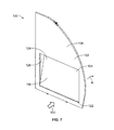
図1は、本開示の一実施形態による、航空機10(または航空機組立体)などのビークルの上部斜視図である。航空機10は、例えば2つのターボファンエンジン14を含むことができる推進システム12を含むことができる。随意に、推進システム12は、図示より多いまたは少ないエンジン14を含むことができる。エンジン14は、航空機10の翼16によって支持される。他の実施形態では、エンジン14は、胴体18および/または尾部20によって支持され得る。尾部20は、水平安定板22および垂直安定板24も支持することができる。
FIG. 1 is an upper perspective view of a vehicle such as an aircraft 10 (or aircraft assembly) according to an embodiment of the present disclosure.
航空機10の胴体18は内部客室を画定し、内部客室は、操縦室と、1つまたは複数の作業セクション(例えば、調理室、乗員の機内持ち込み手荷物領域、および類似の領域)と、1つまたは複数の乗客セクション(例えば、ファーストクラスセクション、ビジネスクラスセクション、およびエコノミークラスセクション)と、後方休息領域が配置され得る後方セクションと、を含むことができる。セクションはそれぞれ、客室移行領域によって隔てられてもよく、客室移行領域は、1つまたは複数のモニュメント、例えば、調理室、洗面所、クロゼット、仕切り、クラス仕切り組立体、および/または類似のものを含むことができる。
以下で説明するように、航空機10は、固定部分(固定壁など)を含むことができる乗客座席に近接する1つまたは複数のモニュメントと、航空機内に作用する終極荷重、航空機の例えば16G以上の顕著な減速が起きた場合に前方に展開するように構成された可動部分(展開可能な隙間パネルなど)と、を含むことができる。あるいは、終極荷重は16Gより大きくても小さくてもよい。
As described below, the
あるいは、航空機の代わりに、本開示の諸実施形態は、自動車、バス、機関車および列車、ウォータクラフト、スペースクラフトなどの他の様々なビークルに使用されてもよい。 Alternatively, instead of an aircraft, the embodiments of the present disclosure may be used in various other vehicles such as automobiles, buses, locomotives and trains, watercraft, spacecraft and the like.
図2Aは、本開示の一実施形態による航空機の内部客室30の上平面図である。内部客室30は航空機の胴体32内にあり得る。例えば、1つまたは複数の胴体壁が内部客室30を画定することができる。内部客室30は、前方セクション33、ファーストクラスセクション34(または、例えばファーストクラススイート、客室)、ビジネスクラスセクション36、調理室などのモニュメントを含む前方調理室ステーション38、拡張エコノミーもしくはコーチセクション40、および標準エコノミーもしくはコーチセクション42、および後方セクション44を含む多数のセクションを含み、後方セクション44は洗面所や調理室などのモニュメントを含むことができる。内部客室30は、図示より多いまたは少ないセクションを含み得ることを理解すべきである。例えば、内部客室30は、ファーストクラスセクションを含んでいなくてもよく、図示よりも多いまたは少ない調理室ステーションを含んでいてもよい。セクションはそれぞれ、客室移行領域46によって隔てられてもよく、客室移行領域46は、通路48相互間にクラス仕切り組立体などのモニュメントを含むことができる。
FIG. 2A is an upper plan view of the
図2Aに示されているように、内部客室30は、後方セクション44につながる2本の通路50および52を含む。随意に、内部客室30は、図示より多いまたは少ない通路を有することができる。例えば、内部客室30は、後方セクション44につながる、内部客室30の中心を貫通して延伸する単通路を含むことができる。
As shown in FIG. 2A, the
内部客室30は多数のモニュメントを含む。例えば、内部客室30は、洗面所60、調理室62、クロゼットまたは仕切り64、などを含む。
図2Bは、本開示の一実施形態による航空機の内部客室80の上平面図である。内部客室80は航空機の胴体81内にあり得る。例えば、1つまたは複数の胴体壁が内部客室80を画定することができる。内部客室80は、操縦室89、乗客座席83を有する主客室82、および主客室82の後ろの後方セクション85を含む多数のセクションを含む。内部客室80は、図示より多いまたは少ないセクションを含み得ることを理解すべきである。
FIG. 2B is a top plan view of the aircraft
内部客室80は、後方セクション85につながる単通路84を含むことができる。単通路84は、後方セクション85につながる内部客室80の中心を貫通して延伸することができる。例えば、単通路84は、内部客室80の中心縦断面と同軸上に整列され得る。
The
図3は、本開示の一実施形態によるモニュメント壁組立体100の後部斜視図である。モニュメント壁組立体100は、固定壁102などの固定部分と固定壁102に連結された展開可能な隙間パネル104などの可動部分とを含むことができる。
FIG. 3 is a rear perspective view of the
固定壁102は、アウトボード縁部110、ベース縁部112、およびインボード縁部114を介して反対側後面108に接続された前面106を含む。アウトボード縁部110は、1つまたは複数の固定部材116(例えば、ブラケット、締め具、取付具、および/または類似のもの)などによって、例えば、航空機の胴体の内部部分にしっかりと取り付けられるように構成される。ベース縁部112は、1つまたは複数の固定部材117(例えば、シートトラック、ハードポイント、ブラケット、締め具、および/または類似のものにしっかりと連結されるように構成された取付具)などによって、航空機の内部客室内の床にしっかりと連結されるように構成される。インボード縁部114は、航空機の内部客室の通路に近接する露出した縁部面とすることができる。
The fixed
隙間パネル104は、内部客室内の1つまたは複数の座席に面するように構成された後面118を含む。隙間パネル104にほぼ前進方向の終極荷重(例えば、航空機の顕著な減速によって引き起こされる)が作用すると、隙間パネル104の重量もしくは質量および慣性は、隙間パネル104を内部客室内の座席から離れる向きに前方に展開させ、それによって、FAAによって規定されている十分な頭部傷害基準(HIC)の隙間が提供される。
The
隙間パネル104と固定壁102との間の移行領域に覆い120が配置され得る。覆い120は、その隙間パネル104を静的非展開状態にある間に隠す積層板、壁紙、塗装、および/または類似のものとすることができる。
A
隙間パネル104は、下端部122で固定壁102に枢動可能に固定され得る。例えば、ヒンジ、シャフト、回転ピンなど(図3の見えないところに隠れている)が、隙間パネル104を下端部122で固定壁102に枢動可能に連結することができる。
The
シャーピン(図3の見えないところに隠れている)などの1つまたは複数の解放装置が、隙間パネル104を上端部124で固定壁に連結することができる。解放装置は、例えば、力または加速の所定の閾値で作動するように構成された任意の構造的取付分離機構とすることができる。少なくとも1つの実施形態では、加速度計が、アクチュエータ機構に信号を送るためにセンサとして使用されてもよい。少なくとも1つの実施形態において、解放装置は、終極前方運動力などの所定の力が作用すると解放する(例えば、せん断し破断する)ように構成されたシャーピンとすることができる。終極力は、隙間パネル104の重量もしくは質量および慣性によりシャーピンを破断させる。
One or more release devices, such as a shear pin (hidden invisible in FIG. 3), can connect the
少なくとも1つの実施形態において、隙間パネル104は、固定壁102を貫通して形成された開口部内に固定され、例えば、1つまたは複数のヒンジ、シャーピン、筋かい支持体、および/または類似のものによって固定壁102に直接連結することができる。少なくとも1つの実施形態において、隙間パネル104は、隙間パネル104の本体を取り囲むフレームを含むことができる。本体は、1つまたは複数のヒンジ、シャーピン、筋かい支持体、および/または類似のものによってフレームに連結することができる。フレームは、固定壁102の開口部内に取り付けることができる。
In at least one embodiment, the
図3に示されているように、隙間パネル104は非展開状態である。非展開状態では、隙間パネル104の後面118は一般に、固定壁102の後面108と同一平面であり得る。このようにして、モニュメント壁組立体100の後面(後面108および118を含む)は、隙間パネル104が非展開状態であるときに単一共通平面に存在することができる。
As shown in FIG. 3, the
図4は、モニュメント壁組立体100の後部分解図である。固定壁102は内側開口部126を画定することができ、内側開口部126の中に隙間パネル104が配置される。ブラケット128が、隙間パネル104の上端部124から上方に延伸する。各ブラケット128は、シャーピン134の外端部132を保持するように構成された外側保持部130を含むことができる。ブラケット128は、内側開口部126の上部を画定する、固定壁102の上方内側縁部138内に形成された相互ブラケット136と対合するように構成される。各ブラケット136は、両側の溝142の間に延伸する中心保持部140を含むことができる。両側の溝142は、ブラケット128の外側保持部130を受容するように構成される、中心保持部140は、外端部132を互いに連結するシャーピン134の中心本体144を保持するように構成される。随意に、ブラケット128は中心保持部を含むことができ、ブラケット136は外側保持部130を含む。他の実施形態では、シャーピンは、閾値力または閾値荷重が隙間パネル上に与えられたときに単一箇所がせん断または破断することができる。他の実施形態では、シャーピンは、隙間パネルから固定壁の中にまで突出することができ、またはその逆も同様であり、例えば、ばね荷重ピンなどが突出することができる。
FIG. 4 is a rear exploded view of the
図5は、シャーピン134によって固定壁102に連結された隙間パネル104の後部図である。非展開状態では、隙間パネル104の上端部124は連続したシャーピン134によって固定壁102に連結され、シャーピン134は壊れていない。シャーピン134は、例えば、側面アクセス穴から隙間パネル104の中に取り付けることができる。
FIG. 5 is a rear view of the
図6は、隙間パネル104と固定壁102との間で破断したシャーピン134の後部図である。モニュメント壁組立体100が所定の閾値を満たすまたは超える力(終極荷重の力など)を受けると、隙間パネル104の重量および慣性は、中心本体144から外端部132を小直径ネック部146で破断させるのに十分な力をシャーピン134の中に及ぼす。
FIG. 6 is a rear view of the
図4〜図6を参照すると、各シャーピン134は、破断する前に所定の荷重に耐えるように構成される。例えば、各シャーピン134は、閾値荷重300ポンド(136kg)の力に耐えるように構成することができる。シャーピン134にかかる作用荷重が300ポンドの力を超えると、シャーピン134は図6に示されているように破断する。随意に、閾値荷重は300ポンドの力より大きくても小さくてもよい。例えば、閾値荷重は400ポンド(181kg)の力とすることができる。このようにして、シャーピン134は、乗客が隙間パネル104に寄りかかるだけであれば、無傷で破断しないままである。
With reference to FIGS. 4-6, each
モニュメント壁組立体100が終極荷重(航空機の突然の減速中に作用されるような荷重)を受けると、隙間パネル104の重量および慣性はシャーピン134を破断させ、隙間パネル104を固定壁102に対して前方に枢動させる。たった1つの非限定的な例として、終極荷重は16Gに予め決定されてもよく、隙間パネルの重量は25ポンドとすることができる。この例では、シャーピン134の中に作用する力は400ポンドの力(16G×25ポンド=400ボンド)であり、この力は、図6に示されているようにシャーピン134を破断させる閾値力とすることができる。
When the
シャーピン134は、機械的過負荷の場合に(例えば、モニュメント壁組立体100が終極荷重を受けたときに)せん断する、またはその他の方法で破断するように設計される。シャーピン134は犠牲的であり、機械的ヒューズと見なすことができる。各シャーピン134は、金属、プラスチック、および/または類似の材料で形成することができる。
The
図4に示されているように、隙間パネル104は、非展開状態で2つのシャーピン134によって固定壁102に連結することができる。あるいは、2つより多いまたは少ないシャーピン134が使用されてもよい。例えば、非展開状態では、隙間パネル104は、単一のシャーピン134によって固定壁102に連結することができる。少なくとも1つの実施形態において、非展開状態では、隙間パネル104は、3つ以上のシャーピン134によって固定壁102に連結することができる。他の実施形態では、シャーピンは、閾値力または閾値荷重が隙間パネル上に与えられたときに単一箇所がせん断または破断することができる。他の実施形態では、シャーピンは、隙間パネルから固定壁の中へ突出することができ、またはその逆も同様であり、例えば、ばね荷重ピンなどが隙間パネルの縁部面に対してほぼ垂直の方向に突出することができる。
As shown in FIG. 4, the
図7は、展開状態の隙間パネル104を有するモニュメント壁組立体100の後部斜視図である。図8は、展開状態の隙間パネル104を有するモニュメント壁組立体100の側面図である。図7および図8を参照すると、モニュメント壁組立体100が、隙間パネル104の後面118の方へかつその中に向けられた終極荷重150を前面152に向かって受けると、隙間パネル104の重量および慣性はシャーピン134(図4〜図6に示されている)を破断させ、それによって、隙間パネル104を、隙間パネル104を固定壁102に枢動可能に連結する軸線154(1つまたは複数のヒンジ、心棒、および/または類似のものによって画定される軸線など)を中心に円弧Aの方向に前方へ枢動させる。したがって、上端部124は前方へ揺動し、それによって、隙間パネル104の後面118と向かい合う座席162内に座っている乗客160のための追加のヘッドクリアランス領域を提供する。展開中、覆い(図3に示されている覆い120など)があれば、隙間パネル104と固定壁102との間の界面付近で引き裂かれる。したがって、隙間パネル104が固定壁102に対して前方に展開すると十分なHICクリアランス領域が存在するので、座席162はモニュメント壁組立体100に近づけて配置することができる。
FIG. 7 is a rear perspective view of the
図示のように、終極荷重150を受けると、乗客160の頭部170は前方に揺動し得る。同時に隙間パネル104が前方に展開するので、乗客160は、乗客160の頭部をモニュメント壁組立体100のどの部分にもぶつける危険性はない。
As shown, under the
固定物180が、隙間パネル104の後面118および/または外側面に固定されかつ/またはその後面118および/または外側面から外方に延伸することができる。固定物180は、マガジンポケット、収納箱、モニタ、および/または類似のものとすることができる。随意に、隙間パネル104は固定物180を含んでいなくてもよい。固定物180は隙間パネル104に重みを加える。したがって、固定物180の重量は、終極荷重150が作用すると隙間パネル104のより容易で円滑な展開を促進することができる。
The
さらに、筋かい部材190が、隙間パネル104の上端部124を固定壁102に枢動可能にかつ/または摺動可能に連結することができる。隙間パネル104が展開するにつれて、筋かい部材190は、隙間パネル104が軸線154を中心に円弧Aの逆方向に枢動して戻るのを妨げる外方展開位置にまで枢動しかつ/または摺動する。筋かい部材190は、ストラット、ケーブル、伸縮部材、エネルギー吸収装置、および/または類似のものとすることができる。筋かい部材190は、隙間パネル104の外側縁部に固定することができる。1つまたは複数の筋かい部材190が使用されてもよい。
Further, the
モニュメント壁組立体100は、隙間パネル104を展開させるために終極荷重エネルギーを取り入れるように構成される。例えば、モニュメント壁組立体100は、モニュメント壁組立体100を含むビークル内に終極荷重エネルギーが作用すると展開する。モニュメント壁組立体100は、様々なモニュメントの一部、例えば、洗面所、カートを格納する調理室、仕切り壁、クラス移行壁、クロゼット、および/または類似のものの後方部分とすることができる。
The
図9は、本開示の一実施形態による、展開状態の隙間パネル202を有するモニュメント壁組立体200の後部斜視図である。図10は、展開状態の隙間パネル202を有するモニュメント壁組立体200の側面図である。図9および図10を参照すると、モニュメント壁組立体200は、隙間パネル202が、下端部210の代わりに上端部208で軸線206を中心に固定壁204に対して枢動して展開状態にまで開くことを除けば、モニュメント壁組立体100と類似している。終極荷重212がモニュメント壁組立体200内に作用するとき、下端部210は、隙間パネル202が軸線206を中心に枢動して開くにつれて円弧Bの方向に揺動して開く。
FIG. 9 is a rear perspective view of the
図11は、本開示の一実施形態による、展開状態の隙間パネル302を有するモニュメント壁組立体300の後部斜視図である。図12は、展開状態の隙間パネル302を有するモニュメント壁組立体300の側面図である。図11および図12を参照すると、モニュメント壁組立体300は、隙間パネル302が、当該の近位端部308および310で下方セグメント306に枢動可能に連結された上方セグメント304を含むことを除けば、モニュメント壁組立体100と類似している。隙間パネル302は、互いに枢動可能に連結された、セグメント304および306などの2つのパネルを含むことができる。下方セグメント306の下端部312は、軸線314によって固定壁316に枢動可能に固定される。上端部318は、固定壁316を貫通する開口部324を画定する内側縁部322を通って形成されたトラック320内に軸受などによって摺動可能に保持される。終極荷重330がモニュメント壁組立体300内に作用するとき、上方セグメント304および下方セグメント306は、下方セグメント306が軸線314を中心に前方へ枢動し、上方セグメント304の上端部318が矢印Cの方向に下方へ摺動し、上方セグメント304も上端部318を中心に枢動するので、両セグメント間の枢動界面を中心に前方へ枢動する。
FIG. 11 is a rear perspective view of the
図13は、本開示の一実施形態による、展開状態の隙間パネル402を有するモニュメント壁組立体400の後部斜視図である。図14は、展開状態の隙間パネル402を有するモニュメント壁組立体400の側面図である。図13および図14を参照すると、モニュメント壁組立体400は、パンタグラフ式隙間パネル402を含むことを除けば、モニュメント壁組立体100と類似しており、パンタグラフ式隙間パネル402は、モニュメント壁組立体400内に終極荷重420が作用すると、モニュメント壁組立体400が上部筋かい部材406および下部筋かい部材408を中心にパンタグラフ運動によって円弧Dの方向に展開状態にまで前下方に揺動する。筋かい部材406および408は、長さが同じでも異なっていてもよい。パンタグラフ構成という用語は、長さが同じまたは同等の上部リンク機構および下部リンク機構を含むことができる。少なくとも1つの実施形態において、パンタグラフ構成は、長さの異なるリンク機構を含むことができる。
FIG. 13 is a rear perspective view of the
図15は、本開示の一実施形態による、展開状態の隙間パネル502を有するモニュメント壁組立体500の後部斜視図である。図16は、展開状態の隙間パネル502を有するモニュメント壁組立体500の側面図である。図15および図16を参照すると、モニュメント壁組立体500は、隙間パネル502がモニュメント壁組立体500をシートトラックなどによって内部客室内の床に固定する取付具506に枢動可能に固定されることを除けば、モニュメント壁組立体100と類似している。取付具506は、終極荷重508がモニュメント壁組立体500内に作用するときに隙間パネル502が前方に枢動可能にそれることを可能にする。隙間パネル502の上端部510は、上述したように、非展開状態で1つまたは複数のシャーピンによって固定壁512に連結する。固定壁512は、1つまたは複数の固定部材520によって内部客室内の天井にしっかりと連結された固定ヘッダとすることができる。図15および図16に示されているように、隙間パネル502は、モニュメント壁組立体500の高さの半分より実質的に大きい部分を占めることができる。随意に、隙間パネル502は、図15および図16に示されているより短くても長くてもよい。例えば、少なくとも1つの実施形態において、隙間パネル502は、モニュメント壁組立体500の全高さであり、1つまたは複数のシャーピンによって内部客室内の天井に取外し可能に連結することができる(別個の異なる固定壁部分に連結するのではない)。
FIG. 15 is a rear perspective view of the
隙間パネル502は、取付具506などによって内部客室542の床540に枢動可能に固定される。隙間パネル502は、上述したように、少なくとも1つのシャーピンで内部客室542の固定壁512または天井544にも連結される。シャーピンは、所定の閾値を満たすまたは超える力、例えばモニュメント壁組立体500内に作用する終極荷重が作用すると破断するように構成される。
The
図17Aは、本開示の一実施形態による、航空機の内部客室600の一部の上平面図である。内部客室600は、モニュメント604の後ろの座席列602を含む。モニュメント604はそれぞれ、トイレ606および流し608を含む洗面所とすることができる。モニュメント604は、座席列602からモニュメント壁組立体610によって隔てられる。モニュメント壁組立体610は、図3〜図16に関して上述したモニュメント壁組立体のいずれでもよい。
FIG. 17A is an upper plan view of a part of the
図17Bは、本開示の一実施形態による、安全な非展開状態の隙間パネル605を有する洗面所604の内部斜視図である。図17Cは、本開示の一実施形態による、展開状態の隙間パネル605を有する洗面所の内部斜視図である。図17Bおよび図17Cを参照すると、後方セクションから前方セクションの方へ向けられた終極荷重607が作用すると、隙間パネル605は洗面所604の内部空間609の中に展開する。図示のように、トイレ606は、モニュメント壁組立体610に隣接する、またはそうでなければ近接することができる。しかし、トイレ606および流し608は、内部空間609の他の様々な部分に配置することができる。
FIG. 17B is an internal perspective view of a
図17Bおよび図17Cに示されているように、隙間パネル605は非占有の洗面所604の中に展開され得る。洗面所604は、航空機の地上走行、離陸、および着陸中、終極荷重が航空機内に作用することがないときに非占有である。
As shown in FIGS. 17B and 17C, the
図18は、本開示の一実施形態による、航空機の内部客室700の一部の上平面図である。内部客室700は、モニュメント704の後ろの座席列702を含む。モニュメント704は、食品飲料カートを受容するように構成されたベイ706を含む調理室とすることができる。モニュメント704は、座席列702からモニュメント壁組立体710によって隔てられる。モニュメント壁組立体710は、図3〜図16に関して上述したモニュメント壁組立体のいずれでもよい。モニュメント壁組立体710の隙間パネルは、調理室内の未使用の空所内に展開することができる。
FIG. 18 is an upper plan view of a part of the
図19は、本開示の一実施形態による、座席列がモニュメント壁組立体に近づけて配置されるのを可能にするようにモニュメント壁組立体を操作する方法の流れ図である。方法は800で始まり、隙間パネルが、1つまたは複数の枢動界面などによって内部客室の固定壁または固定部分に可動に固定される。802で、隙間パネルは、1つまたは複数のシャーピンによって内部客室の固定壁または固定部分に連結される。 FIG. 19 is a flow chart of a method of manipulating the monument wall assembly to allow the seat rows to be placed closer to the monument wall assembly according to an embodiment of the present disclosure. The method begins at 800, where the crevice panel is movably secured to a fixed wall or portion of the interior cabin, such as by one or more pivotal interfaces. In 802, the crevice panel is connected to a fixed wall or portion of the interior cabin by one or more shear pins.
804で、力がモニュメント壁組立体内に作用し、その力はシャーピンが破断する所定の展開閾値を超えるかどうかが判定される。所定の展開閾値を満たしていないまたは超えていない場合、方法は806に進み、806で、シャーピンは、シャーピンの構造を維持するとともに隙間パネルを非展開状態に保つ。次いで、方法は804に戻る。しかし、作用力が所定の展開閾値を超えた場合、方法は804から808へ進み、シャーピンは破断し、隙間パネルは展開状態にまで移動する。 At 804, a force acts on the monument wall assembly to determine if the force exceeds a predetermined deployment threshold at which the shear pin breaks. If the predetermined deployment threshold is not met or exceeded, the method proceeds to 806, at 806, where the shear pin maintains the structure of the shear pin and keeps the crevice panel unexpanded. The method then returns to 804. However, if the acting force exceeds a predetermined deployment threshold, the method proceeds from 804 to 808, the shear pin breaks, and the gap panel moves to the deployed state.
図20は、本開示の一実施形態による、ビークル902の内部客室900の簡略内部図である。内部客室900は、座席906および1つまたは複数のモニュメント908を支持する床904を含む。座席906は、複数の取付具912によってシートトラック910に固定することができる。同様に、モニュメント908は、1つまたは複数の取付具914によって床904に固定することができる。
FIG. 20 is a simplified internal view of the
各取付具914は係止部分916を含むことができる。1つまたは複数の壊れやすい要素918(1つまたは複数のシャーピンなど)が後方取付具914をモニュメント908の本体920に連結する。前方取付具914はピボットヒンジ922を含むことができる。モニュメント908は、上述した任意のタイプのものとすることができる。随意に、モニュメント908は、1つまたは複数の取付具、取付台、締め具、および/または類似のもの(これらのうちの少なくともいくつかはシャーピンなどの壊れやすい要素を含むことができる)によって内部客室900内の他の様々な部分、例えば、天井930、アウトボード壁932、床904、および/または類似のものに固定することができる。
Each
終極荷重が後方から前方へ矢印950の方向に作用するとき、壊れやすい要素918は破断する、またはその他の方法で解放し、終極荷重は、破線908’で示されているように、ピボットヒンジ922を中心にモニュメント908の本体920を前方に枢動させる。このようにして、終極荷重が内部客室900内に作用するときに追加のヘッドクリアランス空間が提供される。
When the ultimate load acts from rear to front in the direction of
図21は、本開示の一実施形態による、ビークル902の内部客室900の簡略内部図である。固定物960がモニュメント908に固定され得る。固定物960は、機内の娯楽システム、マガジンラック、収納キャビネット、乳児用おむつ交換台、および/または類似のものとすることができる。固定物960は、終極荷重がモニュメント908内に矢印950の方向に作用しかつ通常運転荷重下にないときに壊れやすい要素918が解放するようにする有用な質量体となる。さらに、メカニカルアドバンテージ装置970(レバーなど)がピボット点またはピボット軸線980を画定するように使用されてもよく、本体920は、終極荷重が矢印950の方向に作用するときにピボット点またはピボット軸線980を中心に枢動する。
FIG. 21 is a simplified internal view of the
図20および図21を参照すると、モニュメント908自体は、終極荷重がモニュメント908内に矢印950の方向に作用するときに非展開状態から展開状態にまで移動するように構成される。壊れやすい要素918(シャーピンなど)はモニュメント908の先端に、例えば床取付具または天井取付具にまたはそれに近接して配置することができる。
With reference to FIGS. 20 and 21, the
モニュメント908は、本体920などの展開可能な部分を含む。展開可能な部分は、所定の閾値(終極荷重など)を満たすまたは超える力がモニュメント908内に作用するときに非展開状態から展開状態(図20に908’として示されている)にまで移動するように構成される。
図1〜図21を参照すると、本開示の諸実施形態では、航空機内の座席数を増大させるために、航空機の客室内の1つまたは複数の座席をモニュメントに近づけて安全に配置するシステムおよび方法が提供される。本開示の諸実施形態では、すべての関連FAA安全要件に適合しながらも、航空機の客室内の1つまたは複数の座席をモニュメントに近づけて安全に配置するシステムおよび方法が提供される。 With reference to FIGS. 1-21, in embodiments of the present disclosure, a system and a system in which one or more seats in an aircraft cabin are safely placed close to the monument in order to increase the number of seats in the aircraft. The method is provided. The embodiments of the present disclosure provide a system and method for safely arranging one or more seats in the cabin of an aircraft close to the monument while meeting all relevant FAA safety requirements.
本開示の諸実施形態では、ビークルに搭乗する安全性の向上、ビークルの内部客室内の空間利用の改善、ならびに軽量かつ単純で費用効率の高い審美的に控えめな保守不要のシステムおよび組立体が提供される。 The embodiments of the present disclosure include improved vehicle boarding safety, improved space utilization in the vehicle's interior cabin, and lightweight, simple, cost-effective, aesthetically discreet, maintenance-free systems and assemblies. Provided.
上の(top)、底の(bottom)、下の(lower)、中央の(mid)、横の(lateral)、水平の(horizontal)、垂直の(vertical)、前の(front)などの様々な空間および方向を示す用語は、本開示の諸実施形態を説明するために用いられることがあるが、このような用語は、図面に示されている向きに関して用いられているにすぎない。向きは、上部が下部であり、逆も同様であり、水平が垂直になる、などとなるように、反転、回転、またはその他の方法で変更され得る。 Top, bottom, bottom, center (mid), horizontal (lateral), horizontal (horizontal), vertical (vertical), front (front), etc. Space and orientation terms may be used to describe embodiments of the present disclosure, but such terms are only used with respect to the orientations shown in the drawings. The orientation can be flipped, rotated, or otherwise changed so that the top is the bottom, vice versa, the horizontal is vertical, and so on.
本明細書では、タスクまたはオペレーションを実行する「ように構成される(configured to)」構造、制限、または要素は、そのタスクまたはオペレーションに対応する態様で、特に構造的に形成、構築、または適合される。明瞭にするとともに、疑念を避けるために、タスクまたはオペレーションを実行するために修正することができるにすぎない対象物は、本明細書ではタスクまたはオペレーションを実行する「ように構成される」ものではない。 As used herein, a structure, restriction, or element "configured to" performing a task or operation is specifically structurally formed, constructed, or adapted in a manner that corresponds to that task or operation. Will be done. Objects that can only be modified to perform a task or operation, for clarity and to avoid doubt, are not herein "configured to" perform the task or operation. No.
上記の説明は例示するためのものであり、限定するものではないことを理解すべきである。例えば、上述した諸実施形態(および/またはそれら実施形態の態様)は互いに組み合わせて使用することができる。加えて、特定の状況または材料を本開示の様々な実施形態の教示に、それらの実施形態の範囲から逸脱することなく適合させるために多くの修正がなされ得る。本明細書に記述されている材料の寸法およびタイプは、本開示の様々な実施形態のパラメータを定義するためのものであり、それらの実施形態は決して限定するものではなく、例示的な実施形態である。他の多くの実施形態が、当業者には上記の説明を再検討したときに明らかになるであろう。したがって、本開示の様々な実施形態の範囲は、添付の特許請求の範囲を、かかる特許請求の範囲に属する同等物の全範囲とともに参照して決定されるべきである。添付の特許請求の範囲において、「含む(including)」および「in which」という用語は、それぞれ「備える(comprising)」および「wherein」という用語に相当する平易な英語として用いられる。さらに、「第1の(first)」、「第2の(second)」、および「第3の(third)」などの用語は単にラベルとして用いられ、それらの用語の対象物に数値的要件を課すためのものではない。さらに、下記の特許請求の範囲の制限は、ミーンズプラスファンクション形式(means-plus-function format)で記載されず、このような特許請求の範囲の制限が、「〜ための手段(means for)」という言い回しに続いてさらなる構造のない機能の表明を明確に用いていない限り、米国特許法第112条(f)に基づいて解釈されるものではない。 It should be understood that the above description is for illustration purposes only and is not limiting. For example, the embodiments described above (and / or aspects of those embodiments) can be used in combination with each other. In addition, many modifications may be made to adapt a particular situation or material to the teachings of the various embodiments of the present disclosure without departing from the scope of those embodiments. The dimensions and types of materials described herein are for defining parameters of various embodiments of the present disclosure, the embodiments of which are by no means limiting, and exemplary embodiments. Is. Many other embodiments will become apparent to those skilled in the art upon review of the above description. Therefore, the scope of the various embodiments of the present disclosure should be determined with reference to the appended claims, along with the full range of equivalents belonging to such claims. In the appended claims, the terms "including" and "in which" are used as plain English equivalents to the terms "comprising" and "where in," respectively. In addition, terms such as "first," "second," and "third" are simply used as labels to provide numerical requirements for the objects of those terms. Not for imposing. Furthermore, the following claims limitation is not described in the means-plus-function format, and such claims limitation is "means for". It is not construed under Section 112 (f) of the US Patent Act unless it is explicitly used to follow the phrase, a statement of function without further structure.
本明細書は、最良の形態を含む本開示の様々な実施形態を開示するために、そしてまた、任意の装置もしくはシステムを製作し使用すること、および任意の組み入れられた方法を実行することを含む本開示の様々な実施形態を当業者が実施できるようにするためにも、複数の例を使用している。本開示の様々な実施形態の特許可能な範囲は、特許請求の範囲によって定義され、当業者が想起する他の例を含むことができる。このような他の例は、それらの例が特許請求の範囲の文言と異ならない構造要素を有する場合、またはそれらの例が特許請求の範囲との非実質的差異を有する同等の構造要素を含む場合、特許請求の範囲内にあることを意図している。 The present specification is intended to disclose various embodiments of the present disclosure, including the best embodiments, and also to make and use any device or system, and to carry out any incorporated method. A plurality of examples are also used to enable those skilled in the art to implement the various embodiments of the present disclosure, including. The patentable scope of the various embodiments of the present disclosure is defined by the claims and may include other examples recalled by those skilled in the art. Such other examples include cases where those examples have structural elements that do not differ from the wording of the claims, or equivalent structural elements where those examples have a non-substantial difference from the claims. If so, it is intended to be within the scope of the claims.
さらに、本開示は下記条項による諸実施形態を含む。 In addition, the disclosure includes embodiments under the following provisions.
条項1.ビークルの内部客室内に配置されるように構成されたモニュメントであって、
所定の閾値を満たすまたは超える力がモニュメント内に作用するときに非展開状態から展開状態にまで移動するように構成された展開可能な部分
を備える、モニュメント。
Clause 1. A monument designed to be placed in the vehicle's interior cabin
A monument with a deployable part that is configured to move from an undeployed state to a deployed state when a force that meets or exceeds a predetermined threshold acts within the monument.
条項2.展開可能な部分が、モニュメント壁組立体内に展開可能な隙間パネルを備え、隙間パネルが、所定の閾値を満たすまたは超える力がモニュメント壁組立体内に作用するときに非展開状態から展開状態にまで移動するように構成される、条項1に記載のモニュメント。 Clause 2. The deployable part comprises a deployable gap panel within the monument wall assembly, which moves from the undeployed state to the deployed state when a force that meets or exceeds a predetermined threshold acts on the monument wall assembly. The monument described in Clause 1, which is configured to be.
条項3.固定壁をさらに備え、隙間パネルが、固定壁に枢動可能に固定される第1の部分と固定壁に少なくとも1つの解放装置によって連結される第2の部分とを備え、少なくとも1つの解放装置が、所定の閾値を満たすまたは超える力が作用すると解放するように構成される、条項2に記載のモニュメント。 Clause 3. It further comprises a fixed wall, the crevice panel comprising a first portion pivotally fixed to the fixed wall and a second portion connected to the fixed wall by at least one release device, at least one release device. However, the monument described in Clause 2 is configured to be released when a force that meets or exceeds a predetermined threshold is applied.
条項4.第1の部分が下端部を備え、第2の部分が上端部を備える、条項3に記載のモニュメント。 Clause 4. The monument described in Clause 3, where the first part has the lower end and the second part has the upper end.
条項5.第1の部分が上端部を備え、第2の部分が下端部を備える、条項3に記載のモニュメント。 Clause 5. The monument described in Clause 3, where the first part has the upper end and the second part has the lower end.
条項6.隙間パネルが、下方セグメントに枢動可能に連結された上方セグメントを備える、条項2に記載のモニュメント。 Clause 6. The monument described in Clause 2, wherein the crevice panel comprises an upper segment that is pivotally connected to a lower segment.
条項7.隙間パネルが、非展開状態から展開状態にまでパンタグラフ運動によって移動するように構成されたパンタグラフ式隙間パネルである、条項2に記載のモニュメント。 Clause 7. The monument described in Clause 2, which is a pantograph-type crevice panel configured to move the crevice panel from the undeployed state to the unfolded state by a pantograph motion.
条項8.隙間パネルが、内部客室の床に枢動可能に固定されるように構成された第1の部分および内部客室の固定壁もしくは天井の一方に少なくとも1つのシャーピンで連結されるように構成された第2の部分を備え、少なくとも1つのシャーピンが、所定の閾値を満たすまたは超える力が作用すると破断するように構成される、条項2に記載のモニュメント。 Clause 8. The crevice panel is configured to be connected by at least one shear pin to either the first part configured to be pivotally secured to the floor of the interior cabin and the fixed wall or ceiling of the interior cabin. The monument according to Clause 2, which comprises two parts and is configured so that at least one shear pin breaks when a force that meets or exceeds a predetermined threshold is applied.
条項9.所定の閾値を満たすまたは超える力が、重力の少なくとも9倍の終極荷重である、条項2に記載のモニュメント。 Clause 9. The monument described in Clause 2, where the force that meets or exceeds a given threshold is a ultimate load that is at least nine times gravity.
条項10.隙間パネルは、隙間パネルが展開状態から移動して非展開状態に戻るのを妨げる1つまたは複数の筋かい部材を備える、条項2に記載のモニュメント。
条項11.隙間パネルの上に、非展開状態で隙間パネルの少なくとも一部分を隠す覆いをさらに備える、条項2に記載のモニュメント。 Clause 11. The monument described in Clause 2 with an additional cover over the crevice panel that hides at least part of the crevice panel in the undeployed state.
条項12.モニュメントに固定された固定物をさらに備え、固定物が、所定の閾値を満たすまたは超える力がモニュメント内に作用するときに展開状態にまでの移動を促進する有用な質量体となる、条項1に記載のモニュメント。
条項13.固定物が、隙間パネルの前面または後面に固定される、条項12に記載のモニュメント。
Clause 13. The monument described in
条項14.展開可能な部分がモニュメントの本体を備え、本体が、所定の閾値を満たすまたは超える力がモニュメント内に作用するときに非展開状態から展開状態にまで移動するように構成される、条項2に記載のモニュメント。
条項15.本体が、壊れやすい部分を介して本体に連結された係止部分を含む少なくとも1つの取付具によって内部客室の一部分に固定されるように構成される、条項14に記載のモニュメント。
Clause 15. The monument according to
条項16.本体が、1つまたは複数のピボットヒンジを含む少なくとも1つの取付具によって内部客室の一部分に固定されるように構成される、条項14に記載のモニュメント。
条項17.本体が、所定の閾値を満たすまたは超える力がモニュメント内に作用するときに前方に枢動するように構成される、条項14に記載のモニュメント。
Clause 17. The monument according to
条項18.床取付具または天井取付具の一方または両方に近接して配置される1つまたは複数の壊れやすい要素をさらに備える、条項14に記載のモニュメント。
条項19.
内部客室と、
内部客室内の複数の座席と、
複数の座席のうちの少なくとも1つに近接する、展開可能な部分を含むモニュメントであって、展開可能な部分が、所定の閾値を満たすまたは超える力がモニュメント内に作用するときに非展開状態から展開状態にまで移動するように構成される、モニュメントと、
を備えるビークル。
Clause 19.
Inside rooms and
With multiple seats in the internal cabin,
A monument that contains a deployable portion that is close to at least one of a plurality of seats, from the undeployed state when the deployable portion exerts a force in the monument that meets or exceeds a predetermined threshold. Monuments and monuments that are configured to move to the unfolded state,
Vehicle with.
条項20.展開可能な部分が、モニュメント壁組立体内に展開可能な隙間パネルを備え、隙間パネルが、所定の閾値を満たすまたは超える力がモニュメント壁組立体内に作用するときに非展開状態から展開状態にまで移動するように構成される、条項19に記載のビークル。
条項21.モニュメント壁組立体が固定壁をさらに備え、隙間パネルが、固定壁に枢動可能に固定される第1の部分と固定壁に少なくとも1つのシャーピンによって連結される第2の部分とを備え、少なくとも1つのシャーピンが、所定の閾値を満たすまたは超える力が作用すると破断するように構成される、条項20に記載のビークル。
Clause 21. The monument wall assembly further comprises a fixed wall, and the crevice panel comprises a first portion pivotally fixed to the fixed wall and a second portion connected to the fixed wall by at least one shear pin, at least. The vehicle according to
条項22.隙間パネルが、内部客室の床に枢動可能に固定されるように構成された第1の部分と内部客室の固定壁または天井の一方に少なくとも1つのシャーピンで連結されるように構成された第2の部分とを備え、少なくとも1つのシャーピンが、所定の閾値を満たすまたは超える力が作用すると破断するように構成される、条項20に記載のビークル。
条項23.隙間パネルは、隙間パネルが展開状態から移動して非展開状態に戻るのを妨げる1つまたは複数の筋かい部材を備える、条項20に記載のビークル。
Clause 23. The vehicle according to
条項24.モニュメント壁組立体が、隙間パネルの上に、非展開状態で隙間パネルを隠す覆いをさらに備える、条項20に記載のビークル。
条項25.モニュメントに固定された固定物をさらに備え、固定物が、所定の閾値を満たすまたは超える力がモニュメント内に作用するときに展開状態にまでの移動を促進する有用な質量体となる、条項20に記載のビークル。
Clause 25.
条項26.展開可能な部分がモニュメントの本体を備え、本体が、所定の閾値を満たすまたは超える力がモニュメント内に作用するときに非展開状態から展開状態にまで移動するように構成される、条項19に記載のビークル。 Clause 26. As described in Clause 19, the deployable part comprises the body of the monument, which is configured to move from the undeployed state to the deployed state when a force that meets or exceeds a predetermined threshold acts within the monument. Vehicle.
条項27.本体が、壊れやすい部分を介して本体に連結される係止部分を含む少なくとも1つの取付具によって内部客室の一部分に固定される、条項26に記載のビークル。 Clause 27. The vehicle according to Clause 26, wherein the body is secured to a portion of the interior cabin by at least one fixture, including a locking portion that is connected to the body via a fragile portion.
条項28.本体が、1つまたは複数のピボットヒンジを含む少なくとも1つの取付具によって内部客室の一部分に固定される、条項26に記載のビークル。 Clause 28. The vehicle according to Clause 26, wherein the body is secured to a portion of the interior cabin by at least one fixture, including one or more pivot hinges.
条項29.本体が、所定の閾値を満たすまたは超える力がモニュメント内に作用するときに前方に枢動するように構成される、条項26に記載のビークル。 Clause 29. The vehicle according to Clause 26, wherein the body is configured to pivot forward when a force that meets or exceeds a predetermined threshold acts within the monument.
条項30.床取付具または天井取付具の一方または両方に近接して配置される1つまたは複数の壊れやすい要素をさらに備える、条項26に記載のビークル。
条項31.ビークルの内部客室内のモニュメントとの頭部の衝突を防止する方法であって、
モニュメントの展開可能な部分を内部客室の固定壁または固定部分に可動に固定するステップと、
展開可能な部分を非展開状態で1つまたは複数のシャーピンによって内部客室の固定壁または固定部分に連結するステップと、
所定の閾値を満たすまたは超える力がモニュメント内に作用するときに1つまたは複数のシャーピンを破断させるステップであって、破断させる動作が終極荷重を取り入れることによって起こるように構成される、ステップと、
展開可能な部分を破断動作によって乗客座席から離れる向きに展開状態にまで移動させるステップと、
を含む、方法。
Clause 31. A way to prevent head collisions with monuments in the vehicle's interior cabin,
Steps to movably fix the deployable part of the monument to the fixed wall or fixed part of the interior cabin,
With the step of connecting the deployable part to the fixed wall or fixed part of the interior cabin with one or more shear pins in the undeployed state,
A step that breaks one or more shear pins when a force that meets or exceeds a predetermined threshold acts in the monument, and the breaking action is configured to occur by incorporating an ultimate load.
A step to move the deployable part away from the passenger seat to the deployed state by breaking action,
Including methods.
条項32.展開可能な部分が隙間パネルを備える、条項31に記載の方法。
条項33.展開可能な部分がモニュメントの本体を備える、条項31に記載の方法。
条項34.移動させる動作が、展開可能な部分を洗面所または調理室の非占有部分または未使用部分の中へ前方展開状態にまで移動させることを含む、条項31に記載の方法。
10 航空機
12 推進システム
14 エンジン
18 翼
20 尾部
22 水平安定板
24 垂直安定板
30 内部客室
32 胴体
33 前方セクション
34 ファーストクラスセクション
36 ビジネスクラスセクション
38 前方調理室ステーション
40 拡張エコノミーもしくはコーチセクション
42 標準エコノミーもしくはコーチセクション
44 後方セクション
46 客室移行領域
48 通路
50 通路
52 通路
60 洗面所
62 調理室
64 クロゼットまたは仕切り
80 内部客室
81 胴体
82 主客室
83 乗客座席
84 単通路
85 後方セクション
89 操縦室
100 モニュメント壁組立体
102 固定壁
104 展開可能な隙間パネル
106 前面
108 後面
110 アウトボード縁部
112 ベース縁部
114 インボード縁部
116 固定部材
117 固定部材
118 後面
120 覆い
122 下端部
124 上端部
126 内側開口
128 ブラケット
130 外側保持部
132 外端部
134 シャーピン
136 相互プラケット
138 上方内側縁部
140 中心保持部
142 溝
144 中心本体
146 小直径ネック部
150 終極荷重
152 前面
154 後面
160 乗客
162 座席
170 頭部
180 固定物
190 筋かい部材
200 モニュメント壁組立体
202 隙間パネル
204 固定壁
206 軸線
208 上端部
210 下端部
212 終極荷重
300 モニュメント壁組立体
302 隙間パネル
304 上方セグメント
306 下方セグメント
308 近位端部
310 近位端部
312 下端部
314 軸線
316 固定壁
318 上端部
320 トラック
322 内側縁部
324 開口部
330 終極荷重
400 モニュメント壁組立体
402 隙間パネル
406 上部筋かい部材
408 下部筋かい部材
420 極限荷重
500 モニュメント壁組立体
502 隙間パネル
506 取付具
508 終極荷重
510 上端部
520 固定部材
540 床
542 内部客室
544 天井
600 内部客室
602 座席列
604 モニュメント
605 隙間パネル
606 トイレ
607 終極荷重
608 流し
609 内部空間
610 モニュメント壁組立体
700 内部客室
702 座席列
704 モニュメント
706 ベイ
710 モニュメント壁組立体
800 方法
900 内部客室
902 ビークル
904 床
906 座席
908 モニュメント
908’ 破線
910 シートトラック
912 取付具
914 取付具
916 係止部分
918 壊れやすい要素
920 本体
922 ピボットヒンジ
930 天井
932 アウトボード壁
950 矢印
960 固定物
970 メカニカルアドバンテージ装置
980 ピボット点またはピボット軸線
10 aircraft
12 Propulsion system
14 engine
18 wings
20 tail
22 Horizontal stabilizer
24 Vertical stabilizer
30 Interior rooms
32 torso
33 front section
34 First Class Section
36 Business Class Section
38 Front cooking room station
40 Extended Economy or Coach Section
42 Standard Economy or Coach Section
44 rear section
46 Guest room transition area
48 passage
50 passages
52 passage
60 washroom
62 Cooking room
64 closet or divider
80 interior rooms
81 fuselage
82 Main guest room
83 Passenger seats
84 Single passage
85 rear section
89 cockpit
100 monument wall assembly
102 Fixed wall
104 Deployable Gap Panel
106 front
108 Rear
110 Outboard edge
112 Base edge
114 Inboard edge
116 Fixing member
117 Fixing member
118 Rear
120 cover
122 Bottom edge
124 Top
126 Inner opening
128 bracket
130 outer holder
132 outer edge
134 Sharpin
136 Mutual placket
138 Upper medial edge
140 Center holder
142 groove
144 Central body
146 Small diameter neck
150 Ultimate load
152 front
154 Rear
160 passengers
162 seats
170 head
180 fixed object
190 Brace member
200 monument wall assembly
202 Gap panel
204 Fixed wall
206 axis
208 Top
210 lower end
212 Ultimate load
300 monument wall assembly
302 Gap panel
304 Upper segment
306 Lower segment
308 Proximal end
310 Proximal end
312 Bottom edge
314 axis
316 fixed wall
318 Top
320 truck
322 inner edge
324 opening
330 Ultimate load
400 monument wall assembly
402 Gap panel
406 Upper brace member
408 Lower brace member
420 Extreme load
500 monument wall assembly
502 Gap panel
506 fixture
508 Ultimate load
510 top
520 Fixing member
540 floor
542 Interior room
544 Ceiling
600 interior rooms
602 Seat row
604 monument
605 Gap panel
606 toilet
607 Ultimate load
608 sink
609 interior space
610 monument wall assembly
700 interior rooms
702 seat row
704 monument
706 Bay
710 monument wall assembly
800 methods
900 interior rooms
902 Vehicle
904 floor
906 seats
908 monument
908'dashed line
910 seat truck
912 Fixtures
914 fixture
916 Locking part
918 Fragile elements
920 body
922 Pivot Hinge
930 ceiling
932 outboard wall
950 arrow
960 Fixed object
970 Mechanical Advantage Device
980 Pivot point or pivot axis
Claims (13)
所定の閾値を満たすまたは超える力が前記モニュメント内に作用するときに非展開状態から展開状態にまで移動するように構成された展開可能な部分
を備え、
前記展開可能な部分はモニュメント壁組立体内に展開可能な隙間パネルを備え、前記隙間パネルは、所定の閾値を満たすまたは超える前記力が前記モニュメント壁組立体内に作用するときに、前記非展開状態から前記展開状態にまで移動するように構成され、
前記隙間パネルは、前記隙間パネルが前記展開状態から移動して前記非展開状態に戻るのを妨げる1つまたは複数の筋かい部材を備え、
前記1つまたは複数の筋かい部材は、前記隙間パネルを前記モニュメントの固定壁に対して枢動可能にかつ/または摺動可能に連結し、かつ、前記1つまたは複数の筋かい部材は、前記隙間パネルが前記展開状態から移動して前記非展開状態に戻るのを妨げる外方展開位置へと枢動または摺動するよう構成される、モニュメント。 A monument designed to be placed in the vehicle's interior cabin
E Bei the configured deployable portion configured to move from a non-deployed state to a deployed state when a predetermined fill threshold or exceeds a force acts in the monuments,
The deployable portion comprises a deployable gap panel within the monument wall assembly, which from the undeployed state when a force that meets or exceeds a predetermined threshold acts on the monument wall assembly. It is configured to move to the unfolded state
The gap panel comprises one or more brace members that prevent the gap panel from moving out of the unfolded state and returning to the undeployed state.
The one or more brace members connect the gap panel pivotally and / or slidably to the fixed wall of the monument, and the one or more brace members A monument configured to pivot or slide to an outwardly deployed position that prevents the gap panel from moving out of the deployed state and returning to the undeployed state.
前記内部客室内の複数の座席と、
前記複数の座席のうちの少なくとも1つに近接する、請求項1から11のいずれか一項に記載のモニュメントと、
を備えるビークル。 Inside rooms and
With multiple seats in the internal cabin,
The monument according to any one of claims 1 to 11 , which is close to at least one of the plurality of seats.
Vehicle with.
請求項1から11のいずれか一項に記載のモニュメントの展開可能な部分を前記内部客室の固定壁または固定部分に可動に固定するステップと、
前記展開可能な部分を非展開状態で1つまたは複数のシャーピンによって前記内部客室の前記固定壁または前記固定部分に連結するステップと、
所定の閾値を満たすまたは超える力が前記モニュメント内に作用するときに前記1つまたは複数のシャーピンを破断させるステップであって、前記破断させる動作が終極荷重を取り入れることによって起こるように構成される、ステップと、
前記展開可能な部分を前記破断させる動作によって乗客座席から離れる向きに前記展開状態にまで移動させるステップと、
を含む、方法。 A way to prevent head collisions with monuments in the vehicle's interior cabin,
A step of movably fixing the deployable portion of the monument according to any one of claims 1 to 11 to a fixed wall or fixed portion of the interior cabin.
A step of connecting the deployable portion to the fixed wall or the fixed portion of the interior cabin by one or more shear pins in an undeployed state.
A step of breaking the one or more shear pins when a force that meets or exceeds a predetermined threshold acts in the monument, the breaking action is configured to occur by incorporating an ultimate load. Steps and
A step of moving the deployable part to the deployed state in a direction away from the passenger seat by the action of breaking the deployable portion.
Including methods.
Applications Claiming Priority (2)
| Application Number | Priority Date | Filing Date | Title |
|---|---|---|---|
| US15/073,704 | 2016-03-18 | ||
| US15/073,704 US10112719B2 (en) | 2016-03-18 | 2016-03-18 | Deployable clearance panel system, method, and assembly for a monument within an internal cabin of an aircraft |
Publications (2)
| Publication Number | Publication Date |
|---|---|
| JP2017171278A JP2017171278A (en) | 2017-09-28 |
| JP6927706B2 true JP6927706B2 (en) | 2021-09-01 |
Family
ID=57906573
Family Applications (1)
| Application Number | Title | Priority Date | Filing Date |
|---|---|---|---|
| JP2017008265A Active JP6927706B2 (en) | 2016-03-18 | 2017-01-20 | Expandable clearance panel systems, methods and assemblies for monuments in the interior cabin of the aircraft |
Country Status (4)
| Country | Link |
|---|---|
| US (2) | US10112719B2 (en) |
| EP (1) | EP3219601B1 (en) |
| JP (1) | JP6927706B2 (en) |
| CN (1) | CN107200132B (en) |
Families Citing this family (13)
| Publication number | Priority date | Publication date | Assignee | Title |
|---|---|---|---|---|
| US11066171B2 (en) * | 2016-04-04 | 2021-07-20 | B/E Aerospace, Inc. | Contoured class divider |
| US10843799B2 (en) * | 2016-04-04 | 2020-11-24 | B/E Aerospace, Inc. | Contoured class divider |
| US10676194B2 (en) * | 2016-04-04 | 2020-06-09 | B/E Aerospace, Inc. | Contoured class divider |
| US10370106B2 (en) | 2016-04-04 | 2019-08-06 | B/E Aerospace, Inc. | Contoured class divider |
| EP3687903B1 (en) * | 2017-09-29 | 2023-02-01 | B/E Aerospace, Inc. | Contoured class divider |
| US10919631B2 (en) * | 2018-10-29 | 2021-02-16 | Safran Cabin Inc. | Aircraft with multiple doors and multiple zones |
| US11034452B2 (en) * | 2018-10-29 | 2021-06-15 | Safran Cabin Inc. | Aircraft with staggered seating arrangement |
| CN110481797A (en) * | 2019-08-20 | 2019-11-22 | 湖北航宇嘉泰飞机设备有限公司 | A kind of aircraft partition collision energy-absorbing device |
| US11613358B2 (en) | 2020-02-25 | 2023-03-28 | B/E Aerospace, Inc. | Aircraft interior structure including a surface and an integrated footwell |
| US11702205B2 (en) | 2020-06-12 | 2023-07-18 | The Boeing Company | Monument having attachment system with corner bracket fitting |
| USD944079S1 (en) | 2020-06-12 | 2022-02-22 | The Boeing Company | Corner bracket fitting for use in an attachment system |
| US11572170B2 (en) | 2020-07-21 | 2023-02-07 | B/E Aerospace, Inc. | Aircraft interior structure including actuatable panels and a footwell |
| US20230406506A1 (en) * | 2022-06-17 | 2023-12-21 | B/E Aerospace, Inc. | Movable area partition |
Family Cites Families (31)
| Publication number | Priority date | Publication date | Assignee | Title |
|---|---|---|---|---|
| US3423121A (en) * | 1967-02-10 | 1969-01-21 | Martin Lipkin | Protective partition against deceleration |
| USRE27942E (en) * | 1968-09-11 | 1974-03-19 | Automobile partition apparatus pivoted on guardplate | |
| US3931994A (en) * | 1974-09-16 | 1976-01-13 | Palmiter James A | Divider for use in the occupant compartment of vehicle |
| DE3827279A1 (en) * | 1988-08-11 | 1990-02-15 | Messerschmitt Boelkow Blohm | DEVICE FOR INTERRUPTING LOADS |
| GB8821065D0 (en) * | 1988-09-08 | 1988-10-05 | Magerik Ltd | Aircraft cabin divider |
| GB9114626D0 (en) | 1991-07-06 | 1991-08-21 | Magerik Ltd | Aircraft cabin divider |
| US5165626A (en) * | 1991-10-28 | 1992-11-24 | Ringger George J | Partial class divider assembly for an aircraft |
| US5238282A (en) * | 1992-02-24 | 1993-08-24 | Watson Michael J | Vehicle interior partition |
| US5482230A (en) | 1993-06-25 | 1996-01-09 | B E Aerospace, Inc. | Vehicle bulkhead safety system |
| US5961073A (en) * | 1995-01-11 | 1999-10-05 | The Boeing Company | Reduced head pad seat |
| US5882072A (en) * | 1996-12-16 | 1999-03-16 | The Boeing Company | Reduced head impact seat system |
| FR2842497B1 (en) * | 2002-07-19 | 2004-10-01 | Airbus | AIRCRAFT CABIN MODULE FOR PASSENGERS |
| WO2005115795A2 (en) * | 2004-05-24 | 2005-12-08 | Wells James D Jr | Crash appropriate vehicle partition |
| US8172321B2 (en) * | 2005-07-01 | 2012-05-08 | Contour Aerospace Limited | Transport seating |
| FR2888561B1 (en) * | 2005-07-12 | 2008-10-31 | Airbus Groupement D Interet Ec | SEPARATION PANEL IN AN AIRCRAFT CABIN |
| EP2483102B1 (en) * | 2007-12-17 | 2020-08-05 | Arjuna Indraeswaran Rajasingham | Aircraft occupant support and method |
| US8960602B2 (en) * | 2008-02-27 | 2015-02-24 | Airbus Operations Gmbh | Partition wall in an aircraft |
| DE102009034406A1 (en) * | 2009-07-23 | 2011-02-03 | Airbus Operations Gmbh | Monument for a cabin of a vehicle |
| FR2952347B1 (en) * | 2009-11-06 | 2012-02-10 | Airbus | FRONT PART OF AN AIRCRAFT HAVING A COCKPIT ACCES SAS |
| EP2536630B1 (en) * | 2010-02-19 | 2021-11-24 | Airbus Operations GmbH | Toilet assembly for a means of transportation |
| EP2543553B1 (en) * | 2011-07-07 | 2015-03-04 | Zodiac Seats France | Pneumatic and mechanical energy absorber |
| FR2978190B1 (en) * | 2011-07-22 | 2013-09-13 | Dassault Aviat | FRANGIBLE JOINT MECHANISM FOR PLATFORM PARTITION, PARTITION, ASSOCIATED ASSEMBLY AND METHOD |
| US20130026803A1 (en) | 2011-07-27 | 2013-01-31 | Zodiac Aerospace | Airbag module on seat back |
| EP2572994B1 (en) * | 2011-09-26 | 2016-04-06 | Zodiac Seats France | Door bustle airbag for an aircraft |
| US8523220B1 (en) * | 2012-03-19 | 2013-09-03 | Amsafe, Inc. | Structure mounted airbag assemblies and associated systems and methods |
| EP2825456B1 (en) | 2012-06-07 | 2020-04-29 | Zodiac Seats France | Aircraft airbag system |
| DE102012021430B4 (en) * | 2012-10-30 | 2023-01-12 | Airbus Operations Gmbh | Device for separating two zones of a passenger cabin |
| US9254918B2 (en) * | 2012-12-11 | 2016-02-09 | C&D Zodiac, Inc. | Aircraft aisle partition with swinging doors |
| US9073471B1 (en) * | 2014-04-08 | 2015-07-07 | The Boeing Company | Foldaway cart for wheelchair stowage aboard a commercial aircraft |
| EP3160731B1 (en) * | 2014-06-30 | 2020-06-17 | Safran Seats USA LLC | Panel assembly with crush section |
| CN104986141B (en) * | 2015-06-16 | 2017-07-28 | 同济大学 | A kind of active anti-corrosion method and device for passenger on the vehicles |
-
2016
- 2016-03-18 US US15/073,704 patent/US10112719B2/en active Active
-
2017
- 2017-01-20 JP JP2017008265A patent/JP6927706B2/en active Active
- 2017-01-26 EP EP17153377.1A patent/EP3219601B1/en active Active
- 2017-02-06 CN CN201710065499.8A patent/CN107200132B/en active Active
-
2018
- 2018-09-25 US US16/140,684 patent/US10336455B2/en active Active
Also Published As
| Publication number | Publication date |
|---|---|
| CN107200132A (en) | 2017-09-26 |
| EP3219601B1 (en) | 2021-11-24 |
| US10112719B2 (en) | 2018-10-30 |
| US20170267353A1 (en) | 2017-09-21 |
| CN107200132B (en) | 2021-12-03 |
| US10336455B2 (en) | 2019-07-02 |
| JP2017171278A (en) | 2017-09-28 |
| US20190023403A1 (en) | 2019-01-24 |
| EP3219601A1 (en) | 2017-09-20 |
Similar Documents
| Publication | Publication Date | Title |
|---|---|---|
| JP6927706B2 (en) | Expandable clearance panel systems, methods and assemblies for monuments in the interior cabin of the aircraft | |
| US11787544B2 (en) | Contour class divider | |
| US10843799B2 (en) | Contoured class divider | |
| US10676194B2 (en) | Contoured class divider | |
| CN106965937B (en) | Extensible door installing type seat | |
| JP6209598B2 (en) | Aircraft airbag system | |
| US6581876B2 (en) | Aircraft multi-function overhead space access module | |
| US9428274B2 (en) | Expandable aircraft monument | |
| EP2796371B1 (en) | Cabin attendant seat with additional support | |
| CN110049922B (en) | Wave-shaped cabin separator | |
| EP3578456B1 (en) | Puck cover | |
| US10259586B2 (en) | Deployable seat assembly, system, and method for an interior cabin of a vehicle | |
| US11827359B2 (en) | Devices for HIC reduction | |
| EP3606826A1 (en) | Contoured class divider |
Legal Events
| Date | Code | Title | Description |
|---|---|---|---|
| A621 | Written request for application examination |
Free format text: JAPANESE INTERMEDIATE CODE: A621 Effective date: 20200110 |
|
| A977 | Report on retrieval |
Free format text: JAPANESE INTERMEDIATE CODE: A971007 Effective date: 20201106 |
|
| A131 | Notification of reasons for refusal |
Free format text: JAPANESE INTERMEDIATE CODE: A131 Effective date: 20201207 |
|
| A521 | Request for written amendment filed |
Free format text: JAPANESE INTERMEDIATE CODE: A523 Effective date: 20210302 |
|
| TRDD | Decision of grant or rejection written | ||
| A01 | Written decision to grant a patent or to grant a registration (utility model) |
Free format text: JAPANESE INTERMEDIATE CODE: A01 Effective date: 20210712 |
|
| A61 | First payment of annual fees (during grant procedure) |
Free format text: JAPANESE INTERMEDIATE CODE: A61 Effective date: 20210805 |
|
| R150 | Certificate of patent or registration of utility model |
Ref document number: 6927706 Country of ref document: JP Free format text: JAPANESE INTERMEDIATE CODE: R150 |