JP6927546B2 - Portable Organic Molecule Detection Devices and Related Systems and Methods - Google Patents
Portable Organic Molecule Detection Devices and Related Systems and Methods Download PDFInfo
- Publication number
- JP6927546B2 JP6927546B2 JP2018507757A JP2018507757A JP6927546B2 JP 6927546 B2 JP6927546 B2 JP 6927546B2 JP 2018507757 A JP2018507757 A JP 2018507757A JP 2018507757 A JP2018507757 A JP 2018507757A JP 6927546 B2 JP6927546 B2 JP 6927546B2
- Authority
- JP
- Japan
- Prior art keywords
- test
- test chamber
- probe
- portable device
- analyte
- Prior art date
- Legal status (The legal status is an assumption and is not a legal conclusion. Google has not performed a legal analysis and makes no representation as to the accuracy of the status listed.)
- Active
Links
- 238000000034 method Methods 0.000 title claims description 30
- 238000001514 detection method Methods 0.000 title description 31
- 238000012360 testing method Methods 0.000 claims description 318
- 239000000523 sample Substances 0.000 claims description 253
- 239000012491 analyte Substances 0.000 claims description 62
- 239000000203 mixture Substances 0.000 claims description 55
- 239000012085 test solution Substances 0.000 claims description 45
- 239000012528 membrane Substances 0.000 claims description 43
- 239000003153 chemical reaction reagent Substances 0.000 claims description 41
- 239000000126 substance Substances 0.000 claims description 34
- 230000003287 optical effect Effects 0.000 claims description 29
- 239000007788 liquid Substances 0.000 claims description 26
- 239000007787 solid Substances 0.000 claims description 11
- 238000006243 chemical reaction Methods 0.000 claims description 10
- 230000002123 temporal effect Effects 0.000 claims description 10
- 238000011144 upstream manufacturing Methods 0.000 claims description 6
- 230000005684 electric field Effects 0.000 claims description 3
- 230000002829 reductive effect Effects 0.000 claims description 3
- 230000036961 partial effect Effects 0.000 claims description 2
- 235000013305 food Nutrition 0.000 description 82
- 230000005855 radiation Effects 0.000 description 26
- 238000012545 processing Methods 0.000 description 22
- 238000004140 cleaning Methods 0.000 description 16
- 239000013566 allergen Substances 0.000 description 14
- 238000010586 diagram Methods 0.000 description 13
- 230000000638 stimulation Effects 0.000 description 8
- KFZMGEQAYNKOFK-UHFFFAOYSA-N Isopropanol Chemical compound CC(C)O KFZMGEQAYNKOFK-UHFFFAOYSA-N 0.000 description 6
- 230000008859 change Effects 0.000 description 6
- 239000000463 material Substances 0.000 description 6
- 239000000047 product Substances 0.000 description 6
- 239000000243 solution Substances 0.000 description 6
- 206010020751 Hypersensitivity Diseases 0.000 description 5
- 230000007815 allergy Effects 0.000 description 5
- 238000003756 stirring Methods 0.000 description 5
- 239000004020 conductor Substances 0.000 description 4
- 230000003068 static effect Effects 0.000 description 4
- 235000017060 Arachis glabrata Nutrition 0.000 description 3
- 241001553178 Arachis glabrata Species 0.000 description 3
- 235000010777 Arachis hypogaea Nutrition 0.000 description 3
- 235000018262 Arachis monticola Nutrition 0.000 description 3
- 208000004262 Food Hypersensitivity Diseases 0.000 description 3
- 238000013019 agitation Methods 0.000 description 3
- 235000020932 food allergy Nutrition 0.000 description 3
- 230000005389 magnetism Effects 0.000 description 3
- 235000020232 peanut Nutrition 0.000 description 3
- 238000005070 sampling Methods 0.000 description 3
- 230000035945 sensitivity Effects 0.000 description 3
- 230000004936 stimulating effect Effects 0.000 description 3
- XLYOFNOQVPJJNP-UHFFFAOYSA-N water Substances O XLYOFNOQVPJJNP-UHFFFAOYSA-N 0.000 description 3
- 239000006227 byproduct Substances 0.000 description 2
- 230000001413 cellular effect Effects 0.000 description 2
- 238000011109 contamination Methods 0.000 description 2
- 239000003814 drug Substances 0.000 description 2
- 229940079593 drug Drugs 0.000 description 2
- 230000000694 effects Effects 0.000 description 2
- 239000011521 glass Substances 0.000 description 2
- 229910052736 halogen Inorganic materials 0.000 description 2
- 150000002367 halogens Chemical class 0.000 description 2
- 235000021059 hard food Nutrition 0.000 description 2
- 239000004615 ingredient Substances 0.000 description 2
- 230000002452 interceptive effect Effects 0.000 description 2
- 230000001788 irregular Effects 0.000 description 2
- 230000000670 limiting effect Effects 0.000 description 2
- 231100000298 lowest-observed-adverse-effect level Toxicity 0.000 description 2
- 238000002156 mixing Methods 0.000 description 2
- 239000011368 organic material Substances 0.000 description 2
- 239000004033 plastic Substances 0.000 description 2
- 238000005498 polishing Methods 0.000 description 2
- 230000004044 response Effects 0.000 description 2
- 239000002023 wood Substances 0.000 description 2
- 241000238424 Crustacea Species 0.000 description 1
- 206010028980 Neoplasm Diseases 0.000 description 1
- 229910005813 NiMH Inorganic materials 0.000 description 1
- 238000010306 acid treatment Methods 0.000 description 1
- 230000009471 action Effects 0.000 description 1
- 230000004913 activation Effects 0.000 description 1
- 230000001580 bacterial effect Effects 0.000 description 1
- 238000009739 binding Methods 0.000 description 1
- 230000005540 biological transmission Effects 0.000 description 1
- 201000011510 cancer Diseases 0.000 description 1
- 239000000919 ceramic Substances 0.000 description 1
- 239000011248 coating agent Substances 0.000 description 1
- 238000000576 coating method Methods 0.000 description 1
- 238000004891 communication Methods 0.000 description 1
- 150000001875 compounds Chemical class 0.000 description 1
- 230000008878 coupling Effects 0.000 description 1
- 238000010168 coupling process Methods 0.000 description 1
- 238000005859 coupling reaction Methods 0.000 description 1
- 238000013479 data entry Methods 0.000 description 1
- 230000018044 dehydration Effects 0.000 description 1
- 238000006297 dehydration reaction Methods 0.000 description 1
- 230000023077 detection of light stimulus Effects 0.000 description 1
- 238000004146 energy storage Methods 0.000 description 1
- 238000001914 filtration Methods 0.000 description 1
- 235000012041 food component Nutrition 0.000 description 1
- 239000005417 food ingredient Substances 0.000 description 1
- 230000036571 hydration Effects 0.000 description 1
- 238000006703 hydration reaction Methods 0.000 description 1
- 238000005286 illumination Methods 0.000 description 1
- 239000007924 injection Substances 0.000 description 1
- 238000002347 injection Methods 0.000 description 1
- 230000001678 irradiating effect Effects 0.000 description 1
- 235000021056 liquid food Nutrition 0.000 description 1
- 229910001416 lithium ion Inorganic materials 0.000 description 1
- 238000005259 measurement Methods 0.000 description 1
- 239000002184 metal Substances 0.000 description 1
- 230000004048 modification Effects 0.000 description 1
- 238000012986 modification Methods 0.000 description 1
- 235000014571 nuts Nutrition 0.000 description 1
- 150000002894 organic compounds Chemical class 0.000 description 1
- 239000002245 particle Substances 0.000 description 1
- 230000000149 penetrating effect Effects 0.000 description 1
- 230000002093 peripheral effect Effects 0.000 description 1
- 230000035699 permeability Effects 0.000 description 1
- 239000011148 porous material Substances 0.000 description 1
- 238000002360 preparation method Methods 0.000 description 1
- 230000001681 protective effect Effects 0.000 description 1
- 102000004169 proteins and genes Human genes 0.000 description 1
- 108090000623 proteins and genes Proteins 0.000 description 1
- 238000007790 scraping Methods 0.000 description 1
- 235000021055 solid food Nutrition 0.000 description 1
- 238000005507 spraying Methods 0.000 description 1
- 230000001052 transient effect Effects 0.000 description 1
Images


Classifications
-
- G—PHYSICS
- G01—MEASURING; TESTING
- G01N—INVESTIGATING OR ANALYSING MATERIALS BY DETERMINING THEIR CHEMICAL OR PHYSICAL PROPERTIES
- G01N21/00—Investigating or analysing materials by the use of optical means, i.e. using sub-millimetre waves, infrared, visible or ultraviolet light
- G01N21/75—Systems in which material is subjected to a chemical reaction, the progress or the result of the reaction being investigated
- G01N21/77—Systems in which material is subjected to a chemical reaction, the progress or the result of the reaction being investigated by observing the effect on a chemical indicator
-
- B—PERFORMING OPERATIONS; TRANSPORTING
- B01—PHYSICAL OR CHEMICAL PROCESSES OR APPARATUS IN GENERAL
- B01L—CHEMICAL OR PHYSICAL LABORATORY APPARATUS FOR GENERAL USE
- B01L3/00—Containers or dishes for laboratory use, e.g. laboratory glassware; Droppers
- B01L3/50—Containers for the purpose of retaining a material to be analysed, e.g. test tubes
- B01L3/508—Containers for the purpose of retaining a material to be analysed, e.g. test tubes rigid containers not provided for above
-
- B—PERFORMING OPERATIONS; TRANSPORTING
- B01—PHYSICAL OR CHEMICAL PROCESSES OR APPARATUS IN GENERAL
- B01L—CHEMICAL OR PHYSICAL LABORATORY APPARATUS FOR GENERAL USE
- B01L3/00—Containers or dishes for laboratory use, e.g. laboratory glassware; Droppers
- B01L3/52—Containers specially adapted for storing or dispensing a reagent
- B01L3/527—Containers specially adapted for storing or dispensing a reagent for a plurality of reagents
-
- G—PHYSICS
- G01—MEASURING; TESTING
- G01N—INVESTIGATING OR ANALYSING MATERIALS BY DETERMINING THEIR CHEMICAL OR PHYSICAL PROPERTIES
- G01N1/00—Sampling; Preparing specimens for investigation
- G01N1/02—Devices for withdrawing samples
-
- G—PHYSICS
- G01—MEASURING; TESTING
- G01N—INVESTIGATING OR ANALYSING MATERIALS BY DETERMINING THEIR CHEMICAL OR PHYSICAL PROPERTIES
- G01N1/00—Sampling; Preparing specimens for investigation
- G01N1/28—Preparing specimens for investigation including physical details of (bio-)chemical methods covered elsewhere, e.g. G01N33/50, C12Q
- G01N1/38—Diluting, dispersing or mixing samples
-
- G—PHYSICS
- G01—MEASURING; TESTING
- G01N—INVESTIGATING OR ANALYSING MATERIALS BY DETERMINING THEIR CHEMICAL OR PHYSICAL PROPERTIES
- G01N21/00—Investigating or analysing materials by the use of optical means, i.e. using sub-millimetre waves, infrared, visible or ultraviolet light
- G01N21/01—Arrangements or apparatus for facilitating the optical investigation
- G01N21/03—Cuvette constructions
- G01N21/0303—Optical path conditioning in cuvettes, e.g. windows; adapted optical elements or systems; path modifying or adjustment
-
- G—PHYSICS
- G01—MEASURING; TESTING
- G01N—INVESTIGATING OR ANALYSING MATERIALS BY DETERMINING THEIR CHEMICAL OR PHYSICAL PROPERTIES
- G01N21/00—Investigating or analysing materials by the use of optical means, i.e. using sub-millimetre waves, infrared, visible or ultraviolet light
- G01N21/17—Systems in which incident light is modified in accordance with the properties of the material investigated
- G01N21/25—Colour; Spectral properties, i.e. comparison of effect of material on the light at two or more different wavelengths or wavelength bands
- G01N21/31—Investigating relative effect of material at wavelengths characteristic of specific elements or molecules, e.g. atomic absorption spectrometry
- G01N21/314—Investigating relative effect of material at wavelengths characteristic of specific elements or molecules, e.g. atomic absorption spectrometry with comparison of measurements at specific and non-specific wavelengths
-
- G—PHYSICS
- G01—MEASURING; TESTING
- G01N—INVESTIGATING OR ANALYSING MATERIALS BY DETERMINING THEIR CHEMICAL OR PHYSICAL PROPERTIES
- G01N21/00—Investigating or analysing materials by the use of optical means, i.e. using sub-millimetre waves, infrared, visible or ultraviolet light
- G01N21/62—Systems in which the material investigated is excited whereby it emits light or causes a change in wavelength of the incident light
- G01N21/66—Systems in which the material investigated is excited whereby it emits light or causes a change in wavelength of the incident light electrically excited, e.g. electroluminescence
-
- G—PHYSICS
- G01—MEASURING; TESTING
- G01N—INVESTIGATING OR ANALYSING MATERIALS BY DETERMINING THEIR CHEMICAL OR PHYSICAL PROPERTIES
- G01N21/00—Investigating or analysing materials by the use of optical means, i.e. using sub-millimetre waves, infrared, visible or ultraviolet light
- G01N21/75—Systems in which material is subjected to a chemical reaction, the progress or the result of the reaction being investigated
- G01N21/76—Chemiluminescence; Bioluminescence
- G01N21/763—Bioluminescence
-
- G—PHYSICS
- G01—MEASURING; TESTING
- G01N—INVESTIGATING OR ANALYSING MATERIALS BY DETERMINING THEIR CHEMICAL OR PHYSICAL PROPERTIES
- G01N21/00—Investigating or analysing materials by the use of optical means, i.e. using sub-millimetre waves, infrared, visible or ultraviolet light
- G01N21/84—Systems specially adapted for particular applications
- G01N21/85—Investigating moving fluids or granular solids
- G01N21/8507—Probe photometers, i.e. with optical measuring part dipped into fluid sample
-
- G—PHYSICS
- G01—MEASURING; TESTING
- G01N—INVESTIGATING OR ANALYSING MATERIALS BY DETERMINING THEIR CHEMICAL OR PHYSICAL PROPERTIES
- G01N33/00—Investigating or analysing materials by specific methods not covered by groups G01N1/00 - G01N31/00
- G01N33/02—Food
-
- G—PHYSICS
- G01—MEASURING; TESTING
- G01N—INVESTIGATING OR ANALYSING MATERIALS BY DETERMINING THEIR CHEMICAL OR PHYSICAL PROPERTIES
- G01N35/00—Automatic analysis not limited to methods or materials provided for in any single one of groups G01N1/00 - G01N33/00; Handling materials therefor
- G01N35/10—Devices for transferring samples or any liquids to, in, or from, the analysis apparatus, e.g. suction devices, injection devices
- G01N35/1079—Devices for transferring samples or any liquids to, in, or from, the analysis apparatus, e.g. suction devices, injection devices with means for piercing stoppers or septums
-
- B—PERFORMING OPERATIONS; TRANSPORTING
- B01—PHYSICAL OR CHEMICAL PROCESSES OR APPARATUS IN GENERAL
- B01L—CHEMICAL OR PHYSICAL LABORATORY APPARATUS FOR GENERAL USE
- B01L2200/00—Solutions for specific problems relating to chemical or physical laboratory apparatus
- B01L2200/10—Integrating sample preparation and analysis in single entity, e.g. lab-on-a-chip concept
-
- B—PERFORMING OPERATIONS; TRANSPORTING
- B01—PHYSICAL OR CHEMICAL PROCESSES OR APPARATUS IN GENERAL
- B01L—CHEMICAL OR PHYSICAL LABORATORY APPARATUS FOR GENERAL USE
- B01L2300/00—Additional constructional details
- B01L2300/04—Closures and closing means
- B01L2300/041—Connecting closures to device or container
- B01L2300/044—Connecting closures to device or container pierceable, e.g. films, membranes
-
- B—PERFORMING OPERATIONS; TRANSPORTING
- B01—PHYSICAL OR CHEMICAL PROCESSES OR APPARATUS IN GENERAL
- B01L—CHEMICAL OR PHYSICAL LABORATORY APPARATUS FOR GENERAL USE
- B01L2300/00—Additional constructional details
- B01L2300/06—Auxiliary integrated devices, integrated components
- B01L2300/0672—Integrated piercing tool
-
- B—PERFORMING OPERATIONS; TRANSPORTING
- B01—PHYSICAL OR CHEMICAL PROCESSES OR APPARATUS IN GENERAL
- B01L—CHEMICAL OR PHYSICAL LABORATORY APPARATUS FOR GENERAL USE
- B01L2300/00—Additional constructional details
- B01L2300/08—Geometry, shape and general structure
- B01L2300/0832—Geometry, shape and general structure cylindrical, tube shaped
-
- B—PERFORMING OPERATIONS; TRANSPORTING
- B01—PHYSICAL OR CHEMICAL PROCESSES OR APPARATUS IN GENERAL
- B01L—CHEMICAL OR PHYSICAL LABORATORY APPARATUS FOR GENERAL USE
- B01L2300/00—Additional constructional details
- B01L2300/08—Geometry, shape and general structure
- B01L2300/0861—Configuration of multiple channels and/or chambers in a single devices
- B01L2300/087—Multiple sequential chambers
-
- G—PHYSICS
- G01—MEASURING; TESTING
- G01N—INVESTIGATING OR ANALYSING MATERIALS BY DETERMINING THEIR CHEMICAL OR PHYSICAL PROPERTIES
- G01N21/00—Investigating or analysing materials by the use of optical means, i.e. using sub-millimetre waves, infrared, visible or ultraviolet light
- G01N21/01—Arrangements or apparatus for facilitating the optical investigation
- G01N21/03—Cuvette constructions
- G01N2021/0321—One time use cells, e.g. integrally moulded
-
- G—PHYSICS
- G01—MEASURING; TESTING
- G01N—INVESTIGATING OR ANALYSING MATERIALS BY DETERMINING THEIR CHEMICAL OR PHYSICAL PROPERTIES
- G01N21/00—Investigating or analysing materials by the use of optical means, i.e. using sub-millimetre waves, infrared, visible or ultraviolet light
- G01N21/01—Arrangements or apparatus for facilitating the optical investigation
- G01N21/03—Cuvette constructions
- G01N2021/0325—Cells for testing reactions, e.g. containing reagents
-
- G—PHYSICS
- G01—MEASURING; TESTING
- G01N—INVESTIGATING OR ANALYSING MATERIALS BY DETERMINING THEIR CHEMICAL OR PHYSICAL PROPERTIES
- G01N21/00—Investigating or analysing materials by the use of optical means, i.e. using sub-millimetre waves, infrared, visible or ultraviolet light
- G01N21/75—Systems in which material is subjected to a chemical reaction, the progress or the result of the reaction being investigated
- G01N21/77—Systems in which material is subjected to a chemical reaction, the progress or the result of the reaction being investigated by observing the effect on a chemical indicator
- G01N2021/7756—Sensor type
- G01N2021/7759—Dipstick; Test strip
-
- G—PHYSICS
- G01—MEASURING; TESTING
- G01N—INVESTIGATING OR ANALYSING MATERIALS BY DETERMINING THEIR CHEMICAL OR PHYSICAL PROPERTIES
- G01N21/00—Investigating or analysing materials by the use of optical means, i.e. using sub-millimetre waves, infrared, visible or ultraviolet light
- G01N21/84—Systems specially adapted for particular applications
- G01N21/88—Investigating the presence of flaws or contamination
- G01N21/8806—Specially adapted optical and illumination features
- G01N2021/8845—Multiple wavelengths of illumination or detection
-
- G—PHYSICS
- G01—MEASURING; TESTING
- G01N—INVESTIGATING OR ANALYSING MATERIALS BY DETERMINING THEIR CHEMICAL OR PHYSICAL PROPERTIES
- G01N2201/00—Features of devices classified in G01N21/00
- G01N2201/02—Mechanical
- G01N2201/022—Casings
- G01N2201/0221—Portable; cableless; compact; hand-held
-
- G—PHYSICS
- G01—MEASURING; TESTING
- G01N—INVESTIGATING OR ANALYSING MATERIALS BY DETERMINING THEIR CHEMICAL OR PHYSICAL PROPERTIES
- G01N2201/00—Features of devices classified in G01N21/00
- G01N2201/02—Mechanical
- G01N2201/025—Mechanical control of operations
- G01N2201/0256—Sensor for insertion of sample, cuvette, test strip
Landscapes
- Chemical & Material Sciences (AREA)
- Health & Medical Sciences (AREA)
- Physics & Mathematics (AREA)
- Life Sciences & Earth Sciences (AREA)
- General Health & Medical Sciences (AREA)
- Analytical Chemistry (AREA)
- Pathology (AREA)
- Biochemistry (AREA)
- General Physics & Mathematics (AREA)
- Immunology (AREA)
- Engineering & Computer Science (AREA)
- Chemical Kinetics & Catalysis (AREA)
- Plasma & Fusion (AREA)
- Food Science & Technology (AREA)
- Medicinal Chemistry (AREA)
- Clinical Laboratory Science (AREA)
- Spectroscopy & Molecular Physics (AREA)
- Hematology (AREA)
- Nuclear Medicine, Radiotherapy & Molecular Imaging (AREA)
- Investigating Or Analysing Biological Materials (AREA)
- Investigating Or Analysing Materials By The Use Of Chemical Reactions (AREA)
- Investigating, Analyzing Materials By Fluorescence Or Luminescence (AREA)
- Sampling And Sample Adjustment (AREA)
- Investigating Or Analyzing Materials By The Use Of Magnetic Means (AREA)
- Optical Measuring Cells (AREA)
- Investigating Or Analyzing Materials By The Use Of Electric Means (AREA)
Description
本開示は、有機分子検知のためのポータブルデバイス及び方法の技術分野に関する。 The present disclosure relates to the technical field of portable devices and methods for detecting organic molecules.
多くの人が、食物アレルギーと共に暮らしている。多くの食物アレルギーは過酷であり、アレルゲンの摂取は生命を脅かす。いくつかの場合、食物の成分リストを入手することは、実際的ではないか、または、不可能であり、アレルギーの過酷さは、当を得ない成分リストもしくは個人の確信に依存する。これらの場合、アレルギーをもつ人は、安全な食物を食べることを控え、施設の利用またはアクティビティへの参加を控えることになる。 Many people live with food allergies. Many food allergies are severe and allergen intake is life-threatening. In some cases, obtaining a food ingredient list is impractical or impossible, and the severity of allergies depends on the unreasonable ingredient list or individual conviction. In these cases, people with allergies will refrain from eating safe food and refrain from using facilities or participating in activities.
態様の一つにおいて、液体及び/または固体物質の対象有機分子に関連する分析物を検出するポータブルデバイスが提供される。デバイスはテストチャンバ、プローブ、及びセンサを含んでいてもよい。テストチャンバは、分析物と反応するように選択された分析試薬を含む試液の液体を含んでいてもよい。テストチャンバは突き刺し可能な膜壁によってシールされていてもよい。プローブは、試液とテスト混合物を形成するように、テストチャンバにサンプルを配置するために膜壁を突き刺すように、取り外し可能に配置可能であってよい。センサは、分析物と分析試薬との間の反応を示すテストチャンバのテスト混合物の1つもしくは複数の特性を検出するように配置されてもよい。 In one embodiment, a portable device is provided that detects an analyte associated with a subject organic molecule in a liquid and / or solid substance. The device may include a test chamber, a probe, and a sensor. The test chamber may contain a liquid reagent that contains an analytical reagent selected to react with the analyte. The test chamber may be sealed by a piercing membrane wall. The probe may be removable so as to pierce the membrane wall to place the sample in the test chamber so as to form a test solution and test mixture. The sensor may be arranged to detect one or more properties of the test mixture in the test chamber showing the reaction between the analyte and the analytical reagent.
他の態様において、液体及び/または固体物質の有機分子に関連する分析物を検出する方法が提供される。方法は、テストチャンバに含まれる分析試薬を含む試液の液体にプローブからサンプルを配置するように、プローブでテストチャンバ壁を突き刺し、試液とサンプルとを混合してテストチャンバでテスト混合物を形成し、分析物と分析試薬との間の反応を示すテストチャンバのテスト混合物の1つもしくは複数の特性を検知する、ことを含んでいてもよい。 In another embodiment, a method of detecting an analyte associated with an organic molecule of a liquid and / or solid substance is provided. The method involves piercing the test chamber wall with a probe and mixing the test solution with the sample to form a test mixture in the test chamber, much like placing the sample from the probe into the liquid of the test solution containing the analytical reagents contained in the test chamber. It may include detecting one or more properties of the test mixture in the test chamber showing the reaction between the analyte and the analytical reagent.
他の態様において、有機分子検知システムが提供される。システムは、液体及び/または固体物質の対象有機分子と関連する分析物を検出するポータブルデバイス、及び、物質の1つもしくは複数のテストに関連するセンサデータを受信するように、ポータブルデバイスに接続されている計算処理デバイスを含んでいてもよい。計算処理デバイスは、物質の分析物の存在に対応するテスト結果を生成するために、センサデータを分析するように動作する。
In another aspect, an organic molecule detection system is provided. The system is connected to a portable device that detects analytes associated with the organic molecule of interest in a liquid and / or solid substance, and to receive sensor data associated with testing one or more substances. It may include a computing device. Computational processing devices operate to analyze sensor data in order to generate test results that correspond to the presence of an analyte of the substance.
多くの実施例が、この応用で説明され、例示的な目的のためだけに提示される。説明された実施例はいかなる意味でも限定を意図していない。本発明は、本開示から明らかであるように、多くの実施例に適用可能である。本開示から逸脱することなく、本発明を変更することが可能である。本発明の詳細な特徴は一つもしくは複数の特定の実施例もしくは図面を参照して説明されるが、当該特徴は当該一つもしくは複数の特定の実施例もしくは図面での使用に限定されない。 Many examples are described in this application and presented for exemplary purposes only. The embodiments described are not intended to be limiting in any way. The present invention is applicable to many examples, as is clear from the present disclosure. It is possible to modify the present invention without departing from the present disclosure. The detailed features of the present invention will be described with reference to one or more specific examples or drawings, but the features are not limited to use in the one or more specific examples or drawings.
「実施例」を含む用語は、明示的な特段の説明がない場合、「本発明の一つもしくは複数の(全てではないが)実施例」を意味する。 Terms including "Examples" mean "one or more (but not all) examples of the present invention, unless otherwise explicitly stated.
用語「含む」及びこれに近い用語は、明示的な特段の説明がない場合、「含むが限定はされない」ことを意味する。アイテムのリストは、明示的な特段の説明がない場合、アイテムの何れかまたは全てが相互に排他的であることを暗示しない。用語「1つの」などは、明示的な特段の説明がない場合、「1つもしくは複数の」を意味する。 The term "contains" and similar terms mean "contains but is not limited" unless explicitly stated otherwise. The list of items does not imply that any or all of the items are mutually exclusive, unless otherwise explicitly stated. The term "one" or the like means "one or more" unless there is an explicit explanation.
2つ以上の部分は、リンクが生じることで、2つ以上の部分が結び合わされ、もしくは、直接的または間接的に(即ち、1つ以上の介在部分を介して、)一緒に動作すると、「結合」され、「接続」され、「付着」され、「接合」される、と言われる。2つ以上の部分は、2つ以上の部分が、相互に、物理的に接続されている場合、「直接的に結合」され、「直接的に接続」され、「直接的に付着」され、「直接的に接合」される、と言われる。2つ以上の部分は、相互に相対的に一定の方向を維持し、一体として移動するように、2つ以上の部分が接続されている場合、「強固に結合」され、「強固に接続」され、「強固に付着」され、「強固に接合」される、と言われる。用語「結合」され、「接続」され、「付着」され、「接合」され、は、2つ以上の部分が結び合わされる状態であり、区別されない。 When two or more parts are linked, the two or more parts are joined together, or when they work together directly or indirectly (ie, through one or more intervening parts), " It is said to be "bonded", "connected", "attached", and "joined". Two or more parts are "directly connected", "directly connected", "directly attached", when the two or more parts are physically connected to each other. It is said to be "directly joined". When two or more parts are connected, they are "tightly coupled" and "strongly connected" so that the two or more parts maintain a relative constant direction to each other and move together. It is said that it is "strongly attached" and "strongly joined". The terms "bonded", "connected", "attached", and "joined" are states in which two or more parts are joined together and are indistinguishable.
第1要素は、明示的な特段の説明がない場合、第1要素の少なくとも部分が第2要素で受け取られる場合、「第2要素」で「受け取」られる、と言われる。 The first element is said to be "received" by the "second element" if at least a portion of the first element is received by the second element, unless explicitly stated otherwise.
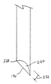
図1を参照すると、少なくとも1つの実施例によるポータブルデバイス100が示される。デバイス100は、物質のサンプルにおける関連する分析物の存在を検出することで、対象有機分子(例えば、アレルゲン)について、液体及び/または固体物質(例えば、食物などの消耗可能な産物)をテストするポータブルデバイスである。デバイス100の可搬性により、ユーザはデバイス100を、例えば、レストラン、パーティなどに持ち運ぶことができ、サンプル(例えば、食物)を即座に(例えば、実質的に、即座に)使用する前に(例えば、消費する前に)テストすることができる。食物及び食物アレルギーのコンテキストにおいて、ソーシャルアクティビティに関連し、通常であれば避ける食物を消費することによる過酷なアレルギーの負担からユーザを解放する。ほぼ即座に行われるテストにより、食物テストは、より目立たなくなり、アレルギーに関連する汚名のいくつかを除去することができる。
With reference to FIG. 1, a
デバイス100は、テストチャンバ108、光源112及び光センサ116を含む本体(即ち、筐体)104を含む。プローブ120によれば、ユーザは、サンプルを収集し、光源112及び光センサ116を使用するテストのために、テストチャンバ108にサンプルを配置することができる。バッテリ122は光源112及び光センサ116に電力を供給する。いくつかの場合において、デバイス100は、光センサ116からの読み出しを受信し、配置されたサンプルに対象有機物質に関連する分析物が存在するか否かを評価するプロセッサ124を含む。代替的に、もしくは、追加的に、プロセッサ124は、分析のために光センサ116からコンピューティングデバイス(例えば、スマートフォン)に読み出しを(無線で、または、有線で)伝達する。デバイス100はテスト結果を示すよう制御可能であるディスプレイ128を含んでいてもよい。
The
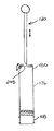
図2及び図3を参照すると、ポータブルデバイス100は、テストチャンバ108を含む取り外し可能なカートリッジ132を含む。テストチャンバ108は、分析試薬を含むテスト試液136及び突き刺し可能膜壁140を含む。カートリッジ132は、取り外し可能に、本体104の収容キャビティ144に挿入可能である。これにより、テストチャンバ108は、光源112から光放射を受け取り、光センサ116に光放射を出射するように位置合わせされる。
With reference to FIGS. 2 and 3, the
プローブ120は、産物148(例えば、食物)に突き刺され、プローブ120上、または、プローブ120内に、液体及び/または固体食物サンプルを収集し、プローブ120は、さらに、膜壁140を突き刺すために使用される。これにより、プローブ120のサンプル152はテスト混合物154を生成するために試液136と混合される。光源112は、1つもしくは複数の第1波長(例えば、250nm)をもつ光放射でテスト混合物154を照射し、光センサ116は対象有機物質(例えば、アレルゲン)に関連する分析物の存在を示す1つもしくは複数の第2波長(例えば、450nm)をもつ光放射を検出する。光センサ116からの読み出しが評価され、サンプル152が分析物を含むか否か判定され、結果がディスプレイ128に表示される。カートリッジ132が廃棄され、次のテストのために新しいカートリッジで置き替えられる。
The
以下の実施例において、物質148は食物(消費可能な産物)として説明され、サンプル152は食物サンプルとして説明される。しかしながら、薬、有機化合物、たんぱく質、及び他の細胞物質などの他の液体及び/または固体物質で、本実施例のポータブルデバイス100が使用されてもよい。以下のいくつかの実施例のポータブルデバイス100は、アレルゲンを検出する例によって説明される。しかしながら、薬、特定のアレルゲンまたは食物感受性の他のトリガー、細菌性副産物、診断による特定分析物、がんマーカ、及び他の細胞物質などの他の有機分子を検出するために使用されてもよい。
In the following examples,
光源112は、光放射を射出する刺激源の例であり、光センサ116は光放射を検出するセンサの例である。他の実施例において、光源112及び光センサ116は、例えば、磁場もしくは電気特性を検知する一つもしくは複数の他の検知システムによって置き替えられてもよいし、補われてもよい。
The
図3Cは、磁気検知システムを含むポータブルデバイス100bの実施例を示す。ポータブルデバイス100bは、刺激コイル112b及び磁場検知ワイヤ116bの形態の磁場刺激ワイヤ(「刺激源」)をもつ。刺激コイル112bはテストチャンバ108bの周囲に巻かれ得る。検知ワイヤ116bは、テストチャンバを通過し得、例えば、コンジットに検知ワイヤを配置することで、もしくは、シースで検知ワイヤを覆うことで、一般的に、テスト混合物と電気的に絶縁される。デバイス100bにおいて、検知ワイヤ116bは筐体コンタクト126b及びカートリッジコンタクト127bによって、コンダクタ123bと接続される。コンダクタ122bはプロセッサ124bと接続される。コンダクタ122bは、アナログデジタルコンバータなどの信号プロセッサ129を介して接続されてもよい。検知ワイヤ116bは、コイルの形態であってもよい。より一般的には、何れかの方法で、刺激ワイヤ及び検知ワイヤが形成され、配置されることで、テストチャンバの内容の磁気特性の変化が検知される。ポータブルデバイス100bにおいて、刺激コイル112bの電流の形態で刺激信号を適用することで、磁場がテストチャンバ108bで誘導される。磁場は、検知ワイヤ116bに電流を誘導する。刺激コイル112bと検知ワイヤ116bとの磁気結合は、テストチャンバの内容の(誘電特性または透磁性などの)磁気特性または当該内容に依存して変動し、電圧または電流の変化として計測し得る、検知ワイヤ116bに誘導される信号の変化をもたらす。プロセッサ124は、検知ワイヤ116bの信号計測に対応する読み出しを受信し、検出した磁場または磁場の変動(静的または時間的なパターン)がテスト混合物における対象分析物の存在を示すか否かを判定する。
FIG. 3C shows an example of a portable device 100b including a magnetic detection system. The portable device 100b has a magnetic field stimulation wire (“stimulation source”) in the form of a stimulation coil 112b and a magnetic field detection wire 116b. The stimulating coil 112b can be wound around the
図3Dは、プレート118a及び118bをもつ電気センサ116cを含む伝記検知システムを含むポータブルデバイス100cの実施例を示す。プレート118は、収容キャビティ144cの壁面または内部に隣接して配置され得る。テストチャンバ108cの内容のキャパシタンス、リアクタンス、または抵抗などの電気特性の変化は、プレート118の間で計測され得る。リムーバブルカートリッジ132cを使用するいくつかの実施例において、プレート118は、テストチャンバ108c内に導入され、本体104c内で、コンダクタ126cと電気的に接続され得る。電気検知システムは、刺激なしで、電気センサ116cを使用して、電気特性を、受動的に、検出し得る。代替的に、電気検知システムは、テストチャンバの内容をわたる電流または電場を適用する刺激源112cを含み得る。プロセッサ124は、電気センサ116cからの読み出しを受信し、検出された電気特性または電気特性の変化(静的または時間的なパターン)がテスト混合物における対象分析物の存在を示すか否か判定する。
FIG. 3D shows an embodiment of a portable device 100c that includes a biography detection system that includes an
図1、3C、及び3Dを参照するいくつかの実施例において、ポータブルデバイス100は2つもしくは複数の検知システムを含み得る。これにより、ポータブルデバイス100は、光放射、磁場、もしくは電気特性などの検出された特性の2つ以上の組み合わせを参照して、分析物の存在を判定することができるので、いくつかの分析物の検出が可能となるか、もしくは改善される。
In some embodiments with reference to FIGS. 1, 3C, and 3D, the
図3に示されるバッテリ122は、光源112、光センサ116、プロセッサ124、及びディスプレイ128などのポータブルデバイス100の一つもしくは複数のエネルギー消費コンポーネントに電力を供給するのに適した、一つもしくは複数のエネルギー蓄積デバイスであってよい。例えば、バッテリ122は、アルカリ、Ni−CAD、NiMHもしくは、Liイオンバッテリであってよく、充電可能なバッテリであってもよいし、一度使用すると廃棄するバッテリであってもよい。好ましくは、バッテリ122は、ポータブルデバイス100の可搬性を促進するように、小さい形態を有する。例えば、バッテリ122は、一つもしくは複数の単3、単4、単2、単1、9V形、CR−V3、CR−2032、もしくはポータブル家電(例えば、カメラ、スマートフォン、リモコンなど)で通常見られるタイプの電池と同様のサイズの電池であってよい。
The
ポータブルデバイス100は、液体の分析試薬を保存するのに適したいずれかのテストチャンバ108を含む。これにより、分析試薬と混合する食物サンプルを置くことができ、テストチャンバの食物サンプルと分析試薬とのテスト混合物の光学テストが可能となる。例において、テストチャンバ108は、試液136を含む内部容積160を画定する一つもしくは複数のチャンバ壁156を含む。少なくとも1つの壁140は、テストチャンバ108に食物サンプルを置くために、プローブ120によって突き刺し可能な膜によって形成される。テストチャンバ108は、示されるような直方体、もしくは他の規則的なまたは不規則な形状であってよい。例えば、テストチャンバ108は、医薬用ブリスターパックと同様な、突き刺し可能な壁140によってシールされる丸みのある(例えば、半球状の)チャンバ壁156を有していてもよい。チャンバ壁156の各々は硬くてもよいし、曲げが可能であってもよい。例えば、チャンバ壁156の全ては硬く、膜壁140を除いて、突き刺しに実質的に対抗してもよい。膜壁140は曲げが可能であり、突き刺しを許容する。これにより、テストチャンバ108は、照射及び光検出のための予測可能な形状を有することができる。
The
1つもしくは複数のチャンバ壁156の少なくとも部分は透明または半透明であってよく、内部のテスト混合物154の照射及び対象有機分子(例えば、アレルゲン)と関連する対象分析物の光検出を可能とする。例において、チャンバ壁156は照射窓164及びセンサ窓168を含む。照射窓164及びセンサ窓168の各々は、少なくとも部分的に透明であり、これにより、少なくとも対象波長の光放射がテストチャンバ108に入出することを可能とする。いくつかの実施例において、照射窓164及びセンサ窓168の一方または双方は、光フィルタを有し、テストプロトコルに従って、所定の光放射波長の通過を遮蔽する。例えば、テストプロトコルは、第1波長を有する光放射でテスト混合物154を照射すること、及び、食物サンプル152における対象分析物の存在を示す第2波長を有する光放射を検出することを含み得る。この場合、光源112が、追加的に、第2波長で光放射を射出する場合、照射窓164は光フィルタ172を有し、第2波長の光放射を遮蔽してもよい。これにより、テスト混合物154を介するのではなく、光源112により射出される光放射を直接検出することで生じる誤った肯定を回避する支援となる。他の実施例では、光フィルタ172は、光源112とテストチャンバ108との間で本体104に形成されてもよい。例えば、収容キャビティ144の部分は、照射窓164の代わりに、もしくは、加えて、光フィルタ172を含んでいてもよい。
At least a portion of one or
照射窓164及びセンサ窓168は、図1に示されるように、別個であり、チャンバ壁156と離れていてもよいし、接触していてもよいし、重複していてもよいし、隣接していてもよい。例において、センサ窓168は、照射窓164と反対側に位置し、対向している。これにより、照射窓164を通りテストチャンバ108に向かう光放射は、センサ窓168に、テスト混合物154内部を通り、直接向かう。これにより、センサ窓168に向かって、テストチャンバ108を通過する光放射の減衰を低減することで、光センサ116の感度を改善し得る。代替的な実施例において、センサ窓168及び照射窓164は、相互に対向せず、テストプロトコルにしたがって光センサ116に向かう、光源112からの光放射の直接的な通過が妨げられてもよい。例えば、センサ窓168は、照射窓164と実質的に直交する向きであってもよい。他の実施例において、センサ窓168及び照射窓164は、まったく同一であり、これにより、光源112はテストチャンバ108を照射し、光センサ116は、同じウィンドウ164、168を通る、テストチャンバ108からの照射を検出する。
The irradiation window 164 and the sensor window 168 are separate, may be separated from, may be in contact with, may be in contact with, may overlap, or be adjacent to the
図3Bは、複数の光源112を含むデバイス100の実施例を示し、光源112の各々は、テストチャンバ108の異なる側面からテストチャンバ108に光放射が向かうように配置される。例えば、光源112は、反対側のテストチャンバ壁156を通り、テストチャンバ108へ到達するように光を向ける。異なる方向からテストチャンバ108を照射する複数の光源112を備えることで、高価でないより小さい光源112を使用することができ、光源112により射出される光放射からテスト混合物154の部分が隠れる確率を低減することができ、光射出へのテスト混合物の露出量をより均一にすることができる。示されるように、光センサ116は、光源112に対してある(ゼロではない)角度で向けられている。例えば、光センサ116は、例示されるように、光源112と実質的に直交していてもよい。
FIG. 3B shows an example of a
テストチャンバ壁156のいくつかまたは全ては、照射窓164及びセンサ窓168を除いて、もしくは窓164、168及び突き刺し可能な膜壁140を除いて、部分的に、または完全に不透明であってよい。例えば、テストチャンバ壁156の全ては、照射窓164及びセンサ窓168を除いて、または、ウィンドウ164、168及び突き刺し可能膜壁140を除いて、光放射の全ての波長、光放射の全ての(人間の)可視波長、または、テストプロトコルによって使用される光放射の全ての波長(例えば、第1入力波長)に対して不透明であってよい。他の実施例において、テストチャンバ156は実質的に透明であってよい(例えば、透明度を制限または変化させる目的で適用される何れかの処理またはフィルタリングなしに、透明プラスチックまたは透明ガラスなどの、選択されたマテリアルの基本的な特性によって透明であってよい)し、テストプロトコルによって使用される光放射の全ての波長(例えば、第1入力波長及び第2入力波長)に対して実質的に透明であってよい。
Some or all of the
テストチャンバ108は、図1に示されるように、ポータブルデバイス100に持続的に接続されていてもよい。この場合、ポータブルデバイス100は、使い捨てデバイスであってよく、テストチャンバ108の数と同じ回数だけ使用可能であってよい。代替的に、テストチャンバ108は、図2及び図3に示されるように、カートリッジ132に含まれてもよく、カートリッジ132は、デバイスの本体104の収容キャビティ144で取り外し可能であり、受け取り可能である。これにより、ポータブルデバイス100からカートリッジ132を取り外すことができ、廃棄することができ、次のテストのために、収容キャビティ144に新しいカートリッジ132を挿入することができる。この場合、ポータブルデバイス100は、他のデバイスコンポーネント(例えば、光源112、光センサ116、バッテリ122)が生存している間、実質的に無制限にテストを実行するように操作されてもよい。テストチャンバ108と同様に、他のデバイスコンポーネントの各々は、取り外しできないように本体100に持続的に取り付けられていてもよいし、必要に応じて置き換えられるように取り外しできてもよい。
The
図1及び図4を参照するいくつかの実施例において、カートリッジ132または本体104は、入口通路176を有していてもよい。入口通路176はプローブ120のためのストレージを提供してもよく、テストチャンバ108への環境光を遮蔽するよう支援してもよいし、双方であってもよい。示されるように、入口通路176はアップストリーム端180及びダウンストリーム端184を含む。アップストリーム端180は、プローブ120の少なくとも部分を通過させるプローブ開口188を含む。ダウンストリーム端184は、テストチャンバ108の突き刺し可能な膜壁140を含む。入口通路176は、任意のサイズ及び形状を有し得る。例えば、入口通路176は、示されるように、直方体であってもよいし、規則的なまたは不規則な任意の他の形状を有していてもよい。入口通路176は、示されるように、テストチャンバ108より(容積、または、1つもしくは複数の寸法が)大きくてもよいし、テストチャンバ108と同じサイズであってもよいし、テストチャンバ108より小さくてもよい。
In some embodiments with reference to FIGS. 1 and 4, the
図4Bを参照すると、いくつかの実施例において、カートリッジ132は入口通路176を有さない。例えば、カートリッジ132は、試液136の分析試薬と混合するように、テストチャンバ内部容積160にサンプルを配置するように、プローブによって突き刺される外部に露出された膜壁140をもつテストチャンバ108を含み得る(図3C〜図3D)。これにより、カートリッジ132及び収容キャビティを小さくすることで、ポータブルデバイスの可搬性を強めることができる。
Referring to FIG. 4B, in some embodiments, the
図4Cを参照すると、実施例のいくつかにおいて、カートリッジ132は、突き刺し可能な膜壁140で分割された、2つ以上のサブチャンバ110をもつテストチャンバ108を含む。例において、テストチャンバ108は、3つのサブチャンバ110を含み、サブチャンバ110の各々の上端は突き刺し可能な膜壁140を含む。示されるように、サブチャンバ110は、プローブが、単一の動きで、サブチャンバ110の全ての膜壁140を突き刺すことができるように、直列に配置されてもよい。サブチャンバ110の各々は、サブチャンバの内容111を含み得る。サブチャンバ110の2つ以上の内容は、合わせて、試液を形成してもよい。例えば、複数のサブチャンバ111の内容111は、プローブで膜壁140を突き刺すと、(例えば、最下層のサブチャンバ110cで)混合されてもよい。内容111a、111b及び111cの混合物は、試液を形成してもよい。
Referring to FIG. 4C, in some of the embodiments, the
異なるサブチャンバ110の内容111は異なっていてもよい。実施例のいくつかにおいて、2つ以上のサブチャンバの内容111は、1つもしくは複数の異なる分析試薬を含んでいてもよい。例えば、内容111aは、1つもしくは複数の第1分析試薬を含み、内容111bは1つもしくは複数の第2分析試薬を含んでいてもよい。実施例のいくつかにおいて、サブチャンバの内容111の1つもしくは複数は、テスト混合物の分析試薬が対象分析物をより利用しやすくなる抽出液を含んでいてもよい。例えば、抽出液は、食物サンプルの対象分析物を入れる、または、食物サンプルに付着した脂肪を分解する、または、結合を乖離するように作用し、これにより、分析試薬は、対象分析物と反応するようによりよくアクセスする。実施例のいくつかにおいて、1つもしくは複数のサブチャンバの内容111は、所望されない分子と結合するようにつくられている保護液を含むことができ、これにより、これらの所望されない分子は、分析物の代わりに、分析試薬と反応しない。
The contents 111 of the different subchambers 110 may be different. In some of the examples, the content 111 of the two or more subchambers may contain one or more different analytical reagents. For example, the
実施例のいくつかにおいて、分析試薬の成分は、2つ以上のサブチャンバの内容111の間で分割されてもよい。例えば、1つのサブチャンバの内容111は、脱水分析試薬を含み、他のサブチャンバの内容111は、水和(例えば、水)を含み得る。これにより、2つのサブチャンバの内容111が混合されると、完全な分析試薬を形成し得る。いくつかの場合、これにより、カートリッジ132の貯蔵寿命が改善され得る。
In some of the examples, the components of the analytical reagents may be split between the contents 111 of the two or more subchambers. For example, the content 111 of one subchamber may contain dehydration analysis reagents and the content 111 of the other subchamber may contain hydration (eg, water). Thereby, when the contents 111 of the two subchambers are mixed, a complete analytical reagent can be formed. In some cases, this can improve the shelf life of the
図4を参照すると、テストチャンバ108は、有機分子物質(例えば、アレルゲン)を示す分析物の存在をテストするのに適した液体試液136に任意の液体分析試薬を含んでいてもよい。例えば、分析試薬136は、対象分析物(例えば、ピーナッツアレルゲンを示すピーナッツ1)と反応する(例えば、結合する)化合物の1つもしくは複数を含むことができ、これにより、光、磁気及び/または電気特性の変化を生じる。いくつかの例において、光、磁気及び/または電気特性は、例えば、光放射または磁場に、テスト混合物を露出し得る刺激源により刺激され得る。例えば、テスト混合物は、蛍光の増減であってよい光で検出可能な変化を明らかにしてもよい。この場合、テスト混合物154(図3)は、射出し、射出を低減し、もしくは、第2の波長と異なる、1つもしくは複数の第1波長の光放射による照射が行われると、1つもしくは複数の第2波長の光放射の射出が停止される。結合反応及びこれにより生成される蛍光の特性に依存して、1つもしくは複数の第2波長は、1つもしくは複数の第1波長より長くてもよい。射出される光放射は、照射光放射よりもエネルギーが小さい。実施例のいくつかにおいて、検出可能な変化は、光、磁気または電気特性の時間的パターンを含み得る。例えば、光で検出可能な変化は、1つもしくは複数の第3波長の次の射出が続く1つもしくは複数の第2波長の初期射出を含み得る。これは、テスト混合物に発生する連続的な反応を示してもよいし、分析物の存在を示してもよい。
With reference to FIG. 4, the
好ましくは、テストチャンバ108は、極めて小さい内部容積160を含み、これにより、試液136を含む分析試薬の極めて小さい量を含む。これにより、ポータブルデバイス100の可搬性が促進される。ポータブルデバイス100は、部分的に、分析物の濃度(即ち、アレルギーによって人間で反応する原因となる十分なアレルゲン、LOAELもしくは最低観察逆効果レベルとして参照されることがある、の存在を示すのに十分有意な濃度)が低いか、もしくは、臨床的に有意であることを検出することができる。テスト(例えば、光照射及び検出、磁場生成及び磁気特性検出、及び/または、電気特性検出)が、ダウンストリーム(例えば、テストストリップで)の代わりに、テストチャンバ108のテスト混合物154(図3)で実行されるためである。臨床的に有意な濃度を詳細に含むものは、分析物と対象有機分子(例えば、アレルゲン)と、特定の対象有機分子との間の関係(例えば、ピーナッツアレルゲン対甲殻類アレルゲン)に依存する。いくつかの例において、テストチャンバ108は、1μL〜250μLの試液など、約250μLより少ない試液を含む。テストチャンバ内部容積160は、分析試薬の容積よりも多い容積をもち、1μL〜1mLなどの1mLより少ない容積を含み得る。
Preferably, the
図5を参照すると、試液136の小さい液体容量及びテストチャンバ内部容積160の小さいサイズにより、ポータブルデバイス本体140もしくはカートリッジ132に複数のテストチャンバ108を入れても、ポータブルデバイス100の可搬性を維持することができる。いくつかの例において、デバイス本体104またはカートリッジ132は、2〜150のテストチャンバ108を含み得る。例において、ポータブルデバイス100は、本体104と統合され、または、カートリッジ132の部分として取り外し可能な、4つのテストチャンバ108を含む。示されるように、テストチャンバ108は、ポータブルデバイス100と相対的に移動可能であり、先行するテストチャンバ108aが使用された後、光源112及び光センサ116と、先行するテストチャンバ108bと、を位置合わせする。代替的に、光源112及び光センサ116は、テストチャンバ108と相対的に移動可能であるか、先行するテストチャンバ108aが使用された後、先行するテストチャンバ108bに向けて、選択的に検出可能であってよい。
Referring to FIG. 5, due to the small liquid volume of the
実施例のいくつかにおいて、ポータブルデバイス100は複数のプローブ120を含んでいてもよい。例えば、ポータブルデバイス100は、本体104またはカートリッジ132にテストチャンバ108の各々のプローブ120を含んでいてもよい。図4に例示されるように、入口通路176は、各々のプローブ120のストレージのためのテストチャンバ108の各々に接続されてもよい。これにより、テスト間の汚染を最小化するために、プローブ120を、一回限りの使用で使い捨てとすることができる。図5Bを参照すると、いくつかの実施例において、ポータブルデバイス100は、本体104またはカートリッジ132のテストチャンバ108の数よりプローブ120の数を少なくしてもよい。例えば、ハンドヘルド100は再使用可能なプローブ120を1つだけ含んでいてもよい。示されるように、本体104またはカートリッジ132は、複数のテストチャンバ108及び複数のクリーニングチャンバ109を含み、これらは、交互に連続的に配置されてもよい。クリーニングチャンバ109は、洗浄液(例えば、イソプロピルアルコール及び水)を含むことを除いて、テストチャンバ108と同じであってよい。使用の際、ユーザは、プローブ120を使用してサンプリングし、第1テストチャンバ108aを使用してテストしてもよい。その後、ユーザはクリーニングチャンバ109を突き刺し、洗浄液とプローブ120で接触し、同じプローブ120で次のテストを行う前に、プローブ120の汚れを落とす。再使用可能プローブ120により、よりコンパクトで、複数回使用できる、ポータブルデバイス100が可能となる。
In some of the examples, the
図5Cは、複数のテストチャンバ108を含むカートリッジ132の例を示す。示されるように、テストチャンバ108の各々は、チャンバ壁156及び突き刺し可能な膜壁140を含み、これらは、試液136を含むチャンバ内部容積160を画定する。図5Dは、複数のテストチャンバ108及び複数のクリーニングチャンバ109を含むカートリッジ132の例を示す。示されるように、テストチャンバ108は、クリーニングチャンバ109と交互に直列に配置されていてもよい。クリーニングチャンバ109の各々は、チャンバ壁156及び突き刺し可能な膜壁140を含み、洗浄液137を含むチャンバ内部容積160を画定する。
FIG. 5C shows an example of a
図4Dを参照すると、いくつかの実施例において、クリーニングチャンバ109は、突き刺し可能膜壁140によって分割された2つ以上のサブチャンバ110を有していてもよい。例において、クリーニングチャンバ109は、3つのサブチャンバ110を含み、サブチャンバ110の各々の上端は突き刺し可能膜壁140を含む。示されるように、サブチャンバ110は、プローブが、単一の動きで、サブチャンバ110の全ての膜壁140を突き刺すことができるように、直列に配置されていてもよい。サブチャンバ110の各々は、サブチャンバの内容111を含んでいてもよい。2つ以上のサブチャンバ110の内容111は、混ぜ合わせることで洗浄液を形成してもよい。例えば、内容111aは水を含み、内容111bはイソプロピルアルコールを含み、プローブで突き刺されることで混合し、洗浄液を形成してもよい。
With reference to FIG. 4D, in some embodiments, the
図3を参照すると、光源112は、テストプロトコルによって必要とされる十分な強度の1つもしくは複数の第1の波長をもつ光放射を射出するのに適した任意のデバイスであってよい。例えば、光源112は、LED光、白熱光、ハロゲン光、レーザ光、または、これらの組み合わせを含み、テストプロトコルによって必要とされる1つもしくは複数の第1波長を少なくとも含む光放射を射出するように構成されている。いくつかの場合、光源112は、追加的に、テストプロトコルによって必要とされる波長以外の外来の1つもしくは複数の波長をもつ光放射を射出してもよい。この外来の光放射が所望されない場合(例えば、テストの品質に負の影響を与える場合)、照射窓164はフィルタ172を含み、1つもしくは複数の第1波長をもつ光放射は通過することができるが、外来の光放射は遮断されてもよい。
With reference to FIG. 3, the
光センサ116は、テストプロトコルによって必要とされる十分な感度をもつ1つもしくは複数の第2波長をもつ光放射を検出するのに適した任意のデバイスであってよい。いくつかの場合、光センサ116は、追加的に、テストプロトコルによって必要とされる波長以外の1つもしくは複数の波長をもつ異質の光放射を検出してもよい。この異質の光放射を検出することが所望されない場合(例えば、テストの品質に負の影響を与える場合)、センサ窓168は光フィルタ189を含み、1つもしくは複数の第2波長をもつ光放射は通過させるが、異質の光放射は遮蔽される。他の実施例において、光フィルタ189は、光センサ116とテストチャンバ108との間の本体104に形成されてもよい。例えば、収容キャビティ144の部分は、センサ窓168の代わりに、または、センサ窓168に加えて、光フィルタ189を含んでいてもよい。
The
ディスプレイ128は、テストの結果を視覚的に示すのに適した任意のデバイスであってよい。例えば、ディスプレイ128は、光(例えば、LED,白熱、ハロゲンなど)、LCD画面、LED画面、eインクディスプレイ、OLEDディスプレイ、または、これらの組み合わせを含んでいてもよい。ディスプレイ128は、ユーザインタラクティブな(例えば、メニューまたは機能選択)タッチスクリーンディスプレイまたは非タッチスクリーンディスプレイであってよい。例において、ディスプレイ128は、選択的に照射可能な(例えば、プロセッサ124によって)2つのLED190を含み、対象有機物質(例えば、アレルゲン)を示す分析物(または分析物の濃度閾値)が食物サンプルで発見されたか否かを伝達する。他の実施例において、ディスプレイ128は、検出された分析物の識別、検出された分析物と関連する対象有機物質の識別、及びサンプルの分析物の濃度など、他の情報を伝達してもよい。実施例のいくつかにおいて、ポータブルデバイス100はディスプレイ128を含まない。例えば、ポータブルデバイス100は、無線で、もしくは、有線で、テストの結果を提示する他のデバイス(例えば、スマートフォン)に伝達してもよい。
The
図2を参照すると、プローブ120は、食物サンプルを収集するために食物を突き刺すのに適し、分析試薬を含む液体試液136に収集された食物サンプルを配置するために、テストチャンバ膜壁を突き刺すのに適した任意のデバイスであってよい。実施例において、プローブ120は遠位端196及び近位端200をもつ延在するプローブシャフト192を含む。示されるように、プローブシャフト遠位端196は食物サンプルを収集するために食物を突き刺し、収集した食物サンプルを配置するためにテストチャンバ膜壁140を突き刺すために、尖っていてもよい。必須ではないが、プローブ120は、さらに、ユーザのためのマニュアル把持面を提供し、プローブシャフト近位端200に接続されるハンドル204を含んでいてもよい。
Referring to FIG. 2,
プローブシャフト192は、食物を突き刺し、突き刺された食物から食物サンプルを収集し、テストチャンバ膜壁140を突き刺すのに適した任意のマテリアルで形成されていてもよい。好ましくは、プローブシャフト192は、食物及びテストチャンバ膜壁140を突き刺したときに、曲がらないように十分な硬さをもつ。例えば、プローブシャフト192は、木、金属、プラスチック、セラミックまたはガラスで形成されていてもよい。ポータブルデバイス100は、サンプリングされた食物に基づいて、選択された異なる複数のプローブ120を含んでいてもよいし、対応していてもよい。例えば、多孔性のマテリアル(例えば、木)を含むプローブシャフト192をもつプローブは、試液及び食物に含まれる液体によく適している。
The
プローブシャフト192(またはその部分)は、1つもしくは複数の面特徴を含み、様々なタイプの食物からの食物のサンプルの取得またはサンプリングを容易にする。面特徴は、マテリアルによって当然に提供されてもよいし、物理的または化学的手段によって与えられてもよい。図6を参照すると、いくつかの実施例において、プローブシャフト192の少なくとも部分は、複数のピット208があってもよい。ピット208は、基盤マテリアルから得られてもよいし、化学的処理(例えば、酸処理)または、物理的処理(例えば、レーザによる穿孔)によって与えられてもよい。ピット208は、プローブシャフト192での食物サンプルの収集を容易にするのに適した任意のサイズであってよい。例えば、ピット208は、25μm〜250μmの最大寸法212を有し、プローブシャフト192は10以上のピット208(例えば、10〜5000のピット208)を有していてもよい。使用する際に、ピット端216は、食物サンプルを落とすように突き刺された食物と擦れるように動作してもよいし、小さい食物サンプルはピット208内に収集されてもよい。
The probe shaft 192 (or portion thereof) includes one or more surface features to facilitate the acquisition or sampling of food samples from various types of food. Surface features may of course be provided by the material or may be provided by physical or chemical means. Referring to FIG. 6, in some embodiments, at least a portion of the
図6Bに戻ると、実施例のいくつかにおいて、プローブシャフト192は1つもしくは複数の面チャネル218を含んでいてもよい。面チャネル218は、プローブシャフト192の面に沿って延在する窪みとして形成されてもよい。例において、面チャネル218は、プローブ192のまわりに、らせん状に延在する。図6Cは、プローブシャフト192のまわりのらせん状のパスに沿って離隔して非連続的な複数の面チャネル218を含む例を示す。
Returning to FIG. 6B, in some of the embodiments, the
図3を参照すると、テストチャンバ108の小さい容量及びその内部の試液136の小さい容量により、大きな食物サンプル220は、食物サンプル220がテストを受けるテストチャンバ108に入ることを妨げられる(例えば、分析試薬を圧倒し、光センサ116の視野を遮蔽し、光源112からの光放射を遮蔽する)。膜壁140は、テストチャンバ108に大きいサンプル220が入ることを妨げる機械的なフィルタとして作用してもよい。プローブシャフト192がテストチャンバ膜壁140を貫通すると、膜壁140はプローブシャフト192に沿って拭うように作用し、これにより、テストチャンバ108に大きい食物サンプル220が入ることを妨げる。しかしながら、例えば、ピット208(図6)に含まれる小さい粒子は通過することができる。したがって、ピット208のサイズ及び数は、テストチャンバ108に配置される食物サンプルのサイズ及び量を規定する支援となり得る。
Referring to FIG. 3, the small volume of
図7を参照すると、実施例のいくつかにおいて、プローブシャフト遠位端196はキャビティ(即ち、窪み部)224を有していてもよい。示されるように、キャビティ224は、中央に位置し、シャフト遠位端196の周辺228によって画定される。ピット208(図6)と同様に、キャビティ224は、食物をサンプリングする間、食物サンプル152(図3)を収集し、膜壁140を突き刺している間、落とさない窪みを提供してもよい。キャビティ224は、小さい食物サンプル152を収集するのに適した任意の深さ232を有していてもよい(図3)。例えば、キャビティ深さ232は、25μm〜2500μmであってよい。
Referring to FIG. 7, in some of the embodiments, the probe shaft
図8を参照すると、実施例のいくつかにおいて、プローブシャフト192の少なくとも部分は、研磨突出236を有していてもよい。研磨突出236は、ナッツなどの硬い食物から小さい食物サンプル152(図3)をはずす、または削り取るのを支援してもよい。研磨突出236は、プローブシャフト192に食物サンプル152(図3)を保持するのを支援してもよい。これにより、小さい食物サンプル152(図3)は、膜壁140を突き刺したときに落とされないように抵抗する。研磨突出236は、硬い食物から小さい食物152(図3)をはずすのに、及び/または、食物サンプル152に保持するのに、適した任意の突出高さ240を有していてもよい。例えば、突出高さ240は25μm〜250μmであり、プローブシャフト192は10以上の突出236(例えば、10〜5000の突出236)を有していてもよい。突出236は、基盤マテリアルから当然に生じてもよいし、また、粒子の粗いコーティングでプローブシャフト192をスプレーすることなどで、プローブシャフト192に適用されてもよい。図6〜図8は、プローブシャフト面特徴の様々な例を示す。いくつかの実施例において、これらの特徴が組み合わせられてもよい。例えば、プローブシャフト192は、上記特徴(例えば、多孔、ピット、面、遠位端キャビティ、及び、研磨突出)の1つもしくは複数(もしくは全て)を含んでいてもよい。
Referring to FIG. 8, in some of the examples, at least a portion of the
テストチャンバ108を突き刺すと、プローブシャフト192の少なくとも部分は、試液136に浸され、もしくは、少なくとも接触する。これにより、プローブシャフト192に収集された食物サンプルはテスト混合物154に放たれる。実施例のいくつかにおいて、撹拌は、プローブシャフト192から試液136に食物サンプルが落とされるのを容易とし、試液136及び食物サンプルの分析物(分析物が存在する場合)との間の反応を加速してもよい。図3を参照すると、撹拌は、ポータブルデバイス100を振ることで(例えば、プローブシャフトが膜壁140を貫通する間)行われ、または、プローブ120を振ることで(例えば、プローブ120を、繰り返し、テストチャンバ108に入れたり、テストチャンバ108から出したりすることで)行われてもよい。代替的に、または、加えて、ポータブルデバイス100は、テストチャンバ108または装置100を全体的に振動させるように動作する撹拌手段または振動手段280を含んでいてもよい。
When the
図3を参照すると、テストプロトコルに依存して、テスト前、テスト中、もしくは、検知中に、光、空気、磁気、熱、及び湿気などの汚染がテストチャンバ108に入るのを妨げる必要があり得る。これは、例えば、テストプロトコルにより使用される光放射(例えば、入力第1波長または出力第2波長をもつ光放射)が環境光(例えば、日光または従来の室内光)で通常検出される場合である。例において、入口通路176は、プローブシャフト192を収納するサイズをもつ狭いプローブ開口188を含む。これにより、プローブシャフト192は、実質的に、プローブ開口188を通してテストチャンバ108への、光、空気、熱、及び湿気の1つもしくは複数(または全て)を低減し、もしくは、抑制してもよい。代替的に、もしくは、狭いプローブ開口188に加えて、プローブ120は、少なくともプローブ開口188をカバーするサイズである、プローブシャフト近位端200にフランジ244を含んでいてもよい。示されるように、プローブフランジ244は、プローブハンドル204(存在する場合)の部分を形成してもよいし、プローブハンドル204とは別個の構成要素であってもよい。プローブフランジ244は、本体104及び/またはカートリッジ132によるシールを形成してもよい。例えば、プローブフランジ244、本体104及び/またはカートリッジ132は、1つもしくは複数のシール246を含み、光、空気、磁気、熱及び湿気の1つもしくは複数の受け入れキャビティ144及び/またはテストチャンバ108への侵入を実質的に低減し、抑制するように、プローブフランジ244と係合する。実施例のいくつかにおいて、本体104の少なくとも部分が、光、空気、磁気、熱及び/または湿気の1つもしくは複数(または全て)の侵入をシールされる。
Referring to FIG. 3, depending on the test protocol, contamination such as light, air, magnetism, heat, and moisture should be prevented from entering the
図9及び図10は、ドア248を含む入口通路176の例を示す。示されるように、入口通路ドア248は、ドア248がテストチャンバ108への環境光の侵入を遮蔽する閉位置(図9)、及び、ドア248がテストチャンバ108にプローブ120の侵入を許可する開位置(図10)を含む。入口通路ドア248は、テストチャンバ108から取り除かれるプローブ120により実行されるテストを許容し、これにより、プローブ120はテストと干渉しない(例えば、光センサの視野を遮蔽する)。ドア248は、示されるように、アップストリーム端180などで、入口通路176に沿った任意の位置に配置されてもよい。必須ではないが、ドア248は、閉位置にバイアスされ(例えば、スプリングにより)、これにより、ドア248はプローブ120が引かれると自動的に閉まる。
9 and 10 show an example of an
図11及び図12は、リトラクタブルプローブシャフト192を含むプローブ120の例を示す。示されるように、プローブシャフト192は、収納位置(図11)と伸長位置(図12)との間のプローブフランジ244と相対的に移動可能である。これにより、プローブフランジ244は、入口通路アップストリーム端180に位置し、プローブシャフト192は、収納位置と伸長位置との間で往復し、プローブシャフト192からテスト混合物154に食物サンプル152を落とし、テスト混合物154を撹拌する。さらに、これにより、プローブシャフト192は、試液136により多く浸かるように、テストチャンバ108に深く伸長される。伸長された位置において、光センサ116の視野を隠すことで、または、光源112によるテスト混合物154の位置のいくつかの照射を隠すことなどで、プローブシャフト192は、テストと干渉してもよい。しかしながら、収納位置において、プローブシャフト192は、テストと干渉しないように、動かされてもよい。実施例のいくつかにおいて、プローブシャフト192は、ユーザがプローブ120を離した際に、プローブ120がテストと干渉しないように、収納位置にバイアスされてもよい。例えば、プローブシャフト192は、スプリング252または他のバイアス部材により収納位置にバイアスされてもよい。
11 and 12 show an example of a
図13及び図14は、ルーメン256及びルーメン256内のリトラクタブルプランジャー260を含むプローブ120の例を示す。示されるように、プランジャー256は、収納位置(図13)及び伸長位置(図14)の間で移動可能である。収納位置において、プランジャー遠位端264は、プローブシャフト遠位端196から収納され、キャビティ224を形成する。図7に関連して上記したように、食物サンプルはキャビティ224に収集され、収集された食物サンプルは、膜壁を突き刺すと、落とされないように抵抗してもよい。この場合、プランジャー260は収納位置から伸長位置まで移動可能であり、テストチャンバに、キャビティ224に収集される食物サンプルを放出する。プランジャー260は、小さい食物サンプルのキャビティ224を提供するのに適した距離までリトラクタブルであってよい。例えば、プランジャー260は25μm〜2500μmの距離までリトラクタブルであってよく、ルーメン256は25μm〜2500μmの直径263を有していてもよい。実施例のいくつかにおいて、プランジャー260は収納位置までバイアスされてもよい。例えば、プローブ120は、収納位置までプランジャー260をバイアスするスプリング268または他のバイアス部材を含んでいてもよい。
13 and 14 show an example of a
プローブ120は、上記したように(例えば、図6〜図14に関連して説明されたように)、プローブ120の特徴の1つもしくは複数(または全て)の何れかを含んでいてもよい。例えば、図16及び図17は、図12及び図13を参照して上記したリトラクタブルプローブシャフト192、図14及び図15を参照して上記したルーメン256のリトラクタブルプランジャー260及びルーメン256をもつプローブシャフト192を含むプローブ120の例を示す。示されるように、プローブシャフト192及びプランジャー260は、収納位置(図15)及び伸長位置(図16)の間で移動可能であってよい。収納位置において、プローブシャフト192は、テストに干渉しないように配置され、伸長位置において、プローブシャフト192はテストチャンバ108内深くに動かされ、プランジャーは、テストチャンバ108に、キャビティ224に含まれる食物サンプル152を放出してもよい。
The
図17は、物質の分析物を検出する方法300のフローチャート例である。実施例のいくつかにおいて、方法300のステップのいくつかは、示されているのとは異なる順序で実行されてもよいし、直列に示されているステップが同時に実行されてもよいし、完全に省略されてもよい。実施例のいくつかにおいて、示されていない追加的なステップが、方法300に含まれていてもよい。
FIG. 17 is an example of a flowchart of the
304で、テストチャンバはポータブルデバイスに挿入される。例えば、図2を参照すると、テストチャンバ108を含むカートリッジ132は、デバイス本体104に形成される収容キャビティ144に挿入されてもよい。図1に示されるように、ポータブルデバイス100が統合テストチャンバ108を含むと、このステップは実行されない。図5に示されるように、ハンドヘルドデバイス100は複数のテストチャンバ108を含む場合、このステップは、シーケンスにおいて次のテストチャンバ108bを進めることで置き替えられてもよい。
At 304, the test chamber is inserted into the portable device. For example, referring to FIG. 2, the
308において、ベースラインテストが実行され、結果が記録される。図1を参照すると、ベースラインテストは、ユーザインターフェイス要素(例えば、ボタン272)のユーザアクティベーションが行われると自動的に、もしくは、デバイス本体104にテストチャンバ108が挿入されると自動的に行われる(図2)。実施例のいくつかにおいて、テストチャンバの試液136の小さい容量により、テストチャンバ108からテストチャンバ108への試液136の正確な容量は相対的に変動してもよい。カートリッジ132を利用するポータブルデバイス100の場合、カートリッジ132のユーザハンドリングは(例えば、照射窓またはセンサ窓の指紋により)テスト結果に影響する可能性がある。あり得る変動のために、食物サンプルが入っていないテストチャンバ108の試液136は、刺激源によって刺激されていない特性(例えば、光、磁気及び/または電気特性)、これらのセンサ(例えば、センサ116、116b、及び/または116c)によって食物サンプルを含む試液でその後実行されるのと同じ方法で検出される特性を有していてもよい。ベースラインテストはその後の比較のために(例えば、プロセッサ124によって)記録される。代替的な実施例において、ベースラインテストの結果は、記録及びその後の比較のために計算処理デバイス(例えば、スマートフォン)に送信される。
At 308, a baseline test is performed and the results are recorded. Referring to FIG. 1, baseline testing is performed automatically when a user interface element (eg, button 272) is user activated, or when the
実施例のいくつかにおいて、テストプロトコルはベースラインテストを必要としない。例えば、入力及び出力射出の性質または分析物を示す検出された射出のパターン(静的なまたは一時的なパターン)は、ベースラインテストが必要とされない十分な一貫性を提供する。取り外しできないテストチャンバを含むポータブルデバイス100の場合、テストチャンバ108のユーザハンドリングを低減することは、ベースラインテストの結果が予測可能となるように、変動を低減してもよい。
In some of the examples, the test protocol does not require baseline testing. For example, detected emission patterns (static or transient patterns) that indicate the nature of input and output injections or analytes provide sufficient consistency without the need for baseline testing. For a
312で、食物サンプルが収集される。図2を参照すると、ユーザはプローブ120を操作し、プローブシャフト192で食物148を突き刺す。好ましくは、ユーザは食物148を複数回突き刺し、食物148の様々な部分からサンプルを収集する。これにより、食物148の所定の部分においてだけ存在する分析物を検出する機会が増大する。
At 312, food samples are collected. With reference to FIG. 2, the user operates the
316で、食物サンプルがテストチャンバに配置される。図3を参照すると、ユーザは、312で取得される食物サンプル152を運ぶプローブ120を操作し、テストチャンバ膜壁140を突き刺す。これにより、テストチャンバ108に少なくともプローブシャフト遠位端196を挿入する。プローブシャフト192で試液136とインタラクションすることで、テストチャンバ108のプローブシャフト192を撹拌することで、試液136を撹拌することで、振動手段280を動作させることで、プローブシャフトプランジャー260を動作させることで(図14)、または、これらを組み合わせることで、食物サンプル152は試液136にプローブ120から放される。
At 316, a food sample is placed in the test chamber. With reference to FIG. 3, the user operates a
320で、テスト混合物が形成される。図3を参照すると、これはテストチャンバ108または試液136を撹拌することを含み、配置された食物サンプル152との反応を加速させる。いくつかの場合において、このステップは、テストチャンバ108への食物サンプル152の配置と重複する。例えば、食物サンプル152を配置するために実行される撹拌は、テスト混合物154を形成するために十分であってもよい。実施例のいくつかにおいて、テスト混合物154は、食物サンプル152と試液136との間の接触を実質的に瞬間に形成し、これにより、食物サンプル152が配置されると、追加的なユーザアクションがテスト混合物154を形成するために必要とされる。
At 320, a test mixture is formed. Referring to FIG. 3, this involves agitating the
324で、テストチャンバのテスト混合物の特性は刺激される(例えば、光源によって照射される、または、磁場に露出される)。図1及び図3を参照すると、刺激源(例えば、光源112または磁場源112b)は、ポータブルデバイス100からプローブ120を引き出したり、プローブ120に入れたりすると自動的に、または、ユーザインターフェイス要素(例えば、ボタン276)のユーザアクティベーションを行うと、アクティブにされる。刺激源112及び/または112bは、テストチャンバ108を露出し、テスト混合物154の光、磁気または電気特性を刺激するように、光放射、または磁場にテストチャンバ108を露出する。
At 324, the properties of the test mixture in the test chamber are stimulated (eg, irradiated by a light source or exposed to a magnetic field). Referring to FIGS. 1 and 3, the stimulus source (eg,
328で、センサは、テスト混合物の特性を検出する。図1、図3C及び図3Dを参照すると、光センサ116、磁場検出手段116b、及び/または電気センサ116cは、テストプロトコルにしたがって、光、磁気及び/または電気特性を検出する。328の検出は、324の刺激と重複し、324の刺激が停止されると開始される。図3Dの実施例において、328の検出は324の刺激なしに行われてもよい。センサ116、116b及び/または116cからの読み出しは、分析のために、プロセッサ124、または、計算処理デバイス(例えば、スマートフォン)に送信される。
At 328, the sensor detects the properties of the test mixture. With reference to FIGS. 1, 3C and 3D, the
332で、328で使用される読み出しは、デルタを決定するために、以前のベースラインテストと比較される。図1、図3C及び図3Dを参照すると、プロセッサ124は、読み出しと以前のベースライン結果との間の光、磁気、または電気特性(例えば、光強度または波長)の差異を判定する。デルタは、1つもしくは複数の静的な値、及び/または時間的なパターンをもつ値の形態をとってもよい。テストプロトコルがベースラインテストを含まない場合、このステップは実行されない。実施例のいくつかにおいて、センサの読み出しは、ベースラインの結果との比較のために、計算処理デバイス(例えば、スマートフォン)に送信される。
At 332, the reads used at 328 are compared with previous baseline tests to determine the delta. With reference to FIGS. 1, 3C and 3D,
336で、対象有機分子(例えば、アレルゲン)と関連する分析物の存在が判定される。図1、図3C、図3Dを参照すると、プロセッサ124は332で判定されたデルタ及び/または、328で取得されたセンサ116、116b、及び/または116cからのテスト混合物の読み出しにアクセスし、サンプルが分析物(または、これに関連する量)を含んでいるか否か判定する。例えば、検出された特性の変化(例えば、1つもしくは複数の光放射波長の光強度)が強度閾値を越えるか、または下回る場合、または、期間をわたる所定のパターンにしたがって変化する場合(「時間的なパターン」)、分析物がサンプルに存在することを、プロセッサ124は、判定してもよい。実施例のいくつかにおいて、分析物の存在を判定することは遠隔デバイス(例えば、スマートフォン)で実行される。
At 336, the presence of an analyte associated with the target organic molecule (eg, allergen) is determined. With reference to FIGS. 1, 3C and 3D,
340で、テストの結果が表示される。図1を参照すると、プロセッサ124は、ディスプレイ128を制御し、分析物(もしくは、その関連する値)が食物サンプルで検出されたか否かを視覚的に示す。
At 340, the result of the test is displayed. With reference to FIG. 1,
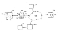
図18を参照する。実施例のいくつかにおいて、ポータブルデバイス100は、有機分子検知システム1802の部分であってよい。システム1802において、ポータブルデバイス100は、外部計算処理デバイス404に接続され、これにより、ポータブルデバイス100と計算処理デバイス404との間でデータを通信することができる。計算処理デバイス404は、スマートフォン、タブレットコンピュータ、ラップトップ、デスクトップ、埋め込み計算処理デバイス、ウェアラブルデバイス、または、サーバコンピュータなど、ポータブルデバイス100からデータを受信することができる任意のデバイスであってよい。ポータブルデバイス100は、任意の手段で計算処理デバイス404と通信し、これにより、ポータブルデバイス100と計算処理デバイス404との間のデータ伝送、有線接続(例えば、USBケーブル)または無線接続(例えば、ブルートゥース(登録商標)、WiFi)などによる、を可能とする。
See FIG. In some of the examples, the
実施例のいくつかにおいて、ポータブルデバイス100は、センサ112からセンサデータを計算処理デバイス404に送信する。これにより、計算処理デバイスプロセッサ408は、分析物がテスト混合物に存在するか否か評価するために、センサデータを解釈することを可能とする。計算処理デバイス404は、ディスプレイ412を含み、ユーザに結果を提示してもよいし、計算処理デバイス404はポータブルデバイスディスプレイ128で表示するためにポータブルデバイス100に結果を伝送し返してもよい。例えば、ポータブルデバイス100は、スマートフォン、タブレット、コンピュータ、または他の計算処理デバイスに、センサデータを伝送してもよい。計算処理デバイス上のソフトウェア動作は、データを解釈し、ディスプレイ上でユーザに結果を提供してもよい。ソフトウェアはアプリケーション、ウェブアプリケーションまたは他の実行可能なソフトウェアであってよい。代替的に、ポータブルデバイス100はポータブルデバイスプロセッサ124によって計算されるテスト結果(即ち、分析物がテスト混合物に存在するか否かの評価)を計算処理デバイス404に送信してもよい。
In some of the embodiments, the
ポータブルデバイス100または計算処理デバイス404で実行されるソフトウェア(例えば、スマートフォンアプリケーション、ウェブアプリケーション、埋め込みソフトウェア)は、テスト結果に関連するデータを収集してもよい。例えば、ポータブルデバイス100及び計算処理デバイス404の少なくとも一方は、テスト結果と位置情報とを関連付けてもよい。位置情報は、ポータブルデバイス100及び計算処理デバイス404の一方または両方と接続されている、または、内部に存在するGPSユニット416を使用して、判定されてもよいし、通信ネットワークプロトコル(例えば、携帯塔情報、ゲートウェイアドレス、またはIPアドレス)を使用して判定されてもよいし、ユーザ入力(例えば、データ入力ページまたはフォームの位置入力フィールドの、またはプロンプトに応じた)から受信されてもよい。
The software running on the
実施例のいくつかにおいて、ポータブルデバイス100または計算処理デバイス404は、コンテキスト情報とテスト結果とを関連付けてもよい。例えば、コンテキスト情報は、(レストランのメニューの食物製品の名称など)サンプル食物製品の名称、(ポータブルデバイス100及び計算処理デバイス404の一方または双方の内部、または、一方または双方に接続されているカメラ420で取得される、または、レストランウェブサイトまたはメニューからの画像など他のソースから取得される)食物製品の画像、及び、他の情報、ユーザ情報によって提供されるコメントまたはメモを含む食物情報を含んでいてもよい。
In some of the examples, the
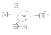
ポータブルデバイス100及び計算処理デバイス404の一方または双方は、ポータブルデバイス100及び計算処理デバイス404の一方または双方の内部の、または、一方または双方に接続されているストレージデバイス424に、テスト結果及び関連する情報(例えば、位置及び物質情報)を保存してもよい。実施例のいくつかにおいて、これにより、以前のテスト結果の位置(例えば、レストラン)を訪問する場合、以前のテスト結果の物質情報に対応する物質(例えば、食物)を使用する(例えば、食べる)場合など、後日、ユーザがこれらの結果を参照することを可能とする。これにより、以前のテスト結果に基づく判定をユーザに知らせることができる。実施例のいくつかにおいて、ポータブルデバイス100及び計算処理デバイス404の一方または双方が、インターネットなどのネットワーク428をわたる通信を行うことができる。図18は、ネットワーク428に接続された計算処理デバイス404による例を示す。図19は、ネットワーク428に接続されたポータブルデバイス100の例を示すシステム1902を例示する。ポータブルデバイス100及び計算処理デバイス404は、ネットワーク428に、及び/またはネットワーク428からのデータ伝送を可能とする任意の手段で、ネットワーク428に接続されていてもよい。例えば、ポータブルデバイス100及び計算処理デバイス404は、有線(例えば、USBケーブル)または無線(例えば、ブルートゥース、WiFi802.11、3G、またはLTE)により、ネットワーク428に接続されてもよい。
One or both of the
代替的に、または、ポータブルデバイス100または計算処理デバイス404のテスト結果(及び、必須ではない関連する位置及びコンテキスト情報)のローカルストレージに加えて、テスト結果及び/または関連する情報は、ネットワーク428をわたってサーバデバイス432と通信を行ってもよい。サーバデバイス432は、ポータブルデバイス100及び/または計算処理デバイス404、または他の匿名のデバイスに対応するユーザアカウントと接続されているストレージデバイス436に、テスト結果及び/または関連する情報を保存する。示されるように、サーバデバイス432は、複数の接続されているポータブルデバイス100及び/または計算処理デバイスから、テスト結果及び/または関連する情報を受信してもよいし、保存してもよい。これにより、テスト結果及び/または関連情報がサーバストレージデバイス436にまとめて保存されることを可能とする。実施例のいくつかにおいて、ポータブルデバイス100及び/または計算処理デバイス404は、サーバストレージデバイス436のデータに基づいて、情報を受信することができてもよい。例えば、ポータブルデバイス100及び/または計算処理デバイス404は、サーバデバイス436から、特定のメニューアイテムの特定の位置(例えば、レストラン)について、ポータブルデバイス100及び/または計算処理デバイス404のネットワークにより報告された物質(例えば、食物)のテスト結果を取得してもよい。ポータブルデバイス100は、ポータブルデバイスの位置に基づいて、自動的に、または、ユーザからのリクエストに応じて、取得されてもよい。これにより、報告されたテスト結果及び/またはユーザ及び他のユーザによって報告された関連情報に基づいて、使用(例えば、消費)される物質、及び、訪問される位置についての判定を、ユーザに知らせることができる。
Alternatively, or in addition to local storage of test results (and non-essential relevant location and context information) of
テスト結果及び/または関連情報は、サーバデバイス432のオペレータによって分析され、分析結果を準備するために、特定の原料を避けるなどの、食物準備ガイドラインでレストランまたは他の施設のコンプライアンスを評価してもよい。例えば、レストランのパフォーマンスに関して、レストランに報告を提供し、レストランで食物の安全性に関してポータブルデバイス100のユーザに報告を提供し、監督当局に報告を提供するために、分析結果が使用されてもよい。
The test results and / or relevant information may be analyzed by the operator of
テスト結果、関連情報及び/または分析結果は、位置についてのメニューと関連付けられていてもよいし、自動化された手段でユーザに提供されてもよい。例えば、ユーザは、計算処理デバイスのソフトウェア動作を使用して、レストランのメニューにアクセスしてもよい。メニューのアイテムは、以前記録されたテスト結果、関連情報及び/またはアイテムの分析結果に基づいて、注釈が付され、または識別されてもよい。 Test results, relevant information and / or analysis results may be associated with a menu of locations or may be provided to the user by automated means. For example, the user may use the software behavior of the computing device to access the restaurant menu. Menu items may be annotated or identified based on previously recorded test results, relevant information and / or item analysis results.
上記は実施例を提供するが、実施例で説明した特徴及び/または機能のいくつかは、上記実施例の動作原理及び思想から乖離せず変更可能である。したがって、上記は本発明の例示を意図し、限定を意図せず、他の変更が、本発明の範囲から乖離することなく、可能である。 Although the above provides examples, some of the features and / or functions described in the examples can be modified without departing from the operating principles and ideas of the above embodiments. Therefore, the above is intended to illustrate the invention, not to limit it, and other modifications are possible without departing from the scope of the invention.
(1)液体及び/または固体物質の対象有機分子と関連する分析物を検出するポータブルデバイスであって、
前記分析物と反応するよう選択された分析試薬を含む試液の液体を含み、突き刺し可能な膜壁でシールされている、テストチャンバと、
前記試液とテスト混合物を形成するように、前記テストチャンバにサンプルを配置するために、前記膜壁を突き刺すように、取り外し可能に配置されるプローブと、
前記分析物と前記分析試薬との間の反応を示す前記テストチャンバの前記テスト混合物の1つもしくは複数の特性を検出するように配置されたセンサと、
を含むポータブルデバイス。
(2)前記テスト混合物の前記特性の少なくとも1つを刺激する刺激源、
をさらに含む、
(1)のポータブルデバイス。
(3)前記刺激源は光源、電場源、電流源、及び磁場源の少なくとも1つを含む、
(2)のポータブルデバイス。
(4)前記1つもしくは複数の特性は、磁気、電気、及び光特性の1つもしくは複数を含む、
(1)のポータブルデバイス。
(5)前記センサと通信可能に接続され、検出された前記1つもしくは複数の特性に、少なくとも部分的に基づいて、前記分析物を前記サンプルが含むか否か評価するプロセッサ、
をさらに含む、
(1)のポータブルデバイス。
(6)前記分析物の存在を示すように制御可能なディスプレイ、
をさらに含む、
(1)のポータブルデバイス。
(7)前記センサに電気的に接続されたバッテリ、
をさらに含む、
(1)のポータブルデバイス。
(8)前記テストチャンバは照射窓及びセンサ窓をもち、
前記刺激源は、前記照射窓を通して、前記テストチャンバの少なくとも部分を照射するように向けられた光源を含み、
前記センサは、前記センサ窓を通して、前記テストチャンバから光放射を検出するように向けられた光センサを含む、
(2)のポータブルデバイス。
(9)前記テストチャンバは1μL〜250μLの前記試液を含む、
(1)のポータブルデバイス。
(10)前記テストチャンバは1mLより少ない容量をもつ、
(1)のポータブルデバイス。
(1) A portable device for detecting an analyte associated with a target organic molecule of a liquid and / or solid substance.
A test chamber and a test chamber containing a liquid of a test solution containing an analytical reagent selected to react with the analyte and sealed with a piercing membrane wall.
With a probe that is detachably placed to pierce the membrane wall to place the sample in the test chamber so as to form a test mixture with the test solution.
A sensor arranged to detect one or more properties of the test mixture in the test chamber indicating the reaction between the analyte and the analytical reagent.
Portable devices including.
(2) A stimulus source that stimulates at least one of the properties of the test mixture.
Including,
(1) Portable device.
(3) The stimulus source includes at least one of a light source, an electric field source, a current source, and a magnetic field source.
(2) Portable device.
(4) The one or more properties include one or more of magnetic, electrical, and optical properties.
(1) Portable device.
(5) A processor communicatively connected to the sensor and assessing whether the sample contains the analyte based on at least a partial basis on the detected characteristics of the one or more.
Including,
(1) Portable device.
(6) A display that can be controlled to indicate the presence of the analyte,
Including,
(1) Portable device.
(7) A battery electrically connected to the sensor,
Including,
(1) Portable device.
(8) The test chamber has an irradiation window and a sensor window, and has an irradiation window and a sensor window.
The stimulus source includes a light source directed to illuminate at least a portion of the test chamber through the irradiation window.
The sensor comprises an optical sensor directed to detect light emission from the test chamber through the sensor window.
(2) Portable device.
(9) The test chamber contains 1 μL to 250 μL of the test solution.
(1) Portable device.
(10) The test chamber has a capacity less than 1 mL.
(1) Portable device.
(11)前記光源は1つもしくは複数の第1波長をもつ光放射を射出し、
前記光センサは前記1つもしくは複数の第1波長とは異なる、1つもしくは複数の第2波長をもつ光放射を検出する、
(8)のポータブルデバイス。
(12)前記1つもしくは複数の第2波長は、前記1つもしくは複数の第1波長よりも長い、
(11)のポータブルデバイス。
(13)前記センサ、及び収容キャビティを含む本体、
をさらに含み、
前記テストチャンバは前記収容キャビティに配置可能で取り外し可能である、
(1)のポータブルデバイス。
(14)前記テストチャンバは廃棄可能で一回だけ使用される、
(13)のポータブルデバイス。
(15)前記収容キャビティに配置可能で取り外し可能な廃棄可能カートリッジ、
をさらに含み、
前記カートリッジは前記テストチャンバ及び入口通路を含み、
前記入口通路は前記プローブの少なくとも部分を受け入れるサイズを有し、
前記入口通路はダウンストリーム端とは反対側にアップストリーム端を有し、
前記ダウンストリーム端は膜を含む、
(13)のポータブルデバイス。
(16)少なくとも1つの第2テストチャンバ、
をさらに含み、
前記第2テストチャンバの各々は試液の液体の各々を含み、
前記第2テストチャンバの各々は突き刺し可能な膜壁の各々でシールされている、
(1)のポータブルデバイス。
(17)前記プローブは、前記膜壁を突き刺す尖ったプローブシャフト端をもつプローブシャフトを含む、
(1)のポータブルデバイス。
(18)前記プローブシャフトはリトラクタブルであり、
前記プローブシャフトは伸長位置及び収納位置をもつ、
(17)のポータブルデバイス。
(19)前記プローブは前記膜壁を突き刺す尖ったプローブシャフト端を含むプローブシャフトを含み、
前記プローブシャフトはリトラクタブルであり、
前記プローブシャフトは伸長位置及び収納位置をもち、
前記プローブが前記テストチャンバに伸長し、前記プローブシャフトが前記伸長位置である場合、前記プローブシャフトは、前記1つもしくは複数の特性を検出する前記センサと少なくとも部分的に干渉し、
前記センサによる検出の前記プローブシャフトによる干渉は、前記プローブが前記テストチャンバに伸長し、前記プローブシャフトが収納位置である場合、少なくとも部分的に低減される、
(8)のポータブルデバイス。
(20)前記プローブシャフト端は食物のサンプリングを容易にする形状及び面特徴の少なくとも一方を有する、
(17)のポータブルデバイス。
(11) The light source emits light radiation having one or a plurality of first wavelengths.
The optical sensor detects light emission having one or more second wavelengths different from the one or more first wavelengths.
(8) Portable device.
(12) The one or more second wavelengths are longer than the one or more first wavelengths.
(11) Portable device.
(13) The main body including the sensor and the accommodating cavity.
Including
The test chamber is removable and displaceable in the containment cavity.
(1) Portable device.
(14) The test chamber is disposable and used only once.
(13) Portable device.
(15) Disposable cartridges that can be placed and removed in the containment cavity,
Including
The cartridge includes the test chamber and an inlet passage.
The inlet passage is sized to accommodate at least a portion of the probe.
The entrance passage has an upstream end opposite to the downstream end.
The downstream edge contains a membrane,
(13) Portable device.
(16) At least one second test chamber,
Including
Each of the second test chambers contains each of the test solutions liquids.
Each of the second test chambers is sealed with each of the piercing membrane walls.
(1) Portable device.
(17) The probe includes a probe shaft having a pointed probe shaft end that pierces the membrane wall.
(1) Portable device.
(18) The probe shaft is retractable and is retractable.
The probe shaft has an extension position and a storage position.
(17) Portable device.
(19) The probe includes a probe shaft including a pointed probe shaft end that pierces the membrane wall.
The probe shaft is retractable and
The probe shaft has an extension position and a storage position, and has an extension position and a storage position.
When the probe extends into the test chamber and the probe shaft is in the extended position, the probe shaft interferes at least partially with the sensor that detects the one or more properties.
Interference by the probe shaft detected by the sensor is at least partially reduced when the probe extends into the test chamber and the probe shaft is in the retracted position.
(8) Portable device.
(20) The probe shaft end has at least one of shape and surface features that facilitates food sampling.
(17) Portable device.
(21)前記プローブはルーメン及び前記ルーメンのリトラクタブルプランジャーを含む、
(17)のポータブルデバイス。
(22)前記プローブシャフトは多孔性である、
(17)のポータブルデバイス。
(23)前記プローブシャフトはピットを有する、
(17)のポータブルデバイス。
(24)前記プローブシャフトは研磨性である、
(17)のポータブルデバイス。
(25)前記プローブシャフト端はキャビティを含む、
(17)のポータブルデバイス。
(26)液体及び/または固体物質の有機分子と関連する分析物を検出する方法であって、
テストチャンバに含まれる試薬を含む試液の液体にプローブからサンプルを配置するように、前記プローブでテストチャンバ壁を突き刺し、
前記サンプルと前記試液とを混合し、前記テストチャンバでテスト混合物を形成し、
前記分析物と前記分析試薬との間の反応を示す前記テストチャンバの前記テスト混合物の1つもしくは複数を検知する、
分析物を検出する方法。
(27)前記テストチャンバの前記テスト混合物の前記1つもしくは複数の特性を刺激する、
ことをさらに含む、
(26)の方法。
(28)前記テスト混合物の前記1つもしくは複数の特性を刺激することは、光放射及び磁場の少なくとも1つに、前記テストチャンバの前記テスト混合物を露出することを含む、
(27)の方法。
(29)前記検知の後、前記テストチャンバを廃棄する、
ことをさらに含む、
(26)の方法。
(30)前記突き刺す前に、
前記試液の前記1つもしくは複数の特性を検知する、
ことをさらに含む、
(26)の方法。
(31)前記突き刺す前に、
前記試液の前記1つもしくは複数の特性を刺激する、
ことをさらに含む、
(30)の方法。
(32)前記試液の検知された前記1つもしくは複数の特性と、前記テスト混合物の検知された前記1つもしくは複数の特性と、を比較し、前記サンプルに前記分析物が存在するか否か判定する、
ことをさらに含む、
(30)の方法。
(33)前記分析物が前記サンプルに存在すると判定された場合、前記分析物と関連する有機分子が前記サンプルに存在することを示す表示をディスプレイに表示する、
ことをさらに含む、
(32)の方法。
(34)前記分析物が前記サンプルに存在しないと判定された場合、前記分析物と関連する有機分子が前記サンプルに存在しないことを示す表示をディスプレイに表示する、
ことをさらに含む、
(32)の方法。
(35)前記プローブで物質を突き刺し、前記プローブで前記サンプルを収集する、
ことをさらに含む、
(26)の方法。
(36)前記試液と前記サンプルとを混合することは、前記試液を撹拌することを含む、
(26)の方法。
(37)前記試液を撹拌することは、前記テストチャンバを撹拌することを含む、
(36)の方法。
(38)前記試液を撹拌することは、前記テストチャンバの前記プローブの少なくともプローブシャフトを往復移動させることを含む、
(36)の方法。
(39)前記プローブで前記テストチャンバ壁を突き刺すことは、前記プローブのプローブシャフトが前記テスト混合物の前記1つもしくは複数の特性の検知と、少なくとも部分的に干渉する、ことを含み、
前記方法は、
前記プローブシャフトを収納することを含み、これにより、前記テスト混合物の前記1つもしくは複数の特性の検知で、前記プローブシャフトによる干渉を低減する、
(26)の方法。
(40)前記テストチャンバ壁を突き刺すことは、前記テストチャンバ壁が前記プローブからサンプルを取り除く、ことを含む、
(26)の方法。
(21) The probe includes a lumen and a retractable plunger of the lumen.
(17) Portable device.
(22) The probe shaft is porous.
(17) Portable device.
(23) The probe shaft has a pit.
(17) Portable device.
(24) The probe shaft is abrasive.
(17) Portable device.
(25) The probe shaft end includes a cavity.
(17) Portable device.
(26) A method for detecting an analyte associated with an organic molecule in a liquid and / or solid substance.
The probe pierces the test chamber wall so that the sample is placed from the probe into the liquid of the test solution containing the reagents contained in the test chamber.
The sample and the test solution are mixed to form a test mixture in the test chamber.
Detecting one or more of the test mixture in the test chamber showing a reaction between the analyte and the analytical reagent.
How to detect an analyte.
(27) Stimulate the one or more properties of the test mixture in the test chamber.
Including that
Method (26).
(28) Stimulating the one or more properties of the test mixture comprises exposing the test mixture in the test chamber to at least one of light radiation and a magnetic field.
Method (27).
(29) After the detection, the test chamber is discarded.
Including that
Method (26).
(30) Before the piercing
Detecting the one or more properties of the test solution,
Including that
Method (26).
(31) Before the piercing
Stimulates the one or more properties of the test solution.
Including that
Method (30).
(32) Whether or not the analyte is present in the sample by comparing the detected one or more properties of the test solution with the detected one or more properties of the test mixture. judge,
Including that
Method (30).
(33) When it is determined that the analysis product is present in the sample, a display indicating that the organic molecule associated with the analysis product is present in the sample is displayed on the display.
Including that
Method (32).
(34) When it is determined that the analysis product is not present in the sample, a display indicating that the organic molecule associated with the analysis product is not present in the sample is displayed on the display.
Including that
Method (32).
(35) The probe pierces the substance and the probe collects the sample.
Including that
Method (26).
(36) Mixing the test solution with the sample includes stirring the test solution.
Method (26).
(37) Stirring the test solution includes stirring the test chamber.
Method (36).
(38) Stirring the test solution involves reciprocating at least the probe shaft of the probe in the test chamber.
Method (36).
(39) Penetrating the test chamber wall with the probe comprises at least partially interfering with the detection of the one or more properties of the test mixture by the probe shaft of the probe.
The method is
Containing the probe shaft, thereby reducing interference by the probe shaft in detecting the one or more properties of the test mixture.
Method (26).
(40) Piercing the test chamber wall comprises removing the sample from the probe.
Method (26).
(41)刺激源とセンサとが位置合わせされた収容キャビティに前記テストチャンバを挿入する、
ことをさらに含む、
(26)の方法。
(42)液体及び/または固体物質に対象有機分子と関連する分析物を検出するポータブルデバイスと、
前記物質の1つもしくは複数のテストに関連するセンサデータを受信する前記ポータブルデバイスと結合される計算処理デバイスと、
を含み、
前記計算処理デバイスは、前記物質の前記分析物の存在に対応するテスト結果を生成するために、前記センサデータを分析するように動作する、
有機分子検知システム。
(43)テスト結果、位置情報及び/またはコンテキスト情報を受信するために、前記計算処理デバイスと通信するサーバデバイス、
をさらに含む、
(42)のシステム。
(44)液体及び/または固体の物質の対象有機分子と関連する分析物を検出し、前記物質の前記分析物の存在に対応するテスト結果を生成するように動作する、ポータブルデバイスと、
前記物質の前記分析物の存在に対応するテスト結果を受信するために、前記ポータブルデバイスと接続されている計算処理デバイスと、
を含む、
有機分子検知システム。
(45)テスト結果、位置情報及び/またはコンテキスト情報を受信するために、前記計算処理デバイスと通信するサーバデバイス、
をさらに含む、
(44)のシステム。
(41) Insert the test chamber into the containment cavity in which the stimulus source and the sensor are aligned.
Including that
Method (26).
(42) A portable device for detecting an analyte associated with a target organic molecule in a liquid and / or solid substance.
Computational processing devices coupled with said portable device that receive sensor data related to one or more tests of the substance.
Including
The computational processing device operates to analyze the sensor data in order to generate test results corresponding to the presence of the analyte of the substance.
Organic molecule detection system.
(43) A server device that communicates with the computational processing device to receive test results, location information and / or context information.
Including,
The system of (42).
(44) A portable device that operates to detect an analyte associated with a subject organic molecule of a liquid and / or solid substance and generate test results corresponding to the presence of the analyte of the substance.
A computational device connected to the portable device and a computational device to receive test results corresponding to the presence of the analyte of the substance.
including,
Organic molecule detection system.
(45) A server device that communicates with the computational processing device to receive test results, location information and / or context information.
Including,
The system of (44).
Claims (14)
前記分析物と反応するよう選択された分析試薬を含む試液の液体と、
突き刺し可能な膜壁(140)でシールされている、前記試液を含むテストチャンバ(108)と、
前記試液とテスト混合物を形成するように、前記テストチャンバにサンプルを配置するために、前記膜壁を突き刺すように、取り外し可能に配置されるプローブ(120)と、
磁気、電気、及び光特性の1つもしくは複数である、前記テスト混合物の特性の少なくとも1つを刺激する刺激源(112)と、
前記分析物と前記分析試薬との間の反応を示す前記テストチャンバの前記テスト混合物の前記少なくとも1つの特性の時間的なパターンを検出するように配置されたセンサ(116)と、
前記センサ(116)と通信可能に接続され、検出された前記少なくとも1つの特性の時間的なパターンに少なくとも部分的に基づいて、前記分析物を前記サンプルが含むか否か評価するように構成されているプロセッサ(124)と、
を含む、
ポータブルデバイス。 A portable device (100) for detecting an analyte associated with a target organic molecule of a liquid and / or solid substance.
The liquid of the test solution containing the analytical reagent selected to react with the analyte,
A test chamber (108) containing the test solution, sealed with a piercing membrane wall (140), and
A probe (120) detachably placed to pierce the membrane wall to place the sample in the test chamber to form a test mixture with the test solution.
A stimulus source (112) that stimulates at least one of the properties of the test mixture, which is one or more of the magnetic, electrical, and optical properties.
A sensor (116) arranged to detect the temporal pattern of at least one characteristic of the test mixture in the test chamber showing the reaction between the analyte and the analytical reagent.
It is communicably connected to the sensor (116) and is configured to assess whether the sample contains the analyte based on at least a partial temporal pattern of the detected at least one characteristic. Processor (124) and
including,
Portable device.
請求項1に記載のポータブルデバイス。 The stimulus source (112) includes at least one of a light source, an electric field source, a current source, and a magnetic field source.
The portable device according to claim 1.
請求項1または請求項2に記載のポータブルデバイス。 The temporal pattern comprises at least one first wavelength light emission followed by at least one second wavelength light emission.
The portable device according to claim 1 or 2.
を含む、
請求項1に記載のポータブルデバイス。 A display (128) that can be controlled to indicate the presence of said analyte,
including,
The portable device according to claim 1.
前記刺激源(112)は、前記照射窓を通して、前記テストチャンバの少なくとも部分を照射するように向けられた光源を含み、
前記センサ(116)は、前記センサ窓を通して、前記テストチャンバから光放射を検出するように向けられた光センサを含む、
請求項1に記載のポータブルデバイス。 The test chamber (108) has an irradiation window (164) and a sensor window (168).
The stimulus source (112) includes a light source directed to illuminate at least a portion of the test chamber through the irradiation window.
The sensor (116) includes an optical sensor directed to detect light emission from the test chamber through the sensor window.
The portable device according to claim 1.
前記テストチャンバは1mLより少ない容量をもつ、
請求項1〜請求項5の何れか1項に記載のポータブルデバイス。 The test chamber contains 1 μL to 250 μL of the test solution or contains
The test chamber has a capacity of less than 1 mL.
The portable device according to any one of claims 1 to 5.
を含み、
前記テストチャンバ(108)は前記収容キャビティに配置可能で取り外し可能である、
請求項1〜請求項6の何れか1項に記載のポータブルデバイス。 The body (104), which includes the sensor (116) and the containment cavity (144).
Including
The test chamber (108) is removable and displaceable in the containment cavity.
The portable device according to any one of claims 1 to 6.
前記ポータブルデバイスは、
前記収容キャビティ(144)に配置可能で取り外し可能な廃棄可能なカートリッジ(132)、
をさらに含み、
前記カートリッジは前記テストチャンバ及び入口通路(176)を含み、
前記入口通路は前記プローブ(120)の少なくとも部分を受け入れるサイズを有し、
前記入口通路はダウンストリーム端とは反対側にアップストリーム端を有し、
前記ダウンストリーム端は膜(140)を含む、
請求項7に記載のポータブルデバイス。 The test chamber (108) is disposable and can be used only once or
The portable device is
Disposable cartridge (132), removable and removable in said containment cavity (144),
Including
The cartridge includes the test chamber and an inlet passage (176).
The inlet passage is sized to accommodate at least a portion of the probe (120).
The entrance passage has an upstream end opposite to the downstream end.
The downstream end comprises a membrane (140).
The portable device according to claim 7.
をさらに含み、
前記第2テストチャンバの各々は試液の液体の各々を含み、
前記第2テストチャンバの各々は突き刺し可能な膜壁の各々でシールされている、
請求項1〜請求項8の何れか1項に記載のポータブルデバイス。 At least one second test chamber (108),
Including
Each of the second test chambers contains each of the test solutions liquids.
Each of the second test chambers is sealed with each of the piercing membrane walls.
The portable device according to any one of claims 1 to 8.
前記プローブシャフトはリトラクタブルであり、
前記プローブシャフトは伸長位置及び収納位置をもち、
前記プローブが前記テストチャンバに伸長し、前記プローブシャフトが前記伸長位置で
ある場合、前記プローブシャフトは、前記1つもしくは複数の特性を検出する前記センサと少なくとも部分的に干渉し、
前記センサによる検出の前記プローブシャフトによる干渉は、前記プローブが前記テストチャンバに伸長し、前記プローブシャフトが収納位置である場合、少なくとも部分的に低減される、
請求項1〜請求項9の何れか1項に記載のポータブルデバイス。 The probe (120) includes a probe shaft (192) having a pointed probe shaft end that pierces the membrane wall (140).
The probe shaft is retractable and
The probe shaft has an extension position and a storage position, and has an extension position and a storage position.
When the probe extends into the test chamber and the probe shaft is in the extended position, the probe shaft interferes at least partially with the sensor that detects the one or more properties.
Interference by the probe shaft detected by the sensor is at least partially reduced when the probe extends into the test chamber and the probe shaft is in the retracted position.
The portable device according to any one of claims 1 to 9.
テストチャンバ(108)に含まれる前記分析物と反応するように選択された試薬を含む試液の液体にプローブ(120)からサンプルを配置するように、前記プローブ(120)でテストチャンバ壁(140)を突き刺し、
前記サンプルと前記試液とを混合し、前記テストチャンバでテスト混合物を形成し、
磁気、電気、及び光特性の1つもしくは複数である、前記テストチャンバの前記テスト混合物の少なくとも1つの特性を刺激し、
前記分析物と分析試薬との間の反応を示す前記テストチャンバの前記テスト混合物の1つもしくは複数の特性の時間的なパターンを検知し、
少なくとも1つの検出された前記特性の、検知された前記時間的なパターンに、少なくとも部分的に基づいて、前記サンプルが前記分析物を含むか否か評価する、
分析物を検出する方法。 A method of detecting an analyte associated with an organic molecule in a liquid and / or solid substance.
The test chamber wall (140) with the probe (120) so that the sample is placed from the probe (120) in the liquid of the test solution containing the reagent selected to react with the analyte contained in the test chamber (108). Stab and
The sample and the test solution are mixed to form a test mixture in the test chamber.
Stimulate at least one property of the test mixture in the test chamber, which is one or more of the magnetic, electrical, and light properties.
The temporal pattern of one or more properties of the test mixture in the test chamber indicating the reaction between the analyte and the analytical reagent is detected.
Evaluate whether the sample contains the analyte, at least in part, based on the detected temporal pattern of at least one of the detected properties.
How to detect an analyte.
前記試液の前記1つもしくは複数の特性を検知する、
ことをさらに含む、
請求項11に記載の方法。 Before the piercing
Detecting the one or more properties of the test solution,
Including that
11. The method of claim 11.
ことをさらに含む、
請求項12に記載の方法。 The detected one or more properties of the test solution are compared with the detected one or more properties of the test mixture to determine if the analyte is present in the sample.
Including that
The method according to claim 12.
請求項11に記載の方法。 The temporal pattern comprises at least one first wavelength light emission followed by at least one second wavelength light emission.
11. The method of claim 11.
Applications Claiming Priority (3)
| Application Number | Priority Date | Filing Date | Title |
|---|---|---|---|
| US201562153922P | 2015-04-28 | 2015-04-28 | |
| US62/153,922 | 2015-04-28 | ||
| PCT/CA2016/050492 WO2016172800A1 (en) | 2015-04-28 | 2016-04-28 | Portable organic molecular sensing device and related systems and methods |
Publications (3)
| Publication Number | Publication Date |
|---|---|
| JP2018524605A JP2018524605A (en) | 2018-08-30 |
| JP2018524605A5 JP2018524605A5 (en) | 2019-06-06 |
| JP6927546B2 true JP6927546B2 (en) | 2021-09-01 |
Family
ID=57197977
Family Applications (1)
| Application Number | Title | Priority Date | Filing Date |
|---|---|---|---|
| JP2018507757A Active JP6927546B2 (en) | 2015-04-28 | 2016-04-28 | Portable Organic Molecule Detection Devices and Related Systems and Methods |
Country Status (6)
| Country | Link |
|---|---|
| US (2) | US10605740B2 (en) |
| EP (1) | EP3289331B1 (en) |
| JP (1) | JP6927546B2 (en) |
| CN (1) | CN107735664A (en) |
| CA (1) | CA2983806C (en) |
| WO (1) | WO2016172800A1 (en) |
Families Citing this family (15)
| Publication number | Priority date | Publication date | Assignee | Title |
|---|---|---|---|---|
| WO2016172800A1 (en) | 2015-04-28 | 2016-11-03 | Aterica Inc. | Portable organic molecular sensing device and related systems and methods |
| CN109313331A (en) * | 2016-06-20 | 2019-02-05 | Ran 生物技术公司 | Reader device |
| DE102017005835B4 (en) * | 2017-06-20 | 2020-04-02 | Diehl Metering Gmbh | Device for the mobile determination of a property of a liquid, solid or gaseous sample |
| US10267790B1 (en) | 2017-11-17 | 2019-04-23 | Ultima Genomics, Inc. | Systems for biological sample processing and analysis |
| US11499962B2 (en) | 2017-11-17 | 2022-11-15 | Ultima Genomics, Inc. | Methods and systems for analyte detection and analysis |
| US11280805B2 (en) * | 2018-06-05 | 2022-03-22 | Chemthief, Llc | Robot device for collection of solid, liquid and/or multiphase samples |
| EP3833242B1 (en) | 2018-08-07 | 2024-01-03 | BriteScan, LLC | Portable scanning device for ascertaining attributes of sample materials |
| US11054370B2 (en) * | 2018-08-07 | 2021-07-06 | Britescan, Llc | Scanning devices for ascertaining attributes of tangible objects |
| EP3660160A1 (en) * | 2018-11-28 | 2020-06-03 | GTZ Microlab Detect, S.L. | Portable device and method for detecting microorganisms or metabolites in a sample |
| US10512911B1 (en) * | 2018-12-07 | 2019-12-24 | Ultima Genomics, Inc. | Implementing barriers for controlled environments during sample processing and detection |
| US11118223B2 (en) | 2019-03-14 | 2021-09-14 | Ultima Genomics, Inc. | Methods, devices, and systems for analyte detection and analysis |
| KR102575316B1 (en) * | 2021-02-04 | 2023-09-06 | 울산과학기술원 | Sample chamber for selective plane illumination microscopy |
| CN113176254B (en) * | 2021-04-23 | 2022-09-16 | 津制仪表(天津)有限公司 | Environmental climate multi-parameter online detector |
| CN113786873B (en) * | 2021-08-31 | 2022-09-23 | 广西横县张一元饮品有限公司 | Test tube for food safety detection |
| CN116500290B (en) * | 2023-06-21 | 2023-09-08 | 长沙海纳光电科技有限公司 | Supersaturated solid medicament adding device and method based on transmission method |
Family Cites Families (20)
| Publication number | Priority date | Publication date | Assignee | Title |
|---|---|---|---|---|
| DE2422260B2 (en) * | 1974-05-08 | 1979-04-12 | Compur-Electronic Gmbh, 8000 Muenchen | Device for the production of a measuring liquid to be optically examined |
| CH585403A5 (en) * | 1974-05-10 | 1977-02-28 | Battelle Memorial Institute | |
| JPS54108693A (en) | 1978-02-14 | 1979-08-25 | Mitsubishi Chem Ind | Method and device for optically measuring antigennantibody reaction |
| DK0610325T3 (en) * | 1991-11-01 | 1997-10-27 | Univ Birmingham | An assay device |
| WO1997003209A1 (en) * | 1995-07-12 | 1997-01-30 | Charm Sciences, Inc. | Test apparatus, system and method for the detection of test samples |
| DE69627770T2 (en) * | 1995-09-05 | 2004-02-26 | Biotrace Ltd. | Procedure for determining the total amount of chlorine and kit therefor |
| US5917592A (en) * | 1997-02-28 | 1999-06-29 | Charm Sciences, Inc. | Photometer, and test sample holder for use therein, method and system |
| GB2350421B (en) * | 1999-05-18 | 2003-12-17 | Krysium Advisors Ltd | Apparatus and method of testing a biological fluid |
| US7122153B2 (en) * | 2003-01-08 | 2006-10-17 | Ho Winston Z | Self-contained microfluidic biochip and apparatus |
| US20050221281A1 (en) * | 2003-01-08 | 2005-10-06 | Ho Winston Z | Self-contained microfluidic biochip and apparatus |
| JP4557014B2 (en) * | 2008-02-14 | 2010-10-06 | ソニー株式会社 | Fluorescently labeled oligonucleotide for nucleic acid detection, and method for obtaining information related to duplex formation using the fluorescently labeled oligonucleotide for nucleic acid detection |
| CN102016540A (en) * | 2008-04-11 | 2011-04-13 | 梅索斯卡莱科技公司 | Assay apparatuses, methods and reagents |
| EP2302029A1 (en) * | 2009-09-29 | 2011-03-30 | Fundacion Gaiker | Portable enrichment, aliquoting, and testing device of microorganisms and toxins |
| WO2012078455A1 (en) * | 2010-12-06 | 2012-06-14 | Exploramed Iii, Inc. | Allergen test kit |
| JP5922678B2 (en) * | 2011-01-08 | 2016-05-24 | アクセス メディカル システムズ,リミティド | System for immunoassay testing |
| IN2014DN08556A (en) * | 2012-03-27 | 2015-05-22 | Univ Northwestern | |
| US9446406B2 (en) * | 2012-06-29 | 2016-09-20 | Biocontrol Systems, Inc. | Sample collection and bioluminescent analysis system |
| EP2979092B1 (en) * | 2013-03-29 | 2018-05-30 | Nima Labs, Inc. | A portable device for detection of harmful substances |
| DE102014001284B3 (en) * | 2014-02-01 | 2015-01-22 | aquila biolabs GmbH | Method, apparatus and system for the automated determination of optical densities or the variation of optical densities of reaction mixtures in shaken reactors |
| WO2016172800A1 (en) | 2015-04-28 | 2016-11-03 | Aterica Inc. | Portable organic molecular sensing device and related systems and methods |
-
2016
- 2016-04-28 WO PCT/CA2016/050492 patent/WO2016172800A1/en active Application Filing
- 2016-04-28 CA CA2983806A patent/CA2983806C/en active Active
- 2016-04-28 JP JP2018507757A patent/JP6927546B2/en active Active
- 2016-04-28 EP EP16785714.3A patent/EP3289331B1/en active Active
- 2016-04-28 CN CN201680037465.1A patent/CN107735664A/en active Pending
-
2017
- 2017-10-26 US US15/794,070 patent/US10605740B2/en active Active
-
2020
- 2020-02-27 US US16/802,785 patent/US11408826B2/en active Active
Also Published As
| Publication number | Publication date |
|---|---|
| US20200271589A1 (en) | 2020-08-27 |
| EP3289331A4 (en) | 2018-10-31 |
| US20180073986A1 (en) | 2018-03-15 |
| CA2983806A1 (en) | 2016-11-03 |
| CN107735664A (en) | 2018-02-23 |
| US10605740B2 (en) | 2020-03-31 |
| WO2016172800A1 (en) | 2016-11-03 |
| JP2018524605A (en) | 2018-08-30 |
| US11408826B2 (en) | 2022-08-09 |
| CA2983806C (en) | 2023-06-13 |
| EP3289331A1 (en) | 2018-03-07 |
| EP3289331B1 (en) | 2020-12-30 |
Similar Documents
| Publication | Publication Date | Title |
|---|---|---|
| JP6927546B2 (en) | Portable Organic Molecule Detection Devices and Related Systems and Methods | |
| US10031076B2 (en) | Mobile smart device infrared light measuring apparatus, method, and system for analyzing substances | |
| US11231404B1 (en) | Sampling and detection kit for chemical and biological materials | |
| US11385146B2 (en) | Sampling systems and techniques to collect hazardous contaminants with high pickup and shedding efficiencies | |
| US20130273666A1 (en) | Color-Based Reaction Testing of Biological Materials | |
| US10375909B2 (en) | Diagnostics systems and methods | |
| JP2018524605A5 (en) | ||
| US20220018827A1 (en) | Solution collection device with evaluation element | |
| JP2014526695A (en) | Diagnostic equipment | |
| CN109922732B (en) | Diagnostic system and method | |
| KR20220134626A (en) | Seat ring comprising a device for obtaining a value | |
| JP2017508586A (en) | Sample testing device with lancet advance tracking and color touch screen user interface | |
| US11740181B2 (en) | Preparation device, diagnostic apparatus, diagnostic kit and diagnostic system | |
| JP5554345B2 (en) | Measuring device for body fluid analysis | |
| CN214066932U (en) | Device for rapidly displaying coronavirus test results | |
| JP7493500B2 (en) | Portable Dielectric Spectroscopy Instrument |
Legal Events
| Date | Code | Title | Description |
|---|---|---|---|
| A521 | Request for written amendment filed |
Free format text: JAPANESE INTERMEDIATE CODE: A523 Effective date: 20190426 |
|
| A621 | Written request for application examination |
Free format text: JAPANESE INTERMEDIATE CODE: A621 Effective date: 20190426 |
|
| A977 | Report on retrieval |
Free format text: JAPANESE INTERMEDIATE CODE: A971007 Effective date: 20200226 |
|
| A131 | Notification of reasons for refusal |
Free format text: JAPANESE INTERMEDIATE CODE: A131 Effective date: 20200317 |
|
| A601 | Written request for extension of time |
Free format text: JAPANESE INTERMEDIATE CODE: A601 Effective date: 20200617 |
|
| A521 | Request for written amendment filed |
Free format text: JAPANESE INTERMEDIATE CODE: A523 Effective date: 20200910 |
|
| A131 | Notification of reasons for refusal |
Free format text: JAPANESE INTERMEDIATE CODE: A131 Effective date: 20210112 |
|
| A521 | Request for written amendment filed |
Free format text: JAPANESE INTERMEDIATE CODE: A523 Effective date: 20210326 |
|
| TRDD | Decision of grant or rejection written | ||
| A01 | Written decision to grant a patent or to grant a registration (utility model) |
Free format text: JAPANESE INTERMEDIATE CODE: A01 Effective date: 20210706 |
|
| A61 | First payment of annual fees (during grant procedure) |
Free format text: JAPANESE INTERMEDIATE CODE: A61 Effective date: 20210728 |
|
| R150 | Certificate of patent or registration of utility model |
Ref document number: 6927546 Country of ref document: JP Free format text: JAPANESE INTERMEDIATE CODE: R150 |
|
| R250 | Receipt of annual fees |
Free format text: JAPANESE INTERMEDIATE CODE: R250 |