JP6926085B2 - Secure Things Internet of Things (IoT) Device Provisioning Systems and Methods - Google Patents
Secure Things Internet of Things (IoT) Device Provisioning Systems and Methods Download PDFInfo
- Publication number
- JP6926085B2 JP6926085B2 JP2018531069A JP2018531069A JP6926085B2 JP 6926085 B2 JP6926085 B2 JP 6926085B2 JP 2018531069 A JP2018531069 A JP 2018531069A JP 2018531069 A JP2018531069 A JP 2018531069A JP 6926085 B2 JP6926085 B2 JP 6926085B2
- Authority
- JP
- Japan
- Prior art keywords
- iot
- service
- iot device
- hub
- code
- Prior art date
- Legal status (The legal status is an assumption and is not a legal conclusion. Google has not performed a legal analysis and makes no representation as to the accuracy of the status listed.)
- Active
Links
Images


Classifications
-
- G—PHYSICS
- G06—COMPUTING; CALCULATING OR COUNTING
- G06F—ELECTRIC DIGITAL DATA PROCESSING
- G06F21/00—Security arrangements for protecting computers, components thereof, programs or data against unauthorised activity
- G06F21/70—Protecting specific internal or peripheral components, in which the protection of a component leads to protection of the entire computer
- G06F21/71—Protecting specific internal or peripheral components, in which the protection of a component leads to protection of the entire computer to assure secure computing or processing of information
- G06F21/73—Protecting specific internal or peripheral components, in which the protection of a component leads to protection of the entire computer to assure secure computing or processing of information by creating or determining hardware identification, e.g. serial numbers
-
- G—PHYSICS
- G06—COMPUTING; CALCULATING OR COUNTING
- G06F—ELECTRIC DIGITAL DATA PROCESSING
- G06F21/00—Security arrangements for protecting computers, components thereof, programs or data against unauthorised activity
- G06F21/30—Authentication, i.e. establishing the identity or authorisation of security principals
- G06F21/31—User authentication
- G06F21/42—User authentication using separate channels for security data
-
- G—PHYSICS
- G06—COMPUTING; CALCULATING OR COUNTING
- G06F—ELECTRIC DIGITAL DATA PROCESSING
- G06F21/00—Security arrangements for protecting computers, components thereof, programs or data against unauthorised activity
- G06F21/30—Authentication, i.e. establishing the identity or authorisation of security principals
- G06F21/44—Program or device authentication
-
- H—ELECTRICITY
- H04—ELECTRIC COMMUNICATION TECHNIQUE
- H04L—TRANSMISSION OF DIGITAL INFORMATION, e.g. TELEGRAPHIC COMMUNICATION
- H04L9/00—Cryptographic mechanisms or cryptographic arrangements for secret or secure communications; Network security protocols
- H04L9/006—Cryptographic mechanisms or cryptographic arrangements for secret or secure communications; Network security protocols involving public key infrastructure [PKI] trust models
-
- H—ELECTRICITY
- H04—ELECTRIC COMMUNICATION TECHNIQUE
- H04L—TRANSMISSION OF DIGITAL INFORMATION, e.g. TELEGRAPHIC COMMUNICATION
- H04L9/00—Cryptographic mechanisms or cryptographic arrangements for secret or secure communications; Network security protocols
- H04L9/08—Key distribution or management, e.g. generation, sharing or updating, of cryptographic keys or passwords
- H04L9/0816—Key establishment, i.e. cryptographic processes or cryptographic protocols whereby a shared secret becomes available to two or more parties, for subsequent use
- H04L9/0838—Key agreement, i.e. key establishment technique in which a shared key is derived by parties as a function of information contributed by, or associated with, each of these
- H04L9/0841—Key agreement, i.e. key establishment technique in which a shared key is derived by parties as a function of information contributed by, or associated with, each of these involving Diffie-Hellman or related key agreement protocols
-
- H—ELECTRICITY
- H04—ELECTRIC COMMUNICATION TECHNIQUE
- H04L—TRANSMISSION OF DIGITAL INFORMATION, e.g. TELEGRAPHIC COMMUNICATION
- H04L9/00—Cryptographic mechanisms or cryptographic arrangements for secret or secure communications; Network security protocols
- H04L9/14—Cryptographic mechanisms or cryptographic arrangements for secret or secure communications; Network security protocols using a plurality of keys or algorithms
-
- H—ELECTRICITY
- H04—ELECTRIC COMMUNICATION TECHNIQUE
- H04L—TRANSMISSION OF DIGITAL INFORMATION, e.g. TELEGRAPHIC COMMUNICATION
- H04L9/00—Cryptographic mechanisms or cryptographic arrangements for secret or secure communications; Network security protocols
- H04L9/32—Cryptographic mechanisms or cryptographic arrangements for secret or secure communications; Network security protocols including means for verifying the identity or authority of a user of the system or for message authentication, e.g. authorization, entity authentication, data integrity or data verification, non-repudiation, key authentication or verification of credentials
- H04L9/3226—Cryptographic mechanisms or cryptographic arrangements for secret or secure communications; Network security protocols including means for verifying the identity or authority of a user of the system or for message authentication, e.g. authorization, entity authentication, data integrity or data verification, non-repudiation, key authentication or verification of credentials using a predetermined code, e.g. password, passphrase or PIN
-
- G—PHYSICS
- G06—COMPUTING; CALCULATING OR COUNTING
- G06F—ELECTRIC DIGITAL DATA PROCESSING
- G06F2221/00—Indexing scheme relating to security arrangements for protecting computers, components thereof, programs or data against unauthorised activity
- G06F2221/21—Indexing scheme relating to G06F21/00 and subgroups addressing additional information or applications relating to security arrangements for protecting computers, components thereof, programs or data against unauthorised activity
- G06F2221/2117—User registration
-
- H—ELECTRICITY
- H04—ELECTRIC COMMUNICATION TECHNIQUE
- H04L—TRANSMISSION OF DIGITAL INFORMATION, e.g. TELEGRAPHIC COMMUNICATION
- H04L2209/00—Additional information or applications relating to cryptographic mechanisms or cryptographic arrangements for secret or secure communication H04L9/00
- H04L2209/80—Wireless
- H04L2209/805—Lightweight hardware, e.g. radio-frequency identification [RFID] or sensor
-
- H—ELECTRICITY
- H04—ELECTRIC COMMUNICATION TECHNIQUE
- H04W—WIRELESS COMMUNICATION NETWORKS
- H04W88/00—Devices specially adapted for wireless communication networks, e.g. terminals, base stations or access point devices
- H04W88/08—Access point devices
- H04W88/10—Access point devices adapted for operation in multiple networks, e.g. multi-mode access points
Description
本発明は、概して、コンピュータシステムの分野に関する。より具体的には、本発明は、安全なモノのインターネット(IoT)デバイスプロビジョニングのためのシステム及び方法に関する。 The present invention generally relates to the field of computer systems. More specifically, the present invention relates to systems and methods for secure Internet of Things (IoT) device provisioning.
[関連技術の説明]
「モノのインターネット」は、インターネットインフラストラクチャ内に、一意的に識別可能に組み込まれたデバイスの相互接続を指す。最終的に、IoTは、事実上あらゆるタイプの物理的なモノが、それ自体若しくはその周囲についての情報を提供し得、及び/又はインターネットをわたってクライアントデバイスを介して遠隔制御され得る、広範囲の新しいタイプのアプリケーションをもたらすことが期待される。
[Explanation of related technologies]
The "Internet of Things" refers to the interconnection of devices that are uniquely and identifiablely embedded within the Internet infrastructure. Ultimately, the IoT is a wide range of physical objects of virtually any type that can provide information about themselves or their surroundings and / or be remotely controlled via client devices across the Internet. Expected to bring new types of applications.
接続性、電力、及び規格化の欠如に関連する問題のために、IoT開発及び採用は遅れている。例えば、IoT開発及び採用に対する1つの障害は、開発者が新しいIoTデバイス及びサービスを設計して提供することを可能にする標準プラットフォームが存在しないことである。IoT市場に参入するためには、開発者は、所望のIoT実装に対応するために必要なネットワークプロトコル及びインフラストラクチャ、ハードウェア、ソフトウェア、並びにサービスを含む、IoTプラットフォーム全体を一から設計する必要がある。その結果、IoTデバイスの各プロバイダは、IoTデバイスの設計と接続のために専有の技術を使用しており、エンドユーザにとって複数のタイプのIoTデバイスの採用が厄介となっている。IoTの採用への別の障害は、IoTデバイスの接続及び給電に関連する困難である。例えば、冷蔵庫、ガレージドアオープナー、環境センサ、家庭用セキュリティセンサ/コントローラなどの接続機器は、接続された各IoT機器に給電するための電源を必要とし、そのような電源はしばしば便利な位置に設けられていない。 IoT development and adoption has been delayed due to issues related to connectivity, power, and lack of standardization. For example, one obstacle to IoT development and adoption is the lack of a standard platform that allows developers to design and deliver new IoT devices and services. To enter the IoT market, developers need to design the entire IoT platform from scratch, including the network protocols and infrastructure, hardware, software, and services needed to support the desired IoT implementation. be. As a result, each IoT device provider uses proprietary technology to design and connect IoT devices, making it difficult for end users to adopt multiple types of IoT devices. Another obstacle to the adoption of IoT is the difficulty associated with connecting and powering IoT devices. For example, connected devices such as refrigerators, garage door openers, environment sensors, and home security sensors / controllers require a power source to power each connected IoT device, and such power sources are often located in convenient locations. Not done.
存在する別の問題は、Bluetooth(登録商標) LE(BTLE)などのIoTデバイスを相互接続するために使用される無線技術が、概して、近距離技術であるということである。したがって、IoT実装のためのデータ収集ハブがIoTデバイスの範囲外にある場合、そのIoTデバイスは、IoTハブにデータを送信することができない(逆もまた同様)。その結果として、IoTデバイスが、範囲外にあるIoTハブ(又は他のIoTデバイス)にデータを提供することを可能にする技術が必要とされる。 Another problem that exists is that the wireless technology used to interconnect IoT devices, such as Bluetooth® LE (BTLE), is generally a short range technology. Therefore, if the data collection hub for IoT implementation is outside the scope of the IoT device, the IoT device will not be able to send data to the IoT hub (and vice versa). As a result, there is a need for technology that allows IoT devices to provide data to IoT hubs (or other IoT devices) that are out of range.
加えて、BTLEなどの無線通信プロトコルに依存する現在のIoT実装は、適切なセキュリティ対策を提供しない。したがって、追加の技術が、IoT実装においてセキュリティを向上させるために必要とされる。 In addition, current IoT implementations that rely on wireless communication protocols such as BTLE do not provide adequate security measures. Therefore, additional techniques are needed to improve security in IoT implementations.
本発明のより良好な理解は、以下の図面と併せた以下の詳細な説明から得ることができる。 A better understanding of the present invention can be obtained from the following detailed description in conjunction with the following drawings.
以下の説明では、説明を目的として、以下に記載される本発明の実施形態の完全な理解を提供するために、多数の特定の詳細が示される。しかしながら、本発明の実施形態がこれらの特定の詳細のうちのいくつかを用いずに実施され得ることは、当業者には明らかである。他の例では、本発明の実施形態の根本的な原理を不明瞭にすることを避けるために、周知の構造及びデバイスをブロック図の形態で示す。 In the following description, for purposes of illustration, a number of specific details are provided to provide a complete understanding of the embodiments of the invention described below. However, it will be apparent to those skilled in the art that embodiments of the present invention may be practiced without some of these particular details. In other examples, well-known structures and devices are shown in block diagram form to avoid obscuring the underlying principles of embodiments of the present invention.
本発明の一実施形態は、新しいIoTデバイス及びアプリケーションを設計及び構築するために開発者によって利用され得るモノのインターネット(IoT)プラットフォームを含む。具体的には、一実施形態は、既定のネットワーキングプロトコルスタックを含むIoTデバイス、及びIoTデバイスがインターネットに連結されるIoTハブ用の基本ハードウェア/ソフトウェアプラットフォームを含む。加えて、一実施形態は、IoTサービスを含み、これを通じてIoTハブ及び接続されたIoTデバイスが、以下に説明するようにアクセスされ、管理され得る。加えて、IoTプラットフォームの一実施形態は、IoTサービス、ハブ、及び接続されたデバイスにアクセスし、それらを構成する、IoTアプリケーション又はウェブアプリケーション(例えば、クライアントデバイス上で実行される)を含む。既存のオンライン小売業者及び他のウェブサイトオペレータは、本明細書に記載されたIoTプラットフォームを利用して、既存のユーザベースに独自のIoT機能を容易に提供することができる。 One embodiment of the invention includes an Internet of Things (IoT) platform that can be used by developers to design and build new IoT devices and applications. Specifically, one embodiment includes an IoT device that includes a default networking protocol stack, and a basic hardware / software platform for an IoT hub to which the IoT device is connected to the Internet. In addition, one embodiment includes an IoT service through which the IoT hub and connected IoT devices can be accessed and managed as described below. In addition, one embodiment of the IoT platform includes IoT services, hubs, and IoT applications or web applications (eg, running on client devices) that access and configure IoT services, hubs, and connected devices. Existing online retailers and other website operators can easily leverage the IoT platforms described herein to provide their own IoT capabilities to their existing user base.
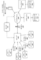
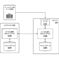
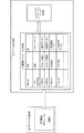
図1Aは、本発明の実施形態を実装することができるアーキテクチャプラットフォームの概要を例示する。具体的には、図示の実施形態は、それ自体インターネット220を介してIoTサービス120に通信可能に連結されている中央IoTハブ110に、ローカル通信チャネル130を介して通信可能に連結された複数のIoTデバイス101〜105を含む。IoTデバイス101〜105のそれぞれは、ローカル通信チャネル130のそれぞれを有効にするために、IoTハブ110と最初にペアリングすることができる(例えば、後述するペアリング技術を使用して)。一実施形態では、IoTサービス120は、各ユーザのIoTデバイスから収集されたユーザアカウント情報及びデータを維持するためのエンドユーザデータベース122を含む。例えば、IoTデバイスがセンサ(例えば、温度センサ、加速度計、熱センサ、動作検出器など)を含む場合、データベース122は、IoTデバイス101〜105により収集されるデータを記憶するように継続的に更新され得る。次いで、データベース122内に記憶されたデータは、ユーザデバイス135上にインストールされたIoTアプリケーション又はブラウザを介して(又はデスクトップ若しくは他のクライアントコンピュータシステムを介して)エンドユーザに、かつウェブクライアント(例えば、IoTサービス120に加入しているウェブサイト130など)に、アクセス可能にされてもよい。
FIG. 1A illustrates an overview of an architectural platform on which embodiments of the present invention can be implemented. Specifically, the illustrated embodiment is a plurality of communicably linked
IoTデバイス101〜105には、それ自体及びその周辺に関する情報を収集し、収集された情報を、IoTハブ110を介してIoTサービス120、ユーザデバイス135、及び/又は外部ウェブサイト130に提供するための様々なタイプのセンサが備わっていてもよい。IoTデバイス101〜105のうちのいくつかは、IoTハブ110を介して送信される制御コマンドに応答して、指定された機能を実行することができる。IoTデバイス101〜105によって収集される情報の様々な具体例及び制御コマンドが以下に提供される。以下に説明する一実施形態では、IoTデバイス101は、ユーザ選択を記録し、ユーザ選択をIoTサービス120及び/又はウェブサイトに送信するように設計されたユーザ入力デバイスである。
The IoT devices 101-105 collect information about itself and its surroundings and provide the collected information to the
一実施形態では、IoTハブ110は、4G(例えば、モバイルWiMAX、LTE)又は5Gセルラーデータサービスなどのセルラーサービス115を介してインターネット220への接続を確立するセルラー無線を含む。代替的に、又は加えて、IoTハブ110は、WiFiアクセスポイント又はルータ116を介してWiFi接続を確立するためのWiFi無線を含むことができ、これは、IoTハブ110をインターネットに(例えば、エンドユーザにインターネットサービスを提供するインターネットサービスプロバイダを介して)連結する。当然のことながら、本発明の基本的な原理は、特定のタイプの通信チャネル又はプロトコルに限定されないことに留意すべきである。
In one embodiment, the
一実施形態では、IoTデバイス101〜105は、電池電力で長期間(例えば、数年)動作することができる超低電力デバイスである。電力を節約するために、ローカル通信チャネル130は、Bluetooth(登録商標) Low Energy(LE)などの低電力無線通信技術を使用して実装することができる。この実施形態では、IoTデバイス101〜105及びIoTハブ110のそれぞれには、Bluetooth(登録商標) LE無線及びプロトコルスタックが備わっている。
In one embodiment, the IoT devices 101-105 are ultra-low power devices that can operate on battery power for long periods of time (eg, several years). To save power, the
上述したように、一実施形態では、IoTプラットフォームは、ユーザが、接続されたIoTデバイス101〜105、IoTハブ110、及び/又はIoTサービス120にアクセスし、それらを構成することを可能にする、ユーザデバイス135上で実行されるIoTアプリケーション又はウェブアプリケーションを含む。一実施形態では、アプリケーション又はウェブアプリケーションは、そのユーザベースにIoT機能を提供するように、ウェブサイト130のオペレータによって設計されてもよい。例示したように、ウェブサイトは、各ユーザに関連するアカウント記録を含むユーザデータベース131を維持することができる。
As mentioned above, in one embodiment, the IoT platform allows the user to access and configure the connected IoT devices 101-105,
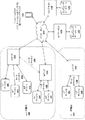
図1Bは、複数のIoTハブ110〜111、190に対する追加の接続オプションを例示する。この実施形態では、単一のユーザが、単一のユーザ構内180(例えば、ユーザの自宅又はビジネス)にオンサイトでインストールされた複数のハブ110〜111を有することができる。これは、例えば、IoTデバイス101〜105のすべてを接続するのに必要な無線範囲を拡張するために行われ得る。上述したように、ユーザが複数のハブ110、111を有する場合、それらは、ローカル通信チャネル(例えば、Wifi、イーサネット(登録商標)、電力線ネットワーキングなど)を介して接続されてもよい。一実施形態では、ハブ110〜111のそれぞれは、セルラー115又はWiFi 116接続(図1Bには明示されていない)を介してIoTサービス120への直接接続を確立することができる。代替的に、又は加えて、IoTハブ110などのIoTハブのうちの1つは、「マスター」ハブとして機能することができ、これは、IoTハブ111などのユーザ構内180上の他のすべてのIoTハブに接続性及び/又はローカルサービスを提供する(IoTハブ110とIoTハブ111を接続する点線で示すように)。例えば、マスターIoTハブ110は、IoTサービス120への直接接続を確立する唯一のIoTハブであってもよい。一実施形態では、「マスター」IoTハブ110のみに、IoTサービス120への接続を確立するためのセルラー通信インタフェースが備わっている。このように、IoTサービス120と他のIoTハブ111との間のすべての通信は、マスターIoTハブ110を通って流れる。この役割において、マスターIoTハブ110には、他のIoTハブ111とIoTサービス120との間で交換されるデータ(例えば、可能であれば、いくつかのデータ要求にローカルでサービスする)に対してフィルタリング動作を実行するための追加のプログラムコードが提供され得る。
FIG. 1B illustrates additional connection options for a plurality of IoT hubs 110-111, 190. In this embodiment, a single user can have multiple hubs 110-111 installed onsite in a single user premises 180 (eg, the user's home or business). This can be done, for example, to extend the radio range required to connect all of the IoT devices 101-105. As mentioned above, if a user has
IoTハブ110〜111がどのように接続されていようとも、一実施形態では、IoTサービス120は、ハブをユーザと論理的に関連付け、取り付けられたIoTデバイス101〜105のすべてを、インストールされたアプリケーション135(及び/又はブラウザベースのインタフェース)を有するユーザデバイスを介してアクセス可能な、単一の包括的なユーザインタフェースの下に結合する。
Regardless of how the IoT hubs 110-111 are connected, in one embodiment the
この実施形態では、マスターIoTハブ110及び1つ以上のスレーブIoTハブ111は、WiFiネットワーク116、イーサネット(登録商標)ネットワーク、及び/又は電力線通信(power-line communications)(PLC)ネットワーキング(例えば、ネットワークの全部若しくは一部がユーザの電力線を介して実行される)とすることができる、ローカルネットワークを介して接続してもよい。加えて、IoTハブ110〜111に対して、IoTデバイス101〜105のそれぞれは、いくつか例を挙げると、WiFi、イーサネット(登録商標)、PLC、又はBluetooth(登録商標) LEなどの、任意のタイプのローカルネットワークチャネルを使用して、IoTハブ110〜111と相互接続してもよい。
In this embodiment, the
図1Bはまた、第2のユーザ構内181にインストールされたIoTハブ190を示す。実質的に無制限の数のそのようなIoTハブ190は、世界中のユーザ構内のIoTデバイス191〜192からデータを収集するようにインストールされ、構成され得る。一実施形態では、2つのユーザ構内180〜181は、同じユーザに対して構成されてもよい。例えば、一方のユーザ構内180がユーザの基本的なホームであり、他方のユーザ構内181がユーザのバケーションホームであってもよい。そのような場合、IoTサービス120は、IoTハブ110〜111、190をユーザと論理的に関連付け、取り付けられたすべてのIoTデバイス101〜105、191〜192を、単一の包括的なユーザインタフェースの下に結合し、インストールされたアプリケーション135(及び/又はブラウザベースのインタフェース)を有するユーザデバイスを介してアクセス可能にする。
FIG. 1B also shows an
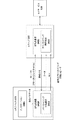
図2に例示するように、IoTデバイス101の例示的な実施形態は、プログラムコード及びデータ201〜203を記憶するメモリ210と、プログラムコードを実行しデータを処理する低電力マイクロコントローラ200とを含む。メモリ210は、ダイナミックランダムアクセスメモリ(dynamic random access memory)(DRAM)などの揮発性メモリであってもよいし、フラッシュメモリなどの不揮発性メモリであってもよい。一実施形態では、不揮発性メモリを永続記憶に使用し、揮発性メモリをプログラムコードの実行及びデータの実行に使用することができる。更に、メモリ210は、低電力マイクロコントローラ200内に統合されてもよく、バス又は通信ファブリックを介して低電力マイクロコントローラ200に連結されてもよい。本発明の根本的な原理は、メモリ210のいかなる特定の実装にも限定されない。
As illustrated in FIG. 2, an exemplary embodiment of the
例示したように、プログラムコードは、IoTデバイス101のアプリケーション開発者によって利用され得る既定のビルディングブロックのセットを含む、IoTデバイス201及びライブラリコード202によって実行される特定用途向けの機能セットを定義するアプリケーションプログラムコード203を含むことができる。一実施形態では、ライブラリコード202は、各IoTデバイス101とIoTハブ110との間の通信を可能にするための通信プロトコルスタック201などのIoTデバイスを実装するために必要とされる基本機能のセットを含む。上述したように、一実施形態では、通信プロトコルスタック201は、Bluetooth(登録商標) LEプロトコルスタックを含む。この実施形態では、Bluetooth(登録商標) LE無線機及びアンテナ207は、低電力マイクロコントローラ200内に統合されてもよい。しかしながら、本発明の基本原理は、いかなる特定の通信プロトコルにも限定されない。
As illustrated, the program code is an application that defines a purpose-built feature set executed by IoT device 201 and
図2に示す特定の実施形態はまた、ユーザ入力を受信し、ユーザ入力を低電力マイクロコントローラに提供する複数の入力デバイス又はセンサ210を含み、低電力マイクロコントローラは、アプリケーションコード203及びライブラリコード202に従ってユーザ入力を処理する。一実施形態では、入力デバイスのそれぞれは、エンドユーザにフィードバックを提供するLED 209を含む。
The particular embodiment shown in FIG. 2 also includes a plurality of input devices or
加えて、例示した実施形態は、低電力マイクロコントローラに電力を供給するための電池208を含む。一実施形態では、非充電式コイン型電池が使用される。しかしながら、別の実施形態では、統合された充電式電池を使用することができる(例えば、交流電源(図示せず)にIoTデバイスを接続することによって再充電可能)。 In addition, the illustrated embodiment includes a battery 208 for powering a low power microcontroller. In one embodiment, a non-rechargeable coin-cell battery is used. However, in another embodiment, an integrated rechargeable battery can be used (eg, rechargeable by connecting an IoT device to an AC power source (not shown)).
オーディオを発生するためのスピーカ205も設けられている。一実施形態では、低電力マイクロコントローラ299は、スピーカ205上にオーディオを発生するために圧縮されたオーディオストリーム(例えば、MPEG−4/アドバンストオーディオコーディング(Advanced Audio Coding)(AAC)ストリーム)を復号するための、オーディオ復号ロジックを含む。代替的に、低出力マイクロコントローラ200及び/又はアプリケーションコード/データ203が、ユーザが入力デバイス210を介して選択を入力すると、エンドユーザに口頭のフィードバックを提供するための、デジタルでサンプリングされたオーディオスニペットを含むことができる。
A
一実施形態では、IoTデバイス101が設計される特定用途に基づいて、1つ以上の他の/代替のI/Oデバイス又はセンサ250が、IoTデバイス101に含まれてもよい。例えば、温度、圧力、湿度などを測定するために環境センサを含めることができる。IoTデバイスがセキュリティデバイスとして使用される場合には、セキュリティセンサ及び/又はドアロックオープナが含まれてもよい。当然のことながら、これらの例は、単に例示のために提供されている。本発明の基本原理は、いかなる特定のタイプのIoTデバイスにも限定されない。実際に、ライブラリコード202が備わった低電力マイクロコントローラ200の高度にプログラマブルな性質を考慮すると、アプリケーション開発者は、新しいアプリケーションコード203及び新しいI/Oデバイス250を容易に開発して、実質的に任意のタイプのIoTアプリケーションのために低電力マイクロコントローラとインタフェースをとることができる。
In one embodiment, one or more other / alternative I / O devices or
一実施形態では、低電力マイクロコントローラ200はまた、通信を暗号化するための、及び/又は署名を生成するための暗号鍵を記憶するための安全な鍵ストアを含む。代替的に、鍵は、加入者識別モジュール(SIM)内に確保されてもよい。
In one embodiment, the
一実施形態では、実質的に電力を消費していない超低電力状態からIoTデバイスを起動させるために、ウェイクアップ受信機207が含まれる。一実施形態では、ウェイクアップ受信機207は、図3に示すように、IoTハブ110上に構成されたウェイクアップ送信機307から受信されたウェイクアップ信号に応答して、IoTデバイス101をこの低電力状態から出させるように構成される。具体的には、一実施形態では、送信機307と受信機207は共に、テスラコイルなどの電気共振トランス回路を形成する。動作中、ハブ110が非常に低い電力状態からIoTデバイス101を復帰させる必要がある場合、エネルギは送信機307から受信機207への無線周波数信号を介して送信される。エネルギ移動の理由で、IoTデバイス101は、それが低電力状態にあるときには、ハブからの信号を継続的に「聞く」必要がないので、実質的に電力を消費しないように構成することができる(ネットワーク信号を介してデバイスを起動させることができる、ネットワークプロトコルの場合と同様に)。むしろ、IoTデバイス101のマイクロコントローラ200は、送信機307から受信機207に電気的に送信されたエネルギを使用することによって、事実上パワーダウンされた後にウェイクアップするように構成することができる。
In one embodiment, the
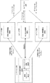
図3に例示するように、IoTハブ110はまた、プログラムコード及びデータ305を記憶するためのメモリ317と、プログラムコードを実行しデータを処理するためのマイクロコントローラなどのハードウェアロジック301とを含む。広域ネットワーク(wide area network)(WAN)インタフェース302及びアンテナ310は、IoTハブ110をセルラーサービス115に連結する。代替的に、上述したように、IoTハブ110は、ローカルエリアネットワーク通信チャネルを確立するためにWiFiインタフェース(及びWiFiアンテナ)又はイーサネット(登録商標)インタフェースなどのローカルネットワークインタフェース(図示せず)を含むこともできる。一実施形態では、ハードウェアロジック301はまた、通信を暗号化するための、及び/又は署名を生成/検証するための暗号鍵を記憶するための安全な鍵ストアを含む。代替的に、鍵は、加入者識別モジュール(SIM)内に確保されてもよい。
As illustrated in FIG. 3, the
ローカル通信インタフェース303及びアンテナ311は、IoTデバイス101〜105のそれぞれとのローカル通信チャネルを確立する。上述したように、一実施形態では、ローカル通信インタフェース303/アンテナ311はBluetooth(登録商標) LE規格を実装する。しかしながら、本発明の根底にある原理は、IoTデバイス101〜105とのローカル通信チャネルを確立するためのいかなる特定のプロトコルにも限定されない。図3においては別個のユニットとして示されているが、WANインタフェース302及び/又はローカル通信インタフェース303は、ハードウェアロジック301と同じチップ内に組み込まれてもよい。
The
一実施形態では、プログラムコード及びデータは、ローカル通信インタフェース303及びWANインタフェース302を介して通信するための別個のスタックを含むことができる通信プロトコルスタック308を含む。加えて、デバイスペアリングプログラムコード及びデータ306は、IoTハブを新しいIoTデバイスとペアリングすることができるようにメモリに記憶され得る。一実施形態では、各新しいIoTデバイス101〜105には、ペアリングプロセス中にIoTハブ110に通信される一意的なコードが割り当てられる。例えば、一意的なコードは、IoTデバイス上のバーコードに組み込まれてもよく、かつバーコードリーダ106によって読み取られてもよく、又はローカル通信チャネル130を介して通信されてもよい。別の実施形態では、一意的なIDコードがIoTデバイスに磁気的に組み込まれ、IoTハブは、無線周波数ID(radio frequency ID)(RFID)又は近距離通信(near field communication)(NFC)センサなどの磁気センサを有し、IoTデバイス101がIoTハブ110の数インチ内で移動するとき、コードを検出する。
In one embodiment, the program code and data include a
一実施形態では、一意的なIDが通信されると、IoTハブ110は、ローカルデータベース(図示せず)に問い合わせること、コードが許容可能であることを検証するためにハッシュを実行すること、並びに/又はIoTサービス120、ユーザデバイス135、及び/若しくはウェブサイト130と通信することによって、一意的なIDを検証して、IDコードの妥当性を確認することができる。妥当性が確認されると、一実施形態では、IoTハブ110は、IoTデバイス101をペアリングし、メモリ317(これは、上述したように、不揮発性メモリを含むことができる)にペアリングデータを記憶する。ペアリングが完了すると、IoTハブ110は、本明細書に記載の様々なIoT機能を実行するためにIoTデバイス101と接続することができる。
In one embodiment, when a unique ID is communicated, the
一実施形態では、IoTサービス120を実行する組織は、開発者が新しいIoTサービスを容易に設計できるように、IoTハブ110及び基本ハードウェア/ソフトウェアプラットフォームを提供することができる。具体的には、IoTハブ110に加えて、開発者には、ハブ110内で実行されるプログラムコード及びデータ305を更新するためのソフトウェア開発キット(software development kit)(SDK)が提供されてもよい。加えて、IoTデバイス101については、SDKは、様々な異なるタイプのアプリケーション101の設計を容易にするために、ベースのIoTハードウェア(例えば、低電力マイクロコントローラ200及び図2に示す他の構成要素)用に設計された広範なライブラリコード202のセットを含んでもよい。一実施形態では、SDKは、開発者がIoTデバイスの入力と出力を指定するだけでよいグラフィカルデザインインタフェースを含む。IoTデバイス101がハブ110及びサービス120に接続することを可能にする通信スタック201を含むネットワーキングコードはすべて、開発者のために既に配置されている。加えて、一実施形態では、SDKは、モバイルデバイス(例えば、iPhone(登録商標)及びAndroid(登録商標)デバイス)用のアプリケーションの設計を容易にするライブラリコードベースも含む。
In one embodiment, an organization running the
一実施形態では、IoTハブ110は、IoTデバイス101〜105とIoTサービス120との間のデータの連続的な双方向ストリームを管理する。IoTデバイス101〜105への/からの更新がリアルタイムで要求される状況(例えば、ユーザがセキュリティデバイス又は環境測定値の現在の状態を見る必要がある状況)では、IoTハブは、ユーザデバイス135及び/又は外部のウェブサイト130に定期的な更新を提供するためにオープンTCPソケットを維持することができる。更新を提供するために使用される特定のネットワーキングプロトコルは、基本用途のニーズに基づいて調整されてもよい。例えば、連続的な双方向ストリームを有することが理にかなっていない可能性がある場合、必要なときに情報を収集するために単純な要求/応答プロトコルを使用することができる。
In one embodiment, the
一実施形態では、IoTハブ110及びIoTデバイス101〜105の両方が、ネットワークを介して自動的に更新可能である。具体的には、IoTハブ110について新しい更新が利用可能であるとき、IoTサービス120から更新を自動的にダウンロードしてインストールすることができる。それは、古いプログラムコードを交換する前に、まず、更新されたコードをローカルメモリにコピーし、実行して、更新を検証し得る。同様に、IoTデバイス101〜105のそれぞれについて更新が利用可能である場合、更新は、IoTハブ110によって最初にダウンロードされ、IoTデバイス101〜105のそれぞれにプッシュアウトされてもよい。各IoTデバイス101〜105は、IoTハブに関して上述したのと同様の方法で更新を適用し、更新の結果をIoTハブ110に報告することができる。更新が成功した場合、IoTハブ110は、更新をそのメモリから削除し、(例えば、各IoTデバイスについての新しい更新を確認し続けることができるように)それぞれのIoTデバイスにインストールされているコードの最新バージョンを記録することができる。
In one embodiment, both the
一実施形態では、IoTハブ110は、A/C電力を介して給電される。具体的には、IoTハブ110は、A/C電源コードを介して供給されるA/C電圧をより低いDC電圧に変換するための変圧器を備えた電源ユニット390を含むことができる。
In one embodiment, the
図4Aは、IoTシステムを使用してユニバーサル遠隔制御操作を実行するための、本発明の一実施形態を例示する。具体的には、この実施形態では、IoTデバイス101〜103のセットには、(ほんの数例を挙げると)空気調節装置/ヒータ430、照明システム431、及び視聴覚機器432を含む、様々な異なるタイプの電子機器を制御する遠隔制御コードを送信するための、赤外線(infrared)(IR)及び/又は無線周波数(radio frequency)(RF)ブラスタ401〜403がそれぞれ備わっている。図4Aに示される実施形態では、IoTデバイス101〜103にはまた、以下に説明するように、それらが制御するデバイスの動作を検出するためのセンサ404〜406がそれぞれ備わっている。
FIG. 4A illustrates an embodiment of the invention for performing universal remote control operations using an IoT system. Specifically, in this embodiment, the set of IoT devices 101-103 includes a variety of different types (to name just a few), including an air conditioner / heater 430, a
例えば、IoTデバイス101におけるセンサ404は、現在の温度/湿度を検知し、それに応じて、現在の所望の温度に基づき空気調節装置/ヒータ430を制御するための温度及び/又は湿度センサであってもよい。この実施形態では、空気調節装置/ヒータ430は、遠隔制御デバイス(典型的には、それ自体が温度センサをその中に組み込んだ遠隔制御装置)を介して制御されるように設計されるものである。一実施形態では、ユーザは、ユーザデバイス135上にインストールされたアプリケーション又はブラウザを介して、所望の温度をIoTハブ110に提供する。IoTハブ110上で実行される制御ロジック412は、センサ404から現在の温度/湿度データを受信し、それに応じて、所望の温度/湿度に従ってIR/RFブラスタ401を制御するように、IoTデバイス101にコマンドを送信する。例えば、温度が所望の温度未満である場合、制御ロジック412は、温度を上げるように、IR/RFブラスタ401を介して空気調節装置/ヒータにコマンドを送信してもよい(例えば、空気調節装置をオフにすることか、又はヒータをオンにすることのいずれかによって)。コマンドは、IoTハブ110上のデータベース413に記憶された必要な遠隔制御コードを含んでもよい。代替的に、又は加えて、IoTサービス421は、指定されたユーザ選好及び記憶された制御コード422に基づき電子機器430〜432を制御するために、制御ロジック421を実装してもよい。
For example, the
例示した実施例におけるIoTデバイス102は、照明431を制御するために使用される。具体的には、IoTデバイス102のセンサ405は、照明設備431(又は他の照明装置)によってもたらされている光の現在の輝度を検出するように構成された光センサ又は光検出器であってもよい。ユーザは、ユーザデバイス135を介して、IoTハブ110に所望の照明レベル(オン又はオフの表示を含む)を指定してもよい。それに応答して、制御ロジック412は、照明431の現在の輝度レベルを制御するように、IR/RFブラスタ402にコマンドを送信する(例えば、現在の輝度が低すぎる場合は照明を明るくするか、若しくは現在の輝度が高すぎる場合は照明を暗くするか、又は単純に照明をオン若しくはオフにする)。
The
例示した実施例におけるIoTデバイス103は、視聴覚機器432(例えば、テレビ、A/V受信機、ケーブル/衛星受信機、AppleTVPP(商標)PPなど)を制御するように構成される。IoTデバイス103のセンサ406は、現在の周囲音量レベルを検出するためのオーディオセンサ(例えば、マイクロホン及び関連ロジック)、並びに/又はテレビによって生成された光に基づき、(例えば、指定されたスペクトル内の光を測定することによって)テレビがオンであるか、それともオフであるかを検出するための光センサであってもよい。代替的に、センサ406は、検出された温度に基づき、オーディオ機器がオンであるか、それともオフであるかを検出するための、視聴覚機器に接続された温度センサを含んでもよい。この場合も、ユーザデバイス135を介したユーザ入力に応答して、制御ロジック412は、IoTデバイス103のIRブラスタ403を介して視聴覚機器にコマンドを送信してもよい。
The
上記が本発明の一実施形態の単なる例示した実施例であることに留意すべきである。本発明の基本原理は、IoTデバイスによって制御されるいかなる特定のタイプのセンサ又は機器にも限定されない。 It should be noted that the above is merely an exemplary embodiment of one embodiment of the present invention. The basic principles of the invention are not limited to any particular type of sensor or device controlled by the IoT device.
IoTデバイス101〜103がBluetooth(登録商標) LE接続を介してIoTハブ110に連結される実施形態では、センサデータ及びコマンドは、Bluetooth(登録商標) LEチャネルを介して送信される。しかしながら、本発明の基本原理は、Bluetooth(登録商標) LE又はいずれの他の通信標準にも限定されない。
In an embodiment in which the IoT devices 101-103 are connected to the
一実施形態では、電子機器のそれぞれを制御するために必要とされる制御コードは、IoTハブ110上のデータベース413及び/又はIoTサービス120上のデータベース422に記憶される。図4Bに例示するように、制御コードは、IoTサービス120上で維持される異なる機器に対して、制御コード422のマスターデータベースからIoTハブ110に提供されてもよい。エンドユーザは、ユーザデバイス135上で実行されるアプリケーション又はブラウザを介して制御される電子(又は他の)機器のタイプを指定してもよく、それに応答して、IoTハブ上の遠隔制御コード学習モジュール491は、IoTサービス120上の遠隔制御コードデータベース492から、必要とされるIR/RFコードを取得してもよい(例えば、一意的なIDを有する各電子機器を識別する)。
In one embodiment, the control codes required to control each of the electronic devices are stored in
加えて、一実施形態では、IoTハブ110には、遠隔制御コード学習モジュール491が、電子機器と共に提供された元の遠隔制御装置495から直接新しい遠隔制御コードを「学習」することを可能にする、IR/RFインタフェース490が備わっている。例えば、空気調節装置430と共に提供された元の遠隔制御装置の制御コードが、遠隔制御データベースに含まれていない場合、ユーザは、ユーザデバイス135上のアプリケーション/ブラウザを介してIoTハブ110と対話して、元の遠隔制御装置によって生成される様々な制御コードをIoTハブ110に教えてもよい(例えば、温度を上げる、温度を下げるなど)。遠隔制御コードが学習されると、それらは、IoTハブ110上の制御コードデータベース413に記憶されてもよく、かつ/又は中央遠隔制御コードデータベース492に含められるように、IoTサービス120に送り返されてもよい(続いて、同じ空気調節装置ユニット430を有する他のユーザによって使用されてもよい)。
In addition, in one embodiment, the
一実施形態では、IoTデバイス101〜103のそれぞれは、極端に小さいフォームファクタを有し、両面テープ、小さい釘、磁気アタッチメントなどを使用して、それらの対応する電子機器430〜432の上又は付近に取り付けられてもよい。空気調節装置430などの1つの機器を制御するために、IoTデバイス101を十分に離して配置し、センサ404が自宅内の周囲温度を正確に測定することができるようにすることが望ましい(例えば、空気調節装置上に直接IoTデバイスを配置すると、温度測定値は、空気調節装置が作動しているときは低すぎになり、ヒータが作動しているときは高すぎになるであろう)。対照的に、照明を制御するために使用されるIoTデバイス102は、センサ405が現在の照明レベルを検出するために、照明設備431の上又は付近に配置されてもよい。
In one embodiment, each of the IoT devices 101-103 has an extremely small form factor and uses double-sided tape, small nails, magnetic attachments, etc. on or near their corresponding electronics 430-432. May be attached to. It is desirable to place the
記載される一般的な制御機能を提供することに加えて、IoTハブ110及び/又はIoTサービス120の一実施形態は、各電子機器の現在の状態に関連した通知をエンドユーザに送信する。通知は、テキストメッセージ及び/又はアプリケーション特有の通知であってもよく、次いで、通知は、ユーザのモバイルデバイス135のディスプレイ上に表示されてもよい。例えば、ユーザの空気調節装置が長期間オンであるが温度が変化していない場合、IoTハブ110及び/又はIoTサービス120は、空気調節装置が適切に機能していないという通知をユーザに送信してもよい。ユーザが自宅におらず(このことは、動作センサを介して検出されてもよく、若しくはユーザの現在の検出された位置に基づいてもよい)、センサ406が、視聴覚機器430がオンであることを示すか、又はセンサ405が、照明がオンであることを示す場合、ユーザが視聴覚機器432及び/又は照明431をオフにすることを希望するか尋ねる通知がユーザに送信されてもよい。同じタイプの通知が、任意の機器のタイプに対して送信されてもよい。
In addition to providing the general control functions described, one embodiment of the
ユーザが通知を受信すると、彼/彼女は、ユーザデバイス135上のアプリケーション又はブラウザを介して電子機器430〜432を遠隔制御してもよい。一実施形態では、ユーザデバイス135は、タッチスクリーンデバイスであり、アプリケーション又はブラウザは、機器430〜432を制御するためのユーザが選択可能なボタンを含む遠隔制御装置の画像を表示する。通知を受信した後、ユーザは、グラフィカル遠隔制御装置を開き、様々な異なる機器をオフにするか、又は調節してもよい。IoTサービス120を介して接続されている場合、ユーザの選択は、IoTサービス120からIoTハブ110に転送されてもよく、IoTハブ110は、次いで制御ロジック412を介して機器を制御することになる。代替的に、ユーザ入力は、ユーザデバイス135からIoTハブ110に直接送信されてもよい。
When the user receives the notification, he / she may remotely control the electronic device 430-432 via an application or browser on the
一実施形態では、ユーザは、電子機器430〜432に対して様々な自動制御機能を実行するように、IoTハブ110上の制御ロジック412をプログラミングしてもよい。上記の所望の温度、輝度レベル、及び音量レベルを維持することに加えて、制御ロジック412は、ある特定の条件が検出された場合に電子機器を自動的にオフにしてもよい。例えば、制御ロジック412が、ユーザが自宅にいないこと、及び空気調節装置が機能していないことを検出する場合、制御ロジック412は、空気調節装置を自動的にオフにしてもよい。同様に、ユーザが自宅におらず、センサ406が、視聴覚機器430がオンであることを示すか、又はセンサ405が、照明がオンであることを示す場合、制御ロジック412は、視聴覚機器及び照明をそれぞれオフにするように、IR/RFブラスタ403及び402を介してコマンドを自動的に送信してもよい。
In one embodiment, the user may program the
図5は、電子機器530及び531を監視するためのセンサ503及び504が備わった、IoTデバイス104及び105の追加の実施形態を例示する。具体的には、この実施形態のIoTデバイス104は、コンロがオンのままであるときを検出するためにコンロ530の上又は付近に配置されてもよい、温度センサ503を含む。一実施形態では、IoTデバイス104は、温度センサ503によって測定された現在の温度をIoTハブ110及び/又はIoTサービス120に送信する。コンロが閾値期間を超えてオンであることが検出される場合(例えば、測定された温度に基づき)、制御ロジック512は、コンロ530がオンであることをユーザに通知する通知を、エンドユーザのデバイス135に送信してもよい。加えて、一実施形態では、IoTデバイス104は、ユーザからの命令を受信することに応答して、又は自動的に(制御ロジック512がそうするようにユーザによってプログラミングされる場合)、のいずれかによって、コンロをオフにするための制御モジュール501を含んでもよい。一実施形態では、制御ロジック501は、コンロ530への電気又はガスを遮断するためのスイッチを備える。しかしながら、他の実施形態では、制御ロジック501は、コンロ自体内に統合されてもよい。
FIG. 5 illustrates an additional embodiment of
図5はまた、洗濯機及び/又は乾燥機などのある特定のタイプの電子機器の動作を検出するための動作センサ504を有する、IoTデバイス105を例示する。使用され得る別のセンサは、周囲の音量レベルを検出するためのオーディオセンサ(例えば、マイクロホン及びロジック)である。上記の他の実施形態のように、この実施形態は、ある特定の指定された条件が満たされた場合、エンドユーザに通知を送信してもよい(例えば、動作が長期間検出され、洗濯機/乾燥機がオフになっていないことを示す場合)。図5に示されないが、IoTデバイス105にはまた、自動的に、かつ/又はユーザ入力に応答して、(例えば、電気/ガスをオフに切り替えることによって)洗濯機/乾燥機531をオフにするための制御モジュールが備わっていてもよい。
FIG. 5 also illustrates an
一実施形態では、制御ロジック及びスイッチを有する第1のIoTデバイスは、ユーザの自宅内のすべての電力をオフにするように構成されてもよく、制御ロジック及びスイッチを有する第2のIoTデバイスは、ユーザの自宅内のすべてのガスをオフにするように構成されてもよい。次いで、センサを有するIoTデバイスは、ユーザの自宅内の電気又はガス駆動の機器の上又は付近に位置付けられてもよい。特定の機器がオンのままである(例えば、コンロ530)ことをユーザが通知された場合、ユーザは、自宅内のすべての電気又はガスをオフにするコマンドを送信して、損害を防止してもよい。代替的に、IoTハブ110及び/又はIoTサービス120の制御ロジック512は、そのような状況において電気又はガスを自動的にオフにするように構成されてもよい。
In one embodiment, the first IoT device with control logic and switch may be configured to turn off all power in the user's home, and the second IoT device with control logic and switch may be configured. , May be configured to turn off all gas in the user's home. The IoT device with the sensor may then be positioned on or near an electrical or gas driven device in the user's home. When the user is notified that a particular device remains on (eg stove 530), the user sends a command to turn off all electricity or gas in the home to prevent damage. May be good. Alternatively, the
一実施形態では、IoTハブ110及びIoTサービス120は、周期的な間隔で通信する。IoTサービス120が、IoTハブ110への接続が切れていることを検出する場合(例えば、指定された継続時間、IoTハブからの要求又は応答を受信していないことによって)、IoTサービス120は、この情報をエンドユーザのデバイス135に通信することになる(例えば、テキストメッセージ又はアプリケーション特有の通知を送信することによって)。
通信のための装置及び方法
中間デバイスを通じたデータ
In one embodiment, the
Devices and methods for communication Data through intermediate devices
上述したように、Bluetooth(登録商標) LEなどのIoTデバイスを相互接続するために使用される無線技術は概して、近距離技術であるため、IoT実装のためのハブがIoTデバイスの範囲外にある場合、IoTデバイスは、IoTハブにデータを送信することができない(逆もまた同様)。 As mentioned above, the radio technology used to interconnect IoT devices such as Bluetooth® LE is generally a short range technology, so hubs for IoT implementation are outside the scope of IoT devices. If so, the IoT device cannot send data to the IoT hub (and vice versa).
この欠陥に対処するために、本発明の一実施形態は、モバイルデバイスが範囲内にあるとき、1つ以上のモバイルデバイスと周期的に接続するために、IoTハブの無線範囲外にあるIoTデバイスのための機構を提供する。いったん接続されると、IoTデバイスは、IoTハブに提供される必要がある任意のデータをモバイルデバイスに送信することができ、次いでモバイルデバイスは、IoTハブにデータを転送する。 To address this flaw, one embodiment of the invention is an IoT device that is outside the radio range of an IoT hub to periodically connect to one or more mobile devices when the mobile device is within range. Provides a mechanism for. Once connected, the IoT device can send any data that needs to be provided to the IoT hub to the mobile device, which in turn transfers the data to the IoT hub.
図6に例示するように、一実施形態は、IoTハブ110と、IoTハブ110の範囲外にあるIoTデバイス601と、モバイルデバイス611とを含む。範囲外のIoTデバイス601は、データを収集及び通信することが可能な任意の形態のIoTデバイスを含んでもよい。例えば、IoTデバイス601は、冷蔵庫内の利用可能な食料品、食料品を消費するユーザ、及び現在の温度を監視するように、冷蔵庫内に構成されたデータ収集デバイスを備えてもよい。当然のことながら、本発明の基本原理は、いかなる特定のタイプのIoTデバイスにも限定されない。本明細書に記載される技術は、ほんの数例を挙げると、スマートメータ、コンロ、洗濯機、乾燥機、照明システム、HVACシステム、及び視聴覚機器に関するデータを収集及び送信するために使用されるデバイスを含む、任意のタイプのIoTデバイスを使用して実装されてもよい。
As illustrated in FIG. 6, one embodiment includes an
更に、動作中のモバイルデバイスである、図6に例示するIoTデバイス611は、データを通信及び記憶することが可能な任意の形態のモバイルデバイスであってもよい。例えば、一実施形態では、モバイルデバイス611は、本明細書に記載される技術を促進するために、アプリケーションがその上にインストールされたスマートフォンである。別の実施形態では、モバイルデバイス611は、ネックレス若しくはブレスレットに取り付けられた通信トークン、スマートウォッチ、又はフィットネスデバイスなど、装着可能なデバイスを含む。装着可能なトークンは、スマートフォンデバイスを所有しない高齢のユーザ又は他のユーザにとって特に有用であり得る。
Further, the
動作中、範囲外のIoTデバイス601は、モバイルデバイス611との接続性を周期的又は連続的にチェックしてもよい。接続を確立した後(例えば、ユーザが冷蔵庫の近くを移動する結果として)、IoTデバイス601上の任意の収集されたデータ605が、モバイルデバイス611上の一時データリポジトリ615に自動的に送信される。一実施形態では、IoTデバイス601及びモバイルデバイス611は、BTLEなどの低電力無線標準を使用して、ローカル無線通信チャネルを確立する。そのような場合、モバイルデバイス611は、既知のペアリング技術を使用してIoTデバイス601と最初にペアリングされてもよい。
During operation, the out-of-
いったんデータが一時データリポジトリに伝送されると、モバイルデバイス611は、IoTハブ110との通信が確立されるとデータを送信する(例えば、ユーザがIoTハブ110の範囲内を歩くとき)。次いで、IoTハブは、中央データリポジトリ413にデータを記憶してもよく、かつ/又はインターネット上で、1つ以上のサービス及び/若しくは他のユーザデバイスにデータを送信してもよい。一実施形態では、モバイルデバイス611は、異なるタイプの通信チャネルを使用して、IoTハブ110にデータを提供してもよい(潜在的に、WiFiなどのより高出力の通信チャネル)。
Once the data is transmitted to the temporary data repository, the
範囲外のIoTデバイス601、モバイルデバイス611、及びIoTハブはすべて、本明細書に記載される技術を実装するためのプログラムコード及び/又はロジックにより構成されてもよい。図7に例示するように、例えば、本明細書に記載される動作を実行するために、IoTデバイス601は、中間接続ロジック及び/又はアプリケーションにより構成されてもよく、モバイルデバイス611は、中間接続ロジック/アプリケーションにより構成されてもよく、IoTハブ110は、中間接続ロジック/アプリケーション721により構成されてもよい。各デバイス上の中間接続ロジック/アプリケーションは、ハードウェア、ソフトウェア、又はこれらの任意の組み合わせで実装されてもよい。一実施形態では、IoTデバイス601の中間接続ロジック/アプリケーション701は、モバイルデバイス上の中間接続ロジック/アプリケーション711(デバイスアプリケーションとして実装されてもよい)との接続を検索及び確立して、一時データリポジトリ615にデータを伝送する。次いで、モバイルデバイス611上の中間接続ロジック/アプリケーション701は、中央データリポジトリ413にデータを記憶するIoTハブ上の中間接続ロジック/アプリケーションに、データを転送する。
The out-of-
図7に例示するように、各デバイス上の中間接続ロジック/アプリケーション701、711、721は、手元のアプリケーションに基づき構成されてもよい。例えば、冷蔵庫に関して、接続ロジック/アプリケーション701は、周期的ベースで少数のパケットを送信するだけでよい。他のアプリケーション(例えば、温度センサ)に対して、接続ロジック/アプリケーション701は、より頻繁な更新を送信する必要があり得る。
As illustrated in FIG. 7, the intermediate connection logic /
モバイルデバイス611よりはむしろ、一実施形態では、IoTデバイス601が、IoTハブ110の範囲内に位置する1つ以上の中間IoTデバイスとの無線接続を確立するように構成されてもよい。この実施形態では、IoTハブの範囲外の任意のIoTデバイス601が、他のIoTデバイスを使用して「チェーン」を形成することによってハブにリンクされてもよい。
Rather than the
加えて、簡潔にするために、単一のモバイルデバイス611のみが図6〜7に例示されるが、一実施形態では、異なるユーザの複数のそのようなモバイルデバイスは、IoTデバイス601と通信するように構成されてもよい。更に、同じ技術が、複数の他のIoTデバイスに対して実装されてもよく、それにより、自宅全体にわたって中間デバイスデータ収集システムを形成する。
In addition, for brevity, only a single
更に、一実施形態では、本明細書に記載される技術は、様々な異なるタイプの関連データを収集するために使用されてもよい。例えば、一実施形態では、モバイルデバイス611がIoTデバイス601と接続するたびに、ユーザの識別が、収集されたデータ605と共に含まれてもよい。このようにして、IoTシステムは、自宅内の異なるユーザの挙動を追跡するために使用されてもよい。例えば、冷蔵庫内で使用される場合、収集されたデータ605は、冷蔵庫のそばを通る各ユーザ、冷蔵庫を開ける各ユーザ、及び各ユーザによって消費される特定の食料品の識別を含んでもよい。異なるタイプのデータが、他のタイプのIoTデバイスから収集されてもよい。このデータを使用して、システムは、例えば、どのユーザが衣服を洗濯するのか、どのユーザが所与の日にテレビを観るのか、各ユーザが就寝及び起床する時間などを判定することが可能である。次いで、このクラウドソースデータのすべてが、IoTハブのデータリポジトリ413内にコンパイルされてもよく、かつ/又は外部サービス若しくはユーザに転送されてもよい。
Further, in one embodiment, the techniques described herein may be used to collect a variety of different types of relevant data. For example, in one embodiment, each time the
本明細書に記載される技術の別の有益な用途は、補助を必要とし得る高齢のユーザを監視するためのものである。このアプリケーションに関して、モバイルデバイス611は、ユーザの自宅の異なる室内の情報を収集するために、高齢のユーザによって装着された非常に小型のトークンであってもよい。ユーザが冷蔵庫を開けるたびに、例えば、このデータは、収集されたデータ605と共に含まれ、トークンを介してIoTハブ110に伝送される。次いで、IoTハブは、1つ以上の外部ユーザ(例えば、高齢のユーザを世話する子供又は他の個人)にデータを提供してもよい。データが指定された期間(例えば、12時間)収集されていない場合、これは、高齢のユーザが自宅を動き回っていない、かつ/又は冷蔵庫を開けていないことを意味する。次いで、IoTハブ110又はIoTハブに接続された外部サービスは、これらの他の個人にアラート通知を送信し、彼らに高齢のユーザを確認するべきであることを通知してもよい。加えて、収集されたデータ605は、ユーザによって消費されている食品、並びに食料品店に行くことが必要であるかどうか、高齢のユーザがテレビを観ているかどうか、及びどれほど頻繁に観ているか、高齢のユーザが衣服を洗濯する頻度などの他の関連情報を含んでもよい。
Another useful use of the techniques described herein is for monitoring elderly users who may need assistance. For this application, the
別の実装例において、洗濯機、冷蔵庫、HVACシステムなどの電子デバイスに問題がある場合、収集されたデータは、交換される必要がある部品の指示を含んでもよい。そのような場合、通知は、問題を解決するための要求と共に技術者に送信されてもよい。次いで、技術者は、必要とされる交換部品を持って自宅に到着し得る。 In another implementation, if there is a problem with electronic devices such as washing machines, refrigerators, HVAC systems, the data collected may include instructions for parts that need to be replaced. In such cases, the notification may be sent to the technician with a request to resolve the problem. The technician can then arrive at home with the required replacement parts.
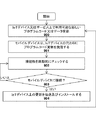
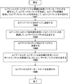
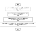
本発明の一実施形態に従った方法が図8に例示される。本方法は、上記のアーキテクチャとの関連で実装され得るが、いかなる特定のアーキテクチャにも限定されない。 A method according to an embodiment of the present invention is illustrated in FIG. The method may be implemented in the context of the architectures described above, but is not limited to any particular architecture.
801において、IoTハブの範囲外にあるIoTデバイスは、データ(例えば、冷蔵庫の扉の開放、使用された食料品など)を周期的に収集する。802において、IoTデバイスは、モバイルデバイスとの接続性を周期的又は連続的にチェックする(例えば、BTLE標準によって指定されたものなど、接続を確立するための標準的なローカル無線技術を使用して)。802において、モバイルデバイスへの接続が確立され、判定された場合、803において、収集されたデータは、803においてモバイルデバイスに伝送される。804において、モバイルデバイスは、IoTハブ、外部サービス、及び/又はユーザにデータを伝送する。述べられたように、モバイルデバイスは、それが既に接続されている場合(例えば、WiFiリンクを介して)、すぐにデータを送信し得る。 At 801 the IoT device outside the range of the IoT hub periodically collects data (eg, opening the refrigerator door, used groceries, etc.). At 802, the IoT device periodically or continuously checks connectivity with the mobile device (eg, using standard local radio techniques for establishing connectivity, such as those specified by the BTLE standard). ). If a connection to the mobile device is established and determined in 802, the collected data in 803 is transmitted to the mobile device in 803. At 804, mobile devices transmit data to IoT hubs, external services, and / or users. As mentioned, a mobile device can immediately send data if it is already connected (eg, via a WiFi link).
IoTデバイスからデータを収集することに加えて、一実施形態では、本明細書に記載される技術は、データを更新するか、又は別様にIoTデバイスにデータを提供するために使用されてもよい。一例が図9Aに示され、それは、IoTデバイス601(又はそのようなIoTデバイスの群)上にインストールされる必要があるプログラムコード更新901を有する、IoTハブ110を示す。プログラムコード更新は、システム更新、パッチ、構成データ、及びIoTデバイスがユーザの要求どおり動作するために必要とされる任意の他のデータを含んでもよい。一実施形態では、ユーザは、モバイルデバイス又はコンピュータを介してIoTデバイス601に対する構成オプションを指定してもよく、それらは次いで、本明細書に記載される技術を使用して、IoTハブ110上に記憶され、かつIoTデバイスに提供される。具体的には、一実施形態では、IoTハブ110上の中間接続ロジック/アプリケーション721は、モバイルデバイス611上の中間接続ロジック/アプリケーション711と通信して、一時記憶装置615内にプログラムコード更新を記憶する。モバイルデバイス611がIoTデバイス601の範囲に入るとき、モバイルデバイス611上の中間接続ロジック/アプリケーション711は、IoTデバイス601上の中間/接続ロジック/アプリケーション701と接続して、デバイスにプログラムコード更新を提供する。一実施形態では、IoTデバイス601は次いで、新しいプログラムコード更新及び/又はデータをインストールするための自動更新プロセスに入ってもよい。
In addition to collecting data from the IoT device, in one embodiment, the techniques described herein may be used to update the data or otherwise provide the data to the IoT device. good. An example is shown in FIG. 9A, which shows an
IoTデバイスを更新するための方法が、図9Bに示される。本方法は、上記のシステムアーキテクチャとの関連で実装され得るが、いかなる特定のシステムアーキテクチャにも限定されない。 A method for updating an IoT device is shown in FIG. 9B. The method may be implemented in the context of the system architecture described above, but is not limited to any particular system architecture.
900において、新しいプログラムコード又はデータ更新は、IoTハブ及び/又は外部サービス(例えば、インターネット上でモバイルデバイスに連結された)上で利用可能になる。901において、モバイルデバイスは、IoTデバイスの代わりにプログラムコード又はデータ更新を受信及び記憶する。IoTデバイス及び/又はモバイルデバイスは、902において接続が確立されているかどうかを判定するために周期的にチェックする。903において接続が確立され、判定された場合、904において、更新は、IoTデバイスに伝送され、インストールされる。
改善されたセキュリティのための実施形態
At 900, new program code or data updates will be available on IoT hubs and / or external services (eg, connected to mobile devices over the Internet). At 901, the mobile device receives and stores program code or data updates on behalf of the IoT device. IoT devices and / or mobile devices are periodically checked to determine if a connection is established at 902. If the connection is established and determined in 903, in 904 the update is transmitted to the IoT device and installed.
Embodiments for improved security
一実施形態では、各IoTデバイス101の低電力マイクロコントローラ200及びIoTハブ110の低電力ロジック/マイクロコントローラ301は、以下に記載される実施形態によって使用される暗号鍵を記憶するための安全な鍵ストアを含む(例えば、図10〜図15及び関連する文章を参照されたい)。代替的に、鍵は、後述するように、加入者識別モジュール(SIM)内に確保されてもよい。
In one embodiment, the
図10は、IoTサービス120、IoTハブ110、並びにIoTデバイス101及び102の間の通信を暗号化するために公開鍵インフラストラクチャ(public key infrastructure)(PKI)技術及び/又は対称鍵交換/暗号化技術を使用する、高レベルアーキテクチャを例示する。
FIG. 10 shows public key infrastructure (PKI) technology and / or symmetric key exchange / encryption for encrypting communications between
公開/秘密鍵ペアを使用する実施形態をまず説明し、続いて、対称鍵交換/暗号化技術を使用する実施形態を説明する。具体的には、PKIを使用するある実施形態において、一意的な公開/秘密鍵ペアが、各IoTデバイス101〜102、各IoTハブ110、及びIoTサービス120に関連付けられる。一実施形態では、新しいIoTハブ110がセットアップされるとき、その公開鍵がIoTサービス120に提供され、新しいIoTデバイス101がセットアップされるとき、その公開鍵がIoTハブ110及びIoTサービス120の両方に提供される。デバイス間で公開鍵を安全に交換するための様々な技術を以下に説明する。一実施形態では、いかなる受信デバイスも、署名の妥当性を確認することによって公開鍵の妥当性を検証することができるように、すべての公開鍵が、受信デバイスのすべてに既知である親鍵(すなわち、一種の証明書)によって署名される。したがって、未加工の公開鍵を単に交換するのではなく、むしろこれらの証明書が交換されることになる。
An embodiment using a public / private key pair will be described first, followed by an embodiment using a symmetric key exchange / encryption technique. Specifically, in certain embodiments using PKI, a unique public / private key pair is associated with each IoT device 101-102, each
例示したように、一実施形態では、各IoTデバイス101、102は、各デバイスの秘密鍵を記憶するセキュリティのために、それぞれ、安全な鍵ストア1001、1003を含む。次いで、セキュリティロジック1002、1304が、安全に記憶された秘密鍵を用いて、本明細書に記載される暗号化/解読動作を実行する。同様に、IoTハブ110は、IoTハブ秘密鍵、並びにIoTデバイス101〜102及びIoTサービス120の公開鍵を記憶するための安全な記憶装置1011、並びに、鍵を使用して暗号化/解読動作を実行するためのセキュリティロジック1012を含む。最後に、IoTサービス120は、それ自体の秘密鍵、様々なIoTデバイス及びIoTハブの公開鍵を記憶するセキュリティのための安全な記憶装置1021、並びに鍵を使用してIoTハブ及びデバイスとの通信を暗号化/解読するためのセキュリティロジック1013を含んでもよい。一実施形態では、IoTハブ110がIoTデバイスから公開鍵証明書を受信すると、IoTハブ110は、それを(例えば、上記の親鍵を使用して署名の妥当性を確認することにより)検証し、次いで、その中から公開鍵を抽出し、その公開鍵をその安全な鍵ストア1011内に記憶することができる。
As illustrated, in one embodiment, each
例として、一実施形態では、IoTサービス120が、コマンド又はデータ(例えば、ドアを開錠するコマンド、センサを読み取る要求、IoTデバイスにより処理/表示されるべきデータなど)をIoTデバイス101に送信する必要があるとき、セキュリティロジック1013は、IoTデバイス101の公開鍵を使用してそのデータ/コマンドを暗号化して、暗号化されたIoTデバイスパケットを生成する。一実施形態では、次いで、セキュリティロジック1013は、IoTハブ110の公開鍵を使用し、IoTデバイスパケットを暗号化して、IoTハブパケットを生成し、IoTハブパケットをIoTハブ110に送信する。一実施形態では、デバイス101が、それが信頼されるソースから変更されていないメッセージを受信していることを検証することができるように、サービス120は、その秘密鍵又は上述の親鍵を用いて、暗号化されたメッセージに署名する。次いで、デバイス101は、秘密鍵及び/又は親鍵に対応する公開鍵を使用して、署名の妥当性を確認してもよい。上述したように、対称鍵交換/暗号化技術が、公開/秘密鍵暗号化の代わりに使用されてもよい。これらの実施形態では、1つの鍵をプライベートに記憶し、対応する公開鍵を他のデバイスに提供するのではなく、それぞれのデバイスに、暗号化のために、かつ署名の妥当性を確認するために使用されるものと同じ対称鍵のコピーを提供してもよい。対称鍵アルゴリズムの一例は高度暗号化標準(Advanced Encryption Standard)(AES)であるが、本発明の基本原理は、いかなるタイプの特定の対称鍵にも限定されない。
As an example, in one embodiment, the
ある対称鍵実装形態を使用すると、各デバイス101は、IoTハブ110と対称鍵を交換するために、安全な鍵交換プロトコルに入る。動的対称鍵プロビジョニングプロトコル(Dynamic Symmetric Key Provisioning Protocol)(DSKPP)などの安全な鍵プロビジョニングプロトコルが、安全な通信チャネルを介して鍵を交換するために使用され得る(例えば、コメント要求(Request for Comments)(RFC)6063を参照されたい)。しかしながら、本発明の基本原理は、いかなる特定の鍵プロビジョニングプロトコルにも限定されるものではない。
Using certain symmetric key implementations, each
対称鍵が交換されると、それらは、各デバイス101及びIoTハブ110によって、通信を暗号化するために使用され得る。同様に、IoTハブ110及びIoTサービス120は、安全な対称鍵交換を実行し、次いで、交換された対称鍵を使用して通信を暗号化し得る。一実施形態では、新しい対称鍵が、デバイス101とハブ110との間、及びハブ110とIoTサービス120との間で定期的に交換される。一実施形態では、デバイス101、ハブ110、及びサービス120の間での新しい通信セッションのたびに、新しい対称鍵が交換される(例えば、通信セッションごとに新しい鍵が生成され、安全に交換される)。一実施形態では、IoTハブ内のセキュリティモジュール1012が信頼される場合、サービス120は、ハブセキュリティモジュール1312とセッション鍵を交渉し得、次いで、セキュリティモジュール1012が、各デバイス120とセッション鍵を交渉することになる。次いで、サービス120からのメッセージは、ハブセキュリティモジュール1012で解読及び検証され、その後、デバイス101への送信のために再暗号化される。
Once the symmetric keys have been exchanged, they can be used by each
一実施形態では、ハブセキュリティモジュール1012でのセキュリティ侵害を防止するために、1回限りの(恒久的な)インストール鍵が、インストール時にデバイス101とサービス120との間で交渉されてもよい。メッセージをデバイス101に送るとき、サービス120は、まずこのデバイスインストール鍵を用いて暗号化/MACし、次いでハブのセッション鍵を用いてそれを暗号化/MACし得る。次いで、ハブ110は、暗号化されたデバイスブロブを検証及び抽出し、それをデバイスに送ることになる。
In one embodiment, a one-time (permanent) installation key may be negotiated between the
本発明の一実施形態では、リプレイアタックを防止するためにカウンタ機構が実装される。例えば、デバイス101からハブ110へ(又は逆もまた同様)の連続する通信それぞれに、継続的に増加するカウンタ値が割り当てられ得る。ハブ110とデバイス101との両方がこの値を追跡し、デバイス間での連続する通信それぞれにおいてその値が正しいことを検証する。これと同じ技術が、ハブ110とサービス120との間に実装され得る。この方法でカウンタを使用すると、各デバイス間での通信を偽装することがより困難になるであろう(カウンタ値が誤ったものになるため)。しかしながら、これを用いずとも、サービスとデバイスとの間で共有されたインストール鍵は、すべてのデバイスに対するネットワーク(ハブ)規模の攻撃を防止するであろう。
In one embodiment of the invention, a counter mechanism is implemented to prevent replay attacks. For example, each continuous communication from
一実施形態では、公開/秘密鍵暗号化を使用するとき、IoTハブ110は、その秘密鍵を使用してIoTハブパケットを解読し、暗号化されたIoTデバイスパケットを生成し、それを、関連付けられたIoTデバイス101に送信する。次いで、IoTデバイス101は、その秘密鍵を使用してIoTデバイスパケットを解読して、IoTサービス120を起点とするコマンド/データを生成する。次いで、IoTデバイス101は、データを処理し、かつ/又はコマンドを実行してもよい。対称暗号化を使用すると、各デバイスは、共有された対称鍵を用いて暗号化及び解読を行う。いずれかの場合であれば、各送信デバイスはまた、受信デバイスがメッセージの信頼性を検証することができるように、その秘密鍵を用いてメッセージに署名してもよい。
In one embodiment, when using public / private key encryption, the
異なる鍵のセットが、IoTデバイス101からIoTハブ110への通信及びIoTサービス120への通信を暗号化するために使用されてもよい。例えば、ある公開/秘密鍵構成を使用すると、一実施形態では、IoTデバイス101上のセキュリティロジック1002が、IoTハブ110の公開鍵を使用して、IoTハブ110に送信されたデータパケットを暗号化する。次いで、IoTハブ110上のセキュリティロジック1012は、IoTハブの秘密鍵を使用して、データパケットを解読し得る。同様に、IoTデバイス101上のセキュリティロジック1002及び/又はIoTハブ110上のセキュリティロジック1012は、IoTサービス120の公開鍵を使用して、IoTサービス120に送信されたデータパケットを暗号化し得る(これは次いで、IoTサービス120上のセキュリティロジック1013によって、サービスの秘密鍵を使用して解読され得る)。対称鍵を使用すると、デバイス101及びハブ110は、ある対称鍵を共有し得、一方でハブ及びサービス120は、異なる対称鍵を共有し得る。
Different sets of keys may be used to encrypt the communication from the
上記の説明において、ある特定の具体的詳細が上に記載されているが、本発明の基本原理は様々な異なる暗号化技術を使用して実装され得ることに留意すべきである。例えば、上述した一部の実施形態は非対称の公開/秘密鍵ペアを使用するが、別の実施形態は、様々なIoTデバイス101〜102、IoTハブ110、及びIoTサービス120の間で安全に交換される対称鍵を使用し得る。更に、一部の実施形態では、データ/コマンド自体は暗号化されないが、データ/コマンド(又は他のデータ構造)上の署名を生成するために鍵が使用される。次いで、受信者が、その鍵を使用して署名の妥当性を確認し得る。
Although certain specific details are given above in the above description, it should be noted that the basic principles of the present invention can be implemented using a variety of different cryptographic techniques. For example, some embodiments described above use asymmetric public / private key pairs, while other embodiments securely exchange between various IoT devices 101-102,
図11に例示するように、一実施形態では、各IoTデバイス101上の安全な鍵ストアは、プログラマブル加入者識別モジュール(SIM)1101を使用して実装される。この実施形態では、IoTデバイス101は、IoTデバイス101上のSIMインタフェース1100内に据え付けられたプログラムされていないSIMカード1101と共にエンドユーザに最初に提供され得る。1つ以上の暗号鍵のセットを用いてSIMをプログラミングするために、ユーザは、プログラマブルSIMカード1101をSIMインタフェース500から取り出し、それをIoTハブ110上のSIMプログラミングインタフェース1102に挿入する。次いで、IoTハブ上のプログラミングロジック1125が、IoTデバイス101をIoTハブ110及びIoTサービス120に登録/ペアリングするように、SIMカード1101を安全にプログラミングする。一実施形態では、公開/秘密鍵ペアは、プログラミングロジック1125によってランダムに生成されてもよく、次いで、このペアの公開鍵は、IoTハブの安全な記憶デバイス411内に記憶されてもよく、一方で秘密鍵は、プログラマブルSIM 1101内に記憶されてもよい。加えて、プログラミングロジック525は、IoTハブ110、IoTサービス120、及び/又は任意の他のIoTデバイス101の公開鍵を、(IoTデバイス101上のセキュリティロジック1302による発信データの暗号化に使用するために)SIMカード1401上に記憶してもよい。いったんSIM 1101がプログラミングされると、新しいIoTデバイス101に、SIMを安全な識別子として使用して(例えば、SIMを用いてデバイスを登録するための既存の技術を使用して)IoTサービス120がプロビジョニングされ得る。プロビジョニング後、IoTハブ110とIoTサービス120との両方が、IoTデバイスの公開鍵のコピーを、IoTデバイス101との通信を暗号化する際に使用されるように安全に記憶する。
As illustrated in FIG. 11, in one embodiment, a secure keystore on each
図11に関して上述した技術は、新しいIoTデバイスをエンドユーザに提供する際に多大な柔軟性を提供する。(現在行われているのと同様に)ユーザが販売/購入の際に各SIMを特定のサービスプロバイダに直接登録することを要するのではなく、SIMは、エンドユーザによりIoTハブ110を介して直接プログラミングされてもよく、プログラミングの結果は、IoTサービス120に安全に通信され得る。それ故に、新しいIoTデバイス101がオンライン又はローカルの小売業者からエンドユーザに販売され、後にIoTサービス120が安全にプロビジョニングされ得る。
The techniques described above with respect to FIG. 11 provide a great deal of flexibility in providing new IoT devices to end users. Rather than requiring the user to register each SIM directly with a particular service provider at the time of sale / purchase (as is currently done), the SIM is directly by the end user via the
SIM(加入者識別モジュール)という具体的な文脈において登録及び暗号化技術を上述したが、本発明の基本原理は「SIM」デバイスに限定されない。むしろ、本発明の基本原理は、暗号鍵セットを記憶するための安全な記憶装置を有する、いかなるタイプのデバイスを使用して実装されてもよい。更に、上記の実施形態は取り外し可能なSIMデバイスを含むのに対し、一実施形態では、SIMデバイスは取り外し可能でないが、IoTデバイス自体が、IoTハブ110のプログラミングインタフェース1102に挿入されてもよい。
Although the registration and encryption techniques have been described above in the specific context of SIM (Subscriber Identification Module), the basic principles of the present invention are not limited to "SIM" devices. Rather, the basic principles of the invention may be implemented using any type of device that has a secure storage device for storing cryptographic key sets. Further, while the above embodiment includes a removable SIM device, in one embodiment the SIM device is not removable, but the IoT device itself may be inserted into the programming interface 1102 of the
一実施形態では、ユーザがSIM(又は他のデバイス)をプログラミングすることを要するのではなく、SIMは、エンドユーザへの流通前に、IoTデバイス101に予めプログラミングされる。この実施形態において、ユーザがIoTデバイス101をセットアップするとき、本明細書に記載される様々な技術が、IoTハブ110/IoTサービス120と新しいIoTデバイス101との間で暗号鍵を安全に交換するために使用され得る。
In one embodiment, the user is not required to program the SIM (or other device), the SIM is pre-programmed into the
例えば、図12Aに例示するように、各IoTデバイス101又はSIM 401は、IoTデバイス101及び/又はSIM 1001を一意的に識別するバーコード又はQRコード(登録商標)1501と共に梱包されていてもよい。一実施形態では、バーコード又はQRコード(登録商標)1201は、IoTデバイス101又はSIM 1001の公開鍵の符号化表現を含む。代替的に、バーコード又はQRコード(登録商標)1201は、IoTハブ110及び/又はIoTサービス120によって、公開鍵を識別又は生成するために使用されてもよい(例えば、安全な記憶装置内に既に記憶されている公開鍵に対するポインタとして使用される)。バーコード又はQRコード(登録商標)601は、別個のカード上に(図12Aに示されるように)印刷されてもよく、又はIoTデバイス自体上に直接印刷されてもよい。バーコードが印刷される場所に関わらず、一実施形態では、IoTハブ110には、バーコードを読み取り、得られたデータをIoTハブ110上のセキュリティロジック1012及び/又はIoTサービス120上のセキュリティロジック1013に提供するための、バーコードリーダ206が備わっている。次いで、IoTハブ110上のセキュリティロジック1012は、その安全な鍵ストア1011内にIoTデバイスの公開鍵を記憶してもよく、IoTサービス120上のセキュリティロジック1013は、その安全な記憶装置1021内に公開鍵を(後の暗号化通信に使用するために)記憶してもよい。
For example, as illustrated in FIG. 12A, each
一実施形態では、バーコード又はQRコード(登録商標)1201内に含まれるデータはまた、インストールされたIoTアプリケーション又はIoTサービスプロバイダにより設計されたブラウザベースのアプレットを用いて、ユーザデバイス135(例えば、iPhone(登録商標)又はAndroidデバイスなど)によりキャプチャされてもよい。キャプチャされると、バーコードデータは、安全な接続(例えば、セキュアソケットレイヤー(secure sockets layer)(SSL)接続など)を介して、IoTサービス120に安全に通信され得る。バーコードデータはまた、安全なローカル接続を介して(例えば、ローカルWiFi又はBluetooth(登録商標) LE接続を介して)、クライアントデバイス135からIoTハブ110に提供されてもよい。
In one embodiment, the data contained within the barcode or QR code® 1201 will also use a user device 135 (eg, eg, a browser-based applet designed by an installed IoT application or IoT service provider). It may be captured by an IoT® or an Applet device, etc.). Once captured, the barcode data can be securely communicated to the
IoTデバイス101上のセキュリティロジック1002及びIoTハブ110上のセキュリティロジック1012は、ハードウェア、ソフトウェア、ファームウェア、又はそれらの任意の組み合わせを使用して実装され得る。例えば、一実施形態では、セキュリティロジック1002、1012は、IoTデバイス101とIoTハブ110との間にローカル通信チャネル130を確立するために使用されるチップ(例えば、ローカルチャネル130がBluetooth(登録商標) LEである場合は、Bluetooth(登録商標) LEチップ)内に実装される。セキュリティロジック1002、1012の具体的な位置に関わらず、一実施形態では、セキュリティロジック1002、1012は、ある特定のタイプのプログラムコードを実行するために安全な実行環境を確立するように設計される。これは、例えば、TrustZone技術(一部のARMプロセッサで利用可能)及び/又はトラステッド・エグゼキューション・テクノロジー(Intelにより設計)を使用することによって、実装され得る。当然のことながら、本発明の基本原理は、いかなる特定のタイプの安全な実行技術にも限定されない。
The
一実施形態では、バーコード又はQRコード(登録商標)1501は、各IoTデバイス101をIoTハブ110とペアリングするために使用され得る。例えば、Bluetooth(登録商標) LEデバイスをペアリングするために現在使用されている標準的な無線ペアリングプロセスを使用するのではなく、バーコード又はQRコード(登録商標)1501内に組み込まれたペアリングコードをIoTハブ110に提供して、IoTハブを対応するIoTデバイスとペアリングしてもよい。
In one embodiment, a barcode or QR code® 1501 can be used to pair each
図12Bは、IoTハブ110上のバーコードリーダ206が、IoTデバイス101に関連付けられたバーコード/QRコード(登録商標)1201をキャプチャする、一実施形態を例示する。上述したように、バーコード/QRコード(登録商標)1201は、IoTデバイス101上に直接印刷されてもよく、又はIoTデバイス101と共に提供される別個のカード上に印刷されてもよい。いずれの場合においても、バーコードリーダ206は、バーコード/QRコード(登録商標)1201からペアリングコードを読み取り、このペアリングコードをローカル通信モジュール1280に提供する。一実施形態では、ローカル通信モジュール1280は、Bluetooth(登録商標) LEチップ及び関連付けられたソフトウェアであるが、本発明の基本原理は、いかなる特定のプロトコル標準にも限定されない。ペアリングコードが受信されると、それは、ペアリングデータ1285を含む安全な記憶装置内に記憶され、IoTデバイス101とIoTハブ110とが自動的にペアリングされる。この方法でIoTハブが新しいIoTデバイスとペアリングされるたびに、そのペアリングに関するペアリングデータが、安全な記憶装置685内に記憶される。一実施形態では、IoTハブ110のローカル通信モジュール1280がペアリングコードを受信すると、それは、このコードを鍵として使用して、ローカル無線チャネルを介したIoTデバイス101との通信を暗号化し得る。
FIG. 12B illustrates an embodiment in which the
同様に、IoTデバイス101側では、ローカル通信モジュール1590が、IoTハブとのペアリングを示すペアリングデータを、ローカルの安全な記憶デバイス1595内に記憶する。ペアリングデータ1295は、バーコード/QRコード(登録商標)1201で識別される予めプログラミングされたペアリングコードを含んでもよい。ペアリングデータ1295はまた、安全なローカル通信チャネルを確立するために必要な、IoTハブ110上のローカル通信モジュール1280から受信されるペアリングデータ(例えば、IoTハブ110との通信を暗号化するための追加の鍵)を含んでもよい。
Similarly, on the
したがって、バーコード/QRコード(登録商標)1201は、ペアリングコードが無線で送信されないため、現在の無線ペアリングプロトコルよりもはるかに安全な方法でローカルペアリングを実行するために使用され得る。加えて、一実施形態では、ペアリングに使用されるものと同じバーコード/QRコード(登録商標)1201を使用して暗号鍵を識別し、IoTデバイス101からIoTハブ110へ、かつIoTハブ110からIoTサービス120への安全な接続を構築することができる。
Therefore, barcode / QR code® 1201 can be used to perform local pairing in a much more secure manner than current wireless pairing protocols, as the pairing code is not transmitted wirelessly. In addition, in one embodiment, the same barcode / QR code® 1201 used for pairing is used to identify the encryption key from the
本発明の一実施形態によるSIMカードをプログラミングするための方法が、図13に例示される。本方法は、上述のシステムアーキテクチャ内で実装され得るが、いかなる特定のシステムアーキテクチャにも限定されない。 A method for programming a SIM card according to an embodiment of the present invention is illustrated in FIG. The method can be implemented within the system architecture described above, but is not limited to any particular system architecture.
1301において、ユーザは、空のSIMカードを備えた新しいIoTデバイスを受け取り、1602において、ユーザは、空のSIMカードをIoTハブに挿入する。1303において、ユーザは、1つ以上の暗号鍵のセットを用いて空のSIMカードをプログラミングする。例えば、上述のように、一実施形態において、IoTハブは、公開/秘密鍵ペアをランダムに生成し、秘密鍵をSIMカード上に、かつ公開鍵をそのローカルの安全な記憶装置内に記憶し得る。加えて、1304において、IoTデバイスを識別し、かつIoTデバイスとの暗号化通信を確立するために使用され得るように、少なくとも公開鍵がIoTサービスに送信される。上述したように、一実施形態では、「SIM」カード以外のプログラマブルデバイスが、図13に示される方法でSIMカードと同じ機能を実行するために使用されてもよい。 At 1301, the user receives a new IoT device with an empty SIM card, and at 1602, the user inserts an empty SIM card into the IoT hub. At 1303, the user programs an empty SIM card with one or more sets of cryptographic keys. For example, as described above, in one embodiment, the IoT hub randomly generates a public / private key pair and stores the private key on the SIM card and the public key in its local secure storage device. obtain. In addition, at 1304, at least a public key is transmitted to the IoT service so that it can be used to identify the IoT device and establish encrypted communication with the IoT device. As mentioned above, in one embodiment, a programmable device other than the "SIM" card may be used to perform the same functions as the SIM card in the manner shown in FIG.
新しいIoTデバイスをネットワークに統合するための方法が、図14に例示される。本方法は、上述のシステムアーキテクチャ内で実装され得るが、いかなる特定のシステムアーキテクチャにも限定されない。 A method for integrating a new IoT device into a network is illustrated in FIG. The method can be implemented within the system architecture described above, but is not limited to any particular system architecture.
1401において、ユーザは、暗号鍵が予め割り当てられている新しいIoTデバイスを受け取る。1402において、この鍵がIoTハブに安全に提供される。上述のように、一実施形態では、これは、IoTデバイスに関連付けられたバーコードを読み取って、デバイスに割り当てられた公開/秘密鍵ペアの公開鍵を識別することを伴う。バーコードは、IoTハブによって直接読み取られても、又はアプリケーション若しくはブラウザを介してモバイルデバイスによってキャプチャされてもよい。別の実施形態では、Bluetooth(登録商標) LEチャネル、近距離通信(NFC)チャネル、又は安全なWiFiチャネルなどの安全な通信チャネルが、鍵の交換のためにIoTデバイスとIoTハブとの間に確立されてもよい。鍵の送信方法に関わらず、受信されると、鍵はIoTハブデバイスの安全な鍵ストア内に記憶される。上述のように、セキュアエンクレーブ、トラステッド・エグゼキューション・テクノロジー(Trusted Execution Technology)(TXT)、及び/又はTrustzoneなどの様々な安全な実行技術が、鍵の記憶及び保護のためにIoTハブで使用され得る。加えて、803において、鍵はIoTサービスに安全に送信され、IoTサービスは、この鍵をそれ自体の安全な鍵ストア内に記憶する。IoTサービスは次いで、この鍵を使用して、IoTデバイスとの通信を暗号化し得る。この場合も、この交換は、証明書/署名付き鍵を使用して実行されてもよい。ハブ110内では、記憶された鍵の改変/追加/除去を防止することが特に重要である。
At 1401, the user receives a new IoT device with a pre-assigned encryption key. At 1402, this key is securely provided to the IoT hub. As mentioned above, in one embodiment, this involves scanning the barcode associated with the IoT device to identify the public key of the public / private key pair assigned to the device. Barcodes may be read directly by the IoT hub or captured by a mobile device via an application or browser. In another embodiment, a secure communication channel, such as a Bluetooth® LE channel, Near Field Communication (NFC) channel, or secure WiFi channel, is between the IoT device and the IoT hub for key exchange. It may be established. Upon receipt, the key is stored in the secure keystore of the IoT hub device, regardless of how the key is transmitted. As mentioned above, various secure execution technologies such as Secure Enclave, Trusted Execution Technology (TXT), and / or Trustzone are used in IoT hubs for key storage and protection. Can be done. In addition, at 803, the key is securely transmitted to the IoT service, which stores the key in its own secure keystore. The IoT service can then use this key to encrypt communication with the IoT device. Again, this exchange may be performed using a certificate / signed key. Within the
公開/秘密鍵を使用してコマンド/データをIoTデバイスに安全に通信するための方法が、図15に例示される。本方法は、上述のシステムアーキテクチャ内で実装され得るが、いかなる特定のシステムアーキテクチャにも限定されない。 A method for securely communicating commands / data to an IoT device using a public / private key is illustrated in FIG. The method can be implemented within the system architecture described above, but is not limited to any particular system architecture.
1501において、IoTサービスは、IoTデバイス公開鍵を使用してデータ/コマンドを暗号化して、IoTデバイスパケットを作成する。次いで、IoTサービスは、IoTハブの公開鍵を使用し、このIoTデバイスパケットを暗号化して、IoTハブパケットを作成する(例えば、IoTデバイスパケット周囲のIoTハブラッパーを作成する)。1502において、IoTサービスは、IoTハブパケットをIoTハブに送信する。1503において、IoTハブは、IoTハブの秘密鍵を使用してIoTハブパケットを解読して、IoTデバイスパケットを生成する。次いで、1504において、IoTハブは、IoTデバイスパケットをIoTデバイスに送信し、IoTデバイスは、1505において、IoTデバイス秘密鍵を使用してIoTデバイスパケットを解読して、データ/コマンドを生成する。1506において、IoTデバイスは、データ/コマンドを処理する。 At 1501, the IoT service uses the IoT device public key to encrypt data / commands to create IoT device packets. The IoT service then uses the IoT hub's public key to encrypt this IoT device packet to create an IoT hub packet (eg, create an IoT hub wrapper around the IoT device packet). At 1502, the IoT service sends an IoT hub packet to the IoT hub. At 1503, the IoT hub uses the IoT hub's private key to decrypt the IoT hub packet and generate an IoT device packet. Then, at 1504, the IoT hub sends the IoT device packet to the IoT device, and at 1505, the IoT device decrypts the IoT device packet using the IoT device private key to generate data / commands. At 1506, the IoT device processes data / commands.
対称鍵を使用するある実施形態において、対称鍵交換は、各デバイス間(例えば、各デバイスとハブと、及びハブとサービスとの間)で交渉され得る。鍵交換が完了すると、各送信デバイスは、対称鍵を使用して各送信を暗号化し、かつ/又はそれに署名し、その後、データを受信デバイスに送信する。
モノのインターネット(IoT)システムに安全な通信を確立するための装置及び方法
In certain embodiments that use symmetric keys, symmetric key exchanges can be negotiated between each device (eg, between each device and hub, and between hub and service). When the key exchange is complete, each transmitting device encrypts and / or signs each transmission using a symmetric key and then transmits the data to the receiving device.
Devices and methods for establishing secure communication with Internet of Things (IoT) systems
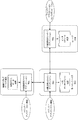
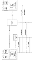
本発明の一実施形態では、通信チャネルをサポートするために使用される中間デバイス(例えば、ユーザのモバイルデバイス611及び/又はIoTハブ110など)に関わらず、データの暗号化及び解読は、IoTサービス120と各IoTデバイス101との間で実行される。IoTハブ110を介して通信する一実施形態が図16Aに例示され、IoTハブを必要としない別の実施形態が図16Bに例示される。
In one embodiment of the invention, data encryption and decryption is an IoT service, regardless of the intermediate device used to support the communication channel (eg, the user's
最初に図16Aで、IoTデバイス101とIoTサービス120との間の通信を暗号化/解読するために、IoTサービス120は、「サービスセッション鍵」1650のセットを管理する暗号化エンジン1660を含み、各IoTデバイス101は、「デバイスセッション鍵」1651のセットを管理する暗号化エンジン1661を含む。暗号化エンジンは、本明細書に記載するセキュリティ/暗号化技術を実行するとき、セッション公開/秘密鍵ペアを生成して、このペアのセッション秘密鍵へのアクセスを防止するための(他のものの中でも)ハードウェアセキュリティモジュール1630〜1631、及び導出したシークレットを使用してキーストリームを生成するためのキーストリーム生成モジュール1640〜1641を含む、異なるハードウェアモジュールに依拠することができる。一実施形態では、サービスセッション鍵1650及びデバイスセッション鍵1651は、関連する公開/秘密鍵ペアを含む。例えば、一実施形態では、IoTデバイス101上のデバイスセッション鍵1651は、IoTサービス120の公開鍵、及びIoTデバイス101の秘密鍵を含む。以下に詳細に説明するように、一実施形態では、安全な通信セッションを確立するために、セッション公開/秘密鍵ペア1650及び1651がそれぞれの暗号化エンジン、それぞれ1660及び1661によって使用されて、同じシークレットを生成し、このシークレットは次にSKGM 1640〜1641によって使用されて、IoTサービス120とIoTデバイス101との間の通信を暗号化及び解読するキーストリームを生成する。本発明の一実施形態によるシークレットの生成及び使用に関連付けられた追加の詳細は、以下に提供される。
First, in FIG. 16A, to encrypt / decrypt the communication between the
図16Aで、鍵1650〜1651を使用してシークレットが生成されると、クライアントは、クリアトランザクション1611によって示されるように常にIoTサービス120を介してIoTデバイス101にメッセージを送信することになる。本明細書で使用されるとき「クリア」は、根本的なメッセージが本明細書に記載された暗号化技術を使用して暗号化されていないことを示すことを意味する。しかし、例示したように、一実施形態では、セキュアソケットレイヤー(SSL)チャネル又は他の安全なチャネル(例えば、インターネットプロトコルセキュリティ(Internet Protocol Security)(IPSEC)チャネル)は、通信を保護するためにクライアントデバイス611とIoTサービス120との間で確立される。IoTサービス120上の暗号化エンジン1660は、次に、生成されたシークレットを使用してメッセージを暗号化して、1602で暗号化メッセージをIoTハブ110に送信する。メッセージを直接暗号化するためにシークレットを使用するのではなく、一実施形態では、シークレット及びカウンタ値を使用して、キーストリームを生成し、このキーストリームを使用して、それぞれのメッセージパケットを暗号化する。この実施形態の詳細は、図17に関して以下に説明する。
In FIG. 16A, when a secret is generated using keys 1650 to 1651, the client will always send a message to the
例示したように、SSL接続又は他の安全なチャネルは、IoTサービス120とIoTハブ110との間で確立することができる。IoTハブ110(一実施形態ではメッセージを解読する能力を有さない)は、1603で(例えば、Bluetooth(登録商標) Low Energy(BTLE)通信チャネルを介して)暗号化メッセージをIoTデバイスに送信する。IoTデバイス101上の暗号化エンジン1661は、次に、シークレットを使用してメッセージを解読して、メッセージコンテンツを処理することができる。キーストリームを生成するためにシークレットを使用する実施形態では、暗号化エンジン1661は、シークレット及びカウンタ値を使用してキーストリームを生成し、次にメッセージパケットの解読のためにキーストリームを使用することができる。
As illustrated, an SSL connection or other secure channel can be established between the
メッセージ自体は、IoTサービス120とIoTデバイス101との間の任意の形態の通信を含むことができる。例えば、メッセージは、測定を行ってその結果をクライアントデバイス611に通知して返すことなどの特定の機能を実行することをIoTデバイス101に命令するコマンドパケットを含むことができる、又はIoTデバイス101の動作を構成する構成データを含むことができる。
The message itself can include any form of communication between the
応答が必要とされる場合、IoTデバイス101上の暗号化エンジン1661は、シークレット又は導出されたキーストリームを使用して、応答を暗号化し、1604で暗号化応答をIoTハブ110に送信し、IoTハブ110は、1605で応答をIoTサービス120に転送する。IoTサービス120上の暗号化エンジン1660は、次に、シークレット又は導出されたキーストリームを使用して応答を解読して、1606で(例えば、SSL又は他の安全な通信チャネルを介して)解読された応答をクライアントデバイス611に送信する。
When a response is required, the encryption engine 1661 on the
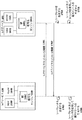
図16Bは、IoTハブを必要としない実施形態を例示する。むしろ、この実施形態では、IoTデバイス101とIoTサービス120との間の通信は、クライアントデバイス611を介して行われる(例えば、図6〜9Bに関して上述した実施形態におけるように)。この実施形態では、メッセージをIoTデバイス101に送信するために、クライアントデバイス611は、1611でメッセージの非暗号化バージョンをIoTサービス120に送信する。暗号化エンジン1660は、シークレット又は導出されたキーストリームを使用してメッセージを暗号化して、1612で暗号化メッセージをクライアントデバイス611に返送する。クライアントデバイス611は、次に、1613で暗号化メッセージをIoTデバイス101に転送し、暗号化エンジン1661は、シークレット又は導出されたキーストリームを使用してメッセージを解読する。IoTデバイス101は、次に、本明細書に記載されたようにメッセージを処理することができる。応答が必要とされる場合、暗号化エンジン1661は、シークレットを使用して、応答を暗号化し、1614で暗号化応答をクライアントデバイス611に送信し、クライアントデバイス611は、1615で暗号化応答をIoTサービス120に転送する。暗号化エンジン1660は、次に、応答を解読して、1616で解読された応答をクライアントデバイス611に送信する。
FIG. 16B illustrates an embodiment that does not require an IoT hub. Rather, in this embodiment, communication between the
図17は、IoTサービス120とIoTデバイス101との間で最初に実行することができる鍵交換及びキーストリーム生成を例示する。一実施形態では、この鍵交換は、IoTサービス120及びIoTデバイス101が新しい通信セッションを確立するたびに実行することができる。代替的に、鍵交換を実行することができ、交換されたセッション鍵を指定された期間(例えば、一日、一週間など)使用することができる。簡潔にするために図17に中間デバイスは示されていないが、通信は、IoTハブ110及び/又はクライアントデバイス611を介して行うことができる。
FIG. 17 illustrates key exchange and key stream generation that can first be performed between the
一実施形態では、IoTサービス120の暗号化エンジン1660は、セッション公開/秘密鍵ペアを生成するために、コマンドをHSM 1630(例えば、Amazon(登録商標)によって提供されるCloudHSMなどとすることができる)に送信する。HSM 1630は、その後、このペアのセッション秘密鍵へのアクセスを防止することができる。同様に、IoTデバイス101上の暗号化エンジンは、セッション公開/秘密鍵ペアを生成してこのペアのセッション秘密鍵へのアクセスを防止するHSM 1631(例えば、Atmel Corporation(登録商標)によるAtecc508 HSMなどの)にコマンドを送信することができる。当然のことながら、本発明の基本原理は、いかなる特定のタイプの暗号化エンジン又は製造業者にも限定されない。
In one embodiment, the encryption engine 1660 of the
一実施形態では、IoTサービス120は、1701で、HSM 1630を使用して生成されたそのセッション公開鍵をIoTデバイス101に送信する。IoTデバイスは、そのHSM 1631を使用して、それ自体のセッション公開/秘密鍵ペアを生成し、1702でそのペアの公開鍵をIoTサービス120に送信する。一実施形態では、暗号化エンジン1660〜1661は、楕円曲線Diffie−Hellman(Elliptic curve Diffie-Hellman)(ECDH)プロトコルを使用し、このプロトコルは、楕円曲線公開−秘密鍵ペアを有する2つの当事者が共有シークレットを確立することができる匿名鍵の取り決めである。一実施形態では、これらの技術を使用して、1703で、IoTサービス120の暗号化エンジン1660は、IoTデバイスセッション公開鍵及びそれ自体のセッション秘密鍵を使用してシークレットを生成する。同様に、1704で、IoTデバイス101の暗号化エンジン1661は、IoTサービス120のセッション公開鍵及びそれ自体のセッション秘密鍵を使用して同じシークレットを独自に生成する。より具体的には、一実施形態では、IoTサービス120上の暗号化エンジン1660は、シークレット=IoTデバイスセッション公開鍵*IoTサービスセッション秘密鍵という式に従って、シークレットを生成し、ここで(*)は、IoTデバイスセッション公開鍵がIoTサービスセッション秘密鍵によって点乗積されることを意味する。IoTデバイス101上の暗号化エンジン1661は、シークレット=IoTサービスセッション公開鍵*IoTデバイスセッション秘密鍵という式に従って、シークレットを生成し、IoTサービスセッション公開鍵は、IoTデバイスセッション秘密鍵によって点乗積される。結局、IoTサービス120及びIoTデバイス101は両方とも、以下に説明するように通信を暗号化するのに使用される同じシークレットを生成した。一実施形態では、暗号化エンジン1660〜1661は、シークレットを生成するための上記の動作を実行するKSGM、それぞれ1640〜1641などのハードウェアモジュールに依拠する。
In one embodiment, the
シークレットが決定されると、シークレットは、暗号化エンジン1660及び1661によって使用されて、データを直接暗号化及び解読することができる。代替的に、一実施形態では、暗号化エンジン1660〜1661は、コマンドをKSGM 1640〜1641に送信して、それぞれのデータパケットを暗号化/解読するためにシークレットを使用して新しいキーストリームを生成する(すなわち、それぞれのパケットに対して新しいキーストリームデータ構造が生成される)。具体的には、キーストリーム生成モジュール1640〜1641の一実施形態は、それぞれのデータパケットに対してカウンタ値が増加され、キーストリームを生成するためにシークレットと組み合わせて使用される、Galois/カウンタモード(Galois/Counter Mode)(GCM)を実装する。したがって、データパケットをIoTサービス120に送信するために、IoTデバイス101の暗号化エンジン1661は、シークレット及び現在のカウンタ値を使用して、KSGM 1640〜1641に新しいキーストリームを生成させ、次のキーストリームを生成するためにカウンタ値を増加させる。次に、新たに生成されたキーストリームを使用して、データパケットを暗号化し、その後、IoTサービス120に送信される。一実施形態では、キーストリームは、データでXORされて、暗号化データパケットを生成する。一実施形態では、IoTデバイス101は、カウンタ値を暗号化データパケットと共にIoTサービス120に送信する。IoTサービス上の暗号化エンジン1660は、次に、KSGM 1640と通信し、KSGM 1640は、受信したカウンタ値及びシークレットを使用して、キーストリーム(同じシークレット及びカウンタ値が使用されるので同じキーストリームでなければならない)を生成し、生成されたキーストリームを使用して、データパケットを解読する。
Once the secret is determined, it can be used by the encryption engines 1660 and 1661 to directly encrypt and decrypt the data. Alternatively, in one embodiment, the encryption engines 1660 to 1661 send commands to
一実施形態では、IoTサービス120からIoTデバイス101に送信されるデータパケットは、同じ方法で暗号化される。具体的には、それぞれのデータパケットに対してカウンタが増加されて、シークレットと共に使用されて、新しいキーストリームを生成する。キーストリームは、次に、データを暗号化するために使用され(例えば、データ及びキーストリームのXORを実行して)、暗号化データパケットは、カウンタ値と共にIoTデバイス101に送信される。IoTデバイス101上の暗号化エンジン1661は、次に、KSGM 1641と通信し、KSGM 1641は、カウンタ値及びシークレットを使用して、データパケットを解読するために使用される同じキーストリームを生成する。したがって、この実施形態では、暗号化エンジン1660〜1661は、それら自体のカウンタ値を使用して、データを暗号化するキーストリームを生成し、暗号化データパケットと共に受信したカウンタ値を使用して、データを解読するキーストリームを生成する。
In one embodiment, the data packet transmitted from the
一実施形態では、それぞれの暗号化エンジン1660〜1661は、それが他方から受信した最後のカウンタ値を追跡し、カウンタ値がシーケンス外で受信されたか否か又は同じカウンタ値が1回より多く受信されたか否かを検出するシーケンシングロジックを含む。カウンタ値がシーケンス外で受信された場合、又は同じカウンタ値が1回より多く受信された場合、これは、リプレイアタックが試みられていることを示し得る。それに応答して、暗号化エンジン1660〜1661は、通信チャネルから接続を切ることができる、及び/又はセキュリティアラートを生成することができる。 In one embodiment, each crypto engine 1660 to 1661 tracks the last counter value it received from the other and whether the counter value was received out of sequence or the same counter value received more than once. Includes sequencing logic to detect if it has been done. If the counter value is received out of sequence, or if the same counter value is received more than once, this may indicate that a replay attack is being attempted. In response, the encryption engines 1660 to 1661 can disconnect from the communication channel and / or generate security alerts.
図18は、4バイトのカウンタ値1800と、可変サイズの暗号化データフィールド1801と、6バイトのタグ1802とを含む、本発明の一実施形態で用いられる例示的な暗号化データパケットを例示する。一実施形態では、タグ1802は、解読されたデータ(それが解読されたら)の妥当性を確認するチェックサム値を含む。
FIG. 18 illustrates an exemplary encrypted data packet used in one embodiment of the invention, including a 4-
上述したように、一実施形態では、IoTサービス120とIoTデバイス101との間で交換されたセッション公開/秘密鍵ペア1650〜1651は、定期的に、及び/又はそれぞれの新しい通信セッションの開始に応答して生成することができる。
As mentioned above, in one embodiment, the session public / private key pairs 1650 to 1651 exchanged between the
本発明の一実施形態は、IoTサービス120とIoTデバイス101との間のセッションを認証するための追加の技術を実装する。具体的には、一実施形態では、親鍵ペア、工場鍵ペアのセット、並びにIoTサービス鍵ペアのセット及びIoTデバイス鍵ペアのセットを含む、公開/秘密鍵ペアの階層が使用される。一実施形態では、親鍵ペアは、他の鍵ペアのすべてに対する信頼のルートを含み、単一の高度に安全な場所に(例えば、本明細書に記載されたIoTシステムを実装する組織の管理下に)維持される。マスター秘密鍵を使用して、工場鍵ペアなどの様々な他の鍵ペアの上に署名を生成する(及びそれによって認証する)ことができる。署名は、次に、マスター公開鍵を使用して検証することができる。一実施形態では、IoTデバイスを製造するそれぞれの工場は、それ自体の工場鍵ペアを割り当てられ、工場鍵ペアは、次に、IoTサービス鍵及びIoTデバイス鍵を認証するために使用することができる。例えば、一実施形態では、工場秘密鍵を使用して、IoTサービス公開鍵及びIoTデバイス公開鍵の上に署名を生成する。これらの署名は、次に、対応する工場公開鍵を使用して検証することができる。これらのIoTサービス/デバイス公開鍵は、図16A〜Bに関して上述した「セッション」公開/秘密鍵と同じではないことに留意されたい。上述したセッション公開/秘密鍵は、一時的であり(すなわち、サービス/デバイスセッションに対して生成される)、一方、IoTサービス/デバイス鍵ペアは、恒久的なものである(すなわち、工場で生成される)。
One embodiment of the invention implements an additional technique for authenticating a session between the
親鍵、工場鍵、サービス/デバイス鍵の間の上述の関係を念頭に、本発明の一実施形態は、IoTサービス120とIoTデバイス101との間の認証及びセキュリティの追加のレイヤを提供するために、以下の動作を実行する。
A.一実施形態では、IoTサービス120は、最初に、以下を含むメッセージを生成する。
1.IoTサービスの一意的なID:
・IoTサービスのシリアルナンバー、
・タイムスタンプ、
・この一意的なIDに署名するために使用される工場鍵のID、
・一意的なID(すなわち、サービス)のクラス、
・IoTサービスの公開鍵、
・一意的なIDの上の署名。
2.以下を含む工場証明書:
・タイムスタンプ、
・証明書に署名するために使用される親鍵のID、
・工場公開鍵、
・工場証明書の署名。
3.IoTサービスセッション公開鍵(図16A〜Bに関して上述したような)
4.IoTサービスセッション公開鍵署名(例えば、IoTサービスの秘密鍵で署名された)。
B.一実施形態では、メッセージは、交渉チャネル(以下に説明する)上でIoTデバイスに送信される。IoTデバイスは、メッセージを解析して:
1.工場証明書の署名(メッセージペイロード内に存在する場合のみ)を検証する。
2.一意的なIDによって識別された鍵を使用して一意的なIDの署名を検証する。
3.一意的なIDからのIoTサービスの公開鍵を使用してIoTサービスセッション公開鍵署名を検証する。
4.IoTサービスの公開鍵、並びにIoTサービスのセッション公開鍵を保存する。
5.IoTデバイスセッション鍵ペアを生成する。
C.IoTデバイスは、次に、以下を含むメッセージを生成する:
1.IoTデバイスの一意的なID、
・IoTデバイスのシリアルナンバー、
・タイムスタンプ、
・この一意的なIDに署名するために使用される工場鍵のID、
・一意的なID(すなわち、IoTデバイス)のクラス、
・IoTデバイスの公開鍵、
・一意的なIDの署名。
2.IoTデバイスのセッション公開鍵。
3.IoTデバイスの鍵で署名された(IoTデバイスセッション公開鍵+IoTサービスセッション公開鍵)の署名。
D.このメッセージは、IoTサービスに返送される。IoTサービスは、メッセージを解析して:
1.工場公開鍵を使用して一意的なIDの署名を検証する。
2.IoTデバイスの公開鍵を使用してセッション公開鍵の署名を検証する。
3.IoTデバイスのセッション公開鍵を保存する。
E.IoTサービスは、次に、IoTサービスの鍵で署名された(IoTデバイスセッション公開鍵+IoTサービスセッション公開鍵)の署名を含むメッセージを生成する。
F.IoTデバイスは、メッセージを解析して:
1.IoTサービスの公開鍵を使用してセッション公開鍵の署名を検証する。
2.IoTデバイスセッション秘密鍵及びIoTサービスのセッション公開鍵からキーストリームを生成する。
3.IoTデバイスは、次に、「メッセージング利用可能」メッセージを送信する。
G.IoTサービスは、次に、以下を実行する:
1.IoTサービスセッション秘密鍵及びIoTデバイスのセッション公開鍵からキーストリームを生成する。
2.以下を含めて、メッセージングチャネル上で新しいメッセージを作成する:
・ランダムな2バイト値を生成して記憶する。
・ブーメラン属性Id(以下に説明する)及びランダム値を有する属性メッセージを設定する。
H.IoTデバイスは、メッセージを受信して:
1.メッセージを解読することを試みる。
2.示された属性Id上と同じ値を有する更新を送信する。
I.IoTサービスは、メッセージペイロードがブーメラン属性更新を含むことを認識する:
1.そのペアリング状態を真に設定する。
2.交渉チャネル上でペアリング完了メッセージを送信する。
J.IoTデバイスは、メッセージを受信して、IoTデバイスのペアリング状態を真に設定する。
With the above relationships between the master key, factory key, and service / device key in mind, one embodiment of the invention provides an additional layer of authentication and security between the
A. In one embodiment, the
1. 1. Unique ID of IoT service:
・ Serial number of IoT service,
·Time stamp,
The factory key ID used to sign this unique ID,
· Unique ID (ie, service) class,
・ Public key of IoT service,
-Signature on a unique ID.
2. Factory certificate including:
·Time stamp,
-The ID of the parent key used to sign the certificate,
・ Factory public key,
-Signing of factory certificate.
3. 3. IoT service session public key (as described above for FIGS. 16A-B)
4. IoT service session public key signature (for example, signed with the private key of the IoT service).
B. In one embodiment, the message is sent to the IoT device over a negotiation channel (discussed below). The IoT device parses the message:
1. 1. Validate the factory certificate signature (only if present in the message payload).
2. Validate the signature of the unique ID using the key identified by the unique ID.
3. 3. Validate the IoT service session public key signature using the IoT service public key from a unique ID.
4. Save the public key of the IoT service and the session public key of the IoT service.
5. Generate an IoT device session key pair.
C. The IoT device then generates a message containing:
1. 1. Unique ID of the IoT device,
・ Serial number of IoT device,
·Time stamp,
The factory key ID used to sign this unique ID,
A class of unique IDs (ie, IoT devices),
・ Public key of IoT device,
-Unique ID signature.
2. Session public key for IoT devices.
3. 3. The signature of the IoT device key signed (IoT device session public key + IoT service session public key).
D. This message will be returned to the IoT service. The IoT service parses the message:
1. 1. Verify the unique ID signature using the factory public key.
2. Validate the signature of the session public key using the public key of the IoT device.
3. 3. Save the session public key of the IoT device.
E. The IoT service then generates a message containing the signature (IoT device session public key + IoT service session public key) signed with the IoT service key.
F. The IoT device parses the message:
1. 1. Verify the signature of the session public key using the IoT service public key.
2. Generate a key stream from the IoT device session private key and the IoT service session public key.
3. 3. The IoT device then sends a "messaging available" message.
G. The IoT service then does the following:
1. 1. Generate a key stream from the IoT service session private key and the IoT device session public key.
2. Create a new message on the messaging channel, including:
-Generate and store a random 2-byte value.
-Set an attribute message having a boomerang attribute Id (explained below) and a random value.
H. The IoT device receives the message:
1. 1. Attempts to decipher the message.
2. Send an update with the same value as on the indicated attribute Id.
I. The IoT service recognizes that the message payload contains boomerang attribute updates:
1. 1. Set the pairing state to true.
2. Send a pairing completion message on the negotiation channel.
J. The IoT device receives the message and truly sets the pairing state of the IoT device.
上述の技術は「IoTサービス」及び「IoTデバイス」に関して説明したが、本発明の基本原理は、ユーザのクライアントデバイス、サーバ、及びインターネットサービスを含む、任意の2つのデバイス間で安全な通信チャネルを確立するように実装することができる。 Although the above techniques have described "IoT services" and "IoT devices", the basic principle of the present invention is to provide a secure communication channel between any two devices, including the user's client device, server, and Internet service. It can be implemented to establish.
上述の技術は、秘密鍵が無線で共有されない(シークレットが片方の当事者から他方に送信される現在のBluetooth(登録商標)ペアリング技術と対照的に)ので、高度に安全である。会話全体を聞いている攻撃者は、公開鍵を有するのみということになり、これは、共有シークレットを生成するために不十分である。これらの技術はまた、署名された公開鍵を交換することによる中間者攻撃を防止する。加えて、GCM及び別個のカウンタがそれぞれのデバイス上で使用されるため、任意の種類の「リプレイアタック」(中間者がデータをキャプチャしてそれを再度送信する)が防止される。いくつかの実施形態はまた、非対称カウンタを使用することによりリプレイアタックを防止する。
デバイスを正式にペアリングすることなくデータ及びコマンドを交換するための技術
The techniques described above are highly secure as the private key is not shared wirelessly (as opposed to current Bluetooth® pairing techniques where secrets are transmitted from one party to the other). An attacker listening to the entire conversation would only have the public key, which is insufficient to generate a shared secret. These technologies also prevent man-in-the-middle attacks by exchanging signed public keys. In addition, GCM and separate counters are used on each device to prevent any kind of "replay attack" (intermediate captures data and retransmits it). Some embodiments also prevent replay attacks by using asymmetric counters.
Technology for exchanging data and commands without formally pairing devices
GATTは、一般属性プロファイル(Generic Attribute Profile)に対する頭字語であり、これは、2つのBluetooth(登録商標) Low Energy(BTLE)デバイスがデータを往復して伝送する方法を規定する。これは、属性プロトコル(Attribute Protocol)(ATT)と呼ばれる一般データプロトコルを利用し、このプロトコルは、簡単なルックアップテーブルに、テーブルへの入力ごとに16ビットの特性IDを使用してサービス、特性、及び関連データを記憶するために使用される。一方で「特性」は、「属性」と呼ばれることもあることに留意されたい。 GATT is an acronym for Generic Attribute Profile, which defines how two Bluetooth® Low Energy (BTLE) devices transmit data back and forth. It utilizes a general data protocol called the Attribute Protocol (ATT), which uses a 16-bit characteristic ID for each input to a simple look-up table to service and characteristic. , And related data are stored. On the other hand, it should be noted that "characteristics" are sometimes called "attributes".
Bluetooth(登録商標)デバイス上で、最も一般的に使用される特性は、デバイスの「名前」(特性ID 10752(0x2A00)を有する)である。例えば、Bluetooth(登録商標)デバイスは、その近傍内の他のBluetooth(登録商標)デバイスを、GATTを使用してこれらの他のBluetooth(登録商標)デバイスによって発行された「名前」特性を読み取ることにより、識別することができる。したがって、ブルートゥース(登録商標)デバイスは、デバイスを正式にペアリング/結合することなくデータを交換するための固有の能力を有する(「ペアリング」と「結合」とが時として交換可能に使用される点に留意されたい。この議論の残りは、用語「ペアリング」を使用することになる)。 The most commonly used property on Bluetooth® devices is the device's "name" (having characteristic ID 10752 (0x2A00)). For example, a Bluetooth® device can read other Bluetooth® devices in its vicinity using GATT to read the "name" characteristics issued by these other Bluetooth® devices. Can be identified by. Therefore, Bluetooth® devices have the unique ability to exchange data without formally pairing / combining devices ("pairing" and "combining" are sometimes used interchangeably. Note that the rest of this discussion will use the term "pairing").
本発明の一実施形態は、BTLE対応IoTデバイスと、これらのデバイスと正式にペアリングすることなく通信するために、この能力を利用する。それぞれの個別のIoTデバイスとのペアリングは、ペアリングするために必要とされる時間のため、及び同時に1つのペアリングされた接続のみを確立することができるため、著しく非効率であろう。 One embodiment of the invention utilizes this capability to communicate with BTLE-enabled IoT devices without formal pairing with these devices. Pairing with each individual IoT device would be significantly inefficient because of the time required to pair and because only one paired connection can be established at a time.
図19は、Bluetooth(登録商標)(BT)デバイス1910が、ペアリングされたBT接続を正式に確立することなくIoTデバイス101のBT通信モジュール1901とのネットワークソケットアブストラクションを確立する、特定の一実施形態を例示する。BTデバイス1910は、図16Aに示すようなIoTハブ110及び/又はクライアントデバイス611内に含めることができる。例示したように、BT通信モジュール1901は、特性ID、それらの特性IDに関連付けられた名前、及びそれらの特性IDに対する値のリストを含むデータ構造を維持する。それぞれの特性に対する値は、現在のBT標準に従って特性IDにより識別された20バイトのバッファに記憶することができる。しかしながら、本発明の基本原理は、いかなる特定のバッファサイズにも限定されない。
FIG. 19 shows a specific embodiment in which the Bluetooth® (BT) device 1910 establishes a network socket abstraction with the
図19の実施例では、「名前」特性は、「IoTデバイス14」の特定の値を割り当てられたBTで規定された特性である。本発明の一実施形態は、BTデバイス1910との安全な通信チャネルを交渉するために使用される追加の特性の第1のセット、及びBTデバイス1910との暗号化通信のために使用される追加の特性の第2のセットを指定する。具体的には、例示した実施例で特性ID<65532>により識別された「交渉書込」特性は、発信交渉メッセージを送信するために使用することができ、特性ID<65533>により識別された「交渉読取」特性は、受信交渉メッセージを受信するために使用することができる。「交渉メッセージ」は、本明細書に記載されたような安全な通信チャネルを確立するためにBTデバイス1910及びBT通信モジュール1901によって使用されるメッセージを含むことができる。例として、図17で、IoTデバイス101は、「交渉読取」特性<65533>を介してIoTサービスセッション公開鍵1701を受信することができる。鍵1701は、IoTサービス120からBTLE対応IoTハブ110又はクライアントデバイス611に送信することができ、それらは、次に、GATTを使用して、特性ID<65533>により識別された交渉読取値バッファに鍵1701を書込むことができる。IoTデバイスのアプリケーションロジック1902は、次に、特性ID<65533>により識別された値バッファから鍵1701を読み取って、上述したようにそれを処理することができる(例えば、それを使用してシークレットを生成し、シークレットを使用してキーストリームを生成するなど)。
In the embodiment of FIG. 19, the "name" characteristic is the characteristic defined by the BT assigned a specific value for the "IoT device 14". One embodiment of the invention is a first set of additional properties used to negotiate a secure communication channel with the BT device 1910, and an addition used for encrypted communication with the BT device 1910. Specifies a second set of characteristics of. Specifically, the "negotiation write" characteristic identified by the characteristic ID <65532> in the illustrated embodiment can be used to transmit the outgoing negotiation message and is identified by the characteristic ID <65533>. The "negotiation read" property can be used to receive a receive negotiation message. The "negotiation message" can include a message used by the BT device 1910 and the
鍵1701が20バイト(一部の現在の実装形態での最大バッファサイズ)より大きい場合は、鍵は20バイトの部分に書き込むことができる。例えば、最初の20バイトは、BT通信モジュール1903によって特性ID<65533>に書き込んで、IoTデバイスアプリケーションロジック1902によって読み取ることができ、IoTデバイスアプリケーションロジック1902は、次に、確認応答メッセージを特性ID<65532>により識別された交渉書込値バッファに書込むことができる。GATTを使用して、BT通信モジュール1903は、この確認応答を特性ID<65532>から読み取ることができ、それに応じて、鍵1701の次の20バイトを特性ID<65533>により識別された交渉読取値バッファに書込むことができる。この方法で、特性ID<65532>及び<65533>により規定されたネットワークソケットアブストラクションは、安全な通信チャネルを確立するために使用される交渉メッセージを交換するために確立される。
If the key 1701 is larger than 20 bytes (the maximum buffer size in some current implementations), the key can be written to a portion of 20 bytes. For example, the first 20 bytes can be written to the characteristic ID <65533> by the
一実施形態では、安全な通信チャネルが確立されると、特性ID<65534>(IoTデバイス101から暗号化データパケットを送信するための)及び特性ID<65533>(IoTデバイスにより暗号化データパケットを受信するための)を使用して、第2のネットワークソケットアブストラクションが確立される。すなわち、BT通信モジュール1903が送信する暗号化データパケット(例えば、図16Aの暗号化メッセージ1603などの)を有するとき、BT通信モジュール1903は、特性ID<65533>により識別されたメッセージ読取値バッファを使用して一度に20バイト、暗号化データパケットを書込み始める。IoTデバイスアプリケーションロジック1902は、次に、読取値バッファから一度に20バイト、暗号化データパケットを読み取り、必要に応じて特性ID<65532>により識別された書込値バッファを介して確認応答メッセージをBT通信モジュール1903に送信することになる。
In one embodiment, once a secure communication channel is established, characteristic ID <65534> (for transmitting encrypted data packets from the IoT device 101) and characteristic ID <65533> (encrypted data packets by the IoT device). A second network socket abstraction is established using (for receiving). That is, when the
一実施形態では、後述するGET、SET、及びUPDATEのコマンドを使用して、2つのBT通信モジュール1901と1903との間でデータ及びコマンドを交換する。例えば、BT通信モジュール1903は、特性ID<65533>を識別しSETコマンドを含むパケットを送信して、特性ID<65533>により識別された値フィールド/バッファに書込むことができ、それは次に、IoTデバイスアプリケーションロジック1902によって読み取ることができる。IoTデバイス101からデータを取得するために、BT通信モジュール1903は、特性ID<65534>により識別された値フィールド/バッファに向けられたGETコマンドを送信することができる。GETコマンドに応答して、BT通信モジュール1901は、特性ID<65534>により識別された値フィールド/バッファからのデータを含むUPDATEパケットをBT通信モジュール1903に送信することができる。加えて、UPDATEパケットは、IoTデバイス101上の特定の属性の変化に応答して、自動的に送信することができる。例えば、IoTデバイスが照明システムに関連付けられていて、ユーザが照明をオンにする場合、UPDATEパケットを送信して、照明アプリケーションに関連付けられたオン/オフ属性にこの変化を反映することができる。
In one embodiment, the GET, SET, and UPDATE commands described below are used to exchange data and commands between the two
図20は、本発明の一実施形態による、GET、SET、及びUPDATE用に使用される例示的なパケット形式を例示する。一実施形態では、これらのパケットは、交渉の後に、メッセージ書込<65534>及びメッセージ読取<65533>チャネルを介して送信される。GETパケット2001では、最初の1バイトのフィールドは、パケットをGETパケットとして識別する値(0X10)を含む。2番目の1バイトのフィールドは、現在のGETコマンドを一意的に識別する(すなわち、GETコマンドが関連付けられた現在のトランザクションを識別する)要求IDを含む。例えば、サービス又はデバイスから送信されたGETコマンドのそれぞれのインスタンスに、異なる要求IDを割り当てることができる。これは、例えば、カウンタを増加させて、カウンタ値を要求IDとして使用することにより、実行することができる。しかしながら、本発明の基本原理は、要求IDを設定するためのいかなる特定の方法にも限定されるものではない。
FIG. 20 illustrates an exemplary packet format used for GET, SET, and UPDATE according to an embodiment of the invention. In one embodiment, these packets are transmitted via the message write <65534> and message read <65533> channels after negotiation. In the
2バイトの属性IDは、パケットが向けられたアプリケーション特有の属性を識別する。例えば、GETコマンドが図19に例示したIoTデバイス101に送信されている場合、属性IDを使用して、要求されている特定のアプリケーション特有の値を識別することができる。上述の実施例に戻って、GETコマンドは、照明システムの電源状態などのアプリケーション特有の属性IDに向けることができ、この属性IDは、照明が電源がオン又はオフになっているかを識別する値(例えば、1=オン、0=オフ)を含む。IoTデバイス101がドアに関連付けられたセキュリティ装置である場合、値フィールドは、ドアの現在の状態(例えば、1=開いている、0=閉じている)を識別することができる。GETコマンドに応答して、属性IDにより識別された現在の値を含む応答を送信することができる。
The 2-byte attribute ID identifies the application-specific attribute to which the packet is directed. For example, if the GET command is being sent to the
図20に例示したSETパケット2002及びUPDATEパケット2003もまた、パケットのタイプ(すなわち、SET及びUPDATE)を識別する最初の1バイトのフィールド、要求IDを含む2番目の1バイトのフィールド、及びアプリケーションで定義された属性を識別する2バイトの属性IDフィールドを含む。加えて、SETパケットは、nバイトの値データフィールドに含まれたデータの長さを識別する2バイト長の値を含む。値データフィールドは、IoTデバイス上で実行されるコマンド、及び/又はなんらかの方法でIoTデバイスの動作を構成する(例えば、所望のパラメータを設定する、IoTデバイスの電源を切るなど)構成データを含むことができる。例えば、IoTデバイス101がファンの速度を制御する場合、値フィールドは、現在のファンの速度を反映することができる。
The
UPDATEパケット2003は、SETコマンドの結果の更新を提供するために送信することができる。UPDATEパケット2003は、SETコマンドの結果に関連したデータを含むことができるnバイトの値データフィールドの長さを識別する、2バイト長の値フィールドを含む。加えて、1バイトの更新状態フィールドは、更新されている変数の現在の状態を識別することができる。例えば、SETコマンドがIoTデバイスにより制御された照明をオフにすることを試みた場合、更新状態フィールドは、照明が正常にオフにされたか否かを示すことができる。
図21は、SET及びUPDATEコマンドを伴うIoTサービス120とIoTデバイス101との間の例示的なトランザクションのシーケンスを例示する。IoTハブ及びユーザのモバイルデバイスなどの中間デバイスは、本発明の基本原理を不明瞭にすることを避けるために示されていない。2101で、SETコマンド2101は、IoTサービスからIoTデバイス101に送信されて、BT通信モジュール1901により受信され、BT通信モジュール1901は、それに応じて、2102で特性IDにより識別されたGATT値バッファを更新する。SETコマンドは、2103で低電力マイクロコントローラ(low power microcontroller)(MCU)200により(又は図19に示すIoTデバイスアプリケーションロジック1902などの低電力MCU上で実行されているプログラムコードにより)値バッファから読み取られる。2104で、MCU 200又はプログラムコードは、SETコマンドに応答して動作を実行する。例えば、SETコマンドは、新しい温度などの新しい構成パラメータを指定する属性IDを含むことができる、又はオン/オフなどの状態値(IoTデバイスを「オン」又は低電力状態に入らせるための)を含むことができる。したがって、2104で、新しい値がIoTデバイスに設定され、2105でUPDATEコマンドが返され、2106でGATT値フィールドの実際の値が更新される。場合により、実際の値は、所望の値に等しいであろう。他の場合では、更新された値は、異なることがある(すなわち、IoTデバイス101がある特定のタイプの値を更新するのに時間がかかることがあるため)。最終的に、2107で、GATT値フィールドからの実際の値を含むUPDATEコマンドがIoTサービス120に返送される。
FIG. 21 illustrates a sequence of exemplary transactions between the
図22は、本発明の一実施形態によるIoTサービスとIoTデバイスとの間で安全な通信チャネルを実装するための方法を例示する。本方法は、上述のネットワークアーキテクチャとの関連で実装され得るが、いかなる特定のアーキテクチャにも限定されない。 FIG. 22 illustrates a method for implementing a secure communication channel between an IoT service and an IoT device according to an embodiment of the present invention. The method may be implemented in the context of the network architecture described above, but is not limited to any particular architecture.
2201で、IoTサービスは、楕円曲線デジタル署名アルゴリズム(elliptic curve digital signature algorithm)(ECDSA)証明書を使用してIoTハブと通信するための暗号化チャネルを作成する。2202で、IoTサービスは、セッションシークレットを使用してIoTデバイスパケット内のデータ/コマンドを暗号化して、暗号化デバイスパケットを作成する。上述したように、セッションシークレットは、IoTデバイス及びIoTサービスによって独自に生成することができる。2203で、IoTサービスは、暗号化チャネルを介して暗号化デバイスパケットをIoTハブに送信する。2204で、解読することなく、IoTハブは、暗号化デバイスパケットをIoTデバイスに渡す。22−5で、IoTデバイスは、セッションシークレットを使用して、暗号化デバイスパケットを解読する。上述したように、一実施形態では、これは、シークレット及びカウンタ値(暗号化デバイスパケットと共に提供される)を使用してキーストリームを生成し、次にキーストリームを使用してパケットを解読することにより実現することができる。2206で、IoTデバイスは、次に、デバイスパケットに含まれたデータ及び/又はコマンドを抽出して処理する。 At 2201, the IoT service creates an encryption channel for communicating with the IoT hub using an elliptic curve digital signature algorithm (ECDSA) certificate. At 2202, the IoT service uses the session secret to encrypt the data / commands in the IoT device packet to create an encrypted device packet. As mentioned above, the session secret can be generated independently by the IoT device and the IoT service. At 2203, the IoT service sends an encrypted device packet to the IoT hub over the encryption channel. At 2204, the IoT hub passes the encrypted device packet to the IoT device without decryption. At 22-5, the IoT device uses the session secret to decrypt the encrypted device packet. As mentioned above, in one embodiment, it uses a secret and a counter value (provided with the encrypted device packet) to generate a key stream, and then uses the key stream to decrypt the packet. Can be realized by. At 2206, the IoT device then extracts and processes the data and / or commands contained in the device packet.
したがって、上述の技術を使用して、標準的なペアリング技術を使用して、BTデバイスを正式にペアリングすることなく、2つのBT対応デバイス間で双方向の安全なネットワークソケットアブストラクションを確立することができる。これらの技術は、IoTサービス120と通信するIoTデバイス101に関して上述したが、本発明の基本原理は、任意の2つのBT対応デバイス間で安全な通信チャネルを交渉して確立するように実装することができる。
Therefore, using the techniques described above, standard pairing techniques are used to establish bidirectional secure network socket abstraction between two BT-enabled devices without formally pairing the BT device. be able to. Although these techniques have been described above for the
図23A〜Cは、本発明の一実施形態によるデバイスをペアリングするための詳細な方法を例示する。本方法は、上述のシステムアーキテクチャとの関連で実装され得るが、いかなる特定のシステムアーキテクチャにも限定されない。 23A-C exemplify a detailed method for pairing a device according to an embodiment of the present invention. The method may be implemented in the context of the system architecture described above, but is not limited to any particular system architecture.
2301で、IoTサービスは、IoTサービスのシリアルナンバー及び公開鍵を含むパケットを作成する。2302で、IoTサービスは、工場秘密鍵を使用してパケットに署名する。2303で、IoTサービスは、暗号化チャネルを介してIoTハブにパケットを送信し、2304で、IoTハブは、非暗号化チャネルを介してIoTデバイスにパケットを転送する。2305で、IoTデバイスは、パケットの署名を検証し、2306で、IoTデバイスは、IoTデバイスのシリアルナンバー及び公開鍵を含むパケットを生成する。2307で、IoTデバイスは、工場秘密鍵を使用してパケットに署名し、2308で、IoTデバイスは、非暗号化チャネルを介してIoTハブにパケットを送信する。 At 2301, the IoT service creates a packet containing the IoT service's serial number and public key. At 2302, the IoT service signs the packet with the factory private key. At 2303, the IoT service sends the packet to the IoT hub over the encrypted channel, and at 2304, the IoT hub forwards the packet to the IoT device over the unencrypted channel. At 2305, the IoT device verifies the signature of the packet, and at 2306, the IoT device generates a packet containing the serial number and public key of the IoT device. At 2307, the IoT device signs the packet with the factory private key, and at 2308, the IoT device sends the packet to the IoT hub over an unencrypted channel.
2309で、IoTハブは、暗号化チャネルを介してパケットをIoTサービスに転送し、2310で、IoTサービスは、パケットの署名を検証する。2311で、IoTサービスは、セッション鍵ペアを生成し、2312で、IoTサービスは、セッション公開鍵を含むパケットを生成する。IoTサービスは、次に、2313で、IoTサービス秘密鍵でパケットに署名し、2314で、IoTサービスは、暗号化チャネルを介してパケットをIoTハブに送信する。 At 2309, the IoT hub forwards the packet over the encryption channel to the IoT service, and at 2310, the IoT service verifies the signature of the packet. At 2311, the IoT service generates a session key pair, and at 2312, the IoT service generates a packet containing the session public key. At 2313, the IoT service then signs the packet with the IoT service private key, and at 2314, the IoT service sends the packet over the encrypted channel to the IoT hub.
図23Bに移って、2315で、IoTハブは、非暗号化チャネルを介してパケットをIoTデバイスに転送し、2316で、IoTデバイスは、パケットの署名を検証する。2317で、IoTデバイスは、セッション鍵ペアを生成し(例えば、上述の技術を使用して)、2318で、IoTデバイスセッション公開鍵を含むIoTデバイスパケットが生成される。2319で、IoTデバイスは、IoTデバイス秘密鍵でIoTデバイスパケットに署名する。2320で、IoTデバイスは、非暗号化チャネルを介してIoTハブにパケットを送信し、2321で、IoTハブは、暗号化チャネルを介してIoTサービスにパケットを転送する。 Moving on to FIG. 23B, at 2315, the IoT hub forwards the packet over the unencrypted channel to the IoT device, and at 2316, the IoT device verifies the signature of the packet. At 2317, the IoT device generates a session key pair (eg, using the techniques described above), and at 2318, an IoT device packet containing the IoT device session public key is generated. At 2319, the IoT device signs the IoT device packet with the IoT device private key. At 2320, the IoT device sends a packet to the IoT hub over the unencrypted channel, and at 2321, the IoT hub forwards the packet to the IoT service over the encrypted channel.
2322で、IoTサービスは、パケットの署名を検証し(例えば、IoTデバイス公開鍵を使用して)、2323で、IoTサービスは、IoTサービス秘密鍵及びIoTデバイス公開鍵を使用して、セッションシークレットを生成する(先に詳細に説明したように)。2324で、IoTデバイスは、IoTデバイス秘密鍵及びIoTサービス公開鍵を使用して、セッションシークレットを生成し(また、上述したように)、2325で、IoTデバイスは、乱数を生成して、セッションシークレットを使用してその乱数を暗号化する。2326で、IoTサービスは、暗号化チャネルを介して暗号化パケットをIoTハブに送信する。2327で、IoTハブは、非暗号化チャネルを介して暗号化パケットをIoTデバイスに転送する。2328で、IoTデバイスは、セッションシークレットを使用してパケットを解読する。 At 2322, the IoT service validates the signature of the packet (eg, using the IoT device public key), and at 2323, the IoT service uses the IoT service private key and the IoT device public key to provide the session secret. Generate (as explained in detail above). At 2324, the IoT device uses the IoT device private key and the IoT service public key to generate a session secret (and as described above), and at 2325, the IoT device generates a random number to generate the session secret. Use to encrypt the random number. At 2326, the IoT service sends the encrypted packet to the IoT hub over the encryption channel. At 2327, the IoT hub forwards the encrypted packet to the IoT device over the unencrypted channel. At 2328, the IoT device uses the session secret to decrypt the packet.
図23Cに移って、2329で、IoTデバイスは、セッションシークレットを使用してパケットを再暗号化し、2330で、IoTデバイスは、非暗号化チャネルを介して暗号化パケットをIoTハブに送信する。2331で、IoTハブは、暗号化チャネルを介して暗号化パケットをIoTサービスに転送する。2332で、IoTサービスは、セッションシークレットを使用してパケットを解読する。2333で、IoTサービスは、乱数がIoTサービスが送信した乱数と一致することを検証する。IoTサービスは、次に、2334で、ペアリングが完了したことを示すパケットを送信し、2335で、その後のメッセージはすべて、セッションシークレットを使用して暗号化される。
パケット間隔タイミングを修正してデータ転送状態を識別するための装置及び方法
Moving on to FIG. 23C, at 2329, the IoT device re-encrypts the packet using the session secret, and at 2330, the IoT device sends the encrypted packet over the unencrypted channel to the IoT hub. At 2331, the IoT hub forwards the encrypted packet to the IoT service over the encryption channel. At 2332, the IoT service uses the session secret to decrypt the packet. At 2333, the IoT service verifies that the random number matches the random number transmitted by the IoT service. The IoT service then sends a packet at 2334 indicating that the pairing is complete, and at 2335 all subsequent messages are encrypted using the session secret.
Devices and methods for modifying packet interval timing to identify data transfer status
Bluetooth(登録商標) Low Energy(BTLE)デバイスは、「アドバタイジング間隔」で分割されているアドバタイジングパケットを送信して、デバイス間の接続を確立する。BTLE周辺デバイスは、アドバタイジング間隔を使用してアドバタイジングパケットを、周囲のすべてのデバイスに送信する。次いで、受信BTLEデバイスは、この情報に基づいて行動する、又は更に情報を受信するために接続することができる。 Bluetooth® Low Energy (BTLE) devices send advertising packets that are divided at "advertising intervals" to establish a connection between the devices. The BTLE peripheral device uses the advertising interval to send advertising packets to all surrounding devices. The receiving BTLE device can then act on this information or connect to receive further information.
BTLEの2.4GHzスペクトルは、2402MHz〜2480MHzに拡張し、0〜39の番号が付けられた40 1MHz幅チャネルを使用する。各チャネルは、2MHzで分割されている。チャネル37、38、及び39は、アドバタイズメントパケットを送信するためにのみ使用される。残りは、接続中のデータ交換のために使用される。BTLEアドバタイズメントの間、BTLE周辺デバイスは、3つのアドバタイジングチャネル上に順々にパケットを送信する。デバイス又はビーコンをスキャンするセントラルデバイスは、アドバタイジングパケットを待ってそれらのチャネルをリッスンし、近隣のデバイスを発見するのに役立つ。チャネル37、38、及び39は、2.4GHzスペクトルにわたり意図的に広がっている(即ち、チャネル37及び39は、帯域における第1及び最後のチャネルであり、チャネル38は、中間である)。任意の単一のアドバタイジングチャネルがブロックされた場合、他のチャネルは、数MHzの帯域幅で分割されているのでフリーになりやすい。 The 2.4 GHz spectrum of BTLE extends from 2402 MHz to 2480 MHz and uses 401 MHz wide channels numbered 0-39. Each channel is divided at 2 MHz. Channels 37, 38, and 39 are used only to transmit advertisement packets. The rest is used for data exchange during the connection. During BTLE advertisement, BTLE peripheral devices send packets in sequence over the three advertising channels. Central devices that scan devices or beacons help to wait for advertising packets and listen on those channels to discover nearby devices. Channels 37, 38, and 39 are deliberately extended over the 2.4 GHz spectrum (ie, channels 37 and 39 are the first and last channels in the band, and channel 38 is in the middle). If any single advertising channel is blocked, the other channels are likely to be free because they are divided by a bandwidth of a few MHz.
IoTデバイスが、送信するべきデータを有するとき、そのIoTデバイスは、データを送信する準備ができていることを示すために、通常はそのアドバタイズメントパケットの一部としてフラグを含む。本発明の一実施形態では、このフラグを使用するのではなくて、IoTデバイスは、保留データを有することを示すためにアドバタイジング間隔を調節する。例えば、Tがアドバタイズメントパケット間の時間である場合に、保留のデータがないとき、0.75T、0.5T、又は1.25Tなどの異なるアドバタイジング間隔が、データが保留であることを示すように選択され得る。一実施形態では、2つの異なる間隔は、アプリケーションの特定の要件に基づいてプログラム可能であり、どの間隔がどの状態を示すかを決定することを困難にする。 When an IoT device has data to send, it usually includes a flag as part of its advertisement packet to indicate that it is ready to send the data. In one embodiment of the invention, rather than using this flag, the IoT device adjusts the advertising interval to indicate that it has pending data. For example, if T is the time between advertisement packets and there is no data on hold, different advertising intervals such as 0.75T, 0.5T, or 1.25T may indicate that the data is on hold. Can be selected for. In one embodiment, the two different intervals are programmable based on the specific requirements of the application, making it difficult to determine which interval indicates which state.
図24は、IoTデバイス101の一実施形態を示し、この実施形態では、BTLE通信インタフェース2410が、データが送信される準備ができているときにアドバタイジング間隔を調節するアドバタイジング間隔選択ロジック2411を含む。それに加えて、IoTハブ110のBTLE通信インタフェース2420は、アドバタイジング間隔検出ロジック2421を含むことにより、アドバタイジング間隔の変化を検出し、確認応答を与え、データを受信する。
FIG. 24 shows an embodiment of the
特に、示している実施形態では、IoTデバイス101のアプリケーション2401は、送信されるべきデータが有することを示す。それに応じて、アドバタイジング間隔選択ロジック2411は、アドバタイジング間隔を修正することにより、データが送信されるべきこと(例えば、間隔を.75T、又はなんらかの別の値に変えること等)をIoTハブ110に通知する。アドバタイジング間隔検出ロジック2421が変化を検出すると、BTLE通信インタフェース2420は、IoTデバイス101のBTLE通信インタフェース2410に接続して、それがデータを受信する準備ができていることを示す。IoTデバイス101のBTLE通信インタフェース2410は、次いで、IoTハブのBTLE通信インタフェース2420にデータを送信する。IoTハブは、次いで、自らを通してIoTサービス120に、及び/又はユーザのクライアントデバイス(図示せず)にデータを渡してもよい。データが送信された後に、アドバタイジング間隔選択ロジック2411は、次いで、通常のアドバタイジング間隔(例えばAI=T)に戻ってもよい。
In particular, in the embodiments shown,
本発明の一実施形態では、安全な通信チャネルが、上記のセキュリティ/暗号化技術のうちの1つ又は複数を使用して、IoTデバイス101とIoTサービス120との間に確立される(例えば、図16A〜23C及び関連する本文を参照)。例えば、一実施形態では、IoTサービス120は、上記のようにIoTデバイス101との鍵交換を実行して、IoTデバイス101とIoTサービス120との間のすべての通信を暗号化する。
In one embodiment of the invention, a secure communication channel is established between the
本発明の一実施形態に従う方法が図25に示されている。本方法は、上記のシステムアーキテクチャとの関連で実装され得るが、いかなる特定のシステムアーキテクチャにも限定されない。 A method according to an embodiment of the present invention is shown in FIG. The method may be implemented in the context of the system architecture described above, but is not limited to any particular system architecture.
2500において、(例えば、時間Tによって分離された)アドバタイジングパケットを生成するときに、IoTデバイスは、標準のアドバタイジング間隔を使用する。IoTデバイスは、2502において、それが送るべきデータを有することが2501において決定されるまで、標準のアドバタイジング間隔を維持する。次いで、2503において、IoTデバイスは、アドバタイジング間隔を切り換えることにより、送信するべきデータを有することを示す。2504において、IoTハブ又は別のネットワークデバイスは、IoTデバイスとの接続を確立することにより、IoTデバイスがそれ自体のデータを送信するのを可能にする。最終的に、2505において、IoTデバイスは、それ自体の保留データをIoTハブに送信する。 At 2500, the IoT device uses standard advertising intervals when generating advertising packets (eg, separated by time T). The IoT device maintains a standard advertising interval at 2502 until it is determined at 2501 that it has data to send. Then, at 2503, the IoT device is shown to have data to be transmitted by switching the advertising interval. At 2504, the IoT hub or another network device allows the IoT device to transmit its own data by establishing a connection with the IoT device. Finally, at 2505, the IoT device sends its own pending data to the IoT hub.
アドバタイジング間隔技術がBTLEプロトコルと関連して本明細書に記載されているけれども、本発明の基礎原理は、BTLEに限定されないことを留意すべきである。実際に、本発明の基礎原理は、デバイス同士の間に無線通信を確立するためのアドバタイジング間隔を選択する任意のシステムに実装されてもよい。 Although advertising interval techniques are described herein in connection with the BTLE protocol, it should be noted that the basic principles of the invention are not limited to BTLE. In fact, the basic principles of the present invention may be implemented in any system that selects the advertising interval for establishing wireless communication between devices.
それに加えて、専用のIoTハブ110が上記の多くの実施形態に示されているけれども、専用のIoTハブハードウェアプラットホームが本発明の基礎原理に従うのに必要ではない。例えば、上記の様々なIoTハブは、iPhones(登録商標)及びAndroid(登録商標)デバイス等の様々な別のネットワーキングデバイス内で実行されるソフトウェアとして実装されてもよい。実際に、上述したIoTハブは、(例えば、BTLE又は別のローカル無線プロトコルを使用して)IoTデバイスと通信することができる、及び(例えば、WiFi又はセルラーのデータ接続を使用してIoTサービスに)インターネットを介して接続を確立することができる任意のデバイスに実装されてもよい。
IoTハブをIoTデバイスに接続する際に無線トラフィックを低減するためのシステム及び方法
In addition, although a
Systems and methods to reduce radio traffic when connecting IoT hubs to IoT devices
複数のIoTハブが特定の場所に構成されると、単一のIoTデバイスは、範囲内の各IoTハブと接続する能力を有し得る。上述したように、IoTデバイスは、IoTハブがIoTデバイスに接続してコマンド及び/又はデータを送信することができるように、アドバタイジングチャネルを使用して、「接続可能」である範囲内の任意のIoTハブに通知し得る。複数のIoTハブが、IoTデバイスの範囲内にあるとき、IoTサービスは、これらのIoTハブのそれぞれを介してIoTデバイス宛てのコマンド/データを送信しようとすることによって、無線帯域幅を浪費し及び性能を低減する恐れがある(例えば、複数の伝送に起因した干渉のために)。 When multiple IoT hubs are configured at a particular location, a single IoT device may have the ability to connect to each IoT hub within range. As mentioned above, the IoT device can use the advertising channel to allow the IoT hub to connect to the IoT device and send commands and / or data to any range within the "connectable" range. You can notify the IoT hub. When multiple IoT hubs are within range of IoT devices, the IoT service wastes radio bandwidth by attempting to send commands / data destined for the IoT device through each of these IoT hubs. May reduce performance (eg, due to interference caused by multiple transmissions).
この問題に対処するために、本発明の一実施形態は、ひとたび特定のIoTハブがIoTデバイスに正常に接続されると、他のIoTハブはコマンド/データを送信する試みを中断するように通知されることを確実にする技術を実装する。この実施形態は、そのすべてがIoTデバイス101の範囲内にあるIoTハブ110〜112の例示的なセットを示す図26A〜図26Cに関して記述される。結果として、IoTデバイス101の安全な無線通信モジュール2610は、IoTハブ110〜112のそれぞれの安全な無線通信モジュール2650〜2652を見出し、それに接続することができる。一実施形態では、安全な無線通信モジュールは、上述した安全なBTLEモジュールを含む。しかしながら、本発明の基本原理は、いかなる特定の無線標準にも限定されない。
To address this issue, one embodiment of the invention notifies that once a particular IoT hub is successfully connected to an IoT device, the other IoT hubs will suspend attempts to send commands / data. Implement technology to ensure that it is done. This embodiment is described with respect to FIGS. 26A-26C showing an exemplary set of IoT hubs 110-112, all of which are within the range of the
図26Aに例示されるように、一実施形態では、IoTデバイス101の安全な無線通信モジュール2610は、定期的に近隣の無線通信デバイスに「接続可能」である(即ち、範囲内の任意のデバイスによって接続され得る)ことを示すアドバタイジングビーコンを送信するアドバタイジング制御ロジック2610を含む。次いで、アドバタイジングビーコンを受信する任意のIoTハブ110〜112は、IoTデバイス101を認識し、IoTサービスによってコマンド/データがIoTデバイス101に宛てられると、安全な無線通信モジュール2650〜2652は、IoTデバイス101の安全な無線通信モジュール2610に接続し得る。
As illustrated in FIG. 26A, in one embodiment, the secure
図26Bに例示されるように、一実施形態では、IoTサービスがIoTデバイス101に対するデータ/コマンドを有するとき、特定の場所内のすべてのIoTハブ110〜112にデータ/コマンドを送信し得る(例えば、ユーザのアカウントに関連した、かつ/又はIoTデバイス101の範囲内のすべてのIoTハブ)。例示したように、次いで、IoTハブ110〜112のそれぞれは、コマンド/データを提供するためにIoTデバイス101と接続しようとし得る。
As illustrated in FIG. 26B, in one embodiment, when the IoT service has data / commands for the
図26Cに例示されるように、一実施形態では、単一のIoTハブ111だけがIoTデバイス101に正常に接続し、IoTデバイス101によって処理するためのコマンド/データを提供する。BTLEなどの特定の無線通信プロトコルを使用して、ひとたび接続されると、安全な無線通信モジュール2610は、アドバタイジングビーコンの送信を中断する。したがって、他のIoTハブ110、112は、IoTデバイス101がIoTハブ111からデータを正常に受信したことを知る方法がなく、コマンド/データを送信しようとし続け、それによって無線帯域幅を消費し、干渉を引き起こす。
As illustrated in FIG. 26C, in one embodiment, only a
この制限に対処するために、安全な無線通信モジュール2610の一実施形態は、IoTハブ111の安全な無線通信モジュール2651との正常な接続を検出すると、アドバタイジング制御モジュール2612にアドバタイジングビーコンの送信を継続させる接続マネージャ2611を含む。しかしながら、IoTデバイス101が「接続可能」であることを示す代わりに、新しいアドバタイジングビーコンは、IoTデバイス101が「接続不可能」であることを示す。一実施形態では、「接続不可能」の指示に応じて、IoTハブ110、112の安全な無線通信モジュール2650、2652は、IoTデバイスにコマンド/データを送信しようとする試みを中断し、それによって不要な無線トラフィックを低減させる。
To address this limitation, one embodiment of the secure
上述の技術は、既存の無線プロトコルの上に容易に実装され得る技術を使用して望ましくない無線トラフィックに洗練された解決策を提供する。例えば、一実施形態では、「接続可能」及び「接続不可能」の指示は、BTLE標準の関連の中で実装される。しかしながら、上述したように、本発明の基本原理は、多種多様の異なる無線ネットワークプロトコルを使用して実装され得る。 The techniques described above provide sophisticated solutions to unwanted radio traffic using techniques that can be easily implemented on top of existing radio protocols. For example, in one embodiment, the "connectable" and "non-connectable" instructions are implemented in the context of the BTLE standard. However, as mentioned above, the basic principles of the invention can be implemented using a wide variety of different wireless network protocols.
本発明の一実施形態に従う方法が図27に示されている。本方法は、上記のシステムアーキテクチャとの関連で実装され得るが、いかなる特定のシステムアーキテクチャにも限定されない。 A method according to an embodiment of the present invention is shown in FIG. The method may be implemented in the context of the system architecture described above, but is not limited to any particular system architecture.
2701において、コマンド及び/又はデータは、IoTサービスから2つ以上のIoTハブを通って送信される。例えば、ユーザは、IoTサービスに接続されているユーザのモバイルデバイス上のアプリを介してIoTデバイスを制御しようとしていてもよい。2702において、IoTハブは、IoTデバイスに接続しようと試み、そのIoTハブのうちの1つが正常に接続し、コマンド/データをIoTデバイスに提供する。上述したように、IoTハブは、IoTデバイスがアドバタイジングビーコンで「接続可能」の指示を送信した結果としてIoTデバイスを認識し得る。 At 2701, commands and / or data are transmitted from the IoT service through two or more IoT hubs. For example, the user may be trying to control the IoT device via an app on the user's mobile device connected to the IoT service. At 2702, the IoT hub attempts to connect to the IoT device, one of the IoT hubs successfully connects and provides commands / data to the IoT device. As mentioned above, the IoT hub may recognize the IoT device as a result of the IoT device transmitting an "connectable" instruction on the advertising beacon.
2703において、正常な接続に応じて、そのIoTデバイスは、「接続不可能」アドバタイジングビーコンを送信し始め、それによって範囲内のどのIoTハブもIoTデバイスがそれ以上接続可能でないことを通知する。2704において、「接続不可能」ビーコンを受信すると、他のIoTハブは、コマンド/データをIoTデバイスへ送信しようとする試みを中断する。
安全なモノのインターネット(IoT)デバイスプロビジョニングのためのシステム及び方法
At 2703, in response to a successful connection, the IoT device will begin transmitting a "unconnectable" advertising beacon, thereby notifying any IoT hub in range that the IoT device is no longer connectable. Upon receiving the "unconnectable" beacon at 2704, the other IoT hub suspends attempts to send commands / data to the IoT device.
Systems and methods for secure Internet of Things (IoT) device provisioning
上述したように、一実施形態では、デバイスは、IoTハブにアドバタイズするとき、IoTデバイスを個別に特定するためにハブ及びIoTサービスが使用する8バイトの「デバイスID」を使用する。デバイスIDは、システムにIoTデバイスをプロビジョニング/登録するために読み取られ、IoTサービスに送信されるIoTデバイス上に印刷された固有のバーコード又はQRコード(登録商標)内に含まれ得る。ひとたびプロビジョニング/登録されると、デバイスIDは、システム内でIoTデバイスのアドレスを指定するために使用される。 As mentioned above, in one embodiment, when advertising to an IoT hub, the device uses an 8-byte "device ID" used by the hub and the IoT service to individually identify the IoT device. The device ID may be contained within a unique barcode or QR code® that is read to provision / register the IoT device in the system and printed on the IoT device that is sent to the IoT service. Once provisioned / registered, the device ID is used to address the IoT device in the system.
この実装に対する1つのセキュリティ上の懸念は、バーコード/QRコード(登録商標)データが暗号化せずに送信され得るので、デバイスIDの無線伝送を傍受してシステムに侵入することが可能であり得、それによって、別のユーザが、彼/彼女のアカウントとデバイスIDを関連付けることができるようになることである。 One security concern with this implementation is that barcode / QR code® data can be transmitted unencrypted, allowing the wireless transmission of device IDs to be intercepted and compromised into the system. Gain, which allows another user to associate his / her account with the device ID.
一実施形態では、この懸念に対処するために、「関連付けID」は、それぞれのデバイスIDと関連付けられ、かつプロビジョニングプロセス中に使用されてデバイスIDが決して平文で送信されないことを確実にする。図28に例示されるように、この実施形態では、関連付けID 2812は、IoTデバイス101上に印刷されたバーコード/QRコード(登録商標)に含まれるが、デバイスID 2811は、上述した技術を実装してIoTサービス120との安全な通信を確実にする安全な無線通信モジュール2810内に安全に維持されている。一実施形態では、関連付けID 2812は、デバイスIDと同じように8バイトのIDであり、IoTデバイスごとに固有である。システムにおいて、新しいIoTデバイス101がプロビジョニングされると、ユーザは、インストールされたIoTアプリ又はアプリケーションを有するユーザデバイス135を用いて、関連付けID 2812を含むバーコード/QRコード(登録商標)をスキャンする。代替的に、又は追加的に、IoTハブ110を使用して、関連付けIDを含むバーコード/QRコード(登録商標)をキャプチャしてもよい。
In one embodiment, to address this concern, an "association ID" is associated with each device ID and used during the provisioning process to ensure that the device ID is never transmitted in clear text. As illustrated in FIG. 28, in this embodiment, the
いずれの場合においても、関連付けIDは、IoTサービス120上の、各関連付けIDと各デバイスIDとの間の関連付けを含むデバイスデータベース2851でルックアップを実行するデバイスプロビジョニングモジュール2850に送信される。デバイスプロビジョニングモジュール2850は、関連付けID 2812を使用してデバイスID 2811を識別し、次いでデバイスIDを使用して、システム内の新しいIoTデバイス101をプロビジョニングする。特に、ひとたびデバイスIDがデバイスデータベース2851から決定されると、デバイスプロビジョニングモジュール2850は、IoTハブ110(ユーザデバイス135を含んでもよい)にコマンドを送信し、IoTハブ110がデバイスID 2811を用いてIoTデバイス101と通信することを許可する。
In either case, the association ID is transmitted to the device provisioning module 2850 on the
一実施形態では、関連付けID 2812は、IoTデバイス101が製造される際に(即ち、安全な無線通信モジュール2810がプロビジョニングされる際に)工場で生成される。次いで、デバイスID 2811及び関連付けID 2812の両方は、IoTサービスに提供され、デバイスデータベース2851内に記憶され得る。例示したように、デバイスデータベース2851は、それぞれのデバイスがプロビジョニングされたかどうかを特定する指示を含んでもよい。例として、これは、IoTデバイス101がプロビジョニングされていることを示す第1の値(例えば、1)及びIoTデバイスがプロビジョニングされていないことを示す第2の値(例えば、0)による2進値であってもよい。ひとたびシステムが、IoTデバイス101をプロビジョニング/登録すると、IoTサービス120とIoTデバイス101との間の通信は上述したセキュリティ技術を使用して保護されるため、デバイスIDを使用することができる。
In one embodiment, the
一実施形態では、ユーザがIoTデバイスを売却する際に、ユーザは、IoTサービス120にログインし、ユーザのアカウントからIoTデバイスをリリースすることによって、デバイスIDをリリースすることができる。次いで、新しいユーザは、本明細書に記載したデバイスプロビジョニング技術を使用して、IoTデバイスをプロビジョニングし、IoTデバイスを彼の/彼女のアカウントと関連付けることができる。
In one embodiment, when the user sells the IoT device, the user can release the device ID by logging in to the
本発明の一実施形態に従う方法が図29に示されている。本方法は、上記のシステムアーキテクチャとの関連で実装され得るが、いかなる特定のシステムアーキテクチャにも限定されない。 A method according to an embodiment of the present invention is shown in FIG. The method may be implemented in the context of the system architecture described above, but is not limited to any particular system architecture.
2901において、関連付けは、(例えば、IoTデバイスが製造される工場で)IoTデバイスのデバイスIDと関連付けIDとの間で生成される。関連付けIDは、IoTデバイスに印されたバーコード/QRコード(登録商標)内に組み込まれ得る。2902において、デバイスIDと関連付けIDとの間の関連付けは、IoTサービスに記憶される。2903において、ユーザは、新しいIoTデバイスを購入し、関連付けIDを含むバーコード/QRコード(登録商標)を(例えば、アプリ若しくはアプリケーションがそこにインストールされているユーザのモバイルデバイスを介して、又はバーコードリーダを備えるIoTハブを介して)スキャンする。 At 2901, the association is generated between the device ID of the IoT device and the association ID (eg, in the factory where the IoT device is manufactured). The association ID can be incorporated within the barcode / QR code® stamped on the IoT device. At 2902, the association between the device ID and the association ID is stored in the IoT service. At 2903, the user purchases a new IoT device and receives a barcode / QR code® containing the association ID (eg, via the user's mobile device on which the app or application is installed, or at the bar. Scan (via an IoT hub with a code reader).
2904において、関連付けIDは、IoTサービスに送信され、そして2905において、この関連付けIDを使用してデバイスIDを識別する。2906において、IoTデバイスは、デバイスIDを使用してプロビジョニングされる。例えば、IoTデバイスデータベースは、この特定のデバイスIDがプロビジョニングされたことを示すために更新されてもよく、IoTサービスは、デバイスIDをIoTハブに伝達し、IoTハブに新しいIoTデバイスと通信するように指示することができる。
モノのインターネット(IoT)システムにおいてフロー制御を実行するためのシステム及び方法
At 2904, the association ID is sent to the IoT service, and at 2905, the association ID is used to identify the device ID. At 2906, the IoT device is provisioned using the device ID. For example, the IoT device database may be updated to indicate that this particular device ID has been provisioned so that the IoT service propagates the device ID to the IoT hub and allows the IoT hub to communicate with the new IoT device. Can be instructed to.
Systems and methods for performing flow control in the Internet of Things (IoT) system
ローカル無線ネットワークトラフィックは、所定の場所内のIoTデバイスの数に基づいて増加することになる。更に、場合によっては、IoTデバイスは、IoTデバイスによって実行されている妥当な所定の機能よりも多くのデータを送信していてよい。例えば、IoTデバイス上のソフトウェア/ハードウェアは誤動作する恐れがあり、又はIoTデバイスは侵入される恐れがあり、IoTデバイスがIoTサービスに不必要なデータを継続的に送信する原因になる。 Local wireless network traffic will increase based on the number of IoT devices in a given location. Moreover, in some cases, the IoT device may transmit more data than is a reasonable predetermined function performed by the IoT device. For example, the software / hardware on the IoT device can malfunction, or the IoT device can be compromised, causing the IoT device to continuously send unnecessary data to the IoT service.
本発明の一実施形態は、IoTハブで、特定のIoTデバイスが指定したデータ閾値に到達したときにデータトラフィックを効果的に無視するフロー制御を実行することによって、これらの問題に対処する。一実施形態では、それぞれのIoTデバイスは、ある期間にわたってIoTデバイスが送信することを認められているデータ量を示すフロー制御パラメータの指定したセットで構成される。フロー制御パラメータは、IoTデバイスのタイプに基づいていてもよい。例えば、ドアの錠及びサーモスタットなどの特定のIoTデバイスは、典型的にはデータのショートパケットのみを定期的に送信するべきであるのに対して、ビデオカメラなどの他のIoTデバイスは、潜在的に非周期の方式ではるかに大きなデータ量を送信してもよい。したがって、フロー制御パラメータは、問題になっているIoTデバイスの期待される動作に基づいて十分な量の帯域幅を提供するように設定されてもよい。一実施形態では、それぞれのIoTデバイスは、そのIoTデバイスのデータ要件に基づいて特定のフロー制御「クラス」に割り当てられている。 One embodiment of the invention addresses these issues in an IoT hub by performing flow control in an IoT hub that effectively ignores data traffic when a particular IoT device reaches a specified data threshold. In one embodiment, each IoT device consists of a specified set of flow control parameters that indicate the amount of data that the IoT device is allowed to transmit over a period of time. Flow control parameters may be based on the type of IoT device. For example, certain IoT devices such as door locks and thermostats should typically only send short packets of data on a regular basis, while other IoT devices such as video cameras have potential. A much larger amount of data may be transmitted in an aperiodic manner. Therefore, the flow control parameters may be set to provide a sufficient amount of bandwidth based on the expected behavior of the IoT device in question. In one embodiment, each IoT device is assigned to a particular flow control "class" based on the data requirements of that IoT device.
そのような実施形態が図30に例示されるとき、図は、それぞれ異なるフロー制御パラメータのセット3015、3031、3041で構成された安全な無線通信モジュール2810、3030、3040を有する複数のIoTデバイス101〜103を示す。一実施形態では、フロー制御パラメータは、周波数及び/又はそれぞれのIoTデバイスが指定した期間にわたり送信することを期待されるデータ量を指定する(例えば、25Mバイト/時間、50Mバイト/時間、100Mバイト/日、10通信試行/日など)。一実施形態では、フロー制御パラメータ3015、3031、3041は、例示したように、IoTデバイスデータベース2851内のデバイスごとのフロー制御パラメータのセット3020を管理するデバイス管理モジュール3021を含むIoTサービス120によって指定され得る。例えば、ひとたび各IoTデバイスに対するデータ伝送要件が決定されると、フローごとの制御パラメータ3020は、これらの要件を反映するように更新され得る。
When such an embodiment is illustrated in FIG. 30, the figure shows a plurality of
上述したように、一実施形態では、デバイスデータベース2851は、複数の異なるフロー制御「クラス」に関するデータ伝送要件を含む(例えば、視聴覚デバイス、温度デバイス、制御デバイス、セキュリティデバイスなど)。新しいIoTデバイスがシステムに導入されると、次にそれはIoTデバイスの要件及び/又はIoTデバイスのタイプに基づいて特定のフロー制御クラスに関連付けられる。
As mentioned above, in one embodiment, the
デバイスごとのフロー制御パラメータ3020は、ローカルデータベース内にデバイスごとのフロー制御パラメータ3010のコピーを記憶するフロー制御管理ロジック2811を含むIoTハブ110に分散されてもよい。一実施形態では、フロー制御管理2811は、それぞれのIoTデバイス101〜103から受信した及び/又はこれらに送信したデータトラフィック量を監視し得る。データトラフィック量が指定した閾値に到達した場合は(デバイスごとのフロー制御パラメータ3010によって示されるように)、次に、IoTハブ110は、IoTデバイスに一定期間送信を中断するように指示してもよく、かつ/又はIoTデバイスからのトラフィックを単純にブロックしてもよい。
The per-device flow control parameter 3020 may be distributed across
特定のIoTデバイスが指定した閾値より上のレベルで送信/受信している場合、これはIoTデバイスが誤動作していることを示す場合がある。したがって、一実施形態では、IoTサービス120は、コマンドを送信してIoTデバイスをリセットしてもよい。デバイスが、依然として閾値より上のレベルで通信している場合、次にIoTサービス120は、パッチなどのソフトウェア更新をIoTデバイスに送信してもよい。ひとたび更新されたソフトウェアがインストールされると、IoTデバイスはリセットされ、新しいソフトウェアによって初期化される。加えて、通知は、IoTデバイスが誤動作していることをユーザに知らせるために、IoTサービスからユーザデバイスへ送信され得る。
If a particular IoT device is transmitting / receiving above a specified threshold, this may indicate that the IoT device is malfunctioning. Therefore, in one embodiment, the
一実施形態では、IoTハブ110は、データ通信閾値に到達したという事実にもかかわらず、特定のタイプのデータトラフィックを許可し得る。例えば、一実施形態では、IoTハブ110は、たとえIoTデバイスが閾値に到達したとしても特定のタイプの「優先度の高い」通知を許可することになる。例として、IoTデバイスがドアの錠又はドアエントリ検出器である場合は、次いで特定の条件下で(例えば、家が監視されているとき)、IoTハブ110は、IoTデバイスが使用されているドアを誰かが開けたことを示すデータを通過させ得る。同様に、IoTデバイスが、熱及び/又は煙検出器である場合は、次いで、IoTハブ110は、(例えば、温度が閾値に到達したので)アラーム状態を示すデータを通過させ得る。様々な他のタイプの「優先度の高い」通知(例えば、潜在的に危険な状態を示すものなど)は、現在のフロー制御の状態に関わらず、IoTハブ110によって通過され得る。一実施形態では、これらの「優先度の高い」通知は、後述される異なる属性を使用して識別される。
In one embodiment, the
本発明の一実施形態に従う方法が図31に示されている。本方法は、上記のシステムアーキテクチャとの関連で実装され得るが、いかなる特定のシステムアーキテクチャにも限定されない。 A method according to an embodiment of the present invention is shown in FIG. The method may be implemented in the context of the system architecture described above, but is not limited to any particular system architecture.
3101において、フロー制御パラメータは、各IoTデバイスに対して指定される。一実施形態では、またIoTデバイスは、そこに関連付けられる指定したフロー制御パラメータのセットを有する特定のIoTデバイス「クラス」に割り当てられ得る。3102において、フロー制御パラメータは、IoTシステム内のIoTハブに記憶される。一実施形態では、それぞれのハブは、すべてのIoTデバイスパラメータのサブセット(例えば、ローカルにプロビジョニングされたIoTデバイスのパラメータのみ)を記憶し得る。 At 3101, flow control parameters are specified for each IoT device. In one embodiment, the IoT device may also be assigned to a particular IoT device "class" having a specified set of flow control parameters associated therein. At 3102, the flow control parameters are stored in the IoT hub within the IoT system. In one embodiment, each hub may store a subset of all IoT device parameters (eg, only parameters for locally provisioned IoT devices).
IoTハブが、3103において判断される、特定のIoTデバイスが指定したフロー制御パラメータの外で動作していることを検出した場合は、次に、3104において、IoTハブは、IoTデバイスとの更なる通信を一時的にやめることになる(例えば、IoTデバイスとIoTサービスとの間の通信をブロックする)。加えて、上述したように、IoTサービス及び/又はIoTハブは、IoTデバイスを再起動すること、及び/又はIoTデバイスにソフトウェア更新をインストールすることによって問題を改善するための対策を施し得る。
属性クラスを使用してモノのインターネット(IoT)デバイス及びトラフィックを管理するためのシステム及び方法
If the IoT hub detects that a particular IoT device is operating outside the specified flow control parameters, as determined in 3103, then in 3104, the IoT hub further with the IoT device. Communication will be temporarily stopped (for example, blocking communication between the IoT device and the IoT service). In addition, as mentioned above, the IoT service and / or the IoT hub may take steps to remedy the problem by restarting the IoT device and / or installing software updates on the IoT device.
Systems and methods for managing Internet of Things (IoT) devices and traffic using attribute classes
異なるIoTデバイスは、所定の場所において異なる機能を実行するために使用され得る。例えば、特定のIoTデバイスを使用して、温度及び状態(例えば、オン/オフ状態)などのデータを収集し、このデータをIoTサービスに戻して報告してもよく、そこでデータはエンドユーザによってアクセスされ得る、又は様々なタイプのアラート状態を生成するために使用され得る。この実装を可能にするために、本発明の一実施形態は、異なる属性クラスのタイプを使用して収集したデータ、システムデータ、及び他の形式のデータを管理する。 Different IoT devices can be used to perform different functions in place. For example, a particular IoT device may be used to collect data such as temperature and condition (eg, on / off condition) and report this data back to the IoT service, where the data is accessed by the end user. Can be, or can be used to generate various types of alert states. To enable this implementation, one embodiment of the invention manages data collected using different attribute class types, system data, and other forms of data.
図32は、シリアルペリフェラルインタフェース(SPI)バスなどのシリアルインタフェース3216を介して、マイクロコントローラユニット(MCU)3215と通信する安全な無線通信モジュール3218を含むIoTデバイスの一実施形態を例示する。安全な無線通信モジュール3218は、上述した技術を使用してIoTサービス120との安全な通信を管理し、MCU 3215は、IoTデバイス101の特定用途向け機能を実施するためのプログラムコードを実行する。
FIG. 32 illustrates an embodiment of an IoT device that includes a secure
一実施形態では、様々な異なる属性のクラスを使用して、IoTデバイスによって収集されたデータ及びIoTデバイスに関するシステム構成を管理する。具体的には、図32に示される例では、属性は、アプリケーション属性3210、システム属性3211、及び優先度通知属性3212を含む。一実施形態では、アプリケーション属性3210は、IoTデバイス101によって実施される特定用途向け機能に関連した属性を含む。例えば、IoTデバイスがセキュリティセンサを含む場合は、次にアプリケーション属性3210は、ドア又は窓が開けられたかどうかを示す2進値を含んでもよい。IoTデバイスが温度センサを含む場合は、次にアプリケーション属性3210は、現在の温度を示す値を含んでもよい。実質的に無制限の数の、他の特定用途向け属性を定義することができる。一実施形態では、MCU 3215は、特定用途向けプログラムコードを実行し、特定用途向け属性3210へのアクセスを備えているだけである。例えば、アプリケーション開発者は、安全な無線通信モジュール3218と共にIoTデバイス101を購入し、MCU 3215によって実行されるアプリケーションプログラムコードを設計してもよい。結果的に、アプリケーション開発者は、アプリケーション属性へのアクセスを有することが必要になるが、後述される他の属性のタイプへのアクセスを有する必要はない。
In one embodiment, a variety of different attribute classes are used to manage the data collected by the IoT device and the system configuration for the IoT device. Specifically, in the example shown in FIG. 32, the attributes include
一実施形態では、システム属性3211は、IoTデバイス101及びIoTシステムのための操作上及び構成の属性を定義するために使用される。例えば、システム属性は、ネットワーク構成設定(例えば、上述したフロー制御パラメータなど)、デバイスID、ソフトウェアバージョン、アドバタイジング間隔の選択、セキュリティ実装機能(上述のような)及びIoTデバイス101をIoTサービスと安全に通信できるようにするために必要な様々な他の低レベルの変数を含み得る。
In one embodiment,
一実施形態では、優先度通知属性のセット3212は、それらの属性と関連付けられた重要度又は重大度のレベルに基づいて定義される。例えば、特定の属性が、閾値に到達する温度値などの危険な状態と関連付けられている場合は(例えば、ユーザが偶然にストーブをつけっぱなしにするとき、又はユーザの家の熱センサがトリガとなるとき)、この属性は、次いで優先度通知属性クラスに割り当てられ得る。上述したように、優先度通知属性は、他の属性とは異なって扱われ得る。例えば、特定の優先度通知属性が閾値に到達すると、IoTハブによって実装される現在のフロー制御機構に関わらず、IoTハブは、属性の値をIoTサービスに渡し得る。一実施形態では、優先度通知属性がまたきっかけとなって、IoTサービスは、ユーザに対する通知及び/又はユーザの家若しくは企業内のアラーム状態(例えば、潜在的に危険な状態のユーザに警告する)を生成し得る。 In one embodiment, a set of priority notification attributes 3212 is defined based on the level of importance or severity associated with those attributes. For example, if a particular attribute is associated with a dangerous condition, such as a temperature value at which a threshold is reached (for example, when the user accidentally leaves the stove on, or the thermal sensor in the user's home triggers. (When), this attribute can then be assigned to the priority notification attribute class. As mentioned above, the priority notification attribute can be treated differently from other attributes. For example, when a particular priority notification attribute reaches a threshold, the IoT hub may pass the value of the attribute to the IoT service, regardless of the current flow control mechanism implemented by the IoT hub. In one embodiment, the priority notification attribute also triggers the IoT service to notify the user and / or alert the user's home or enterprise alarm status (eg, alert a potentially dangerous user). Can be generated.
図32に例示したように、一実施形態では、アプリケーション属性3210、システム属性3211、及び優先度通知属性3212の現在の状態は、IoTサービス120上のデバイスデータベース2851内で重複/ミラーリングされている。例えば、IoTデバイス101の属性のうちの1つにおける変更が更新されると、安全な無線通信モジュール3218は、変更をIoTサービス120上のデバイス管理ロジック3021に伝達し、デバイス管理ロジックは、直ぐに反応してデバイスデータベース2851内の属性の値を更新する。加えて、ユーザがIoTサービスの属性のうちの1つを更新すると(例えば、現在の状態又は望ましい温度などの条件を調節する)、属性変更は、デバイス管理ロジック3021から、安全な無線通信モジュール3218へ送信され、次にデバイス管理ロジックは属性のローカルコピーを更新する。このように、属性は、IoTデバイス101とIoTサービス120との間で一貫性のある方式で維持される。属性はまた、インストールされたIoTアプリ若しくはアプリケーションを有するユーザデバイスを介して、及び/又は1つ以上の外部サービス3270によってIoTサービス120からアクセスされ得る。上述したように、IoTサービス120は、アプリケーションプログラミングインタフェース(API)を公開して、様々な異なる属性のクラスへのアクセスを提供し得る。
As illustrated in FIG. 32, in one embodiment, the current states of
加えて、一実施形態では、優先度通知処理ロジック3022は、優先度通知属性3212に関する通知の受信に応じて、ルールベースの動作を実行してもよい。例えば、優先度通知属性が危険な状態を示す場合(例えば、ユーザによって残されるアイロン又はストーブなど)、次に優先度通知処理ロジック3022は、危険なデバイスをオフにしようと試みるルールのセットを実装してもよい(例えば、「オフ」コマンドを可能な場合デバイスに送信する)。一実施形態では、優先度通知処理ロジック3022は、危険なデバイスをオフにするかどうかを決定するために現在のユーザの場所など他の関連するデータを利用してもよい(例えば、危険なデバイスは「オン」状態にあるときユーザが家を出ているのを検出した場合)。加えて、優先度通知処理ロジック3022は、ユーザのクライアントデバイスにアラート状態を送信して、ユーザに状態を通知してもよい。様々な他のルールセットのタイプは、潜在的に危険な、ないしは望ましくない状態に対処しようと試みるために、優先度通知処理ロジック3022によって実装され得る。
In addition, in one embodiment, the priority
図32には、BTLE属性3205及び属性アドレスデコーダ3207のセットもまた示される。一実施形態では、BTLE属性3205を使用して、図19〜図20に関して上述したように読み取り及び書き込みポートを確立し得る。属性アドレスデコーダ3207は、各属性に関連した固有IDコードを読み取って、どの属性が受信されている/送信されているかを決定し、それに応じて属性を処理する(例えば、属性が安全な無線通信モジュール3218内で記憶されている場所を識別する)。
FIG. 32 also shows a set of BTLE attributes 3205 and attribute
本発明の実施形態は、上で説明した様々な工程を含み得る。本工程は、汎用又は特殊目的のプロセッサに本工程を実行させるために使用され得る、機械実行可能な命令において具現化することができる。代替的に、これらの工程は、工程を実行するためのハードワイヤードロジックを含む特定のハードウェア構成要素によって、又はプログラミングされたコンピュータ構成要素及びカスタムハードウェア構成要素の任意の組み合わせによって、実行することができる。 Embodiments of the present invention may include the various steps described above. The process can be embodied in machine-executable instructions that can be used to force a general purpose or special purpose processor to perform the process. Alternatively, these steps may be performed by specific hardware components, including hard-wired logic to perform the steps, or by any combination of programmed computer components and custom hardware components. Can be done.
本明細書に記載される場合に、命令は、ある特定の動作を行うように構成されるか、又は所定の機能若しくはソフトウェア命令が非一時的コンピュータ可読媒体中に具現化されたメモリ内に記憶されている、特定用途向け集積回路(ASIC)などの、ハードウェアの特定の構成を指し得る。したがって、図面に示される技術は、1つ以上の電子デバイス(例えば、エンドステーション、ネットワーク要素など)上に記憶及び実行されるコード及びデータを使用して実装され得る。そのような電子デバイスは、非一時的コンピュータ機械可読記憶媒体(例えば、磁気ディスク、光ディスク、ランダムアクセスメモリ、読み出し専用メモリ、フラッシュメモリデバイス、相変化メモリ)、並びに一時的なコンピュータ機械可読通信媒体(例えば、搬送波、赤外線信号、デジタル信号などの電気的、光学的、音響的又は他の形態の伝搬信号)などのコンピュータ機械可読記憶媒体を使用して、コード及びデータを記憶及び(内部で及び/又はネットワークを介して他の電子デバイスと)通信する。加えて、そのような電子デバイスは、典型的に、1つ以上の記憶デバイス(非一時的機械可読記憶媒体)、ユーザ入力/出力デバイス(例えば、キーボード、タッチスクリーン、及び/又はディスプレイ)、並びにネットワーク接続などの、1つ以上の他の構成要素に連結された1つ以上のプロセッサのセットを含む。プロセッサの組と他の構成要素との連結は、典型的には、1つ以上のバス及びブリッジ(バスコントローラとも呼ばれる)を通じて行われる。記憶デバイスとネットワークトラフィックを運ぶ信号のそれぞれは、1つ以上の機械可読記憶媒体及び機械可読通信媒体を表す。したがって、所与の電子デバイスの記憶デバイスは、その電子デバイスの1つ以上のプロセッサのセット上で実行するためのコード及び/又はデータを、典型的に記憶する。当然のことながら、本発明の実施形態の1つ以上の部分は、ソフトウェア、ファームウェア、及び/又はハードウェアの異なる組み合わせを使用して実装されてもよい。 As described herein, an instruction is configured to perform a particular operation, or a given function or software instruction is stored in memory embodied in a non-transitory computer-readable medium. It can refer to a particular configuration of hardware, such as an application specific integrated circuit (ASIC). Therefore, the techniques shown in the drawings can be implemented using code and data stored and executed on one or more electronic devices (eg, end stations, network elements, etc.). Such electronic devices include non-temporary computer machine readable storage media (eg, magnetic disks, optical discs, random access memory, read-only memory, flash memory devices, phase change memory), as well as temporary computer machine readable communication media (eg, magnetic disks, optical disks, random access memory, read-only memory, flash memory devices, phase change memory). Computer machine-readable storage media such as electrical, optical, acoustic or other forms of propagating signals such as carriers, infrared signals, digital signals, etc. are used to store and / or code and data. Or communicate (with other electronic devices) over a network. In addition, such electronic devices typically include one or more storage devices (non-transient machine-readable storage media), user input / output devices (eg, keyboards, touch screens, and / or displays), and Includes a set of one or more processors linked to one or more other components, such as a network connection. The connection between a set of processors and other components is typically done through one or more buses and bridges (also called bus controllers). Each of the storage device and the signal carrying network traffic represents one or more machine-readable storage media and machine-readable communication media. Thus, a storage device for a given electronic device typically stores code and / or data for execution on one or more sets of processors for that electronic device. Of course, one or more parts of the embodiments of the present invention may be implemented using different combinations of software, firmware, and / or hardware.
この詳細な説明全体を通じて、説明を目的として、本発明の完全な理解を提供するために、多数の特定の詳細を記載した。しかしながら、本発明は、これらの具体的な詳細の一部がなくても実施され得ることは、当業者にとって明らかであろう。ある特定の例では、既知の構造及び機能は、本発明の主題を不明瞭にすることを回避するために、詳述しなかった。したがって、本発明の範囲及び趣旨は、以下の特許請求の範囲の観点から判断されるべきである。 Throughout this detailed description, a number of specific details have been provided for illustration purposes to provide a complete understanding of the invention. However, it will be apparent to those skilled in the art that the present invention can be practiced without some of these specific details. In certain examples, known structures and functions have not been elaborated to avoid obscuring the subject matter of the invention. Therefore, the scope and gist of the present invention should be judged from the viewpoint of the following claims.
Claims (5)
IoTサービスにより、新しいモノのインターネット(IoT)デバイス識別(ID)コードと関連付けIDコードとの間の関連付けを生成することであって、前記新しいIoTデバイスIDコード及び前記関連付けIDコードは各々等しい長さのコードである、生成することと、
前記IoTサービスにより、前記IoTサービスのIoTデバイスデータベースに前記関連付けを記憶することであって、前記IoTデバイスデータベースは、IoTデバイスがプロビジョニングされなかったことを示す第1の値及びIoTデバイスがプロビジョニングされたことを示す第2の値を含む、記憶することと、
前記IoTサービスにより、新しいIoTデバイス上に印刷されるバーコード又はQRコード(登録商標)を提供することであって、前記バーコード又はQRコード(登録商標)は前記関連付けIDコードを符号化し、前記新しいIoTデバイスは安全な通信モジュールに前記新しいIoTデバイスIDコードを記憶し、前記安全な通信モジュールはプログラム可能な加入者識別モジュール(SIM)を含む、提供することと、
IoTハブにより、Bluetooth(登録商標) Low Energy(BTLE)リンクを介して、前記新しいIoTデバイスとローカル通信チャネルを確立することであって、前記新しいIoTデバイスはその上に印刷された前記バーコード又はQRコード(登録商標)を含む、確立することと、
前記IoTハブにより、前記関連付けIDコードを前記新しいIoTデバイスから決定するために、前記バーコード又はQRコード(登録商標)を光学的に読み取ることと、
前記IoTハブにより、安全な通信チャネルを介して前記関連付けIDコードを前記IoTサービスに送信することであって、前記IoTサービスは、前記新しいIoTデバイスIDコードを決定するために前記関連付けIDコードを使用して前記IoTデバイスデータベース内でルックアップを実施する、送信することと、
前記IoTサービスにより、前記新しいIoTデバイスIDコードに基づいて前記IoTサービス上で暗号鍵を識別することと、
前記IoTサービスにより、前記暗号鍵及び楕円曲線暗号化を使用して前記新しいIoTデバイスと暗号化通信チャネルを確立することと、
前記IoTサービスで前記新しいIoTデバイスをプロビジョニングすることと、
前記IoTサービスにより、前記新しいIoTデバイスがプロビジョニングされた後に前記IoTハブが前記新しいIoTデバイスと通信することを許可することと、
前記IoTサービスにより、前記新しいIoTデバイスがプロビジョニングされたことを示すために前記IoTデバイスデータベースを更新することと、
を含む方法。 It's a method
The IoT service is to generate an association between an Internet of Things (IoT) device identification (ID) code and an association ID code of a new thing, the new IoT device ID code and the association ID code, each of equal length. Code, to generate and
The IoT service stores the association in the IoT device database of the IoT service, wherein the IoT device database is provisioned with a first value indicating that the IoT device was not provisioned and an IoT device. Remembering, including a second value indicating that
Wherein the IoT services, comprising: providing a new IoT barcode or QR code Ru printed on the device (R), the bar code or a QR code (registered trademark) encodes the association ID code, the The new IoT device stores the new IoT device ID code in a secure communication module, the secure communication module includes a programmable subscriber identification module (SIM), and provides.
The IoT hub establishes a local communication channel with the new IoT device via a Bluetooth® Low Energy (BTLE) link, wherein the new IoT device has the barcode or bar code printed on it. Establishing, including QR code (registered trademark),
The IoT hub optically reads the barcode or QR code® to determine the associated ID code from the new IoT device.
By the IoT hub, the association ID code via the secure communication channel was to be transmitted to the IoT service, the IoT service uses the association ID code to determine the new IoT device ID code To perform lookup in the IoT device database, send, and
By the IoT services, and identifying the cryptographic key on the IoT service based on the new IoT device ID code,
And said by IoT services, using the encryption key and elliptic curve cryptography to establish the new IoT device and encrypted communication channel,
And to provision the new IoT devices in the IoT services,
And that by the IoT service, said IoT hub after the new IoT device is provisioned are allowed to communicate with the new IoT device,
Updating the IoT device database to indicate that the new IoT device has been provisioned by the IoT service.
How to include.
前記IoTサービスと前記新しいIoTデバイスとの間の通信を、前記IoTハブ又はモバイルユーザデバイスを通して確立することと、
サービス公開鍵及びサービス秘密鍵を前記IoTサービス上の第1の暗号化エンジンの鍵生成ロジックによって生成することと、
デバイス公開鍵及びデバイス秘密鍵を前記新しいIoTデバイス上の第2の暗号化エンジンの鍵生成ロジックによって生成することと、
前記サービス公開鍵を前記第1の暗号化エンジンから前記第2の暗号化エンジンに送信し、前記デバイス公開鍵を前記第2の暗号化エンジンから前記第1の暗号化エンジンに送信することと、
前記デバイス公開鍵及び前記サービス秘密鍵を使用してシークレットを生成することと、
前記サービス公開鍵及び前記デバイス秘密鍵を使用して同一の前記シークレットを生成することと、
前記シークレットを使用して又は前記シークレットから派生したデータ構造を使用して、前記第1の暗号化エンジンと前記第2の暗号化エンジンとの間で送信されるデータパケットを暗号化及び復号することと、
を含む、請求項1に記載の方法。 Establishing the new IoT device and the encrypted communication channel
Establishing communication between the IoT service and the new IoT device through the IoT hub or mobile user device.
The service public key and the service private key are generated by the key generation logic of the first encryption engine on the IoT service, and
Generating the device public key and device private key by the key generation logic of the second encryption engine on the new IoT device,
The service public key is transmitted from the first encryption engine to the second encryption engine, and the device public key is transmitted from the second encryption engine to the first encryption engine.
Generating a secret using the device public key and the service private key,
Using the service public key and the device private key to generate the same secret
Using the secret or using a data structure derived from the secret to encrypt and decrypt data packets transmitted between the first encryption engine and the second encryption engine. When,
The method according to claim 1, wherein the method comprises.
Applications Claiming Priority (7)
| Application Number | Priority Date | Filing Date | Title |
|---|---|---|---|
| US14/967,964 US10116573B2 (en) | 2015-12-14 | 2015-12-14 | System and method for managing internet of things (IoT) devices and traffic using attribute classes |
| US14/967,820 US10171462B2 (en) | 2015-12-14 | 2015-12-14 | System and method for secure internet of things (IOT) device provisioning |
| US14/967,870 | 2015-12-14 | ||
| US14/967,820 | 2015-12-14 | ||
| US14/967,870 US10455452B2 (en) | 2015-12-14 | 2015-12-14 | System and method for flow control in an internet of things (IoT) system |
| US14/967,964 | 2015-12-14 | ||
| PCT/US2016/066443 WO2017106224A1 (en) | 2015-12-14 | 2016-12-14 | System and method for secure internet of things (iot) device provisioning |
Publications (3)
| Publication Number | Publication Date |
|---|---|
| JP2019502206A JP2019502206A (en) | 2019-01-24 |
| JP2019502206A5 JP2019502206A5 (en) | 2020-01-30 |
| JP6926085B2 true JP6926085B2 (en) | 2021-08-25 |
Family
ID=59057487
Family Applications (1)
| Application Number | Title | Priority Date | Filing Date |
|---|---|---|---|
| JP2018531069A Active JP6926085B2 (en) | 2015-12-14 | 2016-12-14 | Secure Things Internet of Things (IoT) Device Provisioning Systems and Methods |
Country Status (4)
| Country | Link |
|---|---|
| JP (1) | JP6926085B2 (en) |
| KR (1) | KR102537363B1 (en) |
| CN (1) | CN108475317A (en) |
| WO (1) | WO2017106224A1 (en) |
Families Citing this family (15)
| Publication number | Priority date | Publication date | Assignee | Title |
|---|---|---|---|---|
| EP3435619A1 (en) * | 2017-07-25 | 2019-01-30 | Siemens Aktiengesellschaft | Pairing method of iot devices for cloud services |
| US11716773B2 (en) * | 2017-08-18 | 2023-08-01 | Hewlett-Packard Development Company L.P. | Association between devices |
| US10356092B2 (en) * | 2017-08-23 | 2019-07-16 | Redpine Signals, Inc. | Uncloneable registration of an internet of things (IoT) device in a network |
| CN109389724A (en) * | 2018-10-12 | 2019-02-26 | 深圳市沃特沃德股份有限公司 | The smart lock and its method for preventing signal interference from unlocking |
| CN109391623B (en) * | 2018-11-10 | 2021-06-25 | 河北宏硕智诚信息科技有限公司 | Cloud control management method and device for monitoring safety operation Internet of things |
| DE102018129030A1 (en) * | 2018-11-19 | 2020-05-20 | Innogy Se | Activation for electronic consumption counter |
| CN109586906B (en) * | 2018-12-29 | 2021-07-20 | 飞天诚信科技股份有限公司 | Communication device and method and system for negotiating key with terminal |
| US11657656B2 (en) | 2019-01-25 | 2023-05-23 | Thor Tech, Inc. | Smart vehicle travel preparation and location-based servicing features for mobile device tools and methods of use |
| WO2020154561A1 (en) | 2019-01-25 | 2020-07-30 | Thor Tech, Inc. | Mobile device tools for authenticated smart vehicle pairing and wireless routing configuration and methods of use |
| EP3915226A1 (en) | 2019-01-25 | 2021-12-01 | Thor Tech, Inc. | Mobile device tools for smart vehicle features operation and automatic wireless routing selection and methods of use |
| JP2023509223A (en) * | 2019-02-27 | 2023-03-07 | イーライ リリー アンド カンパニー | Drug delivery device with sensing system |
| US10972916B2 (en) | 2019-04-29 | 2021-04-06 | Sonicwall Inc. | Instant secure wireless network setup |
| CN111698146B (en) * | 2020-06-10 | 2022-05-20 | 深圳市慧联通信技术有限公司 | Instant messaging method and system of low-power-consumption wide area network |
| KR102631082B1 (en) * | 2021-08-24 | 2024-01-30 | 씽스케어주식회사 | Real-time-programmable IoT-device-control system and control method thereof |
| CN113839967B (en) * | 2021-11-26 | 2022-02-15 | 深圳市聚慧合创信息技术有限公司 | Internet of things equipment fraud prevention and control system based on big data technology |
Family Cites Families (8)
| Publication number | Priority date | Publication date | Assignee | Title |
|---|---|---|---|---|
| US20020087649A1 (en) * | 2000-03-16 | 2002-07-04 | Horvitz Eric J. | Bounded-deferral policies for reducing the disruptiveness of notifications |
| AU2003301482A1 (en) * | 2002-10-16 | 2004-05-04 | Rocksteady Networks, Inc. | System and method for dynamic bandwidth provisioning |
| US8910234B2 (en) * | 2007-08-21 | 2014-12-09 | Schneider Electric It Corporation | System and method for enforcing network device provisioning policy |
| EP2538606B1 (en) * | 2011-06-21 | 2017-08-09 | BlackBerry Limited | Provisioning a shared secret to a portable electronic device and to a service entity |
| US8806209B2 (en) * | 2012-12-22 | 2014-08-12 | Wigwag, Llc | Provisioning of electronic devices |
| US9094191B2 (en) * | 2013-03-14 | 2015-07-28 | Qualcomm Incorporated | Master key encryption functions for transmitter-receiver pairing as a countermeasure to thwart key recovery attacks |
| WO2014144961A1 (en) * | 2013-03-15 | 2014-09-18 | Oracle International Corporation | Establishing trust between applications on a computer |
| US9538311B2 (en) * | 2014-02-04 | 2017-01-03 | Texas Instruments Incorporated | Auto-provisioning for internet-of-things devices |
-
2016
- 2016-12-14 CN CN201680077259.3A patent/CN108475317A/en active Pending
- 2016-12-14 KR KR1020187020004A patent/KR102537363B1/en active IP Right Grant
- 2016-12-14 JP JP2018531069A patent/JP6926085B2/en active Active
- 2016-12-14 WO PCT/US2016/066443 patent/WO2017106224A1/en active Application Filing
Also Published As
| Publication number | Publication date |
|---|---|
| KR20180094985A (en) | 2018-08-24 |
| KR102537363B1 (en) | 2023-05-25 |
| WO2017106224A1 (en) | 2017-06-22 |
| JP2019502206A (en) | 2019-01-24 |
| CN108475317A (en) | 2018-08-31 |
Similar Documents
| Publication | Publication Date | Title |
|---|---|---|
| US11070574B2 (en) | System and method for preventing security breaches in an internet of things (IoT) system | |
| JP7305734B2 (en) | Systems and methods for establishing secure communication channels with Internet of Things (IOT) devices | |
| JP7254843B2 (en) | Systems and methods for virtual Internet of Things (IoT) devices and hubs | |
| JP6926085B2 (en) | Secure Things Internet of Things (IoT) Device Provisioning Systems and Methods | |
| US11330473B2 (en) | System and method for flow control in an internet of things (IoT) system | |
| US10838705B2 (en) | System and method for service-initiated internet of things (IoT) device updates | |
| US10419930B2 (en) | System and method for establishing secure communication channels with internet of things (IoT) devices | |
| JP6993973B2 (en) | Integrated development tool for Internet of Things (IoT) systems | |
| US10171462B2 (en) | System and method for secure internet of things (IOT) device provisioning | |
| US10178579B2 (en) | Internet of things (IoT) system and method for selecting a secondary communication channel | |
| JP7122964B2 (en) | Apparatus and method for establishing a secure communication channel in an Internet of Things (IoT) system | |
| US9942328B2 (en) | System and method for latched attributes in an internet of things (IOT) system | |
| US10116573B2 (en) | System and method for managing internet of things (IoT) devices and traffic using attribute classes | |
| US10343649B2 (en) | Wireless key system and method | |
| US10924920B2 (en) | System and method for internet of things (IoT) device validation |
Legal Events
| Date | Code | Title | Description |
|---|---|---|---|
| A521 | Request for written amendment filed |
Free format text: JAPANESE INTERMEDIATE CODE: A523 Effective date: 20180817 |
|
| A521 | Request for written amendment filed |
Free format text: JAPANESE INTERMEDIATE CODE: A523 Effective date: 20191216 |
|
| A621 | Written request for application examination |
Free format text: JAPANESE INTERMEDIATE CODE: A621 Effective date: 20191216 |
|
| A977 | Report on retrieval |
Free format text: JAPANESE INTERMEDIATE CODE: A971007 Effective date: 20201130 |
|
| A131 | Notification of reasons for refusal |
Free format text: JAPANESE INTERMEDIATE CODE: A131 Effective date: 20201207 |
|
| A601 | Written request for extension of time |
Free format text: JAPANESE INTERMEDIATE CODE: A601 Effective date: 20210305 |
|
| A601 | Written request for extension of time |
Free format text: JAPANESE INTERMEDIATE CODE: A601 Effective date: 20210507 |
|
| A521 | Request for written amendment filed |
Free format text: JAPANESE INTERMEDIATE CODE: A523 Effective date: 20210604 |
|
| TRDD | Decision of grant or rejection written | ||
| A01 | Written decision to grant a patent or to grant a registration (utility model) |
Free format text: JAPANESE INTERMEDIATE CODE: A01 Effective date: 20210705 |
|
| A61 | First payment of annual fees (during grant procedure) |
Free format text: JAPANESE INTERMEDIATE CODE: A61 Effective date: 20210804 |
|
| R150 | Certificate of patent or registration of utility model |
Ref document number: 6926085 Country of ref document: JP Free format text: JAPANESE INTERMEDIATE CODE: R150 |