JP6926063B2 - Dry powder inhaler and how to use - Google Patents
Dry powder inhaler and how to use Download PDFInfo
- Publication number
- JP6926063B2 JP6926063B2 JP2018505571A JP2018505571A JP6926063B2 JP 6926063 B2 JP6926063 B2 JP 6926063B2 JP 2018505571 A JP2018505571 A JP 2018505571A JP 2018505571 A JP2018505571 A JP 2018505571A JP 6926063 B2 JP6926063 B2 JP 6926063B2
- Authority
- JP
- Japan
- Prior art keywords
- dry powder
- distal
- opening
- housing
- inhaler
- Prior art date
- Legal status (The legal status is an assumption and is not a legal conclusion. Google has not performed a legal analysis and makes no representation as to the accuracy of the status listed.)
- Active
Links
Images


Classifications
-
- A—HUMAN NECESSITIES
- A24—TOBACCO; CIGARS; CIGARETTES; SIMULATED SMOKING DEVICES; SMOKERS' REQUISITES
- A24F—SMOKERS' REQUISITES; MATCH BOXES; SIMULATED SMOKING DEVICES
- A24F42/00—Simulated smoking devices other than electrically operated; Component parts thereof; Manufacture or testing thereof
- A24F42/60—Constructional details
-
- A—HUMAN NECESSITIES
- A61—MEDICAL OR VETERINARY SCIENCE; HYGIENE
- A61M—DEVICES FOR INTRODUCING MEDIA INTO, OR ONTO, THE BODY; DEVICES FOR TRANSDUCING BODY MEDIA OR FOR TAKING MEDIA FROM THE BODY; DEVICES FOR PRODUCING OR ENDING SLEEP OR STUPOR
- A61M15/00—Inhalators
- A61M15/0001—Details of inhalators; Constructional features thereof
- A61M15/0003—Details of inhalators; Constructional features thereof with means for dispensing more than one drug
-
- A—HUMAN NECESSITIES
- A61—MEDICAL OR VETERINARY SCIENCE; HYGIENE
- A61M—DEVICES FOR INTRODUCING MEDIA INTO, OR ONTO, THE BODY; DEVICES FOR TRANSDUCING BODY MEDIA OR FOR TAKING MEDIA FROM THE BODY; DEVICES FOR PRODUCING OR ENDING SLEEP OR STUPOR
- A61M15/00—Inhalators
- A61M15/0001—Details of inhalators; Constructional features thereof
- A61M15/0021—Mouthpieces therefor
-
- A—HUMAN NECESSITIES
- A61—MEDICAL OR VETERINARY SCIENCE; HYGIENE
- A61M—DEVICES FOR INTRODUCING MEDIA INTO, OR ONTO, THE BODY; DEVICES FOR TRANSDUCING BODY MEDIA OR FOR TAKING MEDIA FROM THE BODY; DEVICES FOR PRODUCING OR ENDING SLEEP OR STUPOR
- A61M15/00—Inhalators
- A61M15/0028—Inhalators using prepacked dosages, one for each application, e.g. capsules to be perforated or broken-up
- A61M15/003—Inhalators using prepacked dosages, one for each application, e.g. capsules to be perforated or broken-up using capsules, e.g. to be perforated or broken-up
- A61M15/0033—Details of the piercing or cutting means
- A61M15/0035—Piercing means
- A61M15/0036—Piercing means hollow piercing means
-
- A—HUMAN NECESSITIES
- A61—MEDICAL OR VETERINARY SCIENCE; HYGIENE
- A61M—DEVICES FOR INTRODUCING MEDIA INTO, OR ONTO, THE BODY; DEVICES FOR TRANSDUCING BODY MEDIA OR FOR TAKING MEDIA FROM THE BODY; DEVICES FOR PRODUCING OR ENDING SLEEP OR STUPOR
- A61M15/00—Inhalators
- A61M15/0028—Inhalators using prepacked dosages, one for each application, e.g. capsules to be perforated or broken-up
- A61M15/003—Inhalators using prepacked dosages, one for each application, e.g. capsules to be perforated or broken-up using capsules, e.g. to be perforated or broken-up
- A61M15/0033—Details of the piercing or cutting means
- A61M15/0038—Cutting means
-
- A—HUMAN NECESSITIES
- A61—MEDICAL OR VETERINARY SCIENCE; HYGIENE
- A61M—DEVICES FOR INTRODUCING MEDIA INTO, OR ONTO, THE BODY; DEVICES FOR TRANSDUCING BODY MEDIA OR FOR TAKING MEDIA FROM THE BODY; DEVICES FOR PRODUCING OR ENDING SLEEP OR STUPOR
- A61M15/00—Inhalators
- A61M15/06—Inhaling appliances shaped like cigars, cigarettes or pipes
-
- A—HUMAN NECESSITIES
- A61—MEDICAL OR VETERINARY SCIENCE; HYGIENE
- A61N—ELECTROTHERAPY; MAGNETOTHERAPY; RADIATION THERAPY; ULTRASOUND THERAPY
- A61N5/00—Radiation therapy
- A61N5/06—Radiation therapy using light
-
- A—HUMAN NECESSITIES
- A61—MEDICAL OR VETERINARY SCIENCE; HYGIENE
- A61M—DEVICES FOR INTRODUCING MEDIA INTO, OR ONTO, THE BODY; DEVICES FOR TRANSDUCING BODY MEDIA OR FOR TAKING MEDIA FROM THE BODY; DEVICES FOR PRODUCING OR ENDING SLEEP OR STUPOR
- A61M2202/00—Special media to be introduced, removed or treated
- A61M2202/06—Solids
- A61M2202/064—Powder
Description
関連出願の相互参照
本出願は、2015年4月15日出願の米国仮出願第62/147,808号の優先権の利益を主張するものであり、それは参照によりその全体が本明細書に組み込まれる。
Cross-reference to related applications This application claims the priority benefit of US Provisional Application No. 62 / 147,808 filed April 15, 2015, which is incorporated herein by reference in its entirety. Is done.
従来の刻み煙草、紙巻煙草による喫煙者及び近くにいる第三者への健康被害についてこれまでもさんざん立証されているため、市場では、対象者の肺にニコチンを送達する適切な代替物を見出すという転換点が訪れている。理想的には、受動喫煙の生成なしにかつ従来の喫煙に伴う不快な臭いなしに、ニコチンを対象者の肺に送達するべきである。このことを達成する1つの機構として、ニコチンを乾燥粉末製剤として吸入することによるものがある。そのようなシステムでは、乾燥粉末吸入器を用いて、血中へ吸収させることを目的として肺の内面に粉末を付着させる。しかし残念なことに、大部分の乾燥粉末吸入器は、多数の望ましくない特徴を有する。 With so much evidence of health hazards to smokers and nearby third parties from traditional chopped tobacco and cigarettes, the market finds suitable alternatives to deliver nicotine to the subject's lungs. The turning point is coming. Ideally, nicotine should be delivered to the subject's lungs without the production of second-hand smoke and without the unpleasant odor associated with conventional smoking. One mechanism for achieving this is by inhaling nicotine as a dry powder formulation. In such a system, a dry powder inhaler is used to attach the powder to the inner surface of the lung for absorption into the blood. But unfortunately, most dry powder inhalers have a number of unwanted features.
例えば、多くの装置は、薬剤の即時送達を患者が要する医学的状態向けに設計されている。これらの装置は、1回の吸入で薬剤を送達する。このように、これらの装置は、数回の吸入にわたって送達されることが好ましい薬剤には適していない。さらに、これらの装置は、直接薬剤中を流れるまたは薬剤を横断して流れる空気の流れに依存しており、これにより、一部の薬剤は高速で移動し、対象者の気道の望ましくない部分に影響を与える。 For example, many devices are designed for medical conditions in which the patient requires immediate delivery of the drug. These devices deliver the drug in a single inhalation. As such, these devices are not suitable for drugs that are preferably delivered over several inhalations. In addition, these devices rely on the flow of air flowing directly through or across the drug, which allows some drugs to move at high speeds into unwanted areas of the subject's airways. Affect.
他の装置は、使用するためには複雑なまたは不便な機構に依存する。例えば、プロペラを用いてカプセルを回転させて遠心力で粉末を噴出させたり、または、種々の回転機構または摺動機構を用いて離散量の粉末を吸入器の空気流路内に付着させたりしてきた。これらの装置は複雑であり、個別に用いるのは難しい。 Other devices rely on complex or inconvenient mechanisms to use. For example, a propeller is used to rotate the capsule to eject the powder by centrifugal force, or various rotating or sliding mechanisms are used to attach a discrete amount of powder into the air flow path of the inhaler. rice field. These devices are complex and difficult to use individually.
別の既存の装置が、Bulbrook(「Bulbrook」)に対する米国特許第6,234,169号に示されている。ここには、乾燥粉末貯蔵容器内に突出して円錐体内に渦状効果を生成する円錐形装置が記載されている。この装置は、その渦を用いて、貯蔵容器内で粉末スラグを下に落とし拾い上げ、それを個人の気道まで送達する。しかし、Bulbrookの設計の重大な限定として、所望のエアロゾルをユーザに送達するのに十分に粉末を解凝集するための適切なエネルギーを貯蔵容器内に提供しないことがある。このことは特に、乾燥粉末製剤が、Bulbrookの装置が使用を予定していないカプセルまたはブリスターパックに包含されているときに当てはまる。 Another existing device is set forth in US Pat. No. 6,234,169 for Bulbrook (“Bulbrook”). It describes a conical device that projects into a dry powder storage container to create a spiral effect within the conical body. The device uses the vortex to drop and pick up powdered slag in a storage container and deliver it to the individual's respiratory tract. However, a critical limitation of Bulbrook's design is that it does not provide the storage vessel with sufficient energy to deagglomerate the powder sufficient to deliver the desired aerosol to the user. This is especially true when the dry powder formulation is contained in a capsule or blister pack that is not intended for use by the Bullbrook device.
このように、当分野では、吸入のために空中に拾い上げられる粉末の量を増やすことができるように、乾燥粉末室内に十分な乱流を生成する乾燥粉末吸入器が必要とされている。本発明は、この必要性を満たすものである。 Thus, there is a need in the art for dry powder inhalers that generate sufficient turbulence in the dry powder chamber so that the amount of powder picked up in the air for inhalation can be increased. The present invention satisfies this need.
本明細書で記載するのは、密封室内の乾燥粉末にアクセスする装置である。本明細書で乾燥粉末吸入器エンジンとも称される装置は、内腔、内腔に通じる少なくとも1つの近位端開口部、内腔に通じる第1の遠位開口部及び内腔に通じる遠位の第2の開口部を有するハウジングと、第1の遠位開口部から遠位に配置された、ハウジングの外面から延在する少なくとも1つの翼状構造とを包含する。一実施形態では、装置は、装置のハウジングの遠位の先端に貫通部材を含む。別の実施形態では、貫通部材は少なくとも1つの前縁を有する。別の実施形態では、少なくとも1つの翼状構造は、少なくとも1つの前縁と一列に並んでいる。別の実施形態では、装置は、ハウジングの遠位領域の外面から延在する保持構造を含む。別の実施形態では、保持構造は、遠位の第2の開口部に近接して配置される。別の実施形態では、第1の遠位開口部は、保持構造と一体化している。別の実施形態では、第1の遠位開口部は、保持構造に近接して配置される。別の実施形態では、保持構造は、装置のハウジングの周囲に実質的に回り込むリングである。別の実施形態では、少なくとも1つの翼状部は、少なくとも1つの曲面領域を含む。 Described herein are devices that access dry powder in a sealed chamber. The device, also referred to herein as a dry powder inhaler engine, is a lumen, at least one proximal end opening leading to the lumen, a first distal opening leading to the lumen, and a distal leading to the lumen. Includes a housing having a second opening in the lumen and at least one winged structure located distal to the first distal opening and extending from the outer surface of the housing. In one embodiment, an apparatus includes a penetrating member distal to the previous end of the housing of the device. In another embodiment, the penetrating member has at least one leading edge. In another embodiment, at least one winged structure is aligned with at least one leading edge. In another embodiment, the device comprises a holding structure extending from the outer surface of the distal region of the housing. In another embodiment, the holding structure is placed in close proximity to a second distal opening. In another embodiment, the first distal opening is integrated with the holding structure. In another embodiment, the first distal opening is placed in close proximity to the holding structure. In another embodiment, the holding structure is a ring that substantially wraps around the housing of the device. In another embodiment, the at least one winged portion comprises at least one curved region.
乾燥粉末吸入器も記載する。吸入器は、ハウジングと、密封容器内の乾燥粉末にアクセスする貫通部品であって、近位端開口部、少なくとも1つの遠位端開口部及び貫通部品の遠位面から延在する少なくとも1つの翼状部を有する貫通部品と、マウスピースとを含み、マウスピースは、貫通部品の近位端開口部に接続されており、貫通部品の遠位端の少なくとも一部は吸入器のハウジング内に配置されている。一実施形態では、貫通部品は、部品の遠位の先端に貫通部材を含む。別の実施形態では、貫通部材は少なくとも1つの前縁を含む。別の実施形態では、少なくとも1つの翼状部は、少なくとも1つの前縁と一列に並んでいる。別の実施形態では、吸入器は、貫通部品の遠位領域の外面から延在する保持構造を含む。別の実施形態では、保持構造は、少なくとも1つの遠位開口部に近接して配置される。別の実施形態では、保持構造は、貫通部品の周囲に実質的に回り込むリングである。別の実施形態では、少なくとも1つの翼状部は、少なくとも1つの曲面領域を含む。 A dry powder inhaler is also described. The inhaler is a penetrating part that accesses the housing and dry powder in a sealed container, at least one extending from the proximal end opening, at least one distal end opening and the distal surface of the penetrating part. Including a penetrating part with a winged part and a mouthpiece, the mouthpiece is connected to the proximal end opening of the penetrating part and at least part of the distal end of the penetrating part is located within the inhaler housing. Has been done. In one embodiment, the through component includes a penetrating member to the distal-edge part. In another embodiment, the penetrating member comprises at least one leading edge. In another embodiment, at least one wing is aligned with at least one leading edge. In another embodiment, the inhaler comprises a holding structure extending from the outer surface of the distal region of the penetrating component. In another embodiment, the retaining structure is placed in close proximity to at least one distal opening. In another embodiment, the holding structure is a ring that substantially wraps around the penetrating component. In another embodiment, the at least one winged portion comprises at least one curved region.
密封室から対象者の気道まで乾燥粉末を送達する方法も記載されている。この方法は、乾燥粉末を含有する収納室のハウジングを中空装置の遠位端で貫通するステップであって、該装置が少なくとも1つの近位開口部、少なくとも1つの遠位開口部及び該中空装置の遠位端の近傍に少なくとも1つの翼状部を包含しているステップと、少なくとも1つの遠位開口部のうち少なくとも1つを収納室の内部に進入させるステップと、少なくとも1つの翼状部の少なくとも一部を乾燥粉末を含む収納室の内部に進入させて、収納室のハウジングに少なくとも1つの拡開開口部を生成するステップと、吸入を介して中空装置の近位開口部から対象者の吸い込んだ息によって、中空装置内に陰圧を発生させるステップと、気流を生成するステップであって、気流が、少なくとも1つの拡開開口部を通って収納室に入り、収納室内の乾燥粉末の少なくとも一部を気流中に舞い上げ、収納室内に進入した装置の少なくとも1つの遠位開口部を通過し、したがって、気流中の乾燥粉末を、行われた吸入を介して対象者の気道内に運ぶために装置の中空領域を通って移動させる、ステップとを含む。 Also described is how to deliver the dry powder from the sealed chamber to the subject's airways. This method is a step of penetrating the housing of the storage chamber containing the dry powder at the distal end of the hollow device, wherein the device has at least one proximal opening, at least one distal opening and the hollow device. A step that includes at least one wing-shaped portion in the vicinity of the distal end of the wing, a step that allows at least one of the at least one distal opening to enter the interior of the storage chamber, and at least one wing-shaped portion. Inhalation of the subject through the proximal opening of the hollow device via inhalation and the step of allowing a portion to enter the interior of the storage chamber containing the dry powder to create at least one widening opening in the housing of the storage chamber. A step of generating negative pressure in the hollow device by breathing and a step of generating an air flow, in which the air flow enters the storage chamber through at least one widening opening and at least the dry powder in the storage chamber. Part of it is lifted into the air stream, passes through at least one distal opening of the device that has entered the containment chamber, and thus carries the dry powder in the air flow into the subject's airway via inhalation performed. Includes steps and movements for moving through the hollow area of the device.
本発明の以下の発明を実施するための形態は、添付の図面と併せて参照すると、より良く理解されるであろう。本発明を例示する目的のために、現在好ましい実施形態を図面に示す。しかしながら、本発明は、図面に示した実施形態の正確な構成及び手段に限定されないことを理解されたい。 The embodiments of the present invention for carrying out the following inventions will be better understood with reference to the accompanying drawings. Currently preferred embodiments are shown in the drawings for purposes of exemplifying the present invention. However, it should be understood that the present invention is not limited to the exact configuration and means of the embodiments shown in the drawings.
明確性のために典型的な乾燥粉末吸入器に見られる多数の他の要素を排除しながら、本発明の明確な理解に関連する要素を例示するために、本発明の図及び説明が単純化されたことが理解されよう。当業者は、他の要素及び/またはステップが本発明の実施に際して望ましいかつ/または必要とされることを理解し得る。しかしながら、そのような要素及びステップは当技術分野において周知であり、本発明のより良い理解を容易にしないので、そのような要素及びステップについての記載は、本明細書中に提供していない。本明細書内の開示は、当業者に既知であるそのような要素及び方法に対するそのような全ての変形及び改変を対象とする。 The diagrams and description of the invention have been simplified to illustrate the elements relevant to a clear understanding of the invention, while eliminating many other elements found in typical dry powder inhalers for clarity. It will be understood that it was done. Those skilled in the art will appreciate that other elements and / or steps are desirable and / or required in the practice of the present invention. However, no description of such elements and steps is provided herein as such elements and steps are well known in the art and do not facilitate a better understanding of the invention. The disclosure herein is intended for all such modifications and modifications to such elements and methods known to those of skill in the art.
別途定義されない限り、本明細書で使用される全ての技術用語及び科学用語は、本発明が属する技術分野の当業者が一般に理解する意味と同一の意味を有する。本明細書で記載したものと類似または同等の方法及び材料を、本発明の実施または試験で使用することができるが、好ましい方法及び材料を記載する。 Unless otherwise defined, all technical and scientific terms used herein have the same meaning as commonly understood by one of ordinary skill in the art to which the present invention belongs. Methods and materials similar or equivalent to those described herein can be used in the practice or testing of the present invention, but preferred methods and materials are described.
本明細書で使用されるとき、次の用語はそれぞれ、この節においてそれらに関連付けられた意味を有する。 As used herein, the following terms each have the meaning associated with them in this section.
冠詞「a」および「an」は、冠詞の文法上の目的語のうちの1つまたは1つを超えるもの(すなわち、少なくとも1つ)を指すように本明細書で使用される。例として、「an element(要素)」は、1つの要素または1つを超える要素を意味する。 The articles "a" and "an" are used herein to refer to one or more (ie, at least one) of the grammatical objects of the article. As an example, "an element" means one element or more than one element.
量、時間的な持続期間等の測定可能な値を指すときに本明細書で使用される「約」という用語は、指定された値から±20%、±10%、±5%、±1%及び±0.1%の変動を、そのような変動が適切であるように包含することを意図する。 The term "about" as used herein when referring to measurable values such as quantity, duration of time, etc., is ± 20%, ± 10%, ± 5%, ± 1 from the specified value. % And ± 0.1% variations are intended to be included as appropriate.
本発明を通して、本発明の様々な態様は範囲形式で提示することができる。範囲形式での記載は単に便利さと簡潔さのためであり、本発明の範囲の柔軟性のない限定として解釈されるべきではないことを理解されたい。したがって、範囲の記載は、範囲内の個々の数値に加えて、具体的に開示された全ての考え得る副範囲を有していると考えられるべきである。例えば、1〜6などの範囲の記載は、その範囲内の個々の数字、例えば、1、2、2.7、3、4、5、5.3、6及びそれらの間の任意の全体的なまたは部分的な増分に加えて、1〜3、1〜4、1〜5、2〜4、2〜6、3〜6などの具体的に開示された副範囲を有すると考えられるべきである。これは、範囲の幅に関わらず適用される。 Throughout the invention, various aspects of the invention can be presented in range form. It should be understood that the description in range format is for convenience and brevity only and should not be construed as an inflexible limitation of the scope of the invention. Therefore, the description of the range should be considered to have all possible subranges specifically disclosed, in addition to the individual numbers within the range. For example, a description of a range such as 1-6 is an individual number within that range, eg, 1, 2, 2.7, 3, 4, 5, 5.3, 6 and any overall between them. In addition to or partial increments, it should be considered to have specifically disclosed subranges such as 1-3, 1-4, 1-5, 2-4, 2-6, 3-6. be. This applies regardless of the width of the range.
本明細書内で提示するのは、吸入を介して乾燥粉末粒子を対象者の気道に送達する、または/かつ血中へ吸収させる装置、システム及び方法である。特に、吸入を介して、収納室内に密封された乾燥粉末粒子にアクセスし、乾燥粉末粒子を空気流中に舞い上げ、浮遊する粒子をユーザの肺に送達する乾燥粉末吸入器(「DPI」)の機能的構成要素すなわち「エンジン」が本明細書に記載されている。 Presented herein are devices, systems and methods for delivering dry powder particles to the subject's respiratory tract and / and allowing them to be absorbed into the blood via inhalation. In particular, a dry powder inhaler (“DPI”) that accesses the dry powder particles sealed in the storage chamber through inhalation, soars the dry powder particles into the air stream, and delivers the suspended particles to the user's lungs. Functional components or "engines" of the are described herein.
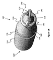
例えば、図1A及び図1Bに示すように、DPIエンジン100は、近位端に、円錐体130の内腔135(図4C)に連結しているか、そうでなければ流体接続している内腔115(図4C)に通じる近位端開口部120を有するマウスピースハウジング110を含み得る。エンジン100の遠位領域において、保持リング140が、円錐体130の遠位部の周囲の少なくとも一部に在る。また、エンジン100の遠位領域に、1つまたは複数の翼状部160及び円錐体130の内腔に通じる第2の空気通路開口部(遠位の第2の開口部)170も在る。エンジン100の遠位の先端に、貫通部材180が在る。DPIエンジンの種々の構成要素は、プラスティックまたは他の望ましいポリマーから構成されてもよく、または、木、金属、セラミックなどの他の剛性材料から構成されてもよい。当業者であれば理解するように、これらの構成要素は、標準的な成型、印刷または他の製造技術から形成されてもよい。
For example, as shown in FIGS. 1A and 1B, the
マウスピースハウジング110は、円錐体130と一体化されて連続装置を形成してもよく、または、円錐体130から着脱可能な別々の部品であってもよい。一つの実施形態では、マウスピースのハウジング110、内腔115及び近位端開口部120は、概ね円筒状である。しかし、ハウジング110、内腔115または近位端開口部120のいずれの形状または寸法に限定がないことは理解されたい。したがって、当業者であれば理解するように、任意の形状が用いられ得る。マウスピース110の近位端は、人間工学的な形状、すなわち対象者の口内で最もうまくなじみ、吸入を介してマウスピース越しに空気を吸い込むような輪郭に成形されることが好ましい。
The
円錐体130は、内腔135に通じる少なくとも2つの開口部を有し、円錐体130の内腔135をマウスピース110の内腔115に接続する近位端開口部及び円錐体130の遠位端近傍の遠位の第2の開口部170である。所望であれば、追加の開口部をハウジング110及び円錐体130の長さ方向に設けてもよい。ある特定の実施形態では、開口部170は、貫通時に開口部170が乾燥粉末収納室内に存在するという条件で、複数の穴または開口部であってもよい。さらに、開口部170は、所望の任意の大きさ及び/または形状を有してもよい。例えば、開口部170は、長円形の開口部、または細長いスロット、または所望の任意の他の形状であってもよい。
The
前述のように、円錐体130は、その長さ方向に、保持リング140から遠位に、1つまたは複数の翼状部160を含む。例えば、一つの実施形態では、円錐体130は単一の翼状部160を有する。別の実施形態では、円錐体130は、図1A及び図1Bに示すように、円錐体130の表面に沿って互いに概ね対向している2つの翼状部160を有する。また、円錐体130は、円錐体130の表面に沿って、互いから径方向に等距離な3つの翼状部160を有してもよい。さらなる実施形態では、円錐体130は、対向する翼状部160の2つ以上のセットを含んでもよく、または、円錐体130の表面に沿って、径方向に等距離な5つ、7つまたは9つの翼状部160を有してもよい。さらなる別の実施形態では、1つまたは複数の翼状部160は、その長さ方向に空間的にセグメント化され、したがって各セグメント空間を空気を流すためのチャネルとして機能させるようにしてもよい。
As mentioned above, the
好ましくは、かつ図1A及び図1Bに示すように、翼状部160は、貫通部材180と一列に並び貫通部材180から近位に延在してもよく、したがって、DPIエンジン100の遠位の先端が乾燥粉末収納室のハウジング部材内に進入した際、翼状部160が乾燥粉末収納室のハウジング部材の開口部を拡開する。一つの実施形態では、少なくとも1つの翼状部160は、貫通部材180の前縁と連続しており、したがって、貫通部材180の前縁(または先端)及び翼状部160が単一構造を形成するようになっている。別の実施形態では、翼状部160は、貫通部材180の前縁と別体ではあるが一列に並んでいる。図1Bに示すように、1つまたは複数の翼状部160のうち少なくとも1つは、1つまたは複数の曲面すなわち湾曲領域162を含み、したがって、保持リング140に接続する翼状部160の近位端の接続点163が、貫通部材180に接続した翼状部160の遠位端の接続点164から最終的にずれるようになっている。翼状部160は、概ね平面的であり、円錐体130から外方に任意の所望の距離だけ延在し得る。さらに、翼状部160は、その長さ方向に、一定のまたは可変の厚さであり得る。翼状部160の厚さは、貫通部材180の厚さ以上であることが好ましい。本明細書に記載されるように、翼状部の曲面形状は、乾燥粉末収納室内に進入した時に、乾燥粉末収納室内に渦気流パターンを生成する働きをし得る。
Preferably, and as shown in FIGS. 1A and 1B, the
乾燥粉末収納室のハウジングを形成するのに用いる材料の種類に応じて、翼状部160は、収納室内に進入した時に収納室の内面に接触するような大きさにしてもよく、または収納室内に進入した時に収納室の内面に接触しないような大きさにしてもよい。したがって、翼状部160の最終的な数、大きさ及び形状に限定はない。
Depending on the type of material used to form the housing of the dry powder storage chamber, the
別の実施形態では、粉末の解凝集をさらに促進しユーザに送達されるエアロゾルの量をさらに増やすために乾燥粉末収納室内に渦を形成する意図をもって、追加の気流入口穴(複数可)から流入する気流を偏向する角度をつけられた形状で、保持リング140より遠位に翼状部160が構成され得る。
In another embodiment, inflow through additional airflow inlet holes (s) with the intention of forming a vortex in the dry powder storage chamber to further promote powder deagglomeration and further increase the amount of aerosol delivered to the user. The
別の実施形態では、翼状部160は、保持リング140より遠位に、鉤状構造、くさびまたは矢尻構造を含んでもよく、したがって、鉤部、くさび部または矢尻部が収納室のハウジングの壁部を完全に通過して進入すると、ハウジングの壁部に、収納室の内部区画に通じる第2の空気入口として機能する拡開開口部が形成される。
In another embodiment, the
円錐体130の貫通部材180は、乾燥粉末収納室のハウジング部材に効果的に穴をあけること及び切断することを促進する概ね矢の形状であり得る。貫通部材180は、遠位の第2の開口部170から遠位に延在することが好ましい。しかし、開口部170は、所望であれば、貫通部材180の全体または一部に組み込まれ得る。さらに、当業者であれば理解するように、貫通部材180は収納室を貫通するのに適切な任意の形状であり得ることを理解されたい。例えば、一つの実施形態では、貫通部材180は少なくとも1つの前縁を含んでもよく、この前縁は収納室に接触し内部に進入する際、乾燥粉末収納室のハウジングを効果的に突き刺し切断する。別の実施形態では、貫通部材180は、収納室のハウジング内に進入する平滑で鋭い先端であり得る。さらに他の実施形態では、遠位の第2の開口部170が遠位の先端に配置され、したがってノズルの形をとり得る。さらに他の実施形態では、貫通部材は用いず、遠位の第2の開口部170が単に乾燥粉末収納室または吸入器の他の粉末貯留区画に進入する。そのような実施形態では、乾燥粉末収納室は、遠位の先端の進入を容易にする弱化された領域またはミシン目を室のハウジングに含んでもよく、または収納室は、吸入器の別体の部品によって予め切断され得る。さらに、遠位の先端は単に、スリットバルブを通して吸入器内の別体の乾燥粉末貯留区画内に進入し得る。したがって、本明細書で企図されるように、遠位の第2の開口部170は所望の任意の大きさまたは形状であってよく、一般に貫通部材の任意的な存在及び/または形状に左右されるであろう。例えば、遠位の第2の開口部は、円錐体表面の遠位領域に沿う1つまたは複数の横方向スロットであってもよく、または、円錐体の遠位の先端の単一のボアホールであってもよい。遠位の第2の開口部170の数、大きさ及び形状に限定はないことを理解されたい。
The penetrating
ハウジング110は、マウスピースのハウジングの壁部に、内腔115に通じて開口する開口部すなわち穴150も含んでもよく、それにより、空気が外部環境から内腔115内に流れる通路が提供される。したがって、一つの実施形態では、開口部150は気流追跡経路として機能することができ、したがって、浮遊粉末粒子の速度を速めることができ、乾燥粉末収納室から内腔115内に吸い込まれた任意の浮遊粉末粒子がマウスピース内にかつ/またはユーザの口内に沈降する代わりに、それを肺の奥深くまで送達することができるようになる。開口部150は、バルブ、ユーザの指または気流に対して穴150をふさぐかつ開放する任意の他の機構を介して、穴150を開閉することによって実現し得る。
The
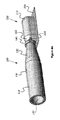
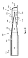
図2A及び図2Bは、本明細書で記載したDPIエンジンとともに用いるのに適した様々な種類の乾燥粉末収納室を図示する。例えば、図2Aに示すように、収納室は、通常ヒプロメロース(HPMC)から製造されるカプセルなどのカプセル200の形をとり得る。図2Bでは、収納室は、通常ポリ塩化ビニル(PVC)から製造されるブリスターパックなどのブリスターパック210の形をとり得る。ブリスターパック210は、一般に、平坦面214に固定された密封室構成要素212を含み得る。当業者に理解される任意の種類の密封室は、以下の場合に限り、DPIエンジンとともに用い得ることを理解されたい。それは、DPIエンジンの遠位の先端がハウジング内の密封室に接触し貫通し得るような、吸入器内での密封室の位置合わせができるように、吸入器のハウジングが適切に設計されている場合である。乾燥粉末収納室に用いられる材料は、DPIエンジン100の貫通部材180及び1つまたは複数の翼状部160によって切断または突き刺された時に気流入口穴が形成され維持されるのに残留塑性変形が十分であるような弾塑性挙動を示すことが好ましい。
2A and 2B illustrate various types of dry powder storage chambers suitable for use with the DPI engines described herein. For example, as shown in FIG. 2A, the storage chamber can take the form of a
図3Aは、HPMCカプセル材料の典型的な弾塑性の応力・ひずみ曲線を示し、図3Bは、PVCブリスター部材の典型的な弾塑性の応力・ひずみ曲線を示す。これらの曲線では、典型的なカプセルの材料及びブリスターパックの材料は弾塑性挙動を示すことが把握できる。ひずみ値0.03よりも低くたわんだ時、応力及びひずみは直線またはほぼ完全な弾性で近似することができる。この弾性域で、たわんだ材料は、応力が除外されると元の形状に戻るであろう。しかし、ひずみが0.05を超えると、塑性変形により、材料は元の形状に回復することを妨げられ得る。本明細書で記載した翼状部を有する実施形態は、容器の材料の塑性変形を利用するものである。塑性変形は、湾曲領域162を有する翼状部160によって開口した第2の穴220が、弾性回復により穴周囲が開口したままで閉じないことを確実にする。
FIG. 3A shows a typical elasto-plastic stress / strain curve of HPMC capsule material, and FIG. 3B shows a typical elasto-plastic stress / strain curve of a PVC blister member. From these curves, it can be seen that typical capsule and blister pack materials exhibit elasto-plastic behavior. When flexed below a strain value of 0.03, the stress and strain can be approximated by a straight line or near perfect elasticity. In this elastic region, the flexed material will return to its original shape when the stress is removed. However, if the strain exceeds 0.05, plastic deformation can prevent the material from recovering to its original shape. The embodiment having a wing-shaped portion described herein utilizes plastic deformation of the material of the container. The plastic deformation ensures that the
ここで図4A〜図4C及び図5を参照して、ブリスターパックの収納室(図4A〜図4C)またはカプセル(図5)に係合した状態のDPIエンジンを図示する。以下の例示で、一般に収納室の細長い端部領域で収納室と係合しているDPIエンジンを示しているが、DPIエンジンによる収納室の内部区画への貫通及びアクセスが行われる実際の場所に関して限定はされない。 Here, with reference to FIGS. 4A-4C and 5, a DPI engine in a state of being engaged with a blister pack storage chamber (FIGS. 4A-4C) or a capsule (FIG. 5) is illustrated. The following illustration generally shows a DPI engine engaged with a storage chamber in the elongated end region of the storage chamber, but with respect to the actual location where the DPI engine penetrates and accesses the internal compartment of the storage chamber. There is no limitation.
図4A〜図4Cに示すように、貫通部材180は、収納室212のハウジングの壁部を切断または突き刺すようなサイズ及び形状にされている。ある特定の実施形態では、平坦面214は、エンジン100の貫通部材180が係合したときに収納室212が望まないずれや回転を起こさないように、吸入器内で収納室212を安定化させ、かつ/または固定する機能を持ち得る。貫通部材180は、室212のハウジングの壁部を切断または突き刺した後に、室212のハウジングの壁部が保持リング140に当接するまで室212の内部区画216内に進入し、それによって、1つまたは複数の翼状部160も少なくとも部分的に進入する開口部が生成される。図4Bにより詳しく示すように、1つまたは複数の翼状部160が少なくとも部分的に収納室212へと開口部を通過すると、翼状部160の曲面領域162は、室212のハウジングの壁部に、翼状部の接続点163に隣接した拡開開口部220を生成する。したがって、貫通部材180によって収納室のハウジングに生成された初期開口部を通って翼状部160を少なくとも部分的に進入させることによって、拡開された無抑制の開口部220を、円錐体130に軸回転を加えることなく形成することができる。示すように、拡開された無抑制の開口部220は、室212の内部区画216に通じる第2の空気入口として機能し得る。
As shown in FIGS. 4A-4C, the penetrating
使用時にかつ図6及び図7を参照して、対象者はまず、DPIエンジン100の遠位の先端を乾燥粉末収納室210または212に係合させ、室のハウジングを貫通させ、したがって、DPIエンジンの円錐体の先端が、保持リング140が室のハウジングの壁部に当接するまで室の内部区画内に進入するようにする。次に、対象者は、マウスピース110の開口部120を通して吸入してもよく、それにより、マウスピース110の内腔115内にかつ円錐体130の内腔135内に陰圧を発生させる。この陰圧は、外部環境から(例えば、乾燥粉末収納室が配置された内部室から)、室212の第2の開口部220を通って、乾燥粉末が存在する内部区画216内に流入空気を引き込み、その後、内部区画216の流入空気は、遠位の第2の開口部170を通って円錐体130の内腔135に入り込む。図7に示すように、翼状部160により、第2の気流経路からの気流は渦気流パターン230及び渦気流パターン240を形成して、内部室216内の粉末を遊離させ、流動化させ、エアロゾル化させて、遠位の第2の開口部170を通って流出させ、内腔135及び内腔115を通るように方向付け、近位開口部120を通ってDPIエンジン100を出て対象者の肺に向かう。例えば、矢印230に対応する気流は、室212の第2の開口部220で入ってくる気流を示し、ここで翼状部160の形状及び/または位置は回転流を誘導する。次いで、回転流は、内部区画216内の室のハウジングの内面に沿ってずっと続いて、乾燥粉末を遊離させ、流動化させ、エアロゾル化させる。次いで、同伴空気とともに、乾燥粉末は、矢印240に対応する気流を介して遠位の第2の開口部170を通って円錐体130の内腔135内に取り入れられる。このように、エアロゾル化された粉末は、実質的に内腔135及び内腔115を通して方向付けられ、近位開口部120を通ってDPIエンジン100を出て対象者の肺に向かう。
Referring to FIGS. 6 and 7 and at the time of use, the subject is first engaged the distal of the previous end of the
したがって、密封室から対象者の気道に乾燥粉末を送達する方法が提供される。この方法は、乾燥粉末を含有する収納室のハウジングを中空装置の遠位端で貫通するステップであって、該装置が少なくとも1つの近位開口部、少なくとも1つの遠位開口部及び該中空装置の遠位端の近傍に少なくとも1つの翼状部を包含しているステップと、少なくとも1つの遠位開口部のうち少なくとも1つを収納室の内部に進入させるステップと、少なくとも1つの翼状部の少なくとも一部を乾燥粉末を含む収納室の内部に進入させて、収納室のハウジングに少なくとも1つの拡開開口部を生成するステップと、吸入を介して中空装置の近位開口部から対象者の吸い込んだ息によって、中空装置内に陰圧を発生させるステップと、気流を生成するステップであって、気流が、少なくとも1つの拡開開口部を通って収納室に入り、収納室内の乾燥粉末の少なくとも一部を気流中に舞い上げ、収納室内に進入した装置の少なくとも1つの遠位開口部を通過し、したがって、気流中の乾燥粉末を、行われた吸入を介して対象者の気道内に運ぶために装置の中空領域を通って移動させる、ステップとを含む。 Therefore, a method of delivering the dry powder from the sealed chamber to the subject's airways is provided. This method is a step of penetrating the housing of the storage chamber containing the dry powder at the distal end of the hollow device, wherein the device has at least one proximal opening, at least one distal opening and the hollow device. A step that includes at least one wing-shaped portion in the vicinity of the distal end of the wing, a step that allows at least one of the at least one distal opening to enter the interior of the storage chamber, and at least one wing-shaped portion. Inhalation of the subject through the proximal opening of the hollow device via inhalation and the step of allowing a portion to enter the interior of the storage chamber containing the dry powder to create at least one widening opening in the housing of the storage chamber. A step of generating negative pressure in the hollow device by breathing and a step of generating an air flow, in which the air flow enters the storage chamber through at least one widening opening and at least the dry powder in the storage chamber. Part of it is lifted into the air stream, passes through at least one distal opening of the device that has entered the containment chamber, and thus carries the dry powder in the air flow into the subject's airway via inhalation performed. Includes steps and movements for moving through the hollow area of the device.
本明細書で記載され企図されるDPIエンジンによって乾燥粉末収納室内での乱流が著しく増加することが示されるので、DPIエンジンの使用により、既存の装置及びシステムに比べて大幅な予想以上の改良が示される。いかなる特定の理論にも限定されることなしに、この大幅な予想以上の改良は、一つには、翼状部をDPIエンジンの遠位領域近傍に配置したことによるものである。翼状部は2つの機能をもたらす。第1に、翼状部は、室に入ってきた空気の流れを旋回パターンとして方向付けて、乾燥粉末収納室の内面の粉末を掃き集め、円錐体の先端に入っていく気流を形成し、それにより、患者の口に向かう空気の流れに引き込む。第2に、翼状部が室のハウジングの壁部を通過する際、翼状部によって、乾燥粉末室に通じる開口部が拡張または拡開される。空気を同伴させる目的で、対称的かつ均一な開口部を生成することが好ましい。したがって、1つまたは複数の翼状部により、著しくより多くの粉末が、DPIエンジンの遠位の先端開口部からより離れたところで舞い上げられ、さらに、乾燥粉末区画の内部壁に沿って渦が生成されて、内部室面での掃き集めを増やして拾い上げられる粉末を増加させる。
Since the DPI engine described and contemplated herein has been shown to significantly increase turbulence in the dry powder storage chamber, the use of the DPI engine is a significant over-expected improvement over existing equipment and systems. Is shown. Without being limited to any particular theory, this significant over-expected improvement is in part due to the placement of the wing near the distal region of the DPI engine. The winged part provides two functions. First, the wing-shaped section directs the flow of air entering the chamber as a swirling pattern, sweeping up the powder on the inner surface of the dry powder storage chamber and forming an airflow entering the tip of the cone. Pulls into the air flow towards the patient's mouth. Second, as the wing passes through the wall of the chamber housing, the wing expands or opens the opening leading to the dry powder chamber. It is preferable to create symmetrical and uniform openings for the purpose of entraining air. Thus, one or more wings, many powder than significantly, to rise up at the further from the distal of the previous end opening of the DPI engine, further, the vortex along the interior wall of the dry powder compartment Increases the amount of powder that is produced and picked up on the inner chamber surface.
本明細書で引用されるありとあらゆる特許、特許出願、および刊行物は、参照によりそれらの全体が本明細書に組み込まれる。本発明は、具体的な実施形態を参照して開示されたが、当業者によって、本発明の真の趣旨及び範囲から逸脱することなく、本発明の他の実施形態及び変形が考案されてもよいことは明らかである。添付の特許請求の範囲は、このような全ての実施形態及び均等の変形例を包含するように解釈されることが意図される。 All patents, patent applications, and publications cited herein are incorporated herein by reference in their entirety. The present invention has been disclosed with reference to specific embodiments, but other embodiments and modifications of the invention may be devised by those skilled in the art without departing from the true spirit and scope of the invention. It's clear that it's good. The appended claims are intended to be construed to include all such embodiments and equivalent variations.
Claims (16)
外面を定める壁部、近位端、遠位端及びそれらの間に長さを有するハウジングであって、実質的に前記ハウジングの長さ方向に内腔を形成する前記ハウジングと、
前記内腔に通じる少なくとも1つの近位端開口部、前記内腔に通じる遠位の第2の開口部、及び前記壁部を通じて前記内腔にまで及ぶ穴であって前記近位端開口部と前記遠位の第2の開口部との間に配置された前記穴と、
前記ハウジングの外面から延在し、前記穴から遠位に配置された少なくとも1つの翼状構造と、
前記装置のハウジングの前記遠位端の貫通部材を備え、前記貫通部材が少なくとも1つの前縁を備え、前記少なくとも1つの翼状構造が前記少なくとも1つの前縁と一列に並んでいる、前記装置。 A device that accesses dry powder in a sealed chamber
A housing having a length between a wall portion, a proximal end, a distal end, and the outer surface, which substantially forms a lumen in the length direction of the housing.
At least one proximal end opening leading to the lumen, a second distal opening leading to the lumen, and a hole extending through the wall to the lumen with the proximal end opening. With the hole disposed between the distal second opening,
With at least one winged structure extending from the outer surface of the housing and located distal to the hole .
A through member of the distal end of the housing of the device, wherein the penetrating member is provided with at least one front edge, said that lined up at least one wing-like structure is at least one leading edge and one row, said device ..
前記乾燥粉末吸入器内に配置された密封容器内の乾燥粉末にアクセスする乾燥粉末吸入器エンジンを備え、該乾燥粉末吸入器エンジンは、
本体及び実質的に前記乾燥粉末吸入器エンジンの前記本体の長さ方向の内腔、前記本体の近位端における前記内腔内への近位端開口部、前記本体の遠位の先端における前記内腔内への少なくとも1つの遠位の第2の開口部、及び前記乾燥粉末吸入器エンジンの前記本体の遠位面から延在する少なくとも1つの翼状部と、
マウスピースと、
前記乾燥粉末吸入器エンジンの前記遠位の先端の貫通部材を備え、前記貫通部材が少なくとも1つの前縁を備え、前記少なくとも1つの翼状部が前記少なくとも1つの前縁と一列に並んでおり、
前記マウスピースが前記乾燥粉末吸入器エンジンの前記近位端開口部に接続され、
前記乾燥粉末吸入器エンジンの前記遠位の先端の前記少なくとも一部が前記吸入器内に配置されている、前記乾燥粉末吸入器。 A dry powder inhaler
Comprising a dry powder inhaler engine to access the dry powder sealed container disposed in said dry powder inhaler, said dry powder inhaler engine,
Body and substantially the dry powder inhaler the main body in the length direction of the lumen of the engine, the proximal end opening into the lumen at the proximal end of said body, said at the distal tip of the body the second opening of the at least one distal to the lumen, and at least one wing portion extending from a distal surface of the body of the dry powder inhaler engine,
And the mouthpiece,
A penetrating member at the distal tip of the dry powder inhaler engine, the penetrating member having at least one leading edge, and at least one winged portion aligned with the at least one leading edge .
The mouthpiece is connected to the proximal end opening of the dry powder inhaler engine.
The dry powder inhaler The dry powder inhaler, wherein at least a portion of the distal tip of the dry powder inhaler engine is located within the inhaler.
請求項1の前記装置の前記遠位端を用いて乾燥粉末を含有する収納室を貫通することと、
前記遠位の第2の開口部を前記収納室の内部に進入させることと、
前記少なくとも1つの翼状構造の少なくとも一部を乾燥粉末を含む前記収納室の内部に進入させて、前記収納室のハウジングに少なくとも1つの拡開開口部を形成することとを備える方法。 A way to access the dry powder in a sealed container,
Using the distal end of the device of claim 1 to penetrate a storage chamber containing a dry powder.
To allow the distal second opening to enter the interior of the storage chamber,
How and a said at least a portion of at least one wing-like structure is advanced into the interior of the housing chamber containing the dry powder to form at least one flared opening in the housing of the storage chamber.
Applications Claiming Priority (3)
| Application Number | Priority Date | Filing Date | Title |
|---|---|---|---|
| US201562147808P | 2015-04-15 | 2015-04-15 | |
| US62/147,808 | 2015-04-15 | ||
| PCT/US2016/027252 WO2016168274A1 (en) | 2015-04-15 | 2016-04-13 | Dry powder inhaler and method of use |
Publications (3)
| Publication Number | Publication Date |
|---|---|
| JP2018513765A JP2018513765A (en) | 2018-05-31 |
| JP2018513765A5 JP2018513765A5 (en) | 2021-04-01 |
| JP6926063B2 true JP6926063B2 (en) | 2021-08-25 |
Family
ID=57126829
Family Applications (1)
| Application Number | Title | Priority Date | Filing Date |
|---|---|---|---|
| JP2018505571A Active JP6926063B2 (en) | 2015-04-15 | 2016-04-13 | Dry powder inhaler and how to use |
Country Status (10)
| Country | Link |
|---|---|
| US (1) | US11090448B2 (en) |
| EP (1) | EP3283151B1 (en) |
| JP (1) | JP6926063B2 (en) |
| KR (1) | KR102568622B1 (en) |
| CN (1) | CN107635612B (en) |
| AU (1) | AU2016247914B2 (en) |
| BR (1) | BR112017022182A2 (en) |
| CA (1) | CA2983026A1 (en) |
| RU (1) | RU2715687C2 (en) |
| WO (1) | WO2016168274A1 (en) |
Families Citing this family (15)
| Publication number | Priority date | Publication date | Assignee | Title |
|---|---|---|---|---|
| US10244793B2 (en) | 2005-07-19 | 2019-04-02 | Juul Labs, Inc. | Devices for vaporization of a substance |
| USD842536S1 (en) | 2016-07-28 | 2019-03-05 | Juul Labs, Inc. | Vaporizer cartridge |
| US20160366947A1 (en) | 2013-12-23 | 2016-12-22 | James Monsees | Vaporizer apparatus |
| US10159282B2 (en) | 2013-12-23 | 2018-12-25 | Juul Labs, Inc. | Cartridge for use with a vaporizer device |
| US10058129B2 (en) | 2013-12-23 | 2018-08-28 | Juul Labs, Inc. | Vaporization device systems and methods |
| KR102256889B1 (en) | 2013-12-23 | 2021-05-31 | 쥴 랩스, 인크. | Vaporization device systems and methods |
| US10076139B2 (en) | 2013-12-23 | 2018-09-18 | Juul Labs, Inc. | Vaporizer apparatus |
| CA160775S (en) | 2014-08-11 | 2015-09-29 | Ploom Inc | Electronic vaporization device with cartridge |
| CN107635612B (en) * | 2015-04-15 | 2021-09-14 | 菲利普莫里斯生产公司 | Dry powder inhaler and method of use |
| EP3419443A4 (en) | 2016-02-11 | 2019-11-20 | Juul Labs, Inc. | Securely attaching cartridges for vaporizer devices |
| USD849996S1 (en) | 2016-06-16 | 2019-05-28 | Pax Labs, Inc. | Vaporizer cartridge |
| USD836541S1 (en) | 2016-06-23 | 2018-12-25 | Pax Labs, Inc. | Charging device |
| USD851830S1 (en) | 2016-06-23 | 2019-06-18 | Pax Labs, Inc. | Combined vaporizer tamp and pick tool |
| USD887632S1 (en) | 2017-09-14 | 2020-06-16 | Pax Labs, Inc. | Vaporizer cartridge |
| WO2023186758A1 (en) * | 2022-03-28 | 2023-10-05 | Astrazeneca Ab | Dry powder formulation inhaler and capsule |
Family Cites Families (70)
| Publication number | Priority date | Publication date | Assignee | Title |
|---|---|---|---|---|
| US5441060A (en) * | 1993-02-08 | 1995-08-15 | Duke University | Dry powder delivery system |
| DE19757207A1 (en) * | 1997-12-22 | 1999-06-24 | Alfred Von Schuckmann | Blister pack unit useful for removing powder from cavities in blister packs |
| GB9810126D0 (en) * | 1998-05-13 | 1998-07-08 | Glaxo Group Ltd | |
| WO1999056807A1 (en) * | 1998-05-04 | 1999-11-11 | Glaxo Group Limited | Unit dose inhaler apparatus and method of delivery using same |
| US6257233B1 (en) * | 1998-06-04 | 2001-07-10 | Inhale Therapeutic Systems | Dry powder dispersing apparatus and methods for their use |
| US6234169B1 (en) * | 1998-08-14 | 2001-05-22 | Arthur Slutsky | Inhaler |
| SE9904705D0 (en) * | 1999-12-21 | 1999-12-21 | Astra Ab | An inhalation device |
| FI20000810A0 (en) * | 2000-04-06 | 2000-04-06 | Orion Yhtymae Oyj | The powder inhaler |
| US6948494B1 (en) * | 2000-05-10 | 2005-09-27 | Innovative Devices, Llc. | Medicament container with same side airflow inlet and outlet and method of use |
| JP3974748B2 (en) * | 2000-11-29 | 2007-09-12 | 株式会社日立製作所 | Powder suction tool |
| US7415982B1 (en) * | 2001-02-15 | 2008-08-26 | Sheridan Timothy B | Smokeless pipe |
| SE0101825D0 (en) * | 2001-05-22 | 2001-05-22 | Astrazeneca Ab | An inhalation device |
| JP2006511257A (en) * | 2002-10-30 | 2006-04-06 | グラクソ グループ リミテッド | Tubular nozzle for use in a system for drug delivery |
| AU2003293361A1 (en) * | 2002-12-18 | 2004-07-29 | Glaxo Group Limited | Drug delivery system with vented mouthpiece |
| US8869794B1 (en) * | 2003-04-09 | 2014-10-28 | Novartis Pharma Ag | Aerosolization apparatus with capsule puncturing member |
| JP2006522634A (en) * | 2003-04-14 | 2006-10-05 | ベクトゥラ・リミテッド | Device and pharmaceutical composition for improving administration efficiency |
| GB2405798A (en) * | 2003-09-15 | 2005-03-16 | Vectura Ltd | Dry powder inhaler with primary and secondary piercing elements and a medicament pack for use with an inhalation device. |
| GB0324897D0 (en) * | 2003-10-24 | 2003-11-26 | Glaxo Group Ltd | Composition |
| GB0324918D0 (en) * | 2003-10-24 | 2003-11-26 | Glaxo Group Ltd | Composition |
| WO2005041848A2 (en) * | 2003-10-27 | 2005-05-12 | Oriel Therapeutics, Inc. | Dry powder drug containment system packages with tabs, inhalers and associated methods |
| US20050121025A1 (en) * | 2003-12-04 | 2005-06-09 | Gamard Stephan C.F. | Portable gas operating inhaler |
| WO2005065756A2 (en) * | 2003-12-30 | 2005-07-21 | Oriel Therapeutics, Inc. | Dry powder nebulizers and associated methods of dispensing dry powders |
| US8210171B2 (en) * | 2004-09-13 | 2012-07-03 | Oriel Therapeutics, Inc. | Tubular dry powder drug containment systems, associated inhalers and methods |
| FR2877925B1 (en) * | 2004-11-16 | 2008-09-19 | Valois Sas | DEVICE FOR DISPENSING FLUID PRODUCT. |
| GB0507711D0 (en) * | 2005-04-15 | 2005-05-25 | Vectura Group Plc | Improved blister piercing |
| US20080251072A1 (en) * | 2005-07-13 | 2008-10-16 | Amar Lulla | Inhaler Device |
| GB0520794D0 (en) * | 2005-10-12 | 2005-11-23 | Innovata Biomed Ltd | Inhaler |
| JP4458364B2 (en) * | 2005-10-18 | 2010-04-28 | キヤノン株式会社 | Liquid ejection device and liquid ejection cartridge used in the ejection device |
| US8360057B2 (en) * | 2006-03-10 | 2013-01-29 | Dose One, Llc | Medication inhaler for dispensing multiple capsules |
| US20080210228A1 (en) * | 2007-03-02 | 2008-09-04 | Corbco, Inc. | Monodose nasal sprayer |
| WO2009004465A1 (en) * | 2007-07-02 | 2009-01-08 | Pfizer Limited | Dry powder inhaler and inhaling system comprising such dry powder inhaler |
| FR2918352B1 (en) * | 2007-07-03 | 2009-10-09 | Valois Sas | TANK OPENING DEVICE FOR FLUID PRODUCT DISPENSING DEVICE |
| DE102007056263A1 (en) | 2007-11-22 | 2009-05-28 | Siegfried Generics International Ag | Dosing device for inhaling a powdery substance |
| KR101529354B1 (en) * | 2007-12-05 | 2015-06-16 | 노파르티스 아게 | Receptacle for an aerosolizable pharmaceutical formulation |
| JP2009213618A (en) * | 2008-03-10 | 2009-09-24 | Canon Inc | Non-discharge liquid cartridge and liquid agent discharger |
| WO2009117112A2 (en) * | 2008-03-21 | 2009-09-24 | Novartis Ag | Powder dispersion apparatus, method of making and using the apparatus, components that can be used on the apparatus and other devices, and various active agents |
| CN104689432B (en) * | 2008-06-13 | 2018-07-06 | 曼金德公司 | Diskus and the system for drug conveying |
| US8485180B2 (en) * | 2008-06-13 | 2013-07-16 | Mannkind Corporation | Dry powder drug delivery system |
| AT507631B1 (en) * | 2008-11-26 | 2012-05-15 | Haas Rouven Mag | DEVICE FOR INTAKING POWDER OR GRANULATE MATERIAL AND CAPSULE THEREFOR |
| CA2791847C (en) * | 2009-03-04 | 2017-05-02 | Mannkind Corporation | An improved dry powder drug delivery system |
| US9492625B2 (en) * | 2009-11-12 | 2016-11-15 | Stc.Unm | Dry powder inhaler with flutter dispersion member |
| WO2011112531A2 (en) * | 2010-03-08 | 2011-09-15 | Stc. Unm | Dry powder nebulizer |
| GB2492035B (en) * | 2010-04-23 | 2014-03-05 | Cambridge Consultants | Dry powder inhaler assembly and containers |
| PT105065B (en) * | 2010-04-26 | 2012-07-31 | Hovione Farmaciencia S A | A SIMPLE INHALER OF CAPSULES |
| FR2962343B1 (en) * | 2010-07-07 | 2012-08-03 | Valois Sas | DRY POWDER INHALER. |
| GB201018796D0 (en) * | 2010-11-08 | 2010-12-22 | British American Tobacco Co | Aerosol generator |
| DK2646094T3 (en) * | 2010-11-29 | 2015-07-06 | Sanofi Aventis Deutschland | MEDICINE MODULE FOR AN INHALATOR |
| US8561609B2 (en) * | 2010-12-07 | 2013-10-22 | Respira Therapeutics, Inc. | Dry powder inhaler |
| US20120174914A1 (en) * | 2011-01-08 | 2012-07-12 | Nasser Pirshafiey | Electronic vapor inhaling device |
| CN103687503A (en) * | 2011-04-12 | 2014-03-26 | 罗伯特·列维兹 | Battery connector for electronic cigarette with side air intake |
| CA2835208C (en) * | 2011-05-09 | 2019-08-20 | Impel Neuropharma, Inc. | Nozzles for nasal drug delivery |
| US20140224248A1 (en) * | 2011-05-11 | 2014-08-14 | Aerodesigns, Inc. | Aerosol delivery apparatus |
| WO2013036881A2 (en) * | 2011-09-07 | 2013-03-14 | Syphase, Llc | Dry powder inhalation device |
| US10105500B2 (en) * | 2012-05-09 | 2018-10-23 | Virginia Commonwealth University | Dry powder inhaler (DPI) designs for producing aerosols with high fine particle fractions |
| EP3248642B1 (en) * | 2012-06-28 | 2020-04-08 | The Government of The United States of America as represented by The Secretary of The Department of Health and Human Services | Nasal dry powder delivery system for vaccines and other treatment agents |
| WO2014046993A1 (en) * | 2012-09-24 | 2014-03-27 | Aerodesigns, Inc. | Flow diverter for a mouthpiece of a particule delivery device |
| WO2014089174A2 (en) * | 2012-12-06 | 2014-06-12 | Aerodesigns, Inc. | Aerosol dispenser with edible cartridge |
| GB201301192D0 (en) * | 2013-01-23 | 2013-03-06 | Vectura Delivery Devices Ltd | A blister piercing element for a dry powder inhaler |
| EP2964297B1 (en) * | 2013-03-08 | 2020-05-06 | Interquim, S.A. | Inhaler |
| WO2014150826A1 (en) * | 2013-03-15 | 2014-09-25 | Aerodesigns, Inc. | Aerosol dispenser with edible cartridge |
| CN105072936B (en) * | 2013-03-15 | 2018-09-25 | 菲利普莫里斯生产公司 | Aerosol with piercing element generates system |
| US20160366947A1 (en) * | 2013-12-23 | 2016-12-22 | James Monsees | Vaporizer apparatus |
| KR102256889B1 (en) * | 2013-12-23 | 2021-05-31 | 쥴 랩스, 인크. | Vaporization device systems and methods |
| CA2943746C (en) * | 2014-04-28 | 2023-08-15 | Philip Morris Products S.A. | Flavoured nicotine powder inhaler |
| KR102428026B1 (en) * | 2014-04-28 | 2022-08-03 | 필립모리스 프로덕츠 에스.에이. | Nicotine powder inhaler |
| CN107635612B (en) * | 2015-04-15 | 2021-09-14 | 菲利普莫里斯生产公司 | Dry powder inhaler and method of use |
| BR112017022186A2 (en) * | 2015-04-15 | 2018-07-03 | Stenzler Alex | dry powder inhaler, and method for providing an amount of a dry powder nicotine formulation in a varying number of inhalations |
| EP3291867B1 (en) * | 2015-04-15 | 2021-06-09 | Philip Morris Products S.A. | Flavoring element for an inhalation device |
| EP3283150B1 (en) * | 2015-04-15 | 2021-09-29 | Philip Morris Products S.A. | Dual resistance dry powder inhaler |
| WO2017079397A1 (en) * | 2015-11-05 | 2017-05-11 | Otitopic Inc. | Dry powder inhalation device |
-
2016
- 2016-04-13 CN CN201680032932.1A patent/CN107635612B/en active Active
- 2016-04-13 WO PCT/US2016/027252 patent/WO2016168274A1/en active Application Filing
- 2016-04-13 KR KR1020177032808A patent/KR102568622B1/en active IP Right Grant
- 2016-04-13 US US15/566,412 patent/US11090448B2/en active Active
- 2016-04-13 CA CA2983026A patent/CA2983026A1/en not_active Abandoned
- 2016-04-13 EP EP16780607.4A patent/EP3283151B1/en active Active
- 2016-04-13 RU RU2017136808A patent/RU2715687C2/en active
- 2016-04-13 BR BR112017022182-9A patent/BR112017022182A2/en not_active IP Right Cessation
- 2016-04-13 JP JP2018505571A patent/JP6926063B2/en active Active
- 2016-04-13 AU AU2016247914A patent/AU2016247914B2/en not_active Ceased
Also Published As
| Publication number | Publication date |
|---|---|
| EP3283151A4 (en) | 2018-12-26 |
| AU2016247914B2 (en) | 2020-06-18 |
| KR20170142178A (en) | 2017-12-27 |
| RU2017136808A (en) | 2019-05-15 |
| KR102568622B1 (en) | 2023-08-22 |
| BR112017022182A2 (en) | 2018-07-03 |
| CN107635612A (en) | 2018-01-26 |
| EP3283151B1 (en) | 2022-07-20 |
| US11090448B2 (en) | 2021-08-17 |
| CA2983026A1 (en) | 2016-10-20 |
| AU2016247914A1 (en) | 2017-11-16 |
| RU2017136808A3 (en) | 2019-08-28 |
| CN107635612B (en) | 2021-09-14 |
| WO2016168274A1 (en) | 2016-10-20 |
| JP2018513765A (en) | 2018-05-31 |
| US20180140790A1 (en) | 2018-05-24 |
| RU2715687C2 (en) | 2020-03-02 |
| EP3283151A1 (en) | 2018-02-21 |
Similar Documents
| Publication | Publication Date | Title |
|---|---|---|
| JP6926063B2 (en) | Dry powder inhaler and how to use | |
| JP2018513765A5 (en) | ||
| JP4166950B2 (en) | Inhaler | |
| EP3393560B1 (en) | Nicotine powder delivery system | |
| ES2599302T3 (en) | Inhaler | |
| EP2866867B1 (en) | Nasal dry powder delivery system for vaccines and other treatment agents | |
| JP3790423B2 (en) | Dry powder drug inhaler with inhalation activated flow splitting means to trigger drug delivery | |
| US20080251072A1 (en) | Inhaler Device | |
| CN110730674B (en) | Dry powder inhaler and spacer for a dry powder inhaler | |
| US20180289904A1 (en) | Devices and methods for puncturing a capsule to release a powdered medicament therefrom | |
| US11033692B2 (en) | Flavoring element for an inhalation device | |
| BR112018075142B1 (en) | ARTICLE FOR USE IN A NICOTINE INHALER AND INHALER | |
| EP3344316A1 (en) | Dry powder inhaler | |
| JP2023552840A (en) | Inhaler system with offset perforation |
Legal Events
| Date | Code | Title | Description |
|---|---|---|---|
| A711 | Notification of change in applicant |
Free format text: JAPANESE INTERMEDIATE CODE: A711 Effective date: 20180808 |
|
| A621 | Written request for application examination |
Free format text: JAPANESE INTERMEDIATE CODE: A621 Effective date: 20190408 |
|
| A977 | Report on retrieval |
Free format text: JAPANESE INTERMEDIATE CODE: A971007 Effective date: 20200213 |
|
| A131 | Notification of reasons for refusal |
Free format text: JAPANESE INTERMEDIATE CODE: A131 Effective date: 20200330 |
|
| A521 | Request for written amendment filed |
Free format text: JAPANESE INTERMEDIATE CODE: A523 Effective date: 20200622 |
|
| A131 | Notification of reasons for refusal |
Free format text: JAPANESE INTERMEDIATE CODE: A131 Effective date: 20201203 |
|
| A524 | Written submission of copy of amendment under article 19 pct |
Free format text: JAPANESE INTERMEDIATE CODE: A524 Effective date: 20210216 |
|
| TRDD | Decision of grant or rejection written | ||
| A01 | Written decision to grant a patent or to grant a registration (utility model) |
Free format text: JAPANESE INTERMEDIATE CODE: A01 Effective date: 20210705 |
|
| A61 | First payment of annual fees (during grant procedure) |
Free format text: JAPANESE INTERMEDIATE CODE: A61 Effective date: 20210804 |
|
| R150 | Certificate of patent or registration of utility model |
Ref document number: 6926063 Country of ref document: JP Free format text: JAPANESE INTERMEDIATE CODE: R150 |