JP6922626B2 - Support structure of transfer device - Google Patents
Support structure of transfer device Download PDFInfo
- Publication number
- JP6922626B2 JP6922626B2 JP2017191302A JP2017191302A JP6922626B2 JP 6922626 B2 JP6922626 B2 JP 6922626B2 JP 2017191302 A JP2017191302 A JP 2017191302A JP 2017191302 A JP2017191302 A JP 2017191302A JP 6922626 B2 JP6922626 B2 JP 6922626B2
- Authority
- JP
- Japan
- Prior art keywords
- cross member
- transfer device
- side member
- vehicle
- bracket
- Prior art date
- Legal status (The legal status is an assumption and is not a legal conclusion. Google has not performed a legal analysis and makes no representation as to the accuracy of the status listed.)
- Active
Links
Images


Description
本発明は、車両に搭載されるトランスファ装置の支持構造に関する。 The present invention relates to a support structure for a transfer device mounted on a vehicle.
車両には、変速機の動力を前後輪に分配するためのトランスファ装置が設けられており、トランスファ装置は、車体に支持されている。従来のトランスファ装置の支持構造としては、特許文献1に記載されたものが知られている。 The vehicle is provided with a transfer device for distributing the power of the transmission to the front and rear wheels, and the transfer device is supported by the vehicle body. As a support structure of a conventional transfer device, the one described in Patent Document 1 is known.
特許文献1に記載されるトランスファ装置の支持構造は、車両の前後方向に延びる一対のサイドフレームをクロスメンバにより連結している。クロスメンバは、トランスファ装置の本体部の重心位置を挟んで前後に並ぶ2本のクロスメンバ部を有し、クロスメンバ部によってトランスファ装置を支持している。 In the support structure of the transfer device described in Patent Document 1, a pair of side frames extending in the front-rear direction of the vehicle are connected by a cross member. The cross member has two cross member portions arranged in the front-rear direction with the center of gravity of the main body portion of the transfer device in between, and the transfer device is supported by the cross member portion.
このような従来のトランスファ装置の支持構造にあっては、2本のクロスメンバ部によってトランスファ装置を支持しているだけであるので、トランスファ装置の振動がクロスメンバを介してサイドフレームに伝達され易い。これにより、車両の乗り心地が悪化するおそれがある。 In such a conventional transfer device support structure, since the transfer device is only supported by two cross member portions, the vibration of the transfer device is easily transmitted to the side frame via the cross member. .. As a result, the ride quality of the vehicle may deteriorate.
本発明は、上記のような問題点に着目してなされたものであり、トランスファ装置の振動がサイドメンバに伝達されることを抑制でき、車両の乗り心地が悪化することを防止できるトランスファ装置の支持構造を提供することを目的とするものである。 The present invention has been made by paying attention to the above-mentioned problems, and is a transfer device capable of suppressing the vibration of the transfer device from being transmitted to the side members and preventing the ride comfort of the vehicle from deteriorating. It is intended to provide a support structure.
本発明は、変速機の後方に設置され、前記変速機の動力が入力プロペラシャフトを介して伝達可能であり、前記変速機から伝達される動力を、前側プロペラシャフトを介して前側ディファレンシャル装置に伝達可能で、かつ後側プロペラシャフトを介して後側ディファレンシャル装置に伝達可能なトランスファ装置の支持構造であって、車両の幅方向に離れて車両の前後方向に延びる右側サイドメンバおよび左側サイドメンバを連結するクロスメンバを有し、前記クロスメンバは、前側右端部および前側左端部がそれぞれ前記右側サイドメンバおよび前記左側サイドメンバに連結され、車両の平面視において前記前側右端部および前記前側左端部から車両の前後方向の中心軸に向かって後方に屈曲する前側クロスメンバと、前記前側クロスメンバの後方に位置して後側右端部および後側左端部がそれぞれ前記右側サイドメンバおよび前記左側サイドメンバに連結され、車両の平面視において前記後側右端部および前記後側左端部から車両の前後方向の中心軸に向かって前方に屈曲する後側クロスメンバとを備えており、車両の平面視において前記前側クロスメンバと前記後側クロスメンバとがX形状になるように前記前側クロスメンバの屈曲方向の先端部と前記後側クロスメンバの屈曲方向の先端部とが車両の前後方向に対向しており、前記トランスファ装置は、その前端部が前記後側右端部と前記後側左端部よりも前方に位置するよう設置されており、前記トランスファ装置は、右側ブラケットおよび左側ブラケットを介して前記右側サイドメンバおよび前記左側サイドメンバに支持されていることを特徴とする。 The present invention is installed behind the transmission, the power of the transmission can be transmitted via the input propeller shaft, and the power transmitted from the transmission is transmitted to the front differential device via the front propeller shaft. It is a support structure of the transfer device that is possible and can be transmitted to the rear differential device via the rear propeller shaft, and connects the right side member and the left side member extending in the front-rear direction of the vehicle apart from the width direction of the vehicle. The cross member has a front right end portion and a front left end portion connected to the right side member and the left side side member, respectively, and the vehicle is viewed from the front right end portion and the front left end portion in a plan view of the vehicle. The front cross member that bends backward toward the central axis in the front-rear direction and the rear right end and the rear left end that are located behind the front cross member are connected to the right side member and the left side member, respectively. It is provided with a rear cross member that bends forward from the rear right end portion and the rear left end portion toward the central axis in the front-rear direction of the vehicle in the plan view of the vehicle, and the front side in the plan view of the vehicle. The tip of the front cross member in the bending direction and the tip of the rear cross member in the bending direction face each other in the front-rear direction of the vehicle so that the cross member and the rear cross member form an X shape. The transfer device is installed so that its front end is located in front of the rear right end and the rear left end, and the transfer device is provided with the right side member and the right side member via the right bracket and the left bracket. It is characterized in that it is supported by the left side member.
このように上記の本発明によれば、トランスファ装置の振動がサイドメンバに伝達されることを抑制でき、車両の乗り心地が悪化することを防止できる。 As described above, according to the present invention, it is possible to suppress the vibration of the transfer device from being transmitted to the side members, and it is possible to prevent the ride quality of the vehicle from deteriorating.
本発明の一実施の形態に係るトランスファ装置の支持構造は、変速機の後方に設置され、変速機の動力が入力プロペラシャフトを介して伝達可能であり、変速機から伝達される動力を、前側プロペラシャフトを介して前側ディファレンシャル装置に伝達可能で、かつ後側プロペラシャフトを介して後側ディファレンシャル装置に伝達可能なトランスファ装置の支持構造であって、車両の幅方向に離れて車両の前後方向に延びる右側サイドメンバおよび左側サイドメンバを連結するクロスメンバを有し、クロスメンバは、前側右端部および前側左端部がそれぞれ右側サイドメンバおよび左側サイドメンバに連結され、車両の平面視において前側右端部および前側左端部から車両の前後方向の中心軸に向かって後方に屈曲する前側クロスメンバと、前側クロスメンバの後方に位置して後側右端部および後側左端部がそれぞれ右側サイドメンバおよび左側サイドメンバに連結され、車両の平面視において後側右端部および後側左端部から車両の前後方向の中心軸に向かって前方に屈曲する後側クロスメンバとを備えており、車両の平面視において前側クロスメンバと後側クロスメンバとがX形状になるように前側クロスメンバの屈曲方向の先端部と後側クロスメンバの屈曲方向の先端部とが車両の前後方向に対向しており、トランスファ装置は、その前端部が後側右端部と後側左端部よりも前方に位置するよう設置されており、トランスファ装置は、右側ブラケットおよび左側ブラケットを介して右側サイドメンバおよび左側サイドメンバに支持されている。
これにより、トランスファ装置の振動がサイドメンバに伝達されることを抑制でき、車両の乗り心地が悪化することを防止できる。
The support structure of the transfer device according to the embodiment of the present invention is installed behind the transmission, the power of the transmission can be transmitted via the input propeller shaft, and the power transmitted from the transmission is transmitted to the front side. It is a support structure of the transfer device that can be transmitted to the front differential device via the propeller shaft and can be transmitted to the rear differential device via the rear propeller shaft. It has a cross member that connects the extending right side member and the left side member, and the cross member has the front right end and the front left end connected to the right side member and the left side member, respectively, and the front right end and the front right end in the plan view of the vehicle. The front cross member that bends backward from the front left end toward the central axis in the front-rear direction of the vehicle, and the rear right end and rear left end that are located behind the front cross member are the right side member and the left side member, respectively. It is equipped with a rear cross member that bends forward from the rear right end and the rear left end toward the central axis in the front-rear direction of the vehicle in the plan view of the vehicle. The tip of the front cross member in the bending direction and the tip of the rear cross member in the bending direction face each other in the front-rear direction of the vehicle so that the member and the rear cross member form an X shape. The front end is installed so as to be located anterior to the rear right end and the rear left end, and the transfer device is supported by the right side member and the left side member via the right bracket and the left bracket.
As a result, it is possible to suppress the vibration of the transfer device from being transmitted to the side members, and it is possible to prevent the ride quality of the vehicle from deteriorating.
以下、本発明の一実施例に係るトランスファ装置の支持構造について、図面を用いて説明する。
図1から図5は、本発明の一実施例に係るトランスファ装置の支持構造を示す図である。図1から図5において、上下前後左右は、車両に搭乗した運転者から見た方向である。
Hereinafter, the support structure of the transfer device according to the embodiment of the present invention will be described with reference to the drawings.
1 to 5 are views showing a support structure of a transfer device according to an embodiment of the present invention. In FIGS. 1 to 5, the top, bottom, front, back, left, and right directions are the directions seen by the driver in the vehicle.
まず、構成を説明する。
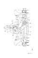
図1において、車両1は、右側サイドメンバ2および左側サイドメンバ3を備えており、右側サイドメンバ2および左側サイドメンバ3は、車両1の幅方向(以下、単に車幅方向という)に離れた位置に設置され、車両1の前後方向に延びている。
First, the configuration will be described.
In FIG. 1, the vehicle 1 includes a
右側サイドメンバ2および左側サイドメンバ3は、フロントクロスメンバ5およびフロントクロスメンバ5の後方に設置されるセンタクロスメンバ6によって連結されており、フロントクロスメンバ5およびセンタクロスメンバ6は、車幅方向に延びている。
The
本実施例のセンタクロスメンバ6は、本発明のクロスメンバを構成する。右側サイドメンバ2、左側サイドメンバ3、フロントクロスメンバ5およびセンタクロスメンバ6は、車両1の車体を構成する。
The
車両1にはパワーユニット10が設けられている。パワーユニット10は、内燃機関であるエンジン11と、エンジン11の図示しないクランクシャフトの回転速度を変速して出力する変速機12とを有する。
The vehicle 1 is provided with a
エンジン11は、クランクシャフトの回転中心軸11Cが車両1の前後方向に延びるように縦置きに設置されている。変速機12は、シフトアンドセレクト軸12Aを備えており、変速機12は、シフトアンドセレクト軸12Aが、軸回りに回転され、かつ、軸方向に移動されることで、シフトレンジが切換えられる。シフトアンドセレクト軸12Aは、変速機12の内部に設けられており、図1においては、変速機12から突出するシフトアンドセレクト軸12Aの後端部を示している。
The
変速機12にはプロペラシャフト13の前端部が連結されており(図2参照)、プロペラシャフト13は、変速機12から車両1の前後方向後方に延びている。変速機12の後方にはトランスファ装置14が設置されており、プロペラシャフト13の後端部は、トランスファ装置14の左側部分14Bの前側に連結されている。
The front end portion of the
これにより、変速機12の動力は、プロペラシャフト13を介してトランスファ装置14に伝達される。本実施例のプロペラシャフト13は、本発明の入力プロペラシャフトを構成する。
As a result, the power of the
トランスファ装置14には、右側部分14Aの前側にフロントプロペラシャフト15の後端部が連結されており、右側部分14Aの後側にリヤプロペラシャフト16の前端部が連結されている。トランスファ装置14は、左側部分14Bが回転中心軸11Cと同軸上に設置されるとともに、右側部分14Aが回転中心軸11Cに対して右側サイドメンバ2側に偏って設置されている。
In the
フロントプロペラシャフト15は、トランスファ装置14からパワーユニット10の車幅方向側方に向けて車両1の前後方向前方に延びている。
The
フロントプロペラシャフト15の前端部は、フロントディファレンシャル装置17に連結されている。フロントディファレンシャル装置17は、フロントプロペラシャフト15の動力を図示しない前側の左右のドライブシャフトを介して図示しない前輪に差動回転可能に伝達する。
The front end of the
リヤプロペラシャフト16の後端部は、リヤディファレンシャル装置18に連結されている。リヤディファレンシャル装置18は、リヤプロペラシャフト16の動力を図示しない後側の左右のドライブシャフトを介して図示しない後輪に差動回転可能に伝達する。
The rear end of the
トランスファ装置14は、プロペラシャフト13から伝達される動力を常時、リヤプロペラシャフト16に伝達する。
また、トランスファ装置14には切換レバー19(図2参照)が設けられており、運転者が切換レバー19を操作して、二輪駆動、もしくは、四輪駆動のいずれかが選択されると、トランスファ装置14は、プロペラシャフト13から伝達される動力をフロントプロペラシャフト15に伝達しない二輪駆動状態、もしくは、伝達する四輪駆動状態のいずれかに伝達経路を切換える。
The
Further, the
これにより、車両1は、二輪駆動または四輪駆動に切換えられるパートタイム4WDが実施される。なお、トランスファ装置14は、車両1を常時四輪で駆動するような動力の伝達経路となるように、すなわち、フルタイム4WDとなるように駆動されてもよい。
As a result, the vehicle 1 is subjected to part-time 4WD in which the vehicle 1 is switched to two-wheel drive or four-wheel drive. The
本実施例のフロントプロペラシャフト15は、本発明の前側プロペラシャフトを構成し、フロントディファレンシャル装置17は、本発明の前側ディファレンシャル装置を構成する。リヤプロペラシャフト16は、本発明の後側プロペラシャフトを構成し、リヤディファレンシャル装置18は、本発明の後側ディファレンシャル装置を構成する。
The
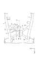
図5において、センタクロスメンバ6は、前側クロスメンバ24および後側クロスメンバ25を有し、前側クロスメンバ24および後側クロスメンバ25は、円形のパイプ材から構成されている。本実施例のセンタクロスメンバ6は、本発明のクロスメンバを構成する。
In FIG. 5, the
前側クロスメンバ24は、前側右端部24aが右側サイドメンバ2に連結されるとともに、前側左端部24bが左側サイドメンバ3に連結されており、車両1の平面視において前側右端部24aおよび前側左端部24bから回転中心軸11Cに向かって斜め後方に延び、中央部が後方に屈曲している。
In the
後側クロスメンバ25は、後側右端部25aが右側サイドメンバ2に連結されるとともに、後側左端部25bが左側サイドメンバ3に連結されており、車両1の平面視において後側右端部25aおよび後側左端部25bから回転中心軸11Cに向かって斜め前方に延び、中央部が前方に屈曲している。本実施例の回転中心軸11Cは、車両の前後方向の中心軸と同一軸であり、本発明の車両の前後方向の中心軸を構成する。
In the
車両1の平面視において、前側クロスメンバ24と後側クロスメンバ25とは、X形状になるように前側クロスメンバ24の屈曲方向の先端部24A(以下、屈曲先端部24Aという)と後側クロスメンバ25の屈曲方向の先端部25A(以下、屈曲先端部25Aという)とが車両1の前後方向に対向している。
In the plan view of the vehicle 1, the
本実施例の前側クロスメンバ24の屈曲先端部24Aとは、回転中心軸11Cに重なる前側クロスメンバ24の部位である。後側クロスメンバ25の屈曲先端部25Aとは、回転中心軸11Cに重なる後側クロスメンバ25の部位である。
The
屈曲先端部24Aおよび屈曲先端部25Aにはマウント取付ブラケット26が溶接等によって取付けられており、マウント取付ブラケット26は、屈曲先端部24A、25Aを跨がるようにして前側クロスメンバ24および後側クロスメンバ25に取付けられている。マウント取付ブラケット26は、後述するマウント部材を取付けるための平滑なマウント取付座面26Aを有する(図2参照)。
A
図2において、変速機12の後端にはマウントブラケット28が取付けられており、マウントブラケット28、マウント部材27を介してマウント取付ブラケット26に取付けられている。
In FIG. 2, a
マウント部材27は、ロアブラケット27A、アッパブラケット27Bおよび弾性体27Cを有する。
The
ロアブラケット27Aは、図示しないボルトによってマウント取付ブラケット26のマウント取付座面26Aに取付けられており、アッパブラケット27Bは、図示しないボルトによってマウントブラケット28に取付けられている。弾性体27Cは、ロアブラケット27Aとアッパブラケット27Bとを連結しており、ゴム等の弾性変形自在な材料から構成されている。
The
エンジン11は、右側部が図示しないマウント部材によって右側サイドメンバ2に、左側部が図示しないマウント部材によって左側サイドメンバ3に支持されており、マウント部材は、それぞれ図示しないゴム等の弾性体を備えている。
The
これにより、パワーユニット10は、マウント部材を介して右側サイドメンバ2および左側サイドメンバ3に弾性的に支持され、マウント部材27を介してセンタクロスメンバ6に弾性的に支持されている。
As a result, the
図1において、車両1には補強ブラケット32が設けられている。補強ブラケット32は、回転中心軸11Cと右側サイドメンバ2との間に位置する後側クロスメンバ25の部位と、右側サイドメンバ2とを連結している。
In FIG. 1, the vehicle 1 is provided with a reinforcing
トランスファ装置14は、変速機12に対して右側サイドメンバ2側に偏って、かつ、その前端部14aが後側右端部25aおよび後側左端部25bよりも前方に位置するよう設置されている。
The
トランスファ装置14の車幅方向の右側面には右側マウントブラケット33が連結されており、トランスファ装置14の車幅方向の左側面には左側マウントブラケット34が連結されている。本実施例の右側マウントブラケット33は、本発明の右側ブラケットを構成し、左側マウントブラケット34は、本発明の左側ブラケットを構成する。
The right
右側マウントブラケット33は、前後方向に延びる形状をしている。右側マウントブラケット33の後端部は、右側サイドメンバ2に連結されており、右側マウントブラケット33の前端部は、補強ブラケット32に連結されている。右側マウントブラケット33の前後方向の中央部は、トランスファ装置14に連結されている。
The right
補強ブラケット32は、後側クロスメンバ25の前側において、右側サイドメンバ2と後側クロスメンバ25とを連結している。これにより、右側マウントブラケット33の前側の連結点32Aは、補強ブラケット32に連結されている。
The reinforcing
左側マウントブラケット34は、左右方向に延びる形状をしている。左側マウントブラケット34の右端部は、トランスファ装置14に連結されており、左側マウントブラケット34の左端部は、左側サイドメンバ3に連結されている。
The
これにより、トランスファ装置14は、右側マウントブラケット33および左側マウントブラケット34を介して右側サイドメンバ2および左側サイドメンバ3に支持されている。本実施例の補強ブラケット32は、本発明の連結部材を構成する。
As a result, the
図4において、トランスファ装置14が偏る側の右側サイドメンバ2から後側クロスメンバ25の屈曲先端部25Aにおいて、後側クロスメンバ25にクランク状に折れ曲がる段差部25Bが形成されている。
In FIG. 4, from the
図4、図5において、段差部25Bは、屈曲先端部25A側の高位部25cから下方に折れ曲がった折り曲げ部25dと、折り曲げ部25dの下端部から右側サイドメンバ2に向かって延びる低位部25eとを有する。
In FIGS. 4 and 5, the stepped
図5において、低位部25eは、取付け面25fを有し、取付け面25fは、右側サイドメンバ2に対して折り曲げ部25d寄りに設けられている。取付け面25fには補強ブラケット32の左端部が溶接等によって連結されている。
In FIG. 5, the
図1、図2において、車両1にはシフト装置51が設けられている。シフト装置51は、シフトレバー52を備えており、シフトレバー52は、運転者によって操作される。
In FIGS. 1 and 2, the vehicle 1 is provided with a
シフトレバー52は、リンク部材53によってシフトアンドセレクト軸12Aに連結されている。リンク部材53の前端部にはシフトアンドセレクト軸12Aの後端部に連結される連結部53Aが設けられている。
The
リンク部材53は、シフトレバー52の動きに連動して軸回りに回転し、かつ、軸方向に移動し、シフトアンドセレクト軸12Aを軸回りに回転させ、かつ軸方向に移動させる。
The
シフト装置51は、シフトケース54を有し、シフトケース54は、リンク部材53を収容する収容部54Aと、収容部54Aから連結部53Aを挟み込むように二股状に突出する突出部54Bとを有し、リンク部材53を保持している。
The
突出部54Bの前端部は、取付ボス部54bで変速機12に揺動自在に支持されており、シフトケース54は、変速機12に対して取付ボス部54bを支点として上下方向に揺動自在である。
The front end portion of the protruding
収容部54Aの後端部にはピン部54aが設けられており(図2参照)、ピン部54aは、シフトブラケット55のボス部55Aに図示しない弾性体を介して摺動自在に支持されている。
A
図2において、シフトブラケット55は、マウント取付ブラケット26に取付けられている。シフトブラケット55は、底部を起点として後方に傾斜しながら上方に立ち上がるように延びている。
In FIG. 2, the
シフトブラケット55は、車両1の前後方向においてマウント部材27と並んで設置されており、マウント部材27およびマウントブラケット28の上方にシフトケース54が設置されている。
The
ボス部55Aは、シフトブラケット55の上部に設けられており、ピン部54aがボス部55Aに対して前後方向に摺動することにより、シフトケース54が車両1の前後方向に移動し、ボス部55Aに対してピン部54aの軸線回りに揺動する。
The
このように本実施例のシフト装置51は、シフトブラケット55を介してマウント取付ブラケット26に変位自在に支持されている。
As described above, the
本実施例のトランスファ装置14の支持構造によれば、センタクロスメンバ6は、前側クロスメンバ24および後側クロスメンバ25を備えている。前側クロスメンバ24は、前側右端部24aが右側サイドメンバ2に連結されるとともに、前側左端部24bが左側サイドメンバ3に連結され、車両1の平面視において前側右端部24aおよび前側左端部24bから回転中心軸11Cに向かって斜め後方に延び、中央部が後方に屈曲している。
According to the support structure of the
後側クロスメンバ25は、前側クロスメンバ24の後方に位置して後側右端部25a が右側サイドメンバ2に連結されるとともに、後側左端部25bが左側サイドメンバ3に連結され、車両1の平面視において後側右端部25aおよび後側左端部25bから回転中心軸11Cに向かって斜め前方に延び、中央部が前方に屈曲している。
The
車両1の平面視において前側クロスメンバ24と後側クロスメンバ25とがX形状になるように前側クロスメンバ24の屈曲先端部24Aと後側クロスメンバ25の屈曲先端部25Aとが車両1の前後方向に対向している。
The
さらに、前側クロスメンバ24および後側クロスメンバ25の屈曲先端部24A、25Aを跨がるようにして前側クロスメンバ24および後側クロスメンバ25にマウント取付ブラケット26が取付けられている。
Further, the
これにより、右側サイドメンバ2および左側サイドメンバ3と連結する前側クロスメンバ24と、右側サイドメンバ2および左側サイドメンバ3と連結する後側クロスメンバ25とがさらにマウント取付ブラケット26で連結される。
As a result, the
このため、前側クロスメンバ24と後側クロスメンバ25とが一体となったセンタクロスメンバ6が構築されて、前側クロスメンバ24と後側クロスメンバ25と右側サイドメンバ2および左側サイドメンバ3との連結部位がセンタクロスメンバ6としての連結部位として共有されて、センタクロスメンバ6の剛性を向上できる。
Therefore, a
また、マウント取付ブラケット26は、前側クロスメンバ24および後側クロスメンバ25の屈曲先端部24A、25Aで接触するため、直線部だけで接触する場合に比べて、接触範囲を広く取って設置でき、剛性を向上できる。
Further, since the
これに加えて、本実施例のトランスファ装置14の支持構造によれば、トランスファ装置14は、前端部14aが後側右端部25aと後側左端部25bよりも前方に位置するよう設置されており、右側マウントブラケット33および左側マウントブラケット34を介して右側サイドメンバ2および左側サイドメンバ3に支持されている。
In addition to this, according to the support structure of the
すなわち、後側クロスメンバ25は、車両1の平面視において、後側右端部25aおよび後側左端部25bから回転中心軸11Cに向かって斜め前方に延び、中央部が前方に屈曲している。
That is, in the plan view of the vehicle 1, the
これにより、後側クロスメンバ25の後方に、後側後端部25aと後側左端部25bと屈曲先端部25Aを頂点とする三角形状の空間が形成される。この三角形状の空間にトランスファ装置14の前端部14aを設置できる。
As a result, a triangular space having the rear
このため、右側マウントブラケット33の前端部と左側マウントブラケット34の左端部とを剛性の高いセンタクロスメンバ6の後側右端部25aと後側左端部25bにより接近した場所で右側サイドメンバ2および左側サイドメンバ3に支持することができる。
Therefore, the
このため、トランスファ装置14の支持剛性を向上できる。これに加えて、トランスファ装置14の振動を、図1の矢印aで示すように、右側マウントブラケット33から補強ブラケット32に伝達させた後に、後側クロスメンバ25および右側サイドメンバ2に分散して伝達させることができるとともに、左側マウントブラケット34から左側サイドメンバ3に伝達させることができる。
Therefore, the support rigidity of the
その後、矢印bで示すように、後側クロスメンバ25に伝達された振動は、前側クロスメンバ24および右側サイドメンバ2および左側サイドメンバ3に分散して伝達させることができる。
After that, as shown by the arrow b, the vibration transmitted to the
さらに、矢印cで示すように、前側クロスメンバ24に伝達された振動は、右側サイドメンバ2および左側サイドメンバ3に分散させることができる。
Further, as shown by the arrow c, the vibration transmitted to the
その後、後側クロスメンバ25に分散させた振動を、矢印cで示すように、屈曲先端部25A、屈曲先端部24Aを介して前側クロスメンバ24に分散して伝達させた後、右側サイドメンバ2および左側サイドメンバ3に分散して伝達させることができる。
Then, as shown by the arrow c, the vibration dispersed in the
このため、トランスファ装置14の振動が右側サイドメンバ2および左側サイドメンバ3の特定の部位に集中して伝達されることを抑制できるとともに、振動の大きさを低減でき、振動を乗員に感じ難くさせて車両1の乗り心地が悪化することを防止できる。
Therefore, it is possible to suppress the vibration of the
また、本実施例のトランスファ装置14の支持構造によれば、トランスファ装置14は、変速機12に対して右側サイドメンバ2側に偏って設置されている。
Further, according to the support structure of the
また、トランスファ装置14には、左側部分14Bの前側にプロペラシャフト13が連結され、右側部分14Aの前側にフロントプロペラシャフト15の後端部が連結され、さらに、右側部分14Aの後側にリヤプロペラシャフト16の前端部が連結されている。
Further, in the
このため、フロントプロペラシャフト15とリヤプロペラシャフト16が連結されるトランスファ装置14の右側部分14Aの振動が、プロペラシャフト13が連結されるトランスファ装置14の左側部分14Bの振動よりも大きい。
Therefore, the vibration of the
また、プロペラシャフト13とフロントプロペラシャフト15が連結されるトランスファ装置14の前側部分の振動が、リヤプロペラシャフト16が連結される後側部分の振動よりも大きい。
Further, the vibration of the front side portion of the
これに対して、本実施例のトランスファ装置14の支持構造は、右側マウントブラケット33の前側の連結点32Aが、後側クロスメンバ25の前側において右側サイドメンバ2と後側クロスメンバ25を連結する補強ブラケット32に連結されている。
On the other hand, in the support structure of the
これにより、補強ブラケット32によって後側クロスメンバ25と右側サイドメンバ2の剛性を高め、補強ブラケット32に右側サイドメンバ2の前側の連結点32Aを連結することができる。
As a result, the rigidity of the
このため、トランスファ装置14の支持剛性をより一層向上できる。この結果、トランスファ装置14の振動が右側サイドメンバ2および左側サイドメンバ3に伝達されることをより効果的に抑制できる。
Therefore, the support rigidity of the
また、本実施例のトランスファ装置14の支持構造によれば、トランスファ装置14が偏る側の右側サイドメンバ2から後側クロスメンバ25の屈曲先端部25Aにおいて、後側クロスメンバ25にクランク状に折れ曲がる段差部25Bが形成されている。
Further, according to the support structure of the
これにより、後側クロスメンバ25にクランク状に折れ曲がる段差部25Bを形成することにより、右側サイドメンバ2と屈曲先端部25Aとの間において後側クロスメンバ25の剛性を高くできる。
As a result, the rigidity of the
さらに、剛性が高い右側サイドメンバ2と屈曲先端部25Aとの間において、トランスファ装置14が右側マウントブラケット33を介して補強ブラケット32に連結されるので、トランスファ装置14の支持剛性をより一層向上できる。このため、トランスファ装置14の振動が右側サイドメンバ2および左側サイドメンバ3に伝達されることをより効果的に抑制できる。
Further, since the
また、本実施例のトランスファ装置14の支持構造によれば、段差部25Bは、高位部25cから下方に折れ曲がった折り曲げ部25dと、折り曲げ部25dの下端部から右側サイドメンバ2に向かって延び、補強ブラケット32が設けられる低位部25eとを有し、低位部25eは、補強ブラケット32が取付けられる取付け面25fを有する。
Further, according to the support structure of the
これに加えて、取付け面25fは、右側サイドメンバ2に対して折り曲げ部25d寄りに設けられている。
In addition to this, the mounting
これにより、直線部分よりも折り曲げ部25dの下端近傍、すなわち、折り曲げ部25dの曲げ終わりの部位に補強ブラケット32を連結することにより、補強ブラケット32の接合強度を向上できる。
As a result, the joint strength of the reinforcing
このため、右側マウントブラケット33を補強ブラケット32に高い剛性で支持することができ、結果的にトランスファ装置14の支持剛性を高くできる。この結果、トランスファ装置14の振動が右側サイドメンバ2および左側サイドメンバ3に伝達されることをより効果的に抑制できる。
Therefore, the right
また、本実施例の車両1によれば、シフトブラケット55が、マウント取付ブラケット26に取付けられているので、エンジン11の振動や車両1の振動によって変速機12からマウントブラケット28を介してマウント部材27に伝達される振動や荷重を屈曲先端部24A、25Aから前側右端部24a、25aおよび前側左端部24b、25bに分散させて右側サイドメンバ2および左側サイドメンバ3に伝達できる。
Further, according to the vehicle 1 of the present embodiment, since the
このため、パワーユニット10の振動が車両1の特定部位に集中することを防止して、パワーユニット10の振動が車体に伝達することを防止できる。これにより、振動を乗員に感じ難くでき、乗員の乗り心地を良好に保つことができる。
Therefore, it is possible to prevent the vibration of the
また、本実施例の車両1によれば、マウント取付ブラケット26には弾性変形可能なマウント部材27が取付けられており、パワーユニット10とマウント部材27とがマウントブラケット28を介して連結されている。
Further, according to the vehicle 1 of the present embodiment, an elastically
このため、変速機12をマウントブラケット28およびマウント部材27を介して剛性が高いマウント取付ブラケット26に安定して支持することができる。
Therefore, the
したがって、エンジン11の振動や車両1の振動によって変速機12からマウントブラケット28を介してマウント部材27に振動が伝達されたときに、マウント部材27によって振動を減衰し、マウント取付ブラケット26からセンタクロスメンバ6を経て右側サイドメンバ2、3に伝達される振動を抑制できる。
Therefore, when the vibration is transmitted from the
なお、本実施例のトランスファ装置14は、変速機12に対して右側サイドメンバ2側に偏っているが、変速機12に対して左側サイドメンバ3側に偏っていてもよい。この場合には、トランスファ装置14の車幅方向の左側面に右側マウントブラケット33と同一形状の左側マウントブラケットを設ける。
Although the
さらに、後側クロスメンバ25の前側において、左側サイドメンバ3と後側クロスメンバ25とを補強ブラケット32によって連結し、右側マウントブラケット33と同一形状の左側マウントブラケットの前側の連結点を、補強ブラケット32に連結してもよい。
Further, on the front side of the
また、トランスファ装置14が変速機12に対して左側サイドメンバ3側に偏っている場合には、トランスファ装置14が偏る側の左側サイドメンバ3から後側クロスメンバ25の屈曲先端部25Aにおいて、後側クロスメンバ25にクランク状に折れ曲がる段差部を形成してもよい。
When the
また、本実施例の補強ブラケット32は、後側クロスメンバ25と右側サイドメンバ2とを連結しているが、前側クロスメンバ24と右側サイドメンバ2とを連結してもよい。
Further, although the reinforcing
また、トランスファ装置14が変速機12に対して左側サイドメンバ3側に偏っている場合には、補強ブラケット32は、後側クロスメンバ25と左側サイドメンバ3とを連結してしてもよく、前側クロスメンバ24と左側サイドメンバ3とを連結してもよい。
Further, when the
本発明の実施例を開示したが、当業者によっては本発明の範囲を逸脱することなく変更が加えられうることは明白である。すべてのこのような修正および等価物が次の請求項に含まれることが意図されている。 Although the embodiments of the present invention have been disclosed, it is clear that some skilled in the art can make changes without departing from the scope of the present invention. All such modifications and equivalents are intended to be included in the following claims.
1...車両、2...右側サイドメンバ、3...左側サイドメンバ、6...センタクロスメンバ(クロスメンバ)、11C...回転中心軸(車両の前後方向の中心軸)12...変速機、13...プロペラシャフト(入力プロペラシャフト)、14...トランスファ装置、14a...前端部(トランスファ装置の前端部)、15...フロントプロペラシャフト(前側プロペラシャフト)、16...リヤプロペラシャフト(後側プロペラシャフト)、17...フロントディファレンシャル装置(前側ディファレンシャル装置)、18...リヤディファレンシャル装置(後側ディファレンシャル装置)、24...前側クロスメンバ、24A...屈曲方向の先端部、24a...前側右端部、24b...前側左端部、25...後側クロスメンバ、25A...屈曲方向の先端部、25B...段差部、25a...後側右端部、25b...後側左端部、25c...高位部、25d...折り曲げ部、25e...低位部、25f...取付け面、32...補強ブラケット(連結部材)、32A...連結点(連結部材の前側の連結点)、33...右側マウントブラケット(右側ブラケット)、34...左側マウントブラケット(左側ブラケット) 1 ... Vehicle, 2 ... Right side member, 3 ... Left side member, 6 ... Center cross member (cross member), 11C ... Rotation center axis (center axis in the front-rear direction of the vehicle) 12 ... Transmission, 13 ... Propeller shaft (input propeller shaft), 14 ... Transfer device, 14a ... Front end (front end of transfer device), 15 ... Front propeller shaft (front propeller) Shaft), 16 ... rear propeller shaft (rear propeller shaft), 17 ... front differential device (front differential device), 18 ... rear differential device (rear differential device), 24 ... front cross Member, 24A ... Tip in bending direction, 24a ... Front right end, 24b ... Front left end, 25 ... Rear cross member, 25A ... Tip in bending direction, 25B .. Stepped portion, 25a ... rear right end, 25b ... rear left end, 25c ... high, 25d ... bent, 25e ... low, 25f ... mounting surface, 32 ... Reinforcing bracket (connecting member), 32A ... Connecting point (connecting point on the front side of the connecting member), 33 ... Right side mount bracket (right side bracket), 34 ... Left side mount bracket (left side bracket)
Claims (4)
車両の幅方向に離れて車両の前後方向に延びる右側サイドメンバおよび左側サイドメンバを連結するクロスメンバを有し、
前記クロスメンバは、前側右端部および前側左端部がそれぞれ前記右側サイドメンバおよび前記左側サイドメンバに連結され、車両の平面視において前記前側右端部および前記前側左端部から車両の前後方向の中心軸に向かって後方に屈曲する前側クロスメンバと、
前記前側クロスメンバの後方に位置して後側右端部および後側左端部がそれぞれ前記右側サイドメンバおよび前記左側サイドメンバに連結され、車両の平面視において前記後側右端部および前記後側左端部から車両の前後方向の中心軸に向かって前方に屈曲する後側クロスメンバとを備えており、
車両の平面視において前記前側クロスメンバと前記後側クロスメンバとがX形状になるように前記前側クロスメンバの屈曲方向の先端部と前記後側クロスメンバの屈曲方向の先端部とが車両の前後方向に対向しており、
前記トランスファ装置は、その前端部が前記後側右端部と前記後側左端部よりも前方に位置するよう設置されており、
前記トランスファ装置は、右側ブラケットおよび左側ブラケットを介して前記右側サイドメンバおよび前記左側サイドメンバに支持されていることを特徴とするトランスファ装置の支持構造。 Installed behind the transmission, the power of the transmission can be transmitted via the input propeller shaft, and the power transmitted from the transmission can be transmitted to the front differential device via the front propeller shaft. It is a support structure of the transfer device that can be transmitted to the rear differential device via the rear propeller shaft.
It has a cross member that connects the right side member and the left side member that extend in the front-rear direction of the vehicle apart from the width direction of the vehicle.
In the cross member, the front right end and the front left end are connected to the right side member and the left side member, respectively, and from the front right end and the front left end to the central axis in the front-rear direction of the vehicle in the plan view of the vehicle. With the front cross member that bends backward toward
The rear right end and the rear left end are connected to the right side member and the left side member, respectively, located behind the front cross member, and the rear right end and the rear left end are viewed in a plan view of the vehicle. It is equipped with a rear cross member that bends forward toward the central axis in the front-rear direction of the vehicle.
The front and rear ends of the front cross member in the bending direction and the tip of the rear cross member in the bending direction are front and rear of the vehicle so that the front cross member and the rear cross member have an X shape in a plan view of the vehicle. Facing the direction,
The transfer device is installed so that its front end is located in front of the rear right end and the rear left end.
A support structure for a transfer device, wherein the transfer device is supported by the right side member and the left side member via a right bracket and a left bracket.
前記右側ブラケットは、前記トランスファ装置の車幅方向の右側面に設けられており、
前記左側ブラケットは、前記トランスファ装置の車幅方向の左側面に設けられており、
前記トランスファ装置が偏る側に設置される前記右側ブラケットまたは前記左側ブラケットの前側の連結点は、前記後側クロスメンバの前側において前記右側サイドメンバと前記後側クロスメンバまたは前記前側クロスメンバとを連結する連結部材、若しくは、前記後側クロスメンバの前側において前記左側サイドメンバと前記後側クロスメンバまたは前記前側クロスメンバとを連結する連結部材に連結されていることを特徴とする請求項1に記載のトランスファ装置の支持構造。 The transfer device is installed biased to the right side member side or the left side member side with respect to the transmission,
The right bracket is provided on the right side surface of the transfer device in the vehicle width direction.
The left bracket is provided on the left side surface of the transfer device in the vehicle width direction.
Connection point of the front of the right bracket and the left bracket is provided on a side where the transfer device is biased, the connecting and said right side member and the rear-side cross member or the front cross member in front of the rear cross member connecting member, or, according to claim 1, characterized in that it is connected to a connecting member for connecting the rear said and left side member side cross member or the front cross member in front of the rear cross member Support structure of the transfer device.
前記取付け面は、前記右側サイドメンバまたは前記左側サイドメンバに対して前記折り曲げ部寄りに設けられていることを特徴とする請求項3に記載のトランスファ装置の支持構造。 The stepped portion has a bent portion which is bent downward from the higher portion, extending from the lower end portion of the bent portion toward the right side member or the left side member, a low portion having a mounting surface on which the connecting member is attached Prepared
The support structure for a transfer device according to claim 3, wherein the mounting surface is provided closer to the bent portion with respect to the right side member or the left side member.
Priority Applications (1)
| Application Number | Priority Date | Filing Date | Title |
|---|---|---|---|
| JP2017191302A JP6922626B2 (en) | 2017-09-29 | 2017-09-29 | Support structure of transfer device |
Applications Claiming Priority (1)
| Application Number | Priority Date | Filing Date | Title |
|---|---|---|---|
| JP2017191302A JP6922626B2 (en) | 2017-09-29 | 2017-09-29 | Support structure of transfer device |
Publications (3)
| Publication Number | Publication Date |
|---|---|
| JP2019064440A JP2019064440A (en) | 2019-04-25 |
| JP2019064440A5 JP2019064440A5 (en) | 2020-10-22 |
| JP6922626B2 true JP6922626B2 (en) | 2021-08-18 |
Family
ID=66338882
Family Applications (1)
| Application Number | Title | Priority Date | Filing Date |
|---|---|---|---|
| JP2017191302A Active JP6922626B2 (en) | 2017-09-29 | 2017-09-29 | Support structure of transfer device |
Country Status (1)
| Country | Link |
|---|---|
| JP (1) | JP6922626B2 (en) |
Family Cites Families (2)
| Publication number | Priority date | Publication date | Assignee | Title |
|---|---|---|---|---|
| JPH08164761A (en) * | 1994-12-12 | 1996-06-25 | Mitsubishi Motors Corp | Body mounting structure of transfer unit |
| JP2004034877A (en) * | 2002-07-05 | 2004-02-05 | Fuji Heavy Ind Ltd | Power unit supporting structure of vehicle |
-
2017
- 2017-09-29 JP JP2017191302A patent/JP6922626B2/en active Active
Also Published As
| Publication number | Publication date |
|---|---|
| JP2019064440A (en) | 2019-04-25 |
Similar Documents
| Publication | Publication Date | Title |
|---|---|---|
| US7967102B2 (en) | Steering shaft support structure and vehicle | |
| JP2001328410A (en) | Saddle riding type vehicle | |
| TWI617484B (en) | Vehicle | |
| JP6153049B1 (en) | Three-wheeled vehicle | |
| US8998216B2 (en) | Vehicle | |
| JP2010173602A (en) | Working vehicle | |
| JP2008162502A (en) | Shaft driving vehicle and its swing arm structure | |
| JP5618856B2 (en) | Motorcycle body frame | |
| US20220119069A1 (en) | Leaning vehicle | |
| US20030146593A1 (en) | Rear wheel suspension device for saddle ride vehicle | |
| JP6922625B2 (en) | Support structure of shift device | |
| JP6922626B2 (en) | Support structure of transfer device | |
| US7922204B2 (en) | Vibration-isolating device for steering wheel of traveling working vehicle with wheel steering mechanism | |
| JP6251615B2 (en) | Suspension device for saddle riding type vehicle | |
| JP2003212147A (en) | Frame for riding tractor | |
| CN108930783B (en) | Supporting structure of gearshift | |
| JP6988341B2 (en) | Power unit mount structure | |
| JP6958198B2 (en) | Fuel filter mounting structure | |
| JP2000351330A (en) | Riding type lawn mower | |
| JP6953968B2 (en) | Support structure of shift device | |
| JP2007030810A (en) | Low-floor type vehicle | |
| JP7275549B2 (en) | Support structure for vehicle power unit | |
| CN108928391A (en) | The mounting structure of Package power | |
| CN108928234B (en) | Supporting structure of gearshift | |
| JP6107845B2 (en) | Vehicle powertrain support structure |
Legal Events
| Date | Code | Title | Description |
|---|---|---|---|
| A621 | Written request for application examination |
Free format text: JAPANESE INTERMEDIATE CODE: A621 Effective date: 20200902 |
|
| A521 | Written amendment |
Free format text: JAPANESE INTERMEDIATE CODE: A523 Effective date: 20200910 |
|
| A977 | Report on retrieval |
Free format text: JAPANESE INTERMEDIATE CODE: A971007 Effective date: 20210526 |
|
| TRDD | Decision of grant or rejection written | ||
| A01 | Written decision to grant a patent or to grant a registration (utility model) |
Free format text: JAPANESE INTERMEDIATE CODE: A01 Effective date: 20210629 |
|
| A61 | First payment of annual fees (during grant procedure) |
Free format text: JAPANESE INTERMEDIATE CODE: A61 Effective date: 20210712 |
|
| R151 | Written notification of patent or utility model registration |
Ref document number: 6922626 Country of ref document: JP Free format text: JAPANESE INTERMEDIATE CODE: R151 |