JP6920882B2 - Scalable finite element simulation of addition manufacturing - Google Patents
Scalable finite element simulation of addition manufacturing Download PDFInfo
- Publication number
- JP6920882B2 JP6920882B2 JP2017100213A JP2017100213A JP6920882B2 JP 6920882 B2 JP6920882 B2 JP 6920882B2 JP 2017100213 A JP2017100213 A JP 2017100213A JP 2017100213 A JP2017100213 A JP 2017100213A JP 6920882 B2 JP6920882 B2 JP 6920882B2
- Authority
- JP
- Japan
- Prior art keywords
- finite element
- simulated
- heat flux
- processor
- finite
- Prior art date
- Legal status (The legal status is an assumption and is not a legal conclusion. Google has not performed a legal analysis and makes no representation as to the accuracy of the status listed.)
- Active
Links
Images


Classifications
-
- G—PHYSICS
- G06—COMPUTING; CALCULATING OR COUNTING
- G06F—ELECTRIC DIGITAL DATA PROCESSING
- G06F30/00—Computer-aided design [CAD]
- G06F30/20—Design optimisation, verification or simulation
- G06F30/23—Design optimisation, verification or simulation using finite element methods [FEM] or finite difference methods [FDM]
-
- B—PERFORMING OPERATIONS; TRANSPORTING
- B22—CASTING; POWDER METALLURGY
- B22F—WORKING METALLIC POWDER; MANUFACTURE OF ARTICLES FROM METALLIC POWDER; MAKING METALLIC POWDER; APPARATUS OR DEVICES SPECIALLY ADAPTED FOR METALLIC POWDER
- B22F10/00—Additive manufacturing of workpieces or articles from metallic powder
- B22F10/20—Direct sintering or melting
-
- B—PERFORMING OPERATIONS; TRANSPORTING
- B22—CASTING; POWDER METALLURGY
- B22F—WORKING METALLIC POWDER; MANUFACTURE OF ARTICLES FROM METALLIC POWDER; MAKING METALLIC POWDER; APPARATUS OR DEVICES SPECIALLY ADAPTED FOR METALLIC POWDER
- B22F10/00—Additive manufacturing of workpieces or articles from metallic powder
- B22F10/80—Data acquisition or data processing
-
- B—PERFORMING OPERATIONS; TRANSPORTING
- B33—ADDITIVE MANUFACTURING TECHNOLOGY
- B33Y—ADDITIVE MANUFACTURING, i.e. MANUFACTURING OF THREE-DIMENSIONAL [3-D] OBJECTS BY ADDITIVE DEPOSITION, ADDITIVE AGGLOMERATION OR ADDITIVE LAYERING, e.g. BY 3-D PRINTING, STEREOLITHOGRAPHY OR SELECTIVE LASER SINTERING
- B33Y50/00—Data acquisition or data processing for additive manufacturing
- B33Y50/02—Data acquisition or data processing for additive manufacturing for controlling or regulating additive manufacturing processes
-
- G—PHYSICS
- G06—COMPUTING; CALCULATING OR COUNTING
- G06F—ELECTRIC DIGITAL DATA PROCESSING
- G06F2111/00—Details relating to CAD techniques
- G06F2111/10—Numerical modelling
-
- Y—GENERAL TAGGING OF NEW TECHNOLOGICAL DEVELOPMENTS; GENERAL TAGGING OF CROSS-SECTIONAL TECHNOLOGIES SPANNING OVER SEVERAL SECTIONS OF THE IPC; TECHNICAL SUBJECTS COVERED BY FORMER USPC CROSS-REFERENCE ART COLLECTIONS [XRACs] AND DIGESTS
- Y02—TECHNOLOGIES OR APPLICATIONS FOR MITIGATION OR ADAPTATION AGAINST CLIMATE CHANGE
- Y02P—CLIMATE CHANGE MITIGATION TECHNOLOGIES IN THE PRODUCTION OR PROCESSING OF GOODS
- Y02P10/00—Technologies related to metal processing
- Y02P10/25—Process efficiency
Description
関連出願の相互参照
本出願は、2016年5月20日に出願した米国特許仮出願第62/339,203号の利益を主張するものである。上記出願の教示全体は、参照により本明細書に組み込まれる。
Cross-reference to related applications This application claims the benefit of US Patent Provisional Application No. 62 / 339,203, filed May 20, 2016. The entire teachings of the above application are incorporated herein by reference.
3D印刷技術の勢いは、近年において著しい。多くのプリンタ製造業者が存在し、新しい会社が一夜にして現れるようである。この新しい開発の波にも関わらず、多くの場合(ほとんどではないにしても)、技術の信頼性は限られ、印刷または付加製造(「AM」)された部品は、従来の技術を用いて製造された部品と比べたときに、標準より下の強度および疲労寿命に繋がる欠陥を被る。このマイナスの側面は、技術の広がりを大幅に制限する。プロセスへの洞察をもたらし、それによりAM部品の品質の向上における進歩が達成され得るような、コンピュータシミュレーションが求められる。 The momentum of 3D printing technology has been remarkable in recent years. There are many printer manufacturers and new companies seem to emerge overnight. Despite this new wave of development, in many cases (most, if not), the reliability of the technology is limited, and printed or additively manufactured (“AM”) parts use conventional technology. It suffers from substandard strength and fatigue life defects when compared to manufactured parts. This negative aspect severely limits the spread of technology. Computer simulation is required that provides insight into the process, thereby achieving progress in improving the quality of AM components.
付加製造プロセスの多くの物理現象関連の側面は、鋳造および溶接などの従来の製造技術のいくつかと同様である。高温の流体状態の材料が加えられ、次いでそれが冷却する。付加製造において材料は、溶融状態で増分的に加えられ、または移動する熱源(例えばレーザ)によって溶融状態にもたらされ、その後に連続的に進展する表面上で冷却が生じる。AMに伴う、特に金属製作に伴う追加の課題は、製造時に対処しなければならない時間および長さスケールにおける大きな差異に関係し、「処置」ゾーンにおける非常に局在した、急速に進展する物理現象の一方、全体の部品に対する製造プロセスは数時間またはおそらく数日かかる。 Many physics-related aspects of the additive manufacturing process are similar to some of the traditional manufacturing techniques such as casting and welding. A hot fluid state material is added, which then cools. In addition manufacturing, the material is brought to the molten state by an incrementally added or moving heat source (eg, a laser) in the molten state, followed by cooling on a continuously evolving surface. The additional challenges associated with AM, especially with metal production, relate to large differences in time and length scales that must be addressed during manufacturing, and are highly localized, rapidly evolving physical phenomena in the "treatment" zone. On the other hand, the manufacturing process for the entire part can take hours or perhaps days.
付加製造プロセスのいくつかの側面をシミュレーションするための数値的技法を開発する努力は数多くあり、研究者から応用研究商業事業体までの科学者およびエンジニアのいくつかのグループに広がる。このようなプロセスをコンピュータシミュレーションによって捕捉/予測する難しさは多くあり、以下を含む:(1)溶融/固体化物理現象(ミリ秒)、および典型的な部品の全体の製造時間(機械上の数時間の印刷)の非常に異なる時間スケール、(2)溶融プールに関連付けられる数ミクロンから、典型的な部品をモデル化するのに必要な数百ミリメートルまでの、スケール長さの広い範囲、(3)高度に異方性な材料の最終特性(最終的熱処理の前の)に繋がる、「処置」ゾーンの周りの急速に進展する高い温度勾配、(4)適切なモデルが使用されると仮定して上記のすべてを捕捉するためには、このようなプロセスをモデル化するために、非常に大きなシミュレーション時間が通常必要となる。 Efforts to develop numerical techniques for simulating some aspects of the additive manufacturing process are numerous and extend to several groups of scientists and engineers, from researchers to applied research commercial entities. The difficulties of capturing / predicting such processes by computer simulation are many and include: (1) melting / solidification physics (milliseconds), and the overall manufacturing time of typical parts (on the machine). Very different time scales (several hours of printing), (2) a wide range of scale lengths, from the few microns associated with the melt pool to the hundreds of millimeters needed to model typical parts, ( 3) Rapidly evolving high temperature gradient around the "treatment" zone, which leads to the final properties of the highly anisotropic material (before the final heat treatment), (4) assuming a suitable model is used. To capture all of the above, it usually takes a very large amount of simulation time to model such a process.
これらすべての課題に対処するために、新規な数値的方式を開発することが必要になる。以下は既存の技術の例であり、そのそれぞれは上述の問題を解決しない。 To address all these challenges, it will be necessary to develop new numerical methods. The following are examples of existing technologies, each of which does not solve the above problems.
3DSIMは、有限要素に基づく効率的な数値シミュレーション技術を開発すると主張する会社である。3DSIMの方法は、先進の金属モデル化構造挙動を活用しながら、適応型メッシュ微細化/粗大化技法をうまく利用していると思われる。(例えば、非特許文献1参照)。この技術は、レーザ溶融/焼結AMアプリケーションを対象としており、「処置」ゾーン(例えば現在のレーザ位置)における自動化されたメッシュ微細化技法を使用する。しかしこれは、実際のレーザ経路情報、および部品全体にわたるリコータ/スプレッダバーを活用していない。その結果、部品全体に対する対流および放射による全体的な冷却は、結果として正確さおよび/予測性を失う。さらにメッシュの自動化された微細化/粗大化は、解析が複数のCPU上(特に多数のCPU上)で並行して実行されるとき、全体の計算性能に対してマイナス要素を有する。 3DSIM is a company that claims to develop efficient numerical simulation technology based on finite elements. The 3DSIM method appears to make good use of adaptive mesh miniaturization / coarsening techniques while leveraging advanced metal modeling structural behavior. (See, for example, Non-Patent Document 1). This technique is intended for laser melting / sintering AM applications and uses automated mesh miniaturization techniques in the "treatment" zone (eg, the current laser position). However, it does not take advantage of the actual laser path information and the recorder / spreader bar across the component. As a result, overall convection and radiation cooling of the entire component results in loss of accuracy and / predictability. Further, the automated miniaturization / coarsening of the mesh has a negative factor on the overall computational performance when the analysis is executed in parallel on a plurality of CPUs (particularly on a large number of CPUs).
PANCOMPUTINGは、有限要素をベースとするソリューションを活用する会社の他の例である。PANCOMPUTINGの方法も適応型メッシュ微細化技法を組み込み、印刷プロセス時の望ましくない歪みを予測することが可能である。(例えば、非特許文献2参照)。技術は3DSIMと同様であり、同様な制限に直面する。 PANCOMPUTING is another example of a company that leverages finite element based solutions. The PANCOMPUTING method also incorporates adaptive mesh miniaturization techniques to predict unwanted distortions during the printing process. (See, for example, Non-Patent Document 2). The technology is similar to 3DSIM and faces similar limitations.
米国国立研究所もまたこのトピックに投資しており、ロスアラモスおよびローレンス・リバモアが活動をリードしている。ロスアラモスでは、長期にわたり存在してきた鋳造シミュレーションソフトウェアが、現在、AMプロセスを数値的に研究するために適応化/再利用化されている(www.lanl.govで利用可能なTruchas鋳造ソフトウェアを参照)。ローレンス・リバモアでは、粉末から液体へ、固体への相転移の複雑な物理現象を微小規模で対処するために、包括的なシミュレーション技術が開発されており、非常に小さな部品に対する残留応力を予測することを試みている。(例えば、非特許文献3参照)。米国国立研究所は、部品レベルシミュレーションに対する正確な予測には焦点を当てていないように思われる。代わりに彼等は、現実的な部品に関する限り、全体的な挙動には十分な注意を払わずに、非常に小さなスケールのモデルにおける基本的挙動の理解に多くの努力を費やしているように思われる。 The US National Laboratory has also invested in this topic, with Los Alamos and Lawrence Livermore leading the way. In Los Alamos, long-standing casting simulation software is now being adapted / reused for numerical study of the AM process (see Truchas casting software available at www.lanl.gov). .. Lawrence Livermore has developed comprehensive simulation techniques to address the complex physics of powder-to-liquid to solid phase transitions on a small scale, predicting residual stresses for very small components. I'm trying to do that. (See, for example, Non-Patent Document 3). The US National Laboratory does not appear to focus on accurate predictions for component-level simulations. Instead, they seem to spend a lot of effort understanding the basic behavior in very small scale models, without paying close attention to the overall behavior, as far as the realistic parts are concerned. Is done.
このトピックを調査している研究者は、ここで包括的なやり方で列挙するには数が多すぎる。多くは文献(例えば、非特許文献4参照)で述べられているものなど、もともと溶接または鋳造のために開発された古い既存のモデルを活用している。より最近の研究(例えば、非特許文献5参照)は、大体、非常に有用で実用的な、高性能の材料構造挙動モデルに焦点を当てている。すべての種類の研究者はまた国立研究所と同様に、スケーラブルな予測的ソリューションに対する部品レベルシミュレーションに焦点を当てていない。部品レベルの提示が含められたとき、現実的な部品への対処における技術の不足に対応するために、形状に関連付けられた幾何形状は大幅に単純化される。 Researchers investigating this topic are too numerous to list here in a comprehensive manner. Many utilize older existing models originally developed for welding or casting, such as those described in the literature (see, eg, Non-Patent Document 4). More recent studies (see, eg, Non-Patent Document 5) have largely focused on highly useful, practical, high performance material structure behavior models. Researchers of all kinds also, like national laboratories, do not focus on component-level simulations for scalable predictive solutions. When part-level presentations are included, the geometry associated with the shape is greatly simplified to address the lack of technology in dealing with realistic parts.
熱処理に関係するアプリケーションの数値モデル化は、金属の場合において、モデル化されつつある部品の全体にわたって、冶金学的変形のモデル化において重要な関連性を有する。(例えば、非特許文献6参照)。熱処理ソフトウェアパッケージは、多様な観点からAMプロセスシミュレーションに対して非常に関連性があるが、厳しい制限を受け、局所的な熱的側面(レーザ加熱など)をシミュレーションする、および付加製造プロセスの進展する表面を管理する能力が不足する。 Numerical modeling of applications related to heat treatment, in the case of metals, has important relevance in the modeling of metallurgical deformations throughout the part being modeled. (See, for example, Non-Patent Document 6). Heat treatment software packages are highly relevant to AM process simulation from various perspectives, but are subject to severe restrictions, simulating local thermal aspects (such as laser heating), and advancing additional manufacturing processes. Insufficient ability to control the surface.
従って様々な数値モデル化技術を開発するための数多くの先行する努力にも関わらず、これらの開発に関連するいくつかのかなり顕著な制限が存在する。 Therefore, despite the numerous prior efforts to develop various numerical modeling techniques, there are some fairly significant limitations associated with these developments.
本発明の実施形態は、部品レベルシミュレーションのための数値的方法を用いた、正確な、スケーラブル、および予測的3D印刷シミュレーションをもたらす。本発明の1つの例示の実施形態は、実世界オブジェクトの付加製造をシミュレーションする方法である。方法によればプロセッサは、任意密度の任意メッシュを用いて、実世界オブジェクトの表現を複数の有限要素に離散化し、有限要素は実世界オブジェクトの幾何学的部分の表現であり、有限要素はメモリに記憶される。実世界オブジェクトを製造するために実世界付加製造装置によって用いられることになる実世界の付加製造シーケンスは、時間の関数として決定され、付加製造シーケンスは複数の時間ステップを含み、有限要素によって表される実世界オブジェクトの部分を製造する順序を示す。付加製造シーケンスの各時間ステップに対して、プロセッサは、(i)付加製造シーケンスに従って、上記有限要素のうちの有限要素の任意の幾何学的層の製造をシミュレーションし、(ii)付加製造シーケンスに従って、有限要素の層の対応する位置におけるシミュレーションされた熱流束のシーケンスを決定し、シミュレーションされた熱流束は、層の製造をシミュレーションするときに、層内の、シミュレーションされる付加製造装置の熱源の経路および強度を考慮し、(iii)層に対応する有限要素に関連して、シミュレーションされた熱流束の表現をメモリに記憶し、(iv)シミュレーションされる製造された層を有する各有限要素に対して、有限要素の現在露出されている部分的表面積を決定し、有限要素の現在露出されている部分的表面積に基づいて、有限要素の冷却をシミュレーションし、メモリにおいて、有限要素のシミュレーションされた冷却に基づいて、有限要素に関連付けられたシミュレーションされた熱流束の表現を更新する。 Embodiments of the present invention provide accurate, scalable, and predictive 3D printing simulations using numerical methods for component level simulations. One exemplary embodiment of the invention is a method of simulating the additive manufacturing of real-world objects. According to the method, the processor uses an arbitrary mesh of arbitrary density to disperse the representation of a real-world object into multiple finite elements, where the finite element is a representation of the geometric part of the real-world object and the finite element is memory. Is remembered in. The real-world additional manufacturing sequence that will be used by the real-world additional manufacturing equipment to manufacture real-world objects is determined as a function of time, and the additional manufacturing sequence contains multiple time steps and is represented by finite elements. Shows the order in which parts of real-world objects are manufactured. For each time step of the addition manufacturing sequence, the processor simulates the production of any geometric layer of the finite element of the finite elements according to (i) the addition manufacturing sequence and (ii) according to the addition manufacturing sequence. Determine the sequence of simulated heat flux at the corresponding positions of the finite element layer, and the simulated heat flux is the heat source of the simulated additional manufacturing equipment within the layer when simulating the production of the layer. Considering the path and intensity, the simulated heat flux representation is stored in memory in relation to the finite element corresponding to the (iii) layer, and (iv) to each finite element having a simulated manufactured layer. In contrast, the currently exposed partial surface area of the finite element was determined, the cooling of the finite element was simulated based on the currently exposed partial surface area of the finite element, and the finite element was simulated in memory. Update the representation of the simulated heat flux associated with the finite element based on the cooling.
本発明の他の例示の実施形態も、実世界オブジェクトの付加製造をシミュレーションする方法であり、表現として実世界オブジェクトの複数の有限要素を記憶したメモリと通信するプロセッサが関わる。方法は、実世界オブジェクトを製造するために実世界付加製造装置によって用いられるように実世界の付加製造シーケンスを取得し、付加製造シーケンスは複数の時間ステップを含む。付加製造シーケンスの各時間ステップに対してプロセッサは、(i)付加製造シーケンスに従って、上記複数の有限要素のうちの有限要素の任意の幾何学的層の製造をシミュレーションし、(ii)付加製造シーケンスに従って、層の対応する位置における1または複数のシミュレーションされた熱流束を決定し、シミュレーションされた熱流束は、層の製造をシミュレーションするときに、層内の、シミュレーションされる付加製造装置の熱源の経路および強度を考慮し、(iii)層に対応する有限要素に関連して、シミュレーションされた熱流束の表現をメモリに記憶し、(iv)シミュレーションされる製造された層を有する各有限要素に対して、有限要素の現在露出されている部分的表面積を決定し、有限要素の現在露出されている部分的表面積に基づいて、有限要素の冷却をシミュレーションし、メモリにおいて、有限要素のシミュレーションされた冷却に基づいて、有限要素の熱流束の表現を更新する。 Another exemplary embodiment of the invention is also a method of simulating the additive production of a real world object, involving a processor communicating with a memory storing a plurality of finite elements of the real world object as a representation. The method acquires a real-world additional manufacturing sequence as used by a real-world additional manufacturing apparatus to manufacture a real-world object, and the additional manufacturing sequence comprises multiple time steps. For each time step of the additional manufacturing sequence, the processor simulates the manufacturing of any geometric layer of the finite element of the plurality of finite elements according to (i) the additional manufacturing sequence, and (ii) the additional manufacturing sequence. According to, one or more simulated heat fluxes at the corresponding positions of the layer are determined, and the simulated heat flux is used as the heat source of the simulated additional manufacturing equipment in the layer when simulating the production of the layer. Considering the path and strength, the simulated heat flux representation is stored in memory in relation to the finite element corresponding to the (iii) layer, and (iv) to each finite element having a simulated manufactured layer. In contrast, the currently exposed partial surface area of the finite element was determined, the cooling of the finite element was simulated based on the currently exposed partial surface area of the finite element, and the finite element was simulated in memory. Update the representation of the heat flux of finite elements based on cooling.
上記の方法のいくつかの実施形態において、有限要素の現在露出されている部分的表面積を決定するステップは、メモリに記憶された有限要素に基づいて、他のアクティブ有限要素表面ファセットに隣接して位置しない有限要素の表面ファセットを決定するステップを含むことができる。 In some embodiments of the above method, the step of determining the currently exposed partial surface area of a finite element is adjacent to other active finite element surface facets based on the finite element stored in memory. It can include the step of determining the surface area of a finite element that is not located.
上記の方法のいくつかの実施形態において、層の対応する位置におけるシミュレーションされた熱流束のシーケンスを決定するステップは、付加製造シーケンスに従って、層に対して、シミュレーションされた付加製造ツールの経路を解析するステップを含むことができ、シミュレーションされた熱流束のシーケンスを決定するステップは、所与のシミュレーションされた熱流束に対して、対応する層の一部分における熱源の強度および持続時間を決定するステップを含むことができる。 In some embodiments of the above method, the step of determining the sequence of simulated heat flux at the corresponding positions of the layer analyzes the path of the simulated heat flux for the layer according to the accretionary manufacturing sequence. The step of determining the sequence of simulated heat flux can include the step of determining the intensity and duration of the heat source in a portion of the corresponding layer for a given simulated heat flux. Can include.
上記の方法のいくつかの実施形態において、有限要素に関連付けられたシミュレーションされた熱流束の表現を更新するステップは、有限要素の部分的体積および有限要素の部分的ファセット領域を決定し、メモリに記憶するステップを含むことができる。このような実施形態において、有限要素の熱流束の表現を更新するステップは、有限要素のシミュレーションされた冷却、有限要素の決定された部分的体積、および有限要素の部分的ファセット領域に基づいて、有限要素を製造するために用いられるシミュレーションされる基板の状態を決定するステップを含むことができ、または各有限要素に対して、隣接した有限要素のリスト、ならびにそれらの隣接した有限要素の部分的体積および部分的ファセット領域を、メモリに記憶するステップをさらに含むことができる。 In some embodiments of the above method, the step of updating the representation of the simulated heat flux associated with a finite element determines the partial volume of the finite element and the partial facet area of the finite element and puts it in memory. It can include steps to memorize. In such an embodiment, the step of updating the representation of the finite element heat flux is based on the simulated cooling of the finite element, the determined partial volume of the finite element, and the partial facet region of the finite element. It can include steps to determine the state of the simulated substrate used to manufacture the finite elements, or for each finite element, a list of adjacent finite elements, as well as a partial of those adjacent finite elements. It may further include a step of storing the volume and partial facet area in memory.
本発明の他の例示の実施形態は、実世界オブジェクトの付加製造をシミュレーションするためのシステムであり、データストア、ハードウェアプロセッサ、および交差モジュールを含む。データストアは、実世界オブジェクトの複数の有限要素を記憶し、有限要素は、任意密度の任意メッシュに従った、実世界オブジェクトの幾何学的部分の表現である。ハードウェアプロセッサは、データストアと通信し、複数の時間ステップを含む付加製造シーケンスに従って、実世界オブジェクトを製造する、実世界付加製造装置をシミュレーションするように構成される。交差モジュールは、ハードウェアプロセッサおよびデータストアと通信し、付加製造シーケンスの特定の時間ステップを前提として、(i)付加製造シーケンスの特定の時間ステップにおいて、シミュレーションされる付加製造装置によって影響を受ける有限要素に対する、付加された体積および部分的ファセット領域を決定し、(ii)付加製造シーケンスの特定の時間ステップにおいて、有限要素に対する熱流束事象および位置を決定するように構成される。ハードウェアプロセッサは、実世界付加製造装置をシミュレーションすることにおいて、付加製造シーケンスの各時間ステップに対して、(i)時間ステップを交差モジュールにもたらし、(ii)交差モジュールから、付加製造シーケンスの特定の時間ステップにおいて、シミュレーションされる付加製造装置によって影響を受ける有限要素に対する、付加された体積および部分的ファセット領域を受け取り、(iii)影響を受けた有限要素の各有限要素に対して、有限要素に対する付加された体積および部分的ファセット領域を用いて、データストアに記憶された有限要素を更新し、有限要素に対する付加された体積および部分的ファセット領域に基づいて、有限要素の現在露出されている部分的表面積を決定し、(iv)交差モジュールから、有限要素に対する熱流束事象および関連付けられた位置を受け取り、(v)受け取られた各熱流束事象に対して、関連付けられた位置に基づいて、データストアに記憶された、対応する有限要素に関連付けられたノード熱流束を更新し、(vi)有限要素の現在露出されている部分的表面積に基づいて、各有限要素の冷却を決定し、(vii)ノード熱流束に対応する有限要素の決定された冷却に基づいて、各ノード熱流束を更新するように構成される。 Another exemplary embodiment of the invention is a system for simulating the augmentation manufacturing of real-world objects, including a data store, a hardware processor, and an intersecting module. A data store stores multiple finite elements of a real-world object, which is a representation of the geometric part of a real-world object according to an arbitrary mesh of arbitrary density. The hardware processor is configured to communicate with a data store and simulate a real-world additive manufacturing device that manufactures real-world objects according to an additional manufacturing sequence that includes multiple time steps. The intersection module communicates with the hardware processor and data store and is subject to specific time steps in the additional manufacturing sequence, and (i) finitely affected by the simulated additional manufacturing equipment in the specific time steps in the additional manufacturing sequence. It is configured to determine the added volume and partial facet region for the element and (ii) determine the heat flux event and position for the finite element at a particular time step in the addition manufacturing sequence. In simulating a real-world additional manufacturing apparatus, the hardware processor brings (i) a time step to the crossing module for each time step of the additional manufacturing sequence, and (ii) identifies the additional manufacturing sequence from the crossing module. In the time step of, it receives the added volume and partial facet region for the finite element affected by the simulated additional manufacturing equipment, and (iii) for each finite element of the affected finite element, the finite element. The finite element stored in the data store is updated with the added volume and partial facet area for the finite element, and the finite element is currently exposed based on the added volume and partial facet area for the finite element. Determine the partial surface area, (iv) receive the heat flux event and associated position for the finite element from the cross module, and (v) for each received heat flux event, based on the associated position. Update the node heat flux associated with the corresponding finite element stored in the data store, and (vi) determine the cooling of each finite element based on the currently exposed partial surface area of the finite element. vii) It is configured to update each node heat flux based on the determined cooling of the finite element corresponding to the node heat flux.
いくつかの実施形態においてデータストアは、データストアに記憶された各有限要素に対して、隣接した有限要素のリストを含むことができ、プロセッサは、所与の有限要素に対する、隣接した有限要素のリストに基づいて、所与の有限要素の現在露出されている部分的表面積を決定するように構成され得る。このような実施形態においてデータストアは、隣接した有限要素の各リスト内の各隣接した有限要素に対して、隣接した有限要素がアクティブであるかどうかの表示をさらに含むことができ、プロセッサは、所与の有限要素に対する、隣接した有限要素のリスト、および各隣接した有限要素がアクティブであるかどうかの関連付けられた表示に基づいて、所与の有限要素の現在露出されている部分的表面積を決定するように構成され得る。 In some embodiments, the data store may include a list of adjacent finite elements for each finite element stored in the data store, and the processor may include an adjacent finite element for a given finite element. Based on the list, it can be configured to determine the currently exposed partial surface area of a given finite element. In such an embodiment, the data store can further include an indication of whether the adjacent finite element is active for each adjacent finite element in each list of adjacent finite elements. The currently exposed partial surface area of a given finite element, based on a list of adjacent finite elements for a given finite element and an associated indication of whether each adjacent finite element is active. It can be configured to determine.
いくつかの実施形態においてハードウェアプロセッサは、交差モジュールに、シミュレーションされる付加製造装置のノード座標をもたらすようにさらに構成されることができ、または有限要素のシミュレーションされた冷却、および熱流束事象に基づいて、有限要素を製造するために用いられる、シミュレーションされる基板の状態を決定し、データストアに記憶するようにさらに構成され得る。 In some embodiments, the hardware processor can be further configured to provide the intersection module with the node coordinates of the simulated additional manufacturing equipment, or for simulated cooling of finite elements, and heat flux events. Based on this, it may be further configured to determine the state of the simulated substrate used to manufacture the finite element and store it in the data store.
いくつかの実施形態において交差モジュールは、付加製造シーケンスの所与の時間ステップにおいて、シミュレーションされる付加製造装置のシミュレーションされる熱源の、強度および経路に基づいて、熱流束事象を決定するように構成され得る。 In some embodiments, the cross module is configured to determine a heat flux event based on the intensity and path of the simulated heat source of the simulated addition manufacturing equipment at a given time step in the addition manufacturing sequence. Can be done.
上記は、異なる図にわたって類似の参照記号は同じ部分を指す添付の図面に示される、以下の本発明の例示の実施形態のより具体的な説明から明らかになるであろう。図面は必ずしも原寸に比例して描かれておらず、代わりに本発明の実施形態を例示することに重点が置かれる。
以下は本発明の例示の実施形態の説明である。 The following is a description of an exemplary embodiment of the present invention.
本発明の実施形態は、部品レベルシミュレーションのための数値的方法を用いた、正確な、スケーラブル、および予測的3D印刷シミュレーションをもたらし、以下の方法論を含む。 Embodiments of the present invention provide accurate, scalable, and predictive 3D printing simulations using numerical methods for component level simulations, including the following methodologies:
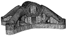
メッシュ化:3D印刷プロセスがそれに対してモデル化されることになる、部品の幾何学的形状は、最初に有限要素により離散化される。任意メッシュ密度の任意メッシュが用いられ得る。このようなメッシュを用いることは、通常AM製作される部品は一様なメッシュが実際には可能でない非常に複雑な形状を有するので、解析プロセスの能率化を大きく改善する。任意メッシュ化を有するこのような複雑な形状の例は、図1に示される。 Meshing: The geometry of the part, where the 3D printing process will be modeled for it, is first discretized by the finite elements. Any mesh of arbitrary mesh density can be used. The use of such a mesh greatly improves the efficiency of the analysis process, as parts that are usually AM-manufactured have very complex shapes that are not actually possible with a uniform mesh. An example of such a complex shape with arbitrary meshing is shown in FIG.
機械情報:部品を製造することになる3D印刷機械に関係する情報(例えば粉末再コーティングシーケンス、レーザ走査経路、印刷ヘッドの材料堆積など)は、物理的機械によって用いられるような実際のデータから、正確さを失うことなく前処理される。従ってモデル化プロセスに関する限り、印刷機械が実際に用いることになる情報を簡略化することによって、正確さを失うことはない。 Machine Information: Information related to the 3D printing machine that will manufacture the part (eg, powder recoating sequence, laser scanning path, printhead material deposition, etc.) comes from actual data as used by the physical machine. Preprocessed without loss of accuracy. Therefore, as far as the modeling process is concerned, accuracy is not lost by simplifying the information that the printing machine will actually use.
交差:幾何学的意味において、有限要素メッシュを、印刷機械のツールの経路情報に「交差」させるために、「交差モジュール」と呼ばれる構成要素が用いられる。例えば粉末床リコータの現在の表面高さの情報が、任意の所与の時間において交差される要素の部分的要素体積を計算するために用いられ得る。図2は有限要素200を示し、シミュレーション時の2つの異なる時点における、2つの異なる部分的体積を示す。Pdは付加製造方向を示す。平面Piは、層Liにおける有限要素200の充填レベルを示す。平面Pjは、Liより後の時点での層Ljにおける有限要素200の充填レベルを示す。さらに、交差された要素のファセットの部分的領域が計算される。例えば有限要素が層Liまで充填されたとき、多角形A,B,Cの部分的領域は、I1,I2,B,Cとなる。交差は、部品のもとの形状、または解析時の部品の予測される変形された/歪まされた形状の現在の形状に基づくことができる。多くの実施形態では交差モジュールは、ソフトウェアを用いて実施され得る。
Intersection: In a geometric sense, a component called an "intersection module" is used to "intersect" a finite element mesh with the path information of a printing machine tool. For example, information on the current surface height of a powder bed recoater can be used to calculate the partial element volume of the intersecting elements at any given time. FIG. 2 shows the
漸進的要素アクティブ化:上述の部分的要素体積に基づいて、シミュレーション時の任意の所与のポイントにおいて、任意の特定の有限要素は、物質で完全に充填される、物質で部分的に充填される、または完全に空のいずれかである。交差モジュールは、この進展を精密なやり方で追跡する。部分的体積積分技法は、これらの部分的体積のそれぞれにおける様々な材料相または状態(例えば粉末、溶融液体状態、固体状態)を考慮するために使用される。任意の時間増分シーケンスが可能になる。例えば図2において、有限要素200のI1,I2,I3,I4多角形(Pi)の周りの薄いスライスは生の状態の材料(例えば粉末または液体)となり、それより下は固体(または部分的に液体)となり、それより上は空となるであろう。漸進的アクティブ化技術は、所与の要素に生の状態(例えば粉末)の材料が付加され得る、初期温度の厳密な指定を可能にする。これは、要素の積分ポイントの現在の温度と、所望の初期温度との差に基づいた、自動的に計算される等価な潜熱流束を適用することによって達成される。
Gradual element activation: Based on the partial element volume described above, at any given point during simulation, any particular finite element is fully filled with material, partially filled with material. Or completely empty. The intersection module tracks this evolution in a precise manner. Partial volume integral techniques are used to account for various material phases or states (eg, powder, molten liquid state, solid state) in each of these partial volumes. Any time increment sequence is possible. For example, in FIG. 2, a thin slice around the I 1 , I 2 , I 3 , I 4 polygon (P i ) of the
漸進的加熱計算:任意の時点において特定の熱バーストは、レーザ走査をベースとするAMプロセスに対して図3に例示されるように、熱源の実際の経路を考慮することによって計算される。図3は、上面交差平面(例えば、図2からのPj、上から見て)に関連付けられた断面図を示す。時間および空間の両方における加熱源の正確な表現のために、任意の数の加熱事象(図3に丸印305として示される、所与の位置における熱流束のシーケンスとして特性付けられる)が、要素ごと層ごとに計算される。図3において経路310は、機械情報に従ってレーザがとる経路を表す。図3の特定の実施形態において熱流束は、三角形の層の上のレーザの各通過によってカバーされる領域、およびレーザの強度に基づいて計算される。任意の時間増分シーケンスが可能になる。
Gradual heating calculation: At any given time, a particular heat burst is calculated by considering the actual path of the heat source, as illustrated in FIG. 3 for a laser scan based AM process. FIG. 3 shows a cross-sectional view associated with an at-grade intersection plane (eg, Pj from FIG. 2, viewed from above). For an accurate representation of the heat source in both time and space, any number of heating events (characterized as a sequence of heat flux at a given position, shown as
対流および放射による漸進的冷却:上記で論じられた部分的ファセット領域積分は、任意の所与の有限要素離散化に対する冷却に関係する熱流束の非常に精密な算定を可能にする。図4に示されるように多角形I1,I2,I3,I4および側方の多角形B,I2,I1,Cの位置および表面積は、現在外部に露出された、製作されつつある部品の領域を、非常に精密に考慮するように、任意の時点において計算される。次いで放射および対流冷却は、正確に計算された領域に対して良好にモデル化されることができる。 Gradual cooling by convection and radiation: The partial facet domain integrals discussed above allow a very precise calculation of the heat flux associated with cooling for any given finite element discretization. As shown in FIG. 4, the positions and surface areas of the polygons I 1 , I 2 , I 3 , I 4 and the lateral polygons B, I 2 , I 1 , C are currently exposed and manufactured. It is calculated at any point in time to take into account the area of the part that is being created with great precision. Radiation and convection cooling can then be well modeled for the accurately calculated region.
本発明の実施形態は、多くの種類の付加製造プロセスの部品レベルシミュレーションに対する、高度にスケーラブルなソリューションをもたらす。これはSLM、DLM、Polyjet、インクジェット、およびFDM技術を含むが、それらに限定されない。いくつかの特定の利点は以下を含む: Embodiments of the present invention provide a highly scalable solution for component level simulation of many types of additive manufacturing processes. This includes, but is not limited to, SLM, DLM, Polyjet, inkjet, and FDM techniques. Some specific benefits include:
(1)独立および任意メッシュ化を可能にする。複雑な部品は、機械に関連付けられた層(または任意の他の)情報を用いて、複雑な幾何形状を分割することを必要とせずに、好ましい有限要素(FE)メッシャを用いて、通常のようにメッシュ化されることができる。非常に複雑な部品に対してこの手法は、特別なメッシュ化技術を開発すること、または固有の人工的な、応力を集中させるものの影響を被るボクセルをベースとする手法に頼ることを必要とせずに、製作されつつある部品の形状のずっと良好な近似を可能にする。 (1) Allows independent and arbitrary meshing. Complex parts usually use the preferred finite element (FE) mesher with the layer (or any other) information associated with the machine, without the need to divide the complex geometry. Can be meshed like this. For very complex parts, this technique does not require the development of special meshing techniques or the reliance on voxel-based techniques that are affected by the inherent artificial, stress-concentrating ones. In addition, it allows a much better approximation of the shape of the part being manufactured.
(2)実際のツールの経路および実際の印刷時間(レーザ、電子ビーム、堆積ヘッド、リコータバーなど)を、これらの経路が実際の機械で用いられるかのように考慮する。これは実際の生産部品の複雑な幾何形状に従う、数千の層、数百万のセグメントを用いたツールの経路を含む。ユーザは、機械情報の近似を試みる必要はない。 (2) Consider the actual tool path and the actual printing time (laser, electron beam, deposition head, recorder bar, etc.) as if these paths were used in a real machine. This includes a tool path with thousands of layers and millions of segments that follow the complex geometry of the actual production part. The user does not have to try to approximate the machine information.
(3)計算性能と正確さとの間を緩和するためのスケーラビリティ。単純に、非常に正確な基準ソリューションのためには、非常に微細なメッシュを用いることができ(通常は小さな部品に対して)、または計算上効率的なソリューションのためには、より粗大なメッシュを用いることができる(通常は、より大きな部品に対して)。FEメッシュの全範囲が用いられ得る。時間ステップサイズ、過渡挙動、数値的収束、および計算性能などの、各技術の固有の利点から恩恵を受けるように、陰的および陽的時間積分方式の両方に適用可能である。 (3) Scalability to relax between computational performance and accuracy. Simply, for a very accurate reference solution, a very fine mesh can be used (usually for small parts), or for a computationally efficient solution, a coarser mesh. Can be used (usually for larger parts). The entire range of FE mesh can be used. It is applicable to both implicit and explicit time integration schemes, benefiting from the unique advantages of each technology, such as time step size, transient behavior, numerical convergence, and computational performance.
(4)所与のFEメッシュに対して「交差」技術は、異なる材料(粉末、溶融液体状態、および固体状態などの生の状態)の体積が精密に考慮されるので、任意の量の体積ベースの積分(いずれのFEソフトウェアにおいても典型的な動作)に対して、最良の結果を生じる。このソリューションは、必要に応じて追加の自動化されたメッシュ微細化技法と共に用いられ得る。 (4) For a given FE mesh, the "crossing" technique precisely considers the volume of different materials (raw states such as powder, molten liquid state, and solid state), so any amount of volume. It produces the best results for the base integral (typical behavior in any FE software). This solution can be used with additional automated mesh miniaturization techniques as needed.
(5)局在した加熱効果が非常に良好に捕捉される。このような熱事象の位置、それらの強度、およびそれらの持続時間は、メッシュを用いた熱源(高速で移動するレーザスポットなど)の「交差」計算により、メッシュ選択に直接依存せずに、非常に精密に捕捉される。 (5) The localized heating effect is captured very well. The location of such thermal events, their intensities, and their duration are very independent of mesh selection, due to the "intersection" calculation of heat sources using meshes (such as fast-moving laser spots). Precisely captured.
(6)対流および放射熱損失は、精密に計算された表面積上で算定され、これは任意の所与のメッシュ選択に対して、可能な限り精密になり得る。上述のように、冷却の大部分が生じる上面を精密に計算することにより、および部分的ファセット計算と一緒に、アクティブ/非アクティブ隣接要素のリストを保持することによって、冷却がその上で生じる表面積の正確さは、メッシュ離散化の選択をはるかに超える。 (6) Convection and radiant heat loss are calculated on a precisely calculated surface area, which can be as precise as possible for any given mesh selection. As mentioned above, the surface area on which cooling occurs by precisely calculating the top surface on which most of the cooling occurs, and by keeping a list of active / inactive adjacencies along with the partial facet calculation. The accuracy of is far beyond the choice of mesh discretization.
全体的な付加製造ワークフローは、図5に示されるように、より多数のビルディングブロックを含む。この関連において、本明細書で述べられる態様は、図5において丸で囲まれた2つのビルディングブロックに関連付けられる。より詳しくは、2つの丸で囲まれたブロックは、図6に示されるフローチャート600に従うことができる。チャートはアーキテクチャ上の詳細を含み、時間遷移熱伝達ソリューションのためのラグランジュFEコードに基づく。時間進行シーケンスは、時間遷移ソリューションにおいて通常遭遇する、典型的な増分シーケンスに従う。
The overall additive manufacturing workflow includes a larger number of building blocks, as shown in FIG. In this regard, the embodiments described herein are associated with two building blocks circled in FIG. More specifically, the two circled blocks can follow the
図6のフローチャート600は、その機能を実行するために以下のように、4つの主要なビルディングブロックを含む。
(1)解析ごとに1回の機能605、これは機械情報を、有限要素メッシュに「交差」させることに関連付けられた、効率的データ構造をセットアップする。
(1) One
(2)機械データとFEメッシュとの間の幾何学的交差に関連付けられたデータはデータベースに記憶され、これは交差モジュール610の一部とすることができる。上述のようなFEメッシュとの粉末床交差上面、およびレーザ加熱バーストなどの、データの記憶および実際の計算をトリガするために、いくつかのアプリケーションプログラミングインターフェース(API)がもたらされ得る。
(2) The data associated with the geometric intersection between the machine data and the FE mesh is stored in the database, which can be part of the
(3)部品を印刷するために必要な時間にわたる時間増分ループは、610、615、620および625に示される。これらは、陰時間積分ソリューションにおいて、非線形FEモデル化に関連付けられた通常のニュートン−ラプソンループに、どれだけ多くの反復を要しても、増分ごとに1回トリガされる。機械データとFEメッシュとの間の実際の交差の計算はここで生じ、メッシュのもとの構成、または(結合された熱伝達−応力解析の場合)現在の変形された構成を用いることができる。必要なデータは記憶され、計算され、最終的に必要に応じてデータベースから抽出される。 (3) Time increment loops over the time required to print a part are shown in 610, 615, 620 and 625. These are triggered once per increment in the negative time integration solution, no matter how many iterations the normal Newton-Rapson loop associated with nonlinear FE modeling requires. The calculation of the actual intersection between the machine data and the FE mesh occurs here and the original configuration of the mesh or (in the case of combined heat transfer-stress analysis) the current modified configuration can be used. .. The required data is stored, calculated and finally extracted from the database as needed.
(4)最後に、FEコードにおいて通常のように反復時に、必要な情報を専門のデータベースから取り出すことによって、外部熱流束(上記で詳述されたように加熱と冷却の両方)を適用するためのいくつかの計算が存在する。これらの計算は610および630に示される。 (4) Finally, to apply external heat flux (both heating and cooling as detailed above) by retrieving the required information from a specialized database during iterations as usual in the FE code. There are several calculations of. These calculations are shown in 610 and 630.
上記の構成要素を実施するためのいくつかの例示のデータ構造は、有限要素データ構造を含むことができ、これはシミュレーションされることになるオブジェクトの有限要素に対して、(1)要素に関連付けられたノード番号、(2)要素に対する3Dにおけるノード座標、および(3)ノード変位(要素の変形された構成を計算するために用いられる)を記憶する。このようなデータ構造は、メモリにおいて、製作されることになる部品の要素の集合を表すために用いられ得る。このようなデータ構造はまた、メモリにおいて、印刷プロセス時に部品を固定するために用いられる支持物の要素の集合を表すために用いられ得る。 Some exemplary data structures for implementing the above components can include finite element data structures, which are associated with (1) elements for the finite elements of the object to be simulated. It stores the node number given, (2) the node coordinates in 3D with respect to the element, and (3) the node displacement (used to calculate the deformed configuration of the element). Such a data structure can be used in memory to represent a set of elements of parts that will be manufactured. Such data structures can also be used in memory to represent a set of support elements used to secure parts during the printing process.
上記の構成要素を実施するための例示のデータ構造はまた、機械処理情報を含むことができ、これは原材料到来情報を表すデータ、および移動する熱源情報を表すデータ(例えばレーザ、UVランプなど)を記憶する。原材料到来を表すデータは例えば、(1)原材料堆積構成要素の幾何形状(例えばノズル、スプレッダバー、インクジェット印刷バンクなど)、(2)材料堆積構成要素が材料の堆積を開始したときの時間および位置座標、および(3)材料堆積構成要素が材料の堆積を終了したときの時間および位置座標を、含むことができる。移動する熱源を表すデータは例えば、(1)熱源の幾何形状、(2)熱源がオンにされたときの時間および位置座標、および(3)熱源がオフにされたときの時間および位置座標を含むことができる。 An exemplary data structure for carrying out the above components can also include machining information, which represents raw material arrival information and data representing moving heat source information (eg, lasers, UV lamps, etc.). Remember. Data representing the arrival of raw materials include, for example, (1) the geometry of the raw material deposition component (eg nozzle, spreader bar, inkjet printing bank, etc.), (2) the time and position when the material deposition component begins to deposit material. Coordinates and (3) time and position coordinates when the material deposition component completes material deposition can be included. The data representing the moving heat source is, for example, (1) the geometry of the heat source, (2) the time and position coordinates when the heat source is turned on, and (3) the time and position coordinates when the heat source is turned off. Can include.
上記の例示のデータ構造を用いて、本発明の例示の実施形態による交差モジュールは、シミュレーションの各増分において、機械処理情報と有限要素との間の交差を計算し、記憶することができる。このような交差は、(1)各有限要素に対して、材料堆積痕跡と有限要素との間の交差を計算し、(2)痕跡と有限要素の端部との交差の座標を記憶し、(3)増分に対して、対応する有限要素内の付加された原材料の質量中心を計算し、(4)各有限要素に対して、各移動する熱源の痕跡と、有限要素の端部との間の交差を計算し、(5)対応する要素において各移動する熱源によって費やされた時間の持続時間、および対応する要素において熱源によって覆われた領域の中心の位置を記憶すること、によって計算され得る。 Using the above illustrated data structure, the intersection module according to the exemplary embodiment of the invention can calculate and store the intersection between machine processing information and finite elements at each increment of simulation. Such intersections (1) calculate the intersection between the material deposition trace and the finite element for each finite element, and (2) store the coordinates of the intersection between the trace and the end of the finite element. (3) Calculate the mass center of the added raw material in the corresponding finite element for the increment, (4) For each finite element, the trace of each moving heat source and the end of the finite element. Calculated by calculating the intersection between (5) the duration of time spent by each moving heat source in the corresponding element, and the position of the center of the area covered by the heat source in the corresponding element. Can be done.
図6のチャート600は、熱伝達ソリューションのための陰時間積分ソリューションに関連付けられるが、非常に似たワークフローが陽時間積分熱伝達ソリューションに関連付けられ得る。 Chart 600 of FIG. 6 is associated with a negative time integration solution for a heat transfer solution, but a very similar workflow can be associated with a positive time integration heat transfer solution.
計算性能:使用され得る、より長い時間増分(モデル化されるために必要な大きな物理時間を前提とすると、より少ない増分)のために、通常のワークフローが陰時間積分方式を用いることを想定するのは自然であるが、陽積分ソリューションは、処置ゾーンにおける、より高速な過渡現象を捕捉できるという固有の利点を提供する。陽時間積分FEコードは通常、多数のコアに対して、陰時間積分のものより良好にスケーリングできるという事実と組み合わされて、陽時間積分ソリューションは非常に魅力的となる。現実の部品に対するベンチマーク実行は、この点を実証している。部品歪みおよび残留応力に関心がある場合は、構造解析に対して同様なワークフローチャートが当てはまる。 Computational performance: For longer time increments that can be used (less increments given the large physical time required to be modeled), assume that a normal workflow uses the implicit time integration method. Although natural, explicit integration solutions offer the unique advantage of being able to capture faster transients in the treatment zone. The positive-time integral FE code is usually combined with the fact that it can scale better for a large number of cores than that of the negative-time integral, which makes the explicit time integral solution very attractive. Benchmarking on real-world components demonstrates this point. If you are interested in component strain and residual stress, a similar work flow chart applies to structural analysis.
上記の議論は、最初に熱伝達問題を解いて、その後に後続の応力解析における計算温度履歴の適用が続く、シーケンシャルワークフローを中心としている。これは通常、温度進展は応力に強く影響を及ぼす(例えば熱膨張、および温度が影響する相転移)が、機械的応力および歪みは大部分は温度進展に影響を及ぼさないので可能であるが、現在、結合された温度−応力ソリューションは容易に利用可能である。 The above discussion focuses on sequential workflows, where the heat transfer problem is solved first, followed by the application of the calculated temperature history in subsequent stress analyzes. This is usually possible because temperature evolution has a strong effect on stress (eg, thermal expansion and temperature-affected phase transitions), but mechanical stress and strain do not affect temperature evolution to a large extent. Currently, combined temperature-stress solutions are readily available.
デジタル処理環境
図7は本発明の例示の実施形態による、付加製造プロセスをシミュレーションするために用いられ得る、コンピュータベースのシステム720の簡略化されたブロック図である。システム720はバス725を備える。バス725は、システム720の様々な構成要素の間の相互接続部として働く。バス725には、キーボード、マウス、ディスプレイ、タッチスクリーンオーバーレイ、スピーカ、カメラ、センサフィード、コントローラなどの様々な入力および出力デバイスをシステム720に接続するための、入力/出力デバイスインターフェース728が接続される。中央処理装置(CPU)722はバス725に接続され、コンピュータ命令の実行をもたらす。メモリ727は、コンピュータ命令を実行するために用いられるデータに対する揮発性記憶をもたらす。ストレージ726は、オペレーティングシステム(図示せず)などのソフトウェア命令のために、不揮発性記憶をもたらす。具体的にはメモリ727および/またはストレージ726は、例えば図6に関連して詳述されたような付加製造プロセスをシミュレーションするための方法を実施するプログラム命令、および/またはモジュール600、605、610、615、620、625、および630により構成される。システム720はまた、クラウド、広域ネットワーク(WAN)およびローカルエリアネットワーク(LAN)を含む、当技術分野で知られている任意の多様なネットワークに接続するための、ネットワークインターフェース721を備える。
Digital Processing Environment FIG. 7 is a simplified block diagram of a computer-based
本明細書で述べられる例示の実施形態は、多くの異なる方法において実施され得ることが理解されるべきである。いくつかの例において、本明細書で述べられる様々な方法、システム、および装置は、それぞれ物理的、仮想、またはハイブリッド汎用コンピュータによって実施され得る。コンピュータシステム720は、例えばCPU722による実行のために、ソフトウェア命令をメモリ727または不揮発性ストレージ726にロードすることによって、本明細書で述べられる方法を実行する機械に変換され得る。
It should be understood that the exemplary embodiments described herein can be implemented in many different ways. In some examples, the various methods, systems, and devices described herein can be implemented by physical, virtual, or hybrid general purpose computers, respectively. The
図8は、本発明の実施形態が実施され得る、コンピュータネットワーク環境860を示す。コンピュータネットワーク環境860において、サーバ831は、通信ネットワーク832を通じて、クライアント833a〜nにリンクされる。環境860は、クライアント833a〜nが、単独でまたはサーバ831と一緒に、本明細書で上述されたモジュールおよび/または方法のいずれか(例えば図6に関連して詳述された、例えば方法および/またはモジュール600、605、610、615、620、625、および630)を、実行することを可能にするために用いられ得る。上述の例示の実施形態は、多くの異なる方法で実施され得ることが理解されるべきである。いくつかの例において、本明細書で述べられる様々な方法および機械は、それぞれ物理的、仮想、またはハイブリッド汎用コンピュータ、またはコンピュータ環境860などのコンピュータネットワーク環境によって実施され得る。
FIG. 8 shows a
実施形態およびその態様は、ハードウェア、ファームウェア、またはソフトウェアの形で実施され得る。ソフトウェアとして実施される場合、ソフトウェアは、プロセッサがソフトウェアまたはその命令のサブセットをロードすることを可能にするように構成された、任意の非一時的コンピュータ可読媒体に記憶され得る。次いでプロセッサは、命令を実行し、本明細書で述べられるやり方で動作する、または装置に動作させるように構成される。 The embodiments and embodiments may be implemented in the form of hardware, firmware, or software. When implemented as software, the software may be stored on any non-transitory computer-readable medium configured to allow the processor to load the software or a subset of its instructions. The processor is then configured to execute instructions and operate in the manner described herein, or to operate the device.
さらにファームウェア、ソフトウェア、ルーチン、または命令は、データプロセッサの一定の処置および/または機能を行うものとして本明細書で述べられ得る。しかし本明細書に含まれるこのような記述は単に便宜上であり、このような処置は実際には、ファームウェア、ソフトウェア、ルーチン、命令などを実行するコンピューティングデバイス、プロセッサ、コントローラ、または他のデバイスから生じることが理解されるべきである。 Further, firmware, software, routines, or instructions may be described herein as performing certain actions and / or functions of a data processor. However, such statements contained herein are for convenience only, and such actions are in fact from a computing device, processor, controller, or other device that executes firmware, software, routines, instructions, and so on. It should be understood that it will occur.
フロー図、ブロック図、およびネットワーク図は、より多いまたは少ない要素を含むことができ、異なって構成され、または異なって表され得ることが理解されるべきである。しかしさらに、いくつかの実装形態は、実施形態の実行を示すブロックおよびネットワーク図、ならびにいくつかのブロックおよびネットワーク図が、特定の方法で実施されることを決定付け得ることが理解されるべきである。 It should be understood that flow diagrams, block diagrams, and network diagrams can contain more or fewer elements and can be configured or represented differently. But further, it should be understood that some implementations can determine that the blocks and network diagrams that show the execution of the embodiments, as well as some blocks and network diagrams, are implemented in a particular way. be.
それに従って他の実施形態もまた、多様なコンピュータアーキテクチャ、物理的、仮想、クラウドコンピュータ、および/またはそれらの何らかの組み合わせにおいて実施されることができ、従って本明細書で述べられるデータプロセッサは、説明の目的のためのみであり、実施形態を限定するものではない。 Accordingly, other embodiments can also be implemented in a variety of computer architectures, physical, virtual, cloud computers, and / or any combination thereof, and thus the data processors described herein are described. It is for the purpose only and does not limit the embodiment.
本明細書において記載されたすべての特許、公開された出願、および参考資料の教示は、それらの全体が参照により組み込まれる。 The teachings of all patents, published applications, and references described herein are incorporated by reference in their entirety.
本発明についてその例示の実施形態を参照して具体的に示され述べられたが、添付の特許請求の範囲によって包含される本発明の範囲から逸脱せずに、形および詳細において様々な変更がなされ得ることが、当業者により理解されるであろう。 Although the present invention has been specifically shown and described with reference to its exemplary embodiments, various changes in form and detail have been made without departing from the scope of the invention covered by the appended claims. What can be done will be understood by those skilled in the art.
Claims (20)
メモリと通信するプロセッサによって、任意密度の任意メッシュを用いて、前記実世界オブジェクトの表現を複数の有限要素に離散化するステップであって、前記有限要素は前記実世界オブジェクトの幾何学的部分の表現である、ステップと、
前記有限要素を前記メモリに記憶するステップと、
前記プロセッサによって、実世界の付加製造シーケンスを、前記実世界オブジェクトを製造するために実世界付加製造装置によって用いられるように、時間の関数として決定するステップであって、前記付加製造シーケンスは複数の時間ステップを含み、前記有限要素によって表される前記実世界オブジェクトの前記幾何学的部分を製造する順序を示す、ステップと、
前記付加製造シーケンスの各時間ステップに対して、
前記プロセッサによって、前記付加製造シーケンスに従って、前記有限要素のうちの有限要素の任意の幾何学的層の製造をシミュレーションするステップと、
前記プロセッサによって、前記付加製造シーケンスに従って、前記幾何学的層の対応する位置におけるシミュレーションされた熱流束のシーケンスを決定するステップであって、前記シミュレーションされた熱流束は、前記幾何学的層の前記製造をシミュレーションするときに、前記幾何学的層内の、シミュレーションされる付加製造装置の熱源の経路および強度を考慮する、ステップと、
前記幾何学的層に対応する前記有限要素に関連して、前記シミュレーションされた熱流束の表現を前記メモリに記憶するステップと、
シミュレーションされる製造された層を有する各有限要素に対して、
前記プロセッサによって、前記有限要素の現在露出されている部分的表面積を決定するステップと、
前記プロセッサによって、前記有限要素の前記現在露出されている部分的表面積に基づいて、前記有限要素の冷却をシミュレーションするステップと、
前記メモリにおいて、前記有限要素の前記シミュレーションされた冷却に基づいて、前記有限要素に関連付けられた前記シミュレーションされた熱流束の前記表現を更新するステップと
を含むことを特徴とする方法。 A method of simulating the additional manufacturing of real-world objects.
A step of discretizing a representation of the real-world object into a plurality of finite elements using an arbitrary mesh of arbitrary density by a processor communicating with memory, wherein the finite element is a geometric part of the real-world object. Expressions, steps and
A step of storing the finite element in the memory,
The processor determines a real-world additive manufacturing sequence as a function of time for use by a real-world additive manufacturing apparatus to manufacture the real-world object, wherein the additional manufacturing sequence is plural. A step that includes a time step and indicates the order in which the geometric part of the real-world object represented by the finite element is manufactured.
For each time step of the addition manufacturing sequence
A step of simulating the manufacture of any geometric layer of a finite element of the finite elements by the processor according to the addition manufacturing sequence.
The processor determines the sequence of the simulated heat flux at the corresponding position of the geometric layer according to the additional manufacturing sequence , wherein the simulated heat flux is the said of the geometric layer. When simulating the production, the steps and the strength of the heat source of the simulated additional manufacturing equipment within the geometric layer are considered.
A step of storing the simulated heat flux representation in the memory in relation to the finite element corresponding to the geometric layer.
For each finite element with a simulated manufactured layer,
The step of determining the currently exposed partial surface area of the finite element by the processor,
A step of simulating the cooling of the finite element by the processor based on the currently exposed partial surface area of the finite element.
A method comprising: updating the representation of the simulated heat flux associated with the finite element based on the simulated cooling of the finite element in the memory.
表現として前記実世界オブジェクトの複数の有限要素を記憶したメモリと通信するプロセッサによって、前記実世界オブジェクトを製造するために実世界付加製造装置によって用いられるように実世界の付加製造シーケンスを取得するステップであって、前記付加製造シーケンスは複数の時間ステップを含む、ステップと、
前記付加製造シーケンスの各時間ステップに対して、
前記プロセッサによって、前記付加製造シーケンスに従って、前記複数の有限要素のうちの有限要素の任意の幾何学的層の製造をシミュレーションするステップと、
前記プロセッサによって、前記付加製造シーケンスに従って、前記幾何学的層の対応する位置における1または複数のシミュレーションされた熱流束を決定するステップであって、前記シミュレーションされた熱流束は、前記幾何学的層の前記製造をシミュレーションするときに、前記幾何学的層内の、シミュレーションされる付加製造装置の熱源の経路および強度を考慮する、ステップと、
前記幾何学的層に対応する前記有限要素に関連して、前記シミュレーションされた熱流束の表現を前記メモリに記憶するステップと、
シミュレーションされる製造された層を有する各有限要素に対して、
前記プロセッサによって、前記有限要素の現在露出されている部分的表面積を決定するステップと、
前記プロセッサによって、前記有限要素の前記現在露出されている部分的表面積に基づいて、前記有限要素の冷却をシミュレーションするステップと、
前記メモリにおいて、前記有限要素の前記シミュレーションされた冷却に基づいて、前記有限要素の前記熱流束の前記表現を更新するステップと
を含むことを特徴とする方法。 A method of simulating the additional manufacturing of real-world objects.
A step of acquiring a real-world additional manufacturing sequence for use by a real-world additional manufacturing apparatus to manufacture the real-world object by a processor that communicates with a memory that stores multiple finite elements of the real-world object as a representation. The additional manufacturing sequence comprises a plurality of time steps,
For each time step of the addition manufacturing sequence
A step of simulating the manufacture of any geometric layer of a finite element of the plurality of finite elements by the processor according to the additional manufacturing sequence.
The processor determines one or more simulated heat fluxes at the corresponding positions of the geometric layer according to the additional manufacturing sequence , wherein the simulated heat flux is the geometric layer. Taking into account the path and intensity of the heat source of the simulated additional manufacturing equipment within the geometric layer when simulating said manufacturing of
A step of storing the simulated heat flux representation in the memory in relation to the finite element corresponding to the geometric layer.
For each finite element with a simulated manufactured layer,
The step of determining the currently exposed partial surface area of the finite element by the processor,
A step of simulating the cooling of the finite element by the processor based on the currently exposed partial surface area of the finite element.
A method comprising the step of updating the representation of the heat flux of the finite element based on the simulated cooling of the finite element in the memory.
前記実世界オブジェクトの複数の有限要素を記憶したデータストアであって、前記有限要素は、任意密度の任意メッシュに従った、前記実世界オブジェクトの幾何学的部分の表現である、データストアと、
前記データストアと通信し、複数の時間ステップを含む付加製造シーケンスに従って、前記実世界オブジェクトを製造する、実世界付加製造装置をシミュレーションするように構成されたハードウェアプロセッサと、
前記ハードウェアプロセッサおよび前記データストアと通信し、前記付加製造シーケンスの特定の時間ステップを前提として、(i)前記付加製造シーケンスの前記特定の時間ステップにおいて、前記シミュレーションされる付加製造装置によって影響を受ける有限要素に対する、付加された体積および部分的ファセット領域を決定し、(ii)前記付加製造シーケンスの前記特定の時間ステップにおいて、前記有限要素に対する熱流束事象および位置を決定するように構成された交差モジュールと
を備え、
前記ハードウェアプロセッサは、前記実世界付加製造装置をシミュレーションすることにおいて、前記付加製造シーケンスの各時間ステップに対して、
前記時間ステップを前記交差モジュールにもたらし、
前記交差モジュールから、前記付加製造シーケンスの前記特定の時間ステップにおいて、前記シミュレーションされる付加製造装置によって影響を受ける有限要素に対する、付加された体積および部分的ファセット領域を受け取り、
前記影響を受けた有限要素の各有限要素に対して、前記有限要素に対する前記付加された体積および部分的ファセット領域を用いて、前記データストアに記憶された前記有限要素を更新し、前記有限要素に対する前記付加された体積および部分的ファセット領域に基づいて、前記有限要素の現在露出されている部分的表面積を決定し、
前記交差モジュールから、前記有限要素に対する熱流束事象および関連付けられた位置を受け取り、
前記受け取られた熱流束事象の各熱流束事象に対して、前記関連付けられた位置に基づいて、前記データストアに記憶された、対応する有限要素に関連付けられたノード熱流束を更新し、
前記有限要素の前記現在露出されている部分的表面積に基づいて、各有限要素の冷却を決定し、
前記ノード熱流束に対応する前記有限要素の前記決定された冷却に基づいて、各ノード熱流束を更新する
ように構成されることを特徴とするシステム。 A system for simulating the additional manufacturing of real-world objects.
A data store that stores a plurality of finite elements of the real world object, wherein the finite element is a representation of a geometric part of the real world object according to an arbitrary mesh of arbitrary density.
A hardware processor configured to simulate a real-world additive manufacturing device that communicates with the data store and manufactures the real-world object according to an additional manufacturing sequence that includes multiple time steps.
Communicating with the hardware processor and the data store, and assuming a specific time step of the additional manufacturing sequence, (i) being affected by the simulated additional manufacturing apparatus at the specific time step of the additional manufacturing sequence. It was configured to determine the added volume and partial facet region for the finite element to be received, and (ii) determine the heat flux event and position for the finite element in the particular time step of the addition manufacturing sequence. Equipped with a crossing module
The hardware processor, in simulating the real-world additive manufacturing apparatus, for each time step of the additional manufacturing sequence.
Bringing the time step to the intersection module
From the intersection module, receive the added volume and partial facet region for the finite element affected by the simulated addition manufacturing apparatus at the particular time step of the addition manufacturing sequence.
For each finite element of the affected finite element, the finite element stored in the data store is updated with the added volume and partial surface area for the finite element. Based on the added volume and partial facet area for the finite element, the currently exposed partial surface area of the finite element is determined.
Receives heat flux events and associated positions with respect to the finite element from the intersection module.
For each heat flux event of the received heat flux event, the node heat flux associated with the corresponding finite element stored in the data store is updated based on the associated position.
The cooling of each finite element is determined based on the currently exposed partial surface area of the finite element.
A system characterized in that each node heat flux is configured to be updated based on the determined cooling of the finite element corresponding to the node heat flux.
Applications Claiming Priority (2)
| Application Number | Priority Date | Filing Date | Title |
|---|---|---|---|
| US201662339203P | 2016-05-20 | 2016-05-20 | |
| US62/339,203 | 2016-05-20 |
Publications (3)
| Publication Number | Publication Date |
|---|---|
| JP2017215957A JP2017215957A (en) | 2017-12-07 |
| JP2017215957A5 JP2017215957A5 (en) | 2020-07-02 |
| JP6920882B2 true JP6920882B2 (en) | 2021-08-18 |
Family
ID=58640792
Family Applications (1)
| Application Number | Title | Priority Date | Filing Date |
|---|---|---|---|
| JP2017100213A Active JP6920882B2 (en) | 2016-05-20 | 2017-05-19 | Scalable finite element simulation of addition manufacturing |
Country Status (4)
| Country | Link |
|---|---|
| US (1) | US10671777B2 (en) |
| EP (1) | EP3246831A1 (en) |
| JP (1) | JP6920882B2 (en) |
| CN (1) | CN107403026B (en) |
Families Citing this family (23)
| Publication number | Priority date | Publication date | Assignee | Title |
|---|---|---|---|---|
| US10891788B2 (en) * | 2017-12-13 | 2021-01-12 | Dassault Systemes Simulia Corp. | Systems and methods for finite element mesh repair |
| EP3501758A1 (en) * | 2017-12-22 | 2019-06-26 | Heraeus Additive Manufacturing GmbH | Method of determining at least one printing process parameter value, computer-readable storage medium and additives manufacturing plant |
| US10518356B2 (en) * | 2018-02-05 | 2019-12-31 | General Electric Company | Methods and apparatus for generating additive manufacturing scan paths using thermal and strain modeling |
| CN108399307A (en) * | 2018-03-14 | 2018-08-14 | 大连交通大学 | A kind of laser 3D printing Finite Element Method |
| EP3549746A1 (en) * | 2018-04-06 | 2019-10-09 | Bond high performance 3D technology B.V. | Generating adapted control instructions for a 3d printing process |
| GB2573767A (en) * | 2018-05-15 | 2019-11-20 | Edwards Ltd | Method for fabricating a component of an abatement apparatus |
| US11847388B2 (en) * | 2018-07-10 | 2023-12-19 | Materialise N.V. | Systems and methods for reducing rigid body motion in simulated models |
| US20200050715A1 (en) * | 2018-08-09 | 2020-02-13 | Dassault Systemes Simulia Corp. | Performance and Accuracy of Stability Explicit Diffusion |
| US11328107B2 (en) | 2018-08-31 | 2022-05-10 | General Electric Company | Hybrid measurement and simulation based distortion compensation system for additive manufacturing processes |
| WO2020056388A1 (en) * | 2018-09-13 | 2020-03-19 | Board Of Regents Of The University Of Nebraska | Simulating heat flux in additive manufacturing |
| CN109332691B (en) * | 2018-10-31 | 2020-08-28 | 有研工程技术研究院有限公司 | Method for determining nano copper powder 3D printing laser sintering parameters |
| WO2020131053A1 (en) * | 2018-12-19 | 2020-06-25 | Hewlett-Packard Development Company, L.P. | Determining a thermal footprint for a three-dimensional printed part |
| US11407179B2 (en) * | 2019-03-20 | 2022-08-09 | General Electric Company | Recoater automated monitoring systems and methods for additive manufacturing machines |
| US11783102B2 (en) * | 2019-04-30 | 2023-10-10 | BabySteps Orthopedics Inc. | Predictive modeling platform for serial casting to correct orthopedic deformities |
| CN110610040B (en) * | 2019-09-06 | 2022-04-05 | 北京星航机电装备有限公司 | Multiphase material gradient lattice structure design method |
| CN111090937B (en) * | 2019-12-13 | 2021-10-29 | 北京理工大学 | Euler grid-based simulation processing method for scale of additive manufacturing process component |
| EP3871804A1 (en) | 2020-02-25 | 2021-09-01 | Heraeus Amloy Technologies GmbH | Method for adapting a component description of a workpiece to be manufactured with amorphous properties |
| CN111597739A (en) * | 2020-04-09 | 2020-08-28 | 西安理工大学 | Numerical simulation method for welding tube plate structure by using dissimilar materials |
| EP3915701A1 (en) | 2020-05-28 | 2021-12-01 | Heraeus Amloy Technologies GmbH | Simulation system for selecting an alloy and manufacturing method for a workpiece to be manufactured with amorphous properties |
| CN111783181B (en) * | 2020-06-30 | 2021-08-03 | 南京理工大学 | Shape-preserving topology optimization method considering sharp corner feature constraint |
| US11620421B2 (en) * | 2021-01-29 | 2023-04-04 | General Electric Company | System and method for identifying distortion-compensation threshold for sintering parts with complex features |
| CN113237920B (en) * | 2021-05-17 | 2022-04-22 | 西南交通大学 | Method for detecting fault heat source of valve-side sleeve of extra-high voltage converter transformer |
| WO2023076636A1 (en) * | 2021-10-29 | 2023-05-04 | Nutech Ventures | Thermal modeling of additive manufacturing |
Family Cites Families (9)
| Publication number | Priority date | Publication date | Assignee | Title |
|---|---|---|---|---|
| US10590762B2 (en) * | 2008-09-18 | 2020-03-17 | Geoscale, Inc. | N-phasic finite element method for calculating a fully coupled response of multiphase compositional fluid flow and a system for uncertainty estimation of the calculated reservoir response |
| AU2009322303A1 (en) * | 2008-12-03 | 2011-06-23 | Chevron U.S.A. Inc. | System and method of grid generation for discrete fracture modeling |
| US9481131B2 (en) * | 2013-07-18 | 2016-11-01 | Mitsubishi Electric Research Laboratories, Inc. | Method and apparatus for printing 3D objects using additive manufacturing and material extruder with translational and rotational axes |
| EP3084632A4 (en) | 2013-12-19 | 2017-08-23 | University Of Louisville Research Foundation, Inc. | Multi-scale mesh modeling software products and controllers |
| US20150286757A1 (en) * | 2014-04-04 | 2015-10-08 | Shi-Chune Yao | Method for Efficiently Predicting the Quality of Additively Manufactured Metal Products |
| US10565333B2 (en) * | 2014-04-25 | 2020-02-18 | Alberto Daniel Lacaze | Structural analysis for additive manufacturing |
| US9950476B2 (en) * | 2014-06-05 | 2018-04-24 | The Boeing Company | Distortion prediction and minimisation in additive manufacturing |
| US10409932B2 (en) * | 2014-09-19 | 2019-09-10 | Siemens Product Lifecyle Management Software Inc. | Computer-aided simulation of multi-layer selective laser sintering and melting additive manufacturing processes |
| CN104504186B (en) * | 2014-12-10 | 2017-10-31 | 广州中国科学院先进技术研究所 | A kind of implementation based on 3D printing data processing software platform |
-
2017
- 2017-04-28 EP EP17168873.2A patent/EP3246831A1/en not_active Ceased
- 2017-05-17 US US15/597,473 patent/US10671777B2/en active Active
- 2017-05-18 CN CN201710352391.7A patent/CN107403026B/en active Active
- 2017-05-19 JP JP2017100213A patent/JP6920882B2/en active Active
Also Published As
| Publication number | Publication date |
|---|---|
| CN107403026B (en) | 2023-06-27 |
| EP3246831A1 (en) | 2017-11-22 |
| CN107403026A (en) | 2017-11-28 |
| JP2017215957A (en) | 2017-12-07 |
| US10671777B2 (en) | 2020-06-02 |
| US20170337307A1 (en) | 2017-11-23 |
Similar Documents
| Publication | Publication Date | Title |
|---|---|---|
| JP6920882B2 (en) | Scalable finite element simulation of addition manufacturing | |
| Liang et al. | Modified inherent strain method for efficient prediction of residual deformation in direct metal laser sintered components | |
| US10409933B2 (en) | Computer-aided simulation of additive manufacturing processes | |
| EP3369014B1 (en) | System and method for optimizing tool paths based on thermal/structural simulations of a part being produced via a 3d-printer | |
| US11022957B2 (en) | System and method for adaptive domain reduction for thermo-structural simulation of additive manufacturing process | |
| Huang et al. | A survey of design methods for material extrusion polymer 3D printing | |
| US20190188346A1 (en) | System and method for modeling characteristics of a melt pool that forms during an additive manufacturing process | |
| EP3259691B1 (en) | Additive manufacturing method involving computer-aided simulation of additive manufacturing processes | |
| Moran et al. | Scan-by-scan part-scale thermal modelling for defect prediction in metal additive manufacturing | |
| Olleak et al. | Part-scale finite element modeling of the selective laser melting process with layer-wise adaptive remeshing for thermal history and porosity prediction | |
| Afazov et al. | Metal powder bed fusion process chains: an overview of modelling techniques | |
| Zhou et al. | Residual thermal stress prediction for continuous tool-paths in wire-arc additive manufacturing: a three-level data-driven method | |
| Beghini et al. | A coupled fluid-mechanical workflow to simulate the directed energy deposition additive manufacturing process | |
| Zhang et al. | Finite element modeling of powder bed fusion at part scale by a super-layer deposition method based on level set and mesh adaptation | |
| Zhang et al. | A scalable framework for process-aware thermal simulation of additive manufacturing processes | |
| KR20230062809A (en) | Scaling method based on pointwise superposition procedure and system thereof | |
| Zhang et al. | Scalable Thermal Simulation of Powder Bed Fusion | |
| JP7474382B2 (en) | Scaling method and system based on point-wise registration procedure | |
| Christodoulou | Development and comparison of a Heat transfer model for SLM in OpenFoam and commercially available FEM software. | |
| Tsivilskiy et al. | Thermal-structural hybrid Lagrangian solver and numerical simulation-based correction of shape deformation of stainless-steel parts produced by laser powder bed fusion | |
| Sideris et al. | End-to-end path planning for homogeneous temperature fields in additive manufacturing | |
| Darabi | Multi-Scale Multi-Physics FEM-Based Modelling Strategies for Metal Additive Manufacturing Processes | |
| Kai | Thermal Analyses for Optimal Scanning Path Evaluation in Laser Metal Deposition | |
| Bergel et al. | Assessing the Influence of Process Induced Voids and Residual Stresses on the Failure of Additively Manufactured 316L Stainless Steel | |
| Srivatsa | Additive manufacturing research and development needs |
Legal Events
| Date | Code | Title | Description |
|---|---|---|---|
| A521 | Request for written amendment filed |
Free format text: JAPANESE INTERMEDIATE CODE: A523 Effective date: 20200514 |
|
| A621 | Written request for application examination |
Free format text: JAPANESE INTERMEDIATE CODE: A621 Effective date: 20200514 |
|
| A977 | Report on retrieval |
Free format text: JAPANESE INTERMEDIATE CODE: A971007 Effective date: 20210617 |
|
| TRDD | Decision of grant or rejection written | ||
| A01 | Written decision to grant a patent or to grant a registration (utility model) |
Free format text: JAPANESE INTERMEDIATE CODE: A01 Effective date: 20210629 |
|
| A61 | First payment of annual fees (during grant procedure) |
Free format text: JAPANESE INTERMEDIATE CODE: A61 Effective date: 20210727 |
|
| R150 | Certificate of patent or registration of utility model |
Ref document number: 6920882 Country of ref document: JP Free format text: JAPANESE INTERMEDIATE CODE: R150 |