JP6920002B2 - Ophthalmic injection device - Google Patents
Ophthalmic injection device Download PDFInfo
- Publication number
- JP6920002B2 JP6920002B2 JP2018513827A JP2018513827A JP6920002B2 JP 6920002 B2 JP6920002 B2 JP 6920002B2 JP 2018513827 A JP2018513827 A JP 2018513827A JP 2018513827 A JP2018513827 A JP 2018513827A JP 6920002 B2 JP6920002 B2 JP 6920002B2
- Authority
- JP
- Japan
- Prior art keywords
- valve
- cannula
- flow path
- injection device
- force
- Prior art date
- Legal status (The legal status is an assumption and is not a legal conclusion. Google has not performed a legal analysis and makes no representation as to the accuracy of the status listed.)
- Active
Links
Images


Classifications
-
- A—HUMAN NECESSITIES
- A61—MEDICAL OR VETERINARY SCIENCE; HYGIENE
- A61F—FILTERS IMPLANTABLE INTO BLOOD VESSELS; PROSTHESES; DEVICES PROVIDING PATENCY TO, OR PREVENTING COLLAPSING OF, TUBULAR STRUCTURES OF THE BODY, e.g. STENTS; ORTHOPAEDIC, NURSING OR CONTRACEPTIVE DEVICES; FOMENTATION; TREATMENT OR PROTECTION OF EYES OR EARS; BANDAGES, DRESSINGS OR ABSORBENT PADS; FIRST-AID KITS
- A61F9/00—Methods or devices for treatment of the eyes; Devices for putting in contact-lenses; Devices to correct squinting; Apparatus to guide the blind; Protective devices for the eyes, carried on the body or in the hand
- A61F9/007—Methods or devices for eye surgery
- A61F9/00736—Instruments for removal of intra-ocular material or intra-ocular injection, e.g. cataract instruments
-
- A—HUMAN NECESSITIES
- A61—MEDICAL OR VETERINARY SCIENCE; HYGIENE
- A61F—FILTERS IMPLANTABLE INTO BLOOD VESSELS; PROSTHESES; DEVICES PROVIDING PATENCY TO, OR PREVENTING COLLAPSING OF, TUBULAR STRUCTURES OF THE BODY, e.g. STENTS; ORTHOPAEDIC, NURSING OR CONTRACEPTIVE DEVICES; FOMENTATION; TREATMENT OR PROTECTION OF EYES OR EARS; BANDAGES, DRESSINGS OR ABSORBENT PADS; FIRST-AID KITS
- A61F9/00—Methods or devices for treatment of the eyes; Devices for putting in contact-lenses; Devices to correct squinting; Apparatus to guide the blind; Protective devices for the eyes, carried on the body or in the hand
- A61F9/0008—Introducing ophthalmic products into the ocular cavity or retaining products therein
- A61F9/0017—Introducing ophthalmic products into the ocular cavity or retaining products therein implantable in, or in contact with, the eye, e.g. ocular inserts
-
- A—HUMAN NECESSITIES
- A61—MEDICAL OR VETERINARY SCIENCE; HYGIENE
- A61F—FILTERS IMPLANTABLE INTO BLOOD VESSELS; PROSTHESES; DEVICES PROVIDING PATENCY TO, OR PREVENTING COLLAPSING OF, TUBULAR STRUCTURES OF THE BODY, e.g. STENTS; ORTHOPAEDIC, NURSING OR CONTRACEPTIVE DEVICES; FOMENTATION; TREATMENT OR PROTECTION OF EYES OR EARS; BANDAGES, DRESSINGS OR ABSORBENT PADS; FIRST-AID KITS
- A61F9/00—Methods or devices for treatment of the eyes; Devices for putting in contact-lenses; Devices to correct squinting; Apparatus to guide the blind; Protective devices for the eyes, carried on the body or in the hand
- A61F9/0008—Introducing ophthalmic products into the ocular cavity or retaining products therein
-
- A—HUMAN NECESSITIES
- A61—MEDICAL OR VETERINARY SCIENCE; HYGIENE
- A61F—FILTERS IMPLANTABLE INTO BLOOD VESSELS; PROSTHESES; DEVICES PROVIDING PATENCY TO, OR PREVENTING COLLAPSING OF, TUBULAR STRUCTURES OF THE BODY, e.g. STENTS; ORTHOPAEDIC, NURSING OR CONTRACEPTIVE DEVICES; FOMENTATION; TREATMENT OR PROTECTION OF EYES OR EARS; BANDAGES, DRESSINGS OR ABSORBENT PADS; FIRST-AID KITS
- A61F9/00—Methods or devices for treatment of the eyes; Devices for putting in contact-lenses; Devices to correct squinting; Apparatus to guide the blind; Protective devices for the eyes, carried on the body or in the hand
- A61F9/007—Methods or devices for eye surgery
-
- A—HUMAN NECESSITIES
- A61—MEDICAL OR VETERINARY SCIENCE; HYGIENE
- A61M—DEVICES FOR INTRODUCING MEDIA INTO, OR ONTO, THE BODY; DEVICES FOR TRANSDUCING BODY MEDIA OR FOR TAKING MEDIA FROM THE BODY; DEVICES FOR PRODUCING OR ENDING SLEEP OR STUPOR
- A61M5/00—Devices for bringing media into the body in a subcutaneous, intra-vascular or intramuscular way; Accessories therefor, e.g. filling or cleaning devices, arm-rests
- A61M5/14—Infusion devices, e.g. infusing by gravity; Blood infusion; Accessories therefor
- A61M5/142—Pressure infusion, e.g. using pumps
- A61M5/145—Pressure infusion, e.g. using pumps using pressurised reservoirs, e.g. pressurised by means of pistons
- A61M5/1452—Pressure infusion, e.g. using pumps using pressurised reservoirs, e.g. pressurised by means of pistons pressurised by means of pistons
-
- A—HUMAN NECESSITIES
- A61—MEDICAL OR VETERINARY SCIENCE; HYGIENE
- A61M—DEVICES FOR INTRODUCING MEDIA INTO, OR ONTO, THE BODY; DEVICES FOR TRANSDUCING BODY MEDIA OR FOR TAKING MEDIA FROM THE BODY; DEVICES FOR PRODUCING OR ENDING SLEEP OR STUPOR
- A61M5/00—Devices for bringing media into the body in a subcutaneous, intra-vascular or intramuscular way; Accessories therefor, e.g. filling or cleaning devices, arm-rests
- A61M5/14—Infusion devices, e.g. infusing by gravity; Blood infusion; Accessories therefor
- A61M5/168—Means for controlling media flow to the body or for metering media to the body, e.g. drip meters, counters ; Monitoring media flow to the body
- A61M5/16877—Adjusting flow; Devices for setting a flow rate
- A61M5/16881—Regulating valves
-
- A—HUMAN NECESSITIES
- A61—MEDICAL OR VETERINARY SCIENCE; HYGIENE
- A61M—DEVICES FOR INTRODUCING MEDIA INTO, OR ONTO, THE BODY; DEVICES FOR TRANSDUCING BODY MEDIA OR FOR TAKING MEDIA FROM THE BODY; DEVICES FOR PRODUCING OR ENDING SLEEP OR STUPOR
- A61M5/00—Devices for bringing media into the body in a subcutaneous, intra-vascular or intramuscular way; Accessories therefor, e.g. filling or cleaning devices, arm-rests
- A61M5/178—Syringes
- A61M5/20—Automatic syringes, e.g. with automatically actuated piston rod, with automatic needle injection, filling automatically
- A61M5/2053—Media being expelled from injector by pressurised fluid or vacuum
-
- A—HUMAN NECESSITIES
- A61—MEDICAL OR VETERINARY SCIENCE; HYGIENE
- A61P—SPECIFIC THERAPEUTIC ACTIVITY OF CHEMICAL COMPOUNDS OR MEDICINAL PREPARATIONS
- A61P27/00—Drugs for disorders of the senses
- A61P27/02—Ophthalmic agents
-
- A—HUMAN NECESSITIES
- A61—MEDICAL OR VETERINARY SCIENCE; HYGIENE
- A61P—SPECIFIC THERAPEUTIC ACTIVITY OF CHEMICAL COMPOUNDS OR MEDICINAL PREPARATIONS
- A61P27/00—Drugs for disorders of the senses
- A61P27/02—Ophthalmic agents
- A61P27/06—Antiglaucoma agents or miotics
-
- A—HUMAN NECESSITIES
- A61—MEDICAL OR VETERINARY SCIENCE; HYGIENE
- A61P—SPECIFIC THERAPEUTIC ACTIVITY OF CHEMICAL COMPOUNDS OR MEDICINAL PREPARATIONS
- A61P29/00—Non-central analgesic, antipyretic or antiinflammatory agents, e.g. antirheumatic agents; Non-steroidal antiinflammatory drugs [NSAID]
-
- A—HUMAN NECESSITIES
- A61—MEDICAL OR VETERINARY SCIENCE; HYGIENE
- A61P—SPECIFIC THERAPEUTIC ACTIVITY OF CHEMICAL COMPOUNDS OR MEDICINAL PREPARATIONS
- A61P31/00—Antiinfectives, i.e. antibiotics, antiseptics, chemotherapeutics
-
- A—HUMAN NECESSITIES
- A61—MEDICAL OR VETERINARY SCIENCE; HYGIENE
- A61M—DEVICES FOR INTRODUCING MEDIA INTO, OR ONTO, THE BODY; DEVICES FOR TRANSDUCING BODY MEDIA OR FOR TAKING MEDIA FROM THE BODY; DEVICES FOR PRODUCING OR ENDING SLEEP OR STUPOR
- A61M5/00—Devices for bringing media into the body in a subcutaneous, intra-vascular or intramuscular way; Accessories therefor, e.g. filling or cleaning devices, arm-rests
- A61M5/178—Syringes
- A61M5/31—Details
- A61M2005/3128—Incorporating one-way valves, e.g. pressure-relief or non-return valves
-
- A—HUMAN NECESSITIES
- A61—MEDICAL OR VETERINARY SCIENCE; HYGIENE
- A61M—DEVICES FOR INTRODUCING MEDIA INTO, OR ONTO, THE BODY; DEVICES FOR TRANSDUCING BODY MEDIA OR FOR TAKING MEDIA FROM THE BODY; DEVICES FOR PRODUCING OR ENDING SLEEP OR STUPOR
- A61M2205/00—General characteristics of the apparatus
- A61M2205/82—Internal energy supply devices
- A61M2205/8218—Gas operated
-
- A—HUMAN NECESSITIES
- A61—MEDICAL OR VETERINARY SCIENCE; HYGIENE
- A61M—DEVICES FOR INTRODUCING MEDIA INTO, OR ONTO, THE BODY; DEVICES FOR TRANSDUCING BODY MEDIA OR FOR TAKING MEDIA FROM THE BODY; DEVICES FOR PRODUCING OR ENDING SLEEP OR STUPOR
- A61M2210/00—Anatomical parts of the body
- A61M2210/06—Head
- A61M2210/0612—Eyes
-
- A—HUMAN NECESSITIES
- A61—MEDICAL OR VETERINARY SCIENCE; HYGIENE
- A61M—DEVICES FOR INTRODUCING MEDIA INTO, OR ONTO, THE BODY; DEVICES FOR TRANSDUCING BODY MEDIA OR FOR TAKING MEDIA FROM THE BODY; DEVICES FOR PRODUCING OR ENDING SLEEP OR STUPOR
- A61M5/00—Devices for bringing media into the body in a subcutaneous, intra-vascular or intramuscular way; Accessories therefor, e.g. filling or cleaning devices, arm-rests
- A61M5/178—Syringes
- A61M5/31—Details
- A61M5/315—Pistons; Piston-rods; Guiding, blocking or restricting the movement of the rod or piston; Appliances on the rod for facilitating dosing ; Dosing mechanisms
-
- A—HUMAN NECESSITIES
- A61—MEDICAL OR VETERINARY SCIENCE; HYGIENE
- A61M—DEVICES FOR INTRODUCING MEDIA INTO, OR ONTO, THE BODY; DEVICES FOR TRANSDUCING BODY MEDIA OR FOR TAKING MEDIA FROM THE BODY; DEVICES FOR PRODUCING OR ENDING SLEEP OR STUPOR
- A61M5/00—Devices for bringing media into the body in a subcutaneous, intra-vascular or intramuscular way; Accessories therefor, e.g. filling or cleaning devices, arm-rests
- A61M5/178—Syringes
- A61M5/31—Details
- A61M5/32—Needles; Details of needles pertaining to their connection with syringe or hub; Accessories for bringing the needle into, or holding the needle on, the body; Devices for protection of needles
- A61M5/329—Needles; Details of needles pertaining to their connection with syringe or hub; Accessories for bringing the needle into, or holding the needle on, the body; Devices for protection of needles characterised by features of the needle shaft
Landscapes
- Health & Medical Sciences (AREA)
- Public Health (AREA)
- Life Sciences & Earth Sciences (AREA)
- Animal Behavior & Ethology (AREA)
- General Health & Medical Sciences (AREA)
- Veterinary Medicine (AREA)
- Engineering & Computer Science (AREA)
- Biomedical Technology (AREA)
- Heart & Thoracic Surgery (AREA)
- Vascular Medicine (AREA)
- Ophthalmology & Optometry (AREA)
- Hematology (AREA)
- Anesthesiology (AREA)
- Nuclear Medicine, Radiotherapy & Molecular Imaging (AREA)
- Chemical & Material Sciences (AREA)
- Medicinal Chemistry (AREA)
- Chemical Kinetics & Catalysis (AREA)
- Organic Chemistry (AREA)
- Pharmacology & Pharmacy (AREA)
- General Chemical & Material Sciences (AREA)
- Physics & Mathematics (AREA)
- Fluid Mechanics (AREA)
- Bioinformatics & Cheminformatics (AREA)
- Surgery (AREA)
- Pain & Pain Management (AREA)
- Rheumatology (AREA)
- Communicable Diseases (AREA)
- Oncology (AREA)
- Infusion, Injection, And Reservoir Apparatuses (AREA)
- Medicines That Contain Protein Lipid Enzymes And Other Medicines (AREA)
- Pharmaceuticals Containing Other Organic And Inorganic Compounds (AREA)
- Medicines Containing Material From Animals Or Micro-Organisms (AREA)
Description
本出願は、2015年9月17日に出願された米国仮出願62/220,165に基づく優先権を主張する。アプリケーション・データ・シートにおいて、本出願と共に出願されたものとして確認される外国または国内優先権の主張に対するすべての出願は、37連邦規制基準(CFR)1.57のもとに、参照することにより本明細書に組み込まれる。許容可能な場合は、本明細書中で参照されるすべての特許および特許出願は、参照により本明細書中に組み込まれる。
This application claims priority under US
眼の固有の解剖学的形態と生理機能が原因で、眼組織への有意な薬物輸送を妨げる複数のバリアが存在する。眼の血管は、眼内液を調節する血液眼関門のため、透過性が制限されている。この血液眼関門が原因で、全身的に投与された薬物は、眼組織で有意な濃度に到達しない。いくつかの薬物は、点眼により眼の前側部分に送達されるが、局所投与法によって眼の後方部分や網膜において有意な治療濃度に到達させることは、一般的には実現されない。 Due to the unique anatomical morphology and physiology of the eye, there are multiple barriers that prevent significant drug transport to the eye tissue. Ocular blood vessels have limited permeability due to the blood-ocular barrier that regulates intraocular fluid. Due to this blood-eye barrier, systemically administered drugs do not reach significant concentrations in ocular tissue. Although some drugs are delivered to the anterior part of the eye by eye drops, it is generally not possible to reach significant therapeutic concentrations in the posterior part of the eye or in the retina by topical administration.
眼における薬物輸送に対する眼関門および眼の後方部分における網膜治療の必要性のため、多くの眼治療薬は注射により投与される。一定の眼疾患および眼組織の治療においては、治療薬を特定の組織層に注入するため、通常は存在しない間隙を作成することが求められることが多い。一例として、液体の注入により、結膜と強膜との間に間隙または小疱が形成される結膜下腔が挙げられる。投与される液体の圧力と流動性により、注入物質のための間隙が形成され、治療薬の貯蔵所としての役割を果たす。 Due to the need for retinal treatment at the ocular barrier and posterior part of the eye for drug transport in the eye, many ocular therapeutic agents are administered by injection. In the treatment of certain eye diseases and eye tissues, it is often required to create gaps that are not normally present in order to inject the therapeutic agent into a particular tissue layer. One example is the subconjunctival space where a gap or vesicle is formed between the conjunctiva and the sclera upon injection of liquid. The pressure and fluidity of the liquid administered creates a gap for the injectable material, which acts as a reservoir for the therapeutic agent.
特異的な遺伝子治療および細胞治療による網膜の治療の最近の進歩のため、非常に小さなゲージのカニューレを用いて、治療薬を網膜下腔に注入することが求められることが多く、ここでは、液体の注入により、網膜と網膜色素上皮との間または網膜と脈絡膜との間に小疱が作成される。しかしながら網膜下注射については、注射は、好ましくない網膜の恒久的な剥離をもたらす可能性のある敏感な網膜組織への外傷や小疱の形成を防ぐような方法で行わなければならない。 Recent advances in the treatment of the retina with specific gene and cell therapies often require the injection of therapeutic agents into the subretinal space using a very small gauge cannula, here liquid. Injection creates vesicles between the retina and the retinal pigment epithelium or between the retina and the choroid. However, for subretinal injections, the injection must be done in such a way as to prevent trauma to sensitive retinal tissue and the formation of vesicles, which can result in undesired permanent detachment of the retina.
前記の考察に従って、本発明は、小ゲージのカニューレを通して液体中の治療薬を高度に制御して送達する注射のための眼科用注射器を提供する。カニューレの小ゲージは、注入部位に対して自己密閉性を与え、送達時およびカニューレの除去後の注入物質の漏出を防ぐ。また小ゲージのカニューレは、敏感な眼組織への外傷を最小限にすることが求められる。 In accordance with the above discussion, the present invention provides an ophthalmic syringe for injection that delivers a therapeutic agent in liquid with a high degree of control through a small gauge cannula. The small gauge of the cannula provides self-sealing to the injection site and prevents leakage of the injectable material during delivery and after removal of the cannula. Small gauge cannsulas are also required to minimize trauma to sensitive eye tissue.
装置は、遠位末端で中空のカニューレを有する細長い本体で構成される。容器は、カニューレを通して送達される注入物質を保持する。装置の細長い本体の中のプランジャーは、注入力を注入物質に供給する圧縮スプリングまたはガス貯蔵器などの力要素により作動する。また、装置は、カニューレと容器との間に、注入動作および注入速度の漸進的な制御を可能にするバルブ機構を備える。容器中の注入物質は、注射する標的組織または組織間隙中にカニューレを留置する前に、力要素により加圧下に置かれる。この機構は、使用者によるバルブの作動が行えるようにし、また、プランジャーの操作なしに注入速度が制御できるようにし、注射器と同様に、組織または組織間隙への注入物質の制御された片手注射を可能にする。装置の組織留置を高度に制御し、一方で注入速度を制御することは、結膜下腔、上毛様体腔、上脈絡膜腔、テノン下腔および網膜下腔などの通常は開いていない組織間隙に注射する場合に、より高い精度と簡便性を与える。 The device consists of an elongated body with a hollow cannula at the distal end. The container holds the injectable material delivered through the cannula. The plunger in the elongated body of the device is actuated by a force element such as a compression spring or gas reservoir that supplies the injection input to the injection material. The device also includes a valve mechanism between the cannula and the vessel that allows for gradual control of the injection operation and injection rate. The injectable material in the container is placed under pressure by a force element before placing the cannula in the target tissue or tissue gap to be injected. This mechanism allows the user to operate the valve and control the infusion rate without manipulating the plunger, and like a syringe, a controlled one-handed injection of the injectable material into the tissue or tissue gap. To enable. Highly controlled tissue placement of the device, while controlling injection rate, can be applied to normally non-open tissue gaps such as the subconjunctival cavity, superior ciliary cavity, superior choroidal cavity, subtenon cavity and subretinal cavity. Gives higher accuracy and convenience when injecting.
本装置の一実施態様では、装置は先端に組織接点を備える。この組織接点は、組織接点が注射する標的組織の表面と接触し、カニューレが組織中に前進し、注入物質を送達する間、その表面上に留まるように、カニューレの外径上に摺動可能に配置される。組織接点は、特に網膜のような敏感な組織に対して組織表面を固定する働きをし、注入物質の送達中に漏出を制限するためのシールとなる。 In one embodiment of the device, the device comprises tissue contacts at the tip. This tissue contact is slidable over the outer diameter of the cannula so that the tissue contact contacts the surface of the target tissue to be injected and the cannula advances into the tissue and remains on the surface while delivering the injectable material. Placed in. Tissue contacts serve to anchor the tissue surface, especially to sensitive tissues such as the retina, and serve as a seal to limit leakage during delivery of the injectable material.
本発明のこれらおよび他の態様は、添付の図面とともに、以下の詳細な説明を考慮することにより明らかになる。 These and other aspects of the invention will become apparent by considering the following detailed description, along with the accompanying drawings.
ある実施態様では、本体の遠位末端に固定された中空のカニューレを有する細長い本体、カニューレを通して送達される注入物質のための容器、注入物質に注入力を与えるように構成された力要素を有するプランジャー、容器とカニューレとの間の流路に配置されたバルブであって、通常は注入物質に加えられた注入力により閉じられているバルブ、および、バルブの外側にある、バルブに対するバルブ作動機構を備える注射装置が提供される。ここで、バルブ作動機構は、細長い本体に取り付けられており、バルブ作動機構の作動はバルブを通る流路を開放し、バルブ作動機構の漸進的な作動は注入流量を増加させる。 In some embodiments, it has an elongated body with a hollow cannula fixed to the distal end of the body, a container for the injectable material delivered through the cannula, and a force element configured to provide injection input to the injectable material. A valve located in the flow path between the plunger, the vessel and the cannula, which is normally closed by the injection input applied to the injectable material, and the valve actuation on the valve outside the valve. An injection device with a mechanism is provided. Here, the valve actuating mechanism is attached to an elongated body, the actuation of the valve actuating mechanism opens the flow path through the valve, and the gradual actuation of the valve actuating mechanism increases the injection flow rate.
ある実施態様では、本体の遠位末端に固定された中空のカニューレを有する細長い本体、カニューレを通して送達される注入物質のための容器、注入物質に注入力を与える力要素を有するプランジャー、容器とカニューレとの間の流路に配置されたバルブであって、通常は注入物質に加えられた注入力により閉じられているバルブ、および、バルブの外側にある、バルブに対するバルブ作動機構を備える注射装置が提供される。ここで、バルブ作動機構は細長い本体に取り付けられており、バルブ作動機構の作動はバルブを通る流路を開放し、バルブ作動機構の漸進的な作動は注入流量を増加させ、バルブは、弾性的に変形可能な材料または材料の組み合わせを備える流路、および圧縮力を加えてバルブ内の流路を閉鎖する、流路の外側にある機構を備え、また、バルブ作動機構による圧縮力の軽減は、閉鎖または部分的に閉鎖された形状から、流れ抵抗が低下した形状に流路の弾性を回復させる。好ましくは、弾性的に変形可能な材料または材料の組み合わせは、弾性管を含んでもよい。 In some embodiments, an elongated body with a hollow cannula fixed to the distal end of the body, a container for the injectable material delivered through the cannula, a plunger with a force element that provides injection input to the injectable material, a valve and the like. A valve located in the flow path to and from the cannula, which is normally closed by an injection applied to the injectable material, and an injection device outside the valve that has a valve actuating mechanism for the valve. Is provided. Here, the valve actuating mechanism is attached to an elongated body, the actuation of the valve actuating mechanism opens the flow path through the valve, the gradual actuation of the valve actuating mechanism increases the injection flow rate, and the valve is elastic. A flow path with a deformable material or combination of materials, and a mechanism outside the flow path that applies compressive force to close the flow path inside the valve, and the reduction of compressive force by the valve actuating mechanism , Restores the elasticity of the flow path from a closed or partially closed shape to a shape with reduced flow resistance. Preferably, the elastically deformable material or combination of materials may include an elastic tube.
ある実施態様では、本体の遠位末端に固定された中空のカニューレを有する細長い本体、カニューレを通して送達される注入物質のための容器、注入物質に注入力を与える力要素を有するプランジャー、容器とカニューレとの間の流路に配置されたバルブであって、通常は注入物質に加えられた注入力により閉じられているバルブ、および、バルブの外側にある、バルブに対するバルブ作動機構を備える注射装置が提供される。ここで、バルブ作動機構は細長い本体に取り付けられており、バルブ作動機構の作動はバルブを通る流路を開放し、バルブ作動機構の漸進的な作動は注入流量を増加させ、バルブは、弾性的に変形可能な材料または材料の組み合わせを備える流路、および圧縮力を加えてバルブ内の流路を閉鎖する、流路の外側にある機構を備え、当該機構は、二面間の距離を縮めるように作動するスプリング力と連結している二つの対抗面を備え、また、当該二つの対抗面は、流路の流れ抵抗を圧縮または増大させるように、流路の対辺に設置される。 In some embodiments, an elongated body with a hollow cannula fixed to the distal end of the body, a container for the injectable material delivered through the cannula, a plunger with a force element that provides injection input to the injectable material, a valve and the like. A valve located in the flow path to and from the cannula, which is normally closed by an injection applied to the injectable material, and an injection device outside the valve that has a valve actuating mechanism for the valve. Is provided. Here, the valve actuating mechanism is attached to an elongated body, the actuation of the valve actuating mechanism opens the flow path through the valve, the gradual actuation of the valve actuating mechanism increases the injection flow rate, and the valve is elastic. A flow path with a deformable material or combination of materials, and a mechanism outside the flow path that applies compressive force to close the flow path in the valve, which reduces the distance between the two surfaces. It has two opposing surfaces that are connected to a spring force that operates in such a manner, and the two opposing surfaces are installed on opposite sides of the flow path so as to compress or increase the flow resistance of the flow path.
ある実施態様では、本体の遠位末端に固定された中空のカニューレを有する細長い本体、カニューレを通して送達される注入物質のための容器、注入物質に注入力を与える力要素を有するプランジャー、容器とカニューレとの間の流路に配置されたバルブであって、通常は注入物質に加えられた注入力により閉じられているバルブ、および、バルブの外側にある、バルブに対するバルブ作動機構を備える注射装置が提供される。ここで、バルブ作動機構は細長い本体に取り付けられており、バルブ作動機構の作動はバルブを通る流路を開放し、バルブ作動機構の漸進的な作動は注入流量を増加させ、前記バルブは、内部バルブスプリング、密閉要素および弁座を備え、密閉要素は、バルブスプリングによる密閉力の下で弁座に対して押し付けられ、バルブ作動機構によるバルブに対する外力は、弁座を変形させて流路を形成する。 In some embodiments, an elongated body with a hollow cannula fixed to the distal end of the body, a container for the injectable material delivered through the cannula, a plunger with a force element that provides injection input to the injectable material, a valve and the like. A valve located in the flow path to and from the cannula, which is normally closed by an injection applied to the injectable material, and an injection device outside the valve that has a valve actuating mechanism for the valve. Is provided. Here, the valve actuating mechanism is attached to an elongated body, the actuation of the valve actuating mechanism opens the flow path through the valve, the gradual actuation of the valve actuating mechanism increases the injection flow rate, and the valve is internal. It is equipped with a valve spring, a sealing element and a valve seat, the sealing element is pressed against the valve seat under the sealing force of the valve spring, and the external force on the valve by the valve actuating mechanism deforms the valve seat to form a flow path. do.
ある実施態様では、本体の遠位末端に固定された中空のカニューレを有する細長い本体、カニューレを通して送達される注入物質のための容器、注入物質に注入力を与える力要素を有するプランジャー、容器とカニューレとの間の流路に配置されたバルブであって、通常は注入物質に加えられた注入力により閉じられているバルブ、および、バルブの外側にある、バルブに対するバルブ作動機構を備える注射装置が提供される。ここで、バルブ作動機構は細長い本体に取り付けられており、バルブ作動機構の作動はバルブを通る流路を開放し、バルブ作動機構の漸進的な作動は注入流量を増加させ、前記バルブは、内部バルブスプリング、密閉要素および弁座を備え、密閉要素は、バルブスプリングによる密閉力の下で弁座に対して押し付けられ、少なくとも一つの密閉要素および弁座は磁性体または常磁性体であり、バルブ作動機構は、移動した場合、密閉要素と弁座との間の流路を開放する磁石を備える。 In some embodiments, an elongated body with a hollow cannula fixed to the distal end of the body, a container for the injectable material delivered through the cannula, a plunger with a force element that provides injection input to the injectable material, a valve and the like. A valve located in the flow path to and from the cannula, which is normally closed by an injection applied to the injectable material, and an injection device outside the valve that has a valve actuating mechanism for the valve. Is provided. Here, the valve actuating mechanism is attached to an elongated body, the actuation of the valve actuating mechanism opens the flow path through the valve, the gradual actuation of the valve actuating mechanism increases the injection flow rate, and the valve is internal. It comprises a valve spring, a sealing element and a valve seat, the sealing element is pressed against the valve seat under the sealing force of the valve spring, at least one sealing element and the valve seat is a magnetic or paramagnetic material, and the valve. The actuating mechanism comprises a magnet that, when moved, opens the flow path between the sealing element and the valve seat.
ある実施態様では、本体の遠位末端に固定された中空のカニューレを有する細長い本体、カニューレを通して送達される注入物質のための容器、当該容器を充填するためのコネクタ、バルブまたは隔壁、注入物質に注入力を与える力要素を有するプランジャー、容器とカニューレとの間の流路に配置されたバルブであって、通常は注入物質に加えられた注入力により閉じられているバルブ、および、バルブの外側にある、バルブに対するバルブ作動機構を備える注射装置が提供される。ここで、バルブ作動機構は細長い本体に取り付けられており、バルブ作動機構の作動はバルブを通る流路を開放し、また、バルブ作動機構の漸進的な作動は注入流量を増加させる。 In certain embodiments, the elongated body has a hollow cannula fixed to the distal end of the body, a container for the injectable material delivered through the cannula, a connector for filling the container, a valve or bulkhead, the injectable material. A plunger with a force element that gives an injection, a valve located in the flow path between the container and the cannula, and a valve that is normally closed by the injection added to the injectable material, and a valve. An injection device with a valve actuating mechanism for the valve on the outside is provided. Here, the valve actuating mechanism is attached to an elongated body, the actuation of the valve actuating mechanism opens the flow path through the valve, and the gradual actuation of the valve actuating mechanism increases the injection flow rate.
ある実施態様では、本体の遠位末端に固定された中空のカニューレを有する細長い本体、カニューレを通して送達される注入物質のための容器、注入物質に注入力を与える力要素を有するプランジャー、容器とカニューレとの間の流路に配置されたバルブであって、通常は注入物質に加えられた注入力により閉じられているバルブ、および、バルブの外側にある、バルブに対するバルブ作動機構を備える注射装置が提供される。ここで、バルブ作動機構は細長い本体に取り付けられており、バルブ作動機構の作動はバルブを通る流路を開放し、バルブ作動機構の漸進的な作動は注入流量を増加させ、前記容器は、使用する前に、装置内に挿入されたカートリッジを備える。 In some embodiments, an elongated body with a hollow cannula fixed to the distal end of the body, a container for the injectable material delivered through the cannula, a plunger with a force element that provides injection input to the injectable material, a valve and the like. A valve located in the flow path to and from the cannula, which is normally closed by an injection applied to the injectable material, and an injection device outside the valve that has a valve actuating mechanism for the valve. Is provided. Here, the valve actuating mechanism is attached to an elongated body, the actuation of the valve actuating mechanism opens the flow path through the valve, the gradual actuation of the valve actuating mechanism increases the injection flow rate, and the container is used. A cartridge inserted in the device is provided before the operation.
ある実施態様では、本体の遠位末端に固定された中空のカニューレを有する細長い本体、カニューレを通して送達される注入物質のための容器、注入物質に注入力を与える力要素を有するプランジャー、容器とカニューレとの間の流路に配置されたバルブであって、通常は注入物質に加えられた注入力により閉じられているバルブ、および、バルブの外側にある、バルブに対するバルブ作動機構を備える注射装置が提供される。ここで、バルブ作動機構は細長い本体に取り付けられており、バルブ作動機構の作動はバルブを通る流路を開放し、バルブ作動機構の漸進的な作動は注入流量を増加させる。 In some embodiments, an elongated body with a hollow cannula fixed to the distal end of the body, a container for the injectable material delivered through the cannula, a plunger with a force element that provides injection input to the injectable material, a valve and the like. A valve located in the flow path to and from the cannula, which is normally closed by an injection applied to the injectable material, and an injection device outside the valve that has a valve actuating mechanism for the valve. Is provided. Here, the valve actuating mechanism is attached to an elongated body, the actuation of the valve actuating mechanism opens the flow path through the valve, and the gradual actuation of the valve actuating mechanism increases the injection flow rate.
ある実施態様では、本体の遠位末端に固定された中空のカニューレを有する細長い本体、カニューレを通して送達される注入物質のための容器、注入物質に注入力を与える力要素を有するプランジャー、容器とカニューレとの間の流路に配置されたバルブであって、通常は注入物質に加えられた注入力により閉じられているバルブ、および、バルブの外側にある、バルブに対するバルブ作動機構を備える注射装置が提供される。ここで、バルブ作動機構は細長い本体に取り付けられており、バルブ作動機構の作動はバルブを通る流路を開放し、バルブ作動機構の漸進的な作動は注入流量を増加させ、また、当該バルブ作動機構は、装置本体の対辺に二つの対抗する機械要素を備え、当該要素を、相互に押し込むことにより作動するように構成される。 In some embodiments, an elongated body with a hollow cannula fixed to the distal end of the body, a container for the injectable material delivered through the cannula, a plunger with a force element that provides injection input to the injectable material, a valve and the like. A valve located in the flow path to and from the cannula, which is normally closed by an injection applied to the injectable material, and an injection device outside the valve that has a valve actuating mechanism for the valve. Is provided. Here, the valve actuating mechanism is attached to an elongated body, the actuation of the valve actuating mechanism opens the flow path through the valve, the gradual actuation of the valve actuating mechanism increases the injection flow rate, and the valve actuating. The mechanism comprises two opposing mechanical elements on opposite sides of the body of the device and is configured to operate by pushing the elements into each other.
ある実施態様では、本体の遠位末端に固定された中空のカニューレを有する細長い本体、カニューレを通して送達される注入物質のための容器、注入物質に注入力を与える力要素を有するプランジャー、容器とカニューレとの間の流路に配置されたバルブであって、通常は注入物質に加えられた注入力により閉じられているバルブ、および、バルブの外側にある、バルブに対するバルブ作動機構を備える注射装置が提供される。ここで、バルブ作動機構は細長い本体に取り付けられており、バルブ作動機構の作動はバルブを通る流路を開放し、バルブ作動機構の漸進的な作動は注入流量を増加させ、力要素は制動機構と連結している。 In some embodiments, an elongated body with a hollow cannula fixed to the distal end of the body, a container for the injectable material delivered through the cannula, a plunger with a force element that provides injection input to the injectable material, a valve and the like. A valve located in the flow path to and from the cannula, which is normally closed by an injection applied to the injectable material, and an injection device outside the valve that has a valve actuating mechanism for the valve. Is provided. Here, the valve actuating mechanism is attached to an elongated body, the actuation of the valve actuating mechanism opens the flow path through the valve, the gradual actuation of the valve actuating mechanism increases the injection flow rate, and the force element is the braking mechanism. Is connected with.
ある実施態様では、本体の遠位末端に固定された中空のカニューレを有する細長い本体、カニューレを通して送達される注入物質のための容器、注入物質に注入力を与える力要素を有するプランジャー、容器とカニューレとの間の流路に配置されたバルブであって、通常は注入物質に加えられた注入力により閉じられているバルブ、および、バルブの外側にある、バルブに対するバルブ作動機構を備える注射装置が提供される。ここで、バルブ作動機構は細長い本体に取り付けられており、バルブ作動機構の作動はバルブを通る流路を開放し、バルブ作動機構の漸進的な作動は注入流量を増加させ、前記装置はさらに、カニューレの遠位末端に固定された組織接点を備える。 In some embodiments, an elongated body with a hollow cannula fixed to the distal end of the body, a container for the injectable material delivered through the cannula, a plunger with a force element that provides injection input to the injectable material, a valve and the like. A valve located in the flow path to and from the cannula, which is normally closed by an injection applied to the injectable material, and an injection device outside the valve that has a valve actuating mechanism for the valve. Is provided. Here, the valve actuating mechanism is attached to an elongated body, the actuation of the valve actuating mechanism opens the flow path through the valve, the gradual actuation of the valve actuating mechanism increases the injection flow rate, and the device further It has a fixed tissue contact at the distal end of the cannula.
ある実施態様では、本体の遠位末端に固定された中空のカニューレを有する細長い本体、カニューレを通して送達される注入物質のための容器、注入物質に注入力を与える力要素を有するプランジャー、容器とカニューレとの間の流路に配置されたバルブであって、通常は注入物質に加えられた注入力により閉じられているバルブ、および、バルブの外側にある、バルブに対するバルブ作動機構を備える注射装置が提供される。ここで、バルブ作動機構は細長い本体に取り付けられており、バルブ作動機構の作動はバルブを通る流路を開放し、バルブ作動機構の漸進的な作動は注入流量を増加させ、前記装置はさらに、カニューレの遠位末端に固定された組織接点を備え、当該組織接点は、長さにおいて弾性的に圧縮可能である。 In some embodiments, an elongated body with a hollow cannula fixed to the distal end of the body, a container for the injectable material delivered through the cannula, a plunger with a force element that provides injection input to the injectable material, a valve and the like. A valve located in the flow path to and from the cannula, which is normally closed by an injection applied to the injectable material, and an injection device outside the valve that has a valve actuating mechanism for the valve. Is provided. Here, the valve actuating mechanism is attached to an elongated body, the actuation of the valve actuating mechanism opens the flow path through the valve, the gradual actuation of the valve actuating mechanism increases the injection flow rate, and the device further It has a tissue contact fixed at the distal end of the cannula, which is elastically compressible in length.
ある実施態様では、本体の遠位末端に固定された中空のカニューレを有する細長い本体、カニューレを通して送達される注入物質のための容器、注入物質に注入力を与える力要素を有するプランジャー、容器とカニューレとの間の流路に配置されたバルブであって、通常は注入物質に加えられた注入力により閉じられているバルブ、および、バルブの外側にある、バルブに対するバルブ作動機構を備える注射装置が提供される。ここで、バルブ作動機構は細長い本体に取り付けられており、バルブ作動機構の作動はバルブを通る流路を開放し、バルブ作動機構の漸進的な作動は注入流量を増加させ、前記装置は、さらに、カニューレの遠位末端に固定された組織接点、および装置本体と組織接点との間に折り畳み可能要素を備える。 In some embodiments, an elongated body with a hollow cannula fixed to the distal end of the body, a container for the injectable material delivered through the cannula, a plunger with a force element that provides injection input to the injectable material, a valve and the like. A valve located in the flow path to and from the cannula, which is normally closed by an injection applied to the injectable material, and an injection device outside the valve that has a valve actuating mechanism for the valve. Is provided. Here, the valve actuating mechanism is attached to an elongated body, the actuation of the valve actuating mechanism opens the flow path through the valve, the gradual actuation of the valve actuating mechanism increases the injection flow rate, and the device further , A tissue contact fixed to the distal end of the cannula, and a foldable element between the device body and the tissue contact.
ある実施態様では、本体の遠位末端に固定された中空のカニューレを有する細長い本体、カニューレを通して送達される注入物質のための容器、注入物質に注入力を与える力要素を有するプランジャー、容器とカニューレとの間の流路に配置されたバルブであって、通常は注入物質に加えられた注入力により閉じられているバルブ、および、バルブの外側にある、バルブに対するバルブ作動機構を備える注射装置が提供される。ここで、バルブ作動機構は細長い本体に取り付けられており、バルブ作動機構の作動はバルブを通る流路を開放し、バルブ作動機構の漸進的な作動は注入流量を増加させ、また、注入物質に注入力を供給すること、注射装置のカニューレの遠位末端を眼の網膜下腔内に配置すること、および網膜下腔に注入物質を送達する作動機構を作動させることを含む眼の治療方法が提供される。 In some embodiments, an elongated body with a hollow cannula fixed to the distal end of the body, a container for the injectable material delivered through the cannula, a plunger with a force element that provides injection input to the injectable material, a valve and the like. A valve located in the flow path to and from the cannula, which is normally closed by an injection applied to the injectable material, and an injection device outside the valve that has a valve actuating mechanism for the valve. Is provided. Here, the valve actuating mechanism is attached to an elongated body, the actuation of the valve actuating mechanism opens the flow path through the valve, and the gradual actuation of the valve actuating mechanism increases the injection flow rate and also to the injectable material. Methods of treating the eye, including supplying the injection, placing the distal end of the cannula of the injection device within the subretinal space of the eye, and activating the actuating mechanism to deliver the injectable material into the subretinal space of the eye. Provided.
ある実施態様では、本体の遠位末端に固定された中空のカニューレを有する細長い本体、カニューレを通して送達される注入物質のための容器、注入物質に注入力を与える力要素を有するプランジャー、容器とカニューレとの間の流路に配置されたバルブであって、通常は注入物質に加えられた注入力により閉じられているバルブ、および、バルブの外側にある、バルブに対するバルブ作動機構を備える注射装置が提供される。ここで、バルブ作動機構は細長い本体に取り付けられており、バルブ作動機構の作動はバルブを通る流路を開放し、バルブ作動機構の漸進的な作動は注入流量を増加させ、また、注入物質に注入力を与えること、注射装置のカニューレの遠位末端を眼の結膜下腔内に配置すること、および結膜下腔に注入物質を送達する作動機構を作動させることを含む眼の治療方法が提供される。 In some embodiments, an elongated body with a hollow cannula fixed to the distal end of the body, a container for the injectable material delivered through the cannula, a plunger with a force element that provides injection input to the injectable material, a valve and the like. A valve located in the flow path to and from the cannula, which is normally closed by an injection applied to the injectable material, and an injection device outside the valve that has a valve actuating mechanism for the valve. Is provided. Here, the valve actuating mechanism is attached to an elongated body, the actuation of the valve actuating mechanism opens the flow path through the valve, and the gradual actuation of the valve actuating mechanism increases the injection flow rate and also to the injectable material. Provided are methods of treating the eye that include giving injections, placing the distal end of the cannula of the injection device within the subconjunctival space of the eye, and activating an actuating mechanism that delivers the injectable material into the subconjunctival space of the eye. Will be done.
本発明の第二の態様以降の好ましい態様は、第一の態様に必要な変更を加えたものに関する。 The second and subsequent preferred embodiments of the present invention relate to the first embodiment with necessary modifications.
本発明は、液状媒体中の治療薬を、小ゲージのカニューレを通して眼組織または眼組織間隙へ送達するための眼科用注射器である。本装置は、遠位末端に中空のカニューレを有する細長い本体、近位末端に摺動可能なプランジャー、および、カニューレとプランジャーとの間に存在する、注入する物質のための容器を備える。少量の物質を注入する場合、カニューレの管腔は、容器または容器の一部としても役立つ。プランジャーは、注入物質を、容器からカニューレ内に、またカニューレを通して所望の組織位置に押し出すように作動する。プランジャーは、注入物質が容器内に配置された後、かつ、注入物質が眼内に注射される前に、装置内の注入物質に注入力が加えられるように、スプリングまたは加圧されたガス貯蔵器などの力源に機械的に連結される。バルブは、カニューレと容器との間の流路に配置される。バルブは通常は閉鎖され、注入力の適用中に注入物質が流れるのを防ぐ。注入力は、注射装置の先端を注射のための所望の組織位置内に配置する前に、注入物質に加えてもよい。注入物質にかけられた注入力によりバルブが作動することにより、容器からカニューレへ、それから組織または組織間隙への流れが可能になる。バルブの漸進的な作動は、バルブを通る流れを漸進的に増加させ、流量を調節する。 The present invention is an ophthalmic syringe for delivering a therapeutic agent in a liquid medium through a small gauge cannula to the ocular tissue or the interocular space. The device comprises an elongated body with a hollow cannula at the distal end, a slidable plunger at the proximal end, and a container for the material to be injected that resides between the cannula and the plunger. When injecting small amounts of material, the lumen of the cannula also serves as a container or part of the container. The plunger operates to push the injectable material out of the container into and through the cannula to the desired tissue location. The plunger is a spring or pressurized gas so that the injection is applied to the injection in the device after the injection is placed in the container and before the injection is injected into the eye. It is mechanically connected to a power source such as a reservoir. The valve is located in the flow path between the cannula and the vessel. The valve is normally closed to prevent the infusion material from flowing during the application of the injection. The injection may be added to the injectable material before placing the tip of the injection device within the desired tissue location for injection. The valve is activated by the injection applied to the injectable material, allowing flow from the container to the cannula and then to the tissue or tissue gap. The gradual operation of the valve gradually increases the flow through the valve and regulates the flow rate.
一実施態様において、力要素は装置内に自己内蔵されるか、または装置の本体上に合体されている。注入物質は、注射器と同様に、容器への流体接続におけるコネクタ、バルブまたは隔壁を通して本体の容器部内に配置される。代替として、注入物質は、装置の容器領域に配置されたカートリッジ内にあってもよい。装置における注入物質の配置は、容器内の注入物質に注入力を与えるプランジャーを作動させる圧縮スプリングなどの力要素を与圧する。注入力を作動させるためには、他の機構を提供することができる。例えば、装置の外側から力要素を圧縮する機構により、注入力を作動させることができる。別の方法では、使用する前に、束縛された力要素またはガスを機械的に解放することにより、注入力を作動させることができる。一実施態様において、容器に注入材料を充填するため、ルアー継手または他のコネクタが提供され、一方向弁は、コネクタを通る注入物質の逆流を防止する。 In one embodiment, the force element is either self-incorporated within the device or integrated onto the body of the device. The injectable material, like a syringe, is placed within the container section of the body through a connector, valve or septum in the fluid connection to the container. Alternatively, the injectable material may be in a cartridge located in the container area of the device. The placement of the injectable material in the device presses on a force element such as a compression spring that activates a plunger that gives an injection input to the injectable material in the container. Note Other mechanisms can be provided to activate the input. For example, the injection input can be activated by a mechanism that compresses the force element from the outside of the device. Alternatively, the injection input can be activated by mechanically releasing the bound force element or gas prior to use. In one embodiment, a luer fitting or other connector is provided to fill the container with the injection material, and the one-way valve prevents backflow of injection material through the connector.
本装置は、使用者によるカニューレ位置の正確な制御を可能にする。カニューレは装置の本体に固定され、装置の本体が保持されたときに、カニューレの先端の直接的な制御を可能にする。注入力は力要素により与えられるため、装置のプランジャーを、装置を保持する手または別の手により遠位に押し進める必要はなく、装置は筆記具や外科用メスなどと共に、自然に、高度に制御可能な位置に保持され、また使用することが可能である。装置の位置制御をさらに支援するものには、注射装置の位置を組織内に固定または調節しながら、人差し指および/または親指により動かすことができる押しボタン、レバーまたはスライド機構などのバルブ作動機構がある。この作動機構は、装置本体の先端部の中または上に配置され、針位置において、使用者が標的組織内の装置を適切な位置に配置することを可能にする。この作動機構は、眼内において装置の先端を正しい位置に置くと同時に、流量制御バルブの調節を可能にする。 This device allows the user to accurately control the position of the cannula. The cannula is secured to the body of the device, allowing direct control of the tip of the cannula when the body of the device is held. Note Input is provided by a force element, so the device's plunger does not have to be pushed distally by the hand holding the device or another hand, and the device is naturally highly controlled, along with writing instruments, scalpels, etc. It is held in a possible position and can be used. Further assisting in the position control of the device is a valve actuating mechanism such as a push button, lever or slide mechanism that can be moved by the index finger and / or thumb while fixing or adjusting the position of the injection device within the tissue. .. This actuating mechanism is located in or above the tip of the device body, allowing the user to position the device within the target tissue in a suitable position at the needle position. This actuating mechanism allows the tip of the device to be properly positioned in the eye while at the same time allowing the flow control valve to be adjusted.
特定のバルブ構造は、注射装置に対して有利である。バルブは、流れを開始するだけではなく、バルブ作動の程度に応じて流量の調節を可能にするように設計される。バルブは、装置の本体に固定または一体化された作動機構と共に使用するように設計される。使用者により作動される作動機構部分は、筆記具や外科用メスと共にあっても満足できる位置に注射装置を保持しながら使用される配置において、装置の外面上に設置される。注射装置の作動機構は、好ましくはバルブの外側にあり、これは、作動機構の要素がバルブ内にないこと、流路内にないこと、または注入物質と接触しないことを意味する。注射装置の外部バルブ機構は、バルブとバルブの外側にある表面または空間との間に流路ができる可能性をなくすと同時に、流量の微調整を可能にする。バルブとバルブの外側にある表面または空間との間に流路ができる可能性のあるバルブ機構は、無菌の注入物質の漏出または汚染につながる経路を与える。係るバルブ構造はシールを必要とし、不具合の原因となる。バルブ機構は、バルブ内の注入液のデッドボリュームを限定するように設計される。 Certain valve structures are advantageous for injection devices. The valve is designed not only to start the flow, but also to allow the flow rate to be adjusted according to the degree of valve operation. The valve is designed for use with an actuating mechanism fixed or integrated with the body of the device. The actuating mechanism portion actuated by the user is installed on the outer surface of the device in an arrangement that is used while holding the injection device in a satisfactory position, even with a writing instrument or a scalpel. The actuating mechanism of the injection device is preferably outside the valve, which means that the elements of the actuating mechanism are not in the valve, in the flow path, or in contact with the injectable material. The external valve mechanism of the injection device eliminates the possibility of a flow path between the valve and the surface or space outside the valve, while allowing fine tuning of the flow rate. The valve mechanism, which may create a flow path between the valve and the surface or space outside the valve, provides a path leading to the leakage or contamination of sterile injectable material. Such a valve structure requires a seal and causes a malfunction. The valve mechanism is designed to limit the dead volume of the injectate in the valve.
一実施態様において、注射装置は、カニューレと容器との間に存在し、外側にバルブを変形させることにより作動するバルブを備える。バルブは、弁座に対して密閉要素を押し付ける内部バルブスプリングまたは圧縮要素の作用により、通常は閉鎖されている。弁座はゴムまたは軟質ポリマーなどの変形可能な材料で形成され、バルブ外面の力がバルブを圧縮すると、流路を形成するように弁座の形状が変形する。流路の大きさは外面の力に比例し、加えられた力の量により流量を制御できるようにする。密閉要素は、球形または円錐形に成形し、補完的な大きさと形状を有する弁座内に押し入れ、シールを形成するようにする。弁座付近のバルブに加えられる力は、弁座内の一つ以上の流路を開放し、注入物質の送達を可能にする。漸進的に加えられる力は弁座内の流路を漸進的に開放し、バルブを通る流れを増加させる。 In one embodiment, the injection device comprises a valve that resides between the cannula and the container and is actuated by deforming the valve outward. The valve is normally closed by the action of an internal valve spring or compression element that presses the sealing element against the valve seat. The valve seat is made of a deformable material such as rubber or soft polymer, and when the force on the outer surface of the valve compresses the valve, the shape of the valve seat deforms to form a flow path. The size of the flow path is proportional to the force on the outer surface, and the flow rate can be controlled by the amount of applied force. The sealing element is formed into a spherical or conical shape and pushed into a valve seat of complementary size and shape to form a seal. The force applied to the valve near the valve seat opens one or more channels in the valve seat, allowing delivery of the injectable material. The gradual applied force gradually opens the flow path in the valve seat and increases the flow through the valve.
一実施態様において、注射装置は、カニューレと容器との間に存在し、バルブに作用する閉鎖力を除去することにより作動するバルブを備える。バルブは、バルブ内の流路を閉鎖する圧縮力を加えるバルブの外側にある機構の作用により、通常は閉鎖されている。外部の閉鎖力に応答する流路の一部分は、弾性的に変形可能な材料または材料の組み合わせにより形成されている。バルブに対する外部の閉鎖力の軽減は、外部作動機構に加えられる力と比例しており、流路を開放し、バルブの流れ抵抗を減少させる。流路を開放することによる結果として生じた流れ抵抗の減少は、流量調節する作動機構に加えられた力に比例する。作動機構に漸進的に加えられる力は、流路の漸進的な開放をもたらし、バルブを通り抜ける流量を増加させる。一実施態様において、流路は、弾性的な配管部分を備える。一実施態様において、流路を閉鎖する圧縮力を加える作動機構は、二面間の流路部分を縮めるように作動するスプリング力と連結している二つの対抗面を備える。当該二つの対抗面は流路の対辺に設置され、スプリング力は流路を圧迫し、また二面間の流路の流れ抵抗を圧縮および増大させるように作動する。作動機構に力を加えると、二面間の流路部分に加えられた力を減少させ、バブルの流れ抵抗を低下させる。 In one embodiment, the injection device comprises a valve that resides between the cannula and the container and operates by removing the closing force acting on the valve. A valve is normally closed by the action of a mechanism outside the valve that applies a compressive force that closes the flow path within the valve. A portion of the flow path that responds to an external closing force is formed of an elastically deformable material or combination of materials. The reduction of the external closing force on the valve is proportional to the force applied to the external actuating mechanism, opening the flow path and reducing the flow resistance of the valve. The resulting reduction in flow resistance due to the opening of the flow path is proportional to the force applied to the flow regulating actuation mechanism. The gradual force applied to the actuating mechanism results in a gradual opening of the flow path, increasing the flow rate through the valve. In one embodiment, the flow path comprises an elastic piping portion. In one embodiment, the actuating mechanism that applies a compressive force that closes the flow path comprises two opposing surfaces that are connected to a spring force that acts to contract the flow path portion between the two surfaces. The two opposing surfaces are installed on opposite sides of the flow path, and the spring force acts to compress the flow path and compress and increase the flow resistance of the flow path between the two surfaces. When a force is applied to the operating mechanism, the force applied to the flow path portion between the two surfaces is reduced, and the flow resistance of the bubble is reduced.
一実施態様において、注射装置は、カニューレと容器との間に存在し、磁気で作動するバルブを備える。バルブは、密閉要素を弁座に対して押し付ける内部スプリングまたは圧縮要素の作用により、通常は閉鎖されている。密閉要素または弁座は、内部バルブ要素に物理的に連結することなく外部から動かす、または移動させる磁性体または常磁性体を備える。バルブ外側の装置上での磁石の移動または磁場の活性化は、密閉要素と弁座との間で流路が形成されるようにし、注入物質の送達を可能にする。外部の磁石または磁場の漸進的な移動は、バルブ内の流路を漸進的に開放し、バルブを通り抜ける流量を増加させる。 In one embodiment, the injection device comprises a magnetically actuated valve that resides between the cannula and the container. The valve is normally closed by the action of an internal spring or compression element that presses the sealing element against the valve seat. The sealing element or valve seat comprises a magnetic or paramagnetic material that is moved or moved from the outside without being physically connected to the internal valve element. The movement of the magnet or activation of the magnetic field on the device outside the valve allows a flow path to be formed between the sealing element and the valve seat, allowing delivery of the injectable material. The gradual movement of an external magnet or magnetic field gradually opens the flow path within the valve, increasing the flow rate through the valve.
密閉要素および弁座を有するの装置の一実施態様において、弁座は非対称性であってもよく、または、弁座の予定された領域において、優先して流路を形成するための溝を有してもよい。特に薬物または生物学的物質の懸濁液の送達において、流れのために優先してバルブ領域を開放する密閉要素および弁座の機構は、懸濁液による流路の詰りを防ぐため、より大きな横断面領域を有する流路を形成する。 In one embodiment of the device having a sealing element and a valve seat, the valve seat may be asymmetrical or has a groove for preferentially forming a flow path in the planned area of the valve seat. You may. Especially in the delivery of suspensions of drugs or biological substances, the sealing element and valve seat mechanism that preferentially opens the valve region for flow is larger to prevent clogging of the flow path due to the suspension. A flow path having a cross-sectional area is formed.
装置のカニューレは小さなゲージサイズの管状部材であり、眼組織への外傷を限定し、カニューレ穿刺を自己封着させる効果がある。カニューレは20〜40ゲージの大きさであり、これは0.90 mm〜0.08 mmの外径に相当する。標的組織への外傷を最小限にし、注射部位の封着を促進するため、カニューレは27〜40ゲージの大きさであり、これは0.41 mm〜0.08 mmの外径に相当する。カニューレは、直径において、遠位末端で、ある直径からより小さな直径まで推移してもよい。カニューレは、金属、セラミック、高弾性ポリマーまたはガラスから構成することができる。好ましいカニューレ材料には、鋼鉄、ニチノール、ポリイミド、ポリアミド、ポリエーテルエーテルケトン、ポリエチレンおよびテレフタル酸ポリエチレンが含まれる。標的組織または組織間隙における挿入のためのカニューレの長さは、注射のための標的位置に適合するように選ばれ、解剖学的な可変性による標的位置の変動を考慮に入れる。カニューレは、ある付加的な長さを有してもよく、注入物質により形成される途上の組織間隙または小疱における先端の操作を可能にする。組織または組織間隙中へ挿入するように意図されたカニューレ部分の長さは、1 mm〜20 mmの範囲である。カニューレは、真っ直ぐであっても、または曲線状の形状を有していてもよい。カニューレは、最初の組織貫通を補助するため、斜角を有していてもよい。カニューレは、カニューレが組織または組織間隙中に置かれた時点で、カニューレの視覚化を補助するため、着色されていてもよい。 The cannula of the device is a small gauge-sized tubular member that has the effect of limiting trauma to the eye tissue and self-sealing the cannula puncture. The cannula is 20-40 gauge in size, which corresponds to an outer diameter of 0.90 mm-0.08 mm. To minimize trauma to the target tissue and facilitate sealing of the injection site, the cannula is 27-40 gauge in size, which corresponds to an outer diameter of 0.41 mm-0.08 mm. The cannula may vary in diameter from one diameter to a smaller diameter at the distal end. The cannula can be composed of metal, ceramic, highly elastic polymer or glass. Preferred cannula materials include steel, nitinol, polyimide, polyamide, polyetheretherketone, polyethylene and polyethylene terephthalate. The length of the cannula for insertion in the target tissue or tissue gap is chosen to match the target position for injection and takes into account variations in target position due to anatomical variability. The cannula may have some additional length, allowing manipulation of the tip in the developing tissue gap or vesicle formed by the injectable material. The length of the cannula portion intended for insertion into the tissue or tissue gap ranges from 1 mm to 20 mm. The cannula may be straight or have a curvilinear shape. The cannula may have a bevel to aid in initial tissue penetration. The cannula may be colored to aid the visualization of the cannula when it is placed in the tissue or tissue interstitial space.
一実施態様において、注入物質用の容器は、使用する前に装置の本体内に挿入されるカートリッジを備える。カートリッジは、管腔、閉じた遠位末端および開いた近位末端を有する管状部材を備える。摺動液体シールはカートリッジの管腔の内側に適合する大きさであり、管状部材内を移動する。閉じた遠位末端は、固定された液体シールと合体してもよい。カートリッジは、取り外し可能な外部管状体とプランジャーとを用いて供給され、注入流体を含むバイアルからカートリッジを満たす。外部管状体の近位末端は、カートリッジを受け入れるための内部空洞を備える。内部空洞の遠位末端は、カートリッジが外部管状体に挿入される場合、カートリッジの末端シールを貫通する貫通要素と合体してもよい。貫通要素は、カートリッジから装置のカニューレへの流路を提供するため、管腔によって構成されている。貫通要素は、斜角をつけた針、管の剛性部分または管腔を有する剛性コネクタである。あるいは、カートリッジは、管状体の内部空洞の遠位末端上の隔壁を貫通する針、管の剛性部分または管腔を有する剛性コネクタと合体し、カートリッジからカニューレへの流路を提供する。装置の内部空洞におけるカートリッジの配置は、装置のプランジャーを、近位液体シールを遠位に移動させる位置に設定し、注入物質を置き換える。一実施態様において、装置におけるカートリッジの配置は、針、管の剛性部分または管腔を有する剛性コネクタが末端シールを貫通するようにも作動し、カートリッジ中の注入物質のカニューレへの流路を提供する。一実施態様において、末端シールの近位部分および近位シールの末端部部は、デッドボリュームが小さくなるように成形された相補的な面を構成する。一実施態様において、近位シールは、近位面上に円錐凹部を持つ、末端シールで成形された円錐状のものであり、対となる面の間で液体の捕捉がないか最小になるように近位シールと一致する。装置本体にカートリッジを配置するとスプリングを圧縮し、注入物質を加圧する。あるいは、プランジャーを動かす力要素は、注入物質を加圧するカートリッジの挿入後に作動してもよい。 In one embodiment, the container for the injectable material comprises a cartridge that is inserted into the body of the device prior to use. The cartridge comprises a tubular member having a lumen, a closed distal end and an open proximal end. The sliding liquid seal is sized to fit inside the lumen of the cartridge and moves within the tubular member. The closed distal end may be combined with a fixed liquid seal. The cartridge is supplied using a removable outer tubular body and a plunger to fill the cartridge from a vial containing the infusion fluid. The proximal end of the outer tubular body comprises an internal cavity for receiving the cartridge. The distal end of the inner cavity may be combined with a penetrating element that penetrates the end seal of the cartridge when the cartridge is inserted into the outer tubular body. The penetrating element is constructed by a lumen to provide a flow path from the cartridge to the cannula of the device. The penetrating element is a rigid connector with a beveled needle, a rigid portion of the tube or a lumen. Alternatively, the cartridge integrates with a needle, a rigid portion of the tube or a rigid connector having a lumen that penetrates the bulkhead over the distal end of the internal cavity of the tubular body to provide a flow path from the cartridge to the cannula. The placement of the cartridge in the internal cavity of the device sets the plunger of the device to a position that moves the proximal liquid seal distally to replace the injectable material. In one embodiment, the placement of the cartridge in the device also acts such that a rigid connector with a needle, a rigid portion of the tube or a lumen penetrates the end seal, providing a flow path for the injectable material in the cartridge to the cannula. do. In one embodiment, the proximal portion of the distal seal and the distal portion of the proximal seal constitute complementary surfaces shaped to reduce dead volume. In one embodiment, the proximal seal is a conical one formed with a terminal seal with a conical recess on the proximal surface so that liquid traps between the paired surfaces are eliminated or minimized. Consistent with the proximal seal. Placing the cartridge in the device body compresses the spring and pressurizes the injection material. Alternatively, the force element that moves the plunger may act after the insertion of the cartridge that pressurizes the injectable material.
一実施態様において、バルブは、装置本体の外面に設置された作動機構により、開放および閉鎖される。作動機構は、自然な手位置で装置の保持および使用ができるように設置され、注入物質の送達を活動的にさせ、制御しながら、組織または組織間隙内で先端を前進させ、適切な位置に配置することを可能にする。一実施態様において、作動機構は装置本体上に二つ以上の機械要素を備え、当該要素を、装置を保持する手の親指および人差し指により相互に押し込むことにより作動するように構成される。二つの機械要素の場合、当該要素は、装置の対辺に配置することができる。機械要素が二つを超える場合、当該要素は、装置の外周を囲むように均等に割り付けて配置することができる。押し込み動作は装置位置を安定化させ、所望の組織または組織間隙位置に装置の先端を保持しながら、注入流量の制御を可能にする。 In one embodiment, the valve is opened and closed by an actuating mechanism installed on the outer surface of the device body. The actuating mechanism is installed to allow the device to be held and used in a natural hand position, activating and controlling the delivery of the injectable material, advancing the tip within the tissue or tissue gap and in the proper position. Allows placement. In one embodiment, the actuating mechanism comprises two or more mechanical elements on the body of the device and is configured to act by pushing the elements into each other with the thumb and index finger of the hand holding the device. In the case of two mechanical elements, the elements can be placed on opposite sides of the device. If there are more than two mechanical elements, the elements can be evenly distributed and placed around the perimeter of the device. The indentation action stabilizes the device position and allows control of the injection flow rate while holding the tip of the device in the desired tissue or tissue gap position.
一実施態様において、プランジャーへの力源は、75〜500グラム力の範囲にある力を供給するスプリングまたは加圧されたガス貯蔵器である。一実施態様において、力源は、近接した定力要素を有する圧縮力要素であり、プランジャーに加えられ、着実な流動特性を与える。近接した定力要素は、移動mmあたり15〜200グラム力の範囲にある定常スプリング力を与える圧縮された支柱を備える。支柱は、鋼鉄もしくはニチノールなどの金属、またはポリイミドもしくはポリアミドなどのポリマーで作製される。一実施態様において、支柱は、圧縮軸に沿って放射状に配列される。一実施態様において、支柱は、圧縮軸を交差して線状に配列される。支柱の数、幅および長さは、所望の加えられた力を与えるように、調節することができる。 In one embodiment, the force source to the plunger is a spring or pressurized gas reservoir that supplies a force in the range of 75-500 grams. In one embodiment, the force source is a compressive force element with adjacent constant force elements, which is added to the plunger to provide a steady flow characteristic. Proximity constant force elements include compressed struts that provide a steady spring force in the range of 15-200 grams per mm of movement. The stanchions are made of a metal such as steel or nitinol, or a polymer such as polyimide or polyamide. In one embodiment, the struts are arranged radially along the compression axis. In one embodiment, the struts are arranged linearly across the compression axes. The number, width and length of the struts can be adjusted to give the desired applied force.
一実施態様において、力源は、ピストンに加えられる力を制動するものにより、安定した流動特性を与える手段に連結される。制動するものは、安定した力特性を与えるために線形スプリング要素に連結されるか、または、さらに流動特性を安定させるために、一定力要素に連結される。制動するものは、移動中に摩擦を減少させて線形スプリングの力を減少させるものなど、力源に適合した摩擦源を備える。制動するものは、プランジャーが漸進的に動く間、流量制限オリフィスを通して移す、粘性流体充填チャンバーなどの粘性制動要素を備えることができる。 In one embodiment, the force source is connected to a means that provides stable flow characteristics by braking the force applied to the piston. The braking object is connected to a linear spring element to provide stable force characteristics, or to a constant force element to further stabilize the flow characteristics. The braking device is provided with a friction source suitable for the force source, such as a device that reduces friction during movement to reduce the force of a linear spring. The braker may include a viscous braking element, such as a viscous fluid filling chamber, which is transferred through a flow limiting orifice while the plunger is moving incrementally.
一実施態様において、装置は、カニューレの先端に組織接点を備える。組織接点は、カニューレの外径に適合する大きさであり、カニューレ上に摺動可能に配置される。組織接点は、カニューレにより貫通される組織表面上に留まり、カニューレ穿刺を封着させる役目を果たし、かつ、注入物質が組織に入れられ、空隙が形成されると同時に、穿刺部位で組織を外傷から保護する。一実施態様において、組織接点は弾性的に圧縮可能であり、組織表面上でシールが作成されるのに役立つ。組織接点は、標的組織表面に対して圧縮されている間、組織接点を蛇腹や網目に成形するなど、組織接点の長さの弾性的な減少を可能にするように構成される。一実施態様において、組織接点の密閉力は、装置本体と組織接点の近位末端との間の圧縮スプリングなどの、第二の力要素により与えられる。一実施態様において、組織接点は、密閉力を加えるためにカニューレを前進させる間、長さの弾性的な減少を可能にするように構成される。 In one embodiment, the device comprises a tissue contact at the tip of the cannula. The tissue contacts are sized to fit the outer diameter of the cannula and are slidably disposed on the cannula. The tissue contacts remain on the surface of the tissue penetrated by the cannula and serve to seal the cannula puncture, and at the same time the injectable material is introduced into the tissue and voids are formed, at the same time the tissue is traumatized at the puncture site. Protect. In one embodiment, the tissue contacts are elastically compressible, which helps to create a seal on the tissue surface. The tissue contacts are configured to allow an elastic reduction in the length of the tissue contacts, such as forming the tissue contacts into a bellows or mesh while being compressed against the target tissue surface. In one embodiment, the sealing force of the tissue contact is provided by a second force element, such as a compression spring between the device body and the proximal end of the tissue contact. In one embodiment, the tissue contacts are configured to allow an elastic reduction in length while advancing the cannula to apply a sealing force.
一実施態様において、組織接点の中または周囲に配置された摩擦要素は、組織接点をカニューレに沿って近位に動かすのに必要な力を増加させる。それによって、カニューレを前に進める間、組織接点と眼表面との接着が促進され、組織表面に対するシールが維持される。一実施態様において、組織接点は、カニューレの近位末端で固定され、遠位末端では自由である、軸方向に圧縮可能または変形可能な材料を備える。一旦組織表面に接触すると、組織接点は軸方向に圧縮または変形してカニューレを組織に貫通させ、その一方で、組織表面に対する密閉力は維持される。注入物質の圧力と流入により、一旦組織間隙が作成されると、組織間隙内の圧力は減少し、カニューレは除去される。組織接点は、ゴムまたは低弾性ポリマーなどの、組織表面に追従する柔軟で変形可能な材料で構成される。組織接点材料は透明または半透明であり、標的組織内に最初に挿入する間に、カニューレの視認を容易にする。組織接点は、カニューレの両側に平面的な外面を有し、カニューレ先端が組織接点内にある場合、カニューレ先端の視認を容易にする。 In one embodiment, friction elements located in or around the tissue contacts increase the force required to move the tissue contacts proximally along the cannula. This promotes adhesion between the tissue contacts and the ocular surface and maintains a seal against the tissue surface while the cannula is advanced. In one embodiment, the tissue contacts comprise an axially compressible or deformable material that is anchored at the proximal end of the cannula and free at the distal end. Once in contact with the tissue surface, the tissue contacts are axially compressed or deformed to allow the cannula to penetrate the tissue, while maintaining a tight seal on the tissue surface. Once the tissue gap is created by the pressure and influx of the injectable material, the pressure in the tissue gap is reduced and the cannula is removed. The tissue contacts are composed of a flexible and deformable material that follows the tissue surface, such as rubber or low elasticity polymers. The tissue contact material is transparent or translucent, facilitating the visibility of the cannula during initial insertion into the target tissue. The tissue contacts have flat outer surfaces on both sides of the cannula, facilitating visibility of the cannula tips when the cannula tips are within the tissue contacts.
一実施態様において、組織接点は、一つ以上の折り畳み可能要素により、装置本体に取り付けられる。折り畳み可能要素は、長さの増加が、組織接点がカニューレの先端から動くことを妨げないようにする。折り畳み可能要素は、長さの減少を可能にし、それによって、カニューレが組織内に前進する間に、組織接点の近位移動を可能にする。一実施態様において、折り畳み可能要素は、組織接点の近位移動中に、カニューレを変形、屈曲または折り畳むことができる一つ以上の細長い支柱を備える。一実施態様において、折り畳み可能要素は、折り畳み可能な支柱を形成するための管の軸長に沿って開口を形成するように切断されたカニューレと同心の管部分を備える。折り畳み可能な支柱の形状および配置は、組織接点の所望の力−移動特性を与えるように調整することができる。 In one embodiment, the tissue contacts are attached to the device body by one or more foldable elements. The foldable element ensures that the increase in length does not prevent the tissue contacts from moving from the tip of the cannula. The foldable element allows for a reduction in length, thereby allowing proximal movement of tissue contacts while the cannula advances into the tissue. In one embodiment, the foldable element comprises one or more elongated struts capable of deforming, bending or folding the cannula during proximal movement of tissue contacts. In one embodiment, the foldable element comprises a tube portion concentric with a cannula cut to form an opening along the axial length of the tube for forming a foldable strut. The shape and arrangement of the foldable struts can be adjusted to provide the desired force-movement characteristics of the tissue contacts.
一実施態様において、折り畳み可能要素は、単位移動当たりの増加するスプリング様の力から、移動に無関係である一定の力に移行する密閉力を与え、眼内へのカニューレのさらなる前進を伴う力を過度に加えることなく、組織接点を眼の表面に密閉接触した状態に保つ。定力への移行は、カニューレの先端の長さが眼組織または組織間隙に挿入された後に生じるように設計され、これは0.3 mm〜2 mmの折り畳み可能要素の圧縮または崩壊に相当する。一実施態様において、折り畳み可能要素は、標的組織表面へのカニューレの最初の挿入中に組織接点を眼表面へ接触させるが、カニューレの先端が組織内に完全に挿入された後、カニューレに沿って組織接点が近位に動くことに対する抵抗がほとんどないかまったくないようにつぶれる。折り畳み可能要素は、管状構造の構成要素から組み立てられてもよく、あるいは、レーザー加工されたニッケルチタン合金(ニチノール)またはポリイミド管のような管部分から切り取ってもよい。 In one embodiment, the foldable element provides a sealing force that transitions from an increasing spring-like force per unit movement to a constant force that is independent of movement, providing a force that accompanies further advancement of the cannula into the eye. Keep the tissue contacts in close contact with the surface of the eye without excessive application. The transition to constant force is designed so that the length of the tip of the cannula occurs after it has been inserted into the ocular tissue or tissue gap, which corresponds to the compression or collapse of a foldable element of 0.3 mm to 2 mm. In one embodiment, the foldable element brings the tissue contacts to the ocular surface during the initial insertion of the cannula into the target tissue surface, but along the cannula after the tip of the cannula is completely inserted into the tissue. Collapse with little or no resistance to proximal movement of tissue contacts. The foldable element may be assembled from a tubular structural component or may be cut from a tube portion such as a laser-machined nickel-titanium alloy (Nitinol) or polyimide tube.
注射装置を使用するため、注入物質が容器内に配置され、力要素が作動し、注入物質が加圧される。装置の先端は標的組織に対して置かれ、カニューレの先端は組織内に進む。注入物質は、装置先端が標的組織内に置かれる前に、注入のために加圧される。しかしながら注入物質は、流量制御バルブが閉じているために装置に存在しない。一旦組織内に挿入されると、使用者は作動機構を徐々に作動させ、バルブを開放し、カニューレ先端に注入圧力を与える。空間に注入物質が到達すると、注入物質はカニューレを通って組織内に流れ始め、液体の空間または小疱を作り始める。注入速度は使用者により増減されるが、同時に、作り出された空間におけるカニューレの先端の位置調整をして、形成された組織間隙または小疱を、所望の位置と形状に成形する。 Due to the use of the injection device, the injectable material is placed in the container, the force element is activated and the injectable material is pressurized. The tip of the device is placed against the target tissue and the tip of the cannula advances into the tissue. The injectable material is pressurized for infusion before the device tip is placed in the target tissue. However, the injectable material is not present in the device because the flow control valve is closed. Once inserted into the tissue, the user gradually activates the actuating mechanism, opening the valve and applying injection pressure to the tip of the cannula. When the injectable material reaches the space, it begins to flow through the cannula into the tissue, creating a liquid space or vesicles. The injection rate is increased or decreased by the user, but at the same time, the position of the tip of the cannula in the created space is adjusted to shape the formed tissue gap or vesicle into the desired position and shape.
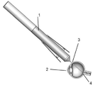
図1は、網膜下腔内に注射するために、眼に適用した装置を示す図である。装置1は、毛様体扁平部3で眼2内に挿入される。装置1の遠位末端は眼の後部表面に前進し、先端は網膜を通って挿入され、装置1は、十分な注入物質を注射し、網膜下腔4を作り出すように作動する。
FIG. 1 shows a device applied to the eye for injection into the subretinal space. The device 1 is inserted into the
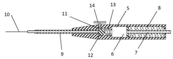
図2の図式に示されるように、本装置の一実施態様において、装置は、容器6およびバルブ機構を取り囲む本体部分5を備える。本体5の近位末端は、注入物質を吐出する力要素としての役割を果たすプランジャー7およびプランジャースプリング8を収納する。本体5の遠位末端は、中空軸9に取り付けられる。中空軸9の遠位末端は、中空カニューレ10に取り付けられる。本体5の中央部分は、変形可能な弁座11、球形バルブ密閉要素12、バルブスプリング13およびバルブアクチュエータ14を備えるバルブ機構を収納する。
As shown in the diagram of FIG. 2, in one embodiment of the device, the device comprises a
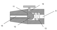
バルブ機構起動の断面図が、図3Aおよび図3Bに示される。図3Aにおいて、バルブ機構は閉位置にあることが示される。バルブスプリング13は、弁座11に対するバルブ密閉要素12に力を供給する。それによって、容器6から軸管腔15への流れを止めている。バルブアクチュエータ14は押し下げられていない位置にあり、弁座11の外側と接触しているが、弁座11に対していかなる力も与えていない。図3Bにおいて、バルブアクチュエータ14は押し下げられ、弁座11の変形をもたらしている。弁座11の変形は、容器6から、バルブ密閉要素12の周囲および軸管腔15内への流れを可能にする。
Sectional views of the valve mechanism activation are shown in FIGS. 3A and 3B. In FIG. 3A, the valve mechanism is shown to be in the closed position. The
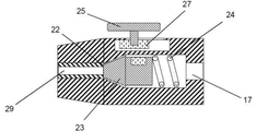
図4の図に示されるように、本装置の一実施態様において、装置は、容器17およびバルブ機構を取り囲む本体部分16を備える。本体16の近位末端は、注入物質を吐出する力要素としての役割を果たすプランジャー18およびプランジャースプリング19を収納する。本体16の遠位末端は、中空軸20に取り付けられる。中空軸20の遠位末端は、中空カニューレ21に取り付けられる。本体16の中央部分は、弁座22、バルブ密閉要素23、バルブスプリング24およびバルブアクチュエータ25を備えるバルブ機構を収納する。バルブ密閉要素23は、磁性または常磁性要素26を収納する。バルブアクチュエータは磁性要素27を含み、直線状の軌道に摺動可能に配置される。
As shown in the figure of FIG. 4, in one embodiment of the device, the device comprises a
バルブ機構起動の断面図が、図5Aおよび図5Bに示される。図5Aにおいて、バルブ機構は閉位置にあることが示される。バルブスプリング24は、弁座22に対するバルブ密閉要素23に力を供給する。それによって、容器17から軸管腔29への流れを止めている。バルブアクチュエータ25およびアクチュエータ磁性要素27は、遠位位置にある。図5Bにおいて、バルブアクチュエータ25は近位位置にあり、アクチュエータ磁性要素27は、磁性または常磁性要素26およびバルブ密閉要素23を、バルブスプリング24に対して近位に動かす力を与える。それによって、容器17から軸管腔29への流れを可能にする。
Sectional views of the valve mechanism activation are shown in FIGS. 5A and 5B. In FIG. 5A, the valve mechanism is shown to be in the closed position. The
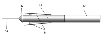
本装置の一実施態様の図が、図6に示される。装置は、近位筺体30、遠位筺体31、遠位筺体蓋32、二つの機械的作動レバー33および遠位カニューレ組立品34を備える。図7は、本装置の断面図を示す。遠位筺体32の中に、遠位カニューレ組立品34に対して遠位に、かつカートリッジ受け器組立品36に対して近位に取り付けられたバルブ組立品35があり、またカートリッジ組立品37がある。近位筺体30の中に、プランジャー組立品38がある。
A diagram of one embodiment of the device is shown in FIG. The device comprises a
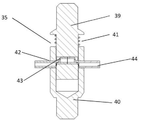
図7のバルブ機構の図が、図8Aおよび図8Bに示される。図8Aにおいて、バルブ組立品35は、通常は閉位置にある。当該バルブは、上部バルブ本体39、下部バルブ本体40およびバルブスプリング41を備える。これらのバルブ本体は、孔部42および43を通して合体している。弾性管44は、バルブ孔42および43を通して配置される。バルブスプリング41が下部バルブ本体を押す場合、孔42および43は、軸方向には整列せず、弾性管44は締め付けられて閉じる。これは、バルブの通常の閉位置を説明する。図8Bに示されるように、力を加えて、バルブ本体39および40をバルブスプリング41に対して共に押し付ける場合、バルブ孔42および43は整列する。それによって弾性管44の管腔45が開き、バルブを通って液体が流れることを可能にする。
Figures of the valve mechanism of FIG. 7 are shown in FIGS. 8A and 8B. In FIG. 8A, the
図9は、図6の装置の遠位内部要素の図を示す。遠位カニューレ組立品34は、先端46に小口径の注入管を備え、この注入管はより大口径の中間軸管47に結合している。次に、中間軸管47は、より大きな口径を持つ主軸管48に結合している。主軸管48の近位末端は、バルブ組立品の弾性管44の遠位末端に挿入される。バルブ組立品は、上部バルブ本体39、バルブスプリング41および下部バルブ本体40を備える。弾性管44は、バルブ本体39および40を通って挿入される。カートリッジ受け器36は、受け器本体49および受け器針50を備える。受け器針50の遠位末端は、バルブ組立品の弾性管44の近位末端に挿入される。受け器針の近位末端は、カートリッジ組立品の隔壁52を貫通するように斜角がつけられる。カートリッジ組立品37は、カートリッジ本体51、カートリッジ隔壁52、カートリッジ蓋53および動かすことができるカートリッジプランジャー54を備える。O-リング55はカートリッジプランジャーに取り付けられ、カートリッジ本体51の内部表面に対する摺動シールを与える。
FIG. 9 shows a diagram of the distal internal elements of the device of FIG. The
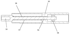
図10は、図6の装置の近位要素の図を示す。近位筺体30は、プランジャー組立品38を収納する。プランジャー組立品38は、プランジャー軸56、プランジャースプリング57およびプランジャー止58を備える。プランジャー軸56の遠位末端は、遠位末端孔に組み込まれ、カートリッジプランジャーと結合する。
FIG. 10 shows a diagram of the proximal elements of the device of FIG. The
図11は、動作速度を制御する制動機構に合体している図6の装置の、近位要素の別の実施態様の図を示す。近位筺体30は、プランジャー組立品38を収納する。プランジャー組立品38は、プランジャー軸56、プランジャースプリング57およびプランジャー止58を備える。プランジャー軸56の遠位末端は、遠位末端孔に組み込まれ、カートリッジプランジャーと結合する。プランジャー軸56の近位末端は、先細部分59と合体している。摩擦制動要素60は、制動要素60の先端がプランジャー軸56の先細部分59と可変接触するように、近位筺体30内に配置される。
FIG. 11 shows another embodiment of the proximal element of the device of FIG. 6 coupled with a braking mechanism that controls operating speed. The
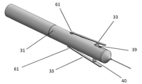
図12は、図6の装置の作動機構を示す。二つの作動レバー33は、遠位筺体に旋回軸61によって近位で取り付けられる。レバー33の遠位末端は、バルブ組立品本体39および40の先に係合する。レバー33が手動で押された場合、図8Bに示されるように、バルブ本体39および40は、組み合わさってバルブを開放する。
FIG. 12 shows the operating mechanism of the device of FIG. The two
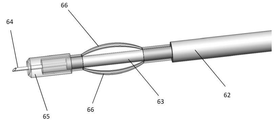
図13は、組織接点機構を備える装置の一実施態様の遠位末端を示す。遠位末端は、カニューレ組立品および組織接点組立品を備える。カニューレ組立品は近位主軸62を備え、その中には小口径中間軸63が結合している。細いゲージの注入管64は、中間軸63の末端に結合している。組織接点組立品は、中間軸63および注入管64の周囲に配置される。組織接点は、遠位弾性組織シール65および2軸圧縮要素66を備える。組織接点組立品は、遠位シール65を貫通する注入管64、および装置の縦軸から離れるように湾曲した、または曲げられた圧縮要素66を伴う作動位置にあることが示される。
FIG. 13 shows the distal end of an embodiment of a device comprising a tissue contact mechanism. The distal end comprises a cannula assembly and a tissue contact assembly. The cannula assembly includes a
本発明により、炎症、感染、黄斑変性、網膜変性、血管新生、増殖性硝子体網膜症、緑内障および浮腫を含む種々の眼疾患および症状の治療のために、様々な治療薬を眼に送達することができる。有用な薬物には以下が含まれるが、これらに限定されない。すなわち、デキサメタゾン、フルオシノロン、ロテプレドノール、ジフルプレドナート、フルオロメトロン、プレドニゾロン、メドリゾン、トリアムシノロン、ベタメタゾンおよびリメキソロンを含む副腎皮質ステロイドなどのステロイド;ブロムフェナク、ジクロフェナク、フルルビプロフェン、ケトロラクトロメタミンおよびネパフェナクを含むサリチル酸-、インドール酢酸-、アリール酢酸-、アリールプロピオン酸-およびエノール酸-誘導体などの非ステロイド性抗炎症薬;アジスロマイシン、バシトラシン、ベシフロキサシン、シプロフロキサシン、エリスロマイシン、ガチフロキサシン、ゲンタマイシン、レボフロキサシン、モキシフロキサシン、オフロキサシン、スルファセタミドおよびトブラマイシンを含む抗生物質;チロシンキナーゼ阻害剤、VEGFに対する抗体、VEGFに対する抗体フラグメント、VEGF結合融合タンパク質などのVEGF阻害剤;PDGFに対する抗体、PDGFに対する抗体フラグメント、PDGF結合融合タンパク質などのPDGF阻害剤;インフリキシマブ、エタネルセプト、アダリムマブ、セルトリズマブおよびゴリムマブを含むTNFαに対する抗体、TNFαに対する抗体フラグメントおよびTNF結合融合タンパク質などの抗TNFα剤;シロリムス、シロリムス類似体、エベロリムス、テムシロリムスおよびmTORキナーゼ阻害剤などのmTOR阻害剤;間葉系細胞(例えば間葉系幹細胞)または治療用化合物を産生するように遺伝子導入された細胞などの細胞;抗酸化剤、カルシニューリン阻害剤、NOS阻害剤、σ1修飾因子、AMPA拮抗薬、カルシウムチャネル遮断薬およびヒストン脱アセチル化酵素阻害薬などの神経保護薬;プロスタグランジン類似体、β遮断薬、α刺激薬および炭酸脱水酵素阻害剤などの降圧薬;スクアラミンなどのアミノステロール;H1受容体拮抗薬およびH2受容体拮抗薬などの抗ヒスタミン薬;治療用細胞;チロシンキナーゼ阻害剤ならびに遺伝子ベクター、プラスミドおよびsiRNAなどの核酸に基づく治療薬である。 INDUSTRIAL APPLICABILITY According to the present invention, various therapeutic agents are delivered to the eye for the treatment of various eye diseases and symptoms including inflammation, infection, macular degeneration, retinal degeneration, neovascularization, proliferative vitreoretinopathy, glaucoma and edema. be able to. Useful drugs include, but are not limited to: That is, steroids such as corticosteroids including dexamethasone, fluosinolone, roteprednol, diflupredonato, fluoromethron, prednisolone, medrizone, triamcinolone, betamethasone and limexolone; Non-steroidal anti-inflammatory agents such as salicylic acid-, indol acetate-, arylacetic acid-, arylpropionic acid-and enolic acid-derivatives; Antibiotics including moxyfloxacin, ofloxacin, sulfacetamide and tobramycin; Tyrosine kinase inhibitors, antibodies against VEGF, antibody fragments against VEGF, VEGF inhibitors such as VEGF binding fusion protein; antibodies against PDGF, antibody fragments against PDGF, PDGF binding PDGF inhibitors such as fusion proteins; antibodies against TNFα including infliximab, etanercept, adalimumab, sertrizumab and golimumab, antibody fragments against TNFα and anti-TNFα agents such as TNF-binding fusion proteins; MTOR inhibitors such as inhibitors; cells such as mesenchymal cells (eg, mesenchymal stem cells) or cells genetically introduced to produce therapeutic compounds; antioxidants, calcinulin inhibitors, NOS inhibitors, σ1 Neuroprotective agents such as modifiers, AMPA antagonists, calcium channel blockers and histone deacetylase inhibitors; antihypertensive agents such as prostaglandin analogs, β blockers, alpha stimulants and carbonate dehydration enzyme inhibitors; squalamine Aminosterols such as; antihistamines such as H1 receptor antagonists and H2 receptor antagonists; therapeutic cells; tyrosine kinase inhibitors and nucleic acid-based therapeutic agents such as gene vectors, plasmids and siRNAs.
本発明は、以下の実施例に言及しながら説明するが、これらの実施例は説明に役立てることのみを目的としており、請求項に係る発明を限定するものとして解釈されるべきものではない。 The present invention will be described with reference to the following examples, but these examples are for the purpose of providing explanation only and should not be construed as limiting the claimed invention.
〔注射装置の一実施態様の製造〕
図2に示される装置と同様の一実施態様に係る装置を製造した。長さ14.75 mmのバルブ本体は、デュロメータ50ショアA(Nusil社、品番MED-4950)のシリコーンゴムから成形した。このバルブ本体は、バルブ密閉要素として作動する直径3.175 mmのステンレス鋼球形ボールならびに直径0.3 mmの針金から作製された直径3.175 mmおよび長さ8.26 mmのバルブ圧縮スプリングが入る大きさに成形した、直径3.43 mmおよび奥行き6.5 mmの近位バルブチャンバーを備えた。直径1.91 mmおよび奥行き2.35 mmの弁座をチャンバーの遠位に組み込み、前記ボールがバルブ密閉要素として作動するように構成したバルブ本体を、バルブスプリングにより弁座に対して押し込んだ。成形したバルブ本体の近位末端に、直径9.25 mmおよび厚さ1.25 mmの圧縮フランジを組み込んだ。バルブ本体の遠位末端には、本体中に圧入された23ゲージの管を受け入れる管腔を配置した。
[Manufacturing of One Embodiment of Injection Device]
An apparatus according to an embodiment similar to the apparatus shown in FIG. 2 was manufactured. The 14.75 mm long valve body was molded from silicone rubber with
中空管状軸は、内径0.33 mm、外径0.64 mmおよび長さ30 mmの23ゲージの細長い管から作製した。内径0.15 mmおよび外径0.30 mmの30ゲージの細長い管の小断片を、23ゲージ管の先端内部に接着によって結合させ、23ゲージ軸と遠位カニューレとの間のスペーサーとして作用するようにした。30ゲージ軸部分は、露出長を8.9 mmとした。遠位カニューレは、内径0.09 mmおよび外径0.13 mmのポリイミド管(Microlumen社、品番039-I)から作製し、30ゲージ軸管の内部に接着によって結合させた。露出長は6.35 mmとした。遠位軸およびカニューレ組立品は、バルブ本体の遠位末端中に挿入し、また、バルブ密閉要素およびバルブスプリングは、バルブ本体の近位末端中に組み立てた。それによってバルブ組立品が形成された。 The hollow tubular shaft was made from a 23 gauge elongated tube with an inner diameter of 0.33 mm, an outer diameter of 0.64 mm and a length of 30 mm. A small piece of a 30-gauge elongated tube with an inner diameter of 0.15 mm and an outer diameter of 0.30 mm was glued together inside the tip of the 23-gauge tube to act as a spacer between the 23-gauge shaft and the distal cannula. The exposed length of the 30 gauge shaft was 8.9 mm. The distal cannula was made from a polyimide tube with an inner diameter of 0.09 mm and an outer diameter of 0.13 mm (Microlumen, stock number 039-I) and bonded to the inside of a 30 gauge shaft tube. The exposed length was 6.35 mm. The distal shaft and cannula assembly were inserted into the distal end of the valve body, and the valve sealing element and valve spring were assembled into the proximal end of the valve body. This formed the valve assembly.
容器は、0.5 mLのシリンジ本体(テルモ、U-100型)の遠位末端を切断することにより作製し、完成長を40 mmとした。シリンジ本体の指当ては小さくし、バルブ本体フランジと一致させるため、直径8.45 mmの遠位円形フランジ部分を作成した。シリンジ本体は、内径3.63 mmおよび外径5.35 mmとした。シリンジ本体の近位末端には、8-32 UNCのねじ山を取り付けた。 The container was made by cutting the distal end of a 0.5 mL syringe body (Terumo, U-100 type) to a finished length of 40 mm. The finger rest of the syringe body was made small, and a distal circular flange part with a diameter of 8.45 mm was created to match the flange of the valve body. The syringe body had an inner diameter of 3.63 mm and an outer diameter of 5.35 mm. A 8-32 UNC thread was attached to the proximal end of the syringe body.
プランジャーは、内径0.9 mmおよび外径1.8 mmならびに長さ72 mmのステンレス鋼管から作製した。内径1.7 mmおよび外径3.25 mmの鋼ワッシャー2枚を、ワッシャー間に1.31 mmの間隙をおいて、プランジャーの遠位末端に圧入した。内径1.07 mmおよび横断面1.27 mmのシリコーンO-リングを、容器本体の内部でプランジャーシールとしての役割を果たすように、ワッシャー間に取り付けた。外径3.35 mm、長さ38 mmおよび線径0.3 mmのプランジャースプリングを、ワッシャーの近位にあるプランジャー軸のすべてにわたり取り付けた。プランジャー末端キャップは、ナイロン8-32穴付きボルトから作製した。らせん軸は、直径1.9 mmにドリルで孔を開け、キャップ部分は直径5 mmに機械加工した。末端キャップは、プランジャースプリングの近位にあるプランジャーの上に取り付けた。プランジャーの近位末端は、ポリエーテルエーテルケトン(PEEK)スペーサーを持つルアーチェックバルブ(Qosina社、品番80088)に取り付け、チェックバルブ遠位管継手中に圧入するように、またプランジャー軸を受け入れるように機械加工した。それによって、チェックバルブとプランジャーとの間に、液漏れしない接続を形成した。組み立てられたプランジャーは容器内に挿入し、また、末端キャップは容器の近位末端内にねじ込み、それによって容器組立品が形成された。 The plunger was made from stainless steel pipe with an inner diameter of 0.9 mm and an outer diameter of 1.8 mm and a length of 72 mm. Two steel washers with an inner diameter of 1.7 mm and an outer diameter of 3.25 mm were press-fitted into the distal end of the plunger with a gap of 1.31 mm between the washers. A silicone O-ring with an inner diameter of 1.07 mm and a cross section of 1.27 mm was attached between the washers to act as a plunger seal inside the vessel body. Plunger springs with an outer diameter of 3.35 mm, a length of 38 mm and a wire diameter of 0.3 mm were attached over all of the plunger shafts proximal to the washer. The plunger end cap was made from nylon 8-32 hole bolts. The spiral shaft was drilled to a diameter of 1.9 mm and the cap was machined to a diameter of 5 mm. The end cap was mounted on the plunger located proximal to the plunger spring. The proximal end of the plunger is attached to a luer check valve (Qosina, part number 80088) with a polyetheretherketone (PEEK) spacer so that it is press-fitted into the check valve distal fitting and also accepts the plunger shaft. Machined as. As a result, a leak-proof connection was formed between the check valve and the plunger. The assembled plunger was inserted into the container and the end cap was screwed into the proximal end of the container, thereby forming the container assembly.
作動ボタンはPEEKから作製した。ボタンは、指ボタン部分および軸部分を備えた。指ボタン部分は、直径9.7 mmおよび厚さ2.1 mmとした。軸部分は長さ8.8 mmであり、その先端は直径1.6 mmであった。装置本体は、二つの部分ともアクリロニトリル・ブタジエン・スチレン(ABS)から作製した。遠位部分は、組み立てられたバルブ本体を受け入れるように構成し、また近位末端は、容器組立品を受け入れるように構成した。当該二つの部分は、螺合して組み立てるように構成した。装置本体の長軸に対して垂直な先端部分にドリルで孔を開け、作動ボタンの軸を受けるようにした。孔は、作動ボタン軸がバルブ本体と、弁座の近位端で接触するように設置した。作動ボタンの押し込みにより、バルブ本体が押し込まれ、弁座が変形した。 The actuation button was made from PEEK. The button provided a finger button portion and a shaft portion. The finger button part has a diameter of 9.7 mm and a thickness of 2.1 mm. The shaft was 8.8 mm long and its tip was 1.6 mm in diameter. The body of the device was made from acrylonitrile butadiene styrene (ABS) in both parts. The distal part was configured to accept the assembled valve body and the proximal end was configured to receive the container assembly. The two parts were configured to be screwed together. A hole was drilled in the tip part perpendicular to the long axis of the main body of the device to receive the axis of the operation button. The holes were installed so that the actuating button shaft was in contact with the valve body at the proximal end of the valve seat. By pushing the operation button, the valve body was pushed in and the valve seat was deformed.
中央ワッシャーは、内径2.36 mm、外径8.95 mmおよび厚さ0.88 mmのポリテトラフルオロエチレン(PTFE)から作製した。当該ワッシャーは、バルブフランジと容器フランジとの間を密閉し、また、弁座に対するバルブ密閉要素の密閉力を与えるバルブスプリングを圧縮する役目を果たす。バルブ組立品は装置本体の遠位部分に挿入し、容器組立品はバルブ本体の近位部分に挿入し、また中央ワッシャーは、容器フランジとバルブフランジとの間に存するように、近位部分に挿入した。装置本体の当該二つの部分は螺合した。作動ボタンは遠位部分の孔に挿入し、装置の組み立てを完了した。 The central washer was made from polytetrafluoroethylene (PTFE) with an inner diameter of 2.36 mm, an outer diameter of 8.95 mm and a thickness of 0.88 mm. The washer serves to seal between the valve flange and the container flange and to compress the valve spring that provides the sealing force of the valve sealing element to the valve seat. The valve assembly is inserted into the distal part of the device body, the container assembly is inserted into the proximal part of the valve body, and the central washer is in the proximal part so that it lies between the vessel flange and the valve flange. I inserted it. The two parts of the device body were screwed together. The actuation button was inserted into the hole in the distal part to complete the assembly of the device.
〔注射装置の検査〕
実施例1に記載の装置を作製した。注入物質として脱イオン水を1 mLシリンジに吸い上げ、このシリンジを、プランジャーチェックバルブのルアー取り付け具に取り付けた。約0.3 mLの水を容器に充填し、プランジャーを近位に後退させて、プランジャースプリングを圧縮した。それによって、装置容器の中の注入物質に力を与えた。注入物質の、遠位カニューレからの流出はなかった。作動ボタンが押し下げられると、遠位カニューレからの水の流出が見られた。作動ボタンを自由にすると、液流が止まった。この動作を繰り返しても、同じ結果が得られた。
[Inspection of injection device]
The apparatus according to Example 1 was produced. Deionized water was sucked up into a 1 mL syringe as an injection substance, and this syringe was attached to the luer fitting of the plunger check valve. The container was filled with about 0.3 mL of water and the plunger was retracted proximally to compress the plunger spring. This gave power to the injectable material in the device container. There was no outflow of injectable material from the distal cannula. When the actuation button was pressed down, an outflow of water from the distal cannula was seen. When the operation button was released, the liquid flow stopped. The same result was obtained by repeating this operation.
〔眼における注射装置の検査〕
実施例1に記載の装置を作製した。網膜下注射を目的として本装置を使用するため、ブタ死体眼を準備した。処置は、視覚化を容易にするために実体顕微鏡下で行った。死体眼の網膜に接近するため、角膜縁で角膜を完全に除去した。実のレンズを、レンズから小帯線維を切り取ることにより注意深く切除した後、眼球からレンズを取り除いた。硝子体を、網膜を後ろに残したまま、ひとまとめに除去した。本装置には、0.1%フルオレセイン溶液を満たし、プランジャーチェックバルブに取り付けた1 mLシリンジを使用して、0.2 mLのフルオレセイン溶液を充填した。遠位カニューレを、網膜組織を通して注意深く挿入し、前進させた。カニューレは、脈絡膜表面を横切って曲がり、組織に沿って短い距離を横切った。
[Inspection of injection device in the eye]
The apparatus according to Example 1 was produced. A porcine carcass eye was prepared for use with this device for subretinal injection. The procedure was performed under a stereomicroscope to facilitate visualization. The cornea was completely removed at the corneal margin to approach the retina of the cadaveric eye. The real lens was carefully excised by cutting the zonule fibers from the lens and then the lens was removed from the eyeball. The vitreous was removed in bulk, leaving the retina behind. The device was filled with 0.1% fluorescein solution and 0.2 mL of fluorescein solution using a 1 mL syringe attached to a plunger check valve. The distal cannula was carefully inserted through the retinal tissue and advanced. The cannula bent across the choroidal surface and crossed a short distance along the tissue.
作動ボタンを約1.5秒間押し下げると、その間に、フルオレセイン溶液が網膜下に空隙を作り、その空隙を満たすのが見られた。注入時間後、作動ボタンを自由にすると、カニューレからの流れは止まり、それからカニューレを引き抜いた。 When the actuation button was pressed down for about 1.5 seconds, fluorescein solution was seen to create a void under the retina and fill the void. After the injection time, when the actuation button was released, the flow from the cannula stopped and then the cannula was pulled out.
〔注射装置の一実施態様の製造〕
図6および7に示された装置と同類である実施態様の装置を作製した。本装置は、二つの要素で構成された円筒形の筺体、および遠位カニューレ組立品を保持する筺体キャップを備えた。遠位筺体要素は、注入物質を含むカートリッジを受け入れる大きさの内部空洞を、近位末端に備えた。遠位筺体の中に、カートリッジの受け器本体およびバルブ本体から成る組立品を入れた。遠位筺体の外側に、バルブを作動させるために、180度離れて二つの機械的作動レバーを取り付けた。遠位筺体は、外径9.4 mm、内径8.7 mmおよび長さ56.5 mmの真鍮管から作製した。近位筺体要素には、液体充填カートリッジの上から適合する大きさの開放された近位末端、およびカートリッジ内の摺動シールの中に適合する大きさのスプリングを装着したプランジャー組立品を備え、カートリッジの内容物を吐出する力を与えた。近位筺体要素は、外径10.3 mm、内径9.5 mmおよび長さ62 mmの真鍮管から作製され、遠位筺体要素と摺動可能に結合する大きさとした。
[Manufacturing of One Embodiment of Injection Device]
An apparatus of an embodiment similar to the apparatus shown in FIGS. 6 and 7 was made. The device was equipped with a two-element cylindrical housing and a housing cap to hold the distal cannula assembly. The distal housing element provided a proximal end with an internal cavity sized to accommodate a cartridge containing the injectable material. Inside the distal housing was an assembly consisting of a cartridge receiver body and a valve body. On the outside of the distal housing, two mechanical actuating levers were mounted 180 degrees apart to actuate the valve. The distal housing was made from a brass tube with an outer diameter of 9.4 mm, an inner diameter of 8.7 mm and a length of 56.5 mm. The proximal housing element comprises an open proximal end sized to fit from above the liquid-filled cartridge, and a plunger assembly fitted with a sized spring fitted within the sliding seal inside the cartridge. , Giving the force to eject the contents of the cartridge. The proximal housing element was made from a brass tube with an outer diameter of 10.3 mm, an inner diameter of 9.5 mm and a length of 62 mm, and was sized to slidably connect to the distal housing element.
容器およびバルブ組立品は、遠位筺体本体の中に適合するように作製した。容器はポリエチレンから作製し、閉鎖された遠位末端および開放された近位末端を持たせた。開放された近位末端は、カートリッジの遠位末端をわずかに締まり嵌めしながら収容する大きさとした。容器軸にドリルで孔を開け、23ゲージの細長い管の短い部分を容器内に圧入した。細長い管は容器内で近位に伸び、管の近位末端には斜角がつけられ、カートリッジが筺体内に挿入される場合は、カートリッジの末端シールを貫通することを可能とした。 The container and valve assemblies were made to fit within the body of the distal housing. The container was made of polyethylene and had a closed distal end and an open proximal end. The open proximal end was sized to accommodate the distal end of the cartridge with a slight tight fit. A hole was drilled in the container shaft and a short portion of a 23 gauge elongated tube was press-fitted into the container. The elongated tube extended proximally within the container and the proximal end of the tube was beveled to allow the cartridge to penetrate the end seal of the cartridge when inserted into the housing.
二つの要素で構成されたバルブ本体は、アセタール重合体から作製した。バルブ本体の第一の要素は、一端に、第二の要素にある容器孔内に適合する大きさの円筒形の突起を備えた。ステンレス鋼圧縮スプリングは、第一の要素にある円筒形の突起の周囲に適合するように巻かれ、第二の要素に対して力を与えた。ドリルで、両方の要素に、要素の軸に対して90度で孔を開けると、スプリングが圧縮されて前記突起が容器内に摺動する場合、孔は同軸状に整列し、そのため孔が開き、また、スプリングが、当該二つの要素を別々に押す場合、孔軸はもはや整列せず、バルブは閉じた。内径0.30 mmおよび外径0.64 mmのシリコーン弾性管の一部を、孔を通して挿入した。圧縮されていない状態では、シリコーン管は、閉鎖した貫通孔により締め付けられて閉じた。このような方法で、通常閉じたバルブが作り出された。バルブ要素が一緒に押し込まれた場合、前記孔の開放は、シリコーン管の締め付けを解放し、バルブを通って液体が流れることを可能にした。流量は、二つのバルブ要素の押し込み量により制御することができた。容器の細長い管の遠位末端を、シリコーンバルブ管の近位末端に結合させた。バルブ本体要素の外端は、円筒形の突起を備えた。機械的作動レバーは円筒形の突起を圧迫し、バルブ機構が作動するように構成した。 The valve body composed of two elements was made from an acetal polymer. The first element of the valve body was provided at one end with a cylindrical protrusion sized to fit into the vessel hole in the second element. The stainless steel compression spring was wound to fit around the cylindrical protrusion on the first element and exerted a force on the second element. Drilling holes in both elements at 90 degrees to the axis of the element will cause the holes to align coaxially when the spring is compressed and the protrusion slides into the vessel, thus opening the holes. Also, when the spring pushes the two elements separately, the hole shafts are no longer aligned and the valve closes. A part of a silicone elastic tube with an inner diameter of 0.30 mm and an outer diameter of 0.64 mm was inserted through the hole. In the uncompressed state, the silicone tube was tightened and closed by a closed through hole. In this way, normally closed valves were created. When the valve elements were pushed together, the opening of the holes released the tightening of the silicone tubing and allowed the liquid to flow through the valve. The flow rate could be controlled by the amount of pushing of the two valve elements. The distal end of the elongated tube of the container was attached to the proximal end of the silicone valve tube. The outer end of the valve body element was provided with a cylindrical protrusion. The mechanical actuating lever was configured to compress the cylindrical protrusion and actuate the valve mechanism.
遠位カニューレ組立品を、筺体キャップ内に圧入することのできる長さの23ゲージの細長い管で構成した。23ゲージ管を、キャップから24 mmの長さで遠位に、またキャップから3 mm の長さで近位に伸ばした。30ゲージの細長い管部品は、23ゲージの細長い管の遠位IDに接合させ、23ゲージ管端を越えて、4 mm伸ばした。内径0.01 mmおよび外径0.13 mmのポリイミド管部品は、30ゲージ管の遠位末端に接合させ、端から遠位に5 mm伸ばした。23ゲージ管の近位末端は、シリコーンバルブ管の遠位末端に接合させた。遠位カニューレおよび筐体キャップ、バルブ本体ならびに容器本体を備える組立品は、遠位筐体に挿入した。二つの機械的作動レバーは、外径10.3 mm、内径9.5 mmおよび長さ35 mmの真鍮管の単体から機械加工した。ここで、管の近位末端は円形のままであり、遠位筐体への取り付けを可能にした。2本の幅広の溝を、管の遠位末端から管長の大部分に沿って切り、真鍮の2本の軸長がレバーアームとしての役割を果たすようにした。レバー本体は遠位筐体上を摺動し、2本のレバーアームが、バルブ本体の円筒形の突起上に位置するような場所に結合させた。 The distal cannula assembly consisted of a 23-gauge elongated tube long enough to be press-fitted into the housing cap. A 23-gauge tube was extended distally 24 mm from the cap and proximally 3 mm from the cap. A 30-gauge elongated tube component was joined to the distal ID of a 23-gauge elongated tube and extended 4 mm beyond the end of the 23-gauge tube. Polyimide tube components with an inner diameter of 0.01 mm and an outer diameter of 0.13 mm were joined to the distal end of a 30 gauge tube and extended 5 mm distal to the end. The proximal end of the 23 gauge tube was joined to the distal end of the silicone valve tube. The assembly with the distal cannula and housing cap, valve body and container body was inserted into the distal housing. The two mechanical actuating levers were machined from a single brass tube with an outer diameter of 10.3 mm, an inner diameter of 9.5 mm and a length of 35 mm. Here, the proximal end of the tube remained circular, allowing attachment to the distal enclosure. Two wide grooves were cut from the distal end of the tube along most of the tube length so that the two brass shaft lengths acted as lever arms. The lever body slid over the distal housing and the two lever arms were coupled where they were located on the cylindrical protrusions of the valve body.
近位筐体には、プランジャー軸およびスプリング組立品が含まれた。プランジャー軸は、ポリエーテルエーテルケトン(PEEK)から作製され、遠位末端に孔を、また近位末端に直径が小さくなった軸を備えた。プランジャー軸の近位10 mmには、ねじ山を付けた。プランジャー遠位末端は、カートリッジ摺動シールの近位末端の上に適合する孔を持つ、液体で満たしたカートリッジの管腔内に適合する大きさとし、スプリングからの力が摺動シールに伝達されるようにした。ステンレス鋼圧縮スプリングは、プランジャーの近位末端上を摺動した。スプリング止は、近位装置筐体の内部に取り付けた。スプリング止は、プランジャー軸の近位末端に滑り嵌めするように、孔を組み込んだ。プランジャー軸は、スプリング止を通して取り付け、またナイロンナットを、軸の近位末端上に装着した。このような方法でプランジャー軸が近位に押し進められ、スプリングを圧縮し、カートリッジの内容物を吐出する力を与えた。 The proximal enclosure contained a plunger shaft and spring assembly. The plunger shaft was made from polyetheretherketone (PEEK) and had a pore at the distal end and a reduced diameter shaft at the proximal end. A thread was added 10 mm proximal to the plunger shaft. The distal end of the plunger is sized to fit within the lumen of a liquid-filled cartridge with a matching hole above the proximal end of the cartridge sliding seal, and the force from the spring is transmitted to the sliding seal. It was to so. The stainless steel compression spring slid over the proximal end of the plunger. The spring stop was mounted inside the proximal device housing. The spring stop incorporates a hole so that it slides into the proximal end of the plunger shaft. The plunger shaft was mounted through a spring stop and a nylon nut was mounted on the proximal end of the shaft. In this way, the plunger shaft was pushed proximally, compressing the spring and giving it a force to eject the contents of the cartridge.
容器液体カートリッジ組立品を作製した。カートリッジ本体は、8 mmの冠部直径を持つ、標準ガラスの1.8 mL医薬品グレードカートリッジで構成された。遠位シールは、デュロメータ10ショアAを持つシリコーンエラストマーから作製した。当該シールは、8 mm丸パンチを用いて、シートから打ち抜いた。シールは冠部に取り付け、また一般的な8 mmアルミニウムシールを端上に取り付けて、圧縮工具を用いて圧着した。摺動シール本体は、PEEKから作製した。当該シールの遠位末端は、ガラスカートリッジの内部曲率に近似するように機械加工し、デッドボリュームを限定した。本体周囲に溝を切り込み、シリコーンO-リングをその溝に取り付けて、本体とガラスカートリッジとの間に、密閉力を与えた。本体の近位末端は、ねじ山を付けた長さ5 mmの突起を備えた。取り外し可能な手動のプランジャーは、一般的なポリプロピレンシリンジプランジャーから作製した。プランジャーの先端は切り取り、遠位末端には、カートリッジ中の摺動シール本体に取り付けられるように、ねじ山を付けた。注入シリンジは、一般的な3 mLポリプロピレンルアーロックシリンジ筒および針組立品から作製した。針組立品は、ルアーハブに挿入された25ゲージの細長い針を備え、針の近位末端が、ルアーハブから9.5 mm近位に伸びるようにした。針の近位末端には斜角をつけ、針がカートリッジの遠位シールを貫通するようにした。針組立品は、シリンジ筒に取り付けた。
A container liquid cartridge assembly was made. The cartridge body consisted of a standard glass 1.8 mL pharmaceutical grade cartridge with a crown diameter of 8 mm. The distal seal was made from a silicone elastomer with a
使用にあたって、カートリッジはシリンジ筒に挿入し、プランジャーを、カートリッジ摺動シールに取り付けた。針を液体充填バイアルに挿入し、プランジャーおよびシール近位に引き寄せ、液体をカートリッジ内に取り出した。シリンジ本体およびプランジャーは、カートリッジから取り除いた。カートリッジは、受け器に固定されるまで、遠位装置筐体に挿入した。近位装置筐体を遠位筐体に取り付け、プランジャー軸の遠位末端をカートリッジ摺動シールと係合させ、またプランジャー軸でプランジャースプリングを圧縮した。バルブが閉じていれば、液体は流れなかった。作動レバーを手動で押して、バルブ本体部分を共に圧縮し、シリコーン管を開放すると、流れが装置を通り、末端ポリイミド管から流れ出るようになった。アクチュエータへの圧力を増すと、シリコーン管の管腔の開きが大きくなり、それによって、装置を通る流れが増加した。
In use, the cartridge was inserted into the syringe barrel and the plunger was attached to the cartridge sliding seal. The needle was inserted into a liquid-filled vial and pulled proximal to the plunger and seal to remove the liquid into the cartridge. The syringe body and plunger were removed from the cartridge. The cartridge was inserted into the distal device enclosure until it was secured to the receiver. The proximal device housing was attached to the distal housing, the distal end of the plunger shaft was engaged with the cartridge sliding seal, and the plunger spring was compressed by the plunger shaft. If the valve was closed, no liquid would flow. When the actuating lever was manually pushed to compress the valve body together and open the silicone tube, the flow passed through the device and flowed out of the terminal polyimide tube. Increasing the pressure on the actuator increased the luminal opening of the silicone tubing, which increased the flow through the device.
Claims (16)
カニューレを通して送達される注入物質のための容器;
注入物質に注入力を与える力要素を有するプランジャー;
容器とカニューレとの間の流路に配置されたバルブ;および、
バルブの外側にある、バルブに対するバルブ作動機構であって、細長い本体に取り付けられているバルブ作動機構;
を備える眼科用注射装置であって、
使用中、バルブが閉位置にあるとき、注入力が注入物質に加えられ、
バルブ作動機構の作動はバルブを通る流路を開放し、バルブ作動機構の漸進的な作動は注入流量を増加させる、
眼科用注射装置。 An elongated body with a hollow cannula fixed to the distal end of the body;
Container for injectable material delivered through the cannula;
Plunger with a force element that gives injection input to the injected substance;
Valves located in the flow path between the vessel and the cannula;
A valve actuation mechanism for the valve on the outside of the valve, which is attached to an elongated body;
It is an ophthalmic injection device equipped with
During use, when the valve is in the closed position, the injection input is applied to the injection material,
The actuation of the valve actuating mechanism opens the flow path through the valve, and the gradual actuation of the valve actuating mechanism increases the injection flow rate.
Ophthalmic injection device.
弾性的に変形可能な材料または材料の組み合わせを備える流路;および、
圧縮力を加えてバルブ内の流路を閉鎖する、流路の外側にある機構;
を備え、
バルブ作動機構による圧縮力の軽減は、閉鎖または部分的に閉鎖された形状から、流れ抵抗が低下した形状に流路の弾性を回復させる、
請求項1に記載の眼科用注射装置。 The valve
Channels with elastically deformable materials or combinations of materials; and
A mechanism outside the flow path that applies compressive force to close the flow path inside the valve;
With
The reduction of compressive force by the valve actuating mechanism restores the elasticity of the flow path from a closed or partially closed shape to a shape with reduced flow resistance.
The ophthalmic injection device according to claim 1.
内部バルブスプリング;
密閉要素;および、
弁座;
を備え、
密閉要素は、バルブスプリングによる密閉力の下で弁座に対して押し付けられ、バルブ作動機構によるバルブに対する外力は、弁座を変形させて流路を形成する、
請求項1に記載の眼科用注射装置。 The valve
Internal valve spring;
Sealing element; and
valve seat;
With
The sealing element is pressed against the valve seat under the sealing force of the valve spring, and the external force of the valve actuating mechanism against the valve deforms the valve seat to form a flow path.
The ophthalmic injection device according to claim 1.
内部バルブスプリング;
密閉要素;および、
弁座;
を備え、
密閉要素は、バルブスプリングによる密閉力の下で弁座に対して押し付けられ、少なくとも一つの密閉要素および弁座は磁性体または常磁性体であり、前記作動機構は、移動した場合、密閉要素と弁座との間の流路を開放する磁石を備える、
請求項1に記載の眼科用注射装置。 The valve
Internal valve spring;
Sealing element; and
valve seat;
With
The sealing element is pressed against the valve seat under the sealing force of the valve spring, at least one sealing element and the valve seat are magnetic or paramagnetic, and the actuating mechanism, when moved, with the sealing element. Equipped with a magnet that opens the flow path to and from the valve seat,
The ophthalmic injection device according to claim 1.
The ophthalmic injection device according to claim 5 or 6, wherein the valve seat is an asymmetric valve seat configured to include a groove or form a flow path.
Applications Claiming Priority (3)
| Application Number | Priority Date | Filing Date | Title |
|---|---|---|---|
| US201562220165P | 2015-09-17 | 2015-09-17 | |
| US62/220,165 | 2015-09-17 | ||
| PCT/EP2016/072024 WO2017046358A1 (en) | 2015-09-17 | 2016-09-16 | Ophthalmic injection device |
Publications (3)
| Publication Number | Publication Date |
|---|---|
| JP2018528835A JP2018528835A (en) | 2018-10-04 |
| JP2018528835A5 JP2018528835A5 (en) | 2019-10-24 |
| JP6920002B2 true JP6920002B2 (en) | 2021-08-18 |
Family
ID=56936430
Family Applications (1)
| Application Number | Title | Priority Date | Filing Date |
|---|---|---|---|
| JP2018513827A Active JP6920002B2 (en) | 2015-09-17 | 2016-09-16 | Ophthalmic injection device |
Country Status (7)
| Country | Link |
|---|---|
| US (1) | US11154420B2 (en) |
| EP (1) | EP3349826B1 (en) |
| JP (1) | JP6920002B2 (en) |
| ES (1) | ES2954983T3 (en) |
| GB (1) | GB2543645B (en) |
| PL (1) | PL3349826T3 (en) |
| WO (1) | WO2017046358A1 (en) |
Families Citing this family (22)
| Publication number | Priority date | Publication date | Assignee | Title |
|---|---|---|---|---|
| CA2762536C (en) | 2009-05-18 | 2019-05-21 | Dose Medical Corporation | Drug eluting ocular implant |
| US10206813B2 (en) | 2009-05-18 | 2019-02-19 | Dose Medical Corporation | Implants with controlled drug delivery features and methods of using same |
| US12478503B2 (en) | 2009-05-18 | 2025-11-25 | Glaukos Corporation | Implants with controlled drug delivery features and methods of using same |
| EP2654715B1 (en) | 2010-11-24 | 2017-01-25 | Dose Medical Corporation | Drug eluting ocular implant |
| JP6465490B2 (en) | 2012-03-26 | 2019-02-06 | グローコス コーポレーション | Implant delivery device |
| WO2017040853A1 (en) | 2015-09-02 | 2017-03-09 | Glaukos Corporation | Drug delivery implants with bi-directional delivery capacity |
| US11974945B2 (en) | 2017-08-31 | 2024-05-07 | Aperture In Motion, LLC | Devices and methods for novel retinal irradiance distribution modification to improve and restore vision without producing corneal vitrification |
| US20190060056A1 (en) * | 2017-08-31 | 2019-02-28 | Olivia Serdarevic | Devices and Methods for Novel Retinal Irradiance Distribution Modification to Improve and Restore Vision |
| WO2019070385A2 (en) | 2017-10-06 | 2019-04-11 | Glaukos Corporation | Systems and methods for delivering multiple ocular implants |
| US11096779B2 (en) * | 2018-12-19 | 2021-08-24 | Alcon Inc. | IOL injector having a spring-assisted IOL delivery mechanism |
| US11439500B2 (en) * | 2018-12-20 | 2022-09-13 | Alcon Inc. | IOL injector with automatic driver or assisted manual drive force |
| WO2020161342A1 (en) | 2019-02-08 | 2020-08-13 | Curevac Ag | Coding rna administered into the suprachoroidal space in the treatment of ophtalmic diseases |
| EP3946467A1 (en) | 2019-04-03 | 2022-02-09 | REGENXBIO Inc. | Gene therapy for eye pathologies |
| KR20250051157A (en) | 2019-06-05 | 2025-04-16 | 리제너론 파아마슈티컬스, 인크. | Devices and methods for precision dose delivery |
| JP7337967B2 (en) * | 2019-07-02 | 2023-09-04 | 北京▲華▼▲視▼▲諾▼▲維▼医▲療▼科技有限公司 | Reagent holder, detection device assembly, aqueous humor collection device and aqueous humor collection method |
| US20210361477A1 (en) * | 2020-05-11 | 2021-11-25 | Glaukos Corporation | Delivery of fluid to ophthalmic passages |
| DE102020115346A1 (en) | 2020-06-09 | 2021-12-09 | Carl Zeiss Meditec Ag | Controlled injection between two layers of tissue in the human eye |
| KR20230083287A (en) | 2020-10-07 | 2023-06-09 | 리젠엑스바이오 인크. | Gene therapy for ocular manifestations of CLN2 disease |
| IT202100027785A1 (en) * | 2021-10-29 | 2023-04-29 | Efg S R L | SYRINGE WITH SPRING |
| USD1037439S1 (en) | 2022-01-17 | 2024-07-30 | EyePoint Pharamaceuticals, Inc. | Ocular injector |
| EP4507741A1 (en) | 2022-04-14 | 2025-02-19 | RegenxBio Inc. | Gene therapy for treating an ocular disease |
| US20260034250A1 (en) | 2022-09-30 | 2026-02-05 | Regenxbio Inc. | Treatment of ocular diseases with recombinant viral vectors encoding anti-vegf fab |
Family Cites Families (48)
| Publication number | Priority date | Publication date | Assignee | Title |
|---|---|---|---|---|
| US78006A (en) * | 1868-05-19 | Improved gas apparatus | ||
| US1641976A (en) * | 1926-08-21 | 1927-09-13 | Antoine A Laurent | Hypodermic syringe |
| US3890971A (en) | 1973-10-23 | 1975-06-24 | Thomas A Leeson | Safety syringe |
| US5236424A (en) | 1992-06-05 | 1993-08-17 | Cardiac Pathways Corporation | Catheter with retractable cannula for delivering a plurality of chemicals |
| US5295972A (en) | 1992-08-04 | 1994-03-22 | Metatech Corporation | Hypodermic syringe with protective cap |
| US5250031A (en) | 1992-12-14 | 1993-10-05 | The George Washington University | Locking needle cover |
| US5540664A (en) | 1993-05-27 | 1996-07-30 | Washington Biotech Corporation | Reloadable automatic or manual emergency injection system |
| US5358489A (en) | 1993-05-27 | 1994-10-25 | Washington Biotech Corporation | Reloadable automatic or manual emergency injection system |
| GB9412301D0 (en) | 1994-06-17 | 1994-08-10 | Safe T Ltd | Hollow-needle drugs etc applicators |
| DE69505407T2 (en) | 1994-08-24 | 1999-05-27 | Westinghouse Electric Corp., Pittsburgh, Pa. | GAS TURBINE BLADE WITH COOLED PLATFORM |
| US6916000B2 (en) | 1998-07-02 | 2005-07-12 | Jeffrey N. Weiss | Apparatus and method for cannulating retinal blood vessels |
| US6409706B1 (en) | 1999-05-14 | 2002-06-25 | Randall A. Loy | Safety syringe, fluid collection device, and associated methods |
| ATE464926T1 (en) | 2001-09-13 | 2010-05-15 | Jeffrey N Weiss | MEDICAL INSTRUMENT FOR RETINA OPERATIONS |
| US6972008B2 (en) | 2002-10-21 | 2005-12-06 | Ultradent Products, Inc. | Syringe having a tapered plunger |
| US20040039337A1 (en) | 2002-08-21 | 2004-02-26 | Letzing Michael Alexander | Portable safety auto-injector |
| JP4565193B2 (en) * | 2003-04-23 | 2010-10-20 | バレリタス, インコーポレイテッド | Hydraulically operated pump for long duration pharmaceutical administration |
| US7824373B2 (en) | 2003-05-28 | 2010-11-02 | Ducksoo Kim | Self-contained power-assisted syringe |
| US20060141049A1 (en) | 2003-11-12 | 2006-06-29 | Allergan, Inc. | Triamcinolone compositions for intravitreal administration to treat ocular conditions |
| US20090148527A1 (en) | 2007-12-07 | 2009-06-11 | Robinson Michael R | Intraocular formulation |
| WO2005070490A2 (en) | 2004-01-23 | 2005-08-04 | Iscience Surgical Corporation | Composite ophthalmic microcannula |
| US7226435B2 (en) * | 2004-10-14 | 2007-06-05 | Alcon, Inc. | Drug delivery device |
| CN101374567B (en) * | 2006-01-17 | 2011-01-26 | 株式会社Jms | Water flow control device and medical injection circuit using the device |
| US20070202186A1 (en) | 2006-02-22 | 2007-08-30 | Iscience Interventional Corporation | Apparatus and formulations for suprachoroidal drug delivery |
| US8251960B2 (en) * | 2007-03-24 | 2012-08-28 | The Alfred E. Mann Foundation For Scientific Research | Valves, valved fluid transfer devices and ambulatory infusion devices including the same |
| DK2170435T3 (en) | 2007-07-19 | 2018-02-12 | Shl Group Ab | AUTOMATIC DEVICE FOR THE DELIVERY OF A MEDICINE |
| US20090036827A1 (en) | 2007-07-31 | 2009-02-05 | Karl Cazzini | Juxtascleral Drug Delivery and Ocular Implant System |
| US8353862B2 (en) | 2007-11-02 | 2013-01-15 | Allergan, Inc. | Drug delivery systems and methods |
| WO2009089409A2 (en) | 2008-01-10 | 2009-07-16 | Bausch & Lomb Incorporated | Intravitreal injection system having coaxial cannulae and use thereof |
| WO2010003011A1 (en) | 2008-07-01 | 2010-01-07 | Bruce Becker | Retrobulbar needle and methods of use |
| US8221353B2 (en) | 2008-10-21 | 2012-07-17 | KMG Pharma, Inc | Intravitreal injection device and system |
| US20100104654A1 (en) * | 2008-10-27 | 2010-04-29 | Allergan, Inc. | Prostaglandin and prostamide drug delivery systems and intraocular therapeutic uses thereof |
| US8529492B2 (en) | 2009-12-23 | 2013-09-10 | Trascend Medical, Inc. | Drug delivery devices and methods |
| US9205248B2 (en) * | 2010-02-24 | 2015-12-08 | Becton, Dickinson And Company | Safety Drug delivery connectors |
| JP2013523202A (en) | 2010-03-25 | 2013-06-17 | ニュー インジェクション システムズ リミテッド | Syringe |
| DE102010048085A1 (en) | 2010-10-04 | 2012-04-05 | Ing. Erich Pfeiffer Gmbh | discharge |
| WO2012051575A2 (en) | 2010-10-15 | 2012-04-19 | Iscience Interventional Corporation | Device for ocular access |
| JP5968325B2 (en) | 2010-11-03 | 2016-08-10 | サノフィ−アベンティス・ドイチュラント・ゲゼルシャフト・ミット・ベシュレンクテル・ハフツング | Method and system for prevention of drug leakage |
| US20120215183A1 (en) | 2011-02-22 | 2012-08-23 | Medtronic Minimed, Inc. | Fluid infusion device having a sealing assembly for a fluid reservoir |
| US8432441B2 (en) | 2011-02-22 | 2013-04-30 | Hermes Microvision Inc. | Method and system for measuring critical dimension and monitoring fabrication uniformity |
| US9682197B2 (en) | 2011-08-23 | 2017-06-20 | Itech Jv Development Company, Llc | Systems and methods for performing an injection |
| US9421129B2 (en) | 2012-04-02 | 2016-08-23 | Ocuject, Llc | Intraocular delivery devices and methods therefor |
| US8986242B2 (en) * | 2012-06-12 | 2015-03-24 | Altaviz, Llc | Intraocular gas injector |
| KR102282973B1 (en) | 2013-05-03 | 2021-07-27 | 클리어사이드 바이오메디컬, 인코포레이드 | Apparatus and methods for ocular injection |
| EP4555981A3 (en) * | 2014-02-12 | 2025-08-06 | Genentech, Inc. | Method and apparatus for suprachoroidal administration of therapeutic agent |
| US9949874B2 (en) | 2014-06-06 | 2018-04-24 | Janssen Biotech, Inc. | Therapeutic agent delivery device with convergent lumen |
| US10064752B2 (en) | 2014-09-11 | 2018-09-04 | Orbit Biomedical Limited | Motorized suprachoroidal injection of therapeutic agent |
| CN107249522B (en) | 2014-09-19 | 2021-04-20 | 奥叙拉尔有限公司 | Ophthalmic Delivery Device |
| EP3193829B1 (en) | 2014-09-19 | 2021-12-08 | Oxular Limited | Ophthalmic drug compositions |
-
2016
- 2016-09-16 JP JP2018513827A patent/JP6920002B2/en active Active
- 2016-09-16 PL PL16766322.8T patent/PL3349826T3/en unknown
- 2016-09-16 EP EP16766322.8A patent/EP3349826B1/en active Active
- 2016-09-16 US US15/760,717 patent/US11154420B2/en active Active
- 2016-09-16 ES ES16766322T patent/ES2954983T3/en active Active
- 2016-09-16 WO PCT/EP2016/072024 patent/WO2017046358A1/en not_active Ceased
- 2016-09-16 GB GB1615804.0A patent/GB2543645B/en active Active
Also Published As
| Publication number | Publication date |
|---|---|
| JP2018528835A (en) | 2018-10-04 |
| GB2543645B (en) | 2019-01-02 |
| EP3349826B1 (en) | 2023-04-12 |
| WO2017046358A1 (en) | 2017-03-23 |
| US11154420B2 (en) | 2021-10-26 |
| ES2954983T3 (en) | 2023-11-28 |
| GB201615804D0 (en) | 2016-11-02 |
| US20180256393A1 (en) | 2018-09-13 |
| GB2543645A (en) | 2017-04-26 |
| PL3349826T3 (en) | 2024-09-16 |
| EP3349826A1 (en) | 2018-07-25 |
Similar Documents
| Publication | Publication Date | Title |
|---|---|---|
| JP6920002B2 (en) | Ophthalmic injection device | |
| US11096822B2 (en) | Ophthalmic delivery device | |
| GB2548988B (en) | Ophthalmic delivery device | |
| US10912883B2 (en) | Gas-powered fluid injection system | |
| CN215307335U (en) | Eye implantation instrument assembly | |
| CN215349934U (en) | Eye piercing device and eye implant assembly | |
| KR20170055544A (en) | Ophthalmic drug compositions | |
| CN115337140B (en) | Ocular implant device assembly |
Legal Events
| Date | Code | Title | Description |
|---|---|---|---|
| A521 | Request for written amendment filed |
Free format text: JAPANESE INTERMEDIATE CODE: A523 Effective date: 20190911 |
|
| A621 | Written request for application examination |
Free format text: JAPANESE INTERMEDIATE CODE: A621 Effective date: 20190911 |
|
| A977 | Report on retrieval |
Free format text: JAPANESE INTERMEDIATE CODE: A971007 Effective date: 20200729 |
|
| A131 | Notification of reasons for refusal |
Free format text: JAPANESE INTERMEDIATE CODE: A131 Effective date: 20200914 |
|
| A601 | Written request for extension of time |
Free format text: JAPANESE INTERMEDIATE CODE: A601 Effective date: 20201214 |
|
| RD02 | Notification of acceptance of power of attorney |
Free format text: JAPANESE INTERMEDIATE CODE: A7422 Effective date: 20201214 |
|
| A521 | Request for written amendment filed |
Free format text: JAPANESE INTERMEDIATE CODE: A523 Effective date: 20210310 |
|
| TRDD | Decision of grant or rejection written | ||
| A01 | Written decision to grant a patent or to grant a registration (utility model) |
Free format text: JAPANESE INTERMEDIATE CODE: A01 Effective date: 20210715 |
|
| A61 | First payment of annual fees (during grant procedure) |
Free format text: JAPANESE INTERMEDIATE CODE: A61 Effective date: 20210722 |
|
| R150 | Certificate of patent or registration of utility model |
Ref document number: 6920002 Country of ref document: JP Free format text: JAPANESE INTERMEDIATE CODE: R150 |
|
| R250 | Receipt of annual fees |
Free format text: JAPANESE INTERMEDIATE CODE: R250 |
|
| S631 | Written request for registration of reclamation of domicile |
Free format text: JAPANESE INTERMEDIATE CODE: R313631 |
|
| R350 | Written notification of registration of transfer |
Free format text: JAPANESE INTERMEDIATE CODE: R350 |
|
| RD03 | Notification of appointment of power of attorney |
Free format text: JAPANESE INTERMEDIATE CODE: R3D03 |
|
| R250 | Receipt of annual fees |
Free format text: JAPANESE INTERMEDIATE CODE: R250 |