JP6919603B2 - Wavelength detector and confocal measuring device - Google Patents
Wavelength detector and confocal measuring device Download PDFInfo
- Publication number
- JP6919603B2 JP6919603B2 JP2018044588A JP2018044588A JP6919603B2 JP 6919603 B2 JP6919603 B2 JP 6919603B2 JP 2018044588 A JP2018044588 A JP 2018044588A JP 2018044588 A JP2018044588 A JP 2018044588A JP 6919603 B2 JP6919603 B2 JP 6919603B2
- Authority
- JP
- Japan
- Prior art keywords
- light
- wavelength
- transmittance
- optical filters
- filter
- Prior art date
- Legal status (The legal status is an assumption and is not a legal conclusion. Google has not performed a legal analysis and makes no representation as to the accuracy of the status listed.)
- Active
Links
- 238000002834 transmittance Methods 0.000 claims description 175
- 230000003287 optical effect Effects 0.000 claims description 100
- 238000001514 detection method Methods 0.000 claims description 70
- 238000005259 measurement Methods 0.000 claims description 32
- 230000004075 alteration Effects 0.000 claims description 18
- 238000006073 displacement reaction Methods 0.000 claims description 12
- 230000007423 decrease Effects 0.000 claims description 6
- 239000000758 substrate Substances 0.000 claims description 5
- 239000013307 optical fiber Substances 0.000 description 10
- 239000000835 fiber Substances 0.000 description 8
- 238000004364 calculation method Methods 0.000 description 5
- 238000000034 method Methods 0.000 description 4
- 238000004611 spectroscopical analysis Methods 0.000 description 4
- 230000000737 periodic effect Effects 0.000 description 3
- 239000000470 constituent Substances 0.000 description 2
- 230000001678 irradiating effect Effects 0.000 description 2
- 238000012806 monitoring device Methods 0.000 description 2
- 238000007740 vapor deposition Methods 0.000 description 2
- 230000001154 acute effect Effects 0.000 description 1
- BJQHLKABXJIVAM-UHFFFAOYSA-N bis(2-ethylhexyl) phthalate Chemical compound CCCCC(CC)COC(=O)C1=CC=CC=C1C(=O)OCC(CC)CCCC BJQHLKABXJIVAM-UHFFFAOYSA-N 0.000 description 1
- 238000010586 diagram Methods 0.000 description 1
- 239000004744 fabric Substances 0.000 description 1
- 239000011521 glass Substances 0.000 description 1
- 238000012544 monitoring process Methods 0.000 description 1
- 238000004088 simulation Methods 0.000 description 1
Images


Classifications
-
- G—PHYSICS
- G01—MEASURING; TESTING
- G01J—MEASUREMENT OF INTENSITY, VELOCITY, SPECTRAL CONTENT, POLARISATION, PHASE OR PULSE CHARACTERISTICS OF INFRARED, VISIBLE OR ULTRAVIOLET LIGHT; COLORIMETRY; RADIATION PYROMETRY
- G01J9/00—Measuring optical phase difference; Determining degree of coherence; Measuring optical wavelength
- G01J9/02—Measuring optical phase difference; Determining degree of coherence; Measuring optical wavelength by interferometric methods
- G01J9/0246—Measuring optical wavelength
-
- G—PHYSICS
- G01—MEASURING; TESTING
- G01J—MEASUREMENT OF INTENSITY, VELOCITY, SPECTRAL CONTENT, POLARISATION, PHASE OR PULSE CHARACTERISTICS OF INFRARED, VISIBLE OR ULTRAVIOLET LIGHT; COLORIMETRY; RADIATION PYROMETRY
- G01J3/00—Spectrometry; Spectrophotometry; Monochromators; Measuring colours
- G01J3/12—Generating the spectrum; Monochromators
- G01J3/26—Generating the spectrum; Monochromators using multiple reflection, e.g. Fabry-Perot interferometer, variable interference filters
-
- G—PHYSICS
- G01—MEASURING; TESTING
- G01B—MEASURING LENGTH, THICKNESS OR SIMILAR LINEAR DIMENSIONS; MEASURING ANGLES; MEASURING AREAS; MEASURING IRREGULARITIES OF SURFACES OR CONTOURS
- G01B11/00—Measuring arrangements characterised by the use of optical techniques
-
- G—PHYSICS
- G01—MEASURING; TESTING
- G01B—MEASURING LENGTH, THICKNESS OR SIMILAR LINEAR DIMENSIONS; MEASURING ANGLES; MEASURING AREAS; MEASURING IRREGULARITIES OF SURFACES OR CONTOURS
- G01B11/00—Measuring arrangements characterised by the use of optical techniques
- G01B11/02—Measuring arrangements characterised by the use of optical techniques for measuring length, width or thickness
- G01B11/06—Measuring arrangements characterised by the use of optical techniques for measuring length, width or thickness for measuring thickness ; e.g. of sheet material
- G01B11/0608—Height gauges
-
- G—PHYSICS
- G01—MEASURING; TESTING
- G01J—MEASUREMENT OF INTENSITY, VELOCITY, SPECTRAL CONTENT, POLARISATION, PHASE OR PULSE CHARACTERISTICS OF INFRARED, VISIBLE OR ULTRAVIOLET LIGHT; COLORIMETRY; RADIATION PYROMETRY
- G01J3/00—Spectrometry; Spectrophotometry; Monochromators; Measuring colours
- G01J3/28—Investigating the spectrum
- G01J3/30—Measuring the intensity of spectral lines directly on the spectrum itself
- G01J3/36—Investigating two or more bands of a spectrum by separate detectors
-
- G—PHYSICS
- G01—MEASURING; TESTING
- G01J—MEASUREMENT OF INTENSITY, VELOCITY, SPECTRAL CONTENT, POLARISATION, PHASE OR PULSE CHARACTERISTICS OF INFRARED, VISIBLE OR ULTRAVIOLET LIGHT; COLORIMETRY; RADIATION PYROMETRY
- G01J3/00—Spectrometry; Spectrophotometry; Monochromators; Measuring colours
- G01J3/46—Measurement of colour; Colour measuring devices, e.g. colorimeters
- G01J3/50—Measurement of colour; Colour measuring devices, e.g. colorimeters using electric radiation detectors
- G01J3/51—Measurement of colour; Colour measuring devices, e.g. colorimeters using electric radiation detectors using colour filters
-
- G—PHYSICS
- G01—MEASURING; TESTING
- G01J—MEASUREMENT OF INTENSITY, VELOCITY, SPECTRAL CONTENT, POLARISATION, PHASE OR PULSE CHARACTERISTICS OF INFRARED, VISIBLE OR ULTRAVIOLET LIGHT; COLORIMETRY; RADIATION PYROMETRY
- G01J9/00—Measuring optical phase difference; Determining degree of coherence; Measuring optical wavelength
-
- G—PHYSICS
- G01—MEASURING; TESTING
- G01B—MEASURING LENGTH, THICKNESS OR SIMILAR LINEAR DIMENSIONS; MEASURING ANGLES; MEASURING AREAS; MEASURING IRREGULARITIES OF SURFACES OR CONTOURS
- G01B2210/00—Aspects not specifically covered by any group under G01B, e.g. of wheel alignment, caliper-like sensors
- G01B2210/50—Using chromatic effects to achieve wavelength-dependent depth resolution
Description
本発明は、光の波長を検出する波長検出装置及び、波長検出装置を備えた共焦点計測装置に関する。 The present invention relates to a wavelength detection device that detects the wavelength of light and a confocal measurement device including the wavelength detection device.
非接触で計測対象物の変位を計測する計測装置のうち、共焦点光学系を利用して計測対象物の変位を計測する共焦点計測装置が特許文献1に開示されている。特許文献1に開示されている共焦点計測装置は、白色LED21と、白色LED21から出射する光に、光軸方向に沿って色収差を生じさせる回折レンズ1と、回折レンズ1より計測対象物200側に配置され、回折レンズ1で色収差を生じさせた光を計測対象物200に集光する対物レンズ2と、対物レンズ2で集光した光のうち、計測対象物200において合焦する光を通過させるピンホールと、ピンホールを通過した光の波長を測定する波長測定部とを備えており、回折レンズ1の焦点距離は、回折レンズ1から対物レンズ2までの距離と、対物レンズ2の焦点距離との差より大きく設定されたものである。
Among the measuring devices that measure the displacement of the object to be measured in a non-contact manner, the confocal measuring device that measures the displacement of the object to be measured by using the confocal optical system is disclosed in
また、特許文献2に開示されている光波長モニタ装置においては、光信号の入射光100を光分配器101によって複数の光に分配し、分配されたこの複数の光の一部分を入射波長によって透過の割合の異なる光フィルタ103を透過させ、この透過光と光フィルタ103を透過しない非透過光とを各受光器105、107によって受光して電圧信号に変換する。続いて、比較演算器109によって、これら電圧信号を基に透過光と非透過光のそれぞれの光強度の比を算出し、この強度比を基に入射光100の波長を算出する。
Further, in the optical wavelength monitoring device disclosed in Patent Document 2, the
特許文献1に記載の共焦点計測装置においては、回折格子とラインCMOSを用いて分光し、変位を計測する点が記載されている。しかしながら、ラインCMOSを用いた場合には、CMOSの情報の読出しに時間がかかり、計測時間が長くなる不都合がある。この点では、光学フィルタを用いた分光方式を採用することが有利とも言える。
In the confocal measuring device described in
一方、特許文献2に記載の光波長モニタ装置の基本原理は、図9のように説明できる。すなわち、光波長モニタにおいては、入射光を光学フィルタ等の光分配器101で複数の光に分割する。そして、一方の光は、光の波長と透過率の関係が分かっている光フィルタ103を通過させて受光器107で強度を検出する。他方の光は、光学フィルタを通過させずに受光器105で強度を検出する。そして、例えば、受光器107の出力を受光器105の出力で除することで、光の透過率Tが導出される。導出された光の透過率Tと、図9(b)に示すような、既知の光の波長と透過率の関係とから、入射光の波長が導出される。
On the other hand, the basic principle of the optical wavelength monitoring device described in Patent Document 2 can be explained as shown in FIG. That is, in the optical wavelength monitor, the incident light is divided into a plurality of lights by an
しかしながら、このような技術において、波長検出精度σは以下の(1)式のように示すことが出来る。

長の測定可能範囲を両立することが困難という課題があった。
However, in such a technique, the wavelength detection accuracy σ can be expressed by the following equation (1).
本発明は、上記のような問題に鑑みてなされたものであり、その目的は、光学フィルタを用いた分光方式を用いた波長検出装置において、測定対象の波長範囲を広く維持しつつ波長検出精度を向上させることが可能な技術を提供することである。 The present invention has been made in view of the above problems, and an object of the present invention is to achieve wavelength detection accuracy while maintaining a wide wavelength range of a measurement target in a wavelength detection device using a spectroscopic method using an optical filter. Is to provide a technology that can improve.
上記の課題を解決するための本発明は、複数の光学フィルタと、
光を分割して前記複数の光学フィルタを通過させる分割手段と、
前記複数の光学フィルタの各々を通過または、前記複数の光学フィルタの各々により反射した光の強度を検出する複数の受光素子と、
前記複数の受光素子の出力から、前記複数の光学フィルタの透過率に関わる物理量を導出するとともに、前記複数の光学フィルタについての、透過率に関わる物理量と光の波長との関係である透過率特性に基づいて、前記複数の光学フィルタを通過した光の波長を導出する、演算部と、
を備える、波長検出装置であって、
前記複数の光学フィルタの各々についての透過率特性は、測定対象の波長範囲における異なる波長範囲において傾斜部分を有することを特徴とする、波長検出装置である。
The present invention for solving the above problems includes a plurality of optical filters and
A dividing means for dividing light and passing it through the plurality of optical filters,
A plurality of light receiving elements that detect the intensity of light that has passed through each of the plurality of optical filters or is reflected by each of the plurality of optical filters.
From the outputs of the plurality of light receiving elements, the physical quantity related to the transmittance of the plurality of optical filters is derived, and the transmittance characteristic of the plurality of optical filters, which is the relationship between the physical quantity related to the transmittance and the wavelength of light. Based on, the arithmetic unit that derives the wavelength of the light that has passed through the plurality of optical filters, and
It is a wavelength detection device equipped with
The transmittance characteristic of each of the plurality of optical filters is a wavelength detection device characterized by having inclined portions in different wavelength ranges in the wavelength range to be measured.
本発明に係る波長検出装置は、上記のとおり、光を分割して複数の光学フィルタを通過または複数の光学フィルタにより反射させる。そして、複数の受光素子によって、複数の光学フィルタの各々を通過または複数の光学フィルタにより反射した光の強度を検出する。そして演算部によって、複数の受光素子の出力から、複数の光学フィルタの透過率に関わる物理量を導出するとともに、複数の光学フィルタについての既知の透過率特性に基づいて、複数の光学フィルタを通過した光の波長を導出する。 As described above, the wavelength detection device according to the present invention divides light and passes it through a plurality of optical filters or reflects it by a plurality of optical filters. Then, the intensity of the light that has passed through each of the plurality of optical filters or is reflected by the plurality of optical filters is detected by the plurality of light receiving elements. Then, the arithmetic unit derives the physical quantities related to the transmittance of the plurality of optical filters from the outputs of the plurality of light receiving elements, and passes through the plurality of optical filters based on the known transmittance characteristics of the plurality of optical filters. Derived the wavelength of light.
ここで、本発明においては、各光学フィルタについての透過率特性は、測定対象の波長範囲における異なる波長範囲において傾斜部分を有している。すなわち、複数の光学フィルタ全体としては、測定対象の波長範囲における異なる波長範囲に光学フィルタの数だけ傾斜部分を有している。 Here, in the present invention, the transmittance characteristics of each optical filter have inclined portions in different wavelength ranges in the wavelength range to be measured. That is, the plurality of optical filters as a whole have inclined portions as many as the number of optical filters in different wavelength ranges in the wavelength range to be measured.
これによれば、装置としては、透過率特性における異なる波長範囲に設けられた複数の傾斜部分を用いて、光の波長を検出することが可能である。そうすると、測定対象の波長範囲に対して単一の傾斜部分を有する透過率特性を用いて波長を検出する場合と比較して、測定対象の波長範囲を広く維持しつつ、傾斜部分の傾斜角をより急峻にすることができる。そして、透過率特性における、より急峻な傾斜部分を用いて波長の検出をすることで、より明確に波長の値を特定することができる。その結果、波長検出の精度をより高めることが可能となる。 According to this, as an apparatus, it is possible to detect the wavelength of light by using a plurality of inclined portions provided in different wavelength ranges in the transmittance characteristics. Then, as compared with the case where the wavelength is detected using the transmittance characteristic having a single inclined portion with respect to the wavelength range of the measurement target, the inclination angle of the inclined portion is increased while maintaining the wavelength range of the measurement target wide. Can be steeper. Then, the wavelength value can be specified more clearly by detecting the wavelength using the steeper inclined portion in the transmittance characteristic. As a result, the accuracy of wavelength detection can be further improved.
なお、本発明において透過率に関わる物理量とは、透過率であってもよいし反射率であってもよい。そして、光学フィルタを透過した後の光量または光強度を、光学フィルタを透過する前の光量または光強度で除した値であってもよいし、光学フィルタを透過する前
の光量または光強度と、光学フィルタを透過した後の光量または光強度を各々対数変換し、差分をとることで得られる値であってもよい。あるいは、光学フィルタにより反射した後の光量または光強度を、光学フィルタにより反射する前の光量または光強度で除した値であってもよいし、光学フィルタにより反射する前の光量または光強度と、光学フィルタにより反射した後の光量または光強度を各々対数変換し、差分をとることで得られる値であってもよい。また、上記の各々の演算で得られた結果に所定の演算を加えた値であってもよい。また、同等の技術的意味を有する値であれば、他の演算・手法によって導出した値であっても構わない。さらに、光学フィルタを透過または光学フィルタにより反射する前の光量または光強度は、例えば、透明板を透過した後の光量または光強度など、他の手法で得られる同等の値で代用しても構わない。
In the present invention, the physical quantity related to the transmittance may be the transmittance or the reflectance. Then, it may be a value obtained by dividing the light intensity or light intensity after passing through the optical filter by the light intensity or light intensity before passing through the optical filter, or the light intensity or light intensity before passing through the optical filter. It may be a value obtained by logarithmically converting the amount of light or light intensity after passing through the optical filter and taking the difference. Alternatively, it may be a value obtained by dividing the amount of light or light intensity after being reflected by the optical filter by the amount or light intensity before being reflected by the optical filter, or the amount or light intensity before being reflected by the optical filter. It may be a value obtained by logarithmically converting the amount of light or light intensity after being reflected by an optical filter and taking a difference. Further, it may be a value obtained by adding a predetermined calculation to the result obtained by each of the above calculations. Further, as long as the value has the same technical meaning, it may be a value derived by another calculation / method. Further, the light intensity or light intensity before being transmitted through the optical filter or reflected by the optical filter may be substituted with an equivalent value obtained by another method, for example, the light intensity or light intensity after passing through the transparent plate. No.
また、本発明においては、前記透過率に関わる物理量は透過率であって、前記複数の光学フィルタの各々についての透過率特性において、各々の前記光学フィルタの透過率は、前記傾斜部分において略0と略1との間で変化するようにしてもよい。そうすれば、より急峻な傾斜部分をより確実に透過率の0から1の範囲に分布させることができ、測定対象の波長範囲の如何なる波長の光に対しても、より急峻な傾斜部分を用いてより確実に波長を検出することが可能となる。 Further, in the present invention, the physical quantity related to the transmittance is the transmittance, and in the transmittance characteristics of each of the plurality of optical filters, the transmittance of each of the optical filters is substantially 0 in the inclined portion. May vary between and approximately 1. By doing so, the steeper inclined portion can be more reliably distributed in the range of 0 to 1 of the transmittance, and the steeper inclined portion is used for light of any wavelength in the wavelength range to be measured. This makes it possible to detect the wavelength more reliably.
また、本発明においては、前記透過率に関わる物理量は透過率であって、前記傾斜部分のうちの少なくとも一の傾きの絶対値が0.0033(1/nm)以上としてもよい。これは、前述の(1)式を用いた検討によれば、これにより、充分な波長の検出精度を得られることによる。また、本発明においては、前記傾斜部分のうちの少なくとも一の傾きの絶対値が0.0053(1/nm)以上であれば、さらに望ましい。 Further, in the present invention, the physical quantity related to the transmittance is the transmittance, and the absolute value of the inclination of at least one of the inclined portions may be 0.0033 (1 / nm) or more. This is because, according to the study using the above-mentioned equation (1), sufficient wavelength detection accuracy can be obtained. Further, in the present invention, it is more desirable that the absolute value of the inclination of at least one of the inclined portions is 0.0053 (1 / nm) or more.
また、本発明においては、前記複数の光学フィルタの各々についての透過率特性における傾斜部分は、前記測定対象の波長範囲を隙間なくカバーするように配置されるようにしてもよい。これによれば、測定対象の波長範囲のうち、如何なる波長の光が入射されたとしても、より確実に前述の何れかの傾斜部分を利用することができる。よって、より確実に、波長の検出精度を高めることが可能となる。 Further, in the present invention, the inclined portion in the transmittance characteristics of each of the plurality of optical filters may be arranged so as to cover the wavelength range of the measurement target without any gap. According to this, no matter what wavelength of light is incident in the wavelength range of the measurement target, any of the above-mentioned inclined portions can be used more reliably. Therefore, it is possible to more reliably improve the wavelength detection accuracy.
また、本発明においては、前記複数の光学フィルタの各々についての透過率特性のうち二以上は、前記測定対象の波長範囲において周期的に変化する曲線からなり、各々の透過率特性に係る曲線は、異なる位相を有するようにしてもよい。これによれば、まず、測定対象の波長範囲に対して一様に傾斜部分を分布させることが可能であり、測定対象の波長範囲のうちいずれの波長の光が入射されたとしても波長の検出が可能となる。また、周期的に変化する曲線においては、必ずトップまたはボトムの部分で傾斜が緩やかまたは水平になる部分が生じるので、このような場合には、位相の異なる他の光学フィルタの透過率特性の傾斜部分を用いて波長を検出することで、精度よく光の波長を検出することが可能である。 Further, in the present invention, two or more of the transmittance characteristics of each of the plurality of optical filters are composed of curves that change periodically in the wavelength range of the measurement target, and the curves related to the respective transmittance characteristics are , May have different phases. According to this, first, it is possible to uniformly distribute the inclined portion with respect to the wavelength range of the measurement target, and the wavelength is detected regardless of which wavelength of the light of the measurement target wavelength range is incident. Is possible. Further, in a curve that changes periodically, a portion where the inclination is gentle or horizontal always occurs at the top or bottom portion. In such a case, the inclination of the transmittance characteristics of other optical filters having different phases is obtained. By detecting the wavelength using the portion, it is possible to detect the wavelength of light with high accuracy.
また、本発明においては、前記複数の光学フィルタの各々についての透過率特性は、前記測定対象の波長範囲において単調増加または単調減少する直線または曲線からなる透過率特性をさらに含むようにしてもよい。すなわち、透過率特性として、測定対象の波長範囲において周期的に変化する曲線を用いた場合には、測定対象の波長範囲におけるいずれの波長についても波長の検出が可能となるが、特定の透過率に関わる物理量が得られた際に、いずれの周期の傾斜部分による透過率に関わる物理量かが判別困難になる場合がある。そのような場合には、測定対象の波長範囲において単調増加または単調減少する直線または曲線からなる透過率特性を補助的に用いることで、より確実に、いずれの周期の傾斜部分による透過率に関わる物理量かを判別することが可能となり、より確実に、入射光の波長を検出することが可能となる。 Further, in the present invention, the transmittance characteristics for each of the plurality of optical filters may further include the transmittance characteristics consisting of straight lines or curves that monotonically increase or decrease monotonically in the wavelength range to be measured. That is, when a curve that changes periodically in the wavelength range of the measurement target is used as the transmittance characteristic, it is possible to detect the wavelength at any wavelength in the wavelength range of the measurement target, but the specific transmittance. When the physical quantity related to the above is obtained, it may be difficult to determine the physical quantity related to the transmittance due to the inclined portion of which period. In such a case, by supplementarily using the transmittance characteristic consisting of a straight line or a curve that monotonically increases or decreases in the wavelength range to be measured, it is more reliably related to the transmittance due to the inclined portion of any period. It becomes possible to determine whether it is a physical quantity, and it becomes possible to detect the wavelength of the incident light more reliably.
また、本発明においては、前記複数の光学フィルタは、一枚のフィルタ板を異なる透過率特性を有する複数の領域に分割することで構成され、前記異なる透過率特性を有する複数の領域の少なくとも一つは透明板で形成されるようにしてもよい。この場合には、複数の領域に分割されたフィルタ板に直接、入射光を照射することで入射光を分割する分割手段の機能を兼ねることが可能となる。また、複数の光学フィルタを一枚のフィルタ板に形成することが可能となる。その結果、部品点数を低減し、装置構成を容易にすることが可能となる。 Further, in the present invention, the plurality of optical filters are configured by dividing one filter plate into a plurality of regions having different transmittance characteristics, and at least one of the plurality of regions having different transmittance characteristics. One may be formed of a transparent plate. In this case, by directly irradiating the filter plate divided into a plurality of regions with the incident light, it is possible to also function as a dividing means for dividing the incident light. Further, it becomes possible to form a plurality of optical filters on one filter plate. As a result, the number of parts can be reduced and the device configuration can be facilitated.
また、本発明においては、前記複数の受光素子は、同一の基板上に、前記複数の領域を透過した光を各々受光可能に配置されるようにしてもよい。これによれは、上述のフィルタ板上に形成された複数の光学フィルタと組み合わせて、より確実に、部品点数を低減し、装置構成を容易にすることが可能となる。 Further, in the present invention, the plurality of light receiving elements may be arranged on the same substrate so as to be able to receive light transmitted through the plurality of regions. This makes it possible to more reliably reduce the number of parts and facilitate the device configuration by combining with the plurality of optical filters formed on the above-mentioned filter plate.
また、本発明においては、前記複数の光学フィルタおよび前記透明板に入射する光の強度が不均一となるように構成されてもよい。ここで、複数の光学フィルタおよび前記透明板に入射する光の強度を不均一とすることで、各受光素子の出力にノイズが含まれた場合でも、得られる透過率に関わる物理量のばらつきを低減できる場合があることが分かっている。すなわち、本発明において、各光学フィルタおよび前記透明板に入射する光の強度を不均一にすることで、ノイズの影響を低減することができる。このことによっても、より精度よく、波長を検出することが可能となる。 Further, in the present invention, the light intensity incident on the plurality of optical filters and the transparent plate may be non-uniform. Here, by making the intensities of the light incident on the plurality of optical filters and the transparent plate non-uniform, even if noise is included in the output of each light receiving element, the variation in the physical quantity related to the obtained transmittance is reduced. I know there are times when I can. That is, in the present invention, the influence of noise can be reduced by making the intensity of the light incident on each optical filter and the transparent plate non-uniform. This also makes it possible to detect the wavelength with higher accuracy.
また、本発明は、複数の波長の光を出射する光源と、
前記光源から出射する光に、光軸方向に沿って色収差を生じさせる色収差付与手段と、
前記色収差付与手段によって色収差を生じさせた光を計測対象物に集光する対物レンズと、
前記対物レンズで集光した光のうち、前記計測対象物において合焦する光を通過させるピンホールと、
請求項1から9のいずれか一項に記載の波長検出装置と、を備え、
前記ピンホールを通過した光の波長から、前記計測対象物の変位を計測する、共焦点計測装置であってもよい。
Further, the present invention includes a light source that emits light having a plurality of wavelengths and a light source that emits light of a plurality of wavelengths.
A means for imparting chromatic aberration that causes chromatic aberration in the light emitted from the light source along the optical axis direction,
An objective lens that collects light that has caused chromatic aberration by the chromatic aberration imparting means onto an object to be measured, and an objective lens.
Of the light collected by the objective lens, a pinhole that allows the light that is in focus in the measurement object to pass through.
The wavelength detection device according to any one of
It may be a confocal measuring device that measures the displacement of the measurement object from the wavelength of the light that has passed through the pinhole.
これにより、より高精度に入射光の波長を検出することが可能であるので、結果として、より精度よく、計測対象物の変位を計測可能な共焦点計測装置を提供することが可能となる。また、入射光の波長の検出に回折格子を使用する必要がなくなるので、装置の小型化、低コスト化が可能となる。 As a result, it is possible to detect the wavelength of the incident light with higher accuracy, and as a result, it is possible to provide a confocal measuring device capable of measuring the displacement of the object to be measured more accurately. Further, since it is not necessary to use a diffraction grating for detecting the wavelength of the incident light, the device can be miniaturized and the cost can be reduced.
本発明によれば、光学フィルタを用いた分光方式を用いた波長検出装置において、測定対象の波長範囲を広く維持しつつ波長検出精度を向上させることができる。 According to the present invention, in a wavelength detection device using a spectroscopic method using an optical filter, it is possible to improve the wavelength detection accuracy while maintaining a wide wavelength range of a measurement target.
〔適用例〕
以下、本発明の適用例について、図面を参照しつつ説明する。本実施例に係る波長検出装置10においては、図1に示すように、入射光ファイバ14に入射した光を、分割手段としての分岐カプラ11で第1分岐ファイバ14a、第2分岐ファイバ14b、第3分岐ファイバ14cに分岐する。そして、第1分岐ファイバ14a、第2分岐ファイバ14b、第3分岐ファイバ14cの各々から出射された光は、第1集光レンズ15a、第2集光レンズ15b、第3集光レンズ15cで各々、平行光にされる。
[Application example]
Hereinafter, application examples of the present invention will be described with reference to the drawings. In the
第1集光レンズ15aを通過した光は第1フィルタ12aを通過した後、第1受光素子13aで受光され、その強度が電気信号に変換される。同様に、第2集光レンズ15bを通過した光は第2フィルタ12bを通過した後、第2受光素子13bで受光され、その強度が電気信号に変換される。第3集光レンズ15cを通過した光はそのまま第3受光素子13cで参照光として受光され、その強度が電気信号に変換される。
The light that has passed through the
そして演算部としての演算装置16において、第1受光素子13aで受光された光の強度が、第3受光素子13cで受光された光の強度により除されることで、第1フィルタ12aの透過率が演算・導出される。また、第2受光素子13bで受光された光の強度が、第3受光素子13cで受光された光の強度により除されることで、第2フィルタ12bの透過率が演算・導出される。
Then, in the
図1(b)には、第1フィルタ12aと第2フィルタ12bの透過率と波長との関係(以下、透過率特性ともいう)を示す。図1(b)に示すように、第1フィルタ12aは波長500nm〜575nmの波長範囲で透過率が1から0に急峻に変化する特性を有し、波長500nmより短波長側では全ての光を透過させ(透過率1)、波長が575nmより長波長側では光を透過させない(透過率0)という特性を有する。一方、第2フィルタ12bは波長575nm〜650nmの波長範囲で透過率が1から0に急峻に変化する特性を有し、波長575nmより短波長側では全ての光を透過させ(透過率1)、波長が650nmより長波長側では光を透過させない(透過率0)という特性を有する。
FIG. 1B shows the relationship between the transmittance and the wavelength of the
そして、波長検出装置10においては、第1フィルタ12aを通過した光の透過率と、第2フィルタ12bを通過した光の透過率から、演算装置16が入射光の波長を検出する。図1(b)の例では、第1フィルタ12aを通過した光の透過率は0、第2フィルタ12bを通過した光の透過率は0.5となる。そして、第2フィルタ12bを通過した光の透過率が0.5となる波長λが導出される。より具体的には、演算装置16には、図1(b)のグラフに相当する、波長λと、第1フィルタ12aの透過率と、第2フィルタ12bの透過率との関係を格納したテーブルが備えられており、当該テーブルと、第1フィルタ12aを通過した光の透過率と、第2フィルタ12bを通過した光の透過率の値から、入射した光の波長λが導出される。
Then, in the
この適用例においては、500nm〜575nm、575nm〜650nmという異なる波長範囲において、波長の変化に対して急峻な傾斜を有する透過率特性を有する2つの
フィルタを用いて、入射光の波長を検出している。よって、500nm〜650nmという広い波長範囲に対して、急峻な透過率特性を利用して波長を検出することが可能である。なお、上記の適用例においては、分岐カプラ11によって入射光を3つの光に分岐した。そして、測定対象の波長範囲を2種類のフィルタの透過率特性を用いて測定したが、フィルタの数は2つに限られない。フィルタの数は3種類以上でも構わない。
In this application example, the wavelength of incident light is detected by using two filters having a transmittance characteristic having a steep slope with respect to a change in wavelength in different wavelength ranges of 500 nm to 575 nm and 575 nm to 650 nm. There is. Therefore, it is possible to detect a wavelength in a wide wavelength range of 500 nm to 650 nm by utilizing a steep transmittance characteristic. In the above application example, the incident light was branched into three lights by the
また、上記の適用例では、傾きの絶対値が、0.0133(1/nm)となっており、充分に急峻な傾斜となっている。また、第1フィルタ12aの透過率特性と、第2フィルタ12bの透過率特性が波長に対して隙間なく配置されているので、測定対象の波長範囲(500nm〜650nm)における何れの波長を有する光についても波長検出が可能になっている。さらに、第1フィルタ12aの透過率特性と、第2フィルタ12bの透過率特性が透過率に対して0から1まで分布しているので、より急峻な透過率特性が容易に実現可能となっている。
Further, in the above application example, the absolute value of the inclination is 0.0133 (1 / nm), which is a sufficiently steep inclination. Further, since the transmittance characteristics of the
次に、本発明に係る波長検出装置10を備える、共焦点計測装置50について説明する。
Next, a
図2は、波長検出装置10を備える共焦点計測装置50の構成を示す模式図である。図2に示す共焦点計測装置50は、共焦点光学系を利用して計測対象物obの変位を計測する計測装置である。共焦点計測装置50は、共焦点の光学系を有するヘッド部60、光ファイバ61を介して光学的に接続されたコントローラ部70、コントローラ部70から出力される信号を表示するモニタ部80を備えている。ヘッド部60は、色収差付与手段としての回折レンズ62を有しており、後述する複数の波長の光を出射する光源71(たとえば、白色光源)から出射する光に、光軸方向に沿って色収差を生じさせる。そして、回折レンズで色収差を生じさせた光を対物レンズ64で計測対象物obに集光する。
FIG. 2 is a schematic view showing the configuration of a
コントローラ部70内に設けられた光源71から出射する光は、光ファイバ61を介してヘッド部60に導かれている。光ファイバ61は、ヘッド部60からコントローラ部70までの光路であるとともに、ピンホール63としても機能している。つまり、ヘッド部60で集光した光のうち、計測対象物obで合焦する光は、光ファイバ61の開口部で合焦することになる。そのため、光ファイバ61は、計測対象物obで合焦しない波長の光を遮光し、計測対象物obで合焦する光を通過させるピンホール63として機能する。ヘッド部60からコントローラ部70までの光路に光ファイバ61を用いることで、ピンホールを別途設けることが不要となる。
The light emitted from the
共焦点計測装置50は、ヘッド部60からコントローラ部70までの光路に光ファイバ61を用いず、ピンホールを別途設ける構成であっても良い。コントローラ部70は、白色光源である光源71及び波長検出装置10を備えている。光源71の例としては白色LEDが例示できるが、白色光を出射することができる光源であれば他の光源であってもよい。
The
すなわち、共焦点計測装置50においては、光源71から出射した複数の波長を含む光に、ヘッド部60の回折レンズ62において色収差を与え、計測対象物ob上に結像する。計測対象物ob上に正確に結像した波長の光だけがピンホール63を兼用する光ファイバ61の開口を通過し、光ファイバ61を通じてコントローラ部70に到達する。そして、波長検出装置10によって波長が検出される。そして、コントローラ部70には、計測対象物obからの反射光の波長と、計測対象物obの変位との関係のテーブルを備える変位算出部73が備えられており、波長検出装置10によって測定された波長から、計測対象物obの変位を算出し、モニタ部80にて結果を表示する。
That is, in the
本実施例における共焦点計測装置50においては、本発明における波長検出装置10を備えているので、より精度よく計測対象物obに結像し反射した光の波長を計測することが可能である。その結果、より精度よく、計測対象物obの変位を計測することが可能となる。なお、共焦点計測装置50に用いられる波長検出装置は、本適用例で説明されたものに限られず、以下の実施例で説明されるものとしてもよい。
Since the
<実施例1>
次に、本発明の実施例1について説明する。本実施例においては、一枚のフィルタ板に、異なる透過率特性を有する複数のフィルタを形成し、受光素子についても複数の受光素子を一枚の基板上に配置した分割受光素子を用いることで、より構造を簡略化するとともに測定対象の波長範囲における傾斜部分の数を増やした例について説明する。
<Example 1>
Next, Example 1 of the present invention will be described. In this embodiment, a plurality of filters having different transmittance characteristics are formed on one filter plate, and a divided light receiving element in which a plurality of light receiving elements are arranged on one substrate is used as the light receiving element. , An example in which the structure is further simplified and the number of inclined portions in the wavelength range to be measured is increased will be described.
図3には、本実施例における波長検出装置20の構成を示す。本実施例では、入射光が図示しないコリメータレンズによって平行光化される。そして、分岐カプラを用いずに、4分割フィルタ22に入射する。この4分割フィルタ22においては、フィルタの入射面が4分割されており、3種類の異なる透過率特性を有するフィルタ22a〜22cと、測定対象の波長範囲の全波長の光を通過させる透明板22dが形成されている。そして、平行光化された光はフィルタ22a〜22cと、透明板22dに均等に入射するように4分割フィルタ22に入射され透過する。そして、その後側に配置された4分割受光素子23の各受光素子23a〜23dにおいて、各々、フィルタ22a〜22cと、透明板22dを透過した光の強度が測定される。
FIG. 3 shows the configuration of the
そして演算部としての演算装置26において、受光素子23a〜23cで受光された光の強度が、受光素子23dで受光された光の強度により除されることで、フィルタ22a〜22cを通過した光の透過率が演算・導出される。さらに、演算装置26において、フィルタ22a〜22cを通過した光の透過率と、フィルタ22a〜22cの既知の透過率特性から、入射光の波長が検出される。なお、フィルタ22a〜22cは透明基板上に蒸着などで形成してもよいし、色ガラスフィルタや多層膜フィルタにより形成しても構わない。なお、本実施例においては、フィルタ22a〜22c及び透明板22dは、複数の領域に相当する。また、平行光化された光が、フィルタ22a〜22cと透明板22dに均等に入射するように4分割フィルタ22に入射される構成は、分割手段に相当する。
Then, in the
ここで、図3(b)には、フィルタ22a〜22cの透過率特性を示す。4分割フィルタ22において、フィルタ22aの透過率特性は、500nm〜550nmの波長範囲に対して急峻な傾斜部分を有する。フィルタ22bの透過率特性は、550nm〜600nmの波長範囲に対して急峻な傾斜部分を有する。フィルタ22cの透過率特性は、600nm〜650nmの波長範囲に対して急峻な傾斜部分を有する。そして、各々の波長範囲において、フィルタ22a〜22cの透過率は0から1に変化する。このように、本実施例の4分割フィルタ22においては、3つのフィルタ22a〜22cの透過率特性が各々異なる波長範囲で傾斜部分を有している。また、各々の傾斜部分の傾きの絶対値は、0.02(1/nm)と充分に大きくなっており、光の波長を精度よく検出可能になっている。
Here, FIG. 3B shows the transmittance characteristics of the
あるいは、各々のフィルタ22a〜22cの透過率特性をより緩やかなものとすれば、より広い波長範囲の光に対して波長の検出を行うことが可能である。
Alternatively, if the transmittance characteristics of the
次に、図4には、波長検出装置20に用いるべきフィルタ22a〜22cの透過率特性の別の例を示す。本実施例では、4分割フィルタ22のフィルタ22a〜フィルタ22cの各々の透過率特性において、透過率が0から1へと増加する際の傾斜部分と、透過率が1から0へ減少する際の傾斜部分の二つの傾斜部分が設けられている。これによれば、測
定対象の波長範囲に関し、傾斜部分をフィルタの数の2倍の数だけ設けることができる。そうすれば、図4に示すように、測定対象の波長範囲により多くの傾斜部分を分布させることができ、当該波長範囲における測定精度をより高くすることが可能である。
Next, FIG. 4 shows another example of the transmittance characteristics of the
なお、図4に示すように、この場合の各フィルタ22a〜22cの透過率特性は、ピークあるいはボトムにおいて平坦部を有している。例えば、フィルタ22aの透過率特性では、525nm〜575nmでは、透過率が波長の変化に関わらず変化しない部分が発生している。このような部分においてはフィルタ22aの透過率から光の波長を検出することが不可能となる。これに対し、本実施例は、525nm〜550nmの波長範囲については、フィルタ22bの透過率特性の傾斜部分により、550nm〜575nmの波長範囲においては、フィルタ22cの透過率特性の傾斜部分により、光の波長の検出することを可能としている。このように、この例では、測定対象の波長範囲において、3つのフィルタ22a〜22cの透過率特性の少なくとも一つが傾斜部分を有しているようにした。従って、いずれの波長についても高精度に検出することが可能となる。
As shown in FIG. 4, the transmittance characteristics of the
なお、本実施例におけるフィルタ22a〜22dは4分割受光素子23の表面に設置されてもよいし、4分割受光素子23の表面に直接蒸着等の手法で形成されてもよい。また、本実施例においては、フィルタ数は透明板を入れて4枚としたが、フィルタの数はこれに限定されない。例えば、3枚あるいは、5枚以上であっても構わない。
The
<実施例2>
次に、本発明の実施例2について説明する。本実施例においては、実施例1と同様、4分割フィルタを用いた例であって、光源における波長毎の強度分布に応じて、各フィルタの透過率特性を選択する例について説明する。
<Example 2>
Next, Example 2 of the present invention will be described. In this embodiment, as in Example 1, an example in which a quadrant filter is used and the transmittance characteristics of each filter are selected according to the intensity distribution for each wavelength in the light source will be described.
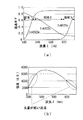
本実施例におけるハード構成は、実施例1における波長検出装置20におけるものと同等であるので、符号は同じものを使用し、各々の説明は省略する。そして、本実施例では、4分割フィルタ22の各フィルタ22a〜22cの透過率特性は図5(a)に示されるようなものとなっている。本実施例においては、フィルタ22aは波長範囲500nm〜535nmにおいて相対的に急峻な傾斜部分を有している。また、フィルタ22bは波長範囲535nm〜620nmにおいて相対的に緩やかな傾斜部分を有している。さらに、フィルタ22cは波長範囲620nm〜650nmにおいて相対的に急峻な傾斜部分を有している。
Since the hardware configuration in this embodiment is the same as that in the
図5(b)には、波長検出装置20における光源の波長毎の強度分布を示す。この強度分布においては、波長が520nm以下となる範囲及び、波長が620nm以上となる範囲では、特に光強度が弱くなっている。そうすると、この波長範囲においては受光素子23におけるSN比が低くなる危険性がある。
FIG. 5B shows the intensity distribution of the light source in the
これに対し、本実施例では、各フィルタにおける透過率特性を図5(a)に示すような透過率特性とすることで、535nm以下の波長範囲と620nm以上における波長範囲において、特に急峻な傾斜部分を有することとし、この部分における波長検出の測定精度が低下することを抑制している。 On the other hand, in this embodiment, by setting the transmittance characteristics of each filter to the transmittance characteristics as shown in FIG. 5A, a particularly steep slope is obtained in the wavelength range of 535 nm or less and the wavelength range of 620 nm or more. It has a portion, and it is suppressed that the measurement accuracy of wavelength detection in this portion is lowered.
以上、説明したように、本実施例においては、光源における波長毎の強度分布に応じて、4分割フィルタ22の各フィルタ22a〜22cの透過率特性の傾斜を決定し組み合わせることにより、光源の強度分布に関わらず精度が高く且つ精度の変動が少ない波長検出をすることが可能となった。
As described above, in the present embodiment, the intensity of the light source is determined and combined by determining the inclination of the transmittance characteristics of each of the
<実施例3>
次に、本発明の実施例3について説明する。本実施例においても実施例2と同様、ハード構成は実施例1で説明した波長検出装置20と同等である。本実施例では、フィルタが、測定対象の波長範囲において周期的に変化する透過率特性を有する例について説明する。
<Example 3>
Next, Example 3 of the present invention will be described. In this embodiment as well, as in the second embodiment, the hardware configuration is the same as that of the
図6には、本実施例におけるフィルタ22のフィルタ22a〜22cについての透過率特性を示す。本実施例においてはフィルタ22a及びフィルタ22bは、波長の変化に対して、互いに位相の異なる周期的な変化をする透過率特性を有している。これにより、非常に急峻な傾斜部を測定対象の波長範囲において多数設けることが可能となり、より精度よく、波長の検出を行うことが可能となる。また、フィルタ22a及びフィルタ22bにおける透過率特性の変化は、互いに位相が異なっているので、フィルタ22aまたはフィルタ22bの一方における透過率特性が、ピークまたはボトムで傾きが小さいあるいは水平となる波長範囲においては、フィルタ22aまたはフィルタ22bの他方が急峻な傾斜部分を有するようになっており、フィルタ22aまたはフィルタ22bのいずれかの透過率特性を用いて精度の良い波長検出を行うことが可能となっている。
FIG. 6 shows the transmittance characteristics of the
また、本実施例においては、フィルタ22cの透過率特性は、測定対象の波長範囲において緩やかに直線的に増加する特性を有している。すなわち、フィルタ22a及びフィルタ22bの透過率特性は周期的な変化をするために、何番目の周期における傾斜部分に基づく透過率なのかが判別困難となるところ、フィルタ22cによる透過率と組み合わせて測定することで、何番目の周期における傾斜部分に基づき透過率が測定されているかを判別することが可能となる。
Further, in this embodiment, the transmittance characteristic of the
以上、説明したように、本実施例においては、まず、2つのフィルタにおいて周期的で急峻な傾斜部を有する透過率特性を採用したので、測定対象となる波長範囲により多くの傾斜部分を分布させることが可能となり、波長の検出精度を向上させることが可能である。また、2つのフィルタにおける周期的な透過率特性に位相差を設け、一方のフィルタにおける透過率特性がピークまたはボトムで傾きが小さいあるいは平坦となる波長範囲では、他方のフィルタにおける透過率特性が傾斜部分を有するようにした。さらに、測定対象となる波長範囲において緩やかに単調減少または単調増加する透過率特性を有するフィルタと組み合わせることで、いずれの周期における傾斜部分に基づいて透過率が測定されているかを判別することが可能となった。以上により、より精度良く、より広い波長範囲において波長検出を行うことが可能となった。 As described above, in the present embodiment, first, the transmittance characteristics having periodic and steeply inclined portions are adopted in the two filters, so that more inclined portions are distributed in the wavelength range to be measured. This makes it possible to improve the wavelength detection accuracy. Further, a phase difference is provided in the periodic transmittance characteristics of the two filters, and the transmittance characteristic of the other filter is inclined in the wavelength range in which the transmittance characteristic of one filter is small or flat at the peak or bottom. I made it have a part. Furthermore, by combining with a filter having a transmittance characteristic that gradually decreases or increases monotonically in the wavelength range to be measured, it is possible to determine in which period the transmittance is measured based on the inclined portion. It became. As described above, it has become possible to perform wavelength detection in a wider wavelength range with higher accuracy.
図6(b)には、実際のフィルタ22aおよび、フィルタ22bの透過率特性のシュミレーション結果を示す。このように、実際のフィルタの透過率特性として、周期的に変化する特性は充分に実現可能であることが分かる。このようなフィルタはファブリペロ干渉計の原理により構成されるエタロン等を利用することにより実現可能である。
FIG. 6B shows an
また、本実施例におけるフィルタの透過率特性の山部分の半値幅は、図7に示すように、光源の波長分布の半値幅より大きくすることが望ましい。さもないと、光源の波長分布がフィルタの透過率特性における隣の周期に掛ってしまい、正確な測定が困難になるからである。この条件を満たすことで、光源がある程度の波長分布を有していたとしてもより精度の良い波長測定を行うことが可能となる。 Further, as shown in FIG. 7, it is desirable that the full width at half maximum of the mountain portion of the transmittance characteristic of the filter in this embodiment is larger than the full width at half maximum of the wavelength distribution of the light source. Otherwise, the wavelength distribution of the light source will be applied to the adjacent period in the transmittance characteristics of the filter, making accurate measurement difficult. By satisfying this condition, it is possible to perform more accurate wavelength measurement even if the light source has a certain wavelength distribution.
なお、本実施例における周期的に変化する透過率特性とは、正弦的な変化の他、台形的変化であってもよい。また、三角波的変化であってもよい。なお、透過率特性として三角波的変化を採用した場合であっても、トップまたはボトムの頂点部分においては、必ずしも鋭角な変化を実現できない場合があるので、この場合には、2つのフィルタの透過率特性の周期的変化の位相が異なるようにすべきである。また、本実施例において、2つのフ
ィルタの透過率特性について、波形を変えても構わないし、周期を変えても構わない。
The transmittance characteristic that changes periodically in this embodiment may be a trapezoidal change as well as a sinusoidal change. It may also be a triangular wave change. Even when a triangular wave change is adopted as the transmittance characteristic, it may not always be possible to realize an acute angle change at the apex portion of the top or bottom. In this case, the transmittance of the two filters The phases of the periodic changes in the properties should be different. Further, in this embodiment, the waveforms of the transmittance characteristics of the two filters may be changed or the period may be changed.
<実施例4>
次に、本発明の実施例4について説明する。本実施例においても、ハード構成は実施例1で説明した波長検出装置20と同等である。本実施例においては、4分割フィルタ22を用いた例であって、入射光の入射を4つのフィルタ22a〜22dについて、不均一にする例について説明する。
<Example 4>
Next, Example 4 of the present invention will be described. Also in this embodiment, the hardware configuration is the same as that of the
ここで、波長検出装置20によって波長検出を行う場合、4分割フィルタ22の中心から、透明板22dの方向あるいは、反対方向にずらして光を入射させた場合には、波長検出の精度は以下の(2)式のように表すことが出来る。
このように、波長精度は光量分割比αの影響を受ける。図8(b)は、透過率と波長検出精度との関係を、光量分割比αをパラメータとして示した図である。図8(b)において、横軸は透過率T、縦軸は波長検出精度σλであるが、この波長検出精度σλは、数値が小さいほど精度が高くなる数値である。図8(b)に示すように、光量分割比αが1、すなわち、光をフィルタ22aと透明板22dに均等に入射した場合と比較して、αを大きくした場合には、透過率が低い領域において波長検出精度を向上させることが可能となる。また、αを小さくすることで、透過率による波長検出精度の変化を低減することが可能である。このように、透明板を含む4つのフィルタ22a〜22dに対して、意図的に光を不均一に照射することにより、波長検出精度を適宜に制御することが可能となる。
In this way, the wavelength accuracy is affected by the light amount division ratio α. FIG. 8B is a diagram showing the relationship between the transmittance and the wavelength detection accuracy with the light amount division ratio α as a parameter. In FIG. 8B, the horizontal axis represents the transmittance T and the vertical axis represents the wavelength detection accuracy σλ. The smaller the numerical value, the higher the accuracy of the wavelength detection accuracy σλ. As shown in FIG. 8B, the light amount division ratio α is 1, that is, the transmittance is low when α is increased as compared with the case where light is evenly incident on the
なお、上記の実施例においては、透過率に関わる物理量が透過率であり、フィルタ12a、12b、22a〜22dを透過した光を受光素子によって受光する例について説明したが、上記の実施例において、フィルタ12a、12b、22a〜22dにおいて反射した光を受光素子によって受光し、反射光の強度から透過率に関わる物理量を検出しても構わない。この場合は、透過率に関わる物理量を反射率としてもよいし、反射率を1から差し引く等して、透過率を求めてもよい。
In the above embodiment, the physical quantity related to the transmittance is the transmittance, and an example in which the light transmitted through the
なお、以下には本発明の構成要件と実施例の構成とを対比可能とするために、本発明の構成要件を図面の符号付きで記載しておく。
<発明1>
複数の光学フィルタ(12a、12b)と、
光を分割して前記複数の光学フィルタ(12a、12b)を通過させる分割手段(11)と、
前記複数の光学フィルタ(12a、12b)の各々を通過または、前記複数の光学フィルタ(12a、12b)の各々により反射した光の強度を検出する複数の受光素子(13a、13b)と、
前記複数の受光素子(13a、13b)の出力から、前記複数の光学フィルタ(12a、12b)の透過率に関わる物理量を導出するとともに、前記複数の光学フィルタ(12a、12b)についての、透過率に関わる物理量と光の波長との関係である透過率特性に基づいて、前記複数の光学フィルタ(12a、12b)を通過した光の波長を導出する、演算部と、
を備える、波長検出装置(10)であって、
前記複数の光学フィルタ(12a、12b)の各々についての透過率特性は、測定対象の波長範囲における異なる波長範囲において傾斜部分を有することを特徴とする、波長検出装置(10)。
<発明2>
前記透過率に関わる物理量は透過率であって、
前記複数の光学フィルタ(12a、12b)の各々についての透過率特性において、各々の前記光学フィルタ(12a、12b)の透過率は、前記傾斜部分において略0と略1との間で変化することを特徴とする、波長検出装置。
<発明3>
前記透過率に関わる物理量は透過率であって、
前記傾斜部分のうちの少なくとも一の傾きの絶対値が0.0033(1/nm)以上であること特徴とする、請求項1または2に記載の波長検出装置。
<発明4>
前記複数の光学フィルタ(12a、12b)の各々についての透過率特性における傾斜部分は、前記測定対象の波長範囲を隙間なくカバーするように配置されることを特徴とする、請求項1から3のいずれか一項に記載の波長検出装置。
<発明5>
前記複数の光学フィルタ(12a、12b)の各々についての透過率特性のうち二以上は、前記測定対象の波長範囲において周期的に変化する曲線からなり、各々の透過率特性に係る曲線は、異なる位相を有することを特徴とする、請求項1から4のいずれか一項に記載の波長検出装置。
<発明6>
前記複数の光学フィルタ(12a、12b)の各々についての透過率特性は、前記測定対象の波長範囲において単調増加または単調減少する直線または曲線からなる透過率特性をさらに含むことを特徴とする、請求項5に記載の波長検出装置。
<発明7>
前記複数の光学フィルタは、一枚のフィルタ板(22)を異なる透過率特性を有する複数の領域(22a〜22d)に分割することで構成され、前記異なる透過率特性を有する複数の領域(22a〜22d)の少なくとも一つは透明板(22d)で形成されることを特徴とする請求項1から6のいずれか一項に記載の波長検出装置。
<発明8>
前記複数の受光素子(23a〜23d)は、同一の基板(23)上に、前記複数の領域を透過した光を各々受光可能に配置されたことを特徴とする、請求項7に記載の波長検出装置。
<発明9>
前記複数の光学フィルタ(23a〜23c)および前記透明板(22d)に入射する光の強度が不均一となるように構成されたことを特徴とする、請求項7または8に記載の波長検出装置。
<発明10>
複数の波長の光を出射する光源(71)と、
前記光源(71)から出射する光に、光軸方向に沿って色収差を生じさせる色収差付与手段(62)と、
前記色収差付与手段(62)によって色収差を生じさせた光を計測対象物に集光する対物レンズ(64)と、
前記対物レンズ(64)で集光した光のうち、前記計測対象物において合焦する光を通過させるピンホール(63)と、
請求項1から9のいずれか一項に記載の波長検出装置(10)と、を備え、
前記ピンホール(63)を通過した光の波長から、前記計測対象物の変位を計測する、共焦点計測装置(50)。
In addition, in order to make it possible to compare the constituent requirements of the present invention with the configurations of the examples, the constituent requirements of the present invention are described below with reference numerals in the drawings.
<
With multiple optical filters (12a, 12b),
A dividing means (11) that divides light and passes it through the plurality of optical filters (12a, 12b), and
A plurality of light receiving elements (13a, 13b) that pass through each of the plurality of optical filters (12a, 12b) or detect the intensity of light reflected by each of the plurality of optical filters (12a, 12b).
From the outputs of the plurality of light receiving elements (13a, 13b), the physical quantity related to the transmittance of the plurality of optical filters (12a, 12b) is derived, and the transmittance of the plurality of optical filters (12a, 12b) is derived. A calculation unit that derives the wavelength of light that has passed through the plurality of optical filters (12a, 12b) based on the transmittance characteristic that is the relationship between the physical quantity related to the light and the wavelength of light.
A wavelength detection device (10) comprising the
The wavelength detection device (10), wherein the transmittance characteristics of each of the plurality of optical filters (12a, 12b) have inclined portions in different wavelength ranges in the wavelength range to be measured.
<Invention 2>
The physical quantity related to the transmittance is the transmittance.
In the transmittance characteristics of each of the plurality of optical filters (12a, 12b), the transmittance of each of the optical filters (12a, 12b) varies between about 0 and about 1 in the inclined portion. A wavelength detection device.
<Invention 3>
The physical quantity related to the transmittance is the transmittance.
The wavelength detection device according to
<Invention 4>
<Invention 5>
Two or more of the transmittance characteristics of each of the plurality of optical filters (12a, 12b) consist of curves that change periodically in the wavelength range to be measured, and the curves related to the respective transmittance characteristics are different. The wavelength detection device according to any one of
<Invention 6>
The transmittance characteristic for each of the plurality of optical filters (12a, 12b) further includes a transmittance characteristic consisting of a straight line or a curve that monotonically increases or decreases monotonically in the wavelength range to be measured. Item 5. The wavelength detection device according to Item 5.
<Invention 7>
The plurality of optical filters are configured by dividing one filter plate (22) into a plurality of regions (22a to 22d) having different transmittance characteristics, and the plurality of regions (22a) having the different transmittance characteristics. 22d) The wavelength detection device according to any one of
<Invention 8>
The wavelength according to claim 7, wherein the plurality of light receiving elements (23a to 23d) are arranged on the same substrate (23) so as to be able to receive light transmitted through the plurality of regions. Detection device.
<Invention 9>
The wavelength detection device according to claim 7 or 8, wherein the intensity of light incident on the plurality of optical filters (23a to 23c) and the transparent plate (22d) is configured to be non-uniform. ..
<
A light source (71) that emits light of multiple wavelengths,
A chromatic aberration imparting means (62) that causes chromatic aberration along the optical axis direction in the light emitted from the light source (71), and
An objective lens (64) that collects light that has caused chromatic aberration by the chromatic aberration imparting means (62) onto an object to be measured, and an objective lens (64).
Of the light collected by the objective lens (64), a pinhole (63) through which the light focused on the measurement object passes through.
The wavelength detection device (10) according to any one of
A confocal measuring device (50) that measures the displacement of the object to be measured from the wavelength of light that has passed through the pinhole (63).
10、20・・・波長検出装置
11・・・分岐カプラ
12a、12b・・・第1、第2フィルタ
13a〜13c・・・第1〜第3受光素子
14a〜14c・・・第1〜第3分岐ファイバ
15a〜15c・・・第1〜第3集光レンズ
16・・・演算装置
22・・・4分割フィルタ
22a〜22c・・・フィルタ
22d・・・透明板
23・・・4分割受光素子
50・・・共焦点計測装置
60・・・ヘッド部
70・・・コントローラ部
80・・・モニタ部
10, 20 ...
Claims (10)
光を分割して前記複数の光学フィルタを通過させる分割手段と、
前記複数の光学フィルタの各々を通過または、前記複数の光学フィルタの各々により反射した光の強度を検出する複数の受光素子と、
前記複数の受光素子の出力から、前記複数の光学フィルタの透過率に関わる物理量を導出するとともに、前記複数の光学フィルタについての、透過率に関わる物理量と光の波長との関係である透過率特性に基づいて、前記複数の光学フィルタを通過した光の波長を導出する、演算部と、
を備える、波長検出装置であって、
前記複数の光学フィルタの各々についての透過率特性は、測定対象の波長範囲における異なる波長範囲において傾斜部分を有し、
光源の強度が相対的に弱い前記波長範囲に対しては、前記透過率特性が相対的に急峻な前記傾斜部分を有する光学フィルタが用いられることを特徴とする、波長検出装置。 With multiple optical filters
A dividing means for dividing light and passing it through the plurality of optical filters,
A plurality of light receiving elements that detect the intensity of light that has passed through each of the plurality of optical filters or is reflected by each of the plurality of optical filters.
From the outputs of the plurality of light receiving elements, the physical quantity related to the transmittance of the plurality of optical filters is derived, and the transmittance characteristic of the plurality of optical filters, which is the relationship between the physical quantity related to the transmittance and the wavelength of light. Based on, the arithmetic unit that derives the wavelength of the light that has passed through the plurality of optical filters, and
It is a wavelength detection device equipped with
Transmittance characteristics for each of the plurality of optical filters have a slope portion at a different wavelength range in the wavelength range to be measured,
A wavelength detection device, characterized in that an optical filter having the inclined portion having a relatively steep transmittance characteristic is used for the wavelength range in which the intensity of a light source is relatively weak.
前記複数の光学フィルタの各々についての透過率特性において、各々の前記光学フィルタの透過率は、前記傾斜部分において略0と略1との間で変化することを特徴とする、請求項1に記載の波長検出装置。 The physical quantity related to the transmittance is the transmittance.
The first aspect of claim 1, wherein in the transmittance characteristics of each of the plurality of optical filters, the transmittance of each of the optical filters changes between about 0 and about 1 at the inclined portion. wavelength detection device.
前記傾斜部分のうちの少なくとも一の傾きの絶対値が0.0033(1/nm)以上であることを特徴とする、請求項1または2に記載の波長検出装置。 The physical quantity related to the transmittance is the transmittance.
Wherein the absolute value of at least one inclination of said inclined portion is 0.0033 (1 / nm) or more, a wavelength detection device according to claim 1 or 2.
。 Two or more of the transmittance characteristics of each of the plurality of optical filters are composed of curves that change periodically in the wavelength range to be measured, and the curves related to the respective transmittance characteristics have different phases. The wavelength detection device according to any one of claims 1 to 4, which is characterized.
前記入射する光は、前記複数の光学フィルタと前記透明板から成る前記一枚のフィルタ板の中心部に対して、前記透明板の方向、あるいは前記透明板の反対方向にずれており、これによって波長検出精度を制御することが可能であることを特徴とする、請求項7または8に記載の波長検出装置。 It is configured so that the intensity of light incident on the plurality of optical filters and the transparent plate is non-uniform.
The incident light is deviated in the direction of the transparent plate or the opposite direction of the transparent plate with respect to the central portion of the single filter plate composed of the plurality of optical filters and the transparent plate. The wavelength detection device according to claim 7 or 8, wherein the wavelength detection accuracy can be controlled.
前記光源から出射する光に、光軸方向に沿って色収差を生じさせる色収差付与手段と、
前記色収差付与手段によって色収差を生じさせた光を計測対象物に集光する対物レンズと、
前記対物レンズで集光した光のうち、前記計測対象物において合焦する光を通過させるピンホールと、
請求項1から9のいずれか一項に記載の波長検出装置と、を備え、
前記ピンホールを通過した光の波長から、前記計測対象物の変位を計測する、共焦点計測装置。 A light source for emitting light of a plurality of wavelengths,
A means for imparting chromatic aberration that causes chromatic aberration in the light emitted from the light source along the optical axis direction,
An objective lens that collects light that has caused chromatic aberration by the chromatic aberration imparting means onto an object to be measured, and an objective lens.
Of the light collected by the objective lens, a pinhole that allows the light that is in focus in the measurement object to pass through.
The wavelength detection device according to any one of claims 1 to 9 is provided.
A confocal measuring device that measures the displacement of the object to be measured from the wavelength of light that has passed through the pinhole.
Priority Applications (5)
| Application Number | Priority Date | Filing Date | Title |
|---|---|---|---|
| JP2018044588A JP6919603B2 (en) | 2018-03-12 | 2018-03-12 | Wavelength detector and confocal measuring device |
| PCT/JP2019/010010 WO2019176938A1 (en) | 2018-03-12 | 2019-03-12 | Wavelength detection device and confocal measurement device |
| EP19766776.9A EP3767258A4 (en) | 2018-03-12 | 2019-03-12 | Wavelength detection device and confocal measurement device |
| US16/970,377 US11262238B2 (en) | 2018-03-12 | 2019-03-12 | Wavelength detection device and confocal measurement device |
| CN201980011576.9A CN111684244B (en) | 2018-03-12 | 2019-03-12 | Wavelength detection device and confocal measurement device |
Applications Claiming Priority (1)
| Application Number | Priority Date | Filing Date | Title |
|---|---|---|---|
| JP2018044588A JP6919603B2 (en) | 2018-03-12 | 2018-03-12 | Wavelength detector and confocal measuring device |
Publications (2)
| Publication Number | Publication Date |
|---|---|
| JP2019158527A JP2019158527A (en) | 2019-09-19 |
| JP6919603B2 true JP6919603B2 (en) | 2021-08-18 |
Family
ID=67906808
Family Applications (1)
| Application Number | Title | Priority Date | Filing Date |
|---|---|---|---|
| JP2018044588A Active JP6919603B2 (en) | 2018-03-12 | 2018-03-12 | Wavelength detector and confocal measuring device |
Country Status (5)
| Country | Link |
|---|---|
| US (1) | US11262238B2 (en) |
| EP (1) | EP3767258A4 (en) |
| JP (1) | JP6919603B2 (en) |
| CN (1) | CN111684244B (en) |
| WO (1) | WO2019176938A1 (en) |
Families Citing this family (2)
| Publication number | Priority date | Publication date | Assignee | Title |
|---|---|---|---|---|
| FR3104254B1 (en) * | 2019-12-04 | 2021-12-03 | Safran | Optical spectrometer and associated source characterization method |
| US11460347B2 (en) * | 2020-02-24 | 2022-10-04 | Lumentum Operations Llc | Optical frequency measurement device |
Family Cites Families (17)
| Publication number | Priority date | Publication date | Assignee | Title |
|---|---|---|---|---|
| US3748035A (en) * | 1971-12-28 | 1973-07-24 | Xerox Corp | Method for sequential illumination in a polychrome process |
| JPH0658817A (en) | 1992-08-12 | 1994-03-04 | Yokogawa Electric Corp | Light wavelength meter |
| SE514188C2 (en) | 1999-02-17 | 2001-01-22 | Altitun Ab | Method for characterizing a tunable laser and determining the current wavelength |
| WO2002075877A2 (en) | 2001-03-15 | 2002-09-26 | Digital Optics Corporation | Integrated wavelength locker for use with more than one wavelength and associated methods |
| JP2002071459A (en) * | 2000-08-25 | 2002-03-08 | Ntt Electornics Corp | Light wavelength monitoring device |
| JP2006086955A (en) * | 2004-09-17 | 2006-03-30 | Fujitsu Ltd | Transmission characteristic evaluation system and pseudo transmission path apparatus thereof |
| GB2399875B (en) * | 2003-03-24 | 2006-02-22 | Tsunami Photonics Ltd | Optical wavelength meter |
| US7459713B2 (en) * | 2003-08-14 | 2008-12-02 | Microptix Technologies, Llc | Integrated sensing system approach for handheld spectral measurements having a disposable sample handling apparatus |
| KR20090040343A (en) | 2006-07-18 | 2009-04-23 | 티아이알 테크놀로지 엘피 | Method and apparatus for determining intensities and peak wavelengths of light |
| US20080137061A1 (en) * | 2006-12-07 | 2008-06-12 | Christopher John Rush | Displacement Measurement Sensor Using the Confocal Principle |
| US8432553B2 (en) * | 2009-10-08 | 2013-04-30 | Massachusetts Institute Of Technology | Phase from defocused color images |
| WO2011121896A1 (en) * | 2010-03-31 | 2011-10-06 | コニカミノルタセンシング株式会社 | Optical system for measurement, and color luminance meter and colorimeter using the same |
| JP5790178B2 (en) * | 2011-03-14 | 2015-10-07 | オムロン株式会社 | Confocal measuring device |
| US8878114B2 (en) * | 2012-08-16 | 2014-11-04 | Nanohmics, Inc. | Apparatus and methods for locating source of and analyzing electromagnetic radiation |
| JP6347070B2 (en) * | 2014-06-03 | 2018-06-27 | コニカミノルタ株式会社 | Spectroscopic analyzer |
| US11019316B1 (en) * | 2018-02-09 | 2021-05-25 | Tdone, Llc | Sequential spectral imaging |
| DE102018114860A1 (en) * | 2018-06-20 | 2019-12-24 | Precitec Optronik Gmbh | Device and method for the optical measurement of a measurement object |
-
2018
- 2018-03-12 JP JP2018044588A patent/JP6919603B2/en active Active
-
2019
- 2019-03-12 US US16/970,377 patent/US11262238B2/en active Active
- 2019-03-12 WO PCT/JP2019/010010 patent/WO2019176938A1/en unknown
- 2019-03-12 CN CN201980011576.9A patent/CN111684244B/en active Active
- 2019-03-12 EP EP19766776.9A patent/EP3767258A4/en active Pending
Also Published As
| Publication number | Publication date |
|---|---|
| US11262238B2 (en) | 2022-03-01 |
| JP2019158527A (en) | 2019-09-19 |
| EP3767258A4 (en) | 2021-12-01 |
| WO2019176938A1 (en) | 2019-09-19 |
| CN111684244A (en) | 2020-09-18 |
| EP3767258A1 (en) | 2021-01-20 |
| US20210088383A1 (en) | 2021-03-25 |
| CN111684244B (en) | 2023-07-28 |
Similar Documents
| Publication | Publication Date | Title |
|---|---|---|
| US7791731B2 (en) | Partial coherence interferometer with measurement ambiguity resolution | |
| US8587772B2 (en) | Chromatic point sensor configuration including real time spectrum compensation | |
| US10228551B1 (en) | Device and method for optically measuring a measurement object | |
| KR101750188B1 (en) | Confocal measurement device | |
| CN109791040B (en) | Method and device for optical surface measurement by means of a chromatic confocal sensor | |
| KR102115498B1 (en) | Confocal measurement device | |
| KR20210092821A (en) | optical measuring device | |
| JP6919603B2 (en) | Wavelength detector and confocal measuring device | |
| CA2070330C (en) | High resolution spectroscopy system | |
| US10151576B2 (en) | Confocally chromatic sensor for determining coordinates of a measurement object | |
| US20190310189A1 (en) | Apparatus and method for determining a refractive index | |
| US20150247798A1 (en) | Optical system and optical quality measuring apparatus | |
| KR101628761B1 (en) | surface shape measuring appatstus using asymmetric interferometer | |
| TWI755690B (en) | Optical measurement device, optical measurement method, and optical measurement program | |
| US9612112B2 (en) | Optical system and optical quality measuring apparatus | |
| JP2012093197A (en) | Height measurement device | |
| JPH064611U (en) | Optical distance measuring device | |
| TWI723324B (en) | Optical measurement device and optical measurement method | |
| US20160061587A1 (en) | Device for Interferential Distance Measurement | |
| KR101730445B1 (en) | optical-phase imaging system | |
| JP7445201B2 (en) | Optical measurement device and optical measurement method | |
| CN112432600B (en) | Optical measuring device | |
| JP2014202645A (en) | Measuring instrument | |
| JP2015194347A (en) | Distance metering device and method | |
| JP2016017755A (en) | Device and method for measuring distance |
Legal Events
| Date | Code | Title | Description |
|---|---|---|---|
| A621 | Written request for application examination |
Free format text: JAPANESE INTERMEDIATE CODE: A621 Effective date: 20200310 |
|
| A131 | Notification of reasons for refusal |
Free format text: JAPANESE INTERMEDIATE CODE: A131 Effective date: 20201110 |
|
| A521 | Request for written amendment filed |
Free format text: JAPANESE INTERMEDIATE CODE: A523 Effective date: 20210107 |
|
| TRDD | Decision of grant or rejection written | ||
| A01 | Written decision to grant a patent or to grant a registration (utility model) |
Free format text: JAPANESE INTERMEDIATE CODE: A01 Effective date: 20210622 |
|
| A61 | First payment of annual fees (during grant procedure) |
Free format text: JAPANESE INTERMEDIATE CODE: A61 Effective date: 20210705 |
|
| R150 | Certificate of patent or registration of utility model |
Ref document number: 6919603 Country of ref document: JP Free format text: JAPANESE INTERMEDIATE CODE: R150 |
|
| R250 | Receipt of annual fees |
Free format text: JAPANESE INTERMEDIATE CODE: R250 |