JP6917973B2 - Folding display device - Google Patents
Folding display device Download PDFInfo
- Publication number
- JP6917973B2 JP6917973B2 JP2018248516A JP2018248516A JP6917973B2 JP 6917973 B2 JP6917973 B2 JP 6917973B2 JP 2018248516 A JP2018248516 A JP 2018248516A JP 2018248516 A JP2018248516 A JP 2018248516A JP 6917973 B2 JP6917973 B2 JP 6917973B2
- Authority
- JP
- Japan
- Prior art keywords
- housing
- state
- mobile terminal
- display
- support
- Prior art date
- Legal status (The legal status is an assumption and is not a legal conclusion. Google has not performed a legal analysis and makes no representation as to the accuracy of the status listed.)
- Active
Links
- 230000009975 flexible effect Effects 0.000 claims description 106
- 239000000853 adhesive Substances 0.000 claims description 86
- 230000001070 adhesive effect Effects 0.000 claims description 84
- 230000000295 complement effect Effects 0.000 claims 2
- 230000004048 modification Effects 0.000 description 87
- 238000012986 modification Methods 0.000 description 87
- 238000005452 bending Methods 0.000 description 33
- 210000000078 claw Anatomy 0.000 description 12
- 238000000034 method Methods 0.000 description 10
- 230000003014 reinforcing effect Effects 0.000 description 4
- 238000013459 approach Methods 0.000 description 3
- 239000012790 adhesive layer Substances 0.000 description 1
- 238000004804 winding Methods 0.000 description 1
Images


Classifications
-
- G—PHYSICS
- G09—EDUCATION; CRYPTOGRAPHY; DISPLAY; ADVERTISING; SEALS
- G09F—DISPLAYING; ADVERTISING; SIGNS; LABELS OR NAME-PLATES; SEALS
- G09F9/00—Indicating arrangements for variable information in which the information is built-up on a support by selection or combination of individual elements
- G09F9/30—Indicating arrangements for variable information in which the information is built-up on a support by selection or combination of individual elements in which the desired character or characters are formed by combining individual elements
- G09F9/301—Indicating arrangements for variable information in which the information is built-up on a support by selection or combination of individual elements in which the desired character or characters are formed by combining individual elements flexible foldable or roll-able electronic displays, e.g. thin LCD, OLED
-
- G—PHYSICS
- G06—COMPUTING; CALCULATING OR COUNTING
- G06F—ELECTRIC DIGITAL DATA PROCESSING
- G06F1/00—Details not covered by groups G06F3/00 - G06F13/00 and G06F21/00
- G06F1/16—Constructional details or arrangements
- G06F1/1613—Constructional details or arrangements for portable computers
- G06F1/1633—Constructional details or arrangements of portable computers not specific to the type of enclosures covered by groups G06F1/1615 - G06F1/1626
- G06F1/1637—Details related to the display arrangement, including those related to the mounting of the display in the housing
- G06F1/1652—Details related to the display arrangement, including those related to the mounting of the display in the housing the display being flexible, e.g. mimicking a sheet of paper, or rollable
-
- G—PHYSICS
- G06—COMPUTING; CALCULATING OR COUNTING
- G06F—ELECTRIC DIGITAL DATA PROCESSING
- G06F1/00—Details not covered by groups G06F3/00 - G06F13/00 and G06F21/00
- G06F1/16—Constructional details or arrangements
- G06F1/1613—Constructional details or arrangements for portable computers
- G06F1/1615—Constructional details or arrangements for portable computers with several enclosures having relative motions, each enclosure supporting at least one I/O or computing function
- G06F1/1616—Constructional details or arrangements for portable computers with several enclosures having relative motions, each enclosure supporting at least one I/O or computing function with folding flat displays, e.g. laptop computers or notebooks having a clamshell configuration, with body parts pivoting to an open position around an axis parallel to the plane they define in closed position
-
- G—PHYSICS
- G06—COMPUTING; CALCULATING OR COUNTING
- G06F—ELECTRIC DIGITAL DATA PROCESSING
- G06F1/00—Details not covered by groups G06F3/00 - G06F13/00 and G06F21/00
- G06F1/16—Constructional details or arrangements
- G06F1/1613—Constructional details or arrangements for portable computers
- G06F1/1615—Constructional details or arrangements for portable computers with several enclosures having relative motions, each enclosure supporting at least one I/O or computing function
- G06F1/1624—Constructional details or arrangements for portable computers with several enclosures having relative motions, each enclosure supporting at least one I/O or computing function with sliding enclosures, e.g. sliding keyboard or display
-
- G—PHYSICS
- G06—COMPUTING; CALCULATING OR COUNTING
- G06F—ELECTRIC DIGITAL DATA PROCESSING
- G06F1/00—Details not covered by groups G06F3/00 - G06F13/00 and G06F21/00
- G06F1/16—Constructional details or arrangements
- G06F1/1613—Constructional details or arrangements for portable computers
- G06F1/1633—Constructional details or arrangements of portable computers not specific to the type of enclosures covered by groups G06F1/1615 - G06F1/1626
- G06F1/1637—Details related to the display arrangement, including those related to the mounting of the display in the housing
- G06F1/1641—Details related to the display arrangement, including those related to the mounting of the display in the housing the display being formed by a plurality of foldable display components
-
- G—PHYSICS
- G06—COMPUTING; CALCULATING OR COUNTING
- G06F—ELECTRIC DIGITAL DATA PROCESSING
- G06F1/00—Details not covered by groups G06F3/00 - G06F13/00 and G06F21/00
- G06F1/16—Constructional details or arrangements
- G06F1/1613—Constructional details or arrangements for portable computers
- G06F1/1633—Constructional details or arrangements of portable computers not specific to the type of enclosures covered by groups G06F1/1615 - G06F1/1626
- G06F1/1675—Miscellaneous details related to the relative movement between the different enclosures or enclosure parts
- G06F1/1681—Details related solely to hinges
-
- H—ELECTRICITY
- H04—ELECTRIC COMMUNICATION TECHNIQUE
- H04M—TELEPHONIC COMMUNICATION
- H04M1/00—Substation equipment, e.g. for use by subscribers
- H04M1/02—Constructional features of telephone sets
- H04M1/0202—Portable telephone sets, e.g. cordless phones, mobile phones or bar type handsets
- H04M1/0206—Portable telephones comprising a plurality of mechanically joined movable body parts, e.g. hinged housings
- H04M1/0208—Portable telephones comprising a plurality of mechanically joined movable body parts, e.g. hinged housings characterized by the relative motions of the body parts
- H04M1/0214—Foldable telephones, i.e. with body parts pivoting to an open position around an axis parallel to the plane they define in closed position
- H04M1/0216—Foldable in one direction, i.e. using a one degree of freedom hinge
- H04M1/022—The hinge comprising two parallel pivoting axes
-
- H—ELECTRICITY
- H04—ELECTRIC COMMUNICATION TECHNIQUE
- H04M—TELEPHONIC COMMUNICATION
- H04M1/00—Substation equipment, e.g. for use by subscribers
- H04M1/02—Constructional features of telephone sets
- H04M1/0202—Portable telephone sets, e.g. cordless phones, mobile phones or bar type handsets
- H04M1/0206—Portable telephones comprising a plurality of mechanically joined movable body parts, e.g. hinged housings
- H04M1/0208—Portable telephones comprising a plurality of mechanically joined movable body parts, e.g. hinged housings characterized by the relative motions of the body parts
- H04M1/0235—Slidable or telescopic telephones, i.e. with a relative translation movement of the body parts; Telephones using a combination of translation and other relative motions of the body parts
-
- H—ELECTRICITY
- H04—ELECTRIC COMMUNICATION TECHNIQUE
- H04M—TELEPHONIC COMMUNICATION
- H04M1/00—Substation equipment, e.g. for use by subscribers
- H04M1/02—Constructional features of telephone sets
- H04M1/0202—Portable telephone sets, e.g. cordless phones, mobile phones or bar type handsets
- H04M1/0206—Portable telephones comprising a plurality of mechanically joined movable body parts, e.g. hinged housings
- H04M1/0247—Portable telephones comprising a plurality of mechanically joined movable body parts, e.g. hinged housings comprising more than two body parts
-
- H—ELECTRICITY
- H04—ELECTRIC COMMUNICATION TECHNIQUE
- H04M—TELEPHONIC COMMUNICATION
- H04M1/00—Substation equipment, e.g. for use by subscribers
- H04M1/02—Constructional features of telephone sets
- H04M1/0202—Portable telephone sets, e.g. cordless phones, mobile phones or bar type handsets
- H04M1/026—Details of the structure or mounting of specific components
- H04M1/0266—Details of the structure or mounting of specific components for a display module assembly
- H04M1/0268—Details of the structure or mounting of specific components for a display module assembly including a flexible display panel
Description
本発明は、折り畳み式表示装置、特に、一対の筐体の内側に折り畳み可能なディスプレイを設けた装置に関する。 The present invention relates to a foldable display device, particularly a device in which a foldable display is provided inside a pair of housings.
近年、携帯電話やスマートフォンなどの携帯端末装置が普及している。特に、携帯電話においては、折り畳み式の端末が広く普及している。その理由は、使用時には画面が大きい方が望ましい反面、携帯時には小型化されることが望ましいからである。また、スマートフォンにおいても、シームレスなディスプレイを用いた折り畳み可能な端末が提案されている(例えば、特許文献1を参照)。 In recent years, mobile terminal devices such as mobile phones and smartphones have become widespread. In particular, in mobile phones, foldable terminals are widely used. The reason is that while it is desirable to have a large screen when using it, it is desirable to make it smaller when carrying it. Also, for smartphones, foldable terminals using a seamless display have been proposed (see, for example, Patent Document 1).
特許文献1の折り畳み式スマートフォンは、二軸ヒンジを採用している。この場合、折り畳みを行うと、ディスプレイの屈曲部分がディスプレイの元々あった基準位置から下方に潜り込む形になる。この屈曲部分を避けるために、ディスプレイを支えていた土台も下方に逃げる必要がある。したがって、構造が複雑になる。
また、折り畳み式スマートフォンとして、筐体をZ字状に折り畳むことも検討されている。これが実現すれば、折り畳み時にはスマホサイズ、広げたときにはタブレットサイズにすることができ、つまり折り畳み式の利点を最大にできる。ただし、この場合、ディスプレイの外曲げと内曲げが両立する構造を実現する必要がある。
The foldable smartphone of
Further, as a foldable smartphone, folding the housing into a Z shape is also being considered. If this is achieved, it will be possible to make it smartphone-sized when folded and tablet-sized when unfolded, which means that the advantages of the foldable type can be maximized. However, in this case, it is necessary to realize a structure in which the outward bending and the inward bending of the display are compatible.
本発明の目的は、折り畳み式表示装置において、第1筐体と第2筐体とを簡単な構造で回動可能に連結することにある。
本発明の他の目的は、折り畳み式表示装置において、筐体をZ字状に折り畳み可能にすることにある。
An object of the present invention is to rotatably connect a first housing and a second housing with a simple structure in a foldable display device.
Another object of the present invention is to make the housing foldable in a Z shape in a foldable display device.
以下に、課題を解決するための手段として複数の態様を説明する。これら態様は、必要に応じて任意に組み合せることができる。 Hereinafter, a plurality of aspects will be described as means for solving the problem. These aspects can be arbitrarily combined as needed.
本発明の一見地に係る折り畳み式表示装置は、複数の筐体が折り畳み可能に連結された装置であって、第1筐体と、第2筐体と、回動連結部と、フレキシブルなディスプレイと、支持部材とを備えている。
回動連結部は、第1筐体と第2筐体が開くことで平面状態になる開き状態と、第1筐体と第2筐体が閉じることで内側に折り曲げられた状態になる閉じ状態とが可能になるように、第1筐体と第2筐体とを連結している。
ディスプレイは、第1筐体及び第2筐体の一面を覆うように配置されている。
支持部材は、第1筐体と第2筐体との間に配置され、ディスプレイが開き状態になるときにディスプレイを支持する平坦支持面を有する。
ディスプレイは、第1筐体及び第2筐体に接着された接着部と、第1筐体と第2筐体との間で支持部材の平坦支持面から離れることができる非接着部とを有する。
この装置では、第1筐体と第2筐体が開いた状態では、ディスプレイの非接着部が支持部材の平坦支持面によって支持される。第1筐体と第2筐体が閉じた状態では、ディスプレイの非接着部が支持部材の平坦支持面から離れて屈曲する。
この装置では、第1筐体と第2筐体とを連結する構造が簡単になる。
The foldable display device according to the first aspect of the present invention is a device in which a plurality of housings are foldably connected, and is a first housing, a second housing, a rotary connecting portion, and a flexible display. And a support member.
The rotary connecting portion is in an open state in which the first housing and the second housing are opened to be in a flat state, and a closed state in which the first housing and the second housing are closed to be in an inwardly bent state. The first housing and the second housing are connected so as to enable.
The display is arranged so as to cover one surface of the first housing and the second housing.
The support member is arranged between the first housing and the second housing, and has a flat support surface that supports the display when the display is in the open state.
The display has an adhesive portion bonded to the first housing and the second housing, and a non-adhesive portion capable of being separated from the flat support surface of the support member between the first housing and the second housing. ..
In this device, when the first housing and the second housing are open, the non-adhesive portion of the display is supported by the flat support surface of the support member. When the first housing and the second housing are closed, the non-adhesive portion of the display bends away from the flat support surface of the support member.
In this device, the structure for connecting the first housing and the second housing becomes simple.
回動連結部の回動軸が延びる方向に見て、回動連結部の回動中心は平坦支持面に一致していてもよい。
ディスプレイの非接着部は、ディスプレイが閉じ状態になると、平坦支持面から離れた位置で屈曲してもよい。
この装置では、第1筐体と第2筐体が閉じた状態では、ディスプレイの非接着部が平坦支持面から上方に離れるように屈曲する。
When viewed in the direction in which the rotation shaft of the rotation connection portion extends, the rotation center of the rotation connection portion may coincide with the flat support surface.
The non-adhesive portion of the display may be bent at a position away from the flat support surface when the display is closed.
In this device, when the first housing and the second housing are closed, the non-adhesive portion of the display is bent so as to be separated upward from the flat support surface.
支持部材は、回動連結部の回動軸が延びる方向に見て、回動連結部の回動中心を中心とする円弧の一部に対応する第1湾曲面及び第2湾曲面を有していてもよい。
第1筐体及び第2筐体は、各々、第1湾曲面及び第2湾曲面を相補的に支持する第3湾曲面及び第4湾曲面を有していてもよい。
この装置では、第1筐体と第2筐体は、開閉動作中には支持部材の湾曲面によって回動方向に案内される。したがって、第1筐体と第2筐体の開閉動作が安定する。
The support member has a first curved surface and a second curved surface corresponding to a part of an arc centered on the rotation center of the rotation connecting portion when viewed in the direction in which the rotation shaft of the rotation connecting portion extends. You may be.
The first housing and the second housing may have a third curved surface and a fourth curved surface that complementarily support the first curved surface and the second curved surface, respectively.
In this device, the first housing and the second housing are guided in the rotational direction by the curved surface of the support member during the opening / closing operation. Therefore, the opening / closing operation of the first housing and the second housing is stable.
支持部材は、第1筐体側を向いた第1当接部と、第2筐体側を向いた第2当接部とを有していてもよい。
第1筐体及び第2筐体は、それぞれ、ディスプレイが開き状態で第1当接部と第2当接部に対して回転方向に離れており、ディスプレイが閉じ状態になると、第1当接部と第2当接部にそれぞれ当接する第3当接部及び第4当接部を有していてもよい。
この装置では、第1筐体と第2筐体が閉じられると、支持部材の第1当接部と第2当接部にそれぞれ第1筐体の第3当接部と第2筐体の第4当接部が当接する。したがって、支持部材は、第1筐体と第2筐体との間で回動不能に保持され、がたつきにくい。
The support member may have a first contact portion facing the first housing side and a second contact portion facing the second housing side.
The first housing and the second housing are separated from each other in the rotational direction with respect to the first contact portion and the second contact portion in the open state of the display, respectively, and when the display is closed, the first contact portion is in contact with the first housing. It may have a third contact portion and a fourth contact portion that come into contact with the portion and the second contact portion, respectively.
In this device, when the first housing and the second housing are closed, the first contact portion and the second contact portion of the support member are contacted with the third contact portion and the second housing of the first housing, respectively. The fourth contact portion comes into contact. Therefore, the support member is held non-rotatably between the first housing and the second housing, and is less likely to rattle.
折り畳み式表示装置は、第1弾性覆い部材をさらに備えていてもよい。第1弾性覆い部材は、第2筐体の第1筐体側端に固定され、第1筐体と第2筐体が開き状態から閉じ状態に移行するとき及び閉じ状態において、支持部材の外側を覆ってもよい。
この装置では、第1筐体及び第2筐体が閉じられた状態又は閉じられる途中の状態では、第1弾性覆い部材が支持部材の外側を覆う。したがって、上記の状態で操作者が支持部材を触ることがない。
The foldable display device may further include a first elastic covering member. The first elastic covering member is fixed to the end of the second housing on the side of the first housing, and when the first housing and the second housing shift from the open state to the closed state and in the closed state, the outside of the support member is covered. You may cover it.
In this device, the first elastic covering member covers the outside of the support member when the first housing and the second housing are closed or in the process of being closed. Therefore, the operator does not touch the support member in the above state.
折り畳み式表示装置は、第2弾性覆い部材をさらに備えていてもよい。第2弾性覆い部材は、第2筐体の第1筐体側端に固定されており、第1筐体と第2筐体が開き状態のときにディスプレイの非接着部を支持している。第2弾性覆い部材は、第1筐体と第2筐体が閉じ状態のときに、屈曲する非接着部の外側を湾曲した状態で覆ってもよい。
この装置では、第1筐体と第2筐体が閉じ状態になると、第2弾性部材が湾曲した状態で非接触部を覆う。このように第2弾性覆い部材が非接触部のための収納空間を確保するので、折り畳んだ状態での装置の厚みを小さくできる。
The foldable display device may further include a second elastic covering member. The second elastic covering member is fixed to the end of the second housing on the side of the first housing, and supports the non-adhesive portion of the display when the first housing and the second housing are in the open state. The second elastic covering member may cover the outside of the bent non-adhesive portion in a curved state when the first housing and the second housing are closed.
In this device, when the first housing and the second housing are closed, the second elastic member covers the non-contact portion in a curved state. Since the second elastic covering member secures a storage space for the non-contact portion in this way, the thickness of the device in the folded state can be reduced.
本発明の他の見地に係る折り畳み式表示装置は、複数の筐体が折り畳み可能に連結された装置であって、第1筐体と、第2筐体と、第3筐体と、フレキシブルなディスプレイと、第1回動連結部と、第2回動連結部と、移動支持部材とを備えている。
ディスプレイは、第1筐体、第2筐体及び第3筐体の一面を覆うように配置され、第1筐体及び第3筐体の主要部にそれぞれ接着された第1接着部及び第2接着部と、第1接着部と第2接着部との間で第1筐体、第2筐体及び第3筐体に対して離れることができる非接着部とを有する。
第1回動連結部は、第1筐体と第2筐体が開いてディスプレイが平面状態になる開き状態と、第1筐体と第2筐体が閉じてディスプレイが外側に折り曲げられた状態になる閉じ状態とが可能になるように、第1筐体と第2筐体とを連結している。
第2回動連結部は、第2筐体と第3筐体が開いてディスプレイが平面状態になる開き状態と、第2筐体と第3筐体が閉じてディスプレイが内側に折り曲げられた状態になる閉じ状態とが可能になるように、第2筐体と第3筐体とを連結している。
移動支持部材は、第2筐体内において第1筐体側と第3筐体側とに移動可能に配置され、非接着部に接着されて非接着部の少なくとも一部を平面状態になるように支持する。
この装置では、移動支持部材は、第2筐体において、ディスプレイの非接着部を平面状態になるように支持する。第1筐体、第2筐体、及び第3筐体を開閉するときに、支持スライダは第2筐体内において移動する。
この装置では、筐体をZ字状に折り畳み可能にすることができる。
The foldable display device according to another aspect of the present invention is a device in which a plurality of housings are foldably connected to each other, and is flexible with a first housing, a second housing, and a third housing. It includes a display, a first rotation connecting portion, a second rotation connecting portion, and a moving support member.
The display is arranged so as to cover one surface of the first housing, the second housing, and the third housing, and the first adhesive portion and the second adhesive portion adhered to the main portions of the first housing and the third housing, respectively. It has an adhesive portion and a non-adhesive portion that can be separated from the first housing, the second housing, and the third housing between the first adhesive portion and the second adhesive portion.
The first rotation connecting portion has an open state in which the first housing and the second housing are opened to make the display flat, and a state in which the first housing and the second housing are closed and the display is bent outward. The first housing and the second housing are connected so as to enable a closed state.
The second rotation connecting portion has an open state in which the second housing and the third housing are opened to make the display flat, and a state in which the second housing and the third housing are closed and the display is bent inward. The second housing and the third housing are connected so as to enable a closed state.
The movable support member is movably arranged on the first housing side and the third housing side in the second housing, and is adhered to the non-adhesive portion to support at least a part of the non-adhesive portion in a flat state. ..
In this device, the moving support member supports the non-adhesive portion of the display in a flat state in the second housing. When opening and closing the first housing, the second housing, and the third housing, the support slider moves in the second housing.
In this device, the housing can be made foldable in a Z shape.
移動支持部材は、支持スライダであってもよい。
折り畳み式表示装置は、第2筐体と支持スライダとを連結し、第1筐体と第2筐体が閉じてディスプレイが外側に屈曲する閉じ状態では、支持スライダを第1回動連結部側から第2回動連結部側に向けて付勢する付勢部材をさらに備えていてもよい。
この装置では、第1筐体と第2筐体を外曲げに閉じるときには、付勢部材が支持スライダを第2回動連結部側に向けて付勢するので、ディスプレイの第1回動連結部付近でのテンションが高くなくなる。その結果、第1筐体と第2筐体の外曲げ部でのディスプレイの弛みが抑えられる。
The moving support member may be a support slider.
The foldable display device connects the second housing and the support slider, and in the closed state where the first housing and the second housing are closed and the display is bent outward, the support slider is connected to the first rotation connecting portion side. It may be further provided with an urging member for urging toward the second rotation connecting portion side.
In this device, when the first housing and the second housing are closed outwardly, the urging member biases the support slider toward the second rotation connecting portion, so that the first rotation connecting portion of the display is used. The tension in the vicinity is not high. As a result, slackening of the display at the outer bent portions of the first housing and the second housing is suppressed.
第2筐体は、支持スライダを第1筐体側と第3筐体側とに移動可能にガイドするガイド部を有していてもよい。
この装置では、支持スライダが第2筐体内で移動するときにガイド部によってガイドされるので、支持スライダの移動が安定する。
The second housing may have a guide portion that movably guides the support slider between the first housing side and the third housing side.
In this device, when the support slider moves in the second housing, it is guided by the guide portion, so that the movement of the support slider is stable.
支持スライダは、第2筐体の第1筐体と第3筐体との連結方向に交差する方向に長く延びていてもよい。
この装置では、支持スライダが長く延びているので、ディスプレイが第2筐体部分において支持スライダに支持される領域が、広くなる。
The support slider may extend long in a direction intersecting the connecting direction between the first housing and the third housing of the second housing.
In this device, since the support slider is extended long, the area where the display is supported by the support slider in the second housing portion is widened.
折り畳み式表示装置は、角度調整機構をさらに備えていてもよい。リンク部材は、第2筐体に対する第1筐体の角度と第3筐体の角度が常に同じになるように第1筐体と第3筐体とを連結してもよい。
この装置では、角度調整機構によって、開閉動作の途中で、第2筐体に対する第1筐体の角度と第3筐体の角度が常に同じになる。
The foldable display device may further include an angle adjusting mechanism. The link member may connect the first housing and the third housing so that the angle of the first housing with respect to the second housing and the angle of the third housing are always the same.
In this device, the angle adjusting mechanism keeps the angle of the first housing and the angle of the third housing with respect to the second housing always the same during the opening / closing operation.
本発明に係る折り畳み式表示装置では、第1筐体と第2筐体が簡単な構造で回動可能に連結される。
本発明に係る折り畳み式表示装置では、筐体をZ字状に折り畳み可能にすることができる。
In the foldable display device according to the present invention, the first housing and the second housing are rotatably connected with a simple structure.
In the foldable display device according to the present invention, the housing can be made foldable in a Z shape.
1.第1実施形態
(1)概略説明
図1〜図3を用いて、第1実施形態に係る携帯端末1(折り畳み式表示装置の一例)を説明する。図1は、第1実施形態の携帯端末(開いた平面状態)の斜視図である。図2は、携帯端末(開いた平面状態)の側面図である。図3は、携帯端末(折り畳み状態)の側面図である。
携帯端末1は、二つ折りに折り畳み可能な装置であり、例えば、スマートフォン、タブレット、携帯電話、ゲーム機、電子書籍端末である。
1. 1. First Embodiment (1) Schematic Description The mobile terminal 1 (an example of a foldable display device) according to the first embodiment will be described with reference to FIGS. 1 to 3. FIG. 1 is a perspective view of the mobile terminal (open flat state) of the first embodiment. FIG. 2 is a side view of the mobile terminal (open flat state). FIG. 3 is a side view of the mobile terminal (folded state).
The
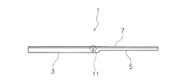
図1に示すように、携帯端末1は、第1筐体3と、第2筐体5と、フレキシブルディスプレイ7と、回動連結部9と、支持部材11と、を備える。
第1筐体3及び第2筐体5は、平面視矩形の平板状部材であり、平面視においてほぼ同一の大きさを有している。第1筐体3及び第2筐体5は、内部空間を有している。なお、第1筐体3と第2筐体5は、長辺同士が近接している。以下、図1において、第1筐体3と第2筐体5が並んだ方向を「配列方向」とし、第1筐体3と第2筐体5が近接する側を「配列方向内側」とし、そこから離れる側を「配列方向外側」とする。さらに、第1筐体3と第2筐体5の長辺が延びる方向を「長辺延び方向」とする。
なお、第1筐体3及び第2筐体5は、フレキシブルディスプレイ7における画像表示の制御等を行う制御回路等(図示せず)を内部に備えている。
As shown in FIG. 1, the
The
The
回動連結部9は、第1筐体3の配列方向内側長辺と第2筐体5の配列方向内側長辺を連結している。これにより、第1筐体3と第2筐体5が開くことで平面状態になる開き状態(使用状態)と、第1筐体3と第2筐体5が閉じることで内側に折り曲げられた状態になる閉じ状態(収納状態)とが可能になっている。
図1及び図2に示すように、携帯端末1が開き状態(使用状態)のとき、第1筐体3と第2筐体5は、主面同士が略同一面となるように配置される。
図3に示すように、携帯端末1が閉じ状態(折り畳み状態)のとき、第1筐体3と第2筐体5は、主面同士が互いに向き合って密着し、裏面同士がそれぞれ外側を向くように配置される。
The rotary connecting portion 9 connects the inner long side in the arrangement direction of the
As shown in FIGS. 1 and 2, when the
As shown in FIG. 3, when the
フレキシブルディスプレイ7は、シームレス(継目なし)の一枚ものであり、第1筐体3及び第2筐体5の主面に対して、全体を覆うように取り付けられている。言い換えると、第1筐体3及び第2筐体5は、フレキシブルディスプレイ7の裏面全体を支持するような大きさを有している。フレキシブルディスプレイ7は、例えば柔軟性の高いペーパー構造を持った有機EL等のフレキシブルディスプレイである。フレキシブルディスプレイ7は、さらに、タッチパネルを備えていてもよい。
フレキシブルディスプレイ7は、第1筐体3及び第2筐体5の開閉動作に伴って開かれたり折り曲げられたりする。つまり、フレキシブルディスプレイ7は、第1筐体3及び第2筐体5を折り畳んだ際に、一緒に折り畳まれる。
The
The
フレキシブルディスプレイ7は、第1筐体3及び第2筐体5にそれぞれ接着された一対の接着部7a、7bを有している。一対の接着部7aの間は、第1筐体3と第2筐体5に接着されていない非接着部7cになっている。なお、接着部7a、7bは、フレキシブルディスプレイ107において第1筐体3及び第2筐体5にそれぞれ対応する部分の一部又は全部である。
支持部材11は、携帯端末1が開いた状態で、フレキシブルディスプレイ7の中間部分つまり非接着部7cを支持するための部材である。支持部材11は、第1筐体3と第2筐体5との間に配置され、長辺延び方向に長く延びている。支持部材11は、携帯端末1が開き状態になるときにフレキシブルディスプレイ7の非接着部7cを支持する平坦支持面13a(後述)を有する。なお、非接着部7cは、支持部材11の平坦支持面13aから離れることができる。
この装置では、フレキシブルディスプレイ7の屈曲部を収納するための特別な構造が不要である。したがって、第1筐体3と第2筐体5とを連結する構造が簡単になる。
The
The
This device does not require a special structure for accommodating the bent portion of the
(2)詳細説明
(2−1)回動連結部
回動連結部9は、図1に示すように、第1筐体3と第2筐体5の両端部に設けられた一対のヒンジ9a、9bを有している。一対のヒンジ9a、9bは、一軸ヒンジであり、第1筐体3及び第2筐体5の長辺延び方向両端に設けられている。一対のヒンジ9a、9bは、第1筐体3及び第2筐体5を、図1に示す折り畳み状態と図2に示す平面状態とが可能なように連結している。
(2) Detailed Description (2-1) Rotational Connection Unit As shown in FIG. 1, the rotation connection unit 9 is a pair of
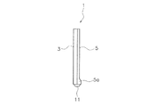
(2−2)支持部材
図4〜図7を用いて、支持部材11を詳細に説明する。図4〜図6は、支持部材及びその周辺の断面図である。図7は、ヒンジ機構及び支持部材の模式的部分平面図である。
支持部材11は、支持本体13を有している。支持本体13は、細長く延びる部材であり、上側の平坦支持面13aと、下側の湾曲面13bとを有している。湾曲面13bは、回動連結部9の回動軸が延びる方向に見て、回動連結部9の回動中心Cを中心とする円弧の一部に対応する第1湾曲面13c及び第2湾曲面13dを有している。
(2-2) Support Member The
The
第1筐体3及び第2筐体5は、内側端3a及び内側端5aを有しており、これらが支持本体13の湾曲面13bを覆うように配置されている。具体的には、図4に示すように、内側端3a及び内側端5aは、上方に開いて支持本体13の下部を収納する凹みを確保している。
内側端3a及び内側端5aは、第1湾曲面13c及び第2湾曲面13dそれぞれを相補的に支持する第3湾曲面3b及び第4湾曲面5bを有している。
The
The
支持部材11は、支持本体13の両端に設けられた一対の係止部材15を有している。一対の係止部材15は、一対のヒンジ9a、9bの長辺延び方向内側に近接して配置されている。係止部材15は、図4及び図7に示すように、第1筐体3側に形成された第1溝15aを有している。第1溝15aは、第1筐体3側を向いた鉛直面を構成する第1壁面15bを有している。係止部材15は、図7に示すように、第2筐体5側に形成された第2溝15cを有している。第2溝15cは、第2筐体5側を向いた鉛直面を構成する第2壁面15dを有している。第1筐体3及び第2筐体5は、それぞれ、第3当接部3e及び第4当接部5eを有している。第3当接部3e及び第4当接部5eは、フレキシブルディスプレイ7が開き状態において、第1壁面15bと第2壁面15dに対して回動方向に離れて配置されている。
フレキシブルディスプレイ7が閉じた状態になると、第3当接部3e及び第4当接部5eが第1壁面15b及び第2壁面15dにそれぞれ当接する。これにより、支持部材11は、第1筐体3及び第2筐体5によって回動方向に挟み付けられることになり、そのため、第1筐体3及び第2筐体5に対して回動方向に固定される。
なお、図4に示すように、回動連結部9の回動軸が延びる方向(長辺延び方向に一致)に見て、回動連結部9の回動中心C(つまり、第1筐体3及び第2筐体5の折り畳み動作の中心)は、支持部材11の平坦支持面13aに一致している。
The
When the
As shown in FIG. 4, the rotation center C of the rotation connection portion 9 (that is, the first housing) is viewed in the direction in which the rotation shaft of the rotation connection portion 9 extends (corresponds to the extension direction of the long side). The center of the folding operation of the third and the second housing 5) coincides with the
(2−3)フレキシブルディスプレイ
フレキシブルディスプレイ7の非接着部7cは、フレキシブルディスプレイ7が折り曲げられた状態になると、図6に示すように、平坦支持面13aから離れた位置で屈曲する。このように非接着部7cの曲率半径が大きな状態になるので、張力が低減する。したがって、第1筐体3と第2筐体5の折り曲げ回数が増えても、フレキシブルディスプレイ7の屈曲部に損傷や劣化が生じにくい。
(2-3) Flexible Display The
(3)開閉動作
図4では、第1筐体3と第2筐体5は所定の一方向に延びて開いた状態になっており、フレキシブルディスプレイ7も所定の一方向に延びて平面形状になっている。具体的には、フレキシブルディスプレイ7の非接着部7cは、支持本体13の平坦支持面13aによって下方から支持されている。このとき、第1筐体3の内側端3aと第2筐体5の内側端5aは互いに配列方向に当接しており、したがって第1筐体3と第2筐体5はそれ以上開かないようになっている。また、内側端3aと内側端5aによって、支持部材11は、覆われており、つまり下方に露出していない。
(3) Opening / Closing Operation In FIG. 4, the
図5では、第1筐体3と第2筐体5は折り曲げ途中状態になっており、第3湾曲面3bが第1湾曲面13cに摺動しており、第4湾曲面5bが第2湾曲面13dに摺動している。このように第1筐体3と第2筐体5は、開閉動作中には支持部材11の湾曲面13bによって回動方向に案内される。したがって、第1筐体3と第2筐体5の開閉動作が安定する。
このとき、フレキシブルディスプレイ7の非接着部7cは、支持本体13の平坦支持面13aから上方に離れて屈曲している。
In FIG. 5, the
At this time, the
図6では、第1筐体3と第2筐体5が閉じられた折り畳み状態になっている。具体的には、フレキシブルディスプレイ7の非接着部7cは、支持部材11の支持本体13の平坦支持面13aから上方に離れて屈曲している。
In FIG. 6, the
(4)第1変形例
図8〜図10を用いて、第1実施形態の変形例として、第1変形例を説明する。図8は、第1変形例の携帯端末(開いた平面状態)の模式的側面図である。図9は、第1変形例の携帯端末(折り畳み途中状態)の模式的側面図である。図10は、第1変形例の携帯端末(折り畳み状態)の模式的側面図である。
なお、以下の第1〜第6変形例の基本的構造は第1実施形態と同じである。したがって、共通点は簡略化又は省略する。
(4) First Modified Example With reference to FIGS. 8 to 10, a first modified example will be described as a modified example of the first embodiment. FIG. 8 is a schematic side view of the mobile terminal (open flat state) of the first modification. FIG. 9 is a schematic side view of the mobile terminal (in the middle of folding) of the first modification. FIG. 10 is a schematic side view of the mobile terminal (folded state) of the first modification.
The basic structure of the following first to sixth modifications is the same as that of the first embodiment. Therefore, the common points will be simplified or omitted.
第1変形例では、第1筐体3と第2筐体5を折り畳んだ状態で、支持部材11を回動不能にする構造を説明する。
図8において、携帯端末1Aは、開いた使用状態である。
支持部材11は、配列方向両側に突出する第1支持部材爪部21及び第2支持部材爪部22を上部側方に有している。さらに、第1筐体3は、第2筐体5側の下部において上方に突出する第1筐体爪部23を有している。第2筐体5は、第1筐体3側の下部において上方に突出する第2筐体爪部24を有している。
In the first modification, a structure that makes the
In FIG. 8, the
The
図9に示すように、携帯端末1Aが折り畳まれていくと、第1筐体爪部23が第1支持部材爪部21に下方から接近し、第2筐体爪部24が第2支持部材爪部22に下方から接近する。
図10に示すように、携帯端末1Aが折り畳まれると、第1筐体爪部23が第1支持部材爪部21に下方に当接し、第2筐体爪部24が第2支持部材爪部22に下方から接近する。この結果、支持部材11は、第1筐体3及び第2筐体5に対して回動不能になる。
As shown in FIG. 9, as the
As shown in FIG. 10, when the
(5)第2変形例
図11〜図13を用いて、第1実施形態の変形例として、第2変形例を説明する。図11は、第2変形例の携帯端末(開いた平面状態)の模式的側面図である。図12は、第2変形例の携帯端末(折り畳み途中状態)の模式的側面図である。図13は、第2変形例の携帯端末(折り畳み状態)の模式的側面図である。
(5) Second Modified Example With reference to FIGS. 11 to 13, a second modified example will be described as a modified example of the first embodiment. FIG. 11 is a schematic side view of the mobile terminal (open flat state) of the second modification. FIG. 12 is a schematic side view of the mobile terminal (in the middle of folding) of the second modification. FIG. 13 is a schematic side view of the mobile terminal (folded state) of the second modification.
第2変形例では、第1筐体3と第2筐体5を折り畳んだ状態で、支持部材11を作業者が触れられなくする構造を説明する。
図11において、携帯端末1Bは、開いた使用状態である。
携帯端末1Bは、プレート部材26(第1弾性覆い部材の一例)を有している。プレート部材26は、第1筐体3と第2筐体5が開き状態から閉じ状態に移行するとき及び閉じ状態において、支持部材11の外側(図下側)を覆う部材である。
In the second modification, a structure will be described in which the
In FIG. 11, the
The
具体的には、第1筐体3は、下部において、配列方向に延びて第2筐体5側に開口する凹部25を有している。凹部25は、長辺延び方向にも長く形成されている。
Specifically, the
凹部25には、プレート部材26が移動可能に配置されている。プレート部材26は、配列方向及び長辺延び方向に延びる矩形状の部材である。プレート部材26の第2筐体5側端部は、第2筐体5に固定されている。プレート部材26はフレキシブルな性質を有している。
A
図12に示すように、携帯端末1Bが折り畳まれていくと、プレート部材26が凹部25から引き出されていく。このとき、プレート部材26は、湾曲した形状になって支持部材11の下部を覆っている。
図13に示すように、携帯端末1Bが折り畳まれると、プレート部材26が湾曲した形状になって支持部材11の下部を覆った状態になる。この結果、使用者が支持部材11を触ることがない。
As shown in FIG. 12, as the
As shown in FIG. 13, when the
(6)第3変形例
図14〜図16を用いて、第1実施形態の変形例として、第3変形例を説明する。図14は、第3変形例の携帯端末(開いた平面状態)の模式的側面図である。図15は、第3変形例の携帯端末(折り畳み途中状態)の模式的側面図である。図16は、第3変形例の携帯端末(折り畳み途中状態)の模式的側面図である。
(6) Third Modified Example With reference to FIGS. 14 to 16, a third modified example will be described as a modified example of the first embodiment. FIG. 14 is a schematic side view of the mobile terminal (open flat state) of the third modification. FIG. 15 is a schematic side view of the mobile terminal (in the middle of folding) of the third modification. FIG. 16 is a schematic side view of the mobile terminal (in the middle of folding) of the third modification.
第3変形例では、第1筐体3と第2筐体5を折り畳んだ状態で、支持部材11を回動不能にする構造を説明する。
図14において、携帯端末1Cは、開いた使用状態である。
支持部材11の係止部材15には、ねじりバネ31の巻部31aが固定されている。ねじりバネ31は、両端31b、31cがそれぞれ第1筐体3と第2筐体5に固定されている。
In the third modification, a structure that makes the
In FIG. 14, the
The winding
図15に示すように、携帯端末1Cが折り畳まれていくと、ねじりバネ31が変形していく。
図16に示すように、携帯端末1Cが折り畳まれると、ねじりバネ31がさらに変形する。この状態において、ねじりバネ31によって、支持部材11は、第1筐体3及び第2筐体5に対して回動不能になる。
As shown in FIG. 15, as the
As shown in FIG. 16, when the
(7)第4変形例
図17を用いて、第1実施形態の変形例として、第4変形例を説明する。図17は、第4変形例の携帯端末(折り畳み途中状態)の模式的側面図である。
(7) Fourth Modified Example With reference to FIG. 17, a fourth modified example will be described as a modified example of the first embodiment. FIG. 17 is a schematic side view of the mobile terminal (in the middle of folding) of the fourth modification.
第4変形例では、第1筐体3と第2筐体5を折り畳んだ状態又は開いた状態で、その姿勢を維持できる構造を説明する。
図17において、携帯端末1Dは、折り畳み途中の状態である。
第1筐体3の配列方向外側の主面には、第1磁石32が設けられている。第2筐体5の配列方向外側の主面には、第2磁石33が設けられている。携帯端末1Dが折り畳まれると、第1磁石32と第2磁石33が当接することで、携帯端末1Dの折り畳み状態が維持される。なお、磁石の一方は強磁性体であってもよい。
In the fourth modification, a structure capable of maintaining the posture of the
In FIG. 17, the
A
第1筐体3の配列方向内側の先端には、第3磁石34が設けられている。第2筐体5の配列方向内側の先端には、第4磁石35が設けられている。携帯端末1Dが開かれると、第3磁石34と第4磁石35が当接することで、携帯端末1Dの平面状態が維持される。なお、磁石の一方は強磁性体であってもよい。
なお、磁石を用いた第1筐体3及び第2筐体5の固定は、折り畳み状態及び開き状態の一方にのみ用いられてもよい。
A
The fixing of the
(8)第5変形例
図18を用いて、第1実施形態の変形例として、第5変形例を説明する。図18は、第5変形例の携帯端末(折り畳み途中状態)の模式的側面図である。
(8) Fifth Modified Example With reference to FIG. 18, a fifth modified example will be described as a modified example of the first embodiment. FIG. 18 is a schematic side view of the mobile terminal (in the middle of folding) of the fifth modification.
第5変形例では、第1筐体3と第2筐体5を折り畳んだ状態又は開いた状態で、その姿勢を維持できる構造を説明する。
図18において、携帯端末1Eは、折り畳み途中の状態である。
In the fifth modification, a structure capable of maintaining the posture of the
In FIG. 18, the
回動連結部9のヒンジ機構37は、第1回動部材38と第2回動部材39とを有している。第1回動部材38は、バネ(図示せず)の力で付勢された状態のプランジャ40を有している。第2回動部材39は、回動方向に180度離れた位置にある一対の溝41(一方のみを図示)を有している。
プランジャ40が溝41内に入ると、回動させるようとする力が所定以下であれば、第1回動部材38と第2回動部材39は互いに対して回動しない。したがって、第1筐体3と第2筐体5の折り畳み状態及び開き状態が各々維持される。
The
When the
(9)第6変形例
図19〜図21を用いて、第1実施形態の変形例として、第6変形例を説明する。図19は、第6変形例の携帯端末(開いた平面状態)の模式的側面図である。図20は、第6変形例の携帯端末(折り畳み途中状態)の模式的側面図である。図21は、第6変形例の携帯端末(折り畳み状態)の模式的側面図である。
(9) Sixth Deformation Example A sixth modification will be described as a modification of the first embodiment with reference to FIGS. 19 to 21. FIG. 19 is a schematic side view of the mobile terminal (open flat state) of the sixth modification. FIG. 20 is a schematic side view of the mobile terminal (in the middle of folding) of the sixth modification. FIG. 21 is a schematic side view of the mobile terminal (folded state) of the sixth modification.
第6変形例では、携帯端末の厚みを減らせる構造を説明する。
図19において、携帯端末1Fは、開いた使用状態である。
第1筐体3Aは、第2筐体5A側において長辺延び方向両端が第2筐体5Aに向かって延びて回動自在に連結されており、配列方向内側長辺は、第2筐体5Aの配列方向内側長辺から並び方向に離れて配置されている。
携帯端末1Fは、蛇腹部材45(移動支持部材、第2弾性覆い部材の一例)を有している。蛇腹部材45は、第2筐体5Aの第2筐体側長辺に配置されている。蛇腹部材45は、第1筐体3Aと第2筐体5Aが開き状態にあるときにフレキシブルディスプレイ7の非接着部7cを支持しており、第1筐体3Aと第2筐体5Aが開き状態から閉じ状態に移行するとき及び閉じ状態において、屈曲する非接着部7cの外側を湾曲した状態で覆う。
In the sixth modification, a structure capable of reducing the thickness of the mobile terminal will be described.
In FIG. 19, the
The
The
具体的には、蛇腹部材45は、第2筐体5Aの並び方向内側長辺からさらに第1筐体3A側に延びており、フレキシブルディスプレイ7の非接着部7cを下方から支持している。蛇腹部材45は、配列方向第1端45aが第2筐体5Aの配列方向内側端部に当接又は近接して支持されており、配列方向第2端45bが第1筐体5Bの並び方向内側長辺に当接又は近接して支持されている。
第1筐体3Aは、配列方向内側の下部において、側面視で斜めの支持面を有する支持部材46を有している。
Specifically, the
The
図20に示すように、携帯端末1Fが折り畳まれていくと、フレキシブルディスプレイ7の非接着部7cが屈曲されていく。このとき、蛇腹部材45は配列方向第2端45bが支持部材46の斜面に支持されながら、フレキシブルディスプレイ7の非接着部7cを覆った状態で湾曲されていく。
図21に示すように、携帯端末1Fが折り畳まれると、フレキシブルディスプレイ7の非接着部7cが最も屈曲された状態になり、さらに、蛇腹部材45が非接着部7cを覆った状態で維持される。このとき、蛇腹部材45の配列方向第2端45bは、支持部材46の斜面に支持される。また、このタイミングで、蛇腹部材45の配列方向第1端45aは、第2筐体5Aの配列方向内側端部から離れる。
As shown in FIG. 20, as the
As shown in FIG. 21, when the
この実施形態では、折り畳み状態において、蛇腹部材45は第1筐体3Aの厚み範囲内に入っており、携帯端末1Fの厚みを増やすことがない。また、蛇腹部材45によって、フレキシブルディスプレイ7の非接着部7cの屈曲状態を収納する空間Sが確保され、さらにその空間Sが蛇腹部材45によって覆われている。
図21に示すように空間Sに収納されることで非接着部7cの曲率半径が大きな状態になるので、張力が低減する。したがって、第1筐体3Aと第2筐体5Aの折り曲げ回数が増えても、フレキシブルディスプレイ7の屈曲部に損傷や劣化が生じにくい。
In this embodiment, in the folded state, the
As shown in FIG. 21, the
さらに、この実施形態では、第2筐体5Aの配列方向内側の裏面側には出っ張り等が設けられず、平坦な面が維持されている。
なお、蛇腹部材の代わりに、弾性変形可能な他の部材(例えば、ゴム部材)を用いてもよい。
Further, in this embodiment, the back surface side of the
Instead of the bellows member, another elastically deformable member (for example, a rubber member) may be used.
2.第2実施形態
(1)概略説明
図22〜図27を用いて、第1実施形態に係る携帯端末101(折り畳み式表示装置の一例)を説明する。図22は、第2実施形態の携帯端末(開いた平面状態)の平面図である。図23は、携帯端末(折り曲げ途中第1段階)の斜視図である。図24は、携帯端末(折り曲げ途中第1段階)の側面図である。図25は、携帯端末(折曲げ途中第2段階)の斜視図である。図26は、携帯端末(折り曲げ途中第2段階)の側面図である。図27は、携帯端末(折り畳み状態)の斜視図である。
携帯端末101は、三つ折りに(Z字状に)折り畳み可能な装置であり、例えば、スマートフォン、タブレット、携帯電話、ゲーム機、電子書籍端末である。
2. Second Embodiment (1) Schematic Description The mobile terminal 101 (an example of a foldable display device) according to the first embodiment will be described with reference to FIGS. 22 to 27. FIG. 22 is a plan view of the mobile terminal (open flat state) of the second embodiment. FIG. 23 is a perspective view of a mobile terminal (first stage during bending). FIG. 24 is a side view of the mobile terminal (first stage during bending). FIG. 25 is a perspective view of a mobile terminal (second stage during bending). FIG. 26 is a side view of the mobile terminal (second stage during bending). FIG. 27 is a perspective view of a mobile terminal (folded state).
The
携帯端末101は、第1筐体103と、第2筐体104と、第3筐体105と、フレキシブルディスプレイ107と、第1回動連結部109と、第2回動連結部111と、を備える。
第1筐体103、第2筐体104、第3筐体105は、平面視矩形の平板状部材であり、平面視においてほぼ同一の大きさを有している。第1筐体103、第2筐体104及び第3筐体105は、内部空間を有している。なお、第1筐体103と第2筐体104は長辺同士が近接しており、第2筐体104と第3筐体105は長辺同士が近接している。以下、図22において、第1筐体103、第2筐体104及び第3筐体105が並んだ方向を「配列方向」とし、例えば第1筐体103又は第3筐体105から見て第2筐体104側を「配列方向内側」とし、そこから離れる側を「配列方向外側」とする。さらに、第1筐体103、第2筐体104及び第3筐体105の長辺が延びる方向を「長辺延び方向」とする。
The
The
第1回動連結部109は、第1筐体103の配列方向内側長辺と第2筐体104の一方の長辺を連結している。これにより、第1筐体103と第2筐体104が開くことで平面状態になる開き状態(使用状態)と、第1筐体103と第2筐体104が閉じることで外側に折り曲げられた状態になる閉じ状態(収納状態)とが可能になっている。
第2回動連結部111は、第2筐体104の他方の長辺と第3筐体105の配列方向内側長辺を連結している。これにより、第2筐体104と第3筐体105が開くことで平面状態になる開き状態(使用状態)と、第2筐体104と第3筐体105が閉じることで内側に折り曲げられた状態になる閉じ状態(収納状態)とが可能になっている。
第1回動連結部109は、第1筐体103と第2筐体104の両端部に設けられた一対のヒンジを有している。第2回動連結部111は、第2筐体104と第3筐体105の両端部に設けられた一対のヒンジを有している。
The first
The second
The first
図22に示すように、携帯端末101が平面状に展開された状態(使用状態)のとき、第1筐体103、第2筐体104及び第3筐体105は、主面同士が略同一面となるように配置される。
図27に示すように、携帯端末101が折り畳み状態のとき、第1筐体103と第2筐体104は裏面同士が互いに向き合って密着し、第2筐体104と第3筐体105は主面同士が互いに向き合って密着するように配置される。
As shown in FIG. 22, when the
As shown in FIG. 27, when the
フレキシブルディスプレイ107は、シームレス(継目なし)の一枚ものであり、第1筐体103、第2筐体104及び第3筐体105の主面に対して、全体を覆うように取り付けられている。言い換えると、第1筐体103、第2筐体104及び第3筐体105は、フレキシブルディスプレイ107の裏面全体を支持するような大きさを有している。フレキシブルディスプレイ107は、例えば柔軟性の高いペーパー構造を持った有機EL等のフレキシブルディスプレイである。フレキシブルディスプレイ107は、さらに、タッチパネルを備えていてもよい。
フレキシブルディスプレイ107は、例えば第1筐体103、第2筐体104及び第3筐体105の開閉動作に追随して開かれたり折り曲げられたりする。フレキシブルディスプレイ107は、折り畳み状態では、第1筐体103と第2筐体104の間で外側に折り曲げられ、第2筐体104と第3筐体105の間で内側に折り曲げられる。
The
The
フレキシブルディスプレイ107は、第1筐体103、第2筐体104及び第3筐体105の主面を覆うように配置されている。フレキシブルディスプレイ107は、第1筐体103及び第3筐体105にそれぞれ対応しておりさらに接着された第1接着部107a及び第2接着部107bと、第2筐体104に対応しているが接着されていない非接着部107cと有している。なお、第1接着部107a及び第2接着部107bとは、フレキシブルディスプレイ107において第1筐体103及び第3筐体105にそれぞれ対応する部分の一部又は全部である。
The
(2)開閉動作
図22では、第1筐体103、第2筐体104及び第3筐体105は開いた状態になっており、フレキシブルディスプレイ107は、平面形状になっている。
(2) Opening / Closing Operation In FIG. 22, the
図23及び図24は、第1筐体103、第2筐体104及び第3筐体105は折り曲げ途中第1段階になっている。
図25及び図26では、第1筐体103、第2筐体104及び第3筐体105は折り曲げ途中第2段階になっている。
In FIGS. 23 and 24, the
In FIGS. 25 and 26, the
図27では、第1筐体103、第2筐体104及び第3筐体105が閉じられた折り畳み状態になっている。
In FIG. 27, the
(3)非接着部支持機構
図28〜図33を用いて、非接着部支持機構150を説明する。図28は、携帯端末(開いた平面状態)の平面図(フレキシブルディスプレイなし)である。図29は、携帯端末(開いた平面状態)の斜視図(フレキシブルディスプレイなし)である。図30は、携帯端末(折り曲げ途中第1段階)の斜視図(フレキシブルディスプレイなし)である。図31は、携帯端末(開いた平面状態)の模式的側面図である。図32は、携帯端末(折り曲げ途中第2段階)の模式的側面図である。図33は、携帯端末(折り畳み状態)の模式的側面図である。
図28〜図30に示すように、非接着部支持機構150は、主に、支持スライダ151と、ガイド部材153とを有している。
(3) Non-adhesive portion support mechanism The non-adhesive
As shown in FIGS. 28 to 30, the non-adhesive
支持スライダ151(移動支持部材の一例)は、非接着部107cに接着されて非接着部107cの少なくとも一部を平面状態になるように支持する部材である。支持スライダ151は、第1筐体103、第2筐体104及び第3筐体105を開閉するときに、第2筐体104内において、配列方向に移動する。
具体的には、支持スライダ151は、長辺延び方向に長く延びているプレート部材である。この構造によって、フレキシブルディスプレイ107の第2筐体104部分において支持スライダ151に支持される領域が広くなる。
The support slider 151 (an example of a moving support member) is a member that is adhered to the
Specifically, the
ガイド部材153は、第2筐体104において、支持スライダ151を第1筐体103側と第3筐体105側との間で移動可能にガイドする。そのため、支持スライダ151の移動が安定する。
具体的には、第2筐体104は、矩形の枠体104aと、枠体104a内の空間104bとを有している。空間104bは、支持スライダ151の移動を許容するための空間である。空間104b内において、ガイド部材153は、配列方向に延びる複数の細いプレート部材であり、支持スライダ151の両面の複数の溝に嵌合している。これにより、支持スライダ151は、第2筐体104から外れることなく、配列方向に移動可能である。
The
Specifically, the
非接着部支持機構150は、さらに、図28に示すように、バネ155を有している。バネ155は、第2筐体104と支持スライダ151とを連結し、第1筐体103と第2筐体104が閉じてフレキシブルディスプレイ107が外側に屈曲する閉じ状態では、支持スライダ151を第1回動連結部109側から第2回動連結部111側に向けて付勢する。したがって、フレキシブルディスプレイ107の第1回動連結部109付近でのテンションが高くなくなる。その結果、フレキシブルディスプレイ107の外曲げ部での弛みが抑えられる。
The non-adhesive
図31〜図33を用いて、さらに詳細に説明する。
図31では、第1筐体103、第2筐体104及び第3筐体105は開いた状態になっており、フレキシブルディスプレイ107は、平面形状になっている。
This will be described in more detail with reference to FIGS. 31 to 33.
In FIG. 31, the
図32では、第1筐体103、第2筐体104及び第3筐体105は折り曲げ途中段階になっている。このとき、第1回動連結部109におけるフレキシブルディスプレイ107の外側屈曲部から非接着部107cに対して引っ張る力が作用するが、バネ155が支持スライダ151及び非接着部107cを反対側に付勢しているので、フレキシブルディスプレイ107の外側屈曲部分にたるみが生じない。なお、バネは省略可能である。
In FIG. 32, the
図33では、第1筐体103、第2筐体104及び第3筐体105が閉じられた折り畳み状態になっている。この場合もフレキシブルディスプレイ107の外側屈曲部分にたるみが生じない。
In FIG. 33, the
(4)リンク機構
携帯端末101は、さらに、リンク機構131(角度調整機構の一例)を有している。リンク機構131は、第2筐体104に対する第1筐体103の角度と第3筐体105の角度が常に同じになるようにするための機構である。
リンク機構131は、第1リンク部材135aと、第2リンク部材135bを有している。第1リンク部材135a及び第2リンク部材135bは、第2筐体104に対する第1筐体103の角度と第3筐体105の角度が常に同じになるように第1筐体103と第3筐体105とを連結する。
(4) Link Mechanism The
The
具体的には、第1リンク部材135aは、一端が、第1筐体103の長辺延び方向端部において第1回動連結部109より並び方向外側の位置に対して、第1回動部137aによって連結されている。さらに、第1リンク部材135aは、他端が、第2筐体104の長辺延び方向端部において第2回動連結部111より並び方向内側の位置に対して、第2回動部139aによって連結されている。
第2リンク部材135bは、第1リンク部材135aと同じである。
リンク機構131は、連結部材141を有している。連結部材141は、第1リンク部材135aと第2リンク部材135bとを連結している。具体的には、連結部材141は、長辺延び方向に延びる細いプレートである。
Specifically, one end of the
The
The
図23〜図27に示すように、リンク機構131によって、第2筐体104に対する第1筐体103の角度と第3筐体105の角度が常に同じになっている。
したがって、フレキシブルディスプレイ7の折り畳み動作中に押し出し量と引き込み量が同じになる。その結果、フレキシブルディスプレイ7に大きな圧縮応力や引っ張り応力が発生しない。
さらに、リンク機構131によって、第1筐体103と第2筐体104、さらには第2筐体104と第3筐体105が、意図した方向にのみ折り曲げ可能になっている。
As shown in FIGS. 23 to 27, the
Therefore, the pushing amount and the pulling amount are the same during the folding operation of the
Further, the
(5)第7変形例
図34及び図35を用いて、第2実施形態の変形例として、第7変形例を説明する。図34は、一般的なフレキシブルディスプレイのたわみを示す模式的側面図である。図35は、第7変形例の携帯端末(折り畳み状態)の模式的側面図である。
なお、以下の第7〜第12変形例の基本的構造は第2実施形態と同じである。したがって、共通点は簡略化又は省略する。
第1実施形態では支持部材11によって、第2実施形態では支持スライダ151によってフレキシブルディスプレイ107の非接着部107cが支持されていた。これらの部材による支持面積を減らす又は支持自体をなくすことが好ましい。
(5) Seventh Deformation Example A seventh modification will be described as a modification of the second embodiment with reference to FIGS. 34 and 35. FIG. 34 is a schematic side view showing the deflection of a general flexible display. FIG. 35 is a schematic side view of the mobile terminal (folded state) of the seventh modification.
The basic structure of the following 7th to 12th modifications is the same as that of the second embodiment. Therefore, the common points will be simplified or omitted.
The
一方、上記のようにフレキシブルディスプレイ107の支持面積を減らしたり支持を無くしたりすれば、下記の問題が考えられる。図34に示すように、一般的な説明として、携帯端末181において筐体184によって支持されたフレキシブルディスプレイ187(タッチパネルを有する)が薄い場合は、下側に支持部材がなければ、図に示すように指Fの操作によってたわむことがある。その場合は、たわみによってフレキシブルディスプレイ187がダメージを受けることがある。また、外観上も好ましくない。
そこで、図35に示す第7変形例では、携帯端末101Aは、フレキシブルディスプレイをある程度厚みのある補強フィルムで挟むことで、全体の厚みを大きくしている。この場合、圧力が作用してもたわまない剛性を確保できる。
なお、フレキシブルディスプレイが回動連結部分において屈曲する際に、フレキシブルディスプレイに引っ張りや圧縮の力が作用しないように、補強フィルムは同じ厚みであることが好ましい。
On the other hand, if the support area of the
Therefore, in the seventh modification shown in FIG. 35, the
It is preferable that the reinforcing films have the same thickness so that a pulling or compressing force does not act on the flexible display when the flexible display bends at the rotationally connected portion.
具体的には、携帯端末101Aでは、第2筐体104Aの上に、フレキシブルディスプレイ161が設けられている。フレキシブルディスプレイ161の両面には、接着層162、163を介して第1補強フィルム164と第2補強フィルム165がそれぞれ接着されている。
これにより、フレキシブルディスプレイ161の下方の空間Aがあっても、指Fがフレキシブルディスプレイ161を押してもたわみが生じにくい。
この変形例は、第1実施形態でも有効である。
Specifically, in the
As a result, even if there is a space A below the
This modification is also valid in the first embodiment.
(6)第8変形例
図36〜図38を用いて、第2実施形態の変形例として、第8変形例を説明する。図36は、第8変形例の携帯端末(開いた平面状態)の模式的側面図である。図37は、第8変形例の携帯端末(折り曲げ途中第2段階)の模式的側面図である。図38は、第8変形例の携帯端末(折り畳み状態)の模式的側面図である。
この実施形態は、第2筐体104において、フレキシブルディスプレイ107の非接着部107cの下に空間ができない又は小さくなる構造である。この結果、支持スライダが不要になる。
(6) Eighth Modification Example An eighth modification will be described as a modification of the second embodiment with reference to FIGS. 36 to 38. FIG. 36 is a schematic side view of the mobile terminal (open flat state) of the eighth modification. FIG. 37 is a schematic side view of the mobile terminal (second stage during bending) of the eighth modification. FIG. 38 is a schematic side view of the mobile terminal (folded state) of the eighth modification.
This embodiment has a structure in which a space is created or becomes smaller under the
具体的には、携帯端末101Bは、第2筐体104の内部に、無端のフィルム171(移動支持部材の一例)を有している。フィルム171は、一部がフレキシブルディスプレイ107の非接着部107cの一部である固定部107dに固定されている。フィルム171、第2筐体104の内部において、非接着部107cの配列方向の移動に伴って、回転しながら移動する。
Specifically, the
図36〜図38を用いて、さらに詳細に説明する。
図36では、第1筐体103、第2筐体104及び第3筐体105は開いた状態になっており、フレキシブルディスプレイ107は、平面形状になっている。この状態では、フィルム171がフレキシブルディスプレイ107の非接着部107cを下方から支持している。
This will be described in more detail with reference to FIGS. 36 to 38.
In FIG. 36, the
図37では、第1筐体103、第2筐体104及び第3筐体105は折り曲げ途中段階になっている。このとき、フィルム171は、フレキシブルディスプレイ107の非接着部107cによって引っ張られながら、回転しつつ第2筐体104内を配列方向に移動する。
In FIG. 37, the
図38では、第1筐体103、第2筐体104及び第3筐体105が閉じられた折り畳み状態になっている。
In FIG. 38, the
(7)第9変形例
図39〜図42を用いて、第2実施形態の変形例として、第9変形例を説明する。図39は、第9変形例の携帯端末(開いた平面状態)の模式的側面図である。図40は、フレキシブルディスプレイとガイド部を示す模式的斜視図である。図41は、第9変形例の携帯端末(折り曲げ途中第2段階)の模式的側面図である。図42は、第9変形例の携帯端末(折り畳み状態)の模式的側面図である。
(7) Ninth Modification Example The ninth modification will be described as a modification of the second embodiment with reference to FIGS. 39 to 42. FIG. 39 is a schematic side view of the mobile terminal (open flat state) of the ninth modification. FIG. 40 is a schematic perspective view showing a flexible display and a guide unit. FIG. 41 is a schematic side view of the mobile terminal (second stage during bending) of the ninth modification. FIG. 42 is a schematic side view of the mobile terminal (folded state) of the ninth modification.
携帯端末101Cは、図39及び図40に示すように、ガイド部172を有している。ガイド部172は、第2筐体104に設けられている。具体的には、ガイド部172は、第2筐体104の長辺延び方向両端に第1ガイド部172a及び第2ガイド部172bとして設けられ、フレキシブルディスプレイ107の非接着部107cを配列方向にガイドしている。さらに具体的には、ガイド部172は、非接着部107cの長辺延び方向両端の上側を覆っている。
As shown in FIGS. 39 and 40, the
図39〜図41を用いて、さらに詳細に説明する。
図39では、第1筐体103、第2筐体104及び第3筐体105は開いた状態になっており、フレキシブルディスプレイ107は、平面形状になっている。
図40では、第1筐体103、第2筐体104及び第3筐体105は折り曲げ途中段階になっている。このとき、フレキシブルディスプレイ107の非接着部107cはガイド部172にガイドされながら配列方向に移動する。
図41では、第1筐体103、第2筐体104及び第3筐体105が閉じられた折り畳み状態になっている。
This will be described in more detail with reference to FIGS. 39 to 41.
In FIG. 39, the
In FIG. 40, the
In FIG. 41, the
(8)第10変形例
図43〜図45を用いて、第2実施形態の変形例として、第10変形例を説明する。図43は、第10変形例の携帯端末(開いた平面状態)の模式的側面図である。図44は、第10変形例の携帯端末(折り曲げ途中第2段階)の模式的側面図である。図45は、第10変形例の携帯端末(折り畳み状態)の模式的側面図である。
(8) Tenth Deformation Example The tenth modification will be described as a modification of the second embodiment with reference to FIGS. 43 to 45. FIG. 43 is a schematic side view of the mobile terminal (open flat state) of the tenth modification. FIG. 44 is a schematic side view of the mobile terminal (second stage during bending) of the tenth modification. FIG. 45 is a schematic side view of the mobile terminal (folded state) of the tenth modification.
図43において、携帯端末101Dは、開いた使用状態である。つまり、第1筐体103A、第2筐体104A及び第3筐体105Aは開いた状態になっており、フレキシブルディスプレイ107Aは、平面形状になっている。
第3筐体105Aは、第2筐体104A側において長辺延び方向両端が第1筐体103Aに向かって延びて回動自在に連結されており、配列方向長辺は、第2筐体104Aの配列方向内側長辺から並び方向に離れて配置されている。
携帯端末101Dは、蛇腹部材145を有している。蛇腹部材145は、第2筐体104Aからさらに第3筐体105A側に延びており、フレキシブルディスプレイ107の非接着部107cを下方から支持している。蛇腹部材145は、配列方向第1端145aが第2筐体104Aの長辺に当接又は近接して支持されており、配列方向第2端145bが第3筐体105Aの並び方向内側長辺に当接又は近接して支持されている。
第3筐体105Aは、配列方向内側の下部において、側面視で斜めの支持面を有する支持部材146を有している。
In FIG. 43, the
The
The
The
図44に示すように、携帯端末101Dが折り畳まれていくと、フレキシブルディスプレイ107の非接着部107cが第2筐体104Aと第3筐体105Aとの間で屈曲されていく。このとき、蛇腹部材145は、配列方向第2端145bが支持部材146の斜面に支持されながら、フレキシブルディスプレイ107の非接着部107cの屈曲部を覆った状態で屈曲されていく。
図45に示すように、携帯端末101Dが折り畳まれると、フレキシブルディスプレイ107の非接着部107cが最も屈曲された状態になり、さらに、蛇腹部材145が非接着部7cを覆った状態で維持される。なお、蛇腹部材145の配列方向第2端145bは、支持部材146の斜面に支持される。また、このタイミングで、蛇腹部材145の配列方向第1端145aは、第2筐体105Aの長辺から離れる。
As shown in FIG. 44, as the
As shown in FIG. 45, when the
この実施形態では、折り畳み状態において、蛇腹部材145は第3筐体105Aの厚み範囲内に入っており、端末の厚みを増やすことがない。また、蛇腹部材145によって、フレキシブルディスプレイ107の非接着部107cの屈曲状態を収納する空間Sが確保され、さらにその空間が蛇腹部材145によって覆われている。
図45に示すように空間Sに収納されることで非接着部107cの曲率半径が大きな状態になるので、張力が低減する。したがって、第2筐体104Aと第3筐体105Aの折り曲げ回数が増えても、フレキシブルディスプレイ107の屈曲部に損傷や劣化が生じにくい。
In this embodiment, in the folded state, the
As shown in FIG. 45, the
さらに、この実施形態では、第2筐体104Aの配列方向内側の裏面側(図上側)には出っ張り等が設けられず、平坦な面が維持されている。以上より、折り畳み時の携帯端末101Dの厚み全体を小さくできる。
なお、蛇腹部材の代わりに、弾性変形可能な他の部材(例えば、ゴム部材)を用いてもよい。
Further, in this embodiment, the back surface side (upper side in the drawing) inside the
Instead of the bellows member, another elastically deformable member (for example, a rubber member) may be used.
(9)第11変形例
図46〜図48を用いて、第2実施形態の変形例として、第11変形例を説明する。図46は、第11変形例の携帯端末(開いた平面状態)の模式的側面図である。図47は、第11変形例の携帯端末(折り曲げ途中第2段階)の模式的側面図である。図48は、第11変形例の携帯端末(折り畳み状態)の模式的側面図である。
携帯端末101Eは、無端のベルト173(角度調整機構の一例)を有している。ベルト173は、第1ヒンジ119A及び第2ヒンジ119Bに掛け回されている。第1ヒンジ119Aは、第1筐体103に回動不能に連結された部材である。第2ヒンジ119Bは、第3筐体105に回動不能に連結された部材である。
ベルト173によって、第1ヒンジ119A及び第2ヒンジ119Bの回動角度(つまり、第2筐体104に対する第1筐体103及び第3筐体105の角度)が同じになるように合わされる。これにより、フレキシブルディスプレイ107の折り畳み動作中に押し出し量と引き込み量が同じになる。その結果、フレキシブルディスプレイ107に大きな圧縮応力や引っ張り応力が発生しない。
(9) Eleventh Deformation Example An eleventh modification will be described as a modification of the second embodiment with reference to FIGS. 46 to 48. FIG. 46 is a schematic side view of the mobile terminal (open flat state) of the eleventh modification. FIG. 47 is a schematic side view of the mobile terminal (second stage during bending) of the eleventh modification. FIG. 48 is a schematic side view of the mobile terminal (folded state) of the eleventh modification.
The
The
図46〜図48を用いて、さらに詳細に説明する。
図46では、第1筐体103、第2筐体104及び第3筐体105は開いた状態になっており、フレキシブルディスプレイ107は、平面形状になっている。
図47では、第1筐体103、第2筐体104及び第3筐体105は折り曲げ途中段階になっている。ベルト173によって第2筐体104に対する第1筐体103及び第3筐体105の角度が同じになるように合わされる。これにより、フレキシブルディスプレイ107の折り畳み動作中に押し出し量と引き込み量が同じになる。
図48では、第1筐体103、第2筐体104及び第3筐体105が閉じられた折り畳み状態になっている。
It will be described in more detail with reference to FIGS. 46 to 48.
In FIG. 46, the
In FIG. 47, the
In FIG. 48, the
(10)第12変形例
図49〜図51を用いて、第2実施形態の変形例として、第12変形例を説明する。図49は、第12変形例の携帯端末(開いた平面状態)の模式的側面図である。図50は、第12変形例の携帯端末(折り曲げ途中第2段階)の模式的側面図である。図51は、第12変形例の携帯端末(折り畳み状態)の模式的側面図である。
(10) 12th Deformation Example A 12th modification will be described as a modification of the second embodiment with reference to FIGS. 49 to 51. FIG. 49 is a schematic side view of the mobile terminal (open flat state) of the twelfth modification. FIG. 50 is a schematic side view of the mobile terminal (second stage during bending) of the twelfth modification. FIG. 51 is a schematic side view of the mobile terminal (folded state) of the twelfth modified example.
携帯端末101Fは、第2筐体104の側方に、配列方向に並んだ複数の歯車174(角度調整機構の一例)を有している。複数の歯車174は互いに噛み合っており、両端の歯車174は、第1ヒンジ175A及び第2ヒンジ175Bに設けられた歯車に噛み合っている。第1ヒンジ175Aは、第1筐体103に回動不能に連結された部材である。第2ヒンジ175Bは、第3筐体105に回動不能に連結された部材である。
複数の歯車174によって、第1ヒンジ175A及び第2ヒンジ175Bの回転角度(つまり、第2筐体104に対する第1筐体103及び第3筐体105の角度)が同じになるように合わされる。これにより、フレキシブルディスプレイ107の折り畳み動作中に押し出し量と引き込み量が同じになる。その結果、フレキシブルディスプレイ107に大きな圧縮応力や引っ張り応力が発生しない。
The
The plurality of
図49〜図51を用いて、さらに詳細に説明する。
図49では、第1筐体103、第2筐体104及び第3筐体105は開いた状態になっており、フレキシブルディスプレイ107は、平面形状になっている。
図50では、第1筐体103、第2筐体104及び第3筐体105は折り曲げ途中段階になっている。複数の歯車174によって第2筐体104に対する第1筐体103及び第3筐体105の角度が同じになるように合わされる。これにより、フレキシブルディスプレイ107の折り畳み動作中に押し出し量と引き込み量が同じになる。
図51では、第1筐体103、第2筐体104及び第3筐体105が閉じられた折り畳み状態になっている。
This will be described in more detail with reference to FIGS. 49 to 51.
In FIG. 49, the
In FIG. 50, the
In FIG. 51, the
3.他の実施形態
以上、本発明の複数の実施形態について説明したが、本発明は上記実施形態に限定されるものではなく、発明の要旨を逸脱しない範囲で種々の変更が可能である。特に、本明細書に書かれた複数の実施形態及び変形例は必要に応じて任意に組み合せ可能である。
3. 3. Other Embodiments Although the plurality of embodiments of the present invention have been described above, the present invention is not limited to the above embodiments, and various modifications can be made without departing from the gist of the invention. In particular, the plurality of embodiments and modifications described herein can be arbitrarily combined as needed.
本発明は、折り畳み式表示装置に広く適用できる。 The present invention can be widely applied to a foldable display device.
1 :携帯端末
3 :第1筐体
5 :第2筐体
7 :フレキシブルディスプレイ
7a :接着部
7b :接着部
7c :非接着部
9 :回動連結部
9a :ヒンジ
9b :ヒンジ
11 :支持部材
13 :支持本体
13a :平坦支持面
13b :湾曲面
15 :係止部材
1: Mobile terminal 3: First housing 5: Second housing 7:
Claims (11)
第1筐体と、
第2筐体と、
前記第1筐体と前記第2筐体が開くことで平面状態になる開き状態と、前記第1筐体と前記第2筐体が閉じることで内側に折り曲げられた状態になる閉じ状態とが可能になるように、前記第1筐体と前記第2筐体とを連結している回動連結部と、
前記第1筐体及び前記第2筐体の一面を覆うように配置されたフレキシブルなディスプレイと、
前記第1筐体と前記第2筐体との間に配置され、前記ディスプレイが開き状態になるときに前記ディスプレイを支持する平坦支持面を有する支持部材と、を備え、
前記ディスプレイは、前記第1筐体及び前記第2筐体に接着された接着部と、前記第1筐体と前記第2筐体との間で前記支持部材の前記平坦支持面から離れることができる非接着部とを有し、
前記ディスプレイの前記非接着部は、前記ディスプレイが閉じ状態になると、前記平坦支持面から上方に離れて屈曲する、折り畳み式表示装置。 A foldable display device in which multiple housings are foldably connected.
With the first housing
With the second housing
There are two types: an open state in which the first housing and the second housing open to form a flat state, and a closed state in which the first housing and the second housing close to form an inwardly bent state. A rotary connecting portion that connects the first housing and the second housing so as to be possible.
A flexible display arranged so as to cover one surface of the first housing and the second housing,
A support member arranged between the first housing and the second housing and having a flat support surface for supporting the display when the display is opened is provided.
The display may be separated from the flat support surface of the support member between the first housing and the adhesive portion bonded to the second housing, and the first housing and the second housing. can have a and a non-adhesive portion,
A foldable display device in which the non-adhesive portion of the display bends upward away from the flat support surface when the display is closed.
前記第1筐体及び前記第2筐体は、各々、前記第1湾曲面及び前記第2湾曲面を相補的に支持する第3湾曲面及び第4湾曲面を有している、請求項1に記載の折り畳み式表示装置。 The support member has a first curved surface and a second curved surface corresponding to a part of an arc centered on the rotation center of the rotation connecting portion when viewed in the direction in which the rotation axis of the rotation connecting portion extends. Have and
Said first housing and said second housing, respectively, and a third curved surface and a fourth curved surface complementary supporting said first curved surface and the second curved surface, according to claim 1 foldable display device according to.
第1筐体と、
第2筐体と、
前記第1筐体と前記第2筐体が開くことで平面状態になる開き状態と、前記第1筐体と前記第2筐体が閉じることで内側に折り曲げられた状態になる閉じ状態とが可能になるように、前記第1筐体と前記第2筐体とを連結している回動連結部と、
前記第1筐体及び前記第2筐体の一面を覆うように配置されたフレキシブルなディスプレイと、
前記第1筐体と前記第2筐体との間に配置され、前記ディスプレイが開き状態になるときに前記ディスプレイを支持する平坦支持面を有する支持部材と、を備え、
前記ディスプレイは、前記第1筐体及び前記第2筐体に接着された接着部と、前記第1筐体と前記第2筐体との間で前記支持部材の前記平坦支持面から離れることができる非接着部とを有し、
前記支持部材は、前記回動連結部の回動軸が延びる方向に見て、前記回動連結部の回動中心を中心とする円弧の一部に対応する第1湾曲面及び第2湾曲面を有しており、
前記第1筐体及び前記第2筐体は、各々、前記第1湾曲面及び前記第2湾曲面を相補的に支持する第3湾曲面及び第4湾曲面を有している、折り畳み式表示装置。 A foldable display device in which multiple housings are foldably connected.
With the first housing
With the second housing
There are two types: an open state in which the first housing and the second housing open to form a flat state, and a closed state in which the first housing and the second housing close to form an inwardly bent state. A rotary connecting portion that connects the first housing and the second housing so as to be possible.
A flexible display arranged so as to cover one surface of the first housing and the second housing,
A support member arranged between the first housing and the second housing and having a flat support surface for supporting the display when the display is opened is provided.
The display may be separated from the flat support surface of the support member between the first housing and the adhesive portion bonded to the second housing, and the first housing and the second housing. Has a non-adhesive part that can
The support member has a first curved surface and a second curved surface corresponding to a part of an arc centered on the rotation center of the rotation connecting portion when viewed in the direction in which the rotation axis of the rotation connecting portion extends. Have and
Said first housing and said second housing, respectively, and a third curved surface and a fourth curved surface complementary supporting said first curved surface and the second curved surface, folding Ritatami Expression display device.
前記第1筐体及び前記第2筐体は、それぞれ、前記ディスプレイが開き状態で前記第1当接部と前記第2当接部に対して回転方向に離れており、前記ディスプレイが閉じ状態になると、前記第1当接部と前記第2当接部にそれぞれ当接する第3当接部及び第4当接部を有する、請求項1〜3のいずれかに記載の折り畳み式表示装置。 The support member has a first contact portion facing the first housing side and a second contact portion facing the second housing side.
The first housing and the second housing are separated from each other in the rotational direction with respect to the first contact portion and the second contact portion in the open state of the display, respectively, and the display is in the closed state. The foldable display device according to any one of claims 1 to 3, further comprising a third contact portion and a fourth contact portion that contact the first contact portion and the second contact portion, respectively.
第1筐体と、
第2筐体と、
第3筐体と、
前記第1筐体、前記第2筐体及び前記第3筐体の一面を覆うように配置され、前記第1筐体及び前記第3筐体の主要部にそれぞれ接着された第1接着部及び第2接着部と、前記第1接着部と前記第2接着部との間で前記第1筐体、前記第2筐体及び前記第3筐体に対して離れることができる非接着部とを有するフレキシブルなディスプレイと、
前記第1筐体と前記第2筐体が開いて前記ディスプレイが平面状態になる開き状態と、前記第1筐体と前記第2筐体が閉じて前記ディスプレイが外側に折り曲げられた状態になる閉じ状態とが可能になるように、前記第1筐体と前記第2筐体とを連結している第1回動連結部と、
前記第2筐体と前記第3筐体が開いて前記ディスプレイが平面状態になる開き状態と、前記第2筐体と前記第3筐体が閉じて前記ディスプレイが内側に折り曲げられた状態になる閉じ状態とが可能になるように、前記第2筐体と前記第3筐体とを連結している第2回動連結部と、
前記第2筐体内において前記第1筐体側と前記第3筐体側とに移動可能に配置され、前記非接着部に接着されて前記非接着部の少なくとも一部を平面状態になるように支持する移動支持部材と、
を備えた折り畳み式表示装置。 A foldable display device in which multiple housings are foldably connected.
With the first housing
With the second housing
With the third housing
A first adhesive portion and a first adhesive portion arranged so as to cover one surface of the first housing, the second housing, and the third housing, and adhered to the main parts of the first housing and the third housing, respectively. A second adhesive portion and a non-adhesive portion that can be separated from the first housing, the second housing, and the third housing between the first adhesive portion and the second adhesive portion. With a flexible display
The first housing and the second housing are opened and the display is in a flat state, and the first housing and the second housing are closed and the display is bent outward. A first rotation connecting portion that connects the first housing and the second housing so that the closed state can be achieved.
The second housing and the third housing are opened and the display is in a flat state, and the second housing and the third housing are closed and the display is bent inward. A second rotation connecting portion that connects the second housing and the third housing so that the closed state can be achieved.
It is movably arranged between the first housing side and the third housing side in the second housing, and is adhered to the non-adhesive portion to support at least a part of the non-adhesive portion so as to be in a flat state. With the moving support member,
Foldable display device with.
前記第2筐体と前記支持スライダとを連結し、前記第1筐体と前記第2筐体が閉じて前記ディスプレイが外側に屈曲する閉じ状態では、前記支持スライダを前記第1回動連結部側から前記第2回動連結部側に向けて付勢する付勢部材をさらに備えた、請求項7に記載の折り畳み式表示装置。 The moving support member is a support slider.
Wherein the second housing and connecting the support slider, wherein in the closed state the first housing second the housing is closed the display is bent outward, the support slider the first pivotal connecting portion The foldable display device according to claim 7, further comprising an urging member for urging from the side toward the second rotation connecting portion side.
Priority Applications (7)
| Application Number | Priority Date | Filing Date | Title |
|---|---|---|---|
| JP2018248516A JP6917973B2 (en) | 2018-12-28 | 2018-12-28 | Folding display device |
| US17/418,516 US20220083102A1 (en) | 2018-12-28 | 2019-11-22 | Foldable display device |
| KR1020217014422A KR20210106413A (en) | 2018-12-28 | 2019-11-22 | foldable display |
| EP19901759.1A EP3879799B1 (en) | 2018-12-28 | 2019-11-22 | Folding display device |
| CN201980085124.5A CN113228602B (en) | 2018-12-28 | 2019-11-22 | Folding display device |
| PCT/JP2019/045823 WO2020137288A1 (en) | 2018-12-28 | 2019-11-22 | Folding display device |
| TW108143039A TWI812817B (en) | 2018-12-28 | 2019-11-27 | folding display device |
Applications Claiming Priority (1)
| Application Number | Priority Date | Filing Date | Title |
|---|---|---|---|
| JP2018248516A JP6917973B2 (en) | 2018-12-28 | 2018-12-28 | Folding display device |
Publications (2)
| Publication Number | Publication Date |
|---|---|
| JP2020106776A JP2020106776A (en) | 2020-07-09 |
| JP6917973B2 true JP6917973B2 (en) | 2021-08-11 |
Family
ID=71129012
Family Applications (1)
| Application Number | Title | Priority Date | Filing Date |
|---|---|---|---|
| JP2018248516A Active JP6917973B2 (en) | 2018-12-28 | 2018-12-28 | Folding display device |
Country Status (7)
| Country | Link |
|---|---|
| US (1) | US20220083102A1 (en) |
| EP (1) | EP3879799B1 (en) |
| JP (1) | JP6917973B2 (en) |
| KR (1) | KR20210106413A (en) |
| CN (1) | CN113228602B (en) |
| TW (1) | TWI812817B (en) |
| WO (1) | WO2020137288A1 (en) |
Families Citing this family (7)
| Publication number | Priority date | Publication date | Assignee | Title |
|---|---|---|---|---|
| KR20200131662A (en) | 2019-05-14 | 2020-11-24 | 삼성전자주식회사 | Multi foldable electronic device |
| KR20210068722A (en) * | 2019-12-02 | 2021-06-10 | 엘지디스플레이 주식회사 | Foldable display device |
| CN114005357B (en) * | 2020-07-28 | 2023-07-14 | 华为技术有限公司 | Screen supporting device and electronic equipment |
| CN112071204B (en) * | 2020-09-11 | 2022-10-18 | 维沃移动通信有限公司 | Electronic device |
| CN112885023B (en) * | 2021-02-28 | 2022-05-24 | 北京清尚建筑设计研究院有限公司 | Building control system with automatic integrated management function and use method thereof |
| CN115695597A (en) * | 2021-07-27 | 2023-02-03 | 北京小米移动软件有限公司 | Folding screen and electronic equipment |
| KR20230024521A (en) | 2021-08-12 | 2023-02-21 | 주식회사 엘지에너지솔루션 | Negative electrode for lithium secondary battery and manufacturing method thereof |
Family Cites Families (20)
| Publication number | Priority date | Publication date | Assignee | Title |
|---|---|---|---|---|
| US6577496B1 (en) * | 2001-01-18 | 2003-06-10 | Palm, Inc. | Non-rigid mounting of a foldable display |
| JP2008106852A (en) * | 2006-10-25 | 2008-05-08 | Sugatsune Ind Co Ltd | Hinge device and portable telephone |
| US20140123436A1 (en) * | 2012-11-02 | 2014-05-08 | Research In Motion Limited | Support for a flexible display |
| WO2013080191A2 (en) * | 2013-02-22 | 2013-06-06 | Wasfi Alshdaifat | Foldable flexible display (tri-phone) |
| KR102020659B1 (en) * | 2013-06-03 | 2019-09-11 | 삼성디스플레이 주식회사 | Foldable display device |
| US9395070B2 (en) * | 2013-07-19 | 2016-07-19 | Semiconductor Energy Laboratory Co., Ltd. | Support of flexible component and light-emitting device |
| KR20200139848A (en) * | 2013-08-30 | 2020-12-14 | 가부시키가이샤 한도오따이 에네루기 켄큐쇼 | Display device |
| KR101875855B1 (en) * | 2014-02-17 | 2018-07-06 | 삼성전자주식회사 | Hinge apparatus and foldable display apparatus having the same |
| KR101727971B1 (en) | 2014-02-21 | 2017-04-18 | 삼성전자주식회사 | Foldable device |
| JP6425114B2 (en) * | 2014-07-02 | 2018-11-21 | Tianma Japan株式会社 | Foldable display device and electric device |
| US9541962B2 (en) * | 2014-10-16 | 2017-01-10 | Microsoft Technology Licensing, Llc | Mobile computing device having a flexible hinge structure |
| KR20160089164A (en) * | 2015-01-19 | 2016-07-27 | 삼성전자주식회사 | Flexible device and method for controlling shape of display thereof |
| KR102366516B1 (en) * | 2015-08-31 | 2022-02-22 | 엘지디스플레이 주식회사 | Foldable display apparatus |
| JP6510057B2 (en) * | 2015-09-24 | 2019-05-08 | シャープ株式会社 | Flexible device |
| JP6639313B2 (en) * | 2016-04-08 | 2020-02-05 | 株式会社Nttドコモ | Mobile terminal |
| JP2017192659A (en) * | 2016-04-22 | 2017-10-26 | 株式会社ナチュラレーザ・ワン | Wearable band and electronic apparatus with wearable band attached thereto |
| JP6429909B2 (en) * | 2017-01-10 | 2018-11-28 | レノボ・シンガポール・プライベート・リミテッド | Portable information equipment |
| JP2020522730A (en) * | 2017-05-19 | 2020-07-30 | イー インク コーポレイション | Foldable electro-optical display including digitization and touch sensing |
| US10110717B1 (en) * | 2018-01-02 | 2018-10-23 | Yongbiao Liu | Smartphone with flexible folding screen |
| CN108415511A (en) * | 2018-02-27 | 2018-08-17 | 努比亚技术有限公司 | Folding mobile terminal |
-
2018
- 2018-12-28 JP JP2018248516A patent/JP6917973B2/en active Active
-
2019
- 2019-11-22 WO PCT/JP2019/045823 patent/WO2020137288A1/en unknown
- 2019-11-22 CN CN201980085124.5A patent/CN113228602B/en active Active
- 2019-11-22 KR KR1020217014422A patent/KR20210106413A/en not_active Application Discontinuation
- 2019-11-22 US US17/418,516 patent/US20220083102A1/en active Pending
- 2019-11-22 EP EP19901759.1A patent/EP3879799B1/en active Active
- 2019-11-27 TW TW108143039A patent/TWI812817B/en active
Also Published As
| Publication number | Publication date |
|---|---|
| EP3879799A4 (en) | 2022-02-16 |
| JP2020106776A (en) | 2020-07-09 |
| EP3879799B1 (en) | 2023-08-23 |
| US20220083102A1 (en) | 2022-03-17 |
| CN113228602B (en) | 2023-11-21 |
| TW202032317A (en) | 2020-09-01 |
| TWI812817B (en) | 2023-08-21 |
| EP3879799A1 (en) | 2021-09-15 |
| CN113228602A (en) | 2021-08-06 |
| WO2020137288A1 (en) | 2020-07-02 |
| KR20210106413A (en) | 2021-08-30 |
Similar Documents
| Publication | Publication Date | Title |
|---|---|---|
| JP6917973B2 (en) | Folding display device | |
| US10104790B2 (en) | Mobile terminal | |
| US20230229189A1 (en) | Folding Apparatus and Electronic Device | |
| US7787917B2 (en) | Folding electronic device with continuous display | |
| JP5085725B2 (en) | Openable small electronic equipment | |
| JP5319825B1 (en) | Electronics | |
| KR101006815B1 (en) | Sliding type mobile terminal | |
| US20120149438A1 (en) | Mobile phone of folding type and hinge device of the same | |
| JP2010530553A (en) | Electronic device having flexible display with variable angle | |
| WO2020065936A1 (en) | Display device | |
| JP4796651B2 (en) | Two-axis slide device for portable terminal | |
| US8183459B2 (en) | Handheld electronic device and rising mechanism | |
| US11723163B1 (en) | Sliding electronic devices with translating flexible displays having rigidly coupled foldable substrates and corresponding methods | |
| US20100184492A1 (en) | Mobile phone having pop-up keypad | |
| CN114241913B (en) | Bendable display module and display device | |
| CN116434658A (en) | Foldable display device | |
| KR100827740B1 (en) | Elastic module and slide apparatus of sliding type cellular phone having the elastic module | |
| WO2020240712A1 (en) | Display device | |
| CN114911307A (en) | Flexible circuit board assembly and electronic device | |
| JP4708321B2 (en) | Sliding mobile device | |
| US11797050B2 (en) | Electronic devices with sliding device housings and translating flexible displays and corresponding methods | |
| JP4899191B2 (en) | Portable electronic devices | |
| JP5246763B2 (en) | Openable electronic device |
Legal Events
| Date | Code | Title | Description |
|---|---|---|---|
| A621 | Written request for application examination |
Free format text: JAPANESE INTERMEDIATE CODE: A621 Effective date: 20201207 |
|
| A871 | Explanation of circumstances concerning accelerated examination |
Free format text: JAPANESE INTERMEDIATE CODE: A871 Effective date: 20201207 |
|
| RD03 | Notification of appointment of power of attorney |
Free format text: JAPANESE INTERMEDIATE CODE: A7423 Effective date: 20201207 |
|
| A975 | Report on accelerated examination |
Free format text: JAPANESE INTERMEDIATE CODE: A971005 Effective date: 20210209 |
|
| A131 | Notification of reasons for refusal |
Free format text: JAPANESE INTERMEDIATE CODE: A131 Effective date: 20210302 |
|
| A521 | Request for written amendment filed |
Free format text: JAPANESE INTERMEDIATE CODE: A523 Effective date: 20210419 |
|
| TRDD | Decision of grant or rejection written | ||
| A01 | Written decision to grant a patent or to grant a registration (utility model) |
Free format text: JAPANESE INTERMEDIATE CODE: A01 Effective date: 20210706 |
|
| A61 | First payment of annual fees (during grant procedure) |
Free format text: JAPANESE INTERMEDIATE CODE: A61 Effective date: 20210720 |
|
| R150 | Certificate of patent or registration of utility model |
Ref document number: 6917973 Country of ref document: JP Free format text: JAPANESE INTERMEDIATE CODE: R150 |