JP6917809B2 - Laser machining method for metallic materials by controlling the position of the optical axis of the laser with respect to the assist gas flow, and machine and computer programs for implementing the method. - Google Patents
Laser machining method for metallic materials by controlling the position of the optical axis of the laser with respect to the assist gas flow, and machine and computer programs for implementing the method. Download PDFInfo
- Publication number
- JP6917809B2 JP6917809B2 JP2017131212A JP2017131212A JP6917809B2 JP 6917809 B2 JP6917809 B2 JP 6917809B2 JP 2017131212 A JP2017131212 A JP 2017131212A JP 2017131212 A JP2017131212 A JP 2017131212A JP 6917809 B2 JP6917809 B2 JP 6917809B2
- Authority
- JP
- Japan
- Prior art keywords
- laser beam
- metal material
- laser
- axis
- gas flow
- Prior art date
- Legal status (The legal status is an assumption and is not a legal conclusion. Google has not performed a legal analysis and makes no representation as to the accuracy of the status listed.)
- Active
Links
Images


Classifications
-
- B—PERFORMING OPERATIONS; TRANSPORTING
- B23—MACHINE TOOLS; METAL-WORKING NOT OTHERWISE PROVIDED FOR
- B23K—SOLDERING OR UNSOLDERING; WELDING; CLADDING OR PLATING BY SOLDERING OR WELDING; CUTTING BY APPLYING HEAT LOCALLY, e.g. FLAME CUTTING; WORKING BY LASER BEAM
- B23K26/00—Working by laser beam, e.g. welding, cutting or boring
- B23K26/02—Positioning or observing the workpiece, e.g. with respect to the point of impact; Aligning, aiming or focusing the laser beam
- B23K26/06—Shaping the laser beam, e.g. by masks or multi-focusing
- B23K26/062—Shaping the laser beam, e.g. by masks or multi-focusing by direct control of the laser beam
- B23K26/0626—Energy control of the laser beam
-
- B—PERFORMING OPERATIONS; TRANSPORTING
- B23—MACHINE TOOLS; METAL-WORKING NOT OTHERWISE PROVIDED FOR
- B23K—SOLDERING OR UNSOLDERING; WELDING; CLADDING OR PLATING BY SOLDERING OR WELDING; CUTTING BY APPLYING HEAT LOCALLY, e.g. FLAME CUTTING; WORKING BY LASER BEAM
- B23K26/00—Working by laser beam, e.g. welding, cutting or boring
- B23K26/02—Positioning or observing the workpiece, e.g. with respect to the point of impact; Aligning, aiming or focusing the laser beam
- B23K26/04—Automatically aligning, aiming or focusing the laser beam, e.g. using the back-scattered light
- B23K26/042—Automatically aligning the laser beam
-
- B—PERFORMING OPERATIONS; TRANSPORTING
- B23—MACHINE TOOLS; METAL-WORKING NOT OTHERWISE PROVIDED FOR
- B23K—SOLDERING OR UNSOLDERING; WELDING; CLADDING OR PLATING BY SOLDERING OR WELDING; CUTTING BY APPLYING HEAT LOCALLY, e.g. FLAME CUTTING; WORKING BY LASER BEAM
- B23K26/00—Working by laser beam, e.g. welding, cutting or boring
- B23K26/02—Positioning or observing the workpiece, e.g. with respect to the point of impact; Aligning, aiming or focusing the laser beam
- B23K26/06—Shaping the laser beam, e.g. by masks or multi-focusing
- B23K26/064—Shaping the laser beam, e.g. by masks or multi-focusing by means of optical elements, e.g. lenses, mirrors or prisms
- B23K26/0643—Shaping the laser beam, e.g. by masks or multi-focusing by means of optical elements, e.g. lenses, mirrors or prisms comprising mirrors
-
- B—PERFORMING OPERATIONS; TRANSPORTING
- B23—MACHINE TOOLS; METAL-WORKING NOT OTHERWISE PROVIDED FOR
- B23K—SOLDERING OR UNSOLDERING; WELDING; CLADDING OR PLATING BY SOLDERING OR WELDING; CUTTING BY APPLYING HEAT LOCALLY, e.g. FLAME CUTTING; WORKING BY LASER BEAM
- B23K26/00—Working by laser beam, e.g. welding, cutting or boring
- B23K26/02—Positioning or observing the workpiece, e.g. with respect to the point of impact; Aligning, aiming or focusing the laser beam
- B23K26/06—Shaping the laser beam, e.g. by masks or multi-focusing
- B23K26/0665—Shaping the laser beam, e.g. by masks or multi-focusing by beam condensation on the workpiece, e.g. for focusing
-
- B—PERFORMING OPERATIONS; TRANSPORTING
- B23—MACHINE TOOLS; METAL-WORKING NOT OTHERWISE PROVIDED FOR
- B23K—SOLDERING OR UNSOLDERING; WELDING; CLADDING OR PLATING BY SOLDERING OR WELDING; CUTTING BY APPLYING HEAT LOCALLY, e.g. FLAME CUTTING; WORKING BY LASER BEAM
- B23K26/00—Working by laser beam, e.g. welding, cutting or boring
- B23K26/02—Positioning or observing the workpiece, e.g. with respect to the point of impact; Aligning, aiming or focusing the laser beam
- B23K26/06—Shaping the laser beam, e.g. by masks or multi-focusing
- B23K26/073—Shaping the laser spot
-
- B—PERFORMING OPERATIONS; TRANSPORTING
- B23—MACHINE TOOLS; METAL-WORKING NOT OTHERWISE PROVIDED FOR
- B23K—SOLDERING OR UNSOLDERING; WELDING; CLADDING OR PLATING BY SOLDERING OR WELDING; CUTTING BY APPLYING HEAT LOCALLY, e.g. FLAME CUTTING; WORKING BY LASER BEAM
- B23K26/00—Working by laser beam, e.g. welding, cutting or boring
- B23K26/20—Bonding
- B23K26/21—Bonding by welding
-
- B—PERFORMING OPERATIONS; TRANSPORTING
- B23—MACHINE TOOLS; METAL-WORKING NOT OTHERWISE PROVIDED FOR
- B23K—SOLDERING OR UNSOLDERING; WELDING; CLADDING OR PLATING BY SOLDERING OR WELDING; CUTTING BY APPLYING HEAT LOCALLY, e.g. FLAME CUTTING; WORKING BY LASER BEAM
- B23K26/00—Working by laser beam, e.g. welding, cutting or boring
- B23K26/34—Laser welding for purposes other than joining
- B23K26/342—Build-up welding
-
- B—PERFORMING OPERATIONS; TRANSPORTING
- B23—MACHINE TOOLS; METAL-WORKING NOT OTHERWISE PROVIDED FOR
- B23K—SOLDERING OR UNSOLDERING; WELDING; CLADDING OR PLATING BY SOLDERING OR WELDING; CUTTING BY APPLYING HEAT LOCALLY, e.g. FLAME CUTTING; WORKING BY LASER BEAM
- B23K26/00—Working by laser beam, e.g. welding, cutting or boring
- B23K26/36—Removing material
- B23K26/38—Removing material by boring or cutting
-
- G—PHYSICS
- G02—OPTICS
- G02B—OPTICAL ELEMENTS, SYSTEMS OR APPARATUS
- G02B26/00—Optical devices or arrangements for the control of light using movable or deformable optical elements
- G02B26/08—Optical devices or arrangements for the control of light using movable or deformable optical elements for controlling the direction of light
-
- G—PHYSICS
- G02—OPTICS
- G02B—OPTICAL ELEMENTS, SYSTEMS OR APPARATUS
- G02B5/00—Optical elements other than lenses
- G02B5/08—Mirrors
-
- G—PHYSICS
- G02—OPTICS
- G02B—OPTICAL ELEMENTS, SYSTEMS OR APPARATUS
- G02B7/00—Mountings, adjusting means, or light-tight connections, for optical elements
- G02B7/02—Mountings, adjusting means, or light-tight connections, for optical elements for lenses
-
- G—PHYSICS
- G02—OPTICS
- G02B—OPTICAL ELEMENTS, SYSTEMS OR APPARATUS
- G02B7/00—Mountings, adjusting means, or light-tight connections, for optical elements
- G02B7/18—Mountings, adjusting means, or light-tight connections, for optical elements for prisms; for mirrors
- G02B7/182—Mountings, adjusting means, or light-tight connections, for optical elements for prisms; for mirrors for mirrors
-
- B—PERFORMING OPERATIONS; TRANSPORTING
- B23—MACHINE TOOLS; METAL-WORKING NOT OTHERWISE PROVIDED FOR
- B23K—SOLDERING OR UNSOLDERING; WELDING; CLADDING OR PLATING BY SOLDERING OR WELDING; CUTTING BY APPLYING HEAT LOCALLY, e.g. FLAME CUTTING; WORKING BY LASER BEAM
- B23K26/00—Working by laser beam, e.g. welding, cutting or boring
- B23K26/14—Working by laser beam, e.g. welding, cutting or boring using a fluid stream, e.g. a jet of gas, in conjunction with the laser beam; Nozzles therefor
Landscapes
- Physics & Mathematics (AREA)
- Optics & Photonics (AREA)
- Engineering & Computer Science (AREA)
- Plasma & Fusion (AREA)
- Mechanical Engineering (AREA)
- General Physics & Mathematics (AREA)
- Laser Beam Processing (AREA)
Description
本発明は、金属材料のレーザ加工に関し、特に、独立請求項1のプレアンブルに明記されているように、その材料の切断、穿孔または溶接のためのレーザ加工方法に関する。
The present invention relates to laser machining of metallic materials, and in particular to laser machining methods for cutting, drilling or welding the material, as specified in the preamble of
他の態様によると、本発明は、レーザ加工方法を実施するように配置された金属材料のレーザ加工のための機械と、電子処理手段によって実行された場合に前述の方法を実施するための1つ以上のコードモジュールを含むコンピュータプログラムと、に関する。 According to another aspect, the present invention is one for carrying out a machine for laser machining of a metallic material arranged to carry out a laser machining method and, when carried out by electronic processing means, the aforementioned method. With respect to computer programs, including one or more code modules.
以下の説明および特許請求の範囲において、「金属材料」という用語は、閉断面(例えば、中空の円形、長方形または正方形の形状)や開断面(平坦な断面またはL、C、Uなどの形状の断面)などを有するシートまたは細長いプロファイルなどの、あらゆる金属ワークピースを定義するために使用される。 In the following description and claims, the term "metal material" refers to closed sections (eg, hollow circular, rectangular or square shapes) and open sections (flat sections or shapes such as L, C, U). Used to define any metal workpiece, such as a sheet with a cross section) or an elongated profile.
産業上の金属加工方法、特に金属シートおよびプロファイルの加工方法では、レーザは、幅広い用途のための熱工具として使用される。レーザは、加工される材料とレーザビームとの相互作用パラメータに、具体的には材料上のレーザビームの入射体積当たりのエネルギー密度と相互作用時間間隔とに依存する。 In industrial metal processing methods, especially metal sheet and profile processing methods, lasers are used as thermal tools for a wide range of applications. The laser depends on the interaction parameters between the material being machined and the laser beam, specifically the energy density per incident volume of the laser beam on the material and the interaction time interval.
例えば、低エネルギー密度(表面1mm2当たり約数十W)を長時間(約数秒)指向することにより硬化加工が達成される一方で、およそフェムト秒またはピコ秒の時間に高エネルギー密度(表面1mm2当たり約数十MW)を指向すると、光アブレーション加工が達成される。エネルギー密度の増加と加工時間の短縮の中間的な範囲では、これらのパラメータの制御により、溶接、切断、穿孔、彫刻およびマーキング加工を実施することができる。 For example, while the curing process is achieved by directing a low energy density (about several tens of watts per 1 mm 2 of the surface) for a long time (about several seconds), a high energy density (about 1 mm of the surface) is achieved in a femtosecond or picosecond time. Optical ablation processing is achieved by aiming at about several tens of MW per 2). Welding, cutting, drilling, engraving and marking can be performed by controlling these parameters, in the middle of increasing energy density and reducing machining time.
穿孔加工および切断加工を含む多くの加工では、レーザビームと材料との間の相互作用が生じる加工領域に、アシストガス流を供給しなければならない。アシストガス流は、溶融材料の推進の機械的機能、または燃焼を助ける化学的機能、または加工領域の周囲の環境から保護する技術的機能を有する。 In many machining processes, including drilling and cutting, an assist gas stream must be supplied to the machining area where the interaction between the laser beam and the material occurs. The assisted gas stream has a mechanical function of propelling the molten material, or a chemical function of assisting combustion, or a technical function of protecting from the surrounding environment of the processing area.
金属材料のレーザ加工の分野では、レーザ切断、穿孔および溶接は、同じ機械によって実行され得る加工作業である。この機械は、金属材料の少なくとも1つの加工面上に所定の横モード出力分布を有する高出力集束レーザビームを、典型的には、1〜10000kW/mm2の出力密度を有するレーザビームを生成するように構成されるとともに、ビーム方向と、材料に沿った入射位置と、を制御するように構成される。材料に対して実行され得る異なるタイプの加工間の差異は、使用されるレーザビームの出力と、レーザビームと加工される材料との間の相互作用の時間と、に実質的に起因する。 In the field of laser machining of metallic materials, laser cutting, drilling and welding are machining operations that can be performed by the same machine. The machine produces a high power focused laser beam with a predetermined transverse mode power distribution on at least one machined surface of the metallic material, typically a laser beam with a power density of 1 to 10000 kW / mm 2. It is configured to control the beam direction and the incident position along the material. The differences between the different types of machining that can be performed on the material are substantially due to the power of the laser beam used and the time of interaction between the laser beam and the material being machined.
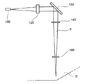
従来技術によるレーザ加工機が図1および図2に示されている。 Laser processing machines according to the prior art are shown in FIGS. 1 and 2.
図1は、空気中にレーザビームの光路を有する、CO2レーザを備えた産業上の加工機を概略的に示している。これは、シングルモードまたはマルチモードのレーザビームBを放射することができるCO2レーザ生成デバイスなどの放射源10と、放射源から放射されたレーザビームを、ビーム伝送光路に沿って、材料WPの近くに配置されてまとめて14で示されている加工ヘッドに向かって導くように構成された複数の反射ミラー12a、12b、および12cと、を含む。加工ヘッド14は、金属材料上に入射する光の伝播軸に沿ってレーザビームを集束させるように構成された、一般的に集束レンズから成るレーザビームの光集束システム16を含む。ノズル18は、集束レンズの下流に配置され、材料の加工面のエリアに向けられたレーザビームによって横切られる。ノズルは、図示しない対応するシステムによって注入されたアシストガスのビームを材料上の加工エリアに向けるように構成されている。アシストガスは、加工プロセスの実行と、得られる加工の品質と、を制御するために使用される。例えば、アシストガスは、金属との発熱反応に有利に働き、切断速度を増加させることができる酸素、または窒素などの不活性ガスを含む。不活性ガスは、材料の溶融には寄与しないが、加工断面のエッジにおける望ましくない酸化から材料を保護し、加工ヘッドを溶融材料の飛散から保護するとともに、材料上に形成された溝の側面を冷却するために使用され、熱的に変化したエリアの膨張を制限することができる。
FIG. 1 schematically shows an industrial processing machine equipped with a CO 2 laser, which has an optical path of a laser beam in the air. This is a source 10 such as a CO 2 laser generation device capable of emitting a single-mode or multi-mode laser beam B, and a laser beam emitted from the source along the beam transmission optical path of the material WP. Includes a plurality of
図2は、光ファイバを通してレーザビームを導く産業上の加工機を概略的に示している。加工機は、シングルモードまたはマルチモードのレーザビームを放射するように構成され、伝送ファイバ、例えばイッテルビウムでドープされたレーザファイバにレーザビームを供給することができるレーザ発生デバイスまたは直接型ダイオードレーザなどの放射源10と、放射源10から放射されたレーザビームを材料Mの近くに配置された加工ヘッド14へ導くように構成された光ファイバケーブル12dと、を含む。発散制御されたファイバから出るレーザビームは、コリメート屈折光学システム20によってコリメートされ、反射光学システム22によって反射された後、放射ノズル18を通過してWP材料上に入射する光の伝播軸に沿って、一般的に集束レンズから成る光集束システム16を通って加工ヘッドで集束される。
FIG. 2 schematically shows an industrial processing machine that guides a laser beam through an optical fiber. The processing machine is configured to emit a single-mode or multi-mode laser beam, such as a laser generator or direct diode laser that can supply the laser beam to a transmission fiber, eg, an itterbium-doped laser fiber. It includes a
図3は、従来技術による例示的な加工ヘッド14を示している。30には、円筒形または円錐形の断面を有する管状の伝送路が示され、その中にBで示すレーザビームが伝送される。放射源10によって生成され、空気中での複数の反射または光ファイバ内の光路によって加工ヘッドに伝送されたレーザビームBは、光伝播軸を加工される材料への入射方向に偏向させる反射偏向要素32上でコリメートされる。光集束システム16は、反射偏向要素32と、下流に配置され、溶融材料の飛散から集束システムを保護するように構成された保護スライド34と、の中間にある。光集束システム16は、ビームの伝播方向(X−Y軸)に対して横方向と、ビームの伝播方向(Z軸)と、にレンズ位置を較正するための機械的調整機構38に結合されたレンズホルダユニット36を含む。
FIG. 3 shows an
加工ヘッドの中でレーザビームが受ける光学的処理が、図4と図5に示されている。 The optical processing that the laser beam receives in the processing head is shown in FIGS. 4 and 5.
放射源Sから生じ、自由空間または光ファイバ内の光伝送路を通ったレーザビームBは、所定の拡がり角で加工ヘッドに到達する。図4中にレンズCによって示されている光コリメーションシステムは、レーザビームをコリメートし、レンズFによって表されている下流に配置された光集束システムに向かわせ、集束したレーザビームを作り出すことができる。第1近似では、光集束システムの下流の理想的なレーザビーム、すなわち平行光線に理想的にコリメートされたレーザビームは、幾何光学の法則によって焦点に集まる。しかし、回折の物理法則は、最良のコリメーションと集束構成であっても、レーザビームが、光集束システムの下流で、ウエストに有限の焦点を有することを示している。このことは、図4中にWで示された領域によって表されており、ここはビームBの焦点エリアに対応する。一般的に、産業上の加工用途では、材料の加工面は、ビームのウエストの横方向の面と一致する。 The laser beam B, which originates from the radioactive source S and passes through an optical transmission line in free space or an optical fiber, reaches the processing head at a predetermined spread angle. The optical collimation system shown by the lens C in FIG. 4 can collimate the laser beam and direct it towards the downstream light focusing system represented by the lens F to produce a focused laser beam. .. In the first approximation, the ideal laser beam downstream of the light focusing system, that is, the laser beam ideally collimated with parallel rays, is focused by the laws of geometrical optics. However, the laws of diffraction physics show that even with the best collimation and focusing configurations, the laser beam has a finite focus on the waist downstream of the light focusing system. This is represented by the region indicated by W in FIG. 4, which corresponds to the focal area of beam B. Generally, in industrial processing applications, the processed surface of the material coincides with the lateral surface of the waist of the beam.
図5は、正常にコリメートされたレーザビームの出力密度の分布を示している。この分布は、シングルモードのビームの場合、典型的にはガウシアン形状であり、回転対称性を有する。すなわち、出力は、ビームの長手軸(Z軸)の周囲に集中し、周囲のスカートに沿って徐々に減少する。または、この分布は、マルチモードビームの場合、回転対称性を有するガウシアン形状の包絡線として説明することができる。 FIG. 5 shows the distribution of the output density of the normally collimated laser beam. This distribution is typically Gaussian-shaped and has rotational symmetry for single-mode beams. That is, the output is concentrated around the longitudinal axis (Z axis) of the beam and gradually decreases along the surrounding skirt. Alternatively, this distribution can be described as a Gaussian-shaped envelope with rotational symmetry in the case of a multimode beam.
シングルモードまたはマルチモードのレーザ放射を備えたビームの使用は、第1近似でガウシアンとして記述され得るものであり、高出力レーザ用途の分野における技術制御要件を満たす。実際、ガウシアンビームは、少しのパラメータによって容易に記述され、放射源から加工機のヘッドまでの光伝送経路に沿った伝播中、容易に制御することができる。なぜなら、ガウシアンビームは、出力分布を変更することなく自身を伝播させる特性を有し、(幾何光学的近似を使用できる場合)遠距離場伝播条件における半径値および発散値によって記述することができるからである。加工経路に沿った近接場における集束ビームの伝播条件であって、幾何光学的近似がもはや有効ではない条件では、いずれの場合もビームは各断面においてガウス出力分布パターンを維持する。 The use of beams with single-mode or multi-mode laser emission can be described as Gaussian in the first approximation and meets technical control requirements in the field of high power laser applications. In fact, the Gaussian beam is easily described with a few parameters and can be easily controlled during propagation along the optical transmission path from the source to the head of the machine. This is because the Gaussian beam has the property of propagating itself without changing the output distribution and can be described by the radius and divergence values under long-field propagation conditions (if geometrical optics approximations can be used). Is. In all cases, the beam maintains a Gaussian output distribution pattern in each cross section under conditions in which the focused beam propagates in the near field along the processing path, where geometrical optics approximation is no longer valid.
これらの理由から、レーザ加工の分野では、レーザビームがガウシアンの(またはほぼガウシアンの)断面の出力分布を有するようにレーザビームの伝播を制御する必要性と、レーザビーム光伝播軸とアシストガス流の重心軸との間の相対的な相互の位置を一度で確立する必要性と、が常に存在していた。 For these reasons, in the field of laser machining, there is a need to control the propagation of the laser beam so that the laser beam has a Gaussian (or nearly Gaussian) cross-sectional output distribution, and the laser beam light propagation axis and assist gas flow. There has always been a need to establish relative reciprocal positions with the axis of the center of gravity of the laser at once.
レーザビームの光伝播軸とアシストガスの流出軸との間の位置決めの(固定性とまではいかなくても)安定性を提供するように構成された従来技術では、複数の解決策が開発されており、これは一般的に2つの軸の一致を含む。レーザビームの光伝播軸とアシストガス流の軸との間の相互位置の調整は、先行技術では、機械(加工ヘッド)の定期的な較正中に、例えば、摩耗によりノズルを交換する必要がある場合に、オペレータによって手動で行われる機械的なセンタリング手順によって実施される。このような機械的なセンタリング手順は、ヘッド上のノズルの位置決めに関連して、レーザビームの光伝播システムの傾斜と中心を調節するための、例えば偏向ミラー上またはコリメーションレンズ上または集束レンズ上のねじ駆動部による、複数の精密な機械的調整を含む。 Multiple solutions have been developed in prior art configured to provide stable (if not fixed) positioning between the light propagation axis of the laser beam and the outflow axis of the assist gas. This generally involves the coincidence of two axes. Adjustment of the mutual position between the light propagation axis of the laser beam and the axis of the assist gas flow, in the prior art, requires the nozzle to be replaced during periodic calibration of the machine (machining head), for example due to wear. In some cases, it is carried out by a mechanical centering procedure performed manually by the operator. Such a mechanical centering procedure involves adjusting the tilt and center of the laser beam light propagation system, eg, on a deflection mirror or on a collimation lens or on a condensing lens, in connection with the positioning of the nozzle on the head. Includes multiple precision mechanical adjustments by screw drive.
この設計上の選択は、純粋なシングルモードビームの場合に、レーザビームの出力のガウス分布によって、およびアシストガスの流出ノズルの口の円形断面によってそれぞれ決定されるビームとアシストガス流の回転対称性を尊重し、加工が続く方向に関して、各加工プロセス(切断、溶接など)の動作の等方性を保証する。 This design choice is the rotational symmetry of the beam and assist gas flow, as determined by the Gaussian distribution of the laser beam output and by the circular cross section of the mouth of the assist gas outflow nozzle, respectively, for a pure single-mode beam. And guarantee the isotropic operation of each processing process (cutting, welding, etc.) with respect to the direction in which processing continues.
CAD/CAMシステムであらかじめ定められた経路と幾何学的形状に従い、電子加工手段によってレーザ加工プロセスを制御する場合、材料上の加工経路に関するプロセスの等方性は、常に有利と考えられてきた。 When controlling a laser machining process by electronic machining means according to a predetermined path and geometry in a CAD / CAM system, the isotropic process of the machining path on the material has always been considered advantageous.
物理的に「不均衡」なシステム、または材料上のレーザビームおよびアシストガスの入射点における回転対称性がないシステムは、加工経路を制御することを複雑かつ困難にし、または質の悪い加工結果につながると広く考えられている。 Physically "unbalanced" systems, or systems without rotational symmetry at the point of incidence of the laser beam and assist gas on the material, make it difficult and difficult to control the machining path, or result in poor machining results. It is widely believed to be connected.
本発明の目的は、動作速度、結果物の質および加工の費用対効果の点で改善された性能を有するレーザ加工方法を提供することにある。 An object of the present invention is to provide a laser machining method having improved performance in terms of operating speed, quality of deliverables and cost effectiveness of machining.
本発明の別の目的は、リアルタイムで制御可能であり、全ての動作条件において正確な加工結果を得ることができ、既存の機械のサイズを増加させることのないレーザ加工方法を提供することにある。 Another object of the present invention is to provide a laser machining method that can be controlled in real time, can obtain accurate machining results under all operating conditions, and does not increase the size of an existing machine. ..
本発明によると、これらの目的は、請求項1に記載の特徴を有する金属材料のレーザ加工方法によって達成される。
According to the present invention, these objects are achieved by a method of laser processing a metal material having the characteristics according to
特定の具体例は、従属請求項の目的であり、その内容は、本明細書の不可欠な部分として理解されるべきである。 A particular embodiment is the object of the dependent claims, the content of which should be understood as an integral part of the specification.
本発明の更なる目的は、特許請求の範囲に記載の金属材料のレーザ加工用の機械およびコンピュータプログラムである。 A further object of the present invention is a mechanical and computer program for laser machining of metallic materials as described in the claims.
要約すると、本発明は、レーザビームとアシストガス流アセンブリの回転対称性の破れ、すなわち、レーザ放射の伝播軸とアシストガス流の流出軸との間の一致条件からのずれにより、同一の性能を有する加工プロセスよりも、速度、品質、および費用対効果の点でより良い利益を得ることができるという考察に基づくものである。 In summary, the present invention provides the same performance due to rotational symmetry breaking of the laser beam and assist gas flow assembly, i.e., deviation from the coincidence condition between the propagation axis of the laser emission and the outflow axis of the assist gas flow. It is based on the idea that you can get better benefits in terms of speed, quality, and cost effectiveness than the processing process you have.
回転対称性の破れの適用および利用のモードは、異なる場合がある。特に、このようなモードは、アシストガス流の対称軸に対する加工レーザビームの光軸の位置の「静的」変更と、アシストガス流の対称軸に対する加工レーザビームの光軸の位置の「動的」変更または「見かけ上のビーム」(apparent beam)方式と、を含む。 Modes of application and utilization of rotational symmetry breaking may differ. In particular, such modes include a "static" change in the position of the optical axis of the processed laser beam with respect to the axis of symmetry of the assist gas flow and a "dynamic" position of the optical axis of the processed laser beam with respect to the axis of symmetry of the assist gas flow. Includes "modification or" apparent beam "methods, and.
「静的」変更の場合、アシストガス流の対称軸に対するレーザビームの光軸の相対的な位置(基準方向とみなされる、加工経路に沿った局所的な進行方向に対する距離、角度)は、固定されるか、または加工プロセスの進行速度に相当する相対速度(すなわち、同じオーダーの大きさの速度)で変化する。 In the case of "static" change, the relative position of the optical axis of the laser beam with respect to the axis of symmetry of the assist gas flow (distance, angle with respect to the local traveling direction along the processing path, which is regarded as the reference direction) is fixed. Or change at a relative speed (ie, a speed of the same order of magnitude) that corresponds to the speed of progress of the machining process.
アシストガス流の並進方向に、アシストガス流の対称軸よりも前に(すなわち、切断加工の場合に加工される材料の表面上のガス流の対称軸の入射エリアよりも前に)、レーザビームの光軸の位置があるという不均衡の結果、加工速度の点でより良い性能が得られる。このような不均衡は、実際に、アシストガス流によって打たれる溶融した溝エリアを生成する。溶融した溝エリアは、軸が対称的に一致する場合よりも大きい。言い換えれば、ガス流より前の材料へのレーザビームの入射により、軸が対称的に一致する場合と比較して、同じ速度においてより低い圧力でガス供給をすることができ、より低い圧力に比例して低いガス消費を保証することができる。 The laser beam in the translational direction of the assist gas flow, before the axis of symmetry of the assist gas flow (ie, before the incident area of the axis of symmetry of the gas flow on the surface of the material being machined in the case of cutting). As a result of the imbalance of the position of the optical axis of, better performance is obtained in terms of machining speed. Such an imbalance actually creates a molten groove area struck by the assist gas stream. The molten groove area is larger than when the axes are symmetrically aligned. In other words, the injection of the laser beam into the material prior to the gas stream allows the gas to be supplied at a lower pressure at the same velocity and proportional to the lower pressure compared to the case where the axes are symmetrically aligned. And low gas consumption can be guaranteed.
「動的」変更または「見かけ上のビーム」方式の場合、アシストガス流の対称軸に対するレーザビームの光軸の相対的な位置(基準方向とみなされる、加工経路に沿った局所的な進行方向に対する距離、角度)は、加工プロセスの進行速度よりも少なくとも1桁大きい相対速度で変化する。レーザビームの光軸は、アシストガス流の軸に対する所定の周囲運動周波数での定期的な運動で制御され、それにより、材料に対する加工プロセスは、周囲運動周波数よりも1桁小さい周波数スケールでのビームの運動の包絡線によって記述可能な見かけ上のビームに見えるようになる。 In the case of the "dynamic" modification or "apparent beam" method, the position of the optical axis of the laser beam relative to the axis of symmetry of the assist gas flow (the local direction of travel along the machining path, which is considered the reference direction). The distance, angle) varies at a relative speed that is at least an order of magnitude higher than the progress speed of the machining process. The optical axis of the laser beam is controlled by regular motion at a predetermined ambient motion frequency with respect to the axis of the assist gas flow, so that the machining process for the material is a beam on a frequency scale that is an order of magnitude lower than the ambient motion frequency. It becomes visible as an apparent beam that can be described by the envelope of the motion of.
アシストガス流の軸の伝播方向に対する光軸の、往復運動すなわち振動の結果、例えば幾分細長い楕円形の見かけ上のビームが決定され、溶融した溝のより大きな照射、すなわち、溝の中でより長く持続する照射を可能にし、その結果、伝播方向内の材料による放射の吸収がより多くなる。この技術により電力を節約することができる。なぜなら、この技術は、レーザビームの出力1ワット当たりの生産量を増加させ、ガスを節約するからである。なぜなら、この技術は、従来技術より粘性の低い材料を維持し、これにより溶融材料をより少ないガス圧で溝から押し出すことができるからである。 As a result of the reciprocating or vibration of the optical axis with respect to the direction of propagation of the axis of the assist gas flow, for example a somewhat elongated elliptical apparent beam is determined, a larger irradiation of the molten groove, i.e. more in the groove. It allows for long lasting irradiation, resulting in more absorption of radiation by the material in the direction of propagation. This technology can save power. This is because this technology increases the production of the laser beam per watt output and saves gas. This is because the technique maintains a less viscous material than the prior art, which allows the molten material to be pushed out of the groove with less gas pressure.
別の方法では、光軸、すなわち、レーザ出力分布の重心のアシストガス流の軸周りの円振動運動の結果として、円形の見かけ上のビームが決定される。これにより、レーザビームの出力分布の直径(見かけ)を増加させることができ、したがって、同一の圧力で溝内のより大きなガス流を得ることができる。 Alternatively, a circular apparent beam is determined as a result of the circular vibrational motion around the optical axis, i.e., the axis of the assist gas flow of the center of gravity of the laser output distribution. This allows the diameter (apparent) of the output distribution of the laser beam to be increased, thus resulting in a larger gas flow in the groove at the same pressure.
本発明によると、従来技術のシステムへの前述の考察の適用は、レーザビームの形状をリアルタイムで制御することによって、すなわち、ビームの横モード出力分布の変更によって、アシストガス流の対称軸に対する加工レーザビームの光軸の位置の効果的な制御を実施することによって達成され、ビームの形状と実効直径を実質的に保持する。 According to the present invention, the application of the above considerations to prior art systems is by controlling the shape of the laser beam in real time, i.e. by changing the transverse mode output distribution of the beam, to process the assist gas flow with respect to the axis of symmetry. Achieved by performing effective control of the position of the optical axis of the laser beam, it substantially retains the shape and effective diameter of the beam.
本発明は、制御された変形を伴う光学システムを使用する原理に基づくものである。この原理は、産業上の用途の高出力レーザビームを成形するための光信号の(したがって低出力光放射の)処理のための科学的利用においてそれ自体知られている。 The present invention is based on the principle of using an optical system with controlled deformation. This principle is known in its own right for scientific use in the processing of optical signals (and thus low power light emission) to form high power laser beams for industrial applications.
レーザビーム光学伝送システムの中の制御された変形光学システムの適用は、急速に変更可能な方法で得られるレーザビームの成形の範囲を拡大させることと、レーザ放射の伝播軸とアシストガスの流出軸との間の相互位置を極度の精度で調整することと、その結果、機械加工プロセスの性能を改善し、または革新的な機械加工プロセスを実施することと、を可能にする。 The application of controlled deformation optics within a laser beam optical transmission system expands the range of laser beam shaping obtained in a rapidly changeable manner and the propagation axis of laser radiation and the outflow axis of assist gas. It is possible to adjust the mutual position between and with extreme precision and, as a result, improve the performance of the machining process or carry out an innovative machining process.
有利には、本発明の方法は、アシストガス流出領域の中心に高精度でレーザビームを向けることを可能にし、したがって、所定の加工のために機械を設定する場合にオペレータの介入によって精密な機械調節をする必要があることを防止する。 Advantageously, the method of the present invention makes it possible to direct the laser beam to the center of the assist gas outflow region with high precision, and therefore a precision machine with operator intervention when setting the machine for a given machining. Prevents the need for adjustment.
更に有利には、本発明の方法は、レーザビームの光軸の位置を、アシストガス流の軸(これは必ずしも同軸上に整列された位置ではない)に対して所定の空間的関係に従って迅速な調整時間で制御することを可能にする。このような位置制御は、加工サイクルの「前設定」として実行されるだけでなく、材料上の加工経路に沿ったレーザビームの光軸とアシストガス流の軸との間の所望の相互位置を制御するように加工プロセス中にリアルタイムで実施されてもよい。 More advantageously, the method of the present invention rapidly positions the optical axis of the laser beam according to a predetermined spatial relationship with respect to the axis of the assist gas flow, which is not necessarily a coaxially aligned position. Allows control by adjustment time. Such position control is not only performed as a "pre-setting" of the machining cycle, but also at the desired mutual position between the optical axis of the laser beam and the axis of the assist gas flow along the machining path on the material. It may be carried out in real time during the machining process to control.
言い換えると、本発明の方法は、加工プロセス中、例えば、アシストガス流の軸から所定の距離にあり、かつ加工経路の現在の方向(加工の進行方向)に対して所定の角度方向にあるレーザビームの光軸の位置を瞬間的に制御することによって、レーザビームの光軸とアシストガス流の軸との間の所定の相互配置ストラテジを自動的に設定して、維持することを可能にする。 In other words, the method of the present invention is a laser during the machining process, for example, at a predetermined distance from the axis of the assist gas flow and at a predetermined angular direction with respect to the current direction of the machining path (machining direction). By momentarily controlling the position of the optical axis of the beam, it is possible to automatically set and maintain a predetermined interposition strategy between the optical axis of the laser beam and the axis of the assist gas flow. ..
本発明の方法は、更に、加工プロセス中に、例えば、所定の加工経路に沿った材料上の加工エリアの空間位置の関数としての、または加工経路に沿った進行速度の変化、加工材料の厚さの変化、加工される材料の表面に対するアシストガスの入射角の変化などの他のパラメータの関数としての、レーザビームの光軸とアシストガス流の軸との間の所定の相互配置可変ストラテジを自動的に設定することを可能にする。 The methods of the present invention further provide during the machining process, for example, as a function of the spatial position of the machining area on the material along a predetermined machining path, or a change in the rate of travel along the machining path, the thickness of the machining material. A predetermined interposition variable strategy between the optical axis of the laser beam and the axis of the assist gas flow as a function of other parameters such as changes in velocity, changes in the angle of incidence of the assist gas on the surface of the material being machined. Allows you to set it automatically.
切断加工と溶接加工の両方において、加工経路に沿った進行速度の変化は、加工ヘッドの様々な機械制御軸の必要的な停止から生じる。停止は、経路自体の定義に寄与する。例えば、停止は、加工方向またはヘッドの向きの逆転に起因する。ヘッドは、停止するまで減速され、その後、加速される。 In both cutting and welding, the change in velocity along the machining path results from the necessary stops of the various machine control axes of the machining head. Stopping contributes to the definition of the route itself. For example, the stop is due to a reversal of machining direction or head orientation. The head is decelerated until it stops and then accelerated.
知られかつ期待される加工材料の厚さの変化は、厚さによって異なる材料自体の中の対応する進行速度および焦点スポット位置を必要とするだけでなく、回転対称性を破るために異なるモード、すなわち、前記厚さの関数としてのアシストガス流の対称軸に対する加工レーザビームの光軸の位置の「静的」または「動的」な変更をも必要とする。 Known and expected changes in the thickness of the processed material not only require the corresponding travel speed and focal spot position within the material itself, which varies depending on the thickness, but also in different modes to break the rotational symmetry, That is, it also requires a "static" or "dynamic" change in the position of the optical axis of the processed laser beam with respect to the axis of symmetry of the assist gas flow as a function of the thickness.
最後に、加工材料の表面に対するアシストガスの入射角の変化は、ガス流の軸の周りに異なるレーザ出力分布を必要とし、これにより切断性能を改善し、より広い溝に起因して、またはアシストガスのより良好な供給に起因して、より安定した加工を保証する。 Finally, changes in the angle of incidence of the assist gas with respect to the surface of the work material require different laser power distributions around the axis of the gas flow, which improves cutting performance and is due to or assisted by wider grooves. Guarantees more stable machining due to a better supply of gas.
レーザ放射の伝播軸とアシストガス流の軸との間の相互位置の制御は、アシストガス流の供給エリアを定義するアシストガス流の軸の所定の近傍内で、金属材料上の加工面のエリア内のビームの横モード出力分布を制御する手段によって、本発明によって実施される。アシストガス流の供給エリア(本発明の制御方法の動作のボリュームフィールド(volumetric field)を表すもの)は、加工ヘッドのノズルの「影響を受けたボリューム」(affected volume)として識別可能である。典型的には、ノズルは、直径が1mm〜3.5mmである口を有し、円錐台に典型的な寸法である6mm〜20mmの高さと、口の直径より1〜3mm大きい直径の(ノズルのある)小底面と、特徴的な寸法が円錐台のボリュームの高さおよび母線の傾斜角(典型的には15°〜30°)の関数である大底面と、を有する。適切には、ノズルのボリュームはできる限り小さく、かつ加工される表面の凹部内でも動作することができるようにできる限り薄い外観を有する。 The control of the mutual position between the propagation axis of the laser radiation and the axis of the assist gas flow is the area of the machined surface on the metal material within a predetermined neighborhood of the axis of the assist gas flow that defines the supply area of the assist gas flow. It is carried out by the present invention by means of controlling the transverse mode output distribution of the beam within. The supply area of the assist gas flow (representing the volumetric field of operation of the control method of the present invention) can be identified as the "affected volume" of the nozzle of the machining head. Typically, the nozzle has a mouth with a diameter of 1 mm to 3.5 mm, a height of 6 mm to 20 mm, which is a typical dimension for a truncated cone, and a diameter 1-3 mm larger than the diameter of the mouth (nozzle). It has a small bottom (with) and a large bottom whose characteristic dimensions are a function of the height of the volume of the truncated cone and the angle of inclination of the generatrix (typically 15 ° to 30 °). Suitably, the volume of the nozzle is as small as possible and has the thinnest possible appearance so that it can operate even within the recesses of the surface to be machined.
有利には、本発明の方法によって実行される自動制御は、100Hz〜10kHzの動作周波数で、リアルタイムで実行されてもよい。 Advantageously, the automatic control performed by the method of the present invention may be performed in real time at an operating frequency of 100 Hz to 10 kHz.
本発明の方法を実行するように構成された制御システムは、加工ヘッドに一体化することができるので、従来技術のシステムとは有利に区別される。すなわち、制御システムは、レーザビームの生成と、およびレーザビームの加工ヘッドへの伝送と、から独立している。 A control system configured to perform the methods of the invention can be integrated into the machining head and is therefore advantageously distinguished from prior art systems. That is, the control system is independent of the generation of the laser beam and the transmission of the laser beam to the machining head.
さらに、本発明の方法は、特定の加工用の機械を設定しまたは作動させるための既知の解決策とは異なる。既知の解決策では、アシストガス流に対する光ビームの位置は、従来のウォブリング技術の場合と同様に、オペレータによる手動介入の結果として調整可能である。または、光ビームの入射方向の変更は、所定の論理に従って実施される。これにより、加工プログラムを設定するときにプログラムされた高度に動的な振動が、加工全体を通してレーザビームの光伝播軸に繰り返し与えられる。これに対して本発明の方法は、レーザビームの光伝搬軸の位置を、加工経路に沿ったビームの位置の関数として、リアルタイムで効果的に制御することを可能にする。それにより、加工経路に沿った所定の位置に生じるプログラムされた加工条件に応じて、光ビームの光伝播軸とアシストガス流の軸との相互位置を適時に変更することができる。このようなプログラムされた加工条件は、説明のための非限定的な例として、所定の加工経路に沿った現在の加工位置(または、より一般的には、現在の加工面のエリア)および/または材料上の加工経路の現在の方向および/またはアシストガス流の軸の並進方向を含む。 Moreover, the methods of the present invention differ from known solutions for setting up or operating a particular machining machine. In a known solution, the position of the light beam relative to the assist gas stream can be adjusted as a result of manual intervention by the operator, as in conventional wobbling techniques. Alternatively, the change of the incident direction of the light beam is carried out according to a predetermined logic. This causes the highly dynamic vibrations programmed when setting the machining program to be repeatedly applied to the light propagation axis of the laser beam throughout the machining. On the other hand, the method of the present invention makes it possible to effectively control the position of the light propagation axis of the laser beam in real time as a function of the position of the beam along the processing path. Thereby, the mutual position between the light propagation axis of the light beam and the axis of the assist gas flow can be changed in a timely manner according to the programmed processing conditions generated at a predetermined position along the processing path. Such programmed machining conditions, as a non-limiting example for illustration, include the current machining position (or, more generally, the area of the current machining surface) along a predetermined machining path and /. Or includes the current direction of the machining path on the material and / or the translational direction of the axis of the assist gas flow.
本発明の更なる特徴および利点は、添付の図面を参照して、非限定的な例として与えられた一具体例の以下の詳細な説明の中で、より詳細に説明される。 Further features and advantages of the present invention will be described in more detail in the following detailed description of one embodiment given as a non-limiting example with reference to the accompanying drawings.
図1〜5は、従来技術に関連して既に説明した。その内容は、本発明の教示による加工プロセスを実行するために制御される加工機の製造に共通であるとしてここで参照される。 FIGS. 1 to 5 have already been described in relation to the prior art. Its contents are referred to herein as being common to the manufacture of machines controlled to perform the machining process according to the teachings of the present invention.
本発明による金属材料のレーザ加工のための機械の加工ヘッド内のレーザビームの光路が図6に示されている。 The optical path of the laser beam in the machining head of the machine for laser machining of metal materials according to the present invention is shown in FIG.
図6の光学システムは、レーザビームBの入力デバイス100を含む。これは例えば光ファイバケーブルの端部または自由空間内の光路に沿って放射源によって伝播されるビームの光ピックアップシステムなどである。そこから所定の拡がり角でレーザビームBが出る。
The optical system of FIG. 6 includes an
入力デバイス100の下流には、光コリメーションシステム120、例えばコリメーションレンズ(典型的には、レーザ切断機の加工ヘッド用のコリメーションレンズは、50mm〜150mmの焦点距離を有する)が配置される。その下流で、コリメートされたレーザビームは、スクリーンまたは保護ガラス160を通して加工面Π上にビームを集束するように構成された光集束システム140、例えば集束レンズ(典型的には、レーザ切断機の加工ヘッド用の集束レンズは、100mm〜250mmの焦点距離を有する)に導かれる。
Downstream of the
コリメーション光学システム120と光集束システム140との間の光路には、光学的ビーム成形手段180がある。
In the optical path between the collimation
特に、図6に示されているレーザビームの光路の概略図を参照すると、本発明は、レーザビームを成形するための光学的手段180と、材料の所定の加工平面上において、制御された方法でレーザビームの横モード出力分布を達成するための前記手段の制御と、を構成することに関する。図では、例示的な具体例の中でレーザビームを成形するための光学的手段180が示されている。光学的手段180は、ビームの伝播方向に対して45°の対称軸を有するように配置されている。
In particular, with reference to the schematic view of the optical path of the laser beam shown in FIG. 6, the present invention relates to an
この目的のために、レーザビームを成形する光学的手段180は、制御された表面を有する変形可能な反射素子200として作られており、制御表面は、図7に示されているように、静止状態では、基準反射面上にある反射面を形成する、独立して移動可能な複数の反射エリアを含む。上記の変形可能な制御表面反射素子200は、連続的なホイルミラーを提供する。その反射面は、静止状態で採用された基準平坦反射面に対して3次元的に変更可能である。上記の変形可能な制御表面反射素子200は、連続的な曲率を備えた反射面を有し、この反射面は、図中に200a、200b、...で示された対応する複数の移動モジュールが後方に関連付けられた複数の反射エリアを含む。また、この反射面は、レーザ光の波長の高反射コーティング(少なくとも99%)を併用し、直接チャネリングにより水で冷却されたコンタクトホルダにマウントすることによって、高い光出力での使用のために適切に処理される。移動モジュールは、連続曲率反射面に不可欠であり、独立して移動可能である。連続的な曲率を有する反射表面の反射エリアは、その間にエッジを有さない。すなわち、全反射面は、全方向に連続的な局所微分を有する。上記の複数の移動モジュール200a、200bの移動は、対応する反射エリアの、静止状態で採用された基準平坦反射面に対する前後移動などの並進移動を含み、または対応する反射エリアの、静止状態で採用された基準平坦反射面に対して平行な軸の周りの回転移動を含み、またはそれらの組合せを含む。反射面の変形、すなわち移動モジュール200a、200bの移動は、好適には、既知の圧電技術によって行われる。圧電技術により、移動モジュールの移動と、その結果としての反射エリアの位置、すなわち、他から独立に、所定の自由度での各モジュールの並進および/または回転による動きの組合せの結果として生じる反射エリアの位置の変更とを、典型的にはおよそ±40μmの移動距離で、制御することができる。これにより、ゼルニケ多項式の組合せによって定義される連続曲率面の近似を得ることができ、これにより、所望の処理用途の目的に応じて、レーザビームの光伝播軸の位置調整、またはより一般的には、レーザビームの横モード出力分布の制御を、(少なくとも理論的におよび実際には所望の目的のために十分に近似して)行うことができる。
To this end, the optical means 180 for forming the laser beam is made as a deformable
図7は、図6のダイアグラムに示すように、45°のコリメートされたレーザビームの入射角に対して採用される、楕円形の輪郭を有する反射素子200および関連する後部移動モジュールの好適な具体例を示している。このような具体例は、単に概略的なものに過ぎず、本発明の実施を限定するものではないことが理解されるべきである。コリメートされたレーザビームの入射が静止状態で素子200の表面に対して垂直またはほぼ垂直である別の好適な具体例では、反射素子200の輪郭は、円形の輪郭である。
FIG. 7 is a preferred embodiment of the elliptical contoured
楕円形の輪郭を有する反射素子の具体例では、反射素子は、38mmの長軸と27mmの短軸を有する。この輪郭は、コリメーション光学システム120によって得られるミラーに対して入射するレーザビームの最大の横方向開口サイズに対応する、
In a specific example of a reflective element having an elliptical contour, the reflective element has a major axis of 38 mm and a minor axis of 27 mm. This contour corresponds to the maximum lateral aperture size of the laser beam incident on the mirror obtained by the collimation
特に、好適な具体例では、上記の変形可能な制御表面反射素子200は、対応する複数の移動モジュールによって独立に移動可能な複数の反射エリアを含む。この移動モジュールは、中心エリアと、中心エリアと同心の複数のランクの円形冠状扇形(circular crown sectors)と、を含むものである。この好適な具体例では、同心の円形冠状扇形のランクの総数は6個であり、各ランクに対して円形冠状扇形の数は8個であり、円形冠状扇形の高さは、反射素子の外側に向かって、径方向に第1ランクから第3ランクまで増加し、かつ第4ランクから第6ランクまで増加する。第4ランクの円形冠状扇形の高さは、第1ランクの円形冠状扇形の高さと第2ランクの円形冠状扇形の高さとの中間である。好適には、設計された反射素子200の制御構造を簡単にするために、周囲の円形冠を形成する複数の円形区域は固定され、内側の円形冠状扇形のランクのみが移動可能であることにより、総数が41個に限定されたアクチュエータを使用してもよい。
In particular, in a preferred embodiment, the deformable control
一般的に、円形区域のランクの数、円形冠状扇形の数、および円形冠状扇形の高さは、レーザビームの所定の所望の横モード出力分布を得るために必要な反射面の形状によって、選択された数の反射エリアの反射素子上に入射するレーザビームの横モード出力分布の傾向のシミュレーション手順を用いて、決定される。実際、素子200の反射面の制御された変形可能性は、レーザビームの位相に作用することによって、焦点面上のレーザビームの強度の制御された変化を誘導する。この好適な具体例では、反射素子200の表面の変形は、ゼルニケ多項式の組合せに起因する反射面を決定するように制御される。したがって、反射素子200の反射エリアの移動によって制御される位相変動に応じた焦点面上のレーザビームの強度の分布は、有利には、数学的計算方法を用いてシミュレートされる。
In general, the number of ranks in a circular area, the number of circular sectors, and the height of the circular sectors are selected according to the shape of the reflective surface required to obtain the desired transverse mode output distribution of the laser beam. It is determined using the procedure of simulating the tendency of the transverse mode output distribution of the laser beam incident on the reflecting elements of the specified number of reflecting areas. In fact, the controlled deformability of the reflective surface of the
図7に示されている反射素子200の表面の下位区分の幾何学的形状は、反射エリアの移動モジュールの幾何学的形状に対応し、ビーム成形において大きな自由度を有し、回転対称性の保持とは関係なく、様々な形態の横モード出力分布を得るためのシミュレーション手順によって発明者らによって決定された。他の、出力分布の形状の変化は必要でないが、光伝搬軸に対する変位のみが変化する必要があるガウス分布に厳密に関連する用途の場合、より単純な形状、例えば等間隔のランク、すなわち、円形冠状扇形の高さが全ての区域のランク間で一定であるランクを使用することができる。ビーム出力分布の回転対称性が保持される用途では、径方向に独立した円形冠状の複数の反射エリアおよび各移動モジュールを設けることができる。
The geometric shape of the subdivision of the surface of the
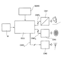
図8は、本発明の方法の実施のための金属材料のレーザ加工のための機械の電子制御システムの回路図を示している。 FIG. 8 shows a circuit diagram of an electronic control system of a machine for laser machining of metallic materials for the practice of the method of the present invention.
システムは、図中にECUでまとめて示されている電子処理および制御手段を含む。これらの手段は、機械に搭載された1つの処理ユニットの中に統合され、または分散型で実装され、したがって、例えば加工ヘッドを含む機械の異なる部分に配置された処理モジュールを含んでもよい。 The system includes electronic processing and control means collectively shown by the ECU in the figure. These means may include processing modules integrated or distributed in one processing unit mounted on the machine and thus located in different parts of the machine, including, for example, machining heads.
電子処理および制御手段ECUに関連するメモリ手段Mは、例えば加工ヘッドおよび/または加工される材料に対する移動命令の形で所定の加工経路を含む所定の加工パターンまたはプログラムと、光ビームの出力分布、ビームの出力強度、およびレーザビーム活性化時間を意味する加工経路の関数としての物理加工パラメータと、を記憶する。 Electronic processing and control means The memory means M associated with the ECU includes a predetermined machining pattern or program including a predetermined machining path in the form of a movement command for a machining head and / or a material to be machined, and an output distribution of an optical beam. The output intensity of the beam and the physical machining parameters as a function of the machining path, which means the laser beam activation time, are stored.
電子処理および制御手段ECUは、メモリ手段Mにアクセスして加工経路を獲得し、かつその経路に沿って加工レーザビームの適用を制御するように構成される。所定の加工経路に沿ったレーザビームの適用の制御は、アシストガス流の供給を制御することと、所定の加工パターンまたはプログラムを参照することによって、すなわち、メモリ手段から獲得した加工経路情報と加工パラメータとによって、所定の加工エリアに向かってレーザビームの所定の出力分布の放射を制御することと、を含む。 The electronic processing and control means ECU is configured to access the memory means M to acquire a machining path and control the application of the machining laser beam along the path. The control of the application of the laser beam along the predetermined machining path is by controlling the supply of the assist gas flow and by referring to the predetermined machining pattern or program, that is, the machining path information and machining obtained from the memory means. The parameters include controlling the emission of a given output distribution of the laser beam towards a given machining area.
センサ手段SENSは、加工ヘッドと加工される材料との間の相互位置と、そのような位置の経時変化と、をリアルタイムで検出するために、機械上に配置される。 The sensor means SENS is arranged on the machine to detect the mutual position between the processing head and the material to be processed and the change of such position with time in real time.
電子処理および制御手段ECUは、センサヘッドから、加工ヘッドと加工される材料との間の経時的な相互位置、すなわち、現在の加工面のエリアおよび/または現在の加工経路の方向の経時変化を示すSENS信号を受信するように構成されている。 The electronic processing and control means ECU determines the mutual position of the processing head and the material to be processed with time from the sensor head, that is, the change with time in the area of the current processing surface and / or the direction of the current processing path. It is configured to receive the indicated SENS signal.
電子処理および制御手段ECUは、加工の機械パラメータを制御する第1制御モジュールCM1を含む。第1制御モジュールCM1は、第1コマンド信号CMD1をアクチュエータ手段の既知のアセンブリに発するように構成されている。このアクチュエータ手段は、機械の特定の具体例によって許容された自由度に沿って加工ヘッドを移動させるアクチュエータ手段と、加工される材料を加工ヘッドの位置に対して移動させるアクチュエータ手段とを含む。第1制御モジュールCM1は、アクチュエータ手段と協働して加工ヘッドを移動させて、加工ヘッドのノズルで加工されている材料上にプログラムされた加工経路を提供するように構成されている。これらのアクチュエータ手段は、当該技術分野において公知であるため、詳細には説明しない。 The electronic processing and control means ECU includes a first control module CM1 that controls machine parameters for processing. The first control module CM1 is configured to emit a first command signal CMD 1 to a known assembly of actuator means. The actuator means includes an actuator means for moving the machining head along a degree of freedom allowed by a particular embodiment of the machine and an actuator means for moving the material to be machined with respect to the position of the machining head. The first control module CM1 is configured to move the machining head in cooperation with the actuator means to provide a programmed machining path on the material being machined by the nozzle of the machining head. These actuator means are known in the art and will not be described in detail.
電子処理および制御手段ECUは、加工の物理パラメータを制御する第2制御モジュールCM2を含む。第2制御モジュールCM2は、アシストガス流供給手段と、レーザビームを生成して送信する制御手段と、に対して第2コマンド信号CMD2を発するように構成されている。 The electronic processing and control means ECU includes a second control module CM2 that controls physical parameters of processing. The second control module CM2 is configured to emit a second command signal CMD 2 to the assist gas flow supply means and the control means for generating and transmitting the laser beam.
電子処理および制御手段ECUは、光加工パラメータを制御する第3制御モジュールCM3を含む。第3制御モジュールCM3は、制御表面反射素子の独立して移動可能な反射エリアの移動モジュールを実現するための、すなわち、移動モジュールの相互の空間的な移動(反射素子の光軸に沿った並進またはそれに対する傾斜)を制御するための、光学的ビーム成形手段の変形可能な制御表面反射素子200に対して、第3コマンド信号CMD3を発するように構成されている。コマンド信号CMD3は、1つ以上のコードモジュールを含むコンピュータプログラムによって処理される。このコードモジュールは、得られるべき所定のレーザビームの成形に従って本発明の方法を実施するための、調整モデルまたはプログラムの命令を有する。すなわち、このコードモジュールは、レーザビームの所定の横モード出力分布と、続いて、金属材料の少なくとも1つの加工面のエリア内の材料に対して入射する光伝播軸に沿った瞬間加工条件の関数としての、レーザビームの光伝播軸の所定の位置と、を達成するための、調整モデルまたはプログラムの命令を有する。材料の加工面は、例えば、厚い材料、すなわち、典型的には集束ビームのレイリー長の1.5倍を越える厚さ(典型的な事例では、4mmより大きく30mmまでの厚さ)を有する材料の切断または穿孔のための、材料の表面平面、または材料の厚さが深さ方向に変化する平面である。前述のコマンド信号CMD3は、コンピュータプログラムによって処理されて、瞬間加工条件、すなわち、金属材料上の現在の加工面および/または現在の加工経路の方向に従って、アシストガス流の軸の所定の近傍内かつアシストガスの供給エリア内で、レーザビームの所定の横モード出力分布を達成する。
The electronic processing and control means ECU includes a third control module CM3 that controls optical processing parameters. The third control module CM3 is for realizing the movement module of the independently movable reflection area of the control surface reflection element, that is, the mutual spatial movement of the movement modules (translation along the optical axis of the reflection element). It is configured to emit a third command signal CMD 3 to the deformable control
したがって、電子処理および制御手段ECUは、アシストガス流の軸の現在位置および/または現在の並進方向を検出し、金属材料上の所定の加工経路に沿ったアシストガス流の軸の相対的な並進を制御して、アシストガス流の軸の並進の現在位置および/または検出された現在の方向に従って、レーザビームの光伝播軸の位置またはレーザビームの横モード出力分布を自動的に調整するように構成される。 Therefore, the electronic processing and control means ECU detects the current position and / or the current translation direction of the axis of the assist gas flow, and the relative translation of the axis of the assist gas flow along a predetermined processing path on the metal material. To automatically adjust the position of the laser beam's light propagation axis or the laser beam's transverse mode output distribution according to the current translational position of the assist gas flow axis and / or the detected current direction. It is composed.
レーザビームの光伝播軸の位置は、反射エリアの移動モジュールを制御することによって調節されて、それぞれの静止状態に対して、全体として反射素子の所定の全体的な傾斜移動を実行し、加工される材料上のレーザビームスポットの空間的な並進を決定する。 The position of the light propagation axis of the laser beam is adjusted by controlling the movement module of the reflection area to perform and process a predetermined overall tilt movement of the reflecting element as a whole for each stationary state. Determines the spatial translation of the laser beam spot on the material.
1つの具体例によると、レーザビームの光伝播軸の位置は、金属材料の切断加工中、加工経路に沿ったアシストガス流の軸の現在位置に対して前方のエリアおよび後方のエリアに選択的または交互に調整される。これは、好適には、例えば、切断加工の実行速度と切断される材料の厚さとの関数として、切断経路を求める際に行われる。 According to one embodiment, the position of the light propagation axis of the laser beam is selective in the front area and the rear area with respect to the current position of the axis of the assist gas flow along the processing path during the cutting process of the metal material. Or it is adjusted alternately. This is preferably done, for example, when determining the cutting path as a function of the execution speed of the cutting process and the thickness of the material to be cut.
「静的」変更の場合、アシストガス流の並進方向に、アシストガス流の対称軸よりも前に(すなわち、切断加工の場合に加工される材料の表面上のガス流の対称軸の入射エリアよりも前に)、レーザビームの光軸の位置があるという不均衡の結果、加工速度の点でより良い性能が得られる。このような不均衡は、アシストガス流によって打たれる溶融した溝エリアを生成する。溶融した溝エリアは、軸が対称的に一致する場合よりも大きい、言い換えれば、ガス流の前方の材料へのレーザビームの入射により、軸が対称的に一致する場合と比較して、同じ速度においてより低い圧力でガス供給をすることができ、より低い圧力に比例して低いガス消費を保証することができる。 For "static" changes, in the translational direction of the assist gas flow, before the axis of symmetry of the assist gas flow (ie, the incident area of the axis of symmetry of the gas flow on the surface of the material being machined in the case of cutting). Better performance in terms of machining speed is obtained as a result of the imbalance of the position of the optical axis of the laser beam (before). Such an imbalance creates a molten groove area struck by the assist gas stream. The molten groove area is larger than when the axes are symmetrically aligned, in other words, the same velocity as when the axes are symmetrically aligned due to the incident of the laser beam on the material in front of the gas stream. The gas can be supplied at a lower pressure in, and a lower gas consumption can be guaranteed in proportion to the lower pressure.
「動的」変更または「見かけ上のビーム」方式の場合、アシストガス流の軸の伝播方向に対して往復する光軸の振動運動の結果、例えば細長い準楕円形状を有する見かけ上のビームが決定され、溶融した溝のより良好な照射、すなわち、溝の上でより長く持続する照射が可能となり、その結果、伝播方向内の材料による放射の吸収がより多くなる。この技術により電力を節約することができる。なぜなら、この技術は、レーザビームの出力1ワット当たりの生産量と、ガス節約とを増加させるからである。なぜなら、この技術は、従来技術に比べて粘性の低い材料を維持し、これにより溶融材料をより少ないガス圧で溝から押し出すことができるからである。 In the case of the "dynamic" modification or "apparent beam" method, the vibrational motion of the optical axis reciprocating with respect to the propagation direction of the axis of the assist gas flow results in, for example, an apparent beam having an elongated quasi-elliptic shape. It allows for better irradiation of the molten groove, i.e., longer lasting irradiation on the groove, resulting in more absorption of radiation by the material in the direction of propagation. This technology can save power. This is because the technology increases the production of the laser beam per watt output and the gas savings. This is because the technique maintains a less viscous material than the prior art, which allows the molten material to be pushed out of the groove with less gas pressure.
別の具体例では、レーザビームの光伝搬軸の位置は、金属材料の穿孔加工中のアシストガス流の軸の現在位置の周りの円形の経路に沿うように調整される。これにより、直径がより小さいガウスビームで開始しても、2つの利点を有し、大きい直径の円対称性を有する「見かけ上のビーム」を生成することができる。第1の利点は、加工の終了時に穿孔直径が増加することである。これは、切断動作の開始時のデリケートな段階において、レーザビームと加工される材料の厚さ内の前進する前部との間の良好な結合を可能にするとともに、開始時に溶融材料をより効率的に排出することができるより大きなガス流を可能にする。第2の利点は、穿孔加工中、円運動が、必ず材料加工エリアの表面の穿孔が生じる側面から出なければならない溶融材料に対して優先的な放出方向を与えることである。これは、より深い層の材料の漸進的な露出効果を促進し、最終的には全体の厚さのより速い破壊を容易にする。 In another embodiment, the position of the light propagation axis of the laser beam is adjusted to follow a circular path around the current position of the axis of the assist gas flow during drilling of the metal material. This makes it possible to generate an "apparent beam" with two advantages and large diameter circular symmetry, even if starting with a Gaussian beam with a smaller diameter. The first advantage is that the drilling diameter increases at the end of the process. This allows a good bond between the laser beam and the advancing anterior within the thickness of the material to be machined at the delicate stage at the beginning of the cutting operation, while making the molten material more efficient at the start. Allows for a larger gas flow that can be expelled. The second advantage is that during the drilling process, the circular motion provides a preferential discharge direction for the molten material, which must always exit from the side where the surface of the material processing area is drilled. This promotes a gradual exposure effect of the material in deeper layers, ultimately facilitating faster destruction of the overall thickness.
図9は、本発明の方法による加工例を示している。 FIG. 9 shows an example of processing by the method of the present invention.
図では、プログラムされた加工経路がTで示されている。加工経路は、例として、閉じたまたは開いた折れ線(broken line)を形成する一連のカーブ区域T1、T2または直線区域T3と、一連の凹部、例えば半円形状R1、R2を備える凹部と、を含む切断形状を含む。加工経路Tはまた、切断形状から所定の距離にある、Hで示されている円形の穿孔形状を含む。 In the figure, the programmed machining path is indicated by T. The machining path includes, for example, a series of curved areas T1, T2 or straight areas T3 forming a closed or open broken line, and a recess having a series of recesses, eg, semicircular shapes R1, R2. Includes cutting shape. The machining path T also includes a circular perforated shape, represented by H, at a predetermined distance from the cut shape.
前述の経路に沿った加工ヘッドのいくつかの例示的な位置において(加工ヘッドは、図の表示を過度に複雑にしないために、最初の加工位置についてのみ図示されている。)、加工されている材料上のアシストガス流の供給エリアが、G1、...、Gnで示されている。レーザビームの光軸の位置の周りを囲む、加工されている材料上へのレーザビームの入射スポットが、S1、...、Snで示されている。典型的には、4mm〜30mmの厚さの炭素鋼、4mm〜25mmの厚さのステンレス鋼、4mm〜15mmの厚さのアルミニウム合金、4mm〜12mmの厚さの銅および黄銅に対する切断および/または穿孔加工について、アシストガス流の供給エリアの典型的なサイズは、1.8mm〜3mmの範囲であり、レーザビームの入射スポットは、0.05mm〜0.25mmの範囲であることに注意しなければならない。 Machined at some exemplary positions of the machining head along the aforementioned path (the machining head is shown only for the first machining position so as not to overly complicate the display of the figure). The supply area of the assist gas flow on the material is G1,. .. .. , Gn. The incident spot of the laser beam on the material being processed, which surrounds the position of the optical axis of the laser beam, is S1 ,. .. .. , Sn. Typically, 4 mm to 30 mm thick carbon steel, 4 mm to 25 mm thick stainless steel, 4 mm to 15 mm thick aluminum alloy, 4 mm to 12 mm thick copper and brass cutting and / or Note that for drilling, the typical size of the assist gas flow supply area is in the range of 1.8 mm to 3 mm and the incident spot of the laser beam is in the range of 0.05 mm to 0.25 mm. Must be.
加工経路に沿ったいくつかの加工位置またはエリアには、一例として、加工される材料上のアシストガス流の対応する供給エリアが(円形ノズルの最も一般的な具体例では、円形で)示され、かつ1つ以上のレーザビームの入射スポットが示されている(ガウシアン形状の横モード出力分布の一般的な事例では、例として円形によって示される)。 Some machining positions or areas along the machining path, as an example, indicate the corresponding supply area of the assist gas flow on the material to be machined (in the most common embodiment of a circular nozzle, in a circle). , And the incident spots of one or more laser beams are shown (in the general case of a Gaussian-shaped transverse mode output distribution, shown by a circle as an example).
G1は、所定の経路Tに続く切断ラインの第1部分T1に沿ったレーザビーム進行区域の中のアシストガス流の第1供給領域を示す。この加工エリアでは、レーザビームの光伝播軸の(出力分布の)位置は、加工面上のビームの入射スポットS1が、G1領域の重心に対応するアシストガス流の軸の現在位置よりも前方の領域の中にあるように調整される。 G1 indicates a first supply region of the assist gas flow in the laser beam traveling area along the first portion T1 of the cutting line following the predetermined path T. In this processing area, the position (of the output distribution) of the light propagation axis of the laser beam is such that the incident spot S1 of the beam on the processing surface is ahead of the current position of the axis of the assist gas flow corresponding to the center of gravity of the G1 region. Adjusted to be in the area.
G2は、経路Tの切断ラインの部分T1に沿った減速中のレーザビームの進行区域の中のアシストガス流の第2供給領域を示す。この加工エリアでは、レーザビームの光伝播軸の(出力分布の)位置は、加工面上のビームの入射スポットS2が、G2領域の重心に対応するアシストガス流の軸の現在位置と実質的に一致するように調整される。 G2 indicates a second supply region of the assist gas flow in the traveling area of the decelerating laser beam along the portion T1 of the cutting line of the path T. In this processing area, the position (of the output distribution) of the light propagation axis of the laser beam is substantially the same as the current position of the axis of the assist gas flow in which the incident spot S2 of the beam on the processing surface corresponds to the center of gravity of the G2 region. Adjusted to match.
G3は、経路Tの半円の凹部R1におけるアシストガス流の第3供給領域を示す。この加工エリアでは、レーザビームの光伝播軸の(出力分布の)位置は、加工面上のビームの入射スポットが、G3ゾーンの重心に対応するアシストガス流の軸の現在位置から径方向に等距離にある後続の位置S3、S4、S5およびS6によって示されているように、前述の領域の移動を伴わずに、アシストガス流の供給領域内の所望の切断経路を移動するが、金属材料上の加工経路の現在の方向に関して後方位置から前方位置まで角度的にずれるように調整される。 G3 indicates a third supply region of the assist gas flow in the semicircular recess R1 of the path T. In this processing area, the position (of the output distribution) of the light propagation axis of the laser beam is such that the incident spot of the beam on the processing surface is radially from the current position of the axis of the assist gas flow corresponding to the center of gravity of the G3 zone. As indicated by subsequent positions S3, S4, S5 and S6 at a distance, the metal material travels the desired cutting path within the supply region of the assist gas stream without the movement of the region described above. It is adjusted so as to be angularly deviated from the rear position to the front position with respect to the current direction of the upper processing path.
G4は、切断形状の部分T2と部分T3との間の方向の変化点におけるアシストガス流の第4供給領域を示し、方向の変化点は小さな曲率半径を有する。この加工エリアでは、レーザビームの光伝播軸の(出力分布の)位置は、加工面上のビームの入射スポットが、G4ゾーンの重心に対応するアシストガス流の軸の現在位置と異なる径方向距離と角度位置とを有する後続の位置S7、S8およびS9によって示されているように、前述の領域の移動を伴わずに、アシストガス流の供給領域内の所望の切断経路、すなわち、金属材料上の加工経路の現在の方向に関して、それぞれ後方の位置、一致する位置、および前方の位置を移動するように調整される。 G4 indicates a fourth supply region of the assist gas flow at a directional change point between the cut-shaped portions T2 and T3, and the directional change point has a small radius of curvature. In this processing area, the position (of the output distribution) of the light propagation axis of the laser beam is the radial distance at which the incident spot of the beam on the processing surface is different from the current position of the axis of the assist gas flow corresponding to the center of gravity of the G4 zone. As indicated by subsequent positions S7, S8 and S9 having It is adjusted to move the rear position, the matching position, and the front position, respectively, with respect to the current direction of the processing path of.
最後に、G5は、円形の穿孔形状Hにおけるアシストガス流の第5供給領域を示す。ここには、レーザビームの放出を所定の時間中断することによって、切削形状の経路Tから所定の距離で到達することができる。この加工エリアでは、レーザビームの光伝播軸の(出力分布の)位置は、加工面上のビームの入射スポットが、前述の領域の移動を伴わずに、アシストガス流の供給領域内の円形の経路を移動し、場合によっては、アシストガス流の軸と同軸であり、G5領域の重心に一致するように調整される。この位置は、後続の位置S10、S11、S12およびS13によって示されている。 Finally, G5 indicates the fifth supply region of the assist gas flow in the circular perforated shape H. It can be reached here at a predetermined distance from the path T of the cutting shape by interrupting the emission of the laser beam for a predetermined time. In this machining area, the position (of the output distribution) of the laser beam's light propagation axis is such that the incident spot of the beam on the machining surface is circular within the assist gas flow supply region without the movement of the region described above. It travels along the path and, in some cases, is coaxial with the axis of the assist gas flow and adjusted to coincide with the center of gravity of the G5 region. This position is indicated by subsequent positions S10, S11, S12 and S13.
当然、本発明の原理を変更することなく、具体例と実施の詳細は、添付の特許請求の範囲によって定義される本発明の保護の範囲から逸脱することなく、単に非限定的な例として説明および図示されているものに対して大幅に変更されてもよい。 Of course, without altering the principles of the invention, the specific examples and implementation details will be described merely as non-limiting examples without departing from the scope of protection of the invention as defined by the appended claims. And may be significantly modified with respect to those shown.
Claims (11)
・該レーザビーム放射源によって放射されたレーザビームを、ビーム伝送光路に沿って、金属材料の近くに配置された加工ヘッドまで誘導するステップと、
・前記金属材料上に入射する光の伝播軸に沿って前記レーザビームをコリメートさせるステップと、
・該コリメートされたレーザビームを前記金属材料の加工面のエリア内に集束させるステップと、
・該集束されたレーザビームを、一連の加工エリアを含む前記金属材料上の加工経路に沿って導くステップと、
を含む、前記金属材料の少なくとも1つの加工面上に所定の横モード出力分布を有する集束された前記レーザビームによる、特に前記金属材料のレーザ切断、穿孔または溶接のための、前記金属材料のレーザ加工方法であって、
前記レーザビームを成形するステップを含み、該レーザビームを成形するステップは、
・独立に移動可能な複数の反射エリアを含み連続的な曲率を備えた反射面を有する変形可能な制御表面反射素子によって、前記コリメートされたビームを反射するステップと、
・前記反射エリアの配置を制御して、前記金属材料の少なくとも1つの加工面上に、前記金属材料上の現在の加工面のエリアの関数および/または現在の加工経路の方向の関数としての前記レーザビームの所定の横モード出力分布を達成する配置制御ステップと、
を含み、
前記レーザ加工方法は、中心エリアと、該中心エリアと同心の複数のランクの円形冠状扇形と、を含む対応する複数の移動モジュールによって独立に移動可能な複数の反射エリアを含む、連続的な曲率を備えた反射面を有する変形可能な制御表面反射素子を提供するステップを更に含み、
前記同心の円形冠状扇形のランクの数は6個であり、各ランクに対する前記円形冠状扇形の数は8個であり、前記円形冠状扇形の高さは、前記制御表面反射素子の外側に向かって、径方向に第1ランクから第3ランクまで増加し、かつ第4ランクから第6ランクまで増加しており、第4ランクの前記円形冠状扇形の高さは、第1ランクの前記円形冠状扇形の高さと第2ランクの前記円形冠状扇形の高さとの中間であることを特徴とするレーザ加工方法。 -Steps to provide a laser beam source and
-A step of guiding the laser beam emitted by the laser beam radiation source along the beam transmission optical path to a processing head arranged near the metal material.
A step of collimating the laser beam along the propagation axis of light incident on the metal material.
A step of focusing the collimated laser beam within the area of the machined surface of the metal material.
A step of guiding the focused laser beam along a processing path on the metal material including a series of processing areas.
A laser of the metal material, particularly for laser cutting, drilling or welding of the metal material, by the focused laser beam having a predetermined transverse mode output distribution on at least one machined surface of the metal material, including. It ’s a processing method,
The step of forming the laser beam includes the step of forming the laser beam.
A step of reflecting the collimated beam by a deformable control surface reflecting element having a reflective surface with continuous curvature, including multiple independently movable reflection areas.
The arrangement of the reflective areas is controlled so that on at least one machined surface of the metal material, as a function of the area of the current machined surface on the metal material and / or as a function of the direction of the current machined path. A placement control step that achieves a given transverse mode output distribution of the laser beam,
Only including,
The laser machining method includes a central area and a plurality of reflection areas that can be independently moved by a corresponding moving module, including a plurality of ranks of circular sectors concentric with the central area, and a continuous curvature. Further comprising the step of providing a deformable control surface reflective element having a reflective surface comprising.
The number of ranks of the concentric circular sector is six, the number of ranks of the circular sector for each rank is eight, and the height of the circular sector is toward the outside of the control surface reflecting element. , It increases from the 1st rank to the 3rd rank in the radial direction, and also increases from the 4th rank to the 6th rank, and the height of the circular coronal sector of the 4th rank is the circular coronal sector of the 1st rank. A laser processing method characterized in that it is between the height of the circle and the height of the circular sector fan of the second rank.
前記レーザビーム放射源によって放射されたレーザビームを、ビーム伝送光路に沿って、金属材料の近くに配置された加工ヘッドまで誘導するステップと、
前記金属材料上に入射する光の伝播軸に沿って前記レーザビームをコリメートさせるステップと、
前記コリメートされたレーザビームを前記金属材料の加工面のエリア内に集束させるステップと、
前記集束されたレーザビームを、一連の加工エリアを含む前記金属材料上の加工経路に沿って導くステップと、
を含み、前記金属材料の少なくとも1つの加工面上における、所定の横モード出力分布を有する集束された前記レーザビームによる、特に前記金属材料のレーザ切断、穿孔または溶接のための、前記金属材料のレーザ加工方法であって、
前記レーザ加工方法は、前記レーザビームを成形するステップを更に含み、
前記レーザビームを成形するステップは、
・独立に移動可能な複数の反射エリアを含み連続的な曲率を備えた反射面を有する変形可能な制御表面反射素子によって、前記コリメートされたビームを反射するステップと、
・前記反射エリアの配置を制御して、前記金属材料の少なくとも1つの加工面上に、前記金属材料上の現在の加工面のエリアの関数および/または現在の加工経路の方向の関数としての前記レーザビームの所定の横モード出力分布を達成する配置制御ステップと、
を含み、
前記レーザ加工方法は、
アシストガス流を、前記アシストガス流の軸に沿って前記金属材料の前記加工面の前記エリアに向けて供給するステップと、
前記反射エリアの配置を制御して、前記アシストガス流の軸の周りの所定の近傍内かつ前記アシストガス流の供給エリア内に含まれる前記金属材料上の前記加工面のエリア内に前記ビームの前記所定の横モード出力分布を達成するステップと、
前記金属材料上の所定の加工経路に沿った前記アシストガス流の軸の相対的な並進と、
前記アシストガス流の軸の現在位置の検出および/または現在の並進の方向の検出と、
前記アシストガス流の軸の検出された現在位置の関数および/または検出された現在の並進方向の関数としての前記レーザビームの光伝播軸の位置の自動調整と、を含む、
レーザ加工方法。 Steps to provide a laser beam source, and
A step of guiding the laser beam emitted by the laser beam radiation source along the beam transmission optical path to a processing head arranged near the metal material.
A step of collimating the laser beam along the propagation axis of light incident on the metal material.
A step of focusing the collimated laser beam within the area of the machined surface of the metal material,
A step of guiding the focused laser beam along a processing path on the metal material including a series of processing areas.
Of the metallic material, particularly for laser cutting, drilling or welding of the metallic material by the focused laser beam having a predetermined transverse mode output distribution on at least one machined surface of the metallic material. It is a laser processing method
The laser processing method further includes a step of forming the laser beam.
The step of forming the laser beam is
A step of reflecting the collimated beam by a deformable control surface reflecting element having a reflective surface with continuous curvature, including multiple independently movable reflection areas.
The arrangement of the reflective areas is controlled so that on at least one machined surface of the metal material, as a function of the area of the current machined surface on the metal material and / or as a function of the direction of the current machined path. A placement control step that achieves a given transverse mode output distribution of the laser beam,
Including
The laser processing method is
A step of supplying the assist gas flow along the axis of the assist gas flow toward the area of the machined surface of the metal material.
By controlling the arrangement of the reflection area, the beam of the beam is placed in the area of the machined surface on the metal material contained in a predetermined neighborhood around the axis of the assist gas flow and in the supply area of the assist gas flow. The step of achieving the predetermined transverse mode output distribution and
With the relative translation of the axis of the assist gas flow along a predetermined machining path on the metal material,
Detection of the current position of the axis of the assist gas flow and / or detection of the current translational direction,
Includes automatic adjustment of the position of the light propagation axis of the laser beam as a function of the detected current position of the axis of the assist gas flow and / or as a function of the detected current translational direction .
Les over The processing method.
前記レーザビーム放射源によって放射されたレーザビームを、ビーム伝送光路に沿って、金属材料の近くに配置された加工ヘッドまで誘導するステップと、
前記金属材料上に入射する光の伝播軸に沿って前記レーザビームをコリメートさせるステップと、
前記コリメートされたレーザビームを前記金属材料の加工面のエリア内に集束させるステップと、
前記集束されたレーザビームを、一連の加工エリアを含む前記金属材料上の加工経路に沿って導くステップと、
を含み、前記金属材料の少なくとも1つの加工面上における、所定の横モード出力分布を有する集束された前記レーザビームによる、特に前記金属材料のレーザ切断、穿孔または溶接のための、前記金属材料のレーザ加工方法であって、
前記レーザ加工方法は、前記レーザビームを成形するステップを更に含み、
前記レーザビームを成形するステップは、
・独立に移動可能な複数の反射エリアを含み連続的な曲率を備えた反射面を有する変形可能な制御表面反射素子によって、前記コリメートされたビームを反射するステップと、
・前記反射エリアの配置を制御して、前記金属材料の少なくとも1つの加工面上に、前記金属材料上の現在の加工面のエリアの関数および/または現在の加工経路の方向の関数としての前記レーザビームの所定の横モード出力分布を達成する配置制御ステップと、
を含み、
前記レーザ加工方法は、
アシストガス流を、前記アシストガス流の軸に沿って前記金属材料の前記加工面の前記エリアに向けて供給するステップと、
前記反射エリアの配置を制御して、前記アシストガス流の軸の周りの所定の近傍内かつ前記アシストガス流の供給エリア内に含まれる前記金属材料上の前記加工面のエリア内に前記ビームの前記所定の横モード出力分布を達成するステップと、
前記金属材料上の所定の加工経路に沿った前記アシストガス流の軸の相対的な並進と、
前記アシストガス流の軸の現在位置の検出および/または現在の並進の方向の検出と、
前記アシストガス流の軸の検出された現在位置の関数および/または検出された現在の並進の方向の関数としてのレーザビームの横モード出力分布の自動調整と、を含む、
レーザ加工方法。 Steps to provide a laser beam source, and
A step of guiding the laser beam emitted by the laser beam radiation source along the beam transmission optical path to a processing head arranged near the metal material.
A step of collimating the laser beam along the propagation axis of light incident on the metal material.
A step of focusing the collimated laser beam within the area of the machined surface of the metal material,
A step of guiding the focused laser beam along a processing path on the metal material including a series of processing areas.
Of the metallic material, particularly for laser cutting, drilling or welding of the metallic material by the focused laser beam having a predetermined transverse mode output distribution on at least one machined surface of the metallic material. It is a laser processing method
The laser processing method further includes a step of forming the laser beam.
The step of forming the laser beam is
A step of reflecting the collimated beam by a deformable control surface reflecting element having a reflective surface with continuous curvature, including multiple independently movable reflection areas.
The arrangement of the reflective areas is controlled so that on at least one machined surface of the metal material, as a function of the area of the current machined surface on the metal material and / or as a function of the direction of the current machined path. A placement control step that achieves a given transverse mode output distribution of the laser beam,
Including
The laser processing method is
A step of supplying the assist gas flow along the axis of the assist gas flow toward the area of the machined surface of the metal material.
By controlling the arrangement of the reflection area, the beam of the beam is placed in the area of the machined surface on the metal material contained in a predetermined neighborhood around the axis of the assist gas flow and in the supply area of the assist gas flow. The step of achieving the predetermined transverse mode output distribution and
With the relative translation of the axis of the assist gas flow along a predetermined machining path on the metal material,
Detection of the current position of the axis of the assist gas flow and / or detection of the current translational direction,
Includes automatic adjustment of the transverse mode output distribution of the laser beam as a function of the detected current position of the axis of the assist gas flow and / or as a function of the detected current translational direction .
Les over The processing method.
・該レーザビーム放射源によって放射されたレーザビームを、ビーム伝送光路に沿って、金属材料の近くに配置された加工ヘッドまで誘導する手段と、
・前記金属材料上に入射する光の伝播軸に沿って前記レーザビームをコリメートさせる光学的手段と、
・該コリメートされたレーザビームを前記金属材料の加工面のエリア内に集束させる光学的手段であって、少なくとも前記金属材料から制御された距離にある前記加工ヘッドによって支持される光学的手段と、
・前記集束されたレーザビームを、一連の加工エリアを含む前記金属材料上の加工経路に沿って導くように構成された、前記加工ヘッドと前記金属材料との間の距離を調整する手段と、
を含む、前記金属材料の少なくとも1つの加工面上に所定の横モード出力分布を有する集束された前記レーザビームによる、特に前記金属材料のレーザ切断、穿孔または溶接のための、前記金属材料のレーザ加工のための機械であって、
・前記レーザビームを成形する光学的手段であって、
変形可能な制御表面反射素子を含み、
該制御表面反射素子は、連続的な曲率を備えた反射面を有し、
該反射面は、前記コリメートされたレーザビームを反射するように構成された、独立に移動可能な複数の反射エリアを含み、
該反射エリアの配置は、前記金属材料の少なくとも1つの加工面上に前記レーザビームの所定の横モード出力分布を達成するように構成されている、光学的手段と、
・請求項1〜9のいずれかに記載のレーザ加工方法によって、前記レーザビームの成形を実施するように構成された電子処理および制御手段と、
を含むことを特徴とする機械。 ・ Laser beam source and
-Means for guiding the laser beam emitted by the laser beam radiation source along the beam transmission optical path to a processing head arranged near the metal material.
An optical means for collimating the laser beam along the propagation axis of light incident on the metal material.
An optical means for focusing the collimated laser beam within an area of the machined surface of the metal material, the optical means supported by the machined head at least at a controlled distance from the metal material.
A means for adjusting the distance between the processing head and the metal material, which is configured to guide the focused laser beam along a processing path on the metal material including a series of processing areas.
A laser of the metal material, particularly for laser cutting, drilling or welding of the metal material, by the focused laser beam having a predetermined transverse mode output distribution on at least one machined surface of the metal material, including. It ’s a machine for processing,
-An optical means for forming the laser beam, which is
Includes deformable control surface reflectors
The control surface reflective element has a reflective surface with a continuous curvature.
The reflective surface includes a plurality of independently movable reflective areas configured to reflect the collimated laser beam.
The arrangement of the reflection areas is configured with optical means to achieve a predetermined transverse mode output distribution of the laser beam on at least one machined surface of the metal material.
An electronic processing and control means configured to perform the molding of the laser beam by the laser processing method according to any one of claims 1 to 9.
A machine characterized by including.
Applications Claiming Priority (2)
| Application Number | Priority Date | Filing Date | Title |
|---|---|---|---|
| IT102016000070259A IT201600070259A1 (en) | 2016-07-06 | 2016-07-06 | Process of laser processing of a metal material with control of the position of the optical axis of the laser with respect to a flow of assistance gas, as well as a machine and computer program for carrying out such a process. |
| IT102016000070259 | 2016-07-06 |
Publications (3)
| Publication Number | Publication Date |
|---|---|
| JP2018020373A JP2018020373A (en) | 2018-02-08 |
| JP2018020373A5 JP2018020373A5 (en) | 2020-07-30 |
| JP6917809B2 true JP6917809B2 (en) | 2021-08-11 |
Family
ID=57610005
Family Applications (1)
| Application Number | Title | Priority Date | Filing Date |
|---|---|---|---|
| JP2017131212A Active JP6917809B2 (en) | 2016-07-06 | 2017-07-04 | Laser machining method for metallic materials by controlling the position of the optical axis of the laser with respect to the assist gas flow, and machine and computer programs for implementing the method. |
Country Status (21)
| Country | Link |
|---|---|
| US (1) | US11370059B2 (en) |
| EP (1) | EP3272453B1 (en) |
| JP (1) | JP6917809B2 (en) |
| KR (1) | KR102360454B1 (en) |
| CN (1) | CN107584204B (en) |
| AU (1) | AU2017204565B2 (en) |
| BR (1) | BR102017014515B1 (en) |
| CA (1) | CA2972492A1 (en) |
| ES (1) | ES2848543T3 (en) |
| HK (1) | HK1249880A1 (en) |
| HU (1) | HUE052838T2 (en) |
| IL (1) | IL253302B (en) |
| IT (1) | IT201600070259A1 (en) |
| MX (1) | MX2017008948A (en) |
| PL (1) | PL3272453T3 (en) |
| PT (1) | PT3272453T (en) |
| RU (1) | RU2750781C2 (en) |
| SG (1) | SG10201705540TA (en) |
| TW (1) | TWI714791B (en) |
| UA (1) | UA123666C2 (en) |
| ZA (1) | ZA201704442B (en) |
Families Citing this family (9)
| Publication number | Priority date | Publication date | Assignee | Title |
|---|---|---|---|---|
| JP6538911B1 (en) * | 2018-03-12 | 2019-07-03 | 株式会社アマダホールディングス | Laser processing machine and laser processing method |
| CN109048052B (en) * | 2018-08-09 | 2021-02-12 | 江苏大学 | Scanning method for inhibiting bending deformation of laser welding sheet |
| HUE059800T2 (en) * | 2019-10-02 | 2022-12-28 | Adige Spa | Method of detecting the operating condition of an optical element arranged along a propagation path of a laser beam of a machine for processing a material ; laser processing machine provided with a system carrying out said method |
| CN113042901A (en) * | 2019-12-10 | 2021-06-29 | 北京小米移动软件有限公司 | Manufacturing method of metal shell sound guide hole, metal shell and electronic device |
| CN113126481A (en) * | 2019-12-31 | 2021-07-16 | 钟国诚 | Control target device and method for controlling variable physical parameter |
| CN112270082B (en) * | 2020-10-23 | 2022-12-23 | 山东大学 | Preparation method of tangential functional gradient coating based on equal impact angle line |
| US20220203481A1 (en) * | 2020-12-29 | 2022-06-30 | American Air Liquide, Inc. | Donut keyhole laser cutting |
| CN113885435B (en) * | 2021-10-21 | 2023-11-28 | 华中科技大学 | Laser-assisted curved surface processing method and device combining laser adjustment and path compensation |
| DE102022002164A1 (en) | 2022-06-15 | 2023-12-21 | Fritz Stepper GmbH & Co. KG. | Laser welding head |
Family Cites Families (31)
| Publication number | Priority date | Publication date | Assignee | Title |
|---|---|---|---|---|
| US4202605A (en) * | 1979-04-05 | 1980-05-13 | Rockwell International Corporation | Active segmented mirror |
| JPS6284889A (en) * | 1985-10-11 | 1987-04-18 | Nippon Steel Corp | Method and device for laser welding |
| DE3916264A1 (en) * | 1989-05-18 | 1990-11-22 | Diehl Gmbh & Co | DEVICE FOR RADIATION IN LASER WORKPIECE PROCESSING |
| US5393482A (en) * | 1993-10-20 | 1995-02-28 | United Technologies Corporation | Method for performing multiple beam laser sintering employing focussed and defocussed laser beams |
| JP2001038485A (en) * | 1999-07-26 | 2001-02-13 | Amada Co Ltd | Method and device for laser processing |
| US6464364B2 (en) * | 2000-01-27 | 2002-10-15 | Aoptix Technologies, Inc. | Deformable curvature mirror |
| WO2001074529A2 (en) * | 2000-03-30 | 2001-10-11 | Electro Scientific Industries, Inc. | Laser system and method for single pass micromachining of multilayer workpieces |
| US6605796B2 (en) * | 2000-05-25 | 2003-08-12 | Westar Photonics | Laser beam shaping device and apparatus for material machining |
| US6717104B2 (en) * | 2001-06-13 | 2004-04-06 | The Regents Of The University Of California | Programmable phase plate for tool modification in laser machining applications |
| WO2003059568A1 (en) * | 2002-01-11 | 2003-07-24 | Electro Scientific Industries, Inc. | Method for laser machining a workpiece with laser spot enlargement |
| US6706998B2 (en) * | 2002-01-11 | 2004-03-16 | Electro Scientific Industries, Inc. | Simulated laser spot enlargement |
| US6756563B2 (en) * | 2002-03-07 | 2004-06-29 | Orbotech Ltd. | System and method for forming holes in substrates containing glass |
| JP4037152B2 (en) * | 2002-04-11 | 2008-01-23 | 三菱電機株式会社 | Laser processing head of laser processing equipment |
| JP2007509375A (en) * | 2003-10-20 | 2007-04-12 | ビ−エイイ− システムズ パブリック リミテッド カンパニ− | Improvements on deformable mirror holder |
| EP2081728B1 (en) * | 2006-10-30 | 2012-06-13 | Flemming Ove Elholm Olsen | Method and system for laser processing |
| US7903326B2 (en) * | 2007-11-30 | 2011-03-08 | Radiance, Inc. | Static phase mask for high-order spectral phase control in a hybrid chirped pulse amplifier system |
| RU2375162C2 (en) * | 2007-11-30 | 2009-12-10 | Игорь Владимирович Монаенков | Method for automatic control of laser cutting or hole drilling process and device for its realisation |
| DE102008030783B3 (en) * | 2008-06-28 | 2009-08-13 | Trumpf Werkzeugmaschinen Gmbh + Co. Kg | Process for laser beam angle cutting of workpiece involving ultrasonic gas cutting stream generally useful in laser cutting operations gives higher quality products at increased cutting speeds |
| IT1394891B1 (en) * | 2008-07-25 | 2012-07-20 | Matteo Baistrocchi | SCRIBING LASER PLANT FOR THE SURFACE TREATMENT OF MAGNETIC SIDES WITH ELLIPTICAL SECTION SPOT |
| FR2949618B1 (en) * | 2009-09-01 | 2011-10-28 | Air Liquide | LASER FOCUSING HEAD FOR SOLID LASER INSTALLATION |
| FR2961731A1 (en) * | 2010-06-28 | 2011-12-30 | Air Liquide | Cutting a piece by laser beam, comprises generating a laser beam producing a Gaussian type current distribution using fiber laser source or disk, modifying the beam generated by the laser source, and cutting the piece using the laser beam |
| CN102230983A (en) * | 2011-06-17 | 2011-11-02 | 山西飞虹激光科技有限公司 | Optical element for laser processing and laser processing equipment |
| JP6018744B2 (en) * | 2011-11-02 | 2016-11-02 | 日酸Tanaka株式会社 | Laser cutting method and laser cutting apparatus |
| US9770781B2 (en) * | 2013-01-31 | 2017-09-26 | Siemens Energy, Inc. | Material processing through optically transmissive slag |
| DE102013008647B4 (en) * | 2013-05-21 | 2019-02-21 | Lt-Ultra Precision Technology Gmbh | Laser processing device with two adaptive mirrors |
| JP5858007B2 (en) * | 2013-07-01 | 2016-02-10 | トヨタ自動車株式会社 | Overlaying method for valve seat and manufacturing method of cylinder head |
| US9366887B2 (en) * | 2014-02-26 | 2016-06-14 | TeraDiode, Inc. | Systems and methods for laser systems with variable beam parameter product utilizing thermo-optic effects |
| US9435964B2 (en) * | 2014-02-26 | 2016-09-06 | TeraDiode, Inc. | Systems and methods for laser systems with variable beam parameter product |
| RU2580180C2 (en) * | 2014-03-06 | 2016-04-10 | Юрий Александрович Чивель | Laser cladding method and apparatus therefor |
| IT201600070352A1 (en) * | 2016-07-06 | 2018-01-06 | Adige Spa | Process for laser processing of a metal material with control of the transverse power distribution of the laser beam in a working plane, as well as a machine and computer program for carrying out such a process. |
| IT201600070441A1 (en) * | 2016-07-06 | 2018-01-06 | Adige Spa | Process for laser processing of a metal material with high-dynamic control of the axes of movement of the laser beam along a predetermined processing path, as well as a machine and computer program for carrying out such a process. |
-
2016
- 2016-07-06 IT IT102016000070259A patent/IT201600070259A1/en unknown
-
2017
- 2017-06-30 ZA ZA2017/04442A patent/ZA201704442B/en unknown
- 2017-07-04 CA CA2972492A patent/CA2972492A1/en active Pending
- 2017-07-04 AU AU2017204565A patent/AU2017204565B2/en active Active
- 2017-07-04 JP JP2017131212A patent/JP6917809B2/en active Active
- 2017-07-04 IL IL253302A patent/IL253302B/en active IP Right Grant
- 2017-07-05 UA UAA201707084A patent/UA123666C2/en unknown
- 2017-07-05 CN CN201710543266.4A patent/CN107584204B/en active Active
- 2017-07-05 TW TW106122499A patent/TWI714791B/en active
- 2017-07-05 HU HUE17179791A patent/HUE052838T2/en unknown
- 2017-07-05 SG SG10201705540TA patent/SG10201705540TA/en unknown
- 2017-07-05 EP EP17179791.3A patent/EP3272453B1/en active Active
- 2017-07-05 BR BR102017014515-8A patent/BR102017014515B1/en active IP Right Grant
- 2017-07-05 US US15/641,425 patent/US11370059B2/en active Active
- 2017-07-05 PL PL17179791T patent/PL3272453T3/en unknown
- 2017-07-05 ES ES17179791T patent/ES2848543T3/en active Active
- 2017-07-05 PT PT171797913T patent/PT3272453T/en unknown
- 2017-07-05 RU RU2017123600A patent/RU2750781C2/en active
- 2017-07-06 KR KR1020170085934A patent/KR102360454B1/en active IP Right Grant
- 2017-07-06 MX MX2017008948A patent/MX2017008948A/en unknown
-
2018
- 2018-07-18 HK HK18109318.6A patent/HK1249880A1/en unknown
Also Published As
| Publication number | Publication date |
|---|---|
| HK1249880A1 (en) | 2018-11-16 |
| BR102017014515B1 (en) | 2022-09-27 |
| IT201600070259A1 (en) | 2018-01-06 |
| TW201815502A (en) | 2018-05-01 |
| TWI714791B (en) | 2021-01-01 |
| ES2848543T3 (en) | 2021-08-10 |
| PL3272453T3 (en) | 2021-05-31 |
| UA123666C2 (en) | 2021-05-12 |
| CA2972492A1 (en) | 2018-01-06 |
| EP3272453B1 (en) | 2020-11-04 |
| CN107584204A (en) | 2018-01-16 |
| RU2017123600A3 (en) | 2020-11-05 |
| HUE052838T2 (en) | 2021-05-28 |
| KR102360454B1 (en) | 2022-02-09 |
| RU2017123600A (en) | 2019-01-09 |
| ZA201704442B (en) | 2019-05-29 |
| SG10201705540TA (en) | 2018-02-27 |
| IL253302A0 (en) | 2017-08-31 |
| RU2750781C2 (en) | 2021-07-02 |
| BR102017014515A2 (en) | 2018-02-27 |
| JP2018020373A (en) | 2018-02-08 |
| AU2017204565A1 (en) | 2018-01-25 |
| PT3272453T (en) | 2021-02-05 |
| US20180009061A1 (en) | 2018-01-11 |
| AU2017204565B2 (en) | 2022-05-19 |
| IL253302B (en) | 2021-04-29 |
| US11370059B2 (en) | 2022-06-28 |
| CN107584204B (en) | 2021-02-02 |
| KR20180005624A (en) | 2018-01-16 |
| MX2017008948A (en) | 2018-09-10 |
| EP3272453A1 (en) | 2018-01-24 |
Similar Documents
| Publication | Publication Date | Title |
|---|---|---|
| JP6917809B2 (en) | Laser machining method for metallic materials by controlling the position of the optical axis of the laser with respect to the assist gas flow, and machine and computer programs for implementing the method. | |
| JP6979810B2 (en) | A method for laser machining of metallic materials by highly dynamic control of the moving axis of the laser beam along a predetermined machining path, and a machine and computer program for implementing the method. | |
| JP6943889B2 (en) | Laser machining methods for metallic materials with control of the lateral power distribution of the laser beam on the work surface, as well as mechanical and computer programs for the implementation of the methods. |
Legal Events
| Date | Code | Title | Description |
|---|---|---|---|
| A521 | Request for written amendment filed |
Free format text: JAPANESE INTERMEDIATE CODE: A523 Effective date: 20200617 |
|
| A621 | Written request for application examination |
Free format text: JAPANESE INTERMEDIATE CODE: A621 Effective date: 20200617 |
|
| A977 | Report on retrieval |
Free format text: JAPANESE INTERMEDIATE CODE: A971007 Effective date: 20210317 |
|
| A131 | Notification of reasons for refusal |
Free format text: JAPANESE INTERMEDIATE CODE: A131 Effective date: 20210323 |
|
| A521 | Request for written amendment filed |
Free format text: JAPANESE INTERMEDIATE CODE: A523 Effective date: 20210621 |
|
| TRDD | Decision of grant or rejection written | ||
| A01 | Written decision to grant a patent or to grant a registration (utility model) |
Free format text: JAPANESE INTERMEDIATE CODE: A01 Effective date: 20210706 |
|
| A61 | First payment of annual fees (during grant procedure) |
Free format text: JAPANESE INTERMEDIATE CODE: A61 Effective date: 20210720 |
|
| R150 | Certificate of patent or registration of utility model |
Ref document number: 6917809 Country of ref document: JP Free format text: JAPANESE INTERMEDIATE CODE: R150 |