JP6917803B2 - Imaging equipment, control methods, and programs - Google Patents
Imaging equipment, control methods, and programs Download PDFInfo
- Publication number
- JP6917803B2 JP6917803B2 JP2017125585A JP2017125585A JP6917803B2 JP 6917803 B2 JP6917803 B2 JP 6917803B2 JP 2017125585 A JP2017125585 A JP 2017125585A JP 2017125585 A JP2017125585 A JP 2017125585A JP 6917803 B2 JP6917803 B2 JP 6917803B2
- Authority
- JP
- Japan
- Prior art keywords
- image
- display
- time
- exposure
- reading
- Prior art date
- Legal status (The legal status is an assumption and is not a legal conclusion. Google has not performed a legal analysis and makes no representation as to the accuracy of the status listed.)
- Active
Links
Images


Classifications
-
- H—ELECTRICITY
- H04—ELECTRIC COMMUNICATION TECHNIQUE
- H04N—PICTORIAL COMMUNICATION, e.g. TELEVISION
- H04N23/00—Cameras or camera modules comprising electronic image sensors; Control thereof
- H04N23/50—Constructional details
- H04N23/54—Mounting of pick-up tubes, electronic image sensors, deviation or focusing coils
-
- H—ELECTRICITY
- H04—ELECTRIC COMMUNICATION TECHNIQUE
- H04N—PICTORIAL COMMUNICATION, e.g. TELEVISION
- H04N25/00—Circuitry of solid-state image sensors [SSIS]; Control thereof
- H04N25/60—Noise processing, e.g. detecting, correcting, reducing or removing noise
- H04N25/62—Detection or reduction of noise due to excess charges produced by the exposure, e.g. smear, blooming, ghost image, crosstalk or leakage between pixels
- H04N25/626—Reduction of noise due to residual charges remaining after image readout, e.g. to remove ghost images or afterimages
-
- H—ELECTRICITY
- H04—ELECTRIC COMMUNICATION TECHNIQUE
- H04N—PICTORIAL COMMUNICATION, e.g. TELEVISION
- H04N23/00—Cameras or camera modules comprising electronic image sensors; Control thereof
- H04N23/50—Constructional details
- H04N23/55—Optical parts specially adapted for electronic image sensors; Mounting thereof
-
- H—ELECTRICITY
- H04—ELECTRIC COMMUNICATION TECHNIQUE
- H04N—PICTORIAL COMMUNICATION, e.g. TELEVISION
- H04N23/00—Cameras or camera modules comprising electronic image sensors; Control thereof
- H04N23/60—Control of cameras or camera modules
- H04N23/63—Control of cameras or camera modules by using electronic viewfinders
-
- H—ELECTRICITY
- H04—ELECTRIC COMMUNICATION TECHNIQUE
- H04N—PICTORIAL COMMUNICATION, e.g. TELEVISION
- H04N23/00—Cameras or camera modules comprising electronic image sensors; Control thereof
- H04N23/60—Control of cameras or camera modules
- H04N23/67—Focus control based on electronic image sensor signals
- H04N23/672—Focus control based on electronic image sensor signals based on the phase difference signals
-
- H—ELECTRICITY
- H04—ELECTRIC COMMUNICATION TECHNIQUE
- H04N—PICTORIAL COMMUNICATION, e.g. TELEVISION
- H04N23/00—Cameras or camera modules comprising electronic image sensors; Control thereof
- H04N23/70—Circuitry for compensating brightness variation in the scene
- H04N23/73—Circuitry for compensating brightness variation in the scene by influencing the exposure time
-
- H—ELECTRICITY
- H04—ELECTRIC COMMUNICATION TECHNIQUE
- H04N—PICTORIAL COMMUNICATION, e.g. TELEVISION
- H04N25/00—Circuitry of solid-state image sensors [SSIS]; Control thereof
- H04N25/40—Extracting pixel data from image sensors by controlling scanning circuits, e.g. by modifying the number of pixels sampled or to be sampled
- H04N25/42—Extracting pixel data from image sensors by controlling scanning circuits, e.g. by modifying the number of pixels sampled or to be sampled by switching between different modes of operation using different resolutions or aspect ratios, e.g. switching between interlaced and non-interlaced mode
-
- H—ELECTRICITY
- H04—ELECTRIC COMMUNICATION TECHNIQUE
- H04N—PICTORIAL COMMUNICATION, e.g. TELEVISION
- H04N25/00—Circuitry of solid-state image sensors [SSIS]; Control thereof
- H04N25/50—Control of the SSIS exposure
- H04N25/53—Control of the integration time
-
- H—ELECTRICITY
- H04—ELECTRIC COMMUNICATION TECHNIQUE
- H04N—PICTORIAL COMMUNICATION, e.g. TELEVISION
- H04N25/00—Circuitry of solid-state image sensors [SSIS]; Control thereof
- H04N25/50—Control of the SSIS exposure
- H04N25/53—Control of the integration time
- H04N25/533—Control of the integration time by using differing integration times for different sensor regions
-
- H—ELECTRICITY
- H04—ELECTRIC COMMUNICATION TECHNIQUE
- H04N—PICTORIAL COMMUNICATION, e.g. TELEVISION
- H04N25/00—Circuitry of solid-state image sensors [SSIS]; Control thereof
- H04N25/70—SSIS architectures; Circuits associated therewith
- H04N25/703—SSIS architectures incorporating pixels for producing signals other than image signals
- H04N25/704—Pixels specially adapted for focusing, e.g. phase difference pixel sets
-
- H—ELECTRICITY
- H04—ELECTRIC COMMUNICATION TECHNIQUE
- H04N—PICTORIAL COMMUNICATION, e.g. TELEVISION
- H04N25/00—Circuitry of solid-state image sensors [SSIS]; Control thereof
- H04N25/70—SSIS architectures; Circuits associated therewith
- H04N25/71—Charge-coupled device [CCD] sensors; Charge-transfer registers specially adapted for CCD sensors
- H04N25/75—Circuitry for providing, modifying or processing image signals from the pixel array
Description
本発明は、撮像装置、制御方法、及びプログラムに関する。 The present invention relates to imaging devices, control methods, and programs.
デジタルカメラ等の撮像装置の中には、主被写体に対して撮像面位相差方式の自動焦点検出(撮像面位相差AF)を行いながら静止画の連続撮影を行う連写機能が備えられているものがある。この連写機能の実行中、撮像装置は、背面モニタ等にライブビュー(LV)画像として表示させる画像と、静止画記録用の画像とを撮像素子から順次読み出して、リアルタイムに表示と記録を行う。 Some imaging devices such as digital cameras are equipped with a continuous shooting function that continuously shoots still images while performing automatic focus detection (imaging surface phase difference AF) of the imaging surface phase difference method for the main subject. There is something. During the execution of this continuous shooting function, the image pickup device sequentially reads out an image to be displayed as a live view (LV) image on a rear monitor or the like and an image for recording a still image from the image pickup element, and displays and records in real time. ..
連続撮影時に焦点検出を行いながら撮像素子から取得した画像をLV画像としてモニタ画面に表示させる際に、主被写体への追従性を向上させる技術が知られている。特許文献1では、解像度の異なる画像を逐次モニタ表示するか高解像度画像のみをモニタ表示するかを、フレームレートに応じて切り替える技術が提案されている。特許文献1によれば、フレームレートが低い連続撮影においても、LV画像の表示時間間隔を短縮してフレーミング時の主被写体への追従性を向上させることができる。
There is known a technique for improving followability to a main subject when displaying an image acquired from an image sensor as an LV image on a monitor screen while performing focus detection during continuous shooting.
撮像素子からの画像データ取得に要する時間は、解像度に応じて異なる。そのため、露光開始タイミングから取得完了タイミングまでの画像取得時間が、画像データの解像度に応じて異なる。特許文献1では、低フレームレート時に解像度の異なる画像データを逐次表示させているため、各々の画像データで画像取得時間が異なり、不均等な時間間隔で取得された画像データを用いたLV表示が行われ、ユーザに違和感を与える可能性がある。
The time required to acquire image data from the image sensor varies depending on the resolution. Therefore, the image acquisition time from the exposure start timing to the acquisition completion timing differs depending on the resolution of the image data. In
本発明はこのような状況に鑑みてなされたものであり、露光開始から取得完了までに要する時間が異なる画像を順次表示する際に、ユーザに与える違和感を軽減する技術を提供することを目的とする。 The present invention has been made in view of such a situation, and an object of the present invention is to provide a technique for reducing a sense of discomfort given to a user when sequentially displaying images having different times required from the start of exposure to the completion of acquisition. do.
上記課題を解決するために、本発明は、撮像素子と、前記撮像素子を用いた露光及び読み出しを制御することで、露光による蓄積電荷の読み出しに必要な時間が異なる第1の画像と第2の画像を取得する撮像制御手段と、前記撮像素子から読み出された画像の表示手段への表示を制御する表示制御手段と、を備え、前記第2の画像は、前記第1の画像よりも解像度が低く、読み出しに必要な時間が短く、前記表示制御手段は、前記表示手段に前記第1の画像と前記第2の画像とを周期的に順に表示させる際に、前記第1の画像及び前記第2の画像の読み出しに必要な時間の差に基づいて、前記第2の画像の読み出し完了から前記表示手段への表示開始までの第1の時間を設定し、前記第1の時間は、前記第1の画像の読み出し完了から前記表示手段への表示開始までの第2の時間より長いことを特徴とする撮像装置を提供する。 In order to solve the above problems, the present invention controls the image pickup element and the exposure and readout using the image pickup element, so that the time required for readout the accumulated charge by the exposure is different from that of the first image and the second image. The second image is more than the first image. The resolution is low, the time required for reading is short, and the display control means periodically displays the first image and the second image in order on the display means, and the first image and the first image and the second image are displayed in order. Based on the difference in the time required for reading the second image, the first time from the completion of reading the second image to the start of display on the display means is set, and the first time is Provided is an image pickup apparatus characterized in that it takes longer than a second time from the completion of reading out the first image to the start of display on the display means.
なお、その他の本発明の特徴は、添付図面及び以下の発明を実施するための形態における記載によって更に明らかになるものである。 Other features of the present invention will be further clarified by the accompanying drawings and the description in the form for carrying out the following invention.
本発明によれば、露光開始から取得完了までに要する時間が異なる画像を順次表示する際に、ユーザに与える違和感を軽減することが可能となる。 According to the present invention, it is possible to reduce the discomfort given to the user when sequentially displaying images having different times required from the start of exposure to the completion of acquisition.
以下、添付図面を参照して、本発明の実施形態を説明する。なお、本発明の技術的範囲は、特許請求の範囲によって確定されるのであって、以下の個別の実施形態によって限定されるわけではない。また、実施形態の中で説明されている特徴の組み合わせすべてが、本発明に必須とは限らない。また、別々の実施形態の中で説明されている特徴を適宜組み合せることも可能である。 Hereinafter, embodiments of the present invention will be described with reference to the accompanying drawings. The technical scope of the present invention is determined by the scope of claims, and is not limited by the following individual embodiments. Also, not all combinations of features described in the embodiments are essential to the present invention. It is also possible to appropriately combine the features described in the separate embodiments.
また、実施形態は発明の理解と説明を容易にするため、具体的かつ特定の構成を有するが、本発明はそのような特定の構成に限定されない。例えば、以下では本発明をレンズ交換可能な一眼レフタイプのデジタルカメラに適用した実施形態について説明するが、本発明はレンズ交換できないタイプのデジタルカメラや、ビデオカメラに対しても適用可能である。また、カメラを備えた任意の電子機器、例えば携帯電話機、パーソナルコンピュータ(ラップトップ、タブレット、デスクトップ型など)、ゲーム機などで実施することもできる。 Moreover, although the embodiment has a specific and specific configuration for facilitating the understanding and explanation of the invention, the present invention is not limited to such a specific configuration. For example, although the embodiment in which the present invention is applied to a single-lens reflex type digital camera with interchangeable lenses will be described below, the present invention can also be applied to a digital camera of a non-interchangeable lens type and a video camera. It can also be carried out on any electronic device equipped with a camera, such as a mobile phone, a personal computer (laptop, tablet, desktop type, etc.), a game machine, or the like.
[第1の実施形態]
●撮像装置の構成の説明(レンズユニット)
図1は、複数の撮影レンズを交換可能なカメラ本体と撮影レンズとからなるカメラシステムの形態を持つ撮像装置の構成を示すブロック図である。本実施形態のカメラシステム(撮像装置)はレンズ交換式一眼レフカメラであり、撮影レンズからなるレンズユニット100とカメラ本体120とを有する。レンズユニット100は、図中央の点線で示されるマウントMを介して、カメラ本体120に装着される。
[First Embodiment]
● Explanation of the configuration of the imaging device (lens unit)
FIG. 1 is a block diagram showing a configuration of an image pickup apparatus having a form of a camera system including a camera body in which a plurality of photographing lenses can be exchanged and a photographing lens. The camera system (imaging device) of the present embodiment is a single-lens reflex camera with interchangeable lenses, and includes a
レンズユニット100は、光学系(第1レンズ群101、絞り102、第2レンズ群103、第3レンズ群(フォーカスレンズ104))、及び駆動/制御系を有する。第1レンズ群101は、レンズユニット100の先端に配置され、光軸方向OAに移動可能に保持される。絞り102は、撮影時の光量を調節する機能のほか、静止画撮影時には露出時間を制御するメカニカルシャッターとしての機能を有する。絞り102及び第2レンズ群103は、一体で光軸方向OAに移動可能であり、第1レンズ群101と連動して移動することによりズーム機能を実現する。フォーカスレンズ104も光軸方向OAに移動可能であり、位置に応じてレンズユニット100が合焦する被写体距離(合焦距離)が変化する。フォーカスレンズ104の光軸方向OAにおける位置を制御することにより、レンズユニット100の合焦距離を調節する焦点調節を行うことができる。
The
駆動/制御系は、ズームアクチュエータ111、絞りアクチュエータ112、フォーカスアクチュエータ113、ズーム駆動回路114、絞り駆動回路115、フォーカス駆動回路116、レンズMPU117(プロセッサ)、レンズメモリ118を有する。
The drive / control system includes a
ズーム駆動回路114は、ズームアクチュエータ111を用いて第1レンズ群101及び第2レンズ群103を光軸方向OAに駆動し、レンズユニット100の光学系の画角を制御する。絞り駆動回路115は、絞りアクチュエータ112を用いて絞り102を駆動し、絞り102の開口径や開閉動作を制御する。フォーカス駆動回路116は、フォーカスアクチュエータ113を用いてフォーカスレンズ104を光軸方向OAに駆動し、レンズユニット100の光学系の合焦距離を制御する。また、フォーカス駆動回路116は、フォーカスアクチュエータ113を用いてフォーカスレンズ104の現在位置を検出する。
The
レンズMPU117は、レンズユニット100に係る全体的な演算、制御を行い、ズーム駆動回路114、絞り駆動回路115、フォーカス駆動回路116を制御する。また、レンズMPU117は、マウントMを通じてカメラMPU125と接続され、コマンドやデータを通信する。例えば、レンズMPU117は、フォーカスレンズ104の位置を検出し、カメラMPU125からの要求に対してレンズ位置情報を通知する。このレンズ位置情報は、フォーカスレンズ104の光軸方向OAにおける位置、光学系が移動していない状態の射出瞳の光軸方向OAにおける位置及び直径、射出瞳の光束を制限するレンズ枠の光軸方向OAにおける位置及び直径などの情報を含む。また、レンズMPU117は、カメラMPU125からの要求に応じて、ズーム駆動回路114、絞り駆動回路115、フォーカス駆動回路116を制御する。レンズメモリ118には、撮像面位相差AFに必要な光学情報が予め記憶されている。レンズMPU117は、例えば内蔵する不揮発性メモリやレンズメモリ118に記憶されているプログラムを実行することで、レンズユニット100の動作を制御する。
The lens MPU 117 performs overall calculations and controls related to the
●撮像装置の構成の説明(カメラ本体)
カメラ本体120は、光学系(光学ローパスフィルタ121及び撮像素子122)と、駆動/制御系とを有する。光学ローパスフィルタ121は、撮影画像の偽色やモアレを軽減する。撮像素子122は、CMOSイメージセンサと周辺回路で構成され、横方向m画素、縦方向n画素(n,mは2以上の整数)が配置される。本実施形態の撮像素子122は、瞳分割機能を有し、視差を持つ画像データを用いた撮像面位相差AFが可能である。
● Explanation of the configuration of the imaging device (camera body)
The
駆動/制御系は、撮像素子駆動回路123、画像処理回路124、カメラMPU125(プロセッサ)、表示部126、操作スイッチ群127、メモリ128、撮像面位相差焦点検出部129を有する。画像処理回路124は、撮像素子122が出力する画像データから、焦点検出信号と、表示・記録用の画像データを生成する。
The drive / control system includes an image
撮像素子駆動回路123は、撮像素子122の動作を制御すると共に、取得した画像データをA/D変換してカメラMPU125に送信する。画像処理回路124は、撮像素子122が取得した画像データに対して、γ変換、ホワイトバランス調整処理、色補間処理、圧縮符号化処理など、デジタルカメラで行われる一般的な画像処理を行う。
The image
カメラMPU125は、カメラ本体120に係る全体的な演算、制御を行い、撮像素子駆動回路123、画像処理回路124、表示部126、操作スイッチ群127、メモリ128、撮像面位相差焦点検出部129を制御する。カメラMPU125は、マウントMを介してレンズMPU117と接続され、レンズMPU117とコマンドやデータを通信する。カメラMPU125は、レンズMPU117に対し、レンズ位置の取得要求や、所定の駆動量での絞り、フォーカスレンズ、ズーム駆動要求や、レンズユニット100に固有の光学情報の取得要求などを発行する。カメラMPU125には、カメラ本体120の動作を制御するプログラムを格納したROM125a、変数を記憶するRAM125b、諸パラメータを記憶するEEPROM125cが内蔵されている。
The
表示部126は、LCDなどから構成され、カメラ本体120の撮影モードに関する情報、撮影前のプレビュー画像及び撮影後の確認用画像、焦点検出時の合焦状態画像などを表示する。操作スイッチ群127は、電源スイッチ、レリーズ(撮影トリガ)スイッチ、ズーム操作スイッチ、撮影モード選択スイッチ等で構成される。メモリ128は、着脱可能なフラッシュメモリで、撮影済み画像を記録する。
The
撮像面位相差焦点検出部129は、画像処理回路124により得られる撮像面位相差AF信号に基づき、撮像面位相差AFによる焦点検出処理を行う。具体的には、画像処理回路124が撮像面位相差AF信号として撮影光学系の一対の瞳領域を通過する光束で形成される一対の像データを生成し、撮像面位相差焦点検出部129がこの一対の像データのずれ量に基づいて焦点ずれ量(デフォーカス量)を検出する。このように、本実施形態の撮像面位相差焦点検出部129は、専用のAFセンサを用いず、撮像素子122の出力に基づく撮像面位相差AFを行う。
The image pickup surface phase difference
●焦点検出動作の説明(撮像面位相差AF)
図2を参照して、撮像面位相差焦点検出部129の動作について詳細に説明する。図2は、本実施形態における撮像素子122の画素配列を示す図であり、2次元C−MOSエリアセンサの縦(Y方向)6行と横(X方向)8列の範囲を、レンズユニット100側から観察した状態を示している。撮像素子122には、ベイヤー配列のカラーフィルタが設けられている。本実施形態のベイヤー配列は、例えば、奇数行の画素には、左から順に緑(G)と赤(R)のカラーフィルタがX方向に交互に配置され、偶数行の画素には、左から順に青(B)と緑(G)のカラーフィルタがX方向に交互に配置されている。画素211において、符号211iが指す円はオンチップマイクロレンズを表し、オンチップマイクロレンズ211iの内側に配置された複数の矩形(符号211a,211b)はそれぞれ光電変換部を表している。
● Explanation of focus detection operation (imaging surface phase difference AF)
The operation of the imaging surface phase difference
本実施形態の撮像素子122は、撮影光学系の異なる瞳部分領域を各々通過する光束を受光する第1と第2の焦点検出画素を有する。なお、本実施形態では、撮像素子122中のすべての画素の光電変換部はX方向に2分割され、分割された一方の領域の光電変換信号と、2つの光電変換信号の和とは、独立して読み出しできる構成となっている。しかしながら、X方向、Y方向に複数分割された構成であってもよい。そして、独立して読み出しされた信号に関して、2つの光電変換信号の和と分割された一方の領域の光電変換信号との差分をとることにより、もう一方の光電変換領域で得られる信号に相当する信号を得ることができる。これらの分割された領域の光電変換信号は、後述する方法で位相差式焦点検出に用いられるほか、視差情報を有した複数画像から構成される3D(3−Dimensional)画像を生成することもできる。一方で、2つの光電変換信号の和は、通常の撮影画像として用いられる。
The
ここで、撮像面位相差AF信号について説明する。本実施形態においては、図2のオンチップマイクロレンズ211iと、分割された光電変換部211a,211bで撮影光学系の射出光束を瞳分割する。そして、同一画素行に配置された所定範囲内の複数の画素211について、光電変換部211aの出力をつなぎ合わせて編成したものを撮像面位相差AF用のA像(AF用A像)とする。また、光電変換部211bの出力をつなぎ合わせて編成したものを撮像面位相差AF用のB像(AF用B像)とする。光電変換部211a,211bの出力は、カラーフィルタの単位配列に含まれる緑、赤、青、緑の出力を加算して算出した疑似的な輝度(Y)信号を用いる。但し、赤、青、緑の色ごとに、AF用A像、AF用B像を編成してもよい。このように生成したAF用A像とAF用B像の相対的な像ずれ量を相関演算により検出することで、所定領域の焦点ずれ量(デフォーカス量)を検出することができる。本実施形態では、一方の光電変換部の出力と全光電変換部の出力の和を撮像素子122から読み出すものとする。例えば光電変換部211aの出力と、光電変換部211a,211bの出力の和とが読み出される場合、光電変換部211bの出力は、和から光電変換部211aの出力を減じることで取得される。これにより、AF用A像とAF用B像の両方を得ることができ、撮像面位相差AFが実現できる。このような撮像素子は、例えば特開2004−134867号公報に開示されるように公知であるため、これ以上の詳細な説明は省略する。
Here, the imaging surface phase-difference AF signal will be described. In the present embodiment, the on-chip microlens 211i of FIG. 2 and the divided
なお、ここでは一例として水平方向に射出瞳を2分割する構成を説明したが、撮像素子122中の一部の画素については垂直方向に射出瞳を2分割する構成としてもよい。また、水平及び垂直の両方向に射出瞳を分割する構成としてもよい。垂直方向に射出瞳を分割する画素を設けることにより、水平だけでなく垂直方向の被写体のコントラストに対応した撮像面位相差AFが可能となる。
Although the configuration in which the exit pupil is divided into two in the horizontal direction has been described here as an example, the exit pupil may be divided into two in the vertical direction for some pixels in the
以上説明したように、撮像素子122は、撮像の機能だけではなく、焦点検出装置としての機能も有している。なお、焦点検出方法としては、射出瞳を分割した光束を受光する焦点検出用画素を備えているため、撮像面位相差AFを行うことが可能である。
As described above, the
●連続撮影処理
次に、図3を参照して、カメラ本体120が実行する連続撮影処理について説明する。図3の連続撮影処理において、カメラ本体120は、記録用画像及びAF用画像を交互に取得して表示する。AF用画像は、記録用画像よりも解像度が低い。そのため、AF用画像に関して露光開始から取得完了までに要する時間は、記録用画像に関して露光開始から取得完了までに要する時間よりも短い。
● Continuous shooting process Next, the continuous shooting process executed by the
なお、本実施形態の連続撮影処理において取得及び表示される画像は、記録用画像及びAF用画像に限定されず、露光開始から取得完了までに要する時間が異なる少なくとも2種類の画像を含めばよい。例えば、表示画像の逐次表示中(LV表示中)に静止画の連続取得を指示する場合に、記録用画像とLV表示用画像とを交互に表示する構成であってもよい。カメラ本体120は、LV表示用画像を取得する場合、処理負荷を軽減するために記録用画像を取得する際の撮像素子122の蓄積・読み出し行と比べて、蓄積・読み出し行を間引いて画像の取得を行う。そのため、LV表示用画像に関して露光開始から取得完了までに要する時間は、記録用画像に関して露光開始から取得完了までに要する時間よりも短い。このような構成を採用する場合は、撮像素子122が焦点検出用の画素を備えていない構成であってもよい。
The images acquired and displayed in the continuous shooting process of the present embodiment are not limited to the recording image and the AF image, and may include at least two types of images in which the time required from the start of exposure to the completion of acquisition is different. .. For example, when the continuous acquisition of still images is instructed during the sequential display of the display images (during the LV display), the recording image and the LV display image may be displayed alternately. When acquiring an LV display image, the
また、本実施形態は、記録用画像及びAF用画像を交互に取得して表示する構成に限定されない。例えば、カメラ本体120は、1つの記録用画像の取得に続いて2以上のAF用画像を取得してもよい。
Further, the present embodiment is not limited to the configuration in which the recording image and the AF image are alternately acquired and displayed. For example, the
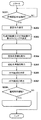
図3は、カメラ本体120が実行する連続撮影処理のフローチャートである。本フローチャートにおいて、各ステップの処理は、特に断らない限り、カメラMPU125がROM125aに格納されたプログラムに従ってカメラ本体120の各部を制御したりレンズMPU117と通信したりすることにより実現される。
FIG. 3 is a flowchart of a continuous shooting process executed by the
S301で、カメラMPU125は、連続撮影の開始が指示されるまで待ち、連続撮影の開始が指示されると、処理をS302へ進める。ユーザは、例えば操作スイッチ群127の操作などにより、カメラ本体120に対して連続撮影の開始を指示することができる。S302で、カメラMPU125は、シャッター秒時Tv、絞り値Fなどの撮影条件を設定する。S303で、カメラMPU125は、記録用画像及びAF用画像の表示タイミングを決定する。
In S301, the
ここで、図4及び図5を参照して、S303の処理の詳細について説明する。図4は、従来の連続撮影処理のタイミングチャートを示し、図5は、第1の実施形態に係る連続撮影処理のタイミングチャートを示す。 Here, the details of the processing of S303 will be described with reference to FIGS. 4 and 5. FIG. 4 shows a timing chart of the conventional continuous shooting process, and FIG. 5 shows a timing chart of the continuous shooting process according to the first embodiment.
図4及び図5において、斜線のブロックは、記録用画像に関連する処理を示しており、白色のブロックは、AF用画像に関連する処理を示している。Tr1、Tr2は、それぞれ記録用画像及びAF用画像の露光、読出し、画像取得の時間(露光開始から取得完了までに要する時間)を示している。tr1、tr1’は、記録用画像の露光開始時刻を示しており、tr2は、AF用画像の露光開始時刻を示している。td1、td1’は、記録用画像の表示開始時刻を示しており、td2は、AF用画像の表示開始時刻を示している。 In FIGS. 4 and 5, the shaded blocks indicate the processes related to the recording image, and the white blocks indicate the processes related to the AF image. Tr1 and Tr2 indicate the exposure, reading, and image acquisition time (time required from the start of exposure to the completion of acquisition) of the recording image and the AF image, respectively. tr1 and tr1'indicate the exposure start time of the recording image, and tr2 indicates the exposure start time of the AF image. td1 and td1'indicate the display start time of the recording image, and td2 indicates the display start time of the AF image.
また、図4において、Td1_0は、記録用画像の表示時間を示しており、Td2_0は、AF用画像の表示時間を示している。図5において、Td1は、記録用画像の表示時間を示しており、Td2は、AF用画像の表示時間を示している。図5のΔTd1は、記録用画像の表示遅延時間(記録用画像の取得完了から表示開始までの時間)を示しており、ΔTd2は、AF用画像の表示遅延時間(AF用画像の取得完了から表示開始までの時間)を示している。なお、図5の例では、ΔTd1=0であるが、本実施形態はΔTd1=0に限定されない。図5のt11〜t18は時刻を表している。なお、図5では時刻をt18まで示しているが、後述するS308において連続撮影を継続すると判定されれば、時刻t18以降も連続撮影処理が継続する。 Further, in FIG. 4, Td1_0 indicates the display time of the recording image, and Td2_0 indicates the display time of the AF image. In FIG. 5, Td1 indicates the display time of the recording image, and Td2 indicates the display time of the AF image. ΔTd1 in FIG. 5 indicates the display delay time of the recording image (time from the completion of acquisition of the recording image to the start of display), and ΔTd2 is the display delay time of the AF image (from the completion of acquisition of the AF image). The time until the display starts) is shown. In the example of FIG. 5, ΔTd1 = 0, but this embodiment is not limited to ΔTd1 = 0. T11 to t18 in FIG. 5 represent the time. Although the time is shown up to t18 in FIG. 5, if it is determined in S308 described later that continuous shooting is to be continued, the continuous shooting process will continue after the time t18.
S303では、カメラMPU125は、記録用画像及びAF用画像の表示タイミングを決定する。より具体的には、カメラMPU125は、記録用画像の表示遅延時間ΔTd1、AF用画像の表示遅延時間ΔTd2、記録用画像の表示時間Td1、AF用画像の表示時間Td2を決定する。なお、本実施形態では、記録用画像の表示時間Td1はAF用画像の表示開始時刻td2まで継続し、AF用画像の表示時間Td2は記録用画像の表示開始時刻td1’まで継続するものとする。従って、表示遅延時間ΔTd1,ΔTd2が決まれば表示時間Td1,Td2も自動的に決まるため、カメラMPU125は、実質的には表示遅延時間ΔTd1,ΔTd2のみを決定すればよい。
In S303, the
図5の例では、カメラMPU125は、AF用画像の露光開始時刻tr2から表示開始時刻td2までの時間(td2−tr2=Tr2+ΔTd2)が、記録用画像の露光開始時刻tr1から表示開始時刻td1までの時間(td1−tr1=Tr1+ΔTd1)と等しくなるように、表示遅延時間ΔTd1,ΔTd2を決定する。そして、カメラMPU125は、表示遅延時間ΔTd1,ΔTd2に基づき、表示時間Td1,Td2を算出する。具体的には、カメラMPU125は、S302で設定した撮影条件に基づき、記録用画像及びAF用画像それぞれの露光開始から取得完了までの時間Tr1,Tr2を取得する。そして、カメラMPU125は、記録用画像の表示遅延時間ΔTd1を0に決定する(前述の通り、0以外でもよい)。そして、カメラMPU125は、下記の式1に従ってAF用画像の表示遅延時間ΔTd2を算出する。
Tr2+ΔTd2=Tr1+ΔTd1
ΔTd2=Tr1+ΔTd1−Tr2=Tr1−Tr2
・・・(1)
In the example of FIG. 5, in the
Tr2 + ΔTd2 = Tr1 + ΔTd1
ΔTd2 = Tr1 + ΔTd1-Tr2 = Tr1-Tr2
... (1)
次に、カメラMPU125は、記録用画像及びAF用画像の表示時間Td1,Td2を算出する。具体的には、カメラMPU125は、S302で設定した撮影条件に基づき、表示遅延時間ΔTd1,ΔTd2が存在しない場合の表示時間Td1_0,Td2_0(図4参照)を取得する。そして、カメラMPU125は、下記の式2に従って表示時間Td1,Td2を算出する。
Td1=Td1_0+(ΔTd2−ΔTd1)=Td1_0+ΔTd2
Td2=Td2_0+(ΔTd1−ΔTd2)=Td1_0−ΔTd2
・・・(2)
Next, the
Td1 = Td1_0 + (ΔTd2-ΔTd1) = Td1_0 + ΔTd2
Td2 = Td2_0 + (ΔTd1-ΔTd2) = Td1_0-ΔTd2
... (2)
S304からS307では、記録用画像及びAF用画像が順次取得され、S303で決定された表示タイミングに従って順次表示される。S304からS307の処理は、S308において連続撮影を継続しないと判定されるまで繰り返し実行される。また、S304からS307の処理と並行して、カメラMPU125は、記録用画像をメモリ128に記録し、また、AF用画像に基づいて撮像面位相差AFを行う。
In S304 to S307, the recording image and the AF image are sequentially acquired, and are sequentially displayed according to the display timing determined in S303. The processes of S304 to S307 are repeatedly executed until it is determined in S308 that continuous photographing is not continued. Further, in parallel with the processing of S304 to S307, the
S304で、カメラMPU125は、記録用画像を取得するための撮像制御(撮像素子122の露光・読出しなど)を行う。撮像素子122の露光は、ローリングシャッター、又はグローバルシャッターを用いて行われる。記録用画像の取得は、露光開始時刻tr1(t11)から取得完了時刻t12までの間に行われる。
In S304, the
S305で、カメラMPU125は、S303で決定した表示遅延時間ΔTd1及び表示時間Td1に基づき、記録用画像の表示開始時刻及び表示時間を設定して、表示部126に対して表示指示を出す。具体的には、カメラMPU125は、時刻t12で記録用画像の表示を開始して、時刻t16まで表示を継続させる表示指示を出す。
In S305, the
なお、厳密に言えば、S304及びS305の間に、カメラMPU125は、取得した記録用画像を、表示部126での表示に適したデータ形式に変換する処理を行う。この変換処理に要する時間は、記録用画像の露光開始から取得完了までに要する時間Tr1に含めて扱うことができる。また、S305では、取得した記録用画像を適切なデータ形式に変換してメモリ128に記録する処理も並行して行われる。
Strictly speaking, between S304 and S305, the
S306で、カメラMPU125は、AF用画像を取得するための撮像制御(撮像素子122の露光・読出しなど)を行う。ここでの撮像制御は、AF用画像と記録用画像との相違に関係する部分を除き、S304における撮像制御と同様である。AF用画像の取得は、露光開始時刻tr2(t13)から、取得完了時刻t14までの間に行われる。
In S306, the
S307で、カメラMPU125は、S303で決定した表示遅延時間ΔTd2及び表示時間Td2に基づき、AF用画像の表示開始時刻及び表示時間を設定して、表示部126に対して表示指示を出す。具体的には、カメラMPU125は、時刻t16でAF用画像の表示を開始して、時刻t17まで表示を継続させる表示指示を出す。
In S307, the
なお、厳密に言えば、S306及びS307の間に、カメラMPU125は、取得したAF用画像を、表示部126での表示に適したデータ形式に変換する処理を行う。この変換処理に要する時間は、AF用画像の露光開始から取得完了までに要する時間Tr2に含めて扱うことができる。また、S307では、取得したAF用画像に基づく撮像面位相差AFも並行して行われる。
Strictly speaking, between S306 and S307, the
S308で、カメラMPU125は、連続撮影を継続するか否かを判定する。ユーザは、例えば操作スイッチ群127の操作などにより、連続撮影の継続と終了とを切り替えることができる。連続撮影を継続する場合、カメラMPU125は、処理をS304に戻し、そうでない場合、本フローチャートの処理は終了する。
In S308, the
以上説明したように、第1の実施形態によれば、カメラ本体120は、複数の画像を順次取得して順次表示する処理(表示制御)において、露光開始から取得完了までに要する時間が異なる記録用画像及びAF用画像を取得する。そして、カメラ本体120は、記録用画像及びその次に取得されたAF用画像を表示する際に、AF用画像の露光開始から表示開始までの時間が、記録用画像の露光開始から表示開始までの時間と等しくなるように制御する。これにより、ユーザに与える違和感を軽減することが可能となる。
As described above, according to the first embodiment, the
なお、上の説明では、AF用画像の露光開始から表示開始までの時間が、記録用画像の露光開始から表示開始までの時間と等しくなるように制御する構成について説明したが、本実施形態はこの構成に限定されない。AF用画像の露光開始から表示開始までの時間と、記録用画像の露光開始から表示開始までの時間との差の絶対値を少しでも小さくする制御を行えば、ユーザに与える違和感をある程度は軽減することができる。図4に示すように、従来は、差の絶対値が、記録用画像の露光開始から取得完了までの時間からAF用画像の露光開始から取得完了までの時間を引いた時間(Tr1−Tr2)に等しい。従って、カメラ本体120は、差の絶対値が、記録用画像の露光開始から取得完了までの時間からAF用画像の露光開始から取得完了までの時間を引いた時間未満になるように制御する。この場合、カメラ本体120は更に、AF用画像の露光開始から表示開始までの時間が、記録用画像の露光開始から表示開始までの時間以下となるように制御してもよい。このような制御により、ユーザに与える違和感をある程度は軽減することができる。
In the above description, a configuration is described in which the time from the start of exposure of the AF image to the start of display is controlled to be equal to the time from the start of exposure to the start of display of the recording image. It is not limited to this configuration. If the absolute value of the difference between the time from the start of exposure of the AF image to the start of display and the time from the start of exposure of the recording image to the start of display is controlled to be as small as possible, the discomfort given to the user can be reduced to some extent. can do. As shown in FIG. 4, conventionally, the absolute value of the difference is the time obtained by subtracting the time from the start of exposure of the AF image to the completion of acquisition from the time from the start of exposure to the completion of acquisition of the recording image (Tr1-Tr2). be equivalent to. Therefore, the
[第2の実施形態]
第2の実施形態では、記録用画像及びAF用画像の表示開始時刻の間隔を等しくすることによりユーザに与える違和感を軽減する構成について説明する。本実施形態において、撮像装置(図1)の基本的な構成は第1の実施形態と同様である。以下、主に第1の実施形態と異なる点について説明する。
[Second Embodiment]
In the second embodiment, a configuration for reducing the discomfort given to the user by making the intervals between the display start times of the recording image and the AF image equal to each other will be described. In the present embodiment, the basic configuration of the image pickup apparatus (FIG. 1) is the same as that of the first embodiment. Hereinafter, the points different from the first embodiment will be mainly described.
第2の実施形態では、図3のS303において記録用画像及びAF用画像の表示タイミングを決定する処理が、第1の実施形態と異なる。図6は、第2の実施形態に係る連続撮影処理のタイミングチャートを示す。図6は、図5と比べて、記録用画像及びAF用画像の表示時間Td1,Td2と、AF用画像の表示開始時刻td2とが異なる。図6のt21〜t27は時刻を表している。なお、図6では時刻をt27まで示しているが、第1の実施形態と同様、S308において連続撮影を継続すると判定されれば、時刻t27以降も連続撮影処理が継続する。第2の実施形態では、カメラMPU125は、記録用画像の表示開始時刻td1からAF用画像の表示開始時刻td2までの時間が、AF用画像の表示開始時刻td2から記録用画像の表示開始時刻td1’までの時間と等しくなるように制御する。
In the second embodiment, the process of determining the display timing of the recording image and the AF image in S303 of FIG. 3 is different from that of the first embodiment. FIG. 6 shows a timing chart of the continuous shooting process according to the second embodiment. In FIG. 6, the display times Td1 and Td2 of the recording image and the AF image and the display start time td2 of the AF image are different from those in FIG. T21 to t27 in FIG. 6 represent the time. Although the time is shown up to t27 in FIG. 6, the continuous shooting process continues after the time t27 if it is determined in S308 that the continuous shooting is continued, as in the first embodiment. In the second embodiment, in the
図3のS301及びS302の処理は、第1の実施形態と同様である。S303で、カメラMPU125は、記録用画像の表示遅延時間ΔTd1、AF用画像の表示遅延時間ΔTd2、記録用画像の表示時間Td1、AF用画像の表示時間Td2を決定する。具体的には、カメラMPU125は、記録用画像の表示遅延時間ΔTd1を決定する。ここでは、第1の実施形態と同様、ΔTd1=0であるものとする。そして、カメラMPU125は、S302で設定した撮影条件に基づき、記録用画像の取得完了時刻にΔTd1を加えることにより、記録用画像の表示開始時刻td1,td1’を算出する。そして、カメラMPU125は、AF用画像の表示開始時刻td2を、記録用画像の表示開始時刻td1,td1’の中間に決定する。そして、カメラMPU125は、表示開始時刻td1,td2,td1’に基づき、AF用画像の表示遅延時間ΔTd2、記録用画像の表示時間Td1、AF用画像の表示時間Td2を算出する。
The processing of S301 and S302 in FIG. 3 is the same as that of the first embodiment. In S303, the
S304以降の処理は、S303で決定された表示タイミングが第1の実施形態と異なる点を除き、第1の実施形態と同様である。図6に示すように、記録用画像及びAF用画像が、等しい間隔で順次表示される。 The processing after S304 is the same as that of the first embodiment except that the display timing determined in S303 is different from that of the first embodiment. As shown in FIG. 6, the recording image and the AF image are sequentially displayed at equal intervals.
以上説明したように、第2の実施形態によれば、カメラ本体120は、記録用画像の表示開始時刻td1からAF用画像の表示開始時刻td2までの時間が、AF用画像の表示開始時刻td2から記録用画像の表示開始時刻td1’までの時間と等しくなるように制御する。これにより、複数の画像の表示間隔が均等になり、ユーザに与える違和感を軽減することが可能となる。
As described above, according to the second embodiment, in the
[その他の実施形態]
本発明は、上述の実施形態の1以上の機能を実現するプログラムを、ネットワーク又は記憶媒体を介してシステム又は装置に供給し、そのシステム又は装置のコンピュータにおける1つ以上のプロセッサーがプログラムを読出し実行する処理でも実現可能である。また、1以上の機能を実現する回路(例えば、ASIC)によっても実現可能である。
[Other Embodiments]
The present invention supplies a program that realizes one or more functions of the above-described embodiment to a system or device via a network or storage medium, and one or more processors in the computer of the system or device reads and executes the program. It can also be realized by the processing to be performed. It can also be realized by a circuit (for example, ASIC) that realizes one or more functions.
100…レンズユニット、120…カメラ本体、122…撮像素子、123…撮像素子駆動回路、124…画像処理回路、125…カメラMPU、126…表示部、127…操作スイッチ群 100 ... lens unit, 120 ... camera body, 122 ... image sensor, 123 ... image sensor drive circuit, 124 ... image processing circuit, 125 ... camera MPU, 126 ... display unit, 127 ... operation switch group
Claims (8)
前記撮像素子を用いた露光及び読み出しを制御することで、露光による蓄積電荷の読み出しに必要な時間が異なる第1の画像と第2の画像を取得する撮像制御手段と、
前記撮像素子から読み出された画像の表示手段への表示を制御する表示制御手段と、
を備え、
前記第2の画像は、前記第1の画像よりも解像度が低く、読み出しに必要な時間が短く、
前記表示制御手段は、前記表示手段に前記第1の画像と前記第2の画像とを周期的に順に表示させる際に、前記第1の画像及び前記第2の画像の読み出しに必要な時間の差に基づいて、前記第2の画像の読み出し完了から前記表示手段への表示開始までの第1の時間を設定し、
前記第1の時間は、前記第1の画像の読み出し完了から前記表示手段への表示開始までの第2の時間より長い
ことを特徴とする撮像装置。 Image sensor and
An image pickup control means for acquiring a first image and a second image in which the time required for reading out the accumulated charge by the exposure is different by controlling the exposure and the readout using the image pickup element.
A display control means for controlling the display of an image read from the image sensor on the display means, and a display control means.
With
The second image has a lower resolution than the first image and requires less time to read.
When the display control means periodically displays the first image and the second image in order on the display means, the time required for reading the first image and the second image is Based on the difference, the first time from the completion of reading the second image to the start of display on the display means is set.
The image pickup apparatus, characterized in that the first time is longer than the second time from the completion of reading the first image to the start of display on the display means.
ことを特徴とする請求項1に記載の撮像装置。 When displaying the first image and the second image, the display control means displays the time required from the start of reading the second image to the display from the start of reading the first image. The image pickup apparatus according to claim 1, wherein the time required is controlled so as to be less than or equal to the time required.
ことを特徴とする請求項1に記載の撮像装置。 When the display control means displays the first image and the second image, the display time of the second image on the display means is displayed on the display means of the first image. The image pickup apparatus according to claim 1, wherein the image pickup apparatus is controlled so as to be substantially equal to the time.
ことを特徴とする請求項1乃至3のいずれか1項に記載の撮像装置。 The imaging device according to any one of claims 1 to 3, wherein the display control means periodically and alternately displays the first image and the second image.
ことを特徴とする請求項1乃至4のいずれか1項に記載の撮像装置。 The imaging control means is characterized in that the distance between the exposure centers of gravity of the first image and the exposure center of gravity of the second image, which are continuously acquired by using the image pickup element, is controlled to be substantially the same. Item 2. The image pickup apparatus according to any one of Items 1 to 4.
前記第1の画像は、記録用の画像データであり、
前記第2の画像は、視差を持つ焦点検出用の画像データである
ことを特徴とする請求項1乃至5のいずれか1項に記載の撮像装置。 The image pickup device has a plurality of focus detection pixels that receive light flux that passes through different pupil region regions of the photographing optical system.
The first image is image data for recording, and is
The image pickup apparatus according to any one of claims 1 to 5, wherein the second image is image data for focus detection having parallax.
前記撮像素子を用いた露光及び読み出しを制御することで、露光による蓄積電荷の読み出しに必要な時間が異なる第1の画像と第2の画像を取得する撮像制御工程と、
前記撮像素子から読み出された画像の表示手段への表示を制御する表示制御工程と、
を備え、
前記第2の画像は、前記第1の画像よりも解像度が低く、読み出しに必要な時間が短く、
前記表示制御工程では、前記表示手段に前記第1の画像と前記第2の画像とを周期的に順に表示させる際に、前記第1の画像及び前記第2の画像の読み出しに必要な時間の差に基づいて、前記第2の画像の読み出し完了から前記表示手段への表示開始までの第1の時間を設定し、
前記第1の時間は、前記第1の画像の読み出し完了から前記表示手段への表示開始までの第2の時間より長い
ことを特徴とする制御方法。 It is a control method executed by an image pickup device equipped with an image pickup device.
An image pickup control step of acquiring a first image and a second image in which the time required for reading out the accumulated charge by the exposure is different by controlling the exposure and the reading using the image sensor.
A display control step for controlling the display of the image read from the image sensor on the display means, and
With
The second image has a lower resolution than the first image and requires less time to read.
In the display control step, when the display means periodically displays the first image and the second image in order, the time required to read the first image and the second image is Based on the difference, the first time from the completion of reading the second image to the start of display on the display means is set.
The control method, characterized in that the first time is longer than the second time from the completion of reading the first image to the start of display on the display means.
Priority Applications (3)
| Application Number | Priority Date | Filing Date | Title |
|---|---|---|---|
| JP2017125585A JP6917803B2 (en) | 2017-06-27 | 2017-06-27 | Imaging equipment, control methods, and programs |
| US16/012,983 US10694127B2 (en) | 2017-06-27 | 2018-06-20 | Image capturing apparatus, control method, and storage medium for reducing the sense of incongruity felt by a laser |
| CN201810680812.3A CN109151265B (en) | 2017-06-27 | 2018-06-27 | Image pickup apparatus, control method, and storage medium |
Applications Claiming Priority (1)
| Application Number | Priority Date | Filing Date | Title |
|---|---|---|---|
| JP2017125585A JP6917803B2 (en) | 2017-06-27 | 2017-06-27 | Imaging equipment, control methods, and programs |
Publications (3)
| Publication Number | Publication Date |
|---|---|
| JP2019009694A JP2019009694A (en) | 2019-01-17 |
| JP2019009694A5 JP2019009694A5 (en) | 2020-08-06 |
| JP6917803B2 true JP6917803B2 (en) | 2021-08-11 |
Family
ID=64693820
Family Applications (1)
| Application Number | Title | Priority Date | Filing Date |
|---|---|---|---|
| JP2017125585A Active JP6917803B2 (en) | 2017-06-27 | 2017-06-27 | Imaging equipment, control methods, and programs |
Country Status (3)
| Country | Link |
|---|---|
| US (1) | US10694127B2 (en) |
| JP (1) | JP6917803B2 (en) |
| CN (1) | CN109151265B (en) |
Families Citing this family (2)
| Publication number | Priority date | Publication date | Assignee | Title |
|---|---|---|---|---|
| WO2019207568A1 (en) * | 2018-04-23 | 2019-10-31 | ContinUse Biometrics Ltd. | System and method for monitoring a sample |
| CN113824902A (en) * | 2021-09-30 | 2021-12-21 | 杭州海康汽车软件有限公司 | Method, device, system, equipment and medium for determining time delay of infrared camera system |
Family Cites Families (14)
| Publication number | Priority date | Publication date | Assignee | Title |
|---|---|---|---|---|
| KR100667444B1 (en) * | 1999-08-17 | 2007-01-10 | 어플라이드 비전 시스템즈, 인코포레이티드 | Improved dynamic range video camera, recording system, and recording method |
| JP2004134867A (en) | 2002-10-08 | 2004-04-30 | Canon Inc | Solid-state imaging apparatus, drive method thereof, and imaging system |
| CN100350794C (en) * | 2002-12-02 | 2007-11-21 | 奥林巴斯株式会社 | Image pickup apparatus |
| JP2009111518A (en) * | 2007-10-26 | 2009-05-21 | Casio Comput Co Ltd | Imaging apparatus, image reproducing unit and program thereof, and data structure of image file |
| JP5157757B2 (en) * | 2008-08-29 | 2013-03-06 | 株式会社ニコン | Electronic camera |
| JP2011151687A (en) * | 2010-01-22 | 2011-08-04 | Canon Inc | Image reading apparatus, method of controlling the same, and program |
| JP2011223426A (en) * | 2010-04-13 | 2011-11-04 | Panasonic Corp | Imaging apparatus |
| JP5630146B2 (en) * | 2010-08-23 | 2014-11-26 | ソニー株式会社 | Imaging apparatus, imaging apparatus control method, and program. |
| KR20130003139A (en) * | 2011-06-30 | 2013-01-09 | 삼성디스플레이 주식회사 | Method of displaying a stereoscopic image and stereoscopic image display device |
| JP5835996B2 (en) * | 2011-08-08 | 2015-12-24 | オリンパス株式会社 | Imaging device |
| CN104620572B (en) * | 2012-09-19 | 2016-06-29 | 富士胶片株式会社 | Camera head and control method thereof |
| WO2014054498A1 (en) * | 2012-10-05 | 2014-04-10 | 富士フイルム株式会社 | Imaging device and image display method |
| JP6300076B2 (en) * | 2014-01-31 | 2018-03-28 | カシオ計算機株式会社 | Imaging apparatus, imaging method, and program |
| CN106775403B (en) * | 2016-12-14 | 2020-03-03 | 北京小米移动软件有限公司 | Method and device for acquiring stuck information |
-
2017
- 2017-06-27 JP JP2017125585A patent/JP6917803B2/en active Active
-
2018
- 2018-06-20 US US16/012,983 patent/US10694127B2/en active Active
- 2018-06-27 CN CN201810680812.3A patent/CN109151265B/en active Active
Also Published As
| Publication number | Publication date |
|---|---|
| US10694127B2 (en) | 2020-06-23 |
| JP2019009694A (en) | 2019-01-17 |
| CN109151265B (en) | 2021-01-05 |
| CN109151265A (en) | 2019-01-04 |
| US20180376086A1 (en) | 2018-12-27 |
Similar Documents
| Publication | Publication Date | Title |
|---|---|---|
| JP6405243B2 (en) | Focus detection apparatus and control method thereof | |
| US20130010078A1 (en) | Stereoscopic image taking apparatus | |
| US9681037B2 (en) | Imaging apparatus and its control method and program | |
| US8823778B2 (en) | Imaging device and imaging method | |
| US10986262B2 (en) | Imaging apparatus, control method, and non-transitory storage medium | |
| JP2011022386A (en) | Imaging apparatus and control method therefor | |
| JP6843604B2 (en) | Information processing device and information processing method | |
| JP6289017B2 (en) | Imaging apparatus, control method therefor, program, and storage medium | |
| JP5750551B2 (en) | Apparatus and method for measuring distance of multiple subjects | |
| US8970754B2 (en) | Image capturing apparatus and method for controlling the image capturing apparatus | |
| JP2012113171A (en) | Imaging device and control method therefor | |
| US20130314500A1 (en) | Stereoscopic imaging apparatus | |
| US8902294B2 (en) | Image capturing device and image capturing method | |
| US9077979B2 (en) | Stereoscopic image capture device and method | |
| JP6917803B2 (en) | Imaging equipment, control methods, and programs | |
| JP2017044821A (en) | Image-capturing device and control method therefor, program, and storage medium | |
| JP2012124650A (en) | Imaging apparatus, and imaging method | |
| JP6720037B2 (en) | Image processing device, imaging device, image processing method, and image processing program | |
| JP7307837B2 (en) | IMAGING DEVICE AND CONTROL METHOD THEREOF, PROGRAM, STORAGE MEDIUM | |
| JP2016006463A (en) | Imaging device and control method therefor | |
| JP2024008154A (en) | Image processing device, display device, and image processing method | |
| JP6285639B2 (en) | Image processing apparatus, imaging apparatus, control method, and program | |
| JP2018170608A (en) | Imaging apparatus, control method of the same, and program | |
| JP2019139043A (en) | Imaging apparatus and method for controlling the same | |
| JP2016099416A (en) | Imaging apparatus |
Legal Events
| Date | Code | Title | Description |
|---|---|---|---|
| A521 | Request for written amendment filed |
Free format text: JAPANESE INTERMEDIATE CODE: A523 Effective date: 20200619 |
|
| A621 | Written request for application examination |
Free format text: JAPANESE INTERMEDIATE CODE: A621 Effective date: 20200619 |
|
| RD01 | Notification of change of attorney |
Free format text: JAPANESE INTERMEDIATE CODE: A7421 Effective date: 20210103 |
|
| A521 | Request for written amendment filed |
Free format text: JAPANESE INTERMEDIATE CODE: A523 Effective date: 20210113 |
|
| A977 | Report on retrieval |
Free format text: JAPANESE INTERMEDIATE CODE: A971007 Effective date: 20210427 |
|
| TRDD | Decision of grant or rejection written | ||
| A01 | Written decision to grant a patent or to grant a registration (utility model) |
Free format text: JAPANESE INTERMEDIATE CODE: A01 Effective date: 20210621 |
|
| A61 | First payment of annual fees (during grant procedure) |
Free format text: JAPANESE INTERMEDIATE CODE: A61 Effective date: 20210720 |
|
| R151 | Written notification of patent or utility model registration |
Ref document number: 6917803 Country of ref document: JP Free format text: JAPANESE INTERMEDIATE CODE: R151 |