JP6917785B2 - Golf club head - Google Patents
Golf club head Download PDFInfo
- Publication number
- JP6917785B2 JP6917785B2 JP2017111140A JP2017111140A JP6917785B2 JP 6917785 B2 JP6917785 B2 JP 6917785B2 JP 2017111140 A JP2017111140 A JP 2017111140A JP 2017111140 A JP2017111140 A JP 2017111140A JP 6917785 B2 JP6917785 B2 JP 6917785B2
- Authority
- JP
- Japan
- Prior art keywords
- wall surface
- golf club
- club head
- head
- intermediate member
- Prior art date
- Legal status (The legal status is an assumption and is not a legal conclusion. Google has not performed a legal analysis and makes no representation as to the accuracy of the status listed.)
- Active
Links
Images


Classifications
-
- A—HUMAN NECESSITIES
- A63—SPORTS; GAMES; AMUSEMENTS
- A63B—APPARATUS FOR PHYSICAL TRAINING, GYMNASTICS, SWIMMING, CLIMBING, OR FENCING; BALL GAMES; TRAINING EQUIPMENT
- A63B60/00—Details or accessories of golf clubs, bats, rackets or the like
- A63B60/54—Details or accessories of golf clubs, bats, rackets or the like with means for damping vibrations
-
- A—HUMAN NECESSITIES
- A63—SPORTS; GAMES; AMUSEMENTS
- A63B—APPARATUS FOR PHYSICAL TRAINING, GYMNASTICS, SWIMMING, CLIMBING, OR FENCING; BALL GAMES; TRAINING EQUIPMENT
- A63B53/00—Golf clubs
- A63B53/04—Heads
- A63B53/045—Strengthening ribs
- A63B53/0454—Strengthening ribs on the rear surface of the impact face plate
-
- A—HUMAN NECESSITIES
- A63—SPORTS; GAMES; AMUSEMENTS
- A63B—APPARATUS FOR PHYSICAL TRAINING, GYMNASTICS, SWIMMING, CLIMBING, OR FENCING; BALL GAMES; TRAINING EQUIPMENT
- A63B53/00—Golf clubs
- A63B53/04—Heads
- A63B53/0466—Heads wood-type
-
- A—HUMAN NECESSITIES
- A63—SPORTS; GAMES; AMUSEMENTS
- A63B—APPARATUS FOR PHYSICAL TRAINING, GYMNASTICS, SWIMMING, CLIMBING, OR FENCING; BALL GAMES; TRAINING EQUIPMENT
- A63B53/00—Golf clubs
- A63B53/04—Heads
- A63B53/047—Heads iron-type
-
- A—HUMAN NECESSITIES
- A63—SPORTS; GAMES; AMUSEMENTS
- A63B—APPARATUS FOR PHYSICAL TRAINING, GYMNASTICS, SWIMMING, CLIMBING, OR FENCING; BALL GAMES; TRAINING EQUIPMENT
- A63B60/00—Details or accessories of golf clubs, bats, rackets or the like
- A63B60/52—Details or accessories of golf clubs, bats, rackets or the like with slits
-
- A—HUMAN NECESSITIES
- A63—SPORTS; GAMES; AMUSEMENTS
- A63B—APPARATUS FOR PHYSICAL TRAINING, GYMNASTICS, SWIMMING, CLIMBING, OR FENCING; BALL GAMES; TRAINING EQUIPMENT
- A63B53/00—Golf clubs
- A63B53/04—Heads
- A63B53/047—Heads iron-type
- A63B2053/0479—Wedge-type clubs, details thereof
Description
本発明はゴルフクラブヘッドに関する。 The present invention relates to a golf club head.
打撃時のフェース部の傾斜やボールとの摩擦態様或いは打感を制御するために、フェース部の背後に空隙を設けたり、その空隙にゴムや樹脂を挿入することが提案されている(例えば特許文献1〜8)。
In order to control the inclination of the face portion at the time of hitting, the friction mode with the ball, or the feeling of hitting, it has been proposed to provide a gap behind the face portion or insert rubber or resin into the gap (for example, patent).
ヘッド上部に開口したスリットを形成すると、打撃時にフェース部の傾斜が大きくなって、打球の打ち出し角を増大させることができる。しかし、スリットを画定する前後の壁面が打撃時に衝突して異音を発生させる場合がある。その改善策として、スリットにゴムや樹脂などを挿入することは有効であるが、スリット内に適切に保持されていなければ目的とする機能を得られない場合がある。 When a slit opened in the upper part of the head is formed, the inclination of the face portion becomes large at the time of hitting, and the launch angle of the hit ball can be increased. However, the wall surfaces before and after defining the slit may collide with each other at the time of hitting to generate an abnormal noise. As a remedy, it is effective to insert rubber or resin into the slit, but if it is not properly held in the slit, the desired function may not be obtained.
本発明の目的は、スリットの形成により打球の打ち出し角を増大でき、かつ、スリットの挿入物をスリット内に保持することにある。 An object of the present invention is to increase the launch angle of a hit ball by forming a slit and to hold an insert of the slit in the slit.
本発明によれば、
ヘッド上部と、ヘッド底部と、前記ヘッド上部と前記ヘッド底部との間のフェース部と、を含むゴルフクラブヘッドであって、
前記フェース部よりもバック側において前記ヘッド上部に開口し、トウーヒール方向に延び、かつ、前記ヘッド底部へ向けて形成されたスリットと、
前記スリットに設けられ、前記スリットを画定する前記フェース部側の第一の壁面に当接する中間部材と、
前記第一の壁面から離間し、かつ、前記スリットを画定する前記バック側の第二の壁面の側から、前記中間部材を固定する固定部材と、
前記フェース部及び前記第一の壁面を含む第一の部分と、
前記第一の部分に対して前記スリットを挟んで前記バック側に位置し、前記第二の壁面を含む第二の部分と、を含み、
前記第二の部分は、前記第二の部分をフェース−バック方向に貫通して前記第二の壁面に開口した穴を含み、
前記中間部材の一部が前記穴に挿入され、
前記固定部材は前記穴に取り付けられる、
ことを特徴とするゴルフクラブヘッドが提供される。
According to the present invention
A golf club head including a head upper portion, a head bottom portion, and a face portion between the head upper portion and the head bottom portion.
A slit that opens to the upper part of the head on the back side of the face portion, extends in the toe-heel direction, and is formed toward the bottom portion of the head.
An intermediate member provided in the slit and in contact with the first wall surface on the face portion side that defines the slit,
A fixing member that is separated from the first wall surface and fixes the intermediate member from the side of the second wall surface on the back side that defines the slit.
A first portion including the face portion and the first wall surface, and
A second portion located on the back side of the first portion with the slit in between and including the second wall surface, and includes the second portion.
The second portion includes a hole that penetrates the second portion in the face-back direction and opens in the second wall surface.
A part of the intermediate member is inserted into the hole,
The fixing member is attached to the hole,
A golf club head characterized by that is provided.
本発明によれば、スリットの形成により打球の打ち出し角を増大でき、かつ、スリットの挿入物をスリット内に保持することができる。 According to the present invention, the launch angle of the hit ball can be increased by forming the slit, and the insert of the slit can be held in the slit.
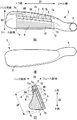
図1(A)〜図3(B)を参照して本発明の一実施形態に係るゴルフクラブヘッド1を説明する。図1(A)はゴルフクラブヘッド1の正面図、図1(B)は背面図、図2(A)は平面図、図2(B)は底面図、図2(C)は図1(B)のI−I線断面図である。図3(A)及び図3(B)は図2(C)のA部拡大図であり、図3(B)は分解図である。図中、矢印D1はトウ−ヒール方向を、矢印D2は上下方向を、矢印D3はフェース−バック方向をそれぞれ示す。
The golf club head 1 according to the embodiment of the present invention will be described with reference to FIGS. 1 (A) to 3 (B). 1 (A) is a front view of the
ゴルフクラブヘッド1は、アイアン型のゴルフクラブヘッドである。本発明はロングアイアン、ミドルアイアン、ショートアイアン、ウェッジのいずれにも適用可能であるが、打ち出し角の増大の点でロングアイアン、ミドルアイアンに好適である。また、本発明はアイアン型のゴルフクラブヘッドに限らず、ユーティリティ型(ハイブリッド型)、ウッド型のゴルフクラブヘッドにも適用可能である。
The
ゴルフクラブヘッド1は、ヘッド上部2、ヘッド底部3、フェース部4、ホゼル部5及びバック部6を含む。ヘッド上部2はゴルフクラブヘッド1の上面を形成し、ヘッド底部3はソール部であり、ゴルフクラブヘッド1の底面を形成する。ヘッド上部2とヘッド底部3との間のヘッド正面部は、トウ側部分1a、ヒール側部分1b、及び、トウ側部分1aとヒール側部分1bとの間のフェース部4を含む。フェース部4はゴルフボールの打撃面を形成する。フェース部4は本実施形態の場合、平面の打撃面を形成しており、D1方向に延びるスコアライン41が、D2方向に複数形成されている。フェース部4と、トウ側部分1a及びヒール側部分1bとは、例えば、本実施形態のようにスコアライン41が形成されている領域か、あるいは、表面処理が異なる領域か否かで区別することができる。表面処理としては、例えば、フェース部4にはブラスト処理等が施され、トウ側部分1a及びヒール側部分1bにはめっき処理、研磨仕上げ等が施される。バック部6はゴルフクラブヘッド1の背面を形成する。フェース部4及びバック部6はヘッド上部2とヘッド底部3との間に位置している。
The
ヘッド上部2、ヘッド底部3、フェース部4、ホゼル部5及びバック部6が、金属材料の単一部品に形成されている。しかし、フェース部4を含むフェース部材と、ヘッド上部2、ヘッド底部3、ホゼル部5及びバック部6を含む本体部材との二部品でこれらを形成することも可能である。
The head
ゴルフクラブヘッド1はスリット7を含む。スリット7は、フェース部4よりもバック部6の側においてヘッド上部2に開口した開口部7aを含み、開口部7aからフェース部4に沿ってヘッド底部3へ向けて形成されている。本実施形態の場合、スリット7はD1方向及びD3方向の双方向においてフェース部4と平行に形成されているが、フェース部4に対して傾きを有しつつ、フェース部4に沿って形成されていてもよい。
The
スリット7は、D3方向の隙間を形成する薄形の板形状の空間であり、フェース部4側の壁面(第一の壁面)7bと、バック部6側の壁面(第二の壁面)7cとによりD3方向の端部が画定されている。ゴルフクラブヘッド1を、スリット7を境界としてD3方向に区分けすると、壁面7bは、フェース部4を含む中実の部分10により形成されており、壁面7cは、バック部6を含む中実の部分11により形成されている。部分10と部分11はトウ側、ヒール側及びヘッド底部3側で接続されている。
The
壁面7bと壁面7cとは互いに対向して平行に形成されており、その間隔G(スリット7の隙間)は、例えば、1mm以上4mm以下である。
The
スリット7は、ヘッド底部3側の端部が底壁面7dにより画定された有底の空間である。開口部7aから底壁面7dまでの深さDPは、例えば、25mm以上50mm以下である。また、底壁面7dのD2方向の位置は、フェースセンタよりもヘッド底部3側の位置であることが好ましく、例えば、フェース部4の複数のスコアライン41のうち、最もヘッド底部3側のスコアライン41と同じか、低い位置に位置していてもよい。本実施形態の場合、最もヘッド底部3側のスコアライン41よりも低い位置に底壁面7dが位置している。また、底壁面7dからヘッド底部3までの最短距離tは、例えば、1mm以上5mm以下である。
The
ここで本実施形態におけるフェースセンタについて図4を参照して説明する。ゴルフクラブヘッド1を規定のライ角及びロフト角で接地させた状態を基準とする。最も長いスコラインのトウ−ヒール方向の長さをL1とし、その中央位置を通る仮想面をCL1とする。仮想面CL1上で接地面からヘッド上部2までの高さをL2とし、その中央位置を通る仮想面をCL2とする。仮想面CL1と仮想面CL2との交線とフェース部4との交点FCがフェースセンタである。
Here, the face center in the present embodiment will be described with reference to FIG. The state in which the
スリット7は、D1方向に延設されており、そのトウ側の端部が壁面7eで、ヒール側の端部が壁面7fで、それぞれ画定されている。本実施形態の場合、壁面7e、壁面7fは平行にD2方向に延びている。壁面7eと壁面7fとの離間距離Wは例えば、45mm以上60mm以下である。また、壁面7e、壁面7fのD1方向の位置は、例えば、フェース部4のD1方向の端部の位置と同じか、外側であってもよい。本実施形態の場合、壁面7e、壁面7fのD1方向の位置は、フェース部4のD1方向の端部の位置と同じ位置である。
The
このようなスリット7を設けたことで、ゴルフボールの打撃時にフェース部4(部分10)がバック部6側に後傾し易くなる。換言するとフェース部4のロフト角が大きくなる。このため打球の打ち出し角を増大できる。
By providing such a
打撃時にフェース部4が後傾する際、スリット7の隙間が狭くなり、壁面7bと壁面7cとが干渉する場合がある。その防止のため、本実施形態ではスリット7に中間部材8A及び8B(以下、区別しない場合は単に中間部材8という。)を設けている。中間部材8は、例えば、樹脂、繊維強化樹脂、ゴム、金属等で構成される。中間部材8は壁面7bに当接しており、壁面7bと壁面7cとが干渉することを規制する。
When the
スリット7には単一又は複数の中間部材が、スリット7の全体を埋めるように配置されていてもよいが、本実施形態の中間部材8は一部の部位のみ(2か所)に配置されている。これにより、打撃時にフェース部4が後傾し易くすることができる。
A single or a plurality of intermediate members may be arranged in the
また、フェース部4(部分10)は、D1方向で見るとトウ側で変形し易い傾向にある。ヒール側はD2方向の幅が狭く、また、ホゼル部5も存在するため、相対的に変形し難い。壁面7bと壁面7cとの干渉防止の観点では、フェース部4を図1(A)に示すようにD1方向でトウ側部T、中央部C、ヒール側部Hに三等分すると、中間部材8はトウ側部T又は中央部Cに設けることが好ましい。本実施形態の場合、中間部材8Aは中央部Cに、中間部材8Bはトウ側部Tに配置されている。
Further, the face portion 4 (part 10) tends to be easily deformed on the toe side when viewed in the D1 direction. Since the heel side has a narrow width in the D2 direction and the
また、フェース部4(部分10)は、D2方向で見るとヘッド上部2側で変形し易い傾向にある。スリット7は有底でヘッド上部2に開口しているからである。壁面7bと壁面7cとの干渉防止の観点では、中間部材8はD2方向でフェースセンタよりもヘッド上部2側に位置していることが好ましく、本実施形態の中間部材8A及び8Bはいずれもフェースセンタよりもヘッド上部2側に位置している。更に、フェース部4の上側の輪郭形状に対応して、中間部材8Bが中間部材8Aよりもヘッド上部2側に位置しており、少ない数又は小さな面積の中間部材8によって、壁面7bと壁面7cとの干渉防止性能を効果的に向上している。
Further, the face portion 4 (part 10) tends to be easily deformed on the
打撃時にスリット7の隙間が変化することから、中間部材8がスリット7から脱落したり、中間部材8の位置が変わることを防止する必要がある。本実施形態では、固定部材9A及び9B(以下、区別しない場合は単に固定部材9という。)により中間部材8A、8Bをそれぞれ固定している。本実施形態の場合、固定部材9A及び9Bは同様の構成であり、また、中間部材8A及び8Bは同様の構成である。図3(A)及び図3(B)を参照して、中間部材8A及び固定部材9Aの組の構造について説明するが、中間部材8B及び固定部材9Bの組の構造も同様である。
Since the gap of the
本実施形態の場合、固定部材9Aは部分11に形成した穴11aに係合する部材である。係合態様は、圧入、接着、溶接等、いずれでもよいが、本実施形態では着脱自在にする点でねじ構造としている。固定部材9Aは頭部91とねじ部92とを含むねじ部材であり、穴11aはねじ穴である。
In the case of the present embodiment, the fixing
穴11aは部分11をD3方向に貫通して壁面7cに開口した貫通穴である。中間部材8Aは円柱形状の部材であり、穴11aを挿通可能な直径を有している。図3(A)に示すように中間部材8Aは、そのフェース部4側の端部が壁面7bに当接し、バック部6側の端部は穴11aにその一部が挿入されている。このような本実施形態の構成は、組み付け性、交換容易性、脱落防止の点で有利である。
The
中間部材8Aを穴11aに挿入後、穴11aに固定部材9Aを螺着する。ねじ部92の先端が中間部材8Aを押し込み、中間部材8Aが壁面7bに当接する。中間部材8Aは壁面7bと固定部材9Aとの間で圧縮されてもよい。
After inserting the
以上の通り、本実施形態のゴルフクラブヘッド1によれば、スリット7の形成により打球の打ち出し角を増大でき、かつ、固定部材9によってスリット7の挿入物である中間部材8をスリット7内に保持することができる。
As described above, according to the
なお、本実施形態では、中間部材8と固定部材9の組を二つとしたが、一つでもよいし、三つ以上でもよい。 In the present embodiment, the number of pairs of the intermediate member 8 and the fixing member 9 is two, but it may be one or three or more.
また、中間部材8は固定部材9に接着等により一体化されていてもよい。例えば、ねじ部92の先端面に中間部材8のバック部6側の端面が接着されていてもよい。あるいは、ねじ部92の先端に該先端から突出する楔形の係合部を設け、中間部材8のバック部6側の端部に刺して一体化してもよい。これにより、ヘッドに対する中間部材8及び固定部材9の組み付け性、交換容易性を更に向上できる。
Further, the intermediate member 8 may be integrated with the fixing member 9 by adhesion or the like. For example, the end surface of the intermediate member 8 on the
中間部材8の弾性変形特性によって、打撃時のフェース部4の後傾度合を制御することができる。例えば、ハードヒッターに対しては変形量の小さい硬い材料が中間部材8に適している。逆に、比較的に非力なゴルファに対しては変形量の大きい軟らかい材料が中間部材8に適している。そこで、中間部材8は複数種類の中間部材の中から選択可能であってもよい。本実施形態では、中間部材8及び固定部材9がヘッドから着脱自在な構成であるため、ゴルファが自分の好みにあった種類の中間部材8を選択することも可能である。また、本実施形態のように、中間部材8及び固定部材9の組が複数組ある場合、中間部材8の種類が異なる組があってもよく、この場合も、中間部材8の種類をゴルファが選択可能であってもよい。
The degree of backward inclination of the
また、スリット7にごみが侵入することを防止するため、開口部7aにカバーを設けてもよい。
Further, in order to prevent dust from entering the
1 ゴルフクラブヘッド、2 ヘッド上部、3、ヘッド底部、4 フェース部、7 スリット、8A 中間部材、9A 固定部材 1 Golf club head, 2 Head top, 3, Head bottom, 4 Face, 7 Slits, 8A intermediate member, 9A fixing member
Claims (6)
前記フェース部よりもバック側において前記ヘッド上部に開口し、トウーヒール方向に延び、かつ、前記ヘッド底部へ向けて形成されたスリットと、
前記スリットに設けられ、前記スリットを画定する前記フェース部側の第一の壁面に当接する中間部材と、
前記第一の壁面から離間し、かつ、前記スリットを画定する前記バック側の第二の壁面の側から、前記中間部材を固定する固定部材と、
前記フェース部及び前記第一の壁面を含む第一の部分と、
前記第一の部分に対して前記スリットを挟んで前記バック側に位置し、前記第二の壁面を含む第二の部分と、を含み、
前記第二の部分は、前記第二の部分をフェース−バック方向に貫通して前記第二の壁面に開口した穴を含み、
前記中間部材の一部が前記穴に挿入され、
前記固定部材は前記穴に取り付けられる、
ことを特徴とするゴルフクラブヘッド。 A golf club head including a head upper portion, a head bottom portion, and a face portion between the head upper portion and the head bottom portion.
A slit that opens to the upper part of the head on the back side of the face portion, extends in the toe-heel direction, and is formed toward the bottom portion of the head.
An intermediate member provided in the slit and in contact with the first wall surface on the face portion side that defines the slit,
A fixing member that is separated from the first wall surface and fixes the intermediate member from the side of the second wall surface on the back side that defines the slit.
A first portion including the face portion and the first wall surface, and
A second portion located on the back side of the first portion with the slit in between and including the second wall surface, and includes the second portion.
The second portion includes a hole that penetrates the second portion in the face-back direction and opens in the second wall surface.
A part of the intermediate member is inserted into the hole,
The fixing member is attached to the hole,
A golf club head that features that.
前記中間部材は、樹脂、繊維強化樹脂、ゴム、又は、金属である、
ことを特徴とするゴルフクラブヘッド。 The golf club head according to claim 1.
The intermediate member is a resin, a fiber reinforced resin, rubber, or a metal.
A golf club head that features that.
前記フェース部をトウ−ヒール方向にトウ側部、中央部、ヒール側部に三等分した場合、前記中間部材及び前記固定部材は前記トウ側部又は前記中央部に位置している、
ことを特徴とするゴルフクラブヘッド。 The golf club head according to claim 1 or 2.
When the face portion is divided into three equal parts in the toe-heel direction into a toe side portion, a central portion, and a heel side portion, the intermediate member and the fixing member are located at the toe side portion or the central portion.
A golf club head that features that.
前記中間部材及び前記固定部材は着脱自在であり、
前記中間部材は複数種類の中間部材の中から選択可能である、
ことを特徴とするゴルフクラブヘッド。 The golf club head according to any one of claims 1 to 3.
The intermediate member and the fixing member are removable and can be attached and detached.
The intermediate member can be selected from a plurality of types of intermediate members.
A golf club head that features that.
前記第一の壁面と前記第二の壁面とが平行である、
ことを特徴とするゴルフクラブヘッド。 The golf club head according to any one of claims 1 to 4.
The first wall surface and the second wall surface are parallel to each other.
A golf club head that features that.
前記第一の壁面と前記第二の壁面との間隔が1mm以上4mm以下である、
ことを特徴とするゴルフクラブヘッド。 The golf club head according to claim 5.
The distance between the first wall surface and the second wall surface is 1 mm or more and 4 mm or less.
A golf club head that features that.
Priority Applications (2)
| Application Number | Priority Date | Filing Date | Title |
|---|---|---|---|
| JP2017111140A JP6917785B2 (en) | 2017-06-05 | 2017-06-05 | Golf club head |
| US15/925,877 US10486044B2 (en) | 2017-06-05 | 2018-03-20 | Golf club head |
Applications Claiming Priority (1)
| Application Number | Priority Date | Filing Date | Title |
|---|---|---|---|
| JP2017111140A JP6917785B2 (en) | 2017-06-05 | 2017-06-05 | Golf club head |
Publications (3)
| Publication Number | Publication Date |
|---|---|
| JP2018201873A JP2018201873A (en) | 2018-12-27 |
| JP2018201873A5 JP2018201873A5 (en) | 2020-07-02 |
| JP6917785B2 true JP6917785B2 (en) | 2021-08-11 |
Family
ID=64459137
Family Applications (1)
| Application Number | Title | Priority Date | Filing Date |
|---|---|---|---|
| JP2017111140A Active JP6917785B2 (en) | 2017-06-05 | 2017-06-05 | Golf club head |
Country Status (2)
| Country | Link |
|---|---|
| US (1) | US10486044B2 (en) |
| JP (1) | JP6917785B2 (en) |
Families Citing this family (3)
| Publication number | Priority date | Publication date | Assignee | Title |
|---|---|---|---|---|
| US20220118328A1 (en) * | 2016-07-26 | 2022-04-21 | Acushnet Company | Golf club having a damping element for ball speed control |
| US20230042378A1 (en) * | 2016-07-26 | 2023-02-09 | Acushnet Company | Golf club having a damping element for ball speed control |
| KR200496190Y1 (en) * | 2022-02-08 | 2022-11-23 | 양건호 | Putter head with shock absorption function |
Family Cites Families (24)
| Publication number | Priority date | Publication date | Assignee | Title |
|---|---|---|---|---|
| US4027885A (en) * | 1974-06-06 | 1977-06-07 | Rogers Kenneth A | Golf iron manufacture |
| US4398965A (en) * | 1976-10-26 | 1983-08-16 | Pepsico, Inc. | Method of making iron golf clubs with flexible impact surface |
| JPS5365128A (en) | 1976-11-19 | 1978-06-10 | Heihachi Yoshioka | Method of producing head of iron golf club |
| US4252262A (en) | 1978-09-05 | 1981-02-24 | Igarashi Lawrence Y | Method for manufacturing a golf club |
| JPH01126269U (en) | 1988-02-20 | 1989-08-29 | ||
| US5255918A (en) * | 1989-06-12 | 1993-10-26 | Donald A. Anderson | Golf club head and method of forming same |
| JPH08164229A (en) * | 1994-12-16 | 1996-06-25 | Daiwa Golf Kk | Golf club head |
| JP3046011U (en) | 1997-08-06 | 1998-02-20 | 羚峰有限公司 | Golf club head |
| US7201669B2 (en) * | 2003-12-23 | 2007-04-10 | Nike, Inc. | Golf club head having a bridge member and a weight positioning system |
| CN100400127C (en) * | 2004-06-11 | 2008-07-09 | 复盛股份有限公司 | Golf club head structure with adjustable shock absorption |
| JP2006122544A (en) * | 2004-11-01 | 2006-05-18 | Kasco Corp | Iron golf club head |
| JP4677793B2 (en) | 2005-01-24 | 2011-04-27 | 横浜ゴム株式会社 | Iron golf club head and iron golf club |
| US7156752B1 (en) * | 2005-12-10 | 2007-01-02 | John Emmanuel Bennett | Gyroscopic golf club heads |
| TW200724197A (en) * | 2005-12-20 | 2007-07-01 | Head Usa Inc | Method and apparatus for elastic tailoring of golf club impact |
| JP4608437B2 (en) * | 2006-01-10 | 2011-01-12 | Sriスポーツ株式会社 | Golf club head |
| TW200927227A (en) * | 2007-12-25 | 2009-07-01 | Super Way Technology Co Ltd | Golf club head installed with the hollow gas-blocking, vibration-absorbing material and the air pressure function, and its manufacturing method |
| US8376873B2 (en) | 2009-11-11 | 2013-02-19 | Acushnet Company | Golf club head with replaceable face |
| US8758163B2 (en) * | 2010-04-12 | 2014-06-24 | Nike, Inc. | Iron type golf clubs and golf club heads having adjustable weighting features |
| US9731176B2 (en) * | 2014-12-31 | 2017-08-15 | Taylor Made Golf Company, Inc. | Golf club |
| US9802089B2 (en) * | 2013-03-15 | 2017-10-31 | Taylor Made Golf Company, Inc | Iron type golf club head and set |
| US9937395B2 (en) * | 2013-11-12 | 2018-04-10 | Taylor Made Golf Company, Inc. | Golf club |
| JP6446843B2 (en) | 2014-06-10 | 2019-01-09 | ブリヂストンスポーツ株式会社 | Golf club head |
| US9480888B1 (en) | 2014-12-16 | 2016-11-01 | Dillis V. Allen | Continued golf iron facetongue |
| US10086244B2 (en) * | 2016-07-26 | 2018-10-02 | Acushnet Company | Golf club having an elastomer element for ball speed control |
-
2017
- 2017-06-05 JP JP2017111140A patent/JP6917785B2/en active Active
-
2018
- 2018-03-20 US US15/925,877 patent/US10486044B2/en active Active
Also Published As
| Publication number | Publication date |
|---|---|
| US10486044B2 (en) | 2019-11-26 |
| US20180345106A1 (en) | 2018-12-06 |
| JP2018201873A (en) | 2018-12-27 |
Similar Documents
| Publication | Publication Date | Title |
|---|---|---|
| US9821203B2 (en) | Golf club head | |
| US9144717B2 (en) | Putter heads and putters | |
| JP5914459B2 (en) | Iron type golf club and golf club head with adjustable weighting features | |
| US7740545B2 (en) | Curved golf putter | |
| US7803064B2 (en) | Golf club head with multiple undercuts | |
| US4852880A (en) | Head structure for gold clubs | |
| KR101265396B1 (en) | Iron type golf clubs and golf club heads having weight containing and/or vibration damping insert members | |
| US20050014573A1 (en) | Golf iron | |
| US8663028B2 (en) | Golf club head | |
| KR20080034121A (en) | Golf club | |
| JP6917785B2 (en) | Golf club head | |
| US10537769B2 (en) | Golf club head | |
| US20200406109A1 (en) | Golf club head | |
| JP6827308B2 (en) | Golf club head | |
| US10441857B2 (en) | Iron golf club head | |
| US9993701B2 (en) | Golf club head | |
| JP6786267B2 (en) | Golf club head | |
| US20180015336A1 (en) | Golf club head | |
| JP7303050B2 (en) | Golf club | |
| JP5290722B2 (en) | Golf putter head | |
| CN211561763U (en) | Iron type golf club head and iron type golf club combination | |
| JP2006181212A (en) | Golf club set and golf clubs used for the same | |
| JP2020188857A (en) | grip | |
| JP2008246082A (en) | Golf club head |
Legal Events
| Date | Code | Title | Description |
|---|---|---|---|
| A621 | Written request for application examination |
Free format text: JAPANESE INTERMEDIATE CODE: A621 Effective date: 20200512 |
|
| A521 | Request for written amendment filed |
Free format text: JAPANESE INTERMEDIATE CODE: A523 Effective date: 20200525 |
|
| A977 | Report on retrieval |
Free format text: JAPANESE INTERMEDIATE CODE: A971007 Effective date: 20201225 |
|
| A131 | Notification of reasons for refusal |
Free format text: JAPANESE INTERMEDIATE CODE: A131 Effective date: 20210112 |
|
| RD02 | Notification of acceptance of power of attorney |
Free format text: JAPANESE INTERMEDIATE CODE: A7422 Effective date: 20210122 |
|
| A521 | Request for written amendment filed |
Free format text: JAPANESE INTERMEDIATE CODE: A523 Effective date: 20210302 |
|
| A02 | Decision of refusal |
Free format text: JAPANESE INTERMEDIATE CODE: A02 Effective date: 20210329 |
|
| A521 | Request for written amendment filed |
Free format text: JAPANESE INTERMEDIATE CODE: A523 Effective date: 20210430 |
|
| C60 | Trial request (containing other claim documents, opposition documents) |
Free format text: JAPANESE INTERMEDIATE CODE: C60 Effective date: 20210430 |
|
| A911 | Transfer to examiner for re-examination before appeal (zenchi) |
Free format text: JAPANESE INTERMEDIATE CODE: A911 Effective date: 20210511 |
|
| C21 | Notice of transfer of a case for reconsideration by examiners before appeal proceedings |
Free format text: JAPANESE INTERMEDIATE CODE: C21 Effective date: 20210514 |
|
| TRDD | Decision of grant or rejection written | ||
| A01 | Written decision to grant a patent or to grant a registration (utility model) |
Free format text: JAPANESE INTERMEDIATE CODE: A01 Effective date: 20210702 |
|
| A61 | First payment of annual fees (during grant procedure) |
Free format text: JAPANESE INTERMEDIATE CODE: A61 Effective date: 20210720 |
|
| R150 | Certificate of patent or registration of utility model |
Ref document number: 6917785 Country of ref document: JP Free format text: JAPANESE INTERMEDIATE CODE: R150 |