JP6917543B2 - Controls, power conversion systems, and power generation systems - Google Patents
Controls, power conversion systems, and power generation systems Download PDFInfo
- Publication number
- JP6917543B2 JP6917543B2 JP2017133402A JP2017133402A JP6917543B2 JP 6917543 B2 JP6917543 B2 JP 6917543B2 JP 2017133402 A JP2017133402 A JP 2017133402A JP 2017133402 A JP2017133402 A JP 2017133402A JP 6917543 B2 JP6917543 B2 JP 6917543B2
- Authority
- JP
- Japan
- Prior art keywords
- power
- power conversion
- conversion device
- signal
- control device
- Prior art date
- Legal status (The legal status is an assumption and is not a legal conclusion. Google has not performed a legal analysis and makes no representation as to the accuracy of the status listed.)
- Active
Links
Images

Classifications
-
- Y—GENERAL TAGGING OF NEW TECHNOLOGICAL DEVELOPMENTS; GENERAL TAGGING OF CROSS-SECTIONAL TECHNOLOGIES SPANNING OVER SEVERAL SECTIONS OF THE IPC; TECHNICAL SUBJECTS COVERED BY FORMER USPC CROSS-REFERENCE ART COLLECTIONS [XRACs] AND DIGESTS
- Y02—TECHNOLOGIES OR APPLICATIONS FOR MITIGATION OR ADAPTATION AGAINST CLIMATE CHANGE
- Y02E—REDUCTION OF GREENHOUSE GAS [GHG] EMISSIONS, RELATED TO ENERGY GENERATION, TRANSMISSION OR DISTRIBUTION
- Y02E10/00—Energy generation through renewable energy sources
- Y02E10/50—Photovoltaic [PV] energy
- Y02E10/56—Power conversion systems, e.g. maximum power point trackers
-
- Y—GENERAL TAGGING OF NEW TECHNOLOGICAL DEVELOPMENTS; GENERAL TAGGING OF CROSS-SECTIONAL TECHNOLOGIES SPANNING OVER SEVERAL SECTIONS OF THE IPC; TECHNICAL SUBJECTS COVERED BY FORMER USPC CROSS-REFERENCE ART COLLECTIONS [XRACs] AND DIGESTS
- Y02—TECHNOLOGIES OR APPLICATIONS FOR MITIGATION OR ADAPTATION AGAINST CLIMATE CHANGE
- Y02E—REDUCTION OF GREENHOUSE GAS [GHG] EMISSIONS, RELATED TO ENERGY GENERATION, TRANSMISSION OR DISTRIBUTION
- Y02E40/00—Technologies for an efficient electrical power generation, transmission or distribution
- Y02E40/70—Smart grids as climate change mitigation technology in the energy generation sector
-
- Y—GENERAL TAGGING OF NEW TECHNOLOGICAL DEVELOPMENTS; GENERAL TAGGING OF CROSS-SECTIONAL TECHNOLOGIES SPANNING OVER SEVERAL SECTIONS OF THE IPC; TECHNICAL SUBJECTS COVERED BY FORMER USPC CROSS-REFERENCE ART COLLECTIONS [XRACs] AND DIGESTS
- Y04—INFORMATION OR COMMUNICATION TECHNOLOGIES HAVING AN IMPACT ON OTHER TECHNOLOGY AREAS
- Y04S—SYSTEMS INTEGRATING TECHNOLOGIES RELATED TO POWER NETWORK OPERATION, COMMUNICATION OR INFORMATION TECHNOLOGIES FOR IMPROVING THE ELECTRICAL POWER GENERATION, TRANSMISSION, DISTRIBUTION, MANAGEMENT OR USAGE, i.e. SMART GRIDS
- Y04S10/00—Systems supporting electrical power generation, transmission or distribution
- Y04S10/12—Monitoring or controlling equipment for energy generation units, e.g. distributed energy generation [DER] or load-side generation
- Y04S10/123—Monitoring or controlling equipment for energy generation units, e.g. distributed energy generation [DER] or load-side generation the energy generation units being or involving renewable energy sources
Landscapes
- Remote Monitoring And Control Of Power-Distribution Networks (AREA)
- Supply And Distribution Of Alternating Current (AREA)
- Inverter Devices (AREA)
Description
本発明は、制御装置、電力変換システム、及び発電システムに関する。 The present invention relates to a control device, a power conversion system, and a power generation system.
環境問題への意識の高まりや売電制度の導入等に伴い、太陽電池などの自然エネルギー
を利用した発電装置が普及している。当該発電装置は、住宅設置型の発電システムや、い
わゆるメガソーラと呼ばれる発電所(発電システム)などで利用されている。これらの発
電システムは、前記した発電装置と、発電装置から送出される直流電力を交流電力に変換
する電力変換装置(「パワーコンディショナ」と称される場合もある。)と、を含むもの
が主流である。ここで、電力変換装置は、インバータ回路や昇圧回路等の電気素子を備え
る。電力変換装置によって変換された交流電力は、電力系統や、建物内の負荷(住宅発電
システムの場合)に供給される。
With increasing awareness of environmental issues and the introduction of a power sales system, power generation devices that use natural energy such as solar cells have become widespread. The power generation device is used in a residential-installed power generation system or a so-called mega solar power plant (power generation system). These power generation systems include the above-mentioned power generation device and a power conversion device (sometimes referred to as a "power conditioner") that converts DC power transmitted from the power generation device into AC power. It is mainstream. Here, the power conversion device includes electric elements such as an inverter circuit and a booster circuit. The AC power converted by the power conversion device is supplied to the power system and the load in the building (in the case of a residential power generation system).
このような自然エネルギーを利用した発電システムの普及は、環境負荷の軽減に寄与す
る一方で、発電量の多い日中の時間帯などに電力系統への電力供給過多を引き起こし、電
力系統の電圧が規定値以上に上昇させてしまう可能性がある。
While the spread of power generation systems that use natural energy contributes to reducing the environmental load, it causes excessive power supply to the power system during daytime hours when the amount of power generation is high, and the voltage of the power system becomes high. There is a possibility that it will rise above the specified value.
そのような事態を避けるため、各電力会社は、発電システムに対して出力電力を抑制す
るためのスケジュール情報を送信している。スケジュール情報を受けるため、発電システ
ムは、電力会社からのスケジュール情報の受信機能に加えて、電力変換装置に出力電力の
抑制を行なうよう制御する制御信号の送信機能を含む制御装置を含む。そのような構成の
発電システムとして、例えば特許文献1に記載の技術が開示されている。
In order to avoid such a situation, each electric power company sends schedule information for suppressing the output power to the power generation system. In order to receive the schedule information, the power generation system includes a control device including a control signal transmission function for controlling the power conversion device to suppress the output power, in addition to the function of receiving the schedule information from the electric power company. As a power generation system having such a configuration, for example, the technique described in
ここで、前記制御装置は、受信したスケジュール情報に基づき、電力変換装置に対して
上記制御信号を送信する。これに対して、発電装置として太陽電池を用いる場合、日没(
日の入り)から次の日の出までの太陽光の照射がない(あるいは極めて少ない)時間帯、
当然のことながら発電のない状態が継続される。従来の発電システムでは、そのような発
電のなされない時間帯においても、制御装置は、電力変換装置へ制御信号を送信し続ける
構成となっている。
Here, the control device transmits the control signal to the power conversion device based on the received schedule information. On the other hand, when using a solar cell as a power generation device, sunset (
During the hours when there is no (or very little) sunlight from sunset) to the next sunrise,
As a matter of course, the state without power generation will continue. In the conventional power generation system, the control device continues to transmit the control signal to the power conversion device even during the time when such power generation is not performed.
この場合、本来動作が不要なはずの時間帯で、制御装置が無駄に動作していることとな
る。すなわち、制御装置において、本来使用されなくてもよい電力が消費されていること
となる。上記課題に鑑み、本発明は、省電力化を図ることが可能な制御装置を提供するこ
とを目的とする。また、当該制御装置を含む、電力変換システム及び発電システムを提供
することを目的とする。
In this case, the control device is operating unnecessarily in a time zone in which the operation should not be necessary. That is, the control device consumes electric power that does not have to be used originally. In view of the above problems, an object of the present invention is to provide a control device capable of saving power. Another object of the present invention is to provide a power conversion system and a power generation system including the control device.
本発明に係る制御装置は、太陽電池の発電電力を交流電力に変換し当該交流電力を電力
系統へ出力する電力変換装置と前記電力変換装置の出力電力を抑制するスケジュール情報
を送信するサーバと、通信可能に接続され、前記サーバから前記電力変換装置の出力電力
を抑制するためのスケジュール情報を受信し、前記スケジュール情報に基づき生成される
前記電力変換装置の出力を制御するための第1信号を前記電力変換装置に定期的に送信し
、前記太陽電池の発電電力が所定値以下の場合に、前記第1信号の送信を停止することを
特徴とする。
The control device according to the present invention includes a power conversion device that converts the generated power of a solar cell into AC power and outputs the AC power to a power system, a server that transmits schedule information for suppressing the output power of the power conversion device, and a server. A first signal for controlling the output of the power conversion device, which is communicably connected, receives schedule information for suppressing the output power of the power conversion device from the server, and is generated based on the schedule information. It is characterized in that it is periodically transmitted to the power conversion device, and when the generated power of the solar cell is equal to or less than a predetermined value, the transmission of the first signal is stopped.
また、本発明に係る電力変換システムは、太陽電池の発電電力を交流電力に変換し当該
交流電力を電力系統へ出力する電力変換装置と、サーバから前記電力変換装置の出力を抑
制するためのスケジュール情報を受信し、スケジュール情報に基づき生成される前記電力
変換装置の出力を制御するための第1信号を前記電力変換装置に定期的に送信する制御装
置と、を備え、前記制御装置は、前記太陽電池の発電電力が所定値以下の場合に、前記第
1信号の送信を停止することを特徴とする。
Further, the power conversion system according to the present invention includes a power conversion device that converts the generated power of the solar cell into AC power and outputs the AC power to the power system, and a schedule for suppressing the output of the power conversion device from the server. The control device includes a control device that receives information and periodically transmits a first signal for controlling the output of the power conversion device generated based on the schedule information to the power conversion device. When the generated power of the solar cell is equal to or less than a predetermined value, the transmission of the first signal is stopped.
また、本発明に係る発電システムは、太陽電池と、前記太陽電池の発電電力を交流電力
に変換し当該交流電力を電力系統へ出力する電力変換装置と、サーバから前記電力変換装
置の出力を抑制するためのスケジュール情報を受信し、前記スケジュール情報に基づき生
成され前記電力変換装置の出力を制御するための第1信号を前記電力変換装置に定期的に
送信する制御装置と、を備え、前記制御装置は、前記太陽電池の発電電力が所定値以下の
場合に、前記第1信号の送信を停止することを特徴とする。
Further, the power generation system according to the present invention suppresses the output of the solar cell, the power conversion device that converts the generated power of the solar cell into AC power and outputs the AC power to the power system, and the output of the power conversion device from the server. The control device includes a control device that receives the schedule information for the operation and periodically transmits a first signal for controlling the output of the power conversion device, which is generated based on the schedule information, to the power conversion device. The apparatus is characterized in that the transmission of the first signal is stopped when the generated power of the solar cell is equal to or less than a predetermined value.
本発明に係る制御装置は、制御装置の省電力化を図ることができる。また、当該制御装
置を含む、電力変換システム及び発電システムを提供することができる。
The control device according to the present invention can save power in the control device. In addition, a power conversion system and a power generation system including the control device can be provided.
以下、本発明の一実施形態に係る発電システムについて図面を参照して説明する。まず
、本実施形態に係る発電システム10の構成概略について図1を参照して説明する。図1
は、発電システム10を説明するためのシステム概念図である。
Hereinafter, the power generation system according to the embodiment of the present invention will be described with reference to the drawings. First, the outline of the configuration of the
Is a system conceptual diagram for explaining the
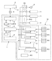
本実施形態に係る発電システム10は、発電装置(一例として太陽電池PV)と、太陽
電池PVで発電された直流電力を交流電力に変換し電力系統8へ供給する電力変換システ
ム1とを備える。電力変換システム1は、電力変換装置2、制御装置5等を含む。
The
発電システム10は、少なくとも一つの太陽電池PVを含む。太陽電池PVは、電力変
換装置2と接続される。ただし、太陽電池PVの個数はこれに限られない。例えば、図1
に示されるように、発電システム10は、複数の太陽電池PVを含んでいてもよい。複数
の太陽電池PVが含まれる場合に関しても同様に、各々の太陽電池PVは、少なくとも一
つの電力変換装置2に接続される。図1において、発電システム10は、符号2a、2b
、2c、・・・2nで示されるn個の電力変換装置2を含んでいるが、電力変換装置2の
個数はこれに限られない。
The
As shown in, the
2, 2c, ... 2n includes n
前述のように、電力変換装置2は、太陽電池PVから送出される直流電力を交流電力に
変換し、変換された交流電力を電力系統8や電力系統8に接続される負荷11等へ供給す
る。電力変換装置2において、直流電力を交流電力へ変換する機能は、DC/ACインバ
ータ回路によって担われる。また、電力変換装置2は、太陽電池PVから出力される直流
電力の電圧を所定値まで昇圧するDC/DCコンバータ回路(昇圧回路)を備えているこ
とが好ましい。DC/DCコンバータ回路によって昇圧された直流電力が、DC/ACイ
ンバータ回路に供給される。更に、電力変換装置2は、太陽電池PVで発電された電力を
蓄電する蓄電装置とも接続されていてもよい。
As described above, the
各電力変換装置2は、DC/ACインバータ回路、DC/DCコンバータ回路の他に、
演算部、通信部等を備えることが好ましい。後述するように、電力変換装置2は、制御装
置5からの出力抑制に係る制御信号(第1信号)等に基づき、出力電力を抑制する。電力
変換装置2は、通信部を介して制御装置5へ第1信号を受信する。また、電力変換装置2
は、受信した第1信号を演算部で処理し、出力する電力を抑制する。
Each
It is preferable to include a calculation unit, a communication unit, and the like. As will be described later, the
Processes the received first signal in the arithmetic unit and suppresses the output power.
また、電力変換装置2は、接続される太陽電池PVにおける発電電力値情報や、日の入
りなどの関係で太陽電池PVからの発電電力値が所定値以下となった際、その旨を伝達す
るための情報(第2信号)を制御装置5へ送信する機能を備えることが好ましい。これに
より、太陽電池PVからの発電が得られない状態にあることを速やかに制御装置5へ伝え
ることができ、制御装置5及びこれを含むシステム(電力変換システム1、発電システム
10)の省電力化を図ることができる。これらの機能に関しても、前述の演算部や通信部
を用いて実現される。
Further, the
更に、電力変換装置2は、第2信号の生成機能及び送信機能に加えて、例えば、日の出
等によって太陽電池PVからの発電電力が所定値を超えた場合に、その旨を制御装置5へ
伝達するための第3信号を生成し、これを制御装置5へ送信する機能を備えていてもよい
。これにより、太陽電池PVが十分な発電機能を回復してすぐに電力変換装置2から電力
を出力可能な状態に戻すことができる。その結果、既に十分な日射量があるにも関わらず
第1信号の再開が遅れるなどの事態を防ぐことができ、発電電力をロスを抑制し効率的に
出力することができる。
Further, in addition to the second signal generation function and transmission function, the
次に、図2を用いて、本実施形態に係る電力変換装置2に含まれる回路構成について説
明する。図2は、本実施形態に係る電力変換装置2の配線システム概略図である。具体的
には、太陽電池PV(発電装置)が1系統である場合の単相二線式の電力変換回路の概略
図である。ただし、他の太陽電池PVの第2系統、第3系統、第4系統・・・第n系統と
いうように複数設けられる場合は、太陽電池PVからインバータ回路DAまで上記第1系
統と同様の構成であり、インバータ回路DA以降の回路が共通となるように、第2系統、
第3系統、第4系統・・・第n系統とが並列接続される。
Next, the circuit configuration included in the
The third system, the fourth system, and the nth system are connected in parallel.
太陽電池PVで発電した直流電力は、昇圧回路BSに供給される。昇圧回路BSは、直
流用リアクトルL1、スイッチング素子S1、ダイオードD1、コンデンサC1からなる
チョッパ回路により構成され、スイッチング素子S1を所定の周波数でON/OFFする
ことにより、入力された直流電力の電圧を所定の電圧に昇圧する。昇圧回路BSで昇圧し
た直流電力は、インバータ回路DAへ出力される。
The DC power generated by the solar cell PV is supplied to the booster circuit BS. The booster circuit BS is composed of a chopper circuit including a DC reactor L1, a switching element S1, a diode D1, and a capacitor C1. By turning on / off the switching element S1 at a predetermined frequency, the input DC power voltage is applied. Boost to a predetermined voltage. The DC power boosted by the booster circuit BS is output to the inverter circuit DA.
インバータ回路DAは、複数のスイッチング素子S2〜S5をフルブリッジ接続した回
路である。これらのスイッチング素子S2〜S5は、PWM制御により周期的にON/O
FFされる。これにより、電力系統8の周波数に同期する疑似正弦波の交流電力に変換さ
れる。この変換された交流電力は、交流リアクトルL2及びコンデンサC2からなるロー
パスフィルタ回路LFにて高周波成分を減衰させて正弦波状に成形される。高周波成分が
減衰された交流電力は、リレー接点RYを介して電力系統8へ重畳される。
The inverter circuit DA is a circuit in which a plurality of switching elements S2 to S5 are fully bridged. These switching elements S2 to S5 are periodically turned on / O by PWM control.
It is FF. As a result, it is converted into pseudo sine wave AC power synchronized with the frequency of the
制御回路PCは、マイコン等からなり、昇圧回路BSのスイッチング素子S1やインバ
ータ回路DAのスイッチング素子S2〜S5のON/OFF動作の制御等を行う。また、
太陽電池PVの直流供給切替のためのスイッチング回路等を適宜備える。
The control circuit PC is composed of a microcomputer or the like, and controls the ON / OFF operation of the switching element S1 of the booster circuit BS and the switching elements S2 to S5 of the inverter circuit DA. also,
A switching circuit or the like for switching the DC supply of the solar cell PV is appropriately provided.
また、電力変換装置2は、制御装置5に接続される。図1に示されるように、電力変換
装置2が複数設けられる場合、制御装置5と個々の電力変換装置2とが接続されてもよい
。複数の電力変換装置2と制御装置5との接続形態は、制御装置5に対して、個々の電力
変換装置2が直列的(シリアル状)に接続されてもよいし、並列的に接続されてもよい。
ただし、制御装置5から送信される信号が、隣り合う電力変換装置2間で順次受け渡され
るシリアル接続であることが好ましい。シリアル接続の場合、制御装置5は、一の電力変
換装置2に信号を一度送信するのみで、全ての電力変換装置2に当該情報を伝達できる。
シリアル接続の例として、制御装置5に直接接続される一の電力変換装置2aに、他の電
力変換装置2b、2cが、直列的に順次接続される形態が挙げられる。
Further, the
However, it is preferable that the signals transmitted from the
As an example of the serial connection, there is a mode in which the other power conversion devices 2b and 2c are sequentially connected in series to one power conversion device 2a directly connected to the
また、制御装置5は、前述のように電力管理サーバ3に接続される。ここで、電力管理
サーバ3は、発電システム10が接続される電力系統8を所管する電力会社によって管理
されるサーバである。より詳しくは、電力管理サーバ3は、電力系統8に接続される各発
電システムからの出力電力を調整(抑制)するためのスケジュール情報7を作成し、これ
を制御装置5に送信する。或いは、制御装置5からスケジュール情報7取得のためのアク
セスがあった場合に電力管理サーバ3が応答し、スケジュール情報7を制御装置5に送信
しても良い。
Further, the
制御装置5は、これに接続される全ての電力変換装置の出力電力を抑制するよう制御す
る。より詳しくは、電力管理サーバ3から送信されたスケジュール情報7に基づき、制御
装置5は、出力電力を抑制するための抑制情報に基づく第1信号を各電力変換装置2に送
信する。
The
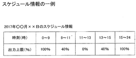
図3を参照して、電力管理サーバ3から送信されるスケジュール情報7の一例を説明す
る。スケジュール情報7は、例えば、各発電システム10における出力電力の上限値と、
当該上限値を実施する時間帯(時刻)を含む。出力電力の上限値の単位は、各発電システ
ム10から出力可能な最大出力電力の百分率である。
An example of the schedule information 7 transmitted from the power management server 3 will be described with reference to FIG. The schedule information 7 includes, for example, an upper limit value of the output power in each
Includes the time zone (time) when the upper limit is implemented. The unit of the upper limit value of the output power is a percentage of the maximum output power that can be output from each
本実施形態におけるスケジュール情報7は、電力管理サーバ3から、個々の発電システ
ム10に対して送信される。尚、個々の発電システム10の有する電力変換装置毎のスケ
ジュールとしても良い。ただし、スケジュール情報7の送信方法は、これに限られない。
図3に示される例は、一日の電力抑制スケジュールを示すものであるが、スケジュール情
報7は、複数日のスケジュールを含むものであってもよい。例えば、スケジュール情報7
は、発電システム毎に生成される一か月分の抑制スケジュールを含むなどが考えられる。
The schedule information 7 in this embodiment is transmitted from the power management server 3 to each
The example shown in FIG. 3 shows a daily power suppression schedule, but the schedule information 7 may include a schedule for a plurality of days. For example, schedule information 7
May include a one-month suppression schedule generated for each power generation system.
図3に示されるように、電力管理サーバ3から送信されるスケジュール情報7は、夜間
時の出力制御情報を含むものが通常である。すなわち、何らの制限を設けらない場合、ス
ケジュール情報7を受信した制御装置5は、太陽電池PVからの発電の得られない夜間時
も電力変換装置2に対して第1信号を送信することとなる。この場合、実質的に電力変換
装置2から電力系統8等へ発電電力が供給されないにも関わらず、制御装置5は常に電力
変換装置2へ第1信号を送信し続ける。このような事態を避けるため、制御装置5は、太
陽電池PVからの発電電力が所定値以下となった場合に、第1信号の送信を停止する手段
を備える(詳細は、後述する。)。
As shown in FIG. 3, the schedule information 7 transmitted from the power management server 3 usually includes output control information at night. That is, if no restriction is set, the
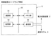
次に、制御装置5のハードウェア構成に関して図4を参照して説明する。図4に示され
るように、制御装置5は、演算部51、メモリ部52、記憶部53、通信部54を含む。
また、これらのハードウェアは、内部バス55によって相互に接続される。制御装置5は
、通信部54を介して、電力変換装置2や電力管理サーバ3と通信を行なう。
Next, the hardware configuration of the
Also, these hardware are interconnected by an
演算部51は、例えば、Central Processing Unit(以下、「
CPU」)であり、メモリ部52は、例えば、Random Access Memor
y(以下、「RAM」)であり、記憶部53は、例えば、Read Only Memo
ry(以下、「ROM」)やハードディスクドライブ等である。ここで、メモリ部52は
、演算部51のワークエリアとして機能し、記憶部53は、各種情報処理を行うためのプ
ログラムやデータを格納する。
The
CPU ”), and the
y (hereinafter, “RAM”), and the
It is a ry (hereinafter, “ROM”), a hard disk drive, or the like. Here, the
上記ハードウェア及びそれにインストールされるソフトウェアによって、制御装置5は
、例えば、以下の手段を備えるよう機能する。
(1)電力管理サーバ3、電力変換装置2、その他電気的に接続される各種装置との間で
情報(信号)の送受信を行なう手段(例えば、電力管理サーバ3から送信されたスケジュ
ール情報7の受信、電力変換装置2への第1信号の送信、電力変換装置2からの第2信号
の受信等に関する情報の送受信 等)。
(2)電力変換装置2からの第2信号の受信に伴い、電力変換装置2への第1信号の送信
を停止する手段。
もちろん、制御装置5に備わる手段は、上記に限られない。制御装置5は、他の手段を
備えていてもよい。
その他の手段としては、例えば下記が挙げられる。
(3)例えば、日の出等によって太陽電池PVからの発電電力が所定値を超えた場合に電
力変換装置2から送信される第3信号を受信すると、電力変換装置2への第1信号の送信
を再開する手段。
Depending on the hardware and the software installed therein, the
(1) Means for transmitting / receiving information (signals) to / from the power management server 3, the
(2) A means for stopping the transmission of the first signal to the
Of course, the means provided in the
Other means include, for example, the following.
(3) For example, when the third signal transmitted from the
なお、第2信号、第3信号の生成・送信に関する発電電力の閾値は、任意に設定可能で
ある。一例として、太陽電池PV(電力変換装置2)の最大出力値の1〜10%となった
段階で第2信号、第3信号を生成し送信するなどが考えられる。また、予め予想される当
日の天気情報等に基づいて、当該閾値を適宜変更してもよい。更に、これらを組み合せて
、制御装置5及び電力変換装置2の少なくとも一方が閾値を算出してもよい(例えば、晴
天が予想される日は、太陽電池PV(電力変換装置2)の最大出力値の1〜10%を閾値
とするが、曇りや雨が予想される日は、上記の値よりも大きな値、例えば5〜15%を閾
値として設定する、などが考えられる。)。なお、上記閾値の設定は、常時同じ数値を用
いるものであってもよいし、適宜タイミングのみで変更するものであってもよい。
The threshold value of the generated power related to the generation / transmission of the second signal and the third signal can be arbitrarily set. As an example, it is conceivable to generate and transmit the second signal and the third signal when the maximum output value of the solar cell PV (power conversion device 2) becomes 1 to 10%. In addition, the threshold value may be appropriately changed based on the weather information of the day expected in advance. Further, by combining these, at least one of the
図1に示されるように、制御装置5は、通信モデム6を介して電力管理サーバ3と接続
されてもよい。また、制御装置5は、モニター装置9と接続されていてもよい。モニター
装置9は、制御装置5の動作状態等をモニターするためのものであり、ディスプレー等の
表示部と、キーボードやマウス等の入力部、通信部、入力部や通信部を介して入力された
各種情報に基づき演算を行なう演算部等を備えることが好ましい。更に、制御装置5(及
び/又は電力変換装置2)は、任意の日の天気を予想する天気予報サーバ等とも接続され
ていてもよい。また、制御装置5のや電力変換装置2の設定や動作の指示を行うリモコン
としても機能することができる。
As shown in FIG. 1, the
例えば、本実施形態に係る発電システム10が、住宅に設置される形態である場合、家
庭内の電気機器(家庭内負荷)11を遠隔操作することに用いるHEMS(Home E
nergy Management System)と称されるコントローラ12を備え
ていてもよい。本実施形態では、コントローラ12は、図1に示されるように通信モデム
6と接続されている。その他、発電システム10が、商業用ビルディングや工場等に設置
される場合、通信モデム6は、BEMS(Building Energy Manag
ement System)や、FEMS(Factory Energy Manag
ement System)を備えていてもよい。
For example, when the
A
element System) and FEMS (Factory Energy Management)
It may be provided with an element system).
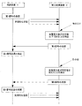
次に、図5を参照して、制御装置5及び電力変換装置2の動作の流れを説明する。図5
は、本実施形態に係る制御装置5と電力変換装置2との動作を示すシーケンス図である。
まず、制御装置5は、電力管理サーバ3より送信されたスケジュール情報7を受信し、当
該スケジュール情報7に基づき、出力電力の抑制制御信号(第1信号)を電力変換装置2
へ送信する。
Next, the operation flow of the
Is a sequence diagram showing the operation of the
First, the
Send to.
制御装置5は、第1信号の電力変換装置2に送信するに先立ち、電力変換装置2との通
信が可能な状態であるか否かを確認するため、電力変換装置2に対して確認用信号を送信
することが好ましい。確認用信号に対して電力変換装置2から応答信号があった場合、制
御装置5は、電力変換装置2との通信が可能であると判断する。それに伴い、制御装置5
は、電力変換装置2へ第1信号を送信する。なお、制御装置5は、所定間隔毎(例えば、
1分毎)に定期的に電力変換装置2へ第1信号を送信する。
Prior to transmitting the first signal to the
Transmits the first signal to the
The first signal is periodically transmitted to the
次に、例えば日の入りなどの状況が生じたことで、太陽電池PVでの発電電力量が所定
値(所定の閾値)以下となったことを電力変換装置2が検出した場合、電力変換装置2は
、その旨の情報を含む第2信号を生成する。最終的に、電力変換装置2は、生成した第2
信号を制御装置5へ送信する。
Next, when the
The signal is transmitted to the
第2信号を受信した制御装置5は、これまで電力変換装置2へ送信していた第1信号の
停止を行なう。これにより、以後、制御装置5から電力変換装置2へ第1信号が送信され
ない状態となるため、不必要な制御装置5の動作を防ぐことができる。
The
次に、例えば日の出などの状況が生じたことで、太陽電池PVでの発電電力量が所定値
を超えたことを電力変換装置2が検出した場合、電力変換装置2は、その旨の情報を含む
第3信号を生成する。最終的には、電力変換装置2は、生成した第3信号を制御装置5へ
送信する。
Next, when the
第3信号を受信した制御装置5は、停止していた第1信号の送信を再開する。以後、電
力変換装置2から次の第2信号を受信するまで、制御装置5は、電力変換装置2へ定期的
に第1信号を送信する。
The
以上、本発明の一実施形態について説明したが、以上の説明は本発明の理解を容易にす
るためのものであり、本発明を限定するものではない。本発明はその趣旨を逸脱すること
なく、変更、改良され得ると共に本発明にはその等価物が含まれることは勿論である。
Although one embodiment of the present invention has been described above, the above description is for facilitating the understanding of the present invention and does not limit the present invention. It goes without saying that the present invention can be modified and improved without departing from the spirit thereof, and the present invention includes its equivalents.
例えば、日の入りや日の出について直接太陽電池PVでの発電電力量が所定値(所定の
閾値)以下となった場合で判断していたが間接的に判断しても良い。具体的には、太陽電
池の発電電力が十分な際(日の出などで太陽電池PVでの発電電力量が所定値(所定の閾
値)以上となった場合)電力変換装置2は電力系統8に連系する際にはリレーRYを閉じ
て接続され、逆に太陽電池の発電電力が不足する際(日の入りなどで陽電池の発電電力が
所定の閾値以下である場合)は、リレーRYを開いて電力変換装置2と電力系統との間を
解列することを利用する。
For example, the amount of power generated by the solar cell PV is directly determined when the amount of power generated by the solar cell PV is equal to or less than a predetermined value (predetermined threshold value) for sunset or sunrise, but it may be determined indirectly. Specifically, when the power generated by the solar cell is sufficient (when the amount of power generated by the solar cell PV exceeds a predetermined value (predetermined threshold value) at sunrise or the like), the
即ち、リレーRYが閉じた状態から開いた状態になったことを検出してに、太陽電池の
発電電力が十分と判断し電力変換装置2は第2信号を制御装置5に送信しても良い。同様
に、リレーRYが開いた状態から閉じた状態になった場合に、電力変換装置2から制御装
置5へ第3信号を送信しても良い。
That is, after detecting that the relay RY has changed from the closed state to the open state, it is determined that the generated power of the solar cell is sufficient, and the
また、第2信号は、リレーが開いた後に制御装置5に送信することが望ましい。電力変
換装置2は、サーバからのスケジュールに基づく抑制動作を行う際には、スケジュール情
報が得られない場合やスケジュール情報に基づく制御信号(本実施形態では第1信号)が
得られない場合(即ち、通信途絶があった場合)安全のため(系統電圧上昇抑制のため)
に動作を停止するように設計される。リレーが開く前に第2信号を送信する場合、電力変
換装置2が動作を継続しようとしていても、通信途絶を検出して動作を停止してしまう可
能性があるため、リレーが開いてから第2信号を送信することでこのような事態を抑制す
ることができる。
Further, it is desirable that the second signal is transmitted to the
Designed to stop working. If the second signal is transmitted before the relay opens, even if the
また、第3信号も同様に、リレーが閉じる前に制御装置5に送信することが望ましい。
これにより、リレーが閉じる前、或いはリレーが閉じた直後(通信途絶が検出されるより
も前)までに、制御装置5が第1信号の送信を再開することができるので、電力変換装置
2が通信途絶を検出することなく動作を係属することができる。尚、リレーが閉じる前に
送信することが望ましいとしたが、上述のように電力変換装置2側で通信途絶が検出され
るよりも前に第1信号を送信できれば良いので、これに間に合うようであればリレーが閉
じた直後でも第3信号を送信しても良い。
Similarly, it is desirable that the third signal be transmitted to the
As a result, the
また、本実施形態では、電力変換装置2側で太陽電池PVの出力が太陽電池PVの発電
電力が十分得られるか否かを判定していたが、制御装置5側で判断しても良い。具体的に
は、制御装置5側で太陽電池PVの出力が可能な最大電力を予め設定しておき、電力変換
装置2から太陽電池PVの発電電力(出力電流の情報でも良い)を定期的に制御装置5へ
送信する。制御装置5は最大電力と発電電力を比較して、太陽電池PVの出力が太陽電池
PVの発電電力が十分得られるか否かを判定する。
Further, in the present embodiment, the
1・・・・・・・・電力変換システム
2・・・・・・・・電力変換装置(パワーコンディショナ)
3・・・・・・・・電力管理サーバ
5・・・・・・・・制御装置
6・・・・・・・・通信モデム
10・・・・・・・発電システム
PV・・・・・・・太陽電池
1 ・ ・ ・ ・ ・ ・ ・ ・
3 ・ ・ ・ ・ ・ ・ ・ ・
Claims (5)
置と前記電力変換装置の出力電力を抑制するスケジュール情報を送信するサーバと、通信
可能に接続され、
前記サーバから前記電力変換装置の出力電力を抑制するためのスケジュール情報を受信
し、前記スケジュール情報に基づき生成される前記電力変換装置の出力を制御するための
第1信号を前記電力変換装置に定期的に送信し、
前記太陽電池の発電電力が所定値以下の場合に、前記第1信号の送信を停止することを
特徴とする制御装置。 A power conversion device that converts the generated power of the solar cell into AC power and outputs the AC power to the power system and a server that transmits schedule information that suppresses the output power of the power conversion device are communicably connected.
The schedule information for suppressing the output power of the power conversion device is received from the server, and the first signal for controlling the output of the power conversion device generated based on the schedule information is periodically sent to the power conversion device. Send
A control device characterized in that transmission of the first signal is stopped when the generated power of the solar cell is equal to or less than a predetermined value.
ら受信し、
前記第2信号を受信すると前記第1信号の送信を停止することを特徴とする請求項1に
記載の制御装置。 A second signal transmitted when the generated power of the solar cell is equal to or less than a predetermined value is received from the power conversion device, and the power conversion device receives the second signal.
The control device according to claim 1, wherein when the second signal is received, the transmission of the first signal is stopped.
力変換装置から送信される第3信号を受信すると、前記第1信号の前記電力変換装置への
送信を再開することを特徴とする請求項2に記載の制御装置。 After stopping the transmission of the first signal, when the third signal transmitted from the power conversion device is received when the generated power of the solar cell exceeds a predetermined value, the first signal is sent to the power conversion device. The control device according to claim 2, wherein transmission is resumed.
置と、
サーバから前記電力変換装置の出力を抑制するためのスケジュール情報を受信し、スケ
ジュール情報に基づき生成される前記電力変換装置の出力を制御するための第1信号を前
記電力変換装置に定期的に送信する制御装置と、
を備え、
前記制御装置は、前記太陽電池の発電電力が所定値以下の場合に、前記第1信号の送信
を停止することを特徴とする電力変換システム。 A power conversion device that converts the power generated by a solar cell into AC power and outputs the AC power to the power system.
The schedule information for suppressing the output of the power conversion device is received from the server, and the first signal for controlling the output of the power conversion device generated based on the schedule information is periodically transmitted to the power conversion device. Control device and
With
The control device is a power conversion system characterized in that transmission of the first signal is stopped when the generated power of the solar cell is equal to or less than a predetermined value.
前記太陽電池の発電電力を交流電力に変換し当該交流電力を電力系統へ出力する電力変
換装置と、
サーバから前記電力変換装置の出力を抑制するためのスケジュール情報を受信し、前記
スケジュール情報に基づき生成され前記電力変換装置の出力を制御するための第1信号を
前記電力変換装置に定期的に送信する制御装置と、
を備え、
前記制御装置は、前記太陽電池の発電電力が所定値以下の場合に、前記第1信号の送信
を停止することを特徴とする発電システム。
With solar cells
A power conversion device that converts the generated power of the solar cell into AC power and outputs the AC power to the power system.
The schedule information for suppressing the output of the power conversion device is received from the server, and the first signal generated based on the schedule information for controlling the output of the power conversion device is periodically transmitted to the power conversion device. Control device and
With
The control device is a power generation system characterized in that transmission of the first signal is stopped when the generated power of the solar cell is equal to or less than a predetermined value.
Priority Applications (1)
| Application Number | Priority Date | Filing Date | Title |
|---|---|---|---|
| JP2017133402A JP6917543B2 (en) | 2017-07-07 | 2017-07-07 | Controls, power conversion systems, and power generation systems |
Applications Claiming Priority (1)
| Application Number | Priority Date | Filing Date | Title |
|---|---|---|---|
| JP2017133402A JP6917543B2 (en) | 2017-07-07 | 2017-07-07 | Controls, power conversion systems, and power generation systems |
Publications (2)
| Publication Number | Publication Date |
|---|---|
| JP2019017191A JP2019017191A (en) | 2019-01-31 |
| JP6917543B2 true JP6917543B2 (en) | 2021-08-11 |
Family
ID=65359171
Family Applications (1)
| Application Number | Title | Priority Date | Filing Date |
|---|---|---|---|
| JP2017133402A Active JP6917543B2 (en) | 2017-07-07 | 2017-07-07 | Controls, power conversion systems, and power generation systems |
Country Status (1)
| Country | Link |
|---|---|
| JP (1) | JP6917543B2 (en) |
Families Citing this family (1)
| Publication number | Priority date | Publication date | Assignee | Title |
|---|---|---|---|---|
| WO2025052813A1 (en) * | 2023-09-07 | 2025-03-13 | パナソニックIpマネジメント株式会社 | Control method, control device, and electric power generation system |
Family Cites Families (3)
| Publication number | Priority date | Publication date | Assignee | Title |
|---|---|---|---|---|
| US7890217B2 (en) * | 2009-10-26 | 2011-02-15 | General Electric Company | Integrated real-time power and solar farm control system |
| JP6677242B2 (en) * | 2015-03-13 | 2020-04-08 | 日本電気株式会社 | Power generation device monitoring and control system, power system, control device, management device, method and program |
| JP6429691B2 (en) * | 2015-03-18 | 2018-11-28 | 三菱電機株式会社 | Solar power generation system and power conditioner |
-
2017
- 2017-07-07 JP JP2017133402A patent/JP6917543B2/en active Active
Also Published As
| Publication number | Publication date |
|---|---|
| JP2019017191A (en) | 2019-01-31 |
Similar Documents
| Publication | Publication Date | Title |
|---|---|---|
| US20240313131A1 (en) | Distributed Maximum Power Point Tracking System, Structure and Process | |
| AU2014237119B2 (en) | Inverter communications using output signal | |
| JP5935268B2 (en) | Power generation control system | |
| US9660451B1 (en) | Islanded operation of distributed power sources | |
| US9444366B2 (en) | Dual mode micro-inverter system and operation | |
| EP3026776B1 (en) | Power conversion device, power management device, and power management method | |
| EP3026521B1 (en) | Power conversion device, power management method, and power management system | |
| US11128142B2 (en) | Photovoltaic power generation system and method for controlling the same | |
| JP6917543B2 (en) | Controls, power conversion systems, and power generation systems | |
| Fadel et al. | Iot-based power management for dc microgrids | |
| WO2015184869A1 (en) | Inverter control method and inverter | |
| CN117955426B (en) | Power equipment, power equipment control method and photovoltaic power generation system | |
| JP6617283B2 (en) | Power conversion system | |
| JP6656085B2 (en) | Power storage device, power conditioner and distributed power system | |
| JP6625469B2 (en) | Power control device | |
| JP7817309B2 (en) | Power conversion device, power conversion device control method, and solar power generation system | |
| JP2014112318A (en) | Control unit, power generation control unit, photovoltaic power generation system, control method and power generation control method | |
| JP2013230005A (en) | Control apparatus and power supply method | |
| JP2019017192A (en) | Controller, electric power conversion system and power generation system | |
| JP2012205322A (en) | Solar power generation system | |
| JP2006345679A (en) | Solar power system | |
| Müller et al. | Ripple control based control system for decentralised photovoltaic power plants | |
| JP2021010228A (en) | Control system, power conversion system, control method, and program |
Legal Events
| Date | Code | Title | Description |
|---|---|---|---|
| RD01 | Notification of change of attorney |
Free format text: JAPANESE INTERMEDIATE CODE: A7421 Effective date: 20190121 |
|
| A621 | Written request for application examination |
Free format text: JAPANESE INTERMEDIATE CODE: A621 Effective date: 20200616 |
|
| A977 | Report on retrieval |
Free format text: JAPANESE INTERMEDIATE CODE: A971007 Effective date: 20210427 |
|
| TRDD | Decision of grant or rejection written | ||
| A01 | Written decision to grant a patent or to grant a registration (utility model) |
Free format text: JAPANESE INTERMEDIATE CODE: A01 Effective date: 20210601 |
|
| A61 | First payment of annual fees (during grant procedure) |
Free format text: JAPANESE INTERMEDIATE CODE: A61 Effective date: 20210614 |
|
| R151 | Written notification of patent or utility model registration |
Ref document number: 6917543 Country of ref document: JP Free format text: JAPANESE INTERMEDIATE CODE: R151 |