JP6917454B2 - Improved synthesis of graphene oxide - Google Patents
Improved synthesis of graphene oxide Download PDFInfo
- Publication number
- JP6917454B2 JP6917454B2 JP2019526384A JP2019526384A JP6917454B2 JP 6917454 B2 JP6917454 B2 JP 6917454B2 JP 2019526384 A JP2019526384 A JP 2019526384A JP 2019526384 A JP2019526384 A JP 2019526384A JP 6917454 B2 JP6917454 B2 JP 6917454B2
- Authority
- JP
- Japan
- Prior art keywords
- graphene oxide
- graphite
- kmno
- mixture
- oxide slurry
- Prior art date
- Legal status (The legal status is an assumption and is not a legal conclusion. Google has not performed a legal analysis and makes no representation as to the accuracy of the status listed.)
- Active
Links
- OKTJSMMVPCPJKN-UHFFFAOYSA-N Carbon Chemical compound [C] OKTJSMMVPCPJKN-UHFFFAOYSA-N 0.000 title claims description 137
- 229910021389 graphene Inorganic materials 0.000 title claims description 94
- 230000015572 biosynthetic process Effects 0.000 title description 11
- 238000003786 synthesis reaction Methods 0.000 title description 6
- 238000000034 method Methods 0.000 claims description 64
- 229910002804 graphite Inorganic materials 0.000 claims description 36
- 239000010439 graphite Substances 0.000 claims description 36
- 239000002002 slurry Substances 0.000 claims description 20
- 239000000203 mixture Substances 0.000 claims description 17
- RTZKZFJDLAIYFH-UHFFFAOYSA-N Diethyl ether Chemical compound CCOCC RTZKZFJDLAIYFH-UHFFFAOYSA-N 0.000 claims description 8
- 238000006243 chemical reaction Methods 0.000 claims description 8
- 239000011541 reaction mixture Substances 0.000 claims description 8
- LFQSCWFLJHTTHZ-UHFFFAOYSA-N Ethanol Chemical compound CCO LFQSCWFLJHTTHZ-UHFFFAOYSA-N 0.000 claims description 6
- 230000008569 process Effects 0.000 claims description 6
- 239000006228 supernatant Substances 0.000 claims description 6
- 239000007864 aqueous solution Substances 0.000 claims description 4
- 239000000758 substrate Substances 0.000 claims description 4
- 238000004299 exfoliation Methods 0.000 claims description 3
- 230000002194 synthesizing effect Effects 0.000 claims description 3
- 239000003599 detergent Substances 0.000 claims 2
- 238000004140 cleaning Methods 0.000 claims 1
- 239000012459 cleaning agent Substances 0.000 claims 1
- QJGQUHMNIGDVPM-UHFFFAOYSA-N nitrogen group Chemical group [N] QJGQUHMNIGDVPM-UHFFFAOYSA-N 0.000 claims 1
- 230000003647 oxidation Effects 0.000 description 12
- 238000007254 oxidation reaction Methods 0.000 description 12
- 230000007547 defect Effects 0.000 description 11
- XLYOFNOQVPJJNP-UHFFFAOYSA-N water Chemical compound O XLYOFNOQVPJJNP-UHFFFAOYSA-N 0.000 description 10
- 239000010410 layer Substances 0.000 description 9
- 238000011020 pilot scale process Methods 0.000 description 8
- 239000000126 substance Substances 0.000 description 8
- 229910052799 carbon Inorganic materials 0.000 description 7
- 238000004611 spectroscopical analysis Methods 0.000 description 7
- 238000005481 NMR spectroscopy Methods 0.000 description 6
- 239000002356 single layer Substances 0.000 description 6
- 238000001228 spectrum Methods 0.000 description 6
- 238000006722 reduction reaction Methods 0.000 description 5
- 238000005033 Fourier transform infrared spectroscopy Methods 0.000 description 4
- 238000001069 Raman spectroscopy Methods 0.000 description 4
- 238000002441 X-ray diffraction Methods 0.000 description 4
- 238000000089 atomic force micrograph Methods 0.000 description 4
- 125000000524 functional group Chemical group 0.000 description 4
- VNWKTOKETHGBQD-UHFFFAOYSA-N methane Chemical compound C VNWKTOKETHGBQD-UHFFFAOYSA-N 0.000 description 4
- 230000009467 reduction Effects 0.000 description 4
- 238000003756 stirring Methods 0.000 description 4
- 238000002411 thermogravimetry Methods 0.000 description 4
- 239000002341 toxic gas Substances 0.000 description 4
- 230000009286 beneficial effect Effects 0.000 description 3
- 239000003153 chemical reaction reagent Substances 0.000 description 3
- 238000005229 chemical vapour deposition Methods 0.000 description 3
- 239000008367 deionised water Substances 0.000 description 3
- 229910021641 deionized water Inorganic materials 0.000 description 3
- 238000004519 manufacturing process Methods 0.000 description 3
- 239000010445 mica Substances 0.000 description 3
- 229910052618 mica group Inorganic materials 0.000 description 3
- 238000012986 modification Methods 0.000 description 3
- 230000004048 modification Effects 0.000 description 3
- 241000134253 Lanka Species 0.000 description 2
- GRYLNZFGIOXLOG-UHFFFAOYSA-N Nitric acid Chemical compound O[N+]([O-])=O GRYLNZFGIOXLOG-UHFFFAOYSA-N 0.000 description 2
- 238000001237 Raman spectrum Methods 0.000 description 2
- 238000003917 TEM image Methods 0.000 description 2
- 238000010521 absorption reaction Methods 0.000 description 2
- 238000004630 atomic force microscopy Methods 0.000 description 2
- 230000005540 biological transmission Effects 0.000 description 2
- 238000001460 carbon-13 nuclear magnetic resonance spectrum Methods 0.000 description 2
- 238000012512 characterization method Methods 0.000 description 2
- 150000002009 diols Chemical group 0.000 description 2
- 238000011156 evaluation Methods 0.000 description 2
- 239000000463 material Substances 0.000 description 2
- 239000007800 oxidant agent Substances 0.000 description 2
- 230000001590 oxidative effect Effects 0.000 description 2
- VKJKEPKFPUWCAS-UHFFFAOYSA-M potassium chlorate Chemical compound [K+].[O-]Cl(=O)=O VKJKEPKFPUWCAS-UHFFFAOYSA-M 0.000 description 2
- 239000007787 solid Substances 0.000 description 2
- 239000011343 solid material Substances 0.000 description 2
- 231100000331 toxic Toxicity 0.000 description 2
- 230000002588 toxic effect Effects 0.000 description 2
- 230000007704 transition Effects 0.000 description 2
- 238000001106 transmission high energy electron diffraction data Methods 0.000 description 2
- 238000002371 ultraviolet--visible spectrum Methods 0.000 description 2
- 230000004580 weight loss Effects 0.000 description 2
- BVKZGUZCCUSVTD-UHFFFAOYSA-M Bicarbonate Chemical compound OC([O-])=O BVKZGUZCCUSVTD-UHFFFAOYSA-M 0.000 description 1
- RYGMFSIKBFXOCR-UHFFFAOYSA-N Copper Chemical compound [Cu] RYGMFSIKBFXOCR-UHFFFAOYSA-N 0.000 description 1
- 239000004593 Epoxy Substances 0.000 description 1
- 238000001157 Fourier transform infrared spectrum Methods 0.000 description 1
- 238000005004 MAS NMR spectroscopy Methods 0.000 description 1
- 241000282320 Panthera leo Species 0.000 description 1
- 229910000831 Steel Inorganic materials 0.000 description 1
- 238000005411 Van der Waals force Methods 0.000 description 1
- 230000002378 acidificating effect Effects 0.000 description 1
- 238000004220 aggregation Methods 0.000 description 1
- 230000002776 aggregation Effects 0.000 description 1
- 150000001298 alcohols Chemical class 0.000 description 1
- 239000003125 aqueous solvent Substances 0.000 description 1
- 125000003118 aryl group Chemical group 0.000 description 1
- QVGXLLKOCUKJST-UHFFFAOYSA-N atomic oxygen Chemical group [O] QVGXLLKOCUKJST-UHFFFAOYSA-N 0.000 description 1
- 238000005102 attenuated total reflection Methods 0.000 description 1
- 239000006227 byproduct Substances 0.000 description 1
- 150000001721 carbon Chemical group 0.000 description 1
- 125000002915 carbonyl group Chemical group [*:2]C([*:1])=O 0.000 description 1
- 150000007942 carboxylates Chemical class 0.000 description 1
- 239000003638 chemical reducing agent Substances 0.000 description 1
- 238000000576 coating method Methods 0.000 description 1
- 239000002131 composite material Substances 0.000 description 1
- 230000008602 contraction Effects 0.000 description 1
- 229910052802 copper Inorganic materials 0.000 description 1
- 239000010949 copper Substances 0.000 description 1
- 239000013078 crystal Substances 0.000 description 1
- 238000011161 development Methods 0.000 description 1
- 125000005594 diketone group Chemical group 0.000 description 1
- 239000006185 dispersion Substances 0.000 description 1
- 238000004146 energy storage Methods 0.000 description 1
- 238000005516 engineering process Methods 0.000 description 1
- 150000002118 epoxides Chemical class 0.000 description 1
- 230000005284 excitation Effects 0.000 description 1
- 239000010408 film Substances 0.000 description 1
- 239000007789 gas Substances 0.000 description 1
- 239000007770 graphite material Substances 0.000 description 1
- 125000004356 hydroxy functional group Chemical group O* 0.000 description 1
- 239000012535 impurity Substances 0.000 description 1
- 230000000415 inactivating effect Effects 0.000 description 1
- 238000002329 infrared spectrum Methods 0.000 description 1
- 230000002687 intercalation Effects 0.000 description 1
- 238000009830 intercalation Methods 0.000 description 1
- 150000002500 ions Chemical class 0.000 description 1
- 230000001788 irregular Effects 0.000 description 1
- 150000002576 ketones Chemical class 0.000 description 1
- -1 manganate ester Chemical class 0.000 description 1
- 238000005259 measurement Methods 0.000 description 1
- 239000012528 membrane Substances 0.000 description 1
- QLTDWCHQCKHGGO-UHFFFAOYSA-N methane;sulfuric acid Chemical compound C.C.C.C.C.C.C.C.C.C.C.C.C.C.C.C.C.C.C.C.C.C.C.C.C.C.C.C.C.C.C.C.C.C.C.C.C.C.C.C.C.C.C.C.C.C.C.C.OS(O)(=O)=O.OS(O)(=O)=O.OS(O)(=O)=O.OS(O)(=O)=O.OS(O)(=O)=O.OS(O)(=O)=O.OS(O)(=O)=O QLTDWCHQCKHGGO-UHFFFAOYSA-N 0.000 description 1
- 229910021382 natural graphite Inorganic materials 0.000 description 1
- 238000000655 nuclear magnetic resonance spectrum Methods 0.000 description 1
- 229910052760 oxygen Inorganic materials 0.000 description 1
- 239000003973 paint Substances 0.000 description 1
- 230000000704 physical effect Effects 0.000 description 1
- 239000003495 polar organic solvent Substances 0.000 description 1
- 230000001681 protective effect Effects 0.000 description 1
- 238000010926 purge Methods 0.000 description 1
- 239000000376 reactant Substances 0.000 description 1
- 230000035484 reaction time Effects 0.000 description 1
- 238000012827 research and development Methods 0.000 description 1
- 230000029058 respiratory gaseous exchange Effects 0.000 description 1
- 230000035945 sensitivity Effects 0.000 description 1
- 230000003595 spectral effect Effects 0.000 description 1
- 239000010959 steel Substances 0.000 description 1
- QAOWNCQODCNURD-UHFFFAOYSA-N sulfuric acid Substances OS(O)(=O)=O QAOWNCQODCNURD-UHFFFAOYSA-N 0.000 description 1
- 239000010409 thin film Substances 0.000 description 1
- 210000003462 vein Anatomy 0.000 description 1
Images


Classifications
-
- C—CHEMISTRY; METALLURGY
- C01—INORGANIC CHEMISTRY
- C01B—NON-METALLIC ELEMENTS; COMPOUNDS THEREOF; METALLOIDS OR COMPOUNDS THEREOF NOT COVERED BY SUBCLASS C01C
- C01B32/00—Carbon; Compounds thereof
- C01B32/15—Nano-sized carbon materials
- C01B32/182—Graphene
- C01B32/198—Graphene oxide
-
- C—CHEMISTRY; METALLURGY
- C01—INORGANIC CHEMISTRY
- C01B—NON-METALLIC ELEMENTS; COMPOUNDS THEREOF; METALLOIDS OR COMPOUNDS THEREOF NOT COVERED BY SUBCLASS C01C
- C01B32/00—Carbon; Compounds thereof
- C01B32/20—Graphite
- C01B32/21—After-treatment
- C01B32/23—Oxidation
-
- C—CHEMISTRY; METALLURGY
- C01—INORGANIC CHEMISTRY
- C01B—NON-METALLIC ELEMENTS; COMPOUNDS THEREOF; METALLOIDS OR COMPOUNDS THEREOF NOT COVERED BY SUBCLASS C01C
- C01B32/00—Carbon; Compounds thereof
- C01B32/20—Graphite
- C01B32/21—After-treatment
- C01B32/22—Intercalation
- C01B32/225—Expansion; Exfoliation
Landscapes
- Chemical & Material Sciences (AREA)
- Organic Chemistry (AREA)
- Inorganic Chemistry (AREA)
- Life Sciences & Earth Sciences (AREA)
- General Life Sciences & Earth Sciences (AREA)
- Geology (AREA)
- Engineering & Computer Science (AREA)
- Materials Engineering (AREA)
- Nanotechnology (AREA)
- Carbon And Carbon Compounds (AREA)
Description
本発明は、酸化グラフェンの化学合成に関する。具体的には、先行技術の方法と比較して、本明細書に開示される発明は、有毒ガスの発生を防止し、H3PO4の使用を回避しながら、比較的大きくかつ高品質の酸化グラフェン材料を提供する、単純で費用効果が高い方法を提供する。 The present invention relates to the chemical synthesis of graphene oxide. Specifically, as compared to prior art methods, the invention disclosed herein is to prevent the generation of toxic gases, while avoiding the use of H 3 PO 4, a relatively large and high-quality Provide a simple and cost-effective way to provide graphene oxide material.
基本的に、グラフェンは、単層のグラファイト(すなわち、sp2混成炭素原子)からなる。グラフェンは、鋼鉄の約200倍の強度があり、毛髪のほぼ100万倍細く、銅より高い導電性を有する。このような独特かつ有益な物性により、グラフェン、特に高品質のグラフェンは、様々な業界での使用にとって望ましい。例えば、高品質のグラフェンを得ることは、電子およびフォトニック系用途で非常に重要である。現在、化学蒸着法が、これらの用途のための高品質のグラフェンを製造するのに好ましい経路である。しかし、化学蒸着は高価であり、現在、妥当な費用で大規模な工業用途で求められる量のグラフェンを製造することができない。 Basically, graphene consists of a single layer of graphite (ie, sp 2 hybrid carbon atom). Graphene is about 200 times stronger than steel, almost 1 million times thinner than hair, and more conductive than copper. Due to these unique and beneficial physical properties, graphene, especially high quality graphene, is desirable for use in various industries. For example, obtaining high quality graphene is very important in electronic and photonic applications. Currently, chemical vapor deposition is the preferred route for producing high quality graphene for these applications. However, chemical vapor deposition is expensive and it is currently not possible to produce the amount of graphene required for large-scale industrial applications at a reasonable cost.
その独特かつ有益な特性により、商業規模で高品質のグラフェンを費用効率よく製造するために、かなりの研究開発作業が現在行われている。大量のグラフェンを製造できると考えられるこのような方法の1つとしては、酸化グラフェンの化学的還元がある。酸化グラフェンの還元から形成されたグラフェンは、旧来、化学蒸着により製造されたグラフェンと比較して、製造過程で生じる欠陥(以下で考察する)に起因して低品質であった。酸化グラフェンの還元により製造されたグラフェンは、具体的には化学および生物学的検出装置、ならびにエネルギー貯蔵装置のための、ナノ複合体、機能性コーティング、塗料および電極材の分野における新しい技術的に進歩した材料の開発で現在用いられている。 Due to its unique and beneficial properties, considerable research and development work is currently underway to cost-effectively produce high quality graphene on a commercial scale. One such method that is believed to be capable of producing large amounts of graphene is the chemical reduction of graphene oxide. Graphene formed from the reduction of graphene oxide has traditionally been of lower quality than graphene produced by chemical vapor deposition due to defects (discussed below) that occur during the production process. Graphene produced by the reduction of graphene oxide is a new technology in the field of nanocomplexes, functional coatings, paints and electrodes, specifically for chemical and biological detectors and energy storage devices. Currently used in the development of advanced materials.
酸化グラフェンを形成する最も一般的な方法の1つとしては、ファンデルワールス力により一緒に保持される多数のグラフェンシートからなるグラファイト(例えば、バルクグラファイト)の化学的剥離法(chemical exfoliation)によるものがある。優れた高品質の純粋なバルクグラファイトの1つの源としては、スリランカ産塊状グラファイト(Sri Lankan vein graphite)がある。スリランカは、80〜99%炭素の範囲の純度レベルを有するその高品質の結晶塊状グラファイトで長年にわたり評価を得ている。スリランカ産塊状グラファイトは、塊(lumps)で採掘され、他の天然グラファイト材料と比較して、高度の結晶完全性、優れた電気および熱導電性、ならびにより高い凝集エネルギーを有すると考えられている。 One of the most common methods of forming graphene oxide is by chemical exfoliation of graphite (eg, bulk graphite) consisting of multiple graphene sheets held together by van der Waals forces. There is. One source of superior, high quality pure bulk graphite is Sri Lankan vein graphite. Sri Lanka has a long history of reputation for its high quality crystalline massive graphite with purity levels ranging from 80 to 99% carbon. Sri Lankan lump graphite is mined in lumps and is believed to have a high degree of crystal perfection, superior electrical and thermal conductivity, and higher aggregation energy compared to other natural graphite materials. ..
旧来の化学的剥離法では、グラファイトを強酸化剤で処理して、酸化グラフェンを製造する。最も早く記録された酸化グラフェンの合成の方法の1つは、Brodie(1859)によるものであった。Brodieは、塩素酸カリウムの一部を、発煙硝酸中のグラファイトのスラリーに添加することによる、酸化グラフェンの合成を示した。Staudenmaier(1898)によるその後の研究は、濃硫酸および発煙硝酸を使用し、塩素酸カリウムを複数のアリコートで反応期間にわたって添加することにより、Brodieの方法を改良した。Brodieの方法のStaudenmaierによる変更は、単一の反応容器における高度に酸化された酸化グラフェンの製造を、非常により現実的にする一助となった。Hummers(1958)は、この方法をさらに改良した(Hummersら、1958参照、本明細書において「Hummers」)。現在一般的に用いられているHummersの方法では、グラファイトを、濃H2SO4中でKMnO4およびNaNO3で処理することにより酸化する。 Traditional chemical stripping methods treat graphite with a strong oxidant to produce graphene oxide. One of the earliest recorded methods of graphene oxide synthesis was by Brodie (1859). Brodie showed the synthesis of graphene oxide by adding a portion of potassium chlorate to a slurry of graphite in fuming nitric acid. Subsequent studies by Studionier (1898) improved Brodie's method by using concentrated sulfuric acid and fuming nitric acid and adding potassium chlorate in multiple aliquots over the reaction period. The Staudenmaier modification of Brodie's method has helped make the production of highly oxidized graphene oxide in a single reaction vessel much more realistic. Hummers (1958) further refined this method (see Hummers et al., 1958, "Hummers" herein). The Hummers method commonly used today oxidizes graphite by treating it with KMnO 4 and NaNO 3 in concentrated H 2 SO 4.
酸化グラフェンを製造するこれらの旧来の方法には欠点がある。Brondie、StaudenmaierおよびHummersの方法各々を使用して、酸化グラフェンを形成することができるが、各々、商業規模での還元による高品質のグラフェンの形成に理想的とはいえない酸化グラフェン構造になる。より具体的には、これらの方法は各々、酸化グラフェンの化学構造に重大な欠陥をもたらし、欠陥は、その後の酸化グラフェンからグラフェンへの還元で容易に修復できない。例えば、Hummersの方法では、グラファイトのKMnO4での酸化によりマンガン酸エステルが形成され、これによりビシナルジオールが形成されるため、欠陥が生じ得る。保護されないままであった場合、ビシナルジオールは、ジケトンへと酸化される可能性があり、これにより、グラフェン基礎面に穴が形成される。得られた化学的に変換されたグラフェンにおけるこのような化学的欠陥は、高度に希求される電気的および機械的特性を、初期の状態の高品質のグラフェンと比較して減少させる。さらに、これらの先行技術の方法は各々、1種または複数の有毒ガス、例えば、NO2、N2O4および/またはClO2の発生を伴う。 These traditional methods of producing graphene oxide have drawbacks. Graphene oxide can be formed using each of the Brondie, Studionier and Hummers methods, but each results in a graphene oxide structure that is not ideal for the formation of high quality graphene by reduction on a commercial scale. More specifically, each of these methods results in significant defects in the chemical structure of graphene oxide, which cannot be easily repaired by subsequent reduction of graphene oxide to graphene. For example, in the Hummers method, oxidation of graphite with KMnO 4 forms a manganate ester, which forms a vicinal diol, which can lead to defects. If left unprotected, the vicinal diol can be oxidized to the diketone, which creates holes in the graphene basal plane. Such chemical defects in the resulting chemically transformed graphene reduce the highly sought-after electrical and mechanical properties compared to the high quality graphene in its initial state. In addition, each of these prior art methods involves the generation of one or more toxic gases, such as NO 2 , N 2 O 4 and / or ClO 2 .
近年、Hummersの方法の改良版が、Rice UniversityのJames Tourのグループにより開示された(米国特許出願公開第2012/0129736号を参照、本明細書において「Tour」)。この改良法は、NaNO3を排除し、大量のKMnO4およびH2SO4を必要とし、またH2SO4/H3PO4の9:1の混合物で反応を行う。Tourによれば、この方法では、有毒ガスが発生せず、得られた酸化グラフェンにおいて過剰な酸化および欠陥(すなわち、穴)の形成が防止される。また、Tourによれば、H3PO4の添加が、酸化グラフェン構造における過剰な酸化により生じ得る、欠陥の形成を防止する一助となる。ごく最近、Chenおよび協働者ら(Chenら、2013参照、本明細書において「Chen」)は、H3PO4を使用しない方法を発表したが、その酸化方法では、Tourのものよりも酸化が低い。 In recent years, an improved version of the Hummers method has been disclosed by the James Tour group at Rice University (see US Patent Application Publication No. 2012/01/29736, "Tour" herein). This modification eliminates NaNO 3 , requires large amounts of KMnO 4 and H 2 SO 4 , and reacts with a 9: 1 mixture of H 2 SO 4 / H 3 PO 4. According to Tour, this method does not generate toxic gas and prevents excessive oxidation and the formation of defects (ie, holes) in the resulting graphene oxide. Also, according to Tour, the addition of H 3 PO 4 helps prevent the formation of defects that can result from excessive oxidation in the graphene oxide structure. Most recently, Chen and his collaborators (see Chen et al., 2013, "Chen" herein) have announced a method that does not use H 3 PO 4 , but that oxidation method is more oxidative than that of Tour. low.
しかし、H3PO4の使用は、その費用および反応方法のより一層の複雑さにより望ましくない。さらに、KMnO4は、特に酸性媒体中で最も強い酸化剤の1つである。濃H2SO4でのグラファイトの完全なインターカレーションは、KMnO4の助けを借りて、重硫酸グラファイトを形成することにより実現され得る(Sorokinaら、2005参照)。したがって、重硫酸グラファイトの形成により、反応安定性が得られるので、NaNO3および/またはH3PO4の役割は、Hummersの方法による酸化グラフェン(本明細書では「GO」)の合成に不要である。したがって、有毒ガスまたは他の有毒な副産物を発生させずに、またはH3PO4を使用せずに、高品質で、高度に酸化された酸化グラフェン(すなわち、欠陥の少ない酸化グラフェン)をバルクグラファイトから形成する商業的に実現可能な方法を創製することは有益である。 However, the use of H 3 PO 4 is undesirable due to its cost and further complexity of the reaction method. Furthermore, KMnO 4 is one of the strongest oxidants, especially in acidic media. Complete intercalation of graphite at concentrated H 2 SO 4 can be achieved by forming graphite bisulfate with the help of KMnO 4 (see Sorokina et al., 2005). Therefore, the role of NaNO 3 and / or H 3 PO 4 is not required for the synthesis of graphene oxide (“GO” herein) by the Hummers method, as the formation of graphite bicarbonate provides reaction stability. be. Therefore, without generating toxic gases or other toxic by-products, or without the use of H 3 PO 4, a high-quality, highly oxidized graphene oxide (i.e., less graphene oxide defects) Bulk Graphite It is beneficial to create a commercially feasible method of forming from.
合成の試薬としてH2SO4、KMnO4、ならびにH2O2および/またはH2Oのみを使用してグラファイトから酸化グラフェンを化学合成する新規な方法が本明細書に開示される。本明細書に開示される方法は、先行技術の方法より拡張可能で、安価かつ安全である。本明細書に開示される方法により形成された化学的に剥離された酸化グラフェンは、水性と極性両方の有機溶媒中で高い溶解性を有し、薄膜にキャストされ得、先行技術の方法により形成された構造と比較して、比較的大きな横寸法を有する単層から数層の酸化グラフェン構造に剥離され得る。 A novel method for chemically synthesizing graphene oxide from graphite using only H 2 SO 4 , KMnO 4 , and H 2 O 2 and / or H 2 O as reagents for synthesis is disclosed herein. The methods disclosed herein are more extensible, cheaper and safer than the prior art methods. The chemically exfoliated graphene oxide formed by the methods disclosed herein has high solubility in both aqueous and polar organic solvents and can be cast into thin films, formed by prior art methods. It can be stripped from a single layer with a relatively large lateral dimension to a graphene oxide structure with several layers as compared to the structure.
より具体的には、本出願は、H2SO4、KMnO4のみを使用し、H2O2および/もしくはH2Oまたは氷で失活させて、グラファイトから酸化グラフェンを合成する、変更された化学酸化法を開示する。本発明の方法は、Tourに開示された方法で用いられる主要な保護試薬である、H3PO4を使用しない。驚くべきことにかつ意外にも、正確な割合でH2SO4、KMnO4、H2O2および/またはH2Oのみを試薬として使用して、H3PO4なしで、グラファイトから高品質の酸化グラフェンを形成できることが開示された。出願人らの発明前は、H3PO4の使用は、有毒ガスを伴わない方法でグラファイトから高品質の酸化グラフェンを形成するのに必須であると考えられていた。 More specifically, the present application has been modified to synthesize graphene oxide from graphite using only H 2 SO 4 , KMnO 4 and inactivating with H 2 O 2 and / or H 2 O or ice. Disclose the chemical oxidation method. The method of the present invention does not use H 3 PO 4 , which is the primary protective reagent used in the methods disclosed in Tour. Surprisingly and surprisingly, high quality from graphite, without H 3 PO 4 , using only H 2 SO 4 , KMnO 4 , H 2 O 2 and / or H 2 O as reagents in the correct proportions. It was disclosed that graphene oxide can be formed. Prior to the invention of the Applicants, the use of H 3 PO 4 was considered essential for the formation of high quality graphene oxide from graphite in a toxic gas-free manner.
一般に、本発明の実施形態において、グラファイトを、H2SO4が添加された容器に入れる。撹拌しながら、KMnO4をこのH2SO4/グラファイト混合物に添加する。次いで、撹拌を数時間続け、反応物を氷、H2O、ならびに/または氷およびH2O2で失活させる。次いで上清を廃棄し、酸化グラフェンスラリーを残す。次いで、残渣を、まず脱イオン水、続いて1:2の水:HCl混合物で数回洗浄して、Mn2+イオンおよび他の不純物を除去する。次いで、エタノールおよびジエチルエーテルで最後にもう一度洗浄して、酸化グラフェン粉末を得る。この工程後に得られた茶色の固体材料を、室温にて真空下で乾燥する。この実施形態において、反応の拡張性を判断するために、パイロット規模のプロセス(pilot scale process)も行う。 Generally, in embodiments of the present invention, graphite is placed in a container supplemented with H 2 SO 4. With stirring, KMnO 4 is added to this H 2 SO 4 / graphite mixture. Stirring is then continued for several hours to inactivate the reactants with ice, H 2 O, and / or ice and H 2 O 2. The supernatant is then discarded leaving the graphene oxide slurry. The residue is then washed several times with first deionized water followed by a 1: 2 water: HCl mixture to remove Mn 2+ ions and other impurities. The graphene oxide powder is then washed again with ethanol and diethyl ether. The brown solid material obtained after this step is dried at room temperature under vacuum. In this embodiment, a pilot scale process is also performed to determine the extensibility of the reaction.
あるいは、酸化グラフェンスラリーの一部を水溶液に滴下して添加し、次いで、水溶液/酸化グラフェンスラリーを超音波処理することにより、酸化グラフェンスラリーを剥離させてもよい。所望される場合、超音波処理した混合物を適当な基材に移してもよい。酸化グラフェンを水溶液中に分散させると、酸化グラフェンの単分子または実質的に単分子シートが生成される。次いで、これらのシートを還元して、還元型酸化グラフェンを得ることができ、グラフェンが形成される。 Alternatively, a part of the graphene oxide slurry may be added dropwise to the aqueous solution, and then the aqueous solution / graphene oxide slurry may be sonicated to exfoliate the graphene oxide slurry. If desired, the sonicated mixture may be transferred to a suitable substrate. Dispersion of graphene oxide in an aqueous solution produces a monomolecular or substantially monomolecular sheet of graphene oxide. These sheets can then be reduced to give reduced graphene oxide, which forms graphene.
以下の説明は、本明細書に開示される本発明の様々な実施の詳細な実施形態を提供するものである。この説明を読めば、様々な代替的な実施形態および代替的な応用で本発明を実施する方法が、当業者に明らかになるであろう。しかしながら、本発明の様々な実施形態が本明細書に記載されるが、これらの実施形態は、例示としてのみ示され、本発明を限定するものではないと理解されるものである。すなわち、様々な代替的な実施形態の詳細な説明は、本発明の範囲または広さを限定するように解釈されるべきではない。 The following description provides detailed embodiments of various embodiments of the invention disclosed herein. Reading this description will reveal to those skilled in the art how to implement the invention in various alternative embodiments and applications. However, although various embodiments of the invention are described herein, it is understood that these embodiments are shown by way of example only and are not intended to limit the invention. That is, the detailed description of the various alternative embodiments should not be construed to limit the scope or breadth of the invention.
一実施形態において、Bogala Graphite(GK)(スリランカ)から得た天然の高純度(>99%)塊状グラファイト約1.5gを、0℃のH2SO4(95〜97%、Sigma−Aldrich、分析等級)100mlに添加した。この添加中、混合物を0〜10℃で維持し、撹拌した。混合物を撹拌しながら、KMnO4約5.4g(99%、Lions Lab Chemicals、インド、LR等級)を適切な割合(すなわち、2g分−1)で添加した。混合物の温度を約0〜10℃で維持した。この時点で、反応混合物は緑色であった。KMnO4を添加した後、混合物を0〜10℃で12時間撹拌すると、混合物の色は暗褐色に変化した。12時間撹拌した後、反応混合物を氷約200gとH2O200mlとH2O21.5mlとの混合物で失活させた。この工程で、反応混合物の色は黄色に変化した。
In one embodiment, about 1.5 g of natural high-purity (> 99%) massive graphite obtained from Bogala Graphite (GK) (Sri Lanka) was added to H 2 SO 4 (95-97%, Sigma-Aldrich) at 0 ° C. Analytical grade) Added to 100 ml. During this addition, the mixture was maintained at 0-10 ° C and stirred. Approximately 5.4 g (99%, Lions Lab Chemicals, India, LR grade) of KMnO 4 was added in appropriate proportions (ie, 2 g -1 ) with stirring of the mixture. The temperature of the mixture was maintained at about 0-10 ° C. At this point, the reaction mixture was green. After adding KMnO 4 , the mixture was stirred at 0-10 ° C. for 12 hours and the color of the mixture changed to dark brown. After stirring for 12 hours, to deactivate the reaction mixture with a mixture of
次いで、上清を慎重に廃棄し、酸化グラフェンスラリーを残した。次に、残りの酸化グラフェンスラリーを脱イオン水400mlで洗浄し、次いで1:2HCl水溶液で洗浄した。その後、残りのスラリーをエタノール400mlおよびエーテル400mlで洗浄して、酸化グラフェン粉末を得た。得られた茶色の固体材料を室温にて真空下で乾燥した。 The supernatant was then carefully discarded leaving a graphene oxide slurry. The remaining graphene oxide slurry was then washed with 400 ml of deionized water and then with 1: 2 aqueous HCl. Then, the remaining slurry was washed with 400 ml of ethanol and 400 ml of ether to obtain graphene oxide powder. The resulting brown solid material was dried under vacuum at room temperature.
反応の拡張可能性を判断するために、パイロット規模プロセスで天然の高純度(>99%)塊状グラファイト約100gを使用することにより、パイロット規模プロセスも行う。一実施形態において、反応時間は20時間まで増加する。 A pilot-scale process is also performed by using approximately 100 g of natural high-purity (> 99%) massive graphite in the pilot-scale process to determine the expandability of the reaction. In one embodiment, the reaction time is increased to 20 hours.
あるいは、粘性の酸化グラフェンスラリー約5mgを脱イオン水約200mlに滴下して添加することにより、酸化グラフェンスラリーをさらに剥離させた。次いで、これらのスラリー/水混合物を超音波装置(Grant、USA、120W、150Hz)に20分間入れた。次いで、超音波処理した酸化グラフェンスラリー/水混合物を、新たに切断したマイカシート上に滴下して移し、原子間力顕微鏡画像を得た。 Alternatively, about 5 mg of viscous graphene oxide slurry was added dropwise to about 200 ml of deionized water to further exfoliate the graphene oxide slurry. These slurry / water mixtures were then placed in an ultrasonic device (Grant, USA, 120W, 150Hz) for 20 minutes. Then, the sonicated graphene oxide slurry / water mixture was dropped onto a newly cut mica sheet and transferred to obtain an atomic force microscope image.
酸化グラフェン膜特性評価
一実施形態において製造される酸化グラフェン膜上でのX線回折、熱重量分析、フーリエ変換赤外分光分析、核磁気共鳴分光分析、ラマン分光分析、原子間力顕微鏡および透過型電子顕微鏡測定によって、酸化プロセスにより生じた構造および化学変化が確認される。
Graphene Oxide Membrane characterization X-ray diffraction, thermogravimetric analysis, Fourier transform infrared spectroscopic analysis, nuclear magnetic resonance spectroscopic analysis, Raman spectroscopic analysis, atomic force microscopy and transmission type on the graphene oxide film produced in one embodiment. Electromicroscopy confirms the structural and chemical changes caused by the oxidation process.
1)X線回折特性評価
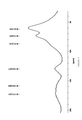
X線回折(「XRD」)データを、MBraun PSD位置感度検出器を備えたD8−Bruker AXS回折計で測定し、X軸を5°〜55°の(2θの)範囲内に制限した。図1(a)は、本発明の実施形態の方法に従って形成された酸化グラフェンから得られた代表的なXRDスペクトルを示している。図1(a)は、9.48±0.12Åの層間隔を示している。XRD層間隔は、酸化度に比例している。同様に、これは、還元すると単層グラフェンになり得る単層シートにGOを剥離させる容易さに関連している。ここで報告された層間隔は、Tourに開示された方法の使用を通じて報告された間隔と類似していることに注意されるべきである。しかし、図1(b)は、パイロット規模プロセスからの酸化グラフェンから得られたXRDスペクトルを例示しており、層間隔は9.59±0.12Åであり、非常に高い酸化度が確認される。この高い値は、これまで文献に報告されたことがない。
1) Evaluation of X-ray diffraction characteristics X-ray diffraction (“XRD”) data was measured with a D8-Brooker AXS diffractometer equipped with an MBran PSD position sensitivity detector, and the X-axis was 5 ° to 55 ° (of 2θ). Limited to the range. FIG. 1 (a) shows a representative XRD spectrum obtained from graphene oxide formed according to the method of the embodiment of the present invention. FIG. 1 (a) shows a layer spacing of 9.48 ± 0.12 Å. The XRD layer spacing is proportional to the degree of oxidation. Similarly, this is related to the ease with which GO can be exfoliated into a monolayer sheet that can be reduced to monolayer graphene. It should be noted that the layer spacing reported here is similar to the spacing reported through the use of the methods disclosed in Tour. However, FIG. 1 (b) illustrates the XRD spectrum obtained from graphene oxide from a pilot-scale process, with a layer spacing of 9.59 ± 0.12 Å, confirming a very high degree of oxidation. .. This high value has never been reported in the literature.
2)熱重量分析
熱重量分析(「TGA」)を、温度を補正した熱天秤(temperature compensated thermobalance)を備えたSDT Q600分析器で、高純度のN2パージ環境下で、ガス流量100ml/分で行った。試料を5℃/分の速度で35℃から1000℃に加熱した。図2は、本発明の実施形態の方法に従って形成された酸化グラフェンについて得られたTGAスペクトルを示している。図2のTGAスペクトルは、130℃〜220℃で顕著な重量減少を示す。これは、最も不安定な官能基からのCOおよびCO2の放出に対応している。220℃〜1000℃の緩やかな重量減少は、より安定な酸素官能基の除去に起因し得る。
2) Thermogravimetric Analysis Thermogravimetric analysis ( "TGA"), in SDT Q600 analyzer equipped with a heat balance with the corrected temperature (temperature compensated thermobalance), under N 2 purge environment high purity, gas flow rate 100ml / min I went there. The sample was heated from 35 ° C. to 1000 ° C. at a rate of 5 ° C./min. FIG. 2 shows the TGA spectra obtained for graphene oxide formed according to the method of the embodiment of the present invention. The TGA spectrum of FIG. 2 shows a significant weight loss from 130 ° C to 220 ° C. This corresponds to the release of CO and CO 2 from the most unstable functional groups. The gradual weight loss of 220 ° C. to 1000 ° C. may be due to the more stable removal of oxygen functional groups.
3)フーリエ変換赤外分光分析特性評価
利用可能な官能基の定性的判断を得るために、フーリエ変換赤外分光分析(「FTIR」)測定を、減衰全反射アクセサリーを備えたBruker NANCO Vertex 80 FTIR分光計に記録した。代表的なFTIRスペクトルを図3に示す。以下の官能基を特定した。ヒドロキシル伸縮バンド(3000〜4000cm−1)、1732cm−1のピークを、カルボニルC=O二重結合の伸縮振動として帰属し、1624cm−1の鋭く強い吸収を、インターカレートした水分子の伸縮モードとして帰属した。酸化されていないsp2CC結合からのC=C(1590〜1620cm−1)、1200cm−1以下のC−Oの振動およびC−O−C(−エポキシ−)の振動。観察されたスペクトルピーク位置は、Tourに開示された方法によるグラフェンに関して公表されたデータと非常によく一致している。
3) Fourier Transform Infrared Spectroscopy Characteristics Evaluation In order to obtain a qualitative judgment of the available functional groups, Fourier Transform Infraspectography (“FTIR”) measurement is performed by
4)ラマン分光分析
実験室およびパイロット規模プロセスでの試料のラマン分光分析を、514.5nm波長レーザーを使用するRenishaw InViaラマン分光計で行った。データを50倍対物で収集し、分光計を100cm−1〜3500cm−1で走査した。実験室およびパイロット規模プロセスでの2つの試料のラマンスペクトルを図4(a)および(b)各々に示す。通常、酸化グラフェンは、DおよびGと呼ばれる2つの突出したピークを有し、強度が低ければ低いほど、より高次のピーク2Dおよび3Sになる。Gピークは、ブリルアンゾーン中心でE2Gフォノンに対応し、グラファイトについては1580cm−1で観察される。実験室処理された試料のGピークは広く、1587cm−1にブルーシフトし、Tourに開示された方法に類似したより高次の酸化が確認される。その励起に欠陥を必要とし、sp2環のブリージングモードにより生じるDピークは、1352cm−1を中心とする。しかし、パイロット規模プロセスでの試料のGピーク位置は依然として1580cm−1であり、Dピークは、XRDですでに観察された極めて高い酸化により1347cm−1を中心とする。他の方法から得られたこれらのGOのI(D)/I(G)比は、実験室プロセスの0.95およびパイロット規模プロセスの0.94と比較して、通常約1以上である。低いI(D)/I(g)比は、現在の酸化法で生じるsp2結合したグラフェン構造中の欠陥の相対数が低いことを示している。不規則sp2炭素中の内部欠陥距離(La)は、I(D)/I(G)=C’(λ)La2、C’(514.5nm)約0.55nm−2の関係から計算できる。試料のLaの値は約1.3nmである。
4) Raman spectroscopic analysis Raman spectroscopic analysis of samples in the laboratory and pilot scale processes was performed on a Renishaw In Via Raman spectrometer using a 514.5 nm wavelength laser. Data were collected at 50-fold objective was scanned spectrometer at 100cm -1 ~3500cm -1. Raman spectra of the two samples in the laboratory and pilot scale processes are shown in FIGS. 4 (a) and 4 (b), respectively. Graphene oxide usually has two prominent peaks, called D and G, with lower intensities resulting in higher-order peaks 2D and 3S. The G peak corresponds to the E2G phonon at the center of the Brillouin zone and is observed at 1580 cm -1 for graphite. The G-peak of the laboratory-treated sample is wide, blue-shifted to 1587 cm-1 , confirming higher-order oxidation similar to the method disclosed in Tour. Require defects in its excitation, D peak caused by breathing mode of sp 2 ring is centered at 1352cm -1. However, the G peak position of the sample in the pilot scale process is still 1580 cm -1 , and the D peak is centered around 1347 cm -1 due to the extremely high oxidation already observed on XRD. The I (D) / I (G) ratio of these GOs obtained from other methods is typically greater than or equal to about 1 compared to 0.95 for the laboratory process and 0.94 for the pilot scale process. A low I (D) / I (g) ratio indicates a low relative number of defects in the sp 2-linked graphene structure produced by current oxidation methods. Irregular sp 2 internal defect distance in the carbon (La) is, I (D) / I ( G) = C '(λ)
5)固体13C核磁気共鳴(NMR)分光分析
図5は、高度に酸化された酸化グラフェンの固体直接13CパルスNMRスペクトルを示している。13C NMRスペクトルを50.3MHzにて、10kHzのマジック角回転、90°の13Cパルス、40msのFIDおよび20秒の弛緩遅延で得た。13C NMRスペクトルにおいて、6つのピークが62、73、87、130、159および約173ppmで観察され、各々、エポキシド、アルコール、ラクトール、グラファイトカーボン、カルボキシレートおよびケトンに帰属された。また、NMR結果は、酸化プロセスおよび報告された他の方法との良好な一致を十分に示している。
5) Solid 13 C Nuclear Magnetic Resonance (NMR) Spectroscopic Analysis Figure 5 shows a solid direct 13 C pulse NMR spectrum of highly oxidized graphene oxide. 13 C NMR spectra were obtained at 50.3 MHz with a magic angle spinning of 10 kHz, a 13 C pulse at 90 °, a FID of 40 ms and a relaxation delay of 20 seconds. In the 13 C NMR spectrum, six peaks were observed at 62, 73, 87, 130, 159 and about 173 ppm, which were assigned to epoxides, alcohols, lactols, graphite carbons, carboxylates and ketones, respectively. Also, the NMR results are in good agreement with the oxidation process and other reported methods.
6)原子間力顕微鏡画像
任意の酸化グラフェンの形成方法の商業上の利用可能性の最も重要な側面の1つは、適当な横寸法を有する単層から数層の酸化グラフェンシートを得ることができることである。上記のように、本発明の方法により形成された酸化グラフェンを剥離させて、原子間力顕微鏡による特性評価のためにマイカ基材上に移した。図6は原子間力顕微鏡画像(「AFM」)を示しており、高品質酸化グラフェンの単層から数層の比較的大きな(約5μ×7.5μ)シートの形成が確認される。このシートの横寸法は、HummersまたはTourの方法により得られた報告値よりもはるかに大きい。重要なことに、AFM画像により、本発明の方法により形成された酸化グラフェンシートが高品質であり、Tourの方法により形成された酸化グラフェンと類似しており、実質的に欠陥を含有しないことが確認される。
6) Atomic Force Microscopy One of the most important aspects of the commercial availability of any graphene oxide forming method is to obtain single to several layers of graphene oxide sheets with suitable lateral dimensions. You can do it. As described above, the graphene oxide formed by the method of the present invention was exfoliated and transferred onto a mica substrate for characterization by an atomic force microscope. FIG. 6 shows an atomic force microscope image (“AFM”), confirming the formation of relatively large (about 5 μ × 7.5 μ) sheets of high quality graphene oxide from a single layer to several layers. The lateral dimensions of this sheet are much larger than the reported values obtained by the Hummers or Tour method. Importantly, the AFM image shows that the graphene oxide sheet formed by the method of the present invention is of high quality, similar to the graphene oxide formed by Tour's method, and is substantially free of defects. It is confirmed.
7)透過型電子顕微鏡および制限視野電子回折(SAED)
図7(a)は、レース状炭素グリッド上に得られた単層/数層の高度に酸化された酸化グラフェンのTEM画像を示している。対応物は、図7(b)に示す酸化グラフェンの制限視野電子回折(SAED)パターンを示している。本開示の方法により調製した酸化グラフェンのSAEDパターンは、sp2結合した炭素平面における良好な結晶性およびより規則的な大きな炭素フレームワークを示している。
7) Transmission electron microscope and selected area diffraction (SAED)
FIG. 7 (a) shows a TEM image of a single layer / several layers of highly oxidized graphene oxide obtained on a lace-like carbon grid. The counterpart shows the selected area diffraction (SAED) pattern of graphene oxide shown in FIG. 7 (b). The SAED pattern of graphene oxide prepared by the methods of the present disclosure shows good crystallinity and a more regular large carbon framework in the sp 2-bonded carbon plane.
8)紫外線−可視光(UV−Vis)分光分析
図8は、濃度0.1mgml−1での酸化グラフェンのUV−Vis吸収スペクトルを示している。本開示のλmax値は231.6nmであり、アリール環のπ−π*遷移に起因する。これは、グラフェン層内に最大の無傷複合グラファイトドメインが存在することを意味する。さらに、約300nmでの小さなショルダーピークは、n−π*遷移の規格化された吸収によるものであり、sp2複合ドメインのC=O含有官能基の相対的な集団の増加を意味する。
8) Ultraviolet-Visible Light (UV-Vis) Spectroscopic Analysis FIG. 8 shows the UV-Vis absorption spectrum of graphene oxide at a concentration of 0.1 mgml-1. The λ max value of the present disclosure is 231.6 nm, which is due to the π-π * transition of the aryl ring. This means that the largest intact composite graphite domain is present in the graphene layer. Furthermore, a small shoulder peak at about 300nm is due to n-[pi * normalized absorption transitions, means an increase in relative population of C = O-containing functional groups of sp 2 complex domain.
開示された実施形態の上記説明は、当業者が本発明を製造または使用することを可能にするために提供される。これらの実施形態の様々な修正は、当業者には容易に明らかになり、本明細書に記載された一般原理は、本発明の精神または範囲から逸脱せずに他の実施形態に適用できる。したがって、本明細書に示された説明および図面が本発明の現時点での好ましい実施形態を示しており、したがって、本発明が広く企図する主題の代表であることを理解すべきである。本発明の範囲が、当業者に明らかになり得る他の実施形態を完全に包含しており、したがって、本発明の範囲は、添付の特許請求の範囲以外のなにものによっても限定されないことがさらに理解される。 The above description of the disclosed embodiments is provided to allow one of ordinary skill in the art to manufacture or use the present invention. Various modifications of these embodiments will be readily apparent to those skilled in the art and the general principles set forth herein can be applied to other embodiments without departing from the spirit or scope of the invention. Therefore, it should be understood that the description and drawings presented herein represent a current preferred embodiment of the invention and are therefore representative of the subject matter widely intended. The scope of the invention fully embraces other embodiments that may be apparent to those skilled in the art, and thus the scope of the invention may not be limited by anything other than the appended claims. Further understood.
Claims (13)
a.グラファイト源を得る工程と、
b.前記グラファイト源とH2SO4とを容器中で反応させる工程と、
c.KMnO4を前記容器に添加して、反応混合物を形成する工程であって、前記H2SO4、前記グラファイト源および前記KMnO4を、前記H2SO4の添加から前記KMnO4との反応まで、0℃〜10℃の温度で8時間以上最大約20時間維持する工程と、
d.H2O2およびH2Oを前記反応混合物に添加して、上清および酸化グラフェンスラリーを形成する工程と、
e.前記上清を分離して、前記酸化グラフェンスラリーを得る工程と
を含む前記方法。 A method of synthesizing graphene oxide with a layer spacing of 9.36 to 9.71 Å without the use of H 3 PO 4 or nitrogen-containing compounds.
a. The process of obtaining a graphite source and
b. The step of reacting the graphite source with H 2 SO 4 in a container, and
c. In the step of adding KMnO 4 to the container to form a reaction mixture, the H 2 SO 4 , the graphite source and the KMnO 4 are added to the H 2 SO 4 from the addition of the H 2 SO 4 to the reaction with the KMnO 4. , A process of maintaining at a temperature of 0 ° C to 10 ° C for 8 hours or more for a maximum of about 20 hours,
d. A step of adding H 2 O 2 and H 2 O to the reaction mixture to form a supernatant and a graphene oxide slurry.
e. The method comprising the step of separating the supernatant to obtain the graphene oxide slurry.
a.グラファイト源を得る工程と、
b.前記グラファイト源とH2SO4とを容器中で反応させる工程と、
c.KMnO4を前記容器に添加して、反応混合物を形成する工程であって、前記H2SO4、前記グラファイト源および前記KMnO4を、前記H2SO4の添加から前記KMnO4との反応まで、0℃〜10℃の温度で8時間以上、20時間まで維持する工程と、
d.H2O2およびH2Oを前記反応混合物に添加して、上清および酸化グラフェンスラリーを形成する工程と、
e.前記上清を分離して、前記酸化グラフェンスラリーを得る工程と
から本質的になる方法。 A method for synthesizing graphene oxide with a layer spacing of 9.36 to 9.71 Å.
a. The process of obtaining a graphite source and
b. The step of reacting the graphite source with H 2 SO 4 in a container, and
c. In the step of adding KMnO 4 to the container to form a reaction mixture, the H 2 SO 4 , the graphite source and the KMnO 4 are added to the H 2 SO 4 from the addition of the H 2 SO 4 to the reaction with the KMnO 4. , 0 ° C. to 10 ° C. temperature for 8 hours or more, the step of maintaining up to 20 hours,
d. A step of adding H 2 O 2 and H 2 O to the reaction mixture to form a supernatant and a graphene oxide slurry.
e. A method essentially consisting of the steps of separating the supernatant to obtain the graphene oxide slurry.
Applications Claiming Priority (3)
| Application Number | Priority Date | Filing Date | Title |
|---|---|---|---|
| US15/221,386 | 2016-07-27 | ||
| US15/221,386 US10336619B2 (en) | 2016-07-27 | 2016-07-27 | Method for the synthesis of graphene oxide |
| PCT/IB2017/054540 WO2018020439A1 (en) | 2016-07-27 | 2017-07-26 | An improved method for the synthesis of graphene oxide |
Publications (3)
| Publication Number | Publication Date |
|---|---|
| JP2019523210A JP2019523210A (en) | 2019-08-22 |
| JP2019523210A5 JP2019523210A5 (en) | 2021-05-27 |
| JP6917454B2 true JP6917454B2 (en) | 2021-08-11 |
Family
ID=61012180
Family Applications (1)
| Application Number | Title | Priority Date | Filing Date |
|---|---|---|---|
| JP2019526384A Active JP6917454B2 (en) | 2016-07-27 | 2017-07-26 | Improved synthesis of graphene oxide |
Country Status (6)
| Country | Link |
|---|---|
| US (1) | US10336619B2 (en) |
| JP (1) | JP6917454B2 (en) |
| KR (1) | KR102268849B1 (en) |
| AU (1) | AU2017304275B2 (en) |
| CA (1) | CA3031731C (en) |
| WO (1) | WO2018020439A1 (en) |
Families Citing this family (3)
| Publication number | Priority date | Publication date | Assignee | Title |
|---|---|---|---|---|
| CN108545724B (en) * | 2018-07-23 | 2020-06-09 | 山东玉皇新能源科技有限公司 | Graphene, production method and application thereof, and battery |
| CN113213464B (en) * | 2021-05-31 | 2022-04-29 | 杭州高烯科技有限公司 | Preparation method of spinning-grade single-layer graphene oxide slurry |
| KR102483223B1 (en) * | 2021-12-23 | 2023-01-02 | 주식회사 랩엠제로 | Method for manufacturing graphene oxide based on chemical exfoliation |
Family Cites Families (15)
| Publication number | Priority date | Publication date | Assignee | Title |
|---|---|---|---|---|
| US2798878A (en) | 1954-07-19 | 1957-07-09 | Nat Lead Co | Preparation of graphitic acid |
| CA2762430A1 (en) * | 2009-05-22 | 2011-02-10 | William Marsh Rice University | Highly oxidized graphene oxide and methods for production thereof |
| US20110262341A1 (en) * | 2010-04-25 | 2011-10-27 | Sri Lanka Institute of Nanotechnology (Pvt) Ltd. | Process for preparation of carbon nanotubes from vein graphite |
| GB201016925D0 (en) | 2010-10-07 | 2010-11-24 | Univ Manchester | Graphene oxide |
| KR102693192B1 (en) * | 2011-09-30 | 2024-08-09 | 가부시키가이샤 한도오따이 에네루기 켄큐쇼 | Anode, lithium secondary battery, electric vehicle, hybrid vehicle, moving bodies, system, and electrical devices |
| WO2014003252A1 (en) * | 2012-06-28 | 2014-01-03 | Idt International Co., Ltd. | Method and apparatus for manufacturing graphite oxide |
| JP2014034480A (en) * | 2012-08-07 | 2014-02-24 | Toshiba Corp | Production method of fine carbon, fine carbon produced by the production method, and composite material obtained by adding the fine carbon to base material |
| KR101472915B1 (en) * | 2012-10-09 | 2014-12-16 | 주식회사 그래핀올 | Method of producing graphene oxide |
| WO2014081389A1 (en) * | 2012-11-20 | 2014-05-30 | Nanyang Technological University | Method for forming a reduced graphene oxide/metal sulfide composite and its use as an anode for batteries |
| KR101500692B1 (en) * | 2013-04-11 | 2015-03-09 | 주식회사 아이디티인터내셔널 | Method and apparatus for manufacturing graphite oxide |
| US20160354729A1 (en) | 2013-04-12 | 2016-12-08 | General Electric Company | Membranes comprising graphene |
| US9637388B2 (en) * | 2013-05-24 | 2017-05-02 | Council Of Scientific & Industrial Research | Process for preparation of nanoporous graphene and graphene quantum dots |
| US9761894B2 (en) * | 2013-07-05 | 2017-09-12 | Daimler Ag | Porous inserts for improved coolant distribution in bipolar plate assemblies for fuel cells |
| US9452934B2 (en) * | 2013-09-12 | 2016-09-27 | The Hong Kong University Of Science And Technology | Synthesis of ultra-large graphene oxide sheets |
| CN105540869B (en) | 2015-12-17 | 2018-04-03 | 苏州大学 | A kind of modified graphene oxide composite for loading Paracoccus denitrificans and its production and use |
-
2016
- 2016-07-27 US US15/221,386 patent/US10336619B2/en active Active - Reinstated
-
2017
- 2017-07-26 AU AU2017304275A patent/AU2017304275B2/en not_active Ceased
- 2017-07-26 CA CA3031731A patent/CA3031731C/en not_active Expired - Fee Related
- 2017-07-26 KR KR1020197005673A patent/KR102268849B1/en not_active Application Discontinuation
- 2017-07-26 WO PCT/IB2017/054540 patent/WO2018020439A1/en active Application Filing
- 2017-07-26 JP JP2019526384A patent/JP6917454B2/en active Active
Also Published As
| Publication number | Publication date |
|---|---|
| CA3031731C (en) | 2021-06-08 |
| KR20190038585A (en) | 2019-04-08 |
| CA3031731A1 (en) | 2018-02-01 |
| JP2019523210A (en) | 2019-08-22 |
| AU2017304275B2 (en) | 2019-11-14 |
| US20180029887A1 (en) | 2018-02-01 |
| AU2017304275A1 (en) | 2019-03-14 |
| KR102268849B1 (en) | 2021-06-28 |
| WO2018020439A1 (en) | 2018-02-01 |
| US10336619B2 (en) | 2019-07-02 |
Similar Documents
| Publication | Publication Date | Title |
|---|---|---|
| Lavin-Lopez et al. | Influence of the reduction strategy in the synthesis of reduced graphene oxide | |
| He et al. | Mechanism of a green graphene oxide reduction with reusable potassium carbonate | |
| Díez et al. | Enhanced reduction of graphene oxide by high-pressure hydrothermal treatment | |
| Khan et al. | Pulicaria glutinosa plant extract: a green and eco-friendly reducing agent for the preparation of highly reduced graphene oxide | |
| Kumar et al. | Amino acid mediated functionalization and reduction of graphene oxide–synthesis and the formation mechanism of nitrogen-doped graphene | |
| Feng et al. | A green reduction of graphene oxide via starch-based materials | |
| Hanifah et al. | Synthesis of graphene oxide nanosheets via modified Hummers’ method and its physicochemical properties | |
| JP6917454B2 (en) | Improved synthesis of graphene oxide | |
| Mir et al. | Bilayer-rich graphene suspension from electrochemical exfoliation of graphite | |
| Liu et al. | Preparation and characterization of biobased graphene from Kraft lignin | |
| Liu et al. | Repeated microwave-assisted exfoliation of expandable graphite for the preparation of large scale and high quality multi-layer graphene | |
| Wang et al. | Thiourea dioxide as a green reductant for the mass production of solution-based graphene | |
| Wang et al. | Scalable exfoliation and dispersion of few-layer hexagonal boron nitride nanosheets in NMP-salt solutions | |
| KR20160031219A (en) | Method for preparing graphene-titanium dioxide nanocomposite | |
| Fronczak et al. | Facile and continuous synthesis of graphene nanoflakes in RF thermal plasma | |
| Biagiotti et al. | Nanostructured carbon materials decorated with organophosphorus moieties: synthesis and application | |
| Castelaín et al. | Comparative study of the covalent diazotization of graphene and carbon nanotubes using thermogravimetric and spectroscopic techniques | |
| Wang et al. | Alcohol addition improves the liquid-phase plasma process for “Green” reduction of graphene oxide | |
| Barman et al. | Hexamethylenetetramine mediated simultaneous nitrogen doping and reduction of graphene oxide for a metal-free SERS substrate | |
| Pełech et al. | Removal of metal particles from carbon nanotubes using conventional and microwave methods | |
| Kuanyshbekov et al. | Thermally Reduced Graphene Oxide Membranes From Local Kazakhstan Graphite “Ognevsky” | |
| Qureshi et al. | Expediting High‐Yield Mxene Carbides and Nitrides Synthesis for Next‐Generation 2D Materials | |
| Abou Zeid et al. | Radiation induced reduction of graphene oxide: a dose effect study | |
| JP2011051887A (en) | Method for preparing carbon nanotube, carbon nanotube film, and electronic device | |
| Chen et al. | Fabrication and photodegradation application of isopropanol-functionalized poly (triazine imide) |
Legal Events
| Date | Code | Title | Description |
|---|---|---|---|
| A521 | Request for written amendment filed |
Free format text: JAPANESE INTERMEDIATE CODE: A523 Effective date: 20190325 |
|
| A621 | Written request for application examination |
Free format text: JAPANESE INTERMEDIATE CODE: A621 Effective date: 20190325 |
|
| A977 | Report on retrieval |
Free format text: JAPANESE INTERMEDIATE CODE: A971007 Effective date: 20200220 |
|
| A131 | Notification of reasons for refusal |
Free format text: JAPANESE INTERMEDIATE CODE: A131 Effective date: 20200310 |
|
| A521 | Request for written amendment filed |
Free format text: JAPANESE INTERMEDIATE CODE: A523 Effective date: 20200610 |
|
| A131 | Notification of reasons for refusal |
Free format text: JAPANESE INTERMEDIATE CODE: A131 Effective date: 20201016 |
|
| A601 | Written request for extension of time |
Free format text: JAPANESE INTERMEDIATE CODE: A601 Effective date: 20210114 |
|
| A601 | Written request for extension of time |
Free format text: JAPANESE INTERMEDIATE CODE: A601 Effective date: 20210316 |
|
| A524 | Written submission of copy of amendment under article 19 pct |
Free format text: JAPANESE INTERMEDIATE CODE: A524 Effective date: 20210416 |
|
| TRDD | Decision of grant or rejection written | ||
| A01 | Written decision to grant a patent or to grant a registration (utility model) |
Free format text: JAPANESE INTERMEDIATE CODE: A01 Effective date: 20210625 |
|
| A61 | First payment of annual fees (during grant procedure) |
Free format text: JAPANESE INTERMEDIATE CODE: A61 Effective date: 20210719 |
|
| R150 | Certificate of patent or registration of utility model |
Ref document number: 6917454 Country of ref document: JP Free format text: JAPANESE INTERMEDIATE CODE: R150 |