JP6917349B2 - Gas sensor element - Google Patents
Gas sensor element Download PDFInfo
- Publication number
- JP6917349B2 JP6917349B2 JP2018156179A JP2018156179A JP6917349B2 JP 6917349 B2 JP6917349 B2 JP 6917349B2 JP 2018156179 A JP2018156179 A JP 2018156179A JP 2018156179 A JP2018156179 A JP 2018156179A JP 6917349 B2 JP6917349 B2 JP 6917349B2
- Authority
- JP
- Japan
- Prior art keywords
- insulator
- sensor element
- gas sensor
- gas
- boundary
- Prior art date
- Legal status (The legal status is an assumption and is not a legal conclusion. Google has not performed a legal analysis and makes no representation as to the accuracy of the status listed.)
- Active
Links
Images


Classifications
-
- G—PHYSICS
- G01—MEASURING; TESTING
- G01N—INVESTIGATING OR ANALYSING MATERIALS BY DETERMINING THEIR CHEMICAL OR PHYSICAL PROPERTIES
- G01N27/00—Investigating or analysing materials by the use of electric, electrochemical, or magnetic means
- G01N27/26—Investigating or analysing materials by the use of electric, electrochemical, or magnetic means by investigating electrochemical variables; by using electrolysis or electrophoresis
- G01N27/403—Cells and electrode assemblies
- G01N27/406—Cells and probes with solid electrolytes
- G01N27/4067—Means for heating or controlling the temperature of the solid electrolyte
-
- G—PHYSICS
- G01—MEASURING; TESTING
- G01N—INVESTIGATING OR ANALYSING MATERIALS BY DETERMINING THEIR CHEMICAL OR PHYSICAL PROPERTIES
- G01N27/00—Investigating or analysing materials by the use of electric, electrochemical, or magnetic means
- G01N27/26—Investigating or analysing materials by the use of electric, electrochemical, or magnetic means by investigating electrochemical variables; by using electrolysis or electrophoresis
- G01N27/403—Cells and electrode assemblies
- G01N27/406—Cells and probes with solid electrolytes
- G01N27/407—Cells and probes with solid electrolytes for investigating or analysing gases
- G01N27/4071—Cells and probes with solid electrolytes for investigating or analysing gases using sensor elements of laminated structure
-
- G—PHYSICS
- G01—MEASURING; TESTING
- G01N—INVESTIGATING OR ANALYSING MATERIALS BY DETERMINING THEIR CHEMICAL OR PHYSICAL PROPERTIES
- G01N27/00—Investigating or analysing materials by the use of electric, electrochemical, or magnetic means
- G01N27/26—Investigating or analysing materials by the use of electric, electrochemical, or magnetic means by investigating electrochemical variables; by using electrolysis or electrophoresis
- G01N27/403—Cells and electrode assemblies
- G01N27/406—Cells and probes with solid electrolytes
- G01N27/407—Cells and probes with solid electrolytes for investigating or analysing gases
- G01N27/409—Oxygen concentration cells
-
- H—ELECTRICITY
- H05—ELECTRIC TECHNIQUES NOT OTHERWISE PROVIDED FOR
- H05B—ELECTRIC HEATING; ELECTRIC LIGHT SOURCES NOT OTHERWISE PROVIDED FOR; CIRCUIT ARRANGEMENTS FOR ELECTRIC LIGHT SOURCES, IN GENERAL
- H05B3/00—Ohmic-resistance heating
- H05B3/02—Details
- H05B3/03—Electrodes
-
- H—ELECTRICITY
- H05—ELECTRIC TECHNIQUES NOT OTHERWISE PROVIDED FOR
- H05B—ELECTRIC HEATING; ELECTRIC LIGHT SOURCES NOT OTHERWISE PROVIDED FOR; CIRCUIT ARRANGEMENTS FOR ELECTRIC LIGHT SOURCES, IN GENERAL
- H05B3/00—Ohmic-resistance heating
- H05B3/10—Heater elements characterised by the composition or nature of the materials or by the arrangement of the conductor
- H05B3/18—Heater elements characterised by the composition or nature of the materials or by the arrangement of the conductor the conductor being embedded in an insulating material
-
- H—ELECTRICITY
- H05—ELECTRIC TECHNIQUES NOT OTHERWISE PROVIDED FOR
- H05B—ELECTRIC HEATING; ELECTRIC LIGHT SOURCES NOT OTHERWISE PROVIDED FOR; CIRCUIT ARRANGEMENTS FOR ELECTRIC LIGHT SOURCES, IN GENERAL
- H05B3/00—Ohmic-resistance heating
- H05B3/20—Heating elements having extended surface area substantially in a two-dimensional plane, e.g. plate-heater
- H05B3/22—Heating elements having extended surface area substantially in a two-dimensional plane, e.g. plate-heater non-flexible
- H05B3/28—Heating elements having extended surface area substantially in a two-dimensional plane, e.g. plate-heater non-flexible heating conductor embedded in insulating material
- H05B3/286—Heating elements having extended surface area substantially in a two-dimensional plane, e.g. plate-heater non-flexible heating conductor embedded in insulating material the insulating material being an organic material, e.g. plastic
Description
本発明は、ガスセンサ素子に関する。 The present invention relates to a gas sensor element.
特許文献1に開示されているように、ガスセンサは、例えば、内燃機関の排気管に配置され、排気管を流れる排ガスの酸素濃度等の特定ガス成分の濃度を検出するために用いられる。特許文献1に記載のガスセンサは、厚み方向に貫通形成された配置穴を備える保持板と、前記配置穴に配された固体電解質体とを有する電解質層を備える。 As disclosed in Patent Document 1, the gas sensor is arranged in the exhaust pipe of an internal combustion engine, for example, and is used to detect the concentration of a specific gas component such as the oxygen concentration of the exhaust gas flowing through the exhaust pipe. The gas sensor described in Patent Document 1 includes an electrolyte layer having an arrangement hole formed through the arrangement hole in the thickness direction and a solid electrolyte body arranged in the arrangement hole.
そして、特許文献1に記載のガスセンサは、配置穴と固体電解質体との境界部における前記保持板の厚み方向の両側に、一対の表面アルミナ層を配している。これにより、固体電解質体がアルミナシートから抜け出さないようにしようとしている。 The gas sensor described in Patent Document 1 has a pair of surface alumina layers arranged on both sides of the holding plate in the thickness direction at the boundary between the arrangement hole and the solid electrolyte. This is trying to prevent the solid electrolyte from coming out of the alumina sheet.
しかしながら、特許文献1に記載のガスセンサ素子においては、一対の表面アルミナ層の厚みが比較的薄く、一対の表面アルミナ層の強度が低い。それゆえ、固体電解質体を配置穴に安定して保持する観点から、改善の余地がある。 However, in the gas sensor element described in Patent Document 1, the thickness of the pair of surface alumina layers is relatively thin, and the strength of the pair of surface alumina layers is low. Therefore, there is room for improvement from the viewpoint of stably holding the solid electrolyte in the placement hole.
本発明は、かかる課題に鑑みてなされたものであり、固体電解質体が配置穴から抜け落ち難いガスセンサ素子を提供しようとするものである。 The present invention has been made in view of the above problems, and an object of the present invention is to provide a gas sensor element in which a solid electrolyte does not easily fall out of an arrangement hole.
本発明の一態様は、厚み方向(Z)に貫通形成された配置穴(220)を備える保持板(22)、及び前記配置穴に配されるとともに酸素イオン伝導性を有する固体電解質体(21)を備える電解質層(2)と、
前記電解質層の一方面に積層された第一絶縁体(3)と、
前記電解質層の他方面に積層された第二絶縁体(4)と、
前記電解質層と前記第一絶縁体とに囲まれるとともに被測定ガス(G)が導入される測定ガス室(5)と、
前記電解質層と前記第二絶縁体とに囲まれるとともに基準ガス(A)が導入される基準ガス室(6)と、
前記第一絶縁体に埋設されたヒータ(7)と、を有するガスセンサ素子(1)であって、
前記配置穴と前記固体電解質体との境界部(23)の少なくとも一部は、前記第一絶縁体の第一挟持部(33)と、前記第二絶縁体の第二挟持部(45)とによって挟持されており、
前記第一挟持部は、前記厚み方向において前記境界部と重なる位置に形成されているとともに、少なくとも、前記厚み方向における前記測定ガス室が配された全領域に形成されており、
前記第二挟持部は、前記厚み方向において前記境界部と重なる位置に形成されているとともに、少なくとも、前記厚み方向における前記基準ガス室が配された全領域に形成されており、
前記境界部は、前記ガスセンサ素子の幅方向(Y)に対向する一対の第一境界部(231)を有し、少なくとも一対の前記第一境界部の全体は、前記第一挟持部と前記第二挟持部とによって挟持されている、ガスセンサ素子にある。
本発明の他の態様は、厚み方向(Z)に貫通形成された配置穴(220)を備える保持板(22)、及び前記配置穴に配されるとともに酸素イオン伝導性を有する固体電解質体(21)を備える電解質層(2)と、
前記電解質層の一方面に積層された第一絶縁体(3)と、
前記電解質層の他方面に積層された第二絶縁体(4)と、
前記電解質層と前記第一絶縁体とに囲まれるとともに被測定ガス(G)が導入される測定ガス室(5)と、
前記電解質層と前記第二絶縁体とに囲まれるとともに基準ガス(A)が導入される基準ガス室(6)と、を有するガスセンサ素子(1)であって、
前記固体電解質体及び前記基準ガス室は、前記ガスセンサ素子の長手方向(X)の基端位置まで形成されており、
前記配置穴と前記固体電解質体との境界部(23)の少なくとも一部は、前記第一絶縁体の第一挟持部(33)と、前記第二絶縁体の第二挟持部(45)とによって挟持されており、
前記第一挟持部は、前記厚み方向において前記境界部と重なる位置に形成されているとともに、少なくとも、前記厚み方向における前記測定ガス室が配された全領域に形成されており、
前記第二挟持部は、前記厚み方向において前記境界部と重なる位置に形成されているとともに、少なくとも、前記厚み方向における前記基準ガス室が配された全領域に形成されており、
前記境界部は、前記ガスセンサ素子の幅方向(Y)に対向する一対の第一境界部(231)を有し、少なくとも一対の前記第一境界部の全体は、前記ガスセンサ素子の長手方向の基端位置まで前記第一挟持部と前記第二挟持部とによって挟持されている、ガスセンサ素子にある。
One aspect of the present invention is a holding plate (22) having an arrangement hole (220) formed through the thickness direction (Z), and a solid electrolyte body (21) arranged in the arrangement hole and having oxygen ion conductivity. ), And the electrolyte layer (2)
The first insulator (3) laminated on one surface of the electrolyte layer and
The second insulator (4) laminated on the other surface of the electrolyte layer and
A measurement gas chamber (5) surrounded by the electrolyte layer and the first insulator and into which the gas to be measured (G) is introduced.
A reference gas chamber (6) surrounded by the electrolyte layer and the second insulator and into which the reference gas (A) is introduced.
A heater (7) embedded in the first insulator, a gas sensor element to have a (1),
At least a part of the boundary portion (23) between the arrangement hole and the solid electrolyte body includes a first sandwiching portion (33) of the first insulator and a second sandwiching portion (45) of the second insulator. Is sandwiched by
The first sandwiching portion is formed at a position overlapping the boundary portion in the thickness direction, and is formed at least in the entire region where the measurement gas chamber is arranged in the thickness direction.
The second sandwiching portion is formed at a position overlapping the boundary portion in the thickness direction, and is formed at least in the entire region where the reference gas chamber is arranged in the thickness direction.
The boundary portion has a pair of first boundary portions (231) facing each other in the width direction (Y) of the gas sensor element, and at least the entire pair of the first boundary portions is the first holding portion and the first holding portion. It is sandwiched by the second clamping part, in the gas sensor element.
Another aspect of the present invention is a holding plate (22) having an arrangement hole (220) formed through the thickness direction (Z), and a solid electrolyte body arranged in the arrangement hole and having oxygen ion conductivity ( 21) and the electrolyte layer (2)
The first insulator (3) laminated on one surface of the electrolyte layer and
The second insulator (4) laminated on the other surface of the electrolyte layer and
A measurement gas chamber (5) surrounded by the electrolyte layer and the first insulator and into which the gas to be measured (G) is introduced.
A gas sensor element (1) surrounded by the electrolyte layer and the second insulator and having a reference gas chamber (6) into which the reference gas (A) is introduced.
The solid electrolyte body and the reference gas chamber are formed up to the base end position in the longitudinal direction (X) of the gas sensor element.
At least a part of the boundary portion (23) between the arrangement hole and the solid electrolyte body includes a first sandwiching portion (33) of the first insulator and a second sandwiching portion (45) of the second insulator. Is sandwiched by
The first sandwiching portion is formed at a position overlapping the boundary portion in the thickness direction, and is formed at least in the entire region where the measurement gas chamber is arranged in the thickness direction.
The second sandwiching portion is formed at a position overlapping the boundary portion in the thickness direction, and is formed at least in the entire region where the reference gas chamber is arranged in the thickness direction.
The boundary portion has a pair of first boundary portions (231) facing the width direction (Y) of the gas sensor element, and at least the entire pair of the first boundary portions is a base in the longitudinal direction of the gas sensor element. It is in the gas sensor element that is sandwiched by the first sandwiching portion and the second sandwiching portion up to the end position.
前記態様のガスセンサ素子において、保持板の配置穴と固体電解質体との境界部の少なくとも一部は、第一絶縁体の第一挟持部と第二絶縁体の第二挟持部とによって挟持されている。そして、第一挟持部は、少なくとも、保持板の厚み方向における測定ガス室が配された全領域に形成されている。また、第二挟持部は、少なくとも、前記厚み方向における基準ガス室が配された全領域に形成されている。すなわち、境界部の少なくとも一部は、比較的剛性の高い構造体で構成される第一挟持部及び第二挟持部により挟持されている。それゆえ、境界部の少なくとも一部を挟持する第一挟持部及び第二挟持部の剛性を確保しやすく、固体電解質体を配置穴に安定して保持しやすい。 In the gas sensor element of the above aspect, at least a part of the boundary portion between the arrangement hole of the holding plate and the solid electrolyte body is sandwiched between the first sandwiching portion of the first insulator and the second sandwiching portion of the second insulator. There is. The first holding portion is formed in at least the entire region where the measurement gas chamber in the thickness direction of the holding plate is arranged. Further, the second sandwiching portion is formed at least in the entire region where the reference gas chamber in the thickness direction is arranged. That is, at least a part of the boundary portion is sandwiched by the first sandwiching portion and the second sandwiching portion composed of a structure having relatively high rigidity. Therefore, it is easy to secure the rigidity of the first sandwiching portion and the second sandwiching portion that sandwich at least a part of the boundary portion, and it is easy to stably hold the solid electrolyte in the arrangement hole.
以上のごとく、前記態様によれば、固体電解質体が配置穴から抜け落ち難いガスセンサ素子を提供することができる。
なお、特許請求の範囲及び課題を解決する手段に記載した括弧内の符号は、後述する実施形態に記載の具体的手段との対応関係を示すものであり、本発明の技術的範囲を限定するものではない。
As described above, according to the above aspect, it is possible to provide the gas sensor element in which the solid electrolyte body does not easily fall out from the arrangement hole.
The reference numerals in parentheses described in the scope of claims and the means for solving the problem indicate the correspondence with the specific means described in the embodiments described later, and limit the technical scope of the present invention. It's not a thing.
(実施形態1)
ガスセンサ素子の実施形態につき、図1〜図5を用いて説明する。
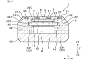
本実施形態のガスセンサ素子1は、図1、図2に示すごとく、電解質層2と第一絶縁体3と第二絶縁体4と測定ガス室5と基準ガス室6とを有する。電解質層2は、保持板22及び固体電解質体21を備える。保持板22は、保持板22の厚み方向(以後、Z方向という。)に貫通形成された配置穴220を備える。固体電解質体21は、配置穴220に配されている。固体電解質体21は、酸素イオン伝導性を有する。第一絶縁体3は、電解質層2の一方面に積層されている。第二絶縁体4は、電解質層2の他方面に積層されている。測定ガス室5は、電解質層2と第一絶縁体3とに囲まれている。図2に示すごとく、測定ガス室5は、被測定ガスGが導入される。基準ガス室6は、電解質層2と第二絶縁体4とに囲まれている。基準ガス室6は、基準ガスAが導入される。
(Embodiment 1)
An embodiment of the gas sensor element will be described with reference to FIGS. 1 to 5.
As shown in FIGS. 1 and 2, the gas sensor element 1 of the present embodiment has an
図1、図2に示すごとく、配置穴220と固体電解質体21との境界部23の少なくとも一部は、第一絶縁体3の第一挟持部33と、第二絶縁体4の第二挟持部45とによって挟持されている。第一挟持部33は、Z方向において境界部23と重なる位置に形成されている。また、第一挟持部33は、少なくとも、Z方向における測定ガス室5が配された全領域に形成されている。第二挟持部45は、Z方向において境界部23と重なる位置に形成されている。また、第二挟持部45は、少なくとも、厚み方向における基準ガス室6が配された全領域に形成されている。
以後、本実施形態につき、詳説する。
As shown in FIGS. 1 and 2, at least a part of the
Hereinafter, the present embodiment will be described in detail.
図5に示すごとく、ガスセンサ素子1を備えたガスセンサ10は、内燃機関としてのエンジンの図示しない排気管に配置される。ガスセンサ10は、排気管を通過する排ガスを被測定ガスGとするとともに、大気を基準ガスAとして、被測定ガスGの酸素濃度を求め、この酸素濃度に基づいてエンジンにおけるA/F(空燃比)を求めるA/Fセンサである。ガスセンサ10は、より具体的には、被測定ガスGの拡散律速に基づく限界電流特性を利用して、エンジンの空燃比を定量的に求めるA/Fセンサとすることができる。
As shown in FIG. 5, the
図1、図2、図4に示すごとく、ガスセンサ素子1は、第一絶縁体3、電解質層2、第二絶縁体4を、互いに厚み方向に積層し、焼結して形成されている。以後、第一絶縁体3、電解質層2、第二絶縁体4の積層方向をZ方向という。また、Z方向における、電解質層2に対する第一絶縁体3側をZ1側といい、その反対側、すなわち電解質層2に対する第二絶縁体4側をZ2側という。また、ガスセンサ素子1の長手方向をX方向という。X方向における、ガスセンサ素子1に被測定ガスGが導入される側を先端側とし、基準ガスAが導入される側を基端側とする。なお、適宜、先端側をX1側といい、基端側をX2側という。また、X方向とZ方向との双方に直交する方向をY方向という。Y方向は、ガスセンサ素子1の幅方向である。X方向とY方向とZ方向とは、互いに直交している。
As shown in FIGS. 1, 2, and 4, the gas sensor element 1 is formed by laminating a
前述のごとく、電解質層2は、保持板22と固体電解質体21とを備える。保持板22は、X方向に長尺でZ方向に厚みを有する板状を呈している。なお、図2〜図4においては、便宜上、ガスセンサ素子1のX方向の長さを、実際の長さよりも短く表している。
As described above, the
図2、図4に示すごとく、保持板22におけるX方向のX1側の領域に、配置穴220が形成されている。配置穴220は、X方向に長尺な長方形状を呈している。そして、配置穴220に、固体電解質体21が充填されている。
As shown in FIGS. 2 and 4, the
固体電解質体21は、ジルコニア系酸化物からなる。固体電解質体21は、ジルコニア(ZrO2)を主成分とし(すなわち、ジルコニアを50質量%以上含有し)、希土類金属元素又はアルカリ土類金属元素によってジルコニアの一部を置換させた安定化ジルコニア、部分安定化ジルコニア等の固体電解質からなる。固体電解質体21を構成するジルコニアの一部は、イットリア(Y2O3)、スカンジア(Sc2O3)又はカルシア(CaO)によって置換することができる。保持板22は、固体電解質体21よりも熱伝導性の高い材料からなる。
The
図1、図2に示すごとく、固体電解質体21のZ1側の面におけるX1側の領域には、測定ガス室5に導入される被測定ガスGに曝される測定電極11が配されている。また、固体電解質体21のZ2側の面におけるX1側の領域には、基準ガス室6に導入される基準ガスAに曝される基準電極12が配されている。測定電極11と基準電極12とは、固体電解質体21を介してZ方向に対向する対向領域13を有する。なお、以後、X方向におけるX1側と反対側をX2側という。
As shown in FIGS. 1 and 2, a
図4に示すごとく、測定電極11及び基準電極12のそれぞれは、対向領域13からX2側に電極リード部14が延設されている。一対の電極リード部14は、ガスセンサ素子1のX2側の端部付近まで延設されている。一対の電極リード部14は、第二絶縁体4に形成されたスルーホールを通って、第一絶縁体3のZ2側の面に形成された一対のセンサ端子15に接続されている。測定電極11及び基準電極12は、一対のセンサ端子15から、ガスセンサ素子1外部に電気接続される。
As shown in FIG. 4, each of the
測定電極11及び基準電極12は、酸素に対する触媒活性を示す貴金属としての白金、及び固体電解質体21と同じ材料、すなわちジルコニア系酸化物を含有している。測定電極11及び基準電極12が固体電解質体21と同じ材料を含有することにより、固体電解質体21に測定電極11及び基準電極12を構成するペースト状の電極材料を印刷(塗布)して焼結する際に、測定電極11及び基準電極12と固体電解質体21との結合強度を確保しやすい。
The
図1、図2、図4に示すごとく、電解質層2のZ1側の面に積層された第一絶縁体3は、チャンバ形成部32とヒータ埋設部31とをZ方向に積層してなる。チャンバ形成部32は、電解質層2のZ1側の面に配されている。図4に示すごとく、チャンバ形成部32は、X1側の端縁がX2側に凹んだ凹部320を備えた絶縁スペーサ321と、凹部320におけるX1側の開口端を閉塞するよう配された拡散抵抗部322とを有する。
As shown in FIGS. 1, 2, and 4, the
拡散抵抗部322は、被測定ガスGを所定の拡散速度で通過させるよう構成されている。拡散抵抗部322は、多孔質のアルミナ等の金属酸化物によって形成されている。被測定ガスGとしての排ガスは、拡散抵抗部322を通過して測定ガス室5に導入される。なお、拡散抵抗部322は、例えば測定ガス室5とガスセンサ素子1の外部空間とに連通する小さな貫通孔であるピンホールであってもよい。また、拡散抵抗部322の位置は、これに限られず、例えば測定ガス室5におけるY方向の一方側等、他の位置に形成することもできる。
The
図2に示すごとく、凹部320における絶縁スペーサ321と拡散抵抗部322とに囲まれた空間領域が、Z方向の両側から電解質層2とヒータ埋設部31とによって閉塞されて測定ガス室5を構成している。すなわち、チャンバ形成部32は、Z方向における測定ガス室5が形成された領域に配されており、測定ガス室5を区画している。
As shown in FIG. 2, the space region surrounded by the insulating
図3に示すごとく、Z方向から見たとき、測定ガス室5は、配置穴220と固体電解質体21との境界部23の内側に収まるよう形成されている。これに伴い、図1、図2に示すごとく、チャンバ形成部32は、境界部23の全体をZ1側から覆うよう形成されている。これにより、電解質層2における境界部23の気密性が低下することに起因して、境界部23を介して測定ガス室5と基準ガス室6とが連通することを防ぎやすい。なお、図3において、測定ガス室5の外形を二点鎖線で表しており、基準ガス室6の外形を破線で表している。
As shown in FIG. 3, when viewed from the Z direction, the
図1、図2に示すごとく、測定ガス室5のZ方向の長さは、電解質層2のZ方向の厚みよりも小さい。測定ガス室5は、測定電極11の対向領域13を少なくとも収容するよう形成されている。本実施形態において、Z方向から見たとき、測定ガス室5は、測定電極11の対向領域13よりも一回り大きく形成されている。
As shown in FIGS. 1 and 2, the length of the
図1、図2、図4に示すごとく、チャンバ形成部32のZ1側に、ヒータ埋設部31が積層されている。ヒータ埋設部31は、ガスセンサ素子1における最もZ1側の部位に形成されている。ヒータ埋設部31は、Z方向に積層された一対の埋設プレート311と、一対の埋設プレート311の間に埋設されたヒータ7とを有する。すなわち、ヒータ7は、第一絶縁体3に埋設されている。
As shown in FIGS. 1, 2, and 4, the heater embedded
図4に示すごとく、ヒータ7は、通電により発熱する発熱部71と、発熱部71に接続された一対のリード部72とを有する。図1、図2に示すごとく、発熱部71の少なくとも一部は、測定ガス室5とZ方向に重なる領域に配されている。発熱部71の少なくとも一部は、測定電極11の対向領域13及び基準電極12の対向領域13に対して、Z方向に重なるよう配されている。発熱部71は、一部が測定ガス室5とZ方向に重なる位置に配されており、他の一部がチャンバ形成部32の埋設プレート311とZ方向に重なる位置に配されている。発熱部71の一部は、測定ガス室5よりもX2側に形成されている。すなわち、発熱部71の一部は、埋設プレート311における測定ガス室5のX2側に隣接する部位に、Z方向に重なっている。
As shown in FIG. 4, the
図4に示すごとく、発熱部71は、Y方向の一方に向かうにつれて、X方向の両側に行ったり来たりする蛇行形状を有する。なお、発熱部71の形状はこれに限られず、例えばX方向の一方に向かうにつれて、Y方向の両側に行ったり来たりする蛇行形状とすることもできるし、その他の形状にすることも可能である。
As shown in FIG. 4, the
発熱部71の両端から、一対のリード部72が形成されている。リード部72は、ガスセンサ素子1のX2側の端部手前まで形成されている。一対のリード部72は、X1側の埋設プレート311のスルーホールを通って、埋設プレート311のX1側の面に形成された一対のヒータ端子16に接続されている。ヒータ7は、ヒータ端子16から、ガスセンサ素子1外部に電気接続される。
A pair of
発熱部71は、その形成方向に直交する断面の面積が、リード部72の形成方向に直交する断面の面積よりも小さい。そして、発熱部71は、単位長さ当たりの抵抗値が、リード部72の単位長さ当たりの抵抗値よりも大きい。一対のリード部72に電圧が印加されると、発熱部71がジュール熱によって発熱する。これによって生じた熱により、固体電解質体21が加熱され、活性化される。
The area of the cross section of the
図1、図2、図4に示すごとく、電解質層2のZ2側の面に積層された第二絶縁体4は、ダクト形成部42と支持部43とを有する。ダクト形成部42は、電解質層2のZ2側の面に配されている。ダクト形成部42は、Z方向における基準ガス室6が形成された領域に配されて基準ガス室6を区画している。Z方向において、ダクト形成部42は、測定ガス室5の長さよりも長い。ダクト形成部42は、略同形の三つの層をZ方向に積層した後に焼結してなる。
As shown in FIGS. 1, 2, and 4, the
図4に示すごとく、ダクト形成部42は、X2側に開口するU字状に形成されている。すなわち、ダクト形成部42は、X方向に延在するとともにY方向に互いに対向する一対の長辺部421と、一対の長辺部421のX1側端部をY方向に連結する短辺部422とを有する。図2に示すごとく、短辺部422のX2側の面は、Z2側に向かうほどX2側に向かう曲面状を呈している。Z方向において、ダクト形成部42は、測定ガス室5の長さよりも長い。
As shown in FIG. 4, the
図1、図2に示すごとく、電解質層2とダクト形成部42と支持部43とに囲まれてできるダクト形成部42の内側の空間領域が、基準ガス室6である。図2に示すごとく、基準ガス室6は、ガスセンサ素子1のX2側端部まで形成されているとともにX2側に開放されている。基準ガス室6には、ダクト形成部42のX2側の開放部から、基準ガスAとしての大気が導入される。
As shown in FIGS. 1 and 2, the space region inside the
図1に示すごとく、Y方向において、基準ガス室6の両端は、境界部23におけるY方向に互いに対向する一対の第一境界部231の内側に位置している。そして、ダクト形成部42は、一対の第一境界部231の全体をZ2側から覆うように形成されている。また、図2に示すごとく、X方向において、基準ガス室6のX1側端縁は、境界部23におけるX方向に対向する一対の第二境界部232の内側に位置している。そして、図3から分かるように、ダクト形成部(図1、図2、図4の符号42参照)は、一対の第二境界部232のうち、X1側の第二境界部232の全体をZ2側から覆うように形成されている。また、図3から分かるように、ダクト形成部(図1、図2、図4の符号42参照)は、境界部23における一対の第二境界部232のうち、X2側の第二境界部232の両端部をZ2側から覆うよう形成されている。Z方向から見たとき、第一境界部231の長さは、第二境界部232の長さよりも長い。
As shown in FIG. 1, in the Y direction, both ends of the reference gas chamber 6 are located inside a pair of
図1、図3に示すごとく、境界部23における、少なくとも一対の第一境界部231の全体は、第一絶縁体3と第二絶縁体4とによってZ方向の両側から挟持されている。また、図2、図3に示すごとく、境界部23における、少なくとも一対の第二境界部232のうちのX1側の第二境界部232の全体は、第一絶縁体3と第二絶縁体4とによって挟持されている。また、図3から分かるように、X2側の第二境界部232の両端部は、第一絶縁体(図1、図2、図4の符号3参照)と第二絶縁体(図1、図2、図4の符号4参照)4とによって挟持されている。すなわち、一対の第一境界部231の全体と、X1側の第二境界部232の全体と、X2側の第二境界部232の両端部とが、Z方向の両側から第一絶縁体3と第二絶縁体4とによって挟持されている。そして、第一絶縁体3のチャンバ形成部32及びヒータ埋設部31における境界部23とZ方向に重なる部位が第一挟持部33であり、第二絶縁体4のダクト形成部42及び支持部43における境界部23とZ方向に重なる部位が第二挟持部45である。第一絶縁体3及び第二絶縁体4のそれぞれは、境界部23を跨ぐように配されており、境界部23を挟持している。図2に示すごとく、X1側の第二境界部232のZ1側に位置する第一挟持部33の一部は、拡散抵抗部322によって構成されている。
As shown in FIGS. 1 and 3, at least a pair of
図1、図2に示すごとく、基準ガス室6のZ方向の長さは、測定ガス室5のZ方向の長さよりも大きい。本実施形態において、基準ガス室6のZ方向の長さは、測定ガス室5のZ方向の長さの3倍以上の長さを有するが、これに限られない。基準ガス室6のY方向の長さは、基準電極12のY方向の長さより若干長い。基準電極12は、Y方向における基準ガス室6の中央に位置している。
As shown in FIGS. 1 and 2, the length of the reference gas chamber 6 in the Z direction is larger than the length of the
基準ガス室6における短辺部422よりもX2側の領域の、X方向に直交する断面の面積は、測定ガス室5におけるX方向に直交する断面の面積よりも大きい。また、基準ガス室6全体は、測定ガス室5全体よりも体積が大きい。基準ガス室6の前述の断面積、Z方向の長さ、体積等が、測定ガス室5よりも大きいことにより、測定電極11における未燃ガスを反応させるための、基準ガスA中の酸素を、基準ガス室6から測定電極11へ十分に供給することができる。
The area of the cross section orthogonal to the X direction in the region X2 side of the
図1、図2、図4に示すごとく、ダクト形成部42のZ2側の面に、支持部43が積層されている。支持部43は、ガスセンサ素子1における最もZ2側の部位に形成されている。支持部43は、ダクト形成部42の内側空間、すなわち基準ガス室6をZ2側から閉塞している。
As shown in FIGS. 1, 2, and 4, the
本実施形態において、保持板22、チャンバ形成部32における絶縁スペーサ321、埋設プレート311、ダクト形成部42、及び支持部43は、互いに同じ材料からなる。具体的には、これらは、被測定ガスGの透過性を有さないアルミナ(Al2O3)からなる。
In the present embodiment, the holding
なお、図5に示すごとく、ガスセンサ素子1のX1側の部位は、測定電極(図1、図2、図4の符号11参照)に対する被毒物質、排気管内に生じる凝縮水等がガスセンサ素子1内部に進入しないようにするための保護層101が設けられている。保護層101は、アルミナなどの多孔質のセラミックス(金属酸化物)によって形成されている。保護層101の気孔率は、拡散抵抗部322の気孔率よりも大きく、保護層101を通過することができる被測定ガスGの流量は、拡散抵抗部322を通過することができる被測定ガスGの流量よりも多い。
As shown in FIG. 5, in the portion of the gas sensor element 1 on the X1 side, the gas sensor element 1 contains poisonous substances for the measurement electrodes (see
次に、図5を用いて、本実施形態のガスセンサ素子1を有するガスセンサ10につき説明する。
ガスセンサ10の軸方向は、X方向となるよう形成されている。換言すると、ガスセンサ素子1の長手方向は、ガスセンサ10の軸方向と平行である。ガスセンサ10は、ガスセンサ素子1、第一インシュレータ102、ハウジング103、第二インシュレータ104、複数の接点端子105を備える。第一インシュレータ102は、ガスセンサ素子1を保持する。ハウジング103は、第一インシュレータ102を保持する。第二インシュレータ104は、第一インシュレータ102に連結されている。複数の接点端子105は、第二インシュレータ104に保持されてガスセンサ素子1のセンサ端子15とヒータ端子16とに接触している。
Next, the
The axial direction of the
ガスセンサ10は、ハウジング103のX1の部分に装着された先端側カバー106、ハウジング103のX2側の部分に装着されて第二インシュレータ104、接点端子105等を覆う後端側カバー107、接点端子105に繋がるリード線100を後端側カバー107に保持するためのブッシュ108等を備える。
The
先端側カバー106は、内燃機関の排気管内に露出するよう配される。先端側カバー106の内側に、ガスセンサ素子1のX1側の部位が突出している。先端側カバー106には、被測定ガスGとしての排ガスを通過させるためのガス通過孔106aが形成されている。先端側カバー106は、二重構造のものとすることができ、一重構造のものとすることもできる。先端側カバー106のガス通過孔106aから先端側カバー106内に流入する被測定ガスGとしての排ガスは、ガスセンサ素子1の保護層101及び拡散抵抗部322を通過して測定電極11へと導かれる。
The
後端側カバー107は、内燃機関の排気管の外部に配置される。後端側カバー107には、後端側カバー107内へ基準ガスAとしての大気を導入するための大気導入孔109が形成されている。大気導入孔109には、液体を通過させない一方、気体を通過させるフィルタ109aが配置されている。大気導入孔109から後端側カバー107内に導入される基準ガスAは、後端側カバー107内の隙間及び基準ガス室6を通って基準電極12へと導かれる。
The rear
接点端子105は、ヒータ端子16、センサ端子15のそれぞれに接続されるよう、第二インシュレータ104に複数配置されている。また、リード線100は、接点端子105に接続されている。
A plurality of
リード線100は、ガスセンサ10におけるガス検出の制御を行うセンサ制御装置に電気接続される。センサ制御装置は、エンジンにおける燃焼運転を制御するエンジン制御装置と連携してガスセンサ10における電気制御を行うものである。センサ制御装置には、測定電極11と基準電極12との間に流れる電流を測定する測定回路、測定電極11と基準電極12との間に電圧を印加する印加回路、ヒータ7に通電を行うための通電回路等が形成されている。なお、センサ制御装置は、エンジン制御装置内に構築してもよい。
The
次に、本実施形態の作用効果につき説明する。
本実施形態のガスセンサ10において、保持板22の配置穴220と固体電解質体21との境界部23の少なくとも一部は、第一絶縁体3の第一挟持部33と第二絶縁体4の第二挟持部45とによって挟持されている。そして、第一挟持部33は、少なくとも、Z方向における測定ガス室5が配された全領域に形成されている。また、第二挟持部45は、少なくとも、Z方向における基準ガス室6が配された全領域に形成されている。すなわち、境界部23の少なくとも一部は、比較的剛性の高い構造体で構成される第一挟持部33及び第二挟持部45により挟持されている。それゆえ、境界部23の少なくとも一部を挟持する第一挟持部33及び第二挟持部45の剛性を確保しやすく、固体電解質体21を配置穴220に安定して保持しやすい。
Next, the action and effect of this embodiment will be described.
In the
また、電解質層2は、固体電解質体21と保持板22とを有する。そして、保持板22は、固体電解質体21よりも熱伝導性の高い材料からなる。それゆえ、電解質層2全体として熱伝導を向上させやすい。それゆえ、ヒータ7によって効率的に固体電解質体21を加熱しやすく、固体電解質体21の早期活性化を図りやすい。
Further, the
また、本実施形態においては、チャンバ形成部32及びヒータ埋設部31とダクト形成部42及び支持部43とによって境界部23を保持できるため、境界部23を保持するためだけのシートを、境界部23両面に配置する必要がなく、製造工数の増加の防止、生産性の向上を図ることができる。
Further, in the present embodiment, since the
また、境界部23における少なくとも一対の第一境界部231の全体は、第一挟持部33と第二挟持部45とによって挟持されている。さらに、境界部23における一対の第一境界部231におけるX1側の第二境界部232の全体は、第一挟持部33と第二挟持部45とによって挟持されている。それゆえ、第一挟持部33と第二挟持部45とによって、境界部23を安定して挟持することができ、配置穴220から固体電解質体21が抜け落ちることを一層防止しやすい。
Further, at least the entire pair of the
また、ガスセンサ素子1は、第一絶縁体3に埋設されたヒータ7を有する。それゆえ、ヒータ7から固体電解質体21までの間に、比較的低温の基準ガスAが導入される基準ガス室6が配されない。それゆえ、ヒータ7から固体電解質体21までの熱伝導性を向上させやすく、固体電解質体21を早期に活性化させることができる。
Further, the gas sensor element 1 has a
以上のごとく、本実施形態によれば、固体電解質体が配置穴から抜け落ち難いガスセンサ素子を提供することができる。 As described above, according to the present embodiment, it is possible to provide a gas sensor element in which the solid electrolyte body does not easily fall out of the arrangement hole.
(実施形態2)
本実施形態は、図6〜図8に示すごとく、実施形態1に対して、電解質層2の形状を変更した実施形態である。
(Embodiment 2)
As shown in FIGS. 6 to 8, the present embodiment is an embodiment in which the shape of the
図7、図8に示すごとく、保持板22は、X2側に開放されたU字状に形成されている。そして、U字状の保持板22の内側の領域が、固体電解質体21を配置する配置穴220となっている。配置穴220は、保持板22におけるX2側端縁まで形成されており、X2側に開放されている。
As shown in FIGS. 7 and 8, the holding
図6〜図8に示すごとく、配置穴220に固体電解質体21が充填されている。X方向において、固体電解質体21のX2側端部は、保持板22のX2側端部の位置まで形成されている。固体電解質体21のX2側端部は、保持板22に接触しておらず、保持板22からX2側に露出している。境界部23は、固体電解質体21のX2側の端縁以外の部位と、配置穴220との間に形成されている。
As shown in FIGS. 6 to 8, the
そして、図6、図7に示すごとく、本実施形態においては、境界部23の全体が第一挟持部33と第二挟持部45とによって挟持されている。すなわち、境界部23の全体は、Z1側から第一挟持部33を構成するチャンバ形成部32によって覆われており、Z2側から第二挟持部45を構成するダクト形成部42によって覆われている。
Then, as shown in FIGS. 6 and 7, in the present embodiment, the
その他は、実施形態1と同様である。
なお、実施形態2以降において用いた符号のうち、既出の実施形態において用いた符号と同一のものは、特に示さない限り、既出の実施形態におけるものと同様の構成要素等を表す。
Others are the same as in the first embodiment.
In addition, among the codes used in the second and subsequent embodiments, the same codes as those used in the above-described embodiments represent the same components and the like as those in the above-mentioned embodiments, unless otherwise specified.
本実施形態においては、境界部23の全体が、第一挟持部33と第二挟持部45とによって挟持されている。それゆえ、一層安定して境界部23を挟持することができる。
その他、実施形態1と同様の作用効果を有する。
In the present embodiment, the
In addition, it has the same effect as that of the first embodiment.
本発明は、前記各実施形態に限定されるものではなく、その要旨を逸脱しない範囲において種々の実施形態に適用することが可能である。 The present invention is not limited to each of the above-described embodiments, and can be applied to various embodiments without departing from the gist thereof.
例えば、前記各実施形態において、ガスセンサは、エンジンにおける燃料と空気との混合比である空燃比が、理論空燃比に対して燃料過剰なリッチ状態にあるか空気過剰なリーン状態にあるかを検出する濃淡電池式のものとすることもできる。また、ガスセンサは、排ガス中のNOx濃度を検出するNOxセンサ等、A/Fセンサ以外のガスセンサとして構成することもできる。ガスセンサをNOxセンサとして用いる場合は、固体電解質体のX1側の測定ガス室側の面には、測定ガス室内の酸素濃度を所定の濃度以下に調整するためのポンプ電極と、NOx濃度を測定するための測定電極とが設けられる。この場合、ガスセンサ素子においては、測定電極と基準電極との間に流れる被測定ガスのNOx濃度に応じた電流値に基づいて、被測定ガスのNOx濃度が求められる。 For example, in each of the above embodiments, the gas sensor detects whether the air-fuel ratio, which is the mixing ratio of fuel and air in the engine, is in a fuel-rich state or an air-excessive lean state with respect to the stoichiometric air-fuel ratio. It can also be a light and light battery type. Further, the gas sensor can also be configured as a gas sensor other than the A / F sensor, such as a NOx sensor that detects the NOx concentration in the exhaust gas. When a gas sensor is used as a NOx sensor, a pump electrode for adjusting the oxygen concentration in the measurement gas chamber to a predetermined concentration or less and a NOx concentration are measured on the surface of the solid electrolyte on the X1 side of the measurement gas chamber. A measurement electrode is provided for this purpose. In this case, in the gas sensor element, the NOx concentration of the measurement gas is obtained based on the current value corresponding to the NOx concentration of the measurement gas flowing between the measurement electrode and the reference electrode.
1 ガスセンサ素子
2 電解質層
21 固体電解質体
22 保持板
220 配置穴
23 境界部
3 第一絶縁体
33 第一挟持部
4 第二絶縁体
45 第二挟持部
1
Claims (4)
前記電解質層の一方面に積層された第一絶縁体(3)と、
前記電解質層の他方面に積層された第二絶縁体(4)と、
前記電解質層と前記第一絶縁体とに囲まれるとともに被測定ガス(G)が導入される測定ガス室(5)と、
前記電解質層と前記第二絶縁体とに囲まれるとともに基準ガス(A)が導入される基準ガス室(6)と、
前記第一絶縁体に埋設されたヒータ(7)と、を有するガスセンサ素子(1)であって、
前記配置穴と前記固体電解質体との境界部(23)の少なくとも一部は、前記第一絶縁体の第一挟持部(33)と、前記第二絶縁体の第二挟持部(45)とによって挟持されており、
前記第一挟持部は、前記厚み方向において前記境界部と重なる位置に形成されているとともに、少なくとも、前記厚み方向における前記測定ガス室が配された全領域に形成されており、
前記第二挟持部は、前記厚み方向において前記境界部と重なる位置に形成されているとともに、少なくとも、前記厚み方向における前記基準ガス室が配された全領域に形成されており、
前記境界部は、前記ガスセンサ素子の幅方向(Y)に対向する一対の第一境界部(231)を有し、少なくとも一対の前記第一境界部の全体は、前記第一挟持部と前記第二挟持部とによって挟持されている、ガスセンサ素子。 An electrolyte layer (2) including a holding plate (22) having an arrangement hole (220) formed through the thickness direction (Z), and a solid electrolyte body (21) arranged in the arrangement hole and having oxygen ion conductivity. )When,
The first insulator (3) laminated on one surface of the electrolyte layer and
The second insulator (4) laminated on the other surface of the electrolyte layer and
A measurement gas chamber (5) surrounded by the electrolyte layer and the first insulator and into which the gas to be measured (G) is introduced.
A reference gas chamber (6) surrounded by the electrolyte layer and the second insulator and into which the reference gas (A) is introduced.
A heater (7) embedded in the first insulator, a gas sensor element to have a (1),
At least a part of the boundary portion (23) between the arrangement hole and the solid electrolyte body includes a first sandwiching portion (33) of the first insulator and a second sandwiching portion (45) of the second insulator. Is sandwiched by
The first sandwiching portion is formed at a position overlapping the boundary portion in the thickness direction, and is formed at least in the entire region where the measurement gas chamber is arranged in the thickness direction.
The second sandwiching portion is formed at a position overlapping the boundary portion in the thickness direction, and is formed at least in the entire region where the reference gas chamber is arranged in the thickness direction.
The boundary portion has a pair of first boundary portions (231) facing each other in the width direction (Y) of the gas sensor element, and at least the entire pair of the first boundary portions is the first holding portion and the first holding portion. A gas sensor element that is sandwiched between the two sandwiches .
前記電解質層の一方面に積層された第一絶縁体(3)と、
前記電解質層の他方面に積層された第二絶縁体(4)と、
前記電解質層と前記第一絶縁体とに囲まれるとともに被測定ガス(G)が導入される測定ガス室(5)と、
前記電解質層と前記第二絶縁体とに囲まれるとともに基準ガス(A)が導入される基準ガス室(6)と、を有するガスセンサ素子(1)であって、
前記固体電解質体及び前記基準ガス室は、前記ガスセンサ素子の長手方向(X)の基端位置まで形成されており、
前記配置穴と前記固体電解質体との境界部(23)の少なくとも一部は、前記第一絶縁体の第一挟持部(33)と、前記第二絶縁体の第二挟持部(45)とによって挟持されており、
前記第一挟持部は、前記厚み方向において前記境界部と重なる位置に形成されているとともに、少なくとも、前記厚み方向における前記測定ガス室が配された全領域に形成されており、
前記第二挟持部は、前記厚み方向において前記境界部と重なる位置に形成されているとともに、少なくとも、前記厚み方向における前記基準ガス室が配された全領域に形成されており、
前記境界部は、前記ガスセンサ素子の幅方向(Y)に対向する一対の第一境界部(231)を有し、少なくとも一対の前記第一境界部の全体は、前記ガスセンサ素子の長手方向の基端位置まで前記第一挟持部と前記第二挟持部とによって挟持されている、ガスセンサ素子。 An electrolyte layer (2) including a holding plate (22) having an arrangement hole (220) formed through the thickness direction (Z), and a solid electrolyte body (21) arranged in the arrangement hole and having oxygen ion conductivity. )When,
The first insulator (3) laminated on one surface of the electrolyte layer and
The second insulator (4) laminated on the other surface of the electrolyte layer and
A measurement gas chamber (5) surrounded by the electrolyte layer and the first insulator and into which the gas to be measured (G) is introduced.
The electrolyte layer and the reference gas chamber reference gas (A) is introduced together surrounded by the second insulating body (6), a gas sensor element to have a (1),
The solid electrolyte body and the reference gas chamber are formed up to the base end position in the longitudinal direction (X) of the gas sensor element.
At least a part of the boundary portion (23) between the arrangement hole and the solid electrolyte body includes a first sandwiching portion (33) of the first insulator and a second sandwiching portion (45) of the second insulator. Is sandwiched by
The first sandwiching portion is formed at a position overlapping the boundary portion in the thickness direction, and is formed at least in the entire region where the measurement gas chamber is arranged in the thickness direction.
The second sandwiching portion is formed at a position overlapping the boundary portion in the thickness direction, and is formed at least in the entire region where the reference gas chamber is arranged in the thickness direction.
The boundary portion has a pair of first boundary portions (231) facing the width direction (Y) of the gas sensor element, and at least the entire pair of the first boundary portions is a base in the longitudinal direction of the gas sensor element. A gas sensor element that is sandwiched between the first sandwiching portion and the second sandwiching portion up to the end position .
Priority Applications (3)
| Application Number | Priority Date | Filing Date | Title |
|---|---|---|---|
| JP2018156179A JP6917349B2 (en) | 2018-08-23 | 2018-08-23 | Gas sensor element |
| PCT/JP2019/031225 WO2020039942A1 (en) | 2018-08-23 | 2019-08-07 | Gas sensor element |
| US17/181,212 US20210181140A1 (en) | 2018-08-23 | 2021-02-22 | Gas sensor element |
Applications Claiming Priority (1)
| Application Number | Priority Date | Filing Date | Title |
|---|---|---|---|
| JP2018156179A JP6917349B2 (en) | 2018-08-23 | 2018-08-23 | Gas sensor element |
Publications (3)
| Publication Number | Publication Date |
|---|---|
| JP2020030123A JP2020030123A (en) | 2020-02-27 |
| JP2020030123A5 JP2020030123A5 (en) | 2020-07-16 |
| JP6917349B2 true JP6917349B2 (en) | 2021-08-11 |
Family
ID=69593097
Family Applications (1)
| Application Number | Title | Priority Date | Filing Date |
|---|---|---|---|
| JP2018156179A Active JP6917349B2 (en) | 2018-08-23 | 2018-08-23 | Gas sensor element |
Country Status (3)
| Country | Link |
|---|---|
| US (1) | US20210181140A1 (en) |
| JP (1) | JP6917349B2 (en) |
| WO (1) | WO2020039942A1 (en) |
Family Cites Families (9)
| Publication number | Priority date | Publication date | Assignee | Title |
|---|---|---|---|---|
| JP2800196B2 (en) * | 1988-09-29 | 1998-09-21 | トヨタ自動車株式会社 | Manufacturing method of stacked oxygen concentration sensor |
| JP3874690B2 (en) * | 2002-03-29 | 2007-01-31 | 日本特殊陶業株式会社 | Multilayer gas sensor element, method for manufacturing the same, and gas sensor |
| JP5104744B2 (en) * | 2008-12-18 | 2012-12-19 | 株式会社デンソー | Gas sensor element and manufacturing method thereof |
| JP5500148B2 (en) * | 2011-09-27 | 2014-05-21 | 株式会社デンソー | Gas sensor element, method of manufacturing the same, and gas sensor |
| JP6294800B2 (en) * | 2014-09-25 | 2018-03-14 | 日本特殊陶業株式会社 | GAS SENSOR ELEMENT, GAS SENSOR AND GAS SENSOR ELEMENT MANUFACTURING METHOD |
| JP6762145B2 (en) * | 2016-06-14 | 2020-09-30 | 日本特殊陶業株式会社 | Gas sensor element and gas sensor |
| JP2017226507A (en) * | 2016-06-21 | 2017-12-28 | 株式会社日立ビルシステム | Elevator |
| JP6830038B2 (en) * | 2017-06-13 | 2021-02-17 | 日本特殊陶業株式会社 | Sensor element and gas sensor equipped with it |
| JP2019095359A (en) * | 2017-11-27 | 2019-06-20 | 日本特殊陶業株式会社 | Sensor element, and gas sensor with the same |
-
2018
- 2018-08-23 JP JP2018156179A patent/JP6917349B2/en active Active
-
2019
- 2019-08-07 WO PCT/JP2019/031225 patent/WO2020039942A1/en active Application Filing
-
2021
- 2021-02-22 US US17/181,212 patent/US20210181140A1/en active Pending
Also Published As
| Publication number | Publication date |
|---|---|
| JP2020030123A (en) | 2020-02-27 |
| WO2020039942A1 (en) | 2020-02-27 |
| US20210181140A1 (en) | 2021-06-17 |
Similar Documents
| Publication | Publication Date | Title |
|---|---|---|
| EP0310206B1 (en) | Electrochemical device | |
| JP4828753B2 (en) | Sensor member for defining oxygen concentration in gas mixture and method for manufacturing the sensor member | |
| US4728411A (en) | Electrochemical device | |
| EP0142992A1 (en) | Electrochemical device incorporating a sensing element | |
| JPS58153155A (en) | Oxygen sensor | |
| JP7089988B2 (en) | Gas sensor element | |
| JP4532046B2 (en) | Electrochemical gas sensor and gas component identification method | |
| JP2020071128A (en) | Gas sensor element | |
| JP6814086B2 (en) | Gas sensor element and gas sensor | |
| JPH0222692Y2 (en) | ||
| EP0220067A1 (en) | Sensor incorporating a heater | |
| JP6917349B2 (en) | Gas sensor element | |
| JP7125372B2 (en) | gas sensor | |
| JP2002139468A (en) | Gas sensor | |
| JP3587282B2 (en) | Nitrogen oxide concentration detector | |
| JP7138055B2 (en) | gas sensor | |
| US20220011257A1 (en) | Gas sensor | |
| JP6517613B2 (en) | Gas sensor | |
| JPH0417382B2 (en) | ||
| US20190391109A1 (en) | Gas sensor | |
| JP6438851B2 (en) | Gas sensor element and gas sensor | |
| JP4705005B2 (en) | Gas sensor element and gas sensor | |
| JP2003021613A (en) | Gas sensor element | |
| JP7068132B2 (en) | Gas sensor | |
| JP3509329B2 (en) | Oxygen concentration detection element |
Legal Events
| Date | Code | Title | Description |
|---|---|---|---|
| A521 | Written amendment |
Free format text: JAPANESE INTERMEDIATE CODE: A523 Effective date: 20200603 |
|
| A621 | Written request for application examination |
Free format text: JAPANESE INTERMEDIATE CODE: A621 Effective date: 20201109 |
|
| A131 | Notification of reasons for refusal |
Free format text: JAPANESE INTERMEDIATE CODE: A131 Effective date: 20210330 |
|
| A521 | Written amendment |
Free format text: JAPANESE INTERMEDIATE CODE: A523 Effective date: 20210521 |
|
| TRDD | Decision of grant or rejection written | ||
| A01 | Written decision to grant a patent or to grant a registration (utility model) |
Free format text: JAPANESE INTERMEDIATE CODE: A01 Effective date: 20210622 |
|
| A61 | First payment of annual fees (during grant procedure) |
Free format text: JAPANESE INTERMEDIATE CODE: A61 Effective date: 20210719 |
|
| R150 | Certificate of patent or registration of utility model |
Ref document number: 6917349 Country of ref document: JP Free format text: JAPANESE INTERMEDIATE CODE: R150 |